pwmpal (#28020) sheets/parallax pdfs...automatic. before installing the pwmpal, you should perform...
TRANSCRIPT

© Parallax, Inc. • PWMPAL (#28020) • 02/2005 Page 1
599 Menlo Drive, Suite 100Rocklin, California 95765, USAOffice: (916) 624-8333Fax: (916) 624-8003
General: [email protected]: [email protected] Site: www.parallax.comEducational: www.stampsinclass.com
PWMPAL (#28020)PWM Generation, Control, and Background Counting
Introduction
The PWMPAL is an intelligent peripheral that adds up to four PWM output channels and up to four control/counter input channels to the 24-pin versions of the BASIC Stamp® microcontroller. PWM channels can be configured to operate under software control, or under hardware control through the corresponding counter input channel. In addition to PWM waveform generation, the PWMPAL has four 16-bit counters that operate at all times, even when the counter pin is used for hardware PWM control. Communication with the PWMPAL is handled through a bi-directional serial connection on pin P0 of the microntroller module. The Parallax AppMod communications protocol is used, allowing baud rates of9600, 19,200 and 38,400 baud.
Examples of PWMPAL Uses:
• Servo or DC motor control for robotics and animatronics• AC waveform (square wave) generation for bi-color LEDs and sensors• Background counting for process control, robotic motion monitoring, etc.
Packing List
Verify that your PWMPAL kit is complete in accordance with the list below:
• PWMPAL "Smart Socket" module• Documentation
Note: PWMPAL demonstration software files may be downloaded from www.parallax.com.
Features
• Up to four simultaneous PWM outputs• Independent control of each PWM output high-time, low-time, and phase• Generate frequencies from 0.3 Hz to 20 kHz; duty cycle independent *• Outputs may operate under software or hardware control• Up to four 16-bit counters• Auto-baud detection (9600, 19.2K, 38.4K) for Host-to-PWMPAL communications• Requires no PCB "real estate" – mounts underneath microcontroller module
* Duty cycle independence is not available for the entire range of output frequencies
© Parallax, Inc. • PWMPAL (#28020) • 02/2005 Page 2
Connections
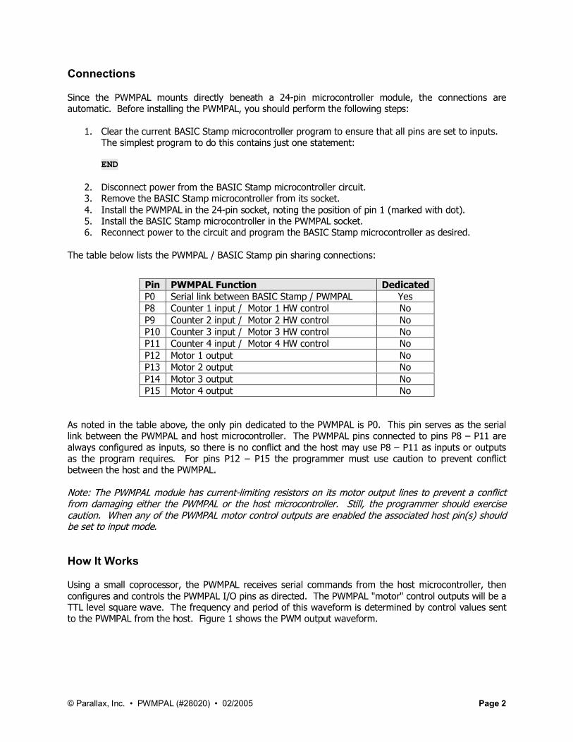
Since the PWMPAL mounts directly beneath a 24-pin microcontroller module, the connections are automatic. Before installing the PWMPAL, you should perform the following steps:
1. Clear the current BASIC Stamp microcontroller program to ensure that all pins are set to inputs. The simplest program to do this contains just one statement:
END
2. Disconnect power from the BASIC Stamp microcontroller circuit.3. Remove the BASIC Stamp microcontroller from its socket.4. Install the PWMPAL in the 24-pin socket, noting the position of pin 1 (marked with dot).5. Install the BASIC Stamp microcontroller in the PWMPAL socket.6. Reconnect power to the circuit and program the BASIC Stamp microcontroller as desired.
The table below lists the PWMPAL / BASIC Stamp pin sharing connections:
As noted in the table above, the only pin dedicated to the PWMPAL is P0. This pin serves as the serial link between the PWMPAL and host microcontroller. The PWMPAL pins connected to pins P8 – P11 are always configured as inputs, so there is no conflict and the host may use P8 – P11 as inputs or outputs as the program requires. For pins P12 – P15 the programmer must use caution to prevent conflict between the host and the PWMPAL.
Note: The PWMPAL module has current-limiting resistors on its motor output lines to prevent a conflict from damaging either the PWMPAL or the host microcontroller. Still, the programmer should exercise caution. When any of the PWMPAL motor control outputs are enabled the associated host pin(s) should be set to input mode.
How It Works
Using a small coprocessor, the PWMPAL receives serial commands from the host microcontroller, then configures and controls the PWMPAL I/O pins as directed. The PWMPAL "motor" control outputs will be a TTL level square wave. The frequency and period of this waveform is determined by control values sent to the PWMPAL from the host. Figure 1 shows the PWM output waveform.
Pin PWMPAL Function DedicatedP0 Serial link between BASIC Stamp / PWMPAL YesP8 Counter 1 input / Motor 1 HW control NoP9 Counter 2 input / Motor 2 HW control NoP10 Counter 3 input / Motor 3 HW control NoP11 Counter 4 input / Motor 4 HW control NoP12 Motor 1 output NoP13 Motor 2 output NoP14 Motor 3 output NoP15 Motor 4 output No

© Parallax, Inc. • PWMPAL (#28020) • 02/2005 Page 3
Figure 1 – PWM Output
The PWMPAL gives the program control of the on- and off-time values, hence giving control of the output frequency and duty cycle. In the PWMPAL, the on and off times are specified with 16-bit values in units of 25 microseconds (0.000025 seconds). Using the formula:
Frequency = 1 / Period
the minimum and maximum output frequencies of the PWMPAL can be calculated. Given the minimum and maximum values for on- and off-time:
Frequency (max) = 1 / ((1 x 0.000025) + (1 x 0.000025)) 1 / 0.00005 = 20,000 HzFrequency (min) = 1 / ((65535 x 0.000025) + (65535 x 0.000025)) 1 / 3.27675 = 0.30518 Hz
Duty Cycle describes the relationship between the on-time and the total period in terms of percent. With full control of the on- and off-time values, the programmer can set the frequency and duty cycle as required. If, for example, the desired PWM output was 1000 Hz with duty cycle of 40%, the following steps would be used to calculate the on-time and off-time values:
1. Determine the waveform period (1 / Frequency):
1 / 1000 = 0.001
2. Determine the PWMPAL units in the period:
0.001 / 0.000025 = 40
3. For the on-time, multiply the total period units by the desired duty cycle:
40 x 0.4 = 16
4. For the off-time, subtract the on-time units from the total period units:
40 – 16 = 24
See the following sections for specifics on sending PWM on- and off-time values to the PWMPAL.

© Parallax, Inc. • PWMPAL (#28020) • 02/2005 Page 4
PWMPAL Commands
All PWMPAL commands (except ID, see below) follow the Parallax AppMod serial protocol and will begin with the string:
"!PWM"
The "!" is used for synchronization and baud rate detection; the "PWM" identifies the device type. What follows will generally be a command letter and unit identifier.
"ID" Request PWMPAL ID String
Use: SEROUT 0, baud, ["!ID]SERIN 0, baud, [STR version\3]
baud variable or constant value for 9600, 19.2K, or 38.4K baud (host-dependent value )version 3-byte array to hold version string
The "!ID" command requests the PWMPAL ID string (three ASCII characters). Note that this command does not follow the standard AppMod protocol by specifying the device type in the command string, so it should NOT be used on the same serial connection as other AppMod devices.
"Mn" Set PWM Motor Timing Control Values
Use: SEROUT 0, baud, ["!PWMMx", tOn.BYTE0, tOn.BYTE1, tOff.BYTE0, tOff.BYTE1]
baud variable or constant value for 9600, 19.2K, or 38.4K baudn "1" to "4" – specifying the PWMPAL output channel (P12 – P15)tOn variable or constant for on-time; in 25 microsecond unitstOff variable or constant for off-time; in 25 microsecond units
The "Mn" command sets the on- and off-time values for a specified PWM channel. Note that the 16-bit on- and off-time values must be transmitted as bytes, low-byte first.
Example (Baudmode value for BS2 microcontroller ):
SEROUT 0, 6, ["!PWMM1", 2, 0, 6, 0]
The example above configures PWM channel 1 (P12) to have an output frequency of 5000 Hz with a duty cycle of 25%.
It is important to note that setting the on- and off-time values does not enable the PWM output channelif it was previously disabled. This is handled separately through the Set Status command (see below). Finally, there is a special-case use of the "Mn" command: "M0". For example:
SEROUT 0, 6, ["!PWMM0"]
The purpose of this command is to disable all PWM output channels; returning all to a Hi-Z state.
© Parallax, Inc. • PWMPAL (#28020) • 02/2005 Page 5
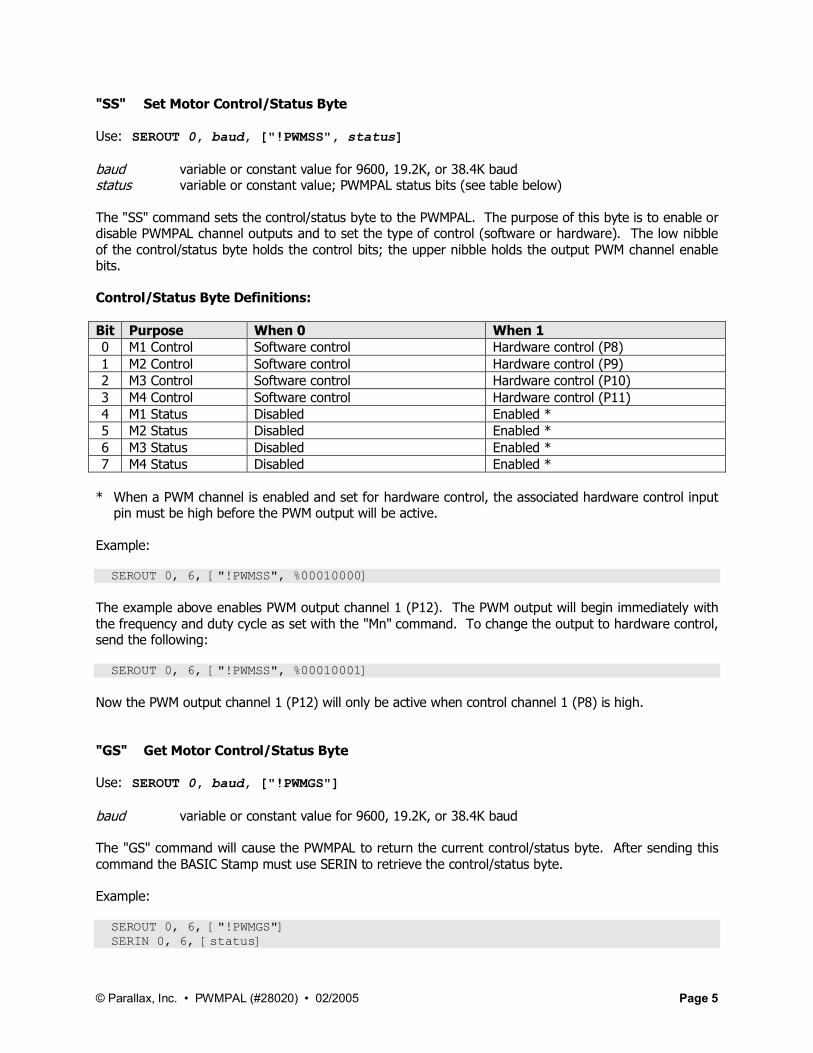
"SS" Set Motor Control/Status Byte
Use: SEROUT 0, baud, ["!PWMSS", status]
baud variable or constant value for 9600, 19.2K, or 38.4K baudstatus variable or constant value; PWMPAL status bits (see table below)
The "SS" command sets the control/status byte to the PWMPAL. The purpose of this byte is to enable or disable PWMPAL channel outputs and to set the type of control (software or hardware). The low nibble of the control/status byte holds the control bits; the upper nibble holds the output PWM channel enable bits.
Control/Status Byte Definitions:
Bit Purpose When 0 When 10 M1 Control Software control Hardware control (P8)1 M2 Control Software control Hardware control (P9)2 M3 Control Software control Hardware control (P10)3 M4 Control Software control Hardware control (P11)4 M1 Status Disabled Enabled *5 M2 Status Disabled Enabled *6 M3 Status Disabled Enabled *7 M4 Status Disabled Enabled *
* When a PWM channel is enabled and set for hardware control, the associated hardware control input pin must be high before the PWM output will be active.
Example:
SEROUT 0, 6, ["!PWMSS", %00010000]
The example above enables PWM output channel 1 (P12). The PWM output will begin immediately with the frequency and duty cycle as set with the "Mn" command. To change the output to hardware control, send the following:
SEROUT 0, 6, ["!PWMSS", %00010001]
Now the PWM output channel 1 (P12) will only be active when control channel 1 (P8) is high.
"GS" Get Motor Control/Status Byte
Use: SEROUT 0, baud, ["!PWMGS"]
baud variable or constant value for 9600, 19.2K, or 38.4K baud
The "GS" command will cause the PWMPAL to return the current control/status byte. After sending this command the BASIC Stamp must use SERIN to retrieve the control/status byte.
Example:
SEROUT 0, 6, ["!PWMGS"] SERIN 0, 6, [status]
© Parallax, Inc. • PWMPAL (#28020) • 02/2005 Page 6
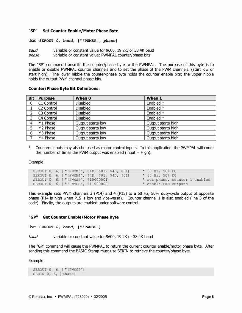
"SP" Set Counter Enable/Motor Phase Byte
Use: SEROUT 0, baud, ["!PWMSP", phase]
baud variable or constant value for 9600, 19.2K, or 38.4K baudphase variable or constant value; PWMPAL counter/phase bits
The "SP" command transmits the counter/phase byte to the PWMPAL. The purpose of this byte is to enable or disable PWMPAL counter channels and to set the phase of the PWM channels. (start low or start high). The lower nibble the counter/phase byte holds the counter enable bits; the upper nibble holds the output PWM channel phase bits.
Counter/Phase Byte Bit Definitions:
Bit Purpose When 0 When 10 C1 Control Disabled Enabled *1 C2 Control Disabled Enabled *2 C3 Control Disabled Enabled *3 C4 Control Disabled Enabled *4 M1 Phase Output starts low Output starts high5 M2 Phase Output starts low Output starts high6 M3 Phase Output starts low Output starts high7 M4 Phase Output starts low Output starts high
* Counters inputs may also be used as motor control inputs. In this application, the PWMPAL will count the number of times the PWM output was enabled (input = High).
Example:
SEROUT 0, 6, ["!PWMM3", $4D, $01, $4D, $01] ' 60 Hz, 50% DC SEROUT 0, 6, ["!PWMM4", $4D, $01, $4D, $01] ' 60 Hz, 50% DC SEROUT 0, 6, ["!PWMSP", %10000001] ' set phase, counter 1 enabled SEROUT 0, 6, ["!PWMSS", %11000000] ' enable PWM outputs
This example sets PWM channels 3 (P14) and 4 (P15) to a 60 Hz, 50% duty-cycle output of opposite phase (P14 is high when P15 is low and vice-versa). Counter channel 1 is also enabled (line 3 of the code). Finally, the outputs are enabled under software control.
"GP" Get Counter Enable/Motor Phase Byte
Use: SEROUT 0, baud, ["!PWMGP"]
baud variable or constant value for 9600, 19.2K or 38.4K baud
The "GP" command will cause the PWMPAL to return the current counter enable/motor phase byte. After sending this command the BASIC Stamp must use SERIN to retrieve the counter/phase byte.
Example:
SEROUT 0, 6, ["!PWMGP"] SERIN 0, 6, [phase]

© Parallax, Inc. • PWMPAL (#28020) • 02/2005 Page 7
"Cn" Get Counter Value
Use: SEROUT 0, baud, ["!PWMCn"]
baud variable or constant value for 9600, 19.2K, or 38.4K baudn "1" to "4" – specifying the PWMPAL counter channel (P8 – P11)
The "Cn" command will cause the PWMPAL to return the current value of the specified counter channel. After sending this command the BASIC Stamp must use SERIN to retrieve the counter data.
Example:
SEROUT 0, 6, ["!PWMC1"] ' get counter 1 SERIN 0, 6, [cntr1.LOWBYTE, cntr1.HIGHBYTE] ' receive value
By using "C0" the value of all counters will be returned. The SERIN function must be setup to receive eight bytes when "C0" is used.
"Xn" Clear Counter Value
Use: SEROUT 0, baud, ["!PWMXn"]
baud variable or constant value for 9600, 19.2K, or 38.4K baudn "1" to "4" – specifying the PWMPAL counter channel (P8 – P11)
The "Xn" command will cause the PWMPAL to clear (reset to zero) the specified counter channel value.
Example:
SEROUT 0, 6, ["!PWMX1"] ' clear counter 1
By using "X0" the value of all counters will be reset to zero.
Programming the PWMPAL
The examples that follow will demonstrate how easy the PWMPAL is to program. The programmer must keep in mind, however, that using BASIC Stamp microcontroller pins P12 – P15 as outputs should be done with extreme caution as there could be a conflict with the PWMPAL that leads to unpredictable results. Design your code carefully so that PWMPAL outputs do not conflict with host outputs on these pins.

© Parallax, Inc. • PWMPAL (#28020) • 02/2005 Page 8
Example 1 – PWMPAL Programming Template
For advanced programs a template is often useful to keep organized and prevent errors. This template file contains useful constant and variable values for programs that utilize the PWMPAL. Conditional compilation defintions allow this program to work properly with all BS2-family modules.
' ========================================================================='' File....... PWMPAL_Template.BS2' Purpose.... Template for PWMPAL Programs' Author..... Parallax' E-mail..... [email protected]' Started....' Updated.... 09 FEB 2005'' {$STAMP BS2}' {$PBASIC 2.5}'' =========================================================================
' -----[ Program Description ]---------------------------------------------
' -----[ Revision History ]------------------------------------------------
' -----[ I/O Definitions ]-------------------------------------------------
PpPin PIN 0 ' PWMPAL Serial I/O
' -----[ Constants ]-------------------------------------------------------
#SELECT $STAMP #CASE BS2, BS2E, BS2PE T9600 CON 84 T19K2 CON 32 T38K4 CON 6 #CASE BS2SX, BS2P T9600 CON 240 T19K2 CON 110 T38K4 CON 45#ENDSELECT
PpBaud CON T38K
' -----[ Variables ]-------------------------------------------------------
chan VAR Nib ' channel numberstatus VAR Byte ' control/statusphase VAR Byte ' counters/phase
onTime VAR Word ' work variableoffTime VAR Word ' work variablecounter VAR Word ' work variable

© Parallax, Inc. • PWMPAL (#28020) • 02/2005 Page 9
m1Ctrl VAR status.BIT0 ' status bitsm2Ctrl VAR status.BIT1m3Ctrl VAR status.BIT2m4Ctrl VAR status.BIT3m1Enable VAR status.BIT4m2Enable VAR status.BIT5m3Enable VAR status.BIT6m4Enable VAR status.BIT7
c1Enable VAR phase.BIT0 ' phase bitsc2Enable VAR phase.BIT1c3Enable VAR phase.BIT2c4Enable VAR phase.BIT3m1Phase VAR phase.BIT4m2Phase VAR phase.BIT5m3Phase VAR phase.BIT6m4Phase VAR phase.BIT7
' -----[ EEPROM Data ]-----------------------------------------------------
' -----[ Initialization ]--------------------------------------------------
Setup:
' -----[ Program Code ]----------------------------------------------------
Main:
END
' -----[ Subroutines ]-----------------------------------------------------

© Parallax, Inc. • PWMPAL (#28020) • 02/2005 Page 10
Example 2 – PWM Output with Hardware Control
This example uses an active-high pushbutton circuit to control a DC motor connected to the PWM channel specified by the MotorNum constant. When the switch is pressed, the motor speed will ramp from 25% (minimum speed to get test motor moving) to 100% (full speed). When the switch is released the motor will stop – without having to send a new speed value to the PWM channel. This program shows how the BASIC Stamp microcontroller can monitor and use the control inputs.
' ========================================================================='' File....... PWMPAL_Simple_Motor.BS2' Purpose.... Simple DC motor control – with hardware input control' Author..... Parallax' E-mail..... [email protected]' Started....' Updated.... 09 FEB 2005'' {$STAMP BS2}' {$PBASIC 2.5}'' =========================================================================
' -----[ Program Description ]---------------------------------------------
' Demonstrates simple DC motor control with the PWMPAL.
' NOTE: Do NOT connect a DC motor directly to the PWMPAL / micro. You' must use a buffer (transistor, MOSFET, etc.) to switch the current' required by the motor.
' -----[ I/O Definitions ]-------------------------------------------------
PpPin PIN 0 ' PWMPAL Serial I/OSpdCtrl PIN 8 ' speed button
© Parallax, Inc. • PWMPAL (#28020) • 02/2005 Page 11
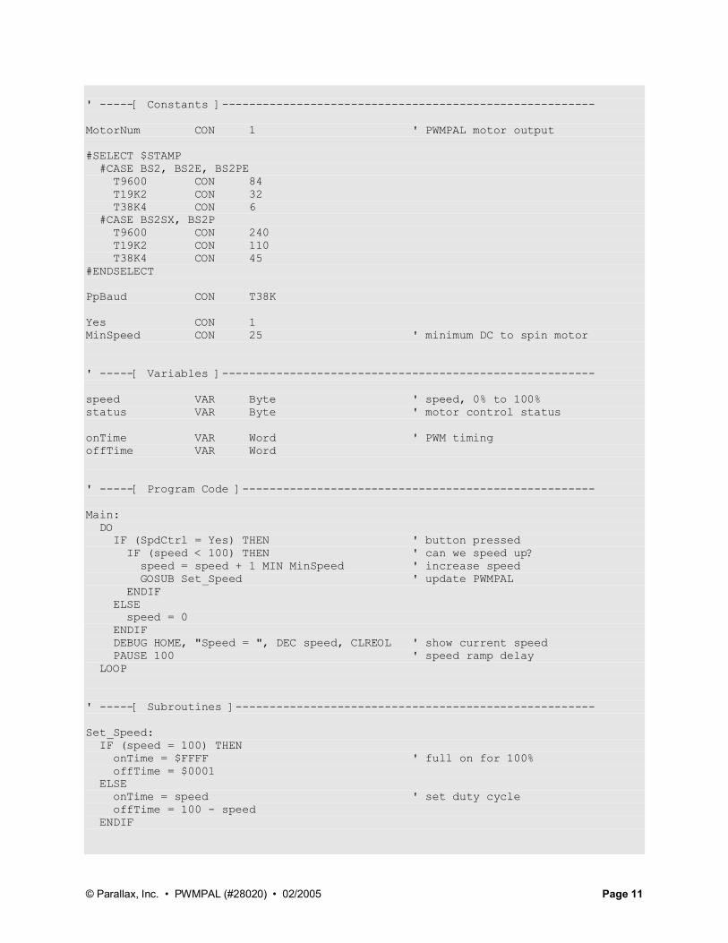
' -----[ Constants ]-------------------------------------------------------
MotorNum CON 1 ' PWMPAL motor output
#SELECT $STAMP #CASE BS2, BS2E, BS2PE T9600 CON 84 T19K2 CON 32 T38K4 CON 6 #CASE BS2SX, BS2P T9600 CON 240 T19K2 CON 110 T38K4 CON 45#ENDSELECT
PpBaud CON T38K
Yes CON 1MinSpeed CON 25 ' minimum DC to spin motor
' -----[ Variables ]-------------------------------------------------------
speed VAR Byte ' speed, 0% to 100%status VAR Byte ' motor control status
onTime VAR Word ' PWM timingoffTime VAR Word
' -----[ Program Code ]----------------------------------------------------
Main: DO IF (SpdCtrl = Yes) THEN ' button pressed IF (speed < 100) THEN ' can we speed up? speed = speed + 1 MIN MinSpeed ' increase speed GOSUB Set_Speed ' update PWMPAL ENDIF ELSE speed = 0 ENDIF DEBUG HOME, "Speed = ", DEC speed, CLREOL ' show current speed PAUSE 100 ' speed ramp delay LOOP
' -----[ Subroutines ]-----------------------------------------------------
Set_Speed: IF (speed = 100) THEN onTime = $FFFF ' full on for 100% offTime = $0001 ELSE onTime = speed ' set duty cycle offTime = 100 - speed ENDIF

© Parallax, Inc. • PWMPAL (#28020) • 02/2005 Page 12
SEROUT PpPin, PpBaud, ["!PWMM", (48 + MotorNum), onTime.BYTE0, onTime.BYTE1, offTime.BYTE0, offTime.BYTE1]
status.HIGHNIB = %0001 << (MotorNum - 1) ' set enable bit status.LOWNIB = %0001 << (MotorNum - 1) ' set control bit SEROUT PpPin, PpBaud, ["!PWMSS", status]
RETURN
© Parallax, Inc. • PWMPAL (#28020) • 02/2005 Page 13
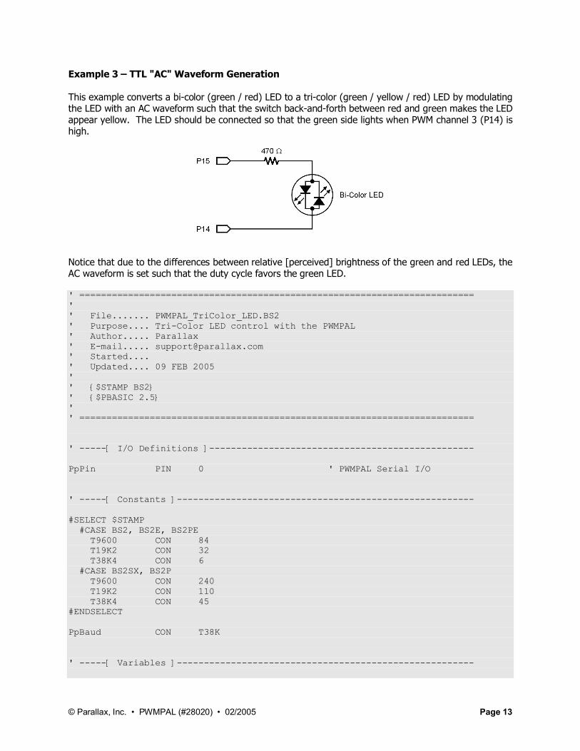
Example 3 – TTL "AC" Waveform Generation
This example converts a bi-color (green / red) LED to a tri-color (green / yellow / red) LED by modulating the LED with an AC waveform such that the switch back-and-forth between red and green makes the LED appear yellow. The LED should be connected so that the green side lights when PWM channel 3 (P14) is high.
Notice that due to the differences between relative [perceived] brightness of the green and red LEDs, the AC waveform is set such that the duty cycle favors the green LED.
' ========================================================================='' File....... PWMPAL_TriColor_LED.BS2' Purpose.... Tri-Color LED control with the PWMPAL' Author..... Parallax' E-mail..... [email protected]' Started....' Updated.... 09 FEB 2005'' {$STAMP BS2}' {$PBASIC 2.5}'' =========================================================================
' -----[ I/O Definitions ]-------------------------------------------------
PpPin PIN 0 ' PWMPAL Serial I/O
' -----[ Constants ]-------------------------------------------------------
#SELECT $STAMP #CASE BS2, BS2E, BS2PE T9600 CON 84 T19K2 CON 32 T38K4 CON 6 #CASE BS2SX, BS2P T9600 CON 240 T19K2 CON 110 T38K4 CON 45#ENDSELECT
PpBaud CON T38K
' -----[ Variables ]-------------------------------------------------------
© Parallax, Inc. • PWMPAL (#28020) • 02/2005 Page 14
state VAR Nib ' LED state
' -----[ Program Code ]----------------------------------------------------
Main: DO FOR state = 0 TO 3 ON state GOSUB Led_Off, Led_Green, Led_Yellow, Led_Red DEBUG HOME, DEC state, " : " SELECT state CASE 0 : DEBUG "Off", CLREOL CASE 1 : DEBUG "Green", CLREOL CASE 2 : DEBUG "Yellow", CLREOL CASE 3 : DEBUG "Red", CLREOL ENDSELECT PAUSE 1000 NEXT LOOP
END
' -----[ Subroutines ]-----------------------------------------------------
Led_Off: SEROUT PpPin, PpBaud, ["!PWMM0"] RETURN
Led_Green: SEROUT PpPin, PpBaud, ["!PWMM3", $FF, $FF, $01, $00] SEROUT PpPin, PpBaud, ["!PWMM4", $01, $00, $FF, $FF] SEROUT PpPin, PpBaud, ["!PWMSP", %01000000] SEROUT PpPin, PpBaud, ["!PWMSS", %11000000] RETURN
Led_Yellow: SEROUT PpPin, PpBaud, ["!PWMM3", $12, $00, $04, $00] SEROUT PpPin, PpBaud, ["!PWMM4", $04, $00, $12, $00] SEROUT PpPin, PpBaud, ["!PWMSP", %01000000] SEROUT PpPin, PpBaud, ["!PWMSS", %11000000] RETURN
Led_Red: SEROUT PpPin, PpBaud, ["!PWMM3", $01, $00, $FF, $FF] SEROUT PpPin, PpBaud, ["!PWMM4", $FF, $FF, $01, $00] SEROUT PpPin, PpBaud, ["!PWMSP", %10000000] SEROUT PpPin, PpBaud, ["!PWMSS", %11000000] RETURN
© Parallax, Inc. • PWMPAL (#28020) • 02/2005 Page 15
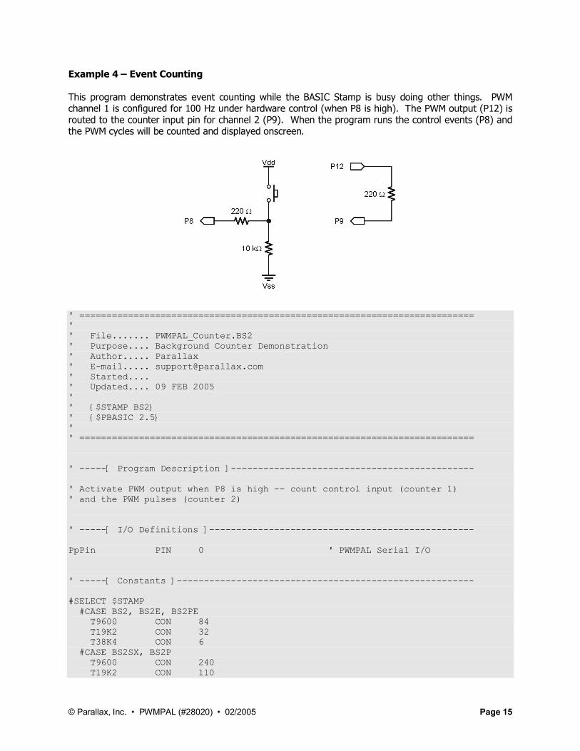
Example 4 – Event Counting
This program demonstrates event counting while the BASIC Stamp is busy doing other things. PWM channel 1 is configured for 100 Hz under hardware control (when P8 is high). The PWM output (P12) is routed to the counter input pin for channel 2 (P9). When the program runs the control events (P8) and the PWM cycles will be counted and displayed onscreen.
' ========================================================================='' File....... PWMPAL_Counter.BS2' Purpose.... Background Counter Demonstration' Author..... Parallax' E-mail..... [email protected]' Started....' Updated.... 09 FEB 2005'' {$STAMP BS2}' {$PBASIC 2.5}'' =========================================================================
' -----[ Program Description ]---------------------------------------------
' Activate PWM output when P8 is high -- count control input (counter 1)' and the PWM pulses (counter 2)
' -----[ I/O Definitions ]-------------------------------------------------
PpPin PIN 0 ' PWMPAL Serial I/O
' -----[ Constants ]-------------------------------------------------------
#SELECT $STAMP #CASE BS2, BS2E, BS2PE T9600 CON 84 T19K2 CON 32 T38K4 CON 6 #CASE BS2SX, BS2P T9600 CON 240 T19K2 CON 110

© Parallax, Inc. • PWMPAL (#28020) • 02/2005 Page 16
T38K4 CON 45#ENDSELECT
PpBaud CON T38K
' -----[ Variables ]-------------------------------------------------------
cntr1 VAR Word ' counter for P8 (switch)cntr2 VAR Word ' counter for P9 (PWM in)
' -----[ Initialization ]--------------------------------------------------
Setup: SEROUT PpPin, PpBaud, ["!PWMM1", $90, $01, $90, $01] SEROUT PpPin, PpBaud, ["!PWMSS", %00010001] SEROUT PpPin, PpBaud, ["!PWMSP", %00000011] SEROUT PpPin, PpBaud, ["!PWMX0"]
DEBUG CLS, "Counter 1 : ", CR, "Counter 2 : "
' -----[ Program Code ]----------------------------------------------------
Main: DO ' get counter values SEROUT PpPin, PpBaud, ["!PWMC1"] SERIN PpPin, PpBaud, [cntr1.BYTE0, cntr1.BYTE1] SEROUT PpPin, PpBaud, ["!PWMC2"] SERIN PpPin, PpBaud, [cntr2.BYTE0, cntr2.BYTE1]
' show counter values DEBUG CRSRXY, 12, 0, DEC cntr1, CLREOL, CRSRXY, 12, 1, DEC cntr2, CLREOL
PAUSE 1000 ' loop delay - Stamp busy LOOP
END
Other Examples
Be sure to check the Parallax web site for the latest updates to PWMPAL application notes and example programs.