q6q the univ nnessee - defense technical information center · iron and better geometry in the...
TRANSCRIPT

Q6Q
The UNIV NNESSEE
department a/ PhusicS
KnoxviHe, Tennessee

MIS REPORT HAS BEEN DELIMITED
MD CLEARED FOR PUBLIC RELEASE
U;DER DOD DIRECTIVE 5200,20 AND
!3 RESTRICTIONS ARE IMPOSED UPON
!. TS USE AND DISCLOSURE,
DISTRIBUTION STATEMENT A
'PPROVED FOR PUBLIC RELEASE;
r-lSTRIEUT JON UNLIMITED.
®- immmmtmimMMMi

}
FINAL REPORT
of
The University of Tennessee Department of Physics Knoxville, Tennessee
on
STUDY OF PNEUMATIC ELEMENTS FOR RADIATION DETECTORS
Work Performed Under Contract N0NR-8ll(0l)
With
OFFICE OF NAVAL RESEARCH
1 May 19$k
Report by: John D. Trimmer, Principal Investigator
KL^UJUi-. . ,g-j

I
Table of Content*
page
I. Project Objectives ......... 1
II. Size of Project Effort . . . . ....« ..- . . . , . 1
III. Summary of Project Accomplishment , 2
IV. Radiation Detection by Indirect Pneumatic Effect 2
The Single Flat-Nozzle Flat-Baffle Configuration U
Other Configurations 6
Conclusions as to Force Measurement . . 7
Conclusions on Portable Radiation Detectors 6
V. Radiation Detection by Direct Pneumatic Effect ........ 9
Energy Considerations 9
The viscosity Bridge 11
Cloud Chamber Devices . 12
VI. Conclusions lU
List of Figures
Fig. 1. Typical Force-Pressure Curve . ; U-A
Fig. 2. Construction of Hark II Meter 5-A
Fig. 3. Full Pasucatic Bridge . - * = 6-A
Fig. k. System with Transverse Baffle Motion 6-A
Fig. 5- Diagram of Viscosity Bridge 11-A
Fig. 6. Cross-section of Flat-plate Transducer i$-A
Fig. 7- Observed Pressure-separation Dependence 15-A
Fig. 8. Hypothetical Nozzle-Coefficient Dependence on Separation . . 16-A
Fig. 9. Theoretical and Observed Force vs. Separation 16-A
Study of Pneumatic Elements for Radiation Detactorg
FINAL REPORT— CONTRACT N0NR-8ll(0l)
I. Project Objectives
Tills is the Final Report on a project initiated April 1, 1952.
originally for a one-year period, but then extended to cover the second
year, ending March 31, 195U- The primary Task Order called fcr experimental
and theoretical survey studies of known means of numerically indicating in-
formation, directed towards "attempts to adapt or devise superior means of
indicating on portable radiation detectors". The first year's survey work
directed attention to possible use of pneumatic elements in radiation
detectors.
A proposal fcr extension of the contract to cover a second year was
therefore formulated, suggesting.a limited continuation of survey study,
but emphasizing primarily the possibilities of pneumatic elements. These
possibilities are two-foldJ the indirect pneumatic effect, in which radia-
tion is first transduced to an electrical effect, which the pneumatic system
is then used to indicate; and the direct pneumatic effect, in which the
radiation exerts directly a measureable effect or. a pneumatic parameter*
such as temperature, pressure, or viscosity.
II. Size of Project Effort
During the year ending March 31, 195U the project was given one-fourth
time by the principal investigator and by Associate Professor James W. White.
A student assistant (Mr. Ted Lundy) was employed full-time through the summer
months, and on an hourly part-time basis during the academic term. Machine
shop time was contributed by The University of Tennessee Physics Department.
Numbered references are given in the Bibliography.
V • .f..

c \
III. 8ammary of Project Accomplishment
The major portion of experimental work was devoted to the indirect
pneumatic effect. This evolved into a study of pneumatic methods of measuring
small forces—i.e., design of a sensitive force-pressure transducer. Such a
transducer, in conjunction with a more or less conventional email-current
electrical meter movement (i.e., a current-force transducer) would constitute
a pneumatic microammeter. The net result of this study is that sensitivity
(and perhapsi other specifications of ruggedness, stability, etc.) achievable
in a pneumatic microammeter appear inadequate for direct, battery-leso indica-
tion in a portable radiation detector. However, results obtained with the
force-pressure transducer are believed to be new, and of value in some fields
of instrumentation, such as pneumatic weighing. A patent application has
therefore been initiated on the force-pressure transducer.
The general problem of optimum design of a pneumatic force-pressure
transducer has been touched only very lightly. A rather wide field of in-
vestigation appears to be open here, with good promise of valuable practical
developments.
Direct pneumatic effects of radiation have been given much less
attention. This does not mean that ultimate possibilities in this direction
are evaluated so much lower; resources of time and manpower were simply not
available for decisive exploration of such possibilities.
In Addition to the rather specific work relating to portable radiation
(2) (3) detectors, more general studies in instrumentation, "N have received col-
lateral support from the project.
IV. Eadiation Detection by Indirect Pneumatic Effect
Radiation detectors often include some auxiliary store of energy, such
as electrical batteries. For portable electronic radiation detectors, bat-
teries at one time constituted a significant fraction of weight and volume of
the total instrument. Development of miniature vacuum tubes (and even more.

3 !
the present active development of transitors) has greatly reduced current
requirements, and new developments in miniature batteries have also been
made. So it has been possible progressively to reduce the total weight and
8i'«e of battery-operated radiation detectors. Perhaps a more serious problem
is presented by battery shelf-life. This is particularly embarrassing for •
civil defense use, where a regular inspection of battery complement might be
* hard to establish.
It is therefore of sane interest to devise battery-less detectors, «
in which all required energy is furnished either by the radiation itself or
by the person using the Instrument. For example, if one assumes the existence
of a transducer, such as the Ohmart cell , which converts radiation to an
electrical current without aid of batteries, one might then attempt either
to indicate the current directly on a super-sensitive meter, or to find some
means of amplifying the currect other than electronic, battery-operated
amplifiers. A possible scheme of amplifying the effect of an electric cur-
rent is the combination of some more or less conventional meter movement, to
convert current into fores, with a pneumatic force amplifier. Power for the
pneumatic amplifier could be furnished by means of manual pumping by the
instrument user.
Industrial pneumatic instrumentation has long made use of devices in
which a small jet of air flowing from a nozzle impinges on a baffle, which *
is movable with respect to the nozzle opening. Our primary aim was to study
such nozzle-baffle configurations for measurement of small forces.
Our work on these possibilities is therefore reported here in the
following order: first, force measurement with a single flat nozzle and flat
baffle, the configuration which we studied most intensively; second, force
measurement with other geometrical configurations; third, our conclusions on
fores measurement by pneumatic means; and fourth, our conclusions in portable
radiation detectors using the pneumatic force amplifier.
••"«••' ' f '•• '-' v"' • • - - -\
'•.' ' ," .>•'":' :• . .': - - " • »'•• .

The Single Flat-Nogzla Flat-Baffle Configuration. Details of this
method are given in Appendix A, with some simple theoretical interpretation.
Results are presented here in the following terms; the force F applied to
a small movable baffle is converted into pressure p, the transducer being
supplied with air at regulated pressure of some fixed value between zero and
20 psi g.
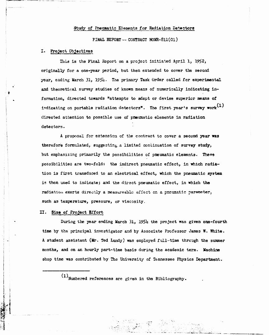
A typical curve of pressure versus force is shown in Fig. 1. Varia-
tion of separation x is also indicated. Both at small and at large x the
force is positive (repulsive). Over a certain range of separation the force
is negative (attractive), and reaches an extreme, -Fm, at the point ma-ked A,
corresponding to an x-value which we may designate x^. At A the slope dp/dF
is infinite, meaning that a very small positive force would cause a noticeable
pressure change. Operation of the system on the branch AB would be unstable,
since positive displacement reaults in more positive force. Operation on the
branch AC; where negative displacement corresponds to increasing force, would I
be stable Over this range the slope of pressure with respect to force is
positive, c' magnitude very large near A and decreasing toward C.
In practical application one would have to insure stability by
limiting the separation to something less than x_, thus ruling out the ultimate
maximum of sensitivity corresponding to point A. In tests made with the
baffle mounted on a flat-strip spring,, cantilever-suspended, a slope of
5 x 10""'1 psi per milligram was observed with good linearity and fair stability
over the range from zero up to 100 milligrams. (Supply pressures 10 psi}
orifice diameter: 0.0lU5ttj nozzle diameters 0.025Kj beryllium copper strip,
0.013 cm x 2.3 cm x 16.£ cv>.) The sensitivity corresponds for one milligram
to more than 0.01 ins. H2O5 this is easily read, for example, on a Model 2l£
Dwyer inclined manometer, which has a five-inch scale for the ran^e 0.10-0-
0.15 ins. B^O. We therefore feel that useful pneumatic devices for weighing
of milligram quantities might well be built along the above lines. I !
•
! I
'I i I
•«••. 4,, •_, • i
B
I
.
Fig. 1. Typical Force-Pressure Curve.
U-A
: '--t,^
.'..,/•

5
Two models, designated Mark I and Mark II, or electric meter movement
•were built and tested as adaptations of the fiat-baffle force-preasare tre.os-
ducer to measurement of small currents, Both are of the moving-iron type and
are very much the same, except that Mark II features more carefully treated
iron and better geometry in the magnetic circuit, and a specially-wound coil.
Fig. 2 is a drawing of itark II.
» Because delivery of the special coil was delayed for so long, a pre-
liminary test was made wi;h the Stark II meter, using a coil of 120 turns.
With 0.2 amperes, or 2U ampere-turns, a pressure change of 5.1 ins. Hg was
observed, supply pressure being 10 psi. This is a sensitivity of 2.9 ins.
H2O per ampere-turn. After the 215,000-turn coil was finally received, we
were unable in the time available to duplicate this sensitivity at low current,
within a factor of the order of ten—i.e., our best sensitivity was more like
0.3 ins. H9O per ampere-turn. The discrepancy can doubtless be ascribed
to the following two factors:
1. The first measurements (with the 120-turn coil) were made on a
half-bridge—the nozzle in series with an orifice, with gauge
pressure being read on a vertical mercury manometer connected
between orifice and nosale. The later measurements were made on
a full bridge, as shown in Fig, 3 = The sensitive differential
manometer was difficult to keep on a fixed scale position by ad-
justment of the valves V-, and Vp, and consequently estimates of
deflection due to electric current were rather badly masked by
manometer drift,.
2. The iron in the magnetic path had been subjected to 2k ampere-
turns in the preliminary test. Subsequent demagnetization with
alternating current of diminishing magnitude was not carried out
to less than 1 ampere-turn. Hence it is probable that in the
JF later tests the iron was not of as high initial permeability as
... ;• •; V-
•'»•: 'i. ' ,,-. '. • :• .; ' '"'••••:'•

tt
r A
S/C
Y
C * /» I*' • 1%f •* — i-
C — coil of 215,000 turnsj 130,000 ohms; No. I4O wire R — magnet core rod, 0.5" diam. 7 Armco Magnetic Ingot Iron, T — magnet yoke, 0.5" x 0.625" ( nitrogen-annealed B — baffle, 0.375" diam » (0.010" diam. stainless steel
centering pin on baffle) N — brass nozzle structure, tapped for air connection, with 0.025s
diam. nozzle opening S — screw for adjusting noszle-baffle separation
Fig. 2. Construction of Mark II M»ter.
A.

6
in the first tests, immediately after heat treatment.
It is clear that both these limitations could be overcome oy more
careful, extensive work. Incentive for such work remains weak, however,
until there is clearer evidence that electric current measurement is a use-
ful direction in which to apply pneumatic force measurement.
Other Configurations. In addition to the single fiat-nozzle, flat-
» baffle configuration, a number of other geometrical arrangements were con-
sidered. These included arrays with two nozzles more or less opposed to
each ether, devices in which the baffle motion was across, the jet axis
instead of along it, and various shapes cf curved nozzles or baffles. So
far as the general problem is concerned, of finding optimum designs for
pneumatic force-pressure transducer?, we feel that we have barely scratched
the surface. The possibilities to be tried are practically endless, so a
good theoretical critique is invaluable. Since the flat geometry was the
only one into which we had a reasonable theoretical insight, no other con-
figuration was given systematic study.
The most interesting and promising of these subsidiary experiments
featured the pointer of an ordinary panel microammeter movement, mounted
beneath a conical nozzle so that pointer movement was across the jet axis.
See Fig. u- This simple sketch does not fully disclose the exact aero-
dynamic shape of the pointer tip, which in the broad, heart-shaped portion
has a slight downward curvature toward the edges. Also the ridge of the
stem portion extends somewhat into the heart-shaped portion. These details
are probably much less important than the exact shape of the tip, since the
nozzle was mounted above the narrowing tip portion.
By careful adjustment of the vertical separation between nozzle and
pointer tip to a very small value (not accurately measured), and with an
air supply pressure of only 0.5 psi, application of 0.5 na gave pressure
change corresponding to sensitivity of 0.021* psi mg"1. This was with a full

6~A
fissure U
orLjLc&s
fcf nozzle • biff I
£&^er*r»f/«.| press art
n*
M jVee )i02Z,((
Fig. 3. Full Pneumatic Bridge
i
A
t±3
I
io2.7J< no
* */ SCd/e: £> « J
m
Fig. U. System with Transverse Baffle Motion.
S^ *<J»a
arc of l»wfcr Vn«i#*i
>. ..•.,.- •••• ' ••.•"*.
• — - -a L_L ^»_, •>••••<

.
7
pneumatic bridge with 0*013|>" diameter orifices and with differential pres-
sure read on an inclined manometer.
Conclusions aa to Force Measurement. Though the work described in
this report is far from exhaustive, we do feel that the possibilities of
pneumatic force-pressure transducers have been investigated to the point
where pros and cons may be tentatively summarized.
In favor of further development of such transducers, it may be said
that by straightforward procedure (use of commercially available pressure
regulators, valves, manometers) and a small amount of fine machine work
(drilling of orifices and nozzles, fabrication and suspension of baffle) it
is possible to demonstrate fast and reasonably accurate measurement of
forces in the milligram range. Since this result was established with a
relatively small effort, it seems reasonable to expect that a more careful,
prolonged study would yield noticeably superior performance.
The principal difficulty revealed by our work is the general problem
of baffle suspension. Ideally, this should be frictionless, independent cf
orientation with respect to gravity, and permitting easy application of the
for^e to be measured. The nature and importance of these requirements will
vary with the type of measured force. Permanent vertical orientation would
not be unduly restrictive for laboratory weighing but would be intolerable
in a portable electric meter. Vertical orientation permits aerodynamic
suspension within certain limits of total weight. For example, in our flat-
baffle experiments the baffle weight of about 0.5 gm was supported against
gravity by the Bernoulli attraction. For weighing milligram quantities of
most materials it would not be unreasonable to keep the balance pan weight
below G»5 gm.
Even with aerodynamic suspension there may be need for guide pins
or other stops to limit lateral motion of the baffle, and thus some danger
of sticking friction. It may be possible to provide lateral stability by
:-«''** .•*-*•• .•-.•• j. i»r, *• ..' -> i •

! 8
aerodynamic furuwo as, for example, with » onhoHra; ball (baffle) inside
an inverted conical funnel (nozzle).
For applications .there permanent vertical orientation is not
acceptable, various forms of pivoted or elastic suspensions may be con-
sidered. Since the necessary displacements are very small, purely elastic
suspension seems useful. For measuring very small forces, the spring
stiffness of the elastic suspension must be correspondingly small. Further,
the suspension must provide highly accurate positioning of the baffle rela-
tive to the nozzle. Requirements appear, however, to be within the abilities
of modern instrument-making art.
Conclusions on Portable Radiation Detectors. Typical portable
radiation detector specifications call for full-scale ranges of 0.25 up to
500 roentgens per hour. This corresponds, in one gram of air, to currents
-11 — ft of 1.8 x 10 up to 3.6 x 10~ amp. So one might say that currents to
be measured are in the general range of hundreds of micromicroamperes. The
Model RT Ohmart cell, for example, is described by the manufacturer as
generating 1 x 10 amp for 1 mr hr from a Co-60 source. To be useful,
a b itteryless detector operating from such a cell would therefore need to
furnish readings of currents as small as some 10"1 amp. This is two
orders of magnitude bslow the best sensitivity we demonstrated (£ x 10~"
amp) with a complete pneumatic meter. However, as mentioned in preceding
sections, we concentrated more on force measurement than on current measure-
ment.
In addition to the problem of sensitivity, which is important both
in laboratory and in portable instruments, the requirement of portability
imposes other requirements. Our experiments on pneumatic force measurement
with the fl«t-baffle system required pressure-regulated air flows of the
order of 20 std. car sec J". Provision of this flow in a portable, manually-
pumped system would be a formidable problem. However- the transverse-motion
;£V. :£ •••: • • £,•*" T

1 i i
baffle gave promising results with only 0.5 psig pressure supply (compared
to 10 psig for the flat baffle) and correspondingly smaller flow (not
measured), so that the portability requirement is much less severe.
In summary, the three requirements of sensitivity, stability, and
portability proved to be more than we could meet in a finished, complete
portable radiac with indirect pneumatic indication. We would consider it
premature to say that these requirements could not possibly be met. par-
ticularly if the promise of the transverse baffle experiment is not
illusory.
V. Radiation Detection by Direct Pneumatic Effect.
The full picture of the interaction of radiation with matter is
quite complex. Ionization and photoelectric effect are doubtless the two
actions most generally important for radiation measurement. In looking
for possible direct effects of radiation on pneumatic parameters it is
therefore natural to start with ionization of gases. In fact, practically
all the possibilities me have considered are based on ionization as the
fundamental process. The work to be reported here is entirely of a survey
nature. None of the possibilities was reduced to practice. The following
presentation gives first some general energy considerations and then a
brief discussion of the more interesting avenues of development that appear
to be open. This section may be summarized in the statement that direct
pneumatic effects of radiation constitute an area of some general interest,
though not resulting at this time in any concrete proposal meeting porta-
bility requirements.
Energy Considerations. Every indicating instrument converts an
•input" energy change, representing some interference with the measured
quantity, into an "output" energy change, associated with an observable
scale reading. This conversion may or may not include power amplification,
depending on the input power level compared to the desired speed of response
» -tr
k^*-:^.

•
10
and energy level of output indication. For radiation detectors the input
power is that delivered by radiation absorbed in the instrument.
The "average" input power level of radiation detectors may be taken
as the 83 erg hr corresponding to 1 roentgen hr~ , or 0.023 erg sec" .
For comparison with this power level, we may take the energy stored in
full-scale deflection of a panel microammeter (Simpson Model 26, 2$ micro-
amp., our Code No. A-101; cf. p. 9, ref. 1). With a spring rate of 7.33
erg rad and full scale deflection of 1.75 radians, the energy is 11 ergs.
2 In addition there is the I R loss in the 2100-ohm coil, which amounts to
13 erg sec" . This comparison shows clearly the power amplification needed
for this kind of indication.
The ultimate low level of powerrequired for indication would be
represented by the spinthariscope used with a fully dark-adapted eye. A
1 mev particle converted at full efficiency would give some 5 x 10' photons,
of which only about 7 would be needed for the eye to see. Even allowing
for very low efficiency, it would seem probable that each "counted" particle
would give a visible indication. So this is an example requiring no power
ampiiiication.
It is interesting to compare scintillations, visible only in the
dark, with cloud chamber tracks, visible only under good illumination.
Both are directly (i.e., without further amplification) visible, but it
must be noted that the track occurs only because of energy previously
stored in the supersaturated vapor. Thus the cloud chamber involves a
kind of (discontinuous) power amplification.
For a portable radiation meter the requirement must be met of
readability under ordinary ambient illumination. The foregoing examples
suggest that this can be accomplished only by provision of power amplifica-
tion of the order of 500.
During the course of this project some cursory thought was given to
-:.L; _.•&;,_

••-
11
a considerable variety of ideas for radiation detection. Requirements of
portability, manual (battery-less) operation, and limitation to pneumatic
effects, reduced the number considered to fall within the scope of the
project; and energy considerations served further to eliminate all but the
relatively few ideas developed in this report.
The Viscosity Bridge. One mechanism by which radiation might con-
ceivably affect a pneumatic system would be by changing viscosity of the
gas. Sufficiently sensitive measurement of differential pressure drop
across two porous membranes, identical except that only one is subject to
radiation, might serve for radiation detection. This idea was tested in
the form of a viscosity bridges, sketched in Fig. $. Only a limited test
of this device was carried out, principally because of the hazards in using
the polonium source. (The method of clamping the source in place was not
carefully enough worked out, and the protective film was broken.) It was
planned to test both metallic and non-metallic porous diaphragms. Only
the non-metallic (Corning fritted glass) were tested.
With supply pressures up to 20 psig and with a wide range of
por'city of the glass diaphragms, no detectable effect was found. Since
the non-metallic discs seemed a priori more favorable, there was little
incentive to use the limited available time for further testing ox this
approach.
Studies ' are available which show that the average ion density
to be expected would be no more than lO* ions cm"-' per disintegration, with
spacing such as we had—about 1 inch. Our source, furnished as 35 milli- Q
curie, presumably furnished in the half spate some 10 disintegrations per
second. With the geometry and flow rates of the viscosity bridge, this
puts an upper limit of some 1011 ions esT^ for the air flowing through thu
irradiated membrane. Since there are in standard air 2.7 x 10-^ molecules!
-3 ° ciii , the relative ion density could scarcely be more than one in 10".
v. ' ..'7 ••.;•'-.:. * :-•-• •. --<<•

s &-
Mill •• I
H—f-
radUo/tlon
0,0« - M,M'
D W
— orifices — porous membranes — differential pressure gauge — window to admit radiation
Fig. 5° Diagram of Viscosity Bridge
11-A
X air
D A VA
-j
•• -•- • "••*•-- =

!• i
12
The 6ffect per ion en viscosity may be estimated from theoretical
and experimental consideration of ion mobility. At given temperature the
mobility is proportional to the mean free path, X^, of the ion in the gas.
At given pressure and temperature, viscosity is proportional to mean free
path. Bence the effect per ion en viscosity would be determined by the
value Tu relative to X , the mean free path of neutral gas molecules.
The example of oxygen^' suggests that \± is something like half of X .
Bence the ions would have u relative weight of about two in the direction
of diminishing the viscosity coefficient. This factor of two does not go
far toward overcoming the low relative ion density deduced in the preced-
ing paragraph.
There is perhaps some chance that a porous membrane material might
be found that would itself be subject to some radiation effect which
would interact cumulatively with ionization of the gas so as to give a
larger apparent change of viscosity. This would not be, strictly speaking,
a pneumatic effect) and, in summary, one must say that the effect of
radiation on viscosity does not seem a promising direction is which tc
look for a useful direct pneumatic effect.
Cloud Chamber Devices. If one broadens the concept of pneumatic
effects to include condensation and evaporation, the cloud chamber may be
regarded as a possible means of exhibiting directly the effect of radia-
tion c
For example, a commercially available piece of deaions tration
apparatus (Cenco-Knipp Alpha Ray Track Apparatus, Cenco Catalog No. 712U5)
provides the pattern for a possible radiation detector. This device is
simply a small, manually-operated cloud chamber, with a speck of alpha-
emitter permanently mounted to one side. Replacement of this known
emitter by a sample to be counted would permit at least crude measurement
by visual observation of the number of tracks. It is true that a direct
• •• • •••>'•• . - .- ..••••. , • ..>-._,/.:f_,V- . - V

13 !
voltage of 100 to 200 volts must be supplied to this apparatus to sweep
charged particles from previous expansions out of the way, and so it does
not entirely represent a manually-operated instrument. But more funda-
mental than this is the limitation that visual estimate of track numbers
(or other factors such as number, size, rate of fall of droplets) does
not constitute a good basis for quantitative measurement. Photoelectric
(8)(9) conversion to a meter reading is possible for soaw effects
One might hope to achieve quantitative indication from the cloud
chamber effect by a differential arrangement of two chambers, with only
one subject to radiation. Thus we postulate two identical chambers,
except that in one a certain extra condensation takes place upon expansion
because of the ionization left by radiation. This extra condensation has
two effects^ 't a reduction of vapor pressure (and, to that extent, of
total pressure) and an increase of temperature, due to heat released by
condensation of vapor. Thus measurement either of differential pressure
or differential temperature between the two chambers might serve as indi-
cation of radiation.
Unfortunately, the pressure and temperature effects appear +o
interfere substractively rather than additiveiy. However, a more careful
study, both theoretical and experimental, of the time-dependence and
magnitude of temperature and pressure changes is needed before the true
potentialities of this approach can be estimated. Such a study would
seem to be of basic value to understanding the cloud chamber in many oS
its applications.
Measurement of pressure or temperature has the advantage over any
visual observations of tracks that it averages, more or less instantaneously,
'.& ^;v,-v;^': *'

Hi
over the whole chamber volume, and thus does not reflect just a localized
radiation effect.
VI. Conclusions
Work supported by this Project may be continued in The University
of Tennessee Physics Department along two lines: (l) exploitation of
pneumatic measurement of small forces; (2) response of the human eye to
time-dependent visual stimuli, particularly relating to intensity and to
polarization. Emphasis given to the first will naturally depend largely
on the outcome of the patent search, since it would be predominantly an
industrial development. Emphasis on the seccnd will reflect a long-range
interest of Department staff members.
It is also our hope that investigators at other universities and
research establishments may find in the work we have reported the begin-
nings of worthwhile further effort.
c3fe $ -•••• :.*, ••••.'•• . ".-.• • • .- • . •••• „v".
•/J-^-. • •• • ••••'•• :>','-:^\- • '

! ! 15
Appendix
Theory of Flat-Nozzle Flat-Baffle Transducer
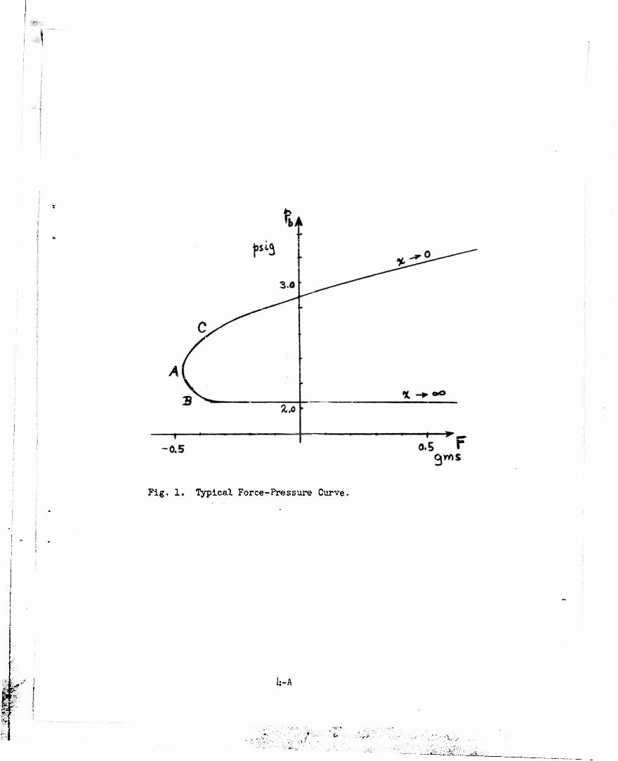
The genera}, principle of this device may be explained with reference to
Fig. 6. Incoming air from a pressure-regulated supply flows first through
a fixed orifice and then through the nozzle and along the movable baffle io
the atmosphere. Under these conditions the batk pressure p^ will be a sen-
sitive function of the separation x. The force required to maintain the
baffle at a particular separation and the relation of this force to the
measured back-pressure are the objects of this study. In particular, an
effort is made to predict the force-separation curve. This is a semi-
empirical treatment, with primary emphasis on obser ed experimental results.
The observed relationship of force end back-pressure has already been
displayed in Fig. 1. The problem now ia to analyze this overall relation into
its two componentsi the relation of force F to separation xj and the relation
of back-pressure p. to separation x.
If the symbols p *nd p. represent gauge pressures and if Q represents
volume velocity of flow, it seems reasonable to represent the pressure drops
across the orifice and the nozzle-baffle by the equationst
PB - Pb - k0Q* (1)
Pb-M n (2)
in which k and k are resistance coefficients of the orifice and of the o n nozzle-baffle configuration respectively. The latter naturally depends on
the separation, so that
^ ' *»Cx> (3)
Eliminating $ from (1) and (2), we have
Pa 1 • CkoAn) (U)
tUmfi *ffl»l •- <|tt j
-
15-A
input air on pat <*<»' —\ (uftlunne f*u) velati-Kj Q. a*t \ . negw. Jetted pir«ssav« fcj H T
c\>^ m*ft orifice.
Fig. 6. Cross-section Diagram of Flat-plate Transducer.
• • 1 • 1 » \ r-
9 0,61 »•«• a'03 *••!
1 ' ' '—T**. cm
Fig. 7. Observed Pressure-separation Dependence.
'•••-•'. •••• •• • '"-,"^—
(•.••I •:'-• ft . -

16
or conversely,
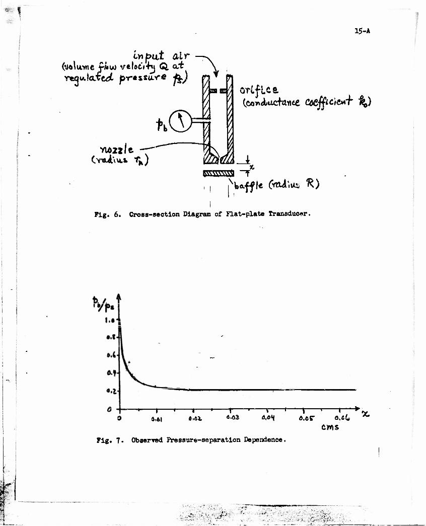
£n m Pb/Pa (5) *o 1- (PJ/PB^
?b* observed dependence of Pw/pg on separation x is as shown in Fig. ?•
The corresponding dependence of kfAo* according to Bq. (5), is given in
Fig. 8. Using this as basis, one can attempt to replace Eq. (3) by a specific
formula. The form suggested by Fig. 8 is
(No great effort was put into fitting a formula to the curve of Fig. 8—
all that is needed is something that will illustrate the further procedure.)
Let F denote the force on the baffle and let F* denote the approximation
to the force which might be achieved by neglecting viscosity. Then F*" would
involve two terms; a downward force representing rate of change of momentum,
and an upward force due to Bernoulli effect. Thusi
F* " *&) " 1 (^Pv2) ' ^^ (7)
where p is density (assumed constant, kach numbers being no more than one-third),
and An - *rn2.
Substituting v - Q/2nrx into Eq. (7) and integrating yields
** - **£.- 3gg*) CM If n - 2 in Eqs. (l) and (2), then
2' Ps , % Ko Kn
and Eq. (8) becomes
Ko ̂ fe-W
gfcftSfl v: •% y : •%•'•
lo-A
"I 1 1" i i—»—i—t »»
cms Fig. 3. Hypothetical Nozzle-Coefficient Dependence on Separation.
i
I*' ft
M. —i—^g—*r* r "*<— *i"—i—-i 1—
«*" <?.o2. o.a«f ^
/ * ^ observe^ bo'iKTS
Oak * *• cms
/(*o-JW.I a.4 X»e)
Fig. ?. Theoretical and Observed Force vs. Separation.
i-1*..—_*!__..

m
Define
F - PPs o n
I i
>.L
i?
(ID
This is the force which momentum change would exert if through An issued the
1/2 full volume flow (pgA0) which pa could force through the orifice alone.
Introducing Fno and kn from Eq. (6), into Eq. (10) gives
il - •"^•VP7 I (12) ^no'"- ' ""•no *n7" (l*kno)x
m+BknJ'
baffle on one arm of an analytical balance for force measurement. Separation
was measured by an optical lever working from the cross-beam of the balance.
(The set-up used for these measurements differs from that of Fig. 6 in that
the baffle and nozzle were not of the seune diameter—the nozzle was of $/M> in.
diameter and the baffle was 1 l/u in., in diameter. See discussion of numerical
values below.)
Although the agreement between theory and experiment displayed in Fig. 9
is not impressive, it is about what can be expected from the derivation of
En. (12) and from the gross estimate of viscosity effects. The important
point Is that the shape of the force-separation curve was correctly guessed
a priori, then determined experimentally, and finally understood at least
. i«*??,.--V4'.- $0?••• .- • •••••• '.•'.; •,-. • -i~.- .-Xrs; -.-•'-:
This is used in plotting the broken curve of Fig. 9, with m - 2,
B - 10"^ cn^ QJJJJ ^ • 2.60. Since viscosity was neglected in deriving
En, (12), it is to be expected that the total force F will differ from F*,
and that the difference will approach, at x » 0, a positive (repulsive) force
of magnitude A^g. The solid curve of Fig. 9 is an estimate of the way this
correction might add to the other effects.
A typical set of observed values of F vs. x are also plotted on Fig. 9.
Many such measurements were made, for various values of p8 and for different
I orifice and nozzle combinations. Measurements were made by supporting the
• ,--i\ _.: - •'••*• •r-'Ll

«
%
18
qualitatively from the theoretical side.
Numerical values used for Fig. 9 are as followsi r - 0.0125 in., n
l^(R/rn) - 3.0, p - 1.2 % 10-3 gm.cnT3, p - 6.89 x 10* dyne on"2. This 8
giVB8 Fno " 198 dynes* *nP8 - 2.18 x 10³ dynes, corresponding at x - 0 to
(^nPe/^no' " 1*»0« The value of ln(R/rn) is a guess as to the proper value
to represent the large baffle diameter, but the choice is not sensitive—
baffle diameter ranging from 3/8 in. to 1 1/1* in. gives ln(H/rn) ranging
from 2.71 to 3.91.
In review of the entire effort represented by this appendix, it
appears that better theoretical interpretation of experimental results
would call for two kinds of Improvement over our works (1) improved
measurement, particularly more systematic measurement of flow rates; and
(2) more careful theoretical approach to such matters as the assumptions
basic to Bqs. (1) and (2).
I • •
v- •; .••/->-.••••*• '.-... 3?<$U-3
.-__•• -i; safes I i—la — ^-jJn-t-i-5"- • 1 atafcls—•-

1
19
Bibliography
1. J. D. Trimmer, "Indicating Methods for Portable Radiation Detectors", First Annual Report on Contract Nonr-8ll(01), Knoxville, Tennessee, May 1, 1.953.
2. J. D. Trimmer, "Taxonomy of Man-made Objects", JOUR. TENN. ACAD. SCI. 28, 279 (1953).
3. J. D. Trimmer, "The Basis for a Science of Inctnimentology", SCIENCE 118, U61 (1953).
It. P. E. Ohmart, "A Method of Producing an Electric Current from Radio- activity", Jour. Appl. Phys. 22, 150U (1951).
5. R. W. Nichols, "The Ioaiaatien in Air Maintained by a Uniform Plane Circular Distribution of Radioactivity", Am. J. Phys. 22, 59 (195U).
6. P. A. Frtiser, "The Ionization Maintained in a Oas Before a Thin Plans Uniform Circular Source of Ionising Particles", Am. J. Phys. 22, 220 (195U).
7. J. A. Crowther, IONS ELECTRONS AND IONIZING RADIATIONS, Edw. Arnold and Co,, London, 8th Edition, 19U9; pp. 2U-2$.
8. "Condensation Nuclei Meter", General Electric Review 57, 19 (January, 19Sli).
9. P. J. Nolan and L. W. Pollak, "The Calibration of a Photoelectric Nucleus Counter", Proc. Roy. Irish Acad. 51 (Sect. A), 9 (19U6).
10. N. N. das Gupta and S. K. Ghosh, "The Yilson Cloud Chamber and Its Applications in Physics", Rev. Mod. Phya. 16, 225 (191A6).
.-.•
• -~'- • •••••• " • sti • ':••--.•- hsSfemfsM