qa engineering manual - june- · particulate, smoke and odor from the kitchen exhaust air stream....
TRANSCRIPT

AIR PURIFICATION UNIT - APU
Grease, Smoke, and Odor Abatementfor Commercial Kitchen Applications
Wallenstein, ON N0B 2S0
Phone: 519-669-0238www.q-asales.com
Engineering Manual
7212 Line 86, PO Box 4


An Introduction
The Ecology APU offered by Quiet‐Aire® utilizes a three‐stage filter system and is available in a
variety of configurations to meet engineering design requirements for the elimination of grease
particulate, smoke and odor from the kitchen exhaust air stream. Integrated or stand alone
modules are available for the blower, filter and odor control functions of the system.
Installation can be in the ceiling space above the kitchen exhaust hood, or in a remote location
such as a mechanical room, or on the roof. The Ecology APU provides the food service operator
an economical solution to problems, which in the past may have prevented the installation of a
commercial kitchen. Our units are available in models to cover any CFM range between 1,100
and 40,000. All Quiet‐Aire® APU models are and Listed and meet all requirements of
NFPA 96, the local authority having jurisdiction and national building codes.
Ruggedly constructed, yet uncomplicated in design, the Quiet‐Aire® Ecology APU is an essential
piece of equipment that will complete your cooking operation.
ETL ETL C

Page
Overview . . . . . . . . . . . . . . . . . . . . . . . . . . . . . . . . . . . . . . . . . . . . . . . 1
Product Description Codes . . . . . . . . . . . . . . . . . . . . . . . . . . . . . . . . . . . . . . . . . . . . . . . 3
Operation . . . . . . . . . . . . . . . . . . . . . . . . . . . . . . . . . . . . . . . . . . . . . . . . . . . . . . . . . . . . 4
Dimensions & Performance Data. . . . . . . . . . . . . . . . . . . . . . . . . . . . . . . . . . . . . . . . . . . . . . . . . . . . . . . 8
Attributes & Filter Schedule . . . . . . . . . . . . . . . . . . . . . . . . . . . . . . . . . . . . . . . . . . . . . . . 16
Shipping Dimensions . . . . . . . . . . . . . . . . . . . . . . . . . . . . . . . . . . . . . . . . . . . . . . . . 17
TABLE OF CONTENTS
right to alter the goods and the specification of the goods represented within this Manual
Publication Date Oct 10, 2013
Wiring Diagram . . . . . . . 19. . . . . . . . . . . . . . . . . . . . . . . . . . . . . . . . . . . . . . . . . . . . . . . . . . .
Product Bid Specifications . . . . . . . . . . . . . . . . . . . . . . . . . . . . . . . . . . . . . . . . . . . . 22
Through our on-going program of product development, Quiet-Aire Sales Inc. reserves the

1
The Ecology APU is available in a variety of configurations to
meet engineering design requirements for the elimination of
grease particulate, smoke and odor from the kitchen exhaust
air stream. Integrated or stand alone modules are available for the
blower, filter and odor control functions of the system. Installation
can be in the ceiling space above the kitchen exhaust hood, or in
a remote location such as a mechanical room, or on the roof. The
Ecology APU provides the food service operator an economical
solution to problems, which in the past would have prevented
the installation of a commercial kitchen. Ecology APU solves the
problems associated with the following:
NEW HIGH-RISE BUILDINGS
Ecology APU provides the economical solution to the cost of
running expensive 16 gauge, all welded fire rated ductwork to the
roof as required by Fire and Building Codes. The cleaned kitchen
exhaust air from the Ecology APU unit can be exhausted out of the
side of the building at usually 10’ (3 meters) above ground level or
into an adjacent covered parking area.
NON TRADITIONAL SITES
Ecology APU provides the solution for historical and architecturally
protected buildings, where the installation of a restaurant kitchen
was not possible at the time of design.
MALL OPERATIONS WITH FOOD COURTS
Ecology APU provides pollution control for new and existing Mall
Food Court operations and the fexibility for future expansion of the
system. Multiple hoods and APU filter sections can be joined to
common odor control and blower sections of the system.
KITCHEN EXHAUST ODOR ABATEMENT
Ecology APU will effectively control the objectionable odors
produced from commercial cooking operations when equipped
with the optional Odor Control Section. This option addresses the
problems of commercial kitchens located near residential areas or
areas that are under pollution control requirements from the local
Air Quality Management District or other local authorities.
REDUCED DUCTWORK COST IN CANADA In Canada (ETLC
Listing) and some cities in the United States, authorities allow
exhaust ductwork downstream of the Filter Section to be installed
using standard HVAC duct.
OVERVIEW Air Purification Unit

PRODUCT SPECIFICATIONS Air Purification Unit
2
OVERVIEW
1
DESCRIPTION & O PER AT IO N
4567 3 2 1
ODORSPRAYCABINET
CHANNEL BASE
AIR
FLOW
9
SOUNDPROOFING INSULATION
4867 3 2 1
CHANNEL BASE
AIR
FLOW
9
SOUNDPROOFING INSULATION
TYPICAL ARRANGEMENT VIEWS SHOWING MAJOR COMPONENTS(OTHER ARRANGEMENTS & CONFIGURATIONS AVAILABLE)
Figure 1- SIDE ELEVATION OF UNIT WITH OPTIONAL ODOR SPRAY SECTION
Figure 2- SIDE ELEVATION OF UNIT WITH OPTIONAL ODOR ABSORBING
MEDIA TRAYS
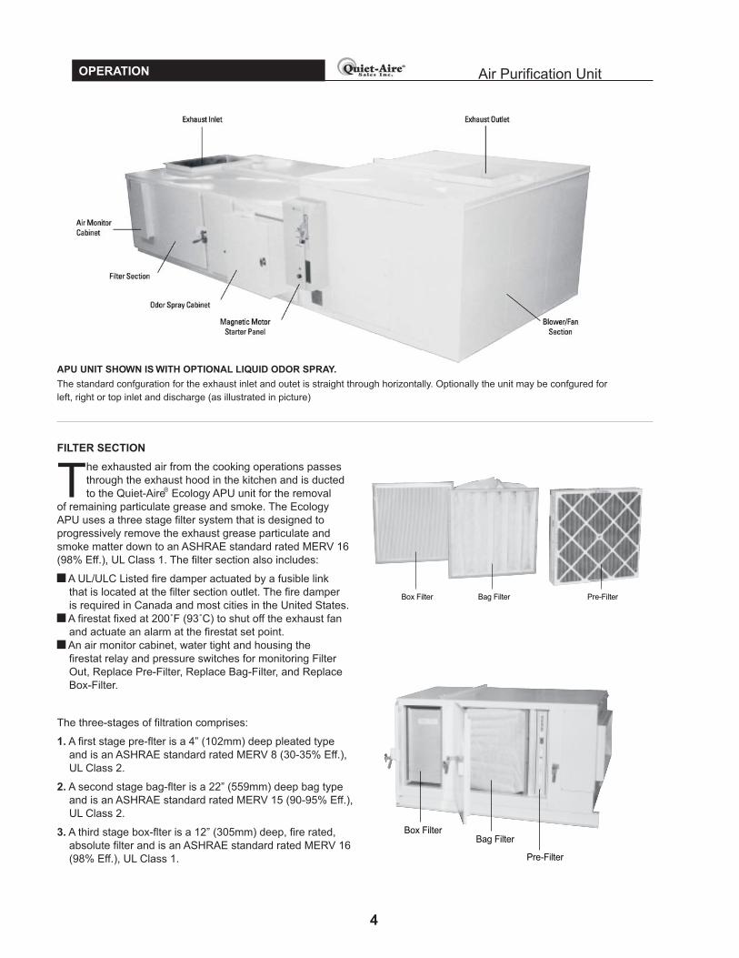
1 Air monitor cabinet
2 Pre-Filters - ASHRAE STANDARD rated MERV 8 (30-35% Eff.), UL Class 2
3 Bag Filters - ASHRAE STANDARD rated MERV 15 (90-95% Eff.), UL Class 2
4 Box Filters - ASHRAE STANDARD rated MERV 16 (98% Eff.), UL Class 1
5 Odor spray assembly section (optional)
6 Fusible link fire damper
7 Combination magnetic motor starter
8 Odor absorbing media section (optional)
9 Blower/fan and motor section
(integral shown or remote mount)

PRODUCT DESCRIPTION CODES
3
PRODUCT DESCRIPTION CODES
Quiet-Aire® Ecology APU’s are identified by a series of letters and numbers which designates features.
1._______ 2._______ 3._______ 4._______ 5._______ 6. ______ 7. _______ 8._______SERIAL DESIGNATION:
Explanation of Codes:
1. Filter Section
APU..................The Basic Filter section which includes: Pre-Filter, Bag Filter, Box Filter, Fire Stat, Air MonitorCabinet, Status Panel, and Filter Enclosure Cabinet/Housing with Fire Damper.
2. Unit Size
3. Odor Abatement Option
OS ....................Odor spray indoor/outdoor style cabinet(s). (1 cabinet APU-15 and smaller, 2 cabinets APU-18 & larger)
HS ....................Heated/Insulated odor spray outdoor style cabinet.
OT ....................Odor media trays filled with alumina spheres impregnated with potassium permanganate and
activated carbon.
4. Exhaust Fan Section
FIS ...................Indoor Fan Section with Sound Insulation Package and a Combination Magnetic Motor Starter
housed in a TYPE 1 General Purpose Indoor Cabinet.
FOS .................Outdoor Fan Section with Sound Insulation Package and a Combination Magnetic Motor Starter
housed in a TYPE 3R Raintight Outdoor Cabinet.
5. APU Status Panel
ACW - HOA.......Is used in conjunction with a separately controlling fan circuit, and consists of the following: NEMA 4X
Cabinet, Fan On Light, Power On Light, Filter Out Light, No Air Flow Light, Fire Light, Replace Pre-Filter Light,
Replace Box-Filter Light, Replace Bag-Filter Light, Alarm Buzzer, Buzzer Mute Push Button,
Relays, Timers, Control Transformer, and Terminal Blocks. The H.O.A. feature (Hands-Off-Auto) is a
manual selector control, built into the status panel for remote control by building automation system.
ACW .................This unit consists of the same parts as the ACW-HOA except there is no H.O.A and the only
6. Fire Suppression
APP ...................Ansul fire suppression pre-piping done at our factory.
X .......................No fire suppression.
EXAMPLE: A (APU–10–OS–FIS–ACW-HOA-APP-UV-VFD) is a Quiet-Aire Ecology Indoor APU sized for 10,000 CFM nominal;®
includes a fiter section with liquid odor spray, a sound insulated indoor fan package, a remote control panel with, hand-off-auto,
feature, Ansul pre-piping, UV application, and VFD.
APU Model Number CFM Range
02 1,100 - 2,000
03 2,100 - 3,000
04 3,100 - 4,000
05 4,100 - 5,000
06 5,100 - 6,000
08 6,100 - 8,000
APU Model Number CFM Range
10 8,100 - 10,000
12 10,100 - 12,000
15 12,100 - 15,000
18 15,100 - 18,000
20 18,100 - 20,000
24 20,100 - 24,000
APU Model Number CFM Range
28 24,100 - 28,000
32 28,100 - 32,000
36
7. UV Application
32,100 - 36,000
UV.......................Fan stop delay 10 minute timer set at factory.
XX ......................No UV application
40
NAPU............... As above without a fire damper. Includes a SWSI fan to allow motor & drive to be outside of the
36,100 - 40,000
8. VFD Application
VFD....................Variable frequency drive for fan speed control (0-10V control signal by others)
XXX ...................No VFD
Air Purification Unit
ACD ..................Is used as a stand alone on/off fan control panel. This unit consists of the same parts as the ACW
except the “Fan On” light is replaced with a “Fan On/Off” illuminated and maintained Push Button
switch.
remote control is for the APU Start/Stop.
airstream (NYC requirement). NYC also requires fire suppression option “APP”, listed below.
4
OPERATION
FILTER SECTION
The exhausted air from the cooking operations passes
through the exhaust hood in the kitchen and is ducted
to the Quiet-Aire Ecology APU unit for the removal
of remaining particulate grease and smoke. The Ecology
APU uses a three stage filter system that is designed to
progressively remove the exhaust grease particulate and
smoke matter down to an ASHRAE standard rated MERV 16
(98% Eff.), UL Class 1. The filter section also includes:
A UL/ULC Listed fire damper actuated by a fusible link
that is located at the filter section outlet. The fire damper
is required in Canada and most cities in the United States.
A firestat fixed at 200˚F (93˚C) to shut off the exhaust fan
and actuate an alarm at the firestat set point.
An air monitor cabinet, water tight and housing the
firestat relay and pressure switches for monitoring Filter
Out, Replace Pre-Filter, Replace Bag-Filter, and Replace
Box-Filter.
The three-stages of filtration comprises:
1. A first stage pre-flter is a 4” (102mm) deep pleated type
and is an ASHRAE standard rated MERV 8 (30-35% Eff.),
UL Class 2.
2. A second stage bag-flter is a 22” (559mm) deep bag type
and is an ASHRAE standard rated MERV 15 (90-95% Eff.),
UL Class 2.
3. A third stage box-flter is a 12” (305mm) deep, fire rated,
absolute filter and is an ASHRAE standard rated MERV 16
(98% Eff.), UL Class 1.
Pre-FilterBag FilterBox Filter
Box FilterBag Filter
Pre-Filter
APU UNIT SHOWN IS WITH OPTIONAL LIQUID ODOR SPRAY.
The standard confguration for the exhaust inlet and outet is straight through horizontally. Optionally the unit may be confgured for
left, right or top inlet and discharge (as illustrated in picture)
Air Purification Unit
®

PRODUCT SPECIFICATIONS
5
OPERATION Air Purification Unit
ODOR CONTROL SECTION
When equipped with the optional odor control section,
the Ecology APU can effectively control the
objectionable odors produced from commercial
cooking. The exhaust airstream from the filter section is purified
of grease particulate and smoke but will still contain malodors
produced from the cooking process. Control of these odors is
accomplished by passing the exhaust air- stream from the filter
section through one of two odor control options offered by Quiet-
Aire®.
ODOR SOLUTION
Is a liquid specially formulated to safely and effectively reduce
malodors. The odor solution liquid is atomized directly into
the exhaust air stream of the odor cabinet. Odor solution is a
formulation of natural ingredients from essential oils; it is non-
toxic, biodegradable, water soluble and environmentally safe.
Odor solution is not an enzyme or chemical mask, it works by
modifying the odor molecule to form a neutral substance. A fresh
natural scent results.
EXHAUST FAN SECTION
ACTIVATED ALUMINA SPHERES IMPREGNATED
WITH POTASSIUM PERMANGANATE WITH ACTIVATED
CARBON (50% - 50%)
Activated spheres are an oxidizing media arranged in
steel trays inside the odor control section. As the exhaust
air stream passes through the trays, the media causes
a chemical reaction, oxidation, that breaks the odor
causing molecules into odorless natural substances. The
carbon provides additional absorption of the odor causing
molecules.
Odor Spray CabinetFilterSectionOdor Media Section
Filter Section
Blower Section Shown Without Access Panel and Hinged Door
The exhaust fan section includes a centrifugal blowerassembly constructed of a heavy gauge steel with abackward inclined airfoil wheel with non-overloading
characteristics. The blower is AMCA rated both for sound andair volume, with a hot rolled, polished steel shaft. Bearings aregrease lubricated and self aligning pillow block type withlubricating nipples. Drives are V-belt with a capacity 25%greater than the motor horsepower. The blower and motormounting base are equipped with vibration isolators.
The discharge from the blower section can be:Straight ThroughLeft Side DischargeRight Side DischargeVertical Discharge
�
�
�
�
The blower compartment is constructed with a fully removablehinged access door on the drive side of the blower to allow forservice and adjustment of belts.
The blower section is complete with a combination magneticmotor starter panel with a NEMA 1 cabinet for indoor usage orNEMA 4 water-proof cabinet for outdoor usage, and includes afan motor starter, electrical overloads, disconnect switch, andterminal blocks for remote communication and control.
Acoustical insulation in the unit walls is standard.
OTHER OPTIONS�
�
�
Delayed fan stop for UV applicationsVariable frequency drives for energy efficient installationsAnsul fire suppression pre-piping when required by jurisdiction

Air Purification Unit
6
OPERATION
ACD & AWC PANEL ACW-HOA PANEL
(With Optional Liquid
Odor Control Shown)
STANDARD STATUS PANEL INDICATORS
• POWER ON. Green pilot light will illuminate when power supply to the panel is on.
• FAN ON/OFF Switch (ACD Only). Green push button that when depressed will illuminate to indicate that power is
being fed to the Magnetic Motor Starter Panel to start the blower.
• FAN ON (ACW & ACW-HOA Only). Green pilot light that will illuminate when the Fan ON switch, otherwise provided,
is energized to start the blower.
• FILTER OUT. Red pilot light that when illuminated indicates that one or more of the bag or box flters are missing
from the APU. Once the red FILTER OUT pilot light illuminates, the system will automatically shut down the
blower. Other conditions may also cause this pilot light to illuminate, see the Trouble Shooting section of the
Installation, Start Up, and Maintenance Manual for further explanation.
• FIRE. Red pilot light will illuminate and the N.O. dry contacts to the building’s annunciation system will close in the
event that the pre-set firestat temperature of 200˚F (93˚C) has been reached.
• REPLACE PRE-FILTER. Red pilot will illuminate indicating the PRE-FILTERS are loaded and need immediate
replacement.
• REPLACE BAG FILTER. Red pilot light will illuminate indicating the BAG FILTERS are loaded and need immediate
replacement.
STATUS PANEL
ACD
ACW
ACW-HOA
TheACD Status Panel features a 120/24VAC control circuit andcontains the Fan On/Off switch, lamps to indicate Power On,Replace Pre-Filter, Replace Bag Filter, Replace Box Filter, FilterOut, Fire,Alarm Reset Pushbutton,Alarm Buzzer and Low OdorLiquid (optional).
The ACW panel allows unit control by a water wash or UVventilator control panel.
The ACW-HOA panel also has a Hand-Off-Auto Switch andcontacts for controlling the unit and sending filter status signalsto the Building Management System (BMS).
(With Optional Liquid
Odor Control Shown)

PRODUCT SPECIFICATIONS Air Purification Unit
7
OPERATION
• REPLACE BOX FILTER. Red pilot light will illuminate indicating the BOX FILTERS are loaded and need
immediate replacement.
•
SILENCE BUZZER. Blue push button that when depressed will mute the buzzer when an alarm is indicated.•
Audible alarm that will sound to indicate any alarm condition.
OPTIONAL STATUS PANEL INDICATORS
• LOW ODOR LIQUID. Yellow pilot light will illuminate to indicate that the odor liquid needs to be replenished.
MOTOR SIZING and FAN SPEED
• Motors are selected to accommodate maximum 4.5”W.C. ESP
• Fan speed is selected based on design CFM and design ESP
ACW - HOA SEQUENCE OF OPERATIONS
• System “HAND” mode:
Selector switch in “HAND” position
Exhaust Fan ON
Air Make-Up Fan ON
• System “AUTO” mode:
Selector switch in “AUTO” position
All control functions given to Building Management System
System lights remain active on Remote Panel
• System “OFF” mode:
Selector switch in “OFF” position
Exhaust Fan OFF
Air Make-Up Fan Turns OFF
• System “FIRE” mode:
Selector switch in “HAND” or “AUTO” position:
Exhaust Fan turns OFF
Air Make-Up Fan Turns OFF
ACD OR ACW SEQUENCE OF OPERATIONS
• System “ON” mode:
“Fan ON” light is activated
Exhaust Fan ON
• System “OFF” mode:
“Fan ON” light is not activated
Exhaust Fan OFF
• System “FIRE” mode:
“Fan ON” light is activated
Exhaust Fan OFF
•
•
•
• NIL AIRFLOW Red pilot light will illuminate indicating there is no airflow through the system. Unit will shut down
and go into alarm mode. See troubleshooting for details, power must be cycled to the control panel to clear fault.

PRODUCT SPECIFICATIONSDIMENSIONS & PERFORMANCE DATA
STANDARD SIZE CABINET WITH NO ODOR CONTROL(FAN/FILTER/NO ODOR CONTROL SECTION)
FAN SECTION FILTER SECTION
PLAN VIEW
ELEVATION
Dimensional Data - Fan & Filter - No Odor Control
Air Purification Unit
8
FILTER & COMPONENTS SCHEDULE
Item TYPEEfficiency/Class
1 MERV 8 ASHRAE 52.2 ULClass 2 (30-35% Eff.ASHRAE 52.1 Dust Spot)
2 MERV 15 ASHRAE 52.2UL Class 2 (90-95% Eff.ASHRAE 52.1 Dust Spot
3 MERV 16 ASHRAE 52.2UL Class 1 (98% Eff.ASHRAE 52.1 Dust Spot)
4 -
5 TYPE “A” 165 ºF (74ºC)FUSIBLE LINK FIREDAMPER, ARROWFRAME VERTICAL
A B C D E F G H J K L M CB
APU 02 33 38 52 15 9/16 13 7/16 10 1/2 50 1/2 38 29 29 21 2 11/16 3
APU 03 33 38 52 15 9/16 13 7/16 10 1/2 50 1/2 38 29 29 21 2 11/16 3
APU 04 36 50 52 18 9/16 15 7/8 12 3/16 50 1/2 50 32 1/16 41 21 4 3/4 3
APU 05 37 62 52 18 9/16 15 7/8 13 3/16 50 1/2 62 33 53 23 7/8 4 3/4 3
APU 06 43 50 60 21 15/16 18 3/4 15 1/16 50 1/2 50 39 41 34 3/4 3
APU 08 55 1/8 50 66 25 1/8 25 1/8 20 1/8 50 1/2 50 50 1/8 41 43 3/4 7/8 4
APU 10 55 1/8 62 66 25 1/8 25 1/8 20 1/8 50 1/2 62 50 1/8 53 43 3/4 7/8 4
APU 12 59 74 72 28 1/8 28 1/8 21 7/16 50 1/2 74 54 65 46 7/8 4
APU 15 79 62 72 28 1/8 28 1/8 21 7/16 50 1/2 62 74 53 70 7/8 4
APU 18 79 74 81 31 9/16 31 9/16 23 1/16 50 1/2 74 74 65 70 7/8 4
APU 20 80 86 81 31 9/16 31 9/16 23 1/16 50 1/2 86 74 77 70 7/8 5
APU 24 80 98 87 35 3/8 35 3/8 25 50 1/2 98 74 89 70 7/8 5
APU 28 103 1/2 86 94 39 5/8 39 5/8 27 1/8 50 1/2 86 97 1/2 77 89 2 7/8 5
APU 32 103 1/2 98 97 39 5/8 39 5/8 27 1/8 50 1/2 98 97 1/2 89 89 2 7/8 5
APU 36 103 1/2 110 104 44 1/2 44 1/2 29 3/8 50 1/2 110 97 1/2 101 89 2 7/8 5
APU 40 103 1/2 122 110 49 7/8 49 7/8 30 3/8 50 1/2 122 97 1/2 113 89 2 7/8 5
DIMENSION (INCHES)
MODEL #
1
2
3
5PRESSURE
SWITCHBOX
MAGNETIC
MOTOR
STARTER
30"CLEARANCEREQUIREDON
CONTROL/SERVICESIDE
FAN
ACCESS
DOOR
TRANSITION
DUCTWORK
BYOTHERS
MINIMUM
TRANSITION
ANGLE
FILTER
ACCESS
DOOR
FRONTELEVATION
PLANVIEW
SIDEELEVATION
ANSUL
PRE-PIPING
PRODUCT SPECIFICATIONSDIMENSIONS & PERFORMANCE DATA Air Purification Unit
9
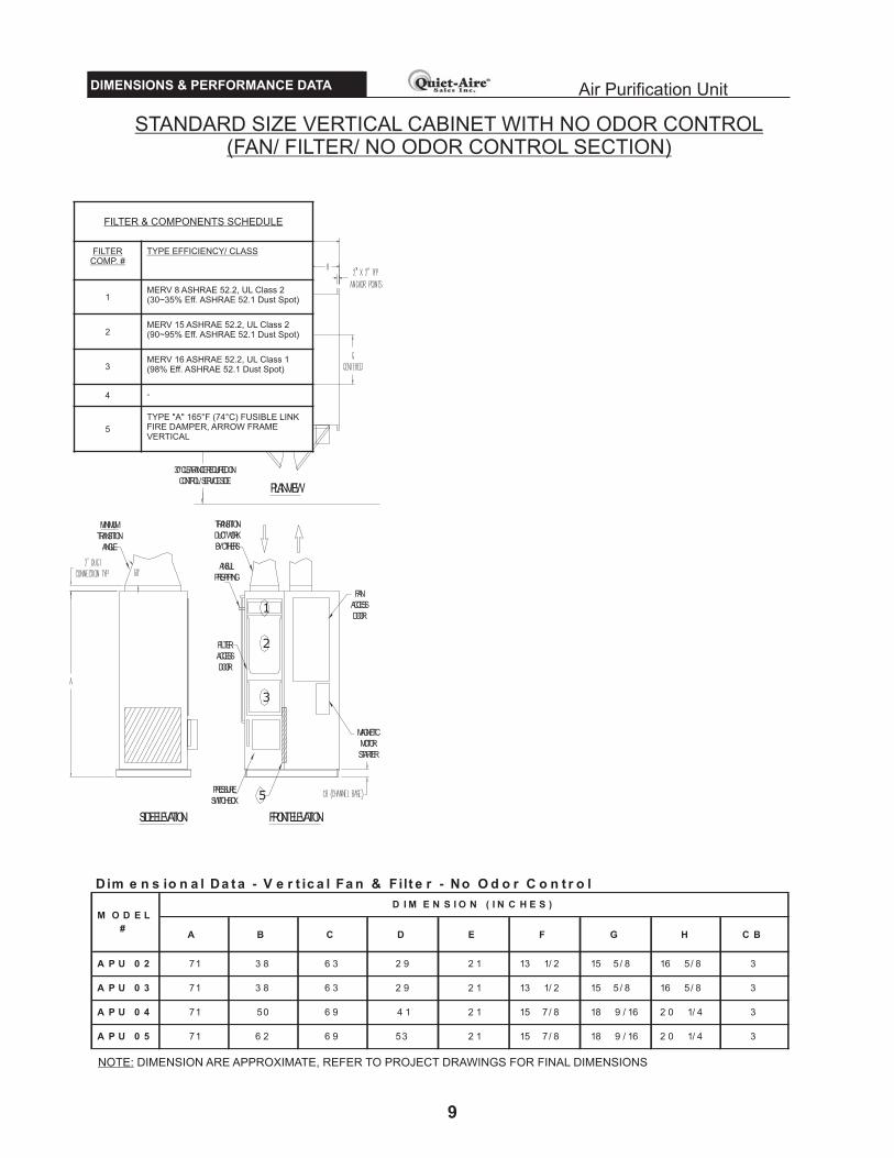
Dim e n s io n a l Da t a - V e r t ic a l Fa n & Filt e r - No O d o r C o n t r o l
A B C D E F G H C B
A P U 0 2 71 3 8 6 3 2 9 2 1 13 1/ 2 15 5/ 8 16 5/ 8 3
A P U 0 3 71 3 8 6 3 2 9 2 1 13 1/ 2 15 5/ 8 16 5/ 8 3
A P U 0 4 71 50 6 9 4 1 2 1 15 7/ 8 18 9 / 16 2 0 1/ 4 3
A P U 0 5 71 6 2 6 9 53 2 1 15 7/ 8 18 9 / 16 2 0 1/ 4 3
M O D E L
#
D I M E N S I O N ( I N C H E S )
STANDARD SIZE VERTICAL CABINET WITH NO ODOR CONTROL(FAN/ FILTER/ NO ODOR CONTROL SECTION)
NOTE: DIMENSION ARE APPROXIMATE, REFER TO PROJECT DRAWINGS FOR FINAL DIMENSIONS
FILTER & COMPONENTS SCHEDULE
FILTERCOMP. #
TYPE EFFICIENCY/ CLASS
1MERV 8 ASHRAE 52.2, UL Class 2(30~35% Eff. ASHRAE 52.1 Dust Spot)
2MERV 15 ASHRAE 52.2, UL Class 2(90~95% Eff. ASHRAE 52.1 Dust Spot)
3MERV 16 ASHRAE 52.2, UL Class 1(98% Eff. ASHRAE 52.1 Dust Spot)
4 -
5
TYPE "A" 165°F (74°C) FUSIBLE LINKFIRE DAMPER, ARROW FRAMEVERTICAL
PRODUCT SPECIFICATIONSDIMENSIONS & PERFORMANCE DATA
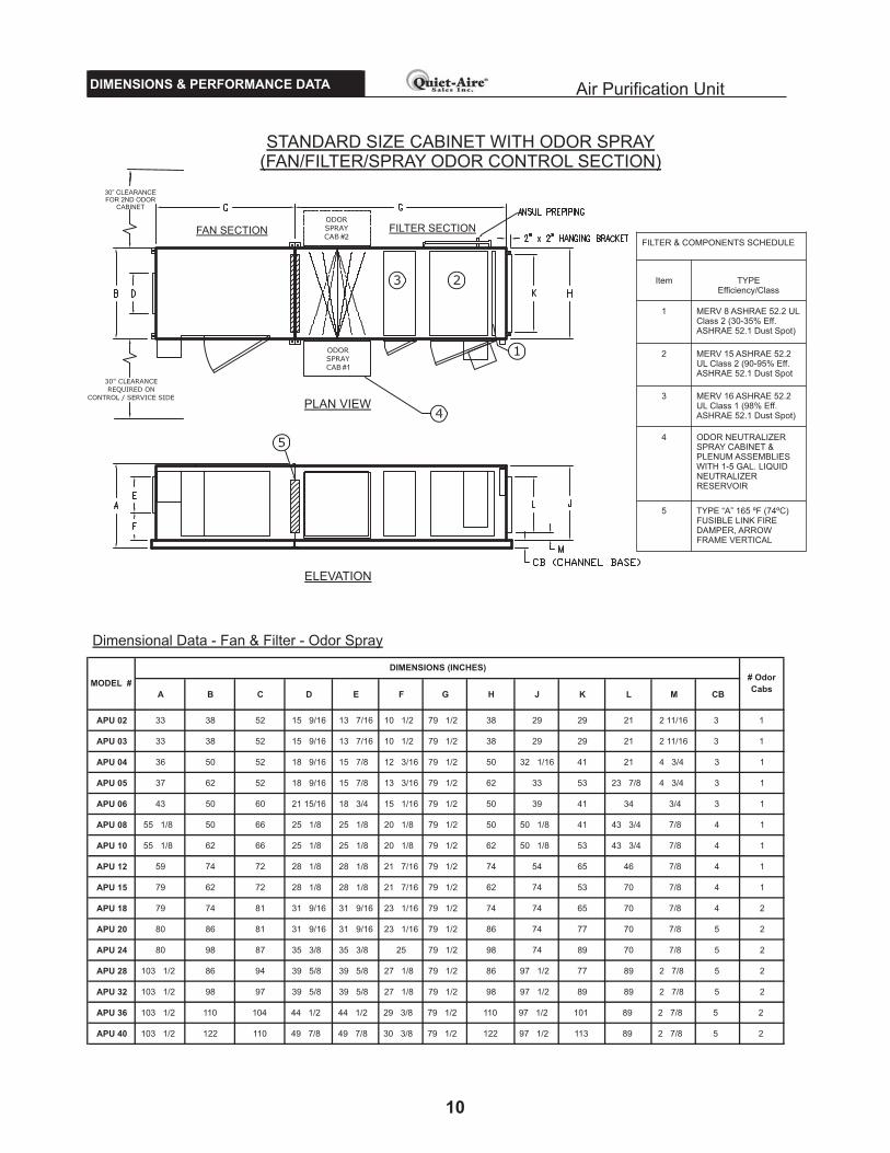
STANDARD SIZE CABINET WITH ODOR SPRAY(FAN/FILTER/SPRAY ODOR CONTROL SECTION)
FAN SECTION FILTER SECTION
PLAN VIEW
ELEVATION
Dimensional Data - Fan & Filter - Odor Spray
Air Purification Unit
10
FILTER & COMPONENTS SCHEDULE
Item TYPEEfficiency/Class
1 MERV 8 ASHRAE 52.2 ULClass 2 (30-35% Eff.ASHRAE 52.1 Dust Spot)
2 MERV 15 ASHRAE 52.2UL Class 2 (90-95% Eff.ASHRAE 52.1 Dust Spot
3 MERV 16 ASHRAE 52.2UL Class 1 (98% Eff.ASHRAE 52.1 Dust Spot)
4 ODOR NEUTRALIZERSPRAY CABINET &PLENUM ASSEMBLIESWITH 1-5 GAL. LIQUIDNEUTRALIZERRESERVOIR
5 TYPE “A” 165 ºF (74ºC)FUSIBLE LINK FIREDAMPER, ARROWFRAME VERTICAL
A B C D E F G H J K L M CB
APU 02 33 38 52 15 9/16 13 7/16 10 1/2 79 1/2 38 29 29 21 2 11/16 3 1
APU 03 33 38 52 15 9/16 13 7/16 10 1/2 79 1/2 38 29 29 21 2 11/16 3 1
APU 04 36 50 52 18 9/16 15 7/8 12 3/16 79 1/2 50 32 1/16 41 21 4 3/4 3 1
APU 05 37 62 52 18 9/16 15 7/8 13 3/16 79 1/2 62 33 53 23 7/8 4 3/4 3 1
APU 06 43 50 60 21 15/16 18 3/4 15 1/16 79 1/2 50 39 41 34 3/4 3 1
APU 08 55 1/8 50 66 25 1/8 25 1/8 20 1/8 79 1/2 50 50 1/8 41 43 3/4 7/8 4 1
APU 10 55 1/8 62 66 25 1/8 25 1/8 20 1/8 79 1/2 62 50 1/8 53 43 3/4 7/8 4 1
APU 12 59 74 72 28 1/8 28 1/8 21 7/16 79 1/2 74 54 65 46 7/8 4 1
APU 15 79 62 72 28 1/8 28 1/8 21 7/16 79 1/2 62 74 53 70 7/8 4 1
APU 18 79 74 81 31 9/16 31 9/16 23 1/16 79 1/2 74 74 65 70 7/8 4 2
APU 20 80 86 81 31 9/16 31 9/16 23 1/16 79 1/2 86 74 77 70 7/8 5 2
APU 24 80 98 87 35 3/8 35 3/8 25 79 1/2 98 74 89 70 7/8 5 2
APU 28 103 1/2 86 94 39 5/8 39 5/8 27 1/8 79 1/2 86 97 1/2 77 89 2 7/8 5 2
APU 32 103 1/2 98 97 39 5/8 39 5/8 27 1/8 79 1/2 98 97 1/2 89 89 2 7/8 5 2
APU 36 103 1/2 110 104 44 1/2 44 1/2 29 3/8 79 1/2 110 97 1/2 101 89 2 7/8 5 2
APU 40 103 1/2 122 110 49 7/8 49 7/8 30 3/8 79 1/2 122 97 1/2 113 89 2 7/8 5 2
MODEL #
DIMENSIONS (INCHES)# Odor
Cabs
#2
#1
30” CLEARANCEFOR 2ND ODOR
CABINET

ODORSPRAY
1
2
3
5 4PRESSURE
SWITCHBOX
MAGNETIC
MOTOR
STARTER
30"CLEARANCEREQUIREDON
CONTROL/SERVICESIDE
ODORSPRAY
FAN
ACCESS
DOOR
TRANSITION
DUCTWORK
BYOTHERS
MINIMUM
TRANSITION
ANGLE
FILTER
ACCESS
DOOR
FRONTELEVATION
PLANVIEW
SIDEELEVATION
ANSUL
PRE-PIPING
PRODUCT SPECIFICATIONSDIMENSIONS & PERFORMANCE DATA Air Purification Unit
11
Dim e n s io n al Data - V e r t ical Fan & Filte r - Od o r Sp r ay
A B C D E F G H C B
A P U 0 2 71 3 8 6 3 2 9 2 1 13 1/ 2 15 5/ 8 16 5/ 8 3
A P U 0 3 71 3 8 6 3 2 9 2 1 13 1/ 2 15 5/ 8 16 5/ 8 3
A P U 0 4 71 50 6 9 4 1 2 1 15 7/ 8 18 9 / 16 2 0 1/ 4 3
A P U 0 5 71 6 2 6 9 53 2 1 15 7/ 8 18 9 / 16 2 0 1/ 4 3
M O D E L
#
D I M E N S I O N ( I N C H E S )
STANDARD SIZE VERTICAL CABINET WITH ODOR SPRAY(FAN/ FILTER/ SPRAY ODOR CONTROL SECTION)
NOTE: DIMENSION ARE APPROXIMATE, REFER TO PROJECT DRAWINGS FOR FINAL DIMENSIONS
FILTER & COMPONENTS SCHEDULE
FILTERCOMP. #
TYPE EFFICIENCY/ CLASS
1MERV 8 ASHRAE 52.2, UL Class 2(30~35% Eff. ASHRAE 52.1 Dust Spot)
2MERV 15 ASHRAE 52.2, UL Class 2(90~95% Eff. ASHRAE 52.1 Dust Spot)
3MERV 16 ASHRAE 52.2, UL Class 1(98% Eff. ASHRAE 52.1 Dust Spot)
4
ODOR NEUTRALIZER SPRAYCABINET & PLENUM ASSEMBLIESWITH 1-5 GAL. LIQUID NEUTRALIZERRESERVOIR
5TYPE "A" 165°F (74°C) FUSIBLE LINKFIRE DAMPER, ARROW FRAMEVERTICAL

PRODUCT SPECIFICATIONSDIMENSIONS & PERFORMANCE DATA
STANDARD SIZE CABINET WITH ODOR MEDIA TRAYS(FAN/FILTER/MEDIA TRAY ODOR CONTROL SECTION)
FAN SECTION FILTER SECTION
PLAN VIEW
ELEVATION
Dimensional Data - Fan & Filter - Media Tray
Air Purification Unit
12
FILTER & COMPONENTS SCHEDULE
Item TYPEEfficiency/Class
1 MERV 8 ASHRAE 52.2 ULClass 2 (30-35% Eff.ASHRAE 52.1 Dust Spot)
2 MERV 15 ASHRAE 52.2UL Class 2 (90-95% Eff.ASHRAE 52.1 Dust Spot
3 MERV 16 ASHRAE 52.2UL Class 1 (98% Eff.ASHRAE 52.1 Dust Spot)
4 ODOR ABSORBINGMEDIA TRAYS
5 TYPE “A” 165 ºF (74ºC)FUSIBLE LINK FIREDAMPER, ARROWFRAME VERTICAL
A B C D E F G H J K L M CB24" x 24" x
2"
24" x 12" x
2"
APU 02 33 38 52 15 9/16 13 7/16 10 1/2 79 1/2 38 29 29 21 2 11/16 3 5 5
APU 03 33 38 52 15 9/16 13 7/16 10 1/2 79 1/2 38 29 29 21 2 11/16 3 5 5
APU 04 36 50 52 18 9/16 15 7/8 12 3/16 79 1/2 50 32 1/16 41 21 4 3/4 3 10 0
APU 05 37 62 52 18 9/16 15 7/8 13 3/16 79 1/2 62 33 53 23 7/8 4 3/4 3 10 5
APU 06 43 50 60 21 15/16 18 3/4 15 1/16 79 1/2 50 39 41 34 3/4 3 10 10
APU 08 55 1/8 50 66 25 1/8 25 1/8 20 1/8 79 1/2 50 50 1/8 41 43 3/4 7/8 4 20 0
APU 10 55 1/8 62 66 25 1/8 25 1/8 20 1/8 79 1/2 62 50 1/8 53 46 7/8 4 20 10
APU 12 59 74 72 28 1/8 28 1/8 21 7/16 79 1/2 74 54 65 46 7/8 4 30 0
APU 15 79 62 72 28 1/8 28 1/8 21 7/16 79 1/2 62 74 53 70 7/8 4 30 15
APU 18 79 74 81 31 9/16 31 9/16 23 1/16 79 1/2 74 74 65 70 7/8 4 45 0
APU 20 80 86 81 31 9/16 31 9/16 23 1/16 79 1/2 86 74 77 70 7/8 5 45 15
APU 24 80 98 87 35 3/8 35 3/8 25 79 1/2 98 74 89 70 7/8 5 60 0
APU 28 103 1/2 86 94 39 5/8 39 5/8 27 1/8 79 1/2 86 97 1/2 77 89 2 7/8 5 60 20
APU 32 103 1/2 98 97 39 5/8 39 5/8 27 1/8 79 1/2 98 97 1/2 89 89 2 7/8 5 80 0
APU 36 103 1/2 110 104 44 1/2 44 1/2 29 3/8 79 1/2 110 97 1/2 101 89 2 7/8 5 80 20
APU 40 103 1/2 122 110 49 7/8 49 7/8 30 3/8 79 1/2 122 97 1/2 113 89 2 7/8 5 100 0
MODEL #
DIMENSION (inches) TRAYS

1
2
3
5PRESSURE
SWITCHBOX
MAGNETIC
MOTOR
STARTER
30"CLEARANCEREQUIREDON
CONTROL/SERVICESIDE
FAN
ACCESS
DOOR
TRANSITION
DUCTWORK
BYOTHERS
MINIMUM
TRANSITION
ANGLE
FILTER
ACCESS
DOOR
FRONTELEVATION
PLANVIEW
SIDEELEVATION
4
ANSUL
PRE-PIPING
PRODUCT SPECIFICATIONSDIMENSIONS & PERFORMANCE DATA Air Purification Unit
13
Dim e n s io n a l Da t a - V e r t ic a l Fa n & Filt e r - O d o r M e d ia T r a y s
A B C D E F G H C B
2 4 " x
2 4 " x
2 "
2 4 " x
12 " x
2 "
A P U 0 2 9 5 3 8 6 3 2 9 2 1 13 1/ 2 15 5/ 8 16 5/ 8 3 5 5
A P U 0 3 9 5 3 8 6 3 2 9 2 1 13 1/ 2 15 5/ 8 16 5/ 8 3 5 5
A P U 0 4 9 5 50 6 9 4 1 2 1 15 7/ 8 18 4 / 7 2 0 1/ 4 3 10 0
A P U 0 5 9 5 6 2 6 9 53 2 1 15 7/ 8 18 4 / 7 2 0 1/ 4 3 10 5
M O D E L
#
D I M E N S I O N ( I N C H E S ) T R A Y S
STANDARD SIZE VERTICAL CABINET ODOR MEDIA TRAYS(FAN/ FILTER/ MEDIA TRAY ODOR CONTROL SECTION)
NOTE: DIMENSION ARE APPROXIMATE, REFER TO PROJECT DRAWINGS FOR FINAL DIMENSIONS
FILTER & COMPONENTS SCHEDULE
FILTERCOMP. #
TYPE EFFICIENCY/ CLASS
1MERV 8 ASHRAE 52.2, UL Class 2(30~35% Eff. ASHRAE 52.1 Dust Spot)
2MERV 15 ASHRAE 52.2, UL Class 2(90~95% Eff. ASHRAE 52.1 Dust Spot)
3MERV 16 ASHRAE 52.2, UL Class 1(98% Eff. ASHRAE 52.1 Dust Spot)
4 ODOR ABSORBING MEDIA TRAYS
5
TYPE "A" 165°F (74°C) FUSIBLE LINKFIRE DAMPER, ARROW FRAMEVERTICAL

AP
U E
co
log
y D
WD
I F
an
Air
Perf
orm
an
ce T
ab
lePRODUCT SPECIFICATIONS Air Purification UnitENGINEERING DATA
14
CFM
L/Se
cR
PM
BH
PK
WR
PM
BH
PK
WR
PM
BH
PK
WR
PM
BH
PK
WR
PM
BH
PK
WR
PM
BH
PK
WR
PM
BH
PK
WR
PM
BH
PK
W
1500
708
2528
1.69
1.26
2672
1.94
1.45
2801
2.19
1.63
2924
2.44
1.82
3042
2.70
2.01
3156
2.97
2.22
3267
3.24
2.42
3368
3.51
2.62
2000
944
2591
2.07
1.54
2728
2.35
1.75
2851
2.62
1.95
2970
2.89
2.16
3084
3.18
2.37
3195
3.47
2.59
3302
3.77
2.81
3401
4.05
3.02
2100
991
2607
2.15
1.60
2743
2.44
1.82
2865
2.71
2.02
2983
2.99
2.23
3096
3.28
2.45
3206
3.58
2.67
3312
3.88
2.89
3410
4.17
3.11
2500
1180
2683
2.53
1.89
2814
2.84
2.12
2931
3.14
2.34
3044
3.44
2.57
3154
3.75
2.80
3260
4.07
3.04
3363
4.39
3.27
3458
4.70
3.51
3000
1416
2799
3.09
2.31
2923
3.44
2.57
3034
3.76
2.80
3142
4.10
3.06
3247
4.44
3.31
3349
4.78
3.57
3448
5.13
3.83
3539
5.47
4.08
3100
1463
2059
3.24
2.42
2162
3.65
2.72
2255
4.05
3.02
2344
4.45
3.32
2430
4.86
3.63
2513
5.27
3.93
2594
5.29
3.95
2668
6.08
4.54
3500
1652
2106
3.64
2.72
2207
4.08
3.04
2297
4.51
3.36
2385
4.94
3.69
2469
5.38
4.01
2550
5.82
4.34
2629
6.27
4.68
2702
6.70
5.00
4000
1888
2170
4.20
3.13
2269
4.68
3.49
2357
5.14
3.83
2442
5.61
4.19
2524
6.08
4.54
2604
6.56
4.89
2681
7.05
5.26
2752
7.51
5.60
4100
1935
1826
4.07
3.04
1924
4.63
3.45
2012
5.16
3.85
2096
5.71
4.26
2176
6.28
4.68
2255
6.86
5.12
2330
7.45
5.56
2400
8.03
5.99
4500
2124
1848
4.41
3.29
1944
4.98
3.72
2030
5.53
4.13
2113
6.10
4.55
2193
6.69
4.99
2270
7.12
5.31
2345
7.90
5.89
2414
8.49
6.33
5000
2360
1878
4.86
3.63
1972
5.46
4.07
2056
6.04
4.51
2138
6.64
4.95
2216
7.24
5.40
2292
7.87
5.87
2366
8.50
6.34
2434
9.11
6.80
5100
2407
1885
4.96
3.70
1978
5.57
4.16
2062
6.15
4.59
2143
6.75
5.04
2221
7.36
5.49
2297
7.99
5.96
2370
8.63
6.44
2438
9.25
6.90
5500
2596
1913
5.37
4.01
2004
6.00
4.48
2087
6.60
4.92
2166
7.22
5.39
2243
7.85
5.86
2318
8.50
6.34
2390
9.16
6.83
2457
9.79
7.30
6000
2832
1952
5.94
4.43
2041
6.59
4.92
2121
7.22
5.39
2198
7.87
5.87
2274
8.52
6.36
2347
9.19
6.86
2418
9.87
7.36
2484
10.5
37.
86
6100
2879
1652
6.03
4.50
1744
6.91
5.15
1826
7.76
5.79
1905
8.64
6.45
1981
9.55
7.12
2054
10.4
77.
8121
2511
.40
8.50
n/a
n/a
n/a
7000
3304
1678
6.66
4.97
1765
7.57
5.65
1844
8.46
6.31
1921
9.37
6.99
1995
10.3
17.
6920
6711
.28
8.41
2137
12.2
79.
1522
0213
.23
9.87
8000
3776
1719
7.52
5.61
1801
8.45
6.30
1875
9.36
6.98
1948
10.3
07.
6820
1911
.27
8.41
2089
12.2
79.
1521
5613
.30
9.92
2219
14.2
910
.66
8100
3823
1723
7.61
5.68
1805
8.55
6.38
1879
9.46
7.06
1952
10.4
07.
7620
2211
.38
8.49
2091
12.3
89.
2421
5913
.41
10.0
022
2114
.41
10.7
5
9000
4248
1771
8.55
6.38
1847
9.51
7.09
1918
10.4
47.
7919
8611
.40
8.50
2054
12.4
09.
2521
2013
.42
10.0
121
8514
.48
10.8
022
4515
.49
11.5
6
1000
047
1918
349.
787.
3019
0510
.77
8.03
1971
11.7
38.
7520
3512
.72
9.49
2098
13.7
310
.24
2161
14.7
811
.03
2223
15.8
511
.82
2280
16.8
912
.60
1010
047
6715
319.
397.
0016
0210
.55
7.87
1668
11.6
98.
7217
3212
.88
9.61
1797
14.1
210
.53
1860
15.3
911
.48
1922
16.7
012
.46
1980
17.9
713
.41
1100
051
9115
6710
.31
7.69
1634
11.4
88.
5616
9512
.62
9.41
1756
13.8
210
.31
1816
15.0
611
.23
1876
16.3
512
.20
1935
17.6
713
.18
1990
18.9
714
.15
1200
056
6316
1511
.50
8.58
1677
12.6
99.
4717
3413
.84
10.3
217
9115
.04
11.2
218
4716
.29
12.1
519
0317
.58
13.1
119
5918
.91
14.1
120
1120
.21
15.0
8
1210
057
1116
2011
.63
8.68
1681
12.8
29.
5617
3913
.98
10.4
317
9515
.18
11.3
218
5116
.42
12.2
519
0617
.71
13.2
119
6119
.05
14.2
120
1320
.35
15.1
8
1400
066
0717
2414
.37
10.7
217
8015
.63
11.6
618
3116
.85
12.5
718
8118
.09
13.5
019
3119
.37
14.4
519
8120
.68
15.4
320
3022
.03
16.4
320
7623
.33
17.4
0
1500
070
7917
8416
.05
11.9
718
3717
.37
12.9
618
8618
.62
13.8
919
3419
.90
14.8
519
8121
.21
15.8
220
2822
.54
16.8
120
7423
.90
17.8
321
1825
.22
18.8
1
10, 1
5, 2
0, 2
5
15, 2
0, 2
5, 3
0
5, 7
.5, 1
0
5, 7
.5, 1
0
7.5,
10,
15
7.5,
10,
15,
20
10, 1
5, 2
0
5.0"
W.C
./1.2
4 kP
a
Odo
rTr
ay=>
Mot
or
HP
3, 5
3, 5
, 7.5
4.0"
W.C
./0.9
93 k
Pa
4.5"
W.C
./1.1
2 kP
a
10 150802 03 04 05 06
2.0"
W.C
./0.4
96 k
Pa
2.5"
W.C
./0.6
20 k
Pa
3.0"
W.C
./0.7
45 k
Pa
3.5"
W.C
./0.8
69 k
Pa
12
No
Odo
rTr
ay=>
APU
Mod
el
No.
1.5"
W.C
./0.3
72 k
Pa
EX
TE
RN
AL
STA
TIC
PR
ES
SU
RE
1.0
"W
.C./
0.24
8kP
a1.
5" W
.C./0
.372
kP
a2.
0" W
.C./0
.496
kP
a2.
5" W
.C./0
.620
kP
a3.
0" W
.C./0
.745
kP
a3.
5" W
.C./0
.869
kP
a4.
0" W
.C./0
.993
kP
a4.
5" W
.C./1
.12
kPa

PRODUCT SPECIFICATIONS Air Purification UnitENGINEERING DATA
AP
U E
co
log
y D
WD
I F
an
Air
Perf
orm
an
ce T
ab
le
15
No
tes:
(1)
AP
Usiz
es s
ho
wn
are
the
sta
nd
ard
blo
we
r/ca
bin
et
co
mb
ina
tio
ns,
Qu
iet-
Aire
Sa
les I
nc.
rese
rve
s t
he
rig
ht
toch
an
ge
tho
se
co
mb
ina
tio
ns t
oa
cco
mo
da
tejo
bsp
ecific
atio
ns
(2)
For
sta
tic p
ressure
s n
ot show
nple
ase
conta
ct Q
uie
t-A
ire
(3)
Bre
ak h
ors
ep
ow
er
(BH
P)
inclu
de
s d
rive
losse
s
CFM
L/Se
cR
PM
BH
PK
WR
PM
BH
PK
WR
PM
BH
PK
WR
PM
BH
PK
WR
PM
BH
PK
WR
PM
BH
PK
WR
PM
BH
PK
WR
PM
BH
PK
W
15100
7126
1425
14.1
610.5
61482
15.6
711
.69
1534
17.1
412.7
91586
18.6
713.9
31637
20.2
615.1
11688
21.9
116.3
41739
22.6
316.8
81
78
62
5.3
118.8
8
16000
7551
1456
15.3
011
.41
1510
16.8
312.5
61560
18.3
113.6
61610
19.8
614.8
21659
21.4
516.0
01708
23.1
117.2
41756
24.8
218.5
21
80
22
6.4
919.7
6
18000
8495
1531
18.1
913.5
71582
19.8
114.7
81627
21.3
515.9
31673
22.9
417.1
11718
24.5
718.3
31762
26.2
519.5
81806
27.9
720.8
71
84
82
9.6
422.1
1
18100
8542
1535
18.3
413.6
81585
19.9
714.9
01631
21.5
216.0
51676
23.1
117.2
41721
24.7
418.4
61765
26.4
219.7
11809
28.1
420.9
91
85
02
9.8
222.2
5
19000
8967
1572
19.8
114.7
81620
21.4
816.0
21665
23.0
817.2
21708
24.7
018.4
31751
26.3
619.6
61794
28.0
620.9
31836
29.8
022.2
31
97
63
1.4
823.4
8
20000
9439
1614
21.5
616.0
81661
23.2
917.3
71703
24.9
418.6
11745
26.6
119.8
51787
28.3
021.1
11828
30.0
422.4
11869
31.8
023.7
21
90
73
3.5
024.9
9
20100
9486
1285
18.7
914.0
21335
20.7
515.4
81381
22.6
416.8
91426
24.5
718.3
31470
26.5
519.8
11513
28.5
921.3
31556
30.6
722.8
81
59
63
2.6
924.3
9
21400
10100
1317
20.4
515.2
61365
22.4
716.7
61409
24.4
118.2
11452
26.4
019.6
91494
28.4
321.2
11536
30.5
122.7
61577
32.6
424.3
51
61
63
4.6
925.8
8
21500
10147
1320
20.5
815.3
51367
22.6
116.8
71411
24.5
518.3
11454
26.5
519.8
11494
28.4
321.2
11538
30.6
722.8
81579
32.8
024.4
71
61
73
4.8
526.0
0
24000
11327
1384
24.2
118.0
61430
26.3
619.6
61471
28.4
221.2
01511
30.5
222.7
71550
32.6
624.3
61589
34.8
425.9
91627
37.0
627.6
51
66
33
9.2
029.2
4
24100
11374
1128
22.0
916.4
811
72
24.4
318.2
21213
26.6
919.9
11253
29.0
321.6
61293
31.4
423.4
51333
33.9
525.3
31372
36.5
227.2
41
40
83
9.0
329.1
2
26300
12412
1167
24.8
718.5
51209
27.3
020.3
71247
29.6
222.1
01285
32.0
223.8
91322
34.4
925.7
31359
37.0
227.6
21396
39.6
329.5
61
43
04
2.1
731.4
6
26400
12459
1169
25.0
118.6
61210
27.4
320.4
61248
29.7
722.2
11286
32.1
623.9
91323
34.6
325.8
31360
37.1
727.7
31397
39.7
829.6
81
43
14
2.3
331.5
8
28000
13215
1200
27.2
620.3
41240
29.7
622.2
01276
32.1
523.9
81312
34.6
125.8
21348
37.1
327.7
01383
39.7
029.6
21418
42.3
531.5
91
45
14
4.9
233.5
1
28100
13262
1202
27.4
020.4
41242
29.9
122.3
11278
32.3
124.1
01314
34.7
725.9
41349
37.2
927.8
21385
39.8
729.7
41419
42.5
231.7
21
45
24
5.0
933.6
4
30000
14158
1241
30.3
322.6
31278
32.9
424.5
71313
35.4
326.4
31347
37.9
728.3
31381
40.5
530.2
51415
43.1
932.2
21448
45.9
034.2
41
47
94
8.5
136.1
9
32000
15102
1283
33.7
025.1
41319
36.4
227.1
71352
39.0
129.1
01385
41.6
531.0
71418
44.3
233.0
61450
47.0
535.1
01481
49.8
337.1
71
51
15
2.4
939.1
6
32100
15150
1010
29.9
722.3
61047
32.9
624.5
91082
35.8
426.7
411
16
38.7
928.9
411
50
41.8
131.1
911
83
44.9
033.5
01215
48.0
635.8
51
24
65
1.1
238.1
4
32700
15433
1018
30.7
522.9
41055
33.7
725.1
91089
36.6
727.3
611
22
39.6
429.5
711
55
42.6
831.8
411
88
45.8
034.1
71220
48.9
836.5
41
25
05
2.0
638.8
4
32800
15480
1019
30.8
823.0
41056
33.9
125.3
01090
36.8
127.4
611
23
39.7
929.6
811
56
42.8
331.9
511
89
45.9
534.2
81221
49.1
336.6
51
25
15
2.2
238.9
6
36000
16990
1062
35.4
226.4
21096
38.5
928.7
911
28
41.6
431.0
611
59
44.7
533.3
811
90
47.9
235.7
51221
51.1
638.1
71251
54.4
740.6
31
27
95
7.6
543.0
1
36100
17037
881
32.1
924.0
1917
35.7
126.6
4952
39.1
429.2
0986
42.7
331.8
81019
46.4
934.6
81053
50.4
037.6
01086
54.4
540.6
21
11
75
8.4
443.6
0
39700
18736
911
36.4
927.2
2945
40.1
229.9
3976
43.5
932.5
21008
47.2
235.2
31039
50.9
938.0
41070
54.8
740.9
311
01
58.9
143.9
51
13
06
2.8
646.8
9
39800
18784
912
36.6
327.3
3946
40.2
430.0
2977
43.7
432.6
31008
47.3
535.3
21040
51.1
238.1
41070
55.0
041.0
311
01
59.0
544.0
51
13
06
3.0
047.0
0
40000
18878
914
36.9
027.5
3948
40.5
130.2
2979
44.0
032.8
21010
47.6
435.5
41041
51.3
938.3
41072
55.2
941.2
511
02
59.3
244.2
51
13
16
3.2
747.2
0
20
, 25
,
30
, 40
, 50
25
, 30
,
40
, 50
30
, 40
,
50
, 60
30
, 40
,
50
, 60
, 75
40
, 50
,
60
, 75
Mo
tor
HP
15
, 20
,
25
, 30
,
40
20
, 25
,
30
, 40
18 40
20 32
24 28
1.5
" W
.C./0.3
72 k
Pa
36
3.0
" W
.C./0.7
45 k
Pa
3.5
" W
.C./0.8
69 k
Pa
4.0
" W
.C./0.9
93 k
Pa
4.5
" W
.C./1.1
2 k
Pa
2.0
" W
.C./0.4
96 k
Pa
2.5
" W
.C./0.6
20 k
Pa
3.0
" W
.C./0.7
45 k
Pa
3.5
" W
.C./0.8
69 k
Pa
4.0
" W
.C./0.9
93 k
Pa
Od
or
Tray
=>1.
0"
W.C
./0.
248
kPa
1.5
" W
.C./0.3
72 k
Pa
2.0
" W
.C./0.4
96 k
Pa
2.5
" W
.C./0.6
20 k
Pa
EX
TE
RN
AL
STA
TIC
PR
ES
SU
RE
4.5
" W
.C./1.1
2 k
Pa
5.0
" W
.C./1.2
4 k
Pa
AP
U
Mo
del
No
.
No
Od
or
Tray
=>

16
APU ATTRIBUTES & FILTER SCHEDULE
APU ATTRIBUTE CHARTUNIT MOTOR FILTER OS FILTER/ODOR OT FILTER/ODOR FAN
(hp) SECTION (lbs.) SECTION (lbs.) SECTION (lbs.) SECTION (lbs.)
APU 02 3, 5 385 495 660 760
APU 03 3, 5, 7.5 490 600 915 765
APU 04 5, 7.5, 10 505 705 1,060 935
APU 05 5, 7.5,10 590 805 1,270 1,215
APU 06 7.5, 10, 15 610 905 1,475 1,090
APU 08 7.5, 10, 20 730 970 1,740 1,265
APU 10 10, 15, 20 850 1,100 2,080 1,490
APU 12 10, 15, 20, 25 950 1,235 2,415 1,785
APU 15 15, 20, 25, 30 1,080 1,420 2,925 1,960
APU 18 15, 20, 25, 30, 40 1,185 1,632 3,355 2,105
APU 20 20, 25, 30, 40 1,375 1,787 3,815 2,460
APU 24 20, 25, 30, 40, 50 1,520 2,050 4,334 2,895
APU 28 25, 30, 40, 50 1,710 2,317 4,830 3,680
APU 32 30, 40, 50, 60 1,860 2,482 5,485 3,775
APU 36 30, 40, 50, 60, 75 2,075 2,682 6,100 4,795
APU 40 40, 50, 60, 75 2,405 2,861 6,680 5,245
FILTER SCHEDULEUNIT PLEATED PRE FILTER BAG FILTER BOX FILTER
24" x 12" x 4" 24" x 24" x 4" 24" x 12" x 22" 24" x 24" x 22" 24" x 12" x 12" 24" x 24" x 12"
APU 02 0 1 0 1 0 1
APU 03 1 1 1 1 1 1
APU 04 0 2 0 2 0 2
APU 05 1 2 1 2 1 2
APU 06 2 2 2 2 2 2
APU 08 0 4 0 4 0 4
APU 10 2 4 2 4 2 4
APU 12 0 6 0 6 0 6
APU 15 3 6 3 6 3 6
APU 18 0 9 0 9 0 9
APU 20 3 9 3 9 3 9
APU 24 0 12 0 12 0 12
APU 28 4 12 4 12 4 12
APU 32 0 16 0 16 0 16
APU 36 4 16 4 16 4 16
APU 40 0 20 0 20 0 20
Air Purification Unit

APU ATTRIBUTES & FILTER SCHEDULE Air Purification Unit
17
LENGTH WIDTH * HEIGHT
(INCHES) (INCHES) (INCHES)
Filter Section 57 53 35
OS Filter / Odor Section 86 59 35
OT Filter / Odor Section 86 53 35
Fan Section 58 54 35
Vertical Unit No Odor Control 71 51 75
Vertical Unit With Odor Spray 71 57 75
Vertical Unit With Odor Media Trays 71 51 75
Filter Section 57 53 35
OS Filter / Odor Section 86 59 35
OT Filter / Odor Section 86 53 35
Fan Section 58 54 35
Vertical Unit No Odor Control 71 51 75
Vertical Unit With Odor Spray 71 57 75
Vertical Unit With Odor Media Trays 71 51 75
Filter Section 57 65 38
OS Filter / Odor Section 86 71 38
OT Filter / Odor Section 86 65 38
Fan Section 58 66 38
Vertical Unit No Odor Control 77 63 75
Vertical Unit With Odor Spray 77 70 75
Vertical Unit With Odor Media Trays 77 63 75
Filter Section 57 77 39
OS Filter / Odor Section 86 83 39
OT Filter / Odor Section 86 77 39
Fan Section 58 78 39
Vertical Unit No Odor Control 77 75 75
Vertical Unit With Odor Spray 77 81 75
Vertical Unit With Odor Media Trays 77 75 75
Filter Section 57 65 45
OS Filter / Odor Section 86 71 45
OT Filter / Odor Section 86 65 45
Fan Section 66 66 45
Filter Section 57 65 57
OS Filter / Odor Section 86 71 57
OT Filter / Odor Section 86 65 57
Fan Section 72 66 57
Filter Section 57 77 57
OS Filter / Odor Section 86 83 57
OT Filter / Odor Section 86 77 57
Fan Section 72 78 57
* Includes 4" Allowance for Ansul pre-piping
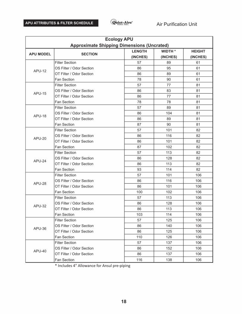
Approximate Shipping Dimensions (Uncrated)
Ecology APU
APU MODEL SECTION
APU-10
APU-02
APU-03
APU-04
APU-05
APU-06
APU-08
Air Purification UnitAPU ATTRIBUTES & FILTER SCHEDULE
18
LENGTH WIDTH * HEIGHT
(INCHES) (INCHES) (INCHES)
Filter Section 57 89 61
OS Filter / Odor Section 86 95 61
OT Filter / Odor Section 86 89 61
Fan Section 78 90 61
Filter Section 57 77 81
OS Filter / Odor Section 86 83 81
OT Filter / Odor Section 86 77 81
Fan Section 78 78 81
Filter Section 57 89 81
OS Filter / Odor Section 86 104 81
OT Filter / Odor Section 86 89 81
Fan Section 87 90 81
Filter Section 57 101 82
OS Filter / Odor Section 86 116 82
OT Filter / Odor Section 86 101 82
Fan Section 87 102 82
Filter Section 57 113 82
OS Filter / Odor Section 86 128 82
OT Filter / Odor Section 86 113 82
Fan Section 93 114 82
Filter Section 57 101 106
OS Filter / Odor Section 86 116 106
OT Filter / Odor Section 86 101 106
Fan Section 100 102 106
Filter Section 57 113 106
OS Filter / Odor Section 86 128 106
OT Filter / Odor Section 86 113 106
Fan Section 103 114 106
Filter Section 57 125 106
OS Filter / Odor Section 86 140 106
OT Filter / Odor Section 86 125 106
Fan Section 110 126 106
Filter Section 57 137 106
OS Filter / Odor Section 86 152 106
OT Filter / Odor Section 86 137 106
Fan Section 116 138 106
* Includes 4" Allowance for Ansul pre-piping
SECTION
Approximate Shipping Dimensions (Uncrated)
Ecology APU
APU-12
APU-32
APU-36
APU-40
APU-15
APU-18
APU-20
APU-24
APU-28
APU MODEL

WIRING DIAGRAMS Air Purification Unit
AC
D
19

WIRING DIAGRAMS Air Purification Unit
AC
W
20

WIRING DIAGRAMS Air Purification Unit
B
B
AC
W -
HO
A
AC
W -
HO
A
21

PRODUCT SPECIFICATIONS Air Purification UnitGENERAL DESCRIPTION
FILTER SECTION
Provide a Quiet-Aire® Ecology Air Purification Unit (APU), Model # APU -
____ – ____–____ –____–____–____–____–____ , assembled, wired
and fully factory-tested prior to shipment. Unit shall be complete,
including a filter section, air monitor cabinet, status panel, and all other
options and components as specified below and as shown on the
drawings. TheAPU shall have a capacity of ____________ CFM.
The complete APU assembly provided shall be ETL or ETL C listed, and
the construction shall meet the requirements of national building codes,
the local authority having jurisdiction, and NFPA96.
The APU shall be used in conjunction with a listed water-wash or dry
grease extracting exhaust ventilator (hood) having a minimum grease
extraction rate of 90% by weight.
The filter section, ETL or ETL C listed, housing shall be of double-wall
construction with welded channel bracing for maximum rigidity and
strength. A minimum of 1 1/2” fire proof mineral insulation will be fixed
between inner and outer wall, roof and floor sheet steel. The inner
housing walls shall be of 16-gauge steel, with all seams fully-welded
liquid-tight. The outer housing walls shall be of 20-gauge steel, painted
after fabrication. The housing is to include a supporting base comprised
of full-length 3” minimum structural longitudinal and cross-bracing
channel members. Refer to project drawings for actual channel member
sizing. The base shall be configured so the filter section can be
suspended from above, if required (horizontal units only). The filter
section shall further comprise:
A. For particulate grease and smoke abatement, a three stage filtration
system, with a nominal 500 FPM filter face velocity, and comprising three-
stages of filtration:
1. A first stage pre-filter is a 4” deep pleated type and is an ASHRAE
standard rated MERV 8 (30-35% Eff.), ULClass 2
2. A second stage bag-filter is a 22” deep bag type and is an
ASHRAE standard rated MERV 15 (90-95% Eff.), ULClass 2
3. A third stage box-filter is a 12” deep, fire rated, absolute filter and
is anASHRAE standard rated MERV 16 (98% Eff.), ULClass 1
B. Hinged access doors with toggle-type latches provide for complete
access to the filters. Doors and panels shall be double-wall construction
with the outer wall of 16 gauge steel and the inner wall of 16 gauge steel
and further include ETL/ETL C fire rated gaskets to form a grease tight
seal when closed.
C. A UL/ULC listed fire damper at the discharge end. The damper shall
be actuated by a 165°F fusible link.
D. A firestat, located within the filter section, when activated at 200°F, will
shut off the exhaust fan and transmit a fire alarm signal to the remote
status panel.
E. A monitoring system, measuring the differential pressure across each
filter stage, and monitoring a final filter out condition. Pressure switches
wired to send signals to the remotely located status panel, shall be
housed within a unit-mounted, air monitor cabinet on the filter section.
F. Optionally supply “ANSUL” brand fire suppression pre-piping and
suppression nozzles facing the lead face of the first filter bank and the
trailing face of the final filter bank. Piping and nozzles to be factory
installed by certified technicians. Chemical supply system and
activation devices are to be supplied by others.
If odor abatement is to be included, the filter section housing shall be
extended to incorporate an odor control module consisting of:
Odor Neutralization: Provide one or two unit-mounted odor
spray cabinet(s) housing a 5 gallon tank, a liquid spray
compressor, one nozzle, and fuse-protected circuitry with
spray and delay period adjustable timers.
Optionally, equip the odor spray cabinet(s) with the HS
heater option for use in environments that fall below 32˚F.
Potassium Permanganate andActivated Carbon: Provide a
V-bank array of 2” deep perforated trays containing a
50%-50% blend of activated alumina spheres impregnated
with potassium permanganate for oxidizing odor molecules,
and activated carbon for absorption/adsorption of the
odor molecules in the passing airstream. The trays are to
include removable front panels to facilitate the changing of
the media spheres.
ODOR CONTROL
PLEASE CHOOSE ONE OF THE TWO SELECTIONS LISTED
BETWEEN THE LINES BELOW
OR
22

PRODUCT SPECIFICATIONS Air Purification UnitBLOWER SECTION
Blower to have a capacity of _________ CFM at _______inches W.C.
external static pressure. This section, ETL or ETL C listed, to include a
complete airfoil backward curved fan wheel and scroll assembly, Class
T2 construction, connected to a TEFC inverter rated motor by a V-belt
drive, and a combination magnetic motor starter and disconnect panel.
The motor starter panel is surface mounted on the section housing, wired
and factory-tested prior to shipment.
The starter and disconnect panel shall be:
TYPE 1 for indoor installation
TYPE 3R for outdoor installation
The fan and drive assembly shall be supplied with spring type vibration
isolators. Fan motor to be _________HP, _________Volts, ____Phase,
_____Hz.
The centrifugal blower scroll and inlet bell shall be constructed of heavy
gauge steel. The blower shall be DWDI, and the fan wheel shall include
airfoil, backward inclined, curved, non-overloading type blades. The
blower shall be licensed to bear the AMCA Certification Seal. The fan
shaft will be hardened steel, accurately turned and polished. Fan
bearings shall be anti-friction ball pillow block type, with grease fittings for
periodic lubricating.
The V-belt drive and motor shall be on a common chassis base with the
blower, shall include oil resistant, non-static belts, and have capacity of
approximately 25% more than the motor brake horsepower.
This section is mated to the filter section, forming a single
integral packaged unit. See project drawings for section and
air discharge arrangements.
This section is to be remote mounted from the filter section.
See project drawings for section and air discharge
arrangements.
PLEASE CHOOSE ONE OF THE THREE SELECTIONS LISTED
BETWEEN THE LINES BELOW
OR
PLEASE CHOOSE ONE OF THE THREE SELECTIONS LISTED
BETWEEN THE LINES BELOW
OR
OR
OR
Supply a variable frequency drive unit to allow fan
speed control required for energy efficient kitchen operation.
A line reactor is supplied to protect the VFD circuitry. The VFD
and line reactor is to be mounted in a NEMA 1 (indoor) or
NEMA 4 (outdoor) enclosure and attached to the blower
casing. The 0 to 10V control signal is provided by others.
This section is integral to the filter section. Vertical oriented
upright units are designed for indoor & floor mounting only.
The roof, outside walls and floor shall be of 16-gauge steel. The roof liner,
inner housing walls and floor liner shall be of 20-gauge sheet steel. A
minimum of 2” fire proof mineral insulation will be fixed between inner and
outer wall, roof and roof liner, and floor and floor liner sheet steel. The entire
section is to be primed and painted after fabrication. The section housing to
include a base similar to that provided with the filter section, also configured
so the section can be suspended from above (horizontal units only).
, Nil Airflow
, Nil Airflow
STATUS PANEL
Provide a NEMA 4X status panel, ETL or ETL C listed, for remote mounting,
with a housing constructed of grade 304 stainless steel, water-tight access
door with security fasteners. The cabinet is to include a fuse-protected
circuitry including a step-down transformer with a 24-volt secondary
winding, unit prove out timer, relays, and status pilot light indicators in the
face of the panel to continually monitor the status of theAPU.
OPTIONALLY: A fan stop delay timer is supplied on all units as standard
equipment. It is meant for UV hood applications where the byproducts from
UV cleaning should be exhausted for 10 minutes after UV source lights are
turned off.
The status panel shall be an model which is meant for kitchen staff
operation and monitoring. Individual indicators shall be designated for Fan
On/Off Push Button, Power On, Filter Out, Fire, Replace Pre-Filter, Replace
Bag-Filter, Replace Box-Filter, Alarm Buzzer, Nil Airflow, Buzzer Mute Push
Button, Low Odor Liquid (optional); Avoltage free dry contact closing on any
alarm condition providing for remote monitoring of the system
The status panel shall be an model which is meant for hood equipment
control by a water wash or UV control panel and visual status monitoring by
kitchen staff. Individual indicators shall be designated for Fan On, Power
On, Filter Out, Fire, Replace Pre-Filter, Replace Bag-Filter, Replace Box-
Filter , Alarm Buzzer, Buzzer Mute Push Button, Low Odor Liquid
(optional);One 110V control relay is provided for fan start and stop signal
from the hood equipment controller. A voltage free dry contact closing on
any alarm condition providing for remote monitoring of the system
The status panel shall be an model which is meant for a building
management system (BMS) control and monitoring, or maintenance staff
operation and monitoring. Individual indicators shall be designated for Fan
On, Power On, Filter Out, Fire, Replace Pre-Filter, Replace Bag-Filter,
Replace Box-Filter , Alarm Buzzer, Buzzer Mute Push Button,
Low Odor Liquid (optional); HAND-OFF-AUTO key switch mounted on face
of cabinet allows for remote control and monitoring by the BMS when in
AUTO; Relays to provide all APU status signals to the BMS including Fan
On, Filter Out, Fire, Replace Pre-Filter, Replace Bag-Filter, Replace Box-
Filter, Low Odor Liquid(optional). A voltage free dry contact for air make up
is also provided
PLEASE CHOOSE ONE OF THE THREE SELECTIONS LISTED
BETWEEN THE LINES BELOW
ACD
OR
ACW
OR
ACW-HOA
23

Among many others, the Ecology APU is installed in:Air Canada Centre, Toronto, CanadaUniversity of Toronto, Toronto, CanadaMarlboro County Club, Marlboro, New JerseySe De La Terre Restaurant Boston, MassachusettsQueens Quay, Toronto, CanadaEmirates Towers, Dubai, United Arab Emirates
Representedby:
Working in hundreds oflocations around the world;
efficiently, smoothly, and withan eye on the air we breath
Quiet-Aire Sales Inc.7212 Line 86, Box 4Wallenstein Ontario, Canada N0B 2S0P (519) 669-0238www.q-asales.com [email protected]