qas 30 kd - kolex...atlas copco - portable air division printed matter n 2955 1530 00 04/2008 parts...
TRANSCRIPT
QAS 30 Kd Engine V3300DI
Parts List for Portable GeneratorsEnglish


AT
Parts Index................................................................................................5
Warranty and Liability ............................................................................7
Safety Precautions for Portable Generators ..........................................9
Ordering Spare Parts .............................................................................13
Parts Lists ...............................................................................................18
QAS 30 Kd Engine V3300DI
Printed Matter N°
2955 1530 00
04/2008
LAS COPCO - PORTABLE AIR DIVISION
www.atlascopco.com


70, 7136, 3745, 53
......3040, 4140, 41......53
......7433, 6636, 37......7454, 5633, 6636, 37......24......24......2220, 2128, 6728, 6754, 5562, 63
39, 7639, 7625, 6939, 7630, 4854, 56......3252, 7669, 7672, 7372, 73
GGROMMET .................................................................................. 52, 64, 65GUARD .................................................................................................... 26
HHANDGRIP ........................................................................................ 72, 73HANDLE ...................................................................................... 40, 41, 53HEXAGON PLUG ................................................................. 38, 39, 60, 76HINGE .................................................................. 40, 41, 42, 43, 45, 51, 53HOSE ...................................................................................... 23, 26, 32, 59HOSE ASSEMBLY .................................................................................. 38HOSE CLAMP ................................................................. 23, 26, 32, 56, 59HOSE CLIP................................................................................... 32, 38, 54HOUSE MARK ...................................................................... 34, 42, 50, 51HOUSING........................................................................................... 36, 37
IINDICATOR ............................................................................................. 23INFORMATION LABEL ......................................................................... 54INSULATION MONITORING RELAY .................................................. 75
LLABEL...................................................................................................... 34LABEL NOISE ......................................................................................... 34LABEL WEBSITE ................................................................................... 50
MMALE CONTACT.............................................................................. 72, 73MALE INSERT................................................................................... 72, 73MARKINGS ....................................................................................... 34, 35MUFFLER .......................................................................................... 28, 67
OOIL SYSTEM ........................................................................................... 38
PPANEL ...................................................................................................... 50PANELLIGHT .......................................................................................... 72PARCOOL EG .......................................................................................... 22PAROIL............................................................................................... 20, 21
AGE PART PAGE
P
AADAIAIAIALALAMAN
BBABABABABABEBOBUBU
CCACACACICLCOCOCOCOCOCOCOCOCOCOCOCOCOCOCO
P
- 5 -
ARTS INDEX
APTOR.................................................................................................52R FILTER ..............................................................................................23R FILTER ELEMENT ..........................................................................23R INLET................................................................................................23TERNATOR .........................................................................................29TERNATOR AND ACCESSORIES ....................................................29PEREMETER .....................................................................................72TENNA..........................................................................................64, 65
FFLE ....................................................................................................44FFLE ASSEMBLY ........................................................................30, 44TTERY CABLE .............................................................................33, 66TTERY CHARGER .............................................................................58TTERY SWITCH .................................................................................66AM............................................................................................30, 46, 47DYWORK......................................................................................30, 31LB ........................................................................................................72SHING ...........................................................................................26, 56
BLE STRIP ....................................................................................64, 65BLE TIE...............................................................................................26P .....................................................................................................30, 52
RCUIT BREAKER .......................................................36, 37, 71, 72, 73AMP ...................................................................................33, 39, 66, 76NTROL PANEL QC1002 ....................................................................72NTROL PANEL QC2002 ....................................................................73NTROLLER...................................................................................72, 73NVERTOR .....................................................................................64, 65OLANT HEATER................................................................................59OLER ...................................................................................................26OLING SYSTEM ..........................................................................26, 27RNER.................................................................................42, 43, 45, 51RNER ASSEMBLY .....................................................30, 42, 43, 45, 51SMOS.............................................................................................64, 65SMOS MODULE...........................................................................64, 65SMOS WIRING.............................................................................64, 65VER................................................................................................32, 48VER EXHAUST............................................................................28, 67WL FAN...............................................................................................26
CUBICLE................................................................................36, 37, CUBICLE AND ACCESSORIES ......................................................CUBICLE DOOR ASSEMBLY .........................................................
DDOCUMENT HOLDER .....................................................................DOOR..................................................................................................DOOR ASSEMBLY......................................................................30, DOOR CUBICLE ...............................................................................
EEARTH LEAKAGE RELAY ..............................................................EARTH PIN ........................................................................................EARTH RAIL ASSEMBLY................................................................EARTH RELAY..................................................................................ELBOW...............................................................................................ELECTRICAL SYSTEM....................................................................EMERGENCY STOP .........................................................................ENGINE ..............................................................................................ENGINE AND ACCESSORIES.........................................................ENGINE COOLANT..........................................................................ENGINE OIL ......................................................................................EXHAUST ..........................................................................................EXHAUST SYSTEM .........................................................................EXTERNAL FUEL TANK CONNECTION ......................................EYE .....................................................................................................
FFLANGE .............................................................................................FRAME ...............................................................................................FRAME AND MOUNTS....................................................................FRAME ASSEMBLY ...................................................................25, FRONT ROOF ASSEMBLY..............................................................FUEL HOSE ...........................................................................26, 32, FUEL SYSTEM ..................................................................................FUEL TANK ................................................................................39, FUEL TANK ASSEMBLY .....................................................39, 52, FUSE ...................................................................................................FUSE HOLDER..................................................................................
ART PAGE PART P

PARTS INDEX
PAGE
PPIPE .........PIPE CLAMPIPE EXHPLASTIC TPLATE .....PLUG.......PROTECT
QQUICK CO
RRAIL........REAR ROORELAY ....ROOF.......RUBBER S
SSAFETY CSCREEN..SELECTOSENSOR LSERVICE SERVICE SHUNT TRSOCKET..SOCKET OSPACER...SPARK ARSTORAGESUPPORTSUPPORT SWITCH..
TTERMINATERMINATORUS ....TOWING E
PART
- 6 -
..................................................................................................28P ......................................................................................28, 67
AUST .......................................................................................67UBE..................................................................................26, 52
..................................................26, 30, 39, 45, 70, 71, 72, 73, 76
......................................................................................52, 60, 76ION ....................................................................................28, 67
UPLING ...........................................................................56, 57
......................................................................................36, 37, 58F ASSEMBLY.................................................................30, 49
....................................................................33, 66, 72, 73, 74, 75
............................................................................................48, 49TRIP .......................................................................................53
ARTRIDGE.............................................................................23......................................................................................53, 70, 71R SWITCH.........................................................................72, 73EVEL ......................................................................................32
PAK ....................................................................................18, 19PANEL ASSEMBLY .........................................................30, 50
IP COIL ............................................................................36, 37......................................................................................61, 72, 73UTLET .............................................................................71, 61
............................................................................................46, 47RESTER .................................................................................67 BATTERY ........................................................................33, 66......................................23, 26, 29, 33, 39, 48, 49, 54, 56, 66, 69ENGINE ..................................................................................24..................................................................................................74
L.........................................................................................70, 71L BOARD..........................................................................70, 71..................................................................................................74YE ....................................................................................62, 63
UUNDERCARRIAGE.................................................................................68
VVALVE ................................................................................................26, 54VALVE AND FITTINGS....................................................................54, 55VIBRATING DAMPER......................................................................24, 29VOLTAGE SWITCH.................................................................................72VOLTMETER ...........................................................................................72
WWARNING LABEL ..................................................................................34WIRE ASSEMBLY.............................................................................33, 66WIRE HARNESS................................................................................33, 66WIRING ..............................................................................................64, 65
PAGE PART PAGE
PART
miento
modifi-l fabri-
a.e estos
piezas
lar har
fter attaren.
förbju-
er och
ti non è
difiche,e.
te dello
eri dei
vedele,
dringer,e sam-
t.
Εγγύηση και Περιορισµός ΕυθύνηςΧρησιµοποιήστε µόνο εγκεκριµένα εξαρτήµατα.Οποιαδήποτε ζηµιά ή δυσλειτουργία προκληθεί από τη χρήση µηεγκεκριµένων εξαρτηµάτων δεν καλύπτεται από την εγγύηση και την ευθύνηγια το προϊόν.Ο κατασκευαστής δεν αποδέχεται καµία ευθύνη για ζηµιές που προκύπτουναπό τροποποιήσεις, προσθήκες ή µετατροπές που έγιναν χωρίς τη γραπτήέγκριση του κατασκευαστή.
Copyright 2004, Atlas Copco Airpower n.v., Αµβέρσα, Βέλγιο.Απαγορεύεται οποιαδήποτε χρήση ή αντιγραφή του περιεχόµενου ήοποιουδήποτε τµήµατος του παρόντος χωρίς εξουσιοδότηση.Αυτό ισχύει συγκεκριµένα για εµπορικά σήµατα, ονοµασίες µοντέλων,κωδικούς εξαρτηµάτων και σχέδια.
Garanti og ansvarsbegrensningBruk kun autoriserte deler.Enhver skade eller funksjonsfeil som skyldes bruk av uautoriserte deler dekkes ikkeav garanti eller produktansvar.Fabrikanten aksepterer intet ansvar for noen skade som oppstår på grunn av modifi-kasjoner, tilføyelser eller forandringer som er gjort uten fabrikantens skriftlige tilla-telse.
Copyright 2004, Atlas Copco Airpower n.v., Antwerpen, Belgia.All uautorisert bruk eller kopiering av innholdet eller en del av det er forbudt.Dette gjelder særlig varemerker, modellbenevnelser, delenumre og tegninger.
Takuun ja vastuuvelvollisuuden rajoitusKäytä vain valmistajan hyväksymiä varaosia.Takuu ja tuotevastuu eivät kata vahinkoja tai toimintahäiriöitä, joiden syynä on mui-den kuin hyväksyttyjen varaosien käyttö.Valmistaja ei vastaa vahingoista, jotka aiheutuvat ilman valmistajan kirjallista lupaatehdyistä muutoksista tai lisäyksistä.
Copyright 2004, Atlas Copco Airpower n.v., Antwerpen, Belgia.Sisällön osittainenkin käyttö tai kopiointi ilman lupaa on kielletty.Tämä koskee erityisesti tavaramerkkejä, mallien nimiä, osanumeroita ja piirustuksia.
Garantijas un atbildîbas ierobeþojumi
Izmantot tikai ieteiktâs rezerves daïas.Ðî garantija nesedz bojâjumus vai disfunkciju, kuri ir raduðies neatïautu rezerves daïu izmantoðanas rezultâtâ.Raþotâjs nepieòem pretenzijas par bojâjumiem, kas izriet no modifikâcijâm, papildinâjumiem vai pârveidojumiem bez raþotâja rakstiskas piekriðanas.
Autortiesîbas 2004, Atlas Copco Airpower n.v., Antverpene, Beïìija.Jebkura neatïautâ ðî satura izmantoðana vai kopçðana ir aizliegta.Tas konkrçti attiecasuz tirdzniecîbas markâm, modeïu denominâcijâm, daïu numuriem un rasçjumiem.
IN
WUsAnWaThtio
CoAnThdra
GaGeBeonDetoeka
CoHekoDi
LiUtTologLeific
CoTointCedé
GaNuJedendeDeErde
UrJedsagDaTe
- 7 -
STRUCTION MANUAL
arranty and Liability Limitatione only authorized parts.y damage or malfunction caused by the use of unauthorized parts is not covered byrranty or Product Liability.e manufacturer does not accept any liability for any damage arising for modifica-ns, additions or conversions made without the manufacturer's approval in writing.
pyright 2004, Atlas Copco Airpower n.v., Antwerp, Belgium.y unauthorized use or copying of the contents or any part thereof is prohibited.is applies in particular to trademarks, model denominations, part numbers andwings
rantie- en aansprakelijkheidsbepalingenbruik alleen originele onderdelen.schadigingen of defecten die het gevolg zijn van het gebruik van niet originelederdelen vallen niet onder garantie of productaansprakelijkheid. producent is niet aansprakelijk voor enige schade veroorzaakt door modificatie,voeging of ombouw, gemaakt zonder de schriftelijke toestemming van de fabri-
nt.
pyright 2004, Atlas Copco Airpower n.v., Antwerpen, België.t is niet toegestaan om zonder toestemming de inhoud geheel of gedeeltelijk tepiëren of anderszins te gebruiken.t betreft vooral trademarks, modelbenamingen, onderdeelnummers en tekeningen.
mitation de garantie et de responsabilitéiliser uniquement les pièces homologuées.ut dommage ou mauvais fonctionnement dû à l’utilisation de pièces non homo-uées n’est pas couvert par la garantie ou la responsabilité des produits défectueux. fabriquant décline toute responsabilité en cas de dommage faisant suite à des mod-ations, des ajouts ou des conversions effectués sans l’accord écrit du fabriquant.
pyright 2004, Atlas Copco Airpower n.v., Antwerp, Belgique.ute utilisation ou copie du contenu, ou d’une parte de celui-ci, non autorisée esterdite.tte interdiction s’applique en particulier aux marques de commerce, auxnominations des modèles, aux numéros des pièces et aux schémas.
rantie- und Haftungseinschränkungenr zugelassene Teile verwenden.e Beschädigung oder Fehlfunktion, die durch die Verwendung von nicht zugelass-
en Teilen verursacht wurde, ist nicht durch die Garantie oder Produkthaftung abge-ckt.r Hersteller übernimmt keine Haftung für Schäden, die durch Modifizierungen,gänzungen oder Funktionsänderungen entstehen, die ohne schriftliche Zustimmungs Herstellers erfolgt sind.
heberrecht 2004, Atlas Copco Airpower n.v., Antwerpen, Belgien.e nicht genehmigte Verwendung oder Kopie des Inhaltes oder von Teilen ist unter-t.s bezieht sich im Einzelnen auf Warenzeichen, Modellbezeichnungen,ilenummern und Zeichnungen
Limitación de garantía y responsabilidadUse sólo piezas autorizadas.La garantía o responsabilidad del producto no cubre ningún daño o funcionadefectuoso provocado por el uso de piezas no autorizadas.El fabricante no acepta ninguna responsabilidad por los daños provocados por caciones, adiciones o conversiones realizadas sin la aprobación por escrito decante.
Derechos de reproducción 2004, Atlas Copco Airpower n.v., Amberes, BélgicEstá prohibida toda utilización o reproducción total o parcial no autorizada dcontenidos, en especial de las marcas registradas, denominaciones de modelos, números dey planos
Begränsningar av garanti och ansvarsskyldighetAnvänd endast godkända delar.Den skada eller funktionsoduglighet som förorsakats av att ej godkända deanvänts, täcks inte av garantin eller produktansvaret.Tillverkaren accepterar ingen ansvarsskyldighet för skador som uppstått eändringar, tillägg eller ombyggnader gjorts utan skriftligt tillstånd från tillverk
Copyright 2004, Atlas Copco Airpower n.v., Antwerpen, Belgien.Ej auktoriserad användning eller kopiering av innehållet, eller delar av det, ärden.Detta gäller speciellt varumärken, modellbeteckningar, reservdelsnummritningar.
Limitazione di Garanzia e di ResponsabilitàUsare solo componenti autorizzati.Qualsiasi danno o malfunzione causati dall'uso di componenti non autorizzacoperto dalla Garanzia o dalla Responsabilità sul Prodotto.Il fabbricante non accetta alcuna reponsabilità per danni derivanti da moaggiunte o trasformazioni effettuate senza l'approvazione scritta del fabbricant
Copyright 2004, Atlas Copco Airpower n.v., Anversa, Belgio.Sono vietati ogni uso o copia non autorizzati del contenuto o di qualsiasi parstesso.Ciò si applica in particolare ai marchi, alle denominazioni dei modelli, ai numcomponenti ed ai disegni
Garanti- og ansvarsbegrænsningBrug kun tilladte reservedele.Enhver skade eller fejlfunktion, forårsaget af brug af ikke tilladte reseromfattes ikke af garantien eller produktansvaret.Fabrikanten kan ikke drages til ansvar for nogen skade som følge af ænudvidelser eller ombygninger, der er blevet udført uden fabrikantens skriftligtykke.
Copyright 2004, Atlas Copco Airpower n.v., Antwerpen, Belgien.Enhver uautoriseret brug eller kopiering af indholdet eller dele deraf er forbudDette gælder især varemærker, modelbenævnelser, delnumre og tegninger.
QAS 30 Kd
í záruky a odpovědnostijte pouze takové součásti, které jsou schválené výrobcem zařízení.v poškození nebo závady způsobené použitím součástí, které nebyly é výrobcem zařízení, nejsou kryty zárukou, nebo odpovědností za
. nepřijímá žádnou odpovědnost za jakékoliv škody, způsobené cemi, doplňky nebo přestavbami zařízení provedenými bez zího písemného svolení.
ht 2004, Atlas Copco Airpower n.v., Antverpy, Belgie.v neoprávněné použití nebo kopírování obsahu tohoto dokumentu
nebo kterékoliv jeho části je zakázáno.Toto platí obzvláště pro obchodní známky, označení modelů, čísla součástí avýkresovou dokumentací.
Garancijski pogoji in omejitveUporabljajte samo odobrene dele.Garancija proizvajalca ni veljavna pri poškodbah ali motnjah v delovanju, ki so posledica uporabe neodobrenih delov.Proizvajalec ne prevzema nikakršne odgovornosti za poškodbe, ki so nastale zaradi sprememb, dodatkov ali prilagoditev na izdelku, ki so bile izvedene brez pisne odobritve proizvajalca.
Copyright 2004, Atlas Copco Airpower n.v., Antwerp, Belgium.Brez pisnega dovoljenja ni dovoljeno uporabljati ali razmnoževati nobenegadela dokumenta.To velja še posebno za blagovne znamke, označbe modelov, številke izdelkovin risbe.
Garantijos ir atsakomybës galiojimas
Naudokite tik originalias dalis.Garantija nebus taikoma tuo atveju, jeigu þala ar sutrikimas atsiranda naudojant neoriginalias dalis.Gamintojas neprisiima jokios atsakomybës dël þalos, susijusios su modifikacija, papildymu ar perdirbimu, atliktu be raðtiðko gamintojo sutikimo.
Autorystës teisë 2004, “Atlas Copco Airpower n.v.“, Antverpenas, Belgija.Neteisëtas viso teksto ar kurios nors jo dalies panaudojimas ar kopijavimas yradraudþiamas.Visø pirma ði sàlyga taikoma prekiniams þenklams, modeliø pavadinimams, daliønumeriams ir brëþiniams.
Limites de GUtilize apenaAvarias ou dou componebilidade de PO fabricantemodificaçõescante.
Copyright 20Qualquer usoida.Isto aplica-sede peças e de
有限担保和
只允许使用
因使用未经的范围之内
未经制造商型而导致的
版权 2004,
未经许可,
本公告特别
A garanciaCsak jóváhaA nem jóváüzemzavarrA gyártó senélkül végzátalakítások
Copyright 2A kézikönfelhasználáEz vonatkorajzokra.
Záruka a oPoužívajte lAkákoľvek šnie je zahrnVýrobca neúpravou, prpredchádza
- 8 -
arantia e Responsabilidades peças autorizadas.efeitos de funcionamento que sejam causados pelo uso de sobresselentesntes não autorizados não serão cobertos pela Garantia ou pela Responsa-roduto. não aceita qualquer responsabilidade por quaisquer danos resultantes de, adições ou conversões efectuadas sem a aprovação escrita do fabri-
04, Atlas Copco Airpower n.v., Antuérpia, Bélgica. não autorizado ou cópia do conteúdo ou de qualquer parte dele é proib-
em particular a marcas registadas, denominações de modelos, númerossenhos.
责任
经认可的零件。
认可的零件而导致的任何损坏或故障不在本担保或产品责任所保障。
书面许可,制造商概不负责因擅自对设备进行改动、添加附件或改设备损坏。
比利时安特卫普 Atlas Copco Airpower n.v.。
禁止使用或复制本手册中所含的全部或任何一部分内容。
适用于本手册所含的商标、型号名称、零件代号和图纸。
és felelősség korlátozásagyott alkatrészeket használjon!
hagyott alkatrészek használatából adódó sérülésekre és a nem terjed ki a garancia és a termékfelelősség.mminemű felelősséget nem vállal a gyártó írásos jóváhagyása ett bármilyen módosításokból, kiegészítésekből vagy ból adódó sérülésekért.
004, Atlas Copco Airpower n.v., Antwerp, Belgium.yv tartalma vagy annak egy részének engedély nélkülisa vagy másolása tilos.zik különösen a védjegyekre, a típusjelölésekre, cikkszámokra és
bmedzenia zodpovednosti výrobcuen schválené súčiastky.koda alebo porucha spôsobená použitím neschválených súčiastok utá v záruke ani zodpovednosti výrobcu za škodu.pripúšt’a žiadnu zodpovednost’ za akékoľvek škody vzniknuté idaním alebo prerobením, ktoré boli vykonané bez júceho písomného súhlasu výrobcu.
Autorské práva 2004, Atlas Copco Airpower n.v., Antverpy, Belgicko.Akékoľvek neoprávnené použitie alebo kopírovanie obsahu, alebo jeho častije zakázané.Toto sa vzt’ahuje najmä na obchodné značky, modelové označenia, číslasúčiastok a nákresy.
Garantii ja piiratud vastutus
Kasutage ainult valmistaja poolt aktsepteeritud varuosi.Mis tahes vigastus või rike, mille on põhjustanud valmistaja poolt aktsepteerimata varuosa kasutamine, ei kuulu toote garantii või tootja vastutuse alla.Valmistaja ei aktsepteeri ühtegi riket, mis on tekkinud toote modifitseerimisest, lisandustest või ümberehitamisest, mida valmistaja ei ole kirjalikult heaks kiitnud.
Copyright 2004, Atlas Copco Airpower n.v., Antwerp, Belgium.Käesoleva juhendi mistahes loata kasutamine või kopeerimine on keelatud.See kehtib nii kaubamärkide, mudeli nimetuste, varuosade numbrite kui ka joonistekohta.
Ограничение гарантии и ответственности
Используйте компоненты только авторизованных поставщиков.Не распространяется гарантия и ответственность за продукцию при любых повреждениях или неисправностях в результате использования неавторизованных компонентов.Производитель не несет никакой ответственности за любые повреждения, возникшие в результате модификации, дополнения или изменения, выполненные без письменного утверждения производителя.
Copyright 2004, Atlas Copco Airpower n.v., Антверпен, Бельгия.Запрещается любое несанкционированное использование иликопирование содержания этих материалов или их части.В особенности это относится к торговым маркам, обозначениям моделей,номерам деталей и чертежам.
Gwarancja i ograniczenie odpowiedzialnościStosować jedynie oryginalne części zamienne.Jakiekolwiek uszkodzenia lub niesprawności spowodowane stosowaniem niezaaprobowanych części zamiennych nie są objęte gwarancją lub odpowiedzialnością za produkt.Producent nie będzie ponosił żadnej odpowiedzialności za jakiekolwiek szkody spowodowane modyfikacjami, dodatkami lub zmianami wykonanymi bez pisemnej zgody producenta.
Copyright 2004, Atlas Copco Airpower n.v., Antwerpia, Belgia.Wszelkie stosowanie lub kopiowanie zawartości lub jakiejkolwiek częścipublikacji bez zezwolenia jest zabronione.Dotyczy to szczególnie znaków handlowych, oznaczeń modeli, numerówczęści oraz rysunków.
OmezenPoužíveJakékolischválenvýrobekVýrobcemodifikapředcho
CopyrigJakékoli

nce orse safementsctives
ell as
nces, other
thesee careressly
g fromns or
on, the
ted assed in
eratinging or
e sureon andith alles, arepered
al partbut no
e hasvapour
urably
rated
limits (pressure, temperature, speeds, etc.).6 The machinery and equipment shall be kept clean, i.e. as free as
possible from oil, dust or other deposits.7 To prevent an increase in working temperature, inspect and clean heat
transfer surfaces (cooler fins, intercoolers, water jackets, etc.)regularly. See the maintenance schedule.
8 All regulating and safety devices shall be maintained with due care toensure that they function properly. They may not be put out of action.
9 Pressure and temperature gauges shall be checked regularly withregard to their accuracy. They shall be replaced whenever outsideacceptable tolerances.
10 Safety devices shall be tested as described in the maintenance scheduleof the instruction manual to determine that they are in good operatingcondition.
11 Mind the markings and information labels on the unit.12 In the event the safety labels are damaged or destroyed, they must be
replaced to ensure operator safety.13 Keep the work area neet. Lack of order will increase the risk of
accidents.14 When working on the unit, wear safety clothing. Depending on the
kind of activities these are: safety glasses, ear protection, safety helmet(including visor), safety gloves, protective clothing, safety shoes. Donot wear the hair long and loose (protect long hair with a hairnet), orwear loose clothing or jewelry.
15 Take precautions against fire. Handle fuel, oil and anti-freeze with carebecause they are inflammable substances. Do not smoke or approachwith naked flame when handling such substances. Keep a fire-extinguisher in the vicinity.
16a Portable generators (with earthing pin):Earth the generator as well as the load properly.
16b Portable generators IT:Note: This generator is built to supply a sheer alternating current IT
network.Earth the load properly.
STo
0.
Thsaoth-
--
-BemaspKeopSewhofThalwOnperestraSkAnbuSkA opmaalltecSkAnthetectheSkThcoInunne
- 9 -
AFETY PRECAUTIONS FOR PORTABLE GENERATORS be read attentively and acted accordingly before towing, lifting, operating, performing maintenance or repairing the generator
1 INTRODUCTION
e policy of Atlas Copco is to provide the users of their equipment withfe, reliable and efficient products. Factors taken into account are amongers:
the intended and predictable future use of the products, and theenvironments in which they are expected to operate,applicable rules, codes and regulations,the expected useful product life, assuming proper service andmaintenance,providing the manual with up-to-date information.
fore handling any product, take time to read the relevant instructionnual. Besides giving detailed operating instructions, it also gives
ecific information about safety, preventive maintenance, etc.ep the manual always at the unit location, easy accessible to theerating personnel.e also the safety precautions of the engine and possible other equipment,ich are separately sent along or are mentioned on the equipment or parts
the unit.ese safety precautions are general and some statements will therefore notays apply to a particular unit.ly people that have the right skills should be allowed to operate, adjust,
rform maintenance or repair on Atlas Copco equipment. It is theponsibility of management to appoint operators with the appropriateining and skill for each category of job.ill level 1: Operator operator is trained in all aspects of operating the unit with the push-ttons, and is trained to know the safety aspects.ill level 2: Mechanical technicianmechanical technician is trained to operate the unit the same as theerator. In addition, the mechanical technician is also trained to performintenance and repair, as described in the instruction manual, and isowed to change settings of the control and safety system. A mechanicalhnician does not work on live electrical components.ill level 3: Electrical technician electrical technician is trained and has the same qualifications as both operator and the mechanical technician. In addition, the electricalhnician may carry out electrical repairs within the various enclosures of unit. This includes work on live electrical components.ill level 4: Specialist from the manufactureris is a skilled specialist sent by the manufacturer or its agent to performmplex repairs or modifications to the equipment. general it is recommended that not more than two people operate theit, more operators could lead to unsafe operating conditions. Takecessary steps to keep unauthorized persons away from the unit and
eliminate all possible sources of danger at the unit.When handling, operating, overhauling and/or performing maintenarepair on Atlas Copco equipment, the mechanics are expected to uengineering practices and to observe all relevant local safety requireand ordinances. The following list is a reminder of special safety direand precautions mainly applicable to Atlas Copco equipment.Neglecting the safety precautions may endanger people as wenvironment and machinery:- endanger people due to electrical, mechanical or chemical influe- endanger the environment due to leakage of oil, solvents or
substances,- endanger the machinery due to function failures.All responsibility for any damage or injury resulting from neglectingprecautions or by non-observance of ordinary caution and durequired in handling, operating, maintenance or repair, also if not expmentioned in this instruction manual, is disclaimed by Atlas Copco.The manufacturer does not accept any liability for any damage arisinthe use of non-original parts and for modifications, additioconversions made without the manufacturer’s approval in writing.If any statement in this manual does not comply with local legislatistricter of the two shall be applied.Statements in these safety precautions should not be interpresuggestions, recommendations or inducements that it should be uviolation of any applicable laws or regulations.
0.2 GENERAL SAFETY PRECAUTIONS
1 The owner is responsible for maintaining the unit in a safe opcondition. Unit parts and accessories must be replaced if missunsuitable for safe operation.
2 The supervisor, or the responsible person, shall at all times makthat all instructions regarding machinery and equipment operatimaintenance are strictly followed and that the machines waccessories and safety devices, as well as the consuming devicin good repair, free of abnormal wear or abuse, and are not tamwith.
3 Whenever there is an indication or any suspicion that an internof a machine is overheated, the machine shall be stopped inspection covers shall be opened before sufficient cooling timelapsed; this to avoid the risk of spontaneous ignition of oil when air is admitted.
4 Normal ratings (pressures, temperatures, speeds, etc.) shall be dmarked.
5 Operate the unit only for the intended purpose and within its
n fuelling. When fuelling from an automatic pump, an earthingle should be connected to the unit to discharge static electricity.er spill nor leave oil, fuel, coolant or cleansing agent in or aroundunit. doors shall be shut during operation so as not to disturb the coolingflow inside the bodywork and/or render the silencing less effective.oor should be kept open for a short period only e.g. for inspectiondjustment.iodically carry out maintenance works according to thentenance schedule.
8 Stationary housing guards are provided on all rotating or reciprocatingparts not otherwise protected and which may be hazardous topersonnel. Machinery shall never be put into operation, when suchguards have been removed, before the guards are securely reinstalled.
9 Noise, even at reasonable levels, can cause irritation and disturbancewhich, over a long period of time, may cause severe injuries to thenervous system of human beings.When the sound pressure level, at any point where personnel normallyhas to attend, is:below 70 dB(A): no action needs to be taken,above 70 dB(A): noise-protective devices should be provided for
people continuously being present in the room,below 85 dB(A): no action needs to be taken for occasional visitors
staying a limited time only,above 85 dB(A): room to be classified as a noise-hazardous area and
an obvious warning shall be placed permanently ateach entrance to alert people entering the room, foreven relatively short times, about the need to wearear protectors,
above 95 dB(A): the warning(s) at the entrance(s) shall becompleted with the recommendation that alsooccasional visitors shall wear ear protectors,
above 105 dB(A): special ear protectors that are adequate for thisnoise level and the spectral composition of thenoise shall be provided and a special warning tothat effect shall be placed at each entrance.
10 Insulation or safety guards of parts the temperature of which can be inexcess of 80 °C (175 °F) and which may be accidentally touched bypersonnel shall not be removed before the parts have cooled to roomtemperature.
11 Never operate the unit in surroundings where there is a possibility oftaking in flammable or toxic fumes.
12 If the working process produces fumes, dust or vibration hazards, etc.,take the necessary steps to eliminate the risk of personnel injury.
0.3 SI
To lift a unsecurely faDo not attacrane hooksharp bendHelicopter It is strictlyNever lift tretardation 1 Before
- checthe c
- chec- chec
the r- asce- chec
cond- conn
pneu- attac
vehi- rem
2 To towdocum
3 If the overru
4 Never regulat
5 Place disconbreak-jockeybehindlocking
6 To liftaccord
7 Liftinghave stdeviceload ax
8 For mamembe
- 10 -
AFETY DURING TRANSPORT AND NSTALLATION
it, all loose or pivoting parts, e.g. doors and towbar, shall first bestened.ch cables, chains or ropes directly to the lifting eye; apply a
or lifting shackle meeting local safety regulations. Never allows in lifting cables, chains or ropes.lifting is not allowed. forbidden to dwell or stay in the risk zone under a lifted load.he unit over people or residential areas. Lifting acceleration andshall be kept within safe limits. towing the unit:k the towbar, the brake system and the towing eye. Also checkoupling of the towing vehicle,k the towing and brake capability of the towing vehicle,k that the towbar, jockey wheel or stand leg is safely locked inaised position,rtain that the towing eye can swivel freely on the hook,k that the wheels are secure and that the tyres are in goodition and inflated correctly,ect the signalisation cable, check all lights and connect thematic brake couplers,h the safety break-away cable or safety chain to the towingcle,ove wheel chocks, if applied, and disengage the parking brake. a unit use a towing vehicle of ample capacity. Refer to theentation of the towing vehicle.unit is to be backed up by the towing vehicle, disengage then brake mechanism (if it is not an automatic mechanism).exceed the maximum towing speed of the unit (mind the localions).the unit on level ground and apply the parking brake beforenecting the unit from the towing vehicle. Unclip the safetyaway cable or safety chain. If the unit has no parking brake or wheel, immobilize the unit by placing chocks in front of and/or the wheels. When the towbar can be positioned vertically, the device must be applied and kept in good order.
heavy parts, a hoist of ample capacity, tested and approveding to local safety regulations, shall be used. hooks, eyes, shackles, etc., shall never be bent and shall onlyress in line with their design load axis. The capacity of a lifting diminishes when the lifting force is applied at an angle to itsis.ximum safety and efficiency of the lifting apparatus all liftingrs shall be applied as near to perpendicular as possible. If
required, a lifting beam shall be applied between hoist and load.9 Never leave a load hanging on a hoist.10 A hoist has to be installed in such a way that the object will be lifted
perpendicular. If that is not possible, the necessary precautions must betaken to prevent load-swinging, e.g. by using two hoists, each atapproximately the same angle not exceeding 30° from the vertical.
11 Locate the unit away from walls. Take all precautions to ensure thathot air exhausted from the engine and driven machine cooling systemscannot be recirculated. If such hot air is taken in by the engine ordriven machine cooling fan, this may cause overheating of the unit; iftaken in for combustion, the engine power will be reduced.
12 Generators shall be stalled on an even, solid floor, in a clean locationwith sufficient ventilation. If the floor is not level or can vary ininclination, consult Atlas Copco.
13 The electrical connections shall correspond to local codes. Themachines shall be earthed and protected against short circuits by fusesor circuit breakers.
14 Never connect the generator outlets to an installation which is alsoconnected to a public mains.
15 Before connecting a load, switch off the corresponding circuit breaker,and check whether frequency, voltage, current and power factorcomply with the ratings of the generator.
0.4 SAFETY DURING USE AND OPERATION
1 When the unit has to operate in a fire-hazardous environment, eachengine exhaust has to be provided with a spark arrestor to trapincendiary sparks.
2 The exhaust contains carbon monoxide which is a lethal gas. When theunit is used in a confined space, conduct the engine exhaust to theoutside atmosphere by a pipe of sufficient diameter; do this in such away that no extra back pressure is created for the engine. If necessary,install an extractor. Observe any existing local regulations. Make surethat the unit has sufficient air intake for operation. If necessary, installextra air intake ducts.
3 When operating in a dust-laden atmosphere, place the unit so that dustis not carried towards it by the wind. Operation in clean surroundingsconsiderably extends the intervals for cleaning the air intake filters andthe cores of the coolers.
4 Never remove a filler cap of the cooling water system of a hot engine.Wait until the engine has sufficiently cooled down.
5 Never refill fuel while the unit is running, unless otherwise stated inthe Atlas Copco Instruction Book (AIB). Keep fuel away from hotparts such as air outlet pipes or the engine exhaust. Do not smoke
whecabNevthe
6 Allair A dor a
7 Permai

on the
ce the
AIR
ut bymeone
d only
t parts.nly bereventd suchtarting
moved
openring aall be
majorving.
on theintake.
.
. Keep cloth,
fuel or.g. by on, orcables
ath the
aterial.ansing
agents. If any sound-damping material is damaged, replace it toprevent the sound pressure level from increasing.
13 Use only lubricating oils and greases recommended or approved byAtlas Copco or the machine manufacturer. Ascertain that the selectedlubricants comply with all applicable safety regulations, especiallywith regard to explosion or fire-risk and the possibility ofdecomposition or generation of hazardous gases. Never mix syntheticwith mineral oil.
14 Protect the engine, alternator, air intake filter, electrical and regulatingcomponents, etc., to prevent moisture ingress, e.g. when steam-cleaning.
15 When performing any operation involving heat, flames or sparks on amachine, the surrounding components shall first be screened with non-flammable material.
16 Never use a light source with open flame for inspecting the interior ofa machine.
17 When repair has been completed, the machine shall be barred over atleast one revolution for reciprocating machines, several revolutions forrotary ones to ensure that there is no mechanical interference withinthe machine or driver. Check the direction of rotation of electricmotors when starting up the machine initially and after any alterationto the electrical connection(s) or switch gear, to check that the oilpump and the fan function properly.
18 Maintenance and repair work should be recorded in an operator’slogbook for all machinery. Frequency and nature of repairs can revealunsafe conditions.
19 When hot parts have to be handled, e.g. shrink fitting, special heat-resistant gloves shall be used and, if required, other body protectionshall be applied.
20 When using cartridge type breathing filter equipment, ascertain thatthe correct type of cartridge is used and that its useful service life is notsurpassed.
21 Make sure that oil, solvents and other substances likely to pollute theenvironment are properly disposed of.
22 Before clearing the generator for use after maintenance or overhaul,submit it to a testrun, check that the AC power performance is correctand that the control and shutdown devices function correctly.
13
14
15
16
17
18
19
20
2122
23
24
25
26
- 11 -
When using compressed air or inert gas to clean down equipment, doso with caution and use the appropriate protection, at least safetyglasses, for the operator as well as for any bystander. Do not applycompressed air or inert gas to your skin or direct an air or gas stream atpeople. Never use it to clean dirt from your clothes.When washing parts in or with a cleaning solvent, provide the requiredventilation and use appropriate protection such as a breathing filter,safety glasses, rubber apron and gloves, etc.Safety shoes should be compulsory in any workshop and if there is arisk, however small, of falling objects, wearing of a safety helmetshould be included.If there is a risk of inhaling hazardous gases, fumes or dust, therespiratory organs must be protected and depending on the nature ofthe hazard, so must the eyes and skin.Remember that where there is visible dust, the finer, invisible particleswill almost certainly be present too; but the fact that no dust can beseen is not a reliable indication that dangerous, invisible dust is notpresent in the air.Never operate the generator in excess of its limits as indicated in thetechnical specifications and avoid long no-load sequences.Never operate the generator in a humid atmosphere. Excessivemoisture causes worsening of the generator insulation.Do not open electrical cabinets, cubicles or other equipment whilevoltage is supplied. If such cannot be avoided, e.g. for measurements,tests or adjustments, have the action carried out by a qualifiedelectrician only, with appropriate tools, and ascertain that the requiredbodily protection against electrical hazards is applied.Never touch the power terminals during operation of the machine.Whenever an abnormal condition arises, e.g. excessive vibration,noise, odour, etc., switch the circuit breakers to OFF and stop theengine. Currect the faulty condition before restarting.Check the electric cables regularly. Damaged cables and insufficientlightening of connections may cause electric shocks. Wheneverdamaged wires or dangerous conditions are observed, switch thecircuit breakers to OFF and stop the engine. Replace the damagedwires or correct the dangerous condition before restarting. Make surethat all electric connections are securely tightened.Avoid overloading the generator. The generator is provided withcircuit breakers for overload protection. When a breaker has tripped,reduce the concerned load before restarting.If the generator is used as stand-by for the mains supply, it must not beoperated without control system which automatically disconnects thegenerator from the mains when the mains supply is restored.Never remove the cover of the output terminals during operation.Before connecting or disconnecting wires, switch off the load and thecircuit breakers, stop the machine and make sure that the machine
cannot be started inadvertently or there is any residual voltage power circuit.
27 Running the generator at low load for long periods will redulifetime of the engine.
0.5 SAFETY DURING MAINTENANCE AND REP
Maintenance, overhaul and repair work shall only be carried oadequately trained personnel; if required, under supervision of soqualified for the job.1 Use only the correct tools for maintenance and repair work, an
tools which are in good condition.2 Parts shall only be replaced by genuine Atlas Copco replacemen3 All maintenance work, other than routine attention, shall o
undertaken when the unit is stopped. Steps shall be taken to pinadvertent starting. In addition, a warning sign bearing a legenas ”work in progress; do not start” shall be attached to the sequipment. On engine-driven units the battery shall be disconnected and reor the terminals covered by insulating caps. On electrically driven units the main switch shall be locked inposition and the fuses shall be taken out. A warning sign bealegend such as ”work in progress; do not supply voltage” shattached to the fuse box or main switch.
4 Prior to stripping an engine or other machine or undertakingoverhaul on it, prevent all movable parts from rolling over or mo
5 Make sure that no tools, loose parts or rags are left in or machine. Never leave rags or loose clothing near the engine air
6 Never use flammable solvents for cleaning (fire-risk).7 Take safety precautions against toxic vapours of cleaning liquids8 Never use machine parts as a climbing aid.9 Observe scrupulous cleanliness during maintenance and repair
away dirt, cover the parts and exposed openings with a cleanpaper or tape.
10 Never weld on or perform any operation involving heat near the oil systems. Fuel and oil tanks must be completely purged, esteam-cleaning, before carrying out such operations. Never weldin any way modify, pressure vessels. Disconnect the alternator during arc welding on the unit.
11 Support the towbar and the axle(s) securely if working underneunit or when removing a wheel. Do not rely on jacks.
12 Do not remove any of, or tamper with, the sound-damping mKeep the material free of dirt and liquids such as fuel, oil and cle

0.6 T
Apply the pand knowimany accidSpecial serwhen recomdamage to
0.7 S
BatteriesWhen servi1 The ele
it hits Therefcharge
2 Install where
3 When the celThus ventilasevera- neve- neve
usua4 When
batterypole oDiscon
- 12 -
OOL APPLICATIONS SAFETY
roper tool for each job. With the knowledge of correct tool useng the limitations of tools, along with some common sense,ents can be prevented.vice tools are available for specific jobs and should be used
mended. The use of these tools will save time and preventparts.
PECIFIC SAFETY PRECAUTIONS
cing batteries, always wear protecting clothing and glasses.ctrolyte in batteries is a sulphuric acid solution which is fatal if
your eyes, and which can cause burns if it contacts your skin.ore, be careful when handling batteries, e.g. when checking the condition.a sign prohibiting fire, open flame and smoking at the post
batteries are being charged.batteries are being charged, an explosive gas mixture forms inls and might escape through the vent holes in the plugs.an explosive atmosphere may form around the battery iftion is poor, and can remain in and around the battery forl hours after it has been charged. Therefore:r smoke near batteries being, or having recently been, charged,r break live circuits at battery terminals, because a sparklly occurs.connecting an auxiliary battery (AB) in parallel to the unit (CB) with booster cables: connect the + pole of AB to the +f CB, then connect the - pole of CB to the mass of the unit.nect in the reverse order.

irée
"–"
ue
uvant
désig-
,
chten
il auf darg-
eil
n jew-
n der
r "As
PEDIDO DE PARTES
Siempre comunicar el número de parte, la designación y la cantidad deseada así como el tipo y el número de serie de la máquina.INFORMACIONES SOBRE LAS COLUMNAS
REF : CODIGO DE REFERENCIAEstablece la conexión entre una parte en la lista y una parte en la ilus-tración. "–" quiere decir que la parte no está ilustrada.PART NUMBER : NUMERO DE PARTESi no se da ningún número, quiere decir que la parte no está disponible como parte de recambio. Partes marcadas con un punto son partes del conjunto indicado más arriba. DESIGNATION : DESIGNACIONPrincipalmente el nombre de la parte. En caso de partes estándares, el nom-bre es seguido por especificaciones.QTY : CANTIDADIndica la cantidad de la parte correspondiente. La indicación "AR" significa "As Required" (como sea requerido).
BESTÄLLNING AV RESERVDELAR
Ange alltid reservdelsnummer, benämning och kvantitet för varje önskad detalj samt maskinens typ och tillverkningsnummer. TÖRKLARING AV SPALTER
REF : REFERENSNUMMERIdentifierar motsvarande detaljer i listan och illustrationen. "–" betyder att detaljen inte visas i illustrationen. PART NUMBER : RESERVDELSNUMMEROm inget reservdelsnummer anges, kan detaljen inte erhållas som reservdel. Detaljer som anges med en punkt ingår i den monteringssats som listas ovanför dessa. DESIGNATION : BENÄMNINGDetta är vanligen namnet på detaljen. För standarddetaljer anges förutom namnet ett antal specifikationer. QTY : KVANTITETAnger den ifrågavarande detaljens kvantitet. "AR" (As Required) betyder enligt behov.
O
OR
AlreqEX
REEstra"–PAIf PaDEUsnaQTInRe
BE
VegeTO
RELetekPAInOnboDEMdeQTGe"A
- 13 -
RDERING SPARE PARTS
DERING SPARE PARTS
ways quote the part number, the designation and the quantity of the parts uired, as well as the type and the serial number of the machine.PLANATION OF THE COLUMNS
F : REFERENCE CODEtablishes the connection between a part in the list and a part in the illus-tion. " means that the part is not shown in the illustration.RT NUMBER
no part number is given, the part cannot be obtained as a spare part.rts marked with a dot are part of the assembly listed right above them. SIGNATIONually this is the name of the part. For standard parts, in addition to the me, a number of characteristics are given. Y : QUANTITY
dicates the quantity of the part concerned. "AR" stands for "As quired".
STELLEN VAN ONDERDELEN
rmeld steeds het onderdeelnummer, de benaming en het aantal van de wenste stukken, evenals het type en het serienummer van de machine.ELICHTING BIJ DE KOLOMMEN
F : REFERENTIECODEgt het verband tussen een onderdeel uit de lijst en een onderdeel op de ening. "–" betekent dat het onderdeel niet is getekend.RT NUMBER : ONDERDEELNUMMER
dien niet opgegeven is het onderdeel niet als wisselstuk beschikbaar. derdelen aangeduid met een stip maken deel uit van het geheel dat ven de betreffende onderdelen staat. SIGNATION : BENAMING
eestal de benaming van het onderdeel. In het geval van standaard onder-len worden naast de benaming een aantal karakteristieken opgegeven. Y : AANTALeft de hoeveelheid van het betreffende onderdeel weer. De aanduiding R" betekent "As Required" (zoals vereist).
COMMANDE DE PIÈCES DETACHEES
Toujours indiquer le numéro de pièce, la désignation, la quantité désainsi que le type et le numéro de série du groupe.EXPLICATION DES INTITULES DES COLONNES
REF : CODE DE REFERENCERéfère à la pièce détachée spécifiée dans la liste et sur l’illustration. implique que la pièce n’est pas indiquée sur l’illustration.PART NUMBER : NUMERO DE PIECE DETACHEESi le numéro n’est pas indiqué, la pièce n’est pas disponible en tant qpièce de rechange.Les pièces indiquées par un point gras font partie de l’ensemble se troau-dessus des pièces détachées correspondantes.DESIGNATIONEn général, le nom de la pièce. S’il s’agit de pièces standard, outre lanation, un certain nombre de caractéristiques sont indiquées.QTY : QUANTITEIndique la quantité de la pièce détachée. “AR” indique “As required”c’est-à-dire la quantité à déterminer selon le cas.
BESTELLUNG VON ERSATZTEILEN
Stets die Teilenummer, die Bezeichnung, und die Anzahl der gewünsTeile sowie den Typ und die Seriennummer der Maschine angeben. INFORMATION ZU DEN SPALTEN
REF : REFERENZCODEStellt die Verbindung zwischen einem Teil in der Liste und einem Teder Zeichnung her. "–" bedeutet, daß das Teil nicht in der Zeichnungestellt ist. PART NUMBER : TEILENUMMERWenn keine Teilenummer angegeben ist, ist das Teil nicht als Ersatzterhältlich. Mit einem Punkt markierte Teile gehören zu der Einheit, die über deeiligen Teilen aufgeführt ist. DESIGNATION : BEZEICHNUNGMeistens die Bezeichnung des Teils. Bei Standardteilen werden nebeBezeichnung einige technische Daten angegeben. QTY : ANZAHLGibt die Anzahl des betreffenden Teils an. Die Angabe "AR" steht füRequired" (wie erforderlich).

ORDERING SPARE PARTS
MENDA DE PEÇAS
empre o número da peça, a designação e a quantidade das peças ende encomendar, assim como o tipo e o número de série do .CAÇÃO DAS COLUNAS
ÓDIGO DE REFERÉNCIAça a ligação entre a peça na lista e a peça no desenho. "–" significa ça não vem no desenho.UMBER : NÚMERO DA PEÇA
Se não vier referido o número da peça, a peça não pode ser adquirida como peça sobressalente. As peças marcadas com pontos são peças de um conjunto listado acima dessa peça.DESIGNATION : DESIGNAÇÃOGeralmente é o nome da peça. Para peças normalizadas, além do nome da peça, vem também referido um número.QTY : QUANTIDADEIndica a quantidade da peça em questão. "AR" (As Required) quer dizer “Como solicitado”.
VARAOSIEN TILAAMINEN
Tilauksessa tulee aina mainita osanumero, nimike ja määrä sekä kompres-sorin tyyppi ja sarjanumero.SARAKKEIDEN SELITYKSET
REF: VIITE: VIITEKOODIViitekoodi yhdistää luettelossa mainitun osan kuvassa olevaan. "_" tarkoit-taa, että osaa ei ole merkitty kuvaan.PART NUMBER: OSANUMEROEllei osanumeroa ole mainittu, osaa ei ole saatavana varaosana. Pisteellä merkityt osat kuuluvat niiden edellä mainittuun asennelmaan.DESIGNATION: NIMIKENimikkeenä käytetään tavallisesti osan nimeä. Vakio-osien ollessa kyseessä mainitaan nimen lisäksi osan joitakin ominaisuuksia.QTY: MÄÄRÄTarkoittaa kyseisten osien lukumäärää. "AR" tarkoittaa "tarpeen mukaan".
ORDINA
Menzionarpezzi desidSPIEGAZ
REF : CODStabilisce i"–" siginficPART NUMNel caso nonato come Il componeimmediatamDESIGNAGeneralmeoltre alla deQTY : QU
Indica la qu(Come rich
BESTÄLL
Ange alltiddetalj samtTÖRKLA
REF : REFIdentifierardetaljen intPART NUMOm inget rreservdel. Dlistas ovanfDESIGNADetta är vanamnet ett QTY : KVAAnger den enligt beho
- 14 -
ZIONE DI PARTI DI RICAMBIO
e sempre il numero della parte, la denominazione e il numero de erati, nonché il tipo e il numero di serie della macchina. IONE DELLE COLONNE
ICE DI RIFERIMENTOl nesso tra un pezzo nell'elenco e un pezzo nell'illustrazione. a che il pezzo non è presente nell'illustrazione.
BER : NUMERO DELLA PARTEn sia fornito il numerom di parte, il pezzo non puó essere ordi-
parte di ricambio.nti indicati con un puntino fanno parte del gruppo elencato ente sopra di essi.
TION : DENOMNAZIONEnte si tratta della denominazione della parte. Per i pezzi standard nominazione sono fornite alcune caratteristiche.
ANTITA'
antità dei pezzi in questione. "AR" significa "As Required" iesto).
NING AV RESERVDELAR
reservdelsnummer, benämning och kvantitet för varje önskad maskinens typ och tillverkningsnummer. RING AV SPALTER
ERENSNUMMER motsvarande detaljer i listan och illustrationen. "–" betyder att e visas i illustrationen.
BER : RESERVDELSNUMMEReservdelsnummer anges, kan detaljen inte erhållas som
etaljer som anges med en punkt ingår i den monteringssats som ör dessa. TION : BENÄMNINGnligen namnet på detaljen. För standarddetaljer anges förutom antal specifikationer. NTITET
ifrågavarande detaljens kvantitet. "AR" (As Required) betyder v.
BESTILLING AV RESERVEDELER
Oppgi alltid delenummer, betegnelse og antall på de delene du trenger, samt maskintype og serienummer.FORKLARING TIL SPALTENE
REF: REFERANSEKODEViser hvor en del i listen er vist på illustrasjonen."-" betyr at delen ikke er vist på illustrasjonen.DELENUMMERHvis delenummer ikke er oppgitt, kan delen ikke bestilles som reservedel. Deler merket med en prikk er del av enheten som er oppgitt like ovenfor de aktuelle delene.BETEGNELSEDette er vanligvis delens navn. Ved standarddeler blir enkelte karakteristika oppgitt i tillegg til navnet.QTY: ANTALLOppgir antallet av den aktuelle delen. "EB" betyr "Etter behov".
ΠAPAΓΓEΛIA ANTAΛΛAKTIKΩN
Πάντοτε σηµειώνετε τον κωδικό, τον προσδιορισµό και την ποσότητα των απαιτούµενων ανταλλακτικών, καθώς επίσης τον τύπο και τον αύξοντα κωδικό αριθµό παραγωγής του µηχανήµατος.
EΞHΓHΣH TΩN ΣTHΛΩN
REF : KΩ∆IKOΣ ANAΦOPAΣΠαρουσιάζει τη σχέση µεταξύ ενός εξαρτήµατος στη λίστα και ενός εξαρτήµατος στη φωτογραφία. Tο "–" σηµαίνει ότι το εξάρτηµα δεν εµφανίζεται στη φωτογραφία.PART NUMBER : KΩ∆IKOΣ APIΘMOΣAν δεν δίνεται κάποιος κωδικός αριθµός, τότε το εξάρτηµα δεν µπορεί να ληφθεί ως ανταλλακτικό.Tα εξαρτήµατα που έχουν µαρκαρισθεί µε µία τελεία είναι τµήµατα του συγλροτήµατος που παρουσιάζεται ακριβώς πάνω από αυτά.DESIGNATION : ΠPOΣ∆IOPIΣMOΣΣυνήθως αυτό είναι το όνοµα του εξαρτήµατος. Για τα βασικά εξαρτήµατα, επιπροσθέτα στην ονοµασία, δίνεται και ένας αριθµός χαρακτηριστικών.QTY : ΠOΣOTHTA∆ηλώνει την ποσότητα του υπόψη εξαρτήµατος. “AR” σηµαίνει “Ως απαιτείται”. Για τα βασικά εξαρτήµατα, η ποσότητα δίνεται στη φωτογραφία παρά στη λίστα.
ENCO
Refira sque pretaparelhoEXPLI
REF : CEstabeleque a pePART N
žství.
adní
eden
h
iségét
y
t”
订购备件
请务必提供所需部件的部件号、名称和数量,以及设备型号和序列号。
表格各列说明
REF:参考代码
确立列表内部件与插图内部件间的联系。“–”表示插图内未显示此部件。
部件号如果未给出部件号,则表明无法通过备件方式购买此部件。标有圆点的部件是其上一行所列配件的一部分。
名称通常为部件的名称。对于标准件,除了名称外,还会列出它的一些特性。
QTY:数量
表明可供部件的数量。“AR”代表“根据需要”
OBJEDNÁVANIE NÁHRADNÝCH SÚČIASTOK
Uvádzajte vždy číslo súčiastky, označenie a množstvo požadovaných súčiastok, ako aj typ a výrobné číslo stroja.VYSVETLENIE STĹPCOV
REF : REFERENČNÝ KÓDStanovuje spojitost’ medzi súčiastkou v zozname a súčiastkou na obrázku. "–" znamená, že súčiastka nie je zobrazená na obrázku.ČÍSLO SÚČIASTKYAk nie je uvedené žiadne číslo súčiastky, táto súčiastka nie je k dispozícii ako náhradná.Súčiastky označené bodkou sú čast’ou zostavy uvedenej hneď nad nimi. OZNAČENIEObyčajne je to názov súčiastky. U normalizovaných súčiastok sa okrem názvu uvádza aj niekoľko charakteristík QTY : MNOŽSTVOOznačuje množstvo danej súčiastky. "AR" je skratka pre “Podľa potreby”.
O
ZA
NatypW
REKoSyPABrCznaDEZwnaQTIlopo
ЗаНеконо
РаИЛПоил"–НООтзаДемеНАОбнаКОПотр
- 15 -
RDERING SPARE PARTS
MAWIANIE CZĘŚCI ZAMIENNYCH
leży zawsze podawać numery, nazwy i ilości potrzebnych części, a także i numer seryjny maszyny.
YJAŚNIENIE PRZEZNACZENIA KOLUMN
F: KOD REFERENCYJNYjarzy część na liście z częścią na ilustracji. mbol “–” oznacza, że część nie jest przedstawiona na ilustracji.RT NUMBER (NUMER CZĘŚCI)
ak numeru oznacza, że dana część nie jest dostępna jako część zamienna.ęści oznaczone kropką należą do zespołu wymienionego bezpośrednio d nimi. SIGNATION (NAZWA)ykle jest to nazwa części. W przypadku części standardowych oprócz
zwy podano szereg właściwości. Y (IL.): ILOŚĆść części danego rodzaju. “AR” (“OP”) oznacza “odpowiednio do trzeb”.
каз запасных частейобходимо всегда указывать номер детали, наименование и личество заказываемых запчастей, а также тип и серийный мер устройства.
сшифровка столбцовЛ. : код сноскиказывает ссылку детали в списке на ее соответствующую люстрацию. " означает, что к данной детали нет иллюстраций.МЕР ДЕТАЛИсутствие номера детали означает, что данная деталь как пчасть не поставляется.тали, помеченные точкой, являются частями сборного ханизма, который указан над этими деталями. ИМЕНОВАНИЕычно, название детали. К стандартным деталям, кроме звания, могут быть даны некоторые их характеристики. Л-ВО: Количествоказывает количество деталей. «По тр.» означает «по ебованию».
OBJEDNÁVÁNÍ NÁHRADNÍCH DÍLÙ
V objednávce vždy uveïte èíslo dílu, jeho oznaèení a požadované mnoRovnìž tak udejte typ a výrobní èíslo zaøízení.VYSVÌTLIVKY K JEDNOTLIVÝM SLOUPCÙM
REF : REFERENÈNÍ KÓDUdává spojitost mezi dílem v seznamu a dílem na obrázku. “–” znamená, že díl není na obrázku uveden.ÈÍSLO DÍLUPokud není číslo dílu uvedeno, nelze tuto součást objednat jako náhrdíl.Díly označené tečkami jsou součástí konstrukčního celku, který je uvpřímo nad nimi. OZNAÈENÍVe sloupci označení bývá obvykle uveden název dílu. U standardnícsoučástí je vedle názvu uváděna též řada dalších charakteristik. POÈET : MNOŽSTVÍOznaèuje množství uvedených dílù. Zkratka “PP” znamená “Podle požadavku”.
PÓTALKAKTRÉSZ-RENDELÉS
Mindig jelezze a szükséges alkatrész számát, megnevezését és menny, valamint a gép típusát és sorozatszámát.AZ OSZLOPOK MAGYARÁZATA
REF: REFERENCIAKÓDEz teremt kapcsolatot a listán szereplő alkatrész és az ábrán látható alkatrész között. “–”: azt jelenti, hogy az adott alkatrész nem szerepel az ábrán.ALKATRÉSZ-SZÁMHa nincsen megadva alkatrész-szám, akkor az adott alkatrész nem rendelhető meg pótalkatrészként.A ponttal jelölt alkatrészek a közvetlenül fölöttük felsorolt szerelvénrészét képezik. MEGNEVEZÉSRendszerint ez az alkatrész neve. Az alapfelszereltséghez tartozó alkatrészek esetében a név mellett néhány jellemzõ adat is szerepel. QTY: MENNYISÉGAz adott alkatrész mennyiségét jelzi. “SZ” jelentése “Szükség szerin
ORDERING SPARE PARTS
NAROČE
Zmeraj navpotrebnih dRAZLAGA
REF : REFPredstavlja“-” predstaŠTEVILKAČe številkaDeli označeOZNAČBAObičajno jepodano še šQTY : KOOznačuje kzahtevano”
ATSARGI
Visuomet ntaip pat ir mSTULPEL
NRD.: NUOSusieja sàra“–” reiðkiaDALIES NUJei numerioTaðku paþyPAVADINIMPaprastai tapavadinimuKIEK.: KIENurodo sus
- 16 -
VANJE NADOMESTNIH DELOV
edite številko nadomestnega dela, označbo in količino elov ter tip in serijsko številko stroja. STOLPCEV
ERENČNA ŠIFRA povezavo med delom na seznamu in delom na ilustraciji. vlja del, ki ni prikazan na ilustraciji. DELA
dela ni podana potem je ne morete dobiti kot nadomestni del.ni s piko so sestavni del montaže, navedene nad njimi.
to ime nadomestnega dela. Pri standardnih delih je poleg imena tevilo značilnosti.
LIČINAoličino nadomestnih delov. “AR” pomeni “kot je bilo .
NIØ DALIØ UÞSAKYMAS
urodykite dalies numerá, pavadinimà ir reikiamà daliø kieká, aðinos tipà bei serijiná numerá.
IØ PAAIÐKINIMAI
RODOS KODASðe nurodytà dalá su jos atvaizdu iliustracijoje.
, jog dalis iliustracijoje nepavaizduota.MERIS
nenurodyta, detalës negalima ásigyti kaip atsarginës dalies.mëtos dalys yra prieð jas sàraðe nurodyto mazgo sudëtinë dalis. AS
i dalies pavadinimas. Standartinëms dalims kartu su nurodomos ir kelios charakteristikos. KISijusiø daliø kieká. “AR” reiðkia “As required” (pagal poreiká).
VARUOSADE TELLIMINE
Alati viidake osa numbrile, tähisele ja vajalikule osade kogusele, samuti masina tüübile ja seerianumbrile.SELGITUS VEERGUDE KOHTA
REF : VIITENUMBERLoob seose nimekirjas toodud osa ja illustratsioonil esitatud osa vahel. "–" tähendab, et illustratsioonil ei ole seda osa kujutatud.OSA NUMBERKui osa numbrit ei ole toodud, pole seda osa võimalik varuosana soetada.Punktiga tähistatud osad on nende kohal toodud koostu osaks. TÄHISTavaliselt on see osa nimetus. Standardosadel on lisaks nimetusele toodud ka tunnusnumber. QTY : KOGUSOsutab vastava osa kogusele. "AR" tähendab vajadusel ("As Required").
REZERVES DAÏU PASÛTÎÐANA
Vienmçr miniet daïas numuru, apzîmçjumu un nepiecieðamo detaïu daudzumu, kâ arî maðînas tipu un sçrijas numuru.AIÏU IZSKAIDROJUMS
REF : ATSAUKSMES KODSIzveido saikni starp detaïu sarakstâ un detaïu uz attçla. "–" nozîmç, ka detaïa nav attçlota ilustrâcijâ.DETAÏAS NUMURSJa detaïas numurs nav minçts, tad detaïu nevar iegût kâ rezerves daïu.Ar punktu apzîmçtâs detaïas ir mezgla sastâvdaïas, kurð ir attçlots tieði virs tâm. APZÎMÇJUMSParasti tas ir detaïas nosaukums. Standarta detaïâm, papildus nosaukumam, tiek minçta virkne raksturojumu \ specifikâciju. QTY : DAUDZUMSNorâda domâtâs detaïas daudzumu. "AR" nozîmç "As Required" – “kâ nepiecieðams”.

- 17 -
SERVICE PAK
- 18 -
QTY REF PART NUMBER DESIGNATION QTY
S
•••••
•••••
•
R
- 19 -
ERVICE PAK
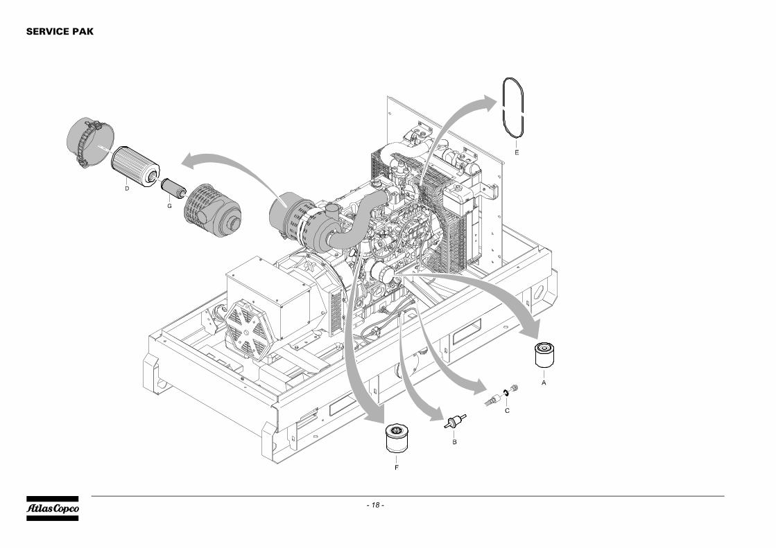
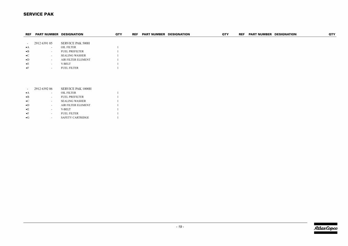
- 2912 6391 05 SERVICE PAK 500HA - OIL FILTER 1B - FUEL PREFILTER 1C - SEALING WASHER 1D - AIR FILTER ELEMENT 1E - V-BELT 1•F - FUEL FILTER 1
- 2912 6392 06 SERVICE PAK 1000HA - OIL FILTER 1B - FUEL PREFILTER 1C - SEALING WASHER 1D - AIR FILTER ELEMENT 1E - V-BELT 1•F - FUEL FILTER 1G - SAFETY CARTRIDGE 1
EF PART NUMBER DESIGNATION QTY REF PART NUMBER DESIGNATION
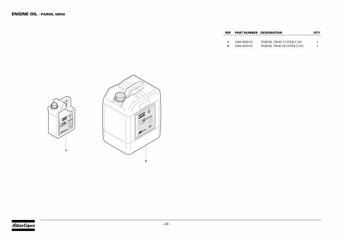
ENGINE OIL - PAROIL 5W40
PART NUMBER DESIGNATION QTY
1604 6060 01 PAROIL 5W40 5 LITER CAN 11604 6059 01 PAROIL 5W40 20 LITER CAN 1
- 20 -
REF
AB
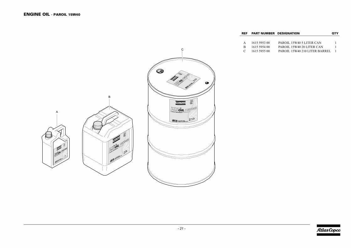
REF PART NUMBER DESIGNATION QTY
A 1615 5953 00 PAROIL 15W40 5 LITER CAN 1B 1615 5954 00 PAROIL 15W40 20 LITER CAN 1C 1615 5955 00 PAROIL 15W40 210 LITER BARREL 1
E
- 21 -
NGINE OIL - PAROIL 15W40

ENGINE COOLANT - PARCOOL EG
PART NUMBER DESIGNATION QTY
1604 5308 00 PARCOOL EG 5 LITER CAN 11604 5307 01 PARCOOL EG 20 LITER CAN 11604 5306 00 PARCOOL EG 210 LITER BARREL 1
D 1604 8159 00 PARCOOL EG CONCENTRATE 15 LITER CAN
- 22 -
REF
ABC
REF PART NUMBER DESIGNATION QTY
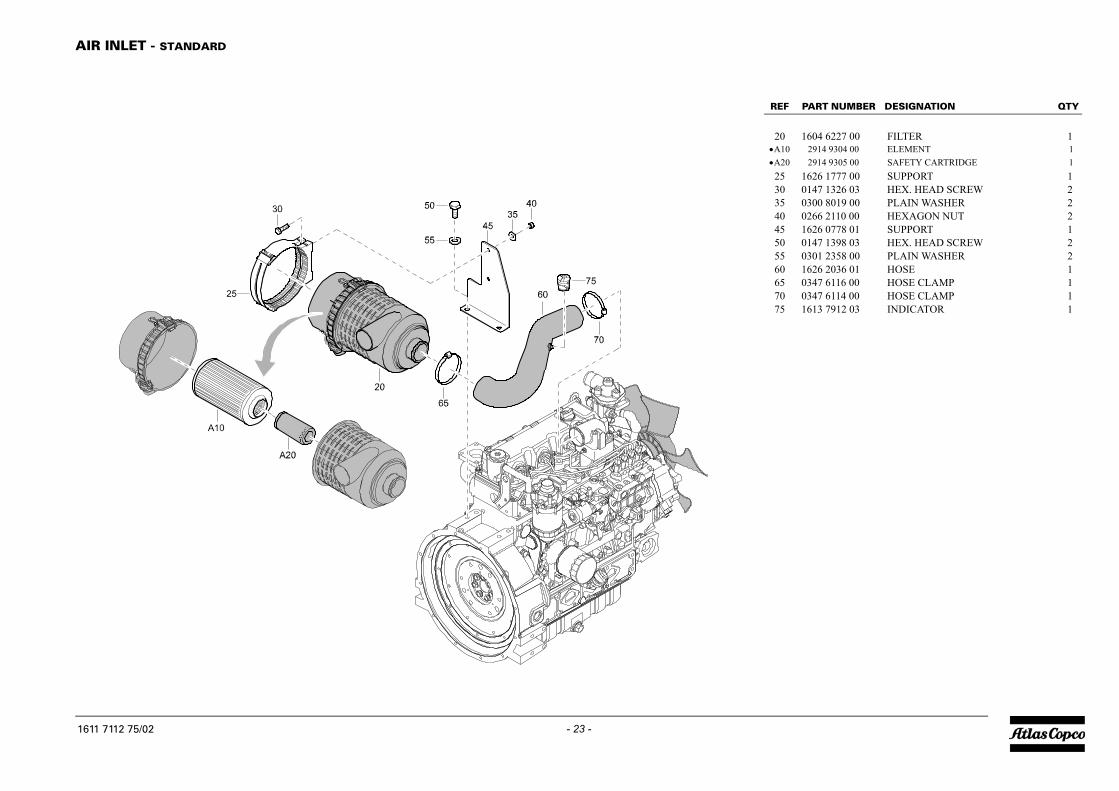
20 1604 6227 00 FILTER 1•A10 2914 9304 00 ELEMENT 1•A20 2914 9305 00 SAFETY CARTRIDGE 125 1626 1777 00 SUPPORT 130 0147 1326 03 HEX. HEAD SCREW 235 0300 8019 00 PLAIN WASHER 240 0266 2110 00 HEXAGON NUT 245 1626 0778 01 SUPPORT 150 0147 1398 03 HEX. HEAD SCREW 255 0301 2358 00 PLAIN WASHER 260 1626 2036 01 HOSE 165 0347 6116 00 HOSE CLAMP 170 0347 6114 00 HOSE CLAMP 175 1613 7912 03 INDICATOR 1
A
16
- 23 -IR INLET - STANDARD
1611 7112 75_02
11 7112 75/02
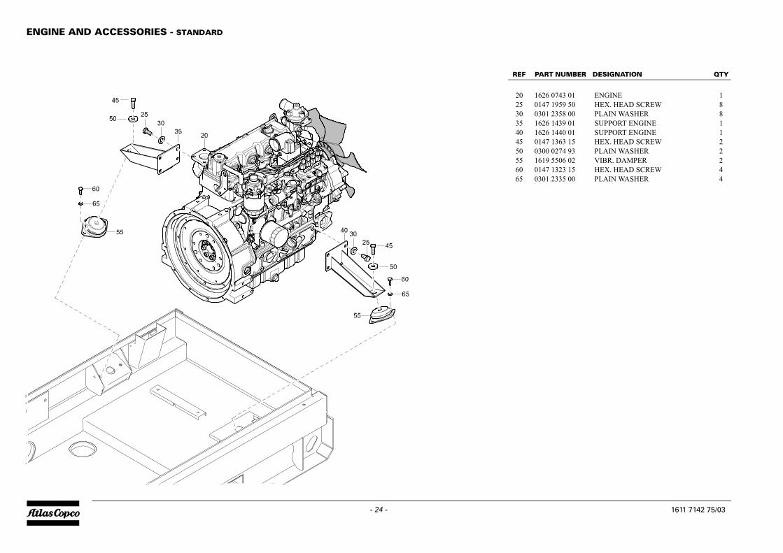
ENGINE AND ACCESSORIES - STANDARD
PART NUMBER DESIGNATION QTY
1626 0743 01 ENGINE 10147 1959 50 HEX. HEAD SCREW 80301 2358 00 PLAIN WASHER 8
35 1626 1439 01 SUPPORT ENGINE 140 1626 1440 01 SUPPORT ENGINE 145 0147 1363 15 HEX. HEAD SCREW 250 0300 0274 93 PLAIN WASHER 255 1619 5506 02 VIBR. DAMPER 260 0147 1323 15 HEX. HEAD SCREW 465 0301 2335 00 PLAIN WASHER 4
1611 7142 75/03
- 24 -1611 7142 75_03
REF
202530
REF PART NUMBER DESIGNATION QTY
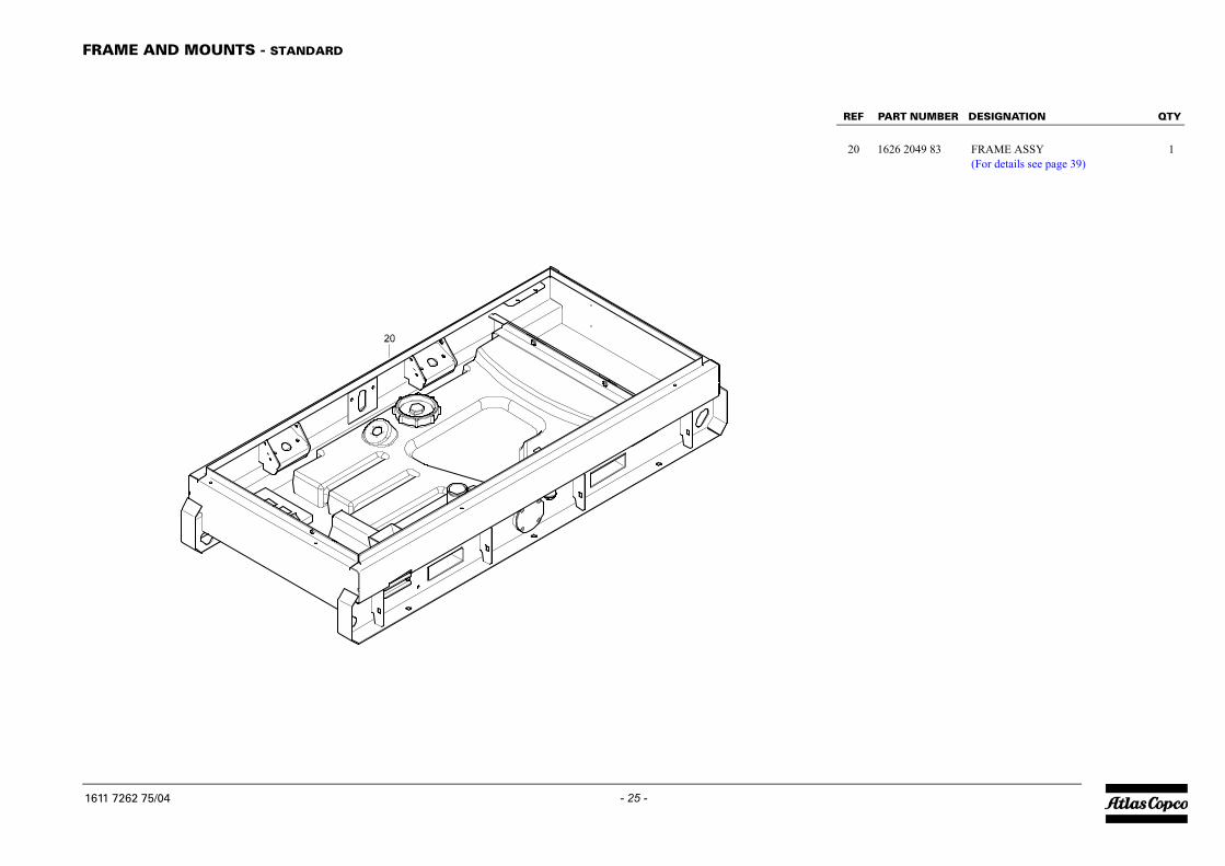
20 1626 2049 83 FRAME ASSY 1(For details see page 39)
FR
16
- 25 -AME AND MOUNTS - STANDARD
1611 7262 75_04
11 7262 75/04
COOLING SYSTEM - STANDARD
1611 7172 75_06
1611 7172 75/06
- 26 -
QTY REF PART NUMBER DESIGNATION QTY
C
223344556677889911111111111111111
R
16
- 27 -OOLING SYSTEM - STANDARD
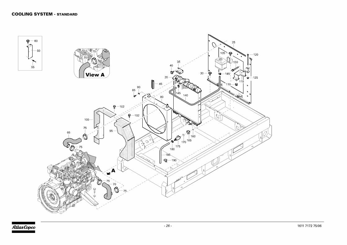
0 1626 0745 00 COOLER 15 1626 1488 02 PLATE 10 1615 5664 00 HEX. HEAD SCREW 85 1626 1084 00 BRACKET 20 1615 5664 00 HEX. HEAD SCREW 45 1619 2665 00 SEAL AR0 1626 1855 00 SUPPORT 15 0129 3115 00 BLIND RIVET 40 1615 5664 00 HEX. HEAD SCREW 25 1626 2067 00 HOSE 10 1626 2068 00 HOSE 15 0347 6113 00 HOSE CLAMP 40 1626 0749 02 COWL FAN 15 0147 1246 03 HEX. HEAD SCREW 40 0301 2321 00 PLAIN WASHER 45 1626 2601 01 GUARD 100 1626 2599 01 GUARD 102 1619 2766 00 HEX. HEAD SCREW 805 1615 5664 00 HEX. HEAD SCREW 210 0291 1110 00 LOCKNUT 215 1626 2587 00 SUPPORT 120 5541 9781 00 HEX. HEAD SCREW 125 0291 1108 00 LOCKNUT 130 1619 2766 02 HEX. HEAD SREW 140 0075 4005 55 FUEL HOSE AR45 0347 6103 00 HOSE CLAMP 260 0653 9038 00 FLAT GASKET 165 0605 8701 19 BUSHING 170 0653 1070 00 FLAT GASKET 175 1615 7072 00 VALVE 180 0347 6103 00 HOSE CLAMP 185 0099 9910 29 PLASTIC TUBE AR90 0348 0101 17 CABLE TIE 1
EF PART NUMBER DESIGNATION QTY REF PART NUMBER DESIGNATION
11 7172 75/06

EXHAUST SYSTEM - FOR GENERATOR WITHOUT SPARK ARRESTER - STANDARD
PART NUMBER DESIGNATION QTY
1626 1529 02 MUFFLER 11619 2766 00 HEX. HEAD SCREW 41626 2782 00 EXHAUST 1
32 1626 2783 00 EXHAUST 135 0346 3001 02 PIPE CLAMP 240 0147 1959 42 HEX. HEAD SCREW 445 0301 2344 00 PLAIN WASHER 450 1626 2177 02 PIPE 160 1619 2766 00 HEX. HEAD SCREW 365 1626 2940 00 COVER EXHAUST 170 1626 2830 00 PROTECTION 175 1619 2766 00 HEX. HEAD SCREW 2
1611 7202 75/05
- 28 -1611 7202 75_05
REF
202530
REF PART NUMBER DESIGNATION QTY
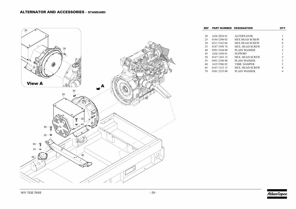
20 1626 2024 01 ALTERNATOR 125 0144 3290 03 HEX HEAD SCREW 830 0211 5162 04 HEX HEAD SCREW 835 0147 1958 74 HEX. HEAD SCREW 240 0301 2344 00 PLAIN WASHER 245 1626 1450 01 SUPPORT 150 0147 1363 15 HEX. HEAD SCREW 255 0301 2344 00 PLAIN WASHER 260 1619 5506 02 VIBR. DAMPER 265 0147 1323 15 HEX. HEAD SCREW 470 0301 2335 00 PLAIN WASHER 4
A
16
- 29 -LTERNATOR AND ACCESSORIES - STANDARD
1611 7232 75_03
11 7232 75/03

BODYWORK - STANDARD
1611 7292 75_04
1611 7292 75/04
- 30 -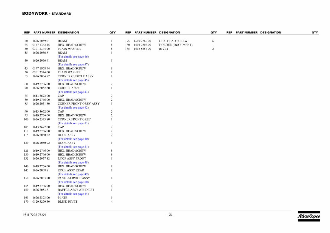
612
QTY REF PART NUMBER DESIGNATION QTY
B
2233
4
455
67
788
991
111
1
111
11
1
11
11
R
16
- 31 -ODYWORK - STANDARD
0 1626 2059 01 BEAM 15 0147 1362 15 HEX. HEAD SCREW 80 0301 2344 00 PLAIN WASHER 85 1626 2056 81 BEAM 1
(For details see page 46)0 1626 2056 91 BEAM 1
(For details see page 47)5 0147 1958 74 HEX. HEAD SCREW 80 0301 2344 00 PLAIN WASHER 85 1626 2054 82 CORNER CUBICLE ASSY 1
(For details see page 45)0 1619 2766 00 HEX. HEAD SCREW 20 1626 2052 80 CORNER ASSY 1
(For details see page 43)5 1613 3672 00 CAP 20 1619 2766 00 HEX. HEAD SCREW 25 1626 2051 80 CORNER FRONT GREY ASSY 1
(For details see page 42)0 1613 3672 00 CAP 25 1619 2766 00 HEX. HEAD SCREW 200 1626 2573 80 CORNER FRONT GREY 1
(For details see page 51)05 1613 3672 00 CAP 210 1619 2766 00 HEX. HEAD SCREW 215 1626 2050 82 DOOR ASSY 2
(For details see page 40)20 1626 2050 92 DOOR ASSY 1
(For details see page 41)25 1619 2766 00 HEX. HEAD SCREW 830 1619 2766 00 HEX. HEAD SCREW 835 1626 2057 82 ROOF ASSY FRONT 1
(For details see page 48)40 1619 2766 00 HEX. HEAD SCREW 845 1626 2058 81 ROOF ASSY REAR 1
(For details see page 49)50 1626 2063 80 PANEL SERVICE ASSY 1
(For details see page 50)55 1619 2766 00 HEX. HEAD SCREW 460 1626 2053 81 BAFFLE ASSY AIR INLET 1
(For details see page 44)65 1626 2373 00 PLATE 170 0129 3270 30 BLIND RIVET 4
175 1619 2766 00 HEX. HEAD SCREW180 1604 2206 00 HOLDER (DOCUMENT)185 1615 5556 00 RIVET
EF PART NUMBER DESIGNATION QTY REF PART NUMBER DESIGNATION
11 7292 75/04

FUEL SYSTEM - STANDARD
PART NUMBER DESIGNATION QTY
1089 0659 17 SENSOR LEVEL 11604 4137 00 HOSE CLIP 10075 4005 55 FUEL HOSE AR
50 1604 4137 00 HOSE CLIP 255 0075 4005 55 FUEL HOSE AR65 1619 2766 00 HEX. HEAD SCREW 270 1604 4137 00 HOSE CLIP 275 0075 4005 55 FUEL HOSE AR80 1604 4137 00 HOSE CLIP 185 0071 8401 63 FUEL HOSE AR90 0347 6102 00 HOSE CLAMP 295 1604 5014 00 HOSE NIPPLE 1100 0075 4005 55 FUEL HOSE AR105 1604 4137 00 HOSE CLIP 2110 1626 1866 01 HOSE 1115 0347 6131 00 HOSE CLAMP 2120 1615 6947 00 COVER 1
1611 7312 75/03
- 32 -1611 7312 75_03
Engine Part
REF
103540
REF PART NUMBER DESIGNATION QTY
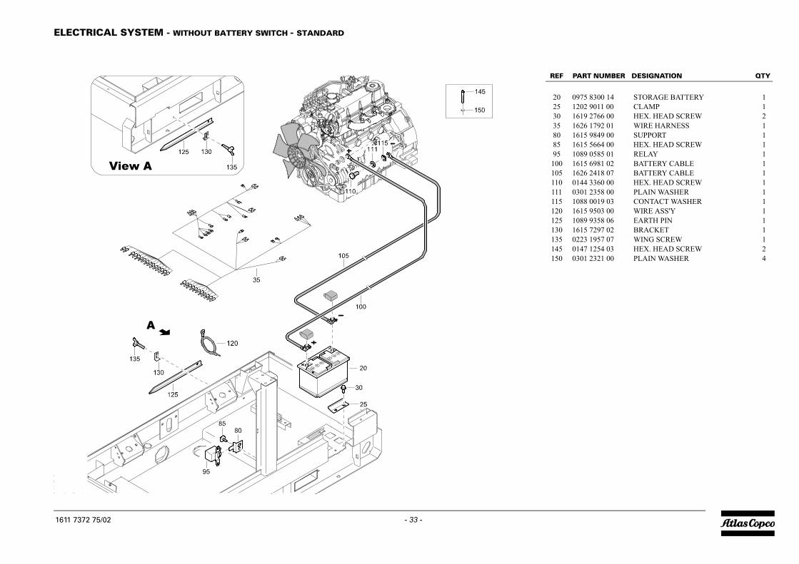
20 0975 8300 14 STORAGE BATTERY 125 1202 9011 00 CLAMP 130 1619 2766 00 HEX. HEAD SCREW 235 1626 1792 01 WIRE HARNESS 180 1615 9849 00 SUPPORT 185 1615 5664 00 HEX. HEAD SCREW 195 1089 0585 01 RELAY 1100 1615 6981 02 BATTERY CABLE 1105 1626 2418 07 BATTERY CABLE 1110 0144 3360 00 HEX. HEAD SCREW 1111 0301 2358 00 PLAIN WASHER 1115 1088 0019 03 CONTACT WASHER 1120 1615 9503 00 WIRE ASS'Y 1125 1089 9358 06 EARTH PIN 1130 1615 7297 02 BRACKET 1135 0223 1957 07 WING SCREW 1145 0147 1254 03 HEX. HEAD SCREW 2150 0301 2321 00 PLAIN WASHER 4
E
16
- 33 -LECTRICAL SYSTEM - WITHOUT BATTERY SWITCH - STANDARD
1611 7372 75_02
11 7372 75/02
MARKINGS - STANDARD
1611 7432 75_05
1611 7432 75/05
- 34 -
QTY REF PART NUMBER DESIGNATION QTY
M
2
23344556
R
16
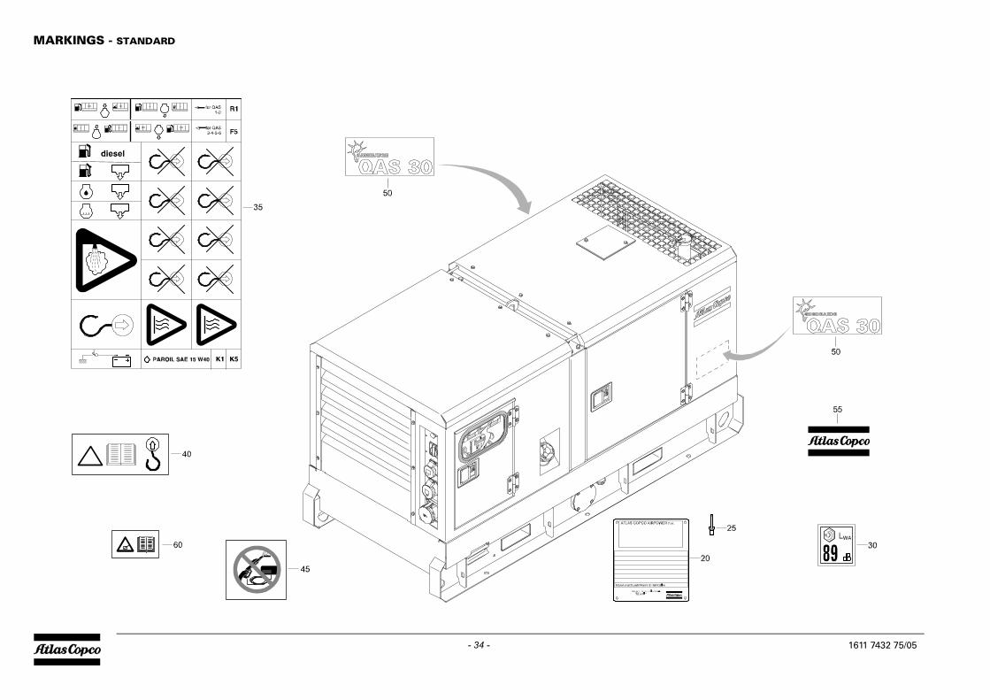
- 35 -ARKINGS - STANDARD
0 - DATA PLATE 1(Not available separately)
5 0129 3270 34 BLIND RIVET 40 1604 3317 15 LABEL NOISE 15 1079 9901 87 LABEL 10 1079 9902 58 WARNING LABEL 15 1079 9903 61 LABEL 10 1626 2415 00 LABEL 25 0690 1101 25 HOUSE MARK 10 1079 9902 63 WARNING LABEL 1
EF PART NUMBER DESIGNATION QTY REF PART NUMBER DESIGNATION
11 7432 75/05
CUBICLE AND ACCESSORIES - 400V - STANDARD
PART NUMBER DESIGNATION QTY
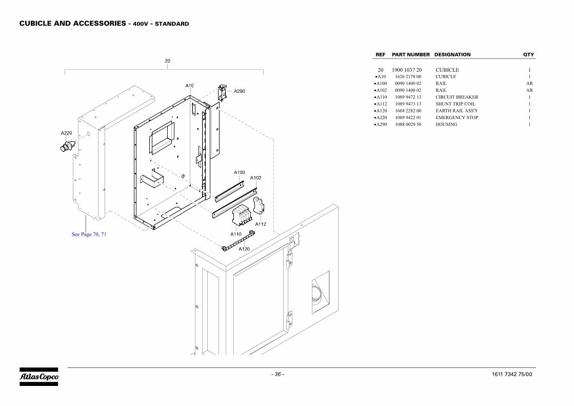
1900 1037 20 CUBICLE 11626 2178 00 CUBICLE 10090 1400 02 RAIL AR
•A102 0090 1400 02 RAIL AR•A110 1089 9472 13 CIRCUIT BREAKER 1•A112 1089 9473 13 SHUNT TRIP COIL 1•A120 1604 2282 00 EARTH RAIL ASS'Y 1•A220 1089 9422 01 EMERGENCY STOP 1•A290 1088 0029 50 HOUSING 1
1611 7342 75/00
- 36 -1611 7342 75_00
See Page 70, 71
REF
20•A10 •A100
REF PART NUMBER DESIGNATION QTY
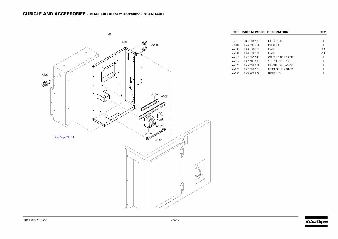
20 1900 1037 21 CUBICLE 1•A10 1626 2178 00 CUBICLE 1•A100 0090 1400 02 RAIL AR•A102 0090 1400 02 RAIL AR•A110 1089 9472 45 CIRCUIT BREAKER 1•A112 1089 9473 13 SHUNT TRIP COIL 1•A120 1604 2282 00 EARTH RAIL ASS'Y 1•A220 1089 9422 01 EMERGENCY STOP 1•A290 1088 0029 50 HOUSING 1
C
16
- 37 -UBICLE AND ACCESSORIES - DUAL FREQUENCY 400/480V - STANDARD
1611 8587 75_00
See Page 70, 71
11 8587 75/00

OIL SYSTEM - STANDARD
PART NUMBER DESIGNATION QTY
1615 6949 00 HOSE ASSEMBLY 10661 1035 00 SEALING WASHER 10686 3716 02 HEXAGON PLUG 1
35 0661 1033 00 SEALING WASHER 140 1079 3461 02 HOSE CLIP 145 0129 3111 00 BLIND RIVET 1
1611 7400 75/02
- 38 -1611 7400 75_02
REF
202530

REF PART NUMBER DESIGNATION QTY
- 1626 2049 83 FRAME ASSY (From page 25)•20 1626 2049 03 FRAME 1•25 1626 1431 82 TANK FUEL 1
(For details see page 52)•30 1626 2172 00 SUPPORT 1•35 1615 5664 00 HEX. HEAD SCREW 2•40 1626 2167 00 SUPPORT 1•45 1615 5664 00 HEX. HEAD SCREW 2•50 1626 1990 00 PLATE 1•55 1626 1991 00 SEAL 1•60 1619 2766 00 HEX. HEAD SCREW 6•65 1626 1999 00 FLANGE 2•70 1604 6550 00 GASKET 2•75 0216 1320 00 HEX. SOCKET SCREW 8•80 1626 2356 00 CLAMP 1•85 1619 2766 00 HEX. HEAD SCREW 2•90 0686 3716 09 HEXAGON PLUG 1•95 0661 1056 00 SEALING WASHER 1•100 0129 3270 49 RIVET BLIND 4•105 1626 2167 01 SUPPORT 1
FR
16
- 39 -AME ASSEMBLY - STANDARD
1626 2049 83_00
26 2049 83/00

DOOR ASSEMBLY - STANDARD
PART NUMBER DESIGNATION QTY
1626 2050 82 DOOR ASSY (From page 30)1626 2050 02 DOOR 1
- INSULATION 1SILENCING FOAM (30 mm)
•30 - INSULATION 1SILENCING FOAM (30 mm)
•35 1615 6967 03 HANDLE 1•40 0301 2321 00 PLAIN WASHER 4•45 0291 1108 00 LOCKNUT 4•50 1604 3431 00 HINGE 2•55 1615 5684 00 BRACKET 2•60 0216 1324 03 HEX SOCK. SCREW 4•65 1604 4317 00 SEAL AR
- 1079 0003 32 SILENCING FOAM2000 mm x 1500 mm x 30 mm
1626 2050 82/01
- 40 -1626 2050 82_01
REF
-•20•25

REF PART NUMBER DESIGNATION QTY
- 1626 2050 92 DOOR ASSY (From page 30)•20 1626 2050 02 DOOR 1•25 - INSULATION 1
SILENCING FOAM (30 mm)•30 - INSULATION 1
SILENCING FOAM (30 mm)•35 1615 6967 03 HANDLE 1•40 0301 2321 00 PLAIN WASHER 4•45 0291 1108 00 LOCKNUT 4•50 1604 3429 00 HINGE 2•55 1615 5684 00 BRACKET 2•60 0216 1324 03 HEX SOCK. SCREW 4•65 1604 4317 00 SEAL AR
- 1079 0003 32 SILENCING FOAM2000 mm x 1500 mm x 30 mm
D
16
- 41 -OOR ASSEMBLY - STANDARD
1626 2050 92_01
26 2050 92/01

CORNER ASSEMBLY - FRONT LEFT - STANDARD
PART NUMBER DESIGNATION QTY
1626 2051 80 CORNER FRONT (From page 30)GREY ASSY
1626 2051 00 CORNER 1•25 - INSULATION 1
SILENCING FOAM (30 mm)•30 - INSULATION 1
SILENCING FOAM (30 mm)•35 1604 3428 00 HINGE 2•40 1615 5684 00 BRACKET 2•45 0216 1324 03 HEX SOCK. SCREW 2•50 1619 2766 00 HEX. HEAD SCREW 2•55 1615 7057 00 SEAL AR•60 0690 1125 01 HOUSEMARK 1
- 1079 0003 32 SILENCING FOAM2000 mm x 1500 mm x 30 mm
1626 2051 80/02
- 42 -1626 2051 80_02
REF
-
•20
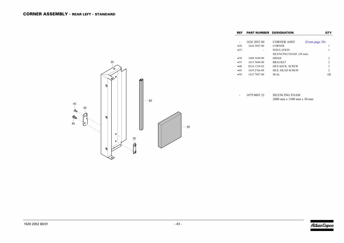
REF PART NUMBER DESIGNATION QTY
- 1626 2052 80 CORNER ASSY (From page 30)•20 1626 2052 00 CORNER 1•25 - INSULATION 1
SILENCING FOAM (30 mm)•30 1604 3430 00 HINGE 2•35 1615 5684 00 BRACKET 2•40 0216 1324 03 HEX SOCK. SCREW 2•45 1619 2766 00 HEX. HEAD SCREW 2•50 1615 7057 00 SEAL AR
- 1079 0003 32 SILENCING FOAM2000 mm x 1500 mm x 30 mm
C
16
- 43 -ORNER ASSEMBLY - REAR LEFT - STANDARD
1626 2052 80_01
26 2052 80/01
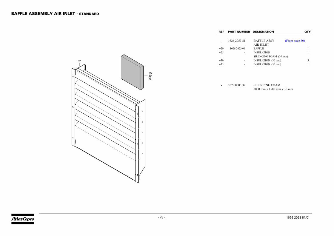
BAFFLE ASSEMBLY AIR INLET - STANDARD
PART NUMBER DESIGNATION QTY
1626 2053 81 BAFFLE ASSY (From page 30)AIR INLET
1626 2053 01 BAFFLE 1•25 - INSULATION 1
SILENCING FOAM (30 mm)•30 - INSULATION (30 mm) 5•35 - INSULATION (30 mm) 1
- 1079 0003 32 SILENCING FOAM2000 mm x 1500 mm x 30 mm
1626 2053 81/01
- 44 -1626 2053 81_01
REF
-
•20
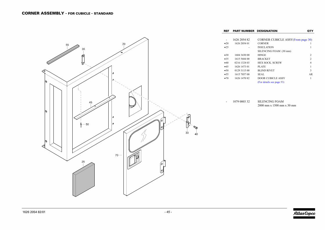
REF PART NUMBER DESIGNATION QTY
- 1626 2054 82 CORNER CUBICLE ASSY(From page 30)•20 1626 2054 01 CORNER 1•25 - INSULATION 1
SILENCING FOAM (30 mm)•30 1604 3430 00 HINGE 2•35 1615 5684 00 BRACKET 2•40 0216 1324 03 HEX SOCK. SCREW 4•45 1626 1473 01 PLATE 1•50 0129 3115 00 BLIND RIVET 3•55 1615 7057 00 SEAL AR•70 1626 1470 82 DOOR CUBICLE ASSY 1
(For details see page 53)
- 1079 0003 32 SILENCING FOAM2000 mm x 1500 mm x 30 mm
C
16
- 45 -ORNER ASSEMBLY - FOR CUBICLE - STANDARD
1626 2054 82_01
26 2054 82/01

BEAM - STANDARD
PART NUMBER DESIGNATION QTY
1626 2056 81 BEAM (From page 30)1626 2056 01 BEAM 11604 5031 00 BRACKET 2
•30 0215 0006 30 SCREW 4•35 1626 2377 00 SPACER 2•40 0291 1108 00 LOCKNUT 4
1626 2056 81/01
- 46 -1626 2056 81_01
REF
-•20•25

REF PART NUMBER DESIGNATION QTY
- 1626 2056 91 BEAM (From page 30)•20 1626 2056 01 BEAM 1•25 1604 5031 00 BRACKET 1•30 0215 0006 30 SCREW 2•35 1626 2377 00 SPACER 2•40 0291 1108 00 LOCKNUT 2
B
16
- 47 -EAM - STANDARD
1626 2056 91_01
26 2056 91/01

FRONT ROOF ASSEMBLY - STANDARD
PART NUMBER DESIGNATION QTY
1626 2057 82 ROOF ASSY FRONT (From page 30)1626 2057 02 ROOF 1
- INSULATION 1SILENCING FOAM (30 mm)
•30 - INSULATION (30 mm) 1•35 1604 2338 02 SUPPORT 2•40 1619 2766 00 HEX. HEAD SCREW 2•45 1626 2616 00 SEAL 1•50 1615 9058 01 COVER 1•65 1619 2766 00 HEX. HEAD SCREW 2
- 1079 0003 32 SILENCING FOAM2000 mm x 1500 mm x 30 mm
1626 2057 82/02
- 48 -1626 2057 82_02
REF
-•20•25

REF PART NUMBER DESIGNATION QTY
- 1626 2058 81 ROOF ASSY REAR (From page 30)•20 1626 2058 01 ROOF 1•25 - INSULATION (30 mm) 1•30 - INSULATION (30 mm) 1•35 1604 2338 02 SUPPORT 2•40 1619 2766 00 HEX. HEAD SCREW 2
- 1079 0003 32 SILENCING FOAM2000 mm x 1500 mm x 30 mm
R
16
- 49 -EAR ROOF ASSEMBLY - STANDARD
1626 2058 81_01
26 2058 81/01

SERVICE PANEL ASSEMBLY - STANDARD
PART NUMBER DESIGNATION QTY
1626 2063 80 PANEL SERVICE ASSY(From page 30)1626 2063 00 PANEL 1
- INSULATION (30 mm) 1•30 0690 1125 00 HOUSE MARK 1•35 1079 9921 76 LABEL WEBSITE 1
- 1079 0003 32 SILENCING FOAM2000 mm x 1500 mm x 30 mm
1626 2063 80/02
- 50 -1626 2063 80_02
REF
-•20•25

REF PART NUMBER DESIGNATION QTY
- 1626 2573 80 CORNER FRONT GREY(From page 30)•20 1626 2573 00 CORNER 1•25 - INSULATION 1
SILENCING FOAM (30 mm)•30 - INSULATION 1
SILENCING FOAM (30 mm)•35 1604 3430 00 HINGE 2•40 1615 5684 00 BRACKET 2•45 0216 1324 03 HEX SOCK. SCREW 2•50 1619 2766 00 HEX. HEAD SCREW 2•55 1615 7057 00 SEAL AR•60 0690 1125 01 HOUSEMARK 1
- 1079 0003 32 SILENCING FOAM2000 mm x 1500 mm x 30 mm
C
16
- 51 -ORNER ASSEMBLY - FRONT RIGHT - STANDARD
1626 2573 80_02
26 2573 80/02
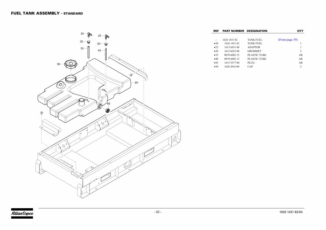
FUEL TANK ASSEMBLY - STANDARD
PART NUMBER DESIGNATION QTY
1626 1431 82 TANK FUEL (From page 39)1626 1431 02 TANK FUEL 11615 6651 00 ADAPTOR 1
•30 1615 6652 00 GROMMET 2•35 0070 6002 15 PLASTIC TUBE AR•40 0070 6002 15 PLASTIC TUBE AR•45 1615 5577 00 PLUG AR•50 1626 2016 00 CAP 2
1626 1431 82/00
- 52 -1626 1431 82_00
REF
-•20•25
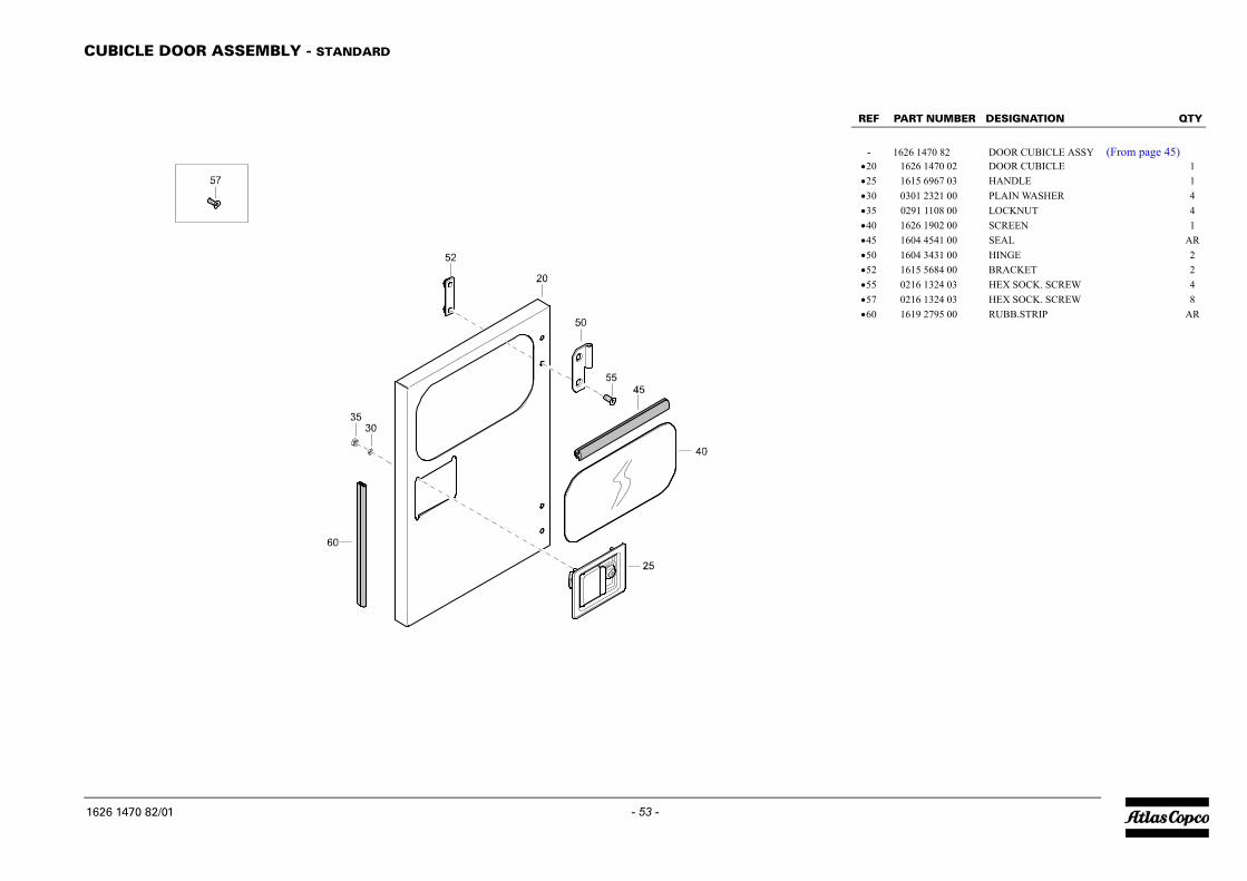
REF PART NUMBER DESIGNATION QTY
- 1626 1470 82 DOOR CUBICLE ASSY (From page 45)•20 1626 1470 02 DOOR CUBICLE 1•25 1615 6967 03 HANDLE 1•30 0301 2321 00 PLAIN WASHER 4•35 0291 1108 00 LOCKNUT 4•40 1626 1902 00 SCREEN 1•45 1604 4541 00 SEAL AR•50 1604 3431 00 HINGE 2•52 1615 5684 00 BRACKET 2•55 0216 1324 03 HEX SOCK. SCREW 4•57 0216 1324 03 HEX SOCK. SCREW 8•60 1619 2795 00 RUBB.STRIP AR
C
16
- 53 -UBICLE DOOR ASSEMBLY - STANDARD
1626 1470 82_01
26 1470 82/01

VALVE AND FITTINGS - FOR GENERATOR WITH EXTERNAL FUEL TANK CONNECTION - OPTIONS
1611 7122 75_01
1611 7122 75/01
- 54 -
QTY REF PART NUMBER DESIGNATION QTY
V
2234455667779911
R
16
- 55 -ALVE AND FITTINGS - FOR GENERATOR WITH EXTERNAL FUEL TANK CONNECTION - OPTIONS
0 1626 2625 00 SUPPORT 15 1615 5664 00 HEX. HEAD SCREW 40 1079 9925 00 INFORMATION LABEL 10 1604 6111 00 VALVE 15 0147 1363 03 HEX. HEAD SCREW 20 0301 2344 00 PLAIN WASHER 45 0266 2111 00 HEXAGON NUT 20 0653 1124 00 FLAT GASKET 45 0571 0020 14 HOSE NIPPLE 10 0075 4005 55 FUEL HOSE AR5 1604 4137 00 HOSE CLIP 28 0571 0020 14 HOSE NIPPLE 10 0571 0020 14 HOSE NIPPLE 15 0075 4005 55 FUEL HOSE AR00 1604 4137 00 HOSE CLIP 220 0571 0020 14 HOSE NIPPLE 1
EF PART NUMBER DESIGNATION QTY REF PART NUMBER DESIGNATION
11 7122 75/01

QUICK COUPLINGS - FOR GENERATOR WITH EXTERNAL FUEL TANK CONNECTION - OPTIONS
1611 7125 75_00
1611 7125 75/00
- 56 -
QTY REF PART NUMBER DESIGNATION QTY
Q
223344556678899111
R
16
- 57 -UICK COUPLINGS - FOR GENERATOR WITH EXTERNAL FUEL TANK CONNECTION - OPTIONS
0 1626 2382 00 SUPPORT 15 1615 5664 00 HEX. HEAD SCREW 20 1615 8745 01 QUICK COUPLING 15 0653 1165 00 FLAT GASKET 20 0605 8700 37 BUSHING 15 0560 0305 04 ELBOW 10 0571 0020 15 HOSE NIPPLE 15 0347 6103 00 HOSE CLAMP 20 0071 8402 90 FUEL HOSE AR5 0571 0020 15 HOSE NIPPLE 10 0560 0200 23 ELBOW 10 1615 8744 01 QUICK COUPLING 15 0653 1124 00 FLAT GASKET 20 0560 0200 23 ELBOW 15 0571 0020 15 HOSE NIPPLE 100 0347 6103 00 HOSE CLAMP 205 0071 8402 90 FUEL HOSE AR10 0560 0200 23 ELBOW 1
EF PART NUMBER DESIGNATION QTY REF PART NUMBER DESIGNATION
11 7125 75/00

BATTERY CHARGER - OPTIONS
PART NUMBER DESIGNATION QTY
1900 1037 49 BATTERY CHARG. 11089 0697 01 BATTERY CHARGER 10090 1400 02 RAIL AR
1611 7130 75/01
- 58 -1611 7130 75_01
REF
20•A490 •A492

REF PART NUMBER DESIGNATION QTY
20 0571 0020 79 NIPPLE 125 0347 6106 00 HOSE CLAMP 130 0072 8403 16 HOSE AR35 0347 6106 00 HOSE CLAMP 140 1626 2687 00 BRACKET 142 1619 2766 00 HEX. HEAD SCREW 245 1089 9403 05 COOLANT HEATER 150 0347 6106 00 HOSE CLAMP 155 0072 8403 16 HOSE AR60 0347 6106 00 HOSE CLAMP 170 0571 0020 79 NIPPLE 1
C
16
- 59 -OOLANT HEATER - OPTIONS
1611 7155 75_01
11 7155 75/01

PLUG - FOR GENERATOR WITH EXTERNAL FUEL TANK CONNECTION AND WITHOUT QUICK COUPLINGS - OPTIONS
PART NUMBER DESIGNATION QTY
0653 1124 00 FLAT GASKET 20686 3716 02 HEXAGON PLUG 2
1611 8045 85/00
- 60 -1611 8045 85_00
See Page 54
REF
2025

REF PART NUMBER DESIGNATION QTY
16A PIN EARTH20 1900 1037 59 SOCKET 1
•A546 1089 0662 29 SOCKET OUTLET 1
16A RIM EARTH20 1900 1037 58 SOCKET 1
•A546 1089 0662 01 SOCKET OUTLET 1
16A CEE20 1900 1037 57 SOCKET 1
•A546 1089 0662 11 SOCKET OUTLET 1
1611 8555 75/00
1611 8550 75/00
1611 8560 75/00
S
- 61 -
OCKET - 16A RIM EARTH, 16A PIN EARTH, 16A CEE - OPTIONS
1611 8550 75_00
1611 8555 75_00
1611 8560 75_00

TOWING EYE - DIN EYE LT, NATO EYE LT, BALL COUPLING LT - OPTIONS
PART NUMBER DESIGNATION QTY
DIN EYE LT 1615 8944 01 EYE 1
NATO EYE LT20 1615 8946 01 EYE 1
BALL COUPLING LT20 1615 8945 01 EYE 1
1611 7204 85/01
1611 7205 85/01
1611 7206 85/01
- 62 -
1611 7204 85_01
1611 7205 85_01
1611 7206 85_01
REF
20
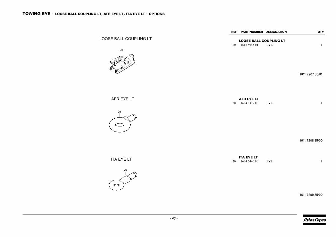
REF PART NUMBER DESIGNATION QTY
LOOSE BALL COUPLING LT 20 1615 8945 01 EYE 1
AFR EYE LT20 1604 7319 00 EYE 1
ITA EYE LT20 1604 7440 00 EYE 1
1611 7207 85/01
1611 7208 85/00
1611 7209 85/00
T
- 63 -
OWING EYE - LOOSE BALL COUPLING LT, AFR EYE LT, ITA EYE LT - OPTIONS
1611 7207 85_01
1611 7208 85_00
1611 7209 85_00

COSMOS - GLOBAL COVERAGE WITH GPRS NETWORK - OPTIONS
PART NUMBER DESIGNATION QTY
1900 1777 02 COSMOS GPRS - NO QC4001 11604 7945 00 COSMOS MODULE 11619 2765 00 SCREW 4
•A30 1604 8397 00 COSMOS WIRING 1•A50 1604 8401 00 CONVERTOR 1•A52 1604 7730 00 WIRING 130 1089 9593 97 ANTENNA 132 1088 1301 03 CABLE STRIP 534 0698 0123 00 GROMMET 1
1611 7772 85/02
- 64 -1611 7772 85_02
REF
20•A20 •A22

REF PART NUMBER DESIGNATION QTY
20 1900 1777 03 COSMOS CDMA - NO QC4001 1•A20 1604 8945 00 COSMOS MODULE 1•A22 1619 2765 00 SCREW 4•A30 1604 8397 00 COSMOS WIRING 1•A50 1604 8401 00 CONVERTOR 1•A52 1604 7730 00 WIRING 130 1089 9593 97 ANTENNA 132 1088 1301 03 CABLE STRIP 534 0698 0123 00 GROMMET 1
C
16
- 65 -OSMOS - GLOBAL COVERAGE WITH CDMA NETWORK - OPTIONS
1611 7773 85_02
11 7773 85/02

ELECTRICAL SYSTEM - WITH BATTERY SWITCH - OPTIONS
PART NUMBER DESIGNATION QTY
0975 8300 14 STORAGE BATTERY 11202 9011 00 CLAMP 11619 2766 00 HEX. HEAD SCREW 2
35 1626 1792 01 WIRE HARNESS 180 1615 9849 00 SUPPORT 195 1089 0585 01 RELAY 1100 1615 6981 02 BATTERY CABLE 1105 1626 2418 05 BATTERY CABLE 1110 1089 0584 01 BATTERY SWITCH 1115 1604 3473 02 SUPPORT 1120 1615 5664 00 HEX. HEAD SCREW 2135 1626 2418 06 BATTERY CABLE 1140 0144 3360 00 HEX. HEAD SCREW 1141 0301 2358 00 PLAIN WASHER 1145 1088 0019 03 CONTACT WASHER 1150 1615 9503 00 WIRE ASS'Y 1155 1089 9358 06 EARTH PIN 1160 1615 7297 02 BRACKET 1165 0223 1957 07 WING SCREW 1175 0147 1254 03 HEX. HEAD SCREW 2180 0301 2321 00 PLAIN WASHER 4
1611 8502 75/01
- 66 -1611 8502 75_01
REF
202530

REF PART NUMBER DESIGNATION QTY
20 1626 1529 02 MUFFLER 125 1619 2766 00 HEX. HEAD SCREW 430 1626 2782 00 EXHAUST 132 1626 2783 00 EXHAUST 135 0346 3001 02 PIPE CLAMP 240 0147 1959 42 HEX. HEAD SCREW 445 0301 2344 00 PLAIN WASHER 450 0346 3001 02 PIPE CLAMP 160 1626 3011 00 ARRESTER SPARK 165 0346 3000 21 PIPE CLAMP 170 1626 3015 00 PIPE EXHAUST 175 1619 2766 00 HEX. HEAD SCREW 380 1626 2940 00 COVER EXHAUST 185 1626 2830 00 PROTECTION 190 1619 2766 00 HEX. HEAD SCREW 2
E
16
- 67 -XHAUST SYSTEM - FOR GENERATOR WITH SPARK ARRESTER - OPTIONS
1611 8508 75_00
11 8508 75/00

UNDERCARRIAGE - OPTIONS
PART NUMBER DESIGNATION QTY
1626 2426 00 UNDER CARRIAGE 1
1611 8522 75/01
- 68 -1611 8522 75_01
REF
20

REF PART NUMBER DESIGNATION QTY
10 1626 2882 80 TANK FUEL ASSY 24H 1 (For details see page 76)
FR
16
- 69 -AME AND MOUNTS - SKID FUEL TANK - OPTIONS
1611 8524 75_00
11 8524 75/00

CUBICLE - WITH TERMINAL BOARD - OPTIONS
PART NUMBER DESIGNATION QTY
1900 1037 50 TERMINAL 11626 2185 00 PLATE 11626 2180 00 PLATE 1
•A510 1604 6174 00 TERMINAL BOARD 1•A520 1626 2414 00 SCREEN 1
1611 8540 75/00
- 70 -1611 8540 75_00
REF
20•A500 •A501

REF PART NUMBER DESIGNATION QTY
20 1900 1037 52 TERMINAL 1•A500 1626 2185 00 PLATE 1•A501 1626 2179 00 PLATE 1•A510 1604 6174 00 TERMINAL BOARD 1•A520 1626 2414 00 SCREEN 1•A532 1089 9472 27 CIRCUIT BREAKER 1•A534 1089 9472 26 CIRCUIT BREAKER 1•A536 1089 9473 01 CIRCUIT BREAKER 1•A540 1089 0662 07 SOCKET OUTLET 1•A542 1089 0662 04 SOCKET OUTLET 1•A544 1089 0662 12 SOCKET OUTLET 1
C
16
- 71 -UBICLE - WITH TERMINAL BOARD AND SOCKET - OPTIONS
1611 8546 75_00
11 8546 75/00

CONTROL PANEL - QC1002 - OPTIONS
PART NUMBER DESIGNATION QTY
1900 1037 81 CONTROL PANEL 11089 9333 04 FUSE HOLDER 11089 9332 01 FUSE 3
•A800 1626 2182 00 PLATE 1•A801 1626 2526 00 HANDGRIP 1•A810 1604 9382 00 CONTROLLER 1•A820 1089 0341 07 RELAY 2•A822 1089 0358 01 SOCKET 2•A830 1089 9381 11 AMPEREMETER 3•A832 1089 9383 01 VOLTMETER 1•A834 1089 9614 01 VOLTAGE SWITCH 1•A840 1089 9423 01 CIRCUIT BREAKER 1•A842 1089 0263 11 SELECTOR SWITCH 1•A860 1089 9354 01 PANELLIGHT 1•A862 1619 1609 00 BULB 1•A890 1088 0029 45 MALE INSERT 1•A892 1088 0029 61 MALE CONTACT 9•A894 1088 0029 55 MALE CONTACT 2
1611 8566 75/00
- 72 -1611 8566 75_00
REF
20•A420 •A422
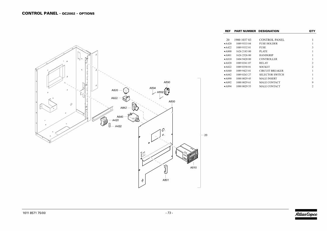
REF PART NUMBER DESIGNATION QTY
20 1900 1037 83 CONTROL PANEL 1•A420 1089 9333 04 FUSE HOLDER 1•A422 1089 9332 01 FUSE 3•A800 1626 2183 00 PLATE 1•A801 1626 2526 00 HANDGRIP 1•A810 1604 9420 00 CONTROLLER 1•A820 1089 0341 07 RELAY 2•A822 1089 0358 01 SOCKET 2•A840 1089 9423 01 CIRCUIT BREAKER 1•A842 1089 0263 27 SELECTOR SWITCH 1•A890 1088 0029 45 MALE INSERT 1•A892 1088 0029 61 MALE CONTACT 9•A894 1088 0029 55 MALE CONTACT 2
C
16
- 73 -ONTROL PANEL - QC2002 - OPTIONS
1611 8571 75_00
11 8571 75/00

EARTH LEAKAGE RELAY - OPTIONS
PART NUMBER DESIGNATION QTY
1900 1037 60 RELAY 11089 9473 54 EARTH RELAY 11089 9473 20 SWITCH 1
•A604 1089 9473 55 TORUS 1
1611 8575 75/00
- 74 -1611 8575 75_00
REF
20•A600 •A602

REF PART NUMBER DESIGNATION QTY
20 1900 1037 61 RELAY 1•A600 1089 9450 01 INSUL.MON.RELAY 1
IN
16
- 75 -SULATION MONITORING RELAY - OPTIONS
1611 8580 75_00
11 8580 75/00
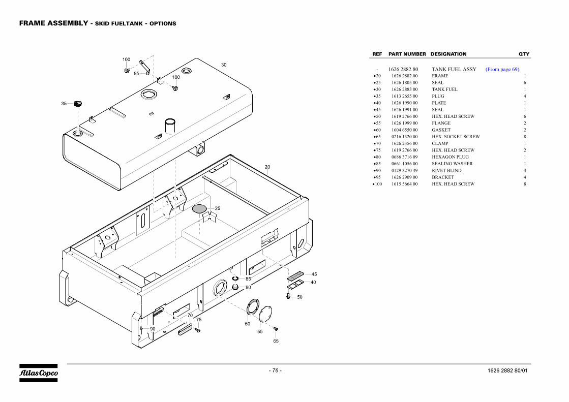
FRAME ASSEMBLY - SKID FUELTANK - OPTIONS
PART NUMBER DESIGNATION QTY
1626 2882 80 TANK FUEL ASSY (From page 69)1626 2882 00 FRAME 11626 1805 00 SEAL 6
•30 1626 2883 00 TANK FUEL 1•35 1613 2655 00 PLUG 4•40 1626 1990 00 PLATE 1•45 1626 1991 00 SEAL 1•50 1619 2766 00 HEX. HEAD SCREW 6•55 1626 1999 00 FLANGE 2•60 1604 6550 00 GASKET 2•65 0216 1320 00 HEX. SOCKET SCREW 8•70 1626 2356 00 CLAMP 1•75 1619 2766 00 HEX. HEAD SCREW 2•80 0686 3716 09 HEXAGON PLUG 1•85 0661 1056 00 SEALING WASHER 1•90 0129 3270 49 RIVET BLIND 4•95 1626 2909 00 BRACKET 4•100 1615 5664 00 HEX. HEAD SCREW 8
1626 2882 80/01
- 76 -1626 2882 80_01
REF
-•20•25