qcpu(q mode)/qnacpu programming manual (sfc)q mode)_qnacpu...qcpu (q mode)/qnacpu programming manual...
TRANSCRIPT
Programming Manual
Mitsubishi Programmable Logic Controller
QCPU(Q Mode)/QnACPU
(SFC)

A - 1 A - 1
• SAFETY CAUTIONS •(You must read these cautions before using the product.)
When using the Mitsubishi Programmable Controller MELSEC-Q/QnA Series, thoroughly read the manualassociated with the product and the related manuals introduced in the associated manual. Also pay dueattention to safety and handle the module properly.Store carefully the manual associated with the product, in a place where it is accessible for referencewhenever necessary, and forward a copy of the manual to the end user.

A - 2 A - 2
REVISIONS* The manual number is given on the bottom left of the back cover.
Print Date * Manual Number RevisionDec., 1999 SH (NA) 080041-A First editionMay, 2001 SH (NA) 080041-B Partial correction
Chapter 1, Section 3.1, Appendix 2
Apr, 2002 SH (NA) 080041-C Partial correctionChapters 1 and 2, Sections 3.1, 3.3, 5.1, 5.1.1 and 5.1.2, Appendix 2
Mar, 2003 SH (NA) 080041-D Addition of use of MELSAP3 to Basic model QCPU (first five digits ofserial No. are 04122 or later).Overall reexamination
Japanese Manual Version SH-080023-E
This manual confers no industrial property rights or any rights of any other kind, nor does it confer any patentlicenses. Mitsubishi Electric Corporation cannot be held responsible for any problems involving industrial propertyrights which may occur as a result of using the contents noted in this manual.
1999 MITSUBISHI ELECTRIC CORPORATION
A - 3 A - 3
INTRODUCTION
Thank you for purchasing the Mitsubishi MELSEC-Q/QnA Series of General Purpose ProgrammableControllers.Before using the product, please read this manual carefully to develop full familiarity with the functions andperformance of the Programmable Controller Q/QnA Series you have purchased, so as to ensure correct use.Please be sure to deliver this manual to the final user.
CONTENTS
1. GENERAL DESCRIPTION 1- 1 to 1-11
1.1 Description of SFC Program.................................................................................................................... 1- 21.2 SFC (MELSAP3) Features ...................................................................................................................... 1- 4
2. SYSTEM CONFIGURATION 2- 1 to 2- 2
3. SPECIFICATIONS 3- 1 to 3-16
3.1 Performance Specifications Related to SFC Programs ......................................................................... 3- 13.1.1 Performance specifications of Basic model QCPU.......................................................................... 3- 13.1.2 Performance specifications of High Performance model QCPU and Process CPU ...................... 3- 33.1.3 Performance specifications of QnACPU .......................................................................................... 3- 5
3.2 Device List ................................................................................................................................................ 3- 73.2.1 Device list of Basic model QCPU ..................................................................................................... 3- 73.2.2 Device list of High Performance model QCPU, Process CPU and QnACPU................................. 3- 9
3.3 Processing Time for SFC Program ........................................................................................................ 3-113.4 Calculating the SFC Program Capacity .................................................................................................. 3-15
4. SFC PROGRAM CONFIGURATION 4- 1 to 4-87
4.1 List of SFC Diagram Symbols ................................................................................................................. 4- 24.2 Steps ........................................................................................................................................................ 4- 4
4.2.1 Step (without step attribute) ......................................................................................................... 4- 44.2.2 Initial step ...................................................................................................................................... 4- 64.2.3 Dummy step .................................................................................................................................. 4- 74.2.4 Coil HOLD step SC ........................................................................................................................... 4- 74.2.5 Operation HOLD step (without transition check) SE ....................................................................... 4-104.2.6 Operation HOLD step (with transition check) ST ............................................................................ 4-124.2.7 Reset step R ..................................................................................................................................... 4-144.2.8 Block START step (with END check) .......................................................................................... 4-154.2.9 Block START step (without END check) ..................................................................................... 4-174.2.10 End step........................................................................................................................................... 4-194.2.11 Instructions that cannot be used with operation outputs ............................................................... 4-21
4.3 Transition.................................................................................................................................................. 4-224.3.1 Serial transition.................................................................................................................................. 4-234.3.2 Selection transition ............................................................................................................................ 4-254.3.3 Parallel transition............................................................................................................................... 4-284.3.4 Jump transition .................................................................................................................................. 4-324.3.5 Precautions when creating sequence programs for operation outputs (steps) and transition
conditions .......................................................................................................................................... 4-33
A - 4 A - 4
4.4 Controlling SFC Programs by Instructions (SFC Control Instructions) .................................................. 4-364.4.1 Step operation status check instructions (LD, LDI, AND, ANI, OR, ORI) ....................................... 4-404.4.2 Forced transition check instruction (LD, LDI, AND, ANI, OR, ORI)................................................. 4-424.4.3 Block operation status check instruction (LD, LDI, AND, ANI, OR, ORI)........................................ 4-444.4.4 Active step batch readout instructions (MOV, DMOV)..................................................................... 4-464.4.5 Active step batch readout (BMOV) ................................................................................................... 4-494.4.6 Block START & END instructions (SET, RST)................................................................................. 4-524.4.7 Block STOP and RESTART instructions (PAUSE, RSTART)......................................................... 4-534.4.8 Step START and END instructions (SET, RST) .............................................................................. 4-554.4.9 Forced transition EXECUTE & CANCEL instructions (SET, RST) ................................................. 4-594.4.10 Active step change instruction (SCHG).......................................................................................... 4-614.4.11 Block switching instruction (BRSET) .............................................................................................. 4-62
4.5 SFC Information Devices......................................................................................................................... 4-644.5.1 Block START/END bit ....................................................................................................................... 4-654.5.2 Step transition bit............................................................................................................................... 4-674.5.3 Block STOP/RESTART bit................................................................................................................ 4-694.5.4 Block STOP mode bit........................................................................................................................ 4-714.5.5 Continuous transition bit.................................................................................................................... 4-734.5.6 Number of active steps register ........................................................................................................ 4-75
4.6 Step Transition Watch dog Timer............................................................................................................ 4-764.7 SFC Operation Mode Setting .................................................................................................................. 4-78
4.7.1 SFC program start mode .................................................................................................................. 4-794.7.2 Block 0 START condition .................................................................................................................. 4-814.7.3 Output mode at block STOP............................................................................................................. 4-824.7.4 Periodic execution block setting ....................................................................................................... 4-834.7.5 Operation mode at double block START ......................................................................................... 4-844.7.6 Operation mode at transition to active step (double step START).................................................. 4-85
5. SFC PROGRAM PROCESSING SEQUENCE 5- 1 to 5-14
5.1 Whole Program Processing of Basic Model QCPU................................................................................ 5- 15.1.1 Whole program processing sequence.............................................................................................. 5- 1
5.2 Whole Program Processing of High Performance Model QCPU/Process CPU/QnACPU ................... 5- 25.2.1 Whole program processing sequence.............................................................................................. 5- 25.2.2 Execution type designation by instructions ...................................................................................... 5- 45.2.3 SFC program for program execution management ......................................................................... 5- 6
5.3 SFC Program Processing Sequence ...................................................................................................... 5- 85.3.1 SFC program execution .................................................................................................................... 5- 85.3.2 Block execution sequence ................................................................................................................ 5-105.3.3 Step execution sequence.................................................................................................................. 5-115.3.4 Continuous transition ON/OFF operation......................................................................................... 5-12

A - 5 A - 5
6. SFC PROGRAM EXECUTION 6- 1 to 6-15
6.1 SFC Program START And STOP ........................................................................................................... 6- 16.1.1 SFC program resumptive START procedure................................................................................... 6- 2
6.2 Block START and END............................................................................................................................ 6- 46.2.1 Block START methods...................................................................................................................... 6- 46.2.2 Block END methods .......................................................................................................................... 6- 5
6.3 Block Temporary Stop and Restart Methods.......................................................................................... 6- 66.3.1 Block STOP methods........................................................................................................................ 6- 66.3.2 Restarting a stopped block ............................................................................................................... 6- 9
6.4 Step START (Activate) and END (Deactivate) Methods ........................................................................ 6-106.4.1 Step START (activate) methods....................................................................................................... 6-106.4.2 Step END (deactivate) methods ....................................................................................................... 6-116.4.3 Changing an active step status (Cannot be used for Basic model QCPU)..................................... 6-12
6.5 Operation Methods for Continuous Transition ........................................................................................ 6-136.6 Operation at Program Change ................................................................................................................ 6-14
APPENDICES APP- 1 to APP-20
APPENDIX 1 SPECIAL RELAY AND SPECIAL REGISTER LIST.......................................................APP- 11.1 “SM” Special Relays........................................................................................................................APP- 11.2 “SD” Special Registers....................................................................................................................APP- 5
APPENDIX 2 MELSAP-II AND MELSAP3 COMPARISON ..................................................................APP-10APPENDIX 3 Restrictions on Basic Model QCPU and Replacement Methods ...................................APP-16
3.1 Step Transition Watchdog Timer Replacement Method................................................................APP-173.2 Fixed-Cycle Execution Block Replacement Method......................................................................APP-183.3 Forced Transition Bit (TRn) Replacement Method ........................................................................APP-193.4 Active Step Change Instruction (SCHG) Replacement Method....................................................APP-20
A - 6 A - 6
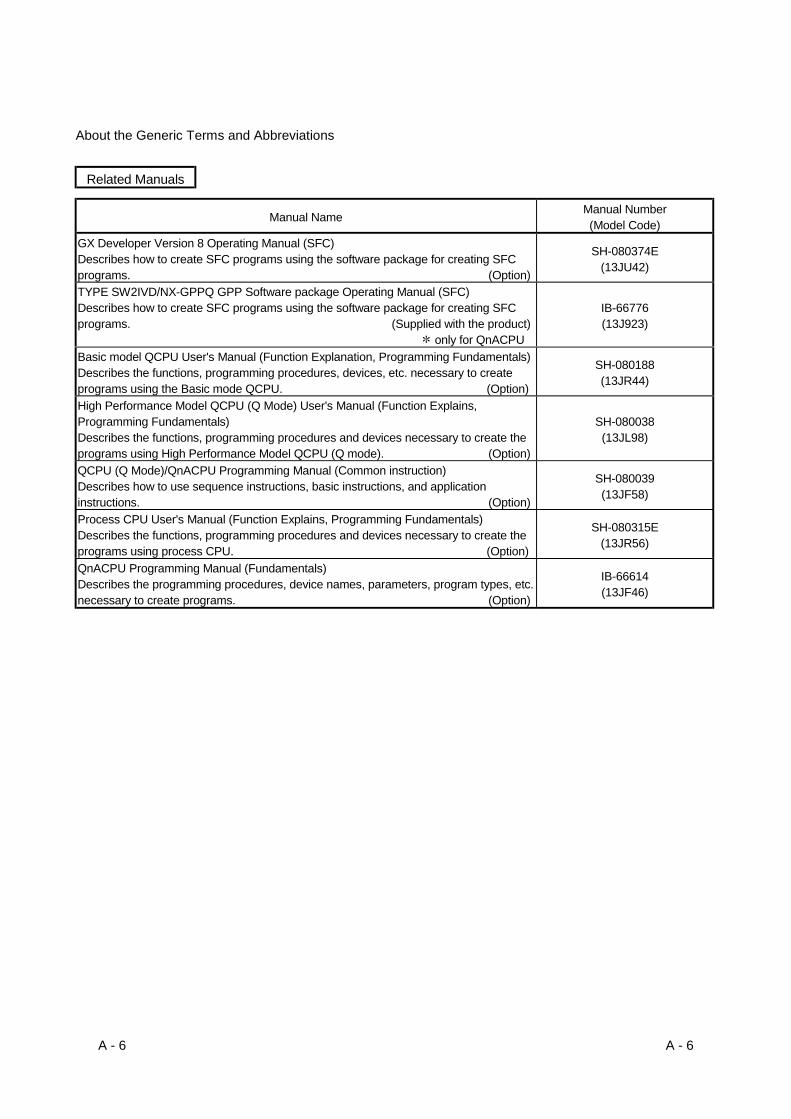
About the Generic Terms and Abbreviations
Related Manuals
Manual Name Manual Number(Model Code)
GX Developer Version 8 Operating Manual (SFC)Describes how to create SFC programs using the software package for creating SFCprograms. (Option)
SH-080374E(13JU42)
TYPE SW2IVD/NX-GPPQ GPP Software package Operating Manual (SFC)Describes how to create SFC programs using the software package for creating SFCprograms. (Supplied with the product)
only for QnACPU
IB-66776(13J923)
Basic model QCPU User's Manual (Function Explanation, Programming Fundamentals)Describes the functions, programming procedures, devices, etc. necessary to createprograms using the Basic mode QCPU. (Option)
SH-080188(13JR44)
High Performance Model QCPU (Q Mode) User's Manual (Function Explains,Programming Fundamentals)Describes the functions, programming procedures and devices necessary to create theprograms using High Performance Model QCPU (Q mode). (Option)
SH-080038(13JL98)
QCPU (Q Mode)/QnACPU Programming Manual (Common instruction)Describes how to use sequence instructions, basic instructions, and applicationinstructions. (Option)
SH-080039(13JF58)
Process CPU User's Manual (Function Explains, Programming Fundamentals)Describes the functions, programming procedures and devices necessary to create theprograms using process CPU. (Option)
SH-080315E(13JR56)
QnACPU Programming Manual (Fundamentals)Describes the programming procedures, device names, parameters, program types, etc.necessary to create programs. (Option)
IB-66614(13JF46)

A - 7 A - 7
Generic terms and abbreviations used in this manual
This manual uses the following generic terms and abbreviations unless otherwisedescribed.
Generic term/abbreviation Description of generic term/abbreviation
QCPU Abbreviation of Basic model QCPU, High Performance model QCPU, process CPU
QnACPU Abbreviation of Q2ASCPU, Q2ASCPU-S1, Q2ASHCPU, Q2ASHCPU-S1, Q2ACPU,Q2ACPU-S1, Q3ACPU, Q4ACPU, Q4ARCPU
QnCPU Abbreviation of Q02CPUQnHCPU Abbreviation of Q02HCPU, Q06HCPU, Q12HCPU, Q25HCPUQnPHCPU Abbreviation of Q12PHCPU, Q25PHCPUHigh Performance modelQCPU Generic term of Q02CPU, Q02HCPU, Q06HCPU, Q12HCPU, Q25HCPU
Process CPU Generic term of Q12PHCPU, Q25PHCPUBasic model QCPU Generic term of Q00JCPU, Q00CPU, Q01CPU

1 - 1 1 - 1
MELSEC-Q/QnA1 GENERAL DESCRIPTION
1. GENERAL DESCRIPTIONSFC, an abbreviation for "Sequential Function Chart", is a control specification description formatin which a sequence of control operations is split into a series of steps to enable a clearexpression of the program execution sequence and execution conditions.
This manual describes the specifications, functions, instructions, programming procedures, etc.used to perform programming with an SFC program using MELSAP3.
MELSAP3 can be used with the following CPU modules.• Basic model QCPU (first five digits of serial No. are 04122 or later)• High Performance model QCPU• Process CPU• QnACPU
MELSAP3 conforms to the IEC Standard for SFC.In this manual, MELSAP3 is referred to as SFC (program, diagram).
POINT(1) The following functions cannot be executed if a parameter that sets the "high
speed interrupt cyclic interval" is loaded into a High Performance model QCPUof which the first 5 digits of the serial number are "04012" or later.• Step transition watch dog timer (see Section 4.6)• Periodic execution block setting (see Section 4.7.4)
(2) The Qn(H)CPU-A (A mode) cannot use MELSAP3 explained in this manual.The SFC function that can be used by the Qn(H)CPU-A (A mode) is "MELSAP-II".For MELSAP-II, refer to the "MELSAP-II (SFC) Programming Manual".
1

1 - 2 1 - 2
MELSEC-Q/QnA1 GENERAL DESCRIPTION
1.1 Description of SFC Program
The SFC program consists of steps that represent units of operations in a series of machineoperations.In each step, the actual detailed control is programmed by using a ladder circuit.
[Operation output and transition condition diagram for each step]
Process STARToperation
X0 X1
Workpiecedetection
Y20Initial step
Machine'soperationsequence
1 operation unit
[SFCdiagram]
Conveyor START
Pallet detectionX2
TranTransitioncondition 0
Y211 operation unitPallet clamp
Clamp confirmationX3
TranTransitioncondition 1
Step 1
Y22
PLS M0
T0
SET Y23
RST Y23
SET Y24
Y22
M0
X4
T0
Drill DOWN
Drill DOWN endpoint
K20
Drill UP
Drill rotation
Step 2
Drill UP endpoint
Transitioncondition 2
Y25
PLS M1
RST Y24M1
X6 Unclamp confirmationY20
Step 3
1 operation unit
1 operation unit
Drilling operation
Transitioncondition 3
X7Tran
Workpiece unloaded confirmation
Process ENDMachining completed
SFC Program
Pallet unclamp
Conveyor START
Machine operationflowchart
Pallet confirmation,clamp operation
Unclamp operation,workpiece unloading
X5Tran
END step
START switch
1

1 - 3 1 - 3
MELSEC-Q/QnA1 GENERAL DESCRIPTION
The SFC program performs a series of operations, beginning from the initial step, proceeding toexecute each subsequent step as the transition conditions are satisfied, and ending with the ENDstep.
(1) When the SFC program is started, the “initial” step is executed first.
(2) Execution of the initial step continues until transition condition 1 is satisfied. When thistransition condition is satisfied, execution of the initial step is stopped, and processingproceeds to the step which follows the initial step.
Processing of the SFC program continues from step to step in this manner until the END step hasbeen executed.
1 - 4 1 - 4
MELSEC-Q/QnA1 GENERAL DESCRIPTION
1.2 SFC (MELSAP3) Features
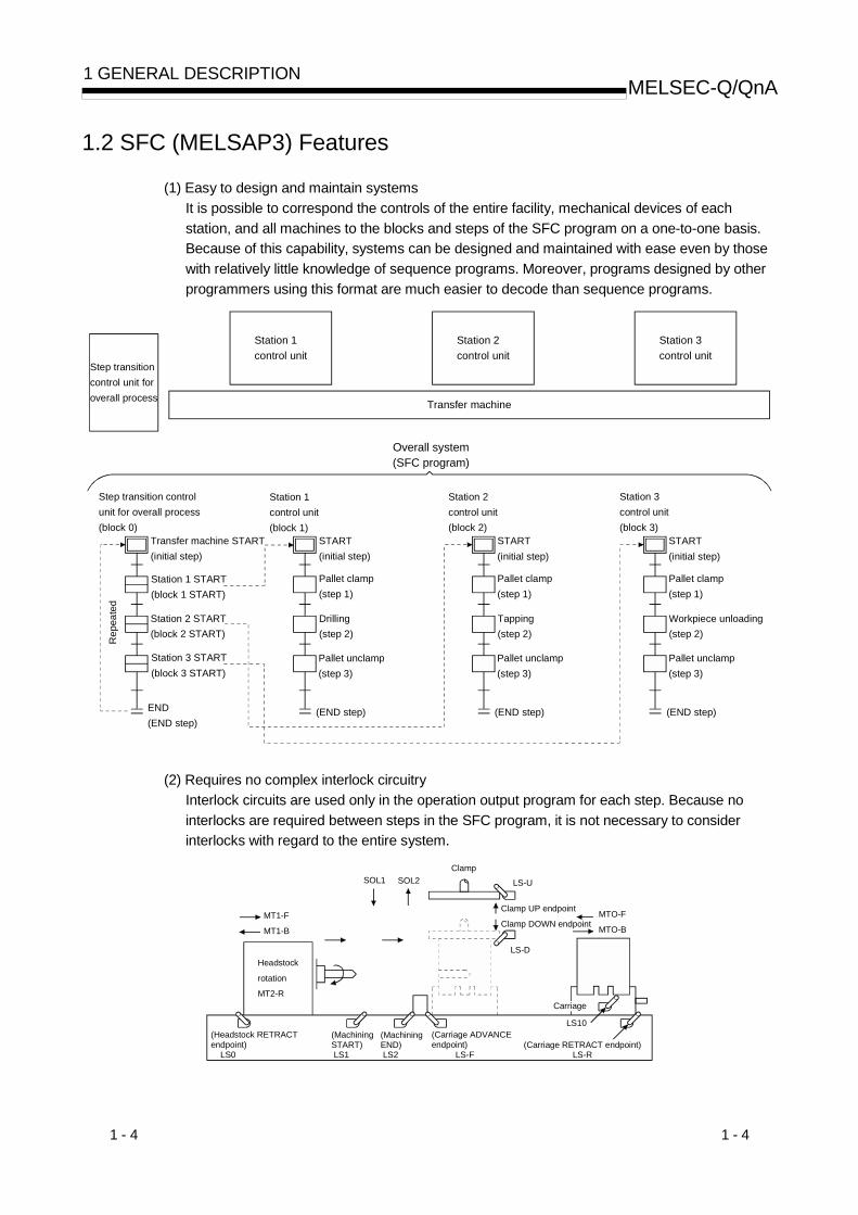
(1) Easy to design and maintain systemsIt is possible to correspond the controls of the entire facility, mechanical devices of eachstation, and all machines to the blocks and steps of the SFC program on a one-to-one basis.Because of this capability, systems can be designed and maintained with ease even by thosewith relatively little knowledge of sequence programs. Moreover, programs designed by otherprogrammers using this format are much easier to decode than sequence programs.
Step transitioncontrol unit foroverall process
Station 1control unit
Station 2control unit
Station 3control unit
Transfer machine
Overall system(SFC program)
Step transition control unit for overall process(block 0)
Station 3control unit(block 3)
Station 1control unit(block 1)
Station 2control unit(block 2)
Transfer machine START(initial step)
END(END step)
Station 3 START(block 3 START)
Station 2 START(block 2 START)
Station 1 START(block 1 START)
START(initial step)
Pallet clamp(step 1)
Drilling(step 2)
Pallet unclamp(step 3)
(END step)
START(initial step)
START(initial step)
Pallet clamp(step 1)
Tapping(step 2)
Pallet unclamp(step 3)
(END step)
Pallet clamp(step 1)
Workpiece unloading(step 2)
Pallet unclamp(step 3)
(END step)
Rep
eate
d
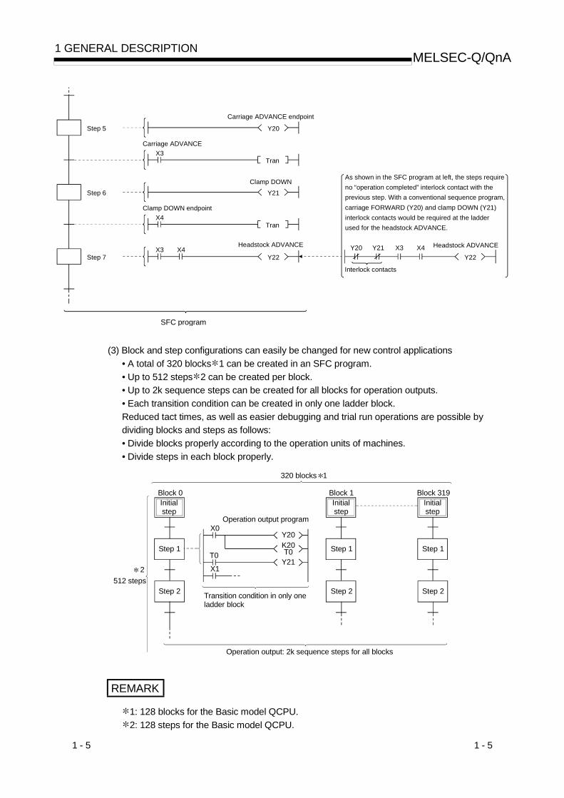
(2) Requires no complex interlock circuitryInterlock circuits are used only in the operation output program for each step. Because nointerlocks are required between steps in the SFC program, it is not necessary to considerinterlocks with regard to the entire system.
SOL1 SOL2Clamp
LS-U
Clamp UP endpoint
Clamp DOWN endpointMTO-F
MTO-BMT1-F
MT1-B
Headstock
rotation
MT2-R
LS10
LS-D
Carriage
(Headstock RETRACTendpoint) LS0
(MachiningSTART) LS1
(MachiningEND) LS2
(Carriage ADVANCEendpoint) LS-F
(Carriage RETRACT endpoint)LS-R
1 - 5 1 - 5
MELSEC-Q/QnA1 GENERAL DESCRIPTION
Y20
Carriage ADVANCE endpoint
Carriage ADVANCE X3
Tran
Y21Clamp DOWN
Step 6
Clamp DOWN endpointX4
Tran
Y22
Headstock ADVANCE
Step 7
Step 5
SFC program
As shown in the SFC program at left, the steps require no “operation completed” interlock contact with theprevious step. With a conventional sequence program, carriage FORWARD (Y20) and clamp DOWN (Y21) interlock contacts would be required at the ladderused for the headstock ADVANCE.
Y20
Interlock contacts
Y22
Headstock ADVANCEY21 X3 X4X3 X4
(3) Block and step configurations can easily be changed for new control applications• A total of 320 blocks 1 can be created in an SFC program.• Up to 512 steps 2 can be created per block.• Up to 2k sequence steps can be created for all blocks for operation outputs.• Each transition condition can be created in only one ladder block.Reduced tact times, as well as easier debugging and trial run operations are possible bydividing blocks and steps as follows:• Divide blocks properly according to the operation units of machines.• Divide steps in each block properly.
320 blocks 1
Initialstep
Step 1
Block 0 Block 1 Block 319
Transition condition in only one ladder block
512 steps
Operation output programX0
Y20
T0T0Y21
X1
K20
Step 2
2
Operation output: 2k sequence steps for all blocks
Initialstep
Step 1
Step 2
Initialstep
Step 1
Step 2
REMARK
1: 128 blocks for the Basic model QCPU.2: 128 steps for the Basic model QCPU.

1 - 6 1 - 6
MELSEC-Q/QnA1 GENERAL DESCRIPTION
(4) Creation of multiple initial steps is possibleMultiple processes can easily be executed and combined. Initial steps are linked using a“selection coupling” format.When multiple initial steps (S0 to S3) are active, the step where the transition condition (t4 tot7) immediately prior to the selected coupling is satisfied becomes inactive, and a transition tothe next step occurs. Moreover, when the transition condition immediately prior to an activestep is satisfied, the next step is executed in accordance with the parameter settings.
: The Basic model QCPU cannot be selected in the parameter.It operates in the default "Transfer" mode.
• Wait ............. Transition to the next step occurs after waiting for the next step to becomeinactive.
• Transfer....... Transition to the next step occurs even if the next step is active. (Default)• Pause.......... An error occurs if the next step is active.
S8
S4
t4
S0
t0
S7
t7
S3
t3
S6
t6
S2
t2
S5
t5
S1
t1
REMARK
Linked steps can also be changed at each initial step.
S6
S3
t3
S0
t0
S5
t5
S2
t2
S4
t4
S1
t1
S7
t6

1 - 7 1 - 7
MELSEC-Q/QnA1 GENERAL DESCRIPTION
(5) Program design is easy due to a wealth of step attributesA variety of step attributes can be assigned to each step. Used singly for a given controloperation, or in combination, these attributes greatly simplify program design procedures.• Types of HOLD steps, and their operations
1) Coil HOLD step ( SC )X0
Y10
X0
Y10
Step which is active due totransition condition beingsatisfied
(Transition condition satisfied)
• After a transition, operation outputprocessing continues (is maintained),and the coil output status at the timewhen the transition condition issatisfied is maintained regardless ofthe ON/OFF status of the interlockcondition (X0).
• Transition will not occur even if thetransition condition is satisfied again.
• Convenient for maintaining an outputuntil the block in question is completed(hydraulic motor output, passconfirmation signal, etc.).
2) Operation HOLD step (no transition check) ( SE )X0
Y10
X0
Y10
Step which is active due totransition condition beingsatisfied
• Even after a transition, operationoutput processing continues (ismaintained), and when the interlockcondition (X0) turns ON/OFF, the coiloutput (Y10) also turns ON/OFF.
• Transition will not occur if the transitioncondition is satisfied again.
• Convenient for repeating the sameoperation (cylinder advance/retract,etc.) while the relevant block is active.
3) Operation HOLD step (with transition check) ( ST )
MO
X0Y10
X1
Tran
PLS M0
(Transition executed)
Step which is active duethe previous transitioncondition being satisfied
• Even after a transition, operation outputprocessing continues (is maintained),and when the interlock condition (X0)turns ON/OFF, the coil output (Y10) alsoturns ON/OFF.
• When the transition condition is againsatisfied, the transition is executed, andthe next step is activated.
• Operation output processing is executedat the reactivated next step. When thetransition condition is satisfied, transitionoccurs, and the step is deactivated.
• Convenient for outputs where there is aninterlock with the next operation, forexample where machining is started oncompletion of a repeated operation(workpiece transport, etc.).

1 - 8 1 - 8
MELSEC-Q/QnA1 GENERAL DESCRIPTION
• Reset step ( R n)
R n When the reset step isactivated, a designatedstep will become inactive
• When a HOLD status becomesunnecessary for machine control, or onselective branching to a manual ladderoccurs after an error detection, etc., areset request can be designated for theHOLD step, deactivating the step inquestion.
• Types of block START steps, and their operations1) Block START step (with END check) ( m)
m
m
• In the same manner as for a subroutineCALL-RET, a START source blocktransition will not occur until the end ofthe START destination block is reached.
• Convenient for starting the same blockseveral times, or to use several blockstogether, etc.
• A convenient way to return to theSTART source block and proceed to thenext process block when a givenprocess is completed in a processingline, for example.
2) Block START step (Without END check) ( m)m
m
X0Tran
• Even if the START destination block isactive, a START source block transitionoccurs when the transition conditionassociated with the block START step issatisfied.At this time, the processing of theSTART destination block will becontinued unchanged until the end stepis reached.
• By starting another block at a given step,the START destination block can becontrolled independently andasynchronously with the START sourceblock until processing of the currentblock is completed.

1 - 9 1 - 9
MELSEC-Q/QnA1 GENERAL DESCRIPTION
(6) A given function can be controlled in a variety of ways according to the application in questionBlock functions such as START, END, temporary stop, restart, and forced activation andending of specified steps can be controlled by SFC diagram symbols, SFC control instructions,or by SFC information registers.• Control by SFC diagram symbols
................. Convenient for control of automatic operations with easy sequential control.• Control by SFC instructions
................. Enables requests from program files other than the SFC, and is convenient forerror processing, for example after emergency stops, and interrupt control.
• Control by SFC information devices................. Enables control of SFC peripheral devices, and is convenient for partial
operations such as debugging or trial runs.
Functions which can be controlled by these 3 methods are shown below.
Control MethodFunction
SFC Diagram SFC ControlInstructions SFC Information Registers
Block START(with END wait) m
Block START(without END wait) m SET BLm Block START/END bit ON
Block END RST BLm Block START/END bit OFF
Block STOP PAUSE BLm Block STOP/RESTART bit ON
Restart stopped block RSTART BLm Block STOP/RESTART bit OFFForced stepactivation
SET SnSCHG Kn
Forced step END R n RST SnSCHG Kn
1) In cases where the same function can be executed by a number of methods, the first controlmethod which has been designated by the request output to the block or step in questionwill be the effective control method.
2) Functions controlled by a given control method can be canceled by another control method.Example: For block STARTThe active block started by the SFC diagram ( m) can be forcibly ended by executingthe SFC control instruction (RST BLm) before the END step ( ) or by turning OFF theblock START/END bit of the SFC information devices.
(7) A sophisticated edit function simplifies editing operationsA same-screen SFC diagram, operation output, and transition condition ladder display featuresa zoom function which can split the screen 4 ways (right/left/upper/lower) to simplify programcut-and-paste operations. Moreover, advanced program edit functions such as the SFCdiagram or device search function, etc., make program creation and editing operations quickand easy.

1 - 10 1 - 10
MELSEC-Q/QnA1 GENERAL DESCRIPTION
(8) Displays with comments for easy understandingComments can be entered at each step and transition condition item.Up to 32 characters can be entered.
Y10
Y20
1234567
S0
Ready,waitingfor start
Mix BSN11
Mix A SN22
SD3 Wait ateSD4Wrt <Ins>Ld Step
Wait ste1 2 [Mix A ]
0
2
I 0
(9) An automatic scrolling functions enables quick identification of mechanical system troublespotsActive (execution) blocks and steps, as well as the execution of operation output/transitioncondition ladders can be monitored by a peripheral device (with automatic scrolling function).This monitor function enables even those with little knowledge of sequence programs to easilyidentify trouble spots.

1 - 11 1 - 11
MELSEC-Q/QnA1 GENERAL DESCRIPTION
(10) Convenient trace function (when using GPPQ with QnACPU)Blocks can be synchronized and traced, enabling the user to check the operation timing ofmultiple blocks.Moreover, the trace results display screen can be switched to display the trace result detailsfor each block.
Block
12
-51 15 15
222015
4 64
Active step Nos.are displayed (fromsmallest No.) foreach block
0
[Trace Results Display]
0 5
Active step No.display
[Trace Results Display]
PgUp:Prev PgDn:Next Esc:Close
Block No. Where traceoccurred
1
2117220-32400819402819403204404204
6
58
5Block
-5 0

2 - 1 2 - 1
MELSEC-Q/QnA2 SYSTEM CONFIGURATION
2. SYSTEM CONFIGURATION(1) Applicable CPU models
MELSAP3 (SFC program) can be run by the following CPU models.
CPU Type Model Name Restriction
Basic model QCPU Q00JCPU, Q00CPU, Q01CPU
Product whose firstfive digits of serial No.are 04122 or later iscompatible.
High Performance model QCPU Q02CPU, Q02HCPU, Q06HCPU, Q12HCPU, Q25HCPUProcess CPU Q12PHCPU, Q25PHCPU
QnACPUQ2ASCPU, Q2ASCPU-S1, Q2ASHCPU, Q2ASHCPU-S1Q2ACPU, Q3ACPU, Q4ACPU, Q4ARCPU
(2) Peripheral devices for the SFC programSFC program creation, editing, and monitoring operations are conducted at the followingperipheral devices.
Compatible CPUPeripheralDeviceModelName
SoftwarePackage Model
Name forPersonalComputer
Basic modelQCPU
High Performancemodel QCPU
ProcessCPU QnACPU
Remarks
SW3D5C/F-GPPWSW4D5C-
GPPW or laterGX DeveloperVersion 7.10L
(SW7D5C-GPPW) or later
Personalcomputer
(Windows®
compatible)GX Developer
Version 8(SW8D5C-
GPPW) or laterPC/AT
compatiblepersonalcomputer
SW2IVD-GPPQ
PC9801 SW2NX-GPPQ
Q6PU
• Display is providedin list representationwhere an SFCdiagram has beenreplaced byinstructions.
• SFC diagramscannot be created oredited.Only creation andcorrection of laddersassociated withoperation outputsand transitionconditions areallowed.
: Usable, : Unusable
2

2 - 2 2 - 2
MELSEC-Q/QnA2 SYSTEM CONFIGURATION
MEMO
2

3 - 1 3 - 1
MELSEC-Q/QnA3 SPECIFICATIONS
3. SPECIFICATIONSThis chapter explains the performance specifications of SFC programs.
3.1 Performance Specifications Related to SFC Programs
3.1.1 Performance specifications of Basic model QCPU
(1) Table 3.1 indicates the performance specifications related to an SFC program.
Table 3.1 Performance Specifications Related to SFC ProgramItem Q00JCPU Q00CPU Q01CPU
Capacity Max. 8k steps Max. 8k steps Max. 14k stepsNumber of files Scannable SFC program: 1 file *1Number of blocks Max. 128 blocksNumber of SFC steps Max. 1024 steps for all blocks, max. 128 steps for one blockNumber of branches Max. 32
Number of concurrently active steps Max. 1024 steps for all blocksMax. 128 steps for one block (including HOLD steps)
Number of operation output sequencesteps
Max. 2k steps for all blocksNo restriction on one step
SFC program
Number of transition condition sequencesteps One ladder block only
*1: SFC program for program management (Section 5.2.3) cannot be created.
REMARK
The step transition watchdog timer, STEP-RUN operation and step trace functions are notavailable.
3

3 - 2 3 - 2
MELSEC-Q/QnA3 SPECIFICATIONS
(2) Precautions for creating SFC program
(a) Only one SFC program can be created.The created SFC program is a "scan execution type program".
(b) The Basic model QCPU allows creation of a total of two program files: one SFC programand one sequence program.(Two sequence programs or two SFC programs cannot be created.)
Sequence program
(MAIN.QPG)
SFC program(MAIN-SFC.QPG)
Scan execution type program
(c) The created sequence program and SFC program have the following file names. (The filenames cannot be changed.)• Sequence program: MAIN.QPG• SFC program: MAIN-SFC.QPG
(d) The SFC program and sequence program are processed in order of "sequence program"and "SFC program".(The processing order of the SFC program and sequence program cannot be changed.)
3
3 - 3 3 - 3
MELSEC-Q/QnA3 SPECIFICATIONS
3.1.2 Performance specifications of High Performance model QCPU andProcess CPU
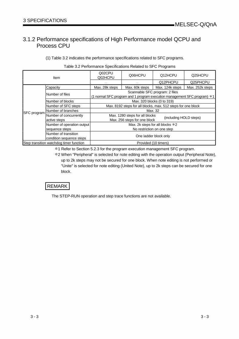
(1) Table 3.2 indicates the performance specifications related to SFC programs.
Table 3.2 Performance Specifications Related to SFC ProgramsQ02CPU
Q02HCPU Q06HCPU Q12HCPU Q25HCPUItemQ12PHCPU Q25PHCPU
Capacity Max. 28k steps Max. 60k steps Max. 124k steps Max. 252k steps
Number of files Scannable SFC program: 2 files(1 normal SFC program and 1 program execution management SFC program) 1
Number of blocks Max. 320 blocks (0 to 319)Number of SFC steps Max. 8192 steps for all blocks, max. 512 steps for one blockNumber of branches Max. 32Number of concurrentlyactive steps
Max. 1280 steps for all blocksMax. 256 steps for one block (including HOLD steps)
Number of operation outputsequence steps
Max. 2k steps for all blocks 2No restriction on one step
SFC program
Number of transitioncondition sequence steps One ladder block only
Step transition watchdog timer function Provided (10 timers)1 Refer to Section 5.2.3 for the program execution management SFC program.2 When "Peripheral" is selected for note editing with the operation output (Peripheral Note),
up to 2k steps may not be secured for one block. When note editing is not performed or"Unite" is selected for note editing (United Note), up to 2k steps can be secured for oneblock.
REMARK
The STEP-RUN operation and step trace functions are not available.

3 - 4 3 - 4
MELSEC-Q/QnA3 SPECIFICATIONS
(2) Precautions for creating SFC program
(a) The SFC programs that can be created are "scan execution type program" and"standby type program".
(b) Two SFC programs (one normal SFC program and one program executionmanagement SFC program) can be set as a scan execution type program.
(c) More than one SFC program can be set as a standby type program.
(d) The standby type SFC program is executed in the following procedure.• The currently executed scan execution type program is switched to the standby typeprogram.
• The standby type program to be executed is switched to the scan execution typeprogram.
Initial executiontype program
Scan execution type program
More than one program can be set.(SFC program cannot be set.)
More than one program can be set.(Two SFC programs, normal and program execution management, can be set.)
Standby type program
More than one program can be set.
Low-speed execution type program
More than one program can be set.
(SFC program cannot be set.)
Fixed-cycle execution type program
The maximum number of program files changes depending on the CPU module type.For details, refer to the user's manual (function explanation, program fundamentals) of the used CPU module.
(More than one SFC program can be set for both normal and program execution management programs.)
REMARK
Use the PSCAN or POFF instruction to switch the execution type of the program.For details of the PSCAN and POFF instructions, refer to the QCPU (Q mode)/QnACPUProgramming Manual (Common Instructions)

3 - 5 3 - 5
MELSEC-Q/QnA3 SPECIFICATIONS
3.1.3 Performance specifications of QnACPU
(1) Table 3.3 indicates the performance specifications related to SFC programs.
Table 3.3 Performance Specifications Related to SFC Programs
ItemQ2ACPU
Q2ASCPUQ2ASHCPU
Q2ACPU-S1Q2ASCPU-S1
Q2ASHCPU-S1Q3ACPU Q4ACPU
Q4ARCPU
Capacity Max. 28k steps Max. 60k steps Max. 92k steps Max. 124k steps
Number of filesScannable SFC program: 2 files
(1 normal SFC program and 1 program execution management SFCprogram) 1
Number of blocks Max. 320 blocks (0 to 319)Number of SFC steps Max. 8192 steps for all blocks, max. 512 steps for one blockNumber of branches Max. 32Number of concurrentlyactive steps
Max. 1280 steps for all blocksMax. 256 steps for one block (including HOLD steps)
Number of operationoutput sequence steps
Max. 2k steps for all blocks 3No restriction on one step
SFC program
Number of transitioncondition sequencesteps
One ladder block only
All-block break Batch break setting for all blocksDesignated block break Up to 64 blocks can be set for the designated blocks.Designated step break Up to 64 points can be set for the designated steps.Break
Number of cycles 1 to 255 timesDesignated blockcontinue 1 block is set for the designated block.
Designated stepcontinue 1 point is set for the designated step.Continue
Continue fromdesignated step 1 point is set for the designated step.
Forced block execution 1 block is set for the designated block.Forced 1 step executionfor designated step 1 point is set for the designated step.
Forced block end 1 block is set for the designated block.
STEP-RUNoperationfunction
Forcedexecution
Forced step end 1 point is set for the designated step.Trace memory capacity Max. 48k bytes for all blocks, 1 to 48k bytes for one block (1k byte units)Trace memory capacityafter trigger 128 bytes to capacity setting of each block
Block designation Max. 12 blocksTrigger step 1 step per block
Step trace function 2(Memory card required)
Execution condition Per designated time or per scanStep transition watchdog timer function Provided (10 timers)
1 Refer to Section 5.2.3 for the program execution management SFC program.2 This function can be executed only when the software package for personal computer is
SW2IVD-GPPW/SW2NX-GPPW.3 When "Peripheral" is selected for note editing with the operation output (Peripheral Note),
up to 2k steps may not be secured for one block. When note editing is not performed or"Unite" is selected for note editing (United Note), up to 2k steps can be secured for oneblock.

3 - 6 3 - 6
MELSEC-Q/QnA3 SPECIFICATIONS
(2) Precautions for creating SFC programs
(a) The SFC programs that can be created are "scan execution type program" and"standby type program".
(b) Two SFC programs (one normal SFC program and one program executionmanagement SFC program) can be set as a scan execution type program.
(c) More than one SFC program can be set as a standby type program.
(d) The standby type SFC program is executed in the following procedure.• The currently executed scan execution type program is switched to the standby typeprogram.
• The standby type program to be executed is switched to the scan execution typeprogram.
Initial executiontype program
Scan execution type program
More than one program can be set.(SFC program cannot be set.)
More than one program can be set.(Two SFC programs, normal and program execution management, can be set.)
Standby type program
Low-speed execution type program
More than one program can be set.
(SFC program cannot be set.)
Fixed-cycle execution type program
The maximum number of program files changes depending on the CPU module type.For details, refer to the user's manual (details) of the used CPU module.
More than one program can be set.(More than one SFC program canbe set for both normal and programexecution management programs.)
REMARK
Use the PSCAN or POFF instruction to switch the execution type of the program.For details of the PSCAN and POFF instructions, refer to the QCPU (Q mode)/QnACPUProgramming Manual (Common Instructions).
3 - 7 3 - 7
MELSEC-Q/QnA3 SPECIFICATIONS
3.2 Device List
3.2.1 Device list of Basic model QCPU
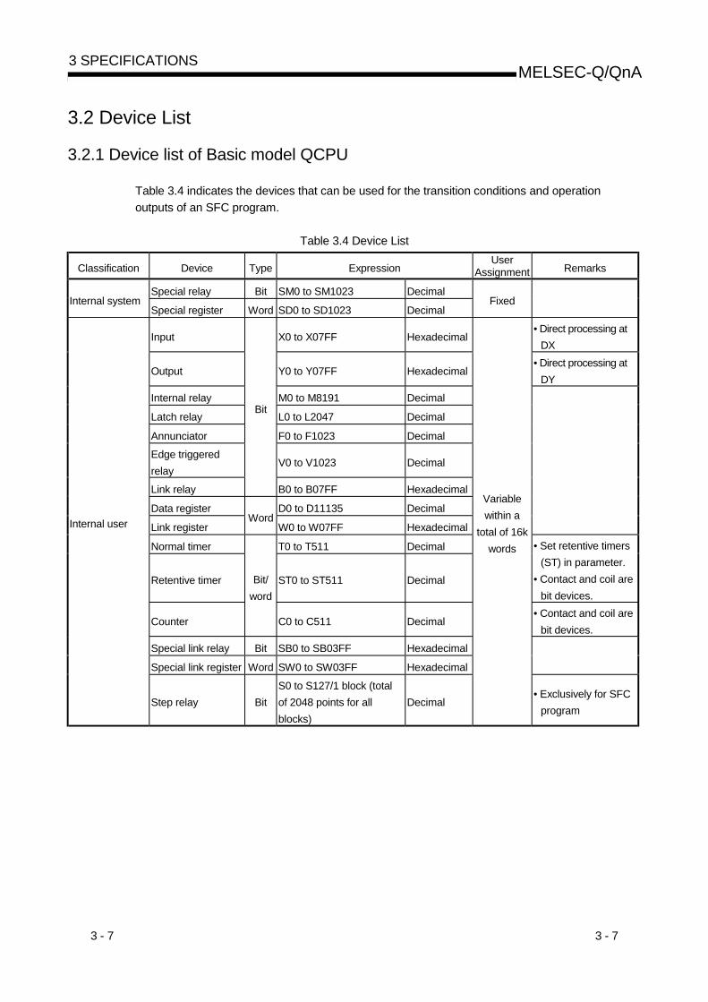
Table 3.4 indicates the devices that can be used for the transition conditions and operationoutputs of an SFC program.
Table 3.4 Device List
Classification Device Type ExpressionUser
Assignment Remarks
Special relay Bit SM0 to SM1023 DecimalInternal system
Special register Word SD0 to SD1023 DecimalFixed
Input X0 to X07FF Hexadecimal• Direct processing at
DX
Output Y0 to Y07FF Hexadecimal• Direct processing at
DY
Internal relay M0 to M8191 Decimal
Latch relay L0 to L2047 Decimal
Annunciator F0 to F1023 Decimal
Edge triggeredrelay
V0 to V1023 Decimal
Link relay
Bit
B0 to B07FF Hexadecimal
Data register D0 to D11135 Decimal
Link registerWord
W0 to W07FF Hexadecimal
Normal timer T0 to T511 Decimal
Retentive timer ST0 to ST511 Decimal
• Set retentive timers(ST) in parameter.
• Contact and coil arebit devices.
Counter
Bit/word
C0 to C511 Decimal• Contact and coil are
bit devices.
Special link relay Bit SB0 to SB03FF Hexadecimal
Special link register Word SW0 to SW03FF Hexadecimal
Internal user
Step relay BitS0 to S127/1 block (totalof 2048 points for allblocks)
Decimal
Variablewithin a
total of 16kwords
• Exclusively for SFCprogram

3 - 8 3 - 8
MELSEC-Q/QnA3 SPECIFICATIONS
Classification Device Type ExpressionUser
Assignment Remarks
Link input J \ X0 to J \ X01FFF Hexadecimal
Link output J \ Y0 to J \ Y01FFF Hexadecimal
Link relay J \ B0 to J \ B03FFF Hexadecimal
Link special relay
Bit
J \ SB0 to J \ SB01FF Hexadecimal
Link register J \ W0 to J \ W03FFF Hexadecimal
Link direct(MELSECNET/H)
Link special registerWord
J \ SW0 to J \ SW01FF Hexadecimal
Fixed
• Devices on the leftexist in each linkmodule.
• indicates thenetwork No., any of1 to 239 and 254.
Intelligentfunction moduledirect
Buffer register Word J \ G0 to J \ G65535 Decimal
Fixed(depending
onintelligentfunctionmodule)
• Exist in eachintelligent functionmodule.
• indicates the I/ONo. /16, andchanges dependingon the model asindicated below.Q00JCPU: 0 to 0FQ00CPU, Q01CPU:0 to 03F
Index register Index register Word Z0 to Z9 Decimal Fixed
R0 to R32767 Decimal• When block
switching is usedFile register File register 1 Word
ZR0 to ZR65535 DecimalFixed
• When serial No. isused
Pointer Pointer P0 to P299 Decimal Fixed
SFC block Bit BL0 to BL127 Decimal• Exclusively for SFC
program
Network No. J1 to J239, J254 DecimalOther
I/O NOQ00JCPU: U0 to U0FQ00CPU, Q01CPU:U0 to U03F
Hexadecimal
Fixed
Decimal constant K-2147483648 to K2147483647
Hexadecimalconstant
H0 to HFFFFFFFF
Real numberconstant
E 1.17550-38 to E 3.40282+38Constant
Character stringconstant
"ABC123", etc.
1: Can be used for the Q00CPU and Q01CPU only.

3 - 9 3 - 9
MELSEC-Q/QnA3 SPECIFICATIONS
3.2.2 Device list of High Performance model QCPU, Process CPU andQnACPU
Table 3.5 indicates the devices that can be used for the transition conditions and operationoutputs of SFC programs.
Table 3.5 Device List
Classification Device Type ExpressionUser
Assignment Remarks
Special relay Bit SM0 to SM2047 DecimalInternal system
Special register Word SD0 to SD2047 DecimalFixed
Input X0 to X01FFF Hexadecimal• Direct processing at
DX
Output Y0 to Y01FFF Hexadecimal• Direct processing at
DY
Internal relay M0 to M8191 Decimal
Latch relay L0 to L8191 Decimal
Annunciator F0 to F2047 Decimal
Edge triggeredrelay
V0 to V2047 Decimal
Link relay
Bit
B0 to B01FFF Hexadecimal
Data register D0 to D12287 Decimal
Link registerWord
W0 to W01FFF Hexadecimal
Normal timer T0 to T2047 Decimal
Retentive timer ST0 to ST2047 Decimal
• Set retentive timers(ST) in parameter.
• Contact and coil arebit devices.
Counter
Bit/word
C0 to C1023 Decimal• Contact and coil are
bit devices.
Special link relay Bit SB0 to SB07FF Hexadecimal
Special link register Word SW0 to SW07FF Hexadecimal
Internal user
Step relay BitS0 to S511/1 block (total of8192 points for all blocks)
Decimal
Variablewithin a total
of 28.75kwords
• Exclusively for SFCprogram

3 - 10 3 - 10
MELSEC-Q/QnA3 SPECIFICATIONS
Classification Device Type ExpressionUser
Assignment Remarks
Link input J \ X0 to J \ X01FFF Hexadecimal
Link output J \ Y0 to J \ Y01FFF Hexadecimal
Link relay J \ B0 to J \ B03FFF Hexadecimal
Link special relay
Bit
J \ SB0 to J \ SB07FF Hexadecimal
Link register J \ W0 to J \ W03FFF Hexadecimal
Link direct(MELSECNET/10,MELSECNET/H)
Link specialregister
WordJ \ SW0 to J \ SW07FF Hexadecimal
Fixed
• Devices on the leftexist in each linkmodule.
• indicates thenetwork No., any of1 to 239 and 254.
Special moduledirect
Buffer register Word J \ G0 to J \ G65535 Decimal
Fixed(depending
onintelligentfunctionmodule)
• Exist in each specialfunctionmodule/intelligentfunction module.
• indicates the I/ONo. /16, any of 0 to0FF.
Index register Index register Word Z0 to Z15 Decimal Fixed
R0 to R32767 Decimal• When block
switching is usedFile register File register Word
ZR0 to ZR1042431 DecimalFixed
• When serial No. isused
Pointer Pointer P0 to P8191 Decimal Fixed
SFC block BL0 to BL319 Decimal
SFC transitiondevice
Bit TR0 to TR511/block(Total of 8192 points for allblocks)
Decimal• Exclusively for SFC
program
Network No. J1 to J239, J254 Decimal
Other
I/O NO U0 to UOFF Hexadecimal
Fixed
Decimal constant K-2147483648 to K2147483647
Hexadecimalconstant
H0 to H0FFFFFFFF
Real numberconstant
E 1.17550-38 to E 3.40282+38Constant
Character stringconstant
"ABC123", etc.

3 - 11 3 - 11
MELSEC-Q/QnA3 SPECIFICATIONS
3.3 Processing Time for SFC Program
The time required to process the SFC program is discussed below.
(1) Method for calculating the SFC program processing timeCalculate the SFC program processing time with the following expression
SFC program processing time (A) + (B) + (C)
(a) "(A): Processing time of operation outputs in all blocks"Indicates the total sum of the processing times of the instructions used for the operationoutputs of all steps that are active.For the processing times of the instructions, refer to the QCPU (Q mode)/QnACPUProgramming Manual (Common Instructions).
(b) "(B): Processing time of all transition conditions"Indicates the total sum of the processing times of the instructions used for the transitionconditions associated with all steps that are active.For the processing times of the instructions, refer to the QCPU (Q mode)/QnACPUProgramming Manual (Common Instructions).
(c) "(C)" SFC system processing time"Calculate the SFC system processing time with the following expression.
SFC system processing time (a) + (b) + (c) + (d) + (e) + (f) + (g)
Processing Time Calculation of Processing Time (Unit: µs)(a) Active block
processingtime
(Active block processing time) (active block processing time coefficient) (number of active blocks)• Active block processing time: System processing time required to execute active blocks• Number of active blocks: Number of blocks that are active
(b) Inactive blockprocessingtime
(Inactive block processing time) (inactive block processing time coefficient) (number of inactive blocks)• Inactive block processing time: System processing time required to execute inactive blocks• Number of inactive blocks: Number of blocks that are inactive
(c) Nonexistentblockprocessingtime
(Nonexistent block processing time) (nonexistent block processing time coefficient) (number ofnonexistent blocks)
• Nonexistent block processing time: System processing time required to execute blocks that have notbeen created
• Number of nonexistent blocks: Number of blocks where programs have not been created within thenumber of blocks set in the parameter
(d) Active stepprocessingtime
(Active step processing time) (active step processing time coefficient) (number of active steps)• Active step processing time: Time required to execute active steps• Number of active steps: Number of steps that are active in all blocks
(e) Activetransitionprocessingtime
(Active transition processing time) (active transition processing time coefficient) (number of activetransitions)
• Active transition processing time: System processing time required to execute active transitions• Number of active transitions: Number of transition conditions associated with all steps that are active
in all blocks(f) Transition
condition-satisfied stepprocessingtime
(Transition condition-satisfied step processing time) (transition condition-satisfied step processingtime coefficient) (number of transition condition-satisfied steps)
• Transition condition-satisfied step processing time: Time required to perform OFF execution of activesteps
• Number of transition condition-satisfied steps: Number of steps where operation outputs are turnedOFF since transition conditions were satisfied in all blocks
(g) SFC endprocessingtime
(SFC end processing time) (SFC end processing time)• SFC end processing time: System processing time required to perform the end processing of SFC
program.
3 - 12 3 - 12
MELSEC-Q/QnA3 SPECIFICATIONS
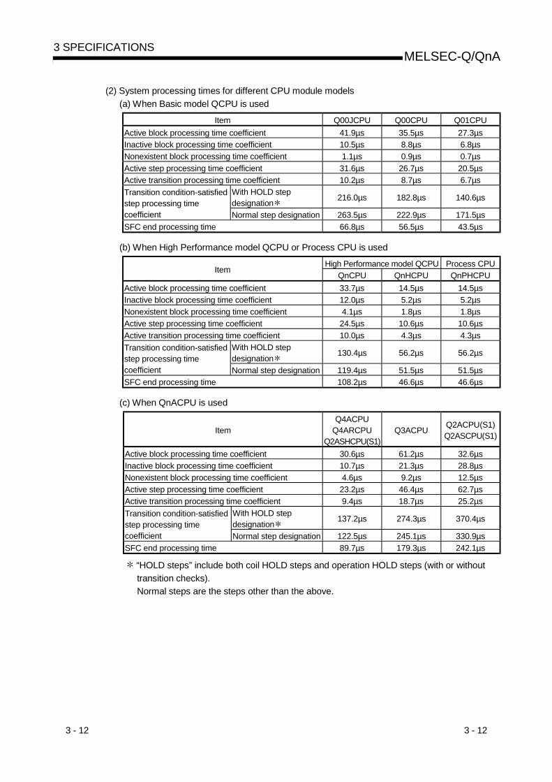
(2) System processing times for different CPU module models(a) When Basic model QCPU is used
Item Q00JCPU Q00CPU Q01CPUActive block processing time coefficient 41.9µs 35.5µs 27.3µsInactive block processing time coefficient 10.5µs 8.8µs 6.8µsNonexistent block processing time coefficient 1.1µs 0.9µs 0.7µsActive step processing time coefficient 31.6µs 26.7µs 20.5µsActive transition processing time coefficient 10.2µs 8.7µs 6.7µs
With HOLD stepdesignation 216.0µs 182.8µs 140.6µsTransition condition-satisfied
step processing timecoefficient Normal step designation 263.5µs 222.9µs 171.5µsSFC end processing time 66.8µs 56.5µs 43.5µs
(b) When High Performance model QCPU or Process CPU is used
High Performance model QCPU Process CPUItem
QnCPU QnHCPU QnPHCPUActive block processing time coefficient 33.7µs 14.5µs 14.5µsInactive block processing time coefficient 12.0µs 5.2µs 5.2µsNonexistent block processing time coefficient 4.1µs 1.8µs 1.8µsActive step processing time coefficient 24.5µs 10.6µs 10.6µsActive transition processing time coefficient 10.0µs 4.3µs 4.3µs
With HOLD stepdesignation 130.4µs 56.2µs 56.2µsTransition condition-satisfied
step processing timecoefficient Normal step designation 119.4µs 51.5µs 51.5µsSFC end processing time 108.2µs 46.6µs 46.6µs
(c) When QnACPU is used
ItemQ4ACPU
Q4ARCPUQ2ASHCPU(S1)
Q3ACPU Q2ACPU(S1)Q2ASCPU(S1)
Active block processing time coefficient 30.6µs 61.2µs 32.6µsInactive block processing time coefficient 10.7µs 21.3µs 28.8µsNonexistent block processing time coefficient 4.6µs 9.2µs 12.5µsActive step processing time coefficient 23.2µs 46.4µs 62.7µsActive transition processing time coefficient 9.4µs 18.7µs 25.2µs
With HOLD stepdesignation 137.2µs 274.3µs 370.4µsTransition condition-satisfied
step processing timecoefficient Normal step designation 122.5µs 245.1µs 330.9µsSFC end processing time 89.7µs 179.3µs 242.1µs
“HOLD steps” include both coil HOLD steps and operation HOLD steps (with or withouttransition checks).Normal steps are the steps other than the above.

3 - 13 3 - 13
MELSEC-Q/QnA3 SPECIFICATIONS
[SFC system processing time calculation example]Using the Q25HCPU as an example, the processing time for the SFC system is calculatedas shown below, given the following conditions.
• Designated at initial START• Number of active blocks: 30 (active blocks at SFC program)• Number of inactive blocks: 70 (inactive blocks at SFC program)• Number of nonexistent blocks: 50 (number of blocks between 0 and the max. created
block No. which have no SFC program)• Number of active steps: 60 (active steps within active blocks)• Active step transition conditions: 60• Steps with satisfied transition conditions: 10
(active steps (no HOLD steps) with satisfied transition conditions)
SFC system process time =(14.5 × 30) + (5.2 × 70) + (1.8 × 50) + (10.6 × 60) + (4.3 × 60) + (56.2 × 10) + 46.6 = 2391.6 µs 2.40 ms
In this case, calculation using the equation shown above results in an SFC systemprocessing time of 2.40 ms.With the Q4ACPU, given the same conditions, the processing time would be 5.32 ms.The scan time is the total of the following times;SFC system processing time, main sequence program processing time, SFC active steptransition condition ladder processing time, and CPU END processing time.The scan time is the total of the following times:SFC system processing time, main sequence program processing time, processing time ofladder circuit having transition conditions associated with SFC's active steps, and CPUmodule's END processing time.The number of active steps, the number of transition conditions, and the number of stepswith satisfied transition conditions varies according to the conditions shown below.
• When transition condition is unsatisfied• When transition condition is satisfied (without continuous transition)• When transition condition is satisfied (with continuous transition)
The method for determining the number of the above items is illustrated in the SFC diagram below.
Step 1
Step 2
Step 3
Transition condition 1
Transitioncondition 2
Step 4
Transitioncondition 3
Step 5
Transitioncondition 4
Step 10
Transition condition 8
Step 6
Step 7
Transitioncondition 5
Step 8
Transitioncondition 6
Step 9
Transitioncondition 7

3 - 14 3 - 14
MELSEC-Q/QnA3 SPECIFICATIONS
The following table indicates the number of active steps, number of active transitions, and numberof transition condition-satisfied steps when Step 2 and Step 6 are active.
Whether TransitionConditions AreSatisfied or Not
Presence/Absenceof Continuous
Transition
Number of ActiveSteps
Number of ActiveTransitions
Number ofTransitionCondition-
Satisfied Steps
• Transition conditionsnot satisfied
2(Steps 2, 6)
2(Transition
conditions 2, 5)0
Absence2
(Steps 2, 6)
2(Transition
conditions 2, 5)
2(Steps 2, 6)• Transition conditions
2, 5 satisfied• Transition conditions
3, 6 not satisfied Presence4
(Steps 2, 3, 6, 7)
4(Transition
conditions 2, 3, 5, 6)
2(Steps 2, 6)
Absence2
(Steps 2, 6)
2(Transition
conditions 2, 5)
2(Steps 2, 6)
• Transition conditions2, 3, 5, 6 satisfied
Presence6
(Steps 2 to 4, 6 to 8)
6(Transition
conditions 2 to 7)
4(Steps 2, 3, 6, 7)
3 - 15 3 - 15
MELSEC-Q/QnA3 SPECIFICATIONS
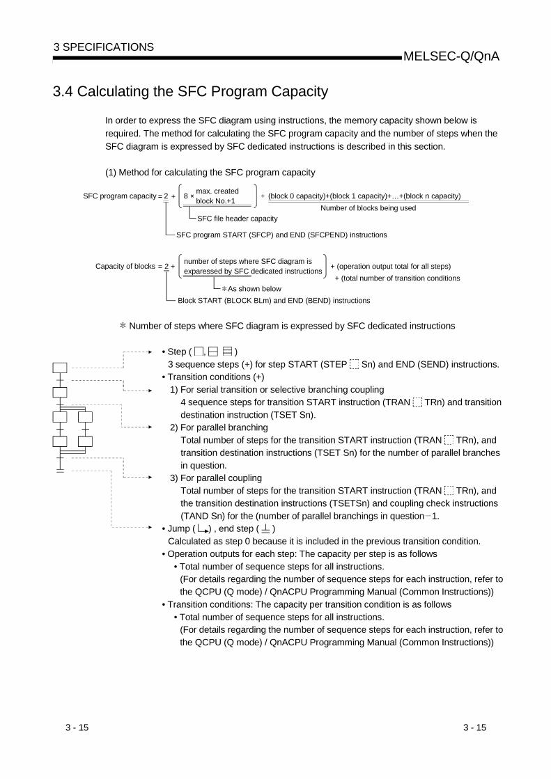
3.4 Calculating the SFC Program Capacity
In order to express the SFC diagram using instructions, the memory capacity shown below isrequired. The method for calculating the SFC program capacity and the number of steps when theSFC diagram is expressed by SFC dedicated instructions is described in this section.
(1) Method for calculating the SFC program capacity
max. createdblock No.+1SFC program capacity (block 0 capacity)+(block 1 capacity)+…+(block n capacity)
Number of blocks being usedSFC file header capacity
SFC program START (SFCP) and END (SFCPEND) instructions
number of steps where SFC diagram isexparessed by SFC dedicated instructions + (operation output total for all steps)
As shown belowBlock START (BLOCK BLm) and END (BEND) instructions
Capacity of blocks
2 8
2 +
+=
=
+
+ (total number of transition conditions
Number of steps where SFC diagram is expressed by SFC dedicated instructions
• Step ( , )3 sequence steps (+) for step START (STEP Sn) and END (SEND) instructions.
• Transition conditions (+)1) For serial transition or selective branching coupling
4 sequence steps for transition START instruction (TRAN TRn) and transitiondestination instruction (TSET Sn).
2) For parallel branchingTotal number of steps for the transition START instruction (TRAN TRn), andtransition destination instructions (TSET Sn) for the number of parallel branchesin question.
3) For parallel couplingTotal number of steps for the transition START instruction (TRAN TRn), andthe transition destination instructions (TSETSn) and coupling check instructions(TAND Sn) for the (number of parallel branchings in question 1.
• Jump ( ) , end step ( )Calculated as step 0 because it is included in the previous transition condition.
• Operation outputs for each step: The capacity per step is as follows• Total number of sequence steps for all instructions.
(For details regarding the number of sequence steps for each instruction, refer tothe QCPU (Q mode) / QnACPU Programming Manual (Common Instructions))
• Transition conditions: The capacity per transition condition is as follows• Total number of sequence steps for all instructions.
(For details regarding the number of sequence steps for each instruction, refer tothe QCPU (Q mode) / QnACPU Programming Manual (Common Instructions))

3 - 16 3 - 16
MELSEC-Q/QnA3 SPECIFICATIONS
(2) Number of steps required for expressing the SFC diagram as SFC dedicated instructionsThe following table shows the number of steps required for expressing the SFC diagram asSFC dedicated instructions.
Name LadderExpression
Number ofSteps Description Required Number of Steps
SFCP STARTinstruction [SFCP] 1 Indicates the SFC program
START 1 per program
SFCP END instruction [SFCPEND] 1 Indicates the SFC programEND 1 per program
Block STARTinstruction [BLOCK BLm] 1 Indicates the block START 1 per block
Block END instruction [BEND] 1 Indicates the block END 1 per block
Step STARTinstruction [STEP Si] 2
Indicates the step START(“ ” varies according to thestep attribute)
1 per step
Transition STARTinstruction [TRAN TRj] 2
Indicates the transitionSTART (“ ” variesaccording to the stepattribute)
1 per transition condition
Coupling checkinstruction [TAND Si] 2 “Coupling completed” check
occurs at parallel coupling“[Number of parallel couplings] - [1]”per parallel coupling
Transition designationinstruction [TSET Si] 2 Designates the transition
destination step
For serial transitions and selectiontransitions, 1 per transition condition;for parallel branching transitions, thenumber of steps is the same as thenumber of parallel couplings
Step END instruction [SEND] 1 Indicates the step / transitionEND 1 per step

4 - 1 4 - 1
MELSEC-Q/QnA4 SFC PROGRAM CONFIGURATION
4. SFC PROGRAM CONFIGURATIONThis chapter explains the SFC program symbols, SFC control instructions and SFC informationdevices that comprise an SFC program.
(1) As shown below, an SFC program consists of an initial step, transition conditions, intermediatesteps, and an END step. The data beginning from the initial step and ending at the END step isreferred to as a block.
Initial step
Transition conditionTransition condition 0(t0)
Step
Transition conditionTransition condition 1(t1)
Step 1(S1)
Step
End step
Step 2(S2)
Block
Step 0(S0)
(2) An SFC program starts at an initial step, executes a step following a transition condition in dueorder every time that transition condition is satisfied, and ends a series of operations at an endstep.
(a) When the SFC program is started, the initial step is executed first.While the initial step is being executed, whether the transition condition following the initialstep (transition condition 0 (t0) in the figure) has been satisfied or not is checked.
(b) Only the initial step is executed until transition condition 0 (t0) is satisfied.When transition condition 0 (t0) is satisfied, the execution of the initial step is stopped, andthe step following the initial step (step 1 (S1) in the figure) is executed.While step 1 (S1) is being executed, whether the transition condition following step 1(transition condition 1 (t1) in the figure) has been satisfied or not is checked.
(c) When transition condition 1 (t1) is satisfied, the execution of step 1 (S1) is stopped, and thenext step (step 2 (S2) in the figure) is executed.
(d) Every time the transition condition is satisfied in order, the next step is executed, and theblock ends when the end step is executed.
4

4 - 2 4 - 2
MELSEC-Q/QnA4 SFC PROGRAM CONFIGURATION
4.1 List of SFC Diagram Symbols
The symbols used in the SFC program are listed below.
Class Name SFC DiagramSymbol Remarks
Initial step 0Dummy initial step 0Coil HOLD initial step SC 0Operation HOLD step (withouttransition check) initial step
SE 0
Operation HOLD step (withtransition check) initial step
ST 0
Reset initial step
When step No.is “0”
R 0 Sn
Any of these steps in 1 block*: Initial step at top left (column 1) of
SFC diagram is fixed to No. 0.n = reset destination step No.
Initial step iDummy initial step iCoil HOLD initial step SC iOperation HOLD step (withouttransition check) initial step
SE i
Operation HOLD step (withtransition check) initial step
ST i
Reset initial step
When initial stepNo. is other than“0”
R i Sn
Up to 31 steps in 1 block.i = step No. (1 to 511)n = reset destination step No.
Step iDummy step iCoil HOLD step SC iOperation HOLD step (withouttransition check)
SE i
Operation HOLD step (withtransition check)
ST i
Reset step R i SnBlock START step (with ENDcheck) i BLm
Block START step (without ENDcheck) i BLm
Up to 512 steps in 1 block, includinginitial step(128 steps for Basic model QCPU)i = step No. (1 to 511)n = reset destination step No.m = movement destination block No.
Step
End step
Steps other than“initial” step
More than one step can be used in1 block.
4

4 - 3 4 - 3
MELSEC-Q/QnA4 SFC PROGRAM CONFIGURATION
Class Name SFC Diagram Symbol Remarks
Serial transition a
Selection branchinga b n
Selection coupling a b
Selection coupling - parallel branchinga b
Parallel branching a
Parallel coupling a
Parallel coupling - parallel branching a
Parallel coupling - selection branching a b
Selection branching - parallel branching a b
Parallel coupling - selection coupling ab
a, b = Transition condition No.
Transition
Jump transition aj
j
a = Transition condition No.j = jump destination step No.

4 - 4 4 - 4
MELSEC-Q/QnA4 SFC PROGRAM CONFIGURATION
4.2 Steps
Steps are the basic units for comprising a block, and each step consists of operation outputs.
(1) The following table indicates the number of steps that can be used in one block.
CPU Module TypeMaximum Number of Steps in
One BlockMaximum Number of Steps in
All Blocks
Basic model QCPU 128 steps 1024 stepsHigh Performance model QCPUProcess CPU
512 steps 8192 steps
(2) Serial step numbers are assigned to the steps in creation order at the time of SFC programcreation.The user can specify the step numbers to change them within the range of the maximumnumber of steps in one block.The step numbers are used for monitoring the executed step and for making a forced start orend with the SFC control instruction.
4.2.1 Step (without step attribute)
During processing of steps without attributes, the next transition condition is constantly monitored,with transition to the next step occurring when the condition is satisfied.
(1) The operation output status of each step (n) varies after a transition to the next step (n + 1),depending on the instruction used.(a) When the OUT instruction is used (excluding OUT C )
When a transition to the next step occurs and the corresponding step becomes inactive,the output turned ON by the OUT instruction turns OFF automatically.The timer also turns OFF its coil and contact and also clears its present value.
Step “n”
Step “n+1”
Transition condition “n”
Example:X1
Y0
When transition condition “n” becomes satisfied at thestep “n” operation output where Y0 is ON (inaccordance with the OUT instruction), Y0 isautomatically switched OFF
(b) When the SET, basic or application instruction is usedIf a transition to to the next step occurs and the corresponding step becomes inactive, thedevice remains ON or the data stored in the device is held.To turn OFF the ON device or clear the data stored in the device, use the RST instruction,etc. at another step.
Step “n”
Step “n+1”
Transition condition “n”
Example:X2
SET Y0
When transition condition “n” becomes satisfied at thestep “n” operation output where Y0 is ON (by SETinstruction), the Y0 ON status will be maintained evenafter the transition to step “n + 1”.
4 - 5 4 - 5
MELSEC-Q/QnA4 SFC PROGRAM CONFIGURATION
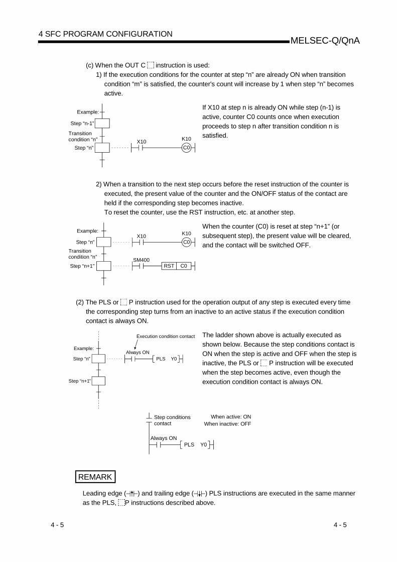
(c) When the OUT C instruction is used:1) If the execution conditions for the counter at step “n” are already ON when transition
condition “m” is satisfied, the counter's count will increase by 1 when step “n” becomesactive.
Step “n-1”
Step “n”
Transition condition “n”
Example:
X10C0K10
If X10 at step n is already ON while step (n-1) isactive, counter C0 counts once when executionproceeds to step n after transition condition n issatisfied.
2) When a transition to the next step occurs before the reset instruction of the counter isexecuted, the present value of the counter and the ON/OFF status of the contact areheld if the corresponding step becomes inactive.To reset the counter, use the RST instruction, etc. at another step.
Step “n”
Step “n+1”
Transition condition “n”
Example:
SM400RST C0
X10C0K10
When the counter (C0) is reset at step “n+1” (orsubsequent step), the present value will be cleared,and the contact will be switched OFF.
(2) The PLS or P instruction used for the operation output of any step is executed every timethe corresponding step turns from an inactive to an active status if the execution conditioncontact is always ON.
Always ONPLS Y0Step “n”
Step “n+1”
Example:
Execution condition contact The ladder shown above is actually executed asshown below. Because the step conditions contact isON when the step is active and OFF when the step isinactive, the PLS or P instruction will be executedwhen the step becomes active, even though theexecution condition contact is always ON.
Always ONPLS Y0
Step conditionscontact
When active: ONWhen inactive: OFF
REMARK
Leading edge ( ) and trailing edge ( ) PLS instructions are executed in the same manneras the PLS, P instructions described above.

4 - 6 4 - 6
MELSEC-Q/QnA4 SFC PROGRAM CONFIGURATION
4.2.2 Initial step
The initial step represents the beginning of a block. Up to 32 initial steps per block can bedesignated.When there are more than one initial step, the coupling enabled is only a selective coupling.Execute the initial steps in the same way as executing the steps other than the initial step.
(1) Active steps at block STARTWhen the block that has more than one initial step is started, the active steps changedepending on the starting method as described below.• When the block START step makes a start using ( m,
m)• When a start is made using the block START instruction
(SET BLm) of the SFC control instructions• When a forced start is made using the block START/END
bit of the SFC information devices• When any of the initial steps is specified using the step
control instruction (SET BLm\Sn, SET Sn) of the SFCcontrol instructions
All initial steps become active.
Only the specified step becomes active.
(2) Transition processing performed when multiple initial steps become active
S8
S4
t4
S0
t0
S7
t7
S3
t3
S6
t6
S2
t2
S5
t5
S1
t1
If steps are selectively coupled in the block that has more than one active initial steps, the stepimmediately after the coupling becomes active if any of the transition conditions immediatelybefore the coupling is satisfied.In the above program example, step 8 (S8) becomes active when any of transition conditionst4 to t7 is satisfied.When, after the step immediately after the coupling (S8 in the above program example)becomes active, another transition condition immediately before the coupling (any of t4 to t7 inthe above program example) is satisfied, reactivation processing is performed as a follow-upfunction.The processing, which will be performed when another transition condition is satisfied with thestep immediately after coupling being active, can be selected between STOP, WAIT andTRANSFER in the "Operation mode at transition to active step (double step START)" (refer toSection 4.7.6) in the block parameter setting of the SFC setting dialog box in the Tools menu.The Basic model QCPU does not allow the operation mode to be selected.It operates in the default "TRANSFER" mode.
(3) The operation of the initial steps with step attributes is the same as that of the other steps.Refer to Section 4.2.4 to Section 4.2.7.

4 - 7 4 - 7
MELSEC-Q/QnA4 SFC PROGRAM CONFIGURATION
4.2.3 Dummy step
A dummy step is a waiting step, etc., which contains no operation output program.
(1) The transition condition following the corresponding step is always checked during executionof a dummy step, and execution proceeds to the next step when the transition condition issatisfied.
(2) The dummy step changes to a step (without step attribute, indication: ) when an operationoutput program is created.
4.2.4 Coil HOLD step SC
A coil HOLD step is a step where the coil output status is maintained in the transition to the nextstep. (The coil output is switched ON by the OUT instruction when the transition condition issatisfied.)
(1) During normal SFC program operation, the coil ON status (switched ON by OUT instructionwhen transition condition is satisfied) is automatically switched OFF before proceeding to thenext step.By designating an operation output step as a “coil HOLD step”, the coil ON status will remainin effect when proceeding to the next step.
[When designated as a coil HOLD step]1) When step n is executed
X1
(ON)Y10(ON)
Y10
n
n+1
SC
When X1 turns ON,Y10 turns ON.
[When not designated as a coil HOLD step]1) When step n is executed
X1
(ON)Y10(ON)
Y10
n
n+1
When X1 turns ON, Y10 turns ON.
2) When a transition to step (n+1) occurs
X1
(ON)Y10(ON)
Y10
n
n+1
SC
(ON)
Remains ON if transition to step(n+1) occurs.
2) When a transition to step (n+1) occurs
X1
(ON)Y10
(OFF)
Y10
n
n+1(OFF)
Y10 turns OFF when transition to step (n+1) occurs.
• At a designated coil HOLD step, “Y10”(switched ON by OUT instruction) willremain ON even when the transitioncondition is satisfied.
• At steps not designated as coil HOLD steps,“Y10” (switched ON by OUT instruction) isautomatically switched OFF when thetransition condition is satisfied.

4 - 8 4 - 8
MELSEC-Q/QnA4 SFC PROGRAM CONFIGURATION
(2) No ladder processing occurs following a transition to the next step. Therefore, the coil outputstatus will remain unchanged even if the input conditions are changed.
X1
(ON)Y10(ON)
Y10
n
n+1
SC
(ON)
X1
(OFF)Y10(ON)
Y10
n
n+1
SC
(ON)
X1:OFF
Since processing of step n is not performed, Y10 remains ON if X1 turns OFF
(3) When a coil ON status (at coil HOLD step) has been maintained to the next step, the coil willbe switched OFF at any of the following times:(a) When the end step of the corresponding block is executed. (Except when SM327 is ON)(b) When an SFC control instruction (RST, BLm) designates a forced END at the block in
question.(c) When an SFC control instruction (RST, BLm\Sn, RST Sn) designates a reset at the block in
question.(d) When a reset occurs at the device designated as the SFC information register's block
START/END device.(e) When a reset step for resetting the step in question becomes active.(f) When the SFC START/STOP command (SM321) is switched OFF.(g) When the coil in question is reset by the program.(h) When the STOP instruction is executed with the stop-time output mode OFF.(i) When S999 is designated at the reset step in the corresponding block.
(4) Block STOP processingMake a block STOP using the STOP/RESTART bit of the SFC information devices or theblock STOP instruction of the SFC control instructions.The processing of the active step in the block where a block STOP was made is as describedbelow.(a) When the "block STOP-time operation output flag (SM325)" is OFF (coil output OFF)
• The step becomes inactive when the processing of the corresponding block is performedfirst after a block STOP request.
• All coil outputs turn OFF.However, the coils turned ON by the SET instruction remain ON.
(b) When the "block STOP-time operation output flag (SM325)" is ON (coil output held)The coil outputs remain ON during a block STOP and after a block RESTART.

4 - 9 4 - 9
MELSEC-Q/QnA4 SFC PROGRAM CONFIGURATION
(5) Precautions when designating coil HOLD steps(a) PLS instruction
When the execution condition of the PLS instruction is satisfied and the transition conditionis satisfied at the same scan where the PLS instruction was executed, the device turnedON by the PLS instruction remains ON until the OFF condition in above (3) is satisfied.
(b) PLF instructionWhen the execution condition of the PLF instruction is satisfied and the transition conditionis satisfied at the same scan where the PLF instruction was executed, the device turnedON by the PLF instruction remains ON until the OFF condition in above (3) is satisfied.
(c) CounterIf the count input condition turns ON/OFF after a transition to the next step, the counterdoes not start counting.
(d) TimerWhen a step transition occurs after the transition condition is satisfied with the coil of thetimer ON, the timer stops timing and holds the then present value.
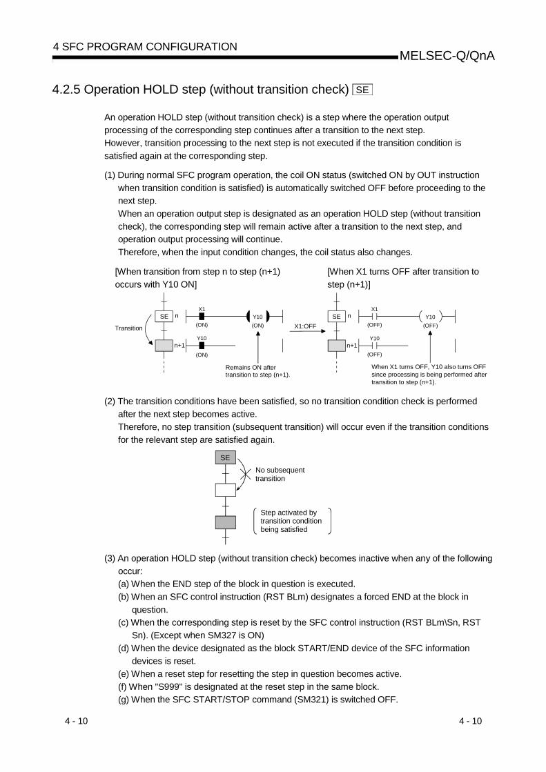
4 - 10 4 - 10
MELSEC-Q/QnA4 SFC PROGRAM CONFIGURATION
4.2.5 Operation HOLD step (without transition check) SE
An operation HOLD step (without transition check) is a step where the operation outputprocessing of the corresponding step continues after a transition to the next step.However, transition processing to the next step is not executed if the transition condition issatisfied again at the corresponding step.
(1) During normal SFC program operation, the coil ON status (switched ON by OUT instructionwhen transition condition is satisfied) is automatically switched OFF before proceeding to thenext step.When an operation output step is designated as an operation HOLD step (without transitioncheck), the corresponding step will remain active after a transition to the next step, andoperation output processing will continue.Therefore, when the input condition changes, the coil status also changes.
[When transition from step n to step (n+1)occurs with Y10 ON]
[When X1 turns OFF after transition tostep (n+1)]
X1
(ON)Y10(ON)
Y10
n
n+1
SE
(ON)
X1
(OFF)Y10
(OFF)
Y10
n
n+1
SE
(OFF)
X1:OFFTransition
Remains ON after transition to step (n+1).
When X1 turns OFF, Y10 also turns OFF since processing is being performed after transition to step (n+1).
(2) The transition conditions have been satisfied, so no transition condition check is performedafter the next step becomes active.Therefore, no step transition (subsequent transition) will occur even if the transition conditionsfor the relevant step are satisfied again.
SENo subsequent transition
Step activated by transition condition being satisfied
(3) An operation HOLD step (without transition check) becomes inactive when any of the followingoccur:(a) When the END step of the block in question is executed.(b) When an SFC control instruction (RST BLm) designates a forced END at the block in
question.(c) When the corresponding step is reset by the SFC control instruction (RST BLm\Sn, RST
Sn). (Except when SM327 is ON)(d) When the device designated as the block START/END device of the SFC information
devices is reset.(e) When a reset step for resetting the step in question becomes active.(f) When "S999" is designated at the reset step in the same block.(g) When the SFC START/STOP command (SM321) is switched OFF.

4 - 11 4 - 11
MELSEC-Q/QnA4 SFC PROGRAM CONFIGURATION
(4) Block STOP processingThe following processing is performed when a block STOP request is issued to thecorresponding block using the STOP/RESTART bit of the SFC information devices or theblock STOP instruction of the SFC control instructions.• STOP status timing
A STOP status is established after the block STOP request output occurs, and processingreturns to the beginning of the block in question.
• Coil outputA coil output OFF or HOLD status will be established, depending on the output mode setting(see Section 4.7.3) at the time of the block STOP designated in the SFC operation mode.However, an ON status will be maintained for coil outputs which were switched ON by theSET instruction.
POINTS(1) When the transition condition immediately before the corresponding step is satisfied or
when the step is reactivated by a JUMP transition, a transition will occur again when thetransition condition is satisfied.
(2) Double STARTs do not apply to reactivated steps.

4 - 12 4 - 12
MELSEC-Q/QnA4 SFC PROGRAM CONFIGURATION
4.2.6 Operation HOLD step (with transition check) ST
An operation HOLD step (with transition check) is a step where the operation output processing ofthe corresponding step continues after a transition to the next step.When the transition condition is satisfied again at the corresponding step, transition processing tothe next step (reactivation) is executed.
(1) During normal SFC program operation, the coil ON status (switched ON by OUT instructionwhen transition condition is satisfied) is automatically switched OFF before proceeding to thenext step.When an operation output step is designated as an operation HOLD step (with transitioncheck), the corresponding step will remain active after a transition to the next step, andoperation output processing will continue.Therefore, when the input condition changes, the coil status also changes.
[When transition from step n to step (n+1) occurswith Y10 ON]
[When X1 turns OFF after transition tostep (n+1)]
X1
(ON)Y10(ON)
Y10
n
n+1
ST
(ON)
X1
(OFF)Y10
(OFF)
Y10
n
n+1
ST
(OFF)
X1:OFFTransition
Remains ON after transition to step (n+1).
When X1 turns OFF, Y10 also turns OFF since processing is being performed after transition to step (n+1).
(2) The transition condition will be checked after the transition condition is satisfied and the nextstep is activated.Hence, when the transition condition of the corresponding step is satisfied again, a transition tothe next step (subsequent transition) occurs to activate it.At this time, the current step remains active.
(Transition is executed again)
X0Y10
X1PLS M0
M0Tran
ST
Step activated by previous transition condition being satisfied

4 - 13 4 - 13
MELSEC-Q/QnA4 SFC PROGRAM CONFIGURATION
POINTS(1) Convert the transition conditions into pulses.
If they are not pulsed, transition processing to the next step is performed every scan whilethe condition is satisfied.
(2) When a double START occurs as the transition condition was satisfied with the transitiondestination step being active, the processing changes depending on the parameter setting.The Basic model QCPU does not allow the parameters to be selected.It operates in the default "Transfer" mode.Refer to Section 4.7.6 for the parameter setting and the processing performed for eachsetting.
(3) The difference between the operation HOLD step (with transition check) and the operationHOLD step (without transition check) is whether the next step will be activated or not as afollow-up when the transition condition is satisfied again.
(3) An operation HOLD step (with transition check) becomes inactive when any of the followingoccur:(a) When the end step of the corresponding block is executed. (Except when SM327 is ON)(b) When an SFC control instruction (RST BLm) designates a forced END at the block in
question.(c) When an SFC control instruction (RST BLm\Sn, RST Sn) designates a reset at the block in
question.(d) When a reset occurs at the device designated as the SFC information register's block
START/END device.(e) When a reset step for resetting the step in question becomes active.(f) When "S999" is designated at the reset step in the same block.(g) When the SFC START/STOP command (SM321) is switched OFF.
(4) Block STOP processingMake a block STOP using the STOP/RESTART bit of the SFC information devices or theblock STOP instruction of the SFC control instructions.The processing of the active step in the block where a block STOP was made is as describedbelow.(a) When the "block STOP-time operation output flag (SM325)" is OFF (coil output OFF)
The step becomes inactive when the processing of the corresponding block is performedfirst after a block STOP request.• All coil outputs turn OFF.• However, the coils turned ON by the SET instruction remain ON.
(b) When the "block STOP-time operation output flag (SM325)" is ON (coil output held)The coil outputs remain ON during a block STOP and after a block RESTART.

4 - 14 4 - 14
MELSEC-Q/QnA4 SFC PROGRAM CONFIGURATION
4.2.7 Reset step R
A reset step is a step which designates a forced deactivation of another specified step (operationoutput).The reset step deactivates the designated step in the current block before execution of theoperation output every scan.Except the deactivation of the specified step, the reset step execute the operation output with thesame functions as a normal step (without step attributes).
When a reset step isactivated, a specifiedstep is deactivated(reset).
R
n
Sn
(1) When deactivating only the designated stepSet the step number to be deactivated to the specified step number Sn.
(2) When deactivating all the held stepsSet "999" to the specified step number Sn.When the number of the specified step is "999", all held steps of the coil HOLD steps,operation HOLD steps (without transition check) and operation HOLD steps (with transitioncheck) in the current block are batch-deactivated.
POINTOnly held steps can be deactivated by the reset step.The following steps are not the targets of the reset step.• HOLD steps that are active but not held• Steps that are not specified as the HOLD steps

4 - 15 4 - 15
MELSEC-Q/QnA4 SFC PROGRAM CONFIGURATION
4.2.8 Block START step (with END check)
A block START step (with END check) is the step where the specified block is started, and whenthe START destination block is then deactivated, the check of the transition condition to the nextstep is started.
(1) The operation of the block START step (with END check) is described below.(a) When activated, the block START step (with END check) starts the specified block.(b) No processing is performed until the START destination block is deactivated after its
execution has ended.(c) When the START destination block is deactivated after its execution has ended, only the
transition condition check is performed.(d) When the transition condition is satisfied, a transition to the next step occurs.
Block m
m
(2) A simultaneous start cannot be made for a single block.The block that has already started cannot be started, either.If either of the above starts is made, the following processing is performed depending on thesetting of the operation mode at block double START. *1(Refer to Section 4.7.5 for details of the operation at block double START.)(a) When the setting of the operation mode at block double START is "STOP"
A "BLOCK EXE. ERROR" (error code: 4620) occurs and the CPU module stopsprocessing.
(b) When the setting of the operation mode at block double START is the default setting of"WAIT"Processing is not performed and waits until the START destination block ends itsexecution.
POINTS*1: The Basic model QCPU does not allow the setting of the operation mode at block double
START.For the Basic model QCPU, the operation mode at block double START is "WAIT" only.
(3) A block START request can start multiple blocks simultaneously by performing a paralleltransition (refer to Section 4.3.3).The steps in the simultaneously started blocks are processed in parallel.

4 - 16 4 - 16
MELSEC-Q/QnA4 SFC PROGRAM CONFIGURATION
(4) The following table indicates the number of steps that can be executed simultaneously in allblocks and the maximum number of active steps in a single block.
CPU Module Model nameNumber of Steps That Can Be
Executed Simultaneously in All BlocksMaximum Number of Active
Steps in Single Block
Basic mode QCPU 1024 steps 128 stepsHigh Performance model QCPUProcess CPUQnACPU
1280 steps 256 steps
POINTS(1) The block START step (with END check) cannot be described immediately before the
coupling of a parallel coupling.(The block START step (with END check) cannot be used for a wait.)The block START step (without END check) can be described immediately before thecoupling of a parallel coupling.
(2) The execution status of each block can be checked at another block using the blockSTART/END bit (refer to Section 4.5.1) of the SFC information devices or the blockactivation check instruction (refer to Section 4.4.3) of the SFC control instructions.

4 - 17 4 - 17
MELSEC-Q/QnA4 SFC PROGRAM CONFIGURATION
4.2.9 Block START step (without END check)
A block START step (without END check) is the step where the specified block is started, and ifthe START destination block is active, the check of the transition condition to the next step isperformed.
(1) The operation of the block START step (without END check) is described below.(a) When activated, the block START step (without END check) starts the specified block.(b) After starting the specified block, the step performs only the check of the transition
condition.(c) When the transition condition is satisfied, execution proceeds to the next step without
waiting for the START destination block to end.
X0TRAN
Block m
m
(When transition condition is satisfied)
(2) A simultaneous start cannot be made for a single block.The block that has already started cannot be started, either.If either of the above starts is made, the following processing is performed depending on thesetting of the operation mode at block double START. *1(Refer to Section 4.7.5 for details of the operation at block double START.)(a) When the setting of the operation mode at block double START is "STOP"
A "BLOCK EXE. ERROR" (error code: 4620) occurs and the CPU module stopsprocessing.
(b) When the setting of the operation mode at block double START is the default setting of"WAIT"Processing is not performed and waits until the START destination block ends itsexecution.
POINTS*1: The Basic model QCPU does not allow the setting of the operation mode at block double
START.For the Basic model QCPU, the operation mode at block double START is "WAIT" only.
(3) A block START request can start multiple blocks simultaneously by performing a paralleltransition (refer to Section 4.3.3).The steps in the simultaneously started blocks are processed in parallel.
(4) The number of steps that can be executed simultaneously is a total of up to 1280 steps*1 forall blocks.The number of steps that can be executed simultaneously in a single block is a maximum of256 steps*2 including those of the HOLD steps.*1: Up to 1024 steps for the Basic model QCPU.*2: Up to 128 steps for the Basic model QCPU.

4 - 18 4 - 18
MELSEC-Q/QnA4 SFC PROGRAM CONFIGURATION
POINTSThe execution status of each block can be checked at another block using the blockSTART/END bit (refer to Section 4.5.1) or the block activation check instruction (refer toSection 4.4.3) of the SFC control instructions.

4 - 19 4 - 19
MELSEC-Q/QnA4 SFC PROGRAM CONFIGURATION
4.2.10 End step
An end step indicates that a series of processings in the corresponding block is all ended.
(1) When the end step is reached, the following processing is performed to end the block.(a) All steps in the block are deactivated.
(The held step are also deactivated.)(b) The coil outputs turned ON by the OUT instruction are all turned OFF.
When the special relay for output mode at end step execution (SM327) is ON, however, thecoil outputs of the held steps all remain ON.
POINTS(1) SM327 is valid only when the end step is reached.
When a forced end is made by the block END instruction, etc., the coil outputs of all stepsare turned OFF.
(2) SM327 is valid for only the HOLD steps being held.The outputs of the HOLD steps that are not held as the transition conditions are notsatisfied are all turned OFF.
(2) When the special relay for clear processing mode at arrival at end step (SM328) is turned ON,the execution of the active step other than the one held in the block can be continued when theend step is reached. *1(The block is not ended if the end step is executed.)However, when there is only the held step left in the block at arrival at the end step, the heldstep is deactivated and the block ends if SM328 is ON.
When SM328 is turned ON, processing of active step is continued.
Transition
When there is normal active step left
Transition
SE
When there is HOLD step, whose transition condition is not satisfied (which is not held), left
Transition
SE
When there is held active step left
When SM328 is turned ON, processing of HOLD step is continued.
Block is ended independently of whether SM328 is ON or OFF.
REMARK
*1: SM328 that continues the execution of the active step other than the one held in the blockcan be used with the Basic model QCPU only.

4 - 20 4 - 20
MELSEC-Q/QnA4 SFC PROGRAM CONFIGURATION
POINTSThe following gives the precautions to be taken when SM328 is turned ON(1) When there is only the held step left at arrival at the end step, that held step is deactivated
if SM328 is ON.When the user does not want to turn OFF the coil output of the held step suddenly, it canbe prevented by turning ON SM327.
(2) If a block is started at the block START step when SM328 is ON, execution returns to thesource as soon as there are no non-held active steps in the block.
(3) Do not describe an always satisfied transition condition immediately after the operationHOLD step (with transition check).
Step n
Step (n+1)
Block n Block m
Step m
Step (m+1)
3)
2)
ST1)
SM400Tran n
M0Tran n
1) Since the transition condition is alwayssatisfied, step (m+1) remains an activestep (non-held active status).
2) If M0 turns ON and the transitioncondition is satisfied, block m cannotbe ended.
3) Since block m is not ended, executioncannot proceed to step (n+1).
(a) When the transition condition immediately after the operation HOLD step (with transitioncheck) is always satisfied, the next step is kept in a "non-held active status". Therefore,the block cannot be ended when SM328 is ON.Further, if this block has been started at the block START step (with END check),processing cannot be returned to the START source step.
(b) When it is desired to describe an always satisfied transition condition immediately afterthe operation HOLD step (with transition check), make provision so that the block canbe forcibly ended from outside.
(3) After end step execution, a restart is performed as described below.Block No. Restarting Method
START condition of block 0 isset to "Auto START ON" in theSFC setting of the PLCparameter dialog box
• Execution automatically returns to the initial step again, andprocessing is executed repeatedly.
Block 0START condition of block 0 isset to "Auto START OFF" in theSFC setting of the PLCparameter dialog box
All blocks other than block 0
• A restart is made when any of the following is executed.1) When another START request is received from another block
(when the block START step is activated)2) When the block START instruction of the SFC control
instructions is executed3) When the block START/END bit of the block information
devices is forcibly turned ON

4 - 21 4 - 21
MELSEC-Q/QnA4 SFC PROGRAM CONFIGURATION
4.2.11 Instructions that cannot be used with operation outputs
Table 4.1 indicates the instructions that cannot be used with operation outputs.
Table 4.1 Unusable Instruction List
Class Instruction Symbol Symbol Function RemarksMC MC N No.1_D Master control set
Master controlMCR MCR N Master control resetFEND FEND Main routine program end
EndEND END Sequence program endCJ CJ P Conditional jumpSCJ SCJ P Delayed jumpJMP JMP P Unconditional jump
Label P cannot beused, either.Program branch
GOEND GOEND Jump to END
Program control IRET IRET Return from interrupt programLabel I cannot beused, either.
BREAK BREAK D P Repetitive forced endStructuring
RET RET Return from subroutineCHKST *1 CHKST CHK instruction startCHK *1 CHK Specific format error checkCHKCIR *1 CHKCIR Check pattern change start
Debuggingtroubleshooting
CHKEND *1 CHKEND Check pattern change endSFCP SFCP SFC program startSFCPEND SFCPEND SFC program endBLOCK BLOCK S SFC block startBEND BEND SFC block endSTEP? STEP? S ? = N, D, SC, SE, ST, R, C, G, I, ID, ISC, ISE, IST, IR
SFC step start
TRAN? TRAN? S
? = L, O, OA, OC, OCA, A, C, CA, CO, COC
SFC transition start
TAND TAND S SFC coupling checkTSET TSET S SFC transition destination designation
SFC dedicatedinstruction
SEND SEND SFC step end
*1: Instructions not supported by the Basic model QCPU.
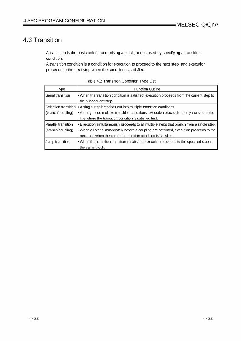
4 - 22 4 - 22
MELSEC-Q/QnA4 SFC PROGRAM CONFIGURATION
4.3 Transition
A transition is the basic unit for comprising a block, and is used by specifying a transitioncondition.A transition condition is a condition for execution to proceed to the next step, and executionproceeds to the next step when the condition is satisfied.
Table 4.2 Transition Condition Type List
Type Function Outline
Serial transition • When the transition condition is satisfied, execution proceeds from the current step tothe subsequent step.
Selection transition(branch/coupling)
• A single step branches out into multiple transition conditions.• Among those multiple transition conditions, execution proceeds to only the step in the
line where the transition condition is satisfied first.Parallel transition(branch/coupling)
• Execution simultaneously proceeds to all multiple steps that branch from a single step.• When all steps immediately before a coupling are activated, execution proceeds to the
next step when the common transition condition is satisfied.Jump transition • When the transition condition is satisfied, execution proceeds to the specified step in
the same block.

4 - 23 4 - 23
MELSEC-Q/QnA4 SFC PROGRAM CONFIGURATION
4.3.1 Serial transition
“Serial transition” is the transition format in which processing proceeds to the step immediatelybelow the current step when the transition condition is satisfied.
Step “n+1” (operation output [B])
Step “n” (operation output [A])
Transition condition “b”
• When transition condition “b” becomes satisfied at step “n”(operation output [A]) execution, operation output [A] willbe deactivated, and processing will proceed to step “n+1”(operation output [B]).
(1) A maximum of 512*1 serial transition steps ( , , ) can be described in each block.Therefore, a maximum of 512* serial transitions (+) can be described.However, there is a restriction on the number of lines as indicated below depending on theSFC display column setting.*1: 128 for the Basic model QCPU
Max. of512 serialtransitions
Max. of1536 lines
Numberof lines
Number of columns (max. of 32)
Number of linesApprox.3000
SFC display column setting value (n)
When SFC display columnsetting is “1” or “2”
When SFC displaycolumn setting is “n”
Examples of the permissible number of lines corresponding to a few SFC display column setting values are shown below. The SFC dis- play column setting value can be designated freely within a 1 to 32 range.
SFC Display Col-umn setting
Number of LinesPossible
1/2 15368 384
16 192222832
13810896

4 - 24 4 - 24
MELSEC-Q/QnA4 SFC PROGRAM CONFIGURATION
(2) Serial transition operation flowchart
Initial step
Transition condition “a”
Step 1
Transition condition “b”
Step 2
Transition condition “c”
Step 3
END stepTransition condition “d”
1
Operation status
Initial step operation output executed.
Transition condition “a” satisfied?
Initial step operation outputdeactivated.
Step 1 operation output executed.
Transition condition “b” satisfied?
Step 1 operation output deactivated.
Step 2 operation output executed.
Transition condition “c” satisfied?
Step 2 operation output deactivated.
Step 3 operation output executed.
Transition condition “d” satisfied?
Step 3 operation output deactivated.
END step executed, operationcompleted.
1 For steps with attribute designations, processing occurs in accordance with the attributes.
YES
NO
YES
NO
NO
YES
YES
NO
1
1
1

4 - 25 4 - 25
MELSEC-Q/QnA4 SFC PROGRAM CONFIGURATION
4.3.2 Selection transition
A “selection transition” is the transition format in which several steps are coupled in a parallelmanner, with processing occurring only at the step where the transition condition is satisfied first.
Branch Step “n+1”(operation output [B])
Step “n”(operation output [A])
Transition condition “b”Step “n+2”(operation output [C])
Transition condition “c”
• From step “n”, processing will proceed to eitherstep “n+1” or step “n+2”, depending on whichtransition condition (“b” or “c”) is satisfied first.
• If both transition conditions are satisfiedsimultaneously, the condition to the left will takeprecedence.Step “n” will then be deactivated.
• Subsequent processing will proceed from step tostep in the selected column until another parallelcoupling selection occurs.
Coupling
Step “n”(operation output [A])
Step “n+1”(operation output [B])
Transition condition “b” Transition condition “c”
Step “n+2”(operation output [C])
• When the transition condition (“b” or “c”) at theexecuted branch is satisfied, the executed step([A] or [B]) will be deactivated, and processingwill proceed to step “n+2”.
(1) Up to 32 steps can be available for selection in the selection transition format.
Step “n+1”
Step “n”
Max. of 32 steps
Step “n+2”
Step “n+3”
Step “n+4”
Step “n+32”
(2) When two or more selection step transition conditions are satisfied simultaneously, the left-most condition will take precedence.
Step “n+1”
Step “n”
Step“n+2”
Step“n+3”
Step“n+4”
Transitioncondition “b”
Transitioncondition “c”
Transitioncondition “d”
Transitioncondition “e”
Example: If transition conditions “c”and “d” are satisfiedsimultaneously, the step“n+2” operation output willbe executed.

4 - 26 4 - 26
MELSEC-Q/QnA4 SFC PROGRAM CONFIGURATION
(3) In a selection transition, a coupling can be omitted by a jump transition or end transition.
Step“n+4”
Transitioncondition “c”
Transitioncondition “b”
Step“n+1”
Step“n+2”
Step“n+3”
Transitioncondition “d”
n
Step“n+5”
Step n
When transition condition “b” is satisfied at thestep “n” operation output, processing willproceed in order through steps “n+1”, “n+2”and “n+3”. When transition condition “d” issatisfied, processing will jump to step “n”. (Fordetails on “jump transitions”, see Section4.3.4.)
POINTSIn a selective transition, the number of branches and the number of couplings may be different.However, a selection branch and parallel coupling or a parallel branch and selection couplingcannot be combined.
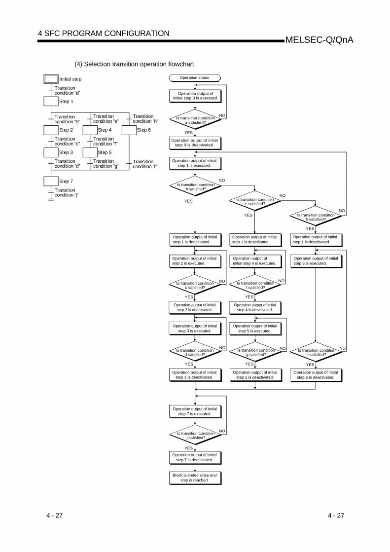
4 - 27 4 - 27
MELSEC-Q/QnA4 SFC PROGRAM CONFIGURATION
(4) Selection transition operation flowchart
Step 2 Step 4 Step 6
Step 1
Transitioncondition “b”
Transitioncondition “e”
Transitioncondition “h”
Step 3 Step 5
Transitioncondition “c”
Transitioncondition “f”
Transitioncondition “d”
Transitioncondition “g”
Transitioncondition “i”
Step 7
Transitioncondition “j”
Initial step
Transitioncondition “a”
Is transition condition a satisfied?
Operation output of initial step 0 is executed.
YES
YES
YESYES
NO
Operation output of initial step 0 is deactivated.
YESYES
YES
YES
NO
NO
NO
NO
NO NO
YES
YES
NO
NO
NO
Operation status
Operation output of initial step 1 is executed.
Is transition condition b satisfied?
Operation output of initial step 1 is deactivated.
Operation output of initial step 2 is executed.
Is transition condition c satisfied?
Operation output of initial step 2 is deactivated.
Operation output of initial step 3 is executed.
Is transition condition d satisfied?
Operation output of initial step 3 is deactivated.
Operation output of initial step 7 is executed.
Is transition condition j satisfied?
Operation output of initial step 7 is deactivated.
Block is ended since end step is reached.
Is transition condition e satisfied?
Operation output of initial step 1 is deactivated.
Operation output of initial step 4 is executed.
Is transition condition f satisfied?
Operation output of initial step 4 is deactivated.
Operation output of initial step 5 is executed.
Is transition condition g satisfied?
Operation output of initial step 5 is deactivated.
Is transition condition h satisfied?
Operation output of initial step 1 is deactivated.
Operation output of initial step 6 is executed.
Is transition condition i satisfied?
Operation output of initial step 6 is deactivated.

4 - 28 4 - 28
MELSEC-Q/QnA4 SFC PROGRAM CONFIGURATION
4.3.3 Parallel transition
“Parallel transition” is the transition format in which several steps linked in parallel are processedsimultaneously when the relevant transition condition is satisfied.
Branch
Step “n”(operation output [A])
Transition condition “b”
Step “n+1”(operationoutput [B])
Step “n+3”(operationoutput [D])
Step “n+2”(operationoutput [C])
Step “n+4”(operationoutput [E])
Transition condition “c” Transition condition “d”
• From step “n”, processing will proceedsimultaneously to steps “n+1” and “n+3” whentransition condition “b” is satisfied.
• Processing will proceed to step “n+4” whentransition condition “c” is satisfied, and to step“n+4” when transition condition “d” is satisfied.
Coupling
Step “n”(operationoutput [A])
Transition condition “b”
Waiting step Waiting step
Step “n+2”(operationoutput [C])
Step “n+1”(operationoutput [B])
Transition condition “d”
Transition condition “c”
• When transition conditions “b” and “c” aresatisfied at step “n” and step “n+1” execution,steps “n” and “n+1” will be deactivated, andprocessing will proceed to the waiting steps.
• Waiting steps are used to synchronize parallelprocessing operations. Parallel processingsteps always proceed to a waiting step. Whencondition “d” is satisfied at the waiting steps,processing will proceed to step “n+2”.
• Waiting steps are dummy steps which requireno operation output ladder.
(1) Up to 32 steps can processed simultaneously with the parallel transition format.
Step “n”
Step“n+1”
Step“n+2”
Step“n+32”
Step“n+3”
Step“n+4”
Up to 32 steps

4 - 29 4 - 29
MELSEC-Q/QnA4 SFC PROGRAM CONFIGURATION
(2) If another block is started by the parallel processing operation, the START source block andSTART destination block will be executed simultaneously. (In the example below, processingfrom step “n+1” will be executed simultaneously with block 1.)
Step“n+1”
Step “n”Transitioncondition “b”
Transitioncondition
Block 1 START
Transitioncondition
Block 0
When condition “b” is satisfied at step “n”execution, processing will proceed to step“n+1” and block 1 will be started. Blocks “0”and “1” will then be processed simultaneously.
(3) The following table indicates the number of steps that can be executed simultaneously in allblocks and the maximum number of active steps in a single block.If the number of simultaneously processed steps exceeds the value in the following table, anerror occurs and the CPU module stops processing.
CPU Module Model nameNumber of Simultaneously
Processed StepsMaximum Number of Active
Steps in Single Block
Basic mode QCPU 1024 steps 128 stepsHigh Performance model QCPUProcess CPUQnACPU
1280 steps 256 steps
(4) Couplings must be provided when the parallel transition format is used. Program creation isimpossible without couplings.Example: Program without couplings (Cannot be designated)
END step
END step
Each column endsat the END step. Jump transition (see Section 4.3.4)
occurs without coupling
Jump

4 - 30 4 - 30
MELSEC-Q/QnA4 SFC PROGRAM CONFIGURATION
(5) As a rule, a waiting step must be created prior to the coupling.However, in cases such as the example below where each of the parallel transition columnsconsist of only 1 step (program without a transition condition between the parallel transitionbranch and the coupling), a waiting step is not required.

4 - 31 4 - 31
MELSEC-Q/QnA4 SFC PROGRAM CONFIGURATION
(6) Parallel transition operation flowchart
Step 2 Step 3 Step 4
Step 1
Transitioncondition “b”
Waitingstep
Waitingstep
Transitioncondition “c”
Transitioncondition “d”
Transitioncondition “f”
Step 5
Transitioncondition “g”
Initial step
Transitioncondition “a”
Waitingstep
Transitioncondition “e”
NO
1 For steps with attribute designations, processing occurs in accordance with the attributes.
Step 5 operation outputdeactivated.
Step 5 operation outputexecuted.
Step 2 operation outputdeactivated.
Transition condition“f” satisfied?
Transition condition“c” satisfied?
Step 2 operation outputexecuted.
Step 1 operation outputdeactivated.
Transition condition“b” satisfied?
Step 1 operation outputexecuted.
Initial step operation outputdeactivated.
Transition condition“a” satisfied?
Operation status
Initial step operation outputexecuted.
1YES
YES
NO
1
NO
NO
YES
YES 1
Waiting step executed.
NO
YES
NO
YES 1
Step 3 operation outputexecuted.
Step 4 operation outputexecuted.
Transition condition“d” satisfied?
Transition condition“e” satisfied?
Step 4 operation outputdeactivated.
Step 3 operation outputdeactivated.
All waiting stepsexecuted?
YES
NO
YES 1
Transition condition“g” satisfied?
END step executed,operation completed.
NO
Parallel processing
Waiting step executed. Waiting step executed.
1

4 - 32 4 - 32
MELSEC-Q/QnA4 SFC PROGRAM CONFIGURATION
4.3.4 Jump transition
A “jump transition” is a jump to a specified step within the same block which occurs when thetransition condition is satisfied.
m
Step “n”(operation output [A])
Transition condition “b”Step “m”(operation output [B])
• When condition “b” is satisfied at step “n”execution, step “n” (operation output [A]) isdeactivated, and processing proceeds to step“m”.
(1) There are no restrictions regarding the number of jump transitions within a single block.(2) In the parallel transition format, only jumps in the vertical direction are possible at each of the
branches.Example 1: Jump transition program in vertical direction from branch to coupling
n
n
A program of a jump transition to another vertically branched ladder, a jump transition forexiting from a parallel branch, or a jump transition to a parallel branch from outside a parallelbranch cannot be created.Example 2: Program for exiting from parallel branch (cannot be designated)
No parallel coupling
Parallel transition
Jump transition
(3) Do not specify a jump transition to the current step when the transition condition is satisfied asshown below. Normal operation is not performed when a jump transition to the current step isdesignated.
n
n
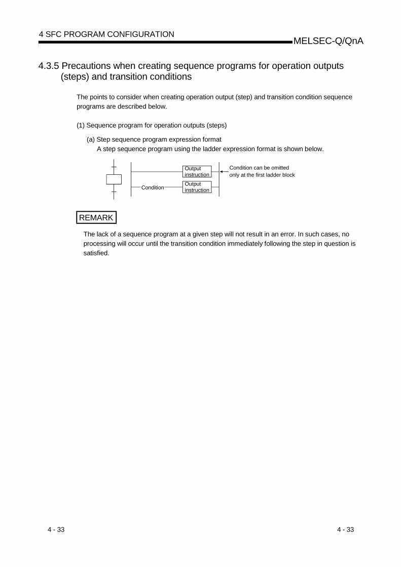
4 - 33 4 - 33
MELSEC-Q/QnA4 SFC PROGRAM CONFIGURATION
4.3.5 Precautions when creating sequence programs for operation outputs(steps) and transition conditions
The points to consider when creating operation output (step) and transition condition sequenceprograms are described below.
(1) Sequence program for operation outputs (steps)
(a) Step sequence program expression formatA step sequence program using the ladder expression format is shown below.
OutputinstructionOutputinstructionCondition
Condition can be omittedonly at the first ladder block
REMARK
The lack of a sequence program at a given step will not result in an error. In such cases, noprocessing will occur until the transition condition immediately following the step in question issatisfied.

4 - 34 4 - 34
MELSEC-Q/QnA4 SFC PROGRAM CONFIGURATION
(2) Sequence program for transition condition
(a) Transition condition sequence program expression formatA transition condition sequence program using the ladder expression format is shownbelow.
Condition
TRAN [TRAN] is a dummy outputCondition
(b) Instructions usedInstructions which can be used in a transition condition sequence program are listed below.
CPU Module Type
Class InstructionCode Symbol Function Basic model
QCPU
HighPerformanceModel QCPU,Process CPU,
QnACPULD
ANDOR
Operation START (N/O contact)Serial connection (N/O contact)Parallel connection (N/O contact)
ContactsLDIANIORI
Operation START (N/C contact)Serial connection (N/C contact)Parallel connection (N/C contact)
LDPANDPORP
Leading edge pulse operation STARTLeading edge pulse serial connectionLeading edge pulse parallel connection
ContactsLDF
ANDFORF
Trailing edge pulse operation STARTTrailing edge pulse serial connectionTrailing edge pulse parallel connection
ANBORB
Ladder block serial connectionLadder block parallel connection
INV Operation result inversion
MEPMEF
Operation results converted to leadingedge pulse (step memory)Operation results converted to trailingedge pulse (step memory)
Coupling
EGPEGF
VV
Operation results converted to leadingedge pulse (memory)Operation results converted to trailingedge pulse (memory)
: Usable, : Unusable

4 - 35 4 - 35
MELSEC-Q/QnA4 SFC PROGRAM CONFIGURATION
CPU Module Type
Class InstructionCode Symbol Function Basic model
QCPU
HighPerformanceModel QCPU,Process CPU,
QnACPU
LD AND OR
LD AND S1 S2
OR (=, <>, >, >=, <, <=)
BIN16 bit data comparison
LDD ANDD ORD
LDD ANDD S1 S2
ORD (=, <>, >, >=, <, <=)
BIN32 bit data comparison
LDE ANDE ORE
LDE ANDE S1 S2
ORE (=, <>, >, >=, <, <=)
Floating decimal point data comparison
Comparisonoperation
LD$ AND$ OR$
LD$ AND$ S1 S2
OR$ ! (=, <>, >, >=, <, <=)
Character string data comparison
: Usable, : Unusable
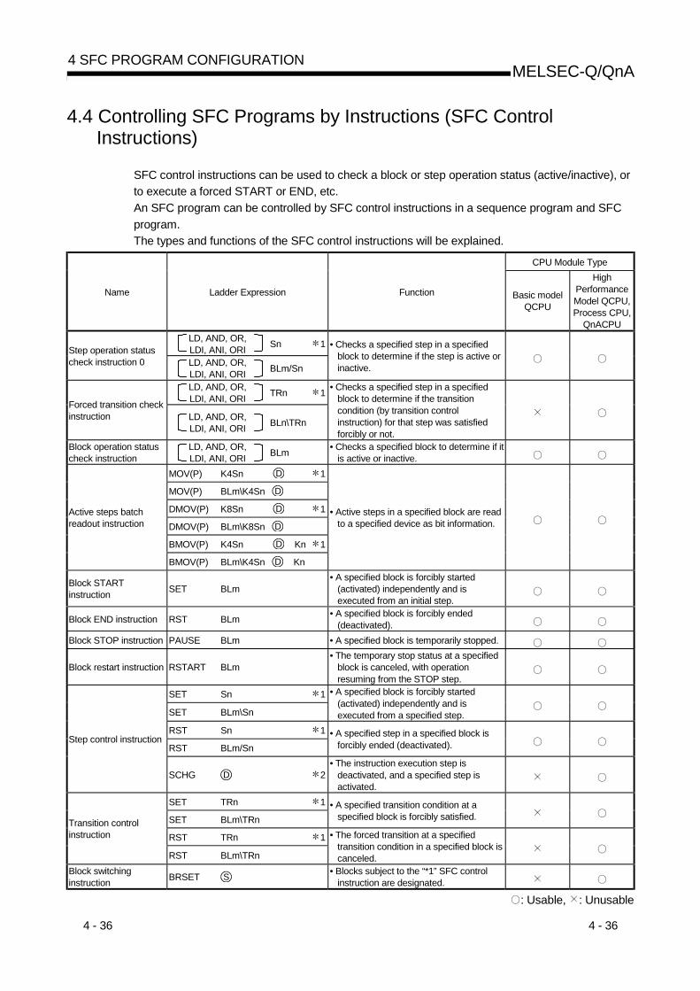
4 - 36 4 - 36
MELSEC-Q/QnA4 SFC PROGRAM CONFIGURATION
4.4 Controlling SFC Programs by Instructions (SFC ControlInstructions)
SFC control instructions can be used to check a block or step operation status (active/inactive), orto execute a forced START or END, etc.An SFC program can be controlled by SFC control instructions in a sequence program and SFCprogram.The types and functions of the SFC control instructions will be explained.
CPU Module Type
Name Ladder Expression Function Basic modelQCPU
HighPerformanceModel QCPU,Process CPU,
QnACPULD, AND, OR,LDI, ANI, ORI Sn 1Step operation status
check instruction 0 LD, AND, OR,LDI, ANI, ORI BLm/Sn
• Checks a specified step in a specifiedblock to determine if the step is active orinactive.
LD, AND, OR,LDI, ANI, ORI TRn 1
Forced transition checkinstruction LD, AND, OR,
LDI, ANI, ORI BLn\TRn
• Checks a specified step in a specifiedblock to determine if the transitioncondition (by transition controlinstruction) for that step was satisfiedforcibly or not.
Block operation statuscheck instruction
LD, AND, OR,LDI, ANI, ORI BLm • Checks a specified block to determine if it
is active or inactive.MOV(P) K4Sn D 1
MOV(P) BLm\K4Sn D
DMOV(P) K8Sn D 1
DMOV(P) BLm\K8Sn D
BMOV(P) K4Sn D Kn 1
Active steps batchreadout instruction
BMOV(P) BLm\K4Sn D Kn
• Active steps in a specified block are readto a specified device as bit information.
Block STARTinstruction SET BLm
• A specified block is forcibly started(activated) independently and isexecuted from an initial step.
Block END instruction RST BLm • A specified block is forcibly ended(deactivated).
Block STOP instruction PAUSE BLm • A specified block is temporarily stopped.
Block restart instruction RSTART BLm• The temporary stop status at a specified
block is canceled, with operationresuming from the STOP step.
SET Sn 1
SET BLm\Sn
• A specified block is forcibly started(activated) independently and isexecuted from a specified step.
RST Sn 1
RST BLm/Sn• A specified step in a specified block is
forcibly ended (deactivated).Step control instruction
SCHG D 2• The instruction execution step is
deactivated, and a specified step isactivated.
SET TRn 1
SET BLm\TRn• A specified transition condition at a
specified block is forcibly satisfied.
RST TRn 1Transition controlinstruction
RST BLm\TRn
• The forced transition at a specifiedtransition condition in a specified block iscanceled.
Block switchinginstruction BRSET S • Blocks subject to the “*1” SFC control
instruction are designated.
: Usable, : Unusable

4 - 37 4 - 37
MELSEC-Q/QnA4 SFC PROGRAM CONFIGURATION
1: In a sequence program, block 0 is the instruction execution target block.In an SFC program, the current block is the instruction execution target block.The instruction execution target block can be changed with the block switching instruction(BRSET).However, the Basic model QCPU cannot execute it.
2: Can be used at the step of an SFC program.An error occurs if it is executed in a sequence program other than an SFC program.
POINTS(1) Either of the following errors occurs if the SFC control instruction is executed from the
sequence program when the special relay for SFC program start/stop (SM321) is OFF.• Instruction that specifies a block: BLOCK EXE. ERROR (error No.: 4621)• Instruction that specifies a step: STEP EXE. ERROR (error No.: 4631)
(2) The SFC block (BL) and step relay (S) cannot be index-qualified.(3) Do not use the SFC control instructions in an "interrupt program" or "fixed-cycle execution
type program".If they are used in an "interrupt program" or "fixed-cycle execution type program",operation of the SFC program cannot be guaranteed.
(4) The step relay (S) can be used in only the following instructions.• Step activation check instruction• Active step batch read instruction• Step START instruction• Step END instruction

4 - 38 4 - 38
MELSEC-Q/QnA4 SFC PROGRAM CONFIGURATION
POINT
Beginning from Section 4.4.1 of this manual, the following table is used in the explanations ofthe various instructions. The table contents are explained below.
Usable Devices Programs Using Instructions Execution Site
Internal Device(System, User)
MELSECNET/10 DirectJ \
SFC Program
Bit Word
FileRegister
RBit Word
SpecialFunctionModule
U \G
IndexZ
ConstantK, H
ExpansionSFC
BLm\SnOther
DataType Sequence
ProgramStep
TransitionCondition
Block StepTransitionCondition
S BIN16/BIN32
DBIN16/BIN32
4)2) 5)1) 3)
1) Ladder symbols are indicated in this area.
MOV DS
DestinationSourceInstruction code
Destination ...................................Data destination following the operation.Source ..........................................Where data is stored prior to the operation.
2) Usable devices are indicated at this area.• Devices indicated by a circle mark (O) can be used with the instruction in question.
The device application classifications are shown below.

4 - 39 4 - 39
MELSEC-Q/QnA4 SFC PROGRAM CONFIGURATION
Internal(System, User)
MELSECNET/10(H)Direct
J \ DeviceClass
Bit Word
FileRegister
RBit Word
SpecialFunctionModule
U \G
IndexZ
ExpansionSFC
Constant Other
Usabledevices
FX, FY,S, SM,X, Y,M,L, F,V,B, T,C, SB
A, VD,SD, T, C,D, W,SW, FD,ST
R, ZR J \XJ \YJ \BJ \SB
J \WJ \SW
U \G Z BLm\SnBLm\Trm
Decimalhexadecimalreal numberconstantcharacter stringconstant
P, I,J, U,DX,DY,N, BL,TR,BL\S
• When a device name is indicated in the “constant”, “expansion SFC”, or the “other” column,only that device may be used.Example:If “K, H” is indicated in the “constant” column, only a decimal (K) or hexadecimal (H) constantmay be used.Real number constants (E) and character string constants ($) may not be used.
3) The data type for the designated device is indicated here.• Bit................................... Indicates a bit data operation.• BIN16 ............................ Indicates 16-bit binary value processing. 1 word used.• BIN32 ............................ Indicates 16-bit binary value processing. 2 words used.• Character string ............ Indicates character Variable
string processing. numberof words.
• Device Indicates............ device name and Variablefirst device processing. number
of words.
4) The type of program which can be used with the instruction in question is indicated here.
5) The request destination for the instruction in question is indicated here.

4 - 40 4 - 40
MELSEC-Q/QnA4 SFC PROGRAM CONFIGURATION
High PerformanceQnA Q4AR
Basic
QCPUPLC CPU Process CPU
: First five digits of serial No. are 04122 or later.
4.4.1 Step operation status check instructions (LD, LDI, AND, ANI, OR, ORI)
Usable Devices Programs Using Instructions Execution Site
Internal Device(System, User)
MELSECNET/10 (H) Direct
J \ SFC Program
Bit Word
FileRegister
RBit Word
SpecialFunctionModule
U \G
IndexZ
ConstantK, H
ExpansionSFC
BLm\SnOther
DataType Sequence
ProgramStep
TransitionCondition
Block StepTransitionCondition
S Devicename
: Only step relay (S) can be used
[When step in current block is specified] [When step in another block is specified][When step is specified in sequence program]
Sn “n” is the step No.
SnLD
BLm\Sn “m” is the block No., “n” is the step No.
BLm\SnLD
SnSnLDI
BLm\SnBLm\SnLDI
SnAND BLm\SnANDSn BLm\Sn
SnANI BLm\SnANISn BLm\Sn
SnOR BLm\SnOR
Sn BLm\Sn
SnORI BLm\SnORI
Sn BLm\Sn
[Functions](1) Checks a specified step in a specified block to determine if the step is active or inactive.
(2) The contact status changes as described below depending on whether the specified step isinactive or active.
Contact of N/O ContactInstruction
Contact of N/C ContactInstruction
Inactive OFF ONActive ON OFF
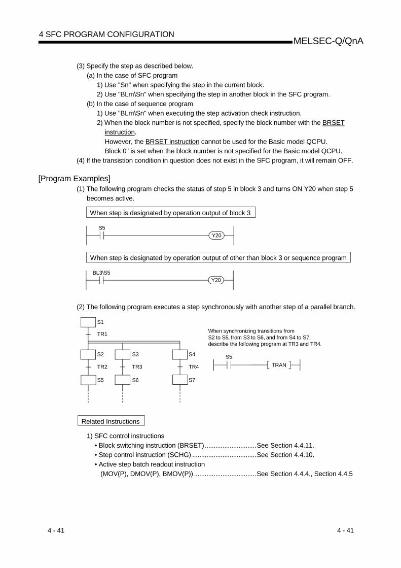
4 - 41 4 - 41
MELSEC-Q/QnA4 SFC PROGRAM CONFIGURATION
(3) Specify the step as described below.(a) In the case of SFC program
1) Use "Sn" when specifying the step in the current block.2) Use "BLm\Sn" when specifying the step in another block in the SFC program.
(b) In the case of sequence program1) Use "BLm\Sn" when executing the step activation check instruction.2) When the block number is not specified, specify the block number with the BRSET
instruction.However, the BRSET instruction cannot be used for the Basic model QCPU.Block 0" is set when the block number is not specified for the Basic model QCPU.
(4) If the transistion condition in question does not exist in the SFC program, it will remain OFF.
[Program Examples](1) The following program checks the status of step 5 in block 3 and turns ON Y20 when step 5
becomes active.
When step is designated by operation output of block 3
S5Y20
When step is designated by operation output of other than block 3 or sequence program
BL3\S5Y20
(2) The following program executes a step synchronously with another step of a parallel branch.
TRAN
S1
TR1
S5
S2
TR2
S3
TR3
S6
S4
TR4
S7
S5
When synchronizing transitions from S2 to S5, from S3 to S6, and from S4 to S7, describe the following program at TR3 and TR4.
Related Instructions
1) SFC control instructions• Block switching instruction (BRSET).............................See Section 4.4.11.• Step control instruction (SCHG) ....................................See Section 4.4.10.• Active step batch readout instruction
(MOV(P), DMOV(P), BMOV(P)) ...................................See Section 4.4.4., Section 4.4.5

4 - 42 4 - 42
MELSEC-Q/QnA4 SFC PROGRAM CONFIGURATION
QnA Q4ARQCPU
PLC CPU Process CPUBasic High Performance
4.4.2 Forced transition check instruction (LD, LDI, AND, ANI, OR, ORI)
Usable Devices Programs Using Instructions Execution Site
Internal Device(System, User)
MELSECNET/10 (H) Direct
J \ SFC Program
Bit Word
FileRegister
RBit Word
SpecialFunctionModule
U \G
IndexZ
ConstantK, H
ExpansionSFC
BLm/TRn
OtherTRn
DataType Sequence
ProgramStep
TransitionCondition
Block StepTransitionCondition
S Devicename
[When step in current block is specified] [When step in another block is specified][When step is specified in sequence program]
TRn “n” is the transition condition No.
TRnLD
BLm\TRn “m” is the block No., “n” is the transition condition No.BLm\TRnLD
TRnTRnLDI
BLm\TRnBLm\TRnLDI
TRnAND BLm\TRnANDTRn BLm\TRn
TRnANI BLm\TRnANITRn BLm\TRn
TRnOR BLm\TRnOR
TRn BLm\TRn
TRnORI BLm\TRnORI
TRn BLm\TRn
[Function](1) Checks whether or not the specified transition condition of the specified block is specified for
forced transition by the forced transition EXECUTE instruction (SET BLm\TRn).
(2) The contact status changes as described below depending on whether the specified transitioncondition is specified for a forced transition or not.
Contact of N/O ContactInstruction
Contact of N/C ContactInstruction
When specified for forcedtransition
ON OFF
When not specified for forcedtransition
OFF ON
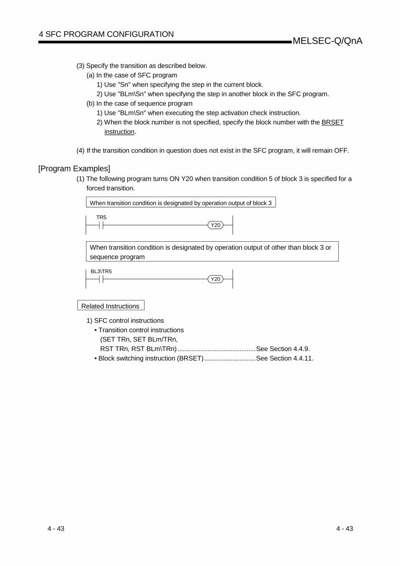
4 - 43 4 - 43
MELSEC-Q/QnA4 SFC PROGRAM CONFIGURATION
(3) Specify the transition as described below.(a) In the case of SFC program
1) Use "Sn" when specifying the step in the current block.2) Use "BLm\Sn" when specifying the step in another block in the SFC program.
(b) In the case of sequence program1) Use "BLm\Sn" when executing the step activation check instruction.2) When the block number is not specified, specify the block number with the BRSET
instruction.
(4) If the transition condition in question does not exist in the SFC program, it will remain OFF.
[Program Examples](1) The following program turns ON Y20 when transition condition 5 of block 3 is specified for a
forced transition.
When transition condition is designated by operation output of block 3
TR5Y20
When transition condition is designated by operation output of other than block 3 orsequence program
BL3\TR5Y20
Related Instructions
1) SFC control instructions• Transition control instructions
(SET TRn, SET BLm/TRn,RST TRn, RST BLm\TRn) ............................................See Section 4.4.9.
• Block switching instruction (BRSET).............................See Section 4.4.11.

4 - 44 4 - 44
MELSEC-Q/QnA4 SFC PROGRAM CONFIGURATION
: First 5 digits of serial No. are 04122 or later
QnA Q4ARQCPU
PLC CPU Process CPUBasic High Performance
4.4.3 Block operation status check instruction (LD, LDI, AND, ANI, OR, ORI)
Usable Devices Programs Using Instructions Execution Site
Internal Device(System, User)
MELSECNET/10 (H) Direct
J \ SFC Program
Bit Word
FileRegister
RBit Word
SpecialFunctionModule
U \G
IndexZ
ConstantK, H
ExpansionSFC
OtherBLm
DataType Sequence
ProgramStep
TransitionCondition
Block StepTransitionCondition
S Devicename
BLm “m” is the block No.LD
BLmLDI
ANDBLm
ANIBLm
OR
BLm
ORI
BLm
[Function](1) Checks whether the specified block is active or inactive.(2) The contact status changes as described below depending on whether the specified block is
active or inactive.
Block StatusContact of N/O Contact
InstructionContact of N/C Contact
Instruction
Active ON OFFInactive OFF ON
(3) The contact is always OFF if the block that does not exist in the SFC program is specified.
REMARK
As the “BLm” device is treated as a virtual device, the contact on the monitor of a peripheraldevice does not turn ON/OFF. If the internal device is ON, the coil instruction is switched ONfor operations.
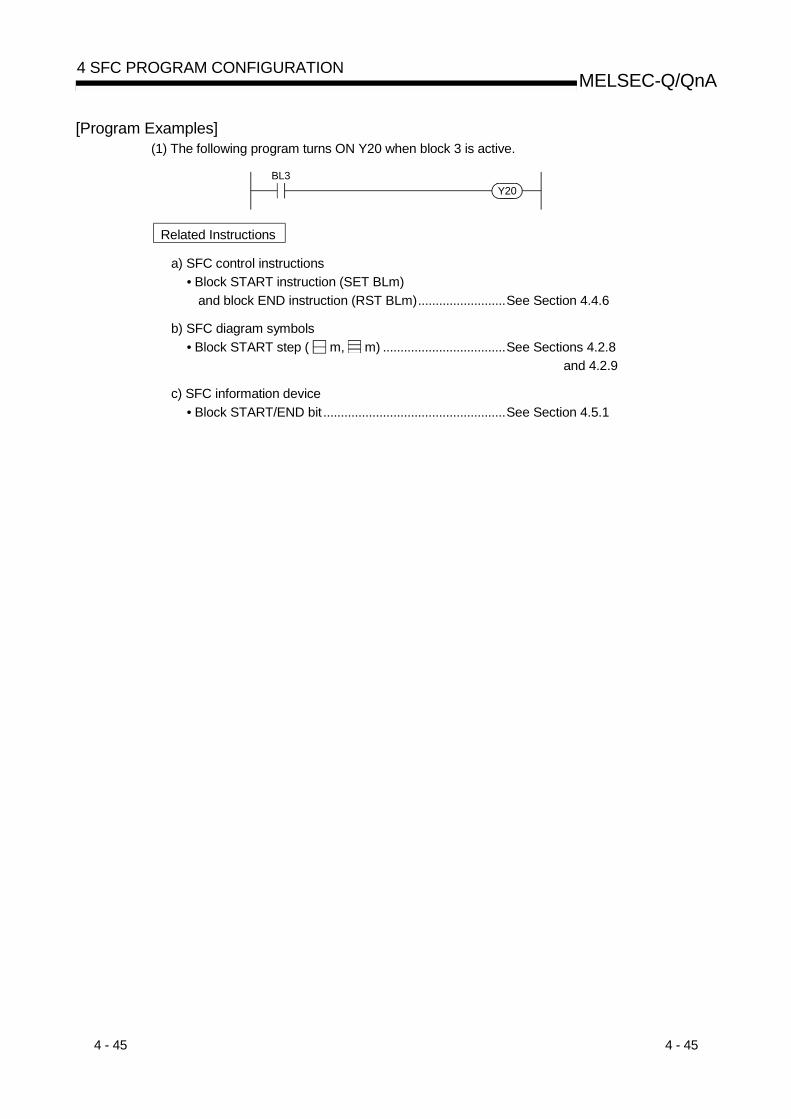
4 - 45 4 - 45
MELSEC-Q/QnA4 SFC PROGRAM CONFIGURATION
[Program Examples](1) The following program turns ON Y20 when block 3 is active.
BL3Y20
Related Instructions
a) SFC control instructions• Block START instruction (SET BLm)
and block END instruction (RST BLm).........................See Section 4.4.6
b) SFC diagram symbols• Block START step ( m, m) ...................................See Sections 4.2.8
and 4.2.9
c) SFC information device• Block START/END bit ....................................................See Section 4.5.1

4 - 46 4 - 46
MELSEC-Q/QnA4 SFC PROGRAM CONFIGURATION
High PerformanceQnA Q4AR
Basic
QCPUPLC CPU Process CPU
: First five digits of serial No. are 04122 or later.
4.4.4 Active step batch readout instructions (MOV, DMOV)
Usable Devices Programs Using Instructions Execution Site
Internal Device(System, User)
MELSECNET/10 (H) Direct
J \ SFC Program
Bit Word
FileRegister
RBit Word
SpecialFunctionModule
U \G
IndexZ
ConstantK, H
ExpansionSFC
BLm\SnOther
DataType Sequence
ProgramStep
TransitionCondition
Block StepTransitionCondition
SD
BIN16/BIN32
: Only step relay (S) can be used
[When step in current block is specified] [When step in another block is specified][When step is specified in sequence program]
“n” is the step No.
MOV(P) S (K4Sn)
DMOV(P) S (K8Sn)
D
D
“m” is the block No, “n” is the step No.
MOV(P) S (BLm\K4Sn)
DMOV(P) S (BLm\K8Sn)
D
D
Readout instruction
[Function](1) Executes a batch readout of the operation statuses (active/inactive) of steps in a specified
block.
(2) The readout results are stored at the “ D ” device as shown below.
b15 b14 b13 b12 b11 b10 b9 b8 b7 b6 b5 b4 b3 b2 b1 b0
0/1 0/1 0/1 0/1 0/1 0/1 0/1 0/1 0/1 0/1 0/1 0/1 0/1 0/1 0/1 0/1
Step designated at SnStep S(n+1)Step S(n+15)
0: Step in question is inactive1: Step in question is active
(3) The bit corresponding to the unassigned step No. (nonexistent step No.) in the read data turnsto "0".When step 5 and step 8 do not exist in the read block, b5 and b8 turn to "0".
b15 b14 b13 b12 b11 b10 b9 b8 b7 b6 b5 b4 b3 b2 b1 b0
S15 S14 S13 S12 S11 S10 S9 None S7 S6 S4 S3 S2 S1 S0
D
None
0/1 0/1 0/1 0/1 0/1 0/1 0/1 0/1 0/1 0/1 0/1 0/1 0/1 0/10 0Corresponding
step No.

4 - 47 4 - 47
MELSEC-Q/QnA4 SFC PROGRAM CONFIGURATION
(4) When the block is not specified, specify the step number with which the read data range doesnot exceed the maximum step No. in the block.(a) If the maximum number of steps is exceeded, data will be undefined.
For example, when the last step of the block to be read is step 10 (S10), data in b11 to 15will be undefined.
b15 b14 b13 b12 b11 b10 b9 b8 b7 b6 b5 b4 b3 b2 b1 b0
S10 S9 S8 S7 S6 S4 S3 S2 S1 S0
D
S5
0/1 0/1 0/1 0/1 0/1 0/1 0/1 0/1 0/1 0/1 0/1 0/1 0/1 0/1
Correspondingstep No.
0/1 0/1
S4 S3 S2 S1 S0
Undefined data Information of corresponding block
(b) When the block has been specified, "0" is stored into the remaining bits.When block 1 is specified, "0" is stored into B11 - 15 if the last step of block 1 is step 10(S10).
b15 b14 b13 b12 b11 b10 b9 b8 b7 b6 b5 b4 b3 b2 b1 b0
S10 S9 S8 S7 S6 S4 S3 S2 S1 S0
D
S5
0/1 0/1 0/1 0/1 0/1 0/1 0/1 0/1 0/1 0/1 0/1 0/1 0/1 0/1
Correspondingstep No.
0/1 0/1
0 is stored into all bits. Information of block 1
(5) In the activation step batch read instruction, do not specify a nonexistent block/step.An error will not occur if a nonexistent block/step is specified.However, the read data are undefined.
[Operation Error]• No error occurs.

4 - 48 4 - 48
MELSEC-Q/QnA4 SFC PROGRAM CONFIGURATION
[Program Examples](1) The following program reads 32 active steps, starting from step 0 of block 3, to D0 and D1
when X0 turns ON.
When step is designated by operation output of block 3
X0D0K8S0DMOVP
When step is designated by operation output of other than block 3 or sequence program
X0D0BL3\K8S0DMOVP
b15 b14 b13 b12 b11 b10 b9 b8 b7 b6 b5 b4 b3 b2 b1 b0
S15 S14 S13 S12 S11 S10 S9 S8 S7 S6 S5 S4 S3 S2 S1 S0
D0
S31 S30 S29 S28 S27 S26 S25 S24 S23 S22 S21 S20 S19 S18 S17 S16
D1 Step Nos.
Related Instructions
1) SFC control instructions• Block switching instruction (BRSET).............................See Section 4.4.11.• Step operation status check
instruction (LD, LDI, AND, ANI, OR, ORI)....................See Section 4.4.1.• Active step batch readout
instruction (BMOV)........................................................See Section 4.4.5.

4 - 49 4 - 49
MELSEC-Q/QnA4 SFC PROGRAM CONFIGURATION
High PerformanceQnA Q4AR
Basic
QCPUPLC CPU Process CPU
: First five digits of serial No. are 04122 or later.
4.4.5 Active step batch readout (BMOV)
Usable Devices Programs Using Instructions Execution Site
Internal Device(System, User)
MELSECNET/10 (H) Direct
J \ SFC Program
Bit Word
FileRegister
RBit Word
SpecialFunctionModule
U \G
IndexZ
ConstantK, H
ExpansionSFC
BLm\Sn
OtherSn
DataType Sequence
ProgramStep
TransitionCondition
Block StepTransitionCondition
SDn
BIN16
: Only step relay (S) can be used
“n” is the step No.
BMOV(P) S (K4Sn) D
“m” is the block No.
BMOV(P) S (BLm\K4Sn) D
Number of readouts
n n
[Function](1) A batch readout (designated number of words) of step operation statuses is executed at the
specified block.
(2) The readout results are stored at the “D” device as shown below.
b50/1 0/1 0/1 0/1 0/1 0/1 0/1 0/1 0/1 0/1 0/1 0/1 0/1 0/1 0/1 0/1b15 b14 b13 b12 b11 b10 b9 b8 b7 b6 b4 b3 b2 b1 b0
Step designated at Sn
Step S(n+1)Step S(n+15)
D
0: Step in question is inactive1: Step in question is active
0/1 0/1 0/1 0/1 0/1 0/1 0/1 0/1 0/1 0/1 0/1 0/1 0/1 0/1 0/1 0/1
Step S(n+16)Step S(n+31)
D +1
0/1 0/1 0/1 0/1 0/1 0/1 0/1 0/1 0/1 0/1 0/1 0/1 0/1 0/1 0/1 0/1
Step S(n+ (A 16))Step S(n+ (A 16 + 15))
D +A
(3) The bit corresponding to the unassigned step No. (nonexistent step No.) in the read data turnsto "0".

4 - 50 4 - 50
MELSEC-Q/QnA4 SFC PROGRAM CONFIGURATION
(4) If the read data range exceeds the maximum step No. in the block, the data of the next blockNo. are read.When there are no blocks in and after the block to be read, "0" is stored into the remaining bits.Example:When "BMOV BL1\S2 D0 K2" is executed in the following case,• Block 1 : The maximum step No. is 10 (S10) and step 5 (S5) and step 8 (S8) do not
exist• Block 2 : The maximum step No. is 12 (S12) and step 3 (S3) does not exist• Block 3 and later: Do not existdata are stored as shown below.
b15 b14 b13 b12 b11 b10 b9 b8 b7 b6 b5 b4 b3 b2 b1 b0
S10 S9 None S7 None S4 S3 S2
D0
S5
0/1 0/1 0/1 0/1 0/1 0/1 0/1 0/1 0/1 0/1 0/1 0/1 0/1 0/1
Correspondingstep No.
0/1 0/1
Information of block 2 Information of block 1
S6 S4 None S2 S1 S0S5
b15 b14 b13 b12 b11 b10 b9 b8 b7 b6 b5 b4 b3 b2 b1 b0
S10 S9 S8 S7
D1 0/1 0/1 0/1 0/1 0/1 0/1Corresponding
step No.
0/1
Information of block 2All turn to 0s since blocks do not exist.
S12 S11
0 0 0 0 0 0 0 0 0
(5) If there is a nonexistent block in the data to be read, the nonexistent block is omitted and thedata of the next existing block are read.Example:When "BMOV BL1\S2 D0 K2" is executed in the following case,• Block 1: The maximum step No. is 10 (S10)• Block 2: Nonexistent• Block 3: The maximum step No. is 12 (S12)• Block 4: The maximum step No. is 15 (S15)data are stored as shown below.
b15 b14 b13 b12 b11 b10 b9 b8 b7 b6 b5 b4 b3 b2 b1 b0
S10 S9 S6 S7 S4 S4 S3 S2
D0
S5
0/1 0/1 0/1 0/1 0/1 0/1 0/1 0/1 0/1 0/1 0/1 0/1 0/1 0/1
Correspondingstep No.
0/1 0/1
Information of block 3 Information of block 1
S6 S4 S3 S2 S1 S0S5
b15 b14 b13 b12 b11 b10 b9 b8 b7 b6 b5 b4 b3 b2 b1 b0
S10 S9 S8 S7
D1 0/1 0/1 0/1 0/1 0/1 0/1Corresponding
step No.
0/1
Information of block 3Information of block 4
S12 S11S6 S4 S3 S2 S1 S0S5S9 S8 S7
0/1 0/1 0/1 0/1 0/1 0/1 0/1 0/10/1
(6) In the activation step batch read instruction, do not specify a nonexistent block/step.An error will not occur if a nonexistent block/step is specified.However, the read data are undefined.
[Operation Error]• When the step relay (S) range is exceeded ......................Error No. 4101

4 - 51 4 - 51
MELSEC-Q/QnA4 SFC PROGRAM CONFIGURATION
[Program Examples](1) The following program reads the active step status of 48 steps (3 words), starting from step 0
of block 3, to D0 - D2 when X0 turns ON.
When step is designated by operation output of block 3
X0K3K4S0BMOVP D0
When step is designated by operation output of other than block 3 or sequence program
X0K3BL3\S0BMOVP D0
b15 b14 b13 b12 b11 b10 b9 b8 b7 b6 b5 b4 b3 b2 b1 b0
S15 S14 S13 S12 S11 S10 S9 S8 S7 S6 S5 S4 S3 S2 S1 S0D0
S31 S30 S29 S28 S27 S26 S25 S24 S23 S22 S21 S20 S19 S18 S17 S16D1 Step Nos.
S47 S46 S45 S44 S43 S42 S41 S40 S39 S38 S37 S36 S35 S34 S33 S32D2
Related Instructions
1) SFC control instructions• Block switching instruction (BRSET).............................See Section 4.4.11• Step operation status check
instruction (LD, LDI, AND, ANI, OR, ORI)....................See Section 4.4.1• Active step batch readout
instruction (MOV, DMOV) .............................................See Section 4.4.4

4 - 52 4 - 52
MELSEC-Q/QnA4 SFC PROGRAM CONFIGURATION
High PerformanceQnA Q4AR
Basic
QCPUPLC CPU Process CPU
: First five digits of serial No. are 04122 or later.
4.4.6 Block START & END instructions (SET, RST)
Usable Devices Programs Using Instructions Execution Site
Internal Device(System, User)
MELSECNET/10 (H) Direct
J \ SFC Program
Bit Word
FileRegister
RBit Word
SpecialFunctionModule
U \G
IndexZ
ConstantK, H
ExpansionSFC
BLm\SnBLm\TRn
OtherBLm
DataType Sequence
ProgramStep
TransitionCondition
Block StepTransitionCondition
D Devicename
“m” is the block No.
SET D (BLm) RST D (BLm)
[Function](1) Block START instruction (SET BLm)
(a) A specified block is forcibly activated independently and is executed from its initial step.When there are multiple initial steps, all initial steps become active.When the bock START/END bit of the SFC information devices has been set, thecorresponding bit device changes from OFF to ON.
(b) If the specified block is already active when this instruction is executed, the instruction willbe ignored (equivalent to the NOP instruction), and processing will continue.
(2) Block END instruction (RST BLm)(a) A specified block is forcibly deactivated independently.
When there are active steps, all are deactivated and the coil outputs are turned OFF.When the bock START/END bit of the SFC information devices has been set, thecorresponding bit device changes from ON to OFF.
(b) If the specified block is already inactive when this instruction is executed, the instruction willbe ignored (equivalent to the NOP instruction) and processing will continue.
[Operation Error]• Error No. 4621 occurs when the specified block does not exist or when the SFC program is in
the standby status.
[Program Examples](1) When X1 switches ON, the following program forcibly activates block1. When X2 switches ON,
it ends and forcibly deactivates block1.X1
SET BL1
X2RST BL1
Related Instructions
a) SFC diagram symbols• Block START step ( m, m ) ....................................See Sections 4.2.8 and 4.2.9.
b) SFC information device• Block START/END bit ....................................................See Section 4.5.1.
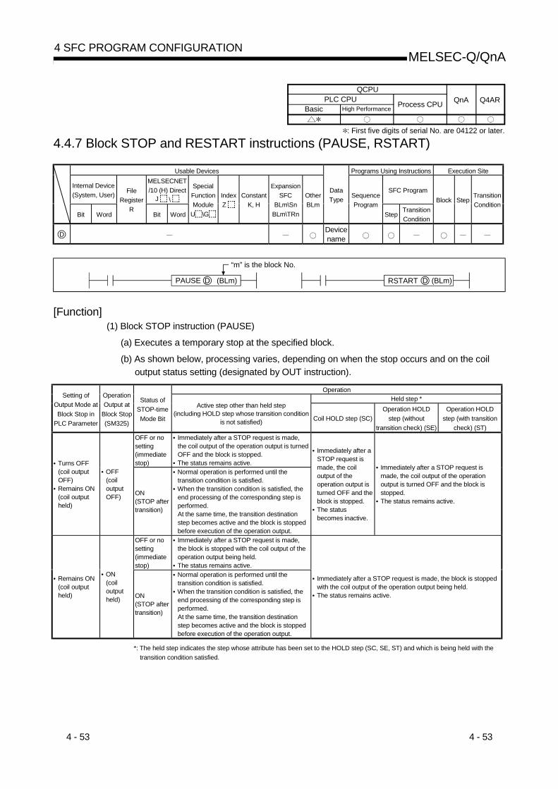
4 - 53 4 - 53
MELSEC-Q/QnA4 SFC PROGRAM CONFIGURATION
High PerformanceQnA Q4AR
Basic
QCPUPLC CPU Process CPU
: First five digits of serial No. are 04122 or later.
4.4.7 Block STOP and RESTART instructions (PAUSE, RSTART)
Usable Devices Programs Using Instructions Execution Site
Internal Device(System, User)
MELSECNET/10 (H) Direct
J \ SFC Program
Bit Word
FileRegister
RBit Word
SpecialFunctionModule
U \G
IndexZ
ConstantK, H
ExpansionSFC
BLm\SnBLm\TRn
OtherBLm
DataType Sequence
ProgramStep
TransitionCondition
Block StepTransitionCondition
D Devicename
“m” is the block No.
PAUSE D (BLm) RSTART D (BLm)
[Function](1) Block STOP instruction (PAUSE)
(a) Executes a temporary stop at the specified block.
(b) As shown below, processing varies, depending on when the stop occurs and on the coiloutput status setting (designated by OUT instruction).
OperationHeld step *Setting of
Output Mode atBlock Stop in
PLC Parameter
OperationOutput at
Block Stop(SM325)
Status ofSTOP-timeMode Bit
Active step other than held step(including HOLD step whose transition condition
is not satisfied) Coil HOLD step (SC)Operation HOLD
step (withouttransition check) (SE)
Operation HOLDstep (with transition
check) (ST)OFF or nosetting(immediatestop)
• Immediately after a STOP request is made,the coil output of the operation output is turnedOFF and the block is stopped.
• The status remains active.• Turns OFF(coil outputOFF)
• Remains ON(coil outputheld)
• OFF(coiloutputOFF) ON
(STOP aftertransition)
• Normal operation is performed until thetransition condition is satisfied.
• When the transition condition is satisfied, theend processing of the corresponding step isperformed.At the same time, the transition destinationstep becomes active and the block is stoppedbefore execution of the operation output.
• Immediately after aSTOP request ismade, the coiloutput of theoperation output isturned OFF and theblock is stopped.
• The statusbecomes inactive.
• Immediately after a STOP request ismade, the coil output of the operationoutput is turned OFF and the block isstopped.
• The status remains active.
OFF or nosetting(immediatestop)
• Immediately after a STOP request is made,the block is stopped with the coil output of theoperation output being held.
• The status remains active.
• Remains ON(coil outputheld)
• ON(coiloutputheld) ON
(STOP aftertransition)
• Normal operation is performed until thetransition condition is satisfied.
• When the transition condition is satisfied, theend processing of the corresponding step isperformed.At the same time, the transition destinationstep becomes active and the block is stoppedbefore execution of the operation output.
• Immediately after a STOP request is made, the block is stoppedwith the coil output of the operation output being held.
• The status remains active.
*: The held step indicates the step whose attribute has been set to the HOLD step (SC, SE, ST) and which is being held with thetransition condition satisfied.

4 - 54 4 - 54
MELSEC-Q/QnA4 SFC PROGRAM CONFIGURATION
POINTSSM325 is turned ON/OFF by the system according to the output mode setting at parameterblock STOP when the CPU module switches from STOP to RUN.
Output Mode Setting at Parameter Block STOP SM325
Turns OFF (coil output OFF) OFFRemain ON (coil output held) ON
However, by turning ON/OFF SM325 in the user program, the output mode at block STOP canbe changed independently of the parameter setting.
(c) The STOP/RESTART bit switches ON when the SFC control “block STOP” instruction(PAUSE BLm) is executed.
(2) Block RESTART instruction (RSTART)
(a) The block in question is restarted from the step where a STOP occurred.An “operation HOLD status” step (with transition check or without transition check) whichhas been stopped will be restarted with the operation HOLD status in effect.A “coil output HOLD” step cannot be restarted after being stopped as it becomesdeactivated at that time.
(b) Depending on the ON/OFF status of the "block STOP-time operation output flag (SM325)",the operations of the PLS instruction and P instruction after block STOP cancellationchange.• When SM325 is ON (coil output held)..........................Not executed• When SM325 is OFF (coil output OFF) .......................Executed again
(c) When the block STOP/RESTART bit of the SFC information devices has been set, theblock STOP/RESTART bit also turns OFF.
[Operation Error]• Error No. 4621 occurs when the specified block does not exist or when the SFC program is
in the standby status.
[Program Examples](1) Block 1 is stopped when X1 switches ON, and is restarted when X2 switches ON.
PAUSEX1
BL1
RSTARTX2
BL1
Related Instructions
1) SFC information device• Block STOP/RESTART bit.............................................See Section 4.5.3.

4 - 55 4 - 55
MELSEC-Q/QnA4 SFC PROGRAM CONFIGURATION
High PerformanceQnA Q4AR
Basic
QCPUPLC CPU Process CPU
: First five digits of serial No. are 04122 or later.
4.4.8 Step START and END instructions (SET, RST)
Usable Devices Programs Using Instructions Execution Site
Internal Device(System, User)
MELSECNET/10 (H) Direct
J \ SFC Program
Bit Word
FileRegister
RBit Word
SpecialFunctionModule
U \G
IndexZ
ConstantK, H
ExpansionSFC
BLm\Sn
OtherSn
DataType Sequence
ProgramStep
TransitionCondition
Block StepTransitionCondition
D Devicename
: Only step relay (S) can be used
“n” is the step No.
SET D (Sn)
“m” is the block No.
SET D (BLm\Sn)
RST D (Sn)
RST D (BLm\Sn)
[Function](1) Step START instruction (SET)
(a) A specified step at a specified block is activated forcibly. Operation at the block in questionvaries as follows, depending on whether the block is active or inactive.1) When the specified block is inactive:
The specified block is activated when the instruction is executed, and processing startsfrom the specified step.Processing is performed as shown below when step 1 in block 1 is started in thesequence program.
S0
S2: Inactive
S1: Inactive
Block 1: Inactive Block 1: Inactive to active
When step 1 (S1)is started
S0
S2: Inactive
S1: Inactive to active (processing starts from S1)
When the block START/END bit of the SFC information devices has been set, thecorresponding bit device changes from OFF to ON.

4 - 56 4 - 56
MELSEC-Q/QnA4 SFC PROGRAM CONFIGURATION
2) When the specified block is active:If the step is already active when the SET instruction is executed, the step will remainactive and processing will continue, with another step being designated as active.(Multiple step activation, follow-up function.)Processing is performed as shown below when step 1 in block 1 is started in thesequence program.
S0
S2: Active
S1: Inactive
Block 1: Active Block 1: Active
When step 1 (S1)is started
S0
S2: Active
S1: Inactive to active
Multiple steps active(Follow-up function)
(b) When multiple initial steps exist, an initial step selection START will occur when a givenstep is specified and activated.
(c) When designating a step located in a parallel branch, all the parallel steps should beactivated. An inactive parallel branch ladder at such a time will prevent the parallel couplingcondition from being satisfied.
(d) If a specified step is already active when this instruction is executed, the instruction will beignored (equivalent to the NOP instruction), and processing will continue.To hold a specified step with the HOLD step, see "Transition to HOLD step by doubleSTART" in Section 4.7.6.
(e) When the operation output is used to start the step, do not specify the current step numberas the specified step number.If the current step is designated as the specified step number, normal operation will not beperformed.
S0
S2
S1MO
S1SET
(f) Specify the step as described below.1) In the case of SFC program
• Use "Sn" when specifying the step in the current block.• Use "BLm\Sn" when specifying the step in another block.
2) In the case of sequence program• Use "BLm\Sn" when executing the step START instruction in the sequence program.• When the block number is not specified, specify the block number with the BRSET
instruction.However, the BRSET instruction cannot be used for the Basic model QCPU.Block 0" is set when the block number is not specified for the Basic model QCPU.

4 - 57 4 - 57
MELSEC-Q/QnA4 SFC PROGRAM CONFIGURATION
(2) Step END instruction (RST)
(a) A specified step at a specified block is forcibly deactivated. “Coil HOLD” and “operationHOLD” steps are subject to this instruction.
(b) When the number of active steps in the corresponding block reaches 0 due to theexecution of this instruction, END step processing is performed and the block becomesinactive.When the bock START/END bit of the SFC information devices has been set, thecorresponding bit device changes from ON to OFF.
(c) If the RST instruction is executed at a step located in a parallel branch, the parallel couplingcondition will remain unsatisfied.
(d) If a specified step is already inactive when this instruction is executed, the instruction willbe ignored (equivalent to the NOP instruction).
(e) When the operation output is used to end the step, do not specify the current step as thespecified step number.If the current step is designated as the specified step number, normal operation will not beperformed.
S0
S2
S1MO
S1RST
(f) Specify the step as described below.1) In the case of SFC program
• Use "Sn" when specifying the step in the current block.• Use "BLm\Sn" when specifying the step in another block.
2) In the case of sequence program• Use "BLm\Sn" when executing the step END instruction in the sequence program.• When the block number is not specified, specify the block number with the BRSET
instruction.However, the BRSET instruction cannot be used for the Basic model QCPU.Block 0" is set when the block number is not specified for the Basic model QCPU.
[Operation Error]• When no specified step is present or the SFC program is in standby mode: Error No.4631

4 - 58 4 - 58
MELSEC-Q/QnA4 SFC PROGRAM CONFIGURATION
[Program Examples](1) When X1 switches ON, the following program will select and start step 2 of block 1 which
contains multiple initial steps.
When step is designated by operation outputof block 1
X1SET S2
When step is designated by operationoutput of other than block 3 or sequenceprogram
S0 S1 S2
S4 S5
S6
S3
(Block 1)
X1SET BL1\S2
(2) The following program deactivates held step 5 when step 10 is activated.
RST S5
S5
S6
S10
SE

4 - 59 4 - 59
MELSEC-Q/QnA4 SFC PROGRAM CONFIGURATION
High PerformanceQnA Q4AR
Basic
QCPUPLC CPU Process CPU
4.4.9 Forced transition EXECUTE & CANCEL instructions (SET, RST)
Usable Devices Programs Using Instructions Execution Site
Internal Device(System, User)
MELSECNET/10 (H) Direct
J \ SFC Program
Bit Word
FileRegister
RBit Word
SpecialFunctionModule
U \G
IndexZ
ConstantK, H
ExpansionSFC
BLm\TRn
OtherTRn
DataType Sequence
ProgramStep
TransitionCondition
Block StepTransitionCondition
D Devicename
“n” is the step No.
SET D (TRn)
“m” is the block No.
SET D (BLm\TRn)
RST D (TRn)
RST D (BLm\TRn)
[Function](1) Forced transition EXECUTE instruction (SET)
(a) A specified transition condition in a specified block is forcibly satisfied, and an unconditionaltransition is executed at the step which precedes the condition.
User designated transition condition
Tran
Continuous transition preventer SM324
Always ONLadder resulting from execution of SET instruction
(b) After execution of the instruction, the forced transition status remains effective until a resetinstruction is executed.
(2) Forced transition CANCEL instruction (RST)(a) Cancels the forced transition setting (designated by SET instruction) at a transition
condition, and restores the transition condition ladder created by the user.
(3) Specify the transition condition as described below.(a) In the case of SFC program
• Use "TRn" when specifying the transition condition in the current block.• Use "BLm \TRn" when specifying the transition condition in another block.
(b) In the case of sequence program• Use "BLm \TRn" when executing the forced transition EXECUTE/CANCEL instruction in
the sequence program.• When the block number is not specified, specify the block number with the BRSET
instruction.However, the BRSET instruction cannot be used for the Basic model QCPU."Block 0" is set when the block nomber is not specified for the Basic model QCPU.

4 - 60 4 - 60
MELSEC-Q/QnA4 SFC PROGRAM CONFIGURATION
[Operation Error]• When the specified transition condition does not exist or the SFC program is in a wait state
........................................................................................................................... Error No. 4631
[Program Examples](1) When X1 switches ON, the following program executes a forced transition at transition
condition 1 of block 1. The forced transition setting is canceled when X2 switches ON.
When step is designated by operation output of block 1
X1SET TR1
X2RST TR1
When step is designated by operation output of other than block 1 or sequence program
X1SET BL1\TR1
X2RST BL1\TR1

4 - 61 4 - 61
MELSEC-Q/QnA4 SFC PROGRAM CONFIGURATION
High PerformanceQnA Q4AR
Basic
QCPUPLC CPU Process CPU
4.4.10 Active step change instruction (SCHG)
Usable Devices Programs Using Instructions Execution Site
Internal Device(System, User)
MELSECNET/10 (H) Direct
J \ SFC Program
Bit Word
FileRegister
RBit Word
SpecialFunctionModule
U \G
IndexZ
ConstantExpansion
SFCOther
DataType Sequence
ProgramStep
TransitionCondition
Block StepTransitionCondition
D BIN16
SCHG D
[Function](1) Deactivates the step that executed an instruction, and forcibly activates the specified step (set
with the device designated by D ) in the same block.
(2) When the destination step is already active, the step that executed the SCHG instruction isdeactivated and the destination step continues processing as-is.
(3) The step where this instruction is executed is deactivated when processing proceeds to thetransition condition status check following the completion of that step's program operation.
(4) This instruction can only be used at SFC program steps.
[Operation Error]• Error No.4631 occurs when the specified destination step does not exist.• Error No.4001 occurs when this instruction is used at a sequence program other than an
SFC program (error is activated on switching from STOP to RUN).
[Program Examples](1) When X1 switches ON, the following program deactivates step 5, and activates step 6.
X1SCHG K6
S5 S6

4 - 62 4 - 62
MELSEC-Q/QnA4 SFC PROGRAM CONFIGURATION
High PerformanceQnA Q4AR
Basic
QCPUPLC CPU Process CPU
4.4.11 Block switching instruction (BRSET)
Usable Devices Programs Using Instructions Execution Site
Internal Device(System, User)
MELSECNET/10 (H) Direct
J \ SFC Program
Bit Word
FileRegister
RBit Word
SpecialFunctionModule
U \G
IndexZ
ConstantExpansion
SFCOther
DataType Sequence
ProgramStep
TransitionCondition
Block StepTransitionCondition
S BIN16
BRSET S
[Function](1) Switches the target block number of the SFC control instruction that specifies only a step (Sn)
and transition condition (TRn) to the number set for the device designated by S .
(2) Although “BLm\Sn” or “BLm/TRn” may be used as the instruction device when designating thedestination block number, only a constant (K, H) may be designated at the “m” of “BLm”,thereby fixing the designation destination.When block switching is executed by this BRSET instruction, a word device can be used forindirect designation, index modification, etc.
(3) The effective operation range when block switching occurs (by BRSET instruction) variesaccording to the program being run at the time, as shown below.1) When this instruction is executed in a sequence program, target block switching is valid
from instruction execution to SFC execution.At the next scan, the target block is block 0 as the default until the instruction is executedagain.

4 - 63 4 - 63
MELSEC-Q/QnA4 SFC PROGRAM CONFIGURATION
2) If the BRSET instruction is executed at an SFC program, block switching will be effectiveonly for the step currently being executed.Even if the step in question is the same step, the BRSET instruction must be executed ateach block where the Sn and TRn instructions are used.Moreover, within a single step, block switching will be effective from the point where theBRSET instruction is executed to that step's processing END point.When processing is repeated at the next scan following the processing END for that step,the block in question will be designated as the “current block” until the point when theBRSET instruction is executed again.
Block specified by instructionBlock 0
END/0A
Block specified by instruction
ENDB
Block specified by instructionCurrent block
Block “n”
Block specified by instructionCurrent block
ENDBlock “n+1”0SFC programSequence program Sequence program
(Repeated)
1 scanThe block No. (m) designated by BLm\Sn or BLm\TRn becomes valid regardless of whether this instruction is executed or not.
When multiple steps are active at parallel branch, etc., only the stepwhere the instruction was executed will be valid.When it is desired to designate blocks at multiple steps, the instruction must be executed at each step.
Sn/TRn destination block
Execution Program
Inst
ruct
ion
exec
uted
Inst
ruct
ion
exec
uted
Inst
ruct
ion
exec
uted
Inst
ruct
ion
exec
uted
END processing not performed
END processing not performed
[Operation Error]• Error No. 4621 occurs when the specified block does not exist or when the SFC program is in
the standby status.
[Program Examples](1) When X1 switches ON, the following program switches the Sn or TRn block number to the
block number stored at the D0 data register.Condition
X1BRSET D0
MOV Kn D0
(2) When X2 switches ON, the following program switches the Sn or TRn block number accordingto the constant at the Z1 index register.
X2BRSET K0Z1

4 - 64 4 - 64
MELSEC-Q/QnA4 SFC PROGRAM CONFIGURATION
4.5 SFC Information Devices
This section explains the SFC information devices set in each block. Table 4.2 indicates the SFCinformation device types and usable devices.
Table 4.3 SFC Information Device ListCPU Module Type
SFC InformationDevice Function Outline
UsableDevice
BasicmodelQCPU
High Performancemodel QCPU, Process
CPU, QnACPU
BlockSTART/END bit
• Device designed to forcibly start or forcibly end thespecified block by a sequence program or the testoperation of the peripheral device.
• Can also be used to confirm the active status of thespecified block.
Step transition bit• Device that checks whether or not a step transition
occurred in the corresponding scan in the specifiedblock.
Block STOP/RESTART bit
• Device designed to stop temporarily or restart thecorresponding block that is active.
Block STOP modebit
• Device used to specify whether all steps will beimmediately stopped or the block will be stopped afterthe transition of the corresponding step when the block isstopped temporarily.
Continuoustransition bit
• Device used to specify whether the operation output ofthe next step will be executed within the same scan ornot when the transition condition is satisfied.
Y, M, L,F, V, B
"Number of activesteps" register
• Device that stores the number of steps currently active inthe specified block.
D, W,R, ZR
: Usable
When using the SFC information devices, set them in "Block information setting" at theinput (editing) of the SFC diagram. When the SFC information devices are not used,they need not be set.
POINTSThe following cannot be specified for the SFC information devices.• Indirect designation (@)• Digit designation (K)• Index qualification (Z)• Word device bit designation (.)

4 - 65 4 - 65
MELSEC-Q/QnA4 SFC PROGRAM CONFIGURATION
4.5.1 Block START/END bit
The block START/END bit is used to confirm the active status of the specified block by asequence program or the test operation of the peripheral device.It can also be used as a device to forcibly start or forcibly end the specified block.
(1) Operation of block START/END bit(a) The block START/END bit turns ON when the corresponding block starts.
The block START/END bit remains ON while the corresponding block is active.(b) The block START/END bit turns OFF when the corresponding block becomes inactive.
The block START/END bit remains OFF while the corresponding block is inactive.Block 0
S0
t0
S1
t1
S2 B1
t2
Block 1
S0
t0
S1
t1
S2
t2
"Block START/END bit" of block 1: M0
M0 ON
OFF
1) 2)1)
2)
(2) When the corresponding block is inactive, it can be started independently by forcibly turningON the block START/END bit.While the corresponding block is active, the processing of the corresponding block can beforcibly ended by forcibly turning OFF the block START/END bit.The block START/END bit can also be turned ON/OFF in the test mode of the peripheraldevice.
(3) When a forced OFF is executed by the block START/END bit, and the block in questionbecomes inactive, processing will occur as follows:(a) Execution of the block in question will stop together with all outputs from the step which
was being executed. (Devices switched ON by the SET instruction will not switch OFF.)(b) If another block is being started by the block START step in the corresponding block, the
corresponding block stops.However, the start destination block remains active and continues processing.To also end the start destination block simultaneously, the block START/END bit of thestart destination must also be turned OFF.

4 - 66 4 - 66
MELSEC-Q/QnA4 SFC PROGRAM CONFIGURATION
(4) A block which has been forcibly deactivated is restarted as shown below.
Relevant Block Restart StatusWhen the START condition of block 0 is"Auto START ON" in the SFC setting of thePLC parameter dialog box.
Operation is restarted from the initialstep following END step processing.
Block 0When the START condition of block 0 is"Auto START OFF" in the SFC setting of thePLC parameter dialog box.
Other than block 0
The block is deactivated after ENDstep processing, and processing isrestarted from the initial step whenanother START request occurs forthat block.
Program exampleUse the contact of the "block START/END bit" when a transition occurs after block 1 ends.
M0TRAN
Block 0
S0
t0
S1
t1
S2BL1
t2
Block 1
S0
t0
S1BL2
t1
S2
t2
Block 2
S0
t0
S1
t1
S2
t2
Using "BL1" instead of "block STAT/END bit" as contact, the same operation can be performed.
Related Instructions
1) SFC control instructions• Block START instruction (SET BLm), block END instruction
(RST BLm) ....................................................................See Section 4.4.6.2) SFC diagram symbols
• Block START step ( m, m) ...................................See Sections 4.2.8.and 4.2.9.

4 - 67 4 - 67
MELSEC-Q/QnA4 SFC PROGRAM CONFIGURATION
4.5.2 Step transition bit
The step transition bit is designed to check whether the transition condition of the step inexecution has been satisfied or not.
(1) After the operation output at each step is completed, the step transition bit automaticallyswitches ON when the transition condition (for transition to the next step) is satisfied.
(2) A transition bit which is ON will automatically switch OFF when processing of the block inquestion occurs again.
Example: Step transition bit = M1
(Transition condition 0)
S0
S1
S2
S3
Block “n”
(Transition condition 1)
(Transition condition 2)
“M1”ON
OFF
Oth
er p
rogr
am e
xecu
ted
Oth
er p
rogr
am e
xecu
ted
Oth
er p
rogr
am e
xecu
ted
Step
0Tr
ansi
tion
cond
ition
0 s
atis
fied
Step
1Tr
ansi
tion
cond
ition
1 u
nsat
isfie
d
Step
1Tr
ansi
tion
cond
ition
1 s
atis
fied
Step
2Tr
ansi
tion
cond
ition
2 u
nsat
isfie
d
(3) If a continuous transition is designated (continuous transition bit ON), the transition bit willremain ON during the next step's operation output after the transition condition is satisfied.It will also remain ON following the execution of multiple steps, even if the transition conditionis unsatisfied.In these cases, the transition bit will switch OFF when block execution occurs at the next scan.Example: Step transition bit = M1
“M1”ON
OFF
Oth
er p
rogr
am e
xecu
ted
Step
1
Step
0Tr
ansi
tion
cond
ition
0 s
atis
fied
Step
1Tr
ansi
tion
cond
ition
1 u
nsat
isfie
d

4 - 68 4 - 68
MELSEC-Q/QnA4 SFC PROGRAM CONFIGURATION
(4) At active parallel branch steps, the transition bit will switch ON when any of the transitionconditions are satisfied.
“M1”Tran
Sn
TranTran
S(n+1) S(n+2)
Oth
er p
rogr
am e
xecu
ted
Step
“n”
Step
“n”
Tran
sitio
n co
nditi
on u
nsat
isfie
dSt
ep “n
+1”
Tran
sitio
n co
nditi
on s
atis
fied
Step
“n+2
”Tr
ansi
tion
cond
ition
uns
atis
fied

4 - 69 4 - 69
MELSEC-Q/QnA4 SFC PROGRAM CONFIGURATION
4.5.3 Block STOP/RESTART bit
The block STOP/RESTART bit is used to temporarily stop processing while the correspondingblock is active.
(1) When the designated block STOP/RESTART bit is switched ON by the sequence program orperipheral device, processing will be stopped at the current step of the block in question.If a START status is in effect at another block, the STOP will still occur, but the STARTdestination block will remain active and processing will continue.To stop the START destination block at the same time, the START destination's blockSTOP/RESTART bit must also be switched OFF.
(2) When a block is stopped by switching the block STOP/RESTART bit ON, the STOP timing willbe as shown below.
OperationHeld step *
Setting ofOutput Mode atBlock Stop in
PLC Parameter
OperationOutput at
Block Stop(SM325)
Status ofSTOP-timeMode Bit
Active step other than held step(including HOLD step whose transition condition
is not satisfied) Coil HOLD step (SC)Operation HOLD
step (withouttransition check) (SE)
Operation HOLDstep (with transition
check) (ST)OFF or nosetting(immediatestop)
• Immediately after a STOP request is made,the coil output of the operation output is turnedOFF and the block is stopped.
• The status remains active.• Turns OFF(coil outputOFF)
• Remains ON(coil outputheld)
• OFF(coiloutputOFF) ON
(STOP aftertransition)
• Normal operation is performed until thetransition condition is satisfied.
• When the transition condition is satisfied, theend processing of the corresponding step isperformed.At the same time, the transition destinationstep becomes active and the block stopsimmediately.
• Immediately after aSTOP request ismade, the coiloutput of theoperation output isturned OFF and theblock is stopped.
• The statusbecomes inactive.
• Immediately after a STOP request ismade, the coil output of the operationoutput is turned OFF and the block isstopped.
• The status remains active.
OFF or nosetting(immediatestop)
• Immediately after a STOP request is made,the block is stopped with the coil output of theoperation output being held.
• The status remains active.
• Remains ON(coil outputheld)
• ON(coiloutputheld) ON
(STOP aftertransition)
• Normal operation is performed until thetransition condition is satisfied.
• When the transition condition is satisfied, theend processing of the corresponding step isperformed.At the same time, the transition destinationstep becomes active and the block stopsimmediately.
• Immediately after a STOP request is made, the block is stoppedwith the coil output of the operation output being held.
• The status remains active.
*: The held step indicates the step whose attribute has been set to the HOLD step (SC, SE, ST) and which is being held with thetransition condition satisfied.
POINTSSM325 is turned ON/OFF by the system according to the parameter setting when the CPUmodule switches from STOP to RUN.
Parameter Setting SM325
Turns OFF (coil output OFF) OFFRemain ON (coil output held) ON
By turning ON/OFF SM325 in the user program, the output mode at block STOP can bechanged independently of the parameter setting.

4 - 70 4 - 70
MELSEC-Q/QnA4 SFC PROGRAM CONFIGURATION
(3) The execution of the corresponding block is restarted from the step where it had stopped whenthe "block STOP/RESTART bit" is turned OFF in the sequence program, SFC program orperipheral device.An “operation HOLD status” step (with transition check or without transition check) which hasbeen stopped will be restarted with the operation HOLD status in effect.A coil output HOLD step cannot be restarted after being stopped as it is deactivated at thattime.
(4) When a block STOP is canceled, the PLS or P instruction is executed.When the special relay for operation output selection at block STOP (SM325) is turned ON,the PLS or P instruction is not executed if a block STOP is canceled.
(5) When the SFC control “block STOP” instruction (PAUSE BLm) is executed, the block inquestion is stopped, and the block STOP/RESTART bit switches ON.When the “block RESTART” instruction (RSTART BLm) is executed while the block isstopped, the block in question is restarted, and the block STOP/RESTART bit switches OFF.
POINTS(1) Stopping of program processing by a block STOP/RESTART bit being switched ON, or by
a block STOP instruction, applies only to the specified block.
(2) Even if a block stop is executed for the START destination block, the START source blockwill not be stopped.
(3) Even if a block stop is executed for the START source block, the START destination blockwill not be stopped.
Related Instructions
1) SFC information device• Block STOP mode bit.....................................................See Section 4.5.4.
2) SFC control instructions• Block STOP instruction (PAUSE BLm) and block RESTART instruction
(RSTART BLm).............................................................See Section 4.4.7.

4 - 71 4 - 71
MELSEC-Q/QnA4 SFC PROGRAM CONFIGURATION
4.5.4 Block STOP mode bit
The block STOP mode bit setting determines when the specified block is stopped after the blockSTOP/RESTART bit switches ON, or after a stop designation by the block STOP instruction(PAUSE BLm).
(1) The stop timing for a block where a STOP request has occurred varies according to theON/OFF setting of the block STOP mode bit, as shown below.
OFF
• The block is stopped immediately when the block STOP/RESTART bit switches from OFFto ON, or when a block STOP instruction is executed. However, if the blockSTOP/RESTART bit is switched ON within the current block, the STOP will occur when thatblock is processed at the next scan, or when the instruction is executed.
ON
• The block is stopped at the step transition which occurs when the transition condition for thecurrent step (active step) is satisfied. However, the operation output will not be executed forthe step following the transition.
• When multiple steps are active in a parallel branch, the STOP will occur sequentially at eachof the steps as their transition conditions are satisfied.However, the held step stops immediately after a STOP request independently of the blockSTOP mode.
(2) When the corresponding block is stopped, the stop timing is as described below.Operation
Held step *Setting of
Output Mode atBlock Stop in
PLC Parameter
OperationOutput at
Block Stop(SM325)
Status ofSTOP-timeMode Bit
Active step other than held step(including HOLD step whose transition condition
is not satisfied) Coil HOLD step (SC)Operation HOLD
step (withouttransition check) (SE)
Operation HOLDstep (with transition
check) (ST)OFF or nosetting(immediatestop)
• Immediately after a STOP request is made,the coil output of the operation output is turnedOFF and the block is stopped.
• The status remains active.• Turns OFF(coil outputOFF)
• Remains ON(coil outputheld)
• OFF(coiloutputOFF) ON
(STOP aftertransition)
• Normal operation is performed until thetransition condition is satisfied.
• When the transition condition is satisfied, theend processing of the corresponding step isperformed.At the same time, the transition destinationstep becomes active and the block is stoppedbefore execution of the operation output.
• Immediately after aSTOP request ismade, the coiloutput of theoperation output isturned OFF and theblock is stopped.
• The statusbecomes inactive.
• Immediately after a STOP request ismade, the coil output of the operationoutput is turned OFF and the block isstopped.
• The status remains active.
OFF or nosetting(immediatestop)
• Immediately after a STOP request is made,the block is stopped with the coil output of theoperation output being held.
• The status remains active.
• Remains ON(coil outputheld)
• ON(coiloutputheld) ON
(STOP aftertransition)
• Normal operation is performed until thetransition condition is satisfied.
• When the transition condition is satisfied, theend processing of the corresponding step isperformed.At the same time, the transition destinationstep becomes active and the block is stoppedbefore execution of the operation output.
• Immediately after a STOP request is made, the block is stoppedwith the coil output of the operation output being held.
• The status remains active.
*: The held step indicates the step whose attribute has been set to the HOLD step (SC, SE, ST) and which is being held with thetransition condition satisfied.
POINTSSM325 is turned ON/OFF by the system according to the output mode setting at parameterblock STOP when the CPU module switches from STOP to RUN.
Output Mode Setting at Parameter Block STOP SM325Turns OFF (coil output OFF) OFFRemain ON (coil output held) ON
However, by turning ON/OFF SM325 in the user program, the output mode at block STOP canbe changed independently of the parameter setting.

4 - 72 4 - 72
MELSEC-Q/QnA4 SFC PROGRAM CONFIGURATION
Related Instructions
1) SFC information device• Block STOP/RESTART bit.............................................See Section 4.5.3.
2) SFC control instruction• Block STOP instruction (PAUSE BLm) .........................See Section 4.4.7.

4 - 73 4 - 73
MELSEC-Q/QnA4 SFC PROGRAM CONFIGURATION
4.5.5 Continuous transition bit
The continuous transition bit specifies whether the operation output of the next step will beexecuted in the same scan or not when the transition condition is satisfied.
(1) There are two types of SFC program transition processing: "with continuous transition" and"without continuous transition".The user specifies either of them by turning ON/OFF the continuous transition bit.
• Continuous transition ON (Continuous transition bit: ON)............ When the transition conditions at contiguous steps are satisfied, all the steps
transition conditions will be executed at once within a single scan.• Continuous transition OFF (Continuous transition bit: OFF)
..............Steps are executed in a 1-step-per-scan format.
Example: Sample program processing
TranSM400
Tran
Tran
SM400
SM400
(Block “n”) • Continuous transition ONWhen the corresponding block becomes active, theprocessings of all steps are executed in the same scan, andend step processing is performed to deactivate the block.
• Continuous transition OFFWhen the corresponding block becomes active, steps areexecuted in a 1-step-per-scan format, and end stepprocessing is performed in the third scan to deactivate theblock.
(2) A continuous transition can be designated for individual blocks by the continuous transition bitON/OFF setting, or for all blocks using the batch setting special relay.As indicated below, whether a continuous transition is executed or not changes depending onthe combination of the continuous transition bit and the special relay that sets "whethercontinuous transition of all blocks is executed or not" (SM323).
SM323 status Continuous Transition Bit Status SFC Program Operation• Continuous transition bit OFF • Operation occurs without continuous transition• No continuous transition bit settingON• Continuous transition bit ON
• Operation occurs with continuous transition
• Continuous transition bit OFF• No continuous transition bit setting
• Operation occurs without continuous transitionOFF
• Continuous transition bit ON • Operation occurs with continuous transition
POINTThe tact time can be shortened by setting "with continuous transition".This resolves the problem of waiting time from when the transition condition is satisfied untilthe operation output of the transition destination step is executed.However, when "with continuous transition" is set, the operations of the other blocks andsequence program may become slower.

4 - 74 4 - 74
MELSEC-Q/QnA4 SFC PROGRAM CONFIGURATION
(3) The continuous transition disable flag (SM324) is always ON (turned ON automatically by thesystem at SFC program execution) normally, but is OFF during continuous transition.Use of SM324 under the AND condition in a transition condition disables a continuoustransition.
(Example)[SFC program]
M0TRAN
M0TRAN
M0TRAN
SM324
S1
S2
S3
S4
[Operation]1) When M0 is ON, step 1 to step 4 are the targets of continuous transition.2) Since SM324 is added as the AND condition to the transition condition following step 3,
the transition condition following step 3 is not satisfied after execution of step 3.3) When step 3 is executed in the next scan, execution proceeds to step 4 in the same
scan since SM324 is ON.
POINT(1) When a jump transition or selection coupling causes a transition from multiple steps to one
step, the operation output of one step may be executed twice in a single scan.(Step 1) (Step 2)
Conditionsatisfied
Conditionsatisfied
Conditionsatisfied
(Step 3)
(Step 4)
When the setting is "with continuous transition" in thecase as shown on the left, execution passes throughstep 3 twice in a single scan.
(2) In the case of "with continuous transition", a step start/end is made within one scan. Sincethe END processing is not executed in this case, the coil output turned on by the OUTinstruction in the operation output is not reflected on the device. When the coil output is theY output, actual output is not provided. In addition, ON of the step relay cannot bedetected.
(3) In the case of a program that uses a jump transition for looping, care must be taken whenthe transition conditions in the loop are all satisfied during execution at the "with continuoustransition" setting, since an endless loop will occur within one scan, resulting in WDT Err.(No. 5001).

4 - 75 4 - 75
MELSEC-Q/QnA4 SFC PROGRAM CONFIGURATION
4.5.6 “Number of active steps” register
The “number of active steps” value for a given block is stored at this register.
(1) The “number of active steps” value for a given block is stored.
Specified device
D Number of steps
(2) The number of active steps applies to the following steps.• Normal active steps• Coil HOLD steps• Operation HOLD steps (without transition check)• Operation HOLD steps (with transition check)• Stopping steps• Step double START waiting steps

4 - 76 4 - 76
MELSEC-Q/QnA4 SFC PROGRAM CONFIGURATION
4.6 Step Transition Watch dog Timer
The step transition watch dog timers are timers that measure the time from the point when therelevant step is placed in the execution status until the point when a transition to the next stepoccurs.If a transition from the relevant step to the next step fails to occur within the designated timeperiod, the preset annunciator (F) will be turned ON.
(1) When using the step transition watchdog timer, set the "set time" and the "device number ofannunciator (F) that will turn ON at time-out" to the special register for step transition watchdogtimer setting (SD90 to SD99).The step transition watchdog timer starts timing when the special relay for step transitionwatchdog timer start (SM90 to SM99) is turned ON in the operation output of the step thatperforms a time check.When any corresponding one of SM90 to SM99 is turned OFF during timing, the steptransition watchdog timer stops timing and is reset.
(2) There are 10 step transition watchdog timers, watchdog timer 1 to watchdog timer 10, in thewhole SFC program.The special relay for step transition watchdog timer start and the special register for steptransition watchdog timer setting are assigned to each watchdog timer as indicated below.
Watch dogTimer 1
Watch dogTimer 2
Watch dogTimer 3
Watch dogTimer 4
Watch dogTimer 5
Watch dogTimer 6
Watch dogTimer 7
Watch dogTimer 8
Watch dogTimer 9
Watch dogTimer 10
Specialrelay SM90 SM91 SM92 SM93 SM94 SM95 SM96 SM97 SM98 SM99
Specialregister SD90 SD91 SD92 SD93 SD94 SD95 SD96 SD97 SD98 SD99
(3) The method of setting to SD90 - SD99 is as shown below.
Time setting(1 to 255 (setting value 1 s))
b0b7b15 b8
Annunciator (F) (ON when time-overstatus occurs) device No. setting (0 to 255)
POINT(1) When the parameter where the "high-speed interrupt fixed-cycle interval" has been set is
written to the High Performance model QCPU whose first five digits of serial No. azre"04012" or later, the step transition watchdog timers cannot be used.No processing is performed if the step transition watchdog timers are executed.
(2) The step transition watchdog timers cannot be used in the Basic model QCPU.

4 - 77 4 - 77
MELSEC-Q/QnA4 SFC PROGRAM CONFIGURATION
(4) The method for using a step transition watch dog timer is shown below.
H010AMOVP
Transitioncondition “a”
Step where timemonitoring occurs
SD90
SM90
Time setting...10 1 sec = 10 sAnnunciator (F) No. ...F1H010A
10(s)F1(annunciator)
(a) When SM90 is turned ON in the operation output of the step that performs a time check asshown below, the step transition watchdog timer starts timing.
(b) If transition condition a is not satisfied within the set time (10s) after SM90 has turned ON,annunciator F1 turns ON.(However, the SFC program continues operation.)
(c) When transition condition a is satisfied within the set time and SM90 turns OFF, the steptransition watchdog timer stops timing and is reset.
(5) If the annunciators (F0 to F255) turn ON, the number of detected annunciators that turned ONand the annunciator numbers are not stored into SD62, SD63 and SD64 - SD79.
(6) The step transition watchdog timers of the same number can be used at different steps if theydo not become active simultaneously.Example:
S5
S6
t4
t5
t6
Watchdog timer 1
Watchdog timer 2
As there is no chance that steps 5 and 6 will beconcurrently active, the same watch dog timer can beused at both steps.
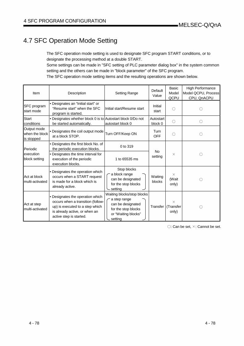
4 - 78 4 - 78
MELSEC-Q/QnA4 SFC PROGRAM CONFIGURATION
4.7 SFC Operation Mode Setting
The SFC operation mode setting is used to designate SFC program START conditions, or todesignate the processing method at a double START.Some settings can be made in "SFC setting of PLC parameter dialog box" in the system commonsetting and the others can be made in "block parameter" of the SFC program.The SFC operation mode setting items and the resulting operations are shown below.
Item Description Setting Range DefaultValue
BasicModelQCPU
High PerformanceModel QCPU, Process
CPU, QnACPU
SFC programstart mode
• Designates an “Initial start” or“Resume start” when the SFCprogram is started.
Initial start/Resume start Initialstart
Startconditions
• Designates whether block 0 is tobe started automatically.
Autostart block 0/Do notautostart block 0
Autostartblock 0
Output modewhen the blockis stopped
• Designates the coil output modeat a block STOP. Turn OFF/Keep ON Turn
OFF
• Designates the first block No. ofthe periodic execution blocks. 0 to 319
Periodicexecutionblock setting
• Designates the time interval forexecution of the periodicexecution blocks.
1 to 65535 ms
Nosetting
Act at blockmulti-activated
• Designates the operation whichoccurs when a START requestis made for a block which isalready active.
Stop blocks a block range can be designated for the stop blocks setting
Waitingblocks (Wait
only)
Act at stepmulti-activated
• Designates the operation whichoccurs when a transition (follow-up) is executed to a step whichis already active, or when anactive step is started.
Waiting blocks/stop blocks a step range can be designated for the stop blocks or “Waiting blocks” setting
Transfer (Transferonly)
: Can be set, : Cannot be set.

4 - 79 4 - 79
MELSEC-Q/QnA4 SFC PROGRAM CONFIGURATION
4.7.1 SFC program start mode
The SFC program start mode setting determines whether an SFC program START (SM321 OFF ON) is executed by an “Initial start,” or by a Resume start from the preceding execution status.
(1) Settings and corresponding operationsSet whether "initial start" or "resume start" will be selected for the SFC program.(a) Initial start
The program is started after the active status at a previous stop is cleared.The operation after a start is performed according to the setting of block 0 STARTcondition.
(b) Resume startThe program is started with the active status at a previous stop (ON to OFF of SM321 orRUN to STOP of CPU module) held.
The SFC program start mode changes depending on the combination of the setting of the"SFC program start mode" in the PLC parameter dialog box and the ON/OFF status of the"special relay for setting SFC program start status (SM322)" as indicated below.
Initial Start Resume StartSFC ProgramStart Mode
Operation
SM322: OFF(Initial status) 1
SM322: ON(When changed by
user)
SM322: OFF(Initial status) 1
SM322: ON(When changed by
user)SM321 is turned from OFF to ON Resume InitialPLC power is switched OFF, then ON Resume/Initial 3 InitialPLC power is switched OFF, then ONafter SM321 ON to OFF or RUN to STOP Resume *2 Resume 2
Reset operation to RUN Initial InitialReset operation to RUN after SM321 ONto OFF or RUN to STOP
Initial Initial
Resume 2 Resume 2
STOP to RUN ResumeSTOP to program write to RUN Initial Initial/Resume 4
Initial: Initial start, Resume: Resume start
1: SM322 is turned ON/OFF by the system according to the setting of the "SFC program start mode" inthe PLC parameter dialog box when the CPU module switches from STOP to RUN.• At initial start setting: OFF• At resume start setting: ON
2: Operation at resume startAt a resume start, the SFC program stop position is held but the status of each device used for theoperation output is not held.Therefore, make latch setting for the devices whose statuses must be held in making a resume start.• The held coil HOLD step SC becomes inactive, and is not kept held.
In the Basic model QCPU, the held coil HOLD step SC restarts in the held status. However, theoutput is not held. To hold the output, make latch setting for the devices desired to be held.
3: Depending on the timing, a resume start is disabled and an initial start may be made. When it isdesired to make a resume start securely, turn SM321 from ON to OFF or switch the CPU moduleform RUN to STOP, and then power the PLC OFF, then ON.The Basic model QCPU always makes an initial start.

4 - 80 4 - 80
MELSEC-Q/QnA4 SFC PROGRAM CONFIGURATION
4: A resume start may be made depending on the SFC program change.If a resume start is made as-is, a start is made from the old step number, leading to a malfunction ofthe mechanical system.When any SFC program change (SFC diagram correction such as step addition and deletion) hasbeen made, make an initial start once and then return it to a resume start.The Basic model QCPU always makes an initial start.
POINT(1) When the PLC is powered OFF or the CPU module is reset, the intelligent function
module/special function module is initialized.When making a resume start, create an initial program for the intelligent functionmodule/special function module in the block that is always active or in the sequenceprogram.
(2) When the PLC is powered OFF or the CPU module is reset, the devices not latched arecleared.Make latch setting to hold the SFC information devices.

4 - 81 4 - 81
MELSEC-Q/QnA4 SFC PROGRAM CONFIGURATION
4.7.2 Block 0 START condition
The block 0 START condition is designed to set whether block 0 will be automatically activated ornot at SFC program START (when SM321 turns from OFF to ON).
Use the block 0 START condition when it is desired to specify the START block at SFC programSTART according to the product type, etc."Auto START ON" is useful when block 0 is used as described below.• Used as a control block• Used as a preprocessing block• Used as an always watched block
(1) Settings and corresponding operationsSet block 0 to "Auto START ON" or "Auto START OFF".At SFC program START and END step execution, operations are performed as describedbelow.
OperationSetting
At SFC Program START At end step execution in block 0Autostart block 0
(default)• Block 0 is automatically activated, and is
executed from its initial step.• When the end step is reached, the initial step
is automatically activated again.
Do not autostart block 0
• Block 0 is activated by a START requestresulting from an SFC control “block START”instruction or a block START step, in the samemanner as other blocks.
• When the end step is reached, block 0 isdeactivated and waits for another STARTrequest to be issued again.

4 - 82 4 - 82
MELSEC-Q/QnA4 SFC PROGRAM CONFIGURATION
4.7.3 Output mode at block STOP
The "output mode at block STOP" is designed to set whether the coil outputs turned ON by theOUT instruction will be held at the time of a stop (coil output held) or all coil outputs will be forciblyturned OFF (coil output OFF) when the corresponding block is stopped temporarily.Stop the corresponding block temporarily using the "stop RESTART bit" of the SFC informationdevices or the "block STOP instruction (PAUSE BLm)" of the SFC control instructions.
(1) Settings and corresponding operationsSet the output mode at block STOP in the "output mode at block STOP in PLC parameterdialog box" or the "special register for setting operation output at block STOP (SM325)".The operation of the SFC program changes depending on the combination of the "outputmode at block STOP in PLC parameter dialog box" setting and the SM325 setting.
OperationHeld step *
Setting ofOutput Mode atBlock Stop in
PLC Parameter
OperationOutput at
Block Stop(SM325)
Status ofSTOP-timeMode Bit
Active step other than held step(including HOLD step (SC, SE, ST) whose
transition condition is not satisfied) Coil HOLD step (SC)Operation HOLD
step (withouttransition check) (SE)
Operation HOLDstep (with transition
check) (ST)OFF or nosetting(immediatestop)
• Immediately after a STOP request is made,the coil output of the operation output is turnedOFF and the block is stopped.
• The status remains active.• Turns OFF(coil outputOFF)
• Remains ON(coil outputheld)
• OFF(coiloutputOFF) ON
(STOP aftertransition)
• Normal operation is performed until thetransition condition is satisfied.
• When the transition condition is satisfied, theend processing of the corresponding step isperformed.At the same time, the transition destinationstep becomes active and the block stopsimmediately.
• Immediately after aSTOP request ismade, the coiloutput of theoperation output isturned OFF and theblock is stopped.
• The statusbecomes inactive.
• Immediately after a STOP request ismade, the coil output of the operationoutput is turned OFF and the block isstopped.
• The status remains active.
OFF or nosetting(immediatestop)
• Immediately after a STOP request is made,the block is stopped with the coil output of theoperation output being held.
• The status remains active.
• Remains ON(coil outputheld)
• ON(coiloutputheld) ON
(STOP aftertransition)
• Normal operation is performed until thetransition condition is satisfied.
• When the transition condition is satisfied, theend processing of the corresponding step isperformed.At the same time, the transition destinationstep becomes active and the block stopsimmediately.
• Immediately after a STOP request is made, the block is stoppedwith the coil output of the operation output being held.
• The status remains active.
*: The held step indicates the step whose attribute has been set to the HOLD step (SC, SE, ST) and which is being held with thetransition condition satisfied.
(a) Output mode at block STOP in PLC parameter dialog boxSet the initial status of the output mode at block STOP when the PLC is powered ON or theCPU module is reset.
(b) SM3251) SM325 is turned ON/OFF by the system according to the parameter setting when the
CPU module switches from STOP to RUN.
Parameter Setting SM325
Turns OFF (coil output OFF) OFFRemain ON (coil output held) ON
2) By turning ON/OFF SM325 during SFC program operation, the setting of the "outputmode at block STOP" can be changed.(During SFC program operation, the "output mode at block STOP" in the PLC parameterdialog box is ignored.)

4 - 83 4 - 83
MELSEC-Q/QnA4 SFC PROGRAM CONFIGURATION
4.7.4 Periodic execution block setting
The periodic execution block setting designates the execution of a given block at specified timeintervals rather than at each scan.
(1) Setting itemsDesignate the first block number and the time of execution for the periodic execution blocks.When these settings are designated, the “first block” and all subsequent blocks will becomeperiodic execution blocks.The execution time interval setting can be designated in 1 ms units within a 1 to 65535 msrange.
(2) Periodic execution block operation methodPeriodic execution block operation occurs as shown below.
(3)
1 scan
(2)(1) (4)(2)(1) (3) (3)(2)(1) (4)(2)(1) (3)
Execution interval Execution interval
1 scan 1 scan 1 scan
(1) Sequence programs executed at each scan(2) Blocks executed at each scan(3) END processing(4) Periodic execution blocks
1) Until the specified time interval elapses, only the sequence programs and blocks designatedfor execution at each scan will be executed.
2) When the specified time interval elapses, the periodic execution blocks will be executedfollowing execution of blocks designated for execution at each scan. If the specified timeinterval is shorter than the scan time, the periodic execution blocks will be executed at eachscan in the same manner as the other blocks.
3) The specified time interval countdown is executed in a continuous manner.
POINT(1) When the parameter where the "high-speed interrupt fixed-cycle interval" has been set is
written to the High Performance model QCPU whose first five digits of serial No. are"04012" or later, the fixed-cycle execution block setting cannot be used.If the fixed-cycle execution block setting is made, no processing is performed and the blockremains unchanged from the every scan execution block.
(2) To execute the periodic execution block, the block to be executed periodically must beactivated.
(3) The fixed-cycle execution block setting cannot be used in the Basic model QCPU.

4 - 84 4 - 84
MELSEC-Q/QnA4 SFC PROGRAM CONFIGURATION
4.7.5 Operation mode at double block START
This mode setting designates the operation mode which is to be effective when a block STARTrequest occurs (by block START step ( m, m)) for a block which is already started.
(1) Settings and corresponding operationsSet the operation mode at block double START to either STOP or WAIT in the "blockparameter" of the SFC setting dialog box in the Tools menu.The operations resulting from these settings are shown below.
Setting Operation Remarks
STOP• A CPU module operation error (BLOCK EXE.ERROR)
occurs, and CPU module operation is stopped.• All “Y” outputs switch OFF.
• A block range can bedesignated for the STOPsetting.
WAIT (default)
• CPU module operation continues, and a WAIT status isestablished when the transition condition is satisfied. TheWAIT status continues until the START destination block isdeactivated.
• A step transition occurs when the START destination blockis deactivated, and that block is then reactivated.
• If a transition WAIT occurs, the previous step isdeactivated, the output is switched OFF, and the operationoutput will not be executed.
ConditionTran
nTransition to stepin active block
HOLD step(with transition check)
POINT(1) When a START request is issued to the block that is already active by execution of the
following, the START request is ignored and the processing of the SFC program iscontinued as is.• Block START instruction (SET BLm) of SFC control instructions• ON of Block START/END bit of SFC information devices
(2) In the Basic model QCPU, the operation mode at block double START cannot be set.The operation mode at block double START in the Basic model QCPU is the default"WAIT" mode.

4 - 85 4 - 85
MELSEC-Q/QnA4 SFC PROGRAM CONFIGURATION
4.7.6 Operation mode at transition to active step (double step START)
This mode setting designates the operation mode which is to be effective when a follow-upfunction such as an operation HOLD step (with transition check) is used to execute a transition toa step which is already active.
(1) Settings and corresponding operationsFor a transition to an active step, set any of STOP, WAIT and TRANSFER in the "blockparameter" of the FC setting dialog box in the Tools menu.The operations resulting from these settings are shown below.
Setting Operation Remarks
STOP• A CPU module operation error (BLOCK EXE.ERROR)
occurs, and CPU module operation is stopped.• All “Y” outputs switch OFF.
• A step range can bedesignated for the STOPsetting.
WAIT
• CPU module operation continues, and a WAIT status isestablished when the transition condition is satisfied. TheWAIT status continues until the START destination step isdeactivated.
• If a transition WAIT occurs, the previous step isdeactivated, the output is switched OFF, and the operationoutput will not be executed.
• A step range can bedesignated for the WAITsetting.
TRANSFER (default)
• CPU module operation continues, the transition occurs,and the previous step is deactivated and absorbed by thetransition destination step.
Active stepCondition satisfied
Active step
Condition satisfied
Inactive
Active
(2) Transition to HOLD step by double STARTThe following table shows the transition procedure for transitions to coil HOLD steps, operationHOLD steps (with transition check), and operation HOLD steps (without transition check)which occur when the double START condition is satisfied. These transitions occur withoutregard to the settings described at item (1) above.
Setting Operation Remarks
STOP,WAIT,
TRANSFER
• The TRANSFER setting applies to all operations, regardless of thesetting.
• At coil HOLD steps......... The operation output is restarted, and a transition condition
check begins.The PLS instruction for which the input conditions havealready been established is non-executable until the inputconditions are turned on again.
• At operation HOLD steps (without transition check)........ A transition condition check begins.
• At operation HOLD steps (with transition check)........ Operation continues as is.
Active stepTransition condition satisfied
Inactive
Active
(No transition condition check)
Coil HOLD step oroperation output step(without transition check) Transition condition
is checked
• Following the doubleSTART, execution of allsubsequent steps wheretransition conditions aresatisfied will occur accordingto the step attributes.
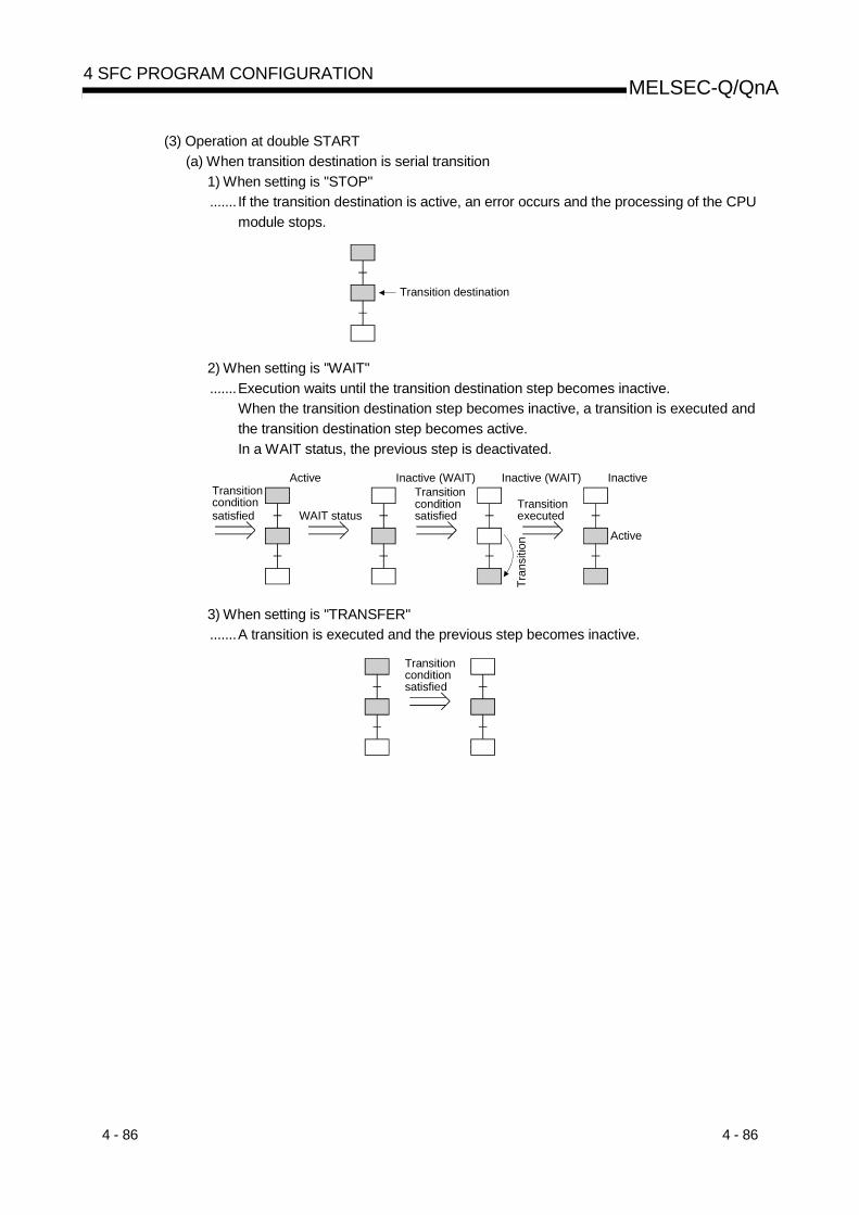
4 - 86 4 - 86
MELSEC-Q/QnA4 SFC PROGRAM CONFIGURATION
(3) Operation at double START(a) When transition destination is serial transition
1) When setting is "STOP"....... If the transition destination is active, an error occurs and the processing of the CPU
module stops.
Transition destination
2) When setting is "WAIT".......Execution waits until the transition destination step becomes inactive.
When the transition destination step becomes inactive, a transition is executed andthe transition destination step becomes active.In a WAIT status, the previous step is deactivated.
WAIT status
ActiveTransition condition satisfied
Transitionconditionsatisfied
Inactive (WAIT)
Transitionexecuted
InactiveInactive (WAIT)
ActiveTr
ansi
tion
3) When setting is "TRANSFER".......A transition is executed and the previous step becomes inactive.
Transitionconditionsatisfied

4 - 87 4 - 87
MELSEC-Q/QnA4 SFC PROGRAM CONFIGURATION
(b) When transition destination is parallel branch1) When setting is "STOP"
.......If any one of the transition destinations of the parallel branch is active, an erroroccurs and the processing of the CPU module stops.
Transition destination
2) When setting is "WAIT".......Execution waits until all the transition destination steps of the parallel branch
become inactive.When the transition destination steps all become inactive, a transition is executedand all the first steps of the parallel branch become active.
In a WAIT status, the previous step is deactivated.Transitionconditionssatisfied
Transitionexecuted
Tran
sitio
n
InactiveTransition conditionssatisfied
Inactive(WAIT)
Inactive
All active
WAIT status
ActiveTransition conditionsatisfied
3) When setting is "TRANSFER".......When any one of the transition destination steps of the parallel branch is active, a
transition is executed and the previous step becomes inactive.Transition conditionsatisfied
REMARK
When the transition destination steps are all inactive, normal transition processing is performedand all the transition destination steps become active.
POINTS(1) The operation mode for transition to active step (at step double START) applies to a
transition to be executed when a transition condition is satisfied or to a forced transition setusing the transition control instruction (SET TRn) of the SFC control instructions.When the step control instruction (SET Sn) of the SFC control instructions is used to issuea START request to the step that is already active, the request is ignored and theprocessing continues.
(2) In the Basic model QCPU, the transition to active step (at step double START) cannot beset.The transition to active step (at step double START) in the Basic model QCPU is executedin the "TRANSFER" mode.

4 - 88 4 - 88
MELSEC-Q/QnA4 SFC PROGRAM CONFIGURATION
MEMO

5 - 1 5 - 1
MELSEC-Q/QnA5 SFC PROGRAM PROCESSING SEQUENCE
5. SFC PROGRAM PROCESSING SEQUENCE
5.1 Whole Program Processing of Basic Model QCPUThis section explains the program processing of the Basic model QCPU.Since this manual describes only the outline, refer to the user's manual of the used CPU modulefor details.
5.1.1 Whole program processing sequenceThe Basic model QCPU can create and execute two programs, "sequence program" and "SFCprogram", in the program memory.(Two sequence programs or two SFC programs cannot be created. A SFC program for programexecution management cannot be created either.)
SFC program(MAIN-SFC)
Sequence program(MAIN)
CPU module RUN
Executed every scan.(Execution order cannot be changed.)
(a) The execution types of the sequence program and SFC program are fixed to the "scanexecution type".(The execution types of the sequence program and SFC program are fixed.)
(b) The Basic model QCPU executes the SFC program after execution of the sequenceprogram.(The execution order of the sequence program and SFC program is fixed.)
(c) The file name of the sequence program is fixed to "MAIN".Also, the file name of the SFC program is fixed to "MAIN-SFC".
POINTWhen both the "sequence program" and "SFC program" exist in the programmemory, both programs are executed.Delete the programs, which will not be executed, from the program memory.When ROM operation is performed, delete the programs, which will not beexecuted, from the standard ROM.
5

5 - 2 5 - 2
MELSEC-Q/QnA5 SFC PROGRAM PROCESSING SEQUENCE
5.2 Whole Program Processing of High Performance ModelQCPU/Process CPU/QnACPU
This section explains the whole program processing of the High Performance model QCPU,Process CPU and QnACPU.Since this manual describes only the outline, refer to the user's manual of the used CPU modulefor details.
5.2.1 Whole program processing sequence
The High Performance model QCPU, Process CPU and QnACPU can store multiple programs inthe program memory as files and execute multiple files concurrently or only the specified file.The whole operation image is as shown below.
Initial execution type program
Low-speed execution type program
Scan execution type program
Standby type program
Started only when necessary.
CPU module RUN
Execution time monitoring
1)
2)
3)
4)
Fixed-cycle execution type program
5)
Can be executed by High Performance model QCPU or Process CPU.
5

5 - 3 5 - 3
MELSEC-Q/QnA5 SFC PROGRAM PROCESSING SEQUENCE
Execution Type Description SFC Compatibility
(1)Initial execution typeprogram(initial execution)
• Executed only in one scan when the PLC is powered ONor the CPU module is switched from STOP to RUN.
• After that switches to a standby program.
(2)Scan execution typeprogram(scan execution)
• Program executed every scan.
Max. 124 programs(changes depending on theCPU module type)• SFC program:
Max. 2 programs• Normal SFC program:
1 program• SFC program for program
execution management:1 program
(3)Low speed execution typeprogram(low speed execution)
• Program executed in the extra time of the constant scantime, or program executed only during preset time.
(4) Stand-by type program(waiting)
• Programs such as a subroutine program and interruptprogram.
• Started by the program START instruction for execution.
Max. 124 programs(changes depending on theCPU module type)
(5)Fixed-cycle execution typeprogram(Fixed cycle)
• Program executed in a fixed cycle.
: Cannot be set.
REMARKS
(1) When the SFC program set as a standby type program is to be started, the SFC program inexecution must be switched to a standby type program before it is started.Refer to Section 5.2.2 for the method of switching between the scan execution type programand standby type program.
(2) Specify the execution type of each program file in "Program setting" of the PLC parameterdialog box.

5 - 4 5 - 4
MELSEC-Q/QnA5 SFC PROGRAM PROCESSING SEQUENCE
5.2.2 Execution type designation by instructions
The "execution designation by instruction" function enables the execution type set in the programsetting of the PLC parameter dialog box to be changed by the instruction.Execution designation by instruction will be explained.
(1) Instructions and corresponding operations
Instruction Operation SFCCompatibility
PSTOP • Switches the program of the specified file name to a standby status, beginning in thenext scan.
POFF• Executes the end processing of all blocks in the next scan in the SFC program of the
specified file name, and switches the program to a standby status in the secondscan after execution of the instruction.
PSCAN
• Switches the program of the specified file name to a scan execution type, beginningin the next scan.
• The execution order of multiple programs changes depending on the programsetting order in the PLC parameter dialog box.
PLOW
• Switches the program of the specified file name to a low-speed execution type,beginning in the next scan.
• The execution order of multiple programs changes depending on the programsetting order in the PLC parameter dialog box.
: Compatible, : Incompatible
REMARK
• The following conditions will result in an operation error:• When the specified program does not exist. (error No. 2410).• When the PSTOP or PLOW instruction is executed (error No. 2412)• When an SFC program is designated by the PSCAN instruction while scanning is in
progress at another SFC program (error No. 2412).• When the specified SFC program is in scan execution or not can be confirmed with the
PCHK instruction.For details of the PCHK instruction, refer to the QCPU (Q mode)/QnACPU ProgrammingManual (Common Instructions).
(2) Instruction format
Character string or word device where character string is storedPOFF, PSCAN
Program nameInstruction

5 - 5 5 - 5
MELSEC-Q/QnA5 SFC PROGRAM PROCESSING SEQUENCE
(3) Processing time required to switch SFC program from WAIT status to scan statusThe processing time required to switch an SFC program from a WAIT status to a scan status isshown below.Although the scanning time is extended by the amount of the processing time, this will notresult in a watch dog timer error detection.No system processing time is required when switching from a scan status to a WAIT status.Switching time =(number of created programs × Km) + (number of created steps × Kn) + (SFCprogram capacity × Kp)
High Performance Model QCPU Process CPU
Q02CPU QnHCPU QnPHCPUQ2ACPU (S1)
Q2ASCPU (S1) Q3ACPUQ4ACPU
Q4ARCPUQ2ASHCPU (S1)
Km 451.9µs 194.7µs 194.7µs 1145.3µs 859.0µs 429.5µs
Kn 19.1µs 8.2µs 8.2µs 48.3µs 36.2µs 18.1µs
Kp 6.2µs 2.7µs 2.7µs 15.7µs 11.8µs 5.9µs

5 - 6 5 - 6
MELSEC-Q/QnA5 SFC PROGRAM PROCESSING SEQUENCE
5.2.3 SFC program for program execution management
This SFC program can be used to manage the program execution sequence when multipleprogram file switching is required.In addition to a normal SFC program, only one block can be created and executed for a single fileof an SFC program for program execution management.
(1) How to create SFC program for program execution management
(a) Number of files and blocksIn addition to a normal SFC program, only one file of an SFC program for programexecution management can be created as a scan execution type program.Only one block of the SFC program for program execution management can be created.
(b) Usable instructionsThe SFC diagram symbols (except the block START steps ( m, m)) and steps that canbe used in an SFC program and the sequence instructions that can be used in transitionconditions can all be used.
POINTIf block start steps ( m, m) are described, a “BLOCK EXE. ERROR” error (error No. 4621)will occur during SFC program execution and the CPU module will stop the execution.
(2) Execution procedureThe program is started automatically when registered as a scan execution type program.At end step processing, the initial step is reactivated and processing is repeated.
REMARKS
(1) Use the peripheral device to select between the SFC program for program executionmanagement and the normal SFC program.For details regarding the setting procedure, refer to the GX Developer Operating Manual(SFC).
(2) Periodic execution block settings (see Section 4.7.4) cannot be defined the SFC programsfor program execution control.If a SFC program for program execution control is set in a periodic execution block, theexecution of the SFC program will not be performed.
(3) The Basic mode QCPU cannot use the SFC program for program execution management.

5 - 7 5 - 7
MELSEC-Q/QnA5 SFC PROGRAM PROCESSING SEQUENCE
(3) Example of program execution management SFC programs
SFC1, SFC2 and SFC3 are assumed to be SFC program files and SQ is assumed to be aprogram file for a program other than an SFC program.
TRANCondition 3
Condition 4
Condition 5
TRAN
Condition 4
TRANCondition 5
Condition 6
TRAN
S0
t0
S1
t1
t2
S2
t3
(INV: inverse of previous operation result)
Condition 2
Condition 1PSCAN “SFC1”
PSCAN “SQ”
POFF “SFC1”
PCHK “SFC1”
PSCAN “SFC2”
POFF “SFC2”
PCHK “SFC2”
PCHK “SFC2”
PSCAN “SFC3”
POFF “SFC3”
PCHK “SFC3”
The SFC program for preprocessing control such as zero return (SFC1) and the sequence program for constant monitoring (SQ) are changed to the scan execution type.
An SFC program changes to the standby type by the zero return END signal.
When an SFC program (SFC1) changes to the standby type, a selection transition occurs if condition 3 (product type, etc.) is ON.
•
The SFC program for automatic operation (SFC2) is changed to the scan execution type.
The SFC program (SFC2) is changed to the standby type when the automatic operation END condition, e.g. a cycle stop or emergency stop, is satisfied.
When condition 5 is satisfied (forced END by emergency STOP, etc.) a selec-tion transition to S2 occurs after the tran-sition condition is satisfied.
When the transition condition is satisfied as condition 4 is satisfied (normal END by a cycle STOP, etc.), execution proceeds to the end step and S0 is reactivated.
When the transition condition is satisfied at error processing completion, execution proceeds to the end step and S0 is reactivated.
When condition 6 is satisfied (error processing completion), the SFC program (SFC3) is put in a wait status.
The error processing SFC program (SFC3) is changed to the scan execution type.
•
•
•
•
•
•
•
•
•
S0
S1
t0
t1
S2
t2
t3
The processing sequence when transition condition t4 is satisfied is the same as thatshown above except for a different “product type”.
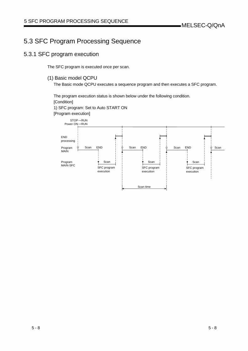
5 - 8 5 - 8
MELSEC-Q/QnA5 SFC PROGRAM PROCESSING SEQUENCE
5.3 SFC Program Processing Sequence
5.3.1 SFC program execution
The SFC program is executed once per scan.
(1) Basic model QCPUThe Basic mode QCPU executes a sequence program and then executes a SFC program.
The program execution status is shown below under the following condition.[Condition]1) SFC program: Set to Auto START ON[Program execution]
STOP RUNPower ON RUN
END processing
ScanProgramMAIN
ProgramMAIN-SFC
SFC program execution
Scan
END0 Scan END0
SFC program execution
Scan
Scan END0
SFC program execution
Scan
Scan0
Scan time

5 - 9 5 - 9
MELSEC-Q/QnA5 SFC PROGRAM PROCESSING SEQUENCE
(2) High Performance model QCPU, Process CPU, QnACPUThe High Performance model QCPU, Process CPU and QnACPU can execute multipleprograms stored in the program memory.(Scan execution is enabled for two SFC programs (one SFC program for program executionmanagement and one normal SFC program).Multiple programs are executed in the order of the program setting in the PLC parameterdialog box.
The execution status of multiple programs is shown below under the following conditions.[Condition]1) Program setting in PLC parameter dialog box
1: ABC (sequence) <scan>2: DEF (SFC) <scan>3: XYZ (sequence) <low speed>
2) Low-speed program time setting in parameter: 5ms3) SFC program: Set to Auto START ON
[Program execution]
ProgramABC
DEF
XYZ
END0 END0 END0 0
STOP RUNPower ON RUN
END processing
Program
Scan
Scan
SFC program execution Low
speedLow speed
Scan
Scan
SFC program execution
Scan
Scan
SFC program execution Low
speed
Scan
Scan time
Program
REMARKS
Refer to Section 6.1 for the SFC program start/stop method.

5 - 10 5 - 10
MELSEC-Q/QnA5 SFC PROGRAM PROCESSING SEQUENCE
5.3.2 Block execution sequence
(1) In the SFC program, the step in the active block is executed every scan.
(2) When there are multiple blocks, the blocks are processed in order of lower to higher blocknumbers.(a) In the active block, the active step in that block is executed.
(b) The inactive block is checked for a START request, and if there is a START request, theblock is activated and the step in that block is executed.
Block0 Block1 Block2
S0
S1BLT1
S2
1) 3)
4)
5) 6)
2)
BLT2
S0
S1
S2
: Active step, : Inactive step
t0
t1
t2
S0
S1
S2
t0
t1
t2
t0
t1
t2
The SFC program is executed in order of 1) to 6).1): Whether block 0 is active or inactive is checked.2): Since block 0 is active, the active step (S2) is executed.3): Whether block 1 is active or inactive is checked.4): Since block 1 is active, the active step (S0) is executed.5): Whether block 2 is active or inactive is checked.6): Since block 2 is inactive, whether the next block is active or inactive is checked.
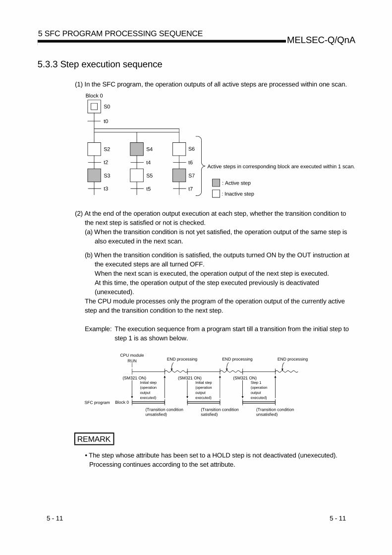
5 - 11 5 - 11
MELSEC-Q/QnA5 SFC PROGRAM PROCESSING SEQUENCE
5.3.3 Step execution sequence
(1) In the SFC program, the operation outputs of all active steps are processed within one scan.Block 0
S0
S2
S3
S4
S5
S6
S7 : Active step
: Inactive step
Active steps in corresponding block are executed within 1 scan.
t0
t2
t3
t4
t5
t6
t7
(2) At the end of the operation output execution at each step, whether the transition condition tothe next step is satisfied or not is checked.(a) When the transition condition is not yet satisfied, the operation output of the same step is
also executed in the next scan.
(b) When the transition condition is satisfied, the outputs turned ON by the OUT instruction atthe executed steps are all turned OFF.When the next scan is executed, the operation output of the next step is executed.At this time, the operation output of the step executed previously is deactivated(unexecuted).
The CPU module processes only the program of the operation output of the currently activestep and the transition condition to the next step.
Example: The execution sequence from a program start till a transition from the initial step tostep 1 is as shown below.
SFC program
CPU moduleRUN
(SM321 ON)
END processing
(Transition conditionunsatisfied)
(SM321 ON)
END processing
(Transition conditionsatisfied)
(SM321 ON)
END processing
Initial step(operationoutputexecuted)
Initial step(operationoutputexecuted)
Step 1(operationoutputexecuted)
Block 0
(Transition conditionunsatisfied)
REMARK
• The step whose attribute has been set to a HOLD step is not deactivated (unexecuted).Processing continues according to the set attribute.

5 - 12 5 - 12
MELSEC-Q/QnA5 SFC PROGRAM PROCESSING SEQUENCE
5.3.4 Continuous transition ON/OFF operation
There are two types of SFC program transition processing: "with continuous transition" and"without continuous transition".Set "with continuous transition" or "without continuous transition" using the continuous transitionbit of the SFC information devices.When the device set to the continuous transition bit is turned ON/OFF by the user, operation isperformed as described below.
ContinuousTransition Bit
SM323 Operation
OFFWithout continuoustransition
When the transition condition is satisfied, the operationoutput of the transition destination step is executed in thenext scan.
No setting
ONWith continuoustransition
When the transition condition is satisfied, the operationoutput of the transition destination step is executed withinthe same scan.When the transition conditions of the steps are satisfiedcontinuously, the operation outputs are executed within thesame scan until the transition condition is not satisfied orthe end step is reached.
OFF ON/OFFWithout continuoustransition
When the transition condition is satisfied, the operationoutput of the transition destination step is executed in thenext scan.
ON ON/OFFWith continuoustransition
When the transition condition is satisfied, the operationoutput of the transition destination step is executed withinthe same scan.When the transition conditions of the steps are satisfiedcontinuously, the operation outputs are executed within thesame scan until the transition condition is not satisfied orthe end step is reached.
POINTThe tact time can be shortened by setting "with continuous transition".This resolves the problem of waiting time from when the transition condition issatisfied until the operation output of the transition destination step is executed.However, when "with continuous transition" is set, the operations of the otherblocks and sequence program may become slower.Refer to Section 4.5.5 for details of continuous transition.
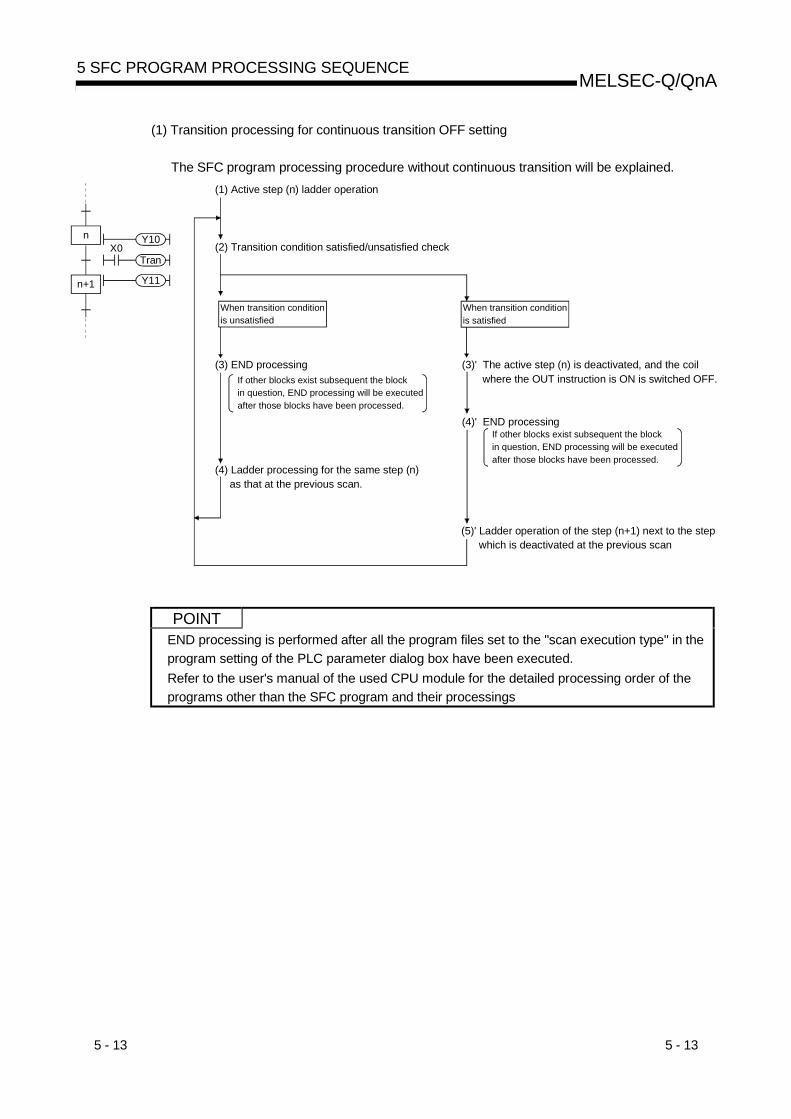
5 - 13 5 - 13
MELSEC-Q/QnA5 SFC PROGRAM PROCESSING SEQUENCE
(1) Transition processing for continuous transition OFF setting
The SFC program processing procedure without continuous transition will be explained.
TranX0
Y10
Y11
n
n+1
(1) Active step (n) ladder operation
(2) Transition condition satisfied/unsatisfied check
When transition conditionis unsatisfied
(3) END processing
(4) Ladder processing for the same step (n) as that at the previous scan.
When transition conditionis satisfied
(3)' The active step (n) is deactivated, and the coil where the OUT instruction is ON is switched OFF.If other blocks exist subsequent the block
in question, END processing will be executed after those blocks have been processed.
(4)' END processingIf other blocks exist subsequent the block in question, END processing will be executed after those blocks have been processed.
(5)' Ladder operation of the step (n+1) next to the step which is deactivated at the previous scan
POINTEND processing is performed after all the program files set to the "scan execution type" in theprogram setting of the PLC parameter dialog box have been executed.Refer to the user's manual of the used CPU module for the detailed processing order of theprograms other than the SFC program and their processings

5 - 14 5 - 14
MELSEC-Q/QnA5 SFC PROGRAM PROCESSING SEQUENCE
(2) Transition processing for “continuous transition ON” setting
The SFC program processing procedure with continuous transition will be explained.
TranX0
Y10
Y11
n
n+1
(1) Active step (n) ladder operation
(2) Transition condition satisfied/unsatisfied check
When transition conditionis unsatisfied
(3) END processing
(4) Ladder processing for the same step (n) as that at the previous scan.
When transition conditionis satisfied
(3)' The active step (n) is deactivated, and the coil where the OUT instruction is ON is switched OFF.
(4)' Step “n+1” is activated, and its ladder operation occurs.
(5)' Transition condition satisfied/unsatisfied check
(6)' Subsequent processing is executed in a continuous manner up to a step with an unsatisfied transition condition.
(7)' END processing
If other blocks exist subsequent the block in question, END processing will be executed after those blocks have been processed.
If other blocks exist subsequent the block in question, END processing will be executed after those blocks have been processed.
(8)' Ladder operation is executed for the step activated by the unsatisfied transition condition at the previous scan.
POINTEND processing is performed after all the program files set to the "scan execution type" in theprogram setting of the PLC parameter dialog box have been executed.Refer to the user's manual of the used CPU module for the detailed processing order of theprograms other than the SFC program and their processings.

6 - 1 6 - 1
MELSEC-Q/QnA6 SFC PROGRAM EXECUTION
6. SFC PROGRAM EXECUTION
6.1 SFC Program START And STOP
There are the following three types of SFC program start and stop methods.• Auto START using PLC parameter• Start and stop using the special relay for SFC program start/stop (SM321)• Start and stop using the PSCAN/POFF instruction (except the Basic model QCPU)• Start and stop using GX Developer
(1) Auto START using PLC parameterSet the start condition in the "SFC setting" of the PLC parameter dialog box to "Block 0 AutoSTART".The SFC program is started when the CPU module switches from STOP to RUN.(When the SFC program starts, block 0 also starts.)
(2) Start and stop using the special relay for SFC program start/stop (SM321)SM321 turns ON when an Auto START is made using the PLC parameter.(a) Turn OFF SM321 to stop the SFC program execution.
(b) Turn ON SM321 to start the SFC program.
(3) Start and stop using the PSCAN/POFF instruction (except the Basic modelQCPU)SM321 turns ON when an Auto START is made using the PLC parameter.(a) When the POFF instruction is executed, the SFC program in execution turns off the output
and then stops.The execution type changes to the "standby type".
(b) When the PSCAN instruction is executed, the standby type SFC program can be started.However, when the SFC program has not been set to the "scan execution type" (SM321 isOFF) in the program setting of the PLC parameter dialog box, the SFC program is startedby turning ON Sm321.The execution type changes to the "scan execution type".
6

6 - 2 6 - 2
MELSEC-Q/QnA6 SFC PROGRAM EXECUTION
6.1.1 SFC program resumptive START procedure
The SFC program START format can be designated as “initial START” or “resumptive START”.The “resumptive START” setting procedure as well as some precautions regarding the“resumptive START” format are described below.
(1) Resumptive START setting procedureMake the resume START setting of the SFC program in the "SFC program start mode" of theSFC setting in the PLC parameter dialog box.
(2) Block operation status resulting from “SFC program START mode” settingAt an SFC program start, whether an initial start or resume start will be made is determined bythe combination of the setting of the "SFC program start mode" in the PLC parameter dialogbox and the ON/OFF status of the "special relay for setting SFC program start status(SM322)".
SFC Program Start ModeInitial Start Resume Start
Operation
SM322: OFF(Initial status) 1
SM322: ON(When changed by
user)
SM322: ON(Initial status) 1
SM322: OFF(When changed by
user)SM321 is turned from OFF ON Resume Initial
PLC power is switched OFF,then ON Resume/Initial 3 Initial
PLC power is switched OFF,then ON after SM321 ON OFF or RUN STOP
Resume 2 Resume 2
Reset operation to RUN Initial InitialReset operation to RUN afterSM321 ON OFF or RUN STOP
Initial Initial
Resume 2 Resume 2
STOP RUN ResumeSTOP program write RUN Initial Initial/Resume 4
Initial: Initial start, Resume: Resume start1: SM322 is turned ON/OFF by the system according to the setting of the "SFC program start
mode" in the PLC parameter dialog box when the CPU module switches from STOP RUN.• At initial start setting: OFF• At resume start setting: ON
2: Operation at resume startAt a resume start, the SFC program stop position is held but the status of each device usedfor the operation output is not held.• Therefore, make latch setting for the devices whose statuses must be held in making a
resume start.The held coil HOLD step SC becomes inactive, and is not kept held.In the Basic model QCPU, the held coil HOLD step SC restarts in the held status.However, the output is not held. To hold the output, make latch setting for the devicesdesired to be held.
3: Depending on the timing, a resume start is disabled and an initial start may be made. When itis desired to make a resume start securely, turn SM321 from ON OFF or switch the CPUmodule from RUN STOP, and then power the PLC OFF, then ON.Note that the Basic model QCPU always makes an initial start.
6

6 - 3 6 - 3
MELSEC-Q/QnA6 SFC PROGRAM EXECUTION
4: A resume start may be made depending on the SFC program change.If a resume start is made as-is, a start is made from the old step number, leading to amalfunction of the mechanical system.When any SFC program change (SFC diagram correction such as step addition and deletion)has been made, make an initial start once and then return it to a resume start.Note that the Basic model QCPU always makes an initial start.
POINTS(1) When the PLC is powered OFF or the CPU module is reset, the intelligent function
module/special function module is initialized.When making a resume start, create an initial program for the intelligent functionmodule/special function module in the block that is always active or in the sequenceprogram.
(2) When the PLC is powered OFF or the CPU module is reset, the devices not latched arecleared.Make latch setting to hold the SFC information devices.

6 - 4 6 - 4
MELSEC-Q/QnA6 SFC PROGRAM EXECUTION
6.2 Block START and END
6.2.1 Block START methods
The block START methods during SFC program execution are described below.
As shown below, there are several block START methods. Choose the method which is mostsuitable for the purpose at hand.
START Method Operation Description Remarks Block 0 Other thanBlock 0
Auto START using PLCparameter
• By setting the "start condition" to "block0 Auto START" in the SFC setting of thePLC parameter dialog box, block 0 isautomatically started at an SFC programstart, and processing is executed fromthe initial step.
• Convenient when block 0 isused as a control block, apreprocessing block, or aconstant monitoring block, forexample.
Block START by SFCdiagram symbol
• Another block is started by the blockSTART steps ( m, m ) at each ofthe SFC program blocks.
Block m is started.
TRANm
m
• Convenient when thesequence control is clear asin automatic operation.
• There are 2 types of blockSTART:The START source stepremains active until theSTART destination block isended.The START source transitionoccurs without waiting for theSTART destination block tobe ended (SFC diagramsymbol: m).
Block START by SFCcontrol instruction
• Using an SFC control instruction, aspecified block is forcibly started from anSFC program step (operation output), orfrom another sequence program.(1) When specified block is executed
from its initial step:Condition
* “m” is the block No.
SET BLm
(2) When specified block is executedfrom a specified step:
ConditionSET BLm\Sn
* “m” is the block No., “n” is the step No.
• Convenient when starting anerror reset processing blockat error detection, etc., andfor executing interruptprocessing, for example.
Block START by SFCinformation device
• The corresponding block is activated byforcibly turning ON the "blockSTART/END bit", which was set to eachblock as the SFC information device, inthe program or peripheraldevice.information register.
• Convenient for debuggingand test operations in 1-blockunits because the block canbe started from a peripheraldevice without requiring aprogram.
: Usable, : Unusable

6 - 5 6 - 5
MELSEC-Q/QnA6 SFC PROGRAM EXECUTION
6.2.2 Block END methods
The methods for ending block operations are described below.
As shown below, there are several block END methods. Choose the method which is mostsuitable for the purpose at hand.
END Method Operation Description Remarks
Block END by SFCdiagram symbol
• Block processing is ended and the block isdeactivated when the block's END step isexecuted.
END step
• Convenient for cycle stops at automaticoperations, etc.
• Multiple END steps are possible within a singleblock.
Block END by SFCcontrol instruction
• Using an SFC control instruction, a specifiedblock is forcibly ended and deactivated froman SFC program step (operation output), orfrom another sequence program.
Condition
* “m” is the block No.
RST BLm
Block processing is also ended when theRST BLm/Sn instruction is usedtodeactivate all steps at a specified block.
• Convenient for executing a forced STOP (atemergency stops, etc.) without regard to theoperation status.
Block END by SFCinformation device
• The processing of the corresponding block isended to deactivate it by forcibly turning OFFthe "block START/END bit", which was set toeach block as the SFC information device, inthe program or peripheral device.
• Convenient for debugging and test operationsbecause block processing can be ended froma peripheral device without requiring aprogram.
POINTS(1) A forced end to block processing is possible using a method which is different from that
used to start the block.Example: 1) A block started by an SFC diagram symbol ( m, m ) can be ended by an
SFC control instruction (RST BLm). 2) A block started by an SFC control instruction (SET BLm) can be ended by
forcibly turning OFF the block START/END bit of the SFC informationdevices.
(2) After block END processing is completed, the block can be restarted as shown below.
Block
When the Start conditions isdesignated as “Autostart block 0”
• After block processing is ended,processing is started automaticallyfrom the initial step.
Block 0When the Start conditions isdesignated as “Do not autostartblock 0”
Other than block 0
• After block processing is ended, theblock remains inactive until aSTART request occurs by one ofthe methods described in Section6.2.1.

6 - 6 6 - 6
MELSEC-Q/QnA6 SFC PROGRAM EXECUTION
6.3 Block Temporary Stop and Restart Methods
6.3.1 Block STOP methods
The temporary block STOP methods which can be used during SFC program execution aredescribed below.
(1) Block STOP methodsThe methods for temporarily stopping a block during SFC program operation are shown below.
STOP Method Operation Description Remarks
Block STOP by SFCcontrol instruction
• Using an SFC control instruction, a specifiedblock is temporarily stopped from an SFCprogram step (operation output), or fromanother sequence program.
Condition
* “m” is the block No.
PAUSE BLm
• Convenient for temporarily stopping operation(at error detection, etc.) in order to correct theerror by manual operation.
The manual operation control program can beplaced at another block which is forciblystarted when the block STOP occurs.
STOP by SFCinformation device
• The execution of the specified block istemporarily stopped by forcibly turning ONthe "block STOP/RESTART bit", which wasset to each block as the SFC informationdevice, in the program or peripheral device.
• Convenient for confirming operation by stepcontrol at debugging and test operations,because block processing can be stopped froma peripheral device without requiring a program.
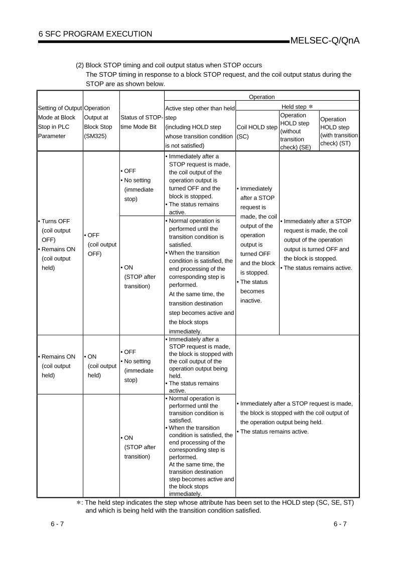
6 - 7 6 - 7
MELSEC-Q/QnA6 SFC PROGRAM EXECUTION
(2) Block STOP timing and coil output status when STOP occursThe STOP timing in response to a block STOP request, and the coil output status during theSTOP are as shown below.
OperationHeld step Setting of Output
Mode at BlockStop in PLCParameter
OperationOutput atBlock Stop(SM325)
Status of STOP-time Mode Bit
Active step other than heldstep(including HOLD stepwhose transition conditionis not satisfied)
Coil HOLD step(SC)
OperationHOLD step(withouttransitioncheck) (SE)
OperationHOLD step(with transitioncheck) (ST)
• OFF• No setting
(immediatestop)
• Immediately after aSTOP request is made,the coil output of theoperation output isturned OFF and theblock is stopped.
• The status remainsactive.
• Turns OFF(coil outputOFF)
• Remains ON(coil outputheld)
• OFF(coil outputOFF)
• ON(STOP aftertransition)
• Normal operation isperformed until thetransition condition issatisfied.
• When the transitioncondition is satisfied, theend processing of thecorresponding step isperformed.At the same time, thetransition destinationstep becomes active andthe block stopsimmediately.
• Immediatelyafter a STOPrequest ismade, the coiloutput of theoperationoutput isturned OFFand the blockis stopped.
• The statusbecomesinactive.
• Immediately after a STOPrequest is made, the coiloutput of the operationoutput is turned OFF andthe block is stopped.
• The status remains active.
• Remains ON(coil outputheld)
• ON(coil outputheld)
• OFF• No setting
(immediatestop)
• Immediately after aSTOP request is made,the block is stopped withthe coil output of theoperation output beingheld.
• The status remainsactive.
• ON(STOP aftertransition)
• Normal operation isperformed until thetransition condition issatisfied.
• When the transitioncondition is satisfied, theend processing of thecorresponding step isperformed.At the same time, thetransition destinationstep becomes active andthe block stopsimmediately.
• Immediately after a STOP request is made,the block is stopped with the coil output ofthe operation output being held.
• The status remains active.
: The held step indicates the step whose attribute has been set to the HOLD step (SC, SE, ST)and which is being held with the transition condition satisfied.

6 - 8 6 - 8
MELSEC-Q/QnA6 SFC PROGRAM EXECUTION
POINTSM325 is turned ON/OFF by the system according to the parameter setting when the CPUmodule switches from STOP to RUN.
Parameter Setting SM325Turns OFF (coil output OFF) OFFRemains ON (coil output held) ON
By turning ON/OFF SM325 in the user program, the output mode at block STOP can bechanged independently of the parameter setting.

6 - 9 6 - 9
MELSEC-Q/QnA6 SFC PROGRAM EXECUTION
6.3.2 Restarting a stopped block
The methods for restarting a block which has been temporarily stopped during SFC programprocessing are described below.
(1) Restarting block processingThe methods for restarting a block which has been temporarily stopped are shown below.
Restart Method Operation Description Remarks
Restart by SFCcontrol instruction
• Processing of the specified block is restarted byan SFC control instruction at a step (operationoutput) or sequence program outside thestopped block.
Condition
* “m” is the block No.
RSTART BLm
• Convenient for returning to automatic operationwhen the manual control END signal is outputat the temporary STOP.
RESTART by SFCinformation device
• The execution of the corresponding block isrestarted by forcibly turning ON the "blockSTOP/RESTART bit", which was set to eachblock as the SFC information device, in theprogram or peripheral device.
• Convenient for confirming operation by stepcontrol at debugging and test operations,because block processing can be restartedfrom a peripheral device without requiring aprogram.
(2) Active step when restart occursThe step which is active when a block is restarted varies according to the status which existedwhen the STOP occurred, as shown below.
Operation Output at Block RESTARTHeld step
Output Mode Setting atBlock STOP
Active step other thanheld step
(including HOLD stepwhose transitioncondition is not
satisfied)
Coil HOLD step (SC)Operation HOLD step
(without transitioncheck) (SE)
Operation HOLD step(with transition check)
(ST)
At coil output OFF
• Restart disabled.(Since the step isdeactivated at a blockSTOP)
At coil output HOLD
• Returns to normaloperation.
• Restarts as held.
• Restarts the executionof the operation outputin a HOLD status.
• Restarts the operationoutput in a HOLDstatus.
• Also checks thetransition condition.
: The held step indicates the step whose attribute has been set to the HOLD step (SC, SE, ST)and which is being held with the transition condition satisfied.
POINTSM325 is turned ON/OFF by the system according to the parameter setting when the CPUmodule switches from STOP to RUN.
Parameter Setting SM325Turns OFF (coil output OFF) OFFRemains ON (coil output held) ON
By turning ON/OFF SM325 in the user program, the output mode at block STOP can bechanged independently of the parameter setting.

6 - 10 6 - 10
MELSEC-Q/QnA6 SFC PROGRAM EXECUTION
6.4 Step START (Activate) and END (Deactivate) Methods
6.4.1 Step START (activate) methods
There are the following step START (activation) methods.
Step START(Activation) Method Operation Remarks
Step START by SFCdiagram symbol
• The corresponding step is automatically started whenthe preceding transition condition is satisfied.
ConditionTRAN
Started when condition is satisfied.
• Basic operation of SFC program
Step START by SFCcontrol instruction
• The specified step is forcibly started by the SFCcontrol instruction at the step (operation output) of theSFC program or in another sequence program.
ConditionSET BLm\Sn
* “m” is the block No., “n” is the step No.
Condition
* “n” is the step No.
SET Sn
• Jump to other blocks can be made.• When the block of the destination step is
inactive, a block forced START is madefrom the specified step.
• When there are initial steps in multipleblocks, a selection START is made.
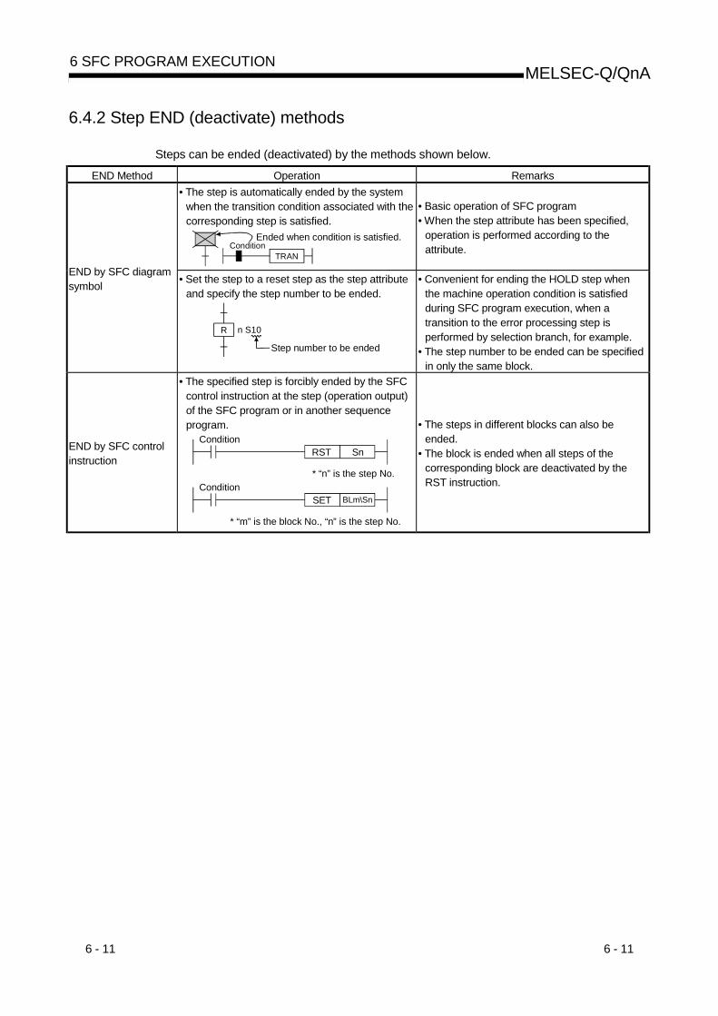
6 - 11 6 - 11
MELSEC-Q/QnA6 SFC PROGRAM EXECUTION
6.4.2 Step END (deactivate) methods
Steps can be ended (deactivated) by the methods shown below.
END Method Operation Remarks• The step is automatically ended by the system
when the transition condition associated with thecorresponding step is satisfied.
Ended when condition is satisfied.Condition
TRAN
• Basic operation of SFC program• When the step attribute has been specified,
operation is performed according to theattribute.
END by SFC diagramsymbol • Set the step to a reset step as the step attribute
and specify the step number to be ended.
n S10
Step number to be ended
R
• Convenient for ending the HOLD step whenthe machine operation condition is satisfiedduring SFC program execution, when atransition to the error processing step isperformed by selection branch, for example.
• The step number to be ended can be specifiedin only the same block.
END by SFC controlinstruction
• The specified step is forcibly ended by the SFCcontrol instruction at the step (operation output)of the SFC program or in another sequenceprogram.
ConditionSET BLm\Sn
* “m” is the block No., “n” is the step No.
Condition
* “n” is the step No.
RST Sn
• The steps in different blocks can also beended.
• The block is ended when all steps of thecorresponding block are deactivated by theRST instruction.
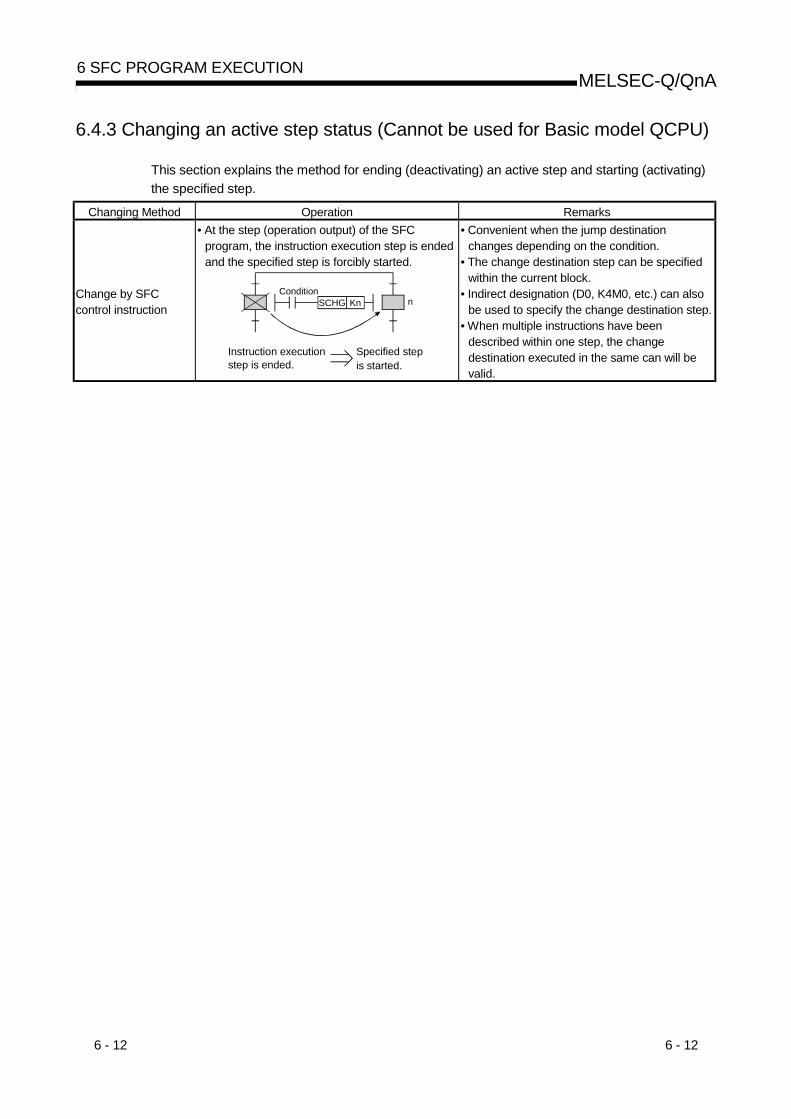
6 - 12 6 - 12
MELSEC-Q/QnA6 SFC PROGRAM EXECUTION
6.4.3 Changing an active step status (Cannot be used for Basic model QCPU)
This section explains the method for ending (deactivating) an active step and starting (activating)the specified step.
Changing Method Operation Remarks
Change by SFCcontrol instruction
• At the step (operation output) of the SFCprogram, the instruction execution step is endedand the specified step is forcibly started.
Instruction execution step is ended.
Specified step is started.
nCondition
SCHG Kn
• Convenient when the jump destinationchanges depending on the condition.
• The change destination step can be specifiedwithin the current block.
• Indirect designation (D0, K4M0, etc.) can alsobe used to specify the change destination step.
• When multiple instructions have beendescribed within one step, the changedestination executed in the same can will bevalid.

6 - 13 6 - 13
MELSEC-Q/QnA6 SFC PROGRAM EXECUTION
6.5 Operation Methods for Continuous Transition
If "with continuous transition" is set, whether a continuous transition will be performed or not canbe selected at each step using the continuous transition disable flag (SM324).
(1) Processing performed when continuous transition disable flag is not used
SFC Program With Continuous Transition Without Continuous Transition(Block n)
S0
TranSM400
TranSM400
TranSM400
S1
S2
S3
When the corresponding block becomes active,the processings of all steps are executed in thesame scan, and end step processing isperformed to deactivate the block.
• When the corresponding block becomesactive, steps are executed in a 1-step-per-scan format.
• The end step processing is performed in thethird scan to deactivate the block.
(2) Processing performed when continuous transition disable flag is used
SFC Program With Continuous Transition Without Continuous Transition
(Block n)S0
TranSM400 SM324
TranSM400 SM324
TranSM400 SM324
S1
S2
S3
• When the corresponding block becomesactive, execution proceeds to step 1 sinceSM324 is ON.When execution proceeds to step 1, theprocessing of the first scan is ended sinceSM324 turns OFF.
• In the second scan, execution proceeds tostep 2 since SM324 turns ON again.When execution proceeds to step 2, SM324turns OFF.Since the transition condition of step 2 doesnot have the contact of SM324, a transitionoccurs and the end step processing isperformed to deactivate the block.
• When the corresponding block becomesactive, steps are executed in a 1-step-per-scan format independently of whether SM324is present or absent.
• The end step processing is performed in thethird scan to deactivate the block.
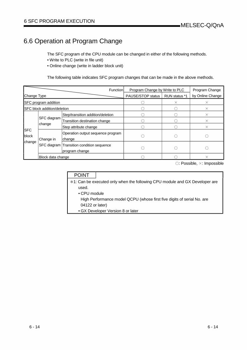
6 - 14 6 - 14
MELSEC-Q/QnA6 SFC PROGRAM EXECUTION
6.6 Operation at Program Change
The SFC program of the CPU module can be changed in either of the following methods.• Write to PLC (write in file unit)• Online change (write in ladder block unit)
The following table indicates SFC program changes that can be made in the above methods.
Program Change by Write to PLCFunctionChange Type PAUSE/STOP status RUN status *1
Program Changeby Online Change
SFC program additionSFC block addition/deletion
Step/transition addition/deletionTransition destination change
SFC diagramchange
Step attribute changeOperation output sequence programchangeChange in
SFC diagram Transition condition sequenceprogram change
SFCblockchange
Block data change: Possible, : Impossible
POINT1: Can be executed only when the following CPU module and GX Developer are
used.• CPU module
High Performance model QCPU (whose first five digits of serial No. are04122 or later)
• GX Developer Version 8 or later

6 - 15 6 - 15
MELSEC-Q/QnA6 SFC PROGRAM EXECUTION
(1) Operation at program change made by write to PLC(a) When program was written with CPU module in PAUSE/STOP status
1) Program start after write to PLCAn initial start is performed independently of the SFC start mode setting (initialstart/resume start).Depending on the SFC program change, however, an initial start is not made but aresume start may be made at the resume start setting.Refer to Section 4.7.1 for details of the SFC program start mode.
2) Device status at program startAt a program start after write to PLC, the CPU module devices operate as described inthe following table depending on the setting of the SFC device clear mode setting flag(SM326).
OperationSM326
Step relay Other than step relay
OFF Turned ON/OFF by the system.SFC program is executed after alldevices have been cleared.
ON Turned ON/OFF by the system.SFC program is executed with all devicesheld.
POINTThe setting of SM326 is valid only when an SFC program exists after write to PLC.When sequence program and/or parameter write is performed, the setting ofSM326 is also valid.(The setting of SM326 is ignored when only the data other than the SFC program,sequence program and parameters are written.)
(b) When program was written with CPU module in RUN status1) Program start after write to PLC
An initial start is performed independently of the SFC start mode setting (initialstart/resume start).Refer to Section 4.7.1 for details of the SFC program start mode.
2) Device status at program startThe SFC program is executed with all devices held.
(2) Program change by online change(a) Program start after write to PLC
When program change is made by online change, a resume start is performedindependently of the SFC start mode setting.
(b) Device status at program startThe SFC program is executed with all devices held.
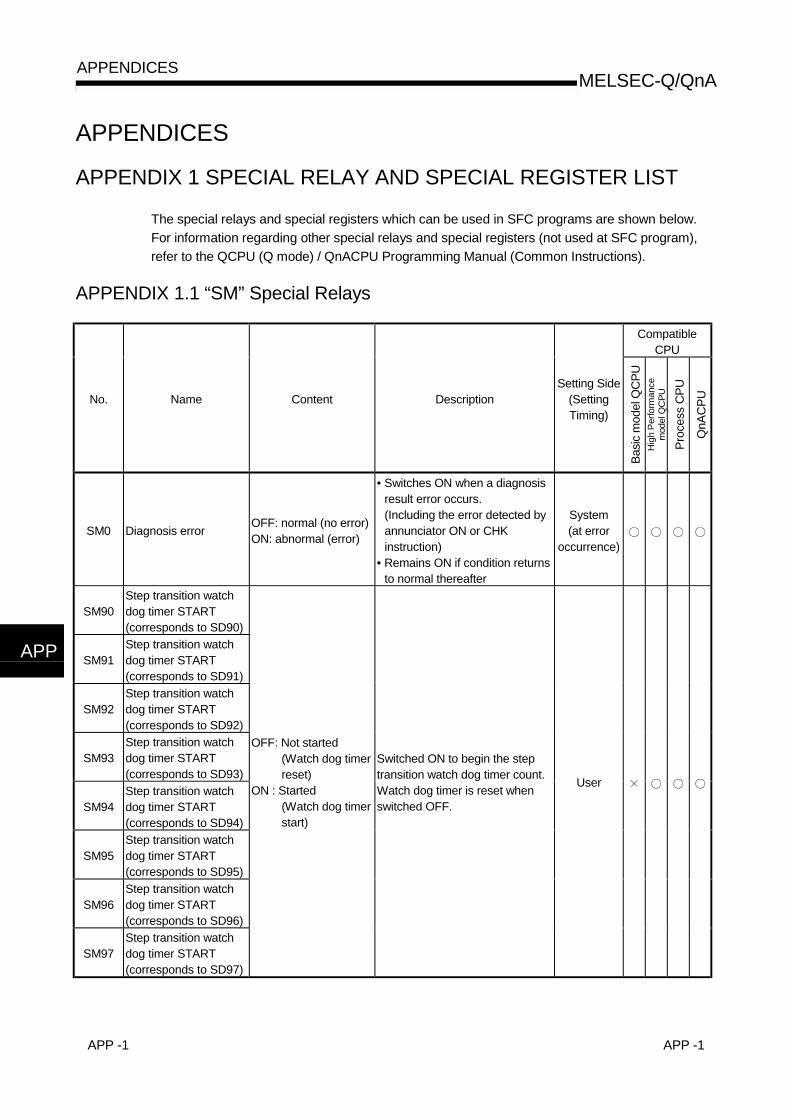
APP -1 APP -1
MELSEC-Q/QnAAPPENDICES
APPENDICES
APPENDIX 1 SPECIAL RELAY AND SPECIAL REGISTER LIST
The special relays and special registers which can be used in SFC programs are shown below.For information regarding other special relays and special registers (not used at SFC program),refer to the QCPU (Q mode) / QnACPU Programming Manual (Common Instructions).
APPENDIX 1.1 “SM” Special Relays
CompatibleCPU
No. Name Content DescriptionSetting Side
(SettingTiming)
Basic
mod
el Q
CPU
Hig
h Pe
rform
ance
mod
el Q
CPU
Proc
ess
CPU
QnA
CPU
SM0 Diagnosis error OFF: normal (no error)ON: abnormal (error)
• Switches ON when a diagnosisresult error occurs.(Including the error detected byannunciator ON or CHKinstruction)
• Remains ON if condition returnsto normal thereafter
System(at error
occurrence)
SM90Step transition watchdog timer START(corresponds to SD90)
SM91Step transition watchdog timer START(corresponds to SD91)
SM92Step transition watchdog timer START(corresponds to SD92)
SM93Step transition watchdog timer START(corresponds to SD93)
SM94Step transition watchdog timer START(corresponds to SD94)
SM95Step transition watchdog timer START(corresponds to SD95)
SM96Step transition watchdog timer START(corresponds to SD96)
SM97Step transition watchdog timer START(corresponds to SD97)
OFF: Not started(Watch dog timerreset)
ON : Started(Watch dog timerstart)
Switched ON to begin the steptransition watch dog timer count.Watch dog timer is reset whenswitched OFF.
User
APP
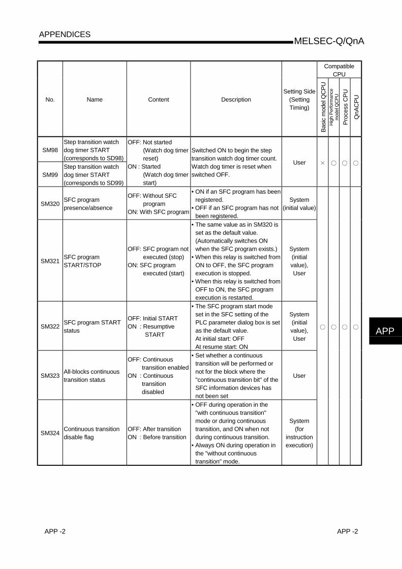
APP -2 APP -2
MELSEC-Q/QnAAPPENDICES
CompatibleCPU
No. Name Content DescriptionSetting Side
(SettingTiming)
Basic
mod
el Q
CPU
Hig
h Pe
rform
ance
mod
el Q
CPU
Proc
ess
CPU
QnA
CPU
SM98Step transition watchdog timer START(corresponds to SD98)
SM99Step transition watchdog timer START(corresponds to SD99)
OFF: Not started(Watch dog timerreset)
ON : Started(Watch dog timerstart)
Switched ON to begin the steptransition watch dog timer count.Watch dog timer is reset whenswitched OFF.
User
SM320 SFC programpresence/absence
OFF: Without SFCprogram
ON: With SFC program
• ON if an SFC program has beenregistered.
• OFF if an SFC program has notbeen registered.
System(initial value)
SM321 SFC programSTART/STOP
OFF: SFC program notexecuted (stop)
ON: SFC programexecuted (start)
• The same value as in SM320 isset as the default value.(Automatically switches ONwhen the SFC program exists.)
• When this relay is switched fromON to OFF, the SFC programexecution is stopped.
• When this relay is switched fromOFF to ON, the SFC programexecution is restarted.
System(initialvalue),User
SM322 SFC program STARTstatus
OFF: Initial STARTON : Resumptive
START
• The SFC program start modeset in the SFC setting of thePLC parameter dialog box is setas the default value.At initial start: OFFAt resume start: ON
System(initialvalue),User
SM323 All-blocks continuoustransition status
OFF: Continuoustransition enabled
ON : Continuoustransitiondisabled
• Set whether a continuoustransition will be performed ornot for the block where the"continuous transition bit" of theSFC information devices hasnot been set
User
SM324 Continuous transitiondisable flag
OFF: After transitionON : Before transition
• OFF during operation in the"with continuous transition"mode or during continuoustransition, and ON when notduring continuous transition.
• Always ON during operation inthe "without continuoustransition" mode.
System(for
instructionexecution)
APP

APP -3 APP -3
MELSEC-Q/QnAAPPENDICES
CompatibleCPU
No. Name Content DescriptionSetting Side
(SettingTiming)
Basic
mod
el Q
CPU
Hig
h Pe
rform
ance
mod
el Q
CPU
Proc
ess
CPU
QnA
CPU
SM325 Operation output atblock STOP
OFF: Coil output OFFON : Coil output ON
Select whether the coil output ofthe active step will be held or notat a block STOP.
• As the default value, OFF whencoil output OFF is selected forthe output mode at parameterblock STOP, and ON when coiloutput held is selected.
• When this relay is OFF, the coiloutputs are all turned OFF.
• When this relay is ON, the coiloutputs are held.
System(initialvalue),User
SM326 SFC device clear mode OFF: Clear deviceON : Preserves device
• Select the device status whenthe CPU is switched from STOPto program write to RUN. (Alldevices except the step relay)
User
SM327 Output mode at endstep execution
OFF: HOLD stepoutput OFF
ON: HOLD step outputheld
• When this relay is OFF, the SC,SE or ST step that was heldwhen a transition condition hadbeen satisfied turns OFF the coiloutput when the end step isreached.
User
SM328 Clear processing modeat arrival at end step
OFF: Clear processingis performed
ON: Clear processingis not performed
Select whether clear processingwill be performed or not whenactive steps other than thoseheld exist in the block at the timeof arrival at the end step.
• When this relay is OFF, theactive steps are all endedforcibly to end the block.
• When this relay is ON, theexecution of the block iscontinued as is.
• When no active steps other thanthose held exist at the time ofarrival at the end step, the heldsteps are all ended to end theblock.
User

APP -4 APP -4
MELSEC-Q/QnAAPPENDICES
CompatibleCPU
No. Name Content DescriptionSetting Side
(SettingTiming)
Basic
mod
el Q
CPU
Hig
h Pe
rform
ance
mod
el Q
CPU
Proc
ess
CPU
QnA
CPU
SM331 Normal SFC programexecution status
OFF: Not executedON: Being executed
• Indicates whether the normalSFC program is being executedor not.
• Used as an execution interlockof the SFC control instruction.
S (statuschange)
SM332
Program executionmanagement SFCprogram executionstatus
OFF: Not executedON: Being executed
• Indicates whether the programexecution management SFCprogram is being executed ornot.
• Used as an execution interlockof the SFC control instruction.
S (statuschange)
∗
SM820 Step trace ready status OFF: Not readyON : Ready
• Switches ON when a “ready”status is established after steptrace registration.
System(status
change)
SM821 Step trace START OFF: Trace STOPON : Trace START
• Designates the step traceSTART/STOP status.When ON : Step trace function
is started.When OFF: Step trace function
is stopped.If switched OFFduring a traceexecution, thetrace operation isstopped.
User
SM822 Step trace executionflag
OFF: Trace inactiveON : Trace active
• ON when step trace executionis in progress, and OFF whentracing is completed or stopped.
System(status
change)
SM823 Post-trigger step traceOFF: TriggerunsatisfiedON : Trigger satisfied
• Switches ON when a triggercondition is satisfied at any ofthe blocks where the step tracefunction is being executed.
System(status
change)
SM824 Post-trigger step trace
OFF: Block withunsatisfied triggerexists
ON : Triggers at allblocks aresatisfied
• Switches ON when triggerconditions are satisfied at allblocks where the step tracefunction is being executed.
System(status
change)
SM825 Step trace END flag OFF: Trace STARTON : Trace END
• Switches ON when step tracingis completed at all the specifiedblocks, and switches OFF whenstep tracing begins.
System(status
change)
*: Applicable to the one whose first five digits of serial No. are "04122" or later.

APP -5 APP -5
MELSEC-Q/QnAAPPENDICES
APPENDIX 1.2 “SD” Special RegistersCompatible
CPU
No. Name Content DescriptionSetting Side
(SettingTiming)
Basic
mod
el Q
CPU
Hig
h Pe
rform
ance
mod
elQ
CPU
Proc
ess
CPU
QnA
CPU
SD0 Diagnosis error Diagnosis errorcode
• The error code at occurrence of a diagnosiserror is stored in BIN code.
“4 ” for errors originating at a SFCprogram.
• This data is the same as the latestinformation in the fault history.
System(at error
occurrence)
SD1
• The year (last 2 digits of year) and monthwhen the SD0 data was updated are storedin 2-digit BCD code.
Year (0 to 99) Month (1 to 12)
b15 b7 b0b8to to(Example) : October, 1995 H9510
SD2
• The day and hour when the SD0 data wasupdated are stored in 2-digit BCD code
Day (1 to 31) Hour (0 to 23)b15 b7 b0b8to to (Example)
: 10 p.m. on 25th H2510
SD3
Diagnosis erroroccurrencetime
Diagnosis erroroccurrence time
• The clock data when an SD0 update occursis stored.
Minutes (0 to 59)
b15 b7 b0b8to to (Example) : 35 min. 48 sec. (past the hour) H3548
Seconds (0 to 59)
System(at error
occurrence)
SD4Errorinformationclassification
Error informationclassificationcode
The classification codes for judgment of whaterror information is stored in the commoninformation (SD5 to SD15) and individualinformation (SD16 to SD26) are stored.
Individual informationcategory codes
Common informationcategory codes
b15 b7 b0b8to to
• The following codes are stored into thecommon information classification code.• 0: None• 1: Module No./PLC No./base No.• 2: File name/drive name• 3: Time (set value)• 4: Program error location
• The following codes are stored into thecommon information classification code.• 0: None• 1: (Empty)• 2: File name/drive name• 3: Time (set value)• 4: Program error location• 5: Parameter No.• 6: Annunciator (F) No.
System(at error
occurrence)

APP -6 APP -6
MELSEC-Q/QnAAPPENDICES
CompatibleCPU
No. Name Content DescriptionSetting Side
(SettingTiming)
Basic
mod
el Q
CPU
Hig
h Pe
rform
ance
mod
el Q
CPU
Proc
ess
CPU
QnA
CPU
SD5
SD6
SD7
SD8
SD9
SD10
SD11
SD12
SD13
SD14
SD15
Error“commoninformation”2
Error“commoninformation”
• The common information corresponding to the error code(SD0) is stored.
• There are the following four different stored informationtypes.
1) Module No.
SD5SD6SD7SD8SD9SD10SD11SD12SD13SD14SD15
MeaningSlot No./Base No.
I/O No.
(Vacant)
Number1 2
3
1: In the case of a multiple PLC system, the slot No. orPLC No. is stored depending on the error thatoccurred. Slot 0 in the multiple PLC system indicatesthe slot on the right of the right-end CPU module.(For which is stored, refer to the corresponding errorcode.)PLC No. 1: 1, PLC No. 2: 2, PLC No. 3: 3
2: When 255 is stored into SD5, it indicates that aninstruction or like was executed for the module afterthe last mountable slot.
3: When 0FFFFH is stored into SD6 (I/O No.), itindicates that the I/O number cannot be identified,e.g. I/O No. overlapping in the I/O assignmentparameter. Therefore, identify the error location usingSD5.
2) File name/drive name
Number
SD5SD6SD7SD8SD9SD10SD11SD12SD13SD14SD15
MeaningDrive
2EH(.)
File name(ASCII code: 8 characters)
(Vacant)
41H(A) 4DH(M)4EH(N) 49H(I)20H(SP) 20H(SP)20H(SP) 20H(SP)51H(Q) 2EH(.)47H(G) 50H(P)
b15 to b8 b7 to b0
(Example)File name=MAIN. QPG
Extension(ASCII code: 3 characters)
4
System
(at erroroccurrence)
: For the extension, refer to REMARKS on the next page.

APP -7 APP -7
MELSEC-Q/QnAAPPENDICES
CompatibleCPU
No. Name Content DescriptionSetting Side
(SettingTiming)
Basic
mod
el Q
CPU
Hig
h Pe
rform
ance
mod
el Q
CPU
Proc
ess
CPU
QnA
CPU
SD5
SD6
SD7
SD8
SD9
SD10
SD11
SD12
SD13
SD14
SD15
Error“commoninformation”
Error“commoninformation”
3) Time (set value)NumberSD5SD6SD7SD8SD9
SD10SD11SD12SD13SD14SD15
MeaningTime : 1 µs units (0 to 999 µs)
(Vacant)
Time : 1 ms units (0 to 65535 ms)
4) Program error locationNumberSD5SD6SD7SD8SD9
SD10SD11SD12SD13SD14SD15
Meaning
2EH(.)
File name(ASCII code: 8 characters)
Extension(ASCII code: 3 characters)
PatternBlock No.
Step No./transition No.Sequence step No. (L)Sequence step No. (H)
4
5
5: Pattern data definitions
to
SFC block specified (1)/not specified (0)(Not used)
000 0(Bit number)15 14 34 12 0to
SFC step specified (1)/not specified (0)SFC transition specified (1)/not specified (0)
System
(at erroroccurrence)
REMARK
4: For the extension, refer to REMARKS on the next page.
SD10 SD11
First 8 bits Last 8 bits First 8 bitsExtension
NameFile Type
51H 50H 41H QPA Parameter51H 50H 47H QPG Sequence program/SFC program51H 43H 44H QCD Device comment51H 44H 52H QDR File register

APP -8 APP -8
MELSEC-Q/QnAAPPENDICES
CompatibleCPU
No. Name Content DescriptionSetting Side
(SettingTiming)
Basic
mod
el Q
CPU
Hig
h Pe
rform
ance
mod
el Q
CPU
Proc
ess
CPU
QnA
CPU
SD16
SD17
SD18
SD19
SD20
SD21
SD22
SD23
SD24
SD25
Errorindividualinformation
Errorindividualinformation
• The individual information corresponding to the error code(SD0) is stored.
• There are the following six different stored information types.1) File name/drive name
Number
SD16SD17SD18SD19SD20SD21SD22SD23SD24SD25SD26
MeaningDrive
2EH(.)
File name(ASCII code: 8 characters)
(Vacant)
41H(A)4EH(N)20H(SP)20H(SP)51H(Q)47H(G)
4DH(M)49H(I)
20H(SP)20H(SP)2EH(.)50H(P)
b15 to b8 b7 to b0
(Example)File name=MAIN. QPG
Extension(ASCII code: 3 characters)
4
2) Time (measured value)NumberSD16SD17SD18SD19SD20SD21SD22SD23SD24SD25SD26
MeaningTime : 1 µs units (0 to 999 µs)
(Vacant)
Time : 1 ms units (0 to 65535 ms)
3) Program error locationNumberSD16SD17SD18SD19SD20SD21SD22SD23SD24SD25SD26
Meaning
2EH(.)
File name(ASCII code: 8 characters)
Extension(ASCII code: 3 characters)
PatternBlock No.
Step No./transition No.Sequence step No. (L)Sequence step No. (H)
5
4
5: Pattern data definitionsto
SFC block specified (1)/not specified (0)(Not used)
000 0(Bit number)15 14 34 12 0to
SFC step specified (1)/not specified (0)SFC transition specified (1)/not specified (0)
4) Parameter No. 5) Annunciator No. 6) Intelligent function module parameter error
NumberSD16SD17SD18SD19SD20SD21SD22SD23SD24SD25SD26
MeaningNo.
(Vacant)
NumberSD16SD17SD18SD19SD20SD21SD22SD23SD24SD25SD26
MeaningParameter No.
(Vacant)
Number
SD16SD17
SD18SD19SD20SD21SD22SD23SD24SD25SD26
Meaning
(Vacant)
Parameter No.Error code for intelligentfunction module
6 6
6: For details of the parameter No., refer to the user'smanual (function explanation, program fundamentals)of the used CPU module.
System(at error
occurrence)

APP -9 APP -9
MELSEC-Q/QnAAPPENDICES
CompatibleCPU
No. Name Content DescriptionSetting Side
(SettingTiming)
Basic
mod
el Q
CPU
Hig
h Pe
rform
ance
mod
elQ
CPU
Proc
ess
CPU
QnA
CPU
SD90 Correspondingto SM90
SD91 Correspondingto SM91
SD92 Correspondingto SM92
SD93 Correspondingto SM93
SD94 Correspondingto SM94
SD95 Correspondingto SM95
SD96 Correspondingto SM96
SD97 Correspondingto SM97
SD98 Correspondingto SM98
SD99 Correspondingto SM99
Timer set valueand F No. attime-out
• Set the set time of the step transition watchdog timer and the annunciator No. (F No.)that will turn ON at time-out of the watch dogtimer.
b15 b7 b0b8
F number setting (0 to 255)
Timer time limit setting (1 to 255 sec: (1-second units))
to to
• The timer starts when any of SM90 to SM99is turned ON during an active step, and theset annunciator (F) turns ON if the transitioncondition following the corresponding step isnot satisfied within the timer time limit.
System(at error
occurrence)

APP -10 APP -10
MELSEC-Q/QnAAPPENDICES
APPENDIX 2 MELSAP-II AND MELSAP3 COMPARISON
Compared to MELSAP-II, the improved MELSAP3 has additional functions which facilitate the useof SFC programs. MELSAP-II and MELSAP3 are compared below.
MELSAP3 improvements and added functions1) SFC program control by instructions
Using SFC control instructions at a sequence program, the SFC program status can bechecked, and blocks/steps can be forcibly started and ended.
2) Additional step attributesMELSAP3 offers many more step attributes, such as the operation HOLD step, reset step,block START step (without END wait), etc.Moreover, machine control by SFC program has been made easier by improvements suchas the step follow-up function (activates multiple steps in a series within a single block), anda control function which allows transitions (at block START requests) without waiting for ablock END status at the START destination block (asynchronous control of the STARTsource and destination blocks).
3) Expanded memory capacityIn addition to an increased number of steps and branches per block, the capacity of stepand transition condition programs has been increased to 4k sequence steps in order tomake programming easier.
4) Substantial block informationThe amount of block information has been increased, permitting operations such as acontinuous transition designation in 1-block units, and a STOP timing selection (“immediateSTOP” or “STOP when transition condition is satisfied”) for block STOP requests.Furthermore, the additional block information simplifies operation by permitting a blockSTART and END to be executed from a single device.
5) Increased processing speed reduces system processing timeThe SFC program's system processing time has been reduced, resulting in reduced tacttimes through the efficient combination of the SFC program functions.
6) Improved operability of SFC software packageTroublesome menu switching operations have been eliminated by permitting SFCcomments, steps and transition condition programs to be created concurrently with SFCladder creation.Moreover, the SFC diagram cut and paste function, and block unit registration/utilizationhave been simplified.
For reference purposes, comparisons of the major MELSAP-II andMELSAP3 functions areshown in the following pages.
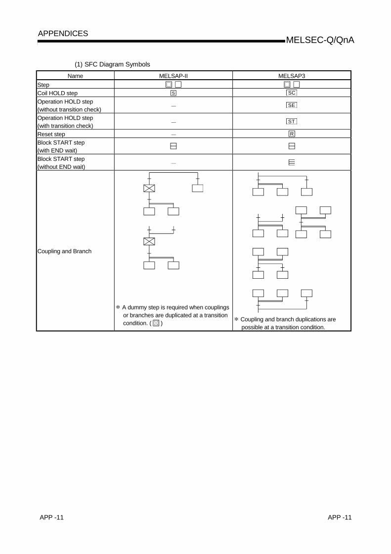
APP -11 APP -11
MELSEC-Q/QnAAPPENDICES
(1) SFC Diagram Symbols
Name MELSAP-II MELSAP3Step Coil HOLD step S SC
Operation HOLD step(without transition check)
SE
Operation HOLD step(with transition check)
ST
Reset step R
Block START step(with END wait)Block START step(without END wait)
Coupling and Branch
A dummy step is required when couplingsor branches are duplicated at a transitioncondition. ( ) Coupling and branch duplications are
possible at a transition condition.

APP -12 APP -12
MELSEC-Q/QnAAPPENDICES
(2) SFC Control InstructionsThe SFC control instruction shown below are available at MELSAP3.MELSAP-II has no SFC control instructions.
CompatibleCPU
Name Ladder Expression Function
Basic
mod
el Q
CPU
Hig
h Pe
rform
ance
mod
el Q
CPU
Proc
ess
CPU
QnA
CPU
LD, AND, OR,LDI, ANI, ORI Sn 1
Step status (active/inactive)check instruction LD, AND, OR,
LDI, ANI, ORI BLm\Sn
• Executes a check to determine ifa specified step at a specifiedblock is active or inactive.
LD, AND, OR,LDI, ANI, ORI TRn 1
Forced transition checkinstruction LD, AND, OR,
LDI, ANI, ORI BLn\TRn
• Checks a specified step in aspecified block to determine if thetransition condition (by transitioncontrol instruction) for that stepwas satisfied forcibly or not.
Block operation statuscheck instruction
LD, AND, OR,LDI, ANI, ORI BLm • Checks a specified block to
determine if it is active or inactive.
MOV (P) K4Sn D 1MOV (P) BLm\K4Sn D
DMOV (P) K8Sn D 1DMOV (P) BLm\K8Sn D
BMOV (P) K4Sn D Kn 1
Active steps batchreadout instruction
BMOV (P) BLm\K4Sn D Kn
• Active steps in a specified blockare read to a specified device asbit information.
Block START instruction SET BLm
• A specified block is forciblystarted (activated) independently,and is executed from its initialstep.
Block END instruction RST BLm • A specified block is forcibly ended(deactivated).
Block STOP instruction PAUSE BLm • A specified block is temporarilystopped.
Block restart instruction RSTART BLm
• The temporary stop status at aspecified block is canceled, withoperation resuming from theSTOP step.
SET Sn 1
SET BLm\Sn
• A specified block is forciblystarted (activated) independently,and is executed from a specifiedstep.
RST Sn 1
RST BLm\Sn
• A specified step in a specifiedblock is forcibly ended(deactivated).
Step control instruction
SCHG D 2• The instruction execution step is
deactivated, and a specified stepis activated.
SET TRmn 1
SET BLm\TRn
• A specified transition condition ata specified block is forciblysatisfied.
RST TRn 1Transition control instruction
RST BLm\TRn
• The forced transition at aspecified transition condition in aspecified block is canceled.
Block switching instruction BRSET D• Blocks subject to the “ 1” SFC
control instruction are designated.

APP -13 APP -13
MELSEC-Q/QnAAPPENDICES
(3) Block/Step START, END, and STOP Methods
MELSAP-II MELSAP3By SFC Diagram
SymbolBy Block
InformationBy SFC Diagram
SymbolBy Block
InformationBy SFC control
InstructionBlock START(with END check) m m
Block START(without ENDcheck)
Block active bit ON mBlock
START/END bitON
SET BLmSET BLm/Sn
Block END Block clear bitON → OFF
BlockSTART/END bit
OFFRST BLm
Block STOP Block STOP bit ONBlock
STOP/RESTARTbit ON
PAUSE BLm
Block restart(STOP cancel)
Block STOP bitOFF
BlockSTOP/RESTART
bit OFFRSTART BLm
Step STARTBlock active No.register(at block
STOP only)
SET SnSET BLm/Sn
Step END R SnRST Sn
RST BLm/SnActive step change SCHG Sn
Active step forcedtransition
SET TRnSET BLm/TRn
Forced transitioncancel
RST TRnRST BLm/Sn
STOP timing atblock STOPrequest
Not specified(immediate STOP)
Specified by blockSTOP mode bit
(“immediate STOP”or “STOP after
transition conditionis satisfied”)
: The Basic model QCPU cannot use active step change, active step forced transition, andforced transition cancel.

APP -14 APP -14
MELSEC-Q/QnAAPPENDICES
(4) Basic model QCPU(a) SFC Program Specifications
Item MELSAP-II MELSAP3
Capacity Max. 14k bytes(A1SHCPU)
Max. 14kbytes(Q01CPU)
Number of blocks Max. 256 blocks Max. 128 blocks
Number of SFC steps Max. of 255 steps per blockMax. of 1024 steps (total for all
blocks), max. of 128 steps per blockNumber of branches Max. of 22 Max. of 32
Number of concurrentlyactive steps
Max. of 1024 steps (total for allblocks),max. of 22 steps per block
Max. of 1024 steps (total for allblocks), max. of 128 steps per block
(including HOLD steps)Number of operationoutput sequence steps Max. of 255 sequence steps Max. of 2k steps per block, no limit
per step
SFC program
Number of transitioncondition sequencesteps
Max. of 255 sequence steps Max. of 2k steps per block, no limitper step
Step transition watchdog timer function Function exists (8 timers) None
(b) System processing times of main CPU module types
MELSAP3MELSAP-II
Basic model QCPUItemA1S(J)H A2SH Q00JCPU Q00CPU Q01CPU
Active block processing 63.6 µs 48.2 µs 41.9 µs 35.5 µs 27.3 µsInactive block processing 3.2 µs 2.4 µs 10.5 µs 8.8 µs 6.8 µsNonexistent block processing 3.0 µs 2.3 µs 1.1 µs 0.9 µs 0.7 µsActive step processing 91.5 µs 69.3 µs 31.6 µs 26.7 µs 20.5 µsTransition condition processing associatedwith active step 26.9 µs 20.4 µs 10.2 µs 8.7 µs 6.7 µs
With HOLD stepdesignation 9.9 µs 7.5 µs 216.0 µs 182.8 µs 140.6 µsTransition
condition-satisfiedstep processing Normal step 35.9 µs 27.2 µs 263.5 µs 222.9 µs 171.5 µsSFC END processing 200.8 µs 152.1 µs 66.8 µs 56.5 µs 43.5 µs

APP -15 APP -15
MELSEC-Q/QnAAPPENDICES
(5) High Performance model QCPU, Process CPU, QnACPU(a) SFC Program Specifications
Item MELSAP-II MELSAP3
CapacityMax. 58k bytes
(A3N, A3A, A3U, A4U CPU)(main program only)
Max. 124kbytes(Q4ACPU)
Max. 252kbytes(Q25HCPU, Q25PHCPU)
Number of blocks Max. 256 blocks Max. 320 blocks
Number of SFC steps Max. of 255 steps per blockMax. of 8192 steps (total for all
blocks), max. of 512 steps per blockNumber of branches Max. of 22 Max. of 32
Number of concurrentlyactive steps
Max. of 1024 steps (total for allblocks),max. of 22 steps per block
Max. of 1280 steps (total for allblocks), max. of 256 steps per block
(including HOLD steps)Number of operationoutput sequence steps Max. of 255 sequence steps Max. of 2k steps per block, no limit
per step 1
SFC program
Number of transitioncondition sequencesteps
Max. of 255 sequence stepsMax. 2k steps for one block
No restriction on each transitioncondition
Step transition watchdog timer function Function exists (8 timers) Function exists(10 timers)
(b) System processing times of main CPU module types
MELSAP-II MELSAP3High Performance
Model QCPUProcess
CPUItem A3ACPU (F)A3UCPUA4UCPU
AnNCPU-FA1SCPU
Q4ACPUQ2ASHCPU
QnCPU QnHCPU QnPHCPUActive block processing 57.0 µs 260.0 µs 30.6 µs 33.7 µs 14.5 µs 14.5 µsInactive block processing 14.0 µs 45.0 µs 10.7 µs 12.0 µs 5.2 µs 5.2 µsNonexistent block processing 4.0 µs 25.0 µs 4.6 µs 4.1 µs 1.8 µs 1.8 µsActive step processing 49.5 µs 355.0 µs 23.2 µs 24.5 µs 10.6 µs 10.6 µsTransition condition processing associatedwith active step 29.5 µs 100.0 µs 9.4 µs 10.0 µs 4.3 µs 4.3 µs
Without HOLD stepdesignation 2.4 µs 13.5 µs 137.2 µs 130.4 µs 56.2 µs 56.2 µsTransition
condition-satisfiedstep processing With HOLD step
designation 17.0 µs 60.0 µs 122.5 µs 119.4 µs 51.5 µs 51.5 µs
SFC END processing 195.0 µs 285.0 µs 89.7 µs 108.2 µs 46.6 µs 46.6 µs1: When "Peripheral" is selected for note editing with the operation output (Peripheral Note),
up to 2k steps may not be secured for one block. When note editing is not performed or"Unite" is selected for note editing (United Note), up to 2k steps can be secured for oneblock.

APP -16 APP -16
MELSEC-Q/QnAAPPENDICES
APPENDIX 3 Restrictions on Basic Model QCPU and Replacement Methods
This section explains the restrictions on use of a SFC program with the Basic model QCPU.
(1) Function comparison
Item Basic Mode QCPUHigh Performance Model QCPU
Process CPUQnACPU
ReplacementMethod
Step transition watchdog timer Not provided Provided Appendix 3.1Operation mode at blockdouble START
Not provided(Fixed to "WAIT")
Provided
Operation mode fortransition to active step(at step double START)
Not provided(Fixed to "TRANSFER")
ProvidedSFCoperationmode setting
Fixed-cycle executionblock setting
Not provided Provided Appendix 3.2
LD TRnAND TRnOR TRnLDI TRnANI TRnORI TRnLD BL/TRnAND BL/TRnOR BL/TRnLDI BL/TRnANI BL/TRn
Forcedtransitioncheckinstruction
ORI BL/TRn
Not provided Provided
Active stepchangeinstruction
SCHG (D) Not provided Provided Appendix 3.4
SET TRnSET BL/TRnRST TRn
Transitioncontrolinstruction
RSE BL/TRn
Not provided Provided Appendix 3.3
SFC controlinstruction
Blockswitchinginstruction
BRSET (S) Not provided Provided
SFC program for program executionmanagement
Not provided Provided
Program execution type settingNot provided
(Fixed to "scan execution type")Provided
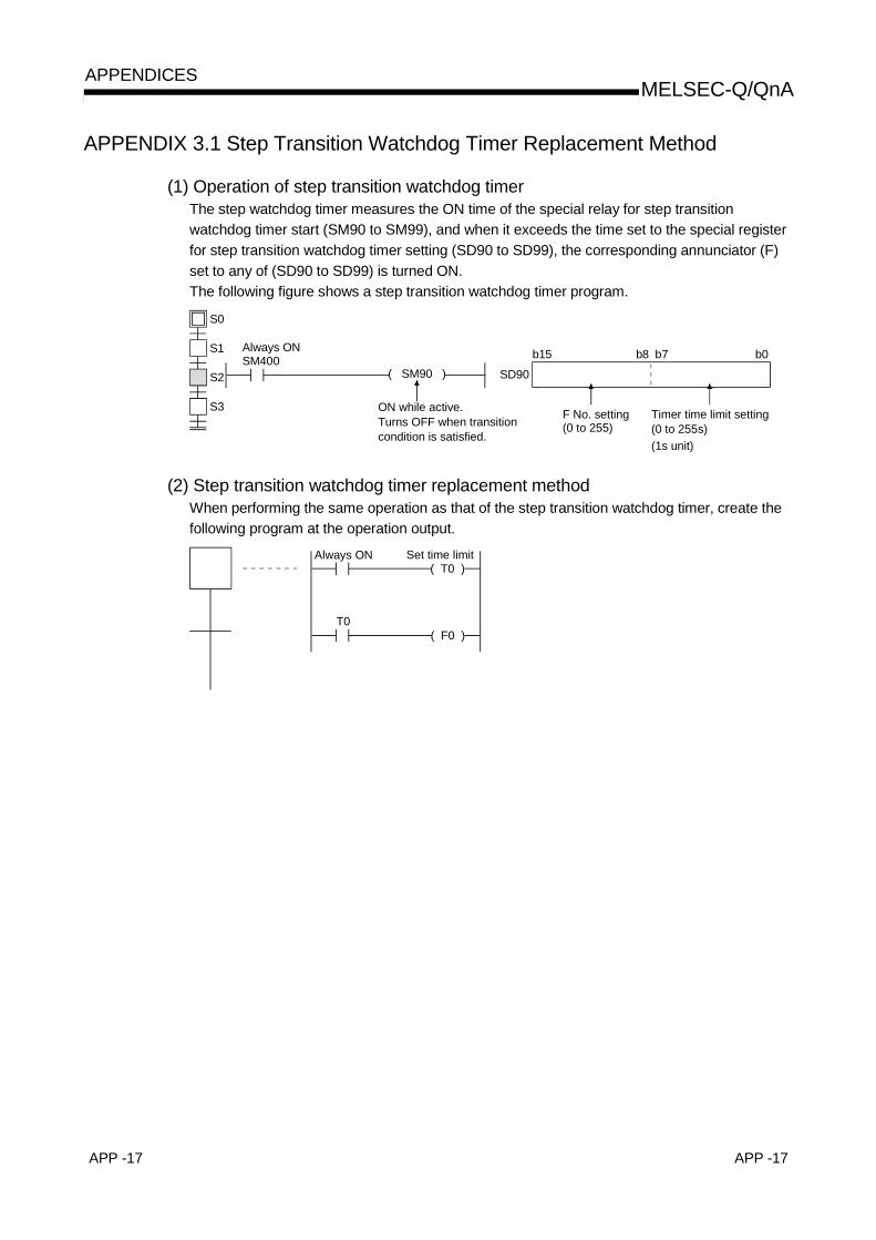
APP -17 APP -17
MELSEC-Q/QnAAPPENDICES
APPENDIX 3.1 Step Transition Watchdog Timer Replacement Method
(1) Operation of step transition watchdog timerThe step watchdog timer measures the ON time of the special relay for step transitionwatchdog timer start (SM90 to SM99), and when it exceeds the time set to the special registerfor step transition watchdog timer setting (SD90 to SD99), the corresponding annunciator (F)set to any of (SD90 to SD99) is turned ON.The following figure shows a step transition watchdog timer program.
S0
S1
S2
S3
( SM90 )
Always ONSM400
ON while active.Turns OFF when transition condition is satisfied.
b15 b8 b7 b0SD90
F No. setting(0 to 255)
Timer time limit setting(0 to 255s)(1s unit)
(2) Step transition watchdog timer replacement methodWhen performing the same operation as that of the step transition watchdog timer, create thefollowing program at the operation output.
( T0 )Always ON Set time limit
( F0 )T0

APP -18 APP -18
MELSEC-Q/QnAAPPENDICES
APPENDIX 3.2 Fixed-Cycle Execution Block Replacement Method
(1) Operation of fixed-cycle execution blockA fixed-cycle execution block is executed in each scan where the specified execution intervalhas elapsed.The following figure shows the operation performed when blocks 0, 1, 2, 10 and 11 are usedand blocks 10 and 11 are set as the fixed-cycle execution blocks.
1 scan 1 scan 1 scan 1 scan
Execution interval
End
proc
essi
ng
End
proc
essi
ng
End
proc
essi
ng
End
proc
essi
ng
Blocks 0, 1, 2
executed
Blocks 0, 1, 2
executed
Blocks 0, 1, 2
executed
Blocks 0, 1, 2
executed
Blocks 10, 11
executed
Blocks 10, 11
executed
Execution interval
(2) Fixed-cycle execution block replacement methodWhen the execution interval measured by the timer in the sequence program reaches the settime, the specified block is activated by the STOP/RESTART bit.When the set time is not reached, the block is in a stop status.To hold the output also when the block is in a stop status, select "Change OUT instruction inspecified block to SET instruction" or "Coil output held for stop-time output mode".
Tn
RST Tn
SET BLmSM402
SM400
Tn
Set interval
Corresponding block STOP/ RESTART bit

APP -19 APP -19
MELSEC-Q/QnAAPPENDICES
APPENDIX 3.3 Forced Transition Bit (TRn) Replacement Method
(1) Operation by forced transition bitThe forced transition bit forcibly satisfies a transition condition.When the forced transition bits are used, the preset input conditions can be ignored and thetransition conditions can be satisfied in due order.
M0SET BL0\TR0
M10RST BL0\TR0
M1SET BL0\TR1
M11RST BL0\TR1
Sequence program SFC program
User-set transition condition
S0
t0
S1
t1
TRAN
TRAN
User-set transition condition
(2) Forced transition bit replacement methodDescribe any bit device in the transition condition, where it is desired to cause a forcedtransition, under the OR condition and turn ON the bit device described under the ORcondition to cause a forced transition.
SFC program
User-set transition condition
S0
t0
S1
t1
TRANM0
TRANM1
User-set transition condition
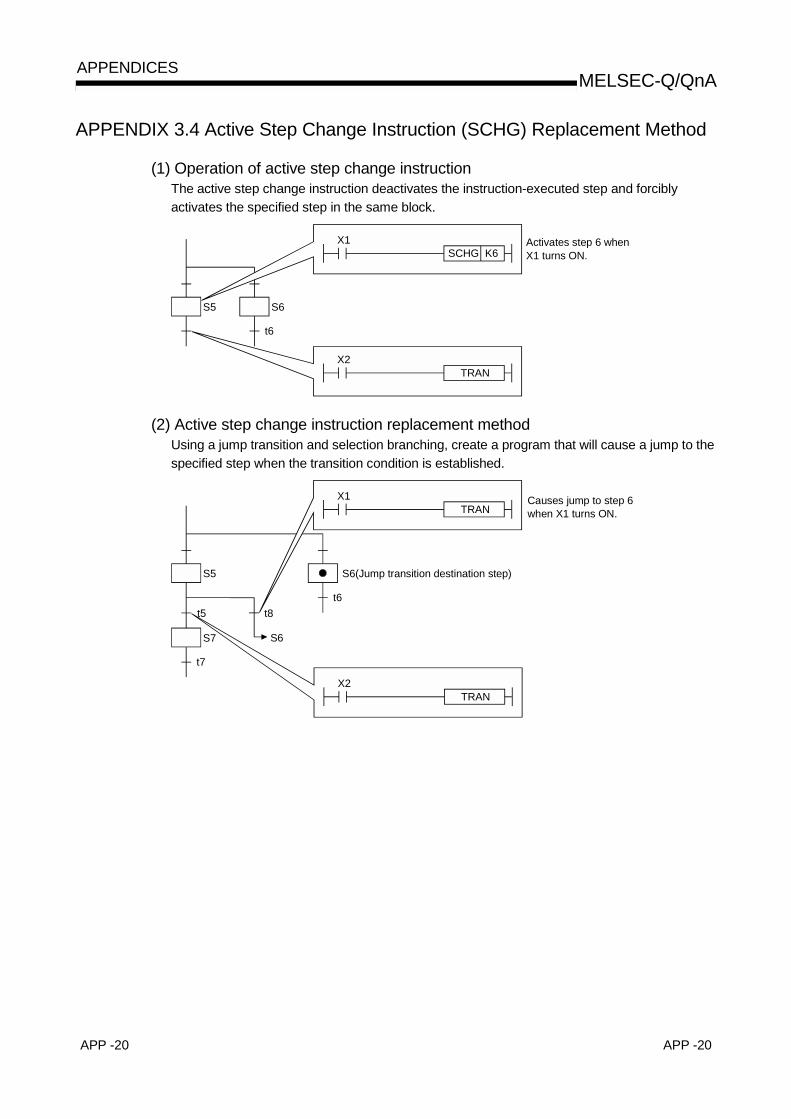
APP -20 APP -20
MELSEC-Q/QnAAPPENDICES
APPENDIX 3.4 Active Step Change Instruction (SCHG) Replacement Method
(1) Operation of active step change instructionThe active step change instruction deactivates the instruction-executed step and forciblyactivates the specified step in the same block.
S5 S6
t6
X1SCHG K6
X2TRAN
Activates step 6 when X1 turns ON.
(2) Active step change instruction replacement methodUsing a jump transition and selection branching, create a program that will cause a jump to thespecified step when the transition condition is established.
S6(Jump transition destination step)
t6
S5
X1TRAN
X2TRAN
S7
t7
S6
t8t5
Causes jump to step 6 when X1 turns ON.

WARRANTY
Please confirm the following product warranty details before starting use.
1. Gratis Warranty Term and Gratis Warranty RangeIf any faults or defects (hereinafter "failure") found to be the responsibility of Mitsubishi occurs during use of the productwithin the gratis warranty term, the product shall be repaired at no cost via the dealer or Mitsubishi Service Company.Note that if repairs are required at a site overseas, on a detached island or remote place, expenses to dispatch anengineer shall be charged for.[Gratis Warranty Term]
The gratis warranty term of the product shall be for one year after the date of purchase or delivery to a designatedplace.Note that after manufacture and shipment from Mitsubishi, the maximum distribution period shall be six (6) months, andthe longest gratis warranty term after manufacturing shall be eighteen (18) months. The gratis warranty term of repairparts shall not exceed the gratis warranty term before repairs.
[Gratis Warranty Range](1) The range shall be limited to normal use within the usage state, usage methods and usage environment, etc.,
which follow the conditions and precautions, etc., given in the instruction manual, user's manual and caution labelson the product.
(2) Even within the gratis warranty term, repairs shall be charged for in the following cases.1. failure occurring from inappropriate storage or handling, carelessness or negligence by the user. Failure caused
by the user's hardware or software design.2. Failure caused by unapproved modifications, etc., to the product by the user.3. When the Mitsubishi product is assembled into a user's device, failure that could have been avoided if functions
or structures, judged as necessary in the legal safety measures the user's device is subject to or as necessaryby industry standards, had been provided.
4. Failure that could have been avoided if consumable parts (battery, backlight, fuse, etc.) designated in theinstruction manual had been correctly serviced or replaced.
5. Failure caused by external irresistible forces such as fires or abnormal voltages, and failure caused by forcemajeure such as earthquakes, lightning, wind and water damage.
6. Failure caused by reasons unpredictable by scientific technology standards at time of shipment from Mitsubishi.7. Any other failure found to not be the responsibility of Mitsubishi or the user.
2. Onerous repair term after discontinuation of production(1) Mitsubishi shall accept onerous product repairs for seven (7) years after production of the product is discontinued.
Discontinuation of production shall be notified with Mitsubishi Technical Bulletins, etc.(2) Product supply (including repair parts) is not possible after production is discontinued.
3. Overseas serviceOverseas, repairs shall be accepted by Mitsubishi's local overseas FA Center. Note that the repair conditions at each FACenter may differ.
4. Exclusion of chance loss and secondary loss from warranty liabilityRegardless of the gratis warranty term, Mitsubishi shall not be liable for compensation to damages caused by any causefound not to be the responsibility of Mitsubishi, chance losses, lost profits incurred to the user by failures in Mitsubishiproducts, damages and secondary damages caused from special reasons regardless of Mitsubishi's expectations,compensation for accidents, and compensation for damages to products other than Mitsubishi products and other duties.
5. Changes in product specificationsThe specifications given in the catalogs, manuals or technical documents are subject to change without prior notice.
6. Product application(1) In using the Mitsubishi MELSEC programmable logic controller, the usage conditions shall be that the application will
not lead to a major accident even if any problem or fault should occur in the programmable logic controller device, andthat backup and fail-safe functions are systematically provided outside of the device for any problem or fault.
(2) The Mitsubishi general-purpose programmable logic controller has been designed and manufactured for applicationsin general industries, etc. Thus, applications in which the public could be affected such as in nuclear power plants andother power plants operated by respective power companies, and applications in which a special quality assurancesystem is required, such as for each Japan Railways company or the Department of Defense shall be excluded fromthe programmable logic controller applications.Note that even with these applications, if the user approves that the application is to be limited and a special quality isnot required, application shall be possible.When considering use in aircraft, medical applications, railways, incineration and fuel devices, manned transportdevices, equipment for recreation and amusement, and safety devices, in which human life or assets could be greatlyaffected and for which a particularly high reliability is required fin terms of safety and control system, please consultwith Mitsubishi and discuss the required specifications.

P
Programming Manual
Mitsubishi Programmable Logic Controller
Specifications subject to change without notice.
MODEL
MODELCODE
QNA/QCPU-P(SF)-E
13JF60
SH(NA)-080041-D(0303)MEE
QCPU(Q Mode)/QnACPU
Programming Manual(SFC)
QCPU(Q Mode)/QnACPU
(SFC)
QC
PU
(Q M
ode)/QnA
CP
U P
rogramm
ing Manual(S
FC
)
When exported from Japan, this manual does not require application to theMinistry of Economy, Trade and Industry for service transaction permission.
HEAD OFFICE : 1-8-12, OFFICE TOWER Z 14F HARUMI CHUO-KU 104-6212,JAPANNAGOYA WORKS : 1-14 , YADA-MINAMI 5 , HIGASHI-KU, NAGOYA , JAPAN
R