qd8 quik-drive tap-changer reversing switch movable ...€¦ · and replacement of the reversing...
TRANSCRIPT
QD8 Quik-Drive Tap-Changer Reversing Switch Movable Contact Assembly Kit 5740785B13 and Reversing Switch Neutral Stationary Contact Assembly Kit 5791646A48
Installation Instructions
COOPER POWERSERIES
Voltage RegulatorsMN225035EN
Effective June 2016New Issue
ii INSTALLATION INSTRUCTIONS MN225035EN June 2016
DISCLAIMER OF WARRANTIES AND LIMITATION OF LIABILITY
The information, recommendations, descriptions and safety notations in this document are based on Eaton Corporation’s (“Eaton”) experience and judgment and may not cover all contingencies. If further information is required, an Eaton sales office should be consulted. Sale of the product shown in this literature is subject to the terms and conditions outlined in appropriate Eaton selling policies or other contractual agreement between Eaton and the purchaser.
THERE ARE NO UNDERSTANDINGS, AGREEMENTS, WARRANTIES, EXPRESSED OR IMPLIED, INCLUDING WARRANTIES OF FITNESS FOR A PARTICULAR PURPOSE OR MERCHANTABILITY, OTHER THAN THOSE SPECIFICALLY SET OUT IN ANY EXISTING CONTRACT BETWEEN THE PARTIES. ANY SUCH CONTRACT STATES THE ENTIRE OBLIGATION OF EATON. THE CONTENTS OF THIS DOCUMENT SHALL NOT BECOME PART OF OR MODIFY ANY CONTRACT BETWEEN THE PARTIES.
In no event will Eaton be responsible to the purchaser or user in contract, in tort (including negligence), strict liability or other-wise for any special, indirect, incidental or consequential damage or loss whatsoever, including but not limited to damage or loss of use of equipment, plant or power system, cost of capital, loss of power, additional expenses in the use of existing power facilities, or claims against the purchaser or user by its customers resulting from the use of the information, recommendations and descriptions contained herein. The information contained in this manual is subject to change without notice.
iiiINSTALLATION INSTRUCTIONS MN225035EN June 2016
Contents
DISCLAIMER OF WARRANTIES AND LIMITATION OF LIABILITY . . . . . . . . . . . . . . . . . . . . . . . . . . . . . . . . . . . II
SAFETY FOR LIFE . . . . . . . . . . . . . . . . . . . . . . . . . . . . . . . . . . . . . . . . . . . . . . . . . . . . . . . . . . . . . . . . . . . . . . . . . IV
SAFETY INFORMATION . . . . . . . . . . . . . . . . . . . . . . . . . . . . . . . . . . . . . . . . . . . . . . . . . . . . . . . . . . . . . . . . . . . . IVSafety instructions . . . . . . . . . . . . . . . . . . . . . . . . . . . . . . . . . . . . . . . . . . . . . . . . . . . . . . . . . . . . . . . . . . . . . . . . . . . . . . iv
PRODUCT INFORMATION . . . . . . . . . . . . . . . . . . . . . . . . . . . . . . . . . . . . . . . . . . . . . . . . . . . . . . . . . . . . . . . . . . . 1Introduction . . . . . . . . . . . . . . . . . . . . . . . . . . . . . . . . . . . . . . . . . . . . . . . . . . . . . . . . . . . . . . . . . . . . . . . . . . . . . . . . . . . .1
Read this manual first . . . . . . . . . . . . . . . . . . . . . . . . . . . . . . . . . . . . . . . . . . . . . . . . . . . . . . . . . . . . . . . . . . . . . . . . . . . .1
Acceptance and initial inspection . . . . . . . . . . . . . . . . . . . . . . . . . . . . . . . . . . . . . . . . . . . . . . . . . . . . . . . . . . . . . . . . . . .1
Handling and storage . . . . . . . . . . . . . . . . . . . . . . . . . . . . . . . . . . . . . . . . . . . . . . . . . . . . . . . . . . . . . . . . . . . . . . . . . . . . .1
Quality standards. . . . . . . . . . . . . . . . . . . . . . . . . . . . . . . . . . . . . . . . . . . . . . . . . . . . . . . . . . . . . . . . . . . . . . . . . . . . . . . .1
Additional information . . . . . . . . . . . . . . . . . . . . . . . . . . . . . . . . . . . . . . . . . . . . . . . . . . . . . . . . . . . . . . . . . . . . . . . . . . . .1
Parts supplied . . . . . . . . . . . . . . . . . . . . . . . . . . . . . . . . . . . . . . . . . . . . . . . . . . . . . . . . . . . . . . . . . . . . . . . . . . . . . . . . . .1
Tools required . . . . . . . . . . . . . . . . . . . . . . . . . . . . . . . . . . . . . . . . . . . . . . . . . . . . . . . . . . . . . . . . . . . . . . . . . . . . . . . . . .1
INSTALLATION PROCEDURE . . . . . . . . . . . . . . . . . . . . . . . . . . . . . . . . . . . . . . . . . . . . . . . . . . . . . . . . . . . . . . . . 2Removal . . . . . . . . . . . . . . . . . . . . . . . . . . . . . . . . . . . . . . . . . . . . . . . . . . . . . . . . . . . . . . . . . . . . . . . . . . . . . . . . . . . . . . .2
Reassembly . . . . . . . . . . . . . . . . . . . . . . . . . . . . . . . . . . . . . . . . . . . . . . . . . . . . . . . . . . . . . . . . . . . . . . . . . . . . . . . . . . . .4
PLACING TAP-CHANGER INTO NEUTRAL . . . . . . . . . . . . . . . . . . . . . . . . . . . . . . . . . . . . . . . . . . . . . . . . . . . . . . 7
iv
QD8 Quik-Drive Tap-Changer Assembly Kits 5740785B13 and 5791646A48
INSTALLATION INSTRUCTIONS MN225035EN June 2016
The instructions in this manual are not intended as a substitute for proper training or adequate experience in the safe operation of the equipment described. Only competent technicians who are familiar with this equipment should install, operate, and service it.
A competent technician has these qualifications:
• Is thoroughly familiar with these instructions.
• Is trained in industry-accepted high and low-voltage safe operating practices and procedures.
• Is trained and authorized to energize, de-energize, clear, and ground power distribution equipment.
• Is trained in the care and use of protective equipment such as arc flash clothing, safety glasses, face shield, hard hat, rubber gloves, clampstick, hotstick, etc.
Following is important safety information. For safe installation and operation of this equipment, be sure to read and understand all cautions and warnings.
Safety instructionsFollowing are general caution and warning statements that apply to this equipment. Additional statements, related to specific tasks and procedures, are located throughout the manual.
Safety for life!
SAFETYFOR LIFE
!SAFETYFOR LIFE
Eaton meets or exceeds all applicable industry standards relating to product safety in its Cooper Power™ series products. We actively promote safe practices in the use and maintenance of our products through our service literature, instructional training programs, and the continuous efforts of all Eaton employees involved in product design, manufacture, marketing, and service.
We strongly urge that you always follow all locally approved safety procedures and safety instructions when working around high voltage lines and equipment, and support our “Safety For Life” mission.
Safety information
DANGERHazardous voltage. Contact with hazardous voltage will cause death or severe personal injury. Follow all locally approved safety procedures when working around high- and low-voltage lines and equipment. G103.3
WARNING Before installing, operating, maintaining, or testing this equipment, carefully read and understand the contents of this manual. Improper operation, handling or maintenance can result in death, severe personal injury, and equipment damage. G101.0
WARNING This equipment is not intended to protect human life. Follow all locally approved procedures and safety practices when installing or operating this equipment. Failure to comply can result in death, severe personal injury and equipment damage. G102.1
WARNING Power distribution and transmission equipment must be properly selected for the intended application. It must be installed and serviced by competent personnel who have been trained and understand proper safety procedures. These instructions are written for such personnel and are not a substitute for adequate training and experience in safety procedures. Failure to properly select, install or maintain power distribution and transmission equipment can result in death, severe personal injury, and equipment damage. G122.2
This manual may contain four types of hazard statements:
DANGER Indicates an imminently hazardous situation which, if not avoided, will result in death or serious injury.
WARNING Indicates a potentially hazardous situation which, if not avoided, could result in death or serious injury.
CAUTION Indicates a potentially hazardous situation which, if not avoided, may result in minor or moderate injury.
CAUTIONIndicates a potentially hazardous situation which, if not avoided, may result in equipment damage only.
Hazard Statement Definitions
1
QD8 Quik-Drive Tap-Changer Assembly Kits 5740785B13 and 5791646A48
INSTALLATION INSTRUCTIONS MN225035EN June 2016
Product information
IntroductionEaton’s Cooper Power™ series QD8 Quik-Drive tap-changer reversing switch movable contact assembly and the reversing switch neutral stationary contact assembly kits and installation instructions provides instructions for removal and replacement of the reversing switch movable contact assembly and reversing switch neutral stationary contact for the polymer model of the QD8 Quik-Drive tap-changer.
Read this manual firstRead and understand the contents of this manual and follow all locally approved procedures and safety practices before installing or operating this equipment.
Acceptance and initial inspectionEach kit is in good condition when accepted by the carrier for shipment. Upon receipt, inspect the shipping container for signs of damage. Unpack the kit and inspect it thoroughly for damage incurred during shipment. If damaged is discovered, file a claim with the carrier immediately.
Handling and storageBe careful during handling and storage of the kit to minimize the possibility of damage. If the kit is to be stored for any length of time prior to installation, provide a clean, dry storage area.
Quality standardsISO 9001 Certified Quality Management System
Additional informationThese instructions cannot cover all details or variations in the equipment, procedures, or process described nor provide directions for meeting every possible contingency during installation, operation, or maintenance. For additional information, contact your representative.
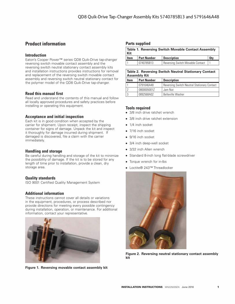
Figure 1. Reversing movable contact assembly kit
Parts suppliedTable 1. Reversing Switch Movable Contact Assembly KitItem Part Number Description Qty1 0740785B13 Reversing Switch Movable Contact 1
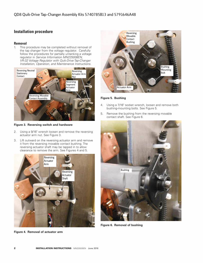
Table 2. Reversing Switch Neutral Stationary Contact Assembly KitItem Part Number Description1 0791646A48 Reversing Switch Neutral Stationary Contact
2 0800005001Z Jam Nut
3 0892568A02 Belleville Washer
Tools required ● 3/8 inch drive ratchet wrench
● 3/8 inch drive ratchet extension
● 1/4 inch socket
● 7/16 inch socket
● 9/16 inch socket
● 3/4 inch deep-well socket
● 3/32 inch Allen wrench
● Standard 8-inch long flat-blade screwdriver
● Torque wrench for in-lbs
● Loctite® 243™ Threadlocker
Figure 2. Reversing neutral stationary contact assembly kit
2
QD8 Quik-Drive Tap-Changer Assembly Kits 5740785B13 and 5791646A48
INSTALLATION INSTRUCTIONS MN225035EN June 2016
Installation procedure
Removal1. This procedure may be completed without removal of
the tap changer from the voltage regulator. Carefully follow the procedures for partially untanking a voltage regulator in Service Information MN225008EN, VR-32 Voltage Regulator with Quik-Drive Tap-Changer Installation, Operation, and Maintenance Instructions.
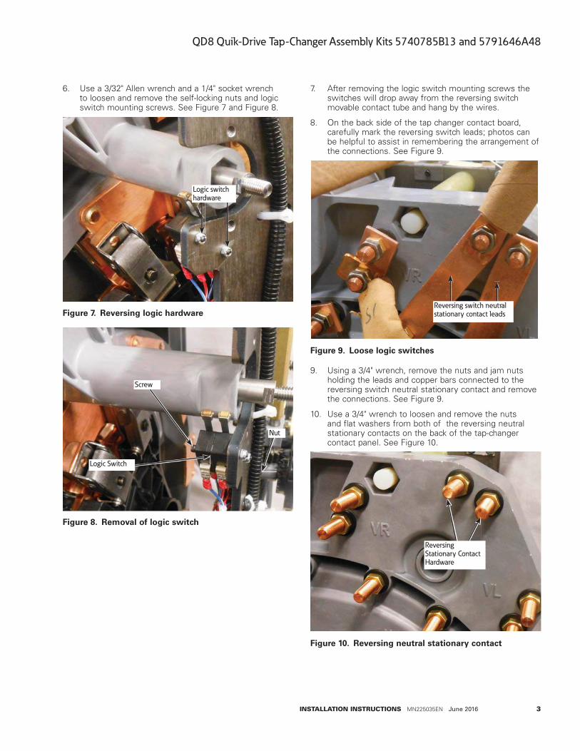
Reversing NeutralStationaryContact
Reversing MovableContact Assembly
ReversingSegmentActuatorArm
ReversingActuator ArmNut
Figure 3. Reversing switch and hardware
2. Using a 9/16" wrench loosen and remove the reversing actuator arm nut. See Figure 3.
3. Lift outward on the reversing actuator arm and remove it from the reversing movable contact bushing. The reversing actuator shaft may be tapped in to allow clearance to remove the arm. See Figures 4 and 5.
ReversingActuatorArm
ReversingActuatorShaft
Figure 4. Removal of actuator arm
ReversingMovableContactBushing
Actuator Arm
BushingMountingBolt
Figure 5. Bushing
4. Using a 7/16" socket wrench, loosen and remove both bushing-mounting bolts. See Figure 5.
5. Remove the bushing from the reversing movable contact shaft. See Figure 6.
Bushing
Figure 6. Removal of bushing
3
QD8 Quik-Drive Tap-Changer Assembly Kits 5740785B13 and 5791646A48
INSTALLATION INSTRUCTIONS MN225035EN June 2016
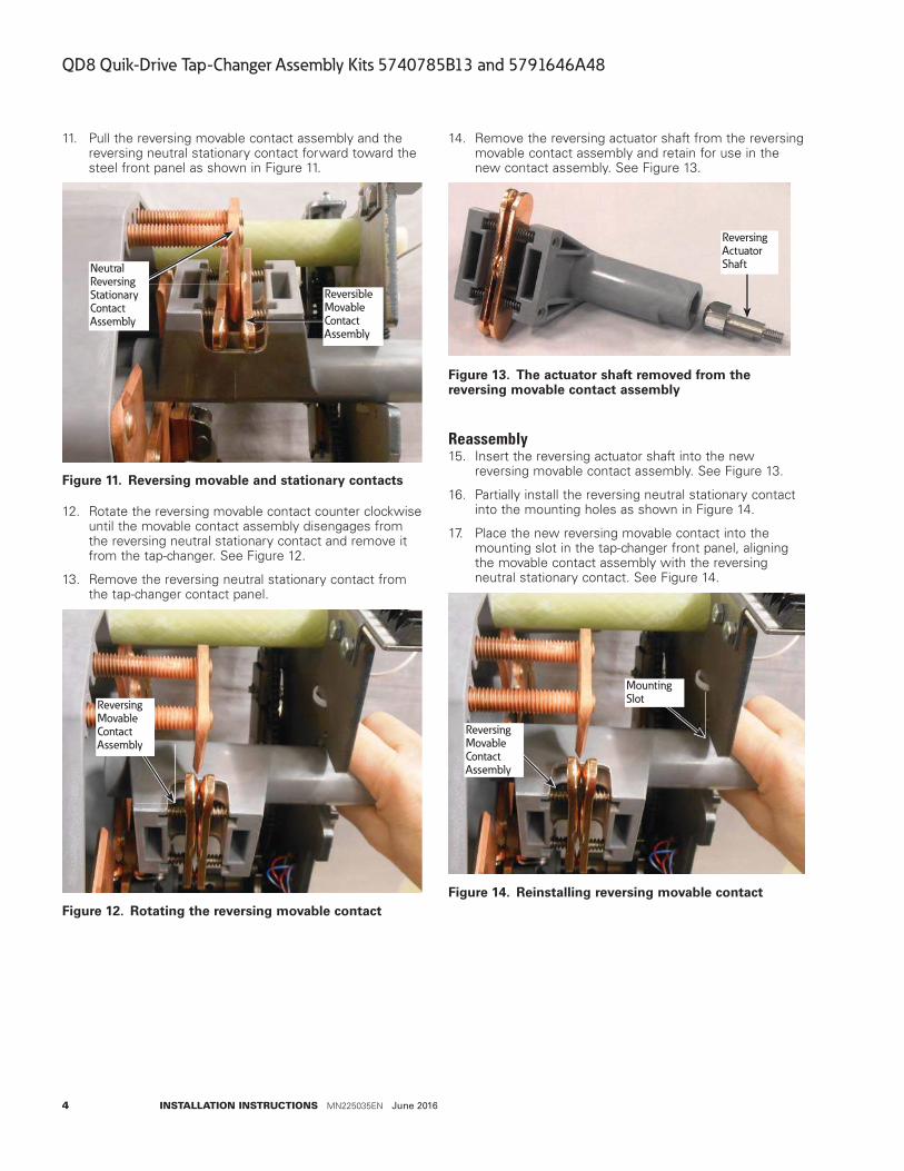
6. Use a 3/32" Allen wrench and a 1/4" socket wrench to loosen and remove the self-locking nuts and logic switch mounting screws. See Figure 7 and Figure 8.
Logic switchhardware
Figure 7. Reversing logic hardware
Screw
Logic Switch
Nut
Figure 8. Removal of logic switch
7. After removing the logic switch mounting screws the switches will drop away from the reversing switch movable contact tube and hang by the wires.
8. On the back side of the tap changer contact board, carefully mark the reversing switch leads; photos can be helpful to assist in remembering the arrangement of the connections. See Figure 9.
Reversing switch neutralstationary contact leads
Figure 9. Loose logic switches
9. Using a 3/4" wrench, remove the nuts and jam nuts holding the leads and copper bars connected to the reversing switch neutral stationary contact and remove the connections. See Figure 9.
10. Use a 3/4" wrench to loosen and remove the nuts and flat washers from both of the reversing neutral stationary contacts on the back of the tap-changer contact panel. See Figure 10.
ReversingStationary ContactHardware
Figure 10. Reversing neutral stationary contact
4
QD8 Quik-Drive Tap-Changer Assembly Kits 5740785B13 and 5791646A48
INSTALLATION INSTRUCTIONS MN225035EN June 2016
11. Pull the reversing movable contact assembly and the reversing neutral stationary contact forward toward the steel front panel as shown in Figure 11.
NeutralReversingStationaryContactAssembly
ReversibleMovableContactAssembly
Figure 11. Reversing movable and stationary contacts
12. Rotate the reversing movable contact counter clockwise until the movable contact assembly disengages from the reversing neutral stationary contact and remove it from the tap-changer. See Figure 12.
13. Remove the reversing neutral stationary contact from the tap-changer contact panel.
ReversingMovableContactAssembly
Figure 12. Rotating the reversing movable contact
14. Remove the reversing actuator shaft from the reversing movable contact assembly and retain for use in the new contact assembly. See Figure 13.
ReversingActuatorShaft
Figure 13. The actuator shaft removed from the reversing movable contact assembly
Reassembly15. Insert the reversing actuator shaft into the new
reversing movable contact assembly. See Figure 13.
16. Partially install the reversing neutral stationary contact into the mounting holes as shown in Figure 14.
17. Place the new reversing movable contact into the mounting slot in the tap-changer front panel, aligning the movable contact assembly with the reversing neutral stationary contact. See Figure 14.
ReversingMovableContactAssembly
MountingSlot
Figure 14. Reinstalling reversing movable contact
5
QD8 Quik-Drive Tap-Changer Assembly Kits 5740785B13 and 5791646A48
INSTALLATION INSTRUCTIONS MN225035EN June 2016
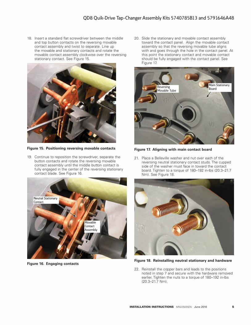
18. Insert a standard flat screwdriver between the middle and top button contacts on the reversing movable contact assembly and twist to separate. Line up the movable and stationary contacts and rotate the movable contact assembly clockwise over the reversing stationary contact. See Figure 15.
Figure 15. Positioning reversing movable contacts
19. Continue to reposition the screwdriver, separate the button contacts and rotate the reversing movable contact assembly until the middle button contact is fully engaged in the center of the reversing stationary contact blade. See Figure 16.
Neutral StationaryContact
MovableContactAssembly
Figure 16. Engaging contacts
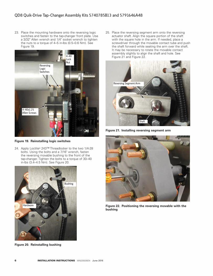
20. Slide the stationary and movable contact assembly toward the contact panel. Align the movable contact assembly so that the reversing movable tube aligns with and goes through the hole in the contact panel. At this point the stationary contact and movable contact should be fully engaged with the contact panel. See Figure 17.
Main StationaryBoard
ReversingMovable Tube
Figure 17. Aligning with main contact board
21. Place a Belleville washer and nut over each of the reversing neutral stationary contact studs. The cupped side of the washer must face in toward the contact board. Tighten to a torque of 180–192 in-lbs (20.3–21.7 Nm). See Figure 18.
Figure 18. Reinstalling neutral stationary and hardware
22. Reinstall the copper bars and leads to the positions noted in step 7 and secure with the hardware removed earlier. Tighten the nuts to a torque of 180–192 in-lbs (20.3–21.7 Nm).
6
QD8 Quik-Drive Tap-Changer Assembly Kits 5740785B13 and 5791646A48
INSTALLATION INSTRUCTIONS MN225035EN June 2016
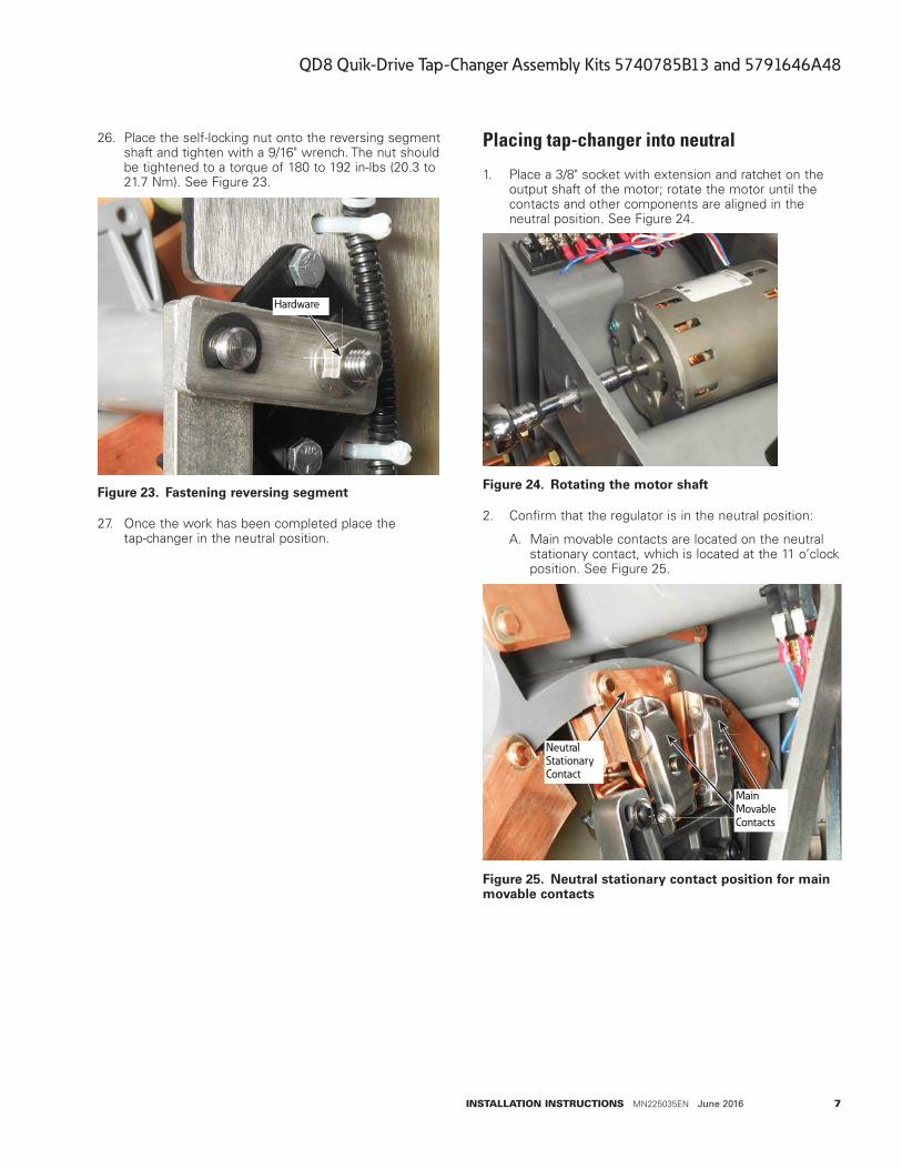
23. Place the mounting hardware onto the reversing logic switches and fasten to the tap-changer front plate. Use a 3/32" Allen wrench and 1/4" socket wrench to tighten the nuts to a torque of 4–5 in-lbs (0.5–0.6 Nm). See Figure 19.
ReversingLogicSwitches
4-40x1.25Allen Screws
4-40LockNut
Figure 19. Reinstalling logic switches
24. Apply Loctite® 243™ Threadlocker to the two 1/4-28 bolts. Using the bolts and a 7/16" wrench, fasten the reversing movable bushing to the front of the tap-changer. Tighten the bolts to a torque of 30–40 in-lbs (3.4–4.5 Nm). See Figure 20.
Hardware
Bushing
Figure 20. Reinstalling bushing
25. Place the reversing segment arm onto the reversing actuator shaft. Align the square portion of the shaft with the square hole in the arm. If needed, place a screwdriver through the movable contact tube and push the shaft forward while seating the arm over the shaft. It may be necessary to rotate the movable contact assembly slightly to align the shaft and hole. See Figure 21 and Figure 22.
Reversing Segment Arm
Shaft
Figure 21. Installing reversing segment arm
Figure 22. Positioning the reversing movable with the bushing
7
QD8 Quik-Drive Tap-Changer Assembly Kits 5740785B13 and 5791646A48
INSTALLATION INSTRUCTIONS MN225035EN June 2016
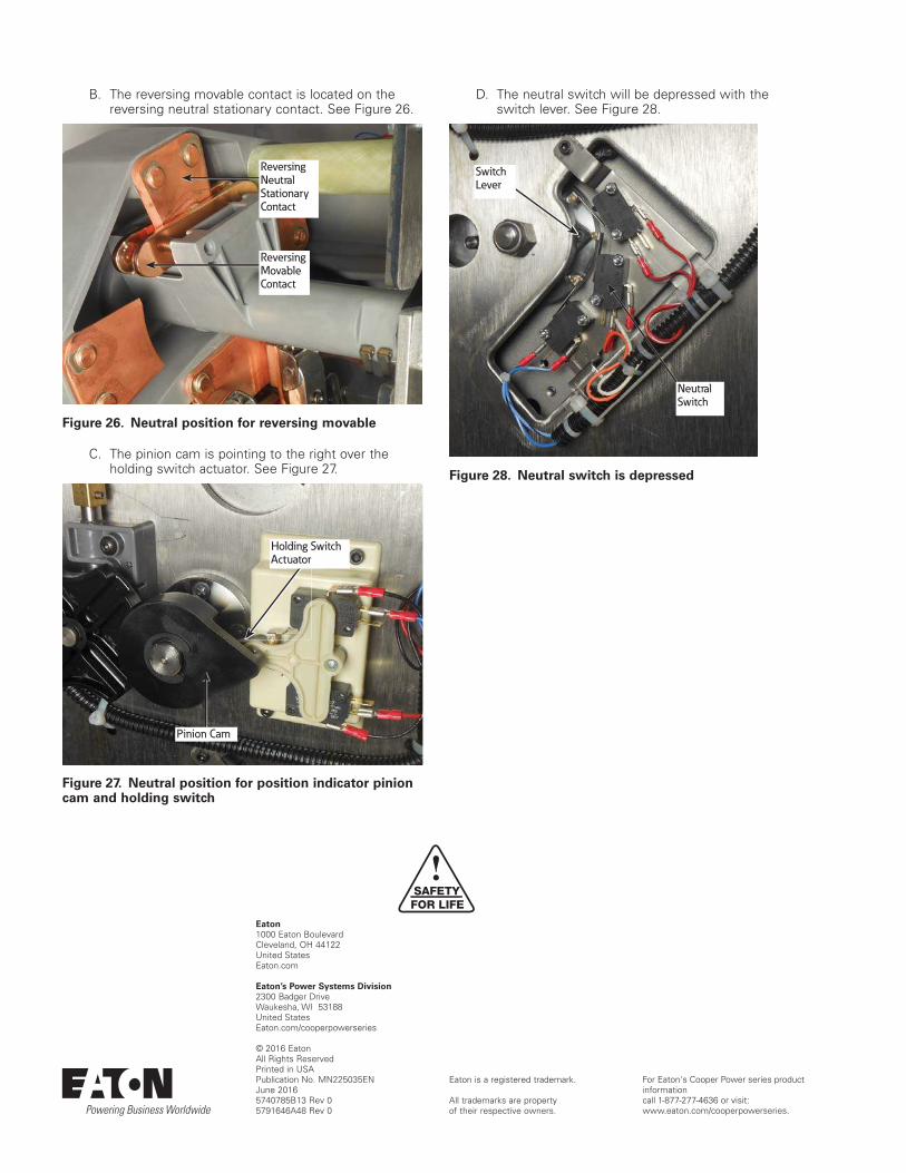
26. Place the self-locking nut onto the reversing segment shaft and tighten with a 9/16" wrench. The nut should be tightened to a torque of 180 to 192 in-lbs (20.3 to 21.7 Nm). See Figure 23.
Hardware
Figure 23. Fastening reversing segment
27. Once the work has been completed place the tap-changer in the neutral position.
Placing tap-changer into neutral
1. Place a 3/8" socket with extension and ratchet on the output shaft of the motor; rotate the motor until the contacts and other components are aligned in the neutral position. See Figure 24.
Figure 24. Rotating the motor shaft
2. Confirm that the regulator is in the neutral position:
A. Main movable contacts are located on the neutral stationary contact, which is located at the 11 o’clock position. See Figure 25.
MainMovableContacts
NeutralStationaryContact
Figure 25. Neutral stationary contact position for main movable contacts
Eaton1000 Eaton BoulevardCleveland, OH 44122United StatesEaton.com
Eaton’s Power Systems Division2300 Badger DriveWaukesha, WI 53188United StatesEaton.com/cooperpowerseries
© 2016 EatonAll Rights ReservedPrinted in USAPublication No. MN225035EN June 20165740785B13 Rev 0 5791646A48 Rev 0
Eaton is a registered trademark.
All trademarks are property of their respective owners.
For Eaton's Cooper Power series product information call 1-877-277-4636 or visit: www.eaton.com/cooperpowerseries.
!SAFETYFOR LIFE
B. The reversing movable contact is located on the reversing neutral stationary contact. See Figure 26.
ReversingNeutralStationaryContact
ReversingMovableContact
Figure 26. Neutral position for reversing movable
C. The pinion cam is pointing to the right over the holding switch actuator. See Figure 27.
Pinion Cam
Holding SwitchActuator
Figure 27. Neutral position for position indicator pinion cam and holding switch
D. The neutral switch will be depressed with the switch lever. See Figure 28.
NeutralSwitch
SwitchLever
Figure 28. Neutral switch is depressed