qnx neutrino realtime operating system · don’t: 260 b sample buildfiles 261 introduction 263...
TRANSCRIPT

QNX® Neutrino® Realtime
Operating SystemBuilding Embedded Systems
For targets running QNX® Neutrino® 6.3
© 2007, QNX Software Systems GmbH & Co. KG.

© 1996–2007, QNX Software Systems GmbH & Co. KG. All rights reserved.
Published under license by:
QNX Software Systems International Corporation175 Terence Matthews CrescentKanata, OntarioK2M 1W8CanadaVoice: +1 613 591-0931Fax: +1 613 591-3579Email: [email protected]: http://www.qnx.com/
Publishing history
December 1996 First edition
July 1997 Second edition
May 1999 Third edition
June 2004 Fourth edition
Electronic edition published 2007
QNX, Neutrino, Photon, Photon microGUI, Momentics, and Aviage are trademarks, registered in certain jurisdictions, of QNXSoftware Systems GmbH & Co. KG. and are used under license by QNX Software Systems International Corporation. All othertrademarks belong to their respective owners.
Contents
About This Book xvWhat you’ll find in this guide xvii
Typographical conventions xviii
Note to Windows users xix
Technical support xx
Overview of Building Embedded1Systems 1
Introduction 3
The role of the IPL 3
The role of the startup program 5
Startup’s responsibilities 6
The role of Neutrino 9
Hardware aspects 10
Choice of processor 10
Source of initialization and configuration 10
Choice of filesystems 11
I/O devices 15
Getting started 16
Hardware design 17
Customizing the software 17
Working with a BSP 212Proprietary and simplified packaging for BSPs 23
Installing proprietary BSP source code 24
September 10, 2007 Contents iii

© 2007, QNX Software Systems GmbH & Co. KG.
Structure of a BSP 25
docs subdirectory (simplified BSPs only) 26
images subdirectory 27
prebuilt subdirectory 27
install subdirectory 28
src subdirectory 29
Building a BSP OS image from source 29
Building source from the command line 30
Building source within the IDE 32
Building a BSP OS image from the binary components 33
Building an image from the command line (simplified BSPs)33
Building an image from the command line (proprietary BSPs)33
Building an image in the IDE 34
Creating a working set 34
Supporting additional devices 35
Transferring an OS image onto your board 36
Transferring an OS image 36
Working with a flash filesystem 37
Testing Neutrino on your board 41
Getting Photon on your board 41
Where do I go from here? 42
Filename conventions 43
Making an OS Image 453Images, images, images 47
What is an OS image? 47
The OS image as a filesystem 48
Configuring an OS image 49
A simple buildfile 49
Plain ordinary lists of files 52
Bound multiprocessing attributes 58
iv Contents September 10, 2007

© 2007, QNX Software Systems GmbH & Co. KG.
The bootstrap file 58
Specifying command-line options to mkifs 60
Listing the contents of an image 60
Building a flash filesystem image 61
Using mkefs 61
Compressing files 64
Compression rules 67
Design considerations 69
Embedding an image 70
Combining image files using mkimage 71
Converting images using mkrec 72
Transferring an image to flash 73
System configuration 75
Establishing an output device 76
Running drivers/filesystems 77
Running applications 81
Debugging an embedded system 82
pdebug software debugging agent 82
Hardware debuggers and Neutrino 83
Producing debug symbol information for IPL and startup 83
Writing an IPL Program 894Initial program loader (IPL) 91
Responsibilities of the IPL 91
Booting from a bank-switched device 93
Booting from a linear device 96
“Warm” vs “cold” start 96
Loading the image 97
Transferring control to the startup program 103
Customizing IPLs 103
Initialize hardware 104
Loading the image into RAM 104
Structure of the boot header 105
September 10, 2007 Contents v
© 2007, QNX Software Systems GmbH & Co. KG.
Relationship of struct startup_header fields 112
IPL structure 116
Creating a new IPL 120
The IPL library 120
Customizing Image Startup Programs 1315Introduction 133
Initialize hardware 133
Initialize system page 133
Initialize callouts 134
Anatomy of a startup program 134
Structure of a startup program 135
Creating a new startup program 136
Structure of the system page 137
size 138
total_size 138
type 138
num_cpu 139
system_private 139
asinfo 139
hwinfo 142
cpuinfo 150
syspage_entry cacheattr 154
syspage_entry qtime 158
callout 161
callin 161
typed_strings 162
strings 162
intrinfo 162
syspage_entry union un 169
un.x86 170
un.x86.smpinfo (deprecated) 170
un.ppc (deprecated) 171
vi Contents September 10, 2007

© 2007, QNX Software Systems GmbH & Co. KG.
un.ppc.kerinfo 171
un.mips 172
un.arm 172
un.sh 173
smp 173
pminfo 173
Callout information 174
Debug interface 175
Clock/timer interface 175
Interrupt controller interface 176
Cache controller interface 177
System reset callout 177
Power management callout 178
The startup library 178
add_cache() 178
add_callout() 178
add_callout_array() 179
add_interrupt() 179
add_interrupt_array() 179
add_ram() 179
add_string() 179
add_typed_string() 179
alloc_qtime() 180
alloc_ram() 180
as_add() 180
as_add_containing() 180
as_default() 181
as_find() 181
as_find_containing() 181
as_info2off() 182
as_off2info() 182
as_set_checker() 182
September 10, 2007 Contents vii

© 2007, QNX Software Systems GmbH & Co. KG.
as_set_priority() 182
avoid_ram() 182
calc_time_t() 183
calloc_ram() 183
callout_io_map_indirect() 183
callout_memory_map_indirect() 183
callout_register_data() 183
chip_access() 184
chip_done() 184
chip_read8() 185
chip_read16() 185
chip_read32() 185
chip_write8() 185
chip_write16() 185
chip_write32() 185
copy_memory() 185
del_typed_string() 186
falcon_init_l2_cache() 186
falcon_init_raminfo() 186
falcon_system_clock() 186
find_startup_info() 186
find_typed_string() 187
handle_common_option() 187
hwi_add_device() 188
hwi_add_inputclk() 188
hwi_add_irq() 188
hwi_add_location() 189
hwi_add_nicaddr() 189
hwi_add_rtc() 189
hwi_alloc_item() 189
hwi_alloc_tag() 190
hwi_find_as() 190
viii Contents September 10, 2007

© 2007, QNX Software Systems GmbH & Co. KG.
hwi_find_item() 190
hwi_find_tag() 191
hwi_off2tag() 191
hwi_tag2off() 191
init_asinfo() 192
init_cacheattr() 192
init_cpuinfo() 192
init_hwinfo() 192
init_intrinfo() 192
init_mmu() 193
init_pminfo() 193
init_qtime() 194
init_qtime_sa1100() 194
init_raminfo() 194
init_smp() 195
init_syspage_memory() (deprecated) 195
init_system_private() 195
jtag_reserve_memory() 195
kprintf() 196
mips41xx_set_clock_freqs() 196
openbios_init_raminfo() 196
pcnet_reset() 196
ppc400_pit_init_qtime() 196
ppc405_set_clock_freqs() 197
ppc600_set_clock_freqs() 197
ppc700_init_l2_cache() 197
ppc800_pit_init_qtime() 197
ppc800_set_clock_freqs() 198
ppc_dec_init_qtime() 198
print_syspage() 198
rtc_time() 199
startup_io_map() 201
September 10, 2007 Contents ix

© 2007, QNX Software Systems GmbH & Co. KG.
startup_io_unmap() 201
startup_memory_map() 202
startup_memory_unmap() 202
tulip_reset() 202
uncompress() 202
x86_cpuid_string() 203
x86_cputype() 203
x86_enable_a20() 203
x86_fputype() 204
x86_init_pcbios() 204
x86_pcbios_shadow_rom() 204
x86_scanmem() 204
Writing your own kernel callout 205
Find out who’s gone before 206
Why are they in assembly language? 207
Starting off 207
“Patching” the callout code 209
Getting some R/W storage 210
The exception that proves the rule 212
PPC chips support 212
Adding a new CPU to the startup library 217
Customizing the Flash Filesystem 2196Introduction 221
Driver structure 222
resmgr and iofunc layers 223
Flash filesystem component 223
Socket services component 223
Flash services component 224
Probe routine component 224
Building your flash filesystem driver 224
The source tree 224
The Makefile 227
x Contents September 10, 2007
© 2007, QNX Software Systems GmbH & Co. KG.
Making the driver 227
The main() function 227
Socket services interface 229
Options parsing 233
Flash services interface 234
Choosing the right routines 243
Example: The devf-ram driver 244
main() 244
f3s_ram_open() 245
f3s_ram_page() 247
System Design Considerations 249AIntroduction 251
Before you design your system 251
Other design considerations 253
NMI 258
Design do’s and don’ts 259
Do: 259
Don’t: 260
Sample Buildfiles 261BIntroduction 263
Generic examples 263
Shared libraries 263
Running executables more than once 264
Multiple consoles 265
Complete example — minimal configuration 266
Complete example — flash filesystem 267
Complete example — disk filesystem 269
Complete example — TCP/IP with network filesystem 271
Processor-specific notes 273
Specifying the processor 273
Specifying the startup program 274
September 10, 2007 Contents xi

© 2007, QNX Software Systems GmbH & Co. KG.
Specifying the serial device 274
Packaging a Board Support Package 275CStructure of a BSP 277
Packaging a BSP 278
Documentation, including installation and release notes 279
Eclipse plugins 279
Photon helpviewer files 282
Testing your BSP 284
Glossary 285
Index 309
xii Contents September 10, 2007

List of Figures
An OS image loaded by the IPL. 4
You may select as many storage options as you need. 12
The three main branches of the Neutrino source tree. 17
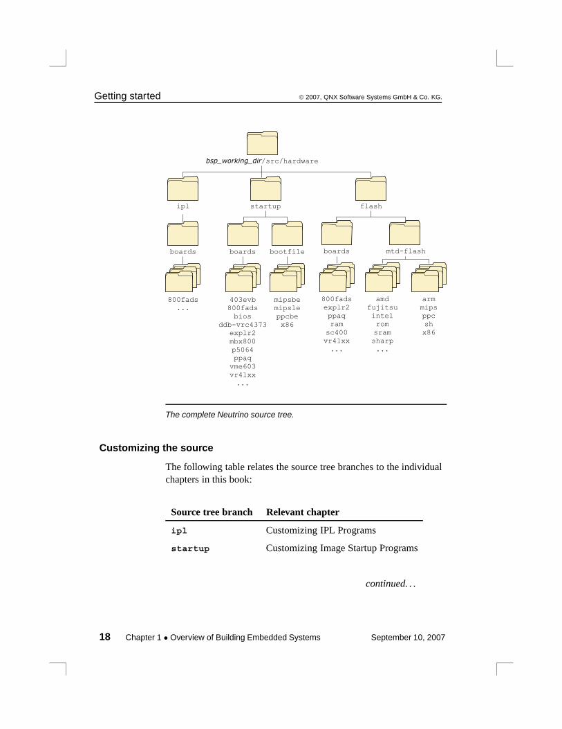
The complete Neutrino source tree. 18
BSP directory structure. 26
A sample prebuilt directory. 28
Flash configuration options for your Neutrino-based embeddedsystems. 70
Linearly mapped device. 99
Bank-switched devices. 100
Large storage medium, bank-switched into a window. 101
IPL directory structure. 117
Startup directory structure. 135
Two-processor system with separate L1 instruction and datacaches. 157
Structure of the flash filesystem driver. 222
Flash directory structure. 225
Directory structure of a BSP. 277
September 10, 2007 List of Figures xiii


About This Book
September 10, 2007 About This Book xv

© 2007, QNX Software Systems GmbH & Co. KG. What you’ll find in this guide
What you’ll find in this guideThe Building Embedded Systems guide is intended for developerswho are building embedded systems that will run under the QNXNeutrino RTOS.
QNX Neutrino runs on several processor families (e.g. PowerPC,MIPS, ARM, SH-4, x86). For information on getting started withNeutrino on a particular board, refer to the appropriate BSP (BoardSupport Package) documentation for your board.
This guide is organized around these main topics:
Topic Chapter(s)
Getting the big picture Overview of BuildingEmbedded Systems
Getting started with your boardsupport package
Working with a BSP
Making an image Making an OS Image
Preparing your target Writing an IPL Program;Customizing Image StartupPrograms;Customizing the FlashFilesystem;Sample Buildfiles
Dealing with hardware issues System Design Considerations
How to package a BSP thatyou’ve developed
Packaging a Board SupportPackage
Terms used in QNX docs Glossary
September 10, 2007 About This Book xvii

Typographical conventions © 2007, QNX Software Systems GmbH & Co. KG.
We assume that you’ve already installed QNX Neutrino and thatyou’re familiar with its architecture. For a detailed overview, see theSystem Architecture manual.
If you plan to use the Photon microGUI in your embedded system,refer to the “Photon in Embedded Systems” appendix in the PhotonProgrammer’s Guide.
Typographical conventionsThroughout this manual, we use certain typographical conventions todistinguish technical terms. In general, the conventions we useconform to those found in IEEE POSIX publications. The followingtable summarizes our conventions:
Reference Example
Code examples if( stream == NULL )
Command options -lR
Commands make
Environment variables PATH
File and pathnames /dev/null
Function names exit()
Keyboard chords Ctrl-Alt-Delete
Keyboard input something you type
Keyboard keys Enter
Program output login:
Programming constants NULL
Programming data types unsigned short
continued. . .
xviii About This Book September 10, 2007
© 2007, QNX Software Systems GmbH & Co. KG. Typographical conventions
Reference Example
Programming literals 0xFF, "message string"
Variable names stdin
User-interface components Cancel
We use an arrow (→) in directions for accessing menu items, like this:
You’ll find the Other... menu item underPerspective→Show View.
We use notes, cautions, and warnings to highlight importantmessages:
Notes point out something important or useful.
CAUTION: Cautions tell you about commands or procedures thatmay have unwanted or undesirable side effects.!
WARNING: Warnings tell you about commands or proceduresthat could be dangerous to your files, your hardware, or evenyourself.
Note to Windows usersIn our documentation, we use a forward slash (/) as a delimiter in allpathnames, including those pointing to Windows files.
We also generally follow POSIX/UNIX filesystem conventions.
September 10, 2007 About This Book xix

Technical support © 2007, QNX Software Systems GmbH & Co. KG.
Technical supportTo obtain technical support for any QNX product, visit the Support +Services area on our website (www.qnx.com). You’ll find a widerange of support options, including community forums.
xx About This Book September 10, 2007
Chapter 1
Overview of Building EmbeddedSystems
In this chapter. . .Introduction 3Hardware aspects 10Getting started 16
September 10, 2007 Chapter 1 • Overview of Building Embedded Systems 1

© 2007, QNX Software Systems GmbH & Co. KG. Introduction
IntroductionIn this chapter, we’ll take a “high-level” look at the steps necessary tobuild a complete Neutrino-based embedded system, with pointers tothe appropriate chapters for the lower-level details.
First we’ll see what a Neutrino system needs to do in order to run.Then we’ll look at the components and how they operate. Finally,we’ll do an overview of the steps you may need to follow whencustomizing certain portions.
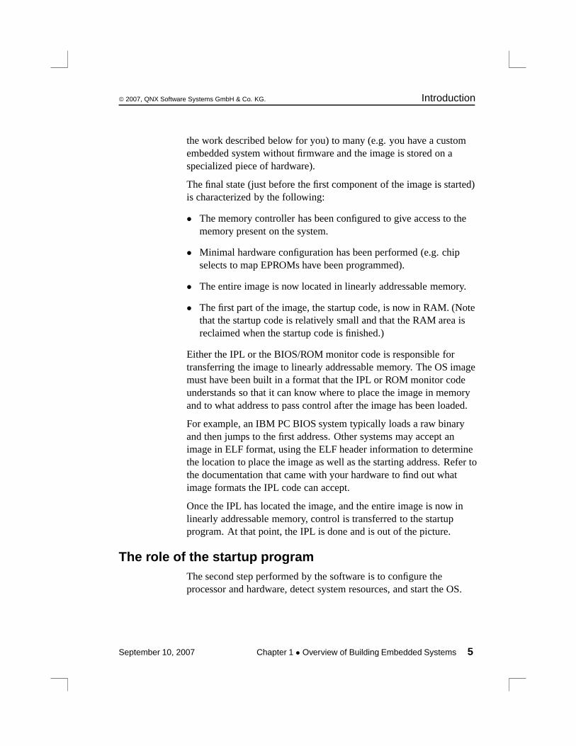
From the software perspective, the following steps occur when thesystem starts up:
1 Processor begins executing at the reset vector. The InitialProgram Loader (IPL) locates the OS image and transferscontrol to the startup program in the image.
2 Startup program configures the system and transfers control tothe Neutrino microkernel and process manager (procnto).
3 The procnto module loads additional drivers and applicationprograms.
After we look at the software aspects in some more detail, we’llconsider the impact that the hardware has on this startup process.
The role of the IPLThe first step performed by the software is to load the OS image. Thisis done by a program called the Initial Program Loader (IPL).
The IPL’s initial task is to minimally configure the hardware to createan environment that will allow the startup program, and consequentlythe Neutrino microkernel, to run. Specifically, this task includes atleast the following steps:
1 Start execution from the reset vector.
2 Configure the memory controller, which may includeconfiguring chip selects and/or PCI controller.
September 10, 2007 Chapter 1 • Overview of Building Embedded Systems 3
Introduction © 2007, QNX Software Systems GmbH & Co. KG.
3 Configure clocks.
4 Set up a stack to allow the IPL lib to perform OS verificationand setup (image download, scan, setup, and jump).
The IPL is described in detail in the chapter on Writing an IPLProgram.
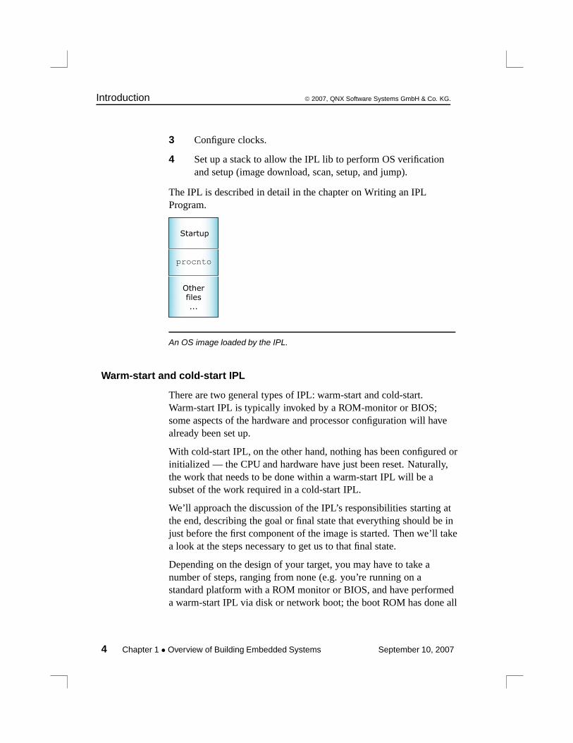
Otherfiles...
procnto
Startup
An OS image loaded by the IPL.
Warm-start and cold-start IPL
There are two general types of IPL: warm-start and cold-start.Warm-start IPL is typically invoked by a ROM-monitor or BIOS;some aspects of the hardware and processor configuration will havealready been set up.
With cold-start IPL, on the other hand, nothing has been configured orinitialized — the CPU and hardware have just been reset. Naturally,the work that needs to be done within a warm-start IPL will be asubset of the work required in a cold-start IPL.
We’ll approach the discussion of the IPL’s responsibilities starting atthe end, describing the goal or final state that everything should be injust before the first component of the image is started. Then we’ll takea look at the steps necessary to get us to that final state.
Depending on the design of your target, you may have to take anumber of steps, ranging from none (e.g. you’re running on astandard platform with a ROM monitor or BIOS, and have performeda warm-start IPL via disk or network boot; the boot ROM has done all
4 Chapter 1 • Overview of Building Embedded Systems September 10, 2007
© 2007, QNX Software Systems GmbH & Co. KG. Introduction
the work described below for you) to many (e.g. you have a customembedded system without firmware and the image is stored on aspecialized piece of hardware).
The final state (just before the first component of the image is started)is characterized by the following:
• The memory controller has been configured to give access to thememory present on the system.
• Minimal hardware configuration has been performed (e.g. chipselects to map EPROMs have been programmed).
• The entire image is now located in linearly addressable memory.
• The first part of the image, the startup code, is now in RAM. (Notethat the startup code is relatively small and that the RAM area isreclaimed when the startup code is finished.)
Either the IPL or the BIOS/ROM monitor code is responsible fortransferring the image to linearly addressable memory. The OS imagemust have been built in a format that the IPL or ROM monitor codeunderstands so that it can know where to place the image in memoryand to what address to pass control after the image has been loaded.
For example, an IBM PC BIOS system typically loads a raw binaryand then jumps to the first address. Other systems may accept animage in ELF format, using the ELF header information to determinethe location to place the image as well as the starting address. Refer tothe documentation that came with your hardware to find out whatimage formats the IPL code can accept.
Once the IPL has located the image, and the entire image is now inlinearly addressable memory, control is transferred to the startupprogram. At that point, the IPL is done and is out of the picture.
The role of the startup programThe second step performed by the software is to configure theprocessor and hardware, detect system resources, and start the OS.
September 10, 2007 Chapter 1 • Overview of Building Embedded Systems 5
Introduction © 2007, QNX Software Systems GmbH & Co. KG.
This is done by the startup program. (For details, see the chapter onCustomizing Image Startup Programs.)
While the IPL did the bare minimum configuration necessary to getthe system to a state where the startup program can run, the startupprogram’s job is to “finish up” the configuration. If the IPL detectedvarious resources, it would communicate this information to thestartup program (so it wouldn’t have to redetect the same resources.)
To keep Neutrino as configurable as possible, we’ve given the startupprogram the ability to program such things as the base timers,interrupt controllers, cache controllers, and so on. It can also providekernel callouts, which are code fragments that the kernel can call toperform hardware-specific functions. For example, when a hardwareinterrupt is triggered, some piece of code must determine the sourceof the interrupt, while another piece of code must be able to clear thesource of the interrupt.
Note that the startup program does not configure such things as thebaud rate of serial ports. Nor does it initialize standard peripheraldevices like an Ethernet controller or EIDE hard disk controller —these are left for the drivers to do themselves when they start up later.
Once the startup code has initialized the system and has placed theinformation about the system in the system page area (a dedicatedpiece of memory that the kernel will look at later), the startup code isresponsible for transferring control to the Neutrino kernel and processmanager (procnto), which perform the final loading step.
Startup’s responsibilitiesLet’s take a look at the overall responsibilities and flow of the startupcode:
1 Copy and decompress the image, if necessary.
2 Configure hardware.
3 Determine system configuration.
4 Start the kernel.
6 Chapter 1 • Overview of Building Embedded Systems September 10, 2007
© 2007, QNX Software Systems GmbH & Co. KG. Introduction
Copying and decompressing the image
If the image isn’t in its final destination in RAM, the startup codecopies it there. If the image is compressed, the startup codeautomatically decompresses the image. Compression is optional; youcan create an image file that isn’t compressed, in which case thestartup code won’t bother trying to decompress it.
Configuring the hardware
The main task here is to set up the minimum required to be able todetermine the system configuration (and then perform the systemconfiguration).
The details of what needs to be configured during the hardwareconfiguration phase depend on your particular hardware.
Determining system configuration
Depending on the nature of the embedded system, you may wish todynamically determine the configuration on startup or (in the case of adeeply embedded system) simply “hardcode” the configurationinformation.
Regardless of the source of the information, the configuration part ofthe startup code needs to store this information into a set ofwell-defined data structures that the OS will then look at when itstarts. Collectively known as the system page area, these datastructures contain information about:
• memory configuration
• hardware device configuration
• processor type
• time of day
September 10, 2007 Chapter 1 • Overview of Building Embedded Systems 7

Introduction © 2007, QNX Software Systems GmbH & Co. KG.
Establishing callouts
To keep the Neutrino kernel as portable as possible (not only todifferent processors, but also to different hardware configurations ofthose processors), a number of callouts must be supplied by thestartup code. Not all of the callouts require that you write code — wehave a library that provides many of these.
The following classes of callout functions can be provided forNeutrino:
• debug interface
• clock/timer interface
• interrupt controller interface
• cache controller interface
• power management
• miscellaneous
The callouts are described in detail in the chapter on CustomizingImage Startup Programs.
Starting the OS
The final step that the startup code performs is to start the operatingsystem.
The startup library
If all of the above sounds like a lot of work, well, it is! Note, however,that we’ve provided source code for some common startup programsand have created a library that performs most of the above functionsfor you.
If you have one of the many platforms that we support, then you don’thave to do any of this work — we’ve already done it for you.
To find out what processors and boards we currently support, pleaserefer to the following sources:
8 Chapter 1 • Overview of Building Embedded Systems September 10, 2007
© 2007, QNX Software Systems GmbH & Co. KG. Introduction
• the boards directory underbsp_working_dir/src/hardware/startup/boards.
• QNX docs (BSP docs as well as startup-* entries in the UtilitiesReference).
If you have a nonstandard embedded system, you can look at thesource for the system that most closely resembles yours and “clone”the appropriate functionality from the examples provided.
This issue is discussed in detail in the chapter on Customizing ImageStartup Programs.
The role of NeutrinoThe third step performed by the software is to start any executablesthat you want to be running. The OS does this by reading andprocessing information stored in the startup script — a sequence ofcommands stored within the image. The format of the startup script,as well as the buildfile that it’s part of, is documented in detail in avariety of places in this guide:
• Making an OS Image chapter — describes the steps required tobuild a Neutrino-based system, including discussions of the scriptfile and buildfile.
• Sample Buildfiles appendix in this guide — describes common“tricks” used within the buildfile and also contains completeexamples of sample configurations.
• mkifs doc — describes the mkifs utility, which is used to createthe image from the description passed to it in the buildfile. See theUtilities Reference for details.
• Building OS and Flash Images chapter in the IDE User’s Guide —describes the how the OS and Flash images are created in the IDE.
Basically, the OS processes the startup script file, which looks like ashell script. In the startup script file, you’d specify which executablesshould be started up (and their order), the command-line options thatthey should run with, and so on.
September 10, 2007 Chapter 1 • Overview of Building Embedded Systems 9
Hardware aspects © 2007, QNX Software Systems GmbH & Co. KG.
Hardware aspectsFrom the hardware point of view, the following components form thesystem:
• processor
• source of initialization and configuration info
• storage media
• I/O devices
Choice of processorWe support the following processor families:
• ARM (including XScale)
• MIPS
• PowerPC
• SH-4
• x86
At the “altitude” of this high-level discussion, the choice of processoris irrelevant — the same basic steps need to be performed regardlessof the particular CPU.
Source of initialization and configurationWhen the processor (re)starts, it must be able to execute instructions.This is accomplished by having some kind of nonvolatile storagemedia placed at the processor’s reset vector. There is, of course, achoice as to who supplies this particular piece of software:
• QNX Software Systems — you’ve chosen a standard, supportedhardware platform;
• 3rd party — a BIOS or ROM monitor; or
10 Chapter 1 • Overview of Building Embedded Systems September 10, 2007
© 2007, QNX Software Systems GmbH & Co. KG. Hardware aspects
• you — a custom IPL program.
Generally, the simplest development system is one in which you haveto do the least amount of work. If we’ve already done the work,meaning that the board that you’re using is a standard, supportedhardware platform, there’s very little work required from you in thisregard; you can instead focus on your software that’s going to run onthat board.
If a 3rd party supplies just the BIOS or ROM monitor, then yourresponsibilities are increased by having to write the software thatstarts the operating system. As mentioned earlier, we call this a“warm-start,” because the system is already “warmed-up” — variousdevices are configured and initialized.
If you’re supplying a custom IPL, then your responsibilities arefurther increased by also having to deal with configuration issues forthe hardware. This we call a “cold-start,” because you are responsiblefor everything to do with initialization and configuration.
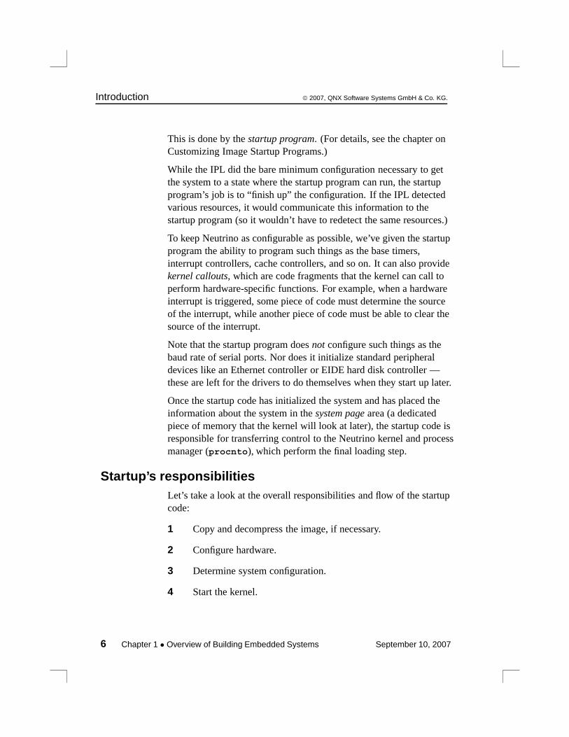
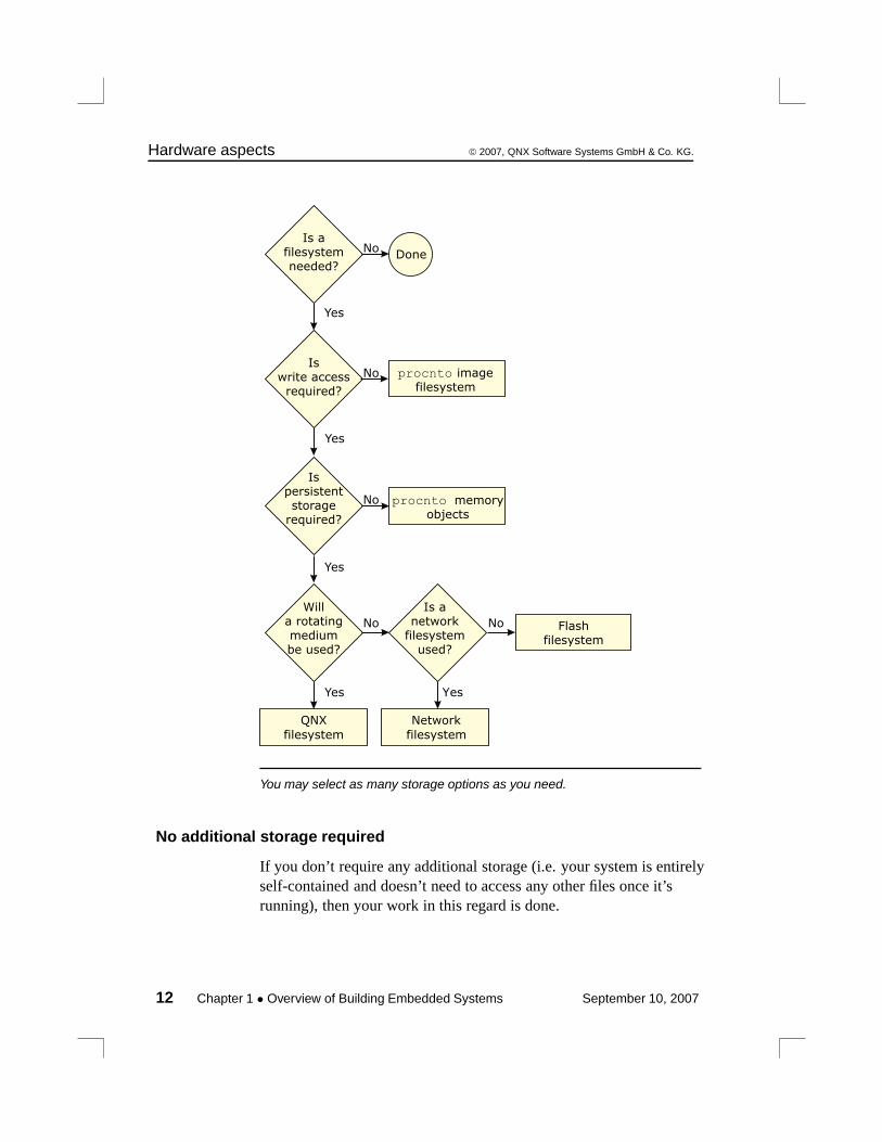
Choice of filesystemsOnce you’ve sorted out how the system is going to boot, you may stillhave additional decisions to make regarding the system’s storagecapabilities:
• none
• read-only
• read/write nonpersistent
• read/write persistent
September 10, 2007 Chapter 1 • Overview of Building Embedded Systems 11
Hardware aspects © 2007, QNX Software Systems GmbH & Co. KG.
No
No
Yes
Yes
Yes
No
Yes
Flashfilesystem
QNX
filesystem
No
Yes
Network
filesystem
Done
No
Is afilesystemneeded?
Iswrite accessrequired?
Ispersistentstorage
required?
Willa rotatingmediumbe used?
Is anetwork
filesystemused?
procnto memoryobjects
procnto imagefilesystem
You may select as many storage options as you need.
No additional storage required
If you don’t require any additional storage (i.e. your system is entirelyself-contained and doesn’t need to access any other files once it’srunning), then your work in this regard is done.
12 Chapter 1 • Overview of Building Embedded Systems September 10, 2007
© 2007, QNX Software Systems GmbH & Co. KG. Hardware aspects
Additional read-only storage required
The simplest filesystem scenario is one where read-only access isrequired. There’s no work for you to do — Neutrino provides thisfunctionality as part of the OS itself. Simply place the files that youwish to access/execute directly into the image (see the chapter onMaking an OS Image), and the OS will be able to access them.
Additional read/write nonpersistent storage required
If you require write access (perhaps for temporary files, logs, etc.),and the storage doesn’t have to be persistent in nature (meaning that itdoesn’t need to survive a reset), then once again the work is done foryou.
Neutrino allows the RAM in your system to be used as a RAM-disk,without any additional coding or device drivers. The RAM-disk isimplemented via the Process Manager — you simply set up a ProcessManager link (using the ln command).
For example, to mount the /tmp directory as a RAM-disk, execute thefollowing command:
ln -Ps /dev/shmem /tmp
Or place the following line in your buildfile (we’ll talk aboutbuildfiles over the next few chapters):
[type=link] /tmp=/dev/shmem
This instructs the Process Manager to take requests for any files under/tmp and resolve them to the shared memory subsystem. Forexample, /tmp/AAA4533.tmp becomes a request for/dev/shmem/AAA4533.tmp.
September 10, 2007 Chapter 1 • Overview of Building Embedded Systems 13
Hardware aspects © 2007, QNX Software Systems GmbH & Co. KG.
In order to minimize the size of the RAM filesystem code inside theProcess Manager, the shared memory filesystem specifically doesn’tinclude “big filesystem” features such as file locking and directorycreation.
If you need a relatively full-featured, POSIX-style filesystem on aRAM disk, use devf-ram or the builtin RAM disk via io-blkinstead.
Additional read/write persistent storage required
If you do require storage that must survive a power failure orprocessor reset, then you’ll need to run an additional driver. Wesupply these classes of filesystems:
• flash filesystems
• rotating disk filesystems
• network filesystems
All of these filesystems require additional drivers. The SampleBuildfiles appendix in this guide gives detailed examples showinghow to set up these filesystem drivers.
Flash filesystems and media
The flash driver can interface to the flash memory devices (boot blockand regular) in all combinations of bus widths (8, 16, and 32 bits) andinterleave factors (1, 2, and 4).
To find out what flash devices we currently support, please refer to thefollowing sources:
• the boards and mtd-flash directories underbsp_working_dir/src/hardware/flash.
• QNX docs (devf-* entries in Utilities Reference).
• the QNX Software Systems web site (www.qnx.com).
14 Chapter 1 • Overview of Building Embedded Systems September 10, 2007
© 2007, QNX Software Systems GmbH & Co. KG. Hardware aspects
Using the source code provided, you may be able to tailor one of ourfilesystems (e.g. devf-generic) to operate on your particularembedded system (if it isn’t currently supported).
Rotating media and filesystems
Neutrino currently supports several filesystems, including DOS,Linux, QNX 4, CD-ROM, and more. For details, see the fs-* entriesin the Utilities Reference.
Drivers are available for many block-oriented devices. For up-to-dateinformation, see the devb-* entries in the Utilities Reference as wellas the Community area of our website, www.qnx.com.
Network media and filesystems
During development, or perhaps in a distributed data-gatheringapplication, you may wish to have a filesystem located on onemachine and to be able to access that filesystem from other machines.A network filesystem lets you do this.
In addition to its own transparent distributed processing system(Qnet), QNX Neutrino also supports network filesystems such asCIFS (SMB), NFS 2, and NFS 3.
Drivers are available for the several Ethernet controllers. For details,see the devn-* entries in the Utilities Reference as well as theCommunity area of our website, www.qnx.com.
I/O devicesUltimately, your Neutrino-based system will need to communicatewith the outside world. Here are some of the more common ways todo this:
• serial/parallel port
• network (described above)
• data acquisition/generation
• multimedia
September 10, 2007 Chapter 1 • Overview of Building Embedded Systems 15
Getting started © 2007, QNX Software Systems GmbH & Co. KG.
Character I/O devices
For standard serial ports, Neutrino supports several devices (8250family, Signetics, etc.) For details, see the devc-* entries in theUtilities Reference as well as the Community area of our website,www.qnx.com.
Special/custom devices
One design issue you face is whether you can get off-the-shelf driversfor the hardware or whether you’ll have to write your own. If it turnsout that you need to write your own, then the Writing a ResourceManager chapter in the Programmer’s Guide can help you do that.
Getting startedDepending on the ultimate system you’ll be creating, you may have aton of work to do or you may have very little. In any case, werecommend that you start with a supported evaluation board. Thisapproach minimizes the amount of low-level work that you have to doinitially, thereby allowing you to focus on your system rather than onimplementation details.
Start with an evaluation platform that most closely resembles yourtarget platform — there are many supported evaluation platformsfrom various vendors.
Once you’re comfortable with the development environment and havedone a very rudimentary “proof of concept,” you can move on to suchdevelopment efforts as creating your own hardware, writing your ownIPL and startup code, writing drivers for your hardware, and so on.
Your proof of concept should address such issues as:
• How much memory will be required?
• How fast a CPU will be required?
• Can standard off-the-shelf hardware do the job?
Once these are addressed, you can then decide on your plan of attack.
16 Chapter 1 • Overview of Building Embedded Systems September 10, 2007
© 2007, QNX Software Systems GmbH & Co. KG. Getting started
Hardware designThere are a number of ways of designing your hardware. We’ve seenmany boards come in from the field and have documented some ofour experiences with them in the System Design Considerationsappendix in this book. You may be able to realize certain savings (inboth cost and time) by reading that appendix first.
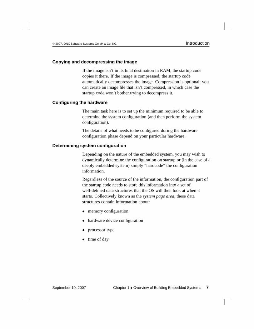
Customizing the softwareIdeally, the system you’re designing will look identical to a supportedevaluation platform. In reality, this isn’t always the case, so you’llneed to customize some of the components in that system.
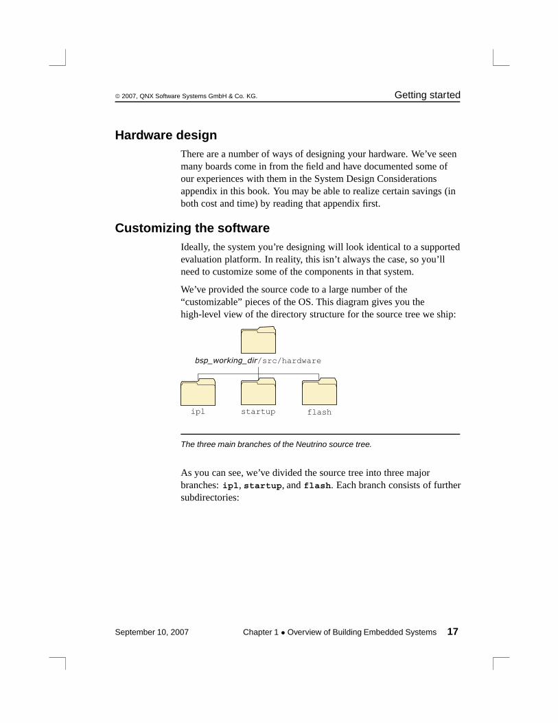
We’ve provided the source code to a large number of the“customizable” pieces of the OS. This diagram gives you thehigh-level view of the directory structure for the source tree we ship:
flashstartupipl
bsp_working_dir/src/hardware
The three main branches of the Neutrino source tree.
As you can see, we’ve divided the source tree into three majorbranches: ipl, startup, and flash. Each branch consists of furthersubdirectories:
September 10, 2007 Chapter 1 • Overview of Building Embedded Systems 17
Getting started © 2007, QNX Software Systems GmbH & Co. KG.
bsp_working_dir/src/hardware
startup
boards
403evb800fadsbios
ddb-vrc4373explr2mbx800p5064ppaq
vme603vr41xx...
bootfile
mipsbemipsleppcbex86
flash
boards
800fadsexplr2ppaqram
sc400vr41xx...
mipsppc
x86
mtd-flash
amdfujitsuintel
sharp
romsram
...
ipl
boards
800fads...
arm
sh
The complete Neutrino source tree.
Customizing the source
The following table relates the source tree branches to the individualchapters in this book:
Source tree branch Relevant chapter
ipl Customizing IPL Programs
startup Customizing Image Startup Programs
continued. . .
18 Chapter 1 • Overview of Building Embedded Systems September 10, 2007
© 2007, QNX Software Systems GmbH & Co. KG. Getting started
Source tree branch Relevant chapter
flash Customizing the Flash Filesystem
For detailed information on the format of the Makefile present inthese directories, please see Conventions for Makefiles andDirectories in the Programmer’s Guide.
September 10, 2007 Chapter 1 • Overview of Building Embedded Systems 19

Chapter 2
Working with a BSP
In this chapter. . .Proprietary and simplified packaging for BSPs 23Installing proprietary BSP source code 24Structure of a BSP 25Building a BSP OS image from source 29Building a BSP OS image from the binary components 33Supporting additional devices 35Transferring an OS image onto your board 36Testing Neutrino on your board 41Getting Photon on your board 41Where do I go from here? 42Filename conventions 43
September 10, 2007 Chapter 2 • Working with a BSP 21

© 2007, QNX Software Systems GmbH & Co. KG. Proprietary and simplified packaging for BSPs
Once you’ve installed the QNX Momentics development suite, youcan download processor-specific Board Support Packages (BSPs)from our website, http://www.qnx.com/. These BSPs aredesigned to help you get Neutrino running on certain platforms.
A BSP typically includes the following:
• IPL
• Startup
• default buildfile
• networking support
• suite of device drivers, system managers, utilities, etc.
The BSP is contained in an archive named after theindustry-recognized name of the board and/or reference platform thatthe BSP supports. BSP packages are available for QNX Neutrino,Windows, or Linux hosts.
You can build a BSP from the source code or the binary componentscontained in the BSP package.
Proprietary and simplified packaging forBSPsWe provide BSP packages in both proprietary and simplified styles.
Here’s how to determine which style a BSP is:
• Simplified BSPs are packaged as a zip file, and the same archiveapplies to all hosts. As described in the installation notes, you needto use the setupbsp command to install the BSP. ProprietaryBSPs are packaged as host-specific archives that use InstallShieldon Windows and Linux, or an installation script on Neutrino.
September 10, 2007 Chapter 2 • Working with a BSP 23
Installing proprietary BSP source code © 2007, QNX Software Systems GmbH & Co. KG.
The setupbsp script puts two copies of the BSP on your system, inthese locations:
- in a directory of your choosing, for use with the command-linetools
- under $QNX_TARGET, for importing into the IDE
Decide whether to use the command-line tools or the IDE, and don’twork with the other copy.
• Once installed, a simplified BSP optionally includes a docsdirectory.
• Proprietary BSPs install any binaries in the appropriate directoryunder $QNX_TARGET, potentially overwriting binaries placedthere by other BSPs.
• The source (if included) for a proprietary BSP is installed as a zipfile that you must expand before you build the BSP; any source fora simplified BSP is simply part of the installed directory structure.
• To build a proprietary BSP, you must run the setenv.sh script inthe root directory of the BSP before you run make; in a simplifiedBSP, we’ve incorporated setenv.sh right in the Makefiles.
The sections that follow point out any other differences between thestyles.
Installing proprietary BSP source codeWhen you install a proprietary BSP, the binaries are copied to theappropriate directory under $QNX_TARGET, potentiallyoverwriting binaries placed there by other BSPs.
The source code (if included) is a zip file that’s placed in$QNX_TARGET/usr/src/archives/qnx. To install the source fora proprietary BSP, you must manually expand its directory structurefrom this archive.
24 Chapter 2 • Working with a BSP September 10, 2007
© 2007, QNX Software Systems GmbH & Co. KG. Structure of a BSP
If you aren’t using the IDE and you want to manually install a BSParchive, we recommend that you create a default directory with thesame name as your BSP and unzip the archive from there:
1 Change the directory to where you want to extract the BSP (e.g./home/joe).
The archive will extract to the current directory, so you should createa directory specifically for your BSP.
For example:
mkdir /home/joe/bspname
2 In the directory you’ve just created, extract the BSP:
unzip $QNX_TARGET/usr/src/archives/qnx/bspname.zip
Each BSP is rooted in whatever directory you copy it to. If you typemake within this directory, you’ll generate all of the buildable entitieswithin that BSP no matter where you move the directory.
Proprietary BSPs include a setenv.sh script that you must run sothat typing make or make install doesn’t affect the host system. Ifyou use this script, all binaries are placed in an install area withinthe BSP directory that mimics the layout of a target system.
When you build a BSP, everything it needs, aside from standardsystem headers, is pulled in from within its own directory. Nothingthat’s built is installed outside of the BSP’s directory. The makefilesshipped with the BSPs copy the contents of the prebuilt directoryinto the install directory. The binaries are built from the sourceusing include files and link libraries in the install directory.
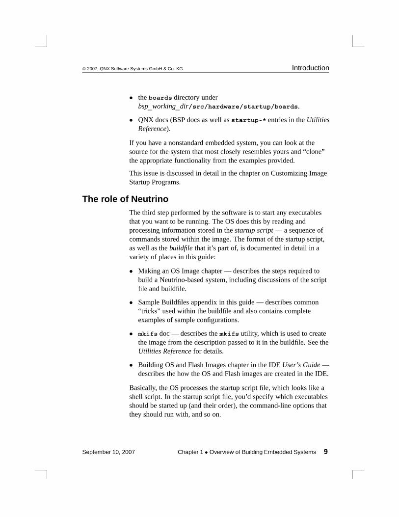
Structure of a BSPIf you install a simplified BSP, or a proprietary BSP that includessource code, the resulting directory structure looks like this:
September 10, 2007 Chapter 2 • Working with a BSP 25
Structure of a BSP © 2007, QNX Software Systems GmbH & Co. KG.
bsp_working_dir
images prebuiltinstall src
devcdevnflashipl
startup
hardware
docs
usr
help
product
bsp_name
usr
dll
lib
usr
includebin sbin
binlibsbin
targetusr
dll
libbin sbin
binlibsbin
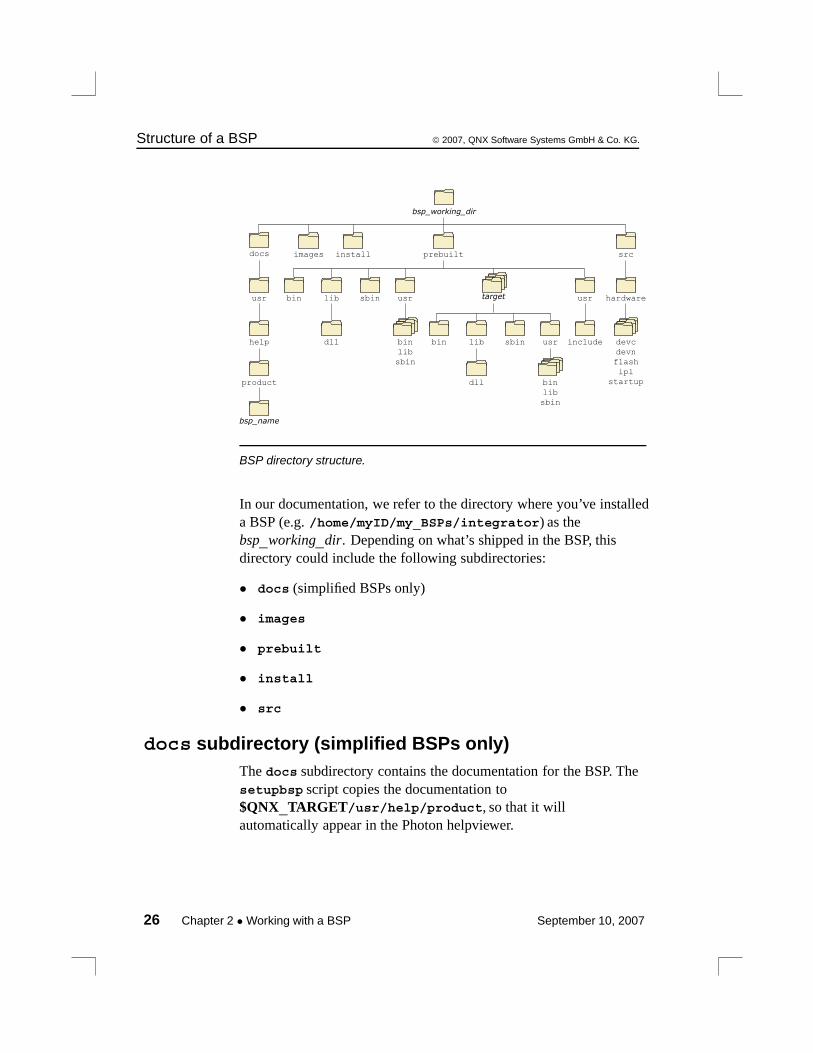
BSP directory structure.
In our documentation, we refer to the directory where you’ve installeda BSP (e.g. /home/myID/my_BSPs/integrator) as thebsp_working_dir. Depending on what’s shipped in the BSP, thisdirectory could include the following subdirectories:
• docs (simplified BSPs only)
• images
• prebuilt
• install
• src
docs subdirectory (simplified BSPs only)The docs subdirectory contains the documentation for the BSP. Thesetupbsp script copies the documentation to$QNX_TARGET/usr/help/product, so that it willautomatically appear in the Photon helpviewer.
26 Chapter 2 • Working with a BSP September 10, 2007

© 2007, QNX Software Systems GmbH & Co. KG. Structure of a BSP
images subdirectoryThe images subdirectory is where the resultant boot images areplaced. It contains (as a minimum) the Makefile needed to build theimage(s). Other files that could reside in this directory include:
• custom buildfiles (for flash, etc.)
• EFS buildfiles
• IPL build scripts
prebuilt subdirectoryThe prebuilt subdirectory contains the binaries, system binaries,buildfiles, libraries, and header files that are shipped with the BSP.
Before the BSP is built, all of the files from the prebuilt directoryare copied into the install directory, maintaining the path structure.
In order to handle dependencies, the libraries, headers, and other filesfound in the ./prebuilt directory need to be copied correctly toyour ./install directory. To do this, you’ll need to run make at thebsp_working_dir directory level.
The “root” of the prebuilt directory requires the same structure asthe system root. The target-specific and usr directories mirror thestructure of /.
All processor-specific binaries are located under the directory namedfor that processor type.
For example, the prebuilt directory might look like this:
September 10, 2007 Chapter 2 • Working with a BSP 27

Structure of a BSP © 2007, QNX Software Systems GmbH & Co. KG.
prebuilt
usr
includesbin
ppcbe
ppcdrvr sys
lib
libdrvrS.alibstartup.a
devb-eide
eth.hmdi.h
support.h
util.ah dcmd_io-net.hnic.h
platform.htypes.h
sys
boot
build
ipl-boardstartup-board
board.build
sbin
devc-ser*devc-tser*
pci-*
A sample prebuilt directory.
install subdirectoryThe install directory gets populated at the beginning of the BSPbuild process. All the files in the prebuilt directory are copied, thenall generated binaries are installed here as they’re compiled. The filesstored in the install directory are taken first when mkifs executes.
Before you make any components for your particular board, you mustfirst make the BSP sources at the top level:
cd bsp_working_dirmake
This builds everything under ./src and sets up the ./installdirectory correctly.
After this initial build is complete, you can build any of the sourcefiles individually.
28 Chapter 2 • Working with a BSP September 10, 2007
© 2007, QNX Software Systems GmbH & Co. KG. Building a BSP OS image from source
If you change a library or header, be sure to run make install torebuild the source and copy the changes to your ./installdirectory.
src subdirectoryIf the BSP includes source code, it’s stored in this directory. Thehardware directory contains separate directories for character, flash,and network drivers, IPL, startup code, and so on, depending on theBSP.
The src directory contains a buildfile,src/hardware/startup/boards/board/build, that overridesthe one in the prebuilt directory.
Building a BSP OS image from sourceIf you’re building the BSP OS image from source code on the host,you can:
• use the command line
• import the source code within the IDE
September 10, 2007 Chapter 2 • Working with a BSP 29
Building a BSP OS image from source © 2007, QNX Software Systems GmbH & Co. KG.
When you build a BSP from the source code, you may occasionallyobserve warnings from some of the tools used to generate the BSP,such as:
• objcopy: Warning: Output file cannot represent
architecture UNKNOWN!
• ntosh-ld: Warning: could not find any targets
that match endianness requirement
These warnings result when information that’s contained in oneparticular file format (endianness, CPU architecture, etc.) can’t beretained when converting that file to a different format, or when theoriginating file format doesn’t contain information that the tool doingthe conversion expects. These warnings are normal and expected, andare no cause for concern.
Building source from the command lineIn order to build a BSP from the command line, you must go to theroot directory for the BSP.
Building the source is similar for proprietary and simplified BSPs,except that for a proprietary BSP, you must run the setenv.sh scriptin the BSP’s root directory. This script configures your environmentto build the BSP. On Windows, you must run the Bash shell(bash.exe) before you run setenv.sh.
Run the setenv.sh script as a “dot” file, so that it configures yourcurrent shell:
. ./setenv.sh
Simplified BSPs don’t include setenv.sh; we’ve included it in theMakefile.
Use the make command to build the source code. The Makefiledefines the following targets:
30 Chapter 2 • Working with a BSP September 10, 2007
© 2007, QNX Software Systems GmbH & Co. KG. Building a BSP OS image from source
all Invokes the install, links, and images targets.
prebuilt This recursively copies the prebuilt directory’scontents (including a buildfile) to the installdirectory.
install Invokes the prebuilt target. If the BSP includes thesource code, this target then performs the following inthe src directory:
• make hinstall to copy all headers from src
into the install directory.
• make install to build all binaries in src andcopy the results into the install directory. Thistarget also copies the buildfile fromsrc/hardware/startup/boards/board/buildand renames it board.build.
links Creates a symbolic link (a copy on Windows) frominstall/cpu/boot/build/board.build toimages/board.build.
images Changes to the images directory and runs theMakefile there. This Makefile creates an IFS filebased on the buildfile linked in during the makelinks target. Any extra work required (e.g. IPLpadding, conversion to an alternate format) is alsohandled from within this Makefile.
If you don’t specify a target, make invokes the all target.
We recommend that you use make to build the OS image. If you usemkifs directly, you need to use the -r option to specify where to findthe binaries. For more information, see the entry for mkifs in theUtilities Reference.
September 10, 2007 Chapter 2 • Working with a BSP 31

Building a BSP OS image from source © 2007, QNX Software Systems GmbH & Co. KG.
Building source within the IDETo build a BSP, you must first import the source code into the IDE.When you import the BSP source, the IDE creates a System Builderproject.
To import the BSP source code:
1 Select File→Import.
2 Select QNX Board Support Package from the list. ClickNext.
3 Choose the BSP you want. You’ll see a description of the BSPyou’ve chosen.
4 Click Next.
If you want to add more packages to the list, click the SelectPackage... button and select the .zip archive you want.
5 Uncheck the entries you don’t want. (By default all the entriesare selected.)
6 Click Next.
7 Select a working set. Default names are provided for theWorking Set Name and the Project Name Prefix that you canoverride if you choose.
8 Click Finish. All the projects will be created and the sourcesbrought from the archive. You’ll then be asked if you want tobuild all the projects you’ve imported.
If you answer Yes, the IDE will start the build process. If youdecide to build at a later time, you can do a Rebuild All fromthe main Project menu when you’re ready to build.
32 Chapter 2 • Working with a BSP September 10, 2007

© 2007, QNX Software Systems GmbH & Co. KG. Building a BSP OS image from the binarycomponents
When you import a QNX BSP, the IDE opens the QNX BSPPerspective. This perspective combines the minimum elements fromthe C\C++ Development Perspective and the System BuilderPerspective.
For more information, see the IDE User’s Guide in yourdocumentation set. (Within the IDE itself, go to: Help→HelpContents→QNX Documentation Roadmap).
Building a BSP OS image from the binarycomponentsIf you’re building a BSP OS image from the binary components onthe host, you can use:
• the command line for a simplified BSP
• the command line for a proprietary BSP
• the IDE
Building an image from the command line (simplifiedBSPs)Once you’ve installed a simplified binary-only BSP, you can build itby using the same make targets as for one with source code; see“Building source from the command line,” earlier in this chapter.
Building an image from the command line (proprietaryBSPs)After you’ve installed a proprietary binary-only BSP, you can buildthe BSP OS image from the command line:
1 Change directories to:
$QNX_TARGET/processor_type/boot/build
where processor_type is the BSP board type, e.g. ppcbe.
September 10, 2007 Chapter 2 • Working with a BSP 33
Building a BSP OS image from the binary components © 2007, QNX Software Systems
GmbH & Co. KG.
2 Enter:
mkifs -vvvv BSP-buildfile-name OS-image-nameFor example:
mkifs -vvvv integrator.build integrator.ifsNote that after you enter the command, the BSP OS image isgenerated, and the contents of the buildfile appear in the displayterminal.
Building an image in the IDETo build a BSP OS image from the binary components in the IDE:
1 Start the IDE.
2 Select File→New→Project.
3 Select QNX in the left column, then QNX System BuilderProject in the right column. Click Next.
4 Name your project (e.g. Integrator) and click Next.
5 Leave the default location as it is (e.g. workspace/Integrator).
6 Click Next.
7 Choose Import Existing Buildfile.
8 Click Browse to locate and select the buildfile to import (e.g.integrator.build).
9 Click Finish. The BSP OS image is automatically generatedand your project (e.g. “Integrator”) appears within the QNXSystem Builder window.
Creating a working setYou can optionally create a working set in order to select from a listof BSP projects.
To create a working set:
1 In the System Builder Projects view, click the menu dropdown
button ( ).
34 Chapter 2 • Working with a BSP September 10, 2007
© 2007, QNX Software Systems GmbH & Co. KG. Supporting additional devices
2 Click Select Working Set..., then click New.
3 Select QNX Sources.
4 Click Next.
5 Enter a Working set name and check the entry for theWorking set contents. Typically this will be the BSP you’vejust imported.
6 Click Finish. Note that the Finish button is available only afteryou choose a Working set contents entry.
7 Click OK.
Supporting additional devicesAll boards have some devices, whether they’re input, serial, flash, orPCI. Every BSP includes a buildfile that you can use to generate anOS image that will run on the board it was written for. The location ofthe buildfile depends on the type of BSP:
Proprietary BSPs with binaries only
$QNX_TARGET/target/boot/build/
Simplified BSPs with binaries only
bsp_working_dir/prebuilt/boot/build/
Proprietary and simplified BSPs with source and binaries
bsp_working_dir/src/hardware/startup/boards/board
When you make the BSP, the buildfile is copied into the imagesdirectory.
A BSP’s buildfile typically contains the commands — possiblycommented out — for starting the drivers associated with the devices.You might need to edit the buildfile to modify or uncomment thesecommands. For more information, see the documentation for each
September 10, 2007 Chapter 2 • Working with a BSP 35
Transferring an OS image onto your board © 2007, QNX Software Systems GmbH & Co. KG.
BSP as well as the buildfile itself; for general information aboutbuildfiles, see the entry for mkifs in the Utilities Reference.Once you’ve modified the buildfile, follow the instructions givenearlier in this chapter for building an OS image.
Transferring an OS image onto your boardOnce you’ve built an OS image, you’ll need to transfer it to yourboard.
The IDE lets you communicate with your target and download yourOS image using either a serial connection, or a network connectionusing the Trivial File Transfer Protocol (TFTP). If your board doesn’thave a ROM monitor, you probably can’t use the download servicesin the IDE; you’ll have to get the image onto the board some otherway (e.g. JTAG).
Transferring an OS imageThere are several ways to transfer an OS image:
To: Use the:
Load an image from your network (e.g.TFTP)
Network
Load an image serially (e.g. COM1, COM2) ROM monitor
Burn both the IPL and the OS image into theflash boot ROM, then boot entirely from flash
IPL and OS
Burn an IPL (Initial Program Loader) intothe flash boot ROM, then load the OS imageserially
IPL and boot ROM
Generate a flash filesystem, and then placevarious files and utilities within it
Flash filesystem
The method you use to transfer an OS image depends on what comeswith the board. The BSP contains information describing the method
36 Chapter 2 • Working with a BSP September 10, 2007
© 2007, QNX Software Systems GmbH & Co. KG. Transferring an OS image onto your board
that you can use for each particular board. Each board will have all orsome of these options for you to use.
To load an image serially:
1 Connect your target and host machine with a serial cable.Ensure that both machines properly recognize the connection.
2 Specify the device (e.g.COM1) and the communicationssettings (e.g. the baud rate, parity, data bits, stop bits, and flowcontrol) to match your target machine’s capabilities. You cannow interact with your target by typing in the view.
To transfer a file using the Serial Terminal view:
1 Using either the serial terminal view or another method (outsidethe IDE), configure your target so that it’s ready to receive animage.
2 In the serial terminal view, click Send File.
3 In the Select File to Send dialog, enter the name or your file (orclick Browse).
4 Select a protocol (e.g. sendnto).
5 Click OK. The Builder transmits your file over the serialconnection.
Working with a flash filesystemThe flash filesystem drivers implement a POSIX-like filesystem onNOR flash memory devices. The flash filesystem drivers arestandalone executables that contain both the flash filesystem code andthe flash device code. There are versions of the flash filesystem driverfor different embedded systems hardware as well as PCMCIAmemory cards.
The naming convention for the drivers is devf-system, where systemdescribes the embedded system. For example, the devf-800fadsdriver is for the 800FADS PowerPC evaluation board.
September 10, 2007 Chapter 2 • Working with a BSP 37
Transferring an OS image onto your board © 2007, QNX Software Systems GmbH & Co. KG.
To find out what flash devices we currently support, please refer to thefollowing sources:
• the boards and mtd-flash directories underbsp_working_dir/src/hardware/flash.
• QNX Neutrino OS docs (devf-* entries in Utilities Reference).
• the QNX Software Systems website (www.qnx.com).
The flash filesystem drivers support one or more logical flash drives.Each logical drive is called a socket, which consists of a contiguousand homogeneous region of flash memory. For example, in a systemcontaining two different types of flash device at different addresses,where one flash device is used for the boot image and the other for theflash filesystem, each flash device would appear in a different socket.
Each socket may be divided into one or more partitions. Two types ofpartitions are supported:
• raw partitions
• flash filesystem partitions
Raw partitions
A raw partition in the socket is any partition that doesn’t contain aflash filesystem. The flash filesystem driver doesn’t recognize anyfilesystem types other than the flash filesystem. A raw partition maycontain an image filesystem or some application-specific data.
The flash filesystem uses a raw mountpoint to provide access to anypartitions on the flash that aren’t flash filesystem partitions. Note thatthe flash filesystem partitions are available as raw partitions as well.
Flash filesystem partitions
A flash filesystem partition contains the POSIX-like flash filesystem,which uses a QNX-proprietary format to store the filesystem data onthe flash devices. This format isn’t compatible with either theMicrosoft FFS2 or PCMCIA FTL specification.
38 Chapter 2 • Working with a BSP September 10, 2007

© 2007, QNX Software Systems GmbH & Co. KG. Transferring an OS image onto your board
The flash filesystem allows files and directories to be freely createdand deleted. It recovers space from deleted files using a reclaimmechanism similar to garbage collection.
The flash filesystem supports all the standard POSIX utilities such asls, mkdir, rm, ln, mv, and cp. There are also some QNX Neutrinoutilities for managing the flash filesystem:
flashctl Erase, format, and mount flash partitions.
deflate Compress files for flash filesystems.
mkefs Create flash filesystem image files.
The flash filesystem supports all the standard POSIX I/O functionssuch as open(), close(), read(), and write(). Special functions such aserasing are supported using the devctl() function.
Flash filesystem source
Each BSP contains the binary and the source code for the appropriateflash filesystem driver, but the QNX Momentics development suitecontains the associated header files and libraries.
Typing make in the bsp_working_dir generates the flash filesystembinary. Normally, you won’t need to remake the flash filesystemdriver unless you’ve changed the size or configuration of the flash onthe board — this can include the number of parts, size of parts, typeof parts, interleave, etc.
September 10, 2007 Chapter 2 • Working with a BSP 39

Transferring an OS image onto your board © 2007, QNX Software Systems GmbH & Co. KG.
CAUTION: When an IPL/IFS (image filesystem) image is combined,you’ll need to offset the beginning of the flash filesystem by at leastthe size of the IPL and IFS. For example, if the combined IPL/IFSimage is loaded at offset 0 on the flash, to avoid overwriting the IPLand IFS, the flash filesystem must begin at an offset of the IPL/IFSimage size +1. If it doesn’t begin at an offset of the IPL/IFS imagesize +1, you’ll need to create a partition.
!
How do I create a partition?
Regardless of which BSP you’re working with, the procedure requiresthat you:
1 Start the flash filesystem driver.
2 Erase the entire flash.
3 Format the partition.
4 Slay the flash filesystem driver.
5 Restart the flash filesystem driver.
The following example applies specifically to the Renesas Biscayneboard, which can be booted from DMON or flash.
1 To boot from DMON, enter the following command to start theflash filesystem driver:
devf-generic -s0xe8000000,32M &
2 To boot from flash, enter the following command to start theflash system driver:
devf-generic -s0x0,32MYou should now see an fs0p0 entry under /dev.
3 To prepare the area for the partition, you must erase the entireflash. Enter the following command:
flashctl -p/dev/fs0 -ev
40 Chapter 2 • Working with a BSP September 10, 2007

© 2007, QNX Software Systems GmbH & Co. KG. Testing Neutrino on your board
4 To format the partition, enter the following command:
flashctl -p/dev/fs0p0 -f
5 Now slay the flash filesystem driver:
slay devf-generic
6 Finally, restart the driver:
devf-generic &
You should now see the following entries:
Entry Description
/dev/fs0p0 OS image (32 MB)
/dev/fs0p1 Flash filesystem partition (32 MB)
Testing Neutrino on your boardYou can test Neutrino simply by executing any shell builtin commandor any command residing within the OS image. For example, type:
ls
You’ll see a directory listing, since the ls command has beenprovided in the default system image.
Getting Photon on your boardFor instructions on adding the Photon microGUI to your embeddedsystem, see the documentation for the particular BSP; the buildfilecould include the specific commands (commented out) that you needto run. For even more details, see the “Photon in Embedded Systems”appendix in the Photon Programmer’s Guide.
September 10, 2007 Chapter 2 • Working with a BSP 41
Where do I go from here? © 2007, QNX Software Systems GmbH & Co. KG.
Where do I go from here?Now that you have a better understanding of how BSPs work in anembedded system, you’ll want to start working on your applications.The following table contains references to the QNX documentationthat may help you find the information you’ll need to get going.
For information on: Go to:
Writing “hello world” The section “A simple example” in thechapter Compiling and Debugging inthe Neutrino Programmer’s Guide, orthe IDE User’s Guide.
Debugging your programs The section “Debugging” in the chapterCompiling and Debugging in theNeutrino Programmer’s Guide.
Setting up NFS The section “Complete example —TCP/IP with network filesystem” in theappendix Sample Buildfiles in thismanual. See also the fs-nfs2 utilitypage in the Utilities Reference.
Setting up an Ethernet driver The section “Complete example —TCP/IP with network filesystem” in theappendix Sample Buildfiles in thismanual. See also the various networkdrivers (devn*) in the UtilitiesReference.
Writing device drivers and/or resourcemanagers
The chapter Writing a ResourceManager in the Neutrino Programmer’sGuide.
If you need more information, see these chapters in this guide:
42 Chapter 2 • Working with a BSP September 10, 2007
© 2007, QNX Software Systems GmbH & Co. KG. Filename conventions
For more information on: Go to:
Building flash filesystems Customizing the FlashFilesystem
IPL Writing an IPL program
Startup Customizing Image StartupPrograms
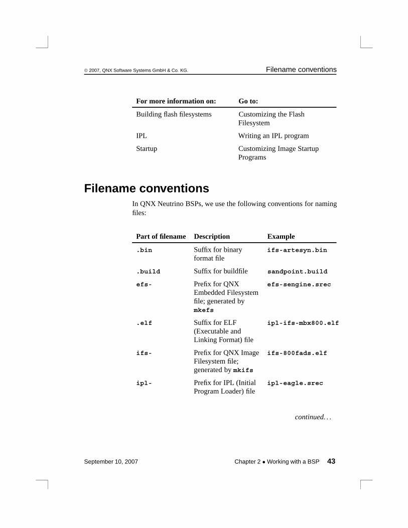
Filename conventionsIn QNX Neutrino BSPs, we use the following conventions for namingfiles:
Part of filename Description Example
.bin Suffix for binaryformat file
ifs-artesyn.bin
.build Suffix for buildfile sandpoint.build
efs- Prefix for QNXEmbedded Filesystemfile; generated bymkefs
efs-sengine.srec
.elf Suffix for ELF(Executable andLinking Format) file
ipl-ifs-mbx800.elf
ifs- Prefix for QNX ImageFilesystem file;generated by mkifs
ifs-800fads.elf
ipl- Prefix for IPL (InitialProgram Loader) file
ipl-eagle.srec
continued. . .
September 10, 2007 Chapter 2 • Working with a BSP 43

Filename conventions © 2007, QNX Software Systems GmbH & Co. KG.
Part of filename Description Example
.openbios Suffix for OpenBIOSformat file
ifs-walnut.openbios
.prepboot Suffix for MotorolaPRePboot format file
ifs-prpmc800.prepboot
.srec Suffix for S-recordformat file
ifs-malta.srec
44 Chapter 2 • Working with a BSP September 10, 2007
Chapter 3
Making an OS Image
In this chapter. . .Images, images, images 47What is an OS image? 47The OS image as a filesystem 48Configuring an OS image 49Building a flash filesystem image 61Embedding an image 70System configuration 75Debugging an embedded system 82
September 10, 2007 Chapter 3 • Making an OS Image 45

© 2007, QNX Software Systems GmbH & Co. KG. What is an OS image?
Making an OS image involves a number of steps, depending on thehardware and configuration of your target system.
In this chapter, we’ll take a look at the steps necessary to build an OSimage. Then we’ll examine the steps required to get that image to thetarget, whether it involves creating a boot disk/floppy, a network boot,or burning the image into an EPROM or flash device. We’ll alsodiscuss how to put together some sample systems to show you how touse the various drivers and resource managers that we supply.
For more information on using the various utilities described in thischapter, see the Utilities Reference.
Images, images, imagesIn the embedded Neutrino world, an “image” can mean either of thefollowing:
Image type Description
OS image A bootable or nonbootable structure thatcontains files; created by the mkifsutility.
Flash filesystem image A structure that can be used in aread-only, read/write, orread/write/reclaim flash filesystem;created by the mkefs utility.
What is an OS image?An OS image is simply a file. When you’ve created your executables(programs) that you want your embedded system to run, you need toplace them somewhere where they can be loaded from. An OS imageis the file that contains the OS, your executables, and any data filesthat might be related to your programs. Actually, you can think of theimage as a small “filesystem” — it has a directory structure and somefiles in it.
September 10, 2007 Chapter 3 • Making an OS Image 47

The OS image as a filesystem © 2007, QNX Software Systems GmbH & Co. KG.
An image can be bootable or nonbootable. A bootable image is onethat contains the startup code that the IPL can transfer control to (seethe chapter on customizing IPL programs in this book). Generally, asmall embedded system will have only the one (bootable) OS image.
A nonbootable image is usually provided for systems where aseparate, configuration-dependent setup may be required. Think of itas a second “filesystem” that has some additional files in it (we’lldiscuss this in more depth later). Since it’s nonbootable, this imagewill typically not contain the OS, startup file, etc.
The OS image as a filesystemAs previously mentioned, the OS image can be thought of as afilesystem. In fact, the image contains a small directory structure thattells procnto the names and positions of the files contained within it;the image also contains the files themselves. When the embeddedsystem is running, the image can be accessed just like any otherread-only filesystem:
# cd /proc/boot# ls.script ping cat data1 pidin
ksh ls ftp procnto devc-ser8250-ixp2400# cat data1This is a data file, called data1, contained in the image.Note that this is a convenient way of associating datafiles with your programs.
The above example actually demonstrates two aspects of having theOS image function as a filesystem. When we issued the ls command,the OS loaded ls from the image filesystem (pathname/proc/boot/ls). Then, when we issued the cat command, the OSloaded cat from the image filesystem as well, and opened the filedata1.
Let’s now take a look at how we configure the image to contain files.
48 Chapter 3 • Making an OS Image September 10, 2007
© 2007, QNX Software Systems GmbH & Co. KG. Configuring an OS image
Configuring an OS imageThe OS image is created by a program called mkifs (make imagef ilesystem), which accepts information from two main sources: itscommand line and a buildfile.
For more information, see mkifs in the Utilities Reference.
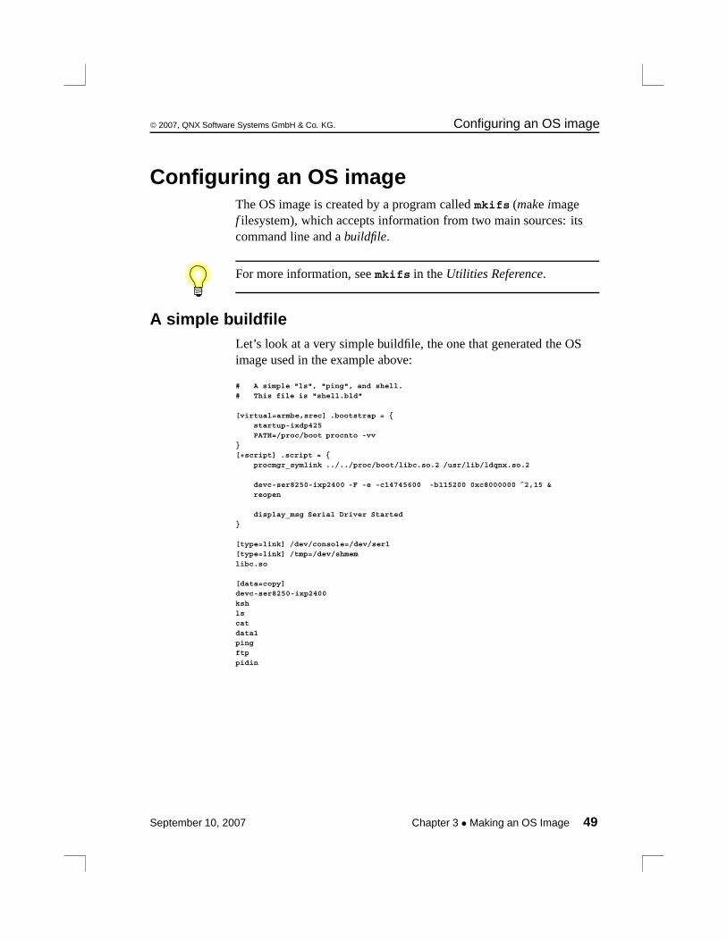
A simple buildfileLet’s look at a very simple buildfile, the one that generated the OSimage used in the example above:
# A simple "ls", "ping", and shell.# This file is "shell.bld"
[virtual=armbe,srec] .bootstrap = {startup-ixdp425PATH=/proc/boot procnto -vv
}[+script] .script = {
procmgr_symlink ../../proc/boot/libc.so.2 /usr/lib/ldqnx.so.2
devc-ser8250-ixp2400 -F -e -c14745600 -b115200 0xc8000000 ˆ2,15 &reopen
display_msg Serial Driver Started}
[type=link] /dev/console=/dev/ser1[type=link] /tmp=/dev/shmem
libc.so
[data=copy]devc-ser8250-ixp2400
kshlscat
data1pingftp
pidin
September 10, 2007 Chapter 3 • Making an OS Image 49

Configuring an OS image © 2007, QNX Software Systems GmbH & Co. KG.
In a buildfile, a pound sign (#) indicates a comment; anythingbetween it and the end of the line is ignored. Make sure there’s aspace between a buildfile command and the pound sign.
This buildfile consists of these sections:
• a bootfile — starting with [virtual=armbe,srec]
• a script — starting with [+script]
• a list of links and files to include in the image — starting with[type=link] /dev/console=/dev/ser1
Inline files
Although the three sections in the buildfile above seem to be distinct,in reality all three are similar in that they’re lists of files.
Notice also how the buildfile itself is structured:
optional_attributes filename optional_contents
For example, the line:
[virtual=armbe,srec] .bootstrap = {
has an attribute of [virtual=armbe,srec], a filename of.bootstrap, and an optional_contents part (from the = { to thecorresponding closing brace).
Let’s examine these elements in some detail.
The first part (starting with [virtual=armbe,srec]) specifies thata virtual address system is being built. The CPU type appears next;“armbe” indicates a big-endian ARM processor. Then after thecomma comes the name of the bootfile (srec).
The rest of the line specifies an inline file (as indicated by the openbrace) named “.bootstrap”, which consists of the following:
startup-ixdp425PATH=/proc/boot procnto -vv
50 Chapter 3 • Making an OS Image September 10, 2007
© 2007, QNX Software Systems GmbH & Co. KG. Configuring an OS image
The second part starts with the [+script] attribute — this tellsmkifs that the specified file is a script file, a sequence ofcommands—including the microkernel, procnto—that should beexecuted when the Process Manager has completed its startup.
Script files look just like regular shell scripts, except that:
• special modifiers can be placed before the actual commands to run
• some commands are builtin
• the script file’s contents are parsed by mkifs before being placedinto the image
In order to run a command, its executable must be available when thescript is executed. You can add the executable to the image or get itfrom a filesystem that’s started before the executable is required. Thelatter approach results in a smaller image.
In this case, the script file is, again, another inline file (again indicatedby the open brace). The file (which happens to be called “.script”)contains the following:
procmgr_symlink ../../proc/boot/libc.so.2 /usr/lib/ldqnx.so.2
devc-ser8250-ixp2400 -F -e -c14745600 -b115200 0xc8000000 ˆ2,15 &reopen
display_msg Serial Driver Started
This script file begins by creating a symbolic link to../../proc/boot/libc.so.2 called /usr/lib/ldqnx.so.2.Next the script starts a serial driver (devc-ser8250-ixp2400) inedited mode with hardware flow control disabled at a baud rate of115200 bps at a particular physical memory address. The script thendoes a reopen to redirect standard input, output, and error. The lastline simply displays a message.
September 10, 2007 Chapter 3 • Making an OS Image 51
Configuring an OS image © 2007, QNX Software Systems GmbH & Co. KG.
CAUTION: If you specify an ampersand (&) after the command line,the program runs in the background, and Neutrino doesn’t wait for theprogram to finish before continuing with the next line in the script.
If you don’t specify the ampersand, and the program doesn’t exit, thenthe rest of the script is never executed, and the system doesn’t becomefully operational. In particular, procnto doesn’t reap zombies thatget reparented to it, resulting in a system that accumulates zombieprocesses, all parented to procnto, that won’t go away until youreboot.
!
Generating the image
To generate the image file from our sample buildfile, you couldexecute the command:
mkifs shell.bld shell.ifs
This tells mkifs to use the buildfile shell.bld to create the imagefile shell.ifs.
Plain ordinary lists of filesLet’s return to our example. Notice the “list of files” (i.e. from“[type=link] /dev/console=/dev/ser1” to “pidin”).
Including files from different places
In the example above, we specified that the files at the end were to bepart of the image, and mkifs somehow magically found them.Actually, it’s not magic — mkifs simply looked for the environmentvariable MKIFS_PATH. This environment variable contains a list ofplaces to look for the files specified in the buildfile. If the environmentvariable doesn’t exist, then the following are searched in this order:
1 current working directory if the filename contains a slash (butdoesn’t start with one).
2 ${QNX_TARGET}/${PROCESSOR}/sbin
52 Chapter 3 • Making an OS Image September 10, 2007
© 2007, QNX Software Systems GmbH & Co. KG. Configuring an OS image
3 ${QNX_TARGET}/${PROCESSOR}/usr/sbin
4 ${QNX_TARGET}/${PROCESSOR}/boot/sys
5 ${QNX_TARGET}/${PROCESSOR}/bin
6 ${QNX_TARGET}/${PROCESSOR}/usr/bin
7 ${QNX_TARGET}/${PROCESSOR}/lib
8 ${QNX_TARGET}/${PROCESSOR}/lib/dll
9 ${QNX_TARGET}/${PROCESSOR}/usr/lib
10 ${QNX_TARGET}/${PROCESSOR}/usr/photon/bin
(The ${PROCESSOR} component is replaced with the name of theCPU, e.g. arm.)
Since none of the filenames that we used in our example starts withthe “/” character, we’re telling mkifs that it should search for files(on the host) within the path list specified by the MKIFS_PATHenvironment variable as described above. Regardless of where thefiles came from on the host, in our example they’ll all be placed onthe target under the /proc/boot directory (there are a few subtletieswith this, which we’ll come back to).
For our example, devc-con will appear on the target as the file/proc/boot/devc-con, even though it may have come from thehost as ${QNX_TARGET}/armbe/sbin/devc-con.
To include files from locations other than those specified in theMKIFS_PATH environment variable, you have a number of options:
• Change the MKIFS_PATH environment variable (use the shellcommand export MKIFS_PATH=newpath on the host).
• Modify the search path with the [search=] attribute.
• Specify the pathname explicitly (i.e. with a leading “/” character).
• Create the contents of the file in line.
September 10, 2007 Chapter 3 • Making an OS Image 53
Configuring an OS image © 2007, QNX Software Systems GmbH & Co. KG.
Modifying the search path
By specifying the [search=newpath] attribute, we can cause mkifsto look in places other than what the environment variableMKIFS_PATH specifies. The newpath component is acolon-separated list of pathnames and can include environmentvariable expansion. For example, to augment the existingMKIFS_PATH pathname to also include the directory /mystuff,you would specify:
[search=${MKIFS_PATH}:/mystuff]
Specifying the pathname explicitly
Let’s assume that one of the files used in the example is actuallystored on your development system as /release/data1. If yousimply put /release/data1 in the buildfile, mkifs would includethe file in the image, but would call it /proc/boot/data1 on thetarget system, instead of /release/data1.
Sometimes this is exactly what you want. But at other times you maywant to specify the exact pathname on the target (i.e. you may wish tooverride the prefix of /proc/boot). For example, specifying/etc/passwd would place the host filesystem’s /etc/passwd filein the target’s pathname space as /proc/boot/passwd— mostlikely not what you intended. To get around this, you could specify:
/etc/passwd = /etc/passwd
This tells mkifs that the file /etc/passwd on the host should bestored as /etc/passwd on the target.
On the other hand, you may in fact want a different source file (let’ssay /home/joe/embedded/passwd) to be the password file for theembedded system. In that case, you would specify:
/etc/passwd = /home/joe/embedded/passwd
54 Chapter 3 • Making an OS Image September 10, 2007

© 2007, QNX Software Systems GmbH & Co. KG. Configuring an OS image
Creating the contents of the file in line
For our tiny data1 file, we could just as easily have included it in line— that is to say, we could have specified its contents directly in thebuildfile itself, without the need to have a real data1 file residesomewhere on the host’s filesystem. To include the contents in line,we would have specified:
data1 = {This is a data file, called data1, contained in the image.Note that this is a convenient way of associating datafiles with your programs.}
A few notes. If your inline file contains the closing brace (“}”), thenyou must escape that closing brace with a backslash (“\”). This alsomeans that all backslashes must be escaped as well. To have an inlinefile that contains the following:
This includes a {, a }, and a \ character.
you would have to specify this file (let’s call it data2) as follows:
data2 = {This includes a {, a \}, and a \\ character.}
Note that since we didn’t want the data2 file to contain leadingspaces, we didn’t supply any in the inline definition. The following,while perhaps “better looking,” would be incorrect:
# This is wrong, because it includes leading spaces!data2 = {
This includes a {, a \}, and a \\ character.}
If the filename that you’re specifying has “weird” characters in it,then you must quote the name with double quote characters ("). Forexample, to create a file called I "think" so (note the spaces andquotation marks), you would have to specify it as follows:
"I \"think\" so" = ...
But naming files like this is discouraged, since the filenames aresomewhat awkward to type from a command line (not to mention thatthey look goofy).
September 10, 2007 Chapter 3 • Making an OS Image 55
Configuring an OS image © 2007, QNX Software Systems GmbH & Co. KG.
Specifying file ownership and permissions
The files that we included (in the example above) had the owner,group ID, and permissions fields set to whatever they were set to onthe host filesystem they came from. The inline files (data1 anddata2) got the user ID and group ID fields from the user who ran themkifs program. The permissions are set according to the user’sumask.
If we wanted to explicitly set these fields on particular files within thebuildfile, we would prefix the filenames with an attribute:
[uid=0 gid=0 perms=0666] file1[uid=5 gid=1 perms=a+xr] file2
This marks the first file (file1) as being owned by root (the user ID0), group zero, and readable and writable by all (the mode of octal666). The second file (file2) is marked as being owned by user ID5, group ID 1, and executable and readable by all (the a+xrpermissions).
When running on a Windows host, mkifs can’t get the execute (x),setuid (“set user ID”), or setgid (“set group ID”) permissions from thefile. Use the perms attribute to specify these permissions explicitly.You might also have to use the uid and gid attributes to set theownership correctly. To determine whether or not a utility needs tohave the setuid or setgid permission set, see its entry in the UtilitiesReference.
Notice how when we combine attributes, we place all of the attributeswithin one open-square/close-square set. The following is incorrect:
# Wrong way to do it![uid=0] [gid=0] [perms=0666] file1
If we wanted to set these fields for a bunch of files, the easiest way todo that would be to specify the uid, gid, and perms attributes on asingle line, followed by the list of files:
[uid=5 gid=1 perms=0666]file1
56 Chapter 3 • Making an OS Image September 10, 2007

© 2007, QNX Software Systems GmbH & Co. KG. Configuring an OS image
file2file3file4
which is equivalent to:
[uid=5 gid=1 perms=0666] file1[uid=5 gid=1 perms=0666] file2[uid=5 gid=1 perms=0666] file3[uid=5 gid=1 perms=0666] file4
Including a whole whack of files
If we wanted to include a large number of files, perhaps from apreconfigured directory, we would simply specify the name of thedirectory instead of the individual filenames. For example, if we had adirectory called /release_1.0, and we wanted all the files underthat directory to be included in the image, our buildfile would havethe line:
/release_1.0
This would put all the files that reside under /release_1.0 into/proc/boot on the target. If there were subdirectories under/release_1.0, then they too would be created under /proc/boot,and all the files in those subdirectories would also be included in thetarget.
Again, this may or may not be what you intend. If you really want the/release_1.0 files to be placed under /, you would specify:
/=/release_1.0
This tells mkifs that it should grab everything from the/release_1.0 directory and put it into a directory called /. Asanother example, if we wanted everything in the host’s/release_1.0 directory to live under /product on the target, wewould specify:
/product=/release_1.0
September 10, 2007 Chapter 3 • Making an OS Image 57
Configuring an OS image © 2007, QNX Software Systems GmbH & Co. KG.
The script file on the target
The script file stored on the target isn’t the same as the originalspecification of the script file within the buildfile. That’s because ascript file is “special” — mkifs parses the text commands in thescript file and stores only the parsed output on the target, not theoriginal ASCII text. The reason we did this was to minimize the workthat the process manager has to do at runtime when it starts up andprocesses the script file — we didn’t want to have to include acomplete shell interpreter within the process manager!
Bound multiprocessing attributesYou can now specify which CPU to bind processes when launchingprocesses from the startup script through the [CPU=] attribute.
The [CPU=] is used as any other attribute, and specifies the CPU onwhich to launch the following process (or , if the attribute is usedalone on a line without a command, sets the default CPU for allfollowing processes). The CPU is specified as a (Octal-based)processor number, a value of * resets this.
cpu=processorcpu=*
Example:
cpu=1
If, at boot time, the given CPU is not valid, a warning message will bedisplayed and the command will be launched without any runmaskrestriction. Note that due to a limitation in the boot image records,this syntax allows only the specification of a single CPU and not amore generic runmask.
Use the on utility to spawn a process within a fully specified runmask.
The bootstrap fileAlong the lines of the startup script file, our bootstrap specification:
[virtual=armbe,srec] .bootstrap = {startup-ixdp425PATH=/proc/boot procnto -vv
}
58 Chapter 3 • Making an OS Image September 10, 2007
© 2007, QNX Software Systems GmbH & Co. KG. Configuring an OS image
also constructs an inline file (.bootstrap) that contains two lines:startup-ixdp425 and PATH=/proc/boot procnto -vv.
You can bind in optional modules to procnto by using the[module=...] attribute. For example, to bind in the adaptivepartitioning scheduler, change the procnto line to this:
[module=aps] PATH=/proc/boot procnto -vv
• Optional modules to procnto were introduced in the QNXNeutrino Core OS 6.3.2.
• For more information about the adaptive partitioning scheduler,see the Adaptive Partitioning User’s Guide.
As with the script filename, the actual name of the bootstrap file isirrelevant. However, nowhere else in the buildfile did we specify thosetwo files — they’re included automatically when specified by a[virtual] or [physical] attribute.
The “virtual” attribute (and its sibling the “physical” attribute)specifies the target processor (in our example, the armbe part) and thebootfile (the srec part), a very small amount of code between the IPLand startup programs. The target processor is put into the environmentvariable $PROCESSOR and is used during pathname expansion.You can omit the target processor specification, in which case itdefaults to the same as the host processor. For example:
[virtual=bios] .bootstrap = {...
would assume an ARM target if you’re on an ARM host system.
Both examples find a file called $PROCESSOR/sys/bios.boot (the.boot part is added automatically by mkifs), and process it forconfiguration information.
September 10, 2007 Chapter 3 • Making an OS Image 59
Configuring an OS image © 2007, QNX Software Systems GmbH & Co. KG.
Compressing the image
While we’re looking at the bootstrap specification, it’s worthmentioning that you can apply the +compress attribute to compressthe entire image. The image is automatically uncompressed beforebeing started. Here’s what the first line would look like:
[virtual=armbe,srec +compress] .bootstrap = {
Specifying command-line options to mkifsAs mentioned above, you can also specify command-line options tomkifs. Since these command-line options are interpreted before theactual buildfile, you can add lines before the buildfile. You would dothis if you wanted to use a makefile to change the defaults of a genericbuildfile.
The following sample changes the address at which the image startsto 64 KB (hex 0x10000):
mkifs -l "[image=0x10000]" buildfile image
For more information, see mkifs in the Utilities Reference.
Listing the contents of an imageIf you’d like to see the contents of an image, you can use the dumpifsutility. The output from dumpifs might look something like this:
Offset Size Name0 100 Startup-header flags1=0x1 flags2=0 paddr_bias=0x80000000
100 a008 startup.*
a108 5c Image-header mountpoint=/a164 264 Image-directory---- ---- Root-dirent
---- 12 usr/lib/ldqnx.so.2 -> /proc/boot/libc.so---- 9 dev/console -> /dev/ser1a3c8 80 proc/boot/.scriptb000 4a000 proc/boot/procnto
55000 59000 proc/boot/libc.so.2---- 9 proc/boot/libc.so -> libc.so.2ae000 7340 proc/boot/devc-ser8250
b6000 4050 proc/boot/eshbb000 4a80 proc/boot/lsc0000 14fe0 proc/boot/data1
d5000 22a0 proc/boot/data2Checksums: image=0x94b0d37b startup=0xa3aeaf2
60 Chapter 3 • Making an OS Image September 10, 2007
© 2007, QNX Software Systems GmbH & Co. KG. Building a flash filesystem image
The more -v (“verbose”) options you specify to dumpifs, the moredata you’ll see.
For more information on dumpifs, see its entry in the UtilitiesReference.
Building a flash filesystem imageIf your application requires a writable filesystem and you have flashmemory devices in your embedded system, then you can use aNeutrino flash filesystem driver to provide a POSIX-compatiblefilesystem. The flash filesystem drivers are described in thefilesystems chapter of the System Architecture guide. The chapter oncustomizing the flash filesystem in this book describes how you canbuild a flash filesystem driver for your embedded system.
You have two options when creating a flash filesystem:
• Create a flash filesystem image file on the host system and thenwrite the image into the flash on the target.
• Run the flash filesystem driver for your target system and copyfiles into the flash filesystem on the target.
In this section we describe how to create a flash filesystem image fileusing the mkefs (for make embedded f ilesystem) utility and abuildfile. How to transfer the flash filesystem image onto your targetsystem is described in the “Embedding an image” section. For detailson how to use the flash filesystem drivers, see the Utilities Reference.
Using mkefsThe mkefs utility takes a buildfile and produces a flash filesystemimage file. The buildfile is a list of attributes and files to include in thefilesystem.
mkefs buildfile
The syntax of the buildfile is similar to that for mkifs, but mkefssupports a different set of attributes, including the following:
September 10, 2007 Chapter 3 • Making an OS Image 61

Building a flash filesystem image © 2007, QNX Software Systems GmbH & Co. KG.
block_size=bsize
Specifies the block size of the flash device being used; defaultsto 64 KB. We’ll talk about interleave considerations for flashdevices below.
max_size=msize
Specifies the maximum size of the flash device; is used to checkfor overflows. The default is 4 Gbytes.
spare_blocks=sblocks
Specifies the number of spare blocks that will be set aside forthe flash filesystem. If sblocks is set to 0, this implies a“read/write” flash filesystem, whereas a value greater than 0implies a “read/write/reclaim” filesystem. The default is1.Spare blocks also replace bad blocks, i.e. blocks that fail.)
min_size=tsize
Specifies the minimum size of the filesystem. If the resultantimage is smaller than tsize, the image is padded out to tsizebytes. The default is unspecified, meaning that the image won’tbe padded.
Refer to the Utilities Reference for a complete description of thebuildfile syntax and attributes supported by mkefs.
Here’s a very simple example of a buildfile:
[block_size=128k spare_blocks=1 filter=inflator/deflate]/home/ejm/products/sp1/callp/imagedir
In this example, the attributes specify that the flash devices have ablock size of 128 KB, that there should be one spare block, and thatall the files should be processed using the inflator and deflate
utilities, which will compress/decompress the files. A single directoryis given. Just as with mkifs, when we specify a directory, all files andsubdirectories beneath it are included in the resulting image. Most ofthe other filename tricks shown above for mkifs also apply to mkefs.
62 Chapter 3 • Making an OS Image September 10, 2007
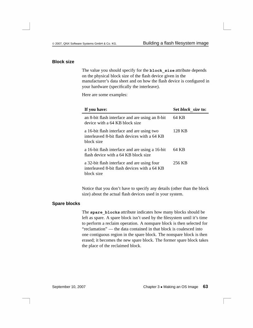
© 2007, QNX Software Systems GmbH & Co. KG. Building a flash filesystem image
Block size
The value you should specify for the block_size attribute dependson the physical block size of the flash device given in themanufacturer’s data sheet and on how the flash device is configured inyour hardware (specifically the interleave).
Here are some examples:
If you have: Set block_size to:
an 8-bit flash interface and are using an 8-bitdevice with a 64 KB block size
64 KB
a 16-bit flash interface and are using twointerleaved 8-bit flash devices with a 64 KBblock size
128 KB
a 16-bit flash interface and are using a 16-bitflash device with a 64 KB block size
64 KB
a 32-bit flash interface and are using fourinterleaved 8-bit flash devices with a 64 KBblock size
256 KB
Notice that you don’t have to specify any details (other than the blocksize) about the actual flash devices used in your system.
Spare blocks
The spare_blocks attribute indicates how many blocks should beleft as spare. A spare block isn’t used by the filesystem until it’s timeto perform a reclaim operation. A nonspare block is then selected for“reclamation” — the data contained in that block is coalesced intoone contiguous region in the spare block. The nonspare block is thenerased; it becomes the new spare block. The former spare block takesthe place of the reclaimed block.
September 10, 2007 Chapter 3 • Making an OS Image 63
Building a flash filesystem image © 2007, QNX Software Systems GmbH & Co. KG.
If you specify a spare block (i.e. for the spare_blocks attribute)equal to 0, then the flash filesystem driver won’t be able to reclaimspace — it won’t have any place to put the new copy of the data.Therefore, you’ll be left with a read/write filesystem, which willeventually fill up since there’s no way to reclaim space.
flashcmp utility
You can use the flashcmp utility to compress files in the flashfilesystem. You can do this from a shell or you can use the filterattribute to mkefs.
The flash filesystem drivers know how to transparently decompressfiles that have been compressed with flashcmp, which means thatyou can access compressed files in the flash filesystem without havingto decompress them first. This can result in significant space savings.But there’s a tradeoff to file access performance — compressed fileswill be accessed a bit slower.
Compressing filesThe file compression mechanism provided with our flash filesystem isa convenient way to cut flash memory costs for customers. The flashfilesystem uses popular deflate/inflate algorithms for fast and efficientcompression/decompression.
In short, the deflate algorithm is a combination of two algorithms.The first one takes care of removing data duplication in files; thesecond algorithm advantages data sequences that appear the mostoften by giving them shorter symbols.
Those two algorithms combined provide excellent losslesscompression of data and executable files. The inflate algorithm, whichis actually part of the flash filesystem per se, reverses what the deflatealgorithm does.
64 Chapter 3 • Making an OS Image September 10, 2007
© 2007, QNX Software Systems GmbH & Co. KG. Building a flash filesystem image
Abstraction layer
The flash filesystem never compresses any files. It only detectscompressed files on the media and decompresses them as they areaccessed. An abstraction layer embedded in the flash filesystem codeachieves efficiency and preserves POSIX compliance. Specialcompressed data headers on top of the flash files provide fast seektimes.
This layering is quite straightforward. Specific I/O functions includehandling the three basic access calls for compressed files:
• read()
• lseek()
• lstat()
The compression headers contain a synchronization cue, flags,compressed size, and normal size for the data that follows the header.These headers can be used by the three basic access calls to readdecompressed data, seek into the file using a virtual offset, and findthe effective size of the file.
Two sizes
This is where compression gets tricky. A compressed file will havetwo sizes:
• virtual size — this is, for the end user, the real size of thedecompressed data.
• media size — the size that the file actually occupies on the media.
As a convenience, our flash filesystems offer a handy namespace thattotally replicates the regular flash file’s namespace, but gives themedia sizes when the files are stat()’ed (rather than the virtual oreffective size). Using this new namespace, files are neverdecompressed, so read operations will yield raw compressed datainstead of the decompressed data. This namespace is accessible bydefault through the .cmp mountpoint directory, right under theregular flash mountpoint.
September 10, 2007 Chapter 3 • Making an OS Image 65

Building a flash filesystem image © 2007, QNX Software Systems GmbH & Co. KG.
For instance, running the disk usage utility du would be practicallymeaningless under a flash directory with data that is decompressed onthe fly. It wouldn’t reflect flash media usage at all. But running the duutility under .cmp would render a better approximation of mediausage.
As mentioned earlier, you can compress files by using any of thesemethods:
• mkefs utility
• flashcmp utility
The first method, which is the high-runner case, is to use the mkefsutility. The flashcmp utility can be used as a filter for mkefs tocompress the files that get built into the flash filesystem. The files canalso be pre-compressed by the flashcmp utility — this will bedetected by mkefs and the data will be put on the flash filesystemwith the proper information. What information? A simple bit thattells the flash filesystem that the file should be handled by the flashdecompression layer.
Compression example using mkefs
This line builds a 16-megabyte filesystem with compression:
[block_size=128K spare_blocks=1 min_size=16m filter=flashcmp]/bin/
The mkefs utility detects a compression signature in the files listed inthe buildfile. This means that when files are precompressed, the filtercan be omitted. When this signature is detected, the proper bit is set inthe metadata area for on-the-fly decompression.
Compression example using flashcmp
The second method is to put compressed files on the media by usingflashcmp, but on board, straight with the flash filesystem. This iswhere the .cmp mountpoint is reused. Any file created under thismountpoint will have the compressed attribute bit. Needless to say,these files should be written using the compression headers, which theflashcmp utility does well.
66 Chapter 3 • Making an OS Image September 10, 2007

© 2007, QNX Software Systems GmbH & Co. KG. Building a flash filesystem image
In this example, we use flashcmp at the command line to compressthe ls file from the image filesystem into a flash filesystem:
$ flashcmp /proc/boot/ls > /fs0p0/.cmp/ls
Note that the .cmp mountpoint is used for the flash filesystem. Thistells the flash filesystem to set the compression bit in the metadataarea, enabling further decompression on the fly.
Compression rulesYou use the .cmp mountpoint to create previously compressed files,write previously compressed data, and check the size of compressedfiles. If you read a file from this mountpoint, the file won’t bedecompressed for you, as it is in the regular mountpoint. Now this iswhere we start talking about rules. All this reading and getting thesize of files is fairly simple; things get ugly when it’s time to writethose files.
1 When you write to a file created under the .cmp mountpoint,the data must be compressed.
2 You can’t write all over the place! Although the flash filesystemsupports random writes, the same is not true for compressedfiles.
3 Only appends are permitted when writing to a file created fromthe .cmp mountpoint. This has to be clear and respected,because the flash filesystem will reject any random writes tocompressed files.
4 The flash filesystem will never transparently compress any data.
5 If compressed data needs to be put on the flash during the lifeof a product, this data has to be precompressed.
Writing uncompressed data to a compressed file?
What if you need to write uncompressed data to a compressed file?You can do this, but it has to be from the regular mountpoint. And theappend-only rule applies for this file as well.
September 10, 2007 Chapter 3 • Making an OS Image 67
Building a flash filesystem image © 2007, QNX Software Systems GmbH & Co. KG.
Writing uncompressed data to a compressed file can be quitewasteful, because the uncompressed data will still be encapsulatedinto compressed headers, so a layer of code will be used for nothing.This means that at system design time, files that are meant to bewritable during the product life should not be compressed. Preferably,compressed files will remain read-only.
As a convenience, though, it’s still possible to append compressed oruncompressed data to compressed files. But we have to emphasizethat this might not always be the most efficient way to store data.Actually, the compression algorithms need a minimum data set to beable to compress, so the result has to be good enough to justify theheader abstraction overhead. Buffering isn’t possible withcompressed files, so there can’t be any assumptions for limitedoverhead when appending to compressed files.
Although it’s possible to write uncompressed data without the headeroverhead to a compressed file (provided if done from the .cmpnamespace), this isn’t a very good idea. The file will loose thecapability of rendering virtual uncompressed size and will becomeunseekable to positions after the first chunk of uncompressed data.The file data will still be readable, but the lost POSIX functionalityshould dissuade you from trying this.
The exception
So those are the rules, and here is the exception. Truncation is aspecial case. If a compressed file is opened with O_TRUNC from theregular virtual namespace, the file status will become just as if it werecreated from this namespace. This gives you full POSIX capabilitiesand no compression with accompanying restrictions.
The opposite is true: If a non-compressed file is opened withtruncation on the .cmp side, then compression rules apply. By theway, the ftruncate() functionality isn’t provided with compressedfiles, but is supported with regular files.
68 Chapter 3 • Making an OS Image September 10, 2007

© 2007, QNX Software Systems GmbH & Co. KG. Building a flash filesystem image
Buffer size
The buffer size is also selectable. This buffer represents thedecompressed data size that will be associated with each compressionheader. Of course, a larger buffer size might allow bettercompression, but RAM usage will be increased for the flashfilesystem driver. The default buffer size is 4 KB.
On a slightly different note, don’t be tempted to reuse the flashfilesystem as a decompression engine over a block-oriented or anetwork filesystem. These filesystems are often available in veryhigh-storage capacity and high-bandwidth formats. Compression overthese media is pure overkill and will always be a waste of CPUresources. The flash filesystem with compression is really meant forrestrained systems — the best approach for long-term life of a productis to read Moore’s Law* carefully. This law is true for flash as well,so plan ahead.
* In 1965, Intel co-founder Gordon Moore observed that the pace ofmicrochip technology change is such that the amount of data storagea microchip can hold doubles every year.
Design considerationsAlways consider the slowdown of compressed data access andincreased CPU usage when designing a system. We’ve seen systemswith restricted flash budget increase their boot time by large factorswhen using compression.
Inflator/deflate utilities
To compress files, you can also use the inflator and deflate pairof utilities, which can compress/decompress files for any filesystem,including flash. For details, see their entries in the Utilities Reference.
September 10, 2007 Chapter 3 • Making an OS Image 69
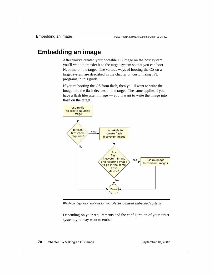
Embedding an image © 2007, QNX Software Systems GmbH & Co. KG.
Embedding an imageAfter you’ve created your bootable OS image on the host system,you’ll want to transfer it to the target system so that you can bootNeutrino on the target. The various ways of booting the OS on atarget system are described in the chapter on customizing IPLprograms in this guide.
If you’re booting the OS from flash, then you’ll want to write theimage into the flash devices on the target. The same applies if youhave a flash filesystem image — you’ll want to write the image intoflash on the target.
Use mkifs to create Neutrino
image
No
YesIs flash
filesystemrequired?
Use mkefs tocreate flash
filesystem image
No
Yes
Areflash
filesystem imageand Neutrino imageto go in the same
flashdevice?
Done
Use mkimageto combine images
Flash configuration options for your Neutrino-based embedded systems.
Depending on your requirements and the configuration of your targetsystem, you may want to embed:
70 Chapter 3 • Making an OS Image September 10, 2007
© 2007, QNX Software Systems GmbH & Co. KG. Embedding an image
• the IPL
• the boot image
• the boot image and other image filesystem
• the boot image and flash filesystem
• some other combination of the above.
Also, you may wish to write the boot image and the flash filesystemon the same flash device or different devices. If you want to write theboot image and the flash filesystem on the same device, then you canuse the mkimage utility to combine the image files into a single imagefile.
During the initial development stages, you’ll probably need to writethe image into flash using a programmer or a download utility. Lateron if you have a flash filesystem running on your target, you can thenwrite the image file into a raw flash partition.
If your programmer requires the image file to be in some format otherthan binary, then you can use the mkrec utility to convert the imagefile format.
Combining image files using mkimageThe mkimage utility combines multiple input image files into a singleoutput image file. It recognizes which of the image files contains theboot image and will place this image at the start. Note that instead ofusing mkimage, some developers rely on a flash programmer to burnthe separate images with appropriate alignment.
For example:
mkimage nto.ifs fs.ifs > flash.ifs
will take the nto.ifs and fs.ifs image files and output them to theflash.ifs file.
If you want more control over how the image files are combined, youcan use other utilities, such as:
September 10, 2007 Chapter 3 • Making an OS Image 71
Embedding an image © 2007, QNX Software Systems GmbH & Co. KG.
• cat
• dd
• mkrec
• objcopy
Combining image files using the IDE
You’ll use the System Builder to generate OS images for your targetboard’s RAM or flash. You can create:
• an OS image
• a Flash image
• a combined image.
For more information about this process, please see thedocumentation that comes with the QNX Momentics IDE.
Converting images using mkrecThe mkrec utility takes a binary image file and converts it to eitherMotorola S records or Intel hex records, suitable for a flash orEPROM programmer.
For example:
mkrec -s 256k flash.ifs > flash.srec
will convert the image file flash.ifs to an S-record format filecalled flash.srec. The -s 256k option specifies that the EPROMdevice is 256 KB in size.
If you have multiple image files that you wish to download, then youcan first use mkimage to combine the image files into a single filebefore downloading. Or, your flash/EPROM programmer may allowyou to download multiple image files at different offsets.
72 Chapter 3 • Making an OS Image September 10, 2007
© 2007, QNX Software Systems GmbH & Co. KG. Embedding an image
Transferring an image to flashThere are many ways to transfer your image into your flash:
• Use an EPROM burner that supports your socketed flash.
• Use a flash burner that supports onboard flash via a special bus,such as JTAG.
• Use a low-level monitor or a BIOS page with a flash burncommand.
• Use the flash filesystem raw mountpoints.
The details on how to transfer the image with anything other than thelast method is beyond the scope of this document. Using the rawmountpoint is a convenient way that comes bundled with your flashfilesystem library. You can actually read and write raw partitions justlike regular files, except that when the raw mountpoint is involved,remember to:
• go down one level in the abstraction ladder
• perform the erase commands yourself.
For the sake of this discussion, we can use the devf-ram driver. Thisdriver simulates flash using regular memory. To start it, log in asroot and type:
# devf-ram &
You can use the flashctl command to erase a partition. You don’tneed to be root to do this. For instance:
$ flashctl -p /dev/fs0 -e
CAUTION: Be careful when you use this command. Make sure youaren’t erasing something important on your flash — like your BIOS!!On normal flash, the flashctl command on a raw partition shouldtake a while (about one second for each erase block). This commanderases the /dev/fs0 raw flash array. Try the hd command on thisnewly erased flash array; everything should be 0xFF:
September 10, 2007 Chapter 3 • Making an OS Image 73
Embedding an image © 2007, QNX Software Systems GmbH & Co. KG.
$ hd /dev/fs00000000: ff ff ff ff ff ff ff ff ff ff ff ff ff ff ff ff ................*
For more information on flashctl, see the Utilities Reference.
Let’s make a dummy IPL for the purpose of this example:
$ echo Hello, World! > ipl$ mkrec -s 128k -f full ipl > ipl_imageReset jmps to 0x1FFE0 (jmp 0xFFED)ROM offset is 0x1FFE0
Of course, this IPL won’t work for real — it’s just for trying out theflash filesystem. In any event, an IPL wouldn’t be very useful inRAM. Let’s make a dummy flash filesystem for the purpose of thisexample (the ˆD means Ctrl-D):
$ mkefs -v - flash_image[block_size=128k spare_blocks=1 min_size=384k]/bin/ls/bin/catˆDwriting directory entry ->writing file entry -> ls **writing file entry -> cat *Filesystem size = 384Kblock size = 128K1 spare block(s)
This flash filesystem actually works (unlike the IPL). Now, the flashpartition images can be transfered to the flash using any file-transferutility (such as cp or ftp). We have an IPL image created withmkrec (and properly padded to an erase block boundary) and a flashimage created with mkefs, so we can use cat to combine andtransfer both images to the flash:
$ cat ipl_image flash_image > /dev/fs0
If you use the hd utility on the raw mountpoint again, you’ll see thatyour flash that had initially all bits set to ones (0xFF) now containsyour partition images. To use the flash filesystem partition, you needto slay the driver and start it again so it can recognize the partitionsand mount them. For instance, with devf-ram:
74 Chapter 3 • Making an OS Image September 10, 2007
© 2007, QNX Software Systems GmbH & Co. KG. System configuration
$ slay devf-ram$ devf-ram &
From this point, you have a /fs0p1 mountpoint that’s in fact adirectory and contains the files you specified with mkefs to createyour flash image. There’s no /fs0p0, because the boot image isn’trecognized by the flash filesystem. It’s still accessible as a rawmountpoint via /dev/fs0p0. You can do the same operations on/dev/fs0p0 that you could do with /dev/fs0. Even /dev/fs0p1
is accessible, but be careful not to write to this partition whileapplications are using the flash filesystem at /fs0p1. Try:
$ /fs0p1/ls /fs0p1
You’ve just executed ls from your flash filesystem and you’ve listedits contents. To conclude, let’s say that what we did in this example isa good starting point for when you customize the flash filesystem toyour own platforms. These baby steps should be the first steps tousing a full-blown filesystem on your target.
System configurationIn this section, we’ll look at some of the ways you can configureNeutrino systems. Please refer to the Sample Buildfiles appendix inthis guide for more detailed examples.
What you want to do will, of course, depend on the type of systemyou’re building. Our purpose in this section is to offer some generalguidelines and to help clarify which executables should be used inwhich circumstances, as well as which shared libraries are requiredfor their respective executables.
The general procedure to set up a system is as follows:
1 Establish an output device.
2 Run drivers.
3 Run applications.
September 10, 2007 Chapter 3 • Making an OS Image 75
System configuration © 2007, QNX Software Systems GmbH & Co. KG.
Establishing an output deviceOne of the very first things to do in a buildfile is to start a driver thatyou then redirect standard input, output, and error to. This allows allsubsequent drivers and applications to output their startup messagesand any diagnostics messages they may emit to a known place whereyou can examine the output.
Generally, you’d start either the console driver or a serial port driver.The console driver is used when you’re developing on a fairlycomplete “desktop” type of environment; the serial driver is suitablefor most “embedded” environments.
But you may not even have any such devices in your deeplyembedded system, in which case you would omit this step. Or youmay have other types of devices that you can use as your outputdevice, in which case you may require a specialized driver (that yousupply). If you don’t specify a driver, output will go to the debugoutput driver provided by the startup code.
A simple desktop example
This example starts the standard console driver in edited mode (the -eoption, which is the default). To set up the output device, you wouldinclude the driver in your startup script (the [+script] file). Forexample:
devc-con -e &reopen /dev/con1
The following starts the 8250 serial port driver in edited mode (the -eoption), with an initial baud rate of 115200 baud (the -b option):
devc-ser8250 -e -b115200 &reopen /dev/ser1
In both cases, the reopen command causes standard input, output,and error to be redirected to the specified pathname (either/dev/con1 or /dev/ser1 in the above examples). This redirectionholds until otherwise specified with another reopen command.
76 Chapter 3 • Making an OS Image September 10, 2007
© 2007, QNX Software Systems GmbH & Co. KG. System configuration
The reopen used above is a mkifs internal command, not the shellbuiltin command of the same name.
Running drivers/filesystemsThe next thing you’ll want to run are the drivers and/or filesystemsthat will give you access to the hardware. Note that the console orserial port that we installed in the previous section is actually anexample of such a driver, but it was a special case in that it shouldgenerally be the first one.
We support several types of drivers/filesystems, including:
• disk drivers (devb-*)
• flash filesystems (devf-*)
• network drivers (devn-*)
• input drivers (devi-*)
• USB drivers (devu-*)
• filesystems (fs-*)
Which one you install first is generally driven by where yourexecutables reside. One of the goals for the image is to keep it small.This means that you generally don’t put all the executables and sharedlibraries you plan to load directly into the image — instead, you placethose files into some other medium (whether a flash filesystem,rotating disk, or a network filesystem). In that case, you should startthe appropriate driver to get access to your executables. Once youhave access to your executables on some medium, you would thenstart other drivers from that medium.
The alternative, which is often found in deeply embedded systems, isto put all the executables and shared libraries directly into the image.You might want to do this if there’s no secondary storage medium orif you wanted to have everything available immediately, without theneed to start a driver.
September 10, 2007 Chapter 3 • Making an OS Image 77
System configuration © 2007, QNX Software Systems GmbH & Co. KG.
Let’s examine the steps required to start the disk, flash, and networkdrivers. All these drivers share a common feature: they rely on oneprocess that loads one or more .so files, with the particular .so filesselected either via the command line of the process or via automaticconfiguration detection.
Since the various drivers we’re discussing here use .so files (not justtheir own driver-specific ones, but also standard ones like the Clibrary), these .so files must be present before the driver starts.Obviously, this means that the .so file cannot be on the samemedium as the one you’re trying to start the driver for! Werecommend that you put these .so files into the image filesystem.
Disk drivers
The first thing you need to determine is which hardware you havecontrolling the disk interface. We support a number of interfaces,including various flavors of SCSI controllers and the EIDE controller.For details on the supported interface controllers, see the variousdevb-* entries in the Utilities Reference.
The only action required in your buildfile is to start the driver (e.g.devb-aha7). The driver will then dynamically load the appropriatemodules (in this order):
1 libcam.so — Common Access Method library
2 cam-*.so — Common Access Method module(s)
3 io-blk.so — block I/O module
4 fs-*.so — filesystem personality module(s)
The CAM .so files are documented under cam-* in the UtilitiesReference. Currently, we support CD-ROMs (cam-cdrom.so), harddisks (cam-disk.so), and optical disks (cam-optical.so).
The io-blk.so module is responsible for dealing with a disk on ablock-by-block basis. It includes caching support.
78 Chapter 3 • Making an OS Image September 10, 2007
© 2007, QNX Software Systems GmbH & Co. KG. System configuration
The fs-* modules are responsible for providing the high-levelknowledge about how a particular filesystem is structured. Wecurrently support the following:
Filesystem Module
ISO-9660 CD-ROM fs-cd.so
CIFS (Common Internet File System) fs-cifs
MS-DOS fs-dos.so
Linux fs-ext2.so
NFS (Network File System) fs-nfs2, fs-nfs3
Neutrino Package Filesystem fs-pkg
QNX4 fs-qnx4.so
Flash filesystems
To run a flash filesystem, you need to select the appropriate flashdriver for your target system. For details on the supported flashdrivers, see the various devf-* entries in the Utilities Reference.
The devf-generic flash driver that can be thought of as a universaldriver whose capabilities make it accessible to most flash devices.
The flash filesystem drivers don’t rely on any flash-specific .so files,so the only module required is the standard C library (libc.so).
Since the flash filesystem drivers are written for specific targetsystems, you can usually start them without command-line options;they’ll find the flash for the specific system they were written for.
Network drivers
Network services are started from the io-net command, which isresponsible for loading in the required .so files.
September 10, 2007 Chapter 3 • Making an OS Image 79
System configuration © 2007, QNX Software Systems GmbH & Co. KG.
For dynamic control of network drivers, you can simply use mountand umount to start and stop drivers at the command line. Forexample:
mount -T io-net devn-ne2000.so
For more information, see mount in the Utilities Reference.
Two levels of .so files are started, based on the command-lineoptions given to io-net:
• -d specifies driver .so files
• -p specifies protocol .so files.
The -d option lets you choose the hardware driver that knows how totalk to a particular card. For example, choosing -d ne2000 willcause io-net to load devn-ne2000.so to access anNE-2000-compatible network card. You may specify additionalcommand-line options after the -d, such as the interrupt vector to beused by the card.
The -p option lets you choose the protocol driver that deals with aparticular protocol. For example, choosing -p ttcpip will causeio-net to load npm-ttcpip.so, which will provide the tinyTCP/IP stack. As with the -d option, you would specifycommand-line options after the -p for the driver, such as the IPaddress for a particular interface.
For more information about network services, see the devn-*,io-net, and npm-* entries in the Utilities Reference.
Network filesystems
We support two types of network filesystems:
• NFS (fs-nfs2 /fs-nfs3), which allows file access over anetwork to a UNIX or other system running an NFS server.
80 Chapter 3 • Making an OS Image September 10, 2007
© 2007, QNX Software Systems GmbH & Co. KG. System configuration
• CIFS (fs-cifs), which allows file access over a network to aWindows 98 or NT system or to a UNIX system running an SMBserver.
The CIFS protocol makes no attempt to conform to POSIX.
Although NFS is primarily a UNIX-based filesystem, you may findsome versions of NFS available for Windows.
Running applicationsThere’s nothing special required to run your applications. Generally,they’ll be placed in the script file after all the other drivers havestarted. If you require a particular driver to be present and “ready,”you would typically use the waitfor command in the script.
Here’s an example. An application called peelmaster needs to waitfor a driver (let’s call it driver-spud) to be ready before it shouldstart. The following sequence is typical:
driver-spud &waitfor /dev/spudpeelmaster
This causes the driver (driver-spud) to be run in the background(specified by the ampersand character). The expectation is that whenthe driver is ready, it will register the pathname /dev/spud. Thewaitfor command tries to stat() the pathname /dev/spudperiodically, blocking execution of the script until the pathnameappears or a predetermined timeout has occurred. Once the pathnameappears in the pathname space, we assume that the driver is ready toaccept requests. At that point, the waitfor will unblock, and the nextprogram in the list (in our case, peelmaster) will execute.
Without the waitfor command, the peelmaster program wouldrun immediately after the driver was started, which could causepeelmaster to miss the /dev/spud pathname and fail.
September 10, 2007 Chapter 3 • Making an OS Image 81
Debugging an embedded system © 2007, QNX Software Systems GmbH & Co. KG.
Debugging an embedded systemWhen you’re developing embedded systems under some operatingsystems, you often need to use a hardware debugger, a physicaldevice that connects to target hardware via a JTAG (Joint Test ActionGroup) interface. This is necessary for development of drivers, andpossibly user applications, because they’re linked into the samememory space as the kernel. If a driver or application crashes, thekernel and system may crash as a result. This makes using softwaredebuggers difficult, because they depend on a running system.
Debugging target systems with Neutrino is different because itsarchitecture is significantly different from other embeddable realtimeoperating systems:
• All Neutrino applications (including drivers) run in their ownmemory-protected virtual address space. This has the advantagethat the software is more reliable and fault tolerant. However,conventional hardware debuggers rely on decoding physicalmemory addresses, making them incompatible with debugginguser applications based in a virtual memory environment.
• Neutrino lets you develop multithreaded applications, whichhardware debuggers generally don’t support.
Under Neutrino, you typically use:
• a hardware debugger for the IPL and startup
• a software debugger for the rest of the software
In other words, you rarely have to use a JTAG hardware debugger,especially if you’re using one of our board support packages.
pdebug software debugging agentWe provide a software debugging agent called pdebug that makes iteasier for you to debug system drivers and user applications. Thepdebug agent runs on the target system and communicates with thehost debugger over a serial or Ethernet connection.
82 Chapter 3 • Making an OS Image September 10, 2007
© 2007, QNX Software Systems GmbH & Co. KG. Debugging an embedded system
For more information, see “The process-level debug agent” in theCompiling and Debugging chapter of the Programmer’s Guide.
Hardware debuggers and NeutrinoThe major constraint of using pdebug is that the kernel must alreadybe running on the target. In other words, you can’t use pdebug untilthe IPL and startup have successfully started the kernel.
However, the IPL and startup program run with the CPU in physicalmode, so you can use conventional hardware debuggers to debugthem. This is the primary function of the JTAG debugger throughoutthe Neutrino software development phase. You use the hardwaredebugger to debug the BSP (IPL and startup), and pdebug to debugdrivers and applications once the kernel is running. You can also use ahardware debugger to examine registers and view memory while thekernel and applications are running, if you know the physicaladdresses.
If hardware debuggers, such as SH or AMC have builtin Neutrinoawareness, you can use a JTAG to debug applications. Thesedebuggers can interpret kernel information as well as perform thenecessary translation between virtual and physical memory addressesto view application data.
Producing debug symbol information for IPL and startupYou can use hardware debuggers to debug Neutrino IPL and startupprograms without any extra information. However, in this case, you’relimited to assembly-level debugging, and assembler symbols such assubroutine names aren’t visible. To perform full source-leveldebugging, you need to provide the hardware debugger with thesymbol information and C source code.
This section describes the steps necessary to generate the symbol anddebug information required by a hardware debugger for source-leveldebugging. The steps described are based on the PPC (PowerPC)Board Support Package available for Neutrino 6.3.0 for both IPL andstartup of the Motorola Sandpoint MPC750 hardware referenceplatform.
September 10, 2007 Chapter 3 • Making an OS Image 83
Debugging an embedded system © 2007, QNX Software Systems GmbH & Co. KG.
The examples below are described for a Neutrino 6.3 self-hostedenvironment, and assume that you’re logged in on the developmenthost with root privileges.
Generating IPL debug symbols
To generate symbol information for the IPL, you must recompile boththe IPL library and the Sandpoint IPL with debug information. Thegeneral procedure is as follows:
1 Modify the IPL source.
2 Build the IPL library and Sandpoint IPL.
3 Burn the IPL into the flash memory of the Sandpoint boardusing a flash burner or JTAG.
4 Modify the sandpoint.lnk file to output ELF format.
5 Recompile the IPL library and Sandpoint IPL source withdebug options.
6 Load the Sandpoint IPL ELF file containing debug informationinto the hardware debugger.
Be sure to synchronize the source code, the IPL burned into flash, andthe IPL debug symbols.
To build the IPL library with debug information:
# cd bsp_working_dir/src/hardware/ipl/lib/ppc/a.be# make clean# make CCOPTS=-g# cp libipl.a bsp_working_dir/sandpoint/install/ppcbe/lib# make install
The above steps recompile the PowerPC IPL library (libipl.a) withDWARF debug information and copy this library to the Sandpointinstall directory. The Sandpoint BSP is configured to look for thislibrary first in its install directory. The make install is optional,and copies libipl.a to /ppcbe/usr/lib.
84 Chapter 3 • Making an OS Image September 10, 2007
© 2007, QNX Software Systems GmbH & Co. KG. Debugging an embedded system
The Sandpoint BSP has been set up to work with SREC format files.However, to generate debug and symbol information to be loaded intothe hardware debugger, you must generate ELF-format files.
Modify the sandpoint.lnk file to output ELF format:
# cd bsp_working_dir/sandpoint/src/hardware/ipl/boards/sandpoint
Edit the file sandpoint.lnk, changing the first lines from:
TARGET(elf32-powerpc)OUTPUT_FORMAT(srec)ENTRY(entry_vec)
to:
TARGET(elf32-powerpc)OUTPUT_FORMAT(elf32-powerpc)ENTRY(entry_vec)
You can now rebuild the Sandpoint IPL to produce symbol and debuginformation in ELF format. To build the Sandpoint IPL with debuginformation:
# cd bsp_working_dir/sandpoint/src/hardware/ipl/boards/sandpoint/ppc/be# make clean# make CCOPTS=-g
The ipl-sandpoint file is now in ELF format with debug symbolsfrom both the IPL library and Sandpoint IPL.
To rebuild the BSP, you need to change the sandpoint.lnk fileback to outputting SREC format. It’s also important to keep the IPLthat’s burned into the Sandpoint flash memory in sync with thegenerated debug information; if you modify the IPL source, you needto rebuild the BSP, burn the new IPL into flash, and rebuild the IPLsymbol and debug information.
You can use the objdump utility to view the ELF information. Forexample, to view the symbol information contained in theipl-sandpoint file:
# objdump -t ipl-sandpoint | less
September 10, 2007 Chapter 3 • Making an OS Image 85
Debugging an embedded system © 2007, QNX Software Systems GmbH & Co. KG.
You can now import the ipl-sandpoint file into a hardwaredebugger to provide the symbol information required for debugging.In addition, the hardware debugger needs the source code listingsfound in the following directories:
• bsp_working_dir/sandpoint/src/hardware/ipl/boards/sandpoint
• bsp_working_dir/src/hardware/ipl/lib
• bsp_working_dir/src/hardware/ipl/lib/ppc
Generating startup debug symbols
To generate symbol information for startup, you must recompile boththe startup library and the Sandpoint startup with debug information.The general procedure is as follows:
1 Modify the startup source.
2 Build the startup library and Sandpoint startup with debuginformation.
3 Rebuild the image and symbol file.
4 Load the symbol file into the hardware debugger program.
5 Transfer the image to the Sandpoint target (burn into flash,transfer over a serial connection).
To build the startup library with debug information:
# cd bsp_working_dir/src/hardware/startup/lib/ppc/a.be# make clean
# make CCOPTS=-g# cp libstartup.a bsp_working_dir/sandpoint/install/ppcbe/lib# make install
The above steps recompile the PowerPC startup library(libstartup.a) with DWARF debug information and copy thislibrary to the Sandpoint install directory. The Sandpoint BSP isconfigured to look for this library first in its install directory. Themake install is optional, and copies libstartup.a to/ppcbe/usr/lib.
To build the Sandpoint startup with debugging information:
86 Chapter 3 • Making an OS Image September 10, 2007
© 2007, QNX Software Systems GmbH & Co. KG. Debugging an embedded system
# cd bsp_working_dir/sandpoint/src/hardware/startup/boards/sandpoint/ppc/be# make clean# make CCOPTS=-g
# make install
The above steps generate the file startup-sandpoint with symbol anddebug information. Again, you can use the -gstabs+ debug optioninstead of -g. The make install is necessary, and copiesstartup-sandpoint into the Sandpoint install directory,bsp_working_dir/sandpoint/install/ppcbe/boot/sys.
You can’t load the startup-sandpoint ELF file into the hardwaredebugger to obtain the debug symbols, because the mkifs utility addsan offset to the addresses defined in the symbols according to theoffset specified in the build file.
Modify the build file to include the +keeplinked attribute forstartup:
# cd bsp_working_dir/sandpoint/images
Modify the startup line of your build file to look like:
[image=0x10000][virtual=ppcbe,binary +compress] .bootstrap = {
[+keeplinked] startup-sandpoint -vvv -D8250PATH=/proc/boot procnto-600 -vv
}
The +keeplinked option makes mkifs generate a symbol file thatrepresents the debug information positioned within the imagefilesystem by the specified offset.
To rebuild the image to generate the symbol file:
# cd bsp_working_dir/sandpoint/images# make clean
Then, if you’re using one of the provided .build files:
# make all
otherwise:
# mkifs -v -r ../install myfile.build image
September 10, 2007 Chapter 3 • Making an OS Image 87

Debugging an embedded system © 2007, QNX Software Systems GmbH & Co. KG.
These commands create the symbol file, startup-sandpoint.sym.You can use the objdump utility to view the ELF information.
To view the symbol information contained in thestartup-sandpoint.sym file:
# objdump -t startup-sandpoint.sym | less
You can now import the startup-sandpoint.sym file into ahardware debugger to provide the symbol information required fordebugging startup. In addition, the hardware debugger needs thesource code listings found in the following directories:
• bsp_working_dir/src/hardware/startup/lib
• bsp_working_dir/src/hardware/startup/lib/public/ppc
• bsp_working_dir/src/hardware/startup/lib/public/sys
• bsp_working_dir/src/hardware/startup/lib/ppc
• bsp_working_dir/sandpoint/src/hardware/startup/boards/sandpoint
88 Chapter 3 • Making an OS Image September 10, 2007

Chapter 4
Writing an IPL Program
In this chapter. . .Initial program loader (IPL) 91Customizing IPLs 103The IPL library 120
September 10, 2007 Chapter 4 • Writing an IPL Program 89

© 2007, QNX Software Systems GmbH & Co. KG. Initial program loader (IPL)
Initial program loader (IPL)In this section, we’ll examine the IPL program in detail, includinghow to customize it for your particular hardware, if you need to.
Responsibilities of the IPLThe initial task of the IPL is to minimally configure the hardware tocreate an environment that allows the startup program (e.g.startup-bios, startup-ixdp425, etc.), and consequently theNeutrino microkernel, to run. This includes at least the following:
1 Start execution from the reset vector.
2 Configure the memory controller. This may include configuringthe chip selects and/or PCI controller.
3 Configure clocks.
4 Set up a stack to allow the IPL library to perform OSverification and setup (download, scan, set up, and jump to theOS image).
The IPL’s initialization part is written entirely in assembly language(because it executes from ROM with no memory controller). Afterinitializing the hardware, the IPL then calls the main() function toinitiate the C-language environment.
Once the C environment is set up, the IPL can perform different tasks,depending on whether the OS is booting from a linearly mappeddevice or a bank-switched device:
Linearly mapped The entire image is in the processor’s linearaddress space.
Bank-switched The image isn’t entirely addressable by theprocessor (e.g. bank-switched ROM, disk device,network, etc.).
September 10, 2007 Chapter 4 • Writing an IPL Program 91

Initial program loader (IPL) © 2007, QNX Software Systems GmbH & Co. KG.
Note that we use the term “ROM” generically to mean any nonvolatilememory device used to store the image (Flash, RAM, ROM, EPROM,flash, battery-backed SRAM, etc.).
Linearly mapped images
For linearly mapped images, we have the following sources:
• ROM
Bank-switched images
For bank-switched images, we have the following sources:
• PC-Card (PCMCIA) (some implementations)
• ROM, RAM, bank-switched
• Network device
• Serial or parallel port
• Disk device
• Other.
Processors & configurations
In conjunction with the above, we have the following processors andconfigurations:
• 386 and higher processors, which power up in 16-bit real mode.
• PowerPC family of processors, (some are physical and some arevirtual processors), which power up in 32-bit physical or virtualmode.
• ARM family of processors (StrongARM, XScale), which power upin 32-bit physical mode.
• MIPS architecture processors, which power up with virtualaddressing enabled, but mapped one-to-one.
• SH-4 family of processors, which power up with virtual addressingenabled, but mapped one-to-one.
92 Chapter 4 • Writing an IPL Program September 10, 2007
© 2007, QNX Software Systems GmbH & Co. KG. Initial program loader (IPL)
Booting from a bank-switched deviceLet’s assume we’re booting from a bank-switched or paged device(e.g. paged flash, disk device, network, etc.), and that the image isuncompressed. The IPL needs to handle these main tasks:
1 The IPL must first use a C function to talk to the device inquestion. We’ll use a serial download for this discussion. Forserial downloads, the IPL uses image_download_8250(), afunction that specifically knows how to configure and controlthe 8250 class of serial controllers.
Once the controller is set up, the function’s task is to copy theimage via the serial controller to a location in RAM.
2 We now have an OS image in RAM. The IPL then uses theimage_scan() function, which takes a start address and endaddress as its parameters. It returns the address at which itfound the image:
unsigned long image_scan (unsigned long start, unsigned long end)The image_scan() function:
• Scans for a valid OS signature over the range provided. Notethat this can be multiple OS images.
• Copies the startup header from the image to a structstartup_header variable.
• Authenticates the startup signature(STARTUP_HDR_SIGNATURE).
• Performs a checksum on the startup.
• Performs a checksum on the OS image filesystem.
• Saves the address and version number of the OS in case it’sset up to scan for multiple OS images.
3 Once the OS image has been found and validated, the IPL’snext function to call is image_setup(), which takes the addressof the image as its parameter and always returns 0:
int image_setup (unsigned long address)The image_setup() function:
September 10, 2007 Chapter 4 • Writing an IPL Program 93

Initial program loader (IPL) © 2007, QNX Software Systems GmbH & Co. KG.
• Copies the startup header from the image to a structstartup_header variable. Although this was performed inimage_scan() (and startup_header is a global), it’snecessary here because image_scan() can scan for multipleimages, which will overwrite this structure.
• Calculates the address to which startup is to be copied,based on the ram_paddr and paddr_bias structure members(from the startup header).
• Fills in the imagefs_paddr structure member, based onwhere the image is stored. The startup program relies on thismember, because it’s the one responsible for copying the OSimage filesystem to its final location in RAM. The startupprogram doesn’t necessarily know where the image is stored.
• Copies the final startup structure to the ram_paddr address,and then copies the startup program itself.
At this phase, the startup program has been copied to RAM(and it must always execute from RAM), and the startup headerhas been patched with the address of the OS image.
94 Chapter 4 • Writing an IPL Program September 10, 2007
© 2007, QNX Software Systems GmbH & Co. KG. Initial program loader (IPL)
Since the startup program is responsible for copying the imagefilesystem to its final destination in RAM, the IPL must copy theimage to a location that’s linearly accessible by the startup program,which has no knowledge of paged devices (serial, disk, parallel,network, etc.).
Note also that if the image is compressed, then the IPL can copy thecompressed image to a location that won’t interfere with startup’sdecompression of the image to its final destination in RAM. When theimage lives in flash (or ROM or whatever linear storage device), thisisn’t an issue. But when the image is stored on a paged device, morecare must be taken in placing the image in a RAM location that won’tinterfere with startup’s decompression of the image. Here are therules:
Uncompressed If the image is uncompressed, then the IPL cancopy the image from the paged device directlyto its destined location. Startup will comparethe addresses and realize that the imagedoesn’t need to be copied.
Compressed If the image is compressed, then startup mustcopy and decompress the image using adifferent location than the final RAM location.
4 The last phase is to jump to the startup entry point. This isaccomplished by calling image_start():
int image_start (unsigned long address)The image_start() function should never return; it returns -1 ifit fails.
The function jumps to the startup_vaddr address as defined inthe startup header.
September 10, 2007 Chapter 4 • Writing an IPL Program 95
Initial program loader (IPL) © 2007, QNX Software Systems GmbH & Co. KG.
Booting from a linear deviceFor a system that boots from a linearly mapped device (e.g. linearflash, ROM, etc.), the IPL’s tasks are the same as in the paged-devicescenario above, but with one notable exception: the IPL doesn’t needto concern itself with copying a full OS image from the device toRAM.
“Warm” vs “cold” startYour IPL code may be quite simple or fairly elaborate, depending onhow your embedded system is configured. We’ll use the terms warmstart and cold start to describe the different types of IPL:
Warm-start IPL If there’s a BIOS or ROM monitor alreadyinstalled at the reset vector, then your IPL code issimply an extension to the BIOS or ROM monitor.
Cold-start IPL The system doesn’t have (or doesn’t use) a BIOSor ROM monitor program. The IPL must belocated at the reset vector.
Warm-start IPL
In this case, the IPL doesn’t get control immediately after the reset,but instead gets control from the BIOS or ROM monitor.
The x86 PC BIOS allows extensions, as do various ROM monitors.During the power-up memory scan, the BIOS or ROM monitorattempts to detect extensions in the address space. To be recognizedas an extension, the extension ROM must have a well-definedextension signature (e.g. for a PC BIOS, this is the sequence 0x55and then 0xAA as the first two bytes of the extension ROM). Theextension ROM must be prepared to receive control at the extensionentry offset (e.g. for a PC BIOS, this is an offset of 0x0003 into theextension ROM).
Note that this method is used by the various PC BOOTP ROMsavailable. The ROM presents itself as an extension, and then, whencontrol is transferred to it, gets an image from the network and loadsit into RAM.
96 Chapter 4 • Writing an IPL Program September 10, 2007
© 2007, QNX Software Systems GmbH & Co. KG. Initial program loader (IPL)
Cold-start IPL
One of the benefits of Neutrino, especially in a cost-reducedembedded system, is that you don’t require a BIOS or ROM monitorprogram. This discussion is primarily for developers who must writetheir own IPL program or who (for whatever reason) don’t wish to usethe default IPL supplied by their BIOS/monitor.
Let’s take a look at what the IPL does in this case.
When power is first applied to the processor (or whenever theprocessor is reset), some of its registers are set to a known state, and itbegins executing from a known memory location (i.e. the resetvector).
Your IPL software must be located at the reset vector and must beable to:
1 Set up the processor.
2 Locate the OS image.
3 Copy the startup program into RAM.
4 Transfer control to the startup program.
For example, on an x86 system, the reset vector is located at address0xFFFFFFF0. The device that contains the IPL must be installedwithin that address range. In a typical x86 PC BIOS, the reset vectorcode contains a JMP instruction that then branches to the code thatperforms diagnostics, setup, and IPL functionality.
Loading the imageRegardless of the processor being used, once the IPL code is started,it has to load the image in a manner that meets the requirements of theNeutrino microkernel as described above. The IPL code may alsohave to support a backup way of loading the image (e.g. an.altboot in the case of a hard/floppy boot). This may also have tobe an automatic fallback in the case of a corrupted image.
September 10, 2007 Chapter 4 • Writing an IPL Program 97

Initial program loader (IPL) © 2007, QNX Software Systems GmbH & Co. KG.
Note, however, that the amount of work your IPL code has to doreally depends on the location of the image; there may be only a smallamount of work for the IPL or there may be a lot.
Let’s look again at the two classifications of image sources.
If the source is a linearly mapped device
This is the simplest scenario. In this case, the entire image is stored insome form of directly addressable storage — either a ROM device ora form of PC-Card device that maps its entire address space into theprocessor’s address space. All that’s required is to copy the startupcode into RAM. This is ideal for small or deeply embedded systems.
Note that on x86 architectures, the device isn’t required to beaddressable within the first megabyte of memory. The startupprogram also needn’t be in the first megabyte of RAM.
Note also that for PC-Card devices, some form of setup may berequired before the entire PC-Card device’s address space will appearin the address space of the processor. It’s up to your IPL code toperform this setup operation. (We provide library routines for severalstandard PC-Card interface chips.)
98 Chapter 4 • Writing an IPL Program September 10, 2007
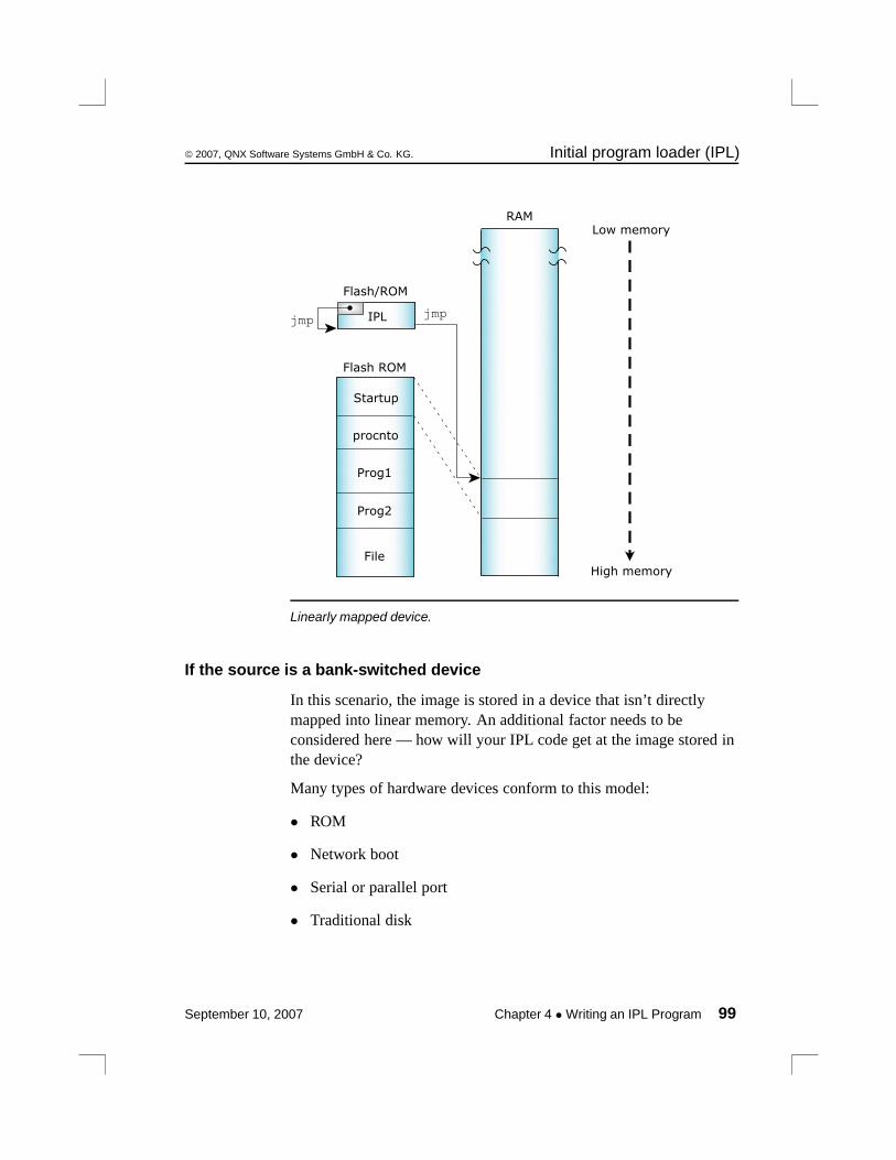
© 2007, QNX Software Systems GmbH & Co. KG. Initial program loader (IPL)
RAM
Flash ROM
Startup
procnto
Prog1
Prog2
IPLjmpjmp
Flash/ROM
File
Low memory
High memory
Linearly mapped device.
If the source is a bank-switched device
In this scenario, the image is stored in a device that isn’t directlymapped into linear memory. An additional factor needs to beconsidered here — how will your IPL code get at the image stored inthe device?
Many types of hardware devices conform to this model:
• ROM
• Network boot
• Serial or parallel port
• Traditional disk
September 10, 2007 Chapter 4 • Writing an IPL Program 99
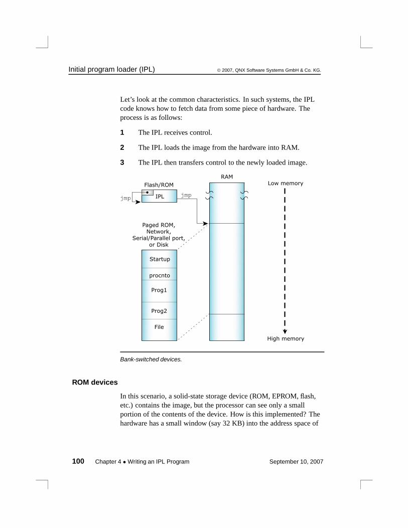
Initial program loader (IPL) © 2007, QNX Software Systems GmbH & Co. KG.
Let’s look at the common characteristics. In such systems, the IPLcode knows how to fetch data from some piece of hardware. Theprocess is as follows:
1 The IPL receives control.
2 The IPL loads the image from the hardware into RAM.
3 The IPL then transfers control to the newly loaded image.
RAM
Startup
procnto
Prog1
Prog2
File
IPLjmpjmp
Flash/ROM Low memory
High memory
Paged ROM,Network,
Serial/Parallel port,or Disk
Bank-switched devices.
ROM devices
In this scenario, a solid-state storage device (ROM, EPROM, flash,etc.) contains the image, but the processor can see only a smallportion of the contents of the device. How is this implemented? Thehardware has a small window (say 32 KB) into the address space of
100 Chapter 4 • Writing an IPL Program September 10, 2007
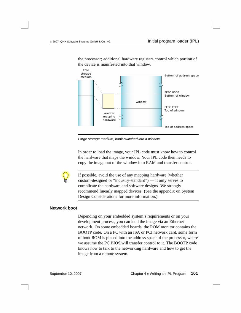
© 2007, QNX Software Systems GmbH & Co. KG. Initial program loader (IPL)
the processor; additional hardware registers control which portion ofthe device is manifested into that window.
Window
Top of address space
FFFC FFFFTop of window
FFFC 8000Bottom of window
Bottom of address space
Window
mapping
hardware
20M
storage
medium
Large storage medium, bank-switched into a window.
In order to load the image, your IPL code must know how to controlthe hardware that maps the window. Your IPL code then needs tocopy the image out of the window into RAM and transfer control.
If possible, avoid the use of any mapping hardware (whethercustom-designed or “industry-standard”) — it only serves tocomplicate the hardware and software designs. We stronglyrecommend linearly mapped devices. (See the appendix on SystemDesign Considerations for more information.)
Network boot
Depending on your embedded system’s requirements or on yourdevelopment process, you can load the image via an Ethernetnetwork. On some embedded boards, the ROM monitor contains theBOOTP code. On a PC with an ISA or PCI network card, some formof boot ROM is placed into the address space of the processor, wherewe assume the PC BIOS will transfer control to it. The BOOTP codeknows how to talk to the networking hardware and how to get theimage from a remote system.
September 10, 2007 Chapter 4 • Writing an IPL Program 101
Initial program loader (IPL) © 2007, QNX Software Systems GmbH & Co. KG.
Using a BOOTP server
To boot a Neutrino system using BOOTP, you’ll need a BOOTP ROMfor your OS client and a BOOTP server (e.g. bootpd) for your server.Since the TFTP protocol is used to move the image from the server tothe client, you’ll also need a TFTP server — this is usually providedwith a BOOTP server on most systems (Neutrino, UNIX, Windows95/98/NT.)
Serial port
A serial port on the target can be useful during development fordownloading an image or as a failsafe mechanism (e.g. if a checksumfails, you can simply reload the image via the serial port).
A serial loader can be built into the IPL code so that the code canfetch the image from an external hardware port. This generally has aminimal impact on the cost of an embedded system; in most cases, theserial port hardware can be left off for final assembly. Evaluationboards supplied by hardware chip vendors often have serial ports. Wesupply source code for an embedded serial loader for the 8250 chip.
The IPL process in this case is almost identical to the one discussedabove for the Network boot, except that the serial port is used to fetchthe image.
Traditional disk
In a traditional PC-style embedded system with a BIOS, this is thesimplest boot possible. The BIOS performs all the work for you — itfetches the image from disk, transfers it to RAM, and starts it.
On the other hand, if you don’t have a BIOS but you wish toimplement this kind of a boot, then this method involves the mostcomplicated processing discussed so far. This is because you’ll need adriver that knows how to access the disk (whether it’s a traditionalrotating-medium hard disk or a solid-state disk). Your IPL code thenneeds to look into the partition table of the device and figure outwhere the contents of the image reside. Once that determination hasbeen made, the IPL then needs to either map the image portions into a
102 Chapter 4 • Writing an IPL Program September 10, 2007
© 2007, QNX Software Systems GmbH & Co. KG. Customizing IPLs
window and transfer bytes to RAM (in the case of a solid-state disk)or fetch the data bytes from the disk hardware.
None of the above?
It’s entirely conceivable that none of the above adequately describesyour particular embedded system. In that case, the IPL code you’llwrite must still perform the same basic steps as described above —handle the reset vector, fetch the image from some medium, andtransfer control to the startup routine.
Transferring control to the startup programOnce the image has either been loaded into RAM or is available forexecution in ROM, we must transfer control to the startup code(copied from the image to RAM).
For detailed information about the different types of startup programs,see the chapter on Customizing Image Startup Programs.
Once the startup code is off and running, the work of the IPL processis done.
Customizing IPLsThis section describes in detail the steps necessary to write the IPL foran embedded system that boots from ROM or Flash.
Systems that boot from disk or over the network typically come witha BIOS or ROM monitor, which already contains a large part of theIPL within it. If your embedded system fits this category, you canprobably skip directly to the chapter on Customizing Image StartupPrograms.
Your IPL loader gets control at reset time and performs the followingmain functions:
1 Initialize hardware (via assembly-language code).
2 Download the image into RAM (e.g. via serial usingimage_download_8250()).
September 10, 2007 Chapter 4 • Writing an IPL Program 103
Customizing IPLs © 2007, QNX Software Systems GmbH & Co. KG.
3 Locate the OS image (via image_scan()).
4 Copy the startup program (via image_setup()).
5 Jump to the loaded image (via image_start()).
Initialize hardwareBasic hardware initialization is done at this time. This includesgaining access to the system RAM, which may not be addressableafter reset. The amount of initialization done here will depend onwhat was done by any code before this loader gained control. Onsome systems, the power-on-reset will point directly to this code,which will have to do everything. On other systems, this loader maybe called by an even more primitive loader, which may have alreadyperformed some of these tasks.
Note that it’s not necessary to initialize standard peripheral hardwaresuch as an IDE interface or the baud rate of serial ports. This will bedone by the OS drivers when they’re started later. Technically, youneed to initialize only enough hardware to allow control to betransferred to the startup program in the image.
The startup program is written in C and is provided in fullsource-code format. The startup code is structured in a readilycustomizable manner, providing a simple environment for performingfurther initializations, such as setting up the system page in-memorydata structure.
Loading the image into RAMThe IPL code must locate the boot image (made with the mkifsutility) and copy part or all of it into memory.
The loader uses information in the header to copy the header andstartup into RAM. The loader would be responsible for copying theentire image into RAM if the image weren’t located in linearlyaddressable memory.
104 Chapter 4 • Writing an IPL Program September 10, 2007

© 2007, QNX Software Systems GmbH & Co. KG. Customizing IPLs
Structure of the boot headerThe boot header structure struct startup_header is defined inthe include file <sys/startup.h>. It is 256 bytes in size andcontains the following members, which are examined by the IPLand/or startup code:
unsigned long signature
unsigned short version
unsigned char flags1
unsigned char flags2
unsigned short header_size
unsigned short machine
unsigned long startup_vaddr
unsigned long paddr_bias
unsigned long image_paddr
unsigned long ram_paddr
unsigned long ram_size
unsigned long startup_size
unsigned long stored_size
unsigned long imagefs_paddr
unsigned long imagefs_size
unsigned short preboot_size
unsigned short zero0
unsigned long zero [3]
unsigned long info [48]
A valid image (for bootable images) is detected by performing achecksum (via the function call checksum()) over the entire image, asfollows:
checksum (image_paddr, startup_size);checksum (image_paddr + startup_size, stored_size - startup_size);
September 10, 2007 Chapter 4 • Writing an IPL Program 105

Customizing IPLs © 2007, QNX Software Systems GmbH & Co. KG.
signature
This is the first 32 bits in the header and always contains0x00FF7EEB in native byte order. It’s used to identify the header. Ona machine that can be either big-endian or little-endian (a bi-endianmachine, e.g. MIPS), there’s typically a hardware strap that gets seton the board to specify the endianness.
version
The version of mkifs that made the image.
flags1 and flags2
The following flags are defined for flags1 (flags2 is currently notused):
STARTUP_HDR_FLAGS1_VIRTUAL
If this flag is set, the operating system is to run with theMemory Management Unit (MMU) enabled.
For this release of Neutrino, you should always specify a virtualsystem (by specifying the virtual= attribute in your buildfile, whichthen sets the STARTUP_HDR_FLAGS1_VIRTUAL flag).
STARTUP_HDR_FLAGS1_BIGENDIAN
The processor is big-endian. Processors should always examinethis flag to check that the ENDIAN is right for them.
STARTUP_HDR_FLAGS1_COMPRESS_NONE
The image isn’t compressed.
STARTUP_HDR_FLAGS1_COMPRESS_ZLIB
The image is compressed using libz (gzip).
STARTUP_HDR_FLAGS1_COMPRESS_LZO
The image is compressed with liblzo.
106 Chapter 4 • Writing an IPL Program September 10, 2007
© 2007, QNX Software Systems GmbH & Co. KG. Customizing IPLs
STARTUP_HDR_FLAGS1_COMPRESS_UCL
The image is compressed with libucl. This is the formatchosen when using the [+compress] attribute in the mkifsbuild script.
Currently, the startup-* programs are built to understand only theUCL compression method. By twiddling the SUPPORT_CMP_*macro definitions in startup/lib/uncompress.c, you can changeto one of the other supported compression methods.
The STARTUP_HDR_FLAGS1_COMPRESS_* constants aren’t reallyflags because they may set more than one bit; they’re used as anenumeration of the types of compression.
Note that both flag flags1 and flags2 are single-byte; this ensures thatthey’re endian-neutral.
header_size
The size of the startup header (sizeof (struct
startup_header)).
machine
Machine type, from <sys/elf.h>.
startup_vaddr
Virtual address to transfer to after IPL is done.
paddr_bias
Value to add to physical address to get a value to put into a pointerand indirect through.
image_paddr
The physical address of the image. This can be in ROM or RAM,depending on the type of image; for more information, see“Relationship of struct startup_header fields,” later in thischapter.
September 10, 2007 Chapter 4 • Writing an IPL Program 107

Customizing IPLs © 2007, QNX Software Systems GmbH & Co. KG.
ram_paddr
The physical address in RAM to copy the image to. You should copystartup_size bytes worth of data.
ram_size
The number of bytes the image will occupy when it’s loaded intoRAM. This value is used by the startup code in the image and isn’tcurrently needed by the IPL code. This size may be greater thanstored_size if the image was compressed. It may also be smaller thanstored_size if the image is XIP.
startup_size
This is the size of the startup code. Copy this number of bytes fromthe start of the image into RAM. Note that the startup code is nevercompressed, so this size is true in all cases.
stored_size
This is the size of the image including the header. The stored_sizemember is also used in the copy/decompress routines for non-XIPimages.
imagefs_paddr
Set by the IPL to the physical address of the image filesystem. Usedby the startup.
imagefs_size
Size of uncompressed image filesystem.
preboot_size
Contains the number of bytes from the beginning of the loaded imageto the startup header. Note that this value will usually be zero,indicating that nothing precedes the startup portion. On an x86 with aBIOS, it will be nonzero, because there’s a small piece of code thatgets data from the BIOS in real mode and then switches into protectedmode and performs the startup.
108 Chapter 4 • Writing an IPL Program September 10, 2007
© 2007, QNX Software Systems GmbH & Co. KG. Customizing IPLs
zero and zero0
Zero filler; reserved for future expansion.
info
An array of startup_info* structures. This is the communicationsarea between the IPL and the startup code. When the IPL code detectsvarious system features (amount of memory installed, current time,information about the bus used on the system, etc.), it stores thatinformation into the info array so that the startup code can fetch itlater. This saves the startup code from performing the same detectionlogic again.
Note that the info is declared as an array of longs — this is purely toallocate the storage space. In reality, the info storage area contains aset of structures, each beginning with this header:
struct startup_info_hdr {unsigned short type;unsigned short size;
};
The type member is selected from the following list:
STARTUP_INFO_SKIP
Ignore this field. If the corresponding size member is 0, itmeans that this is the end of the info list.
STARTUP_INFO_MEM
A startup_info_mem or startup_info_mem_extendedstructure is present.
STARTUP_INFO_DISK
A startup_info_disk structure is present.
STARTUP_INFO_TIME
A startup_info_time structure is present.
STARTUP_INFO_BOX
A startup_info_box structure is present.
September 10, 2007 Chapter 4 • Writing an IPL Program 109
Customizing IPLs © 2007, QNX Software Systems GmbH & Co. KG.
Note that the struct startup_info_hdr header (containing thetype and size members) is encapsulated within each of the abovementioned struct startup_info* structures as the first element.
Let’s look at the individual structures.
struct startup_info_skip
Contains only the header as the member hdr.
struct startup_info_mem and startup_info_mem_extended
These structures contain an address and size pair defining a chunk ofmemory that should be added to procnto’s free memory pool.
The startup_info_mem structure is defined as follows:
struct startup_info_mem {struct startup_info_hdr hdr;unsigned long addr;unsigned long size;
};
The addr and size fields are 32 bits long, so memory is limited to 4GB. For larger memory blocks, the startup_info_mem_extendedstructure is used:
struct startup_info_mem_extended {struct startup_info_mem mem;unsigned long addr_hi;unsigned long size_hi;
};
For the extended structure, determine the address and size from theaddr_hi and size_hi members and the encapsulatedstartup_info_mem structure as follows:
((paddr64_t) addr_hi << 32) | mem.addr((paddr64_t) size_hi << 32) | mem.size
More than one startup_info_mem orstartup_info_mem_extended structure may be present toaccommodate systems that have free memory located in variousblocks throughout the address space.
110 Chapter 4 • Writing an IPL Program September 10, 2007
© 2007, QNX Software Systems GmbH & Co. KG. Customizing IPLs
Both these structures are indentified by a type member ofSTARTUP_INFO_MEM in the startup_info_hdr structure; use thesize field in the header to tell them apart.
struct startup_info_disk
Contains the following:
struct startup_info_disk {struct startup_info_hdr hdr;unsigned char drive;unsigned char zero;unsigned short heads;unsigned short cylinders;unsigned short sectors;unsigned long blocks;
};
Contains information about any hard disks detected (on a PC with aBIOS). The members are as follows:
drive Drive number.
zero Reserved; must be zero.
heads Number of heads present.
cylinders Number of cylinders present.
sectors Number of sectors present.
blocks Total blocksize of device. Computed by the formulaheads × cylinders × sectors. Note that this assumes512 bytes per block.
struct startup_info_time
Contains the following:
struct startup_info_time {struct startup_info_hdr hdr;unsigned long time;
};
The time member contains the current time as the number of secondssince 1970 01 01 00:00:00 GMT.
September 10, 2007 Chapter 4 • Writing an IPL Program 111
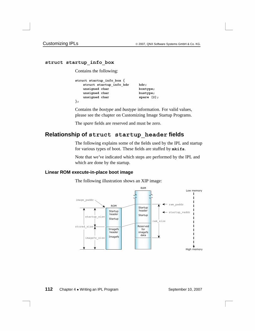
Customizing IPLs © 2007, QNX Software Systems GmbH & Co. KG.
struct startup_info_box
Contains the following:
struct startup_info_box {struct startup_info_hdr hdr;unsigned char boxtype;unsigned char bustype;unsigned char spare [2];
};
Contains the boxtype and bustype information. For valid values,please see the chapter on Customizing Image Startup Programs.
The spare fields are reserved and must be zero.
Relationship of struct startup_header fieldsThe following explains some of the fields used by the IPL and startupfor various types of boot. These fields are stuffed by mkifs.
Note that we’ve indicated which steps are performed by the IPL andwhich are done by the startup.
Linear ROM execute-in-place boot image
The following illustration shows an XIP image:
RAM
ram_size
ram_paddrROM
Startupstartup_size
stored_size
Startupheader
Imagefsheader
Imagefsimagefs_size
image_paddr
Startup
Startupheader
Reservedfor
imagefsdata
startup_vaddr
Low memory
High memory
112 Chapter 4 • Writing an IPL Program September 10, 2007
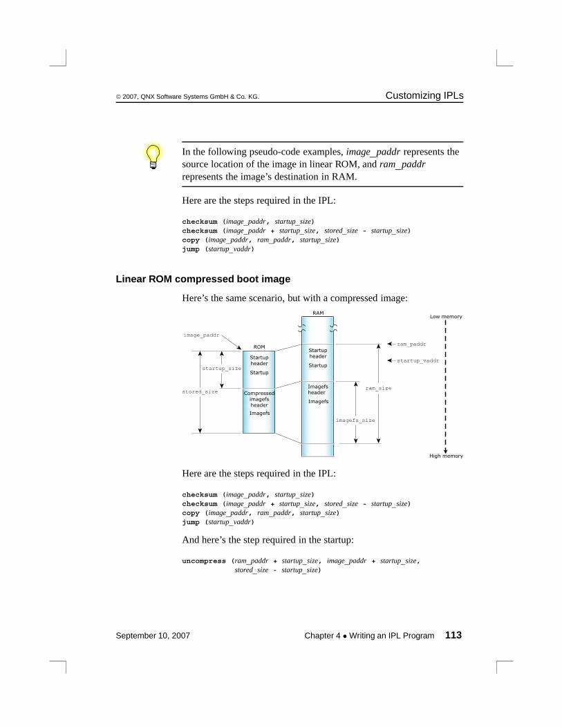
© 2007, QNX Software Systems GmbH & Co. KG. Customizing IPLs
In the following pseudo-code examples, image_paddr represents thesource location of the image in linear ROM, and ram_paddrrepresents the image’s destination in RAM.
Here are the steps required in the IPL:
checksum (image_paddr, startup_size)checksum (image_paddr + startup_size, stored_size - startup_size)copy (image_paddr, ram_paddr, startup_size)jump (startup_vaddr)
Linear ROM compressed boot image
Here’s the same scenario, but with a compressed image:RAM
ram_size
ram_paddrROM
Startupstartup_size
stored_size
Startupheader
Compressedimagefsheader
Imagefs
image_paddr
Startup
Startupheader
startup_vaddr
Imagefsheader
Imagefs
imagefs_size
Low memory
High memory
Here are the steps required in the IPL:
checksum (image_paddr, startup_size)checksum (image_paddr + startup_size, stored_size - startup_size)copy (image_paddr, ram_paddr, startup_size)jump (startup_vaddr)
And here’s the step required in the startup:
uncompress (ram_paddr + startup_size, image_paddr + startup_size,stored_size - startup_size)
September 10, 2007 Chapter 4 • Writing an IPL Program 113
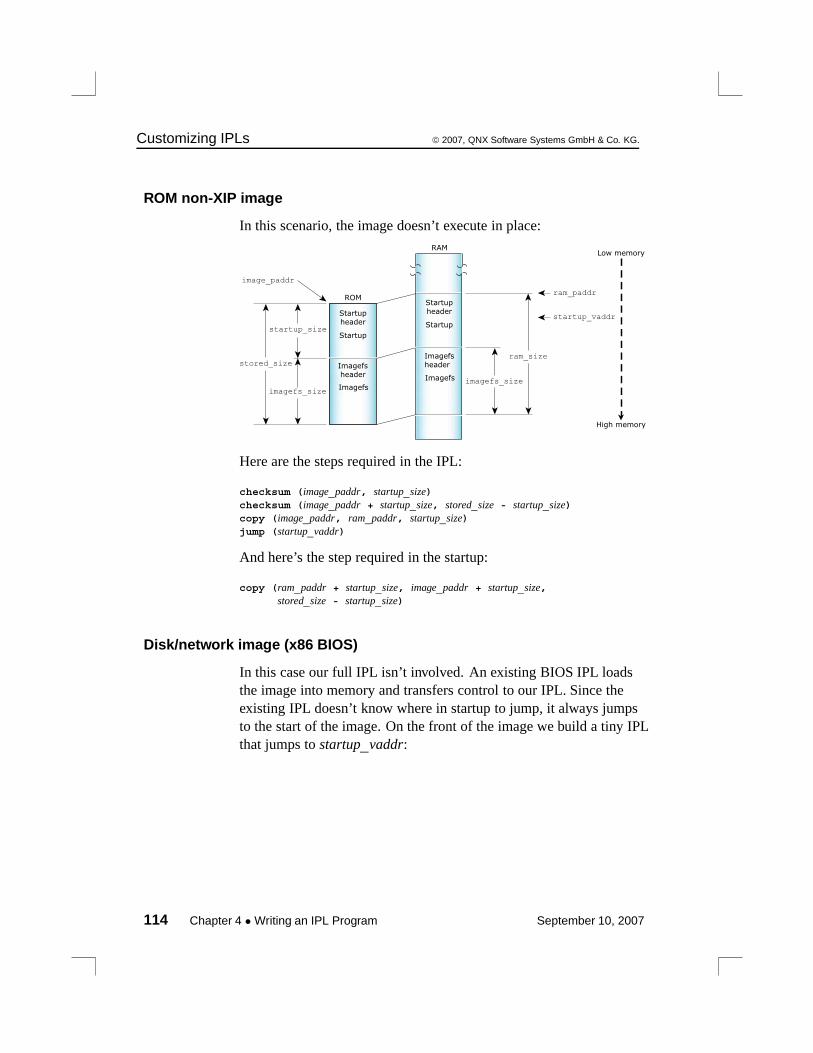
Customizing IPLs © 2007, QNX Software Systems GmbH & Co. KG.
ROM non-XIP image
In this scenario, the image doesn’t execute in place:RAM
ram_size
ram_paddrROM
Startupstartup_size
stored_size
Startupheader
Imagefsheader
Imagefs
image_paddr
Startup
Startupheader
startup_vaddr
Imagefsheader
Imagefs imagefs_size
imagefs_size
Low memory
High memory
Here are the steps required in the IPL:
checksum (image_paddr, startup_size)checksum (image_paddr + startup_size, stored_size - startup_size)copy (image_paddr, ram_paddr, startup_size)jump (startup_vaddr)
And here’s the step required in the startup:
copy (ram_paddr + startup_size, image_paddr + startup_size,stored_size - startup_size)
Disk/network image (x86 BIOS)
In this case our full IPL isn’t involved. An existing BIOS IPL loadsthe image into memory and transfers control to our IPL. Since theexisting IPL doesn’t know where in startup to jump, it always jumpsto the start of the image. On the front of the image we build a tiny IPLthat jumps to startup_vaddr:
114 Chapter 4 • Writing an IPL Program September 10, 2007
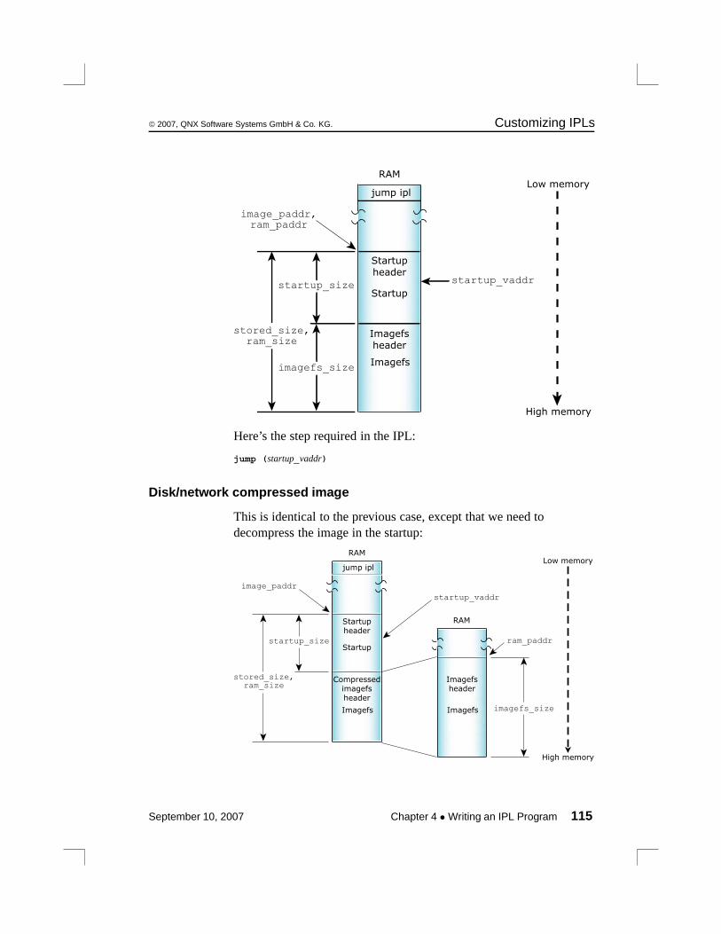
© 2007, QNX Software Systems GmbH & Co. KG. Customizing IPLs
Startupstartup_size
stored_size,ram_size
Startupheader
Imagefsheader
Imagefs
image_paddr,ram_paddr
startup_vaddr
imagefs_size
jump ipl
RAMLow memory
High memory
Here’s the step required in the IPL:
jump (startup_vaddr)
Disk/network compressed image
This is identical to the previous case, except that we need todecompress the image in the startup:
Startupstartup_size
stored_size,ram_size
Startupheader
Compressedimagefsheader
Imagefs
image_paddr
startup_vaddr
imagefs_size
jump ipl
RAM
Imagefsheader
Imagefs
RAM
ram_paddr
Low memory
High memory
September 10, 2007 Chapter 4 • Writing an IPL Program 115

Customizing IPLs © 2007, QNX Software Systems GmbH & Co. KG.
Here’s the step required in the startup:
uncompress (ram_paddr + startup_size, image_paddr + startup_size,stored_size - startup_size)
The case of a bank-switched ROM is much like a disk/network bootexcept you get to write the code that copies the image into RAMusing the following steps in the IPL:
bankcopy (image_paddr, ram_paddr, startup_size)checksum (image_paddr, startup_size)checksum (image_paddr + startup_size, stored_size - startup_size)jump (startup_vaddr)
Your next step is to go to the disk/network or disk/networkcompressed scenario above.
You’ll need to map the physical addresses and sizes intobank-switching as needed. Have fun and next time don’tbank-switch your rom! Make it linear in the address space.
IPL structureIn this section, we’ll examine the structure of the IPL source treedirectory, and also the structure of a typical IPL source file.
IPL source directory structure
The Neutrino source tree structure looks like this:
116 Chapter 4 • Writing an IPL Program September 10, 2007
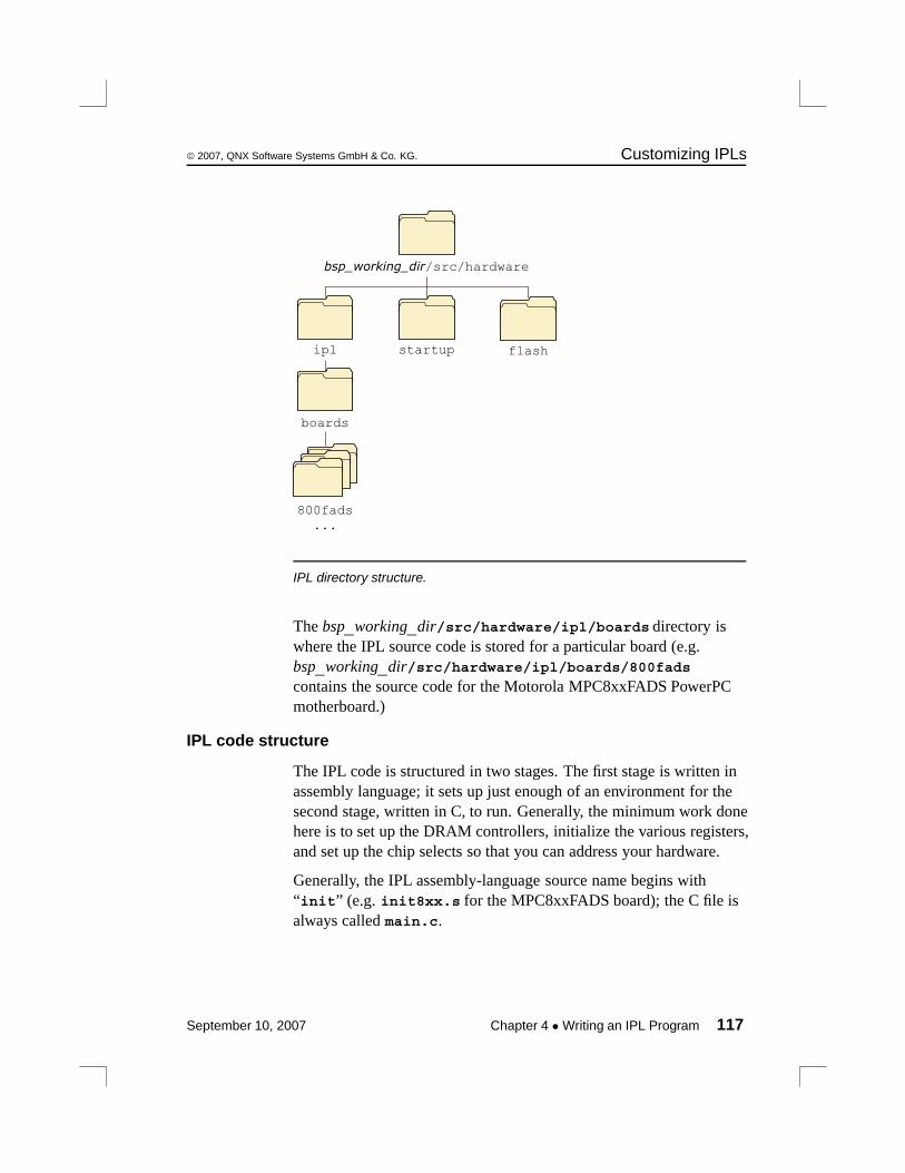
© 2007, QNX Software Systems GmbH & Co. KG. Customizing IPLs
startup flashipl
boards
800fads...
bsp_working_dir/src/hardware
IPL directory structure.
The bsp_working_dir/src/hardware/ipl/boards directory iswhere the IPL source code is stored for a particular board (e.g.bsp_working_dir/src/hardware/ipl/boards/800fadscontains the source code for the Motorola MPC8xxFADS PowerPCmotherboard.)
IPL code structure
The IPL code is structured in two stages. The first stage is written inassembly language; it sets up just enough of an environment for thesecond stage, written in C, to run. Generally, the minimum work donehere is to set up the DRAM controllers, initialize the various registers,and set up the chip selects so that you can address your hardware.
Generally, the IPL assembly-language source name begins with“init” (e.g. init8xx.s for the MPC8xxFADS board); the C file isalways called main.c.
September 10, 2007 Chapter 4 • Writing an IPL Program 117
Customizing IPLs © 2007, QNX Software Systems GmbH & Co. KG.
Once your assembly-language routine has set up the minimumamount required to transfer control to the C language portion, themain() program calls the following functions in order:
image_download_8250()
This function is responsible for getting the imagefrom wherever it may be located. If the image islocated in linear memory, this function isn’trequired (the image is already “downloaded”).
If you’re downloading the image from a custompiece of hardware, you should call your functionimage_download_hw(), where the hw part isreplaced with a descriptive name for the hardware,e.g. image_download_x25().
image_scan() This function is given a start and an end address tosearch for a boot image. If successful, it returns apointer to the start of the image. It’s possible tosearch within an address range that contains morethan one image. If there are multiple images, andone of them has a bad checksum, then the nextimage is used. If there are multiple images withgood checksums, the startup header is examined,and the one with the higher version number isused. Note that the scan will occur only betweenthe specified addresses.
image_setup() This function does the work of copying thenecessary part of the image into RAM.
image_start() This function will jump to the start of the imageloaded into RAM, which will turn control over tothe startup program.
118 Chapter 4 • Writing an IPL Program September 10, 2007
© 2007, QNX Software Systems GmbH & Co. KG. Customizing IPLs
An example
Take the main.c from the FADS8xx system:
#include "ipl.h"
unsigned int image;
intmain (void){/** Image is located at 0x2840000* Therefore, we don’t require an image_download_8250 function*/
image = image_scan (0x2840000, 0x2841000);
/** Copy startup to ram; it will do any necessary work on the image*/
image_setup (image);
/** Set up link register and jump to startup entry point*/
image_start (image);
return (0);}
In this case, we have a linearly addressable flash memory device thatcontains the image — that’s why we don’t need theimage_download_8250() function.
The next function called is image_scan(), which is given a verynarrow range of addresses to scan for the image. We give it such asmall range because we know where the image is on this system —there’s very little point searching for it elsewhere.
Then we call image_setup() with the address that we got from theimage_scan(). This copies the startup code to RAM.
Finally, we call image_start() to transfer control to the startupprogram. We don’t expect this function to return — the reason wehave the return (0); statement is to keep the C compiler happy(otherwise it would complain about “Missing return value fromfunction main”).
September 10, 2007 Chapter 4 • Writing an IPL Program 119
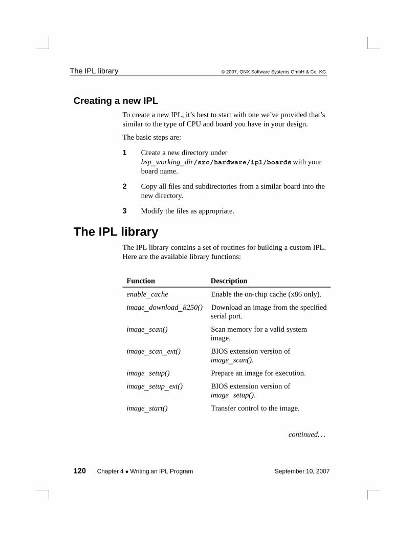
The IPL library © 2007, QNX Software Systems GmbH & Co. KG.
Creating a new IPLTo create a new IPL, it’s best to start with one we’ve provided that’ssimilar to the type of CPU and board you have in your design.
The basic steps are:
1 Create a new directory underbsp_working_dir/src/hardware/ipl/boardswith yourboard name.
2 Copy all files and subdirectories from a similar board into thenew directory.
3 Modify the files as appropriate.
The IPL libraryThe IPL library contains a set of routines for building a custom IPL.Here are the available library functions:
Function Description
enable_cache Enable the on-chip cache (x86 only).
image_download_8250() Download an image from the specifiedserial port.
image_scan() Scan memory for a valid systemimage.
image_scan_ext() BIOS extension version ofimage_scan().
image_setup() Prepare an image for execution.
image_setup_ext() BIOS extension version ofimage_setup().
image_start() Transfer control to the image.
continued. . .
120 Chapter 4 • Writing an IPL Program September 10, 2007

© 2007, QNX Software Systems GmbH & Co. KG. The IPL library
Function Description
image_start_ext() BIOS extension version ofimage_start().
int15_copy() Copy data from high (above 1 MB)memory to a buffer or to low (below 1MB) memory (x86 only).
print_byte() Print a byte to video (x86 only).
print_char() Print a character to video (x86 only).
print_long() Print a long to video (x86 only).
print_sl() Print a string, followed by a long tovideo (x86 only).
print_string() Print a string to video (x86 only).
print_var() Print a variable to video (x86 only).
print_word() Print a word to video (x86 only).
protected_mode Switch the processor to protectedmode (x86 only).
uart_hex8 Output an 8-bit hex number to theUART (x86 only).
uart_hex16 Output a 16-bit hex number to theUART (x86 only).
uart_hex32 Output a 32-bit hex number to theUART (x86 only).
uart_init Initialize the on-chip UART (x86only).
uart_put Output a single character to the UART(x86 only).
uart_string Output a NULL-terminated string tothe UART (x86 only).
continued. . .
September 10, 2007 Chapter 4 • Writing an IPL Program 121
The IPL library © 2007, QNX Software Systems GmbH & Co. KG.
Function Description
uart32_hex8 Output an 8-bit hex number to theUART (for 32-bit protected modeenvironment; x86 only).
uart32_hex16 Output a 16-bit hex number to theUART (for 32-bit protected modeenvironment; x86 only).
uart32_hex32 Output a 32-bit hex number to theUART (for 32-bit protected modeenvironment; x86 only).
uart32_init Initialize the on-chip UART (for 32-bitprotected mode environment; x86only).
uart32_put Output a single character to the UART(for 32-bit protected modeenvironment; x86 only).
uart32_string Output a NULL-terminated string tothe UART (for 32-bit protected modeenvironment; x86 only).
enable_cacheenable_cache
The enable_cache() function takes no parameters. The function ismeant to be called before the x86 processor is switched to protectedmode. Note that the function is for a non-BIOS system.
image_download_8250()unsigned int image_download_8250 (port, span, address)
Downloads an image from the specified serial port (port) to thespecified address (address) using a custom protocol. On the host side,this protocol is implemented via the utility sendnto (you may need aNULL-modem cable — the protocol uses only TX, RX, and GND).The span parameter indicates the offset from one port to the next porton the serial device.
122 Chapter 4 • Writing an IPL Program September 10, 2007

© 2007, QNX Software Systems GmbH & Co. KG. The IPL library
image_scan()unsigned long image_scan (unsigned long start, unsigned long end)
The image_scan() function scans memory for a valid system image. Itlooks on 4 KB boundaries for the image identifier bytes and then doesa checksum on the image.
The function scans between start and end. If a valid image is found,image_scan() returns the image’s address. If no valid image is found,it returns -1.
Note that image_scan() will search for all images within the givenrange, and will pick the “best” one as described above (in the “IPLcode structure” section).
image_scan_ext()unsigned long image_scan_ext (unsigned long start, unsigned long end)
This is a BIOS extension version of the image_scan() function. Theimage_scan_ext() function operates in a 16-bit real-modeenvironment.
image_setup()int image_setup (unsigned long address)
The image_setup() function prepares an image for execution. Itcopies the RAM-based startup code from ROM.
The function takes the image’s address as its parameter and alwaysreturns 0.
image_setup_ext()int image_setup_ext (unsigned long address)
This is a BIOS extension version of the image_setup() function. Theimage_setup_ext() function operates in a 16-bit real-modeenvironment and makes use of the int15_copy() function to performits tasks on the OS image.
September 10, 2007 Chapter 4 • Writing an IPL Program 123

The IPL library © 2007, QNX Software Systems GmbH & Co. KG.
image_start()int image_start (unsigned long address)
The image_start() function starts the image by jumping to thestartup_vaddr address as defined in the startup header.
The function should never return; if it fails, it returns -1.
image_start_ext()int image_start_ext (unsigned long address)
This is a BIOS extension version of the image_start() function. Theimage_start_ext() function operates in a 16-bit real-modeenvironment.
int15_copy()unsigned char int15_copy (long from, long to, long len)
The int15_copy() function is intended for an x86 system with a BIOSrunning in real mode. The function lets you copy data from highmemory (above 1 MB) to a buffer or to low memory (below 1 MB).
The int15_copy() function also allows functions such asimage_scan() and image_setup() to perform scanning and setup ofimages living in high memory.
print_byte()void print_byte (int n)
Using int10, this function displays a byte to video (x86 only).
print_char()void print_char (int c)
Using int10, this function displays a character to video (x86 only).
print_long()void print_long (unsigned long n)
Using int10, this function displays a long to video (x86 only).
124 Chapter 4 • Writing an IPL Program September 10, 2007
© 2007, QNX Software Systems GmbH & Co. KG. The IPL library
print_sl()void print_sl (char *s, unsigned long n)
Using int10, this function displays to video a string, followed by along (x86 only).
print_string()void print_string (char *msg)
Using int10, this function displays a string to video (x86 only).
print_var()void print_var (unsigned long n, int l)
Using int10, this function displays a variable to video (x86 only).
print_word()void print_word (unsigned short n)
Using int10, this function displays a word to video (x86 only).
protected_mode()
This assembly call switches the x86 processor into protected mode.The function is for non-BIOS systems.
Upon return, the DS and ES registers will be set to selectors that canaccess the entire 4 GB address space. This code is designed to becompletely position-independent.
This routine must be called with a pointer to a 16-byte area ofmemory that’s used to store the GDT. The pointer is in ds:ax.
The following selectors are defined:
8 Data selector for 0-4 GB.
16 Code selector for 0-4 GB.
uart_hex8
This assembly call outputs an 8-bit hex number to the UART. Thefunction is set up for a 16-bit real-mode environment (x86 only).
On entry:
September 10, 2007 Chapter 4 • Writing an IPL Program 125

The IPL library © 2007, QNX Software Systems GmbH & Co. KG.
DX UART base port.
AL Value to output.
uart_hex16
This assembly call outputs a 16-bit hex number to the UART. Thefunction is set up for a 16-bit real-mode environment (x86 only).
On entry:
DX UART base port.
AX Value to output.
uart_hex32
This assembly call outputs a 32-bit hex number to the UART. Thefunction is set up for a 16-bit real-mode environment (x86 only).
On entry:
DX UART base port.
EAX Value to output.
uart_init
This assembly call initializes the on-chip UART to 8 data bits, 1 stopbit, and no parity (8250 compatible). The function is set up for a16-bit real-mode environment (x86 only).
On entry:
EAX Baud rate.
EBX Input clock in Hz (normally 1843200).
ECX UART internal divisor (normally 16).
DX UART base port.
126 Chapter 4 • Writing an IPL Program September 10, 2007

© 2007, QNX Software Systems GmbH & Co. KG. The IPL library
uart_put
This assembly call outputs a single character to the UART. Thefunction is set up for a 16-bit real-mode environment (x86 only).
On entry:
AL Character to output.
DX UART base port.
uart_string
This assembly call outputs a NULL-terminated string to the UART.The function is set up for a 16-bit real-mode environment (x86 only).
On entry:
DX UART base port address, return address, string.
For example:
mov UART_BASE_PORT, %dxcall uart_string.ascii "string\r\n"...
uart32_hex8
This assembly call outputs an 8-bit hex number to the UART. Thefunction is set up for a 32-bit protected-mode environment (x86 only).
On entry:
DX UART base port.
AL Value to output.
September 10, 2007 Chapter 4 • Writing an IPL Program 127

The IPL library © 2007, QNX Software Systems GmbH & Co. KG.
uart32_hex16
This assembly call outputs a 16-bit hex number to the UART. Thefunction is set up for a 32-bit protected-mode environment (x86 only).
On entry:
DX UART base port.
AX Value to output.
uart32_hex32
This assembly call outputs a 32-bit hex number to the UART. Thefunction is set up for a 32-bit protected-mode environment (x86 only).
On entry:
DX UART base port.
EAX Value to output.
uart32_init
This assembly call initializes the on-chip UART to 8 data bits, 1 stopbit, and no parity (8250 compatible). The function is set up for a32-bit protected-mode environment (x86 only).
On entry:
EAX Baud rate.
EBX Input clock in Hz (normally 1843200).
ECX UART internal divisor (normally 16).
DX UART base port.
128 Chapter 4 • Writing an IPL Program September 10, 2007

© 2007, QNX Software Systems GmbH & Co. KG. The IPL library
uart32_put
This assembly call outputs a single character to the UART. Thefunction is set up for a 32-bit protected-mode environment (x86 only).
On entry:
AL Character to output.
DX UART base port.
uart32_string
This assembly call outputs a NULL-terminated string to the UART.The function is set up for a 32-bit protected-mode environment (x86only).
On entry:
DX UART base port address, return address, string.
For example:
mov UART_BASE_PORT, %dxcall uart_string.ascii "string\r\n"...
September 10, 2007 Chapter 4 • Writing an IPL Program 129

Chapter 5
Customizing Image StartupPrograms
In this chapter. . .Introduction 133Anatomy of a startup program 134Structure of the system page 137Callout information 174The startup library 178Writing your own kernel callout 205PPC chips support 212
September 10, 2007 Chapter 5 • Customizing Image Startup Programs 131


© 2007, QNX Software Systems GmbH & Co. KG. Introduction
IntroductionThe first program in a bootable Neutrino image is a startup programwhose purpose is to:
1 Initialize the hardware.
2 Initialize the system page.
3 Initialize callouts.
4 Load and transfer control to the next program in the image.
You can customize Neutrino for different embedded-system hardwareby changing the startup program.
Initialize hardwareYou do basic hardware initialization at this time. The amount ofinitialization done here will depend on what was done in the IPLloader.
Note that you don’t need to initialize standard peripheral hardwaresuch as an IDE interface or the baud rate of serial ports. This will bedone by the drivers that manage this hardware when they’re started.
Initialize system pageInformation about the system is collected and placed in an in-memorydata structure called the system page. This includes information suchas the processor type, bus type, and the location and size of availablesystem RAM.
The kernel as well as applications can access this information as aread-only data structure. The hardware/system-specific code tointerrogate the system for this information is confined to the startupprogram. This code doesn’t occupy any system RAM after it has run.
September 10, 2007 Chapter 5 • Customizing Image Startup Programs 133

Anatomy of a startup program © 2007, QNX Software Systems GmbH & Co. KG.
Initialize calloutsAnother key function of the startup code is that the system pagecallouts are bound in. These callouts are used by the kernel toperform various hardware- and system-specific functions that must bespecified by the systems integrator.
Anatomy of a startup programEach release of Neutrino ships with a growing number of startupprograms for many boards. To find out what boards we currentlysupport, please refer to the following sources:
• the boards directory underbsp_working_dir/src/hardware/startup.
• QNX docs (BSP docs as well as startup-* entries in UtilitiesReference).
• the Community area of our website, www.qnx.com
Each startup program is provided as a ready-to-execute binary. Fullsource and a Makefile are also available so you can customize andremake each one. The files are kept in this directory structure asillustrated:
134 Chapter 5 • Customizing Image Startup Programs September 10, 2007
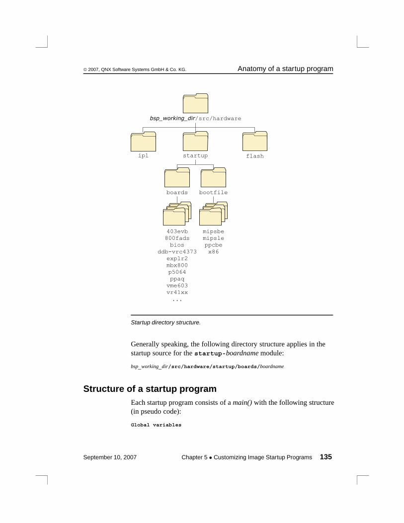
© 2007, QNX Software Systems GmbH & Co. KG. Anatomy of a startup program
flashstartupipl
boards
403evb800fadsbios
ddb-vrc4373explr2mbx800p5064ppaq
vme603vr41xx...
bootfile
mipsbemipsleppcbex86
bsp_working_dir/src/hardware
Startup directory structure.
Generally speaking, the following directory structure applies in thestartup source for the startup-boardname module:
bsp_working_dir/src/hardware/startup/boards/boardname
Structure of a startup programEach startup program consists of a main() with the following structure(in pseudo code):
Global variables
September 10, 2007 Chapter 5 • Customizing Image Startup Programs 135
Anatomy of a startup program © 2007, QNX Software Systems GmbH & Co. KG.
main(){
Call add_callout_array()
Argument parsing (Call handle_common_option())
Call init_raminfo()Remove ram used by modules in the image
if (virtual) Call init_mmu() to initialize the MMU
Call init_intrinfo()Call init_qtime()Call init_cacheattr()Call init_cpuinfo()
Set hardware machine name
Call init_system_private()
Call print_syspage() to print debugging output}
You should examine the commented source for each of the functionswithin the library to see if you need to replace a library function withone of your own.
Creating a new startup programTo create a new startup program, you should make a new directoryunder bsp_working_dir/src/hardware/startup/boards andcopy the files from one of the existing startup program directories.For example, to create something close to the Intel PXA250TMDPboard, called my_new_board, you would:
1 cd bsp_working_dir/src/hardware/startup/boards
2 mkdir my_new_board
3 cp -r pxa250tmdp/* my_new_board
4 cd my_new_board
5 make clean
136 Chapter 5 • Customizing Image Startup Programs September 10, 2007
© 2007, QNX Software Systems GmbH & Co. KG. Structure of the system page
For descriptions of all the startup functions, see “The startup library”section in this chapter.
Structure of the system pageAs mentioned earlier (see the section “Initialize system page”), one ofthe main jobs of the startup program is to initialize the system page.
The system page structure struct syspage_entry is defined inthe include file <sys/syspage.h>. The structure contains a numberof constants, references to other structures, and a union sharedbetween the various processor platforms supported by Neutrino.
It’s important to realize that there are two ways of accessing the datawithin the system page, depending on whether you’re adding data tothe system page at startup time or reading data from the system pagelater (as would be done by an application program running after thesystem has been booted). Regardless of which access method you use,the fields are the same.
Here’s the system page structure definition, taken from<sys/syspage.h>:
/** contains at least the following:*/
struct syspage_entry {uint16_t size;uint16_t total_size;uint16_t type;uint16_t num_cpu;syspage_entry_info system_private;syspage_entry_info asinfo;syspage_entry_info hwinfo;syspage_entry_info cpuinfo;syspage_entry_info cacheattr;syspage_entry_info qtime;syspage_entry_info callout;syspage_entry_info callin;syspage_entry_info typed_strings;syspage_entry_info strings;syspage_entry_info intrinfo;syspage_entry_info smp;syspage_entry_info pminfo;
September 10, 2007 Chapter 5 • Customizing Image Startup Programs 137
Structure of the system page © 2007, QNX Software Systems GmbH & Co. KG.
union {struct x86_syspage_entry x86;struct ppc_syspage_entry ppc;struct mips_syspage_entry mips;struct arm_syspage_entry arm;struct sh_syspage_entry sh;
} un;};
Note that some of the fields presented here may be initialized by thecode provided in the startup library, while some may need to beinitialized by code provided by you. The amount of initializationrequired really depends on the amount of customization that you needto perform.
Let’s look at the various fields.
sizeThe size of the system page entry. This member is set automaticallyby the library.
total_sizeThe size of the system page entry plus the referenced substructures;effectively the size of the entire system-page database. This memberis set automatically by the library and adjusted later (grown) asrequired by other library calls.
typeThis is used to indicate the CPU family for determining which unionmember in the un element to use. Can be one of:
SYSPAGE_ARM, SYSPAGE_MIPS, SYSPAGE_PPC, SYSPAGE_SH4,or SYSPAGE_X86.
The library sets this member automatically.
138 Chapter 5 • Customizing Image Startup Programs September 10, 2007
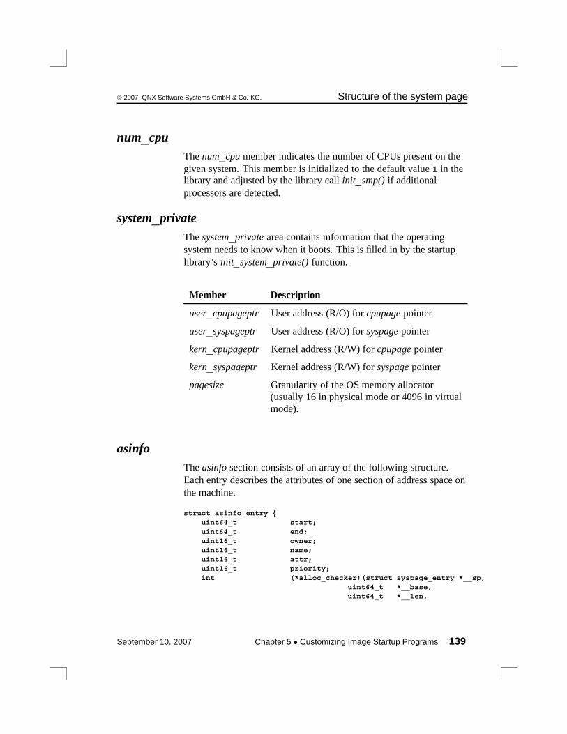
© 2007, QNX Software Systems GmbH & Co. KG. Structure of the system page
num_cpuThe num_cpu member indicates the number of CPUs present on thegiven system. This member is initialized to the default value 1 in thelibrary and adjusted by the library call init_smp() if additionalprocessors are detected.
system_privateThe system_private area contains information that the operatingsystem needs to know when it boots. This is filled in by the startuplibrary’s init_system_private() function.
Member Description
user_cpupageptr User address (R/O) for cpupage pointer
user_syspageptr User address (R/O) for syspage pointer
kern_cpupageptr Kernel address (R/W) for cpupage pointer
kern_syspageptr Kernel address (R/W) for syspage pointer
pagesize Granularity of the OS memory allocator(usually 16 in physical mode or 4096 in virtualmode).
asinfoThe asinfo section consists of an array of the following structure.Each entry describes the attributes of one section of address space onthe machine.
struct asinfo_entry {uint64_t start;uint64_t end;uint16_t owner;uint16_t name;uint16_t attr;uint16_t priority;int (*alloc_checker)(struct syspage_entry *__sp,
uint64_t *__base,uint64_t *__len,
September 10, 2007 Chapter 5 • Customizing Image Startup Programs 139

Structure of the system page © 2007, QNX Software Systems GmbH & Co. KG.
size_t __size,
size_t __align);uint32_t spare;
};
Member Description
start Gives the first physical address of the range beingdescribed.
end Gives the last physical address of the range beingdescribed. Note that this is the actual last byte, not onebeyond the end.
owner An offset from the start of the section giving the ownerof this entry (its “parent” in the tree). It’s set toAS_NULL_OFF if the entry doesn’t have an owner (it’sat the “root” of the address space tree).
name An offset from the start of the strings section of thesystem page giving the string name of this entry.
attr Contains several bits affecting the address range (seebelow).
priority Indicates the speed of the memory in the addressrange. Lower numbers mean slower memory. Themacro AS_PRIORITY_DEFAULT is defined to use adefault value for this field (currently defined as 100).
The alloc_checker isn’t currently used. When implemented, it will letyou provide finer-grain control over how the system allocates memory(e.g. making sure that ISA memory used for DMA doesn’t cross 64KB boundaries).
The attr field
The attr field can have the following bits:
140 Chapter 5 • Customizing Image Startup Programs September 10, 2007
© 2007, QNX Software Systems GmbH & Co. KG. Structure of the system page
#define AS_ATTR_READABLE 0x0001
Address range is readable.
#define AS_ATTR_WRITABLE 0x0002
Address range is writable.
#define AS_ATTR_CACHABLE 0x0004
Address range can be cached (this bit should be off if you’reusing device memory).
#define AS_ATTR_KIDS 0x0010
Indicates that there are other entries that use this one as theirowner. Note that the library turns on this bit automatically; youshouldn’t specify it when creating the section.
#define AS_ATTR_CONTINUED 0x0020
Indicates that there are multiple entries being used to describeone “logical” address range. This bit will be on in all but thelast one. Note that the library turns on this bit and uses itinternally; you shouldn’t specify it when creating the section.
Address space trees
The asinfo section contains trees describing address spaces (whereRAM, ROM, flash, etc. are located).
The general hierarchy for address spaces is:
/memory/memclass/....
Or:
/io/memclass/....
Or:
/memory/io/memclass/....
The memory or io indicates whether this is describing something inthe memory or I/O address space (the third form is used on a machine
September 10, 2007 Chapter 5 • Customizing Image Startup Programs 141
Structure of the system page © 2007, QNX Software Systems GmbH & Co. KG.
without separate in/out instructions and where everything ismemory-mapped).
The memclass is something like: ram, rom, flash, etc. Below thatwould be further classifications, allowing the process manager toprovide typed memory support.
hwinfoThe hwinfo area contains information about the hardware platform(type of bus, devices, IRQs, etc). This is filled in by the startuplibrary’s init_hwinfo() function.
This is one of the more elaborate sections of the Neutrino systempage. The hwinfo section doesn’t consist of a single structure or anarray of the same type. Instead, it consists of a sequence ofsymbolically “tagged” structures that as a whole describe thehardware installed on the board. The following types and constantsare all defined in the <hw/sysinfo.h> file.
The hwinfo section doesn’t have to describe all the hardware. Forinstance, the startup program doesn’t have to do PCI queries todiscover what’s been plugged into any slots if it doesn’t want to. It’sup to you as the startup implementor to decide how full to make thehwinfo description. As a rule, if a component is hardwired on yourboard, consider putting it into hwinfo.
Tags
Each structure (or tag) in the section starts the same way:
struct hwi_prefix {uint16_t size;uint16_t name;
};
The size field gives the size, in 4-byte quantities, of the structure(including the hwi_prefix).
The name field is an offset into the strings section of the system page,giving a zero-terminated string name for the structure. It might seem
142 Chapter 5 • Customizing Image Startup Programs September 10, 2007
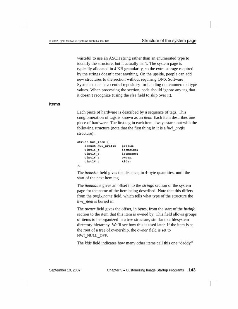
© 2007, QNX Software Systems GmbH & Co. KG. Structure of the system page
wasteful to use an ASCII string rather than an enumerated type toidentify the structure, but it actually isn’t. The system page istypically allocated in 4 KB granularity, so the extra storage requiredby the strings doesn’t cost anything. On the upside, people can addnew structures to the section without requiring QNX SoftwareSystems to act as a central repository for handing out enumerated typevalues. When processing the section, code should ignore any tag thatit doesn’t recognize (using the size field to skip over it).
Items
Each piece of hardware is described by a sequence of tags. Thisconglomeration of tags is known as an item. Each item describes onepiece of hardware. The first tag in each item always starts out with thefollowing structure (note that the first thing in it is a hwi_prefixstructure):
struct hwi_item {struct hwi_prefix prefix;uint16_t itemsize;uint16_t itemname;uint16_t owner;uint16_t kids;
};
The itemsize field gives the distance, in 4-byte quantities, until thestart of the next item tag.
The itemname gives an offset into the strings section of the systempage for the name of the item being described. Note that this differsfrom the prefix.name field, which tells what type of the structure thehwi_item is buried in.
The owner field gives the offset, in bytes, from the start of the hwinfosection to the item that this item is owned by. This field allows groupsof items to be organized in a tree structure, similar to a filesystemdirectory hierarchy. We’ll see how this is used later. If the item is atthe root of a tree of ownership, the owner field is set toHWI_NULL_OFF.
The kids field indicates how many other items call this one “daddy.”
September 10, 2007 Chapter 5 • Customizing Image Startup Programs 143

Structure of the system page © 2007, QNX Software Systems GmbH & Co. KG.
The code currently requires that the tag name of any item structuremust start with an uppercase letter; nonitem tags have to start with alowercase letter.
Device trees
The hwinfo section contains trees describing the various hardwaredevices on the board.
The general hierarchy for devices is:
/hw/bus/devclass/device
where:
hw the root of the hardware tree.
bus the bus the hardware is on (pci, eisa, etc.).
devclass the general class of the device (serial, rtc, etc.).
device the actual chip implementing the device (8250,mc146818, etc.).
Building the section
Two basic calls in the startup library are used to add things to thehwinfo section:
• hwi_alloc_tag()
• hwi_alloc_item()
void *hwi_alloc_tag(const char *name, unsigned size, unsigned align);
This call allocates a tag of size size with the tag name of name. If thestructure contains any 64-bit integer fields within it, the align fieldshould be set to 8; otherwise, it should be 4. The function returns apointer to memory that can be filled in as appropriate. Note that thehwi_prefix fields are automatically filled in by the hwi_alloc_tag()function.
144 Chapter 5 • Customizing Image Startup Programs September 10, 2007
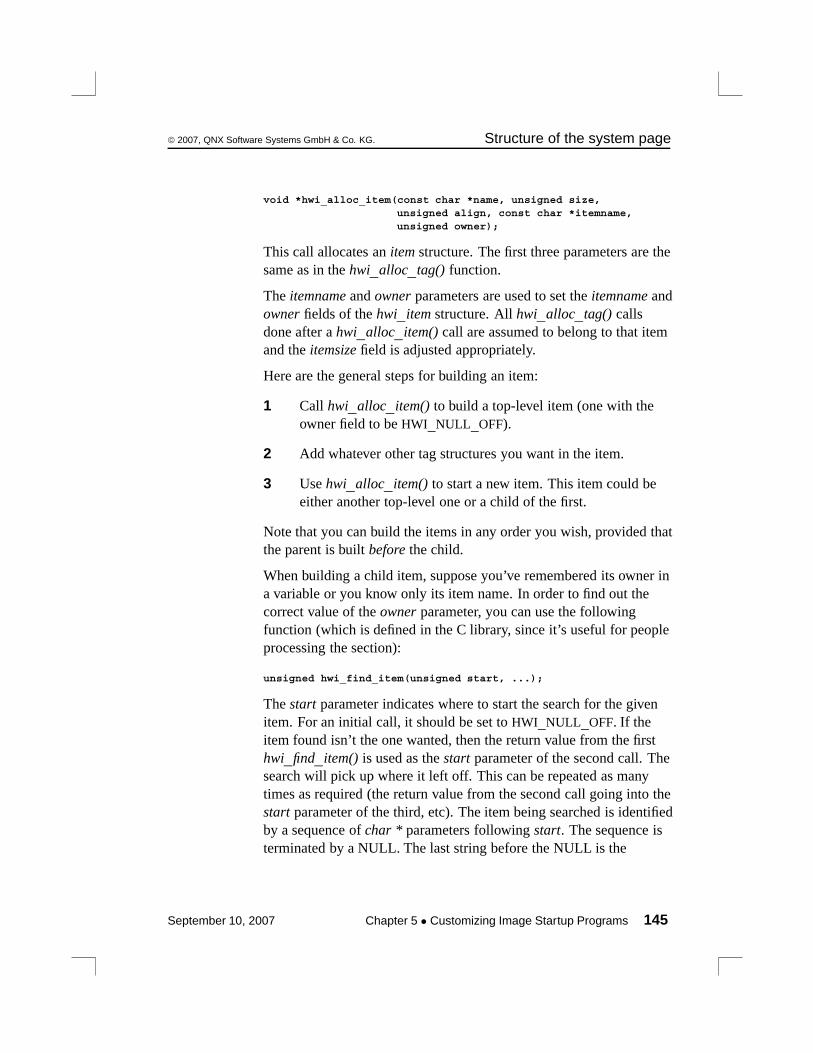
© 2007, QNX Software Systems GmbH & Co. KG. Structure of the system page
void *hwi_alloc_item(const char *name, unsigned size,unsigned align, const char *itemname,unsigned owner);
This call allocates an item structure. The first three parameters are thesame as in the hwi_alloc_tag() function.
The itemname and owner parameters are used to set the itemname andowner fields of the hwi_item structure. All hwi_alloc_tag() callsdone after a hwi_alloc_item() call are assumed to belong to that itemand the itemsize field is adjusted appropriately.
Here are the general steps for building an item:
1 Call hwi_alloc_item() to build a top-level item (one with theowner field to be HWI_NULL_OFF).
2 Add whatever other tag structures you want in the item.
3 Use hwi_alloc_item() to start a new item. This item could beeither another top-level one or a child of the first.
Note that you can build the items in any order you wish, provided thatthe parent is built before the child.
When building a child item, suppose you’ve remembered its owner ina variable or you know only its item name. In order to find out thecorrect value of the owner parameter, you can use the followingfunction (which is defined in the C library, since it’s useful for peopleprocessing the section):
unsigned hwi_find_item(unsigned start, ...);
The start parameter indicates where to start the search for the givenitem. For an initial call, it should be set to HWI_NULL_OFF. If theitem found isn’t the one wanted, then the return value from the firsthwi_find_item() is used as the start parameter of the second call. Thesearch will pick up where it left off. This can be repeated as manytimes as required (the return value from the second call going into thestart parameter of the third, etc). The item being searched is identifiedby a sequence of char * parameters following start. The sequence isterminated by a NULL. The last string before the NULL is the
September 10, 2007 Chapter 5 • Customizing Image Startup Programs 145

Structure of the system page © 2007, QNX Software Systems GmbH & Co. KG.
bottom-level itemname being searched for, the string in front of that isthe name of the item that owns the bottom-level item, etc.
For example, this call finds the first occurrence of an item called“foobar”:
item_off = hwi_find_item(HWI_NULL_OFF, "foobar", NULL);
The following call finds the first occurrence of an item called “foobar”that’s owned by “sam”:
item_off = hwi_find_item(HWI_NULL_OFF, "sam", "foobar", NULL);
If the requested item can’t be found, HWI_NULL_OFF is returned.
Other functions
The following functions are in the C library for use in processing thehwinfo section:
unsigned hwi_tag2off(void *);
Given a pointer to the start of a tag, return the offset, in bytes,from the beginning of the start of the hwinfo section.
void *hwi_off2tag(unsigned);
Given an offset, in bytes, from the start of the hwinfo section,return a pointer to the start of the tag.
unsigned hwi_find_tag(unsigned start, int curr_item,const char *tagname);
Find the tag named tagname. The start parameter works thesame as the one in hwi_find_item(). If curr_item is nonzero,the search stops at the end of the current item (whatever itemthe start parameter points into). If curr_item is zero, the searchcontinues until the end of the section. If the tag isn’t found,HWI_NULL_OFF is returned.
146 Chapter 5 • Customizing Image Startup Programs September 10, 2007

© 2007, QNX Software Systems GmbH & Co. KG. Structure of the system page
Defaults
Before main() is invoked in the startup program, the library adds someinitial entries to serve as a basis for later items.
HWI_TAG_INFO() is a macro defined in the <startup.h> headerand expands out to the three name, size, align parameters forhwi_alloc_tag() and hwi_alloc_item() based on some clever macronames.
voidhwi_default() {
hwi_tag *tag;hwi_tag *tag;
hwi_alloc_item(HWI_TAG_INFO(group), HWI_ITEM_ROOT_AS,HWI_NULL_OFF);
tag = hwi_alloc_item(HWI_TAG_INFO(group), HWI_ITEM_ROOT_HW,HWI_NULL_OFF);
hwi_alloc_item(HWI_TAG_INFO(bus), HWI_ITEM_BUS_UNKNOWN,hwi_tag2off(tag));
loc = hwi_find_item(HWI_NULL_OFF, HWI_ITEM_ROOT_AS, NULL);
tag = hwi_alloc_item(HWI_TAG_INFO(addrspace),HWI_ITEM_AS_MEMORY, loc);
tag->addrspace.base = 0;tag->addrspace.len = (uint64_t)1 << 32;#ifndef __X86__
loc = hwi_tag2off(tag);#endiftag = hwi_alloc_item(HWI_TAG_INFO(addrspace), HWI_ITEM_AS_IO,
loc);tag->addrspace.base = 0;#ifdef __X86__
tag->addrspace.len = (uint64_t)1 << 16;#else
tag->addrspace.len = (uint64_t)1 << 32;#endif
}
September 10, 2007 Chapter 5 • Customizing Image Startup Programs 147

Structure of the system page © 2007, QNX Software Systems GmbH & Co. KG.
Predefined items and tags
These are the items defined in the hw/sysinfo.h file. Note thatyou’re free to create additional items — these are just what we neededfor our own purposes. You’ll notice that all things are defined asHWI_TAG_NAME_*, HWI_TAG_ALIGN_*, and struct hwi_*. Thenames are chosen that way so that the HWI_TAG_INFO() macro instartup works properly.
Group item#define HWI_TAG_NAME_group "Group"#define HWI_TAG_ALIGN_group (sizeof(uint32_t))struct hwi_group {
struct hwi_item item;};
The Group item is used when you wish to group a number of itemstogether. It serves the same purpose as a directory in a filesystem. Forexample, the devclass level of the /hw tree would use a Group item.
Bus item#define HWI_TAG_NAME_bus "Bus"#define HWI_TAG_ALIGN_bus (sizeof(uint32))struct hwi_bus {
struct hwi_item item;};
The Bus item tells the system about a hardware bus. Item names canbe (but are not limited to):
#define HWI_ITEM_BUS_PCI "pci"#define HWI_ITEM_BUS_ISA "isa"#define HWI_ITEM_BUS_EISA "eisa"#define HWI_ITEM_BUS_MCA "mca"#define HWI_ITEM_BUS_PCMCIA "pcmcia"#define HWI_ITEM_BUS_UNKNOWN "unknown"
Device item#define HWI_TAG_NAME_device "Device"#define HWI_TAG_ALIGN_device (sizeof(uint32))struct hwi_device {
struct hwi_item item;uint32_t pnpid;
};
148 Chapter 5 • Customizing Image Startup Programs September 10, 2007
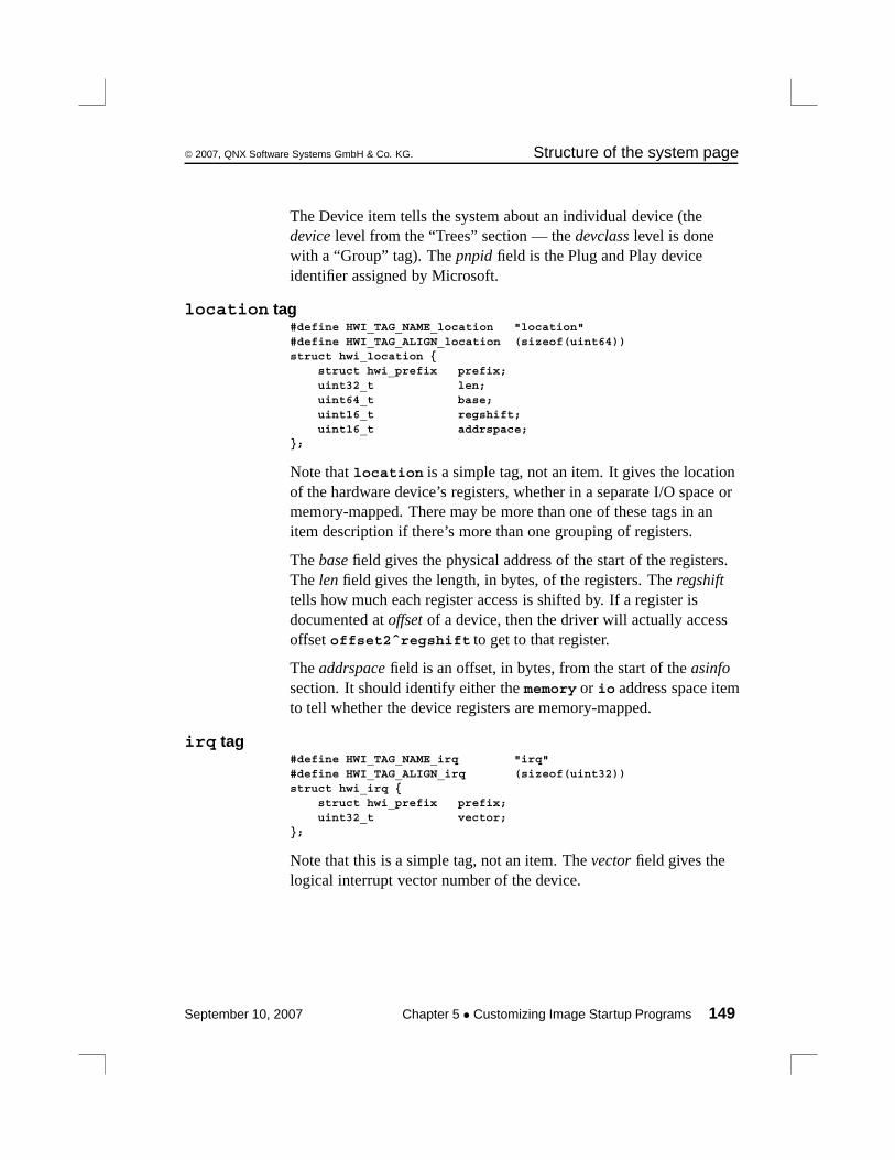
© 2007, QNX Software Systems GmbH & Co. KG. Structure of the system page
The Device item tells the system about an individual device (thedevice level from the “Trees” section — the devclass level is donewith a “Group” tag). The pnpid field is the Plug and Play deviceidentifier assigned by Microsoft.
location tag#define HWI_TAG_NAME_location "location"#define HWI_TAG_ALIGN_location (sizeof(uint64))struct hwi_location {
struct hwi_prefix prefix;uint32_t len;uint64_t base;uint16_t regshift;uint16_t addrspace;
};
Note that location is a simple tag, not an item. It gives the locationof the hardware device’s registers, whether in a separate I/O space ormemory-mapped. There may be more than one of these tags in anitem description if there’s more than one grouping of registers.
The base field gives the physical address of the start of the registers.The len field gives the length, in bytes, of the registers. The regshifttells how much each register access is shifted by. If a register isdocumented at offset of a device, then the driver will actually accessoffset offset2ˆregshift to get to that register.
The addrspace field is an offset, in bytes, from the start of the asinfosection. It should identify either the memory or io address space itemto tell whether the device registers are memory-mapped.
irq tag#define HWI_TAG_NAME_irq "irq"#define HWI_TAG_ALIGN_irq (sizeof(uint32))struct hwi_irq {
struct hwi_prefix prefix;uint32_t vector;
};
Note that this is a simple tag, not an item. The vector field gives thelogical interrupt vector number of the device.
September 10, 2007 Chapter 5 • Customizing Image Startup Programs 149
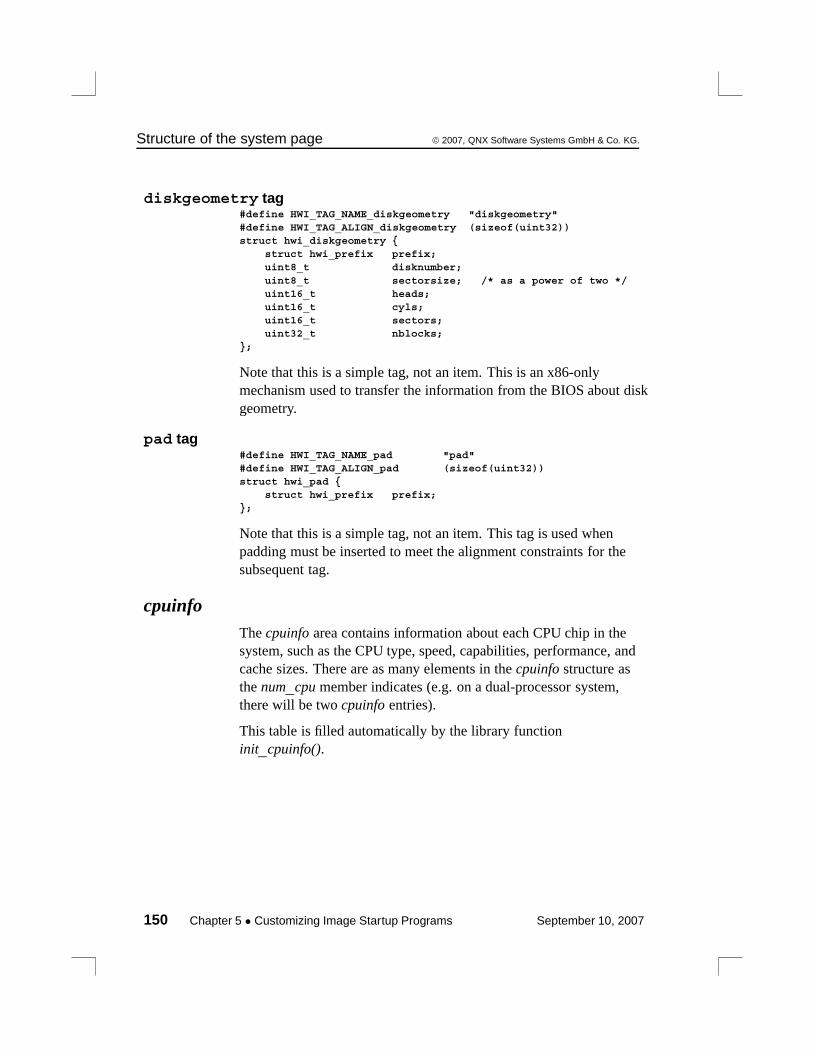
Structure of the system page © 2007, QNX Software Systems GmbH & Co. KG.
diskgeometry tag#define HWI_TAG_NAME_diskgeometry "diskgeometry"#define HWI_TAG_ALIGN_diskgeometry (sizeof(uint32))struct hwi_diskgeometry {
struct hwi_prefix prefix;uint8_t disknumber;uint8_t sectorsize; /* as a power of two */uint16_t heads;uint16_t cyls;uint16_t sectors;uint32_t nblocks;
};
Note that this is a simple tag, not an item. This is an x86-onlymechanism used to transfer the information from the BIOS about diskgeometry.
pad tag#define HWI_TAG_NAME_pad "pad"#define HWI_TAG_ALIGN_pad (sizeof(uint32))struct hwi_pad {
struct hwi_prefix prefix;};
Note that this is a simple tag, not an item. This tag is used whenpadding must be inserted to meet the alignment constraints for thesubsequent tag.
cpuinfoThe cpuinfo area contains information about each CPU chip in thesystem, such as the CPU type, speed, capabilities, performance, andcache sizes. There are as many elements in the cpuinfo structure asthe num_cpu member indicates (e.g. on a dual-processor system,there will be two cpuinfo entries).
This table is filled automatically by the library functioninit_cpuinfo().
150 Chapter 5 • Customizing Image Startup Programs September 10, 2007
© 2007, QNX Software Systems GmbH & Co. KG. Structure of the system page
Member Description
cpu This is a number that represents the type of CPU.Note that this number will vary with the CPUarchitecture. For example, on the x86 processorfamily, this number will be the processor chipnumber (e.g. 386, 586). On MIPS and PowerPC, thisis filled with the contents of the version registers.
speed Contains the MHz rating of the processor. Forexample, on a 300 MHz MIPS R4000, this numberwould be 300.
flags See below.
name Contains an index into the strings member in thesystem page structure. The character string at thespecified index contains an ASCII,NULL-terminated machine name (e.g. on a MIPSR4000 it will be the string “R4000”).
ins_cache Contains an index into the cacheattr array, describedbelow. This index points to the first definition in alist for the instruction cache.
data_cache Contains an index into the cacheattr array, describedbelow. This index points to the first definition in alist for the data cache.
The flags member contains a bitmapped indication of the capabilitiesof the CPU chip. Note that the prefix for the manifest constantindicates which CPU family it applies to (e.g. PPC_ indicates thisconstant is for use by the PowerPC family of processors). In the caseof no prefix, it indicates that it’s generic to any CPU.
Here are the constants and their defined meanings:
September 10, 2007 Chapter 5 • Customizing Image Startup Programs 151

Structure of the system page © 2007, QNX Software Systems GmbH & Co. KG.
This constant: Means that theCPU has orsupports:
CPU_FLAG_FPU Floating Point Unit(FPU).
CPU_FLAG_MMU MemoryManagement Unit(MMU), and theMMU is enabled(i.e. the CPU iscurrently in virtualaddressing mode).
X86_CPU_CPUID CPUID instruction.
X86_CPU_RDTSC RDTSC instruction.
X86_CPU_INVLPG INVLPG instruction.
X86_CPU_WP WP bit in the CR0register.
X86_CPU_BSWAP BSWAP instruction.
X86_CPU_MMX MMX instructions.
X86_CPU_CMOV CMOVxx instructions.
X86_CPU_PSE Page sizeextensions.
X86_CPU_PGE TLB (TranslationLookaside Buffer)global mappings.
X86_CPU_MTRR MTRR (MemoryType RangeRegister) registers.
continued. . .
152 Chapter 5 • Customizing Image Startup Programs September 10, 2007

© 2007, QNX Software Systems GmbH & Co. KG. Structure of the system page
This constant: Means that theCPU has orsupports:
X86_CPU_SEP SYSENTER/SYSEXITinstructions.
X86_CPU_SIMD SIMD instructions.
X86_CPU_FXSR FXSAVE/FXRSTORinstructions.
X86_CPU_PAE Extendedaddressing.
PPC_CPU_EAR EAR (ExternalAddress Register)register.
PPC_CPU_HW_HT Hardware hashtable.
PPC_CPU_HW_POW Power management.
PPC_CPU_FPREGS Floating pointregisters.
PPC_CPU_SW_HT Software hash table.
PPC_CPU_ALTIVEC AltiVec extensions.
PPC_CPU_XAEN Extendedaddressing.
PPC_CPU_SW_TLBSYNC Sync TLBs.
PPC_CPU_TLB_SHADOW Shadow registers inTLB handler.
PPC_CPU_DCBZ_NONCOHERENT DCBZ problems.
MIPS_CPU_FLAG_PFNTOPSHIFT_MASK Construct TLBentries.
continued. . .
September 10, 2007 Chapter 5 • Customizing Image Startup Programs 153
Structure of the system page © 2007, QNX Software Systems GmbH & Co. KG.
This constant: Means that theCPU has orsupports:
MIPS_CPU_FLAG_MAX_PGSIZE_MASK Maximum numberof masks.
MIPS_CPU_FLAGS_MAX_PGSIZE_SHIFT Maximum numberof shifts.
MIPS_CPU_FLAG_L2_PAGE_CACHE_OPS L2 cache.
MIPS_CPU_FLAG_64BIT 64-bit registers.
MIPS_CPU_FLAG_128BIT 128-bit registers.
MIPS_CPU_FLAG_SUPERVISOR Supervisor mode.
MIPS_CPU_FLAG_NO_WIRED No wired register.
MIPS_CPU_FLAG_NO_COUNT No count register.
syspage_entry cacheattrThe cacheattr area contains information about the configuration of theon-chip and off-chip cache system. It also contains the control()callout used for cache control operations. This entry is filled by thelibrary routines init_cpuinfo() and init_cacheattr().
Note that init_cpuinfo() deals with caches implemented on the CPUitself; init_cacheattr() handles board-level caches.
Each entry in the cacheattr area consists of the following:
Member Description
next index to next lower level entry
line_size size of cache line in bytes
num_lines number of cache lines
continued. . .
154 Chapter 5 • Customizing Image Startup Programs September 10, 2007
© 2007, QNX Software Systems GmbH & Co. KG. Structure of the system page
Member Description
flags See below
control callout supplied by startup code (see below).
The total number of bytes described by a particular cacheattr entry isdefined by line_size × num_lines.
The flags parameter is a bitmapped variable consisting of thefollowing:
This constant: Means that the cache:
CACHE_FLAG_INSTR Holds instructions.
CACHE_FLAG_DATA Holds data.
CACHE_FLAG_UNIFIED Holds both instructions anddata.
CACHE_FLAG_SHARED Is shared between multipleprocessors in an SMP system.
CACHE_FLAG_SNOOPED Implements a bus-snoopingprotocol.
CACHE_FLAG_VIRTUAL Is virtually tagged.
CACHE_FLAG_WRITEBACK Does write-back, notwrite-through.
CACHE_FLAG_CTRL_PHYS Takes physical addresses viaits control() function.
continued. . .
September 10, 2007 Chapter 5 • Customizing Image Startup Programs 155

Structure of the system page © 2007, QNX Software Systems GmbH & Co. KG.
This constant: Means that the cache:
CACHE_FLAG_SUBSET Obeys the subset property.This means that one cachelevel caches something fromanother level as well. As yougo up each cache level, ifsomething is in a particularlevel, it will also be in all thelower-level caches as well.This impacts the flushingoperations of the cache in thata “subsetted” level can beeffectively “ignored” by thecontrol() function, since itknows that the operation willbe performed on thelower-level cache.
CACHE_FLAG_NONCOHERENT Is noncoherent on SMP.
CACHE_FLAG_NONISA Doesn’t obey ISA cacheinstructions.
The cacheattr entries are organized in a linked list, with the nextmember indicating the index of the next lower cache entry. This wasdone because some architectures will have separate instruction anddata caches at one level, but a unified cache at another level. Thislinking allows the system page to efficiently contain the information.Note that the entry into the cacheattr tables is done through thecpuinfo’s ins_cache and data_cache. Since the cpuinfo is an arrayindexed by the CPU number for SMP systems, it’s possible toconstruct a description of caches for CPUs with different cachearchitectures. Here’s a diagram showing a two-processor system, withseparate L1 instruction and data caches as well as a unified L2 cache:
156 Chapter 5 • Customizing Image Startup Programs September 10, 2007

© 2007, QNX Software Systems GmbH & Co. KG. Structure of the system page
L1instruction
cache
Memory
L1datacache
L2 unified
L1instruction
cache
L1datacache
L2 unified
CPU 1 CPU 2
Two-processor system with separate L1 instruction and data caches.
Given the above memory layout, here’s what the cpuinfo andcacheattr fields will look like:
/** CPUINFO*/
cpuinfo [0].ins_cache = 0;cpuinfo [0].data_cache = 1;
cpuinfo [1].ins_cache = 0;cpuinfo [1].data_cache = 1;
/** CACHEATTR*/
cacheattr [0].next = 2;cacheattr [0].linesize = linesize;cacheattr [0].numlines = numlines;cacheattr [0].flags = CACHE_FLAG_INSTR;
cacheattr [1].next = 2;cacheattr [1].linesize = linesize;cacheattr [1].numlines = numlines;
September 10, 2007 Chapter 5 • Customizing Image Startup Programs 157

Structure of the system page © 2007, QNX Software Systems GmbH & Co. KG.
cacheattr [1].flags = CACHE_FLAG_DATA;
cacheattr [2].next = CACHE_LIST_END;cacheattr [2].linesize = linesize;cacheattr [2].numlines = numlines;cacheattr [2].flags = CACHE_FLAG_UNIFIED;
Note that the actual values chosen for linesize and numlines will, ofcourse, depend on the actual configuration of the caches present onthe system.
syspage_entry qtimeThe qtime area contains information about the timebase present on thesystem, as well as other time-related information. The library routineinit_qtime() fills these data structures.
Member Description
intr Contains the interrupt vector that the clock chipuses to interrupt the processor.
boot_time Seconds since Jan 1 1970 00:00:00 GMT whenthe system was booted.
nsec This 64-bit field holds the number ofnanoseconds since the system was booted.
nsec_tod_adjust When added to the nsec field, this field givesthe number of nanoseconds from the start of theepoch (1970).
nsec_inc Number of nanoseconds deemed to haveelapsed each time the clock triggers aninterrupt.
adjust Set to zero at startup — contains any currenttimebase adjustment runtime parameters (asspecified by the kernel call ClockAdjust()).
continued. . .
158 Chapter 5 • Customizing Image Startup Programs September 10, 2007
© 2007, QNX Software Systems GmbH & Co. KG. Structure of the system page
Member Description
timer_rate Used in conjunction with timer_scale (seebelow).
timer_scale See below.
timer_load Timer chip divisor value. The startup programleaves this zero. The kernel sets it based on thelast ClockPeriod() and timer_rate/timer_scalevalues to a number, which is then put into thetimer chip by thetimer_load/timer_reload kernel callouts.
cycles_per_sec For ClockCycles().
epoch Currently set to 1970, but not used.
flags Indicates when timer hardware is specific toCPU0.
The nsec field is always monotonically increasing and is neveraffected by setting the current time of day via ClockTime() orClockAdjust(). Since both nsec and nsec_tod_adjust are modified inthe kernel’s timer interrupt handler and are too big to load in anatomic read operation, to inspect them you must either:
• disable interrupts
or:
• get the value(s) twice and make sure that they haven’t changedbetween the first and second read.
The parameters timer_rate and timer_scale relate to the externalcounter chip’s input frequency, in Hz, as follows:
1
timer_scaletimer_rate x 10
September 10, 2007 Chapter 5 • Customizing Image Startup Programs 159
Structure of the system page © 2007, QNX Software Systems GmbH & Co. KG.
Yes, this does imply that timer_scale is a negative number. The goalwhen expressing the relationship is to make timer_rate as large aspossible in order to maximize the number of significant digitsavailable during calculations.
For example, on an x86 PC with standard hardware, the values wouldbe 838095345UL for the timer_rate and -15 for the timer_scale.This indicates that the timer value is specified in femtoseconds (the-15 means “ten to the negative fifteen”); the actual value is838,095,345 femtoseconds (approximately 838 nanoseconds).
If you need to change the number of nsecs that the OS adds to thetime when a tick fires, you can manually adjust the nsec_inc value inSYSPAGE_ENTRY (qtime).
The idea is to adjust for differences between the clock interval and thereal expired time. The closer they become the less need there is forClockAdjust() calls.
What you’ll need to do is find out the physical address of the syspage.If it’s already in nsec_inc you won’t need to modify startup. If not,modify startup to put it there. Then use the mmap_device_memory()function to make the physical address of the syspage writable. That is,get the offset to the read-only page, and map a new block of memoryto the address.
You could give ClockAdjust() a value of 0 for the number of ticks, toindicate that you want to make this adjustment “permanent”. If youdon’t want to do that, you can give the ClockAdjust() function themaximum possible value for tick_count.
When you call and modify nsec_inc, you overwrite the ClockPeriod()function. The timer_rate and timer_scale fields are used as the inputfrequency to the clock hardware. The code uses these fields and therequested tick rate to calculate the number of input frequency clocksto count before generating an interrupt. The number of inputfrequency clocks that are counted, combined with timer_rate andtimer_scale provides the nsec_inc value. For example:timer_load = requested_ticksize / (timer_rate ** timer_scale)nsec_inc = timer_load * (timer_rate ** timer_scale)
160 Chapter 5 • Customizing Image Startup Programs September 10, 2007
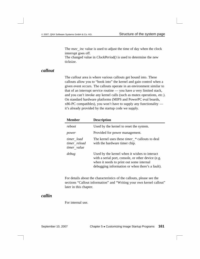
© 2007, QNX Software Systems GmbH & Co. KG. Structure of the system page
The nsec_inc value is used to adjust the time of day when the clockinterrupt goes off.The changed value in ClockPeriod() is used to determine the newticksize.
calloutThe callout area is where various callouts get bound into. Thesecallouts allow you to “hook into” the kernel and gain control when agiven event occurs. The callouts operate in an environment similar tothat of an interrupt service routine — you have a very limited stack,and you can’t invoke any kernel calls (such as mutex operations, etc.).On standard hardware platforms (MIPS and PowerPC eval boards,x86-PC compatibles), you won’t have to supply any functionality —it’s already provided by the startup code we supply.
Member Description
reboot Used by the kernel to reset the system.
power Provided for power management.
timer_loadtimer_reloadtimer_value
The kernel uses these timer_* callouts to dealwith the hardware timer chip.
debug Used by the kernel when it wishes to interactwith a serial port, console, or other device (e.g.when it needs to print out some internaldebugging information or when there’s a fault).
For details about the characteristics of the callouts, please see thesections “Callout information” and “Writing your own kernel callout”later in this chapter.
callinFor internal use.
September 10, 2007 Chapter 5 • Customizing Image Startup Programs 161
Structure of the system page © 2007, QNX Software Systems GmbH & Co. KG.
typed_stringsThe typed_strings area consists of several entries, each of which is anumber and a string. The number is 4 bytes and the string isNULL-terminated as per C. The number in the entry corresponds to aparticular constant from the system include file <confname.h> (seethe C function confname() for more information).
Generally, you wouldn’t access this member yourself; the variousinit_*() library functions put things into the typed strings literal poolthemselves. But if you need to add something, you can use thefunction call add_typed_string() from the library.
stringsThis member is a literal pool used for nontyped strings. Users of thesestrings would typically specify an index into strings (for example,cpuinfo’s name member).
Generally, you wouldn’t access this member yourself; the variousinit_*() library functions put things into the literal pool themselves.But if you need to add something, you can use the function calladd_string() from the library.
intrinfoThe intrinfo area is used to store information about the interruptsystem. It also contains the callouts used to manipulate the interruptcontroller hardware.
This area is automatically filled in by the library routineinit_intrinfo().
If you need to override some of the defaults provided byinit_intrinfo(), or if the function isn’t appropriate for your customenvironment, you can call add_interrupt_array() directly with a tableof the following format:
162 Chapter 5 • Customizing Image Startup Programs September 10, 2007

© 2007, QNX Software Systems GmbH & Co. KG. Structure of the system page
In all probability, you will need to modify this for non-x86 platforms.
Member Description
vector_base The base number of the logical interruptnumbers that programs will use (e.g. theinterrupt vector passed to InterruptAttach()).
num_vectors The number of vectors starting at vector_basedescribed by this entry.
cascade_vector If this interrupt entry describes a set of interruptsthat are cascaded into another interruptcontroller, then this variable contains the logicalinterrupt number that this controller cascadesinto.
cpu_intr_base The association between this set of interruptsand the CPU’s view of the source of theinterrupt (see below).
cpu_intr_stride The spacing between interrupt vector entries forinterrupt systems that do autovectoring. On anx86 platform with the standard 8259 controllersetup, this is the value 1, meaning that theinterrupt vector corresponding to the hardwareinterrupt sources is offset by 1 (e.g. interruptvector 0 goes to interrupt 0x30, interrupt vector1 goes to interrupt 0x31, and so on). On non-x86systems it’s usually 0, because those interruptsystems generally don’t do autovectoring. Avalue of 0 indicates that it’s not autovectored.
continued. . .
September 10, 2007 Chapter 5 • Customizing Image Startup Programs 163
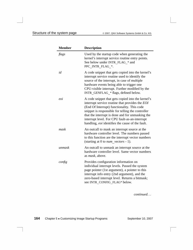
Structure of the system page © 2007, QNX Software Systems GmbH & Co. KG.
Member Description
flags Used by the startup code when generating thekernel’s interrupt service routine entry points.See below under INTR_FLAG_* andPPC_INTR_FLAG_*.
id A code snippet that gets copied into the kernel’sinterrupt service routine used to identify thesource of the interrupt, in case of multiplehardware events being able to trigger oneCPU-visible interrupt. Further modified by theINTR_GENFLAG_* flags, defined below.
eoi A code snippet that gets copied into the kernel’sinterrupt service routine that provides the EOI(End Of Interrupt) functionality. This codesnippet is responsible for telling the controllerthat the interrupt is done and for unmasking theinterrupt level. For CPU fault-as-an-interrupthandling, eoi identifies the cause of the fault.
mask An outcall to mask an interrupt source at thehardware controller level. The numbers passedto this function are the interrupt vector numbers(starting at 0 to num_vectors - 1).
unmask An outcall to unmask an interrupt source at thehardware controller level. Same vector numbersas mask, above.
config Provides configuration information onindividual interrupt levels. Passed the systempage pointer (1st argument), a pointer to thisinterrupt info entry (2nd argument), and thezero-based interrupt level. Returns a bitmask;see INTR_CONFIG_FLAG* below.
continued. . .
164 Chapter 5 • Customizing Image Startup Programs September 10, 2007
© 2007, QNX Software Systems GmbH & Co. KG. Structure of the system page
Member Description
patch_data Provides information about patched data. Thepatched data is passed to the patcher() routinethat gets called once for each callout in astartup_intrinfo() structure.
Each group of callouts (i.e. id, eoi, mask, unmask) for each level ofinterrupt controller deals with a set of interrupt vectors that start at 0(zero-based). Set the callouts for each level of interruptionaccordingly.
Interrupt vector numbers are passed without offset to the calloutroutines. The association between the zero-based interrupt vectors thecallouts use and the system-wide interrupt vectors is configuredwithin the startup-intrinfo structures. These structures are found in theinit_intrinfo() routine of startup.
The cpu_intr_base member
The interpretation of the cpu_intr_base member varies with theprocessor:
Processor Interpretation
x86 The IDT (Interrupt Descriptor Table) entry,typically 0x30.
PPC The offset from the beginning of the exceptiontable where execution begins when an externalinterrupt occurs. A sample value is 0x0140,calculated by 0x0500 ÷ 4.
continued. . .
September 10, 2007 Chapter 5 • Customizing Image Startup Programs 165
Structure of the system page © 2007, QNX Software Systems GmbH & Co. KG.
Processor Interpretation
PPC/BE Interrupts no longer start at fixed locations in lowmemory. Instead there’s a set of IVOR (InterruptVector Offset Register) registers. Each exceptionclass has a different IVOR. When you specify theinterrupt layout to startup, you’ll need to identifythe particular IVOR register the processor will usewhen the interrupt occurs. For example,PPCBKE_SPR_IVOR4 is used for normal externalinterrupts; PPCBKE_SPR_IVOR10 is used fordecrementer interrupts. Seestartup/boards/440rb/init_intrinfo.cfor an example of what to do on bookE CPUs.
PPC/Non-BE —
MIPS The value in the “cause” register when an externalinterrupt occurs. A sample value is 0.
ARM This value should be 0, since all ARM interruptsare handled via the IRQ exception.
SH The offset from the beginning of the exceptiontable where execution starts when an interruptoccurs. For example, for 7750, the value is 0x600.
The flags member
The flags member takes two sets of flags. The first set deals with thecharacteristics of the interrupts:
INTR_FLAG_NMI
Indicates that this is a NonMaskable Interrupt (NMI). An NMIis an interrupt which can’t be disabled by clearing the CPU’sinterrupt enable flag, unlike most normal interrupts.NonMaskable interrupts are typically used to signal events thatrequire immediate action, such as a parity error, a hardwarefailure, or imminent loss of power. The address for the handler’s
166 Chapter 5 • Customizing Image Startup Programs September 10, 2007
© 2007, QNX Software Systems GmbH & Co. KG. Structure of the system page
NMI is stored in the BIOS’s Interrupt Vector table at position02H. For this reason an NMI is often referred to as INT 02H.
The code in the kernel needs to differentiate between normalinterrupts and NMIs, because with an NMI the kernel needs toknow that it can’t protect (mask) the interrupt (hence the “N” inNonMaskable Interrupt). We strongly discourage the use of theNMI vector in x86 designs; we don’t support it on any non-x86platforms.
Regular interrupts that are normally used and referred to by numberare called maskable interrupts. Unlike non maskable interrupts,maskable interrupts are those that can be masked, or ignored, to allowthe processor to complete a task.
INTR_FLAG_CASCADE_IMPLICIT_EOI
Indicates that an EOI to the primary interrupt controller is notrequired when handling a cascaded interrupt (e.g. it’s doneautomatically). Only used if this entry describes a cascadedcontroller.
INTR_FLAG_CPU_FAULT
Indicates that one or more of the vectors described by this entryis not connected to a hardware interrupt source, but rather isgenerated as a result of a CPU fault (e.g. bus fault, parity error).Note that we strongly discourage designing your hardware thisway. The implication is that a check needs to be inserted for anexception into the generated code stream; after the interrupt hasbeen identified, an EOI needs to be sent to the controller. TheEOI code burst has the additional responsibility of detectingwhat address caused the fault, retrieving the fault type, and thenpassing the fault on. The primary disadvantage of this approachis that it causes extra code to be inserted into the code path.
PPC_INTR_FLAG_400ALT
Similar to INTR_FLAG_NMI, this indicates to the codegenerator that a different kernel entry sequence is required. Thisis because the PPC400 series doesn’t have an NMI, but rather
September 10, 2007 Chapter 5 • Customizing Image Startup Programs 167

Structure of the system page © 2007, QNX Software Systems GmbH & Co. KG.
has a critical interrupt that can be masked. This interrupt showsup differently from a “regular” external interrupt, so this flagindicates this fact to the kernel.
PPC_INTR_FLAG_CI
Same as PPC_INTR_FLAG_400ALT, where CI refers to criticalinterrupt.
PPC_INTR_FLAG_SHORTVEC
Indicates that exception table doesn’t have normal 256 bytes ofmemory space between this and the next vector.
The second set of flags deals with code generation:
INTR_GENFLAG_LOAD_SYSPAGE
Before the interrupt identification or EOI code sequence isgenerated, a piece of code needs to be inserted to fetch thesystem page pointer into a register so that it’s usable within theidentification code sequence.
INTR_GENFLAG_LOAD_INTRINFO
Same as INTR_GENFLAG_LOAD_SYSPAGE, except that itloads a pointer to this structure.
INTR_GENFLAG_LOAD_INTRMASK
Used only by EOI routines for hardware that doesn’tautomatically mask at the chip level. When the EOI routine isabout to reenable interrupts, it should reenable only thoseinterrupts that are actually enabled at the user level (e.g.managed by the functions InterruptMask() andInterruptUnmask()). When this flag is set, the existing interruptmask is stored in a register for access by the EOI routine. Azero in the register indicates that the interrupt should beunmasked; a nonzero indicates it should remain masked.
INTR_GENFLAG_NOGLITCH
Used by the interrupt ID code to cause a check to be made tosee if the interrupt was due to a glitch or to a different controller.
168 Chapter 5 • Customizing Image Startup Programs September 10, 2007
© 2007, QNX Software Systems GmbH & Co. KG. Structure of the system page
If this flag is set, the check is omitted — you’re indicating thatthere’s no reason (other than the fact that the hardware actuallydid generate an interrupt) to be in the interrupt service routine.If this flag is not set, the check is made to verify that thesuspected hardware really is the source of the interrupt.
INTR_GENFLAG_LOAD_CPUNUM
Same as INTR_GENFLAG_LOAD_SYSPAGE, except that itloads a pointer to the number of the CPU this structure uses.
config return values
The config callout may return zero or more of the following flags:
INTR_CONFIG_FLAG_PREATTACH
Normally, an interrupt is masked off until a routine attaches to itvia InterruptAttach() or InterruptAttachEvent(). If CPU faultindications are routed through to a hardware interrupt (notrecommended!), the interrupt would, by default, be disabled.Setting this flag causes a “dummy” connection to be made tothis source, causing this level to become unmasked.
INTR_CONFIG_FLAG_DISALLOWED
Prevents user code from attaching to this interrupt level.Generally used with INTR_CONFIG_FLAG_PREATTACH, butcould be used to prevent user code from attaching to anyinterrupt in general.
INTR_CONFIG_FLAG_IPI
Identifies the vector that’s used as the target of aninter-processor interrupt in an SMP system.
syspage_entry union unThe un union is where processor-specific system page information iskept. The purpose of the union is to serve as a demultiplexing pointfor the various CPU families. It is demultiplexed based on the valueof the type member of the system page structure.
September 10, 2007 Chapter 5 • Customizing Image Startup Programs 169

Structure of the system page © 2007, QNX Software Systems GmbH & Co. KG.
Member Processor type
x86 The x86 family SYSPAGE_X86
ppc PowerPC family SYSPAGE_PPC
mips The MIPS family SYSPAGE_MIPS
arm The ARM family SYSPAGE_ARM
sh The Hitachi SHfamily ofprocessors.
SYSPAGE_SH
un.x86This structure contains the x86-specific information. On a standardPC-compatible platform, the library routines (described later) fillthese fields:
smpinfo Contains info on how to manipulate the SMP controlhardware; filled in by the library call init_smp().
gdt Contains the Global Descriptor Table (GDT); filled inby the library.
idt Contains the Interrupt Descriptor Table (IDT); filled inby the library.
pgdir Contains pointers to the Page Directory Table(s); filledin by the library.
real_addr The virtual address corresponding to the physicaladdress range 0 through 0xFFFFF inclusive (thebottom 1 megabyte).
un.x86.smpinfo (deprecated)The members of this field are filled automatically by the functioninit_smp() within the startup library.
170 Chapter 5 • Customizing Image Startup Programs September 10, 2007
© 2007, QNX Software Systems GmbH & Co. KG. Structure of the system page
un.ppc (deprecated)This structure contains the PowerPC-specific information. On asupported evaluation platform, the library routines (described later)fill these fields. On customized hardware, you’ll have to supply theinformation.
smpinfo Contains info on how to manipulate the SMP controlhardware; filled in by the library call init_smp().
kerinfo Kernel information, filled by the library.
exceptptr Points at system exception table, filled by the library.
un.ppc.kerinfoContains information relevant to the kernel:
pretend_cpu Allows us to specify an override for the CPU IDregister so that the kernel can pretend it is a“known” CPU type. This is done because the kernel“knows” only about certain types of PPC CPUs;different variants require specialized support. Whena new variant is manufactured, the kernel will notrecognize it. By stuffing the pretend_cpu field witha CPU ID from a known CPU, the kernel willpretend that it’s running on the known variant.
init_msr Template of what bits to have on in the MSR whencreating a thread. Since the MSR changes amongthe variants in the PPC family, this allows you tospecify some additional bits that the kernel doesn’tnecessarily know about.
ppc_family Indicates what family the PPC CPU belongs to.
asid_bits Identifies what address space bits are active.
callout_ts_clear
Lets callouts know whether to turn off datatranslation to get at their hardware.
September 10, 2007 Chapter 5 • Customizing Image Startup Programs 171
Structure of the system page © 2007, QNX Software Systems GmbH & Co. KG.
un.mipsThis structure contains the MIPS-specific information:
shadow_imask
A shadow copy of the interrupt mask bits for the builtin MIPSinterrupt controller.
un.armThis structure contains the ARM-specific information:
L1_vaddr Virtual address of the MMU level 1 page table usedto map the kernel.
L1_paddr Physical address of the MMU level 1 page tableused to map the kernel.
startup_base Virtual address of a 1-1 virtual-physical mappingused to map the startup code that enables the MMU.This virtual mapping is removed when the kernel isinitialized.
startup_size Size of the mapping used for startup_base.
cpu Structure containing ARM core-specific operationsand data. Currently this contains the following:
page_flush A routine used to implementCPU-specific cache/TLB flushingwhen the memory manager unmaps orchanges the access protections to avirtual memory mapping for a page.This routine is called for each page ina range being modified by the virtualmemory manager.
page_flush_deferred
A routine used to perform anyoperations that can be deferred when
172 Chapter 5 • Customizing Image Startup Programs September 10, 2007
© 2007, QNX Software Systems GmbH & Co. KG. Structure of the system page
page_flush is called. For example onthe SA-1110 processor, an Icacheflush is deferred until all pages beingoperated on have been modified.
un.shThis structure contains the Hitachi SH-specific information:
exceptptr Points at system exception table, filled by the library.
smpThe smp area is CPU-independent and contains the followingelements:
This element Description
send_ipi Sends an interprocess interrupt (IPI) to the CPU.
start_address Get the starting address for the IPI.
pending Identify the pending interrupts for the SMP processor.
cpu Identify the SMP CPU.
pminfoThe pminfo area is a communication area between the power managerand startup/power callout.
The pminfo area contains the following elements which arecustomizable in the power manager structure and are power-managerdependent:
September 10, 2007 Chapter 5 • Customizing Image Startup Programs 173

Callout information © 2007, QNX Software Systems GmbH & Co. KG.
This element Description
wakeup_pending Notifies the power callout that a wakeup condition hasoccurred. The power manager requires write access so it canmodify this entry.
wakeup_condition Indicates to the power manager what has caused the wakeupi.e. whether it’s a power-on reset, or an interrupt fromperipherals or other devices. The value is set by the powercallout.
managed_storage This entry is an area where the power manager can store anydata it chooses. This storage is not persistent storage; it needsto be manually stored and restored by the startup and powercallout.The managed_storage element is initialized by theinit_pminfo() function call in startup and can be modified atstartup. The value passed into init_pminfo() determines thesize of the managed_storage array.
Callout informationAll the callout routines share a set of similar characteristics:
• coded in assembler
• position-independent
• no static read/write storage
Callouts are basically binding standalone pieces of code for the kernelto invoke without having to statically link them to the kernel.
The requirement for coding the callouts in assembler stems from thesecond requirement (i.e. that they must be written to beposition-independent). This is because the callouts are provided aspart of the startup code, which will get overwritten when the kernelstarts up. In order to circumvent this, the startup program will copy
174 Chapter 5 • Customizing Image Startup Programs September 10, 2007
© 2007, QNX Software Systems GmbH & Co. KG. Callout information
the callouts to a safe place — since they won’t be in the location thatthey were loaded in, they must be coded to be position-independent.
We need to qualify the last requirement (i.e. that callouts not use anystatic read/write storage). There’s a mechanism available for a givencallout to allocate a small amount of storage space within the systempage, but the callouts cannot have any static read/write storage spacedefined within themselves.
Debug interfaceThe debug interface consists of the following callouts:
• display_char()
• poll_key()
• break_detect().
These three callouts are used by the kernel when it wishes to interactwith a serial port, console, or other device (e.g. when it needs to printout some internal debugging information or when there’s a fault).Only the display_char() is required; the others are optional.
Clock/timer interfaceHere are the clock and timer interface callouts:
• timer_load()
• timer_reload()
• timer_value().
The kernel uses these callouts to deal with the hardware timer chip.
The timer_load() callout is responsible for stuffing the divisor valuepassed by the kernel into the timer/counter chip. Since the kerneldoesn’t know the characteristics of the timer chip, it’s up to thetimer_load() callout to take the passed value and validate it. Thekernel will then use the new value in any internal calculations it
September 10, 2007 Chapter 5 • Customizing Image Startup Programs 175
Callout information © 2007, QNX Software Systems GmbH & Co. KG.
performs. You can access the new value in the qtime_entry element ofthe system page as well as through the ClockPeriod() function call.
The timer_reload() callout is called after the timer chip generates aninterrupt. It’s used in two cases:
• Reloading the divisor value (because some timer hardware doesn’thave an automatic reload on the timer chip — this type ofhardware should be avoided if possible).
• Telling the kernel whether the timer chip caused the interrupt ornot (e.g. if you had multiple interrupt sources tied to the same lineused by the timer — not the ideal hardware design, but. . . ).
The timer_value() callout is used to return the value of the timerchip’s internal count as a delta from the last interrupt. This is used onprocessors that don’t have a high-precision counter built into the CPU(e.g. 80386, 80486).
Interrupt controller interfaceHere are the callouts for the interrupt controller interface:
• mask()
• unmask()
• config()
In addition, two “code stubs” are provided:
• id
• eoi
The mask() and unmask() perform masking and unmasking of aparticular interrupt vector.
The config() callout is used to ascertain the configuration of aninterrupt level.
For more information about these callouts, refer to the intrinfostructure in the system page above.
176 Chapter 5 • Customizing Image Startup Programs September 10, 2007
© 2007, QNX Software Systems GmbH & Co. KG. Callout information
Cache controller interfaceDepending on the cache controller circuitry in your system, you mayneed to provide a callout for the kernel to interface to the cachecontroller.
On the x86 architecture, the cache controller is integrated tightly withthe CPU, meaning that the kernel doesn’t have to talk to the cachecontroller. On other architectures, like the MIPS and PowerPC, thecache controllers need to be told to invalidate portions of the cachewhen certain functions are performed in the kernel.
The callout for cache control is control(). This callout gets passed:
• a set of flags (defining the operation to perform)
• the address (either in virtual or physical mode, depending on flagsin the cacheattr array in the system page)
• the number of cache lines to affect
The callout is responsible for returning the number of cache lines thatit affected — this allows the caller (the kernel) to call the control()callout repeatedly at a higher level. A return of 0 indicates that theentire cache was affected (e.g. all cache entries were invalidated).
System reset calloutThe miscellaneous callout, reboot(), gets called whenever the kernelneeds to reboot the machine.
The reboot() callout is responsible for resetting the system. Thiscallout lets developers customize the events that occur when procneeds to reboot — such as turning off a watchdog, banging the rightregisters etc. without customizing proc each time.
A “shutdown” of the binary will call sysmgr_reboot(), which willeventually trigger the reboot() callout.
September 10, 2007 Chapter 5 • Customizing Image Startup Programs 177

The startup library © 2007, QNX Software Systems GmbH & Co. KG.
Power management calloutThe power() callout gets called whenever power management needsto be activated.
The power() callout is used for power management.
The startup libraryThe startup library contains a rich set of routines consisting ofhigh-level functions that are called by your main() through to utilityfunctions for interrogating the hardware, initializing the system page,loading the next process in the image, and switching to protectedmode. Full source is provided for all these functions, allowing you tomake local copies with minor modifications in your target startupdirectory.
The following are the available library functions (in alphabeticalorder):
add_cache()int add_cache(int next,
unsigned flags,unsigned line_size,unsigned num_lines,const struct callout_rtn *rtn);
Add an entry to the cacheattr section of the system page structure.Parameters map one-to-one with the structure’s fields. The returnvalue is the array index number of the added entry. Note that if there’salready an entry that matches the one you’re trying to add, that entry’sindex is returned — nothing new is added to the section.
add_callout()void add_callout(unsigned offset,
const struct callout_rtn *callout);
Add a callout to the callout_info section of the system page. Theoffset parameter holds the offset from the start of the section (asreturned by the offsetof() macro) that the new routine’s address shouldbe placed in.
178 Chapter 5 • Customizing Image Startup Programs September 10, 2007

© 2007, QNX Software Systems GmbH & Co. KG. The startup library
add_callout_array()void add_callout_array (const struct callout_slot *slots,
unsigned size)
Add the callout array specified by slots (for size bytes) into the calloutarray in the system page.
add_interrupt()struct intrinfo_entry
*add_interrupt(const struct startup_intrinfo*startup_intr);
Add a new entry to the intrinfo section. Returns a pointer to the newlyadded entry.
add_interrupt_array()void add_interrupt_array (const struct startup_intrinfo *intrs,
unsigned size)
Add the interrupt array callouts specified by intrs (for size bytes) intothe interrupt callout array in the system page.
add_ram()void add_ram(paddr_t start,
paddr_t size);
Tell the system that there’s RAM available starting at physical addressstart for size bytes.
add_string()unsigned add_string (const char *name)
Add the string specified by name into the string literal pool in thesystem page and return the index.
add_typed_string()unsigned add_typed_string (int type_index,
const char *name)
Add the typed string specified by name (of type type_index) into thetyped string literal pool in the system page and return the index.
September 10, 2007 Chapter 5 • Customizing Image Startup Programs 179
The startup library © 2007, QNX Software Systems GmbH & Co. KG.
alloc_qtime()struct qtime_entry *alloc_qtime(void);
Allocate space in the system page for the qtime section and fill in theepoch, boot_time, and nsec_tod_adjust fields. Returns a pointer tothe newly allocated structure so that user code can fill in the otherfields.
alloc_ram()paddr_t alloc_ram (paddr_t addr,
paddr_t size,paddr_t align)
Allocate memory from the free memory pool initialized by the call toinit_raminfo(). The RAM is not cleared.
as_add()unsigned as_add(paddr_t start,
paddr_t end,unsigned attr,const char *name,unsigned owner);
Add an entry to the asinfo section of the system page. Parametersmap one-to-one with field names. Returns the offset from the start ofthe section for the new entry.
as_add_containing()unsigned as_add_containing(paddr_t start,
paddr_t end,unsigned attr,const char *name,const char *container);
Add new entries to the asinfo section, with the owner field set towhatever entries are named by the string pointed to by container. Thisfunction can add multiple entries because the start and end values areconstrained to stay within the start and end of the containing entry(e.g. they get clipped such that they don’t go outside the parent). Ifmore than one entry is added, the AS_ATTR_CONTINUED bit will beturned on in all but the last. Returns the offset from the start of thesection for the first entry added.
180 Chapter 5 • Customizing Image Startup Programs September 10, 2007
© 2007, QNX Software Systems GmbH & Co. KG. The startup library
as_default()unsigned as_default(void);
Add the default memory and io entries to the asinfo section of thesystem page.
as_find()unsigned as_find(unsigned start, ...);
The start parameter indicates where to start the search for the givenitem. For an initial call, it should be set to AS_NULL_OFF. If the itemfound isn’t the one wanted, then the return value from the firstas_find_item() is used as the start parameter of the second call. Thesearch will pick up where it left off. This can be repeated as manytimes as required (the return value from the second call going into thestart parameter of the third, etc). The item being searched is identifiedby a sequence of char * parameters following start. The sequence isterminated by a NULL. The last string before the NULL is thebottom-level itemname being searched for, the string in front of that isthe name of the item that owns the bottom-level item, etc.
For example, this call finds the first occurrence of an item called“foobar”:
item_off = as_find_item(AS_NULL_OFF, "foobar", NULL);
The following call finds the first occurrence of an item called “foobar”that’s owned by “sam”:
item_off = as_find_item(AS_NULL_OFF, "sam", "foobar", NULL);
If the requested item can’t be found, AS_NULL_OFF is returned.
as_find_containing()unsigned as_find_containing(unsigned off,
paddr_t start,paddr_t end,const char *container);
Find an asinfo entry with the name pointed to by container that atleast partially covers the range given by start and end. Follows thesame rules as as_find() to know where the search starts. Returns theoffset of the matching entry or AS_NULL_OFF if none is found. (Theas_add_containing() function uses this to find what the owner fieldsshould be for the entries it’s adding.)
September 10, 2007 Chapter 5 • Customizing Image Startup Programs 181
The startup library © 2007, QNX Software Systems GmbH & Co. KG.
as_info2off()unsigned as_info2off(const struct asinfo_entry *);
Given a pointer to an asinfo entry, return the offset from the start ofthe section.
as_off2info()struct asinfo_entry *as_off2info(unsigned offset);
Given an offset from the start of the asinfo section, return a pointer tothe entry.
as_set_checker()void as_set_checker(unsigned off,
const struct callout_rtn *rtn);
Set the checker callout field of the indicated asinfo entry. If theAS_ATTR_CONTINUED bit is on in the entry, advance to the nextentry in the section and set its priority as well (seeas_add_containing() for why AS_ATTR_CONTINUED would be on).Repeat until an entry without AS_ATTR_CONTINUED is found.
as_set_priority()void as_set_priority(unsigned as_off,
unsigned priority);
Set the priority field of the indicated entry. If theAS_ATTR_CONTINUED bit is on in the entry, advance to the nextentry in the section and set its priority as well (seeas_add_containing() for why AS_ATTR_CONTINUED would be on).Repeat until an entry without AS_ATTR_CONTINUED is found.
avoid_ram()void avoid_ram( paddr32_t start,
size_t size);
Make startup avoid using the specified RAM for any of its internalallocations. Memory remains available for procnto to use. Thisfunction is useful for specifying RAM that the IPL/ROM monitorneeds to keep intact while startup runs. Because it takes only apaddr32_t, addresses can be specified in the first 4 GB. It doesn’tneed a full paddr_t because startup will never use memory above 4GB for its own storage requirements.
182 Chapter 5 • Customizing Image Startup Programs September 10, 2007

© 2007, QNX Software Systems GmbH & Co. KG. The startup library
calc_time_t()unsigned long calc_time_t(const struct tm *tm);
Given a struct tm (with values appropriate for the UTC timezone),calculate the value to be placed in the boot_time field of the qtimesection.
calloc_ram()paddr32_t calloc_ram (size_t size,
unsigned align)
Allocate memory from the free memory pool initialized by the call toinit_raminfo(). The RAM is cleared.
callout_io_map_indirect()uintptr_t callout_io_map_indirect(unsigned size,
paddr_t phys);
Same as mmap_device_io() in the C library — provide access to anI/O port on the x86 (for other systems, callout_io_map() is the sameas callout_memory_map_indirect()) at a given physical address for agiven size. The return value is for use in the CPU’s equivalent ofin/out instructions (regular moves on all but the x86). The value is foruse in any kernel callouts (i.e. they live beyond the end of the startupprogram and are maintained by the OS while running).
callout_memory_map_indirect()void *callout_memory_map_indirect(unsigned size,
paddr_t phys,unsigned prot_flags);
Same as mmap_device_memory() in the C library — provide accessto a memory-mapped device. The value is for use in any kernelcallouts (i.e. they live beyond the end of the startup program and aremaintained by the OS while running).
callout_register_data()void callout_register_data( void *rp,
void *data );
This function lets you associate a pointer to arbitrary data with acallout. This data pointer is passed to the patcher routine (see“Patching the callout code,” below.
September 10, 2007 Chapter 5 • Customizing Image Startup Programs 183
The startup library © 2007, QNX Software Systems GmbH & Co. KG.
The rp argument is a pointer to the pointer where the callout addressis stored in the system page you’re building. For example, say youhave a pointer to a system page section that you’re working on calledfoo. In the section there’s a field bar that points to a callout when thesystem page is finished. Here’s the code:
// This sets the callout in the syspage:
foo->bar = (void *)&callout_routine_name;
// This registers data to pass to the patcher when we’re// building the final version of the system page:
callout_register_data(&foo->bar, &some_interesting_data_for_patcher);
When the patcher is called to fix up the callout that’s pointed at byfoo->bar, &some_interesting_data_for_patcher is passed to it.
chip_access()void chip_access(paddr_t base,
unsigned reg_shift,unsigned mem_mapped,unsigned size);
Get access to a hardware chip at physical address base with a registershift value of reg_shift (0 if registers are one byte apart; 1 if registersare two bytes apart, etc. See devc-ser8250 for more information).
If mem_mapped is zero, the function uses startup_io_map() to getaccess; otherwise, it uses startup_memory_map(). The size parametergives the range of locations to be given access to (the value is scaledby the reg_shift parameter for the actual amount that’s mapped).After this call is made, the chip_read*() and chip_write*() functionscan access the specified device. You can have only one chip_access()in effect at any one time.
chip_done()void chip_done(void);
Terminate access to the hardware chip specified by chip_access().
184 Chapter 5 • Customizing Image Startup Programs September 10, 2007

© 2007, QNX Software Systems GmbH & Co. KG. The startup library
chip_read8()unsigned chip_read8(unsigned off);
Read one byte from the device specified by chip_access(). The offparameter is first scaled by the reg_shift value specified inchip_access() before being used.
chip_read16()unsigned chip_read16(unsigned off);
Same as chip_read8(), but for 16 bits.
chip_read32()unsigned chip_read32(unsigned off);
Same as chip_read16(), but for 32 bits.
chip_write8()void chip_write8(unsigned off,
unsigned val);
Write one byte from the device specified by chip_access(). The offparameter is first scaled by the reg_shift value specified inchip_access() before being used.
chip_write16()void chip_write16(unsigned off,
unsigned val);
Same as chip_write8(), but for 16 bits.
chip_write32()void chip_write32(unsigned off,
unsigned val);
Same as chip_write16(), but for 32 bits.
copy_memory()void copy_memory (paddr_t dst,
paddr_t src,paddr_t len)
Copy len bytes of memory from physical memory at src to dst.
September 10, 2007 Chapter 5 • Customizing Image Startup Programs 185
The startup library © 2007, QNX Software Systems GmbH & Co. KG.
del_typed_string()int del_typed_string(int type_index);
Find the string in the typed_strings section of the system pageindicated by the type type_index and remove it. Returns the offsetwhere the removed string was, or -1 if no such string was present.
falcon_init_l2_cache()void falcon_init_l2_cache(paddr_t base);
Enable the L2 cache on a board with a Falcon system controller chip.The base physical address of the Falcon controller registers are givenby base.
falcon_init_raminfo()void falcon_init_raminfo(paddr_t falcon_base);
On a system with the Falcon system controller chip located atfalcon_base, determine how much/where RAM is installed and calladd_ram() with the appropriate parameters.
falcon_system_clock()unsigned falcon_system_clock(paddr_t falcon_base);
On a system with a Falcon chipset located at physical addressfalcon_base, return the speed of the main clock input to the CPU (inHertz). This can then be used in turn to set the cpu_freq, timer_freq,and cycles_freq variables.
find_startup_info()const void *find_startup_info (const void *start,
unsigned type)
Attempt to locate the kind of information specified by type in the dataarea used by the IPL code to communicate such information. Passstart as NULL to find the first occurrence of the given type ofinformation. Pass start as the return value from a previous call inorder to get the next information of that type. Returns 0 if noinformation of that type is found starting from start.
186 Chapter 5 • Customizing Image Startup Programs September 10, 2007
© 2007, QNX Software Systems GmbH & Co. KG. The startup library
find_typed_string()int find_typed_string(int type_index);
Return the offset from the beginning of the type_strings section of thestring with the type_index type. Return -1 if no such string is present.
handle_common_option()void handle_common_option (int opt)
Take the option identified by opt (a single ASCII character) andprocess it. This function assumes that the global variable optargpoints to the argument string for the option.
Valid values for opt and their actions are:
A Reboot switch. If set, an OS crash will cause the system toreboot. If not set, an OS crash will cause the system to hang.
D Output channel specification (e.g. kprintf(), stdout, etc.).
f [cpu_freq][,[cycles_freq][,timer_freq]]
Specify CPU frequencies. All frequencies can be followed by Hfor hertz, K for kilohertz, or M for megahertz (these suffixesaren’t case-sensitive). If no suffix is given, the library assumesmegahertz if the number is less than 1000; otherwise, itassumes hertz.
If they’re specified, cpu_freq, cycles_freq, and timer_freq areused to set the corresponding variables in the startup code:
cpu_freq — the CPU clock frequency. Also sets the speedfield in the cpuinfo section of the system page.cycles_freq — the frequency at which the value returnedby ClockCycles() increments. Also sets the cycles_per_secfield in the qtime section of the system page.timer_freq — the frequency at which the timer chip inputruns. Also sets the timer_rate and timer_scale values ofthe qtime section of the system page.
K kdebug remote debug protocol channel.
September 10, 2007 Chapter 5 • Customizing Image Startup Programs 187

The startup library © 2007, QNX Software Systems GmbH & Co. KG.
M Placeholder for processing additional memory blocks. Theparsing of additional memory blocks is deferred untilinit_system_private().
N Add the hostname specified to the typed name string spaceunder the identifier _CS_HOSTNAME.
R Used for reserving memory at the bottom of the address space.
r Used for reserving memory at any address space you specify.
S Placeholder for processing debug code’s -S option.
P Specify maximum number of CPUs in an SMP system.
j Add Jtag-related options. Reserves four bytes of memory at thespecified location and copies the physical address of the systempage to this location so the hardware debugger can retrieve it.
v Increment the verbosity global flag, debug_flag.
hwi_add_device()void hwi_add_device(const char *bus,
const char *class,const char *name,unsigned pnp);
Add an hwi_device item to the hwinfo section. The bus and classparameters are used to locate where in the device tree the new deviceis placed.
hwi_add_inputclk()void hwi_add_inputclk(unsigned clk,
unsigned div);
Add an hwi_inputclk tag to the hw item currently being constructed.
hwi_add_irq()void hwi_add_irq(unsigned vector);
Add an irq tag structure to the hwinfo section. The logical vectornumber for the interrupt will be set to vector.
188 Chapter 5 • Customizing Image Startup Programs September 10, 2007

© 2007, QNX Software Systems GmbH & Co. KG. The startup library
hwi_add_location()void hwi_add_location(paddr_t base,
paddr_t len,unsigned reg_shift,unsigned addr_space);
Add a location tag structure to the hwinfo section. The fields of thestructure will be set to the given parameters.
hwi_add_nicaddr()void hwi_add_nicaddr(const uint8 *addr,
unsigned len);
Add an hwi_nicaddr tag to the hw item currently being constructed.
hwi_add_rtc()void hwi_add_rtc(const char *name,
paddr_t base,unsigned reg_shift,unsigned len,int mmap,int cent_reg);
Add an hwi_device item describing the realtime clock to the hwinfosection. The name of the device is name. The hwi_location tag itemsare given by base, reg_shift, len, and mmap. The mmap parameterindicates if the device is memory-mapped or I/O-space-mapped and isused to set the addrspace field.
If the cent_reg parameter is not -1, it’s used to add an hwi_regnametag with the offset field set to its value. This indicates the offset fromthe start of the device where the century byte is stored.
hwi_alloc_item()void *hwi_alloc_item(const char *tagname,
unsigned size,unsigned align,const char *itemname,unsigned owner);
Add an item structure to the hwinfo section.
September 10, 2007 Chapter 5 • Customizing Image Startup Programs 189

The startup library © 2007, QNX Software Systems GmbH & Co. KG.
hwi_alloc_tag()void *hwi_alloc_tag(const char *tagname,
unsigned size,unsigned align);
Add a tag structure to the hwinfo section.
hwi_find_as()unsigned hwi_find_as(paddr_t base,int mmap);
Given a physical address of base and mmap (indicating 1 formemory-mapped and 0 for I/O-space-mapped), return the offset fromthe start of the asinfo section indicating the appropriate addrspacefield value for an hwi_location tag.
hwi_find_item()unsigned hwi_find_item(unsigned start, ...);
Although the hwi_find_item() function resides in the C library (protoin <hw/sysinfo.h>), the function is still usable from startupprograms.
Search for a given item in the hwinfo section of the system page. Ifstart is HWI_NULL_OFF, the search begins at the start of the hwinfosection. If not, it starts from the item after the offset of the one passedin (this allows people to find multiple tags of the same type; it worksjust like the find_startup_info() function). The var args portion is alist of character pointers, giving item names; the list is terminatedwith a NULL. The order of the item names gives ownershipinformation. For example:
item = hwi_find_item(HWI_NULL_OFF, "foobar", NULL);
searches for an item name called “foobar.” The following:
item = hwi_find_item(HWI_NULL_OFF, "mumblyshwartz","foobar", NULL);
also searches for “foobar,” but this time it has to be owned by an itemcalled “mumblyshwartz.”
If the item can’t be found, HWI_NULL_OFF is returned; otherwise,the byte offset within the hwinfo section is returned.
190 Chapter 5 • Customizing Image Startup Programs September 10, 2007

© 2007, QNX Software Systems GmbH & Co. KG. The startup library
hwi_find_tag()unsigned hwi_find_tag(unsigned start,
int curr_item,const char *tagname);
Although the hwi_find_tag() function resides in the C library (protoin <hw/sysinfo.h>), the function is still usable from startupprograms.
Search for a given tagname in the hwinfo section of startup. The startparameter works just like in hwi_find_item(). If curr_item is nonzero,the tagname must occur within the current item. If zero, the tagnamecan occur anywhere from the starting point of the search to the end ofthe section. If the tag can’t be found, then HWI_NULL_OFF isreturned; otherwise, the byte offset within the hwinfo section isreturned.
hwi_off2tag()void *hwi_off2tag(unsigned off);
Although the hwi_off2tag() function resides in the C library (proto in<hw/sysinfo.h>), the function is still usable from startupprograms.
Given a byte offset from the start of the hwinfo section, return apointer to the hwinfo tag structure.
hwi_tag2off()unsigned hwi_tag2off(void *tag);
Although the hwi_tag2off() function resides in the C library (proto in<hw/sysinfo.h>), the function is still usable from startupprograms.
Given a pointer to the start of a hwinfo tag instruction, convert it to abyte offset from the start of the hwinfo system page section.
September 10, 2007 Chapter 5 • Customizing Image Startup Programs 191
The startup library © 2007, QNX Software Systems GmbH & Co. KG.
init_asinfo()void init_asinfo(unsigned mem);
Initialize the asinfo section of the system page. The mem parameter isthe offset of the memory entry in the section and can be used as theowner parameter value for as_add()s that are adding memory.
init_cacheattr()void init_cacheattr (void)
Initialize the cacheattr member. For all platforms, this is a do-nothingstub.
init_cpuinfo()void init_cpuinfo (void)
Initialize the members of the cpuinfo structure with information aboutthe installed CPU(s) and related capabilities. Most systems will beable to use this function directly from the library.
init_hwinfo()void init_hwinfo (void)
Initialize the appropriate variant of the hwinfo structure in the systempage.
init_intrinfo()void init_intrinfo (void)
Initialize the intrinfo structure.
x86 You would need to change this only if your hardwaredoesn’t have the standard PC-compatible dual 8259configuration.
MIPS The default library version sets up the internal MIPSinterrupt controller.
PowerPC No default version exists; you must supply one.
ARM No default version exists; you must supply one.
192 Chapter 5 • Customizing Image Startup Programs September 10, 2007
© 2007, QNX Software Systems GmbH & Co. KG. The startup library
SH The default library version sets up the SH-4 on-chipperipheral interrupt. You need to provide the externalinterrupt code.
If you’re providing your own function, make sure it initializes:
• the interrupt controller hardware as appropriate (e.g. on the x86 itshould program the two 8259 interrupt controllers)
• the intrinfo structure with the details of the interrupt controllerhardware.
This initialization of the structure is done via a call to the functionadd_interrupt_array().
init_mmu()void init_mmu (void)
Sets up the processor for virtual addressing mode by setting uppage-mapping hardware and enabling the pager.
On the x86 family, it sets up the page tables as well as specialmappings to “known” physical address ranges (e.g. sets up a virtualaddress for the physical address ranges 0 through 0xFFFFF inclusive).
The 400 and 800 series processors within the PowerPC family arestubs; the others, i.e. the 600 series and BookE processors, are not.On the MIPS, and SH families, this function is currently a stub. Onthe PowerPC family, this function may be a stub.
On the ARM family, this function simply sets up the page tables.
init_pminfo()*init_pminfo (unsigned managed_size)
Initialize the pminfo section of the system page and set the number ofelements in the managed storage array.
September 10, 2007 Chapter 5 • Customizing Image Startup Programs 193
The startup library © 2007, QNX Software Systems GmbH & Co. KG.
init_qtime()void init_qtime (void)
Initialize the qtime structure in the system page. Most systems will beable to use this function directly from the library.
This function doesn’t exist for ARM. Specific functions exist forARM processors with on-chip timers; currently, this includes onlyinit_qtime_sa1100().
init_qtime_sa1100()void init_qtime_sa1100 (void)
Initialize the qtime structure and kernel callouts in the system page touse the on-chip timer for the SA1100 and SA1110 processors.
init_raminfo()void init_raminfo (void)
Determine the location and size of available system RAM andinitialize the asinfo structure in the system page.
If you know the exact amount and location of RAM in your system,you can replace this library function with one that simply hard-codesthe values via one or more add_ram() calls.
x86 If the RAM configuration is known (e.g. set by the IPLcode, or the multi-boot IPL code gets set by the gnuutility), then the library version of init_raminfo() willcall the library routine find_startup_info() to fetch theinformation from a known location in memory. If theRAM configuration isn’t known, then a RAM scan (viax86_scanmem()) is performed looking for validmemory between locations 0 and 0xFFFFFF, inclusive.(Note that the VGA aperture that usually starts atlocation 0xB0000 is specifically ignored.)
MIPSPowerPCARMSH There’s no library default. You must supply your own
init_raminfo() function.
194 Chapter 5 • Customizing Image Startup Programs September 10, 2007
© 2007, QNX Software Systems GmbH & Co. KG. The startup library
init_smp()void init_smp (void)
Initialize the SMP functionality of the system, assuming the hardware(e.g. x86, PPC, MIPS) supports SMP.
init_syspage_memory() (deprecated)void init_syspage_memory (void *base,
unsigned size)
Initialize the system page structure’s individual member pointers topoint to the data areas for the system page substructures (e.g.typed_strings). The base parameter is a pointer to where the systempage is currently stored (it will be moved to the kernel’s address spacelater); the size indicates how big this area is. On all platforms, thisroutine shouldn’t require modification.
init_system_private()void init_system_private (void)
Find all the boot images that need to be started and fill a structurewith that information; parse any -M options used to specify memoryregions that should be added; tell Neutrino where the image filesystemis located; and finally allocate room for the actual storage of thesystem page. On all platforms, this shouldn’t require modification.
Note that this must be the last init_*() function called.
jtag_reserve_memory()void jtag_reserve_memory (unsigned long resmem_addr,
unsigned long resmem_size,uint8_t resmem_flag)
Reserve a user-specified block of memory at the location specified inresmem_addr, if the resmem_flag is set to 0.
September 10, 2007 Chapter 5 • Customizing Image Startup Programs 195

The startup library © 2007, QNX Software Systems GmbH & Co. KG.
kprintf()void kprintf (const char *fmt, ... )
Display output using the put_char() function you provide. It supportsa very limited set of printf() style formats.
mips41xx_set_clock_freqs()void mips41xx_set_clock_freqs(unsigned sysclk);
On a MIPS R41xx series chip, set the cpu_freq, timer_freq, andcycles_freq variables appropriately, given a system clock inputfrequency of sysclk.
openbios_init_raminfo()void openbios_init_raminfo(void);
On a system that contains an OpenBIOS ROM monitor, add thesystem RAM information.
pcnet_reset()void pcnet_reset(paddr_t base,
int mmap);
Ensure that a PCnet-style Ethernet controller chip at the givenphysical address (either I/O or memory-mapped as specified bymmap) is disabled. Some ROM monitors leave the Ethernet receiverenabled after downloading the OS image. This causes memory to becorrupted after the system starts and before Neutrino’s Ethernet driveris run, due to the reception of broadcast packets. This function makessure that no further packets are received by the chip until the Neutrinodriver starts up and properly initializes it.
ppc400_pit_init_qtime()void ppc400_pit_init_qtime(void);
On a PPC 400 series chip, initialize the qtime section and timer kernelcallouts of the system page to use the on-board ProgrammableInterval Timer.
196 Chapter 5 • Customizing Image Startup Programs September 10, 2007
© 2007, QNX Software Systems GmbH & Co. KG. The startup library
ppc405_set_clock_freqs()void ppc405_set_clock_freqs(unsigned sys_clk, unsigned timer_clk);
Initialize the timer_freq and cycles_freq variables based on a giventimer_clk. The cpu_freq variable is initialized using a multiplicationof a given system clock (system_clk). The multiplication value isfound using the CPCO_PSR DCR.
ppc600_set_clock_freqs()void ppc600_set_clock_freqs(unsigned sysclk);
On a PPC 600 series chip, set the cpu_freq, timer_freq, andcycles_freq variables appropriately, given a system clock inputfrequency of sysclk.
ppc700_init_l2_cache()void ppc700_init_l2_cache(unsigned flags);
On a PPC 700 series system, initialize the L2 cache. The flagsindicate which bits in the L2 configuration register are set. Inparticular, they decide the L2 size, clock speed, and so on. For details,see the Motorola PPC 700 series user’s documentation for theparticular hardware you’re using.
For example, on a Sandpoint board, flags might be:
PPC700_SPR_L2CR_1M | PPC700_SPR_L2CR_CLK2 | PPC700_SPR_L2CR_OH05
This would set the following for L2CR:
• 1 MB L2 cache
• clock speed of half of the core speed
• “output-hold” value of 0.5 nsec.
ppc800_pit_init_qtime()void ppc800_pit_init_qtime(void);
On a PPC 800 series chip, initialize the qtime section and timer kernelcallouts of the system page to use the on-board ProgrammableInterval Timer.
September 10, 2007 Chapter 5 • Customizing Image Startup Programs 197
The startup library © 2007, QNX Software Systems GmbH & Co. KG.
ppc800_set_clock_freqs()void ppc800_set_clock_freqs(unsigned extclk_freq,
unsigned extal_freq,int is_extclk);
On a PPC 800 series chip, set the cpu_freq, timer_freq, andcycles_freq variables appropriately, given input frequencies ofextclk_freq at the EXTCLK pin and extal_freq at the XTAL/EXTALpins.
If is_extclk is nonzero, then the extclk_freq is used for the maintiming reference (MODCLK1 signal is one at reset). If zero, extal_freqis used at the main timing reference (MODCLK1 signal is zero at reset).
Note that the setting of the frequency variables assumes that theppc800_pit_init_qtime() routine is being used. If some otherinitialization of the qtime section and timer callouts takes place, thevalues in the frequency variables may have to be modified.
ppc_dec_init_qtime()void ppc_dec_init_qtime(void);
On a PPC, initialize the qtime section and timer kernel callouts of thesystem page to use the decrementer register.
The ppc_dec_init_qtime() routine may not be used on a PPC 400series chip, which omits the decrementer register.
print_syspage()void print_syspage (void)
Print the contents of all the structures in the system page. The globalvariable debug_level is used to determine what gets printed. Thedebug_level must be at least 2 to print anything; a debug_level of 3will print the information within the individual substructures.
Note that you can set the debug level at the command line byspecifying multiple -v options to the startup program.
You can also use the startup program’s -S command-line option toselect which entries are printed from the system page: -Sname selects
198 Chapter 5 • Customizing Image Startup Programs September 10, 2007
© 2007, QNX Software Systems GmbH & Co. KG. The startup library
name to be printed, whereas -S˜name disables name from beingprinted. The name can be selected from the following list:
Name Processors Syspage entry
cacheattr all Cache attributes
callout all Callouts
cpuinfo all CPU info
gdt x86 Global Descriptor Table
hwinfo all Hardware info
idt x86 Interrupt Descriptor Table
intrinfo all Interrupt info
kerinfo PPC Kernel info
pgdir x86 Page directory
qtime all System time info
smp all SMP info
strings all Strings
syspage all Entire system page
system_private all System private info
typed_strings all Typed strings
rtc_time()unsigned long rtc_time (void)
This is a user-replaceable function responsible for returning thenumber of seconds since January 1 1970 00:00:00 GMT.
x86 This function defaults to calling rtc_time_mc146818(),which knows how to get the time from an IBM-PCstandard clock chip.
September 10, 2007 Chapter 5 • Customizing Image Startup Programs 199
The startup library © 2007, QNX Software Systems GmbH & Co. KG.
MIPSPowerPCARM The default library version simply returns zero.
SH The default function calls rtc_time_sh4(), which knowshow to get the time from the SH-4 on-chip rtc.
Currently, these are the chip-specific versions:
rtc_time_ds1386()
Dallas Semiconductor DS-1386 compatible
rtc_time_m48t5x()
SGS-Thomson M48T59 RTC/NVRAM chip
rtc_time_mc146818()
Motorola 146818 compatible
rtc_time_rtc72423()
FOX RTC-72423 compatible
rtc_time_rtc8xx()
PPC 800 onboard RTC hardware
There’s also a “none” version to use if your board doesn’t have RTChardware:
unsigned long rtc_time_none(void);
For the PPC 800 onboard RTC hardware, the function is simply asfollows:
unsigned long rtc_time_rtc8xx(void);
If you’re supplying the rtc_time() routine, you should call one of thechip-specific routines or write your own. The chip-specific routinesall share the same parameter list:
(paddr_t base, unsigned reg_shift, int mmap, int cent_reg);
200 Chapter 5 • Customizing Image Startup Programs September 10, 2007
© 2007, QNX Software Systems GmbH & Co. KG. The startup library
The base parameter indicates the physical base address or I/O port ofthe device. The reg_shift indicates the register offset as a power oftwo.
A typical value would be 0 (meaning 20, i.e. 1), indicating that theregisters of the device are one byte apart in the address space. Asanother example, a value of 2 (meaning 22, i.e. 4) indicates that theregisters in the device are four bytes apart.
If the mmap variable is 0, then the device is in I/O space. If mmap is1, then the device is in memory space.
Finally, cent_reg indicates which register in the device contains thecentury byte (-1 indicates no such register). If there’s no century byteregister, then the behavior is chip-specific. If the chip is year2000-compliant, then we will get the correct time. If the chip isn’tcompliant, then if the year is less than 70, we assume it’s in the range2000 to 2069; else we assume it’s in the range 1970 to 1999.
startup_io_map()uintptr_t startup_io_map(unsigned size,
paddr_t phys);
Same as mmap_device_io() in the C library — provide access to anI/O port on the x86 (for other systems, startup_io_map() is the sameas startup_memory_map()) at a given physical address for a givensize. The return value is for use in the in*/out* functions in the Clibrary. The value is for use during the time the startup program isrunning (as opposed to callout_io_map(), which is for use afterstartup is completed).
startup_io_unmap()void startup_io_unmap(uintptr_t port);
Same as unmap_device_io() in the C library — remove access to anI/O port on the x86 (on other systems, unmap_device_io() is the sameas startup_memory_unmap()) at the given port location.
September 10, 2007 Chapter 5 • Customizing Image Startup Programs 201
The startup library © 2007, QNX Software Systems GmbH & Co. KG.
startup_memory_map()void *startup_memory_map(unsigned size,
paddr_t phys,unsigned prot_flags);
Same as mmap_device_io_memory() in the C library — provideaccess to a memory-mapped device. The value is for use during thetime the startup program is running (as opposed tocallout_memory_map(), which is for use after startup is completed).
startup_memory_unmap()void startup_memory_unmap(void *vaddr);
Same as unmap_device_memory() in the C library — remove accessto a memory-mapped device at the given location.
tulip_reset()void tulip_reset(paddr_t phys,
int mem_mapped);
Ensure that a Tulip Ethernet chip (Digital 21x4x) at the given physicaladdress (either I/O or memory-mapped as specified by mem_mapped)is disabled. Some ROM monitors leave the Ethernet receiver enabledafter downloading the OS image. This causes memory to be corruptedafter the system starts and before Neutrino’s Ethernet driver is run,due to the reception of broadcast packets. This function makes surethat no further packets are received by the chip until the Neutrinodriver starts up and properly initializes it.
uncompress()int uncompress(char *dst,
int *dstlen,char *src,int srclen,char *win);
This function resides in the startup library and is responsible forexpanding a compressed OS image out to full size (this is invokedbefore main() gets called). If you know you’re never going to be givena compressed image, you can replace this function with a stub versionin your own code and thus make a smaller startup program.
202 Chapter 5 • Customizing Image Startup Programs September 10, 2007
© 2007, QNX Software Systems GmbH & Co. KG. The startup library
x86_cpuid_string()int x86_cpuid_string (char *buf,
int max)
Place a string representation of the CPU in the string buf to amaximum of max characters. The general format of the string is:
manufacturer part Ffamily Mmodel Sstepping
This information is determined using the cpuid instruction. If it’s notsupported, then a subset (typically only the part) will be placed in thebuffer (e.g. 386).
x86_cputype()unsigned x86_cputype (void)
An x86 platform-only function that determines the type of CPU andreturns the number (e.g. 386).
x86_enable_a20()int x86_enable_a20 (unsigned long cpu,
int only_keyboard)
Enable address line A20, which is often disabled on many PCs onreset. It first checks if address line A20 is enabled and if so returns 0.Otherwise, it sets bit 0x02 in port 0x92, which is used by manysystems as a fast A20 enable. It again checks to see if A20 is enabledand if so returns 0. Otherwise, it uses the keyboard microcontroller toenable A20 as defined by the old PC/AT standard. It again checks tosee if A20 is enabled and if so returns 0. Otherwise, it returns -1.
If cpu is a 486 or greater, it issues a wbinvd opcode to invalidate thecache when doing a read/write test of memory to see if A20 isenabled.
In the rare case where setting bit 0x02 in port 0x92 may affect otherhardware, you can skip this by setting only_keyboard to 1. In thiscase, it will attempt to use only the keyboard microcontroller.
September 10, 2007 Chapter 5 • Customizing Image Startup Programs 203

The startup library © 2007, QNX Software Systems GmbH & Co. KG.
x86_fputype()unsigned x86_fputype (void)
An x86-only function that returns the FPU type number (e.g. 387).
x86_init_pcbios()void x86_init_pcbios(void);
Perform initialization unique to an IBM PC BIOS system.
x86_pcbios_shadow_rom()int x86_pcbios_shadow_rom(paddr_t rom,
size_t size);
Given the physical address of a ROM BIOS extension, this functionmakes a copy of the ROM in a RAM location and sets the x86 pagetables in the _syspage_ptr->un.x86.real_addr range to refer tothe RAM copy rather than the ROM version. When something runs inV86 mode, it’ll use the RAM locations when accessing the memory.
The amount of ROM shadowed is the maximum of the size parameterand the size indicated by the third byte of the BIOS extension.
The function returns:
0 if there’s no ROM BIOS extension signature at the addressgiven
1 if you’re starting the system in physical mode and there’s noMMU to make a RAM copy be referenced
2 if everything works.
x86_scanmem()unsigned x86_scanmem (paddr_t beg,
paddr_t end)
An x86-only function that scans memory between beg and endlooking for RAM, and returns the total amount of RAM found. Itscans memory performing a R/W test of 3 values at the start of each 4KB page. Each page is marked with a unique value. It then rescans
204 Chapter 5 • Customizing Image Startup Programs September 10, 2007
© 2007, QNX Software Systems GmbH & Co. KG. Writing your own kernel callout
the memory looking for contiguous areas of memory and adds themto the asinfo entry in the system page.
A special check is made for a block of memory between addresses0xB0000 and 0xBFFFF, inclusive. If memory is found there, theblock is skipped (since it’s probably the dual-ported memory of aVGA card).
The call x86_scanmem (0, 0xFFFFFF) would locate all memoryin the first 16 megabytes of memory (except VGA memory). You maymake multiple calls to x86_scanmem() to different areas of memoryin order to step over known areas of dual-ported memory withhardware.
Writing your own kernel calloutIn order for the Neutrino microkernel to work on all boards, allhardware-dependent operations have been factored out of the code.Known as kernel callouts, these routines must be provided by thestartup program.
The startup can actually have a number of different versions of thesame callout available — during hardware discovery it can determinewhich one is appropriate for the board it’s running on and make thatparticular instance of the callout available to the kernel. Alternatively,if you’re on a deeply embedded system and the startup knows exactlywhat hardware is present, only one of each callout might be present;the startup program simply tells the kernel about them with nodiscovery process.
The callout code is copied from the startup program into the systempage and after this, the startup memory (text and data) is freed.
At the point where the reboot callout is called:
• the MMU is enabled (the callout would have to disable it ifnecessary)
• you are running on the kernel stack
September 10, 2007 Chapter 5 • Customizing Image Startup Programs 205
Writing your own kernel callout © 2007, QNX Software Systems GmbH & Co. KG.
• you are executing code copied into the system page so nofunctions in the startup program are available.
The patch code is run during execution of the startup program itself,so regular calls work as normal.
Once copied, your code must be completely self-contained andposition independent. The purpose of the patch routines is to allowyou to patch up the code with constants, access to RW data storageetc. so that your code is self-contained and contains all thevirtual-physical mappings required.
Find out who’s gone beforeThe startup library provides a number of different callout routines thatwe’ve already written. You should check the source tree (originallyinstalled in bsp_working_dir/src/hardware/startup/lib/) tosee if a routine for your device/board is already available beforeembarking on the odyssey of writing your own. This directoryincludes generic code, as well as processor-specific directories.
In the CPU-dependent level of the tree for all the source files, look forfiles that match the pattern:
callout_*.[sS]
Those are all the callouts provided by the library. Whether a file endsin .s or .S depends on whether it’s sent through the C preprocessorbefore being handed off to an assembler. For our purposes here, we’llsimply refer to them as .s files.
The names break down further like this:
callout_category_device.s
where category is one of:
cache cache control routines
debug kernel debug input and output routines
interrupt interrupt handling routines
206 Chapter 5 • Customizing Image Startup Programs September 10, 2007
© 2007, QNX Software Systems GmbH & Co. KG. Writing your own kernel callout
timer timer chip routine
reboot rebooting the system
The device identifies the unique hardware that the callouts are for.Typically, all the routines in a particular source file would be used (ornot) as a group by the kernel. For example, thecallout_debug_8250.s file contains the display_char_8250(),poll_key_8250(), and break_detect_8250() routines for dealing withan 8250-style UART chip.
Why are they in assembly language?Since the memory used by the startup executable is reclaimed by theOS after startup has finished, the callouts that are selected for use bythe kernel can’t be used in place. Instead, they must be copied to asafe location (the library takes care of this for you). Therefore, thecallout code must be completely position-independent, which is whycallouts have to be written in assembly language. We need to knowwhere the callout begins and where it ends; there isn’t a portable wayto tell where a C function ends.
The other issue is that there isn’t a portable way to control thepreamble/postamble creation or code generation. So if an ABI changeoccurs or a build configuration issue occurs, we could have a verylatent bug.
For all but two of the routines, the kernel invokes the callouts with thenormal function-calling conventions. Later we’ll deal with the twoexceptions (interrupt_id() and interrupt_eoi()).
Starting offFind a callout source file of the appropriate category that’s close towhat you want and copy it to a new filename. If the new routines willbe useful on more than one board, you might want to keep the sourcefile in your own private copy of the startup library. If not, you can justcopy to the directory where you’ve put your board-specific files.
September 10, 2007 Chapter 5 • Customizing Image Startup Programs 207
Writing your own kernel callout © 2007, QNX Software Systems GmbH & Co. KG.
Now edit the new source file. At the top you’ll see something thatlooks like this:
#include "callout.ah"
Or:
.include "callout.ah"
The difference depends on the assembler syntax being used.
This include file defines the CALLOUT_START and CALLOUT_ENDmacros. The CALLOUT_START macro takes three parameters andmarks the start of one callout. The first parameter is the name of thecallout routine (we’ll come back to the two remaining parameterslater).
The CALLOUT_END macro indicates the end of the callout routinesource. It takes one parameter, which has to be the same as the firstparameter in the preceding CALLOUT_START. If this particularroutine is selected to be used by the kernel, the startup library willcopy the code between the CALLOUT_START and CALLOUT_END toa safe place for the kernel to use. The exact syntax of the two macrosdepends on exactly which assembler is being used on the source. Twocommon versions are:
CALLOUT_START(timer_load_8254, 0, 0)CALLOUT_END(timer_load_8254)
Or:
CALLOUT_START timer_load_8254, 0, 0CALLOUT_END timer_load_8254
Just keep whatever syntax is being used by the original file you startedfrom. The original file will also have C prototypes for the routines ascomments, so you’ll know what parameters are being passed in. Nowyou should replace the code from the original file with what will workfor the new device you’re dealing with.
208 Chapter 5 • Customizing Image Startup Programs September 10, 2007
© 2007, QNX Software Systems GmbH & Co. KG. Writing your own kernel callout
“Patching” the callout codeYou may need to write a callout that deals with a device that mayappear in different locations on different boards. You can do this by“patching” the callout code as it is copied to its final position. Thethird parameter of the CALLOUT_START macro is either a zero or theaddress of a patcher() routine. This routine has the followingprototype:
void patcher(paddr_t paddr,paddr_t vaddr,unsigned rtn_offset,unsigned rw_offset,void *data,struct callout_rtn *src );
This routine is invoked immediately after the callout has been copiedto its final resting place. The parameters are as follows:
paddr Physical address of the start of the system page.
vaddr Virtual address of the system page that allowsread/write access (usable only by the kernel).
rtn_offset Offset from the beginning of the system page to thestart of the callout’s code.
rw_offset See the section on “Getting some R/W storage” below.
data A pointer to arbitrary data registered bycallout_register_data() (see above).
src A pointer to the callout_rtn structure that’s beingcopied into place.
The data and src arguments were added in the QNX Neutrino CoreOS 6.3.2. Earlier patcher functions can ignore them.
Here’s an example of a patcher routine for an x86 processor:
September 10, 2007 Chapter 5 • Customizing Image Startup Programs 209
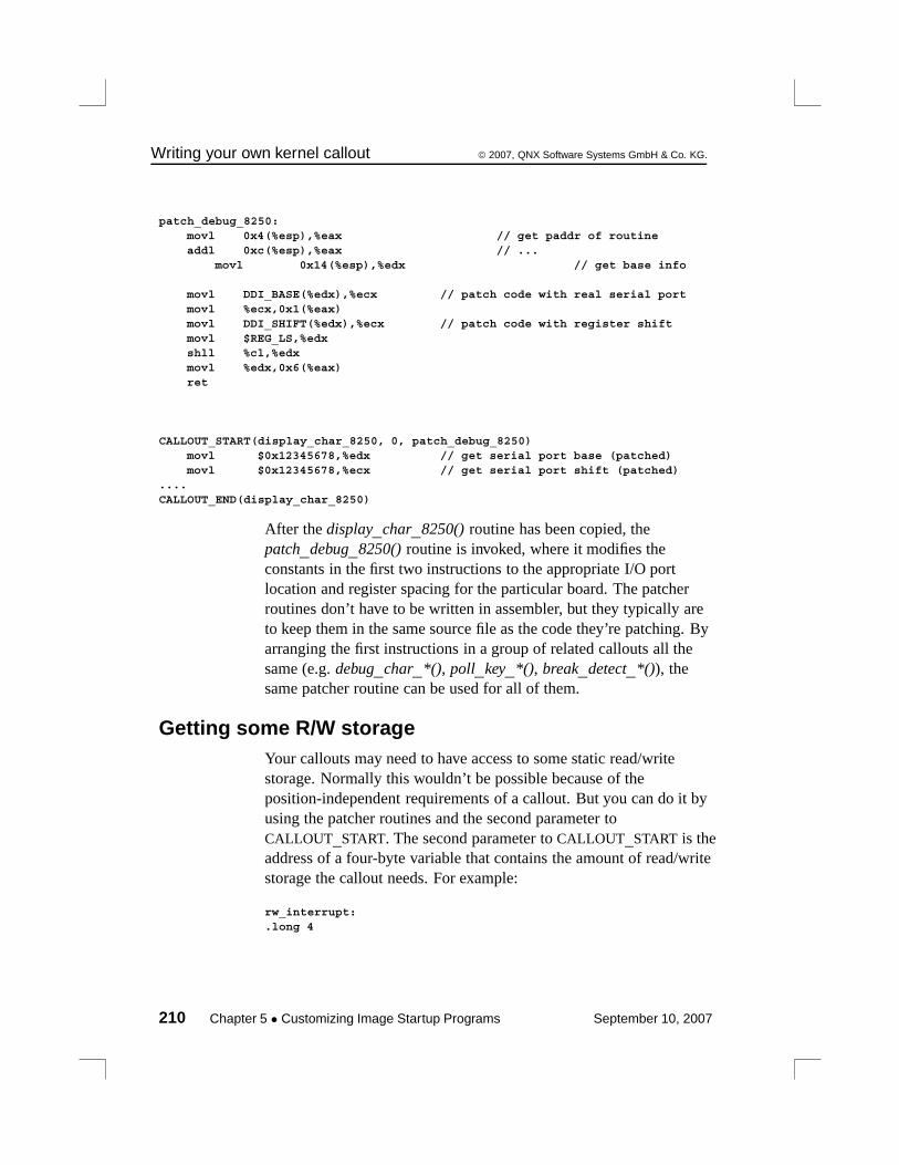
Writing your own kernel callout © 2007, QNX Software Systems GmbH & Co. KG.
patch_debug_8250:movl 0x4(%esp),%eax // get paddr of routineaddl 0xc(%esp),%eax // ...
movl 0x14(%esp),%edx // get base info
movl DDI_BASE(%edx),%ecx // patch code with real serial portmovl %ecx,0x1(%eax)movl DDI_SHIFT(%edx),%ecx // patch code with register shiftmovl $REG_LS,%edxshll %cl,%edxmovl %edx,0x6(%eax)ret
CALLOUT_START(display_char_8250, 0, patch_debug_8250)movl $0x12345678,%edx // get serial port base (patched)movl $0x12345678,%ecx // get serial port shift (patched)
....CALLOUT_END(display_char_8250)
After the display_char_8250() routine has been copied, thepatch_debug_8250() routine is invoked, where it modifies theconstants in the first two instructions to the appropriate I/O portlocation and register spacing for the particular board. The patcherroutines don’t have to be written in assembler, but they typically areto keep them in the same source file as the code they’re patching. Byarranging the first instructions in a group of related callouts all thesame (e.g. debug_char_*(), poll_key_*(), break_detect_*()), thesame patcher routine can be used for all of them.
Getting some R/W storageYour callouts may need to have access to some static read/writestorage. Normally this wouldn’t be possible because of theposition-independent requirements of a callout. But you can do it byusing the patcher routines and the second parameter toCALLOUT_START. The second parameter to CALLOUT_START is theaddress of a four-byte variable that contains the amount of read/writestorage the callout needs. For example:
rw_interrupt:.long 4
210 Chapter 5 • Customizing Image Startup Programs September 10, 2007
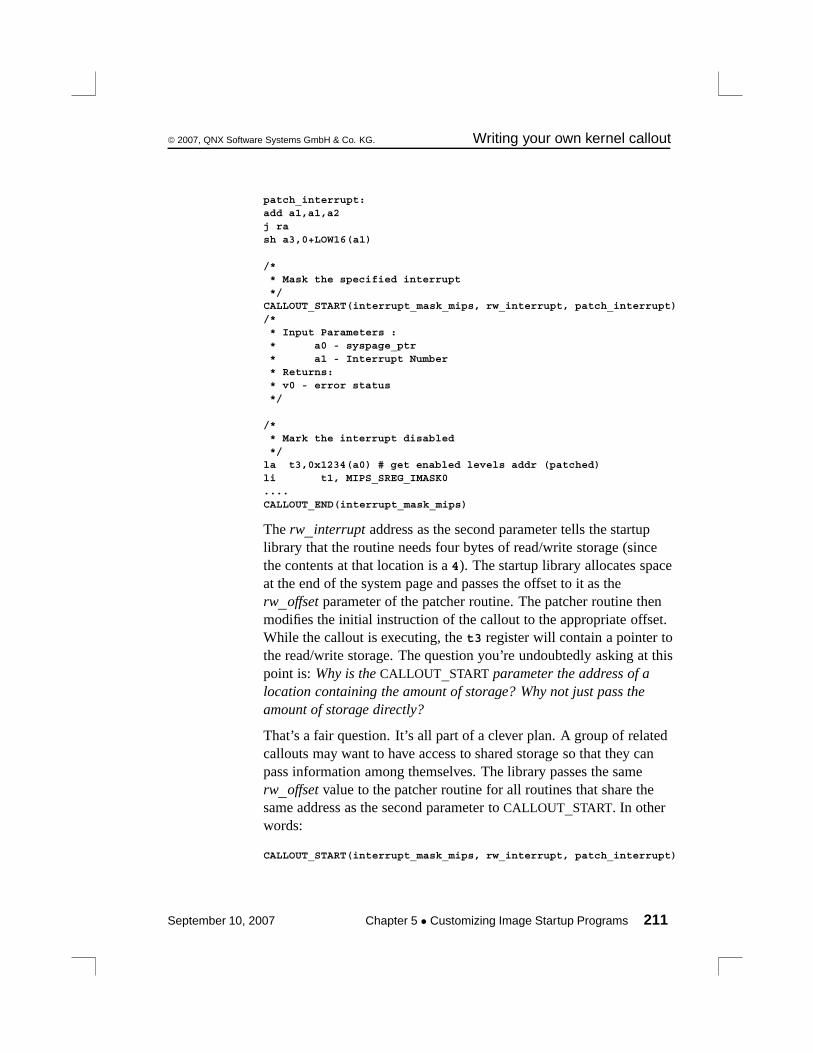
© 2007, QNX Software Systems GmbH & Co. KG. Writing your own kernel callout
patch_interrupt:add a1,a1,a2j rash a3,0+LOW16(a1)
/** Mask the specified interrupt*/
CALLOUT_START(interrupt_mask_mips, rw_interrupt, patch_interrupt)/** Input Parameters :* a0 - syspage_ptr* a1 - Interrupt Number* Returns:* v0 - error status*/
/** Mark the interrupt disabled*/
la t3,0x1234(a0) # get enabled levels addr (patched)li t1, MIPS_SREG_IMASK0....CALLOUT_END(interrupt_mask_mips)
The rw_interrupt address as the second parameter tells the startuplibrary that the routine needs four bytes of read/write storage (sincethe contents at that location is a 4). The startup library allocates spaceat the end of the system page and passes the offset to it as therw_offset parameter of the patcher routine. The patcher routine thenmodifies the initial instruction of the callout to the appropriate offset.While the callout is executing, the t3 register will contain a pointer tothe read/write storage. The question you’re undoubtedly asking at thispoint is: Why is the CALLOUT_START parameter the address of alocation containing the amount of storage? Why not just pass theamount of storage directly?
That’s a fair question. It’s all part of a clever plan. A group of relatedcallouts may want to have access to shared storage so that they canpass information among themselves. The library passes the samerw_offset value to the patcher routine for all routines that share thesame address as the second parameter to CALLOUT_START. In otherwords:
CALLOUT_START(interrupt_mask_mips, rw_interrupt, patch_interrupt)
September 10, 2007 Chapter 5 • Customizing Image Startup Programs 211
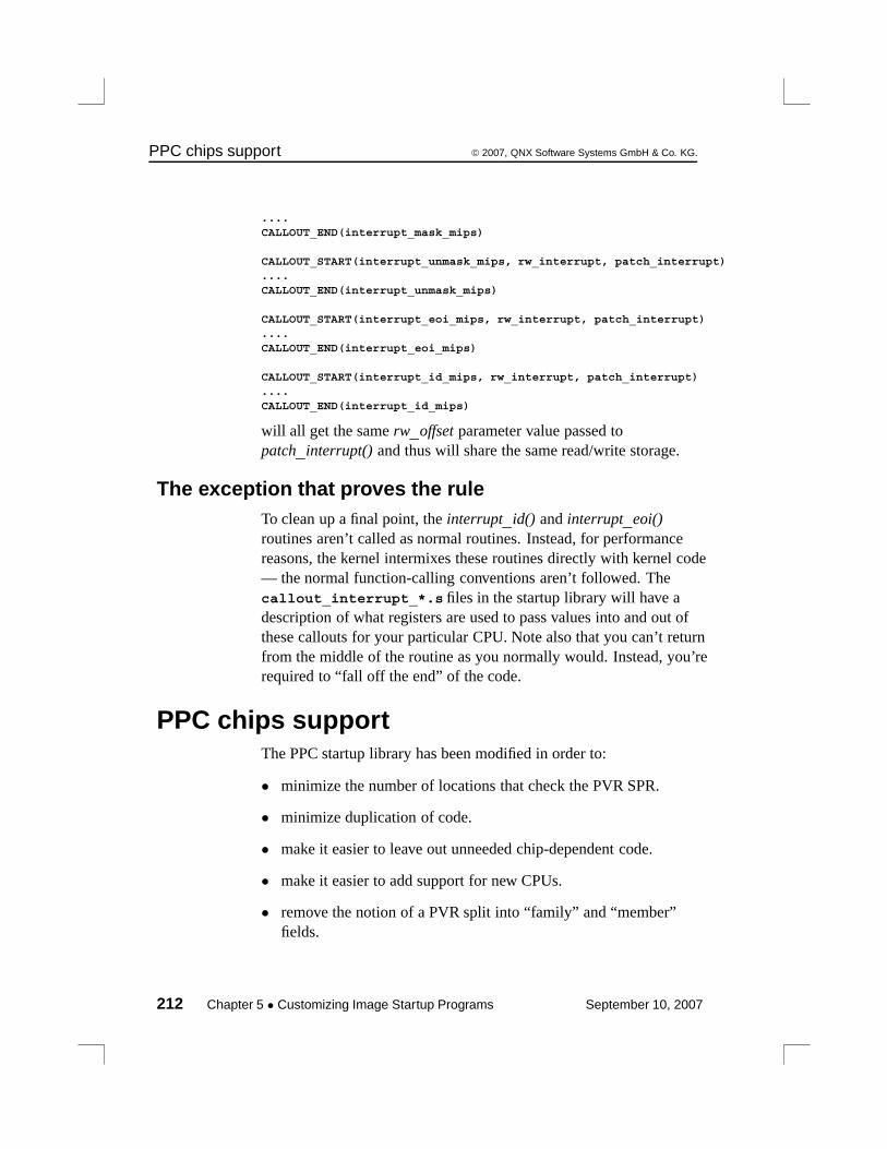
PPC chips support © 2007, QNX Software Systems GmbH & Co. KG.
....CALLOUT_END(interrupt_mask_mips)
CALLOUT_START(interrupt_unmask_mips, rw_interrupt, patch_interrupt)....CALLOUT_END(interrupt_unmask_mips)
CALLOUT_START(interrupt_eoi_mips, rw_interrupt, patch_interrupt)....CALLOUT_END(interrupt_eoi_mips)
CALLOUT_START(interrupt_id_mips, rw_interrupt, patch_interrupt)....CALLOUT_END(interrupt_id_mips)
will all get the same rw_offset parameter value passed topatch_interrupt() and thus will share the same read/write storage.
The exception that proves the ruleTo clean up a final point, the interrupt_id() and interrupt_eoi()routines aren’t called as normal routines. Instead, for performancereasons, the kernel intermixes these routines directly with kernel code— the normal function-calling conventions aren’t followed. Thecallout_interrupt_*.s files in the startup library will have adescription of what registers are used to pass values into and out ofthese callouts for your particular CPU. Note also that you can’t returnfrom the middle of the routine as you normally would. Instead, you’rerequired to “fall off the end” of the code.
PPC chips supportThe PPC startup library has been modified in order to:
• minimize the number of locations that check the PVR SPR.
• minimize duplication of code.
• make it easier to leave out unneeded chip-dependent code.
• make it easier to add support for new CPUs.
• remove the notion of a PVR split into “family” and “member”fields.
212 Chapter 5 • Customizing Image Startup Programs September 10, 2007
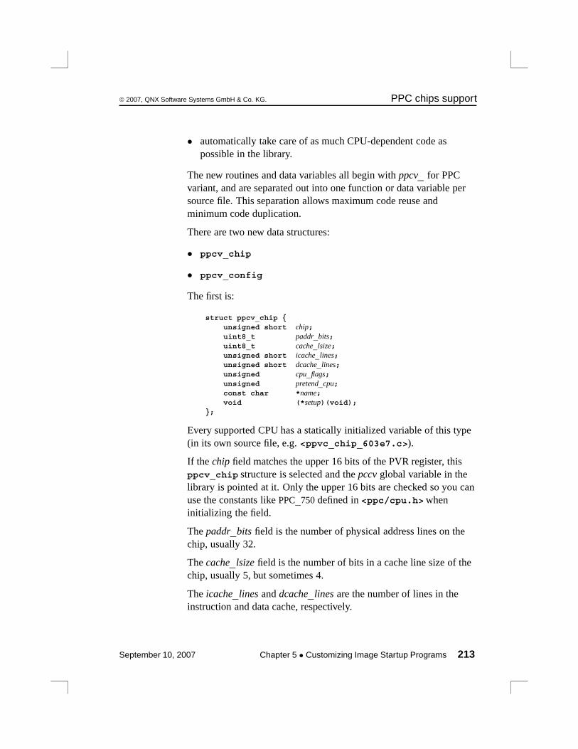
© 2007, QNX Software Systems GmbH & Co. KG. PPC chips support
• automatically take care of as much CPU-dependent code aspossible in the library.
The new routines and data variables all begin with ppcv_ for PPCvariant, and are separated out into one function or data variable persource file. This separation allows maximum code reuse andminimum code duplication.
There are two new data structures:
• ppcv_chip
• ppcv_config
The first is:
struct ppcv_chip {unsigned short chip;uint8_t paddr_bits;uint8_t cache_lsize;unsigned short icache_lines;unsigned short dcache_lines;unsigned cpu_flags;unsigned pretend_cpu;const char *name;void (*setup)(void);
};
Every supported CPU has a statically initialized variable of this type(in its own source file, e.g. <ppvc_chip_603e7.c>).
If the chip field matches the upper 16 bits of the PVR register, thisppcv_chip structure is selected and the pccv global variable in thelibrary is pointed at it. Only the upper 16 bits are checked so you canuse the constants like PPC_750 defined in <ppc/cpu.h> wheninitializing the field.
The paddr_bits field is the number of physical address lines on thechip, usually 32.
The cache_lsize field is the number of bits in a cache line size of thechip, usually 5, but sometimes 4.
The icache_lines and dcache_lines are the number of lines in theinstruction and data cache, respectively.
September 10, 2007 Chapter 5 • Customizing Image Startup Programs 213
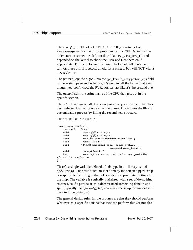
PPC chips support © 2007, QNX Software Systems GmbH & Co. KG.
The cpu_flags field holds the PPC_CPU_* flag constants from<ppc/syspage.h> that are appropriate for this CPU. Note that theolder startups sometimes left out flags like PPC_CPU_HW_HT anddepended on the kernel to check the PVR and turn them on ifappropriate. This is no longer the case. The kernel will continue toturn on those bits if it detects an old style startup, but will NOT with anew style one.
The pretend_cpu field goes into the ppc_kerinfo_entry.pretend_cpu fieldof the system page and as before, it’s used to tell the kernel that eventhough you don’t know the PVR, you can act like it’s the pretend one.
The name field is the string name of the CPU that gets put in thecpuinfo section.
The setup function is called when a particular ppcv_chip structure hasbeen selected by the library as the one to use. It continues the librarycustomization process by filling the second new structure.
The second data structure is:
struct ppcv_config {unsigned family;void (*cpuconfig1)(int cpu);void (*cpuconfig2)(int cpu);void (*cpuinfo)(struct cpuinfo_entry *cpu);void (*qtime)(void);void *(*map)(unsigned size, paddr_t phys,
unsigned prot_flags);void (*unmap)(void *);int (*mmu_info)(enum mmu_info info, unsigned tlb);
//NYI: tlb_read/write};
There’s a single variable defined of this type in the library, calledppcv_config. The setup function identified by the selected ppcv_chipis responsible for filling in the fields with the appropriate routines forthe chip. The variable is statically initialized with a set of do-nothingroutines, so if a particular chip doesn’t need something done in onespot (typically the cpuconfig[1/2] routines), the setup routine doesn’thave to fill anything in).
The general design rules for the routines are that they should performwhatever chip-specific actions that they can perform that are not also
214 Chapter 5 • Customizing Image Startup Programs September 10, 2007
© 2007, QNX Software Systems GmbH & Co. KG. PPC chips support
board-specific. For example, the old startup main() functions wouldsometimes turn off data translation, since some IPLs turned it on.With the new startups this is handled automatically by the library. Onthe other hand, both the old and new startups call theppc700_init_l2_cache() manually in main(), since the exact bits toput in the L2CR register are board-specific. The routines in thelibraries should be modified to work with the IPL and initialize theCPU properly, rather than modifying the board-specific code to hackaround it (e.g. the aforementioned disabling of data translation).
The setup routine might also initialize a couple of other freestandingvariables that other support routines use to avoid them having tocheck the PVR value again (e.g. see the ppc600_set_clock_freqs()and ppcv_setup_7450() functions for an example).
The new startup (and kernel, when used with a new startup) no longerdepends on the PVR to identify the chip family. Instead the “family”field is filled in with a PPC_FAMILY_* value from<ppc/syspage.h>. This is transferred to theppc_kerinfo_entry.family field on the system page, which thekernel uses to verify that the right version of procnto is being used.
If the kernel sees a value of PPC_FAMILY_UNKNOWN (zero) in thesystem page, it assumes that an old style startup is being used and willattempt to determine the family (and cpuinfo->flags) fields on itsown. DO NOT USE that feature with new startups.
Fill in the ppcv_config.family and ppcv_chip.cpu_flags field properly.The cpuconfig1 routine is used to configure the CPU for use instartup, and is called early before main() is called. For example, itmakes sure that instruction and data translation is turned off, theexception table is pointed at low memory, etc. It’s called once forevery CPU in an SMP system, with the cpu parm indicating the CPUnumber being initialized.
The cpuconfig2 routine is called just before startup transfers control tothe first bootstrap executable in the image file system. It configuresthe CPU for running in the bootstrap environment, e.g. turning onCPU-specific features such as HID0 and HID1 bits. Again it’s called
September 10, 2007 Chapter 5 • Customizing Image Startup Programs 215

PPC chips support © 2007, QNX Software Systems GmbH & Co. KG.
once per CPU in an SMP system with the cpu parm indicating whichone.
The cpuinfo routine is called by init_one_cpuinfo() to fill in thecpuinfo_entry structure for each CPU. The qtime routine is calledby init_qtime() to set up the qtime syspage section.
The map and unmap routines used to create/delete memory mappingsfor startup and callout use, are called by:
• startup_map_io
• startup_map_memory
• startup_unmap_io
• startup_unmap_memory
• callout_map_io
• callout_map_memory
There’s one more data variable to mention. This is ppcv_list, which isa statically initialized array of pointers to ppcv_chip structures. Thedefault version of the variable in the library has a list of all theppcv_chip variables defined by the library so, by default, the library iscapable of handling any type of PPC chip.
By defining a ppcv_list variable in the board-specific directory andadding only the ppcv_chip_* variable(s) that can be used with thatboard, all the chip-specific code for the processors that can’t possiblybe there will be left out.
For example, the new shasta-ssc startup with the default ppcv_list isabout 1 KB bigger than the old version. By restricting the ppcv_list toonly ppcv_chip_750, the new startup drops to 1 KB smaller than theoriginal.
216 Chapter 5 • Customizing Image Startup Programs September 10, 2007
© 2007, QNX Software Systems GmbH & Co. KG. PPC chips support
Adding a new CPU to the startup libraryFor a CPU called xyz, create a <ppcv_chip_xyz.c> and in it put anappropriately initialized struct ppcv_chip ppcv_chip_xyz variable.Add the ppcv_chip_xyz variable to the default ppcv_list (in<ppcv_list.c>).
If you were able to use an already existing ppcv_setup_*() functionfor the ppcv_chip_xyz initialization, you’re done. Otherwise, create a<ppcv_setup_xyz.c> file with the properly codedppcv_setup_xyz() function in it (don’t forget to add the prototype to<cpu_startup.h>).
If you were able to use already existing ppcv_* routines in theppcv_setup_xyz() function, you’re done. Otherwise, create theroutines in the appropriate <ppcv_*_xyz.c> files (don’t forget toadd the prototype(s) to <cpu_startup.h>). When possible, codethe routines in an object-oriented manner, calling already existingroutines to fill more generic information, e.g. ppcv_cpuconfig2_700()uses ppcv_cpuconfig2_600() to do most of the work and then it justfills in the 700 series-specific info.
With the new design, the following routines are now deprecated (andthey spit out a message to that effect if you call them):
ppc600_init_features(), ppc600_init_caches(),ppc600_flush_caches()
Handled automatically by the library now.
ppc7450_init_l2_cache()
Use ppc700_init_l2_cache() instead.
September 10, 2007 Chapter 5 • Customizing Image Startup Programs 217

Chapter 6
Customizing the Flash Filesystem
In this chapter. . .Introduction 221Driver structure 222Building your flash filesystem driver 224Example: The devf-ram driver 244
September 10, 2007 Chapter 6 • Customizing the Flash Filesystem 219

© 2007, QNX Software Systems GmbH & Co. KG. Introduction
IntroductionNeutrino ships with a small number of prebuilt flash filesystemdrivers for particular embedded systems. For the currently availabledrivers, look in the ${QNX_TARGET}/${PROCESSOR}/sbindirectory. The flash filesystem drivers are named devf-system, wheresystem is derived from the name of the embedded system. You’ll finda general description of the flash filesystem in the System Architecturebook and descriptions of all the flash filesystem drivers in the UtilitiesReference.
If a driver isn’t provided for your particular target embedded system,you should first try our “generic” driver (devf-generic). Thisdriver often — but not always — works with standard flash hardware.The driver assumes a supported memory technology driver (MTD)and linear memory addressing.
If none of our drivers works for your hardware, you’ll need to buildyour own driver. We provide all the source code needed for you tocustomize a flash filesystem driver for your target. After installation,look in the bsp_working_dir/src/hardware/flash/boardsdirectory — you’ll find a subdirectory for each board we support.
Besides the boards directory, you should also refer to the followingsources to find out what boards/drivers we currently support:
• QNX docs (BSP docs as well as devf-* entries in UtilitiesReference).
• the Community area of our website, www.qnx.com
Note that we currently support customizing a driver only forembedded systems with onboard flash memory (also called a residentflash array or RFA). If you need support for removable media likePCMCIA or compact or miniature memory cards, then please contactus.
September 10, 2007 Chapter 6 • Customizing the Flash Filesystem 221
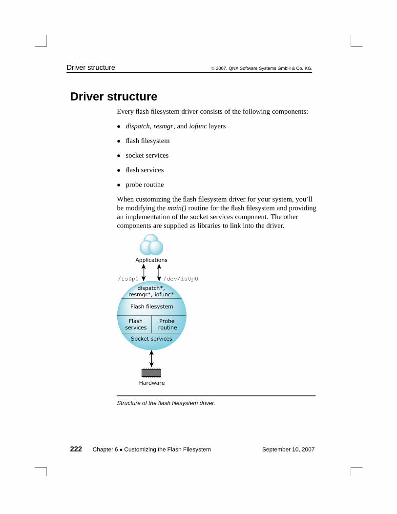
Driver structure © 2007, QNX Software Systems GmbH & Co. KG.
Driver structureEvery flash filesystem driver consists of the following components:
• dispatch, resmgr, and iofunc layers
• flash filesystem
• socket services
• flash services
• probe routine
When customizing the flash filesystem driver for your system, you’llbe modifying the main() routine for the flash filesystem and providingan implementation of the socket services component. The othercomponents are supplied as libraries to link into the driver.
/fs0p0 /dev/fs0p0
Flash filesystem
Socket services
Flash
services
Hardware
dispatch*,resmgr*, iofunc*
Probe
routine
Applications
Structure of the flash filesystem driver.
222 Chapter 6 • Customizing the Flash Filesystem September 10, 2007
© 2007, QNX Software Systems GmbH & Co. KG. Driver structure
resmgr and iofunc layersLike all Neutrino device managers, the flash filesystem uses thestandard resmgr/iofunc interface and accepts the standard set ofresource manager messages. The flash filesystem turns thesemessages into read, write, and erase operations on the underlyingflash devices.
For example, an open message would result in code being executedthat would read the necessary filesystem data structures on the flashdevice and locate the requested file. A subsequent write message willmodify the contents of the file on flash. Special functions, such aserasing the flash device, are implemented using devctl messages.
Flash filesystem componentThe flash filesystem itself is the “personality” component of the flashfilesystem driver. The filesystem contains all the code to processfilesystem requests and to manage the filesystem on the flash devices.The socket and flash services components are used by the flashfilesystem to access the flash devices.
The code for the flash filesystem component is platform-independentand is provided in the libfs-flash3.a library.
Socket services componentThe socket services component is responsible for any system-specificinitialization required by the flash devices at startup and for providingaddressability to the flash devices (this applies mainly to windowedflash interfaces).
Before reading/writing the flash device, other components will usesocket services to make sure the required address range can beaccessed. On systems where the flash device is linearly mapped intothe processor address space, addressability is trivial. On systemswhere the flash is either bank-switched or hidden behind some otherinterface (such as PCMCIA), addressability is more complicated.
The socket services component is the one that will require the mostcustomization for your system.
September 10, 2007 Chapter 6 • Customizing the Flash Filesystem 223
Building your flash filesystem driver © 2007, QNX Software Systems GmbH & Co. KG.
Flash services componentThe flash services component contains the device-specific coderequired to write and erase particular flash devices. This component isalso called the memory technology driver (MTD).
The directory ${QNX_TARGET}/${PROCESSOR}/lib contains theMTD library libmtd-flash.a to handle the flash devices wesupport.
bsp_working_dir/src/hardware/flash/mtd-flash containssource for the libmtd-flash.a library.
Probe routine componentThe probe routine uses a special algorithm to estimate the size of theflash array. Since the source code for the probe routine is available,you should be able to readily identify any failures in the sizingalgorithm.
Building your flash filesystem driverBefore you start customizing your own flash filesystem driver, youshould examine the source of all the sample drivers supplied. Mostlikely, one of the existing drivers can be easily customized to supportyour system. If not, the devf-ram source provides a good template tostart with.
The source treeThe source files are organized as follows:
224 Chapter 6 • Customizing the Flash Filesystem September 10, 2007
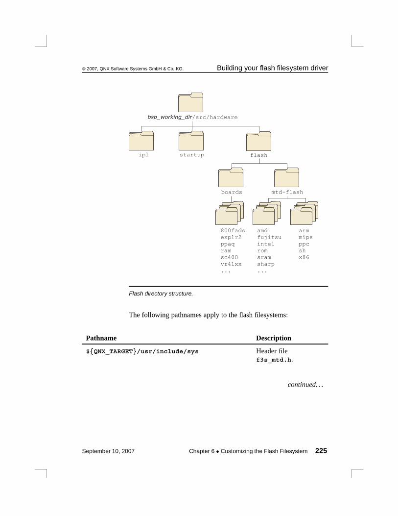
© 2007, QNX Software Systems GmbH & Co. KG. Building your flash filesystem driver
startupipl flash
bsp_working_dir/src/hardware
boards
800fadsexplr2ppaqramsc400vr41xx...
mipsppc
x86
mtd-flash
amdfujitsuintel
sharp
romsram
...
arm
sh
Flash directory structure.
The following pathnames apply to the flash filesystems:
Pathname Description
${QNX_TARGET}/usr/include/sys Header filef3s_mtd.h.
continued. . .
September 10, 2007 Chapter 6 • Customizing the Flash Filesystem 225
Building your flash filesystem driver © 2007, QNX Software Systems GmbH & Co. KG.
Pathname Description
${QNX_TARGET}/usr/include/fs Header filesf3s_api.h,f3s_socket.h, andf3s_flash.h.
${QNX_TARGET}/${PROCESSOR}/lib Libraries for flashfilesystem and flashservices.
bsp_working_dir/src/hardware/flash/boards Source code for socketservices.
bsp_working_dir/src/hardware/flash/mtd-flash Source code for flashservices as well as forprobe routine andhelper functions.
Before you modify any source, you should:
1 Create a new directory for your driver in thebsp_working_dir/src/hardware/flash/boards directory.
2 Copy the files from the sample directory you want into yournew directory.
For example, to create a driver called myboard based on the800FADS board example, you would:
cd bsp_working_dir/hardware/flash/boardsmkdir myboardcp -cRv 800fads myboardcd myboardmake clean
The copy command (cp) specifies a recursive copy (the -R option).This will copy all files from the specified source directory includingthe subdirectory indicating which CPU this driver should be built for.In our example above, the 800fads directory has a ppc subdirectory— this will cause the new driver (myboard in our example) to bebuilt for the PowerPC.
226 Chapter 6 • Customizing the Flash Filesystem September 10, 2007
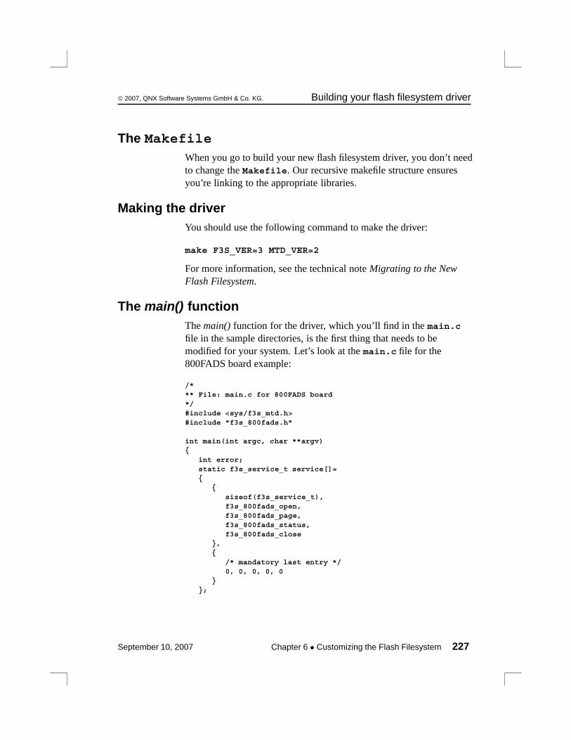
© 2007, QNX Software Systems GmbH & Co. KG. Building your flash filesystem driver
The MakefileWhen you go to build your new flash filesystem driver, you don’t needto change the Makefile. Our recursive makefile structure ensuresyou’re linking to the appropriate libraries.
Making the driverYou should use the following command to make the driver:
make F3S_VER=3 MTD_VER=2
For more information, see the technical note Migrating to the NewFlash Filesystem.
The main() functionThe main() function for the driver, which you’ll find in the main.cfile in the sample directories, is the first thing that needs to bemodified for your system. Let’s look at the main.c file for the800FADS board example:
/*** File: main.c for 800FADS board*/#include <sys/f3s_mtd.h>#include "f3s_800fads.h"
int main(int argc, char **argv){
int error;static f3s_service_t service[]={
{sizeof(f3s_service_t),f3s_800fads_open,f3s_800fads_page,f3s_800fads_status,f3s_800fads_close
},{
/* mandatory last entry */0, 0, 0, 0, 0
}};
September 10, 2007 Chapter 6 • Customizing the Flash Filesystem 227
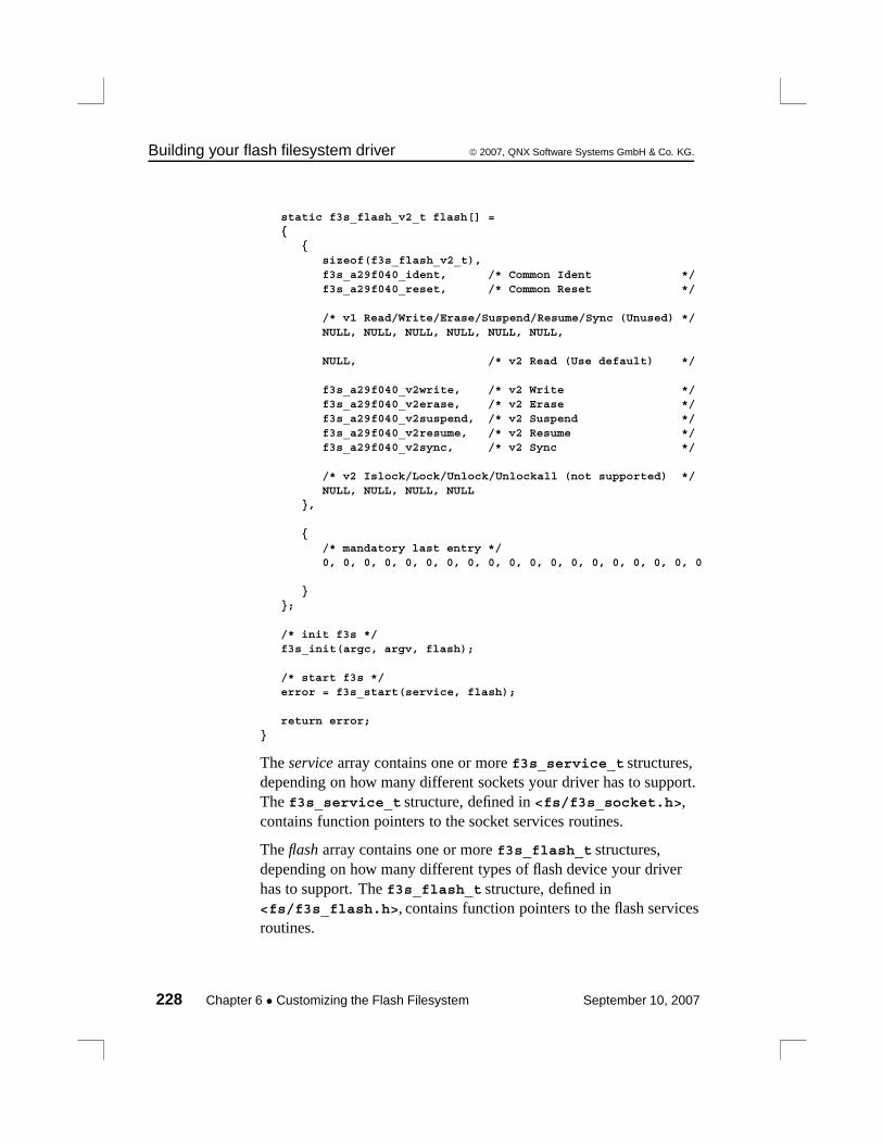
Building your flash filesystem driver © 2007, QNX Software Systems GmbH & Co. KG.
static f3s_flash_v2_t flash[] ={
{sizeof(f3s_flash_v2_t),f3s_a29f040_ident, /* Common Ident */f3s_a29f040_reset, /* Common Reset */
/* v1 Read/Write/Erase/Suspend/Resume/Sync (Unused) */NULL, NULL, NULL, NULL, NULL, NULL,
NULL, /* v2 Read (Use default) */
f3s_a29f040_v2write, /* v2 Write */f3s_a29f040_v2erase, /* v2 Erase */f3s_a29f040_v2suspend, /* v2 Suspend */f3s_a29f040_v2resume, /* v2 Resume */f3s_a29f040_v2sync, /* v2 Sync */
/* v2 Islock/Lock/Unlock/Unlockall (not supported) */NULL, NULL, NULL, NULL
},
{/* mandatory last entry */0, 0, 0, 0, 0, 0, 0, 0, 0, 0, 0, 0, 0, 0, 0, 0, 0, 0, 0
}};
/* init f3s */f3s_init(argc, argv, flash);
/* start f3s */error = f3s_start(service, flash);
return error;}
The service array contains one or more f3s_service_t structures,depending on how many different sockets your driver has to support.The f3s_service_t structure, defined in <fs/f3s_socket.h>,contains function pointers to the socket services routines.
The flash array contains one or more f3s_flash_t structures,depending on how many different types of flash device your driverhas to support. The f3s_flash_t structure, defined in<fs/f3s_flash.h>, contains function pointers to the flash servicesroutines.
228 Chapter 6 • Customizing the Flash Filesystem September 10, 2007
© 2007, QNX Software Systems GmbH & Co. KG. Building your flash filesystem driver
The f3s_init() and f3s_start() functions are defined in the<fs/f3s_api.h> header file.
Don’t use the <fs/f3s_socket.h>, <fs/f3s_flash.h>, and<fs/f3s_api.h> header files directly. Instead, you should include<sys/f3s_mtd.h> for backward and forward compatibility.
f3s_init()f3s_init (int argc,
char **argv,f3s_flash_t *flash_vect)
This function passes the command-line arguments to the flashfilesystem component, which then initializes itself.
f3s_start()f3s_start (f3s_service_t *service,
f3s_flash_t *flash)
This function passes the service and flash arrays to the filesystemcomponent so it can make calls to the socket and flash services, andthen starts the driver. This function returns only when the driver isabout to exit.
When writing your main.c, you’ll need to enter:
• the socket services functions for each socket in the service array
• the flash services functions for each flash device in the flash array.
If you have a system with only one socket consisting of the same flashdevices, then there will be only a single entry in each array.
Socket services interfaceThe socket services interface, defined in the <fs/f3s_socket.h>header file, consists of the following functions:
• f3s_open()
• f3s_page()
• f3s_status()
September 10, 2007 Chapter 6 • Customizing the Flash Filesystem 229
Building your flash filesystem driver © 2007, QNX Software Systems GmbH & Co. KG.
• f3s_close()
• f3s_socket_option()
• f3s_socket_syspage()
f3s_open()int32_t f3s_open (f3s_socket_t *socket,
uint32_t flags)
This function is called to initialize a socket or a particular window ina socket. The function should process any socket options, initializeand map in the flash devices, and initialize the socket structure.
f3s_page()uint8_t *f3s_page (f3s_socket_t *socket,
uint32_t flags,uint32_t offset,int32_t *size)
This function is called to access a window_size sized window ataddress offset from the start of the device; it must be provided for bothbank-switched and linearly mapped flash devices. If the sizeparameter is non-NULL, you should set it to the size of the window.The function must return a pointer suitable for accessing the device ataddress offset. On error, it should return NULL and set errno toERANGE.
f3s_status()int32_t f3s_status (f3s_socket_t *socket,
uint32_t flags)
This function is called to get the socket status. It’s used currently onlyfor interfaces that support dynamic insertion and removal. Foronboard flash, you should simply return EOK.
f3s_close()void f3s_close (f3s_socket_t *socket,
uint32_t flags)
This function is called to close the socket. If you need to, you candisable the flash device and remove any programming voltage, etc.
The following flags are defined for the flags parameter in the socketfunctions:
230 Chapter 6 • Customizing the Flash Filesystem September 10, 2007
© 2007, QNX Software Systems GmbH & Co. KG. Building your flash filesystem driver
F3S_POWER_VCC
Apply read power.
F3S_POWER_VPP
Apply program power.
F3S_OPER_SOCKET
Operation applies to socket given in socket_index.
F3S_OPER_WINDOW
Operation applies to window given in window_index.
The socket parameter is used for passing arguments and returningresults from the socket services and for storing information abouteach socket. To handle complex interfaces such as PCMCIA, thestructure has been defined so that there can be more than one socket;each socket can have more than one window. A simple linear flasharray would have a single socket and no windows.
The socket structure is defined as:
typedef struct f3s_socket_s{
/** these fields are initialized by the flash file system* and later validated and set by the socket services*/
_Uint16t struct_size; /* size of this structure */_Uint16t status; /* status of this structure */_Uint8t *option; /* option string from flashio */_Uint16t socket_index; /* index of socket */_Uint16t window_index; /* index of window */
/** these fields are initialized by the socket services and later* referenced by the flash file system*/
_Uint8t *name; /* name of driver */_Paddr64t address; /* physical address 0 for allocated */_Uint32t window_size; /* size of window power of two mandatory */_Uint32t array_offset; /* offset of array 0 for based */_Uint32t array_size; /* size of array 0 for window_size */_Uint32t unit_size; /* size of unit 0 for probed */_Uint32t flags; /* flags for capabilities */
September 10, 2007 Chapter 6 • Customizing the Flash Filesystem 231
Building your flash filesystem driver © 2007, QNX Software Systems GmbH & Co. KG.
_Uint16t bus_width; /* width of bus */_Uint16t window_num; /* number of windows 0 for not windowed */
/** these fields are initialized by the socket services and later* referenced by the socket services*/
_Uint8t* memory; /* access pointer for window memory */void *socket_handle; /* socket handle pointer for external
library */void *window_handle; /* window handle pointer for external
library */
/** this field is modified by the socket services as different window* pages are selected*/
_Uint32t window_offset; /* offset of window */}f3s_socket_t;
Here’s a description of the fields:
option Option string from command line; parse using thef3s_socket_option() function.
socket_index Current socket.
window_index Current window.
name String containing name of driver.
address Base address of flash array.
window_size Size of window in bytes.
array_size Size of array in bytes; 0 indicates unknown.
unit_size Size of unit in bytes; 0 indicates probed.
flags The flags field is currently unused.
bus_width Width of the flash devices in bytes.
window_num Number of windows in socket; 0 indicatesnon-windowed.
232 Chapter 6 • Customizing the Flash Filesystem September 10, 2007

© 2007, QNX Software Systems GmbH & Co. KG. Building your flash filesystem driver
memory Free for use by socket services; usually storescurrent window address.
socket_handle Free for use by socket services; usually storespointer to any extra data for socket.
window_handle Free for use by socket services; usually storespointer to any extra data for window.
window_offset Offset of window from base of device in bytes.
Options parsingThe socket services should parse any applicable options beforeinitializing the flash devices in the f3s_open() function. Two supportfunctions are provided for this:
f3s_socket_option()int f3s_socket_option (f3s_socket_t *socket)
Parse the driver command-line options that apply to the socketservices.
Currently the following options are defined:
-s baseaddress,windowsize, arrayoffset, arraysize, unitsize, buswidth, interleave
where:
baseaddress Base address of the socket/window.
windowsize Size of the socket/window.
arrayoffset Offset of window from base of devices in bytes.
arraysize Size of array in bytes, 0 indicates unknown.
buswidth Memory bus attached to the flash chips.
interleave Number of physical chips interleaved to form alarger logical chip (e.g. two 16-bit chips interleavedto form a 32-bit logical chip).
September 10, 2007 Chapter 6 • Customizing the Flash Filesystem 233

Building your flash filesystem driver © 2007, QNX Software Systems GmbH & Co. KG.
f3s_socket_syspage()int f3s_socket_syspage (f3s_socket_t *socket)
Parse the syspage options that apply to the socket services.
The syspage options allow the socket services to get any informationabout the flash devices in the system that is collected by the startupprogram and stored in the syspage. See the chapter on CustomizingImage Startup Programs for more information.
Flash services interfaceThe flash services interface, defined in the <fs/f3s_flash.h>header file, consists of the following functions:
• f3s_ident()
• f3s_reset()
• f3s_v2read()
• f3s_v2write()
• f3s_v2erase()
• f3s_v2suspend()
• f3s_v2resume()
• f3s_v2sync()
• f3s_v2islock()
• f3s_v2lock()
• f3s_v2unlock()
• f3s_v2unlockall()
234 Chapter 6 • Customizing the Flash Filesystem September 10, 2007

© 2007, QNX Software Systems GmbH & Co. KG. Building your flash filesystem driver
The values for the flags parameter are defined in<fs/s3s_flash.h>. The most important one isF3S_VERIFY_WRITE. If this is set, the routine must perform aread-back verification after the write as a double check that the writesucceeded. Occasionally, however, the hardware reports success evenwhen the write didn’t work as expected.
f3s_ident()int32_t f3s_ident (f3s_dbase_t *dbase,
f3s_access_t *access,uint32_t text_offset,uint32_t flags)
Identifies the flash device at address text_offset and fills in the dbasestructure with information about the device type and geometry.
f3s_reset()void f3s_reset (f3s_dbase_t *dbase,
f3s_access_t *access,uint32_t text_offset)
Resets the flash device at address text_offset into the defaultread-mode after calling the fs3_ident() function or after a device error.
f3s_v2read()int32_t f3s_v2read (f3s_dbase_t *dbase,
f3s_access_t *access,_Uint32t flags,_Uint32t text_offset,_Int32t buffer_size,_Uint8t *buffer);
This optional function is called to read buffer_size bytes from addresstext_offset into buffer. Normally the flash devices will be read directlyvia memcpy().
On success, it should return the number of bytes read. If an erroroccurs, it should return -1 with errno set to one of the following:
EIO Recoverable I/O error (e.g. failed due to lowpower, but corruption is localized and block willbe usable after erasing).
September 10, 2007 Chapter 6 • Customizing the Flash Filesystem 235

Building your flash filesystem driver © 2007, QNX Software Systems GmbH & Co. KG.
EFAULT Unrecoverable I/O error (e.g. block no longerusable).
EINVAL Invalid command error.
ERANGE Flash memory access out of range (viaservice->page function).
ENODEV Flash no longer accessible (e.g. flash removed).
ESHUTDOWN Critical error; shut down the flash driver.
f3s_v2write()int32_t f3s_v2write (f3s_dbase_t *dbase,
f3s_access_t *access,_Uint32t flags,_Uint32t text_offset,_Int32t buffer_size,_Uint8t *buffer);
This function writes buffer_size bytes from buffer to addresstext_offset.
On success, it should return the number of bytes written. If an erroroccurs, it should return -1 with errno set to one of the following:
EIO Recoverable I/O error (e.g. failed due to low poweror write failed, but corruption is localized andblock will be usable after erasing).
EFAULT Unrecoverable I/O error (e.g. block no longerusable).
EROFS Block is write protected.
EINVAL Invalid command error.
ERANGE Flash memory access out of range (viaservice->page function).
ENODEV Flash no longer accessible (e.g. flash removed).
ESHUTDOWN Critical error; shut down the flash driver.
236 Chapter 6 • Customizing the Flash Filesystem September 10, 2007
© 2007, QNX Software Systems GmbH & Co. KG. Building your flash filesystem driver
f3s_v2erase()int f3s_v2erase (f3s_dbase_t *dbase,
f3s_access_t *access,_Uint32t flags,_Uint32t text_offset);
This function begins erasing the flash block containing the text_offset.It can optionally determine if an error has already occurred, or it canjust return EOK and let f3s_v2sync() detect any error.
On success, it should return EOK. If an error occurs, it should returnone of the following:
EIO Recoverable I/O error (e.g. failed due to low power orerase failed, but corruption is localized and block willbe usable after an erase)
EFAULT Unrecoverable I/O error (e.g. block no longer usable)
EROFS Block is write protected
EINVAL Invalid command error
EBUSY Flash busy, try again (e.g. erasing same block twice)
ERANGE Flash memory access out of range (via service->pagefunction)
ENODEV Flash no longer accessible (e.g. flash removed)
ESHUTDOWN
Critical error; shut down the flash driver.
f3s_v2suspend()int f3s_v2suspend (f3s_dbase_t *dbase,
f3s_access_t *access,_Uint32t flags,_Uint32t text_offset);
This function suspends an erase operation, when supported, for a reador for a write.
On success, it should return EOK. If an error occurs, it should returnone of the following:
September 10, 2007 Chapter 6 • Customizing the Flash Filesystem 237
Building your flash filesystem driver © 2007, QNX Software Systems GmbH & Co. KG.
EIO Recoverable I/O error (e.g. failed due to low poweror erase failed, but corruption is localized andblock will be usable after erasing).
EFAULT Unrecoverable I/O error (e.g. block no longerusable).
EINVAL Invalid command error.
ECANCELED Suspend canceled because erase has alreadycompleted.
ERANGE Flash memory access out of range (viaservice->page function).
ENODEV Flash no longer accessible (e.g. flash removed).
ESHUTDOWN Critical error; shut down the flash driver.
f3s_v2resume()int f3s_v2resume (f3s_dbase_t *dbase,
f3s_access_t *access,_Uint32t flags,_Uint32t text_offset);
This function resumes an erase operation after a suspend commandhas been issued.
On success, it should return EOK. If an error occurs, it should returnone of the following:
EIO Recoverable I/O error (e.g. failed due to low power orerase failed, but corruption is localized and block willbe usable after erasing).
EFAULT Unrecoverable I/O error (e.g. block no longer usable).
EINVAL Invalid command error.
ERANGE Flash memory access out of range (via service->pagefunction).
238 Chapter 6 • Customizing the Flash Filesystem September 10, 2007
© 2007, QNX Software Systems GmbH & Co. KG. Building your flash filesystem driver
ENODEV Flash no longer accessible (e.g. flash removed).
ESHUTDOWN
Critical error; shut down the flash driver.
f3s_v2sync()int f3s_v2sync (f3s_dbase_t *dbase,
f3s_access_t *access,_Uint32t flags,_Uint32t text_offset);
This function determines whether an erase operation has completedand returns any detected error.
On success, it should return EOK. If an error occurs, it should returnone of the following:
EAGAIN Still erasing.
EIO Recoverable I/O error (e.g. failed due to low power orerase failed, but corruption is localized and block willbe usable after an erase).
EFAULT Unrecoverable I/O error (e.g. block no longer usable).
EROFS Block is write protected.
EINVAL Invalid command error.
ERANGE Flash memory access out of range (via service->pagefunction).
ENODEV Flash no longer accessible (e.g. flash removed).
ESHUTDOWN
Critical error; shut down the flash driver.
September 10, 2007 Chapter 6 • Customizing the Flash Filesystem 239
Building your flash filesystem driver © 2007, QNX Software Systems GmbH & Co. KG.
f3s_v2islock()int f3s_v2islock (f3s_dbase_t *dbase,
f3s_access_t *access,_Uint32t flags,_Uint32t text_offset);
This function determines whether the block containing the addresstext_offset can be written to (we term it as success) or not.
On success, it should return EOK. If the block cannot be written to, itshould return EROFS. Otherwise, an error has occurred and it shouldreturn one of the following:
EIO Recoverable I/O error (e.g. failed due to low power orlock failed, but corruption is localized and block willbe usable after an erase).
EFAULT Unrecoverable I/O error (e.g. block no longer usable).
EINVAL Invalid command error.
ERANGE Flash memory access out of range (via service->pagefunction).
ENODEV Flash no longer accessible (e.g. flash removed).
ESHUTDOWN
Critical error; shut down the flash driver.
f3s_v2lock()int f3s_v2lock (f3s_dbase_t *dbase,
f3s_access_t *access,_Uint32t flags,_Uint32t text_offset);
This function write-protects the block containing the addresstext_offset (if supported). If the block is already locked, it doesnothing.
On success, it should return EOK. If an error occurs, it should returnone of the following:
240 Chapter 6 • Customizing the Flash Filesystem September 10, 2007

© 2007, QNX Software Systems GmbH & Co. KG. Building your flash filesystem driver
EIO Recoverable I/O error (e.g. failed due to low power orlock failed, but corruption is localized and block willbe usable after an erase).
EFAULT Unrecoverable I/O error (e.g. block no longer usable).
EINVAL Invalid command error.
ERANGE Flash memory access out of range (via service->pagefunction).
ENODEV Flash no longer accessible (e.g. flash removed).
ESHUTDOWN
Critical error; shut down the flash driver.
f3s_v2unlock()int f3s_v2unlock (f3s_dbase_t *dbase,
f3s_access_t *access,_Uint32t flags,_Uint32t text_offset);
This function clears write-protection of the block containing theaddress text_offset (if supported). If the block is already unlocked, itdoes nothing. Note that some devices do not support unlocking ofarbitrary blocks. Instead all blocks must be unlocked at the sametime. In this case, use f3s_v2unlockall() instead.
On success, it should return EOK. If an error occurs, it should returnone of the following:
EIO Recoverable I/O error (e.g. failed due to low power orunlock failed, but corruption is localized and block willbe usable after an erase).
EFAULT Unrecoverable I/O error (e.g. block no longer usable).
EINVAL Invalid command error.
ERANGE Flash memory access out of range (via service->pagefunction).
September 10, 2007 Chapter 6 • Customizing the Flash Filesystem 241

Building your flash filesystem driver © 2007, QNX Software Systems GmbH & Co. KG.
ENODEV Flash no longer accessible (e.g. flash removed).
ESHUTDOWN
Critical error; shut down the flash driver.
f3s_v2unlockall()int f3s_v2unlockall (f3s_dbase_t *dbase,
f3s_access_t *access,_Uint32t flags,_Uint32t text_offset);
This function clears all write-protected blocks on the devicecontaining the address text_offset. Some boards use multiple chips toform one single logical device. In this situation, each chip will havef3s_v2unlockall() invoked on it separately.
On success, it should return EOK. If an error occurs, it should returnone of the following:
EIO Recoverable I/O error (e.g. failed due to low power orunlock failed, but corruption is localized and block willbe usable after an erase).
EFAULT Unrecoverable I/O error (e.g. block no longer usable).
EINVAL Invalid command error.
ERANGE Flash memory access out of range (via service->pagefunction).
ENODEV Flash no longer accessible (e.g. flash removed).
ESHUTDOWN
Critical error; shut down the flash driver.
242 Chapter 6 • Customizing the Flash Filesystem September 10, 2007

© 2007, QNX Software Systems GmbH & Co. KG. Building your flash filesystem driver
We currently don’t support user-customized flash services, nor do wesupply detailed descriptions of the flash services implementation.
Choosing the right routinesWe provide several device-specific variants of the core set of flashservices:
• f3s_ident()
• f3s_reset()
• f3s_v2write()
• f3s_v2erase()
• f3s_v2suspend()
• f3s_v2resume()
• f3s_v2sync()
• f3s_v2islock()
• f3s_v2lock()
• f3s_v2unlock()
• f3s_v2unlockall().
For example, if you have a 16-bit Intel device and you want to usef3s_v2erase(), you’d use the f3s_iCFI_v2erase() routine.
For more information, see the technical note Choosing the correctMTD Routine for the Flash Filesystem.
September 10, 2007 Chapter 6 • Customizing the Flash Filesystem 243
Example: The devf-ram driver © 2007, QNX Software Systems GmbH & Co. KG.
The file <sys/f3s_mtd.h> can be found in:
bsp_working_dir/src/hardware/flash/mtd-flash/public/sys/f3s_mtd.h.
Example: The devf-ram driverThis driver uses main memory rather than flash for storing the flashfilesystem. Therefore, the filesystem is not persistent — all data islost when the system reboots or /dev/shmem/fs0 is removed. Thisdriver is used mainly for test purposes.
main()In the main() function, we declare a single services array entry for thesocket services functions and a null entry for the flash servicesfunctions.
/*** File: f3s_ram_main.c**** Description:**** This file contains the main function for the f3s** flash filesystem***/#include "f3s_ram.h"
int main(int argc, char **argv){
int error;static f3s_service_t service[] ={
{sizeof(f3s_service_t),f3s_ram_open,f3s_ram_page,f3s_ram_status,f3s_ram_close
},
{/* mandatory last entry */0, 0, 0, 0, 0
244 Chapter 6 • Customizing the Flash Filesystem September 10, 2007
© 2007, QNX Software Systems GmbH & Co. KG. Example: The devf-ram driver
}};
static f3s_flash_v2_t flash[] ={
{sizeof(f3s_flash_v2_t),f3s_sram_ident, /* Common Ident */f3s_sram_reset, /* Common Reset */NULL, /* v1 Read (Deprecated) */NULL, /* v1 Write (Deprecated) */NULL, /* v1 Erase (Deprecated) */NULL, /* v1 Suspend (Deprecated) */NULL, /* v1 Resume (Deprecated) */NULL, /* v1 Sync (Deprecated) */NULL, /* v2 Read (Use default) */f3s_sram_v2write, /* v2 Write */f3s_sram_v2erase, /* v2 Erase */NULL, /* v2 Suspend (Unused) */NULL, /* v2 Resume (Unused) */f3s_sram_v2sync, /* v2 Sync */f3s_sram_v2islock, /* v2 Islock */f3s_sram_v2lock, /* v2 Lock */f3s_sram_v2unlock, /* v2 Unlock */f3s_sram_v2unlockall /* v2 Unlockall */
},
{/* mandatory last entry */0, 0, 0, 0, 0, 0, 0, 0, 0, 0, 0, 0, 0, 0, 0, 0, 0, 0, 0
}};
/* init f3s */f3s_init(argc, argv, (f3s_flash_t *)flash);
/* start f3s */error = f3s_start(service, (f3s_flash_t *)flash);
return (error);}
f3s_ram_open()In the socket services open() function, we assign a name for the driverand then process any options. If no options are specified, a defaultsize is assigned and the memory for the (virtual) flash is allocated.
September 10, 2007 Chapter 6 • Customizing the Flash Filesystem 245

Example: The devf-ram driver © 2007, QNX Software Systems GmbH & Co. KG.
/*** File: f3s_ram_open.c**** Description:**** This file contains the open function for the ram library***/#include "f3s_ram.h"
int32_t f3s_ram_open(f3s_socket_t *socket,uint32_t flags)
{static void * memory;char name[8];int fd;int flag;
/* check if not initialized */if (!memory){
/* get io privileges */ThreadCtl(_NTO_TCTL_IO, NULL);
/* setup socket name */socket->name = "RAM (flash simulation)";
/* check if there are socket options */if (f3s_socket_option(socket))
socket->window_size = 1024 * 1024;
/* check if array size was not chosen */if (!socket->array_size)
socket->array_size = socket->window_size;
/* check if array size was not specified */if (!socket->array_size) return (ENXIO);
/* set shared memory name */sprintf(name, "/fs%X", socket->socket_index);
/* open shared memory */fd = shm_open(name, O_CREAT | O_RDWR, 0777);
if (fd < 0) return (errno);
/* set size of shared memory */flag = ftruncate(fd, socket->array_size);
if (flag)
246 Chapter 6 • Customizing the Flash Filesystem September 10, 2007

© 2007, QNX Software Systems GmbH & Co. KG. Example: The devf-ram driver
{close(fd);return (errno);
}
/* map physical address into memory */memory = mmap(NULL, socket->array_size,
PROT_READ | PROT_WRITE,MAP_SHARED, fd, socket->address);
if (!memory){
close(fd);return (errno);
}
/* copy socket handle */socket->socket_handle = (void *)fd;
}
/* set socket memory pointer to previously initializedvalue */
socket->memory = memory;return (EOK);
}
f3s_ram_page()In the socket services page() function, we first check that the givenoffset doesn’t exceed the bounds of the allocated memory, and thenassign the window size if required. The function returns the offsetaddress modulo the window size.
/*** File: f3s_ram_page.c**** Description:**** This file contains the page function for the ram library***/#include "f3s_ram.h"
uint8_t *f3s_ram_page(f3s_socket_t *socket,uint32_t flags,uint32_t offset,int32_t *size)
September 10, 2007 Chapter 6 • Customizing the Flash Filesystem 247

Example: The devf-ram driver © 2007, QNX Software Systems GmbH & Co. KG.
{/* check if offset does not fit in array */if (offset >= socket->window_size){
errno = ERANGE;return (NULL);
}
/* select proper page */socket->window_offset = offset & ˜(socket->window_size - 1);
/* set size properly */*size = min((offset & ˜(socket->window_size - 1)) +
socket->window_size - offset, *size);
/* return memory pointer */return (socket->memory + offset);
}
The socket services status() and close() don’t do anything interestingin this driver.
248 Chapter 6 • Customizing the Flash Filesystem September 10, 2007

Appendix A
System Design Considerations
In this appendix. . .Introduction 251NMI 258Design do’s and don’ts 259
September 10, 2007 Appendix: A • System Design Considerations 249

© 2007, QNX Software Systems GmbH & Co. KG. Introduction
IntroductionSince Neutrino is a protected-mode 32-bit operating system, manylimiting design considerations won’t apply (particularly on the x86platform, which is steeped in DOS and 8088 legacy concerns). Bynoting the various “do’s” and “don’ts” given in this appendix, you’llbe able to design and build an embedded system tailored for Neutrino.
You may also be able to realize certain savings, in terms of designtime, hardware costs, and software customization effort.
Before you design your systemBefore you begin designing your system, here are some typicalquestions you might consider:
• What speed of processor do you need?
• How much memory is required?
• What peripherals are required?
• How will you debug the platform?
• How will you perform field upgrades?
Naturally, your particular system will dictate whether all of these (orothers) are relevant. But for the purposes of this discussion, we’llassume all these considerations apply.
Processor speed
Although Neutrino is a realtime operating system, this fact alonedoesn’t necessarily mean that any given application will run quickly.Graphical user interface applications can consume a reasonableamount of CPU and are particularly sensitive to the end-user’sperception of speed.
If at all possible, try to prototype the system on either a standard PC(in the case of x86-based designs) or a supported evaluation board (inthe case of x86, PPC, ARM, SH, and MIPS designs). This will veryquickly give you a “feel” for the speed of a particular processor.
September 10, 2007 Appendix: A • System Design Considerations 251
Introduction © 2007, QNX Software Systems GmbH & Co. KG.
Memory requirements
During initial prototyping, you should plan on more memory on thetarget than during the final stages. This is because you’ll often berunning debugging versions of software, which may be larger. Also,you’ll want to include diagnostics and utility programs, which againwill consume more memory than expected. Once your prototypesystem is up and running, you can then start thinking about how muchmemory you “really” need.
Peripherals
Given a choice, you should use peripherals that are listed as supportedby Neutrino. This includes such items as disk controllers, networkcards, PC-Card controllers, flash memory chips, and graphicscontrollers. For lists of supported hardware, see the Community areaof our website, http:www.qnx.com; for information aboutthird-party products, see the Download area.
Graphics controllers are one of the particularly delicate areas in thedesign of an embedded system, often because a chip may be very newwhen it’s selected and we may not yet have a driver for it. Also, ifyou’re using a graphics controller in conjunction with an LCD panel,beware that this is perhaps the most complicated setup because of themany registers that must be programmed to make it work.
Note that QNX Software Systems can do custom development workfor you; for more information, contact your sales representative. Otherconsulting houses offer similar services to the QNX community.
Debugging
In many cases, especially in cost-sensitive designs, you won’t want toprovide any additional functionality beyond that absolutely requiredfor the project at hand. But since the project is usually a brand newdesign, you’ll need to ensure that the hardware actually works per seand then actually works with the software.
We recommend that you install some form of easy-to-get-at hardwaredebugging port, so that the software can output diagnostics as it’sbooting. Generally, something as simple as a latched output that can
252 Appendix: A • System Design Considerations September 10, 2007
© 2007, QNX Software Systems GmbH & Co. KG. Introduction
drive a single LED is sufficient, but an 8- or 16-bit port that drives anumber of 7-segment LEDs would be even better. Best of all is asimple serial port, because more meaningful diagnostics can bewritten by the software and easily captured.
This debug port can be left off for final assembly or a slightlymodified “final” version of the board can be created. The cost savingsin terms of software development time generally pay for the hardwaremodifications many times over.
Field upgrades
You can handle the issue of field upgrades in various ways, dependingon the nature of your particular target system:
• a JTAG port
• socketed Flash/EPROM devices
• a communications port.
You may need such a vehicle for your update software even duringyour initial software development effort. At this early phase, you’lleffectively be performing “field upgrades” as your software is beingdeveloped.
Other design considerationsThere are other design considerations that relate to both the hardwareand software development process. In this section, we’ll discuss someof the more common ones.
EPROM/Flash filesystem considerations
Solid-state mass storage can be located anywhere in the address space— it should be linearly mapped. In legacy designs (particularly x86),the mass storage device was often forced into a window of some size(typically from 8 KB to 64 KB), with additional hardware beingrequired to map that window into the processor’s address space.Additionally, this window was traditionally located in the first 1 MBof memory.
September 10, 2007 Appendix: A • System Design Considerations 253

Introduction © 2007, QNX Software Systems GmbH & Co. KG.
With a modern, 32-bit processor, the physical address space of theprocessor is usually sufficient to address the entire mass storagedevice. In fact, this makes the software easier by not having to worryabout how to address the window-mapping hardware.
The two driving factors to be considered in the hardware design ofsolid-state media are cost and compatibility. If the medium is to besoldered onto the board, then there’s little chance that it may need tobe compatible with other operating systems. Therefore, simply mapthe entire medium into the address space of the processor and don’tadd additional hardware to perform windowing or bank switching.
Adhering to standards (e.g. PCMCIA, FFS2, etc.) for solid-statememory is also unnecessary — our Flash filesystem drivers knowhow to address and use just a raw Flash device.
When the time comes to decide on the logical layout of the flashmemory chips, the tradeoff will be between the size of the erase blockand the speed of access. By taking four flash devices and organizingthem into a 32-bit wide bus, you gain speed. However, you alsoincrease the erase block size by a factor of four (e.g. 256 KB eraseblocks).
Note that we don’t recommend trying to XIP out of flash memorythat’s being used for a flash filesystem. This is because the flashfilesystem may need to erase a particular block of memory. While thiserase operation is in progress, depending on the particular type offlash memory device you have, the entire device may be unusable. Ifthis is also the device containing the code that the processor isactively executing from, you’ll run into problems. Therefore, werecommend that you use at least two independent sets of flashdevices: one set for the filesystem and one set for the code.
IPL location
Under Neutrino, the only location requirement is that the ROM bootdevice that performs the IPL be addressable at the processor’s resetvector. No special hardware is required to be able to “move” thelocation of the boot ROM.
254 Appendix: A • System Design Considerations September 10, 2007

© 2007, QNX Software Systems GmbH & Co. KG. Introduction
Graphics cards
All the drivers under Neutrino can be programmed to deal withgraphics hardware at any address — there’s no requirement to mapthe VGA video aperture below 1 MB.
A20 gate
On the x86 platform, another vestige of the legacy 1 MB addresslimitation is usually found in something called an A20 gate. This is apiece of hardware that would force the A20 address line to zero,regardless of the actual setting of the A20 address line on theprocessor.
The justification for this was for legacy software that would dependon the ability to wrap past location 0xFFFFF back to 0x00000.Neutrino doesn’t have such a requirement. As a result, the OS doesn’tneed any A20 gate hardware to be installed. Note that someembedded x86 processors have the A20 gate hardware built right intothe processor chip itself — the IPL will disable the A20 gate as soonas possible after startup.
If your system requires a standard BIOS, there’s a small chance thatthe BIOS will make use of the A20 gate. To find out for certain,consult your BIOS supplier.
External ISA bus slots
Neutrino doesn’t require the external ISA bus to be mapped into theusual x86 0x00000-to-0xFFFFF address range. This simplifies thehardware design, eliminating issues such as shadow RAM and therequirement to move a portion of the RAM (usually 0xA0000 through0xFFFFF) to some other location.
But if your hardware needs to run with a standard BIOS and tosupport BIOS extensions, then this optimization can’t beimplemented, because the BIOS expects extensions at 0xA0000through 0xEFFFF (typically).
September 10, 2007 Appendix: A • System Design Considerations 255
Introduction © 2007, QNX Software Systems GmbH & Co. KG.
PCI bus slots
In Neutrino, all PCI drivers interface to a PCI resource manager (e.g.pci-bios, pci-p5064, pci-raven), which handles the hardwareon behalf of the drivers.
For details, see the pci-* entry in the Utilities Reference.
External clocks
Neutrino can be driven with an external clock. In some systemsthere’s a “standard” clock source supplied as part of the system or ofthe highly integrated CPU chip itself. For convenience, the OS canoperate with an external clock source that’s not generated by thiscomponent. However, keep two things in mind:
• The timing resolution for software timers will be no better than thetiming resolution of the external clock.
• The hardware clock will be driving a software interrupt handler.
Therefore, keep the rates down to a reasonable number. Almost allmodern processors can handle clock interrupts at 1 kHz or lower —processors with higher CPU clock rates (e.g. Pentium-class, 300 MHzRISC processors, etc.) can handle faster clock interrupts.
Note that there’s no requirement to keep the clock frequency to some“round number.” If it’s convenient to derive the clock interrupt from abaud rate generator or other crystal, the OS will be able to accuratelyscale the incoming clock rate for use in its internal timers andtime-of-day clocks.
Interrupts & controllers
On an x86 design, the default startup supports two ProgrammableInterrupt Controllers (PICs). These must be 8259-compatible, withthe standard configuration of a secondary 8259 connected to the IRQ2line of the primary interrupt controller.
256 Appendix: A • System Design Considerations September 10, 2007

© 2007, QNX Software Systems GmbH & Co. KG. Introduction
Beware of hanging devices off IRQ7 and IRQ15 on an 8259 chip —these are generally known as the “glitch interrupts” and can beunreliable.
If your x86 hardware design differs, there’s no constraint about thePICs, but you must write the code to handle them.
On non-x86 designs, be aware that there may be only one interruptline going to the processor and that a number of hardware devicesmay be sharing that one line. This is generally accomplished in one oftwo ways:
• wire-OR
• PIC chip
In either case, the relevant design issue is to determine the orderingand priority of interrupts from hardware sources. You’ll want toarrange the hardware and software to give highest priority (and firstorder) to the interrupt source that has the most stringent latencyrequirements. (For more details, see the chapter on Writing anInterrupt Handler in the Programmer’s Guide, along with theInterruptAttach() and InterruptAttachEvent() function calls in theLibrary Reference.)
Serial and parallel ports
Serial and parallel ports are certainly desirable — and highlyrecommended — but not required. The 16550 component with16-byte FIFOs is suitable for Neutrino. Our drivers can work withthese devices on a byte-aligned or doubleword-aligned manner.
If you’re going to support multiple serial ports on your device, youcan have the multiple devices share the same interrupt. It’s up to thesoftware to decide which device generated the interrupt and then tohandle that interrupt. The standard Neutrino serial port handlers areable to do this.
September 10, 2007 Appendix: A • System Design Considerations 257
NMI © 2007, QNX Software Systems GmbH & Co. KG.
Although the serial driver can be told to use a “nonstandard” clockrate when calculating its divisor values, this can cause the baud rate todeviate from the standard.
Try to run DTR, DSR, RTS, CTS if possible, because hardware flowcontrol will help on slower CPUs.
Parallel port considerations
Generally, the parallel port does not require an interrupt line — thisisn’t used by our standard parallel port drivers.
NMIAvoid the Non-Maskable Interrupt (NMI) in x86 designs. PPC,MIPS, ARM, and SH-4 don’t even support it.
An NMI is an interrupt which can’t be disabled by clearing the CPU’sinterrupt enable flag, unlike most normal interrupts. Non-Maskableinterrupts are typically used to signal events that require immediateaction, such as a parity error, a hardware failure, or imminent loss ofpower.
The problem with NMIs is that they can occur even when interruptshave been disabled. This is important because sometimes it’s assumedthat interrupts can be masked to avoid being interrupted. NMIsundermine this assumption and this can lead to unexpected behaviourif an NMI fires during a period in which that software expects to beoperating without interruption.
For this reason, NMIs are normally only used when the subsequentcondition of the machine is not a relevant consideration; for instance,when the machine is about to shut down, or when an unrecoverablehardware error has occurred.
Anytime an NMI is used, any software may experience unexpectedbehavior and there’s no good way to predict what the behavior maybe.
258 Appendix: A • System Design Considerations September 10, 2007

© 2007, QNX Software Systems GmbH & Co. KG. Design do’s and don’ts
Design do’s and don’tsBefore you commit to a design, take a look at the following tips —you may save yourself some grief. Although some of these pointsassume you’re relying on our Custom Engineering services, theprinciples behind all of them are sound.
Do:• Do design in more speed/memory than you think you need.
• Do try a proof of concept using off-the-shelf hardware, if possible.
• Do have a serial port/debug output device on the board; have itreasonably close to the CPU in hardware terms (i.e. don’t put it onthe other side of a PCI bridge).
• Do allow the ROM/flash devices holding the IPL code to besocketed.
• If using a MIPS processor, make sure any devices needed by theIPL/startup sequence are in the physical address range of0x00000000 to 0x20000000 — that makes it accessible from thekseg1 virtual address block.
• Do consider staggering a device’s ports by any power of 2, butdon’t mix up the address lines so that the I/O registers appear in astrange order.
• Do try to use a timer chip that allows free-running operation,rather than one that requires poking after every interrupt.
• Do put the timer on its own interrupt line so that the kernel doesn’thave to check that the interrupt actually came from the timer.
• Do follow the CPU’s interface for reporting a bus error — don’treport it as a hardware interrupt.
• If you have optional pieces, make sure you have some positivemethod of determining what pieces are present (something otherthan poking at it and seeing if it responds).
September 10, 2007 Appendix: A • System Design Considerations 259

Design do’s and don’ts © 2007, QNX Software Systems GmbH & Co. KG.
• Do run your design by us, ideally before you build it.
• Do make a point of stating requirements you think are obvious.
• Do remember to point out any pitfalls you know about.
• Do send us as much documentation as you have available onchipsets, panels, etc.
Don’t:• Don’t use write-only registers.
• Don’t nest interrupt controller chips too deeply — one big wideinterrupt controller is better.
• Don’t use hardware that requires short delays between registeraccesses (e.g. Zilog SCC).
• Don’t put information from many different places into the sameI/O register location if the OS/drivers also have to do RMW cyclesto it.
• Don’t decide that no-BIOS is the way to go just because it soundscool.
• Don’t use a $2.00 chip instead of a $3.00 chip and expect theperformance of a $10.00 chip.
• Don’t build your first run of boards without leaving a way to debugthe system.
• Don’t build your first run of boards with only 1 MB of RAM onboard.
• Don’t send us anything without correct schematics that match whatyou send.
• Don’t program the flash and then solder it on, leaving us with nooption to reprogram it.
• Don’t build just one prototype that must be shipped back and forthseveral times.
260 Appendix: A • System Design Considerations September 10, 2007

Appendix B
Sample Buildfiles
In this appendix. . .Introduction 263Generic examples 263Processor-specific notes 273
September 10, 2007 Appendix: B • Sample Buildfiles 261

© 2007, QNX Software Systems GmbH & Co. KG. Introduction
IntroductionIn this appendix, we’ll look at some typical buildfiles you can usewith mkifs or import into the IDE’s System Builder to get yoursystem up and running. This appendix is divided into two main parts:
• a “generic” part that contains some incomplete cut-and-pastefragments illustrating common techniques, as well as completesamples for the x86 platform.
• processor-specific notes.
We finish with a section for each of the supported processorplatforms, showing you differences from the x86 samples and notingthings to look out for.
Note that you should read both the section for your particularprocessor as well as the section on generic samples, because thingslike shared objects (which are required by just about everything) aredocumented in the generic section.
Generic examplesIn this section, we’ll look at some common buildfile examples that areapplicable (perhaps with slight modifications, which we’ll note) to allplatforms. We’ll start with some fragments that illustrate varioustechniques, and then we’ll wrap up with a few complete buildfiles. Inthe “Processor-specific notes” section, we’ll look at what needs to bedifferent for the various processor families.
Shared librariesThe first thing you’ll need to do is to ensure that the shared objectsrequired by the various drivers you’ll be running are present. Alldrivers require at least the standard C library shared object(libc.so). Since the shared object search order looks in/proc/boot, you don’t have to do anything special, except includethe shared library into the image. This is done by simply specifyingthe name of the shared library on a line by itself, meaning “includethis file.”
September 10, 2007 Appendix: B • Sample Buildfiles 263
Generic examples © 2007, QNX Software Systems GmbH & Co. KG.
The runtime linker is expected to be found in a file calledldqnx.so.2, but the runtime linker is currently contained within thelibc.so file, so we would make a process manager symbolic link toit.
The following buildfile snippet applies:
# include the C shared librarylibc.so# create a symlink called ldqnx.so.2 to it[type=link] /usr/lib/ldqnx.so.2=/proc/boot/libc.so
How do you determine which shared objects you need in the image?You can use the objdump utility to display information about theexecutables you’re including in the image; look for the objectsmarked as NEEDED For example, suppose you’re including ping inyour image:
$ objdump -x ‘which ping‘ | grep NEEDEDobjdump: /usr/bin/ping: no symbols
NEEDED libsocket.so.2NEEDED libc.so.2
The ping executable needs libsocket.so.2 and libc.so.2. Youneed to use objdump recursively to see what these shared objectsneed:
$ objdump -x /lib/libsocket.so.2 | grep NEEDEDNEEDED libc.so.2
$ objdump -x /lib/libc.so.2 | grep NEEDED
The libsocket.so.2 shared object needs only libc.so.2, which,in turn, needs nothing. So, if you’re including ping in your image,you also need to include these two shared objects.
Running executables more than onceIf you want to be able to run executables more than once, you’ll needto specify the [data=copy] attribute for those executables. If youwant it to apply to all executables, just put it on a line by itself beforethe executables. This causes the data segment to be copied before it’sused, preventing it from being overwritten by the first invocation ofthe program.
264 Appendix: B • Sample Buildfiles September 10, 2007
© 2007, QNX Software Systems GmbH & Co. KG. Generic examples
Multiple consolesFor systems that have multiple consoles or multiple serial ports, youmay wish to have the shell running on each of them. Here’s anexample showing you how that’s done:
[+script] .script = {# start any other drivers you need heredevc-con -e -n4 &reopen /dev/con1[+session] esh &reopen /dev/con2[+session] esh &...
As you can see, the trick is to:
1 Start the console driver with the -n option to ask for more thanone console (in this case, we asked for four virtual consoles).
2 Redirect standard input, output, and error to each of theconsoles in turn.
3 Start the shell on each console.
It’s important to run the shell in the background (via the ampersandcharacter “&”) — if you don’t, then the interpretation of the scriptwill suspend until the shell exits!
Starting other programs on consoles
Generally speaking, this method can be used to start various otherprograms on the consoles (that is to say, you don’t have to start theshell; it could be any program).
To do this for serial ports, start the appropriate serial driver (e.g.devc-ser8250), and redirect standard input, output, and error foreach port (e.g. /dev/ser1, /dev/ser2). Then run the appropriateexecutable (in the background!) after the redirection.
The [+session] directive makes the program the session leader (asper POSIX) — this may not be necessary for arbitrary executables.
September 10, 2007 Appendix: B • Sample Buildfiles 265
Generic examples © 2007, QNX Software Systems GmbH & Co. KG.
Redirection
You can do the reopen on any device as many times as you want.You would do this, for example, to start a program on /dev/con1,then start the shell on /dev/con2, and then start another program on/dev/con1 again:
[+script] .script = {...reopen /dev/con1prog1 &reopen /dev/con2[+session] esh &reopen /dev/con1prog2 &...
/tmp
To create the /tmp directory on a RAM-disk, you can use thefollowing in your buildfile:
[type=link] /tmp = /dev/shmem
This will establish /tmp as a symbolic link in the process manager’spathname table to the /dev/shmem directory. Since the /dev/shmemdirectory is really the place where shared memory objects are stored,this effectively lets you create files on a RAM-disk — files createdare, in reality, shared memory objects living in RAM.
Note that the line containing the link attribute (the [type=link]line) should be placed outside of the script file or boot file — after all,you’re telling mkifs that it should create a file that just happens to bea link rather than a “real” file.
Complete example — minimal configurationThis configuration file does the bare minimum necessary to give you ashell prompt on the first serial port:
[virtual=ppcbe,srec] .bootstrap = {startup-rpx-lite -Dsmc1.115200.64000000.16PATH=/proc/boot procnto-800
266 Appendix: B • Sample Buildfiles September 10, 2007
© 2007, QNX Software Systems GmbH & Co. KG. Generic examples
}[+script] .script = {
devc-serppc800 -e -F -c64000000 -b115200 smc1 &reopen
[+session] PATH=/proc/boot esh &}
[type=link] /dev/console=/dev/ser1[type=link] /usr/lib/ldqnx.so.2=/proc/boot/libc.so
libc.so
[data=copy]devc-serppc800esh# specify executables that you want to be able# to run from the shell: echo, ls, pidin, etc...echolspidincatcp
Complete example — flash filesystemLet’s now examine a complete buildfile that starts up the flashfilesystem:
[virtual=x86,bios +compress] .bootstrap = {startup-biosPATH=/proc/boot:/bin procnto
}
[+script] .script = {devc-con -e -n5 &reopen /dev/con1devf-i365sl -r -b3 -m2 -u2 -t4 &waitfor /fs0p0[+session] TERM=qansi PATH=/proc/boot:/bin esh &
}
[type=link] /tmp=/dev/shmem[type=link] /bin=/fs0p0/bin[type=link] /etc=/fs0p0/etc
libc.so[type=link] /usr/lib/ldqnx.so.2=/proc/boot/libc.so
September 10, 2007 Appendix: B • Sample Buildfiles 267

Generic examples © 2007, QNX Software Systems GmbH & Co. KG.
libsocket.so
[data=copy]
devf-i365sldevc-conesh
The buildfile’s .bootstrap specifies the usual startup-bios andprocnto (the startup program and the kernel). Notice how we set thePATH environment variable to point not only to /proc/boot, butalso to /bin — the /bin directory is a link (created with the[type=link]) to the flash filesystem’s /fs0p0/bin path.
In the .script file, we started up the console driver with fiveconsoles, reopened standard input, output, and error for /dev/con1,and started the flash filesystem driver devf-i365sl. Let’s look atthe command-line options we gave it:
-r Enable fault recovery for dirty extents, dangling extents, andpartial reclaims.
-b3 Enable background reclaim at priority 3.
-u2 Specify the highest update level (2) to update files anddirectories.
-t4 Specify the highest number of threads. Extra threads willincrease performance when background reclaim is enabled(with the -b option) and when multiple chips and/or spareblocks are available.
The devf-i365sl will automatically mount the flash partition as/fs0p0. Notice the process manager symbolic links we created at thebottom of the buildfile:
[type=link] /bin=/fs0p0/bin[type=link] /etc=/fs0p0/etc
These give us /bin and /etc from the flash filesystem.
268 Appendix: B • Sample Buildfiles September 10, 2007
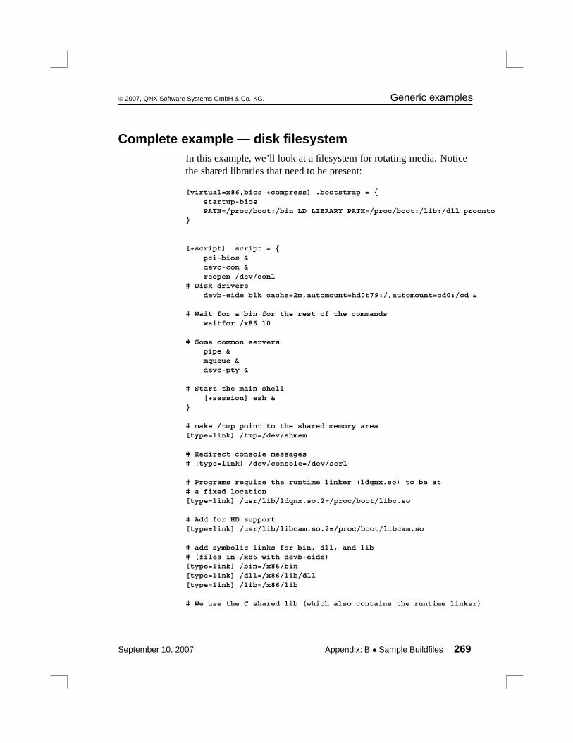
© 2007, QNX Software Systems GmbH & Co. KG. Generic examples
Complete example — disk filesystemIn this example, we’ll look at a filesystem for rotating media. Noticethe shared libraries that need to be present:
[virtual=x86,bios +compress] .bootstrap = {startup-biosPATH=/proc/boot:/bin LD_LIBRARY_PATH=/proc/boot:/lib:/dll procnto
}
[+script] .script = {pci-bios &devc-con &reopen /dev/con1
# Disk driversdevb-eide blk cache=2m,automount=hd0t79:/,automount=cd0:/cd &
# Wait for a bin for the rest of the commandswaitfor /x86 10
# Some common serverspipe &mqueue &devc-pty &
# Start the main shell[+session] esh &
}
# make /tmp point to the shared memory area[type=link] /tmp=/dev/shmem
# Redirect console messages# [type=link] /dev/console=/dev/ser1
# Programs require the runtime linker (ldqnx.so) to be at# a fixed location[type=link] /usr/lib/ldqnx.so.2=/proc/boot/libc.so
# Add for HD support[type=link] /usr/lib/libcam.so.2=/proc/boot/libcam.so
# add symbolic links for bin, dll, and lib# (files in /x86 with devb-eide)[type=link] /bin=/x86/bin[type=link] /dll=/x86/lib/dll[type=link] /lib=/x86/lib
# We use the C shared lib (which also contains the runtime linker)
September 10, 2007 Appendix: B • Sample Buildfiles 269
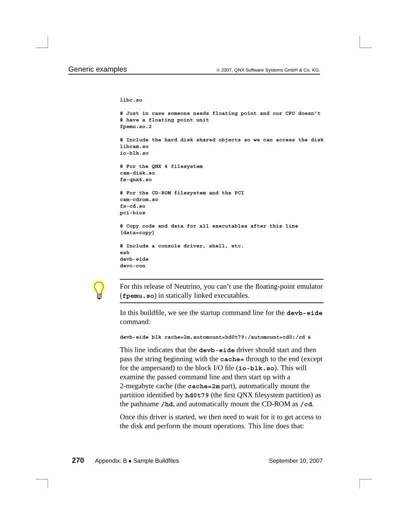
Generic examples © 2007, QNX Software Systems GmbH & Co. KG.
libc.so
# Just in case someone needs floating point and our CPU doesn’t# have a floating point unitfpemu.so.2
# Include the hard disk shared objects so we can access the disklibcam.soio-blk.so
# For the QNX 4 filesystemcam-disk.sofs-qnx4.so
# For the CD-ROM filesystem and the PCIcam-cdrom.sofs-cd.sopci-bios
# Copy code and data for all executables after this line[data=copy]
# Include a console driver, shell, etc.eshdevb-eidedevc-con
For this release of Neutrino, you can’t use the floating-point emulator(fpemu.so) in statically linked executables.
In this buildfile, we see the startup command line for the devb-eidecommand:
devb-eide blk cache=2m,automount=hd0t79:/automount=cd0:/cd &
This line indicates that the devb-eide driver should start and thenpass the string beginning with the cache= through to the end (exceptfor the ampersand) to the block I/O file (io-blk.so). This willexamine the passed command line and then start up with a2-megabyte cache (the cache=2m part), automatically mount thepartition identified by hd0t79 (the first QNX filesystem partition) asthe pathname /hd, and automatically mount the CD-ROM as /cd.
Once this driver is started, we then need to wait for it to get access tothe disk and perform the mount operations. This line does that:
270 Appendix: B • Sample Buildfiles September 10, 2007
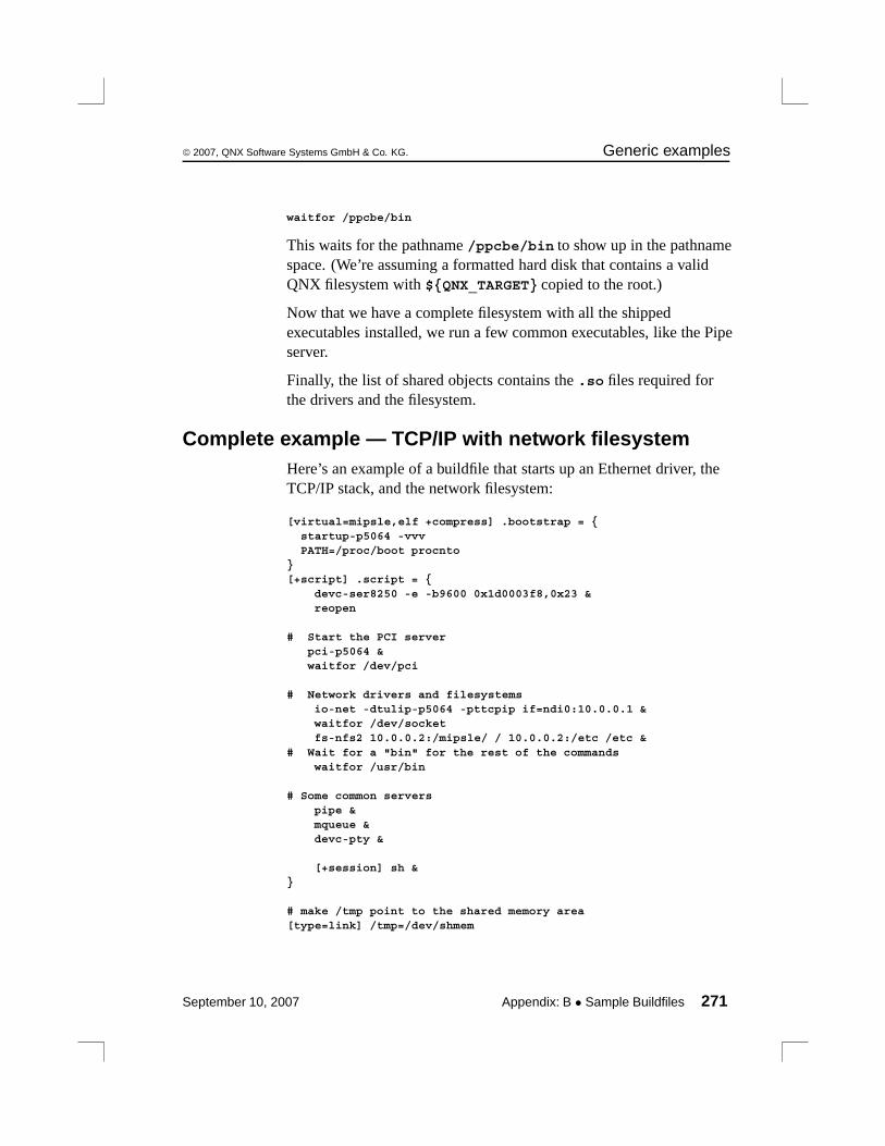
© 2007, QNX Software Systems GmbH & Co. KG. Generic examples
waitfor /ppcbe/bin
This waits for the pathname /ppcbe/bin to show up in the pathnamespace. (We’re assuming a formatted hard disk that contains a validQNX filesystem with ${QNX_TARGET} copied to the root.)
Now that we have a complete filesystem with all the shippedexecutables installed, we run a few common executables, like the Pipeserver.
Finally, the list of shared objects contains the .so files required forthe drivers and the filesystem.
Complete example — TCP/IP with network filesystemHere’s an example of a buildfile that starts up an Ethernet driver, theTCP/IP stack, and the network filesystem:
[virtual=mipsle,elf +compress] .bootstrap = {startup-p5064 -vvvPATH=/proc/boot procnto
}[+script] .script = {
devc-ser8250 -e -b9600 0x1d0003f8,0x23 &reopen
# Start the PCI serverpci-p5064 &waitfor /dev/pci
# Network drivers and filesystemsio-net -dtulip-p5064 -pttcpip if=ndi0:10.0.0.1 &waitfor /dev/socketfs-nfs2 10.0.0.2:/mipsle/ / 10.0.0.2:/etc /etc &
# Wait for a "bin" for the rest of the commandswaitfor /usr/bin
# Some common serverspipe &mqueue &devc-pty &
[+session] sh &}
# make /tmp point to the shared memory area[type=link] /tmp=/dev/shmem
September 10, 2007 Appendix: B • Sample Buildfiles 271
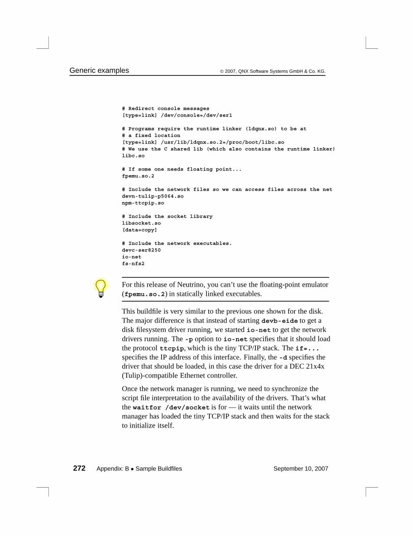
Generic examples © 2007, QNX Software Systems GmbH & Co. KG.
# Redirect console messages[type=link] /dev/console=/dev/ser1
# Programs require the runtime linker (ldqnx.so) to be at# a fixed location[type=link] /usr/lib/ldqnx.so.2=/proc/boot/libc.so# We use the C shared lib (which also contains the runtime linker)libc.so
# If some one needs floating point...fpemu.so.2
# Include the network files so we can access files across the netdevn-tulip-p5064.sonpm-ttcpip.so
# Include the socket librarylibsocket.so[data=copy]
# Include the network executables.devc-ser8250io-netfs-nfs2
For this release of Neutrino, you can’t use the floating-point emulator(fpemu.so.2) in statically linked executables.
This buildfile is very similar to the previous one shown for the disk.The major difference is that instead of starting devb-eide to get adisk filesystem driver running, we started io-net to get the networkdrivers running. The -p option to io-net specifies that it should loadthe protocol ttcpip, which is the tiny TCP/IP stack. The if=...specifies the IP address of this interface. Finally, the -d specifies thedriver that should be loaded, in this case the driver for a DEC 21x4x(Tulip)-compatible Ethernet controller.
Once the network manager is running, we need to synchronize thescript file interpretation to the availability of the drivers. That’s whatthe waitfor /dev/socket is for — it waits until the networkmanager has loaded the tiny TCP/IP stack and then waits for the stackto initialize itself.
272 Appendix: B • Sample Buildfiles September 10, 2007
© 2007, QNX Software Systems GmbH & Co. KG. Processor-specific notes
The next thing started is the NFS filesystem module, fs-nfs2, withoptions telling it that it should mount the filesystem present on10.0.0.2 in two different places: ${QNX_TARGET} should bemounted in /, and /etc should be mounted as /etc.
Since it may take some time to go over the network and establish themounting, we see another waitfor, this time ensuring that thefilesystem on the remote has been correctly mounted (here we assumethat the remote has a directory called ${QNX_TARGET}/mipsle/bin
— since we’ve mounted the remote’s ${QNX_TARGET} as /, thewaitfor is really waiting for mipsle/bin under the remote’s${QNX_TARGET} to show up).
Processor-specific notesIn this section, we’ll look at what’s different from the generic fileslisted above for each processor family. Since almost everything that’sprocessor- and platform-specific in Neutrino is contained in the kerneland startup programs, there’s very little change required to go from anx86 with standard BIOS to, for example, a PowerPC 800 evaluationboard.
Specifying the processorThe first obvious difference is that you must specify the processor thatthe buildfile is for. This is actually a simple change — in the[virtual=...] line, substitute the x86 specification with armle,mipsbe|le, ppcbe, or shle.
Examples
For this CPU: Use this attribute:
ARM (little-endian) [virtual=armle,binary]
MIPS (big-endian) [virtual=mipsbe,elf]
continued. . .
September 10, 2007 Appendix: B • Sample Buildfiles 273

Processor-specific notes © 2007, QNX Software Systems GmbH & Co. KG.
For this CPU: Use this attribute:
MIPS (little-endian) [virtual=mipsle,elf]
PPC (big-endian) [virtual=ppcbe,openbios]
SH-4 (little-endian) [virtual=shle,srec]
Specifying the startup programAnother difference is that the startup program is tailored not only forthe processor family, but also for the actual board the processor runson. If you’re not running an x86 with a standard BIOS, you shouldreplace the startup-bios command with one of the manystartup-* programs we supply.
To find out what startup programs we currently provide, please referto the following sources:
• the boards directory underbsp_working_dir/src/hardware/startup.
• QNX docs (BSP docs as well as startup-* entries in UtilitiesReference).
• the Community area of our website, www.qnx.com
Specifying the serial deviceThe examples listed previously provide support for the 8250 family ofserial chips. Some non-x86 platforms support the 8250 family aswell, but others have their own serial port chips.
For details on our current serial drivers, see:
• devc-* entries in the Utilities Reference.
• the Community area of our website, www.qnx.com
274 Appendix: B • Sample Buildfiles September 10, 2007

Appendix C
Packaging a Board SupportPackage
In this appendix. . .Structure of a BSP 277Packaging a BSP 278Documentation, including installation and release notes 279Testing your BSP 284
September 10, 2007 Appendix: C • Packaging a Board Support Package 275


© 2007, QNX Software Systems GmbH & Co. KG. Structure of a BSP
This appendix describes how to package a Board Support Package(BSP) to be compatible with the QNX Momentics development suite.
For information about licensing, see our website,http://www.qnx.com.
Structure of a BSPThe best way to start creating a BSP is to copy an existing EPL BSPfor a similar board. Depending on the features of a BSP, the directorystructure might look something like this:
bsp_working_dir
images prebuiltinstall src
devcdevnflashipl
startup
hardware
docs
usr
help
product
bsp_name
usr
dll
lib
usr
includebin sbin
binlibsbin
targetusr
dll
libbin sbin
binlibsbin
Directory structure of a BSP.
For more information about building a BSP, see the Working with aBSP chapter in this guide.
September 10, 2007 Appendix: C • Packaging a Board Support Package 277
Packaging a BSP © 2007, QNX Software Systems GmbH & Co. KG.
Don’t change the directory structure, or your BSP won’t work withthe IDE or our Makefiles. You can rename the directories for thedocumentation (bsp_name in the diagram above) and for the drivers,but don’t change the major directories.
The setupbsp command, which installs a BSP, overwrites alloccurrences of the roots.mk file, so don’t change these files.
Packaging a BSPWe provide a script, packagebsp, that packages your BSP so that itwill be compatible with QNX Momentics. This script uses zip tocreate an archive for all supported hosts.
You can use the command line or a configuration file to specify thefollowing inputs to the packagebsp script:
• location of shiplists (lists of the files you want to ship) for source,binary, prebuilt, documentation, and other files
• long and short forms of the BSP name
• location of the documentation
• location of the release notes
• source.xml, which the IDE uses for building the BSP anddisplaying information about it
• version of the BSP and the required version of QNX Neutrino
Depending on the options you specify, the script produces:
• an archive containing all the binaries that are relevant to the BSP,documentation (including installation and release notes), andsource code
Or:
• a similar archive, but without the source code
278 Appendix: C • Packaging a Board Support Package September 10, 2007

© 2007, QNX Software Systems GmbH & Co. KG. Documentation, including installation andrelease notes
For more details, see the entry for packagebsp in the UtilitiesReference.
If you package your BSP on a Windows host, the permissions for thefiles might not be correct if your users install it on a Linux or QNXNeutrino host. In this case, you should tell your users what ownershipand permissions you expect each file to have.
Documentation, including installation andrelease notesYou should include documentation with your BSP that describes howto use it. The QNX Momentics documentation includes sometemplates for BSP documentation including installation and releasenotes; see QNX BSP Documentation Templates in the online help.
You can provide your documentation in these forms:
• as an Eclipse plugin, to be displayed in the IDE’s help system
• as a directory of HTML and other files, to be displayed in a webbrowser, or in the Photon helpviewer on Neutrino systems.
To find the places where you need to fill in the templates, look formy-. Also watch for other instructions in italics.
Eclipse pluginsCopy the com.qnx.doc.bsp_doc_templates plugin to yourBSP’s documentation directory, and then modify the copy. Use thisform for the plugin’s directory name:
com.company_name.doc.bsp_manufacturer_board_version.timestamp
You need to specify the following pieces:
company_name A short form of your company name.
September 10, 2007 Appendix: C • Packaging a Board Support Package 279

Documentation, including installation and release notes © 2007, QNX Software Systems
GmbH & Co. KG.
manufacturer The name of the company that manufactures theboard.
board The short form of the board’s name.
version.timestamp
The version number (in the formmajor.minor.service_level) and timestamp of theplugin.
The name of the directory should match the plugin ID and version, asspecified in plugin.xml.
The plugin includes:
plugin.xml An XML file that Eclipse uses to identify theplugin. This file looks something like this:
<?xml version="1.0" encoding="UTF-8"?><?eclipse version="3.0"?><plugin id="com.qnx.doc.bsp_doc_templates"
name="QNX BSP Documentation Templates"version="1.0.0.20070814"provider-name="QNX Software Systems">
<extension point="org.eclipse.help.toc"><toc file="toc.xml" primary="true" />
<index path="index"/></extension><extension point="com.qnx.tools.ide.qde.ui.qdeSummary">
<summary file="fsummary.xml" /></extension>
</plugin>
Change this to reflect the name of your BSP, theplugin version, and the name of your company. Besure to change the plugin ID — that’s how Eclipseidentifies the plugin. For example:
<?xml version="1.0" encoding="UTF-8"?>
<?eclipse version="3.0"?><plugin id="com.my_company.doc.bsp_intel_DBPXA270DP"
name="Intel DBPXA270DP Board Support Package"
version="1.0.0.20071031"provider-name="My Company Name">
280 Appendix: C • Packaging a Board Support Package September 10, 2007
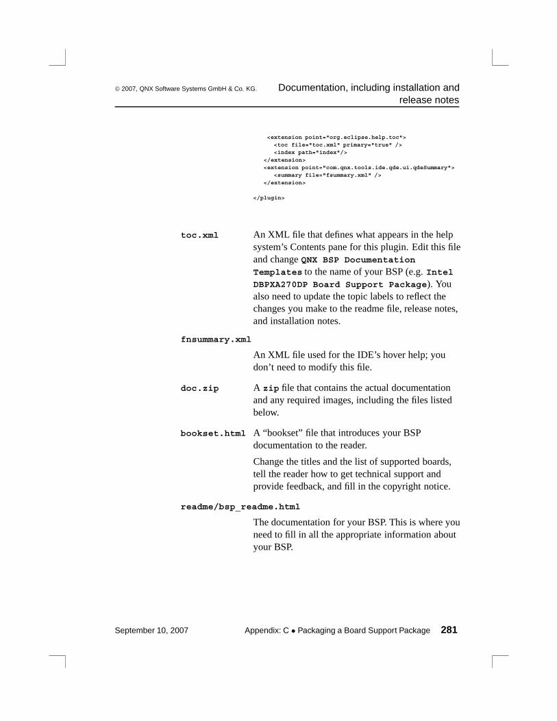
© 2007, QNX Software Systems GmbH & Co. KG. Documentation, including installation andrelease notes
<extension point="org.eclipse.help.toc"><toc file="toc.xml" primary="true" /><index path="index"/>
</extension><extension point="com.qnx.tools.ide.qde.ui.qdeSummary">
<summary file="fsummary.xml" />
</extension>
</plugin>
toc.xml An XML file that defines what appears in the helpsystem’s Contents pane for this plugin. Edit this fileand change QNX BSP Documentation
Templates to the name of your BSP (e.g. IntelDBPXA270DP Board Support Package). Youalso need to update the topic labels to reflect thechanges you make to the readme file, release notes,and installation notes.
fnsummary.xml
An XML file used for the IDE’s hover help; youdon’t need to modify this file.
doc.zip A zip file that contains the actual documentationand any required images, including the files listedbelow.
bookset.html A “bookset” file that introduces your BSPdocumentation to the reader.
Change the titles and the list of supported boards,tell the reader how to get technical support andprovide feedback, and fill in the copyright notice.
readme/bsp_readme.html
The documentation for your BSP. This is where youneed to fill in all the appropriate information aboutyour BSP.
September 10, 2007 Appendix: C • Packaging a Board Support Package 281

Documentation, including installation and release notes © 2007, QNX Software Systems
GmbH & Co. KG.
If you change the structure of this file (e.g. by adding or removingsections), be sure to make corresponding changes to the plugin’stoc.xml file, which the IDE’s help system uses to populate itsContents pane.
installation_note/installation_note.html
A generic installation note. You should fill in thetitle, the list of supported boards, the name of thezip file, technical-support information, and anyother relevant details.
release_notes/release_notes.html
Release notes. This template includes some issuesthat apply to all BSPs created with thepackagebsp script. Add any known issues withyour BSP to the list; if this version of the BSPaddresses any issues from previous releases,describe the fixes in the “Fixed issues” section.
When you run packagebsp, use the -p option or the doc_pluginentry in the configuration file to specify the paths of the plugins orJava Archive (JAR) files for your documentation.
For more information about plugins, see Eclipse: BuildingCommercial-Quality Plug-ins by Eric Clayberg and Dan Rubel(Addison-Wesley, 2006).
Photon helpviewer filesCopy the bsp_doc_templates directory and thebsp_doc_templates.toc file from$QNX_TARGET/usr/help/product to usr/help/product inyour BSP’s documentation directory, changing their names tosomething appropriate for your BSP, and then modify the copies.
The templates include:
282 Appendix: C • Packaging a Board Support Package September 10, 2007

© 2007, QNX Software Systems GmbH & Co. KG. Documentation, including installation andrelease notes
bsp_doc_templates.toc
A plain-text file that the Photon helpviewer uses to determinethe name of the documentation set. The template looks like this:
1|QNX BSP Documentation Templates|./bsp_doc_templates/bookset.html
Change this to reflect the name of your BSP. For example:
1|Intel DBPXA270DP Board Support Package (BSP)|./Intel_DBPXA270DP_bsp/bookset.html
bookset.html
A “bookset” file that introduces your BSP documentation to thereader.
Change the titles and the list of supported boards, tell the readerhow to get technical support and provide feedback, and fill inthe copyright notice.
readme.toc, installation_note.toc, release_notes.tocPlain-text files that the helpviewer uses to determine thename of your book, installation note, and release notes. Thereadme.toc file looks like this:
2|Read Me|./readme/bsp_readme.html
You don’t need to change these files.
readme/bsp_readme.html
The documentation for your BSP. This is where you need to fillin all the appropriate information about your BSP.
If you change the structure of this file (e.g. by adding or removingsections), be sure to make corresponding changes toreadme/book.toc, which the Photon helpviewer uses to populateits Topics pane. For more information, see the entry for helpviewerin the Utilities Reference.
September 10, 2007 Appendix: C • Packaging a Board Support Package 283
Testing your BSP © 2007, QNX Software Systems GmbH & Co. KG.
installation_note/installation_note.html
A generic installation note. You should fill in the title, the list ofsupported boards, the name of the zip file, technical-supportinformation, and any other relevant details.
release_notes/release_notes.html
Release notes. This template includes some issues that apply toall BSPs created with the packagebsp script. Add any knownissues with your BSP to the list; if this version of the BSPaddresses any issues from previous releases, describe the fixesin the “Fixed issues” section.
When you run packagebsp, use:
• the -n option or the doc_root entry in the configuration file tospecify the location of your BSP’s documentation
• the -q option or the docshiplist entry in the configuration fileto specify the location of the shiplist for the documentation
• the -k option or the relnote entry in the configuration file tospecify the location of the release notes. The script doesn’t add theinstallation note to the archive.
Testing your BSPThe packagebsp script will help you package everything that youneed to ship with your BSP, but you should test your BSP byinstalling and building it on another system. You should try to buildthe BSP on the command line and in the IDE. Where you’re going tobuild the BSP affects how you install it; for more information, see theinstallation notes.
For more information about building a BSP, see the Working with aBSP chapter in this guide.
284 Appendix: C • Packaging a Board Support Package September 10, 2007

Glossary
September 10, 2007 Glossary 285

© 2007, QNX Software Systems GmbH & Co. KG.
A20 gate
On x86-based systems, a hardware component that forces the A20address line on the bus to zero, regardless of the actual setting of theA20 address line on the processor. This component is in place tosupport legacy systems, but the QNX Neutrino OS doesn’t requireany such hardware. Note that some processors, such as the 386EX,have the A20 gate hardware built right into the processor itself — ourIPL will disable the A20 gate as soon as possible after startup.
adaptive
Scheduling algorithm whereby a thread’s priority is decayed by 1. Seealso FIFO, round robin, and sporadic.
adaptive partitioning
A method of dividing, in a flexible manner, CPU time, memory, fileresources, or kernel resources with some policy of minimumguaranteed usage.
asymmetric multiprocessing (AMP)
A multiprocessing system where a separate OS, or a separateinstantiation of the same OS, runs on each CPU.
atomic
Of or relating to atoms. :-)
In operating systems, this refers to the requirement that an operation,or sequence of operations, be considered indivisible. For example, athread may need to move a file position to a given location and readdata. These operations must be performed in an atomic manner;otherwise, another thread could preempt the original thread and movethe file position to a different location, thus causing the original threadto read data from the second thread’s position.
September 10, 2007 Glossary 287

© 2007, QNX Software Systems GmbH & Co. KG.
attributes structure
Structure containing information used on a per-resource basis (asopposed to the OCB, which is used on a per-open basis).
This structure is also known as a handle. The structure definition isfixed (iofunc_attr_t), but may be extended. See also mountstructure.
bank-switched
A term indicating that a certain memory component (usually thedevice holding an image) isn’t entirely addressable by the processor.In this case, a hardware component manifests a small portion (or“window”) of the device onto the processor’s address bus. Specialcommands have to be issued to the hardware to move the window todifferent locations in the device. See also linearly mapped.
base layer calls
Convenient set of library calls for writing resource managers. Thesecalls all start with resmgr_*(). Note that while some base layer callsare unavoidable (e.g. resmgr_pathname_attach()), we recommendthat you use the POSIX layer calls where possible.
BIOS/ROM Monitor extension signature
A certain sequence of bytes indicating to the BIOS or ROM Monitorthat the device is to be considered an “extension” to the BIOS orROM Monitor — control is to be transferred to the device by theBIOS or ROM Monitor, with the expectation that the device willperform additional initializations.
On the x86 architecture, the two bytes 0x55 and 0xAA must be present(in that order) as the first two bytes in the device, with control beingtransferred to offset 0x0003.
block-integral
The requirement that data be transferred such that individual structurecomponents are transferred in their entirety — no partial structurecomponent transfers are allowed.
288 Glossary September 10, 2007
© 2007, QNX Software Systems GmbH & Co. KG.
In a resource manager, directory data must be returned to a client asblock-integral data. This means that only complete struct dirent
structures can be returned — it’s inappropriate to return partialstructures, assuming that the next _IO_READ request will “pick up”where the previous one left off.
bootable
An image can be either bootable or nonbootable. A bootable image isone that contains the startup code that the IPL can transfer control to.
bootfile
The part of an OS image that runs the startup code and the Neutrinomicrokernel.
bound multiprocessing (BMP)
A multiprocessing system where a single instantiation of an OSmanages all CPUs simultaneously, but you can lock individualapplications or threads to a specific CPU.
budget
In sporadic scheduling, the amount of time a thread is permitted toexecute at its normal priority before being dropped to its low priority.
buildfile
A text file containing instructions for mkifs specifying the contentsand other details of an image, or for mkefs specifying the contentsand other details of an embedded filesystem image.
canonical mode
Also called edited mode or “cooked” mode. In this mode thecharacter device library performs line-editing operations on eachreceived character. Only when a line is “completely entered” —typically when a carriage return (CR) is received — will the line ofdata be made available to application processes. Contrast raw mode.
September 10, 2007 Glossary 289
© 2007, QNX Software Systems GmbH & Co. KG.
channel
A kernel object used with message passing.
In QNX Neutrino, message passing is directed towards a connection(made to a channel); threads can receive messages from channels. Athread that wishes to receive messages creates a channel (usingChannelCreate()), and then receives messages from that channel(using MsgReceive()). Another thread that wishes to send a messageto the first thread must make a connection to that channel by“attaching” to the channel (using ConnectAttach()) and then sendingdata (using MsgSend()).
CIFS
Common Internet File System (aka SMB) — a protocol that allows aclient workstation to perform transparent file access over a network toa Windows 95/98/NT server. Client file access calls are converted toCIFS protocol requests and are sent to the server over the network.The server receives the request, performs the actual filesystemoperation, and sends a response back to the client.
CIS
Card Information Structure — a data block that maintains informationabout flash configuration. The CIS description includes the types ofmemory devices in the regions, the physical geometry of thesedevices, and the partitions located on the flash.
combine message
A resource manager message that consists of two or more messages.The messages are constructed as combine messages by the client’s Clibrary (e.g. stat(), readblock()), and then handled as individualmessages by the resource manager.
The purpose of combine messages is to conserve network bandwidthand/or to provide support for atomic operations. See also connectmessage and I/O message.
290 Glossary September 10, 2007

© 2007, QNX Software Systems GmbH & Co. KG.
connect message
In a resource manager, a message issued by the client to perform anoperation based on a pathname (e.g. an io_open message).Depending on the type of connect message sent, a context block (seeOCB) may be associated with the request and will be passed tosubsequent I/O messages. See also combine message and I/Omessage.
connection
A kernel object used with message passing.
Connections are created by client threads to “connect” to the channelsmade available by servers. Once connections are established, clientscan MsgSendv() messages over them. If a number of threads in aprocess all attach to the same channel, then the one connection isshared among all the threads. Channels and connections are identifiedwithin a process by a small integer.
The key thing to note is that connections and file descriptors (FD) areone and the same object. See also channel and FD.
context
Information retained between invocations of functionality.
When using a resource manager, the client sets up an association orcontext within the resource manager by issuing an open() call andgetting back a file descriptor. The resource manager is responsible forstoring the information required by the context (see OCB). When theclient issues further file-descriptor based messages, the resourcemanager uses the OCB to determine the context for interpretation ofthe client’s messages.
cooked mode
See canonical mode.
September 10, 2007 Glossary 291
© 2007, QNX Software Systems GmbH & Co. KG.
core dump
A file describing the state of a process that terminated abnormally.
critical section
A code passage that must be executed “serially” (i.e. by only onethread at a time). The simplest from of critical section enforcement isvia a mutex.
deadlock
A condition in which one or more threads are unable to continue dueto resource contention. A common form of deadlock can occur whenone thread sends a message to another, while the other thread sends amessage to the first. Both threads are now waiting for each other toreply to the message. Deadlock can be avoided by good designpractices or massive kludges — we recommend the good designapproach.
device driver
A process that allows the OS and application programs to make use ofthe underlying hardware in a generic way (e.g. a disk drive, a networkinterface). Unlike OSs that require device drivers to be tightly boundinto the OS itself, device drivers for QNX Neutrino are standardprocesses that can be started and stopped dynamically. As a result,adding device drivers doesn’t affect any other part of the OS —drivers can be developed and debugged like any other application.Also, device drivers are in their own protected address space, so a bugin a device driver won’t cause the entire OS to shut down.
discrete (or traditional) multiprocessor system
A system that has separate physical processors hooked up inmultiprocessing mode over a board-level bus.
DNS
Domain Name Service — an Internet protocol used to convert ASCIIdomain names into IP addresses. In QNX native networking, dns isone of Qnet’s builtin resolvers.
292 Glossary September 10, 2007
© 2007, QNX Software Systems GmbH & Co. KG.
dynamic bootfile
An OS image built on the fly. Contrast static bootfile.
dynamic linking
The process whereby you link your modules in such a way that theProcess Manager will link them to the library modules before yourprogram runs. The word “dynamic” here means that the associationbetween your program and the library modules that it uses is done atload time, not at linktime. Contrast static linking. See also runtimeloading.
edge-sensitive
One of two ways in which a PIC (Programmable Interrupt Controller)can be programmed to respond to interrupts. In edge-sensitive mode,the interrupt is “noticed” upon a transition to/from the rising/fallingedge of a pulse. Contrast level-sensitive.
edited mode
See canonical mode.
EOI
End Of Interrupt — a command that the OS sends to the PIC afterprocessing all Interrupt Service Routines (ISR) for that particularinterrupt source so that the PIC can reset the processor’s In ServiceRegister. See also PIC and ISR.
EPROM
Erasable Programmable Read-Only Memory — a memorytechnology that allows the device to be programmed (typically withhigher-than-operating voltages, e.g. 12V), with the characteristic thatany bit (or bits) may be individually programmed from a 1 state to a 0state. To change a bit from a 0 state into a 1 state can only beaccomplished by erasing the entire device, setting all of the bits to a 1state. Erasing is accomplished by shining an ultraviolet light throughthe erase window of the device for a fixed period of time (typically
September 10, 2007 Glossary 293
© 2007, QNX Software Systems GmbH & Co. KG.
10-20 minutes). The device is further characterized by having alimited number of erase cycles (typically 10e5 - 10e6). Contrast flashand RAM.
event
A notification scheme used to inform a thread that a particularcondition has occurred. Events can be signals or pulses in the generalcase; they can also be unblocking events or interrupt events in thecase of kernel timeouts and interrupt service routines. An event isdelivered by a thread, a timer, the kernel, or an interrupt serviceroutine when appropriate to the requestor of the event.
FD
File Descriptor — a client must open a file descriptor to a resourcemanager via the open() function call. The file descriptor then servesas a handle for the client to use in subsequent messages. Note that afile descriptor is the exact same object as a connection ID (coid,returned by ConnectAttach()).
FIFO
First In First Out — a scheduling algorithm whereby a thread is ableto consume CPU at its priority level without bounds. See alsoadaptive, round robin, and sporadic.
flash memory
A memory technology similar in characteristics to EPROM memory,with the exception that erasing is performed electrically instead of viaultraviolet light, and, depending upon the organization of the flashmemory device, erasing may be accomplished in blocks (typically64k bytes at a time) instead of the entire device. Contrast EPROMand RAM.
FQNN
Fully Qualified NodeName — a unique name that identifies a QNXNeutrino node on a network. The FQNN consists of the nodenameplus the node domain tacked together.
294 Glossary September 10, 2007
© 2007, QNX Software Systems GmbH & Co. KG.
garbage collection
Aka space reclamation, the process whereby a filesystem managerrecovers the space occupied by deleted files and directories.
HA
High Availability — in telecommunications and other industries, HAdescribes a system’s ability to remain up and running withoutinterruption for extended periods of time.
handle
A pointer that the resource manager base library binds to thepathname registered via resmgr_attach(). This handle is typicallyused to associate some kind of per-device information. Note that ifyou use the iofunc_*() POSIX layer calls, you must use a particulartype of handle — in this case called an attributes structure.
hard thread affinity
A user-specified binding of a thread to a set of processors, done bymeans of a runmask. Contrast soft thread affinity.
image
In the context of embedded QNX Neutrino systems, an “image” canmean either a structure that contains files (i.e. an OS image) or astructure that can be used in a read-only, read/write, orread/write/reclaim FFS-2-compatible filesystem (i.e. a flashfilesystem image).
inherit mask
A bitmask that specifies which processors a thread’s children can runon. Contrast runmask.
interrupt
An event (usually caused by hardware) that interrupts whatever theprocessor was doing and asks it do something else. The hardware willgenerate an interrupt whenever it has reached some state wheresoftware intervention is required.
September 10, 2007 Glossary 295
© 2007, QNX Software Systems GmbH & Co. KG.
interrupt handler
See ISR.
interrupt latency
The amount of elapsed time between the generation of a hardwareinterrupt and the first instruction executed by the relevant interruptservice routine. Also designated as “Til”. Contrast schedulinglatency.
interrupt service routine
See ISR.
interrupt service thread
A thread that is responsible for performing thread-level servicing ofan interrupt.
Since an ISR can call only a very limited number of functions, andsince the amount of time spent in an ISR should be kept to aminimum, generally the bulk of the interrupt servicing work shouldbe done by a thread. The thread attaches the interrupt (viaInterruptAttach() or InterruptAttachEvent()) and then blocks (viaInterruptWait()), waiting for the ISR to tell it to do something (byreturning an event of type SIGEV_INTR). To aid in minimizingscheduling latency, the interrupt service thread should raise itspriority appropriately.
I/O message
A message that relies on an existing binding between the client andthe resource manager. For example, an _IO_READ message dependson the client’s having previously established an association (orcontext) with the resource manager by issuing an open() and gettingback a file descriptor. See also connect message, context, combinemessage, and message.
296 Glossary September 10, 2007

© 2007, QNX Software Systems GmbH & Co. KG.
I/O privileges
A particular right, that, if enabled for a given thread, allows the threadto perform I/O instructions (such as the x86 assembler in and out
instructions). By default, I/O privileges are disabled, because aprogram with it enabled can wreak havoc on a system. To enable I/Oprivileges, the thread must be running as root, and call ThreadCtl().
IPC
Interprocess Communication — the ability for two processes (orthreads) to communicate. QNX Neutrino offers several forms of IPC,most notably native messaging (synchronous, client/serverrelationship), POSIX message queues and pipes (asynchronous), aswell as signals.
IPL
Initial Program Loader — the software component that either takescontrol at the processor’s reset vector (e.g. location 0xFFFFFFF0 onthe x86), or is a BIOS extension. This component is responsible forsetting up the machine into a usable state, such that the startupprogram can then perform further initializations. The IPL is written inassembler and C. See also BIOS extension signature and startupcode.
IRQ
Interrupt Request — a hardware request line asserted by a peripheralto indicate that it requires servicing by software. The IRQ is handledby the PIC, which then interrupts the processor, usually causing theprocessor to execute an Interrupt Service Routine (ISR).
ISR
Interrupt Service Routine — a routine responsible for servicinghardware (e.g. reading and/or writing some device ports), forupdating some data structures shared between the ISR and thethread(s) running in the application, and for signalling the thread thatsome kind of event has occurred.
September 10, 2007 Glossary 297
© 2007, QNX Software Systems GmbH & Co. KG.
kernel
See microkernel.
level-sensitive
One of two ways in which a PIC (Programmable Interrupt Controller)can be programmed to respond to interrupts. If the PIC is operating inlevel-sensitive mode, the IRQ is considered active whenever thecorresponding hardware line is active. Contrast edge-sensitive.
linearly mapped
A term indicating that a certain memory component is entirelyaddressable by the processor. Contrast bank-switched.
message
A parcel of bytes passed from one process to another. The OSattaches no special meaning to the content of a message — the data ina message has meaning for the sender of the message and for itsreceiver, but for no one else.
Message passing not only allows processes to pass data to each other,but also provides a means of synchronizing the execution of severalprocesses. As they send, receive, and reply to messages, processesundergo various “changes of state” that affect when, and for howlong, they may run.
microkernel
A part of the operating system that provides the minimal servicesused by a team of optional cooperating processes, which in turnprovide the higher-level OS functionality. The microkernel itself lacksfilesystems and many other services normally expected of an OS;those services are provided by optional processes.
mount structure
An optional, well-defined data structure (of type iofunc_mount_t)within an iofunc_*() structure, which contains information used on a
298 Glossary September 10, 2007
© 2007, QNX Software Systems GmbH & Co. KG.
per-mountpoint basis (generally used only for filesystem resourcemanagers). See also attributes structure and OCB.
mountpoint
The location in the pathname space where a resource manager has“registered” itself. For example, the serial port resource managerregisters mountpoints for each serial device (/dev/ser1,/dev/ser2, etc.), and a CD-ROM filesystem may register a singlemountpoint of /cdrom.
multicore system
A chip that has one physical processor with multiple CPUsinterconnected over a chip-level bus.
mutex
Mutual exclusion lock, a simple synchronization service used toensure exclusive access to data shared between threads. It is typicallyacquired (pthread_mutex_lock()) and released(pthread_mutex_unlock()) around the code that accesses the shareddata (usually a critical section). See also critical section.
name resolution
In a QNX Neutrino network, the process by which the Qnet networkmanager converts an FQNN to a list of destination addresses that thetransport layer knows how to get to.
name resolver
Program code that attempts to convert an FQNN to a destinationaddress.
NDP
Node Discovery Protocol — proprietary QNX Software Systemsprotocol for broadcasting name resolution requests on a QNXNeutrino LAN.
September 10, 2007 Glossary 299
© 2007, QNX Software Systems GmbH & Co. KG.
network directory
A directory in the pathname space that’s implemented by the Qnetnetwork manager.
Neutrino
Name of an OS developed by QNX Software Systems.
NFS
Network FileSystem — a TCP/IP application that lets you graftremote filesystems (or portions of them) onto your local namespace.Directories on the remote systems appear as part of your localfilesystem and all the utilities you use for listing and managing files(e.g. ls, cp, mv) operate on the remote files exactly as they do onyour local files.
NMI
Nonmaskable Interrupt — an interrupt that can’t be masked by theprocessor. We don’t recommend using an NMI!
Node Discovery Protocol
See NDP.
node domain
A character string that the Qnet network manager tacks onto thenodename to form an FQNN.
nodename
A unique name consisting of a character string that identifies a nodeon a network.
nonbootable
A nonbootable OS image is usually provided for larger embeddedsystems or for small embedded systems where a separate,configuration-dependent setup may be required. Think of it as asecond “filesystem” that has some additional files on it. Since it’s
300 Glossary September 10, 2007
© 2007, QNX Software Systems GmbH & Co. KG.
nonbootable, it typically won’t contain the OS, startup file, etc.Contrast bootable.
OCB
Open Control Block (or Open Context Block) — a block of dataestablished by a resource manager during its handling of the client’sopen() function. This context block is bound by the resource managerto this particular request, and is then automatically passed to allsubsequent I/O functions generated by the client on the file descriptorreturned by the client’s open().
package filesystem
A virtual filesystem manager that presents a customized view of a setof files and directories to a client. The “real” files are present on somemedium; the package filesystem presents a virtual view of selectedfiles to the client.
partition
A division of CPU time, memory, file resources, or kernel resourceswith some policy of minimum guaranteed usage.
pathname prefix
See mountpoint.
pathname space mapping
The process whereby the Process Manager maintains an associationbetween resource managers and entries in the pathname space.
persistent
When applied to storage media, the ability for the medium to retaininformation across a power-cycle. For example, a hard disk is apersistent storage medium, whereas a ramdisk is not, because the datais lost when power is lost.
September 10, 2007 Glossary 301
© 2007, QNX Software Systems GmbH & Co. KG.
Photon microGUI
The proprietary graphical user interface built by QNX SoftwareSystems.
PIC
Programmable Interrupt Controller — hardware component thathandles IRQs. See also edge-sensitive, level-sensitive, and ISR.
PID
Process ID. Also often pid (e.g. as an argument in a function call).
POSIX
An IEEE/ISO standard. The term is an acronym (of sorts) for PortableOperating System Interface — the “X” alludes to “UNIX”, on whichthe interface is based.
POSIX layer calls
Convenient set of library calls for writing resource managers. ThePOSIX layer calls can handle even more of the common-casemessages and functions than the base layer calls. These calls areidentified by the iofunc_*() prefix. In order to use these (and westrongly recommend that you do), you must also use the well-definedPOSIX-layer attributes (iofunc_attr_t), OCB (iofunc_ocb_t),and (optionally) mount (iofunc_mount_t) structures.
preemption
The act of suspending the execution of one thread and starting (orresuming) another. The suspended thread is said to have been“preempted” by the new thread. Whenever a lower-priority thread isactively consuming the CPU, and a higher-priority thread becomesREADY, the lower-priority thread is immediately preempted by thehigher-priority thread.
302 Glossary September 10, 2007
© 2007, QNX Software Systems GmbH & Co. KG.
prefix tree
The internal representation used by the Process Manager to store thepathname table.
priority inheritance
The characteristic of a thread that causes its priority to be raised orlowered to that of the thread that sent it a message. Also used withmutexes. Priority inheritance is a method used to prevent priorityinversion.
priority inversion
A condition that can occur when a low-priority thread consumes CPUat a higher priority than it should. This can be caused by notsupporting priority inheritance, such that when the lower-prioritythread sends a message to a higher-priority thread, the higher-prioritythread consumes CPU on behalf of the lower-priority thread. This issolved by having the higher-priority thread inherit the priority of thethread on whose behalf it’s working.
process
A nonschedulable entity, which defines the address space and a fewdata areas. A process must have at least one thread running in it —this thread is then called the first thread.
process group
A collection of processes that permits the signalling of relatedprocesses. Each process in the system is a member of a process groupidentified by a process group ID. A newly created process joins theprocess group of its creator.
process group ID
The unique identifier representing a process group during its lifetime.A process group ID is a positive integer. The system may reuse aprocess group ID after the process group dies.
September 10, 2007 Glossary 303
© 2007, QNX Software Systems GmbH & Co. KG.
process group leader
A process whose ID is the same as its process group ID.
process ID (PID)
The unique identifier representing a process. A PID is a positiveinteger. The system may reuse a process ID after the process dies,provided no existing process group has the same ID. Only the ProcessManager can have a process ID of 1.
pty
Pseudo-TTY — a character-based device that has two “ends”: amaster end and a slave end. Data written to the master end shows upon the slave end, and vice versa. These devices are typically used tointerface between a program that expects a character device andanother program that wishes to use that device (e.g. the shell and thetelnet daemon process, used for logging in to a system over theInternet).
pulses
In addition to the synchronous Send/Receive/Reply services, QNXNeutrino also supports fixed-size, nonblocking messages known aspulses. These carry a small payload (four bytes of data plus a singlebyte code). A pulse is also one form of event that can be returnedfrom an ISR or a timer. See MsgDeliverEvent() for more information.
Qnet
The native network manager in QNX Neutrino.
QoS
Quality of Service — a policy (e.g. loadbalance) used to connectnodes in a network in order to ensure highly dependable transmission.QoS is an issue that often arises in high-availability (HA) networks aswell as realtime control systems.
304 Glossary September 10, 2007
© 2007, QNX Software Systems GmbH & Co. KG.
RAM
Random Access Memory — a memory technology characterized bythe ability to read and write any location in the device withoutlimitation. Contrast flash and EPROM.
raw mode
In raw input mode, the character device library performs no editing onreceived characters. This reduces the processing done on eachcharacter to a minimum and provides the highest performanceinterface for reading data. Also, raw mode is used with devices thattypically generate binary data — you don’t want any translations ofthe raw binary stream between the device and the application.Contrast canonical mode.
replenishment
In sporadic scheduling, the period of time during which a thread isallowed to consume its execution budget.
reset vector
The address at which the processor begins executing instructions afterthe processor’s reset line has been activated. On the x86, for example,this is the address 0xFFFFFFF0.
resource manager
A user-level server program that accepts messages from otherprograms and, optionally, communicates with hardware. QNXNeutrino resource managers are responsible for presenting aninterface to various types of devices, whether actual (e.g. serial ports,parallel ports, network cards, disk drives) or virtual (e.g. /dev/null,a network filesystem, and pseudo-ttys).
In other operating systems, this functionality is traditionallyassociated with device drivers. But unlike device drivers, QNXNeutrino resource managers don’t require any special arrangementswith the kernel. In fact, a resource manager looks just like any otheruser-level program. See also device driver.
September 10, 2007 Glossary 305

© 2007, QNX Software Systems GmbH & Co. KG.
RMA
Rate Monotonic Analysis — a set of methods used to specify,analyze, and predict the timing behavior of realtime systems.
round robin
Scheduling algorithm whereby a thread is given a certain period oftime to run. Should the thread consume CPU for the entire period ofits timeslice, the thread will be placed at the end of the ready queuefor its priority, and the next available thread will be made READY. Ifa thread is the only thread READY at its priority level, it will be ableto consume CPU again immediately. See also adaptive, FIFO, andsporadic.
runmask
A bitmask that indicates which processors a thread can run on.Contrast inherit mask.
runtime loading
The process whereby a program decides while it’s actually runningthat it wishes to load a particular function from a library. Contraststatic linking.
scheduling latency
The amount of time that elapses between the point when one threadmakes another thread READY and when the other thread actually getssome CPU time. Note that this latency is almost always at the controlof the system designer.
Also designated as “Tsl”. Contrast interrupt latency.
session
A collection of process groups established for job control purposes.Each process group is a member of a session. A process belongs tothe session that its process group belongs to. A newly created processjoins the session of its creator. A process can alter its session
306 Glossary September 10, 2007
© 2007, QNX Software Systems GmbH & Co. KG.
membership via setsid(). A session can contain multiple processgroups.
session leader
A process whose death causes all processes within its process groupto receive a SIGHUP signal.
soft thread affinity
The scheme whereby the microkernel tries to dispatch a thread to theprocessor where it last ran, in an attempt to reduce thread migrationfrom one processor to another, which can affect cache performance.Contrast hard thread affinity.
software interrupts
Similar to a hardware interrupt (see interrupt), except that the sourceof the interrupt is software.
sporadic
Scheduling algorithm whereby a thread’s priority can oscillatedynamically between a “foreground” or normal priority and a“background” or low priority. A thread is given an execution budgetof time to be consumed within a certain replenishment period. Seealso adaptive, FIFO, and round robin.
startup code
The software component that gains control after the IPL code hasperformed the minimum necessary amount of initialization. Aftergathering information about the system, the startup code transferscontrol to the OS.
static bootfile
An image created at one time and then transmitted whenever a nodeboots. Contrast dynamic bootfile.
September 10, 2007 Glossary 307

© 2007, QNX Software Systems GmbH & Co. KG.
static linking
The process whereby you combine your modules with the modulesfrom the library to form a single executable that’s entirelyself-contained. The word “static” implies that it’s not going to change— all the required modules are already combined into one.
symmetric multiprocessing (SMP)
A multiprocessor system where a single instantiation of an OSmanages all CPUs simultaneously, and applications can float to any ofthem.
system page area
An area in the kernel that is filled by the startup code and containsinformation about the system (number of bytes of memory, locationof serial ports, etc.) This is also called the SYSPAGE area.
thread
The schedulable entity under QNX Neutrino. A thread is a flow ofexecution; it exists within the context of a process.
timer
A kernel object used in conjunction with time-based functions. Atimer is created via timer_create() and armed via timer_settime(). Atimer can then deliver an event, either periodically or on a one-shotbasis.
timeslice
A period of time assigned to a round-robin or adaptive scheduledthread. This period of time is small (on the order of tens ofmilliseconds); the actual value shouldn’t be relied upon by anyprogram (it’s considered bad design).
308 Glossary September 10, 2007

Index
!
/dev/shmem 13/tmp, creating on a RAM-disk 266<startup.h> 147
A
A20 203, 255adaptive partitioning 59add_cache() 178add_callout_array() 179add_callout() 178add_interrupt_array() 162, 179,
193add_interrupt() 179add_ram() 179, 194add_string() 162, 179add_typed_string() 162, 179alloc_qtime() 180alloc_ram() 180ARM 165, 172, 192–194, 200, 273as_add_containing() 180as_add() 180
AS_ATTR_CACHABLE 141AS_ATTR_CONTINUED 141AS_ATTR_KIDS 141AS_ATTR_READABLE 141AS_ATTR_WRITABLE 141as_default() 181as_find_containing() 181as_find() 181as_info2off() 182AS_NULL_OFF 140as_off2info() 182AS_PRIORITY_DEFAULT 140as_set_checker() 182as_set_priority() 182avoid_ram() 182
B
bank-switched See also imagedefined 91
BIOS 4, 5, 150, 204extension 96, 204if you don’t have one 274
September 10, 2007 Index 309
Index © 2007, QNX Software Systems GmbH & Co. KG.
block_size buildfile attribute62, 63
Board Support Packages See BSPsboot header 105bootfile 50BOOTP 96, 102bootstrap file (.bootstrap) 50,
58, 59bound multiprocessing (BMP) 58break_detect() 175bsp_working_dir 26BSPs
binary componentscommand line 33IDE 34
content 23, 25documentation 26, 279packaging 277proprietary style 23, 24simplified style 23source code 29
command line 30importing into the IDE 32
testing 284buildfile
attributes 50block_size 62, 63combining 56compress 60, 107CPU 58data 264filter 62, 64gid 56keeplinked 87max_size 62min_size 62module 59
newpath 54perms 56physical 59script 51search 53spare_blocks 62, 63type 266uid 56virtual 50, 59, 106, 273
complete examples of 263including lots of files in 57inline files 50, 55simple example of 49specifying a processor in 273syntax 50
Bus item (system page) 148
C
cache 150, 151, 154, 177CACHE_FLAG_CTRL_PHYS 155CACHE_FLAG_DATA 155CACHE_FLAG_INSTR 155CACHE_FLAG_NONCOHERENT
155CACHE_FLAG_NONISA 155CACHE_FLAG_SHARED 155CACHE_FLAG_SNOOPED 155CACHE_FLAG_SUBSET 155CACHE_FLAG_UNIFIED 155CACHE_FLAG_VIRTUAL 155CACHE_FLAG_WRITEBACK 155cacheattr 154calc_time_t() 183calloc_ram() 183
310 Index September 10, 2007

© 2007, QNX Software Systems GmbH & Co. KG. Index
CALLOUT_END 208callout_io_map_indirect() 183callout_memory_map_indirect()
183callout_register_data() 183CALLOUT_START 208callout area 161callouts 6, 8, 174
writing your own 205character I/O devices 16chip_access() 184chip_done() 184chip_read16() 185chip_read32() 185chip_read8() 185chip_write16() 185chip_write32() 185chip_write8() 185CIFS 81clock, external 256ClockAdjust() 158–160ClockCycles() 158ClockPeriod() 158, 160ClockTime() 159cold-start IPL 4, 97compress buildfile attribute 60,
107compressing/decompressing 64compression
methods, choosing 107mountpoint (.cmp) 67rules 67
config callout 169config() 176confname() 162control() 177conventions
typographical xviiicopy_memory() 185CPU_FLAG_FPU 151CPU_FLAG_MMU 151CPU buildfile attribute 58cpuinfo 157CPUs, number of on the
system 139custom engineering 252
D
data buildfile attribute 264debugging 82
hardware considerations 252symbol information,
providing 83versions of software 252
del_typed_string() 186design do’s and don’ts 259devf-generic 15, 40, 221devf-ram 14
template for new drivers 224,244
Device item (system page) 149disks, information about
detected 111display_char() 175dumpifs 60
E
enable_cache() 122EOI (End of Interrupt) 165
September 10, 2007 Index 311

Index © 2007, QNX Software Systems GmbH & Co. KG.
Ethernet 272extension signature 96
F
f3s_close() 230f3s_flash_t 228f3s_ident() 235f3s_init() 229f3s_open() 230, 233F3S_OPER_SOCKET 231F3S_OPER_WINDOW 231f3s_page() 230F3S_POWER_VCC 231F3S_POWER_VPP 231f3s_reset() 235f3s_service_t 228f3s_socket_option() 232, 233f3s_socket_syspage() 234f3s_start() 229f3s_status() 230f3s_sync() 239f3s_v2erase() 237f3s_v2islock() 240f3s_v2lock() 240f3s_v2read() 235f3s_v2resume() 238f3s_v2suspend() 237f3s_v2unlock() 241f3s_v2unlockall() 242f3s_v2write() 236falcon_init_l2_cache() 186falcon_init_raminfo() 186falcon_system_clock() 186field upgrades 253
files.bootstrap 50, 59inline 50, 55main.c 117
filesystemschoosing 11CIFS (Common Internet File
System)[fs-cifs] 79ISO-9660 CD-ROM
(fs-cd.so) 79Linux (fs-ext2.so) 79MS-DOS (fs-dos.so) 79NFS (Network File
System)[fs-nfs2] 79package (fs-pkg) 79QNX 4 (fs-qnx4.so) 79
filter buildfile attribute 62, 64find_startup_info() 186, 194find_typed_string() 187flags member 166flash 253
accessing compressed fileswithout decompressing64
erasing 40filesystem
customizing 221images 47, 61partitions 38, 40
logical layout of memorychips 254
transferring images to 73two independent sets of
devices 254flashcmp 64flashctl 40, 73
312 Index September 10, 2007

© 2007, QNX Software Systems GmbH & Co. KG. Index
floating-point emulator (fpemu.so),can’t use in statically linkedexecutables 270
fnsummary.xml 281fs-cd.so 79fs-cifs 79fs-dos.so 79fs-ext2.so 79fs-nfs2 79fs-pkg 79fs-qnx4.so 79ftruncate() 68
G
gid buildfile attribute 56glitch interrupts, beware of 257Global Descriptor Table
(GDT) 170Group item (system page) 148
H
handle_common_option() 187hardware
debuggers 82information about 142supported by Neutrino 11, 15,
16system design
considerations 251hwi_add_device() 188hwi_add_inputclk() 188hwi_add_irq() 188
hwi_add_location() 189hwi_add_nicaddr() 189hwi_add_rtc() 189hwi_alloc_item() 144, 145, 147,
189hwi_alloc_tag 190hwi_alloc_tag() 144, 145, 147hwi_find_as() 190hwi_find_item() 145, 146, 190hwi_find_tag() 191HWI_NULL_OFF 143, 145, 146hwi_off2tag() 146, 191HWI_TAG_INFO() 147, 148hwi_tag2off() 146, 191
I
IDT (Interrupt DescriptorTable) 165
image_download_8250() 93, 118,122
image_scan_ext() 123image_scan() 93, 118, 123image_setup_ext() 123image_setup() 93, 118, 123image_start_ext() 124image_start() 95, 118, 124images
bank-switched 91, 99sources of 92
bootable 47building 35, 47, 52combining multiple files 71compressing 60defined 47
September 10, 2007 Index 313

Index © 2007, QNX Software Systems GmbH & Co. KG.
determining which sharedlibraries to include 264
example of using an OS imageas a filesystem 48
format 5, 71linearly mapped 91listing contents of 60loading 97more than one in system 48nonbootable 48physical address 107signature 106transferring onto your
board 36transferring to flash 73
init_asinfo() 192init_cacheattr() 154, 192init_cpuinfo() 150, 154, 192init_hwinfo() 142, 192init_intrinfo() 162, 192init_mmu() 193init_pminfo() 193init_qtime_sa1100() 194init_qtime() 158, 194init_raminfo() 180, 183, 194init_smp() 139, 170, 195init_syspage_memory() 195init_system_private() 139, 188,
195Initial Program Loader See IPLinline files 50, 55int15_copy() 124Intel hex records 72Interrupt Descriptor Table
(IDT) 170interrupt system, information
about 162
InterruptAttach() 162, 169, 257InterruptAttachEvent() 169, 257InterruptMask() 168InterruptUnmask() 168INTR_CONFIG_FLAG_DISALLOWED
169INTR_CONFIG_FLAG_IPI 169INTR_CONFIG_FLAG_PREATTACH
169INTR_FLAG_CASCADE_IMPLICIT_EOI
167INTR_FLAG_CPU_FAULT 167INTR_FLAG_NMI 167INTR_GENFLAG_LOAD_CPUNUM
169INTR_GENFLAG_LOAD_INTRINFO
168INTR_GENFLAG_LOAD_INTRMASK
168INTR_GENFLAG_LOAD_SYSPAGE
168INTR_GENFLAG_NOGLITCH 169intrinfo area 162io 149IPI (Interprocess Interrupt) 173IPL 3, 37
code, structure of 117cold-start 4, 97customizing 103debugging 82
debug symbolinformation 84
responsibilities of 91types of 4warm-start 4, 96
IRQ7 and IRQ15, beware of 257ISA bus slots, external 255
314 Index September 10, 2007

© 2007, QNX Software Systems GmbH & Co. KG. Index
IVOR (Interrupt Vector OffsetRegister) 165
J
JTAGfield upgrades 253hardware debuggers 82
jtag_reserve_memory() 195
K
keeplinked buildfile attribute 87kernel callouts See calloutskprintf() 187, 196
L
ldqnx.so.2 264linearly mapped 98, See also image
defined 91recommended 101sources of 92
linker, runtime 264Linux filesystem 79ln 13location tag 149lseek() 65lstat() 65
M
machine type 107main() 135, 147, 222, 227mask() 176max_size buildfile attribute 62memory 149memory
linearly addressable 5planning for target system 252
min_size buildfile attribute 62MIPS 165, 172, 192–194, 200, 273MIPS_CPU_FLAG_128BIT 151MIPS_CPU_FLAG_64BIT 151MIPS_CPU_FLAG_L2_PAGE_CACHE_OPS
151MIPS_CPU_FLAG_MAX_PGSIZE_MASK
151MIPS_CPU_FLAG_NO_COUNT
151MIPS_CPU_FLAG_NO_WIRED
151MIPS_CPU_FLAG_PFNTOPSHIFT_MASK
151MIPS_CPU_FLAG_SUPERVISOR
151MIPS_CPU_FLAGS_MAX_PGSIZE_SHIFT
151mips41xx_set_clock_freqs() 196mkefs 47, 61
buildfile 61mkifs 47, 49, 52, 60, 263
version of 106MKIFS_PATH 52mkimage 71mkrec 71, 72mmap_device_memory() 160
September 10, 2007 Index 315
Index © 2007, QNX Software Systems GmbH & Co. KG.
module buildfile attribute 59Moore’s Law 69Motorola S records 72mountpoints
filesystem 75raw
transferring images toflash 73
N
networkboot 101drivers 77, 79filesystems 77, 80, 271media 15
newpath buildfile attribute 54NFS (Network Filesystem) 15, 81,
273NMI (Non-Maskable Interrupt) 258
O
O_TRUNC 68objdump 264openbios_init_raminfo() 196OS images See images
P
packagebsp 278Page Directory Tables 170
parallel portdoesn’t need an interrupt
line 258pathname delimiter in QNX
Momentics documentationxix
pcnet_reset() 196pdebug 82peripherals, choosing 252perms buildfile attribute 56Photon, in embedded systems xviiiphysical buildfile attribute 59PIC 256plugin.xml 280plugins, BSP documentation as 279poll_key() 175POSIX 61, 65, 68, 81, 265pound sign, in buildfiles 50power management 173, 178power() 178PPC 165, 171, 192–194, 200, 212,
273PPC_CPU_ALTIVEC 151PPC_CPU_DCBZ_NONCOHERENT
151PPC_CPU_EAR 151PPC_CPU_FPREGS 151PPC_CPU_HW_HT 151PPC_CPU_HW_POW 151PPC_CPU_SW_HT 151PPC_CPU_SW_TLBSYNC 151PPC_CPU_TLB_SHADOW 151PPC_CPU_XAEN 151ppc_dec_init_qtime() 198PPC_INTR_FLAG_400ALT 168PPC_INTR_FLAG_CI 168
316 Index September 10, 2007

© 2007, QNX Software Systems GmbH & Co. KG. Index
PPC_INTR_FLAG_SHORTVEC168
PPC/BE 165ppc400_pit_init_qtime() 196ppc405_set_clock_freqs() 197ppc600_set_clock_freqs() 197ppc700_init_l2_cache() 197ppc800_pit_init_qtime() 197ppc800_set_clock_freqs() 198print_byte() 124print_char() 124, 196print_long() 124print_sl() 125print_string() 125print_syspage() 198print_var() 125print_word() 125printf() 196PROCESSOR 53processors
families, supported 10number of on the system 139speed 251
procnto
memory pool, adding to 110optional modules, binding 59starting 3, 6, 51version, verifying 215
protected_mode() 125
Q
Qnet (QNX native networking) 15QNX Neutrino
running for the first time 41
qtime 158
R
RAM, using as a “disk” 13read() 65reboot() 177reclamation 63reopen 266reset vector 3, 10ROM
devices 101monitor 5
rtc_time() 199runtime linker 264
S
script buildfile attribute 51script file 9
on the target 58search buildfile attribute 53sendnto 37serial port 102
loader 102recommended on target
system 257support for multiple 257
setenv.sh script 24, 25setupbsp 23, 278SH 173, 193, 194, 200, 273shared libraries 263
which to include in animage 264
September 10, 2007 Index 317

Index © 2007, QNX Software Systems GmbH & Co. KG.
shared memory 13shell
running in background 265SMP 170, 195socket services 223, 229software debuggers 82spare_blocks buildfile attribute
62, 63startup 6
creating your own 136debugging 82
debug symbolinformation 86
library 178structure of 135transferring control to 103
STARTUP_HDR_FLAGS1_BIGENDIAN106
STARTUP_HDR_FLAGS1_COMPRESS_LZO106
STARTUP_HDR_FLAGS1_COMPRESS_NONE106
STARTUP_HDR_FLAGS1_COMPRESS_UCL107
STARTUP_HDR_FLAGS1_COMPRESS_ZLIB106
STARTUP_HDR_FLAGS1_VIRTUAL106
STARTUP_HDR_SIGNATURE 93startup_header 94
structure of 105use by IPL and startup 112
STARTUP_INFO_* 109startup_info_box 112startup_info_disk 111
startup_info_mem,startup_info_mem_extended
110startup_info_skip 110startup_info_time 111startup_info* structures 109startup_io_map() 201startup_io_unmap() 201startup_memory_map() 202startup_memory_unmap() 202stat() 65, 81SUPPORT_CMP_* 107SYSENTER/SYSEXIT 151SYSPAGE_ARM 138, 169syspage_entry 137, 154, 158SYSPAGE_MIPS 138, 169SYSPAGE_PPC 138, 169SYSPAGE_SH 169SYSPAGE_SH4 138SYSPAGE_X86 138, 169system page area 7, 133, 137
accessing data within 137fields in 138
T
TCP/IP 271temporary directory, creating on a
RAM-disk 266timer_load() 175timer_reload() 175timer_value() 175toc.xml 281truncation 68tulip_reset() 202
318 Index September 10, 2007

© 2007, QNX Software Systems GmbH & Co. KG. Index
type buildfile attribute 266typed_strings area 162typographical conventions xviii
U
uart_hex16 126uart_hex32 126uart_hex8 125uart_init 126uart_put 127uart_string 127uart32_hex16 128uart32_hex32 128uart32_hex8 127uart32_init 128uart32_put 129uart32_string 129uid buildfile attribute 56uncompress() 113, 116, 202union 169unmask() 176
V
video, displaying on 124, 125virtual buildfile attribute 50, 59,
106, 273
W
waitfor 81
warm-start IPL 4, 96working set, creating 34
X
X86_CPU_BSWAP 151X86_CPU_CMOV 151X86_CPU_CPUID 151X86_CPU_FXSR 151X86_CPU_INVLPG 151X86_CPU_MMX 151X86_CPU_MTRR 151X86_CPU_PAE 151X86_CPU_PGE 151X86_CPU_PSE 151X86_CPU_RDTSC 151X86_CPU_SEP 151X86_CPU_SIMD 151X86_CPU_WP 151x86_cpuid_string() 203x86_cputype() 203x86_enable_a20() 203x86_fputype() 204x86_init_pcbios() 204x86_pcbios_shadow_rom() 204x86_scanmem() 194, 204, 205x86-specific information 170XML files for BSP
documentation 280
Z
zip 23zombies, surfeit of 52
September 10, 2007 Index 319