qtu series - primemach.commazak is a single point of contact for any mazak-related service need,...
TRANSCRIPT
1 Product images are for illustration purposes only and may not be exact representations of the product. Mazak reserves the right to change product images and specifications at any time without notice.
QTU Series200 | 200M | 200MS | 200MY | 200MSY | 250 | 250M | 250MS | 250MY | 250MSY | 350 | 350M | 350MS | 350MY | 350MSY
2 Product images are for illustration purposes only and may not be exact representations of the product. Mazak reserves the right to change product images and specifications at any time without notice.
TABLE OF CONTENTS
TABLE OF CONTENTS
Introduction ........................................................................................3
Optimum Plus Service and Support ................................................ 4-5
Top 10 Advantages .............................................................................6
Structure ............................................................................................7
Headstock and Spindle.................................................................... 8-9
Servo Turret .......................................................................................10
Tailstock ............................................................................................11
Milling Option....................................................................................12
Y-Axis Option .....................................................................................13
Second Spindle Option ......................................................................14
Optional Equipment ..........................................................................15
Fast, Easy and Efficient Programming ........................................ 16-17
MAZATROL SmoothC Control ........................................................ 18-19
Mazak Automation Systems......................................................... 20-21
Mazak Digital Solutions............................................................... 22-23
Tooling System Schematics ......................................................... 24-29
Tool Interference Diagrams.......................................................... 30-39
External Dimensions.................................................................... 40-43
Machine Specifications ............................................................... 44-49
Spindle and Unit Rebuild ..................................................................50
Environmentally Friendly ...................................................................51
Mazak Technology + Technical Centers ....................................... 52-53
Financing ..........................................................................................54
Resources and Links .........................................................................55

3Product images are for illustration purposes only and may not be exact representations of the product. Mazak reserves the right to change product images and specifications at any time without notice.
INTRODUCTION
Built at the Mazak iSMART Factory in Florence, Kentucky, the simple but innovative compact QTU Series machines represent the next-generation of world-class CNC Turning Centers that deliver both high productivity and cost effectiveness.
MACHINE CONFIGURATIONS: • QTU-200 • QTU-200M • QTU-200MS • QTU-200MY • QTU-200MSY
• QTU-250 • QTU-250M • QTU-250MS • QTU-250MY • QTU-250MSY
• QTU-350 • QTU-350M • QTU-350MS • QTU-350MY • QTU-350MSY
M = turret with rotary milling S = second spindle Y = Y-axis off-centerline capability
QTU SERIES 200 | 200M | 200MS | 200MY | 200MSY 250 | 250M | 250MS | 250MY | 250MSY 350 | 350M | 350MS | 350MY | 350MSY
QTU-200

4 Product images are for illustration purposes only and may not be exact representations of the product. Mazak reserves the right to change product images and specifications at any time without notice.
OPTIMUM PLUS SERVICE AND SUPPORT
MAZAK OPTIMUM PLUSTo maximize machine tool investments, the Mazak Optimum Plus program represents a company-wide commitment to provide the best possible, most comprehensive support.
The Optimum Plus program encompasses Five Pillars — distinct, yet interrelated areas:• Single-source service• Technical support — machine and CNC• Parts support• Progressive Learning• Spindle and unit rebuild
Single-source serviceMazak is a single point of contact for any Mazak-related service need, whether it involves a machine, control, accessory or automation solution. This effective service approach helps customers maintain the highest possible level of productivity.
Benefits of Mazak’s single-source approach include: • Free technical phone support and software upgrades for the life of a Mazak machine• Software support that provides instantaneous diagnostic
services via remote real-time systems• Guaranteed phone response to any technical question within one hour via a 24/7 technical phone support system• More than 350 factory-trained Mazak service representatives and certified distributor personnel that can be at a customer’s site within 24 hours under most circumstances• Wide variety of services, including laser calibration to ISO, ANSI and JIS standards; ball bar qualification and analysis; preventive maintenance plans and programs; and vibration analysis and benchmarking
Technical support — machine and CNCComprehensive warranties on every Mazak machine tool component, including a two-year part warranty on CNC control components.
Technical support for machines and CNCs also includes:• Additional warranty coverage (available upon request)
THE MAZAK OPTIMUM PLUS PROGRAM ENABLES CUSTOMERS TO MAXIMIZE THE VALUE OF THEIR MAZAK PURCHASE.
5Product images are for illustration purposes only and may not be exact representations of the product. Mazak reserves the right to change product images and specifications at any time without notice.
OPTIMUM PLUS SERVICE AND SUPPORT
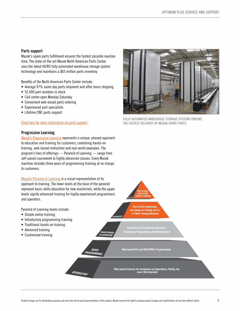
Parts supportMazak's spare parts fulfillment ensures the fastest possible reaction time. The state-of-the-art Mazak North American Parts Center uses the latest AS/RS fully automated warehouse storage system technology and maintains a $65 million parts inventory.
Benefits of the North American Parts Center include:• Average 97% same day parts shipment and after hours shipping • 52,000 part numbers in stock• Call center open Monday-Saturday• Convenient web-based parts ordering• Experienced part specialists• Lifetime CNC parts support
Click here for more information on parts support.
Progressive LearningMazak’s Progressive Learning represents a unique, phased approach to education and training for customers, combining hands-on training, web-based instruction and real-world examples. The program’s tiers of offerings — Pyramid of Learning — range from self-paced coursework to highly advanced classes. Every Mazak machine includes three years of programming training at no charge to customers.
Mazak’s Pyramid of Learning is a visual representation of its approach to training. The lower levels at the base of the pyramid represent basic skills education for new machinists, while the upper levels signify advanced training for highly experienced programmers and operators.
Pyramid of Learning levels include:• Simple online training• Introductory programming training• Traditional hands-on training• Advanced training• Customized training
User Groups and On-Site
Custom Training
PALLETECH Optimization and Hands-on Training (H.O.T.)
for Multi-Tasking Machines
Instructor Led Traditional Classroom
Training on Programming and Maintenance
Web-based Courses for Customers on Operations, Safety, etc. (over 450 tutorials)INTRODUCTORY
BASIC PROGRAMMING
TRADITIONALCLASSROOM
ADVANCED
ELITE
Web-based EIA and MAZATROL Programming
FULLY AUTOMATED WAREHOUSE STORAGE SYSTEMS ENSURE THE FASTEST DELIVERY OF MAZAK SPARE PARTS.

6 Product images are for illustration purposes only and may not be exact representations of the product. Mazak reserves the right to change product images and specifications at any time without notice.
TOP 10 ADVANTAGES
TOP 10 ADVANTAGES
While basic in their designs, QTU Series machines feature new and innovative technologies that bring high productivity, precision, performance and value to job shops as well as first and second tier manufacturing suppliers. The series provides the perfect balance of technology and minimized operational costs.
TOP 10 ADVANTAGES OF THE QTU SERIES
1. New design concept for a wide range of machine configurations up to 5-axis including C-axis, Y-axis and A-axis capability and single or double spindles.
2. Extremely rigid base with low center of gravity for stability and vibration dampening.
3. Proven advanced integral spindle motor/headstock technology ensures reliable, maintenance-free high performance.
4. High-precision C-axis delivers 360 degrees of programmable motion for processing flexibility.
5. Innovative servo turret expands for added tooling capacity.
6. NC servo-driven tailstock is fully programmable for simple and precise operation.
7. Large swing capacity minimizes interference.
8. MAZATROL SmoothC CNC further enhances overall performance.
9. Green, energy efficient and ergonomic features make for ease of use, environmentally friendly, low-maintenance operation.
10. Optional seamless automation integration increases uptime and lights-out production.

7Product images are for illustration purposes only and may not be exact representations of the product. Mazak reserves the right to change product images and specifications at any time without notice.
STRUCTURE
STRUCTURE
An innovative base design outfitted with the industry’s leading guideway system forms the perfect foundation for the outstanding performance of the QTU Series machines.
BASE New high-rigidity base/bed design ensures thermal stability and ample part capacity.
• Finite Element Method (FEM) yields maximum cooling and expansion control• Low center of gravity provides the foundation and durability for sustained heavy cutting • Bed lengths range from 20" (508 mm) to 40" (1,016 mm)• Hand scraped to ensure quality and high precision accuracy • Large 27.4" (696 mm) swing capacity for less interference• Maximum turning diameter of 16.25" (410 mm) on QTU-200/QTU-
250/QTU-350 and 13.5" (340 mm) on QTU-200/250/350M/MS/MSY• Rapid traverse rates of 1,181 ipm (30 m/min) in X axes and 1,417 ipm (36 m/min) in Z axes
ROLLER GUIDEWAY SYSTEM Mazak’s MX Hybrid Roller Guide System incorporates a special X-design that efficiently distributes load in four directions — radial (clockwise and counterclockwise), reverse radial and lateral.
MX Hybrid Roller Guide benefits:• Best combination of consistent performance, accuracy, rigidity and durability • More surface contact than ball guide systems, yet less friction than boxways• Heavy load capacity• Unparalleled levels of vibration dampening extends tool life• Less elastic deformation with rollers• Minimal lubricant consumption for greener operation• Maintenance free system

8 Product images are for illustration purposes only and may not be exact representations of the product. Mazak reserves the right to change product images and specifications at any time without notice.
HEADSTOCK AND SPINDLE
MAIN TURNING SPINDLE
QTU main spindles are supported in the headstock by triple angular ball bearings in the front and cylindrical roller bearings in the rear, and the spindles are driven directly by integral spindle motors. Thermal distortion is minimized through air cooling systems in the QTU-200/QTU-250 headstocks and with liquid cooling systems in the QTU-350 headstocks.
Spindle cooling systems further ensure stable and continuous precision machining by maintaining constant headstock temperatures. With optional spindle C axis milling, the QTUs offer high-accuracy complex and prismatic machining and 3D contouring capabilities.
• Variable-speed AC inverter eliminates need for belts and pulleys • Short acceleration/deceleration times• Reliable and maintenance free• Integrated direct-drive, programmable full 360-degree C-axis positioning at 0.0001-degree increments
SPECIFICATIONSQTU-200 • Spindle bore diameter of 2.4" (61 mm)• Maximum bar diameter of 1.7" (42 mm)• Speeds from 35 to 6,000 rpm with 90 ft-lb torque• A2-6, 20 hp (15 kW) (15% ED)
QTU-250 • Spindle bore diameter of 3.0" (76 mm)• Maximum bar diameter of 2.0" (51 mm)• Speeds up to 4,500 rpm with 123 ft-lb torque• A2-6, 20 hp (15 kW) (40% ED)
QTU-350 • Spindle bore diameter of 3.5" (91 mm)• Maximum bar diameter of 3.0" (76 mm)• Speeds up to 3,500 rpm with 246 ft-lb torque• A2-8, 20 hp (15 kW) (25% ED)
HEADSTOCK AND SPINDLE
9Product images are for illustration purposes only and may not be exact representations of the product. Mazak reserves the right to change product images and specifications at any time without notice.
HEADSTOCK AND SPINDLE
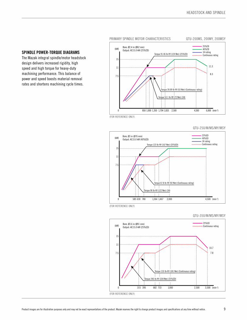
PRIMARY SPINDLE MOTOR CHARACTERISTICS
Bore: Ø2.4 in (Ø62 mm)Output: AC15.0 kW (25%ED)(kW)
15
11
7.5
0 850 1,000 1,350 1,704 1,833 2,500 4,500 6,000 (min-1)
11.3
8.3
25%ED40%ED1H ratingContinuous ratingTorque 91.46 lb-ftf (124 Nm) (25%ED)
Torque 39.09 lb-ftf (53 Nm) (Continuous rating)
Torque 53.1 lb-ftf (72 Nm) (1H)
Bore: Ø3 in (Ø76 mm)Output: AC15.0 kW (40%ED)(kW)
15
11
7.5
0 585 630 780 1,364 1,467 2,000 4,500 (min-1)
25%ED40%ED1H ratingContinuous ratingTorque 123 lb-ftf (167 Nm) (25%ED)
Torque 67.8 lb-ftf (92 Nm) (Continuous rating)
Torque 90 lb-ftf (122 Nm) (1H)
Bore: Ø3.6 in (Ø91 mm)Output: AC15.0 kW (25%ED)(kW)
15
11
7.5
0 315 395 682 733 1,000 3,500 (min-1)
10.7
7.8
25%EDContinuous rating
Torque 133 lb-ftf (181 Nm) (Continuous rating)
Torque 246 lb-ftf (334 Nm) (25%ED)
2,500
SPINDLE POWER-TORQUE DIAGRAMSThe Mazak integral spindle/motor headstock design delivers increased rigidity, high speed and high torque for heavy-duty machining performance. This balance of power and speed boosts material removal rates and shortens machining cycle times.
QTU-200MS, 200MY, 200MSY
QTU-250/M/MS/MY/MSY
QTU-350/M/MS/MY/MSY
(FOR REFERENCE ONLY)
(FOR REFERENCE ONLY)
(FOR REFERENCE ONLY)

10 Product images are for illustration purposes only and may not be exact representations of the product. Mazak reserves the right to change product images and specifications at any time without notice.
SERVO TURRET
QTU Series machines feature innovative turrets that use roller gear cam drive systems for smooth, high-speed, high-accuracy digital indexing as well as expandability.
Benefits of the enhanced 12-position, integral-motor turrets:• High-speed, high-accuracy indexing• Maximum rigidity• Expandability and versatility• Low maintenance
FAST, INTERFERENCE-FREE OPERATION For significantly reduced non-cut times, QTU turrets are bi-directional and thus rotate — via the shortest path possible — to quickly bring up the next programmed tool. Brushless servomotors provide hydraulic clamping strength, while non-lift indexing capability prevents contamination.
ROLLER GEAR CAM DRIVE SYSTEM QTU turrets feature industry-proven drive systems that enhance overall machine productivity and performance. The system delivers smooth acceleration/deceleration and extreme durability along with cost-effective and easy maintainability.
SERVO TURRET
3-AXIS SERVO TURRET
ROLLER GEAR CAM DRIVE SYSTEM The Mazak Roller Gear Cam Drive System provides ample accessibility for fast and easy routine maintenance.

11Product images are for illustration purposes only and may not be exact representations of the product. Mazak reserves the right to change product images and specifications at any time without notice.
TAILSTOCK
NC SERVO-DRIVEN TAILSTOCK Mazak’s fully programmable NC servo-driven tailstock provides simple, precise and automatic operation to reduce setup time and increase productivity. The QTU tailstock includes drilling capability as standard.
Through the part program, the tailstock moves to a known position and the center makes contact with the part at a programmed thrust. With its positive independent drive system, the tailstock has on centerline drilling capability to add part processing versatility.
Servo motor-controlled movement and thrust give Mazak’s NC tailstock increased operability and ease of use. The servo motor monitors tailstock thrust and adjusts on-the-fly while a workpiece is being held.
Thrust settings are adjustable in increments of 22.5 ft-lb (0.1 kN) of force. The tailstock gives users the option to set thrust levels according to workpiece material and shape. This eliminates the risk of part damage while simultaneously providing safe and secure holding and support.
Tailstock specifications include:• Center bore Morse taper MT No.5 live center• Travels (depending on machine model) from
13.250" (340 mm) to 22.125" (565 mm)
LOW-THRUST OPERATION For extremely delicate and soft workpiece materials such as phenolic and resins, a low-thrust function provides holding force settings below 225 ft-lb (1 kN).
TAILSTOCK
NC SERVO-DRIVEN TAILSTOCK
12 Product images are for illustration purposes only and may not be exact representations of the product. Mazak reserves the right to change product images and specifications at any time without notice.
MILLING OPTION
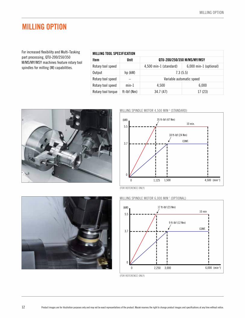
For increased flexibility and Multi-Tasking part processing, QTU-200/250/350 M/MS/MY/MSY machines feature rotary tool spindles for milling (M) capabilities.
MILLING OPTION
MILLING TOOL SPECIFICATION
Item Unit QTU-200/250/350 M/MS/MY/MSY
Rotary tool speed 4,500 min-1 (standard) 6,000 min-1 (optional)
Output hp (kW) 7.3 (5.5)
Rotary tool speed – Variable automatic speed
Rotary tool speed min-1 4,500 6,000
Rotary tool torque ft-lbf (Nm) 34.7 (47) 17 (23)
MILLING SPINDLE MOTOR 4,500 MIN-1 (STANDARD)
MILLING SPINDLE MOTOR 6,000 MIN-1 (OPTIONAL)
0
0 1,125 4,5001,500
3.7
5.5
(kW) 35 ft-lbf (47 Nm)
(min-1)
18 ft-lbf (24 Nm)
10 min.
CONT.
0
0 2,250 3,000 6,000
3.7
5.5
(kW) 17 ft-lbf (23 Nm)
(min-1)
9 ft-lbf (12 Nm)
10 min
CONT.
0
0 1,125 4,5001,500
3.7
5.5
(kW) 35 ft-lbf (47 Nm)
(min-1)
18 ft-lbf (24 Nm)
10 min.
CONT.
0
0 2,250 3,000 6,000
3.7
5.5
(kW) 17 ft-lbf (23 Nm)
(min-1)
9 ft-lbf (12 Nm)
10 min
CONT.
(FOR REFERENCE ONLY)
(FOR REFERENCE ONLY)
13Product images are for illustration purposes only and may not be exact representations of the product. Mazak reserves the right to change product images and specifications at any time without notice.
Y-AXIS OPTION
Y-AXIS OPTION
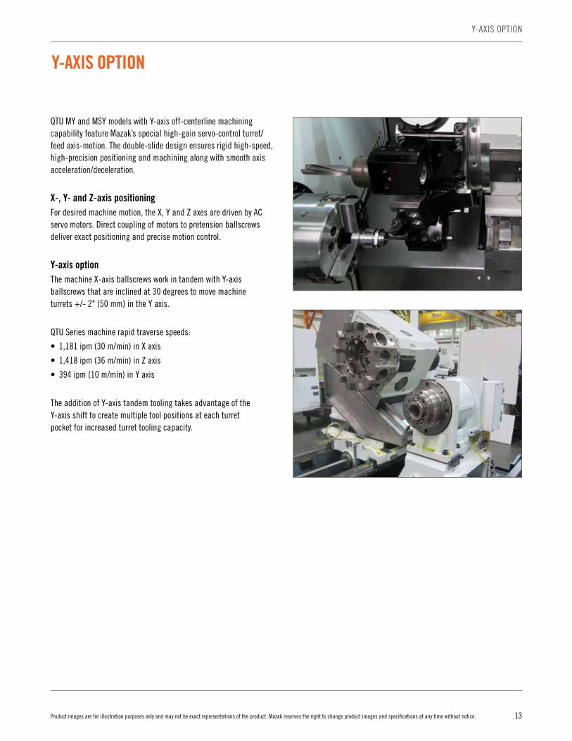
QTU MY and MSY models with Y-axis off-centerline machining capability feature Mazak’s special high-gain servo-control turret/feed axis-motion. The double-slide design ensures rigid high-speed, high-precision positioning and machining along with smooth axis acceleration/deceleration.
X-, Y- and Z-axis positioningFor desired machine motion, the X, Y and Z axes are driven by AC servo motors. Direct coupling of motors to pretension ballscrews deliver exact positioning and precise motion control.
Y-axis optionThe machine X-axis ballscrews work in tandem with Y-axis ballscrews that are inclined at 30 degrees to move machine turrets +/- 2" (50 mm) in the Y axis.
QTU Series machine rapid traverse speeds:
• 1,181 ipm (30 m/min) in X axis
• 1,418 ipm (36 m/min) in Z axis
• 394 ipm (10 m/min) in Y axis
The addition of Y-axis tandem tooling takes advantage of the Y-axis shift to create multiple tool positions at each turret pocket for increased turret tooling capacity.
14 Product images are for illustration purposes only and may not be exact representations of the product. Mazak reserves the right to change product images and specifications at any time without notice.
SECOND SPINDLE OPTION
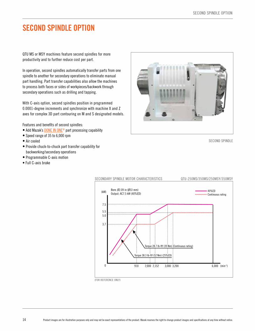
QTU MS or MSY machines feature second spindles for more productivity and to further reduce cost per part.
In operation, second spindles automatically transfer parts from one spindle to another for secondary operations to eliminate manual part handling. Part transfer capabilities also allow the machines to process both faces or sides of workpieces/backwork through secondary operations such as drilling and tapping.
With C-axis option, second spindles position in programmed 0.0001-degree increments and synchronize with machine X and Z axes for complex 3D part contouring on M and S designated models.
Features and benefits of second spindles:• Add Mazak’s DONE IN ONE® part processing capability• Speed range of 35 to 6,000 rpm• Air cooled • Provide chuck-to-chuck part transfer capability for
backworking/secondary operations• Programmable C-axis motion• Full C-axis brake
SECOND SPINDLE OPTION
SECONDARY SPINDLE MOTOR CHARACTERISTICS QTU-250MS/350MS/250MSY/350MSY
Bore: Ø2.09 in (Ø53 mm)Output: AC7.5 kW (40%ED)(kW)
7.5
5.55.0
3.7
910 2,000 2,152 3,000 3,200 6,000 (min-1)0
Torque 38.3 Ib-ftf (52 Nm) (25%ED)
40%EDContinuous rating
Torque 28.7 Ib-ftf (39 Nm) (Continuous rating)
SECOND SPINDLE
(FOR REFERENCE ONLY)
15Product images are for illustration purposes only and may not be exact representations of the product. Mazak reserves the right to change product images and specifications at any time without notice.
OPTIONAL EQUIPMENT
OPTIONAL EQUIPMENT
Mazak offers a wide array of options from which to choose for the QTU Series that further enhance machine performance, increase uptime and boost overall operational efficiency.
• Bar feeder and automatic parts catchers for easily implemented, unattended operations
• Automated loading systems (pre-engineered or custom systems) are available for lights out production
• Tool eye automatically measures tool tip positions and detects wear/damage and greatly reduces setup time
• Automatic front door open/close for M-code controlled opening and closing
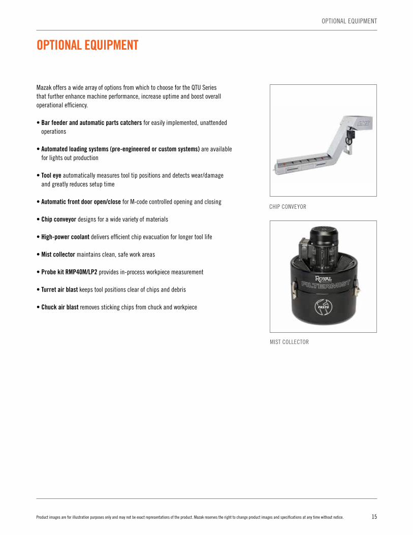
• Chip conveyor designs for a wide variety of materials
• High-power coolant delivers efficient chip evacuation for longer tool life
• Mist collector maintains clean, safe work areas
• Probe kit RMP40M/LP2 provides in-process workpiece measurement
• Turret air blast keeps tool positions clear of chips and debris
• Chuck air blast removes sticking chips from chuck and workpiece
CHIP CONVEYOR
MIST COLLECTOR
16 Product images are for illustration purposes only and may not be exact representations of the product. Mazak reserves the right to change product images and specifications at any time without notice.
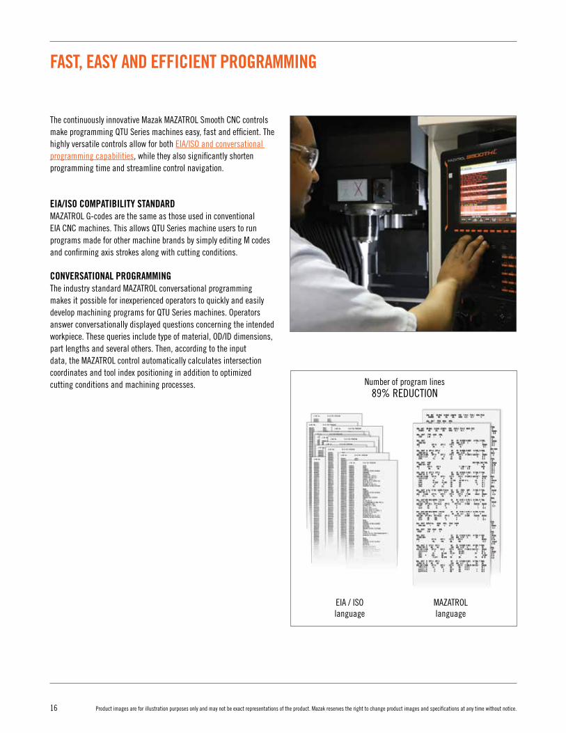
FAST, EASY AND EFFICIENT PROGRAMMING
The continuously innovative Mazak MAZATROL Smooth CNC controls make programming QTU Series machines easy, fast and efficient. The highly versatile controls allow for both EIA/ISO and conversational programming capabilities, while they also significantly shorten programming time and streamline control navigation.
EIA/ISO COMPATIBILITY STANDARDMAZATROL G-codes are the same as those used in conventional EIA CNC machines. This allows QTU Series machine users to run programs made for other machine brands by simply editing M codes and confirming axis strokes along with cutting conditions.
CONVERSATIONAL PROGRAMMINGThe industry standard MAZATROL conversational programming makes it possible for inexperienced operators to quickly and easily develop machining programs for QTU Series machines. Operators answer conversationally displayed questions concerning the intended workpiece. These queries include type of material, OD/ID dimensions, part lengths and several others. Then, according to the input data, the MAZATROL control automatically calculates intersection coordinates and tool index positioning in addition to optimized cutting conditions and machining processes.
MAZATROLlanguage
EIA / ISOlanguage
Number of program lines89% REDUCTION

17Product images are for illustration purposes only and may not be exact representations of the product. Mazak reserves the right to change product images and specifications at any time without notice.
PROCESS HOME SCREENSInnovative touch operation of the MAZATROL SmoothC CNC streamlines data entry and minimizes the number of displays to reduce programming times for QTU Series machines. Five different home process screens each display their appropriate data in an easy to understand manner. Operators can touch icons to quickly navigate to additional screen displays.
Process home screens include:• Programming• Tool data• Setup• Machining• Maintenance
FAST, EASY AND EFFICIENT PROGRAMMING
18 Product images are for illustration purposes only and may not be exact representations of the product. Mazak reserves the right to change product images and specifications at any time without notice.
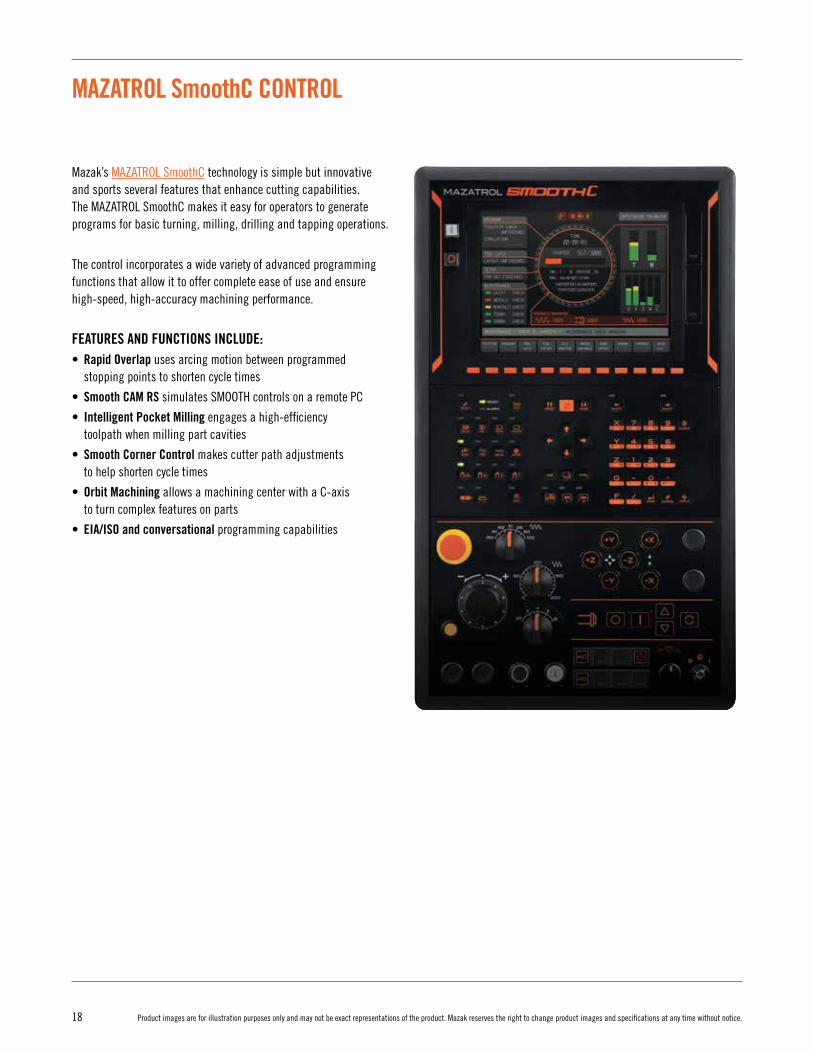
MAZATROL SmoothC CONTROL
Mazak’s MAZATROL SmoothC technology is simple but innovative and sports several features that enhance cutting capabilities. The MAZATROL SmoothC makes it easy for operators to generate programs for basic turning, milling, drilling and tapping operations.
The control incorporates a wide variety of advanced programming functions that allow it to offer complete ease of use and ensure high-speed, high-accuracy machining performance.
FEATURES AND FUNCTIONS INCLUDE:• Rapid Overlap uses arcing motion between programmed
stopping points to shorten cycle times
• Smooth CAM RS simulates SMOOTH controls on a remote PC
• Intelligent Pocket Milling engages a high-efficiency toolpath when milling part cavities
• Smooth Corner Control makes cutter path adjustments to help shorten cycle times
• Orbit Machining allows a machining center with a C-axis to turn complex features on parts
• EIA/ISO and conversational programming capabilities

19Product images are for illustration purposes only and may not be exact representations of the product. Mazak reserves the right to change product images and specifications at any time without notice.
MAZATROL SMOOTHC CONTROL
MAZATROL EIA
Number of controlled axes Simultaneous 2 ~ 4 axes
Least input increment 0.00001 inch, 0.0001 mm, 0.0001º
High speed, high-precision control
Shape error designation, Smooth corner control, Rapid traverse overlap, Rotary axis shape compensation
Shape error designation, Smooth corner control, Rapid traverse overlap, Rotary axis shape compensation,
High-speed machining mode,High-speed smoothing control function
InterpolationPositioning (Linear interpolation), Positioning (Independent interpolation), Linear interpolation, Circular interpolation,
Synchronized milling spindle tapping*
Positioning (Linear interpolation), Positioning (Independent interpolation), Linear interpolation, Circular interpolation,
Spiral interpolation, Helical interpolation, Cylindrical coordinate interpolation*, Fine spline interpolation*,
NURBS interpolation*, Polar coordinate interpolation*, Synchronized milling spindle tapping*
Feed rate
Rapid traverse, Cutting feed, Cutting feed (per minute), Dwell (specified time, specified number of rotation), Rapid traverse override, Cutting feed override, G0 speed variable control, Feedrate clamp, Variable acceleration/deceleration
control, Constant control for G0 tilting*
Rapid traverse, Cutting feed, Cutting feed (per minute), Inverse time feed, Dwell (specified time, specified number of
rotation), Rapid traverse override, Cutting feed override,G0 speed variable control, Feedrate clamp, Time constant
changing for G1, Variable acceleration/deceleration control,Constant control for G0 tilting*
Program registration Max. number of programs: 960, Program storage: 2 MB, Program storage expansion: 8 MB*, Program storage expansion: 32 MB*
Control display Display: 10.4" touch panel, Resolution: VGA
Spindle functions S code output, Spindle speed clamp, Spindle speed override, Spindle speed reaching detection, Multiple position orient, Constant surface speed, Spindle speed command with decimal digits, Synchronized spindle control, Max. speed control for spindle
Tool functionsTool offset pairs: 4000, T code output for tool number,
Tool life monitoring (time),Tool life monitoring (number of machined workpieces)
Tool offset pairs: 4000, T code output for tool number,T code output for group number, Tool life monitoring (time),
Tool life monitoring (number of machined workpieces)
Miscellaneous functions M code output, Simultaneous output of multiple M codes
Tool offset functions Tool position offset, Tool length offset, Tool diameter/tool nose R offset, Tool wear offset
Tool offset pairs 128
Coordinate system Machine coordinate system, Work coordinate system, Local coordinate system, Additional work coordinates (300 set)
Machine functions — Hobbing*, Shaping function*, Dynamic compensation*
Machine compensation G0/G1 independent backlash compensation, Pitch error compensation, Volumetric compensation*
Protection functions Emergency stop, Interlock, Stroke check before travelling, Retraction function for the vertical axis
Automatic operation mode Memory operation Memory operation, Tape operation, MDI operation, EtherNet operation*
Automatic operation control
Optional stop, Dry run, Automatic handle control, MDI control, TPS, Restart, Machine lock
Optional block skip, Optional stop, Dry run, Automatic handle control, MDI control, TPS, Restart, Restart 2, Collation stop,
Machine lock
Manual measuring functions
Tool length and tip teach, Touch sensor coordinates measurement, Workpiece offset measurement, WPC coordinate
measurement, Measurement on machine
Tool length and tip teach, Tool offset teach, Touch sensor coordinates measurement, Workpiece offset measurement, WPC coordinate measurement, Measurement on machine
Automatic measuring functions
WPC coordinate measurement, Auto tool length measurement, Sensor calibration, Tool eye auto tool measurement,
Tool breakage detection, External tool breakage detection*
Auto tool length measurement, Sensor calibration,Tool breakage detection, External tool breakage detection*
MDI measurement Partial auto tool length measurement, Auto tool length measurement, Coordinate measurement
Interface PROFIBUS-DP*, EtherNet I/P*, CC-Link*, USB
Card interface SD card interface
EtherNet 10 M / 100 M / 1 G bps
MAZATROL SmoothC SPECIFICATIONS
* Option
20 Product images are for illustration purposes only and may not be exact representations of the product. Mazak reserves the right to change product images and specifications at any time without notice.
MAZAK AUTOMATION SYSTEMS
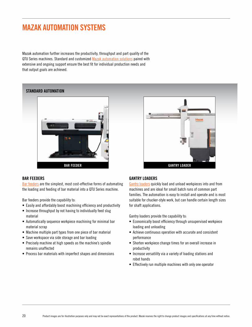
Mazak automation further increases the productivity, throughput and part quality of the QTU Series machines. Standard and customized Mazak automation solutions paired with extensive and ongoing support ensure the best fit for individual production needs and that output goals are achieved.
BAR FEEDER
BAR FEEDERS Bar feeders are the simplest, most cost-effective forms of automating the loading and feeding of bar material into a QTU Series machine.
Bar feeders provide the capability to:• Easily and affordably boost machining efficiency and productivity • Increase throughput by not having to individually feed slug material • Automatically sequence workpiece machining for minimal bar material scrap • Machine multiple part types from one piece of bar material • Save workspace via side storage and bar loading • Precisely machine at high speeds as the machine’s spindle remains unaffected • Process bar materials with imperfect shapes and dimensions
GANTRY LOADERS Gantry loaders quickly load and unload workpieces into and from machines and are ideal for small batch runs of common part families. The automation is easy to install and operate and is most suitable for chucker-style work, but can handle certain length sizes for shaft applications.
Gantry loaders provide the capability to:• Economically boost efficiency through unsupervised workpiece loading and unloading • Achieve continuous operation with accurate and consistent performance • Shorten workpiece change times for an overall increase in productivity • Increase versatility via a variety of loading stations and robot hands• Effectively run multiple machines with only one operator
GANTRY LOADER
STANDARD AUTOMATION

21Product images are for illustration purposes only and may not be exact representations of the product. Mazak reserves the right to change product images and specifications at any time without notice.
ENGINEERED SOLUTIONS
MAZAK AUTOMATION SYSTEMS
CUSTOM ENGINEERED SOLUTIONSA variety of custom automation solutions tailored specifically to individual customer needs are available for QTU Series machines. Mazak’s expert applications engineers design and implement systems and software that will boost productivity and ensure maximum return on customer automation investments.
Custom engineered solutions provide the capability to:• Boost machine throughput and part quality• Ensure production reliability and repeatability• Service one or more machines with minimal operator intervention• Perform multiple tasks and eliminate the number of necessary components in a system• Keep machines running 24/7 without additional night or weekend shifts• Reduce in-process inventory and accomplish just-in-time production
ARTICULATED ROBOTSArticulated robots automate part transfers and peripheral operations. They also eliminate the challenges associated with handling large, heavy or cumbersome parts. Robot configurations range from two jointed to seven jointed to meet the needs of various applications.
CELLS AND SYSTEMS ARTICULATED ROBOT
22 Product images are for illustration purposes only and may not be exact representations of the product. Mazak reserves the right to change product images and specifications at any time without notice.
MAZAK DIGITAL SOLUTIONS
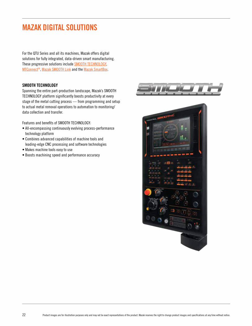
For the QTU Series and all its machines, Mazak offers digital solutions for fully integrated, data-driven smart manufacturing. These progressive solutions include SMOOTH TECHNOLOGY, MTConnect®, Mazak SMOOTH Link and the Mazak SmartBox.
SMOOTH TECHNOLOGYSpanning the entire part-production landscape, Mazak’s SMOOTH TECHNOLOGY platform significantly boosts productivity at every stage of the metal cutting process — from programming and setup to actual metal removal operations to automation to monitoring/data collection and transfer.
Features and benefits of SMOOTH TECHNOLOGY:• All-encompassing continuously evolving process-performance
technology platform• Combines advanced capabilities of machine tools and
leading-edge CNC processing and software technologies• Makes machine tools easy to use• Boosts machining speed and performance accuracy
23Product images are for illustration purposes only and may not be exact representations of the product. Mazak reserves the right to change product images and specifications at any time without notice.
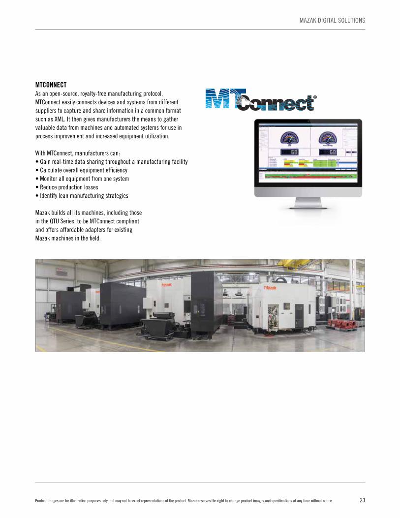
MTCONNECTAs an open-source, royalty-free manufacturing protocol,MTConnect easily connects devices and systems from different suppliers to capture and share information in a common format such as XML. It then gives manufacturers the means to gather valuable data from machines and automated systems for use in process improvement and increased equipment utilization.
With MTConnect, manufacturers can:• Gain real-time data sharing throughout a manufacturing facility• Calculate overall equipment efficiency• Monitor all equipment from one system• Reduce production losses• Identify lean manufacturing strategies
Mazak builds all its machines, including those in the QTU Series, to be MTConnect compliant and offers affordable adapters for existing Mazak machines in the field.
MAZAK DIGITAL SOLUTIONS
®

24 Product images are for illustration purposes only and may not be exact representations of the product. Mazak reserves the right to change product images and specifications at any time without notice.
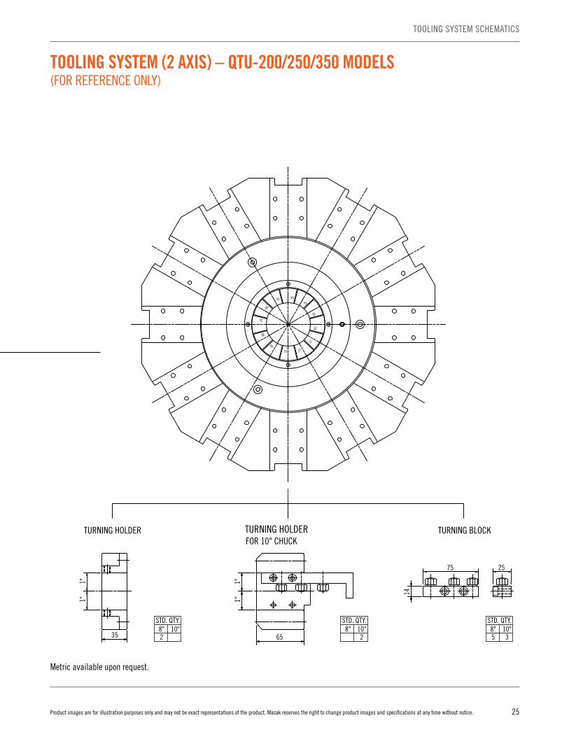
TOOLING SYSTEM (2 AXIS) – QTU-200/250/350 MODELS (FOR REFERENCE ONLY)
Ø1"Ø1-1/4"
Ø1-1
/2"
Ø1-1/2"
Ø1-1
/2"
Ø40
Ø1-1
/2"
d8"11
10"11
STD. QTY.8"2
10"2
STD. QTY.
8"2
10"STD. QTY.
8" 10"2
STD. QTY.8"5
10"3
STD. QTY.8"1
10"1
STD. QTY.
8" 10"STD. QTY.
Ø3/4"Ø5/8"Ø1/2"Ø3/8"
Ø5/16"
d8" 10"
STD. QTY.
M.T.3M.T.2M.T.1
M.T.8"
1
10"
1
STD. QTY.
Ø32Ø25Ø20
d8" 10"
STD. QTY.
M.T.
M.T. DRILL SOCKET
TURNING HOLDERFOR 10" CHUCK
TURNING HOLDER TURNING BLOCKU DRILL SOCKETU DRILL HOLDER
FACING HOLDER
BORING BAR HOLDER
BORING BAR SOCKET
65
1"1"
1"1"
35
Ø40
2"
1"1"
1.5"
2"
ØdØd
Ød
14
75 25
04
03
0201
12
1110
09
0807
06
05
Metric available upon request.
25Product images are for illustration purposes only and may not be exact representations of the product. Mazak reserves the right to change product images and specifications at any time without notice.
TOOLING SYSTEM SCHEMATICS
TOOLING SYSTEM (2 AXIS) – QTU-200/250/350 MODELS (FOR REFERENCE ONLY)
Ø1"Ø1-1/4"
Ø1-1
/2"
Ø1-1/2"
Ø1-1
/2"
Ø40
Ø1-1
/2"
d8"11
10"11
STD. QTY.8"2
10"2
STD. QTY.
8"2
10"STD. QTY.
8" 10"2
STD. QTY.8"5
10"3
STD. QTY.8"1
10"1
STD. QTY.
8" 10"STD. QTY.
Ø3/4"Ø5/8"Ø1/2"Ø3/8"
Ø5/16"
d8" 10"
STD. QTY.
M.T.3M.T.2M.T.1
M.T.8"
1
10"
1
STD. QTY.
Ø32Ø25Ø20
d8" 10"
STD. QTY.
M.T.
M.T. DRILL SOCKET
TURNING HOLDERFOR 10" CHUCK
TURNING HOLDER TURNING BLOCKU DRILL SOCKETU DRILL HOLDER
FACING HOLDER
BORING BAR HOLDER
BORING BAR SOCKET
65
1"1"
1"1"
35
Ø40
2"
1"1"
1.5"
2"
ØdØd
Ød
14
75 25
04
03
0201
12
1110
09
0807
06
05
Metric available upon request.

26 Product images are for illustration purposes only and may not be exact representations of the product. Mazak reserves the right to change product images and specifications at any time without notice.
Metric available upon request.
5B078013001
0
Ø1-1/2"
Ø5/16"
Ø3/8"
Ø1/2"
Ø5/8"
Ø3/4"
Ø1"
Ø1-1/4"
2B078001920
Ø40
M.T.
Ø1-1
/2"
1"X1"X6"
Ø1-1
/2"
d
1"X1"X6"
100
60.81"X1"X6"
100
38.6
1"X1"X6"
80
641"X1"X6"
80
38.6
ER32-13ER32-12ER32-11ER32-10ER32-9ER32-8ER32-7ER32-6ER32-5
ER32-4.5ER32-4
ER32-3.5ER32-3
ER32-2.5ER32-2
TYPE
CHUCK COLLET
ER32-14ER32-15ER32-16ER32-17ER32-18ER32-19ER32-20
STD. QTY
1
1
STD. QTY
CHUCK COLLET (applicable to through coolant)
AR32-OH-13.5
AR32-OH-12.5
AR32-OH-11.5
AR32-OH-10.5
AR32-OH-9.5
AR32-OH-8.5
TYPE
AR32-OH-8
AR32-OH-9
AR32-OH-10
AR32-OH-11
AR32-OH-12
AR32-OH-13
AR32-OH-14
AR32-OH-19.5
AR32-OH-18.5
AR32-OH-17.5
AR32-OH-16.5
AR32-OH-15.5
AR32-OH-14.5AR32-OH-15
AR32-OH-16
AR32-OH-17
AR32-OH-18
AR32-OH-19
AR32-OH-20
224
10" CHUCK8" CHUCK
STD. QTY
M/MY MS/MSY
12
1
11
11
2
4
2
MS/MSYM/MY
MS/MSYM/MY
MS/MSYM/MY MS/MSYM/MY
MS/MSYM/MY
MS/MSYM/MY
MS/MSYM/MY
CAP PLATE
CAP PLATESTD. QTY
Ø32
Ø25
Ø20 Ø40
dd
U DRILL HOLDERU DRILL SOCKETdd
d
STD. QTYSTD. QTY
MS/MSYM/MY
NO.3
NO.2 1 1
NO.1
M.T.STD. QTY
U DRILL
OFFSET TURNING HOLDER
d
BORING BAR HOLDER
BORING BAR
BORING BAR SOCKET
UNIT NO.DRILL MILL
DRILL
FACING HOLDER
DRILL SOCKETd
d
TURRET
STD. QTY
STD. QTY
CHUCK COLLET
CHUCK COLLET
MILL
DRILL
PARTS CODE NO.
HOOK SPANNER
CHUCK COLLETMILLDRILL
REMOVAL TOOL(FOR V-TYPE MILLING HOLDER)
REMOVAL TOOL(FOR V-TYPE LONG NOSE MILLING HOLDER)
STD. QTY
FACE MILL
Ø50
MS/MSYM/MYMAX. MILLING SPEED
STD. QTY
6000 rpm
6000 rpm(for through coolant)
MS/MSY1
M/MY1
MAX. MILLING SPEED
STD. QTY
6000 rpm
6000 rpm(for through coolant)
MS/MSY1
M/MY1
MAX. MILLING SPEED
STD. QTY
6000 rpm
6000 rpm(for through coolant)
Ø50
REMOVAL TOOL H-TYPE MILLING HOLDER(WITH Ø20 CHUCK COLLET)
V-TYPE MILLING HOLDER(WITH Ø20 CHUCK COLLET)
V-TYPE LONG NOSE MILLING HOLDER(WITH Ø20 CHUCK COLLET)
FACE MILL HOLDER
(FOR H-TYPE MILLING HOLDER)
TURNING HOLDER
TURNING HOLDER FOR 10"CHUCK OFFSET TURNING HOLDER FOR 10"CHUCK
M/MY1
MS/MSY1
STD. QTY.
M/MY1
MS/MSY1
STD. QTY.
M/MY1
MS/MSY1
STD. QTY.
M/MY1
MS/MSY1
d
d
d
STD. QTY.
M/MY MS/MSYSTD. QTY.
M/MY MS/MSYSTD. QTY.
M/MY1
MS/MSYSTD. QTY.
M/MY2
MS/MSY2
STD. QTY.
TOOLING SYSTEM – M/MS/MY/MSY 1ST PROCESS (FOR REFERENCE ONLY)

27Product images are for illustration purposes only and may not be exact representations of the product. Mazak reserves the right to change product images and specifications at any time without notice.
TOOLING SYSTEM SCHEMATICS
Metric available upon request.
5B078013001
0
Ø1-1/2"
Ø5/16"
Ø3/8"
Ø1/2"
Ø5/8"
Ø3/4"
Ø1"
Ø1-1/4"
2B078001920
Ø40
M.T.
Ø1-1
/2"
1"X1"X6"
Ø1-1
/2"
d
1"X1"X6"
100
60.81"X1"X6"
100
38.6
1"X1"X6"
80
641"X1"X6"
80
38.6
ER32-13ER32-12ER32-11ER32-10ER32-9ER32-8ER32-7ER32-6ER32-5
ER32-4.5ER32-4
ER32-3.5ER32-3
ER32-2.5ER32-2
TYPE
CHUCK COLLET
ER32-14ER32-15ER32-16ER32-17ER32-18ER32-19ER32-20
STD. QTY
1
1
STD. QTY
CHUCK COLLET (applicable to through coolant)
AR32-OH-13.5
AR32-OH-12.5
AR32-OH-11.5
AR32-OH-10.5
AR32-OH-9.5
AR32-OH-8.5
TYPE
AR32-OH-8
AR32-OH-9
AR32-OH-10
AR32-OH-11
AR32-OH-12
AR32-OH-13
AR32-OH-14
AR32-OH-19.5
AR32-OH-18.5
AR32-OH-17.5
AR32-OH-16.5
AR32-OH-15.5
AR32-OH-14.5AR32-OH-15
AR32-OH-16
AR32-OH-17
AR32-OH-18
AR32-OH-19
AR32-OH-20
224
10" CHUCK8" CHUCK
STD. QTY
M/MY MS/MSY
12
1
11
11
2
4
2
MS/MSYM/MY
MS/MSYM/MY
MS/MSYM/MY MS/MSYM/MY
MS/MSYM/MY
MS/MSYM/MY
MS/MSYM/MY
CAP PLATE
CAP PLATESTD. QTY
Ø32
Ø25
Ø20 Ø40
dd
U DRILL HOLDERU DRILL SOCKETdd
d
STD. QTYSTD. QTY
MS/MSYM/MY
NO.3
NO.2 1 1
NO.1
M.T.STD. QTY
U DRILL
OFFSET TURNING HOLDER
d
BORING BAR HOLDER
BORING BAR
BORING BAR SOCKET
UNIT NO.DRILL MILL
DRILL
FACING HOLDER
DRILL SOCKETd
d
TURRET
STD. QTY
STD. QTY
CHUCK COLLET
CHUCK COLLET
MILL
DRILL
PARTS CODE NO.
HOOK SPANNER
CHUCK COLLETMILLDRILL
REMOVAL TOOL(FOR V-TYPE MILLING HOLDER)
REMOVAL TOOL(FOR V-TYPE LONG NOSE MILLING HOLDER)
STD. QTY
FACE MILL
Ø50
MS/MSYM/MYMAX. MILLING SPEED
STD. QTY
6000 rpm
6000 rpm(for through coolant)
MS/MSY1
M/MY1
MAX. MILLING SPEED
STD. QTY
6000 rpm
6000 rpm(for through coolant)
MS/MSY1
M/MY1
MAX. MILLING SPEED
STD. QTY
6000 rpm
6000 rpm(for through coolant)
Ø50
REMOVAL TOOL H-TYPE MILLING HOLDER(WITH Ø20 CHUCK COLLET)
V-TYPE MILLING HOLDER(WITH Ø20 CHUCK COLLET)
V-TYPE LONG NOSE MILLING HOLDER(WITH Ø20 CHUCK COLLET)
FACE MILL HOLDER
(FOR H-TYPE MILLING HOLDER)
TURNING HOLDER
TURNING HOLDER FOR 10"CHUCK OFFSET TURNING HOLDER FOR 10"CHUCK
M/MY1
MS/MSY1
STD. QTY.
M/MY1
MS/MSY1
STD. QTY.
M/MY1
MS/MSY1
STD. QTY.
M/MY1
MS/MSY1
d
d
d
STD. QTY.
M/MY MS/MSYSTD. QTY.
M/MY MS/MSYSTD. QTY.
M/MY1
MS/MSYSTD. QTY.
M/MY2
MS/MSY2
STD. QTY.
TOOLING SYSTEM – M/MS/MY/MSY 1ST PROCESS (FOR REFERENCE ONLY)
28 Product images are for illustration purposes only and may not be exact representations of the product. Mazak reserves the right to change product images and specifications at any time without notice.
Metric available upon request.
0.079" (Ø2)
0.118" (Ø3)
0.157" (Ø4)
0.197" (Ø5)
0.236" (Ø6)
0.276" (Ø7)
0.315" (Ø8)
0.354" (Ø9)
0.394"(Ø10)
0.433"(Ø11)
0.472"(Ø12)
0.512"(Ø13)
0.551"(Ø14)
0.591"(Ø15)
0.630"(Ø16)
0.138"(Ø3.5)
0.177"(Ø4.5)
0.098"(Ø2.5)
0.789"(Ø20)
0.748"(Ø19)
0.709"(Ø18)
0.669"(Ø17)
COLLET
Ø1" 1
d STD. QTY
STD. QTY
d
d
M.T.
NO.1
NO.2
STD. QTY
Ø1"
M.T.
DRILL SOCKET
DRILL
Ø3/4"
Ø5/8"
Ø1/2"
Ø3/8"
Ø5/16"
STD. QTY
Ø1"
d
d
1
TURRET
MILL
DRILL
BORING BAR
1"X1"X4.5" 1"X1"X4.5"
STD. QTYH-TYPE BACK MILLING HOLDER(WITH Ø20 CHUCK COLLET
STD. QTYTURNING HOLDER (SS)
1
STD. QTY
BORING BAR HOLDER (SS)
BORING BAR SOCKET
CUT-OFF HOLDER
STD. QTY
REMOVAL TOOL(FOR H-TYPE BACK MILLING HOLDER)
HOOK SPANNER
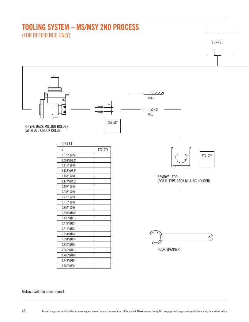
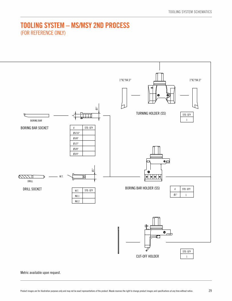
TOOLING SYSTEM – MS/MSY 2ND PROCESS (FOR REFERENCE ONLY)
29Product images are for illustration purposes only and may not be exact representations of the product. Mazak reserves the right to change product images and specifications at any time without notice.
TOOLING SYSTEM SCHEMATICS
Metric available upon request.
0.079" (Ø2)
0.118" (Ø3)
0.157" (Ø4)
0.197" (Ø5)
0.236" (Ø6)
0.276" (Ø7)
0.315" (Ø8)
0.354" (Ø9)
0.394"(Ø10)
0.433"(Ø11)
0.472"(Ø12)
0.512"(Ø13)
0.551"(Ø14)
0.591"(Ø15)
0.630"(Ø16)
0.138"(Ø3.5)
0.177"(Ø4.5)
0.098"(Ø2.5)
0.789"(Ø20)
0.748"(Ø19)
0.709"(Ø18)
0.669"(Ø17)
COLLET
Ø1" 1
d STD. QTY
STD. QTY
d
d
M.T.
NO.1
NO.2
STD. QTY
Ø1"
M.T.
DRILL SOCKET
DRILL
Ø3/4"
Ø5/8"
Ø1/2"
Ø3/8"
Ø5/16"
STD. QTY
Ø1"
d
d
1
TURRET
MILL
DRILL
BORING BAR
1"X1"X4.5" 1"X1"X4.5"
STD. QTYH-TYPE BACK MILLING HOLDER(WITH Ø20 CHUCK COLLET
STD. QTYTURNING HOLDER (SS)
1
STD. QTY
BORING BAR HOLDER (SS)
BORING BAR SOCKET
CUT-OFF HOLDER
STD. QTY
REMOVAL TOOL(FOR H-TYPE BACK MILLING HOLDER)
HOOK SPANNER
TOOLING SYSTEM – MS/MSY 2ND PROCESS (FOR REFERENCE ONLY)
30 Product images are for illustration purposes only and may not be exact representations of the product. Mazak reserves the right to change product images and specifications at any time without notice.
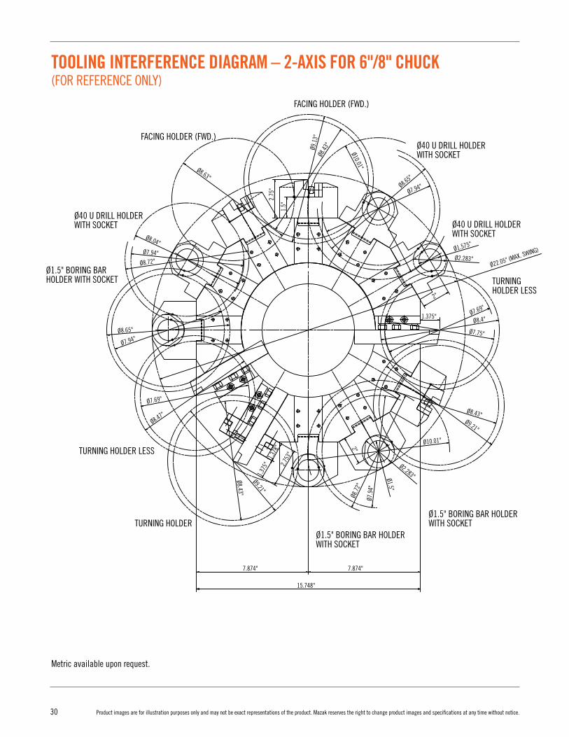
TOOLING INTERFERENCE DIAGRAM – 2-AXIS FOR 6"/8" CHUCK (FOR REFERENCE ONLY)
2"
1.375"
2"
1.378
"2.
75"
1.5"
Ø9.21"
Ø8.43"
Ø8.43
"
Ø9.1
3"
Ø8.63"
Ø9.64
"
Ø10.63"
Ø8.63"
Ø10.63"
Ø9.21"
Ø8.43"
Ø8.04"
Ø10.01"
Ø10.01"Ø8.63"
Ø7.75"
Ø8.04"
Ø2.283"
Ø1.575"
2.753
"
Ø8.43"
Ø9.14"
7.874"7.874"
15.748"
Ø7.9
4"
Ø2.283"Ø1.5"
Ø8.7
2"
Ø8.4"Ø7.69"
Ø7.94"Ø8.65"
Ø8.72"
Ø7.94"
Ø8.65"
Ø7.94"
Ø8.47"
Ø7.69"
Ø9.21"
Ø8.43"
1.375
"
FACING HOLDER (FWD.)
Ø40 U DRILL HOLDERWITH SOCKET Ø40 U DRILL HOLDER
WITH SOCKET
Ø40 U DRILL HOLDERWITH SOCKET
Ø40 U DRILL HOLDERWITH SOCKET
Ø1.5" BORING BAR HOLDER WITH SOCKET
Ø1.5" BORING BAR HOLDER WITH SOCKET
Ø1.5" BORING BAR HOLDER WITH SOCKET
Ø1.5" BORING BAR HOLDER WITH SOCKET
FACING HOLDER (FWD.)
FACING HOLDER (FWD.)
TURNING HOLDERTURNING HOLDER LESSFACING HOLDER (REV.)
FACING HOLDER (REV.)
FACING HOLDER (REV.)
TURNING HOLDER
TURNING HOLDER
TURNING HOLDER LESS
TURNING HOLDER LESS
Ø22.05" (MAX. SWING)
Metric available upon request.
31Product images are for illustration purposes only and may not be exact representations of the product. Mazak reserves the right to change product images and specifications at any time without notice.
TOOLING INTERFERENCE DIAGRAM
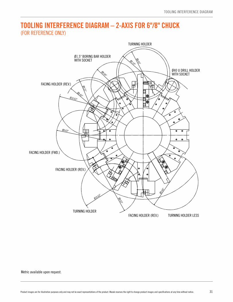
TOOLING INTERFERENCE DIAGRAM – 2-AXIS FOR 6"/8" CHUCK (FOR REFERENCE ONLY)
2"
1.375"
2"
1.378
"2.
75"
1.5"
Ø9.21"
Ø8.43"
Ø8.43
"
Ø9.1
3"
Ø8.63"
Ø9.64
"
Ø10.63"
Ø8.63"
Ø10.63"
Ø9.21"
Ø8.43"
Ø8.04"
Ø10.01"
Ø10.01"Ø8.63"
Ø7.75"
Ø8.04"
Ø2.283"
Ø1.575"
2.753
"
Ø8.43"
Ø9.14"
7.874"7.874"
15.748"
Ø7.9
4"
Ø2.283"Ø1.5"
Ø8.7
2"
Ø8.4"Ø7.69"
Ø7.94"Ø8.65"
Ø8.72"
Ø7.94"
Ø8.65"
Ø7.94"
Ø8.47"
Ø7.69"
Ø9.21"
Ø8.43"
1.375
"
FACING HOLDER (FWD.)
Ø40 U DRILL HOLDERWITH SOCKET Ø40 U DRILL HOLDER
WITH SOCKET
Ø40 U DRILL HOLDERWITH SOCKET
Ø40 U DRILL HOLDERWITH SOCKET
Ø1.5" BORING BAR HOLDER WITH SOCKET
Ø1.5" BORING BAR HOLDER WITH SOCKET
Ø1.5" BORING BAR HOLDER WITH SOCKET
Ø1.5" BORING BAR HOLDER WITH SOCKET
FACING HOLDER (FWD.)
FACING HOLDER (FWD.)
TURNING HOLDERTURNING HOLDER LESSFACING HOLDER (REV.)
FACING HOLDER (REV.)
FACING HOLDER (REV.)
TURNING HOLDER
TURNING HOLDER
TURNING HOLDER LESS
TURNING HOLDER LESS
Ø22.05" (MAX. SWING)
Metric available upon request.
32 Product images are for illustration purposes only and may not be exact representations of the product. Mazak reserves the right to change product images and specifications at any time without notice.
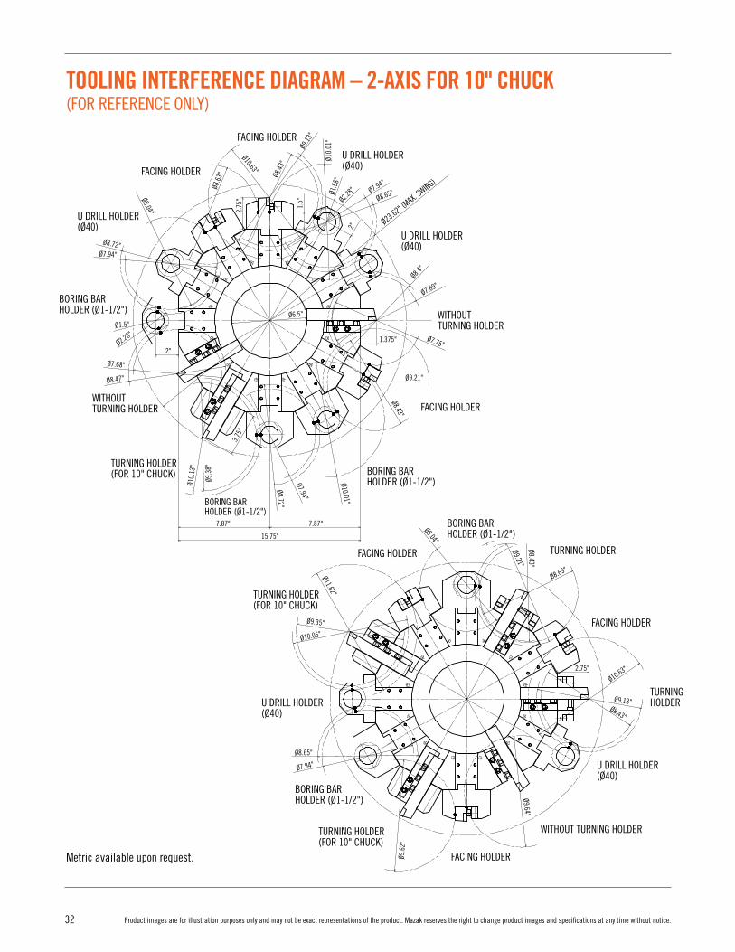
TOOLING INTERFERENCE DIAGRAM – 2-AXIS FOR 10" CHUCK (FOR REFERENCE ONLY)
TURNING HOLDER
TURNING HOLDER
WITHOUT TURNING HOLDER
FACING HOLDER
FACING HOLDER
FACING HOLDER
FACING HOLDER
FACING HOLDER
FACING HOLDER
Ø8.4
3"
Ø9.13
"
Ø10.
01"
Ø1.5
8"Ø2.2
8" Ø7.94"
Ø8.65"
Ø23.62" (MAX. SWING)
Ø8.4"
Ø7.69"
Ø7.75"
Ø6.5"
Ø1.5"
Ø2.28"
Ø7.68"
Ø7.94"
Ø8.72"
Ø8.04"
Ø8.6
3"
Ø10.63"
Ø8.47"
2.75
"
1.5"
1.375"
3.75
"
Ø9.21"
Ø8.43"
Ø8.04"
Ø9.21"Ø8.43"
Ø11.62"Ø10.01"
Ø10.
13"
Ø9.3
8"
Ø7.94"
Ø8.72"
15.75"
7.87"
2"2"
7.87"
Ø8.65"
Ø10.63"
Ø8.63"
2.75"
Ø9.13"Ø8.43"
Ø9.35"
Ø10.06"
Ø7.94"
Ø9.6
2"
Ø9.64"
BORING BAR HOLDER (Ø1-1/2")
BORING BAR HOLDER (Ø1-1/2")
BORING BAR HOLDER (Ø1-1/2")
BORING BAR HOLDER (Ø1-1/2")
BORING BAR HOLDER (Ø1-1/2")
U DRILL HOLDER(Ø40)
TURNING HOLDER(FOR 10" CHUCK)
TURNING HOLDER(FOR 10" CHUCK)
TURNING HOLDER(FOR 10" CHUCK)
U DRILL HOLDER(Ø40)
WITHOUTTURNING HOLDER
WITHOUTTURNING HOLDER
U DRILL HOLDER(Ø40)
U DRILL HOLDER(Ø40)
U DRILL HOLDER(Ø40)
TURNING HOLDER(FOR 10" CHUCK)
WITHOUTTURNING HOLDER
BORING BAR HOLDER (Ø1-1/2")
U DRILL HOLDER
TURNING HOLDER
FACING HOLDER
3.75
"
3.15
"3.
15"
2.75
"
2.75
"
2.5"
0.25
"
2.56
"1.
19"
4.63
"
6"
1.38
"
1.38
"
Ø1.5
"Ø1
.58"
Ø2.2
8"Ø2
.28"
1.15
"2"
1.15
"2"
1.37
"
1.5"
1"
0.25" 3.15"
1" 2.15"
0.25" 3.15"
1" 2.15"
0.25" 0.25"
0.25"
0.25"1.6"
1.85"
1.18"
0.79"
3.15"3.15"6.25" (MAX)
3.15"
3.15"
5" 6.25" (MAX)
0.25"
0.25" 1"
3.15"
Metric available upon request.
33Product images are for illustration purposes only and may not be exact representations of the product. Mazak reserves the right to change product images and specifications at any time without notice.
TOOLING INTERFERENCE DIAGRAM
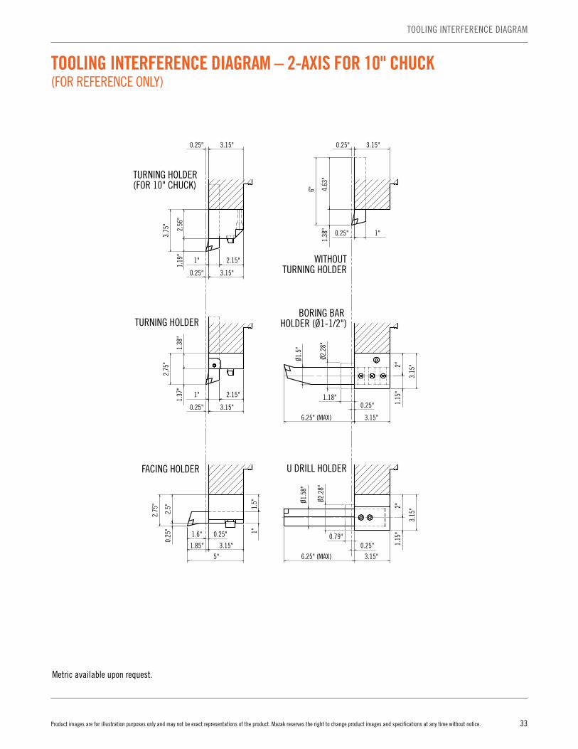
TOOLING INTERFERENCE DIAGRAM – 2-AXIS FOR 10" CHUCK (FOR REFERENCE ONLY)
TURNING HOLDER
TURNING HOLDER
WITHOUT TURNING HOLDER
FACING HOLDER
FACING HOLDER
FACING HOLDER
FACING HOLDER
FACING HOLDER
FACING HOLDER
Ø8.4
3"
Ø9.13
"
Ø10.
01"
Ø1.5
8"Ø2.2
8" Ø7.94"
Ø8.65"
Ø23.62" (MAX. SWING)
Ø8.4"
Ø7.69"
Ø7.75"
Ø6.5"
Ø1.5"
Ø2.28"
Ø7.68"
Ø7.94"
Ø8.72"
Ø8.04"
Ø8.6
3"
Ø10.63"
Ø8.47"
2.75
"
1.5"
1.375"
3.75
"
Ø9.21"
Ø8.43"
Ø8.04"
Ø9.21"Ø8.43"
Ø11.62"Ø10.01"
Ø10.
13"
Ø9.3
8"
Ø7.94"
Ø8.72"
15.75"
7.87"
2"
2"
7.87"
Ø8.65"
Ø10.63"
Ø8.63"
2.75"
Ø9.13"Ø8.43"
Ø9.35"
Ø10.06"
Ø7.94"
Ø9.6
2"
Ø9.64"
BORING BAR HOLDER (Ø1-1/2")
BORING BAR HOLDER (Ø1-1/2")
BORING BAR HOLDER (Ø1-1/2")
BORING BAR HOLDER (Ø1-1/2")
BORING BAR HOLDER (Ø1-1/2")
U DRILL HOLDER(Ø40)
TURNING HOLDER(FOR 10" CHUCK)
TURNING HOLDER(FOR 10" CHUCK)
TURNING HOLDER(FOR 10" CHUCK)
U DRILL HOLDER(Ø40)
WITHOUTTURNING HOLDER
WITHOUTTURNING HOLDER
U DRILL HOLDER(Ø40)
U DRILL HOLDER(Ø40)
U DRILL HOLDER(Ø40)
TURNING HOLDER(FOR 10" CHUCK)
WITHOUTTURNING HOLDER
BORING BAR HOLDER (Ø1-1/2")
U DRILL HOLDER
TURNING HOLDER
FACING HOLDER
3.75
"
3.15
"3.
15"
2.75
"
2.75
"
2.5"
0.25
"
2.56
"1.
19"
4.63
"
6"
1.38
"
1.38
"
Ø1.5
"Ø1
.58"
Ø2.2
8"Ø2
.28"
1.15
"2"
1.15
"2"
1.37
"
1.5"
1"
0.25" 3.15"
1" 2.15"
0.25" 3.15"
1" 2.15"
0.25" 0.25"
0.25"
0.25"1.6"
1.85"
1.18"
0.79"
3.15"3.15"6.25" (MAX)
3.15"
3.15"
5" 6.25" (MAX)
0.25"
0.25" 1"
3.15"
Metric available upon request.
34 Product images are for illustration purposes only and may not be exact representations of the product. Mazak reserves the right to change product images and specifications at any time without notice.
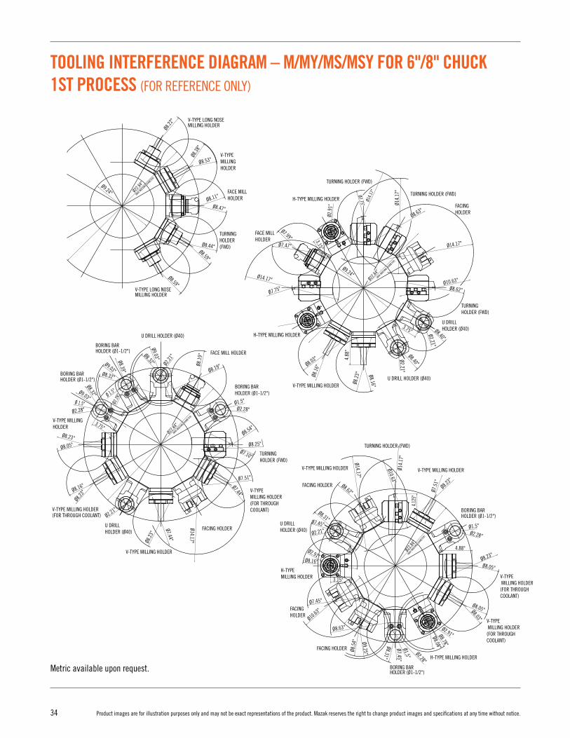
TOOLING INTERFERENCE DIAGRAM – M/MY/MS/MSY FOR 6"/8" CHUCK 1ST PROCESS (FOR REFERENCE ONLY)
TOOL TIP LOCATION OF EACH TOOL
V-TYPE LONG NOSEMILLING HOLDER
V-TYPE MILLING HOLDER(FOR THROUGH COOLANT)
V-TYPE MILLING HOLDER
H-TYPE MILLING HOLDER
U DRILL HOLDER (Ø40)
BORING BAR HOLDER (Ø1-1/2")
FACING HOLDER
TURNING HOLDER (FWD)
FACE MILL HOLDER
BORING BARHOLDER (Ø1-1/2")
BORING BARHOLDER (Ø1-1/2")
BORING BARHOLDER (Ø1-1/2")
BORING BARHOLDER (Ø1-1/2")
BORING BARHOLDER (Ø1-1/2")
FACING HOLDER
U DRILL HOLDER (Ø40)
V-TYPE MILLING HOLDER(FOR THROUGH COOLANT)
V-TYPE MILLING HOLDER
U DRILL HOLDER (Ø40)
V-TYPE MILLING HOLDER(FOR THROUGH COOLANT)
V-TYPE MILLING HOLDER
TURNING HOLDER (FWD)
FACING HOLDER
FACING HOLDER
U DRILL HOLDER (Ø40)
V-TYPE MILLING HOLDER
V-TYPE MILLING HOLDER(FOR THROUGH COOLANT)
V-TYPE MILLING HOLDER(FOR THROUGH COOLANT)
H-TYPE MILLING HOLDER
H-TYPE MILLING HOLDER
FACING HOLDER
FACE MILL HOLDER
V-TYPE LONG NOSE MILLING HOLDER
V-TYPE LONG NOSEMILLING HOLDER
V-TYPE MILLING HOLDER
FACE MILL HOLDER
TURNING HOLDER (FWD)
TURNING HOLDER (FWD)
FACINGHOLDER
U DRILL HOLDER (Ø40)
TURNING HOLDER (FWD)
U DRILL HOLDER (Ø40)
V-TYPE MILLING HOLDER
V-TYPE MILLING HOLDER
H-TYPE MILLING HOLDER
H-TYPE MILLING HOLDER
TURNING HOLDER (FWD)
104.
775
(4.1
25")
95.2
5 (3
.75"
)80
(3
.15"
)57
(2
.244
")67
(2
.638
")63
(2
.48"
)61
(2
.402
")85
(3
.346
")12
5 (4
.921
")
40
(1.5
75")
124
(4.8
82")
124
(4.8
82")
56
(2.2
05")
104.
775
(4.1
25")
95.2
5 (3
.75"
)
83
(3.2
68")
40
(1.5
75")
123
(4.8
43")
70.35 (2.77")
64 (2.52")
143 (5.63") 70.35 (2.77")
70.35 (2.77")
12.7 (0.5")
3.15"
3.75"
6.35 (0.25")
6.35 (0.25")
37.09 (1.46")5.569
(141.44")
152.4 (6")MAX
212.44 (8.364")MAX
15 (0.591")
64 (2.52")
16.35 (0.644")
16.35 (0.644")
16.35 (0.644")
16.35 (0.644")
70.35 (2.77")
70.35 (2.77")
70.35 (2.77")
70.35 (2.77")
70.35 (2.77")
25.4 (1")
Ø50 (Ø1.969")
Ø20(Ø0.787")
Ø38.
1 (Ø
1.5"
)
Ø9.24"
Ø8.22
"
Ø8.38
"
Ø2.9
1"
4.88
"
Ø22.84
"
Ø8.53"
Ø8.11"
Ø7.99"
Ø14.
17"
Ø14.
17"
Ø8.63"
Ø8.62"
Ø8.40"
Ø8.23"
Ø1.5"Ø2.28"
Ø8.05"
Ø8.05"
Ø2.91"Ø8.78"
Ø8.08"
Ø8.03"
Ø8.23"
Ø8.62"
Ø8.31"Ø7.45"
Ø2.91"
Ø7.44"
Ø8.2
3"
Ø14.17"
Ø2.21"
Ø8.16"
Ø8.23
"
Ø8.23"
Ø8.32"
Ø8.32"
Ø8.39"
Ø8.32" Ø2.21
"
Ø9.03"
Ø9.03"
Ø9.03"
Ø8.05"
Ø8.16"
Ø7.45"
Ø10.63
"
Ø8.63"
Ø8.5
4" Ø9.25"
Ø8.31"
Ø7.45"Ø1.5" Ø2.28"
Ø2.21"
4.88"
3.15"
Ø7.5
1"
Ø8.40"
Ø2.21"
Ø2.21"
Ø7.75"
Ø14.17"
Ø14.
17"
Ø14.17"
Ø10.63"
Ø10.63"
Ø7.47"
Ø7.75"
Ø8.03"
Ø8.19"Ø8.1
9"
Ø2.28"Ø2.28"
Ø2.2
8"
3.75"Ø8.54"
Ø8.25"
Ø1.5"
Ø7.10"
Ø7.51"
Ø7.44"
Ø8.16"
Ø8.1
6"
Ø8.2
3"
Ø8.47"
Ø14.17"
Ø8.44"
Ø9.24"
Ø8.59"
Ø8.59"
Ø58
(Ø2.
283"
)
Ø40
(Ø1.
575"
)
Ø20(Ø0.787")
Ø20(Ø0.787")
(MAX
INDEX
ING DIAM
ETER)
Ø22.84
"
(MAX
INDEX
ING DIAM
ETER)
Ø22.84
"
(MAX
INDEX
ING DIAM
ETER)
Ø22.8
4"(M
AX IN
DEXING D
IAMET
ER)
4.12
5"
TURNING HOLDER (FWD)
Ø 1.5"
Ø 1.5"
Metric available upon request.

35Product images are for illustration purposes only and may not be exact representations of the product. Mazak reserves the right to change product images and specifications at any time without notice.
TOOLING INTERFERENCE DIAGRAM
TOOLING INTERFERENCE DIAGRAM – M/MY/MS/MSY FOR 6"/8" CHUCK 1ST PROCESS (FOR REFERENCE ONLY)
TOOLING INTERFERENCE DIAGRAM – M/MY/MS/MSY FOR 6"/8" CHUCK 1ST PROCESS (FOR REFERENCE ONLY)
TOOL TIP LOCATION OF EACH TOOL
V-TYPE LONG NOSEMILLING HOLDER
V-TYPE MILLING HOLDER(FOR THROUGH COOLANT)
V-TYPE MILLING HOLDER
H-TYPE MILLING HOLDER
U DRILL HOLDER (Ø40)
BORING BAR HOLDER (Ø1-1/2")
FACING HOLDER
TURNING HOLDER (FWD)
FACE MILL HOLDER
BORING BARHOLDER (Ø1-1/2")
BORING BARHOLDER (Ø1-1/2")
BORING BARHOLDER (Ø1-1/2")
BORING BARHOLDER (Ø1-1/2")
BORING BARHOLDER (Ø1-1/2")
FACING HOLDER
U DRILL HOLDER (Ø40)
V-TYPE MILLING HOLDER(FOR THROUGH COOLANT)
V-TYPE MILLING HOLDER
U DRILL HOLDER (Ø40)
V-TYPE MILLING HOLDER(FOR THROUGH COOLANT)
V-TYPE MILLING HOLDER
TURNING HOLDER (FWD)
FACING HOLDER
FACING HOLDER
U DRILL HOLDER (Ø40)
V-TYPE MILLING HOLDER
V-TYPE MILLING HOLDER(FOR THROUGH COOLANT)
V-TYPE MILLING HOLDER(FOR THROUGH COOLANT)
H-TYPE MILLING HOLDER
H-TYPE MILLING HOLDER
FACING HOLDER
FACE MILL HOLDER
V-TYPE LONG NOSE MILLING HOLDER
V-TYPE LONG NOSEMILLING HOLDER
V-TYPE MILLING HOLDER
FACE MILL HOLDER
TURNING HOLDER (FWD)
TURNING HOLDER (FWD)
FACINGHOLDER
U DRILL HOLDER (Ø40)
TURNING HOLDER (FWD)
U DRILL HOLDER (Ø40)
V-TYPE MILLING HOLDER
V-TYPE MILLING HOLDER
H-TYPE MILLING HOLDER
H-TYPE MILLING HOLDER
TURNING HOLDER (FWD)
104.
775
(4.1
25")
95.2
5 (3
.75"
)80
(3
.15"
)57
(2
.244
")67
(2
.638
")63
(2
.48"
)61
(2
.402
")85
(3
.346
")12
5 (4
.921
")
40
(1.5
75")
124
(4.8
82")
124
(4.8
82")
56
(2.2
05")
104.
775
(4.1
25")
95.2
5 (3
.75"
)
83
(3.2
68")
40
(1.5
75")
123
(4.8
43")
70.35 (2.77")
64 (2.52")
143 (5.63") 70.35 (2.77")
70.35 (2.77")
12.7 (0.5")
3.15"
3.75"
6.35 (0.25")
6.35 (0.25")
37.09 (1.46")5.569
(141.44")
152.4 (6")MAX
212.44 (8.364")MAX
15 (0.591")
64 (2.52")
16.35 (0.644")
16.35 (0.644")
16.35 (0.644")
16.35 (0.644")
70.35 (2.77")
70.35 (2.77")
70.35 (2.77")
70.35 (2.77")
70.35 (2.77")
25.4 (1")
Ø50 (Ø1.969")
Ø20(Ø0.787")
Ø38.
1 (Ø
1.5"
)
Ø9.24"
Ø8.22
"
Ø8.38
"
Ø2.9
1"
4.88
"
Ø22.84
"
Ø8.53"
Ø8.11"
Ø7.99"
Ø14.
17"
Ø14.
17"
Ø8.63"
Ø8.62"
Ø8.40"
Ø8.23"
Ø1.5"Ø2.28"
Ø8.05"
Ø8.05"
Ø2.91"Ø8.78"
Ø8.08"
Ø8.03"
Ø8.23"
Ø8.62"
Ø8.31"Ø7.45"
Ø2.91"
Ø7.44"
Ø8.2
3"
Ø14.17"
Ø2.21"
Ø8.16"
Ø8.23
"
Ø8.23"
Ø8.32"
Ø8.32"
Ø8.39"
Ø8.32" Ø2.21
"
Ø9.03"
Ø9.03"
Ø9.03"
Ø8.05"
Ø8.16"
Ø7.45"
Ø10.63
"
Ø8.63"
Ø8.5
4" Ø9.25"
Ø8.31"
Ø7.45"Ø1.5" Ø2.28"
Ø2.21"
4.88"
3.15"
Ø7.5
1"
Ø8.40"
Ø2.21"
Ø2.21"
Ø7.75"
Ø14.17"
Ø14.
17"
Ø14.17"
Ø10.63"
Ø10.63"
Ø7.47"
Ø7.75"
Ø8.03"
Ø8.19"Ø8.1
9"
Ø2.28"Ø2.28"
Ø2.2
8"
3.75"Ø8.54"
Ø8.25"
Ø1.5"
Ø7.10"
Ø7.51"
Ø7.44"
Ø8.16"
Ø8.1
6"
Ø8.2
3"
Ø8.47"
Ø14.17"
Ø8.44"
Ø9.24"
Ø8.59"
Ø8.59"
Ø58
(Ø2.
283"
)
Ø40
(Ø1.
575"
)
Ø20(Ø0.787")
Ø20(Ø0.787")
(MAX
INDEX
ING DIAM
ETER)
Ø22.84
"
(MAX
INDEX
ING DIAM
ETER)
Ø22.84
"
(MAX
INDEX
ING DIAM
ETER)
Ø22.8
4"(M
AX IN
DEXING D
IAMET
ER)
4.12
5"
TURNING HOLDER (FWD)
Ø 1.5"
Ø 1.5"
36 Product images are for illustration purposes only and may not be exact representations of the product. Mazak reserves the right to change product images and specifications at any time without notice.
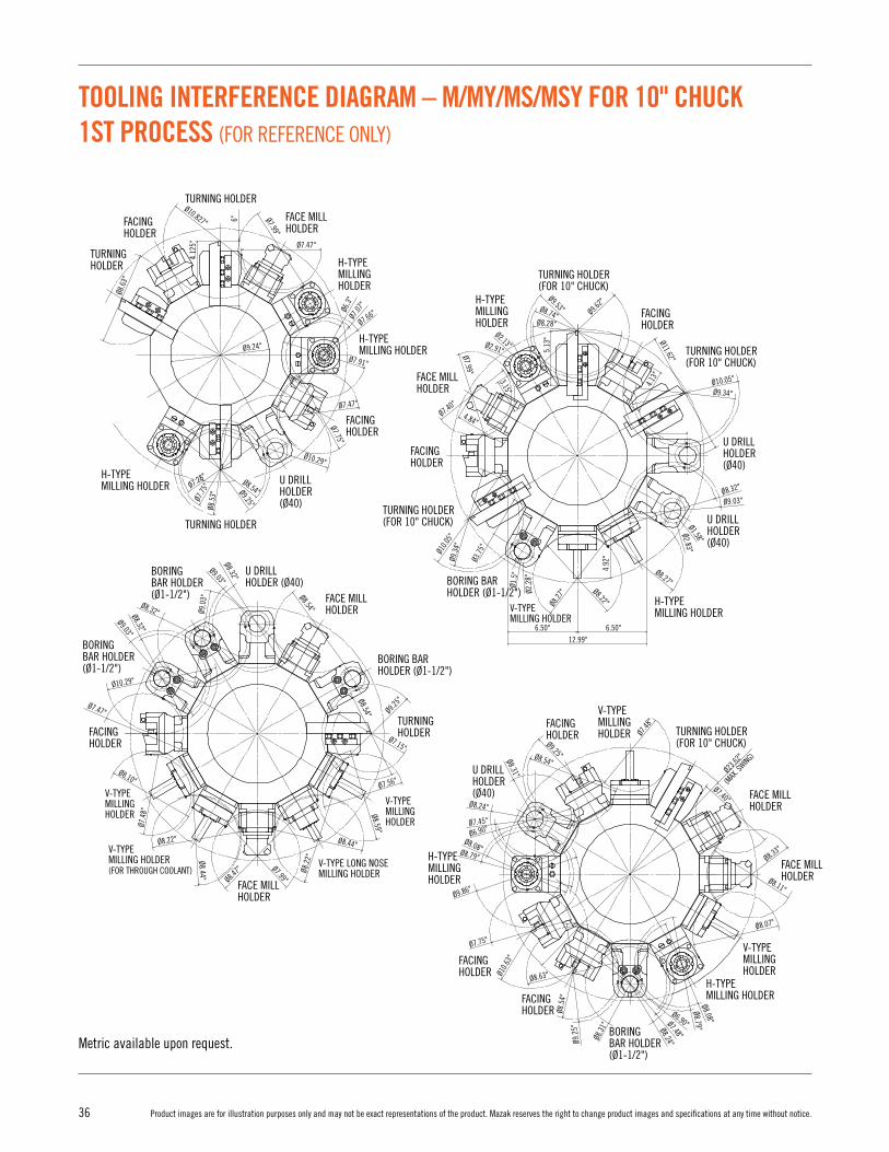
TOOLING INTERFERENCE DIAGRAM – M/MY/MS/MSY FOR 10" CHUCK 1ST PROCESS (FOR REFERENCE ONLY)
TOOL TIP LOCATION OF EACH TOOL
V-TYPE LONG NOSEMILLING HOLDER
V-TYPEMILLINGHOLDER
H-TYPEMILLING HOLDER
H-TYPEMILLING HOLDER
H-TYPE MILLING HOLDER
V-TYPE MILLING HOLDER
V-TYPE MILLING HOLDER (FOR THROUGH COOLANT)
U DRILL HOLDER (Ø40)
BORING BAR HOLDER (Ø1-1/2")
BORING BAR HOLDER(Ø1-1/2")
FACING HOLDER
FACE MILLHOLDER
FACE MILLHOLDER
FACINGHOLDER
FACINGHOLDER
FACINGHOLDER
FACE MILL HOLDER
TURNING HOLDER (FWD)
TURNING HOLDER (FOR 10" CHUCK)
4.12
5"4.
125"
5.12
5"
3.15
"
3.15
"2.
244"
2.67
7"2.
48"
2.44
1"3.
346"
3.26
8"1.
575"
1.57
5"
4.92
1"4.
921"
4.92
1"4.
843"
3.75
"
3.93
7"1.
188"
0.97
5"
Ø1.5
75"
Ø2.9
13"
Ø2.1
26"
3.75
"
Ø2.2
83"
2.77"6"
Ø10.29"
Ø8.54"
Ø2.83"Ø1.58"
Ø9.03"Ø8.32"
Ø9.34"
Ø9.53"Ø8.74"Ø8.28"
5.13
"Ø2.13"Ø2.91"Ø7.99"
3.15"
Ø7.40"
4.84"
Ø10.05"
Ø9.62"
Ø11.62"
Ø10.0
5"Ø9
.34"
Ø3.75
"
Ø1.5
"
Ø2.2
8"
Ø8.27
"Ø8.27"
Ø9.25"
Ø7.48
"
Ø23.62
"
(MAX
. SWING)
Ø7.40"
Ø8.54"Ø8.31"
Ø8.24"
Ø7.45"
Ø6.90"Ø8.08"Ø8.79"
Ø9.86"
Ø7.75"
Ø10.6
3"
Ø8.63"
Ø8.33"
Ø8.11"
Ø8.07"
Ø9.2
5"
Ø8.31
" Ø8.24"Ø7.48"
Ø6.90"
Ø8.79"Ø8.08"
Ø8.5
4"
Ø8.22"
Ø9.25"
Ø7.28"
Ø7.75
"Ø8
.53"
Ø6.3
"Ø7
.07"
Ø7.47"
Ø7.75"
Ø7.91"
Ø7.66"
Ø9.24"
Ø8.6
3"
Ø7.47"
Ø7.99"
Ø10.827"
4.12
5"
2.77"
2.77"
2.52"6" (MAX)
2.77"
2.77"
2.77"
2.77"
Ø0.787"
Ø0.787"
Ø1.969"
Ø0.787"
Ø1.5
"
Ø2.2
83"
0.5"
0.591"
0.644"
0.644"
0.644"
0.644"
0.311"0.74"
1.46"5.594"
1"
6" (MAX)
8.364" (MAX)
2.52" 2.52"
2.77"5.63"0.25"
0.25"
0.25"
H-TYPE MILLING HOLDER
H-TYPE MILLING HOLDER
H-TYPE MILLING HOLDER
H-TYPE MILLING HOLDER
V-TYPE MILLINGHOLDER
V-TYPE MILLING HOLDER
H-TYPE MILLING HOLDER U DRILL
HOLDER (Ø40)
U DRILL HOLDER (Ø40)
U DRILL HOLDER (Ø40)
U DRILL HOLDER (Ø40)
FACINGHOLDER
FACINGHOLDER
FACINGHOLDER
FACE MILLHOLDER
FACINGHOLDER
FACE MILL HOLDER
TURNING HOLDERTURNING HOLDER(FOR 10" CHUCK)
BORING BAR HOLDER (Ø1-1/2")
BORING BAR HOLDER (Ø1-1/2")
BORING BAR HOLDER (Ø1-1/2")
BORING BAR HOLDER (Ø1-1/2")
Ø8.54"
Ø8.32"
Ø8.32"Ø8.32"
Ø9.03"
Ø10.29"
Ø8.10"
Ø8.22"
Ø8.44"
Ø8.47" Ø7.99"
Ø8.2
2"
Ø7.4
8"
Ø7.47"
Ø9.0
3"
Ø9.03"
Ø8.54"
Ø7.15"
Ø7.56"
Ø8.59"
Ø8.44"
Ø9.25"
V-TYPE MILLING HOLDER
V-TYPE MILLING HOLDER(FOR THROUGH COOLANT)
V-TYPE MILLING HOLDER
V-TYPE LONG NOSE MILLING HOLDER
U DRILL HOLDER (Ø40)
FACINGHOLDER
FACE MILLHOLDER
FACE MILLHOLDER
TURNINGHOLDER
TURNING HOLDER(FOR 10" CHUCK)
TURNING HOLDER(FOR 10" CHUCK)
TURNING HOLDER(FOR 10" CHUCK)
TURNING HOLDER
TURNINGHOLDER
6.50" 6.50"
4.92
"
4.13"
12.99"
Metric available upon request.

37Product images are for illustration purposes only and may not be exact representations of the product. Mazak reserves the right to change product images and specifications at any time without notice.
TOOLING INTERFERENCE DIAGRAM
TOOLING INTERFERENCE DIAGRAM – M/MY/MS/MSY FOR 10" CHUCK 1ST PROCESS (FOR REFERENCE ONLY)
TOOLING INTERFERENCE DIAGRAM – M/MY/MS/MSY FOR 10" CHUCK 1ST PROCESS (FOR REFERENCE ONLY)
TOOL TIP LOCATION OF EACH TOOL
V-TYPE LONG NOSEMILLING HOLDER
V-TYPEMILLINGHOLDER
H-TYPEMILLING HOLDER
H-TYPEMILLING HOLDER
H-TYPE MILLING HOLDER
V-TYPE MILLING HOLDER
V-TYPE MILLING HOLDER (FOR THROUGH COOLANT)
U DRILL HOLDER (Ø40)
BORING BAR HOLDER (Ø1-1/2")
BORING BAR HOLDER(Ø1-1/2")
FACING HOLDER
FACE MILLHOLDER
FACE MILLHOLDER
FACINGHOLDER
FACINGHOLDER
FACINGHOLDER
FACE MILL HOLDER
TURNING HOLDER (FWD)
TURNING HOLDER (FOR 10" CHUCK)
4.12
5"4.
125"
5.12
5"
3.15
"
3.15
"2.
244"
2.67
7"2.
48"
2.44
1"3.
346"
3.26
8"1.
575"
1.57
5"
4.92
1"4.
921"
4.92
1"4.
843"
3.75
"
3.93
7"1.
188"
0.97
5"
Ø1.5
75"
Ø2.9
13"
Ø2.1
26"
3.75
"
Ø2.2
83"
2.77"6"
Ø10.29"
Ø8.54"
Ø2.83"Ø1.58"
Ø9.03"Ø8.32"
Ø9.34"
Ø9.53"Ø8.74"Ø8.28"
5.13
"Ø2.13"Ø2.91"Ø7.99"
3.15"
Ø7.40"
4.84"
Ø10.05"
Ø9.62"
Ø11.62"
Ø10.0
5"Ø9
.34"
Ø3.75
"
Ø1.5
"
Ø2.2
8"
Ø8.27
"
Ø8.27"
Ø9.25"
Ø7.48
"
Ø23.62
"
(MAX
. SWING)
Ø7.40"
Ø8.54"Ø8.31"
Ø8.24"
Ø7.45"
Ø6.90"Ø8.08"Ø8.79"
Ø9.86"
Ø7.75"
Ø10.6
3"
Ø8.63"
Ø8.33"
Ø8.11"
Ø8.07"
Ø9.2
5"
Ø8.31
" Ø8.24"Ø7.48"
Ø6.90"
Ø8.79"Ø8.08"
Ø8.5
4"
Ø8.22"
Ø9.25"
Ø7.28"
Ø7.75
"Ø8
.53"
Ø6.3
"Ø7
.07"
Ø7.47"
Ø7.75"
Ø7.91"
Ø7.66"
Ø9.24"
Ø8.6
3"
Ø7.47"
Ø7.99"
Ø10.827"
4.12
5"
2.77"
2.77"
2.52"6" (MAX)
2.77"
2.77"
2.77"
2.77"
Ø0.787"
Ø0.787"
Ø1.969"
Ø0.787"
Ø1.5
"
Ø2.2
83"
0.5"
0.591"
0.644"
0.644"
0.644"
0.644"
0.311"0.74"
1.46"5.594"
1"
6" (MAX)
8.364" (MAX)
2.52" 2.52"
2.77"5.63"0.25"
0.25"
0.25"
H-TYPE MILLING HOLDER
H-TYPE MILLING HOLDER
H-TYPE MILLING HOLDER
H-TYPE MILLING HOLDER
V-TYPE MILLINGHOLDER
V-TYPE MILLING HOLDER
H-TYPE MILLING HOLDER U DRILL
HOLDER (Ø40)
U DRILL HOLDER (Ø40)
U DRILL HOLDER (Ø40)
U DRILL HOLDER (Ø40)
FACINGHOLDER
FACINGHOLDER
FACINGHOLDER
FACE MILLHOLDER
FACINGHOLDER
FACE MILL HOLDER
TURNING HOLDERTURNING HOLDER(FOR 10" CHUCK)
BORING BAR HOLDER (Ø1-1/2")
BORING BAR HOLDER (Ø1-1/2")
BORING BAR HOLDER (Ø1-1/2")
BORING BAR HOLDER (Ø1-1/2")
Ø8.54"
Ø8.32"
Ø8.32"Ø8.32"
Ø9.03"
Ø10.29"
Ø8.10"
Ø8.22"
Ø8.44"
Ø8.47" Ø7.99"
Ø8.2
2"
Ø7.4
8"
Ø7.47"
Ø9.0
3"
Ø9.03"
Ø8.54"
Ø7.15"
Ø7.56"
Ø8.59"
Ø8.44"
Ø9.25"
V-TYPE MILLING HOLDER
V-TYPE MILLING HOLDER(FOR THROUGH COOLANT)
V-TYPE MILLING HOLDER
V-TYPE LONG NOSE MILLING HOLDER
U DRILL HOLDER (Ø40)
FACINGHOLDER
FACE MILLHOLDER
FACE MILLHOLDER
TURNINGHOLDER
TURNING HOLDER(FOR 10" CHUCK)
TURNING HOLDER(FOR 10" CHUCK)
TURNING HOLDER(FOR 10" CHUCK)
TURNING HOLDER
TURNINGHOLDER
6.50" 6.50"
4.92
"
4.13"
12.99"
Metric available upon request.

38 Product images are for illustration purposes only and may not be exact representations of the product. Mazak reserves the right to change product images and specifications at any time without notice.
TOOLING INTERFERENCE DIAGRAM – M/MY/MS/MSY FOR 10" CHUCK 1ST PROCESS (FOR REFERENCE ONLY)
TOOL TIP LOCATION OF EACH TOOL
MAIN SPINDLE
V-TYPE LONG NOSEMILLING HOLDER
V-TYPEMILLING HOLDER
V-TYPE MILLING HOLDER(FOR THROUGH COOLANT)
V-TYPE MILLING HOLDER
V-TYPE LONG NOSEMILLING HOLDER
V-TYPE LONG NOSEMILLING HOLDER
V-TYPE LONG NOSEMILLING HOLDER
H-TYPE BACK MILLING HOLDER
H-TYPE MILLING HOLDER
H-TYPE BACK MILLING HOLDER
H-TYPE BACK MILLING HOLDER
H-TYPE MILLING HOLDER
H-TYPE BACK MILLING HOLDER
H-TYPE BACK MILLING HOLDER
H-TYPE BACK MILLING HOLDER
H-TYPE BACK MILLING HOLDER
H-TYPE BACK MILLING HOLDER
H-TYPE BACK MILLING HOLDER
H-TYPE BACK MILLING HOLDER
H-TYPEMILLING HOLDER
V-TYPEMILLING HOLDER
V-TYPEMILLING HOLDER
V-TYPE MILLING HOLDER (FOR THROUGH COOLANT)
BORING BAR HOLDER (Ø40)
SS BORING BAR HOLDER
SS BORING BAR HOLDER
BORING BAR HOLDER (Ø40)
SS BORING BAR HOLDER
SS BORING BAR HOLDER
FACING HOLDER
FACING HOLDER
FACING HOLDER
FACING HOLDER
CUT-OFF HOLDER
CUT-OFF HOLDER
CUT-OFFHOLDER
CUT-OFFHOLDER
SS TURNING HOLDER
SS TURNINGHOLDER
SS TURNINGHOLDER
SS TURNING HOLDER
SS TURNINGHOLDER
Ø10.
65"Ø6.1
8"
Ø10.83"Ø7.44"
Ø1.5" Ø2.28"
4.88"
5.32
" 3.75"
5.13"
Ø7.48"
Ø6.06"
Ø6.06"
Ø2.76"
Ø6.06"
4"Ø9.87"
Ø9.01"
Ø9.06"
Ø2.28"
Ø7.03"
Ø7.09"
Ø7.91"
Ø8.16
"
Ø10.65"
Ø8.52"
Ø9.93"
Ø8.39"
Ø6.18"Ø8"
Ø1"
Ø1"
3.94"
4.92"
Ø7.4
4"
3.34
"
Ø1"
2.48
"
Ø7.15"3.15"
Ø9.56"
Ø8.27"
Ø11.62"
3.15"
Ø6.06"
Ø6.06"
Ø7.95"
Ø6.78"
Ø7.9
6"
Ø8.46
"Ø9
.25"
Ø9.3
4"
Ø10.13
"
Ø9.62"
4.5"
3.54"
3.54"
3.47
"
3.54"
Ø6.06"
Ø0.79"
Ø23.62"(MAX INDEXING DIAMETER)
Ø23.62"
(MAX INDEXING DIAMETER)
Ø23.62"
(MAX INDEXING DIAMETER)
Ø23.62"
(MAX INDEXING DIAMETER)
4"
3.94"
Ø1"
5.12
5"
4.12
5"
5.12
5"0.
909"
0.51
2"1.
181"
4.88
2"4.
882"
4.92
1"
5.31
5"
2.24
4"2.
638"
2.48
"2.
402"
3.34
6"1.
575"
3.93
7"
3.54
3"
1.18
1"
3.75
"3.
15"
4"
2.77"
2.77"
2.77"
2.77"
Ø0.787"
0.644"
2.77" 3.605"
Ø0.787"
0.644"
2.77"
Ø0.787"
0.644"
5.594"
8.364" (MAX)
1.46"
2.77"
2.52"6" (MAX)
0.5"
3.605" 2.77" 3.605"
2.625"
0.145"
0.419" 3.846" (MAX)
2.255"
3.875"
4"
1.25"
2.5" (MAX)
2.913"
2.913"
0.25"
0.25" 2.52"
0.25"
0.591"
0.298"
0.298"
0.298"
0.25"
1"
Ø1"
Ø1.5
"
Ø2.2
83"
BORING BAR HOLDER (Ø40)
BORING BAR HOLDER (Ø40) SS BORING
BAR HOLDER
SS BORING BAR HOLDER
SS TURNING HOLDER
SS BORING BAR HOLDER
SS BORING BAR HOLDER
Metric available upon request.

39Product images are for illustration purposes only and may not be exact representations of the product. Mazak reserves the right to change product images and specifications at any time without notice.
TOOLING INTERFERENCE DIAGRAM
TOOLING INTERFERENCE DIAGRAM – M/MY/MS/MSY FOR 10" CHUCK 1ST PROCESS (FOR REFERENCE ONLY)
TOOLING INTERFERENCE DIAGRAM – M/MY/MS/MSY FOR 10" CHUCK 1ST PROCESS (FOR REFERENCE ONLY)
TOOL TIP LOCATION OF EACH TOOL
MAIN SPINDLE
V-TYPE LONG NOSEMILLING HOLDER
V-TYPEMILLING HOLDER
V-TYPE MILLING HOLDER(FOR THROUGH COOLANT)
V-TYPE MILLING HOLDER
V-TYPE LONG NOSEMILLING HOLDER
V-TYPE LONG NOSEMILLING HOLDER
V-TYPE LONG NOSEMILLING HOLDER
H-TYPE BACK MILLING HOLDER
H-TYPE MILLING HOLDER
H-TYPE BACK MILLING HOLDER
H-TYPE BACK MILLING HOLDER
H-TYPE MILLING HOLDER
H-TYPE BACK MILLING HOLDER
H-TYPE BACK MILLING HOLDER
H-TYPE BACK MILLING HOLDER
H-TYPE BACK MILLING HOLDER
H-TYPE BACK MILLING HOLDER
H-TYPE BACK MILLING HOLDER
H-TYPE BACK MILLING HOLDER
H-TYPEMILLING HOLDER
V-TYPEMILLING HOLDER
V-TYPEMILLING HOLDER
V-TYPE MILLING HOLDER (FOR THROUGH COOLANT)
BORING BAR HOLDER (Ø40)
SS BORING BAR HOLDER
SS BORING BAR HOLDER
BORING BAR HOLDER (Ø40)
SS BORING BAR HOLDER
SS BORING BAR HOLDER
FACING HOLDER
FACING HOLDER
FACING HOLDER
FACING HOLDER
CUT-OFF HOLDER
CUT-OFF HOLDER
CUT-OFFHOLDER
CUT-OFFHOLDER
SS TURNING HOLDER
SS TURNINGHOLDER
SS TURNINGHOLDER
SS TURNING HOLDER
SS TURNINGHOLDER
Ø10.
65"Ø6.1
8"
Ø10.83"Ø7.44"
Ø1.5" Ø2.28"
4.88"
5.32
" 3.75"
5.13"
Ø7.48"
Ø6.06"
Ø6.06"
Ø2.76"
Ø6.06"
4"Ø9.87"
Ø9.01"
Ø9.06"
Ø2.28"
Ø7.03"
Ø7.09"
Ø7.91"
Ø8.16
"
Ø10.65"
Ø8.52"
Ø9.93"
Ø8.39"
Ø6.18"Ø8"
Ø1"
Ø1"
3.94"
4.92"
Ø7.4
4"
3.34
"
Ø1"
2.48
"
Ø7.15"3.15"
Ø9.56"
Ø8.27"
Ø11.62"
3.15"
Ø6.06"
Ø6.06"
Ø7.95"
Ø6.78"
Ø7.9
6"
Ø8.46
"Ø9
.25"
Ø9.3
4"
Ø10.13
"
Ø9.62"
4.5"
3.54"
3.54"
3.47
"
3.54"
Ø6.06"
Ø0.79"
Ø23.62"(MAX INDEXING DIAMETER)
Ø23.62"
(MAX INDEXING DIAMETER)
Ø23.62"
(MAX INDEXING DIAMETER)
Ø23.62"
(MAX INDEXING DIAMETER)
4"
3.94"
Ø1"
5.12
5"
4.12
5"
5.12
5"0.
909"
0.51
2"1.
181"
4.88
2"4.
882"
4.92
1"
5.31
5"
2.24
4"2.
638"
2.48
"2.
402"
3.34
6"1.
575"
3.93
7"
3.54
3"
1.18
1"
3.75
"3.
15"
4"
2.77"
2.77"
2.77"
2.77"
Ø0.787"
0.644"
2.77" 3.605"
Ø0.787"
0.644"
2.77"
Ø0.787"
0.644"
5.594"
8.364" (MAX)
1.46"
2.77"
2.52"6" (MAX)
0.5"
3.605" 2.77" 3.605"
2.625"
0.145"
0.419" 3.846" (MAX)
2.255"
3.875"
4"
1.25"
2.5" (MAX)
2.913"
2.913"
0.25"
0.25" 2.52"
0.25"
0.591"
0.298"
0.298"
0.298"
0.25"
1"
Ø1"
Ø1.5
"
Ø2.2
83"
BORING BAR HOLDER (Ø40)
BORING BAR HOLDER (Ø40) SS BORING
BAR HOLDER
SS BORING BAR HOLDER
SS TURNING HOLDER
SS BORING BAR HOLDER
SS BORING BAR HOLDER
Metric available upon request.
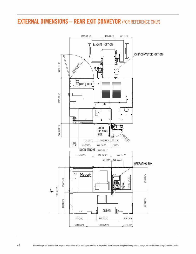
40 Product images are for illustration purposes only and may not be exact representations of the product. Mazak reserves the right to change product images and specifications at any time without notice.
EXTERNAL DIMENSIONS – REAR EXIT CONVEYOR (FOR REFERENCE ONLY)
(OPTION)CHIP CONVEYOR
POWER INLET
AIR INLET (OPTION)
OPERATING BOX
SIGNAL TOWER (OPTION)
CHIP CONVEYOR (OPTION)
DOOR OPENING SIZE
DOOR STROKE
CONTROL BOX
BUCKET (OPTION)
A
BUCKET (OPTION)
FLOOR REQUIRED FOR OILPAN REMOVAL
FLOOR REQUIRED FOR OILPAN REMOVAL
CONTROLBOX
B VIEW
A VIEW
OILPAN
CONTROL BOX
OILPAN
B
R878
.6 (34
.6")
1226 (48.3") 661 (26")
548.8 (21.6")
925
(36.
4")
800
(31.
5")
1925
(75.
8") 13
64.3
(5
3.7"
)
379.
8 (1
5")
200
(7.9
")
1219
.2 (4
8")
1510
.4 (5
9.5"
)
750
(29.
5")
291.
2 (1
1.5"
)
1500
(59.
1")
1020
(40.
2")
705
(27.
7")
1010
(39.
8")
10 (0
.4")
665
(26.
2")
40 (1
.5")
250
(9.8
")
225
(8.8
")
855
(33.
7")
891.2 (35.1") 900 (35.4")
1747 (68.8")
1135 (44.7")
610 (24")
555 (21.8")
1690 (66.5")
400 (15.7") 900 (35.4")
930 (36.6") 760 (29.9")
390 (15.4")
57 (2.3")
540 (21.2")
*3006.5 (118.3")#2998.5 (118") 1680 (66.2")
*262 (10.3")#254 (10") 2744.5 (108") 375.5 (14.8")
776 (30.5") 914 (36") 1054.5 (41.5")
60 (2.4") 1300 (51.2") 400 (15.7")
117.4 (4.6") 570 (22.4") 860 (33.9")
780 (30.7") 1020 (40.2")
340 (13.4") 530 (20.9")
138 (5.4") 33 (1.3")499 (19.6")
668 (26.3")
2340 (92.1)"
870 (34.3")
990 (39") 840 (33.1") 510 (20")
640 (25.2") 1330 (52.4") 370 (14.5")
9.8 (0.4") 435 (17.1")
670 (26.3") 800 (31.5")
2 (0.1")
862.
2 (3
3.9"
)16
90 (6
6.5"
)50
6.3
(19.
9")
925
(36.
4")
1725
(67.
9")
851
(33.
5")
874
(34.
4")
624.
92 (2
4.6"
)
800
(31.
5")
R406.2 (16")
453 (17.8")

41Product images are for illustration purposes only and may not be exact representations of the product. Mazak reserves the right to change product images and specifications at any time without notice.
EXTERNAL DIMENSIONS
EXTERNAL DIMENSIONS – REAR EXIT CONVEYOR (FOR REFERENCE ONLY)
(OPTION)CHIP CONVEYOR
POWER INLET
AIR INLET (OPTION)
OPERATING BOX
SIGNAL TOWER (OPTION)
CHIP CONVEYOR (OPTION)
DOOR OPENING SIZE
DOOR STROKE
CONTROL BOX
BUCKET (OPTION)
A
BUCKET (OPTION)
FLOOR REQUIRED FOR OILPAN REMOVAL
FLOOR REQUIRED FOR OILPAN REMOVAL
CONTROLBOX
B VIEW
A VIEW
OILPAN
CONTROL BOX
OILPAN
B
R878
.6 (34
.6")
1226 (48.3") 661 (26")
548.8 (21.6")
925
(36.
4")
800
(31.
5")
1925
(75.
8") 13
64.3
(5
3.7"
)
379.
8 (1
5")
200
(7.9
")
1219
.2 (4
8")
1510
.4 (5
9.5"
)
750
(29.
5")
291.
2 (1
1.5"
)
1500
(59.
1")
1020
(40.
2")
705
(27.
7")
1010
(39.
8")
10 (0
.4")
665
(26.
2")
40 (1
.5")
250
(9.8
")
225
(8.8
")
855
(33.
7")
891.2 (35.1") 900 (35.4")
1747 (68.8")
1135 (44.7")
610 (24")
555 (21.8")
1690 (66.5")
400 (15.7") 900 (35.4")
930 (36.6") 760 (29.9")
390 (15.4")
57 (2.3")
540 (21.2")
*3006.5 (118.3")#2998.5 (118") 1680 (66.2")
*262 (10.3")#254 (10") 2744.5 (108") 375.5 (14.8")
776 (30.5") 914 (36") 1054.5 (41.5")
60 (2.4") 1300 (51.2") 400 (15.7")
117.4 (4.6") 570 (22.4") 860 (33.9")
780 (30.7") 1020 (40.2")
340 (13.4") 530 (20.9")
138 (5.4") 33 (1.3")499 (19.6")
668 (26.3")
2340 (92.1)"
870 (34.3")
990 (39") 840 (33.1") 510 (20")
640 (25.2") 1330 (52.4") 370 (14.5")
9.8 (0.4") 435 (17.1")
670 (26.3") 800 (31.5")
2 (0.1")
862.
2 (3
3.9"
)16
90 (6
6.5"
)50
6.3
(19.
9")
925
(36.
4")
1725
(67.
9")
851
(33.
5")
874
(34.
4")
624.
92 (2
4.6"
)
800
(31.
5")
R406.2 (16")
453 (17.8")

42 Product images are for illustration purposes only and may not be exact representations of the product. Mazak reserves the right to change product images and specifications at any time without notice.
EXTERNAL DIMENSIONS – SIDE EXIT CONVEYOR (FOR REFERENCE ONLY)
POWER INLET
548.8 (21.6") 1151.2 (45.4") 900 (35.4")
800 (31.5") 780 (30.7") 1020 (40.2")
40 (1
.5")
10 (0
.4")
665
(26.
2")
1010
(39.
8")
800
(31.
5")
925
(36.
4")
705
(27.
7")
1020
(40.
2")
390 (15.4")900 (35.4")400 (15.7")
760 (29.9")930 (36.6")
250
(9.8
")
57 (2.3")
1747 (68.8")
1690 (66.5")
555 (21.8")1135 (44.7")
1500
(59.
1")
853
(33.
7")
225
(18.
8")
CONTROLBOX
B VIEWA VIEW
OILPAN
CONTROL BOX
OPERATING BOX
BUCKET (OPTION)
CHIP CONVEYOR (OPTION)
FLOOR REQUIRED FOR CHIP CONVEYOR REMOVAL
870 (34.3") 840 (33.1")
10 (0.4")
890 (35")
640 (25.2") 1330 (52.4") 630 (24.8")
990 (39") 840 (33.1") 770 (30.3")
2600 (102.4") 1158 (45.6") 1570 (61.8")
925
(36.
4")
800
(31.
5")
#874
(34.
4")
*755
(29.
8")
*969
(38.
1")
750
(29.
5")
#851
(33.
5")
1244
(49"
)29
1 (1
1.4"
)
1535
(60.
4")
1725
(67.
9")
OILPAN
B
CYLINDERCOVER
624.
92 (2
4.6"
)
AIR INLET(OPTION)
SIGNAL TOWER (OPTION)
# 254 (10")# 262 (10.3")
141.4 (5.6")
776 (30.5")
#1944 (76.5")#1952 (76.8")
1300 (51.2")380 (15")60 (2.4")
914 (36")
200
(7.9
")
1349
.3 (5
3.1"
)
1925
(75.
8")
FLOOR REQUIRED FOR OILPAN REMOVAL
FLOO
R RE
QUIR
ED F
OROI
LPAN
REM
OVAL
379.
8 (1
5")
CHIP CONVEYOR (OPTION)
BUCKET (OPTION)
33 (1.3")639 (25.2")168 (6.6")200
(7.9") 670 (26.4")
860 (33.9")
838 (33") 2 (0.1")
R406.2 (16")
505.
8 (1
9.9"
)86
2.2
(33.
9")
1690
(66.
5")
1680
(66.
2")
400
(15.
7")
1086
(42.
8")
1260
(49.
6")
151
(5.9
")45
3 (1
7.8"
)
R878.6
(34.6
")
DOOR STROKE
DOOROPENING SIZE
CONTROL BOX
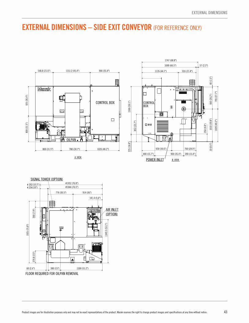
43Product images are for illustration purposes only and may not be exact representations of the product. Mazak reserves the right to change product images and specifications at any time without notice.
EXTERNAL DIMENSIONS
EXTERNAL DIMENSIONS – SIDE EXIT CONVEYOR (FOR REFERENCE ONLY)
POWER INLET
548.8 (21.6") 1151.2 (45.4") 900 (35.4")
800 (31.5") 780 (30.7") 1020 (40.2")
40 (1
.5")
10 (0
.4")
665
(26.
2")
1010
(39.
8")
800
(31.
5")
925
(36.
4")
705
(27.
7")
1020
(40.
2")
390 (15.4")900 (35.4")400 (15.7")
760 (29.9")930 (36.6")
250
(9.8
")
57 (2.3")
1747 (68.8")
1690 (66.5")
555 (21.8")1135 (44.7")
1500
(59.
1")
853
(33.
7")
225
(18.
8")
CONTROLBOX
B VIEWA VIEW
OILPAN
CONTROL BOX
OPERATING BOX
BUCKET (OPTION)
CHIP CONVEYOR (OPTION)
FLOOR REQUIRED FOR CHIP CONVEYOR REMOVAL
870 (34.3") 840 (33.1")
10 (0.4")
890 (35")
640 (25.2") 1330 (52.4") 630 (24.8")
990 (39") 840 (33.1") 770 (30.3")
2600 (102.4") 1158 (45.6") 1570 (61.8")
925
(36.
4")
800
(31.
5")
#874
(34.
4")
*755
(29.
8")
*969
(38.
1")
750
(29.
5")
#851
(33.
5")
1244
(49"
)29
1 (1
1.4"
)
1535
(60.
4")
1725
(67.
9")
OILPAN
B
CYLINDERCOVER
624.
92 (2
4.6"
)
AIR INLET(OPTION)
SIGNAL TOWER (OPTION)
# 254 (10")# 262 (10.3")
141.4 (5.6")
776 (30.5")
#1944 (76.5")#1952 (76.8")
1300 (51.2")380 (15")60 (2.4")
914 (36")
200
(7.9
")
1349
.3 (5
3.1"
)
1925
(75.
8")
FLOOR REQUIRED FOR OILPAN REMOVAL
FLOO
R RE
QUIR
ED F
OROI
LPAN
REM
OVAL
379.
8 (1
5")
CHIP CONVEYOR (OPTION)
BUCKET (OPTION)
33 (1.3")639 (25.2")168 (6.6")200
(7.9") 670 (26.4")
860 (33.9")
838 (33") 2 (0.1")
R406.2 (16")
505.
8 (1
9.9"
)86
2.2
(33.
9")
1690
(66.
5")
1680
(66.
2")
400
(15.
7")
1086
(42.
8")
1260
(49.
6")
151
(5.9
")45
3 (1
7.8"
)
R878.6
(34.6
")
DOOR STROKE
DOOROPENING SIZE
CONTROL BOX

44 Product images are for illustration purposes only and may not be exact representations of the product. Mazak reserves the right to change product images and specifications at any time without notice.
MACHINE SPECIFICATIONS – QTU-200 SERIES
QTU-200 QTU-200M QTU-200MS
Bed length 500U 500U 500U
Capacity
Maximum swing in (mm) 27.4 (695)
Recommended turning diameter in (mm) 8.35 (212)
Maximum turning diameter in (mm) 16.25 (410) 13.5 (340)
1st spindle chuck size in 6/8
2nd spindle chuck size in N/A 5
Bar working diameter in (mm) 1.65 (42)
Main spindle
Maximum speed rpm 6,000
Spindle nose ASA JIS A2-6
Spindle through hole in (mm) 2.4 (61)
Second spindle
Maximum speed rpm N/A 6,000
Spindle nose FLAT N/A JIS A2-5
Spindle through hole in (mm) N/A 2.4 (61)
Turret
Number of tools – 12
OD tool size in (mm) 1 (25)
Maximum boring bar size in (mm) 1.5 (40)
Rotary drill in (mm) 0.75 (20)
Rotary tap – M20
Rotary endmill in (mm) 0.75 (20)
Turret indexing time (1 station swivel) s 0.18 0.19
Maximum rotary tool speed rpm 4,500 (Option: 6,000)
TailstockQuill bore taper MT MT No. 5 N/A
Quill travel in (mm) 13.250 (340) N/A
Feed axes
Travel (X axis) in (mm) 8.5 (215)
Travel (Y axis) in (mm) N/A
Travel (Z axis) in (mm) 24.5 (625) 23.75 (605)
Feed rate
Rapid traverse rate (X axis) ipm (m/min) 1,181 (30)
Rapid traverse rate (Y axis) in (mm) N/A
Rapid traverse rate (Z axis) ipm (m/min) 1,417 (36)
MotorsMain spindle motor power hp (kW) 20 (40% ED)/15 (Cont.) [15 (40% ED)/11 (Cont.)]
Rotary tool motor power hp (kW) N/A 7.3 (5.5)
Power source Electric power supply (rated capacity) kVA 27.8 27.7 27.5
Machine dimensions
Height in (mm) 67.9 (1,725)
Width in (mm) 66.5 (1,690)
Length in (mm) 102.4 (2,600)
Weight Ibs (kg) 11,244 (5,100) 11,464 (5,200) 11,685 (5,300)

45Product images are for illustration purposes only and may not be exact representations of the product. Mazak reserves the right to change product images and specifications at any time without notice.
MACHINE SPECIFICATIONS
QTU-200MY QTU-200MSY
Bed length 500U 500U
Capacity
Maximum swing in (mm) 27.4 (695)
Recommended turning diameter in (mm) 8.35 (212)
Maximum turning diameter in (mm) 13.5 (340)
1st spindle chuck size in 6/8
2nd spindle chuck size in N/A 5
Bar working diameter in (mm) 1.65 (42)
Main spindle
Maximum speed rpm 6,000
Spindle nose ASA JIS A2-6
Spindle through hole in (mm) 2.4 (61)
Second spindle
Maximum speed rpm 6,000
Spindle nose FLAT JIS A2-5
Spindle through hole in (mm) 2.4 (61)
Turret
Number of tools – 12
OD tool size in (mm) 1 (25)
Maximum boring bar size in (mm) 1.5 (40)
Rotary drill in (mm) 0.75 (20)
Rotary tap – M20
Rotary endmill in (mm) 0.75 (20)
Turret indexing time (1 station swivel) s 0.19
Maximum rotary tool speed rpm 4,500 (Option: 6,000)
TailstockQuill bore taper MT MT No. 5 N/A
Quill travel in (mm) 13.250 (340) N/A
Feed axes
Travel (X axis) in (mm) 8.5 (215)
Travel (Y axis) in (mm) 4 (100)
Travel (Z axis) in (mm) 23.75 (605)
Feed rate
Rapid traverse rate (X axis) ipm (m/min) 1,181 (30)
Rapid traverse rate (Y axis) in (mm) 10 (394)
Rapid traverse rate (Z axis) ipm (m/min) 1,417 (36)
MotorsMain spindle motor power hp (kW) 20 (40% ED)/15 (Cont.) [15 (40% ED)/11 (Cont.)]
Rotary tool motor power hp (kW) 7.3 (5.5)
Power source Electric power supply (rated capacity) kVA 29 28.5
Machine dimensions
Height in (mm) 67.9 (1,725)
Width in (mm) 66.5 (1,690)
Length in (mm) 102.4 (2,600)
Weight Ibs (kg) 11,905 (5,400) 12,125 (5,500)
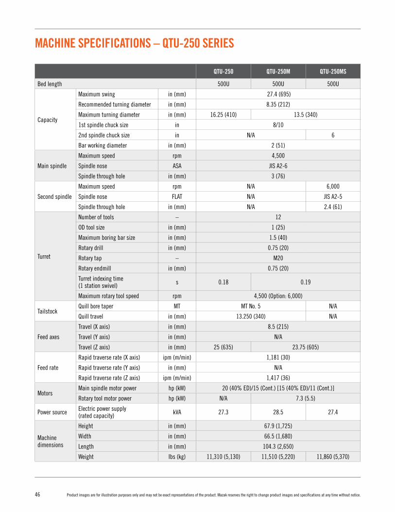
46 Product images are for illustration purposes only and may not be exact representations of the product. Mazak reserves the right to change product images and specifications at any time without notice.
MACHINE SPECIFICATIONS – QTU-250 SERIES
QTU-250 QTU-250M QTU-250MS
Bed length 500U 500U 500U
Capacity
Maximum swing in (mm) 27.4 (695)
Recommended turning diameter in (mm) 8.35 (212)
Maximum turning diameter in (mm) 16.25 (410) 13.5 (340)
1st spindle chuck size in 8/10
2nd spindle chuck size in N/A 6
Bar working diameter in (mm) 2 (51)
Main spindle
Maximum speed rpm 4,500
Spindle nose ASA JIS A2-6
Spindle through hole in (mm) 3 (76)
Second spindle
Maximum speed rpm N/A 6,000
Spindle nose FLAT N/A JIS A2-5
Spindle through hole in (mm) N/A 2.4 (61)
Turret
Number of tools – 12
OD tool size in (mm) 1 (25)
Maximum boring bar size in (mm) 1.5 (40)
Rotary drill in (mm) 0.75 (20)
Rotary tap – M20
Rotary endmill in (mm) 0.75 (20)
Turret indexing time (1 station swivel) s 0.18 0.19
Maximum rotary tool speed rpm 4,500 (Option: 6,000)
TailstockQuill bore taper MT MT No. 5 N/A
Quill travel in (mm) 13.250 (340) N/A
Feed axes
Travel (X axis) in (mm) 8.5 (215)
Travel (Y axis) in (mm) N/A
Travel (Z axis) in (mm) 25 (635) 23.75 (605)
Feed rate
Rapid traverse rate (X axis) ipm (m/min) 1,181 (30)
Rapid traverse rate (Y axis) in (mm) N/A
Rapid traverse rate (Z axis) ipm (m/min) 1,417 (36)
MotorsMain spindle motor power hp (kW) 20 (40% ED)/15 (Cont.) [15 (40% ED)/11 (Cont.)]
Rotary tool motor power hp (kW) N/A 7.3 (5.5)
Power source Electric power supply (rated capacity) kVA 27.3 28.5 27.4
Machine dimensions
Height in (mm) 67.9 (1,725)
Width in (mm) 66.5 (1,680)
Length in (mm) 104.3 (2,650)
Weight Ibs (kg) 11,310 (5,130) 11,510 (5,220) 11,860 (5,370)

47Product images are for illustration purposes only and may not be exact representations of the product. Mazak reserves the right to change product images and specifications at any time without notice.
MACHINE SPECIFICATIONS
QTU-250MY QTU-250MSY
Bed length 500U 500U
Capacity
Maximum swing in (mm) 27.4 (695)
Recommended turning diameter in (mm) 8.35 (212)
Maximum turning diameter in (mm) 13.5 (340)
1st spindle chuck size in 8/10
2nd spindle chuck size in N/A 6
Bar working diameter in (mm) 2 (51)
Main spindle
Maximum speed rpm 4,500
Spindle nose ASA JIS A2-6
Spindle through hole in (mm) 3 (76)
Second spindle
Maximum speed rpm N/A 6,000
Spindle nose FLAT N/A JIS A2-5
Spindle through hole in (mm) N/A 2.4 (61)
Turret
Number of tools – 12
OD tool size in (mm) 1 (25)
Maximum boring bar size in (mm) 1.5 (40)
Rotary drill in (mm) 0.75 (20)
Rotary tap – M20
Rotary endmill in (mm) 0.75 (20)
Turret indexing time (1 station swivel) s 0.19
Maximum rotary tool speed rpm 4,500 (Option: 6,000)
TailstockQuill bore taper MT MT No. 5 N/A
Quill travel in (mm) 13.250 (340) N/A
Feed axes
Travel (X axis) in (mm) 8.5 (215)
Travel (Y axis) in (mm) 4 (100)
Travel (Z axis) in (mm) 23.75 (605)
Feed rate
Rapid traverse rate (X axis) ipm (m/min) 1,181 (30)
Rapid traverse rate (Y axis) in (mm) 10 (394)
Rapid traverse rate (Z axis) ipm (m/min) 1,417 (36)
MotorsMain spindle motor power hp (kW) 20 (40% ED)/15 (Cont.) [15 (40% ED)/11 (Cont.)]
Rotary tool motor power hp (kW) 7.3 (5.5)
Power source Electric power supply (rated capacity) kVA 28.3 28.4
Machine dimensions
Height in (mm) 67.9 (1,725)
Width in (mm) 66.5 (1,680)
Length in (mm) 104.3 (2,650)
Weight Ibs (kg) 11,905 (5,400) 12,260 (5,560)
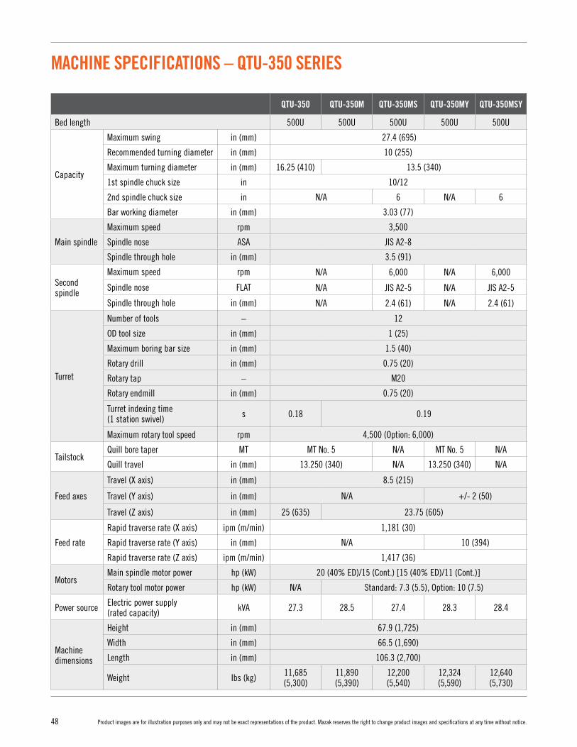
48 Product images are for illustration purposes only and may not be exact representations of the product. Mazak reserves the right to change product images and specifications at any time without notice.
MACHINE SPECIFICATIONS – QTU-350 SERIES
QTU-350 QTU-350M QTU-350MS QTU-350MY QTU-350MSY
Bed length 500U 500U 500U 500U 500U
Capacity
Maximum swing in (mm) 27.4 (695)
Recommended turning diameter in (mm) 10 (255)
Maximum turning diameter in (mm) 16.25 (410) 13.5 (340)
1st spindle chuck size in 10/12
2nd spindle chuck size in N/A 6 N/A 6
Bar working diameter in (mm) 3.03 (77)
Main spindle
Maximum speed rpm 3,500
Spindle nose ASA JIS A2-8
Spindle through hole in (mm) 3.5 (91)
Second spindle
Maximum speed rpm N/A 6,000 N/A 6,000
Spindle nose FLAT N/A JIS A2-5 N/A JIS A2-5
Spindle through hole in (mm) N/A 2.4 (61) N/A 2.4 (61)
Turret
Number of tools – 12
OD tool size in (mm) 1 (25)
Maximum boring bar size in (mm) 1.5 (40)
Rotary drill in (mm) 0.75 (20)
Rotary tap – M20
Rotary endmill in (mm) 0.75 (20)
Turret indexing time (1 station swivel) s 0.18 0.19
Maximum rotary tool speed rpm 4,500 (Option: 6,000)
TailstockQuill bore taper MT MT No. 5 N/A MT No. 5 N/A
Quill travel in (mm) 13.250 (340) N/A 13.250 (340) N/A
Feed axes
Travel (X axis) in (mm) 8.5 (215)
Travel (Y axis) in (mm) N/A +/- 2 (50)
Travel (Z axis) in (mm) 25 (635) 23.75 (605)
Feed rate
Rapid traverse rate (X axis) ipm (m/min) 1,181 (30)
Rapid traverse rate (Y axis) in (mm) N/A 10 (394)
Rapid traverse rate (Z axis) ipm (m/min) 1,417 (36)
MotorsMain spindle motor power hp (kW) 20 (40% ED)/15 (Cont.) [15 (40% ED)/11 (Cont.)]
Rotary tool motor power hp (kW) N/A Standard: 7.3 (5.5), Option: 10 (7.5)
Power source Electric power supply (rated capacity) kVA 27.3 28.5 27.4 28.3 28.4
Machine dimensions
Height in (mm) 67.9 (1,725)
Width in (mm) 66.5 (1,690)
Length in (mm) 106.3 (2,700)
Weight Ibs (kg) 11,685 (5,300)
11,890 (5,390)
12,200 (5,540)
12,324 (5,590)
12,640 (5,730)

49Product images are for illustration purposes only and may not be exact representations of the product. Mazak reserves the right to change product images and specifications at any time without notice.
MACHINE SPECIFICATIONS
QTU-350 QTU-350M QTU-350MY
Bed length 1000U 1000U 1000U
Capacity
Maximum swing in (mm) 27.4 (695)
Recommended turning diameter in (mm) 10 (255)
Maximum turning diameter in (mm) 16.25 (410) 13.5 (340)
1st spindle chuck size in 10/12
2nd spindle chuck size in N/A
Bar working diameter in (mm) 3.03 (77)
Main spindle
Maximum speed rpm 3,500
Spindle nose ASA JIS A2-8
Spindle through hole in (mm) 3.5 (91)
Second spindle
Maximum speed rpm N/A 6,000
Spindle nose FLAT N/A JIS A2-5
Spindle through hole in (mm) N/A 2.4 (61)
Turret
Number of tools – 12
OD tool size in (mm) 1 (25)
Maximum boring bar size in (mm) 1.5 (40)
Rotary drill in (mm) 0.75 (20)
Rotary tap – M20
Rotary endmill in (mm) 0.75 (20)
Turret indexing time (1 station swivel) s 0.18 0.19
Maximum rotary tool speed rpm 4,500 (Option: 6,000)
TailstockQuill bore taper MT MT No. 5
Quill travel in (mm) 22.125 (565)
Feed axes
Travel (X axis) in (mm) 8.5 (215)
Travel (Y axis) in (mm) N/A +/- 2 (50)
Travel (Z axis) in (mm) 46.25 (1,175) 45.5 (1,155)
Feed rate
Rapid traverse rate (X axis) ipm (m/min) 1,181 (30)
Rapid traverse rate (Y axis) in (mm) N/A 10 (394)
Rapid traverse rate (Z axis) ipm (m/min) 1,181 (30)
MotorsMain spindle motor power hp (kW) 20 (40% ED)/15 (Cont.) [15 (40% ED)/11 (Cont.)]
Rotary tool motor power hp (kW) N/A Standard: 5 (3.7), Option: 9 (7.3)
Power source Electric power supply (rated capacity) kVA 27.3 28.5 28.3
Machine dimensions
Height in (mm) 72.4 (1,840)
Width in (mm) 70.1 (1,780)
Length in (mm) 137.8 (3,500)
Weight Ibs (kg) 13,867 (6,290) 14,506 (6,580) 14,947 (6,780)

50 Product images are for illustration purposes only and may not be exact representations of the product. Mazak reserves the right to change product images and specifications at any time without notice.
SPINDLE AND UNIT REBUILD
Spindle rebuildMazak’s spindle exchange and rebuild program provides the option to purchase a brand new spindle, have an existing spindle repaired or acquire a Mazak rebuilt spindle. Mazak also offers high quality new and remanufactured index tables, ATC shifters and milling turrets.
Benefits of Mazak’s spindle and unit rebuild service include:• More than 900 different spindle variations for all types of turning
centers, vertical and horizontal machining centers as well as Multi-Tasking machines
• Over 300 available rebuilt spindles for a cost-effective spindle solution delivered in as little as two or three days
• Spindle repairs are processed in a clean room environment and overseen by quality control teams with ISO: 9001:2008 certification
• Spindle repairs/rebuilds occur within five days of receipt and include 12 hours of test stand runoff
• A seven-month parts and labor warranty on rebuilt spindles with Mazak installation
• Free technical support regarding replacement options and processes
SPINDLE REPAIR
BEFORE AFTER

51Product images are for illustration purposes only and may not be exact representations of the product. Mazak reserves the right to change product images and specifications at any time without notice.
ENVIRONMENTALLY FRIENDLY
ENVIRONMENTALLY FRIENDLY
ENVIRONMENTAL CONSIDERATIONS The environment and our impact on our natural surroundings have always been important concerns of Mazak. This is shown by the fact that all factories where Mazak machine tools are produced are ISO 14001 certified, an international standard confirming that the operation of our production facilities do not adversely affect air, water or land.
The QTU Series utilizes a high efficiency lubrication system that has reduced oil consumption more than 90% versus comparable systems. High efficiency LED work lights are used for illumination of the machining area. These lights and the optional chip conveyor are automatically shut off after a predetermined time period for lower power consumption when the machine is in the stand-by state.
Personnel Sensor
The work lights and CNC display are automatically shut off after a
predetermined time period for lower power consumption when the operator is not near the machine. When the personnel sensor has detected that the operator
has returned to the machine, these lights are automatically
turned on.
Power Consumption Display (Optional)
The electrical power meter displays the machine's accumulated electrical
power consumption.
Chip Conveyor/Automatic Power Off (Optional)
The chip conveyor is automatically shut off after a
predetermined time period for lower power consumption when the machine is
in the stand-by state.
QTU-200

52 Product images are for illustration purposes only and may not be exact representations of the product. Mazak reserves the right to change product images and specifications at any time without notice.
MAZAK TECHNOLOGY AND TECHNICAL CENTERSAs a key component of Mazak’s comprehensive customer support, its network of eight Technology Centers and a Technical Center strategically located across North America put component machining demonstrations, experienced applications engineers and training in close proximity to customers. These centers also provide a channel for customer input to Mazak manufacturing for the development of new machine tool technology.
Technology and Technical Centers offer advanced application support, education and training, new technology and manufacturing systems along with on-site training and technology seminars.
Click here for more information on Mazak Technology Centers.
Advanced application support• Expert applications engineers help customers optimize part-production processes and create effective manufacturing solutions • Mazak-certified cutting tool, workholding and automation partners collaborate to develop optimized turnkey manufacturing solutions • Test cuts of customer parts run on the latest, most advanced machine tools • Secure applications development and complete design privacy of each customer's individual manufacturing system
Education and training• Education, training and seminar events in cooperation with Mazak technology partners• Free access to the most advanced machine tools• Industry-focused education
New technology and manufacturing systems• The latest, most advanced manufacturing systems that can optimize the processing of industry-specific components• Productivity experts help customers select the best new machine tool technology for their particular businesses
On-Site Training and Technology Seminars• Hands-on applications and operator development courses• Technical seminars held in conjunction with our Value Inspired Partners (VIPs)• Regularly scheduled market-focused events that provide valuable industry insight
MAZAK TECHNOLOGY + TECHNICAL CENTERS

53Product images are for illustration purposes only and may not be exact representations of the product. Mazak reserves the right to change product images and specifications at any time without notice.
SOUTHEAST TECHNOLOGY CENTER1075 Northbrook ParkwaySuwanee, Georgia 30024(678) 985-4800
MAZAK TECHNOLOGY + TECHNICAL CENTERS
NATIONAL TECHNOLOGY CENTER8025 Production DriveFlorence, Kentucky 41042(800) 331-9151
MIDWEST TECHNOLOGY CENTER300 East Commerce DriveSchaumburg, Illinois 60173(847) 885-8311
SOUTHWEST TECHNOLOGY CENTER10950 Greenbend Blvd.Houston, Texas 77067(281) 931-7770
WESTERN TECHNOLOGY CENTER1333 West 190th StreetGardena, California 90248(310) 327-7172
NORTHEAST TECHNOLOGY CENTER700 Old County CircleWindsor Locks, Connecticut 06096(860) 292-4400
DALLAS TECHNICAL CENTER 935 South Kimball, Suite 151,Southlake, Texas 76092(817) 329-6290
CANADA TECHNOLOGY CENTRE50 Commerce CourtCambridge, Ontario N3C 4P7(519) 658-2021
MEXICO TECHNOLOGY CENTERSpectrum 100 Parque Industrial FinsaApodaca Nuevo León 66600+52-818-221-0910
Click here for more information on Mazak Technology Centers.

54 Product images are for illustration purposes only and may not be exact representations of the product. Mazak reserves the right to change product images and specifications at any time without notice.
FINANCING
FINANCING
MAZAK CREDIT GROUP As a wholly owned subsidiary of Mazak Corporation, MCC Credit Group is the preferred one-stop choice for manufacturers throughout the United States and Canada who want fast, hassle-free, low-cost financing on a QTU Series machine or any other piece of Mazak equipment. With a complete knowledge of Mazak’s product portfolio, MCC Credit Group provides factory terms that can work to customer advantages. Plus, its direct access to machine specifications, delivery schedules and installation dates eliminates any additional paperwork or a delay in the approval or shipment process.
Advantages of working with MCC Credit Group:• Approval of up to $350,000 with a simple online credit application (subject to credit approval)• Quick turnarounds on highly competitive leases and loans with no blanket liens• Waive security deposits• Apply machine deposits directly toward advanced rents, fees or monthly rental payments• Offer three to five years financing on all Mazak equipment• Preserve bank credit lines for working capital and your company’s growth• Structure true leases for off-balance sheet accounting treatment and maximum cash flow
Click here for more information on financing options.
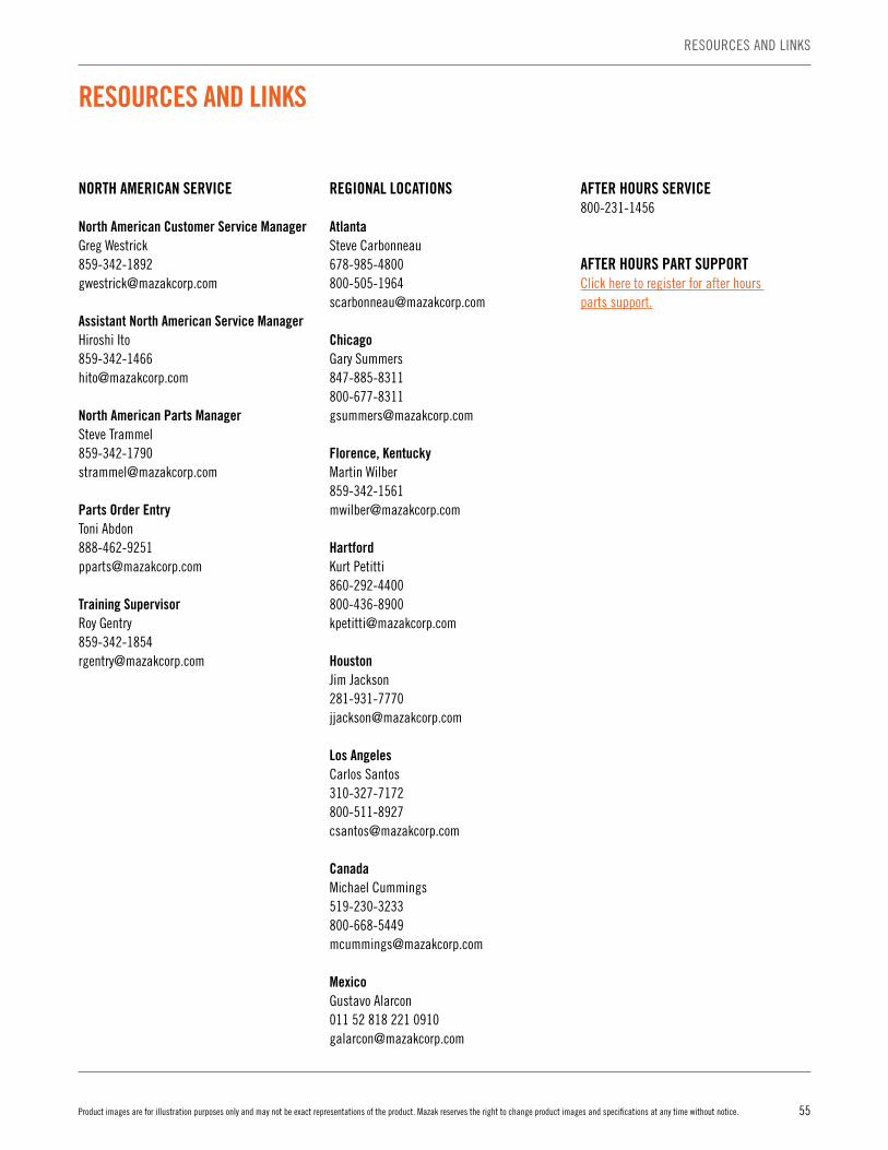
55Product images are for illustration purposes only and may not be exact representations of the product. Mazak reserves the right to change product images and specifications at any time without notice.
RESOURCES AND LINKS
RESOURCES AND LINKS
NORTH AMERICAN SERVICE
North American Customer Service ManagerGreg [email protected]
Assistant North American Service ManagerHiroshi [email protected]
North American Parts ManagerSteve [email protected]
Parts Order EntryToni [email protected]
Training SupervisorRoy [email protected]
REGIONAL LOCATIONS
AtlantaSteve [email protected]
ChicagoGary [email protected]
Florence, KentuckyMartin [email protected]
HartfordKurt [email protected]
HoustonJim [email protected]
Los AngelesCarlos [email protected]
CanadaMichael [email protected]
MexicoGustavo Alarcon011 52 818 221 [email protected]
AFTER HOURS SERVICE800-231-1456
AFTER HOURS PART SUPPORTClick here to register for after hours parts support.

MAZAK CORPORATION NORTH AMERICAN MANUFACTURING HEADQUARTERS8025 Production Drive, Florence, KY 41042 Tel: (859) 342-1700 Fax: (859) 342-1865
QT
U S
er
ies
www.MazakUSA.com
05_17_SER_QTU_B