qualification process of a gis 400 kv sf6 high voltage...
TRANSCRIPT

Qualification Process of a GIS 400 kV SF6 High Voltage Circuit Breaker Controlled Switching Solution
M. WALDRON
1
F. AÏT-ABDELMALEK2, A. FICHEUX
2, J-L. RAYON
2
1National Grid, United Kingdom
2Alstom Grid, Aix-les-Bains, France
SUMMARY
During the past decades and thanks to major improvement of intelligent electronic devices (IEDs) in
terms of reliability and costs, controlled switching solutions applied to high voltage circuit-breakers
have offered a relevant electronic alternative to more conventional methods, usually used to reduce the
switching transients and electrical constraints on the equipment. These controlled switching solutions
are now embedded into so-called point-on-wave (POW) controllers.
The success of controlled switching relies on two fundamental principles:
Identification of a target moment for connecting or disconnecting loads and sources
favourable to transient mitigation;
Reliable estimation of the duration of the operation for the device being controlled in order to
achieve effective switching operation at the predetermined target.
Thus, one of the challenges in controlled switching application lies in the prediction of the duration of
the operation, subject to the contingencies of the operating conditions.
This paper describes the detailed qualification process conducted for a controlled switching solution at
420 kV level together with the deployment on the field. A focus is made on 2 types of applications for
which National Grid in UK requires implementation of controlled switching solution:
Controlled de-energization of shunt reactor
Controlled closing of capacitive loads at zero voltage which is recognized as the most difficult
duty.
The first qualification process is related to the POW controller ability to operate accurately according
to a pre-set switching sequence under various ambient and severe EMV conditions particularly present
in GIS substation. The second one is oriented to the associated high-voltage circuit-breaker and its
parametric model is established according to the new IEC technical report TR 62271-302 [1] issued by
IEC and based heavily upon the work of Cigré WGA3.07 [2]. The third one consists of associating the
POW controller with the said circuit-breaker to operate in power laboratory live synchronized
switching operations. Finally, some site live start-up observation and performance evaluation are
provided as a conclusion of this process.
KEYWORDS
Controlled Switching Solution, Qualification Process, Circuit-Breaker Behaviour, Point-on-Wave
Controller, Asset Lifetime Extension
21, rue d’Artois, F-75008 PARIS A3-204 CIGRE 2014
http : //www.cigre.org

2
1. INTRODUCTION
The phenomena associated to switching capacitive loads and small inductive loads are well described
in the IEC technical report TR 62271-306 [3] and Cigré TB 050 [4]. Some resultant overvoltage can
be of significant magnitude and can require some form of limitation like use of surge arresters or point
on wave switching. In case of bank arrangement of cables or capacitors, additional phenomena need to
be considered (like inrush currents and associated high frequency transients).
Therefore, when switching capacitive or small inductive loads is of concern, specific requirements for
circuit-breakers intended to be used on such applications are specified by National Grid in their
technical specification related to circuit-breaker TS 3.2.1 [5].
Circuit-breakers intended for shunt reactor switching shall be capable of the addition of a controlled
opening facility to facilitate the minimization of re-ignition transients. Performance requirements
related to controlled switching facility for this application are the following:
- Operation of circuit-breaker applied to shunt reactor circuits shall not produce over voltages in
excess of 2 p.u. at the reactor terminals;
- Controlled opening facilities shall be demonstrated to be of sufficient accuracy to eliminate re-
ignitions.
Circuit-breakers intended for capacitive load switching shall be capable of the addition of a controlled
closing facility to facilitate minimization of closing transients when energizing either an earthed star
connected capacitor bank or parallel cable bank. Especially, it needs to eliminate strong inrush
currents that may occur during back-to-back random energization. Performance Requirements related
to controlled switching facility for this application are the following:
- The controlled switching system shall be capable of controlling the closing operations of the
circuit breaker such that the point of current initiation coincides with system voltage zero in
each phase with a tolerance of +/-1ms around the target voltage zero.
For both applications, the qualifications of the POW controller itself and the qualification of POW
controller associated with its circuit breaker are thus required.
According to National Grid requirement stated in [5], the circuit-breakers for intentionally non-
simultaneous pole operation shall be designed and tested in accordance with [1], which provides a
guideline to perform specific tests that allow characterization of the circuit-breaker intended to be
associated with a POW controller. They shall also be subjected to a series of live switching tests as
part of their final commissioning.
2. QUALIFICATION OF POW CONTROLLER WITH CIRCUIT BREAKER
2.1 POW Controller qualification
There is no specific IEC standard to design and qualify specifically the POW controller. However,
National Grid has issued two detailed specifications that are describing the tests to be performed to
qualify the controller as a stand-alone IED. References are TS3.24.54 [6] and TS 3.24.15 [7]
One of these tests is to check the accuracy of the POW controller to determine the optimum operation
moment and effectively issue command orders for various targeted switching angles.
The Point-on-Wave controller operates with high accuracy better than 0.1ms (<1.8° @50Hz).
Therefore the key issue is not the qualification of the controller itself, but the coupling of the POW
controller with its circuit-breaker.
2.2 POW Controller qualification with the circuit breaker
Controlled switching being considered for a switching application, the selection of the circuit-breaker
to perform its duty has to follow a specific process, out of IEC standard 62271-100 [8]. This is
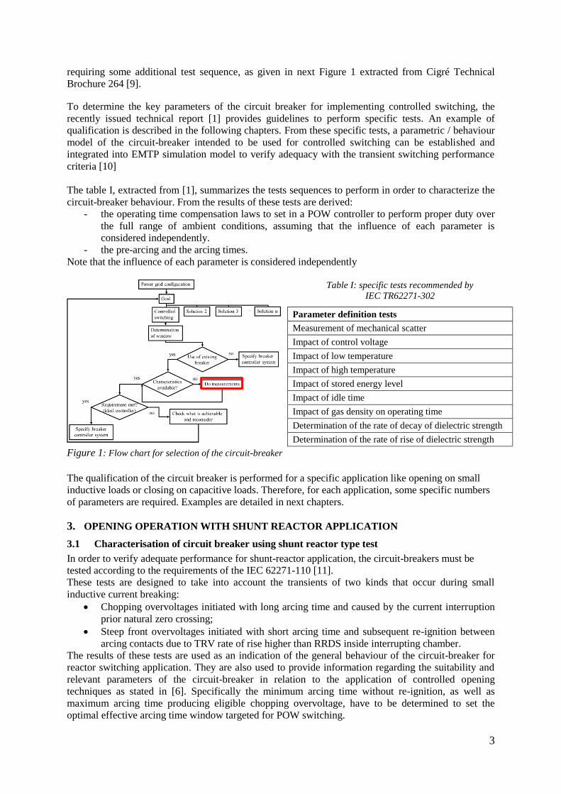
3
requiring some additional test sequence, as given in next Figure 1 extracted from Cigré Technical
Brochure 264 [9].
To determine the key parameters of the circuit breaker for implementing controlled switching, the
recently issued technical report [1] provides guidelines to perform specific tests. An example of
qualification is described in the following chapters. From these specific tests, a parametric / behaviour
model of the circuit-breaker intended to be used for controlled switching can be established and
integrated into EMTP simulation model to verify adequacy with the transient switching performance
criteria [10]
The table I, extracted from [1], summarizes the tests sequences to perform in order to characterize the
circuit-breaker behaviour. From the results of these tests are derived:
- the operating time compensation laws to set in a POW controller to perform proper duty over
the full range of ambient conditions, assuming that the influence of each parameter is
considered independently.
- the pre-arcing and the arcing times.
Note that the influence of each parameter is considered independently
Table I: specific tests recommended by
IEC TR62271-302
Parameter definition tests
Measurement of mechanical scatter
Impact of control voltage
Impact of low temperature
Impact of high temperature
Impact of stored energy level
Impact of idle time
Impact of gas density on operating time
Determination of the rate of decay of dielectric strength
Determination of the rate of rise of dielectric strength
Figure 1: Flow chart for selection of the circuit-breaker
The qualification of the circuit breaker is performed for a specific application like opening on small
inductive loads or closing on capacitive loads. Therefore, for each application, some specific numbers
of parameters are required. Examples are detailed in next chapters.
3. OPENING OPERATION WITH SHUNT REACTOR APPLICATION
3.1 Characterisation of circuit breaker using shunt reactor type test
In order to verify adequate performance for shunt-reactor application, the circuit-breakers must be
tested according to the requirements of the IEC 62271-110 [11].
These tests are designed to take into account the transients of two kinds that occur during small
inductive current breaking:
Chopping overvoltages initiated with long arcing time and caused by the current interruption
prior natural zero crossing;
Steep front overvoltages initiated with short arcing time and subsequent re-ignition between
arcing contacts due to TRV rate of rise higher than RRDS inside interrupting chamber.
The results of these tests are used as an indication of the general behaviour of the circuit-breaker for
reactor switching application. They are also used to provide information regarding the suitability and
relevant parameters of the circuit-breaker in relation to the application of controlled opening
techniques as stated in [6]. Specifically the minimum arcing time without re-ignition, as well as
maximum arcing time producing eligible chopping overvoltage, have to be determined to set the
optimal effective arcing time window targeted for POW switching.
4
3.2 Characterisation of circuit breaker for shunt-reactor controlled opening operation
3.2.1 Determination of the arcing time window
As summarized in Figure 4
Minimum arcing time without re-ignition is derived from the test sequences performed at both
nominal condition and lock-out condition
Maximum arcing time is determined in line with insulation coordination study to limit the
suppression peak overvoltage at shunt-reactor terminals.
Therefore the arcing contact separation window to consider for POW controller setting
Figure 2 : Short arcing time re-ignition Figure 3 : CB during small inductive current
interruption test
Figure 4 : 400kV CB arcing time Figure 5 : 400kV CB opening time distribution
3.2.2 Determination of the opening time standard deviation
Circuit-breaker opening time scatter and standard deviation are determined by a set of 100 consecutive
opening operations at control voltage rated value (100%) and control voltage minimum value (70%)
and under stable conditions of all other influencing parameters.
During this sequence, operating times of arcing contact and signalling device used by POW controller
for CB timing measurement are measured.
It appears from the measurements performed that the opening time distribution behaves as a normal
(Gaussian) distribution with a standard deviation of less than 0.2 ms / 3.6°@50Hz.
Note: determination of the opening time compensation laws
During each test sequence, all other ambient influencing factors remain under stable conditions.
Compensation laws to program the controller are derived from these measurements, a mean value
from 30 operations being considered for each influencing parameter level.
0.8
0.9
1
1.1
1.2
1.3
1.4
1.5
1.6
1.7
0 30 60 90 120 150 180 210 240
Sup
pre
ssio
n p
eak
volt
age
(p.u
.)
Arcing time (°)
Re-ignition & Suppression peak voltage vs. arcing time
Ir = 270A (Pnom) Ir = 113A (Pnom) Ir = 113A (Pmin)
Re-ignition
0
5
10
15
20
25
30
35
40
-20 -15 -10 -5 0 5 10 15 20
Freq
uen
cy [
%]
Opening time deviation [° - Base 50Hz]
Opening time distribution
Uc=100% Uc=85%
Unwanted
re-ignition window
Unwanted
Overvoltage window Targeted window for
Contact separation

5
3.3 Test combination of POWC with CB
The determination of the minimum arcing time without re-ignition and maximum overvoltage allowed
at the reactor terminal allow setting the optimum window to target the arcing contact separation.
A test in laboratory of CB with associated POW controller to perform controlled opening operation is
not recommended by IEC TR62271-302. Indeed it can be skipped with regards to opening time narrow
scatter and low standard deviation that guarantee contact separation within a sufficiently wide
demonstrated window.
3.4 Field live test for commissioning
Following satisfactory laboratory acceptance tests and successful field commissioning tests during
normal conditions, the latest generation of POW controller was put into service in 2012 for one of the
National Grid project. The application was for controlled opening of shunt reactor in an outdoor GIS
application. The integration of this reactor onto the network was part of the London reinforcement
project and was put into service to meet the target of the 2012 London Olympics. It has now recorded
more than one year field operational experience, featuring successful reactor opening operations
within the targeted arcing window.
Typical results for shunt-reactor opening are shown below.
Figure 6 : 400kV outdoor shunt-
reactor CB
Figure 7 : Shunt-reactor current interruption record
4. CAPACITIVE LOAD CLOSING OPERATION
4.1 Phenomena associated to capacitive load switching with zero voltage making
The objective of controlled closing of a HVAC circuit-breaker is to synchronize the instant of current
flow initiation in the circuit with a targeted switching angle based on a reference synchronizing signal.
Practically it consists of closing at zero voltage across the arcing contacts (used to minimize the
phenomena of pre-strike) in order to get the current flow initiation while the arcing contacts are
closing.
Zero-voltage making is recognized as the most difficult duty since the derivative (d) of applied voltage
at circuit-breaker terminals is maximum when it is getting towards zero value. Refer to formula (1).
( ) p.u/rad (1)
4.1.1 Rate of decay of dielectric strength (RDDS)
Thus, the first principle for a circuit-breaker dedicated to perform controlled closing operations on
capacitive loads with zero voltage objective is to have a sufficient RDDS slope, to prevent from
adverse pre-strike phenomena. Typically, the corresponding slope must be higher than the voltage
derivative at its zero crossing. The closing speed of the circuit-breaker combined with SF6 dielectric
withstand are fundamental to guarantee succesful controlled energizing without prestrike. Figure 8
shows the example of a closing operation with a poor RDDS slope. Pre-strike is happening while the
arcing contacts are still significantly separated, and hence when there is a significant voltage across the
closing contacts. On Figure 10, the RDDS slope is higher, circuit is established when the arcing
contacts are just getting in touch and pre-strike is therefore eliminated in case of ideal closing at zero
voltage.
-0.5
-0.25
0
0.25
0.5
0.75
1
1.25
1.5
-300
-250
-200
-150
-100
-50
0
50
100
340 345 350 355 360 365 370 375 380
Vo
ltag
e [V
]
Time [ms]
Shunt reactor current interruption Usource_L1 Usource_L2 Usource_L3I_L1 I_L2 I_L3
Cu
rren
t [A
]
Arcing contacts Separation
Current Interruption

6
Figure 8 : pre-strike in circuit-breaker with poor
RDDS
Figure 9 : circuit-breaker zero-voltage closing
characteristics Figure 10 : pre-strike eliminated in circuit-
breaker with high RDDS
4.1.2 Closing time standard deviation
High slope RDDS is nevertheless not substantial enough to perform proper operation. Indeed, large
closing time scatter may statistically lead to significant prestrike voltages. The second principle for
circuit-breaker performance is a low closing time scatter. It should be low enough to allow a narrow
making window, as shown on Figure 11. It can be clearly seen in this figure that, by targeting the
voltage zero, the pre-strike voltage at the early & late limits of the RDDS envelope differ significantly.
4.1.3 Optimized controlled closing
From the previous statement and figures, it is clearly understandable that optimal switching
performance cannot be reached without any additional contribution coming from the Point-on-Wave
controller intended to synchronize the circuit-breaker. It has to integrate the switching device
characteristics, the RDDS slope and the closing time standard deviation, and delay the target time for
closing slightly from voltage zero in order to optimize the control of the maximum pre-strike voltage,
thus equilibrating the risk of pre-strike (refer to Figure 12). Shifting delay is defined by formula (2)
with being the closing time standard deviation.
( )
(2)
Figure 11 : impact of CB closing time scatter on pre-
strike characteristics Figure 12 : optimized controlled closing operation
4.2 Characterisation of circuit-breaker for closing operation
4.2.1 Determination of the rate of decay of dielectric strength (RDDS)
The circuit-breaker is tested in high voltage test laboratory with rated operating conditions and
following pre-conditioning at lock-out operating conditions. Test voltage applied is twice the rated
voltage. The preferred methodology recommended by [1] to determine the RDDS is the “around the
clock method” consisting in delaying by 15° the closing order from one operation to the consecutive
one.
0
0.1
0.2
0.3
0.4
0.5
0.6
0.7
0.8
0.9
1
-90 -80 -70 -60 -50 -40 -30 -20 -10 0 10 20 30 40 50 60 70 80 90
Vo
ltag
e (p
.u.)
Angle [°]
Controlled closing - Zero voltage making
Voltage across CB CB RDDS > (d) CB RDDS < (d)
0
0.1
0.2
0.3
0.4
0.5
0.6
0.7
0.8
0.9
1
-90 -80 -70 -60 -50 -40 -30 -20 -10 0 10 20 30 40 50 60 70 80 90
Vo
ltag
e [
p.u
.]
Angle [°]
Controlled closing - Zero voltage making
Voltage across CB CB RDDS > (d)
0
0.1
0.2
0.3
0.4
0.5
0.6
0.7
0.8
0.9
1
-90 -80 -70 -60 -50 -40 -30 -20 -10 0 10 20 30 40 50 60 70 80 90
Vo
ltag
e (
p.u
.)
Angle (°)
Controlled closing - Zero voltage making
Voltage across CB CB RDDS > (d) dispersion
7
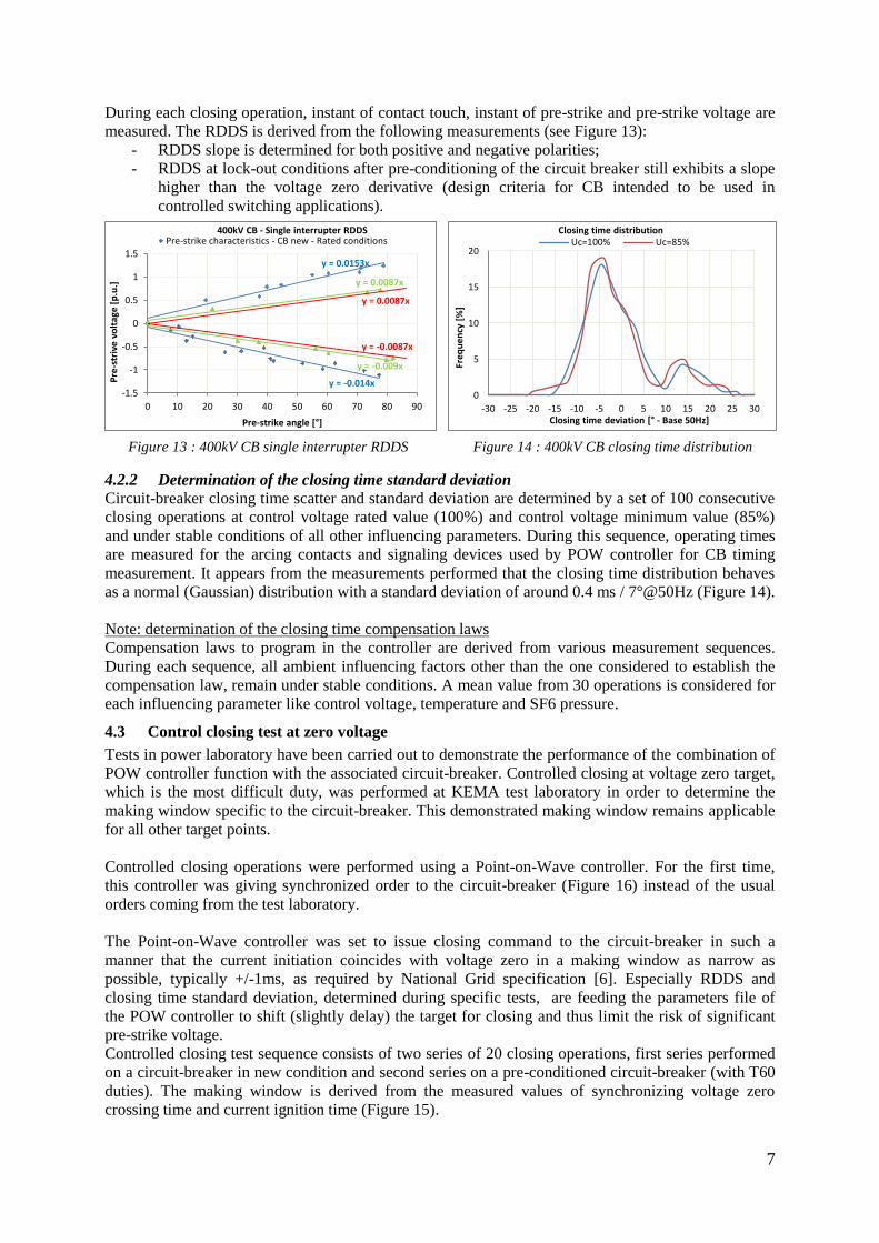
During each closing operation, instant of contact touch, instant of pre-strike and pre-strike voltage are
measured. The RDDS is derived from the following measurements (see Figure 13):
- RDDS slope is determined for both positive and negative polarities;
- RDDS at lock-out conditions after pre-conditioning of the circuit breaker still exhibits a slope
higher than the voltage zero derivative (design criteria for CB intended to be used in
controlled switching applications).
Figure 13 : 400kV CB single interrupter RDDS Figure 14 : 400kV CB closing time distribution
4.2.2 Determination of the closing time standard deviation
Circuit-breaker closing time scatter and standard deviation are determined by a set of 100 consecutive
closing operations at control voltage rated value (100%) and control voltage minimum value (85%)
and under stable conditions of all other influencing parameters. During this sequence, operating times
are measured for the arcing contacts and signaling devices used by POW controller for CB timing
measurement. It appears from the measurements performed that the closing time distribution behaves
as a normal (Gaussian) distribution with a standard deviation of around 0.4 ms / 7°@50Hz (Figure 14).
Note: determination of the closing time compensation laws
Compensation laws to program in the controller are derived from various measurement sequences.
During each sequence, all ambient influencing factors other than the one considered to establish the
compensation law, remain under stable conditions. A mean value from 30 operations is considered for
each influencing parameter like control voltage, temperature and SF6 pressure.
4.3 Control closing test at zero voltage
Tests in power laboratory have been carried out to demonstrate the performance of the combination of
POW controller function with the associated circuit-breaker. Controlled closing at voltage zero target,
which is the most difficult duty, was performed at KEMA test laboratory in order to determine the
making window specific to the circuit-breaker. This demonstrated making window remains applicable
for all other target points.
Controlled closing operations were performed using a Point-on-Wave controller. For the first time,
this controller was giving synchronized order to the circuit-breaker (Figure 16) instead of the usual
orders coming from the test laboratory.
The Point-on-Wave controller was set to issue closing command to the circuit-breaker in such a
manner that the current initiation coincides with voltage zero in a making window as narrow as
possible, typically +/-1ms, as required by National Grid specification [6]. Especially RDDS and
closing time standard deviation, determined during specific tests, are feeding the parameters file of
the POW controller to shift (slightly delay) the target for closing and thus limit the risk of significant
pre-strike voltage.
Controlled closing test sequence consists of two series of 20 closing operations, first series performed
on a circuit-breaker in new condition and second series on a pre-conditioned circuit-breaker (with T60
duties). The making window is derived from the measured values of synchronizing voltage zero
crossing time and current ignition time (Figure 15).
y = -0.014x
y = 0.0153x
y = -0.009x
y = 0.0087x
y = 0.0087x
y = -0.0087x
-1.5
-1
-0.5
0
0.5
1
1.5
0 10 20 30 40 50 60 70 80 90
Pre
-str
ive
volt
age
[p.u
.]
Pre-strike angle [°]
400kV CB - Single interrupter RDDS Pre-strike characteristics - CB new - Rated conditions
0
5
10
15
20
-30 -25 -20 -15 -10 -5 0 5 10 15 20 25 30
Freq
uen
cy [
%]
Closing time deviation [° - Base 50Hz]
Closing time distribution Uc=100% Uc=85%
8
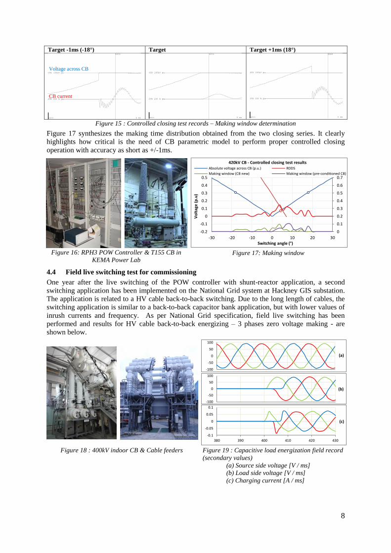
Target -1ms (-18°) Target Target +1ms (18°)
Figure 15 : Controlled closing test records – Making window determination
Figure 17 synthesizes the making time distribution obtained from the two closing series. It clearly
highlights how critical is the need of CB parametric model to perform proper controlled closing
operation with accuracy as short as +/-1ms.
Figure 16: RPH3 POW Controller & T155 CB in
KEMA Power Lab Figure 17: Making window
4.4 Field live switching test for commissioning
One year after the live switching of the POW controller with shunt-reactor application, a second
switching application has been implemented on the National Grid system at Hackney GIS substation.
The application is related to a HV cable back-to-back switching. Due to the long length of cables, the
switching application is similar to a back-to-back capacitor bank application, but with lower values of
inrush currents and frequency. As per National Grid specification, field live switching has been
performed and results for HV cable back-to-back energizing – 3 phases zero voltage making - are
shown below.
Figure 18 : 400kV indoor CB & Cable feeders Figure 19 : Capacitive load energization field record
(secondary values)
(a) Source side voltage [V / ms]
(b) Load side voltage [V / ms]
(c) Charging current [A / ms]
ITO 200 A pu
UTO 100kV pu
4014
unit 5 ms
ITO 200 A pu
UTO 100kV pu
4015
unit 5 ms
ITO 200 A pu
UTO 100kV pu
4026
unit 5 ms
0
0.1
0.2
0.3
0.4
0.5
0.6
0.7
-0.2
-0.1
0
0.1
0.2
0.3
0.4
0.5
-30 -20 -10 0 10 20 30
Vo
ltag
e (p
.u)
Switching angle (°)
420kV CB - Controlled closing test results Absolute voltage across CB (p.u.) RDDS
Making window (CB new) Making window (pre-conditioned CB)
-100
-50
0
50
100
(a)
-100
-50
0
50
100
(b)
-0.1
-0.05
0
0.05
0.1
380 390 400 410 420 430
(c)
Voltage across CB
CB current

9
5. CONCLUSION
POW controllers have positive impact on switching duties of circuit-breaker for various applications
where transients mitigation is required. Qualification of the circuit-breaker intended to perform
controlled switching operations together with the associated controller is a key issue.
The IEC technical report IEC TR 62271-302 gives good guidance to implement specific tests.
Field test are also needed to prove correct procedure and implementation.
First cases that followed this qualification process and implemented in UK prove that these
requirements are well defined to achieve properly the start-up of the complete solution “POW
controller along with circuit-breaker”.
In perspective, newly created Cigré WGA3.35 will provide “Guidelines and Best Practices for the
Commissioning of Controlled Switching Projects” to lead utilities to successful field operation.
BIBLIOGRAPHY
[1] IEC/TR 62271-302 - High-voltage switchgear and controlgear
Part 302: Alternating current circuit-breakers with intentionally non-simultaneous pole
operation; Edition 1, 2010-06
[2] CIGRE WG 13.07, “Controlled Switching of HVAC Circuit-breakers: Guide for Application”;
Part 1: Electra, No. 183, April 1999. Part 2: Electra, No. 185, August 1999.
[3] IEC/TR 62271-306 - High-voltage switchgear and controlgear
Part 306: Guide to IEC 62271-100, IEC 62271-1 and other IEC standards related to alternating
current circuit-breakers; Edition 1, 2012-12
[4] Cigré TB 050 - Interruption of small inductive currents; WG 13.02; 1995
[5] TS 3.02.01 - National Grid - Internal and Contract Specific Technical Specification - Circuit-
breakers; Issue 4 – July 2011
[6] TS 3.24.54 - National Grid - Technical Specification – Circuit-breaker Point-on-Wave
Switching Control; Issue 1 – March 2001
[7] TS 3.24.15 - National Grid - Technical Specification – Environmental and Test Requirements
for Electronic Equipment; Issue 1 – December 2000
[8] IEC 62271-100 - High-voltage switchgear and controlgear
Part 100: Alternating current circuit-breakers; Edition 2.1, 2012-09
[9] Cigré TB 264 - Controlled Switching of HVAC CBs - Planning Specification Testing; WG
A3.07; 2004
[10] Cigré TB 135 - State of the art of circuit-breaker modeling; WG 13.01; 1998
[11] IEC 62271-110 - High-voltage switchgear and controlgear
Part 110: Inductive load switching; Edition 3.0, 2012-09