quality assurance dacument - practical answerspracticalanswers.lk/pdfs/qa1.pdfprocess guideline...
TRANSCRIPT
Process guideline
Contact: Resource Desk at
Practical Action
No 5, Lionel Edirisinghe Mw, Colombo 5, Sri Lanka.
T +94 (11) 2829412 F +94 (11) 2856188
W www.practicalaction.org www.janathakshan.net E [email protected]
Quality assurance guidelines for building construction Introduction
Quality assurance throughout the process of construction of any building is important for the sustainability of the building. Houses in disaster-prone areas in particular should be able to withstand the rigours of natural disasters such as heavy rains, high speed winds, floods and earthquakes. This section sets out the guidelines to be followed closely to ensure the quality of houses constructed in disaster-prone areas and has been developed for use by;
Implementers of housing construction projects, house owners, site supervisors, masons, & carpenters
Technical Officers and Engineers.
The following information provides general guidelines for quality standards when building one storey or two storey houses constructed on stable soil – not multi-storeyed buildings that are greater than two storeys. Soil conditions will vary at sites where buildings will be constructed, therefore this document is limited to providing basic information on quality standards for foundations that are suited to relatively stable soil. Bearing capacities of other soils (e.g. sand, soft silt, clay and recently filled land etc.) would require detailed specifications provided by a qualified structural engineer. Quality standards for foundations in other soil types – listed above – are not included in this document.
This document is intended to assist building masons, workers in concrete construction and carpenters in maintaining reliable standards in carrying out their respective work on a construction site.
Standards related to site organisation and building services
such as plumbing, sanitation and electrical work are not included in this document. Technical officers and civil engineers too would be assisted by the checklists in this document as these would facilitate their work in ensuring that quality is maintained throughout the construction process. The information in this document, though essentially technical, has been prepared to serve as a guide to implementers of housing projects as well as eventual owners of the houses who would be concerned about the quality of the buildings that are to be occupied.
The guidelines focus on the:
Quality assurance in the choice of basic materials.
Quality assurance in the use of materials and construction methods.
The choice and use of basic building materials
High quality materials will not only provide structural stability but also ensure an attractive appearance.
When unsuitable materials are supplied to the site, they must be rejected.
Before choosing suppliers it is important to establish the reliability of the suppliers and the quality of the materials they supply.
Process guideline
Practical Action Quality assurance guidelines for building construction Process Guideline 2
Strict checks must be carried out consistently on the quality of each batch of building materials delivered to the building site.
Due care must be paid to ensure proper storage and handling of building materials.
Fired clay brick
Have you tested chosen samples of each batch delivered to site by:
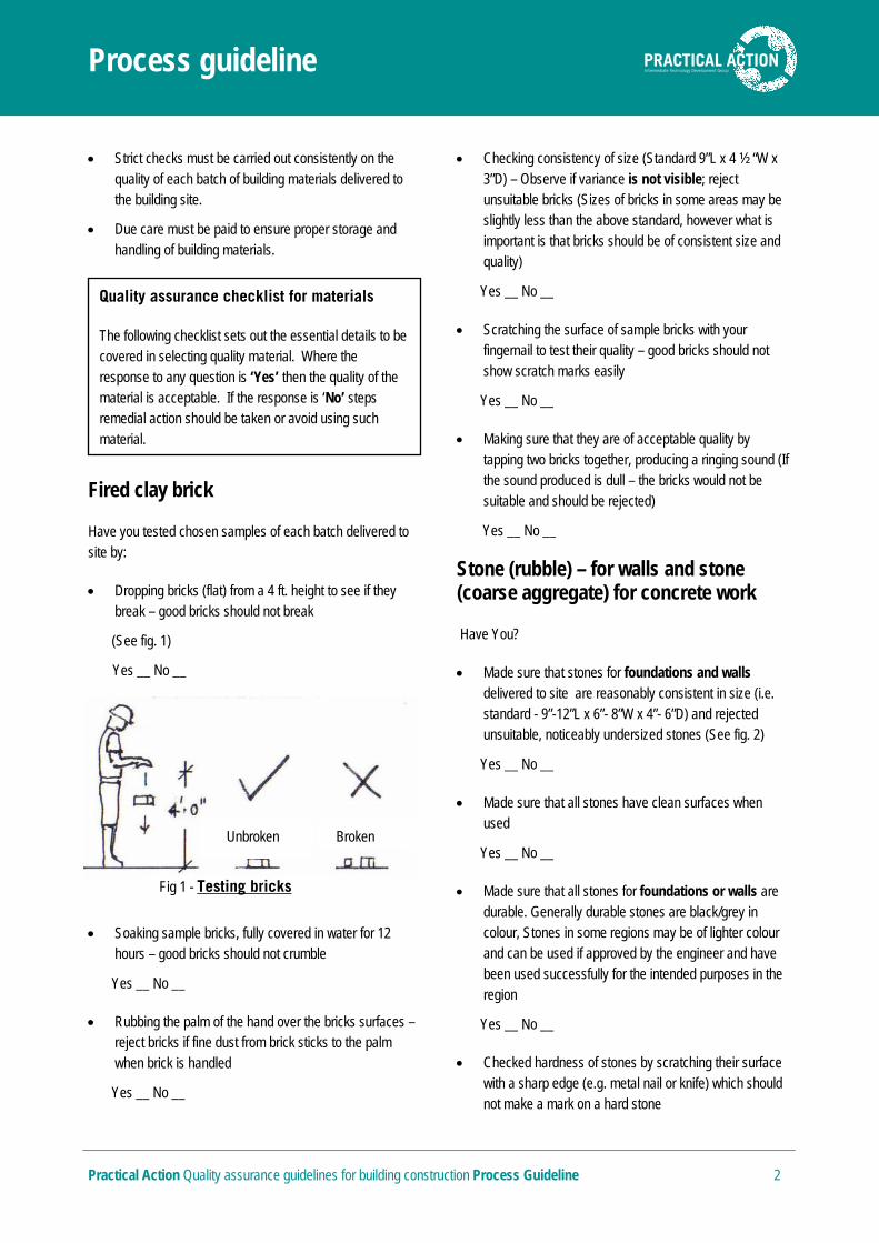
Dropping bricks (flat) from a 4 ft. height to see if they break – good bricks should not break
(See fig. 1)
Yes __ No __
Soaking sample bricks, fully covered in water for 12 hours – good bricks should not crumble
Yes __ No __
Rubbing the palm of the hand over the bricks surfaces – reject bricks if fine dust from brick sticks to the palm when brick is handled
Yes __ No __
Checking consistency of size (Standard 9”L x 4 ½ “W x 3”D) – Observe if variance is not visible; reject unsuitable bricks (Sizes of bricks in some areas may be slightly less than the above standard, however what is important is that bricks should be of consistent size and quality)
Yes __ No __
Scratching the surface of sample bricks with your fingernail to test their quality – good bricks should not show scratch marks easily
Yes __ No __
Making sure that they are of acceptable quality by tapping two bricks together, producing a ringing sound (If the sound produced is dull – the bricks would not be suitable and should be rejected)
Yes __ No __
Stone (rubble) – for walls and stone (coarse aggregate) for concrete work
Have You?
Made sure that stones for foundations and walls delivered to site are reasonably consistent in size (i.e. standard - 9”-12”L x 6”- 8”W x 4”- 6”D) and rejected unsuitable, noticeably undersized stones (See fig. 2)
Yes __ No __
Made sure that all stones have clean surfaces when used
Yes __ No __
Made sure that all stones for foundations or walls are durable. Generally durable stones are black/grey in colour, Stones in some regions may be of lighter colour and can be used if approved by the engineer and have been used successfully for the intended purposes in the region
Yes __ No __
Checked hardness of stones by scratching their surface with a sharp edge (e.g. metal nail or knife) which should not make a mark on a hard stone
Quality assurance checklist for materials
The following checklist sets out the essential details to be covered in selecting quality material. Where the response to any question is ‘Yes’ then the quality of the material is acceptable. If the response is ‘No’ steps remedial action should be taken or avoid using such material.
Fig 1 - Testing bricks
Unbroken Broken

Process guideline
Practical Action Quality assurance guidelines for building construction Process Guideline 3
Yes __ No __
Made sure that stones for coarse aggregate (i.e. metal for use in concrete) are of reasonably consistent sizes as specified, are angular; not rounded (Standard sizes of metal aggregate – 1/2”, 3/4” & 3/16” to 1/4”)
Yes __ No __
Made sure that thin, flat or flaky aggregate pieces are not used
Yes __ No __
Note:
Pieces of stone smaller than the sizes given above can be used as wedges when filling small voids between larger stones with mortar. However, all effort must be made to bond all main stones together with mortar, and minimize use of small stones as infill material.
Cement
Have you?
Tested the freshness of cement by making sure there are no large lumps of set cement that are not soft enough to be powdered when pressed with the fingers (When fresh cement is rubbed between fingers it should feel like smooth powder like flour. Grittiness may indicate reduced quality. Such cement should not be used)
Yes __ No __
Stored cement on a raised platform, in a dry location to make sure there is no loss of its strength, and ensured
air-tightness of packing and rejected cement packs that are unsatisfactory
Yes __ No __
Ensured that cement is used quickly and not stored for excessive periods of time and rejected unsuitable cement – (cement, after 3 months storage, loses its strength by 20%)
Yes __ No __
Sand – (Fine aggregate)
Have you?
Checked that the sand supplied for construction is river sand that is free of deleterious materials such as silt, clay, mica etc.
Yes __ No __
Made sure that sea sand is not used.* (To recognize sea sand – observe if there are particles of marine shells in the sand. Also place some sand in a cup of water and taste the solution for traces of salt)
Yes __ No __
Checked whether the sand is clean, sharp and angular (not round)
Yes __ No __
Sand is also used as the fine aggregate component in concrete and should be relatively free of salt that has a corrosive effect on reinforcement steel. For this reason it is important that sea sand should not be used for construction.
Sand should be clean, sharp, angular (gritty to the touch), hard and durable; free from clay silt and organic material. (Generally 4 to 6 % of clay and silt are permitted). Rub a sample of sand between damp hands and if only a slight stain remains after the sand is thrown – it is acceptable. If hands become noticeably dirty due to presence of excessive amount of clay, the sand should not be used.
Fig 2 - Average stone size

Process guideline
Practical Action Quality assurance guidelines for building construction Process Guideline 4
Crushed stone (Fine aggregate – If proposed for use as an alternative to sand)
Note:
Crushed stone (quarry dust), if used instead of sand, should be approved by the structural engineer responsible for structural design. Very fine quarry dust is not a suitable alternative for sand because it reduces the strength of the concrete and requires more cement to be used.
Have you?
Checked the suitability of quarry dust by using a bottle test to compare The size of particles with that of sand (See fig. 3)
Yes __ No __
(This is done by placing a quantity of sand in a bottle of water and shaking it; allowing the sand to settle. Then, placing an equal volume of quarry dust in a similar sized bottle of water and shaking it, allowing the sand to settle. Thereafter, compare the appearance of the particles with that of the sand. If it appears that the particles of quarry dust are mostly finer than the sand grains; the quarry dust should not be used).
Water
Have You?
Made sure that water to be used for construction is potable – clean and free from noticeable salt content
that will have a corrosive effect on the reinforcements in RCC work (unsuitable water must not be used)
Yes __ No __
Made sure that the water to be used is free of silt, oils, soaps, detergents and organic impurities
Yes __ No __
Made sure that sufficient quantity of water is available on site when carrying out proposed concreting or other work
Yes __ No __
Made sure that the incoming water supply pipe line is protected from accidental damage, due to movement of vehicles on site
Yes __ No __
Steel reinforcements
Have You?
Checked the diameter of reinforcement rods supplied, to make sure that they are exactly the sizes specified by the engineer to be used
Yes __ No __
Checked that all reinforcement rods are free from loose residue metal particles on surface, or rust, oil and grease, immediately before placing the concrete in order to enable proper bonding between steel and concrete. (A thin discolouration or light rust which adheres firmly to the bars is permitted.)
Yes __ No __
Stored the bars off the ground and effectively covered them to protect them from rain and to prevent rusting
Yes __ No __
Note:
When steel rods are to be stored for some time they can be given a cement wash (a solution of cement and water) to prevent promotion of rusting. Loose rust can be cleaned with a wire brush or hession cloth (gunny). Oil, grease and paint can
Fig 3 - Testing fine aggregate
Water
Grainy sand
Sand Quarry dust
Water
Dust mostly
Process guideline
Practical Action Quality assurance guidelines for building construction Process Guideline 5
be easily removed by passing bars through fire or with the help of a blow lamp.
All reinforcement steel to be Tor, except 6mm mild steel for stirrups
Timber
Have You?
Checked that the quality of the timber to be used is good. Timber should be free of dead knots (which can be identified if the knots can be prised out with a blunt instrument), as well as free of cracks, and sapwood (identified by distinct lightness of colour), and not warped (testing of straightness/flatness done by placing the timber member on a flat surface)
Yes __ No __
Rejected all unsuitable timber as described above
Yes __ No __
Checked the sizes and type/s of timber to make sure if these conform to the given specifications for timber to be used for the building
Yes __ No __
Made sure that pre-treated timber is obtained from reliable suppliers
Yes __ No __
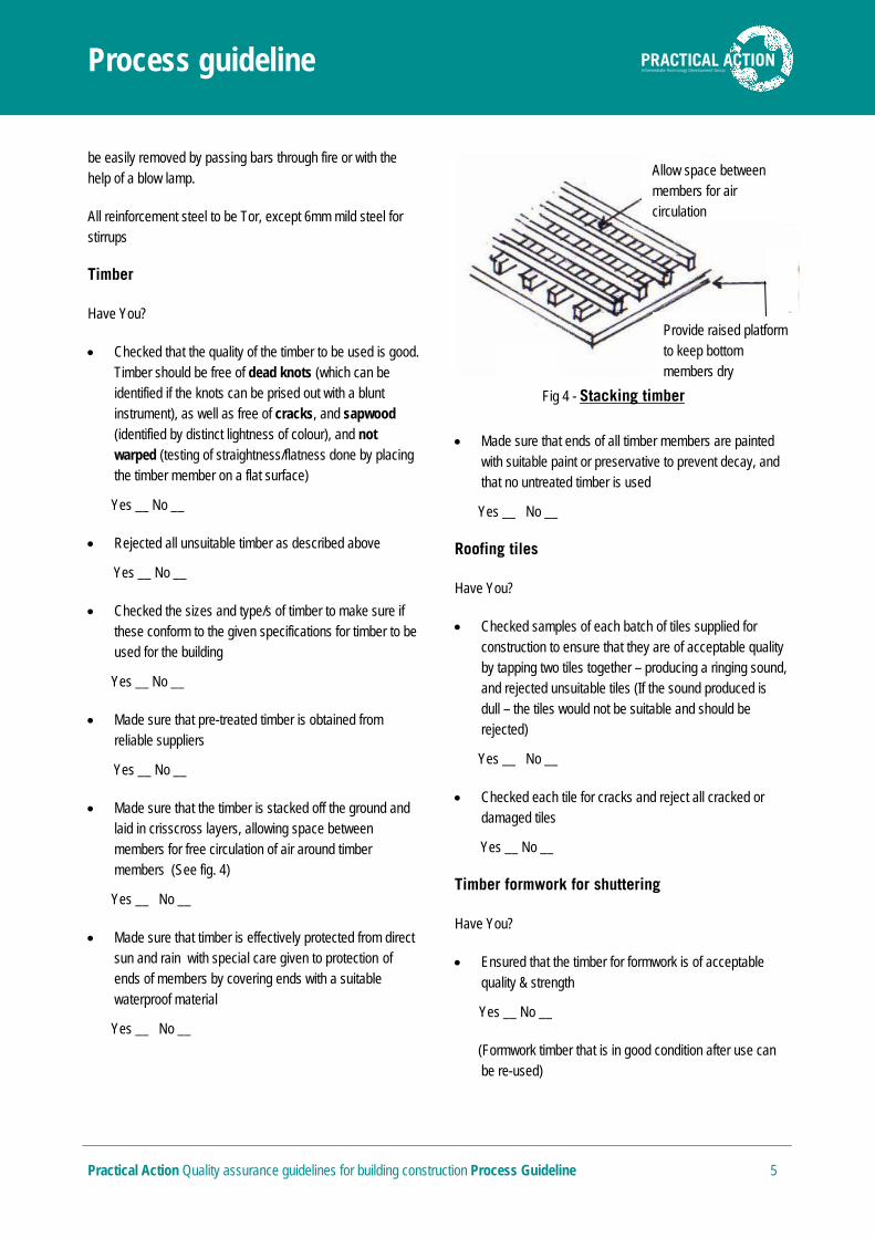
Made sure that the timber is stacked off the ground and laid in crisscross layers, allowing space between members for free circulation of air around timber members (See fig. 4)
Yes __ No __
Made sure that timber is effectively protected from direct sun and rain with special care given to protection of ends of members by covering ends with a suitable waterproof material
Yes __ No __
Made sure that ends of all timber members are painted with suitable paint or preservative to prevent decay, and that no untreated timber is used
Yes __ No __
Roofing tiles
Have You?
Checked samples of each batch of tiles supplied for construction to ensure that they are of acceptable quality by tapping two tiles together – producing a ringing sound, and rejected unsuitable tiles (If the sound produced is dull – the tiles would not be suitable and should be rejected)
Yes __ No __
Checked each tile for cracks and reject all cracked or damaged tiles
Yes __ No __
Timber formwork for shuttering
Have You?
Ensured that the timber for formwork is of acceptable quality & strength
Yes __ No __
(Formwork timber that is in good condition after use can be re-used)
Fig 4 - Stacking timber
Allow space between members for air circulation
Provide raised platform to keep bottom members dry

Process guideline
Practical Action Quality assurance guidelines for building construction Process Guideline 6
Made sure that all timber or plywood shuttering is well cleaned and free of dirt, wood shavings, nails etc.
Yes __ No __
Made sure that all shuttering panels have straight edges that can be closely fitted so as to prevent water leakage during placing of concrete
Yes __ No __
Sizes of timber for formwork (General guidelines)
Members Sizes (in inches)
Flat sheets for slab bottoms, column & beam sides
1” to 2” thick
Beam bottoms
2” thick
Vertical posts 3” x 4” to 6” x 6”
Joists & ledgers supporting sheeting of slabs
2” x 3” to 4” x 8”
Studs and supports for supporting vertical wall sheeting
2” x 4” to 6” x 6”
Column yokes – horizontal cross pieces for supporting vertical sheeting
2” x 4” to 4” x 4”
Note:
The sizes of formwork stated above are applicable for spans up to 16’ and height up to 13’ roughly, in slabs; thickness of shuttering should be at least one-third the depth of the slab.
Scaffolding (props) for formwork
Have You?
Made sure that all tie bolts and clamps etc. that are essential accessories of a scaffolding kit are used as per manufacturer’s specifications
Yes __ No __
Made sure that top and bottom plates of vertical scaffolding are at right angles to the vertical members and are not deformed
Yes __ No __
Made sure that sizes (diameters and heights) of bamboo props (if used) are consistent and avoided use of mixed sizes (See fig. 5)
Yes __ No __
Quality assurance in the use of materials and construction methods
Stone work (in foundations)
Have you?
Pad
Fig 5 - Bamboo props
Pad
Process guideline
Practical Action Quality assurance guidelines for building construction Process Guideline 7
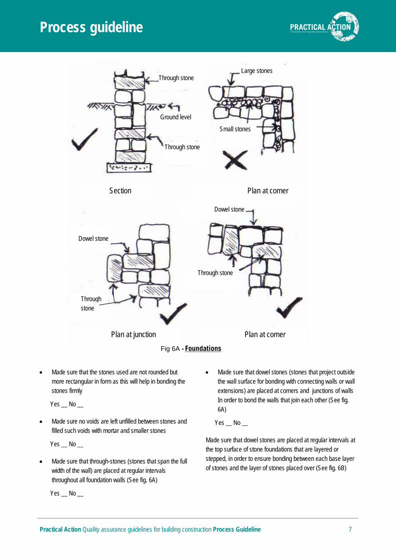
Made sure that the stones used are not rounded but more rectangular in form as this will help in bonding the stones firmly
Yes __ No __
Made sure no voids are left unfilled between stones and filled such voids with mortar and smaller stones
Yes __ No __
Made sure that through-stones (stones that span the full width of the wall) are placed at regular intervals throughout all foundation walls (See fig. 6A)
Yes __ No __
Made sure that dowel stones (stones that project outside the wall surface for bonding with connecting walls or wall extensions) are placed at corners and junctions of walls In order to bond the walls that join each other (See fig. 6A)
Yes __ No __
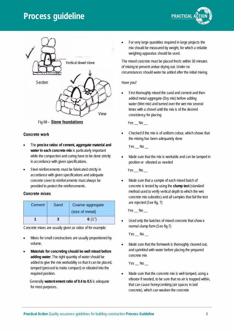
Made sure that dowel stones are placed at regular intervals at the top surface of stone foundations that are layered or stepped, in order to ensure bonding between each base layer of stones and the layer of stones placed over (See fig. 6B)
Fig 6A - Foundations
Through stone
Ground level
Through stone
Small stones
Large stones
Plan at junction Plan at corner
Section Plan at corner
Through stone
Dowel stone
Through stone
Dowel stone
Process guideline
Practical Action Quality assurance guidelines for building construction Process Guideline 8
Concrete work
The precise ratios of cement, aggregate material and water in each concrete mix is particularly important while the compaction and curing have to be done strictly in accordance with given specifications.
Steel reinforcements must be fabricated strictly in accordance with given specifications and adequate concrete cover to reinforcements must always be provided to protect the reinforcements.
Concrete mixes
Cement Sand Coarse aggregate
(size of metal)
1 3 6 (1”)
Concrete mixes are usually given as ratios of for example:
Mixes for small constructions are usually proportioned by volume.
Materials for concreting should be well mixed before adding water. The right quantity of water should be added to give the mix workability so that it can be placed, tamped (pressed to make compact) or vibrated into the required position.
Generally water/cement ratio of 0.4 to 0.5 is adequate for most purposes.
For very large quantities required in large projects the mix should be measured by weight, for which a reliable weighing apparatus should be used.
The mixed concrete must be placed fresh; within 30 minutes of mixing to prevent undue drying out. Under no circumstances should water be added after the initial mixing.
Have you?
First thoroughly mixed the sand and cement and then added metal aggregate (Dry mix) before adding water (Wet mix) and turned over the wet mix several times with a shovel until the mix is of the desired consistency for placing
Yes __ No __
Checked if the mix is of uniform colour, which shows that the mixing has been adequately done
Yes __ No __
Made sure that the mix is workable and can be tamped in position or vibrated as needed
Yes __ No __
Made sure that a sample of each mixed batch of concrete is tested by using the slump test (standard method used to verify vertical depth to which the wet concrete mix subsides) and all samples that fail the test are rejected (See fig. 7)
Yes __ No __
Used only the batches of mixed concrete that show a normal slump form (See fig.7)
Yes __ No __
Made sure that the formwork is thoroughly cleaned out, and sprinkled with water before placing the prepared concrete mix
Yes __ No __
Made sure that the concrete mix is well tamped, using a vibrator if needed, to be sure that no air is trapped within, that can cause honeycombing (air spaces in laid concrete), which can weaken the concrete
Fig 6B - Stone foundations
Vertical dowel stone
Section
View
Process guideline
Practical Action Quality assurance guidelines for building construction Process Guideline 9
Yes __ No __
Made sure that exposed reinforcement steel, where honeycombing has occurred, is properly covered with the required concrete mix
Yes __ No __
Concrete curing (Process of maintaining water content in newly laid concrete)
Have you?
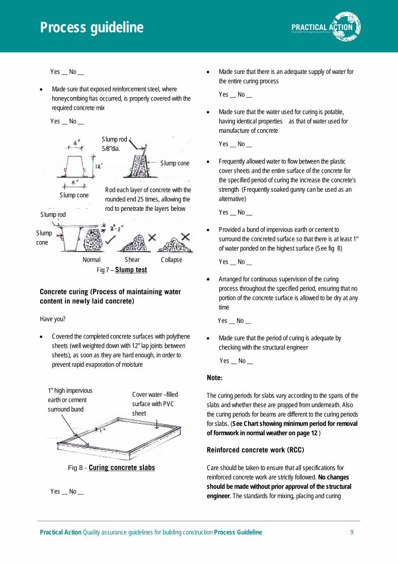
Covered the completed concrete surfaces with polythene sheets (well weighted down with 12” lap joints between sheets), as soon as they are hard enough, in order to prevent rapid evaporation of moisture
Yes __ No __
Made sure that there is an adequate supply of water for the entire curing process
Yes __ No __
Made sure that the water used for curing is potable, having identical properties as that of water used for manufacture of concrete
Yes __ No __
Frequently allowed water to flow between the plastic cover sheets and the entire surface of the concrete for the specified period of curing the increase the concrete’s strength (Frequently soaked gunny can be used as an alternative)
Yes __ No __
Provided a bund of impervious earth or cement to surround the concreted surface so that there is at least 1” of water ponded on the highest surface (See fig 8)
Yes __ No __
Arranged for continuous supervision of the curing process throughout the specified period, ensuring that no portion of the concrete surface is allowed to be dry at any time
Yes __ No __
Made sure that the period of curing is adequate by checking with the structural engineer
Yes __ No __
Note:
The curing periods for slabs vary according to the spans of the slabs and whether these are propped from underneath. Also the curing periods for beams are different to the curing periods for slabs. (See Chart showing minimum period for removal of formwork in normal weather on page 12 )
Reinforced concrete work (RCC)
Care should be taken to ensure that all specifications for reinforced concrete work are strictly followed. No changes should be made without prior approval of the structural engineer. The standards for mixing, placing and curing
Cover water –filled surface with PVC sheet
1” high impervious earth or cement surround bund
Fig 8 - Curing concrete slabs
Slump cone
Slump rod 5/8”dia.
Rod each layer of concrete with the rounded end 25 times, allowing the rod to penetrate the layers below
Slump cone
Slump rod
Slump cone
Normal Shear Collapse
Fig 7 – Slump test

Process guideline
Practical Action Quality assurance guidelines for building construction Process Guideline 10
described in the previous section (concrete work) applies to RCC work as well. Additional standards related to RCC work such as reinforcement fabrication, concrete cover, lapping of steel and other specifications for RCC column, beam and slab construction are listed below.
Reinforcement steel bending and forming of reinforcement cages
Have You?
Used reliable (even if improvised) bar bending apparatus to bend all main reinforcements to the specified dimensions
Yes __ No __
Made sure that all bars are bent cold
Yes __ No __
Made sure that all sizes (diameters & lengths) specified for bottom steel, top steel, distribution steel, stirrups, binders, etc. are strictly according to given specifications
Yes __ No __
Used a reliable method to ensure that reinforcement cages are Correctly sized whether fitted in-situ or pre-fabricated (See fig. 9A)
Yes __ No __
A practical method of reinforcement cage fabrication is by using two (02) trestles to support the two main top bars, then feeding stirrups and bottom bars (See fig. 9B)
Made sure that the binding wire fixed at intersections of main bars and stirrups are cut off and bent inwards so that they cannot rust and show through the concrete
Yes __ No __
Made sure that the reinforcements are accurately placed according to given specifications
Yes __ No __
Lapping of reinforcement
Have You?
Made sure that the specified lap dimensions (length/s of lap given for bars that overlap) for reinforcements are strictly followed for columns, beams and slabs
Yes __ No __
Ensured that bars that lap are cranked (bent to accommodate the overlapping bar) properly (See fig. 10 )
Yes __ No __
Sturdy framed support
Bottom bar
Top bar Stirrup
Fig 9B - Fabricating reinforcements
Step 1 Fabricate stirrups uniformly to specified size
Fig 9A - Fabricating reinforcements
Top steel
Bottom steel
Stirrups
Step 2 Attach prefabricated stirrups to main bars (top/ bottom steel) with binding wire
Binding wire

Process guideline
Practical Action Quality assurance guidelines for building construction Process Guideline 11
Cover to reinforcement
Cover to concrete is the minimum thickness of concrete provided over the reinforcement steel measured from the exposed concrete to the closest reinforced steel surface. Cover is required to protect the reinforcement steel within. The cover should therefore be strong, wear-resistant, dense and having low permeability.
Have You?
Made sure that the specified concrete cover to reinforcements – in columns, beams and slabs etc. – have been strictly adhered to(Cover dimensions are not the same in walls, columns, floor slabs, beams and foundations. The cover should be beyond stirrups and binders)
Yes __ No __
General guidelines for cover to reinforcements in instances where cover specifications are not provided:
Note:
In locations that are affected by salty air (from the sea), it is important to increase the cover, as per the structural engineer’s specifications. The purpose for doing so is to prevent rusting of reinforcements due to the effect of salt.
Have You?
Used spacer blocks (mortar blocks) that are comparable in strength, durability, porosity and appearance to the surrounding concrete (See fig. 11)
Yes __ No __
Checked the reinforcement and cover dimensions before and during the pouring of concrete to make sure that the specified cover is maintained
Yes __ No __
Made sure that the spacing of spacer blocks do not exceed the maximum allowable distance of 3’ – 0”
Yes __ No __
Note:
If wooden spacer blocks are used under reinforcements they should be of adequate strength to support reinforcements. They should also be removed subsequently.
Formwork
Have You?
Made sure that the props that are used are capable of carrying the load of the concrete that they support
Yes __ No __
Lap=50 X bar diameter
Lap
Note: Lap length vertically 30 X bar diameter
Fig 10 - Detail of lap & crank in vertical reinforcements
Starter bars
Floor
Detail of lap in horizontal reinforcements
Footiing
Crank
Lap
Wire to be tied to reinforcement
Fig 11- Typical spacer block
Foundations – 2” to 3”
Columns – 1 ½ “
Beams – 1 ½”
Slabs & stairs – 1 ½”

Process guideline
Practical Action Quality assurance guidelines for building construction Process Guideline 12
Erected the props so that they have firm bearing, using spreaders where needed on sub grades or bases that are weak
Yes __ No __
Made sure that dirt, wood shavings, nails etc. are removed from the formwork, prior to commencement of concreting
Yes __ No __
Striking (removal) off formwork – (see also formwork checklist-pg.)
Formwork must be struck (removed) when the concrete has gained enough strength to be self supporting and also carry any other loads that may be put on it. The times required are usually specified in the drawings or specifications.
Have You?
Designed the formwork so that it can be struck (removed) without damaging the concrete or the form itself
Yes __ No __
Carefully removed wooden spacer blocks soon after the concrete is cured so as to avoid damaging the concrete if removed later
Yes __ No __
Allowed the full specified period for curing to pass before removal of formwork for slabs, beams, columns etc. – (The standard period for most concrete work is 7 days; however this is increased in slabs according to the distance spanned by the beams and slabs – See chart above)
Yes __ No __
Hand mixing of concrete
When concrete is hand mixed – materials in the mix should be turned over completely with a shovel at least twice dry and twice wet. Mixing should be done until the mix is of a uniform colour.
Lintels
Have You?
Made sure that the sizes of lintels and forcements are as specified
Yes_ No_
Made sure that the ends of lintels have adequate bearing on the walls on which they rest. Bearings of lintels over walls are: 6” for brick walls, 9” for random rubble walls (See Fig.12)
Yes __ No __
Minimum period for removing formwork in normal weather:
Days
1. Walls, columns, and vertical sides of beams 1 to 2
2. Slabs (props to be re-fixed immediately after removal of formwork)
3
3. Beam soffits (props to be re-fixed immediately after removal of formwork) Spanning up to 19’ – 6” Spanning over 19’ – 6”
7
14
21
4.Removal of props in slabs: Spanning up to 14’-9” Spanning over 14’-9” up to 19’- 6” Spanning over 19’- 6”
7
14
21
Lintel
Opening
Brick wall
Fig 12 - End bearing for lintels
Lintel
Stone wall
Opening
Process guideline
Practical Action Quality assurance guidelines for building construction Process Guideline 13
Made sure that each RC lintel is of adequate depth – (For ordinary loads take 6” depth for spans up to 4’ and add 1” for each 1’ span)
Yes __ No __
Made sure that the lintels have been kept propped up during bricklaying above the lintel, till the mortar has fully set
Yes __ No __
Made sure that if lintels are cast insitu – these are treated as beams in terms of formwork and propping
Yes __ No __
Masonry work (brick work)
Have you?
Soaked the bricks in water for at least one hour before use
Yes __ No __
Made sure mortar joints are not less than 3/16” or no more than 3/8” thick and laid uniformly so that bricks are laid on a full bed of mortar
Yes __ No __
Thoroughly cleaned the surface of bricks at all mortar joints before laying the next course on top in order to preserve the appearance of the brick
Yes __ No __
Made sure that each brick is properly bedded by gently tapping with the handle of the trowel or wooden mallet
Yes __ No __
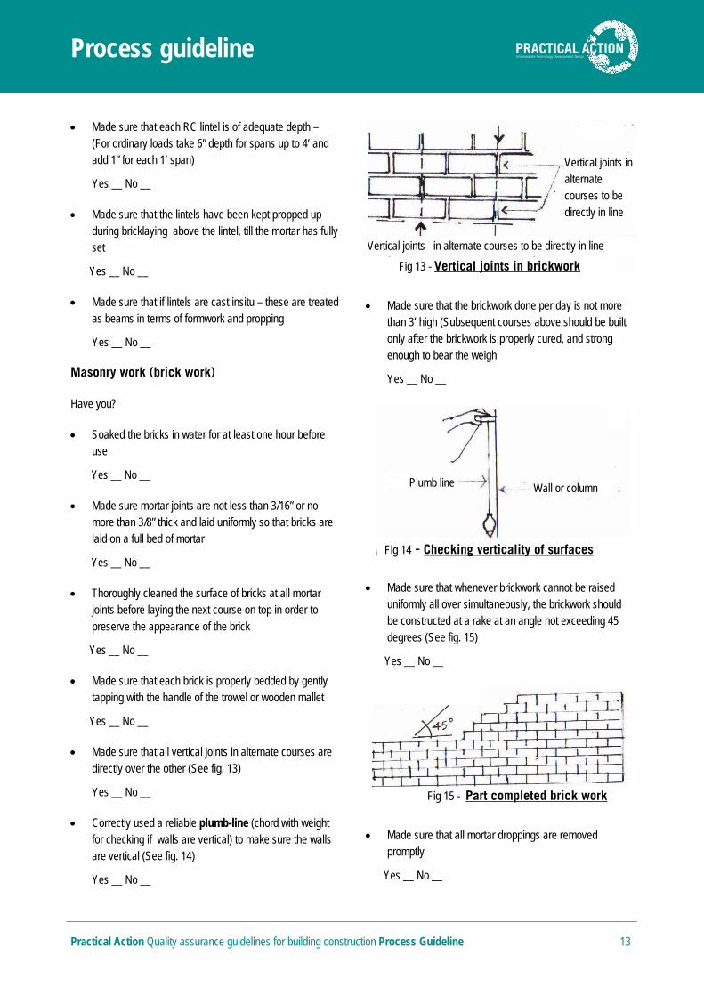
Made sure that all vertical joints in alternate courses are directly over the other (See fig. 13)
Yes __ No __
Correctly used a reliable plumb-line (chord with weight for checking if walls are vertical) to make sure the walls are vertical (See fig. 14)
Yes __ No __
Made sure that the brickwork done per day is not more than 3’ high (Subsequent courses above should be built only after the brickwork is properly cured, and strong enough to bear the weigh
Yes __ No __
Made sure that whenever brickwork cannot be raised uniformly all over simultaneously, the brickwork should be constructed at a rake at an angle not exceeding 45 degrees (See fig. 15)
Yes __ No __
Made sure that all mortar droppings are removed promptly
Yes __ No __
Vertical joints in alternate courses to be directly in line
Vertical joints in alternate courses to be directly in line
Fig 13 - Vertical joints in brickwork
Fig 15 - Part completed brick work
Plumb line Wall or column
Fig 14 - Checking verticality of surfaces
Process guideline
Practical Action Quality assurance guidelines for building construction Process Guideline 14
Effectively protected brick walls in which the mortar is green (fresh), by means of a waterproof material (fabric)
Yes __ No __
Made sure that all masonry work has been kept moist on all surfaces for a minimum period of seven days for proper curing before plastering
Yes __ No __
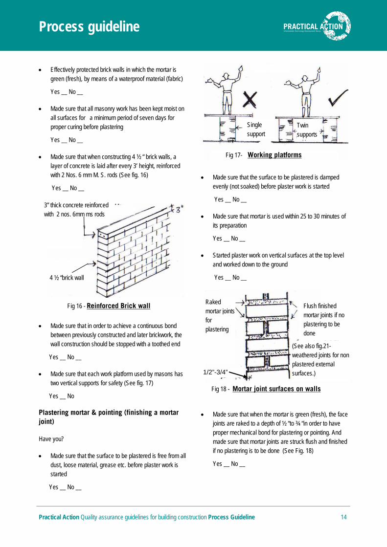
Made sure that when constructing 4 ½ “ brick walls, a layer of concrete is laid after every 3’ height, reinforced with 2 Nos. 6 mm M. S. rods (See fig. 16)
Yes __ No __
Made sure that in order to achieve a continuous bond between previously constructed and later brickwork, the wall construction should be stopped with a toothed end
Yes __ No __
Made sure that each work platform used by masons has two vertical supports for safety (See fig. 17)
Yes __ No
Plastering mortar & pointing (finishing a mortar joint)
Have you?
Made sure that the surface to be plastered is free from all dust, loose material, grease etc. before plaster work is started
Yes __ No __
Made sure that the surface to be plastered is damped evenly (not soaked) before plaster work is started
Yes __ No __
Made sure that mortar is used within 25 to 30 minutes of its preparation
Yes __ No __
Started plaster work on vertical surfaces at the top level and worked down to the ground
Yes __ No __
Made sure that when the mortar is green (fresh), the face joints are raked to a depth of ½ “to ¾ “in order to have proper mechanical bond for plastering or pointing. And made sure that mortar joints are struck flush and finished if no plastering is to be done (See Fig. 18)
Yes __ No __
Fig 17- Working platforms
Single support
Twin supports
Flush finished mortar joints if no plastering to be done
(See also fig.21-weathered joints for non plastered external surfaces.)
Raked mortar joints for plastering
Fig 18 - Mortar joint surfaces on walls
1/2”-3/4”
3” thick concrete reinforced with 2 nos. 6mm ms rods
4 ½ “brick wall
Fig 16 - Reinforced Brick wall
Process guideline
Practical Action Quality assurance guidelines for building construction Process Guideline 15
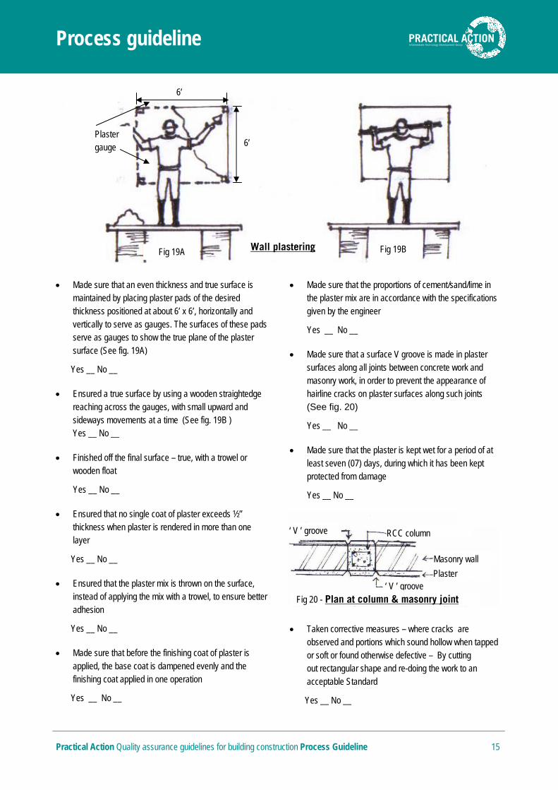
Made sure that an even thickness and true surface is maintained by placing plaster pads of the desired thickness positioned at about 6’ x 6’, horizontally and vertically to serve as gauges. The surfaces of these pads serve as gauges to show the true plane of the plaster surface (See fig. 19A)
Yes __ No __
Ensured a true surface by using a wooden straightedge reaching across the gauges, with small upward and sideways movements at a time (See fig. 19B ) Yes __ No __
Finished off the final surface – true, with a trowel or wooden float
Yes __ No __
Ensured that no single coat of plaster exceeds ½” thickness when plaster is rendered in more than one layer
Yes __ No __
Ensured that the plaster mix is thrown on the surface, instead of applying the mix with a trowel, to ensure better adhesion
Yes __ No __
Made sure that before the finishing coat of plaster is applied, the base coat is dampened evenly and the finishing coat applied in one operation
Yes __ No __
Made sure that the proportions of cement/sand/lime in the plaster mix are in accordance with the specifications given by the engineer
Yes __ No __
Made sure that a surface V groove is made in plaster surfaces along all joints between concrete work and masonry work, in order to prevent the appearance of hairline cracks on plaster surfaces along such joints (See fig. 20)
Yes __ No __
Made sure that the plaster is kept wet for a period of at least seven (07) days, during which it has been kept protected from damage
Yes __ No __
Taken corrective measures – where cracks are observed and portions which sound hollow when tapped or soft or found otherwise defective – By cutting out rectangular shape and re-doing the work to an acceptable Standard
Yes __ No __
‘ V ’ groove
RCC column
Masonry wall
Plaster
‘ V ’ groove
Fig 20 - Plan at column & masonry joint
Fig 19B Wall plastering
Plaster gauge
Fig 19A
6’
6’
Process guideline
Practical Action Quality assurance guidelines for building construction Process Guideline 16
Made sure, where wall surfaces have to be plastered that all joints in the masonry are raked out to a depth of at least ½” with a hooked tool, while the mortar is still green; doing so without damaging the edges of bricks before pointing is done
Yes __ No __
Ensured that pointing is done while the mortar in the joint is still green
Yes __ No __
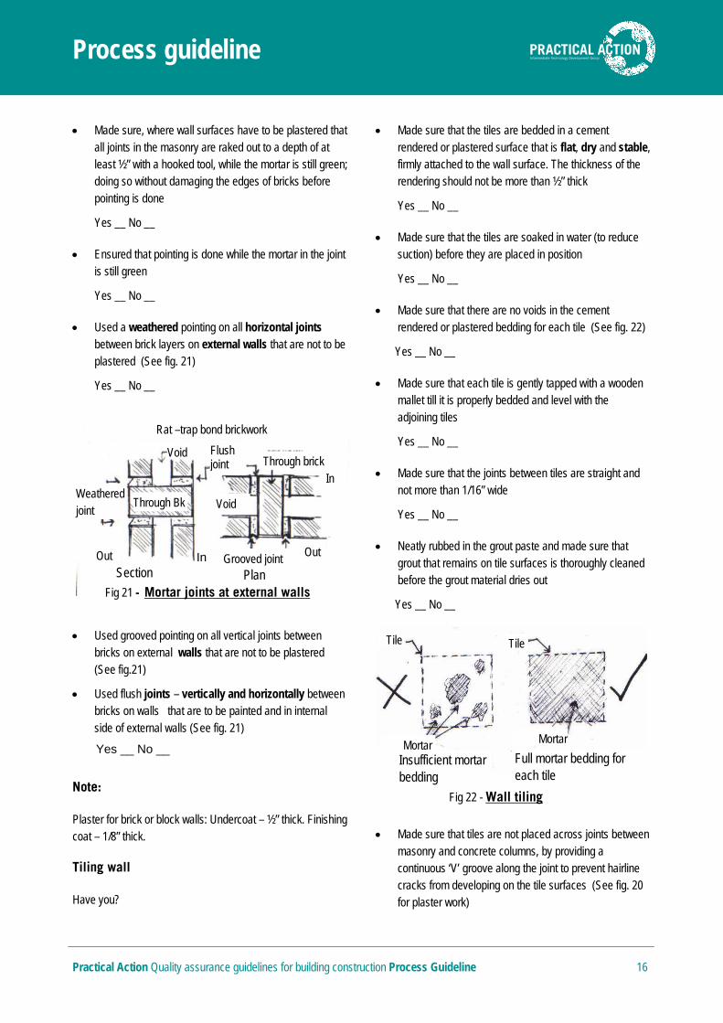
Used a weathered pointing on all horizontal joints between brick layers on external walls that are not to be plastered (See fig. 21)
Yes __ No __
Used grooved pointing on all vertical joints between bricks on external walls that are not to be plastered (See fig.21)
Used flush joints – vertically and horizontally between bricks on walls that are to be painted and in internal side of external walls (See fig. 21)
Yes __ No __
Note:
Plaster for brick or block walls: Undercoat – ½” thick. Finishing coat – 1/8” thick.
Tiling wall
Have you?
Made sure that the tiles are bedded in a cement rendered or plastered surface that is flat, dry and stable, firmly attached to the wall surface. The thickness of the rendering should not be more than ½” thick
Yes __ No __
Made sure that the tiles are soaked in water (to reduce suction) before they are placed in position
Yes __ No __
Made sure that there are no voids in the cement rendered or plastered bedding for each tile (See fig. 22)
Yes __ No __
Made sure that each tile is gently tapped with a wooden mallet till it is properly bedded and level with the adjoining tiles
Yes __ No __
Made sure that the joints between tiles are straight and not more than 1/16” wide
Yes __ No __
Neatly rubbed in the grout paste and made sure that grout that remains on tile surfaces is thoroughly cleaned before the grout material dries out
Yes __ No __
Made sure that tiles are not placed across joints between masonry and concrete columns, by providing a continuous ‘V’ groove along the joint to prevent hairline cracks from developing on the tile surfaces (See fig. 20 for plaster work)
Fig 21 - Mortar joints at external walls
Section
Out
In
Grooved joint Out
Through brick
In
Flush joint
Void Weathered joint
Void
Rat –trap bond brickwork
Plan
Through Bk
Fig 22 - Wall tiling
Full mortar bedding for each tile
Insufficient mortar bedding
Tile Tile
Mortar Mortar

Process guideline
Practical Action Quality assurance guidelines for building construction Process Guideline 17
Yes __ No __
Floors
Have you?
Made sure that all earth filling under the floors is thoroughly rammed and consolidated by placing 6” layers of earth at a time and spraying its surface with water to achieve maximum compaction
Yes __ No __
Made sure that the ground surface is well watered and level before placing the bricks
Yes __ No __
Made sure that the bricks are well soaked before placing them flat on a ½” thick mortar bed, and with vertical mortar joints that are quite full
Yes __ No __
(Alternatively bricks can be placed on edge if specified)
Made sure that the 5/8” thick cement rendering is properly level by placing the concrete within alternate 6’x 6’ bays with screeding gauges (Screed mounds to 5/8” thickness) at four corners of each square bay and trowel led smooth (See fig. 23)
Yes __ No __
Used a spirit level (Instrument to check if level is horizontal) to check if the floor is level
Yes __ No __
Made sure that the finished floor is protected from sun and rain, and kept moist for 10 to 15 days
Yes __ No __
Tiling floor
Have you?
Made sure that the base cement rendering on which the tiles are to be laid is according to the tile manufacturer’s specifications. (Usually 1:1:6 cement/lime/sand or 1:8 cement sand to a thickness of 3/8” to 1”)
Yes __ No __
Made sure that the floor tiles chosen are not with high gloss surfaces that are dangerous, because people can slip on the surfaces
Yes __ No __
Made sure that there are no voids in the cement rendering under each tile to ensure the stability of each tile (See fig. 24)
Yes __ No __
Made sure that the gap between tiles is not more than 1/16” and that each tile is tapped lightly with a wooden mallet till it is properly bedded and in level with the adjoining tiles
Yes __ No __
Fig 23 - Laying floor screed
Scrceeding gauge Screeding gauge
Tile
Full mortar bedding
Tile
Insufficient mortar bedding
Fig 24 - Floor tiling
Process guideline
Practical Action Quality assurance guidelines for building construction Process Guideline 18
Made sure that the tiles are laid level and the grouting placed neatly and the excess grout material is immediately cleaned off the tile surfaces
Yes __ No __
Made sure that placement of tiles begins only after the bedding has become sufficiently hard to offer a rigid cushion for the tiles
Yes __ No __
Made sure that neat cement slurry of even consistency is spread over the mortar bed over an area enough to cover about 20 standard sized square tiles
Yes __ No __
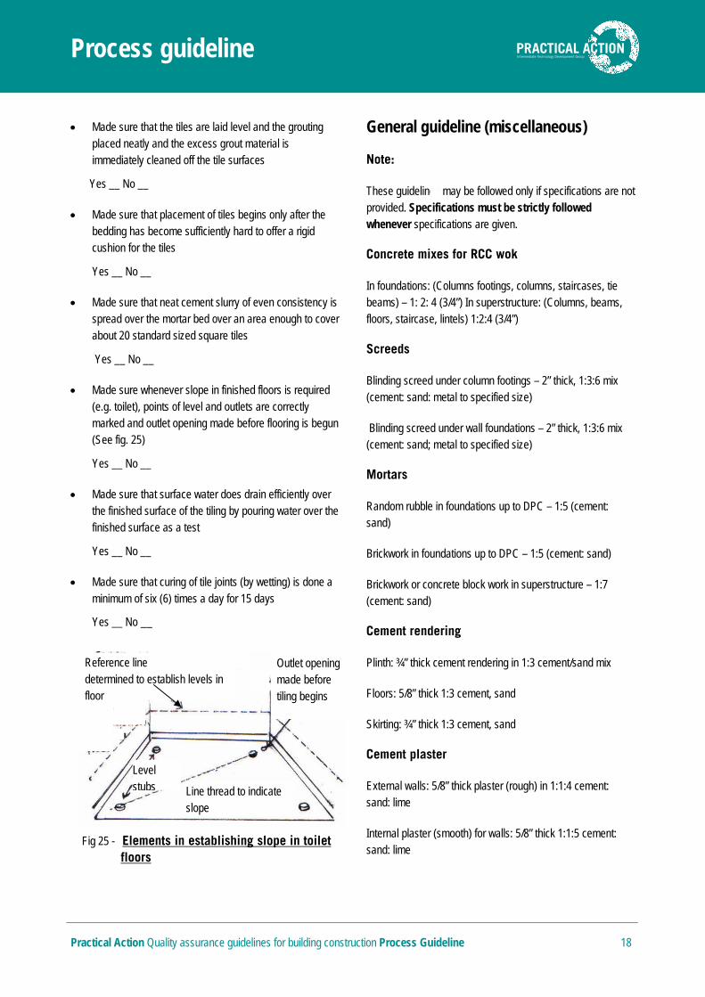
Made sure whenever slope in finished floors is required (e.g. toilet), points of level and outlets are correctly marked and outlet opening made before flooring is begun (See fig. 25)
Yes __ No __
Made sure that surface water does drain efficiently over the finished surface of the tiling by pouring water over the finished surface as a test
Yes __ No __
Made sure that curing of tile joints (by wetting) is done a minimum of six (6) times a day for 15 days
Yes __ No __
General guideline (miscellaneous)
Note:
These guidelines may be followed only if specifications are not provided. Specifications must be strictly followed whenever specifications are given.
Concrete mixes for RCC wok
In foundations: (Columns footings, columns, staircases, tie beams) – 1: 2: 4 (3/4”) In superstructure: (Columns, beams, floors, staircase, lintels) 1:2:4 (3/4”)
Screeds
Blinding screed under column footings – 2” thick, 1:3:6 mix (cement: sand: metal to specified size)
Blinding screed under wall foundations – 2” thick, 1:3:6 mix (cement: sand; metal to specified size)
Mortars
Random rubble in foundations up to DPC – 1:5 (cement: sand)
Brickwork in foundations up to DPC – 1:5 (cement: sand)
Brickwork or concrete block work in superstructure – 1:7 (cement: sand)
Cement rendering
Plinth: ¾” thick cement rendering in 1:3 cement/sand mix
Floors: 5/8” thick 1:3 cement, sand
Skirting: ¾” thick 1:3 cement, sand
Cement plaster
External walls: 5/8” thick plaster (rough) in 1:1:4 cement: sand: lime
Internal plaster (smooth) for walls: 5/8” thick 1:1:5 cement: sand: lime
Fig 25 - Elements in establishing slope in toilet floors
Outlet opening made before tiling begins
Line thread to indicate slope
Reference line to be first determined to establish levels in floor
Level stubs
Process guideline
Practical Action Quality assurance guidelines for building construction Process Guideline 19
Internal plaster (smooth) for beam soffits, columns, slabs and staircase etc. 5/8” thick 1:3 finished smooth with neat lime putty
Damp proof course (DPC)
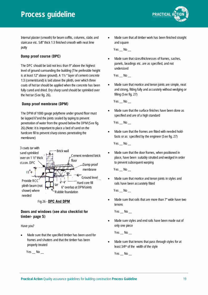
The DPC should be laid not less than 9” above the highest level of ground surrounding the building (The preferable height is at least 12” above ground). A 1½ “ layer of cement concrete 1:3 (cement/sand) is laid above the plinth, over which three coats of hot tar should be applied when the concrete has been fully cured and dried. Dry sharp sand should be sprinkled over the hot tar (See fig. 26).
Damp proof membrane (DPM)
The DPM of 1000 gauge polythene under ground floor must be lapped 6”and the joints sealed by taping to prevent penetration of water from the ground below the DPM (See fig. 26).(Note: it is important to place a bed of sand on the hardcore fill to prevent sharp stones penetrating the membrane)
Doors and windows (see also checklist for timber- page 5)
Have you?
Made sure that the specified timber has been used for frames and shutters and that the timber has been properly treated
Yes __ No __
Made sure that all timber work has been finished straight and square
Yes __ No __
Made sure that sizes/thicknesses of frames, sashes, panels, beadings etc. are as specified, and not undersized
Yes __ No __
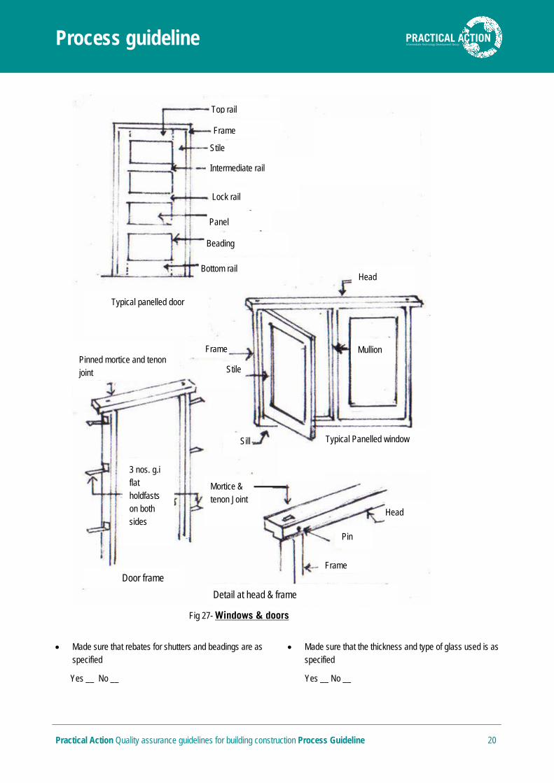
Made sure that mortice and tenon joints are simple, neat and strong, fitting fully and accurately without wedging or filling (See fig. 27)
Yes __ No __
Made sure that the surface finishes have been done as specified and are of a high standard
Yes __ No __
Made sure that the frames are fitted with needed hold-fasts or as specified by the engineer (See fig. 27)
Yes __ No __
Made sure that the door frames, when positioned in place, have been suitably strutted and wedged in order to prevent subsequent warping
Yes __ No __
Made sure that mortice and tenon joints in styles and rails have been accurately fitted
Yes __ No __
Made sure that rails that are more than 7” wide have two tenons
Yes __ No __
Made sure styles and end rails have been made out of only one piece
Yes __ No __
Made sure that tenons that pass through styles for at least 3/4th of the width of the style
Yes __ No __
3 coats tar with sand sprinkled over on 1 ½” thick ct.con. DPC
Provide RCC plinth beam (not shown) where needed
Brick wall Cement rendered brick floor
Damp proof membrane
Ground level
Hard core fill
Rubble foundation 6” overlap at DPM joints
tar
Fig 26 - DPC And DPM
Process guideline
Practical Action Quality assurance guidelines for building construction Process Guideline 20
Made sure that rebates for shutters and beadings are as specified
Yes __ No __
Made sure that the thickness and type of glass used is as specified
Yes __ No __
Stile
Top rail
Frame
Stile
Intermediate rail
Lock rail
Panel
Beading
Bottom rail
Fig 27- Windows & doors
Typical panelled door
Frame
Pinned mortice and tenon joint
Head
Sill
Mortice & tenon Joint
Typical Panelled window
Detail at head & frame
Door frame
3 nos. g.i flat holdfasts on both sides
Frame
Pin
Head
Mullion
Process guideline
Practical Action Quality assurance guidelines for building construction Process Guideline 21
Made sure that all ironmongery used are as specified and of good quality Yes __ No __
See figure 27 above for illustrations of above-named elements in doors and windows
Roof work
RCC roofs (cast - insitu)
Have you?
Made sure that a continuous RCC ring beam has been provided at the top of all perimeter masonry walls as well as load-bearing internal walls in order to anchor the proposed RCC flat roof
Yes __ No __
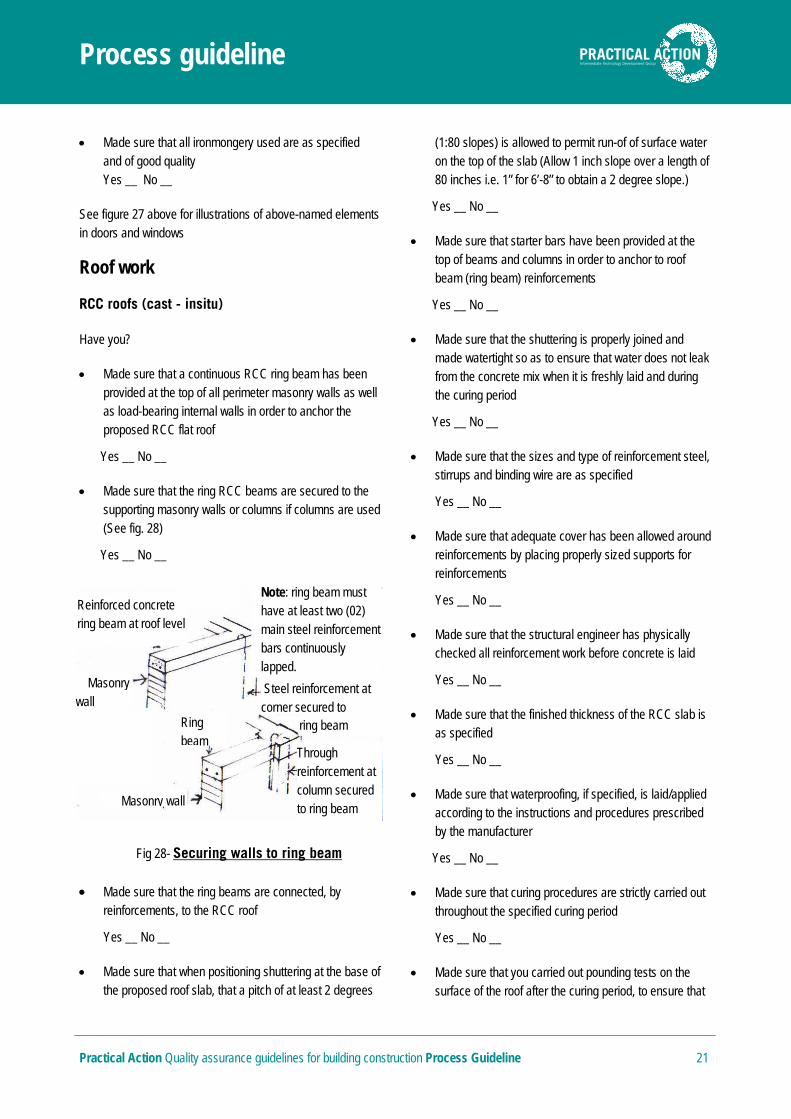
Made sure that the ring RCC beams are secured to the supporting masonry walls or columns if columns are used (See fig. 28)
Yes __ No __
Made sure that the ring beams are connected, by reinforcements, to the RCC roof
Yes __ No __
Made sure that when positioning shuttering at the base of the proposed roof slab, that a pitch of at least 2 degrees
(1:80 slopes) is allowed to permit run-of of surface water on the top of the slab (Allow 1 inch slope over a length of 80 inches i.e. 1” for 6’-8” to obtain a 2 degree slope.)
Yes __ No __
Made sure that starter bars have been provided at the top of beams and columns in order to anchor to roof beam (ring beam) reinforcements
Yes __ No __
Made sure that the shuttering is properly joined and made watertight so as to ensure that water does not leak from the concrete mix when it is freshly laid and during the curing period
Yes __ No __
Made sure that the sizes and type of reinforcement steel, stirrups and binding wire are as specified
Yes __ No __
Made sure that adequate cover has been allowed around reinforcements by placing properly sized supports for reinforcements
Yes __ No __
Made sure that the structural engineer has physically checked all reinforcement work before concrete is laid
Yes __ No __
Made sure that the finished thickness of the RCC slab is as specified
Yes __ No __
Made sure that waterproofing, if specified, is laid/applied according to the instructions and procedures prescribed by the manufacturer
Yes __ No __
Made sure that curing procedures are strictly carried out throughout the specified curing period
Yes __ No __
Made sure that you carried out pounding tests on the surface of the roof after the curing period, to ensure that
Reinforced concrete ring beam at roof level
Masonry wall
Note: ring beam must have at least two (02) main steel reinforcement bars continuously lapped.
Steel reinforcement at corner secured to
Through reinforcement at column secured to ring beam
Masonry wall
Fig 28- Securing walls to ring beam
Ring beam
ring beam
Process guideline
Practical Action Quality assurance guidelines for building construction Process Guideline 22
there is no collection of water on the finished surface (See General Guidelines – miscellaneous)
Yes __ No __
Note:
Refer checklists, given previously in this document, for concrete work and reinforced concrete work and ensure that all the instructions in these checklists are strictly carried out.
Clay tile and corrugated gi or zinc-aluminium roofs using timber framework (checklist for metal framework for roofs is not included below)
Have you?
Made sure that all timber members for roofing are duly treated and their ends painted in order to mitigate decay and deterioration of the timber
Yes __ No __
Made sure that the timber sizes specified for wall plates, trusses, rafters, purlins and battens (reapers) are used (smaller sizes must not be used)
Yes __ No __
Made sure that the placement of trusses, rafters, purlins and battens (reapers) are strictly in accordance with the specifications and drawings
Yes __ No __
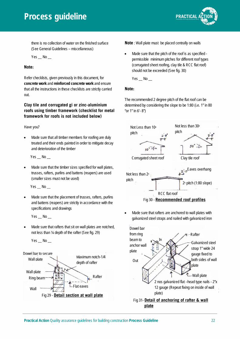
Made sure that rafters that sit on wall plates are notched, not less than ¼ depth of the rafter (See fig. 29)
Yes __ No __
Note : Wall plate must be placed centrally on walls
Made sure that the pitch of the roof is as specified - permissible minimum pitches for different roof types (corrugated sheet roofing, clay tile & RCC flat roof) should not be exceeded (See fig. 30)
Yes __ No __
Note:
The recommended 2 degree pitch of the flat roof can be determined by considering the slope to be 1:80 (i.e. 1” in 80 “or 1” in 6’- 8”)
Made sure that rafters are anchored to wall plates with galvanized steel straps and nailed with galvanized iron
Dowel bar to secure Maximum notch-1/4 depth of rafter
Rafter
Flat eaves
Fig 29 - Detail section at wall plate
Wall
Wall plate
Ring beam
Wall plate
Dowel bar from ring beam to anchor wall plate
Fig 31- Detail of anchoring of rafter & wall plate
Galvanized steel strap 1” wide 24 gauge fixed to both sides of wall plate
Rafter
2 nos galvanized flat –head type nails - 2”x 12 gauge (Repeat fixing on inside of wall plate)
Wall plate
Out
In
Not Less than 100 pitch
Not less than 300 pitch
Corrugated sheet roof Clay tile roof
Not less than 20 pitch
RCC flat roof
Fig 30 - Recommended roof profiles
Eaves overhang
20 pitch (1:80 slope)
Process guideline
Practical Action Quality assurance guidelines for building construction Process Guideline 23
flat-head nails (See fig. 31)
Yes __ No __
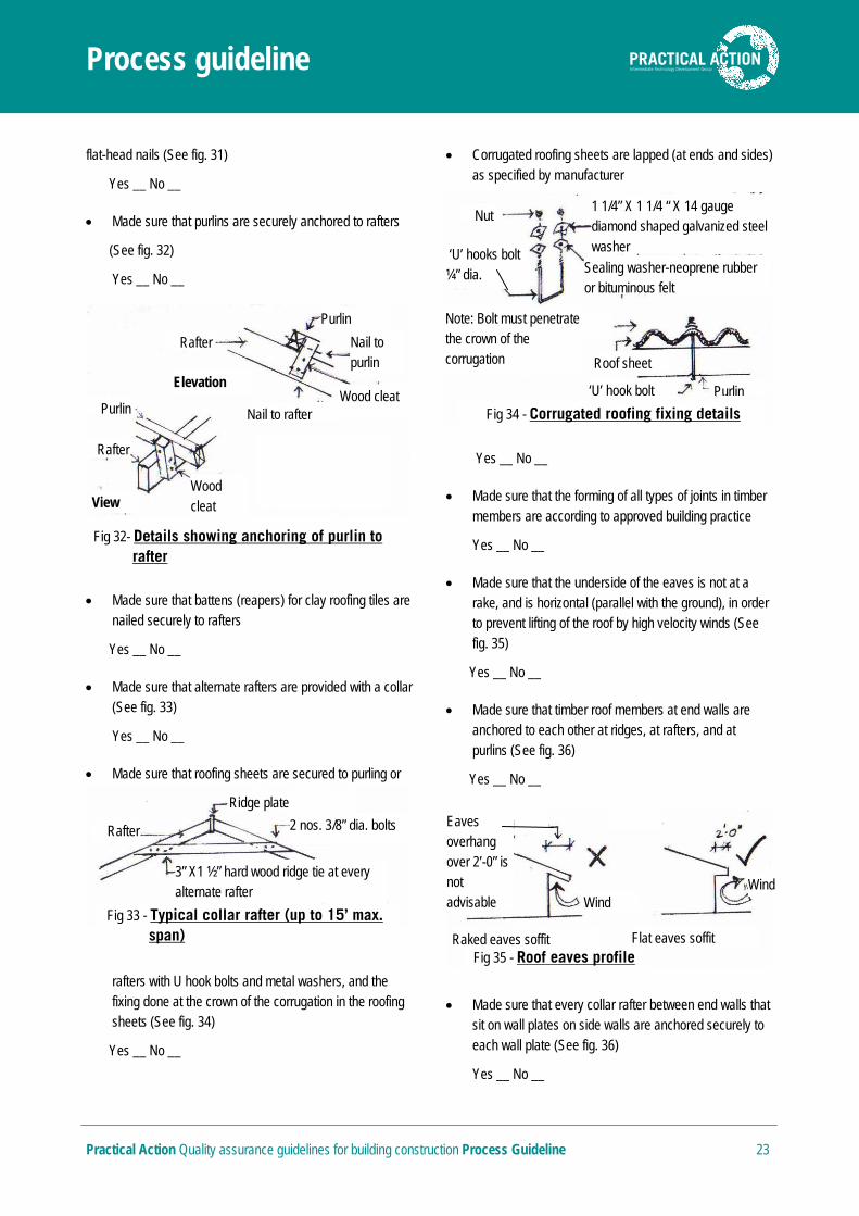
Made sure that purlins are securely anchored to rafters
(See fig. 32)
Yes __ No __
Made sure that battens (reapers) for clay roofing tiles are nailed securely to rafters
Yes __ No __
Made sure that alternate rafters are provided with a collar (See fig. 33)
Yes __ No __
Made sure that roofing sheets are secured to purling or
rafters with U hook bolts and metal washers, and the fixing done at the crown of the corrugation in the roofing sheets (See fig. 34)
Yes __ No __
Corrugated roofing sheets are lapped (at ends and sides) as specified by manufacturer
Yes __ No __
Made sure that the forming of all types of joints in timber members are according to approved building practice
Yes __ No __
Made sure that the underside of the eaves is not at a rake, and is horizontal (parallel with the ground), in order to prevent lifting of the roof by high velocity winds (See fig. 35)
Yes __ No __
Made sure that timber roof members at end walls are anchored to each other at ridges, at rafters, and at purlins (See fig. 36)
Yes __ No __
Made sure that every collar rafter between end walls that sit on wall plates on side walls are anchored securely to each wall plate (See fig. 36)
Yes __ No __
Ridge plate
2 nos. 3/8” dia. bolts Rafter
3” X1 ½” hard wood ridge tie at every alternate rafter
Fig 33 - Typical collar rafter (up to 15’ max. span)
Nut 1 1/4” X 1 1/4 “ X 14 gauge diamond shaped galvanized steel washer
Sealing washer-neoprene rubber or bituminous felt
‘U’ hooks bolt ¼” dia.
Note: Bolt must penetrate the crown of the corrugation Roof sheet
Fig 34 - Corrugated roofing fixing details
‘U’ hook bolt Purlin
Raked eaves soffit Flat eaves soffit Fig 35 - Roof eaves profile
Eaves overhang over 2’-0” is not advisable Wind
Wind
Elevation
Rafter
Purlin
Nail to rafter Wood cleat
Nail to purlin
Fig 32- Details showing anchoring of purlin to rafter
Wood cleat
Purlin
Rafter
View
Process guideline
Practical Action Quality assurance guidelines for building construction Process Guideline 24
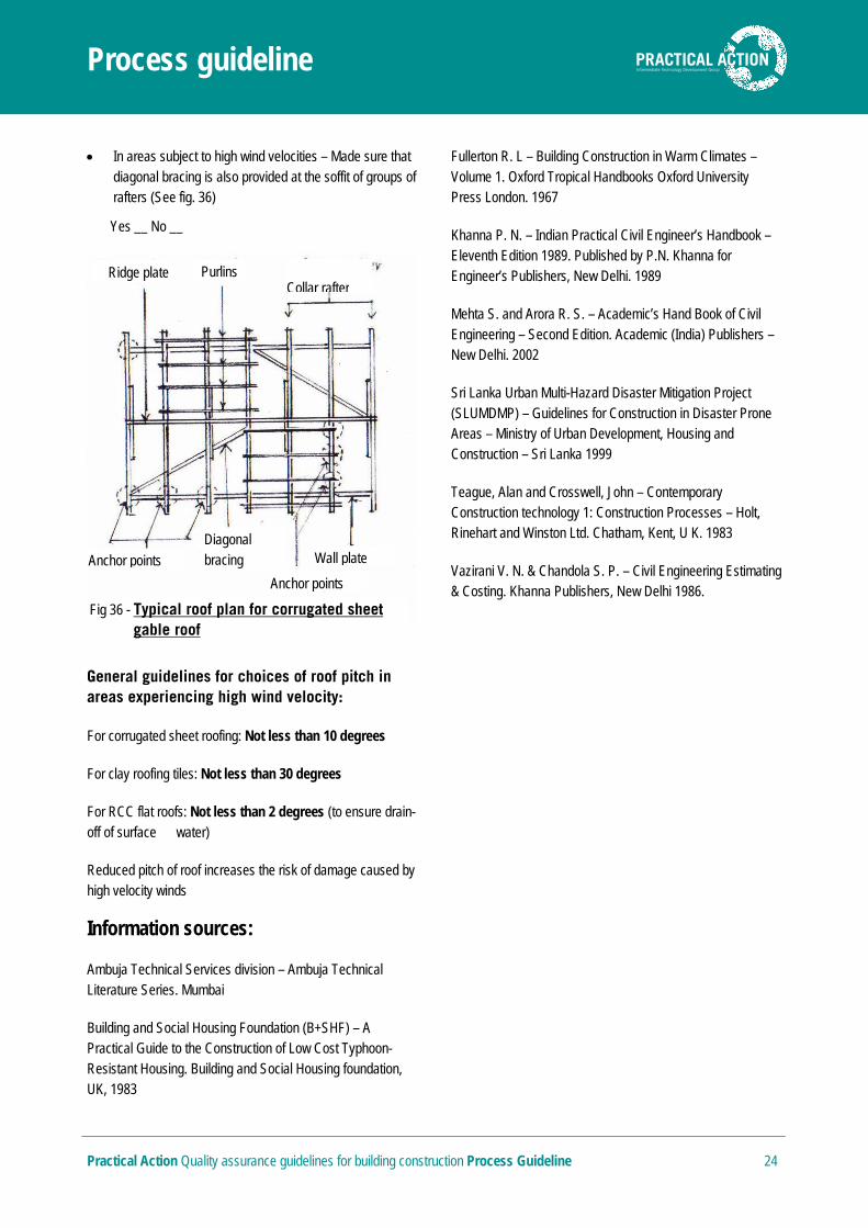
In areas subject to high wind velocities – Made sure that diagonal bracing is also provided at the soffit of groups of rafters (See fig. 36)
Yes __ No __
General guidelines for choices of roof pitch in areas experiencing high wind velocity:
For corrugated sheet roofing: Not less than 10 degrees
For clay roofing tiles: Not less than 30 degrees
For RCC flat roofs: Not less than 2 degrees (to ensure drain-off of surface water)
Reduced pitch of roof increases the risk of damage caused by high velocity winds
Information sources:
Ambuja Technical Services division – Ambuja Technical Literature Series. Mumbai
Building and Social Housing Foundation (B+SHF) – A Practical Guide to the Construction of Low Cost Typhoon-Resistant Housing. Building and Social Housing foundation, UK, 1983
Fullerton R. L – Building Construction in Warm Climates – Volume 1. Oxford Tropical Handbooks Oxford University Press London. 1967
Khanna P. N. – Indian Practical Civil Engineer’s Handbook – Eleventh Edition 1989. Published by P.N. Khanna for Engineer’s Publishers, New Delhi. 1989
Mehta S. and Arora R. S. – Academic’s Hand Book of Civil Engineering – Second Edition. Academic (India) Publishers – New Delhi. 2002
Sri Lanka Urban Multi-Hazard Disaster Mitigation Project (SLUMDMP) – Guidelines for Construction in Disaster Prone Areas – Ministry of Urban Development, Housing and Construction – Sri Lanka 1999
Teague, Alan and Crosswell, John – Contemporary Construction technology 1: Construction Processes – Holt, Rinehart and Winston Ltd. Chatham, Kent, U K. 1983
Vazirani V. N. & Chandola S. P. – Civil Engineering Estimating & Costing. Khanna Publishers, New Delhi 1986.
Purlins Ridge plate
Collar rafter
Diagonal bracing Wall plate
Anchor points
Anchor points
Fig 36 - Typical roof plan for corrugated sheet gable roof