quality assurance of large area rpc detector : techniques for measurement of gas leak rate by...
TRANSCRIPT
QUALITY ASSURANCE OF LARGE AREA RPC DETECTOR :
TECHNIQUES FOR MEASUREMENT OF GAS LEAK RATE
By Avinash V. JoshiAlpha Pneumatics , Mumbai (India)
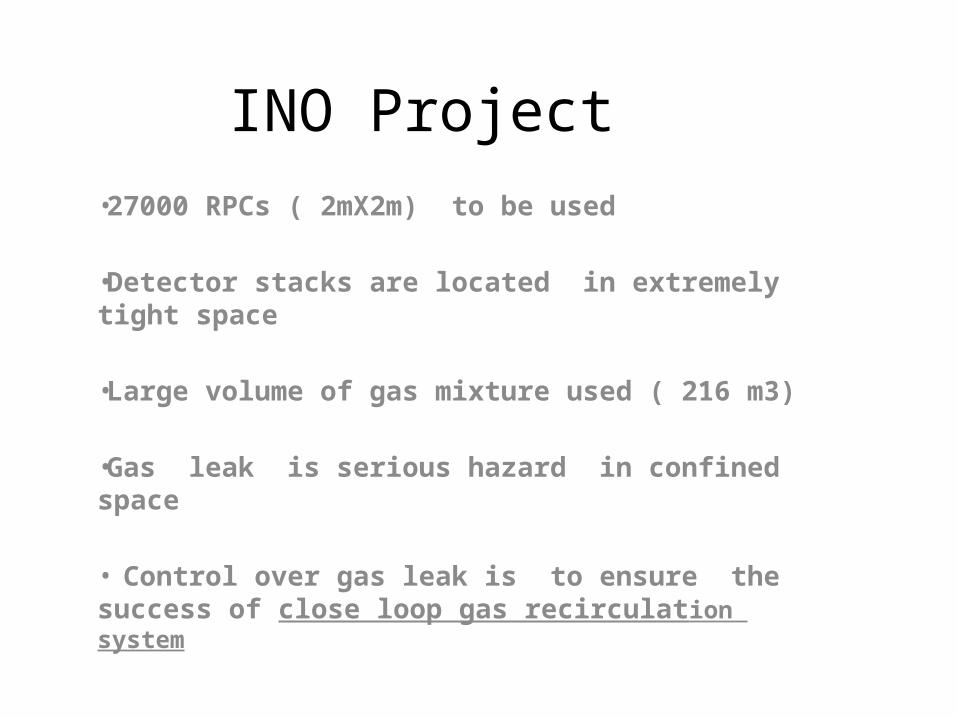
INO Project •27000 RPCs ( 2mX2m) to be used
•Detector stacks are located in extremely tight space
•Large volume of gas mixture used ( 216 m3)
•Gas leak is serious hazard in confined space
• Control over gas leak is to ensure the success of close loop gas recirculation system
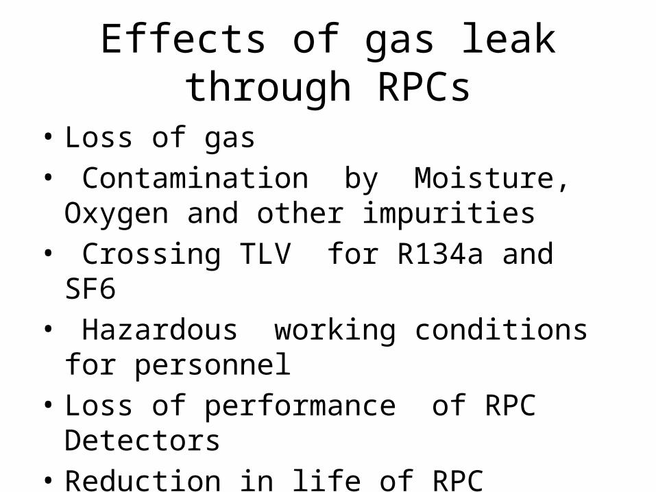
Effects of gas leak through RPCs
• Loss of gas• Contamination by Moisture, Oxygen and
other impurities• Crossing TLV for R134a and SF6• Hazardous working conditions for personnel• Loss of performance of RPC Detectors• Reduction in life of RPC Detectors

Where J= the flux ( mol/m2 .sec) D = Diffusivity of the material (m2/sec) Φ = Concentration of material (mol/m3) x = distance along x direction (m)
• By Fick’s First Law of Diffusion
Diffusion of contaminants into RPC

Diffusion of contaminants into RPC By applying Fick’s Second law of diffusion to one dimensional diffusion from an infinite source we get:
By applying Taylor Series approximation to (2):
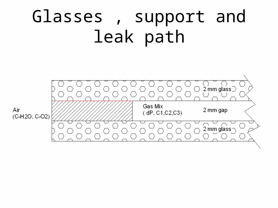
Glasses , support and leak path
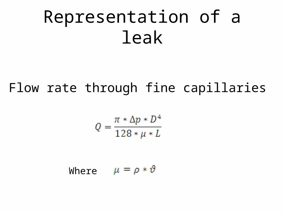
Representation of a leak
As Flow rate through fine capillaries
Where

Representation of a Leak

Aim : Leak rate control
1. Quantitative Definition of “ Acceptable range of leak rate” for 2 m x 2m glass RPCs
2. Reliable testing method for Acceptable leak rate , Highly Sensitive and Time Accelerated
3. Equipment and Procedure for measuring leak rate
4. RPC Production techniques to ensure high yield of RPCs with acceptable leak rate at reduced uncertainty

Leak rate and the related factors
• Mass leak rate is an absolute independent of gas pressure and temperature.
• Leak rates of systems working at different operating conditions can be compared and evaluated, if expressed in mass leak rate.
• Volume leak rate is simple to measure and can be converted to mass leak rate by :
PV = nRT to Standard conditions (273K,1BarA)• Measuring units of leak rate are : SCCM , torr*litres/sec.

Operational parameters for flow through RPC
• Flow • pressure• Stagnation : non-uniformity• Uniform ratio of gases throughout cavity.• Ease of Flushing in and out

Case (1) : velocity distribution (m/s) for 1mX1m RPC , 0.2 Volume changes/day

Case (2) : velocity distribution (m/s) for 1mX1m RPC , 0.5 Volume changes/day

Criteria for Acceptable leak rate• Criteria varies for every application • Typical considerations for rpc : i) Open ended systems : 1% of Average flow rate Flow rate depends on volume changes/day and volume changes/day depend upon generation of contamination ( Radicals)
ii) Extent of contamination ingress , a function of Leak rate , stratification and vol. changes/day ,generation rate of contamination and also tolerance level to Radical concentration iii) Closed loop recirculation system : The time interval between complete discharge of one volume change
should be 6 months, in absence of Radicals.

Estimate of leak rate
• Internal volume of 2m X 2m RPC =8000 cc• Minimum number of Volume changes /day = 0.2
under cosmic radiation.• Total volume of gas discarded to atmosphere = 0.2
X 8000 = 1600 cc/day in open mode• A close loop system is ideally required to save 99% • Acceptable wastage rate = 16 cc/ day• Contaminant Flushing rate will be 8 cc/day• Allowable leak rate per RPC = 8 cc/day

Acceptable Leak rate value
• Effective total leakage :(27000 X 8 /1000 )=216 Litres/day
• Equivalent to leaking 1 Kg of R134a /day @ 12 Euro /day
• 8 ml leak in ( 24X60X60) seconds = 10E-4 cc /sec. or 1.3 *10E-4 torr*litres /sec
• Equivalent to 60 X 10E-4 SCCM
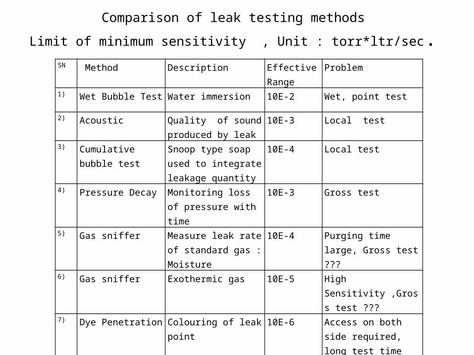
Comparison of leak testing methods
Limit of minimum sensitivity , Unit : torr*ltr/sec.SN Method Description Effective
Range Problem
1) Wet Bubble Test Water immersion 10E-2 Wet, point test
2) Acoustic Quality of sound produced by leak
10E-3 Local test
3) Cumulative bubble test
Snoop type soap used to integrate leakage quantity
10E-4 Local test
4) Pressure Decay Monitoring loss of pressure with time
10E-3 Gross test
5) Gas sniffer Measure leak rate of standard gas :Moisture
10E-4 Purging time large, Gross test ???
6) Gas sniffer Exothermic gas 10E-5 High Sensitivity ,Gross test ???
7) Dye Penetration Colouring of leak point 10E-6 Access on both side required, long test time
8) Helium Leak test Mass Spectrometry 10E-10 High Vacuum required
9) Isotope Tracer Similar to sniffer 10E-11 Hazardous

Accelerated Leak testAcceleration by using faster gas
•Hydrogen is best contender for accelerated leak test due to its low density , low viscosity , high diffusivity and Low background concentration in air• Under laminar flow conditions Hydrogen leaks nearly 10 times faster than R134a or SF6, and about twice faster than Isobutane.• Under turbulent flow conditions , same ratio will be 7 and 5.5 respectively • Hydrogen sniffers with exothermic catalysts have excellent sensitivity even at 1 ppm • Hydrogen diluted by Inert gas ( H2+ Ar) at 1% is very safe to handle
Acceleration by using higher Pressure difference• Under higher than operating pressure difference a leak will be faster by ratio of √ (∆P1/∆P2)

Equation for Gas Leak

Strain over glass plate at 0.2 BarG pressure

Properties of gases
S.N. GAS Mol. Wt Viscosity cP Diffusivity in Air 10E-6 m2/sec
1) Argon 40 0.02099 11
2) Isobutane 58 0.0068 96.4
3) Freon R134a 102 0.034 10
4) Oxygen 32 0.02018 14
5) H2O vapour 18 0.013 24
6) Nitrogen 28 0.017 13
7) Sulphur Hexafluoride
146 0.014 8
8) Hydrogen 2 0.0087 78

Comparison of Leak rates of gases IF Leak rate of Freon R134a , under certain conditions, is considered as 10 units then under same conditions :
1) Isobutane will have leak rate : 50 units
2) SF6 leak rate will be slowest : 3 units.
3) Hydrogen will have fastest leak rate more than 100 units
4) H20 from Air will diffuse into the RPC , against differential pressure , under influence of strong concentration gradient

Comparison Between Pressure decay and Sniffer test under pressure
When 1 SCCM R134a leaks through RPC having 8000 cc volume and at 1020 mBar ,the pressure drop = 1020-1019.875 = 0.125 mBar in a minute
If 55 *10E-4 SCCM gas leaks through RPC under same condition the pressure drop will be 6.8 X10E-4 / minute or 1 mBar in 1470 minutes , or one day
One millibar Pressure change in a sealed RPC can also occur due to Atmospheric pressure changes over a day-night cycle or 0.3 C change in the ambient temperature.The pressure tranducer will not be able to measure leak rate in 10E-4 SCCM range.
On the other hand the equivalent H2 inward leak rate is at least 20 times faster and equal to 1000 10E-4 SCCM or 10E-1 SCCM
10E-1 SCCM Hydrogen in purge Argon flow of 100 SCCM = 1000 ppm which is 1000 times more than the sensitivity of Hydrogen sensor.
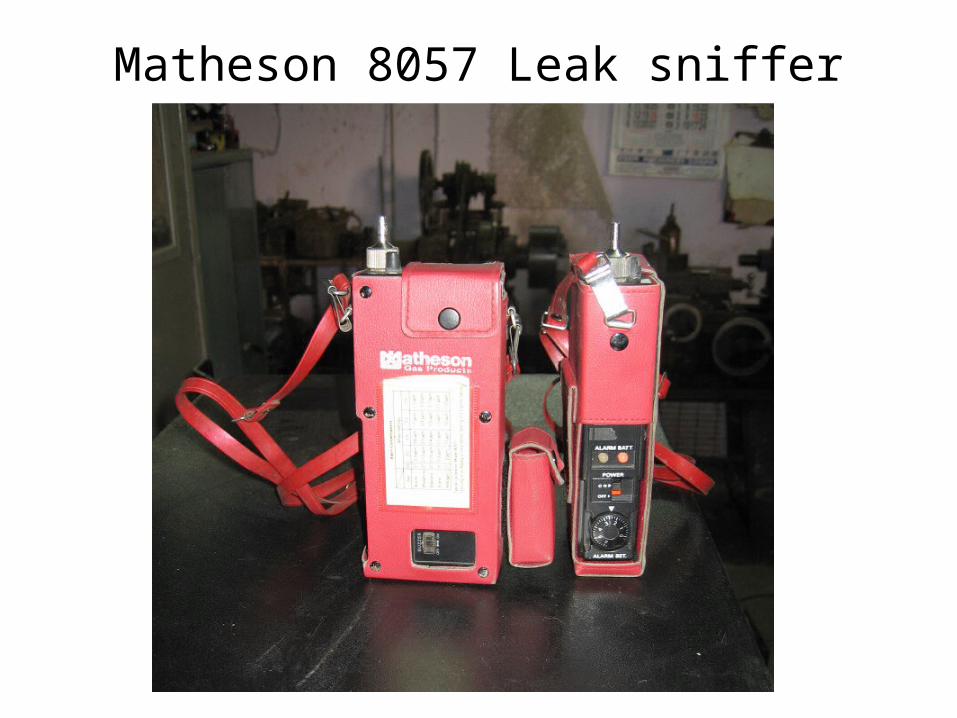
Matheson 8057 Leak sniffer

Automated Leak Test Bench for RPCs
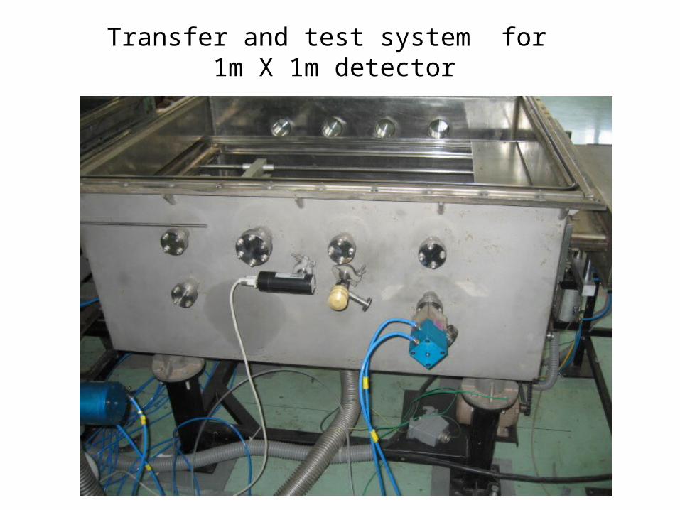
Transfer and test system for 1m X 1m detector
Acknowledgements
Prof. Aniruddha Pandit and Prof Gaikar Dept. of Chemical Engineering ICT Mumbai , India for CFD modeling of velocity distribution in RPCs