quality assurance programme for screen-film mammography
TRANSCRIPT

No. 2
Quality Assurance Programme for Screen Film Mammography
IAEA HumAN HEAltH SErIES
INTERNATIONAL ATOMIC ENERGY AGENCYVIENNA
ISBN 978–92–0–101609–6ISSN 2075-3772
This manual is intended to provide a standardized framework for quality control (QC) for mammography which can be used in Member States. It is intended to provide practical tests, using the simplest test equipment possible, to help ensure high quality screen film mammography. In order to maximize the benefit to those undergoing mammography where resources may be limited, this framework is supplemented with additional instructional material including a detailed section on clinical image quality.
IAEA HumAN HEAltH SErIES
Atoms for Peace
Atoms for Peace
Quality A
ssurance Program
me for Screen Film
Mam
mography
IAEA HumAN HEAltH SErIES No. 2
09_07231_P1381_cover.indd 1 2009-11-18 13:58:15

IAEA HUMAN HEALTH SERIES PUBLICATIONS
The mandate of the IAEA human health programme originates from Article II of its Statute, which states that the “Agency shall seek to accelerate and enlarge the contribution of atomic energy to peace, health and prosperity throughout the world”. The main objective of the human health programme is to enhance the capabilities of IAEA Member States in addressing issues related to the prevention, diagnosis and treatment of health problems through the development and application of nuclear techniques, within a framework of quality assurance.
Publications in the IAEA Human Health Series provide information in the areas of: radiation medicine, including diagnostic radiology, diagnostic and therapeutic nuclear medicine, and radiation therapy; dosimetry and medical radiation physics; and stable isotope techniques and other nuclear applications in nutrition. The publications have a broad readership and are aimed at medical practitioners, researchers and other professionals. International experts assist the IAEA Secretariat in drafting and reviewing these publications. Some of the publications in this series may also be endorsed or co-sponsored by international organizations and professional societies active in the relevant fields. There are two categories of publications in this series:
IAEA HUMAN HEALTH SERIESPublications in this category present analyses or provide information of an
advisory nature, for example guidelines, codes and standards of practice, and quality assurance manuals. Monographs and high level educational material, such as graduate texts, are also published in this series.
IAEA HUMAN HEALTH REPORTSHuman Health Reports complement information published in the IAEA Human
Health Series in areas of radiation medicine, dosimetry and medical radiation physics, and nutrition. These publications include reports of technical meetings, the results of IAEA coordinated research projects, interim reports on IAEA projects, and educational material compiled for IAEA training courses dealing with human health related subjects. In some cases, these reports may provide supporting material relating to publications issued in the IAEA Human Health Series.
All of these publications can be downloaded cost free from the IAEA web site:http://www.iaea.org/Publications/index.html
Further information is available from:Sales and Distribution UnitInternational Atomic Energy AgencyVienna International CentrePO Box 1001400 Vienna, Austria
Readers are invited to provide their impressions on these publications. Information may be provided via the IAEA web site, by mail at the address given above, or by email to:
09_07231_P1381_cover.indd 2 2009-11-18 13:58:15

QUALITY ASSURANCE PROGRAMMEFOR SCREEN FILM MAMMOGRAPHY

The following States are Members of the International Atomic Energy Agency:
AFGHANISTANALBANIAALGERIAANGOLAARGENTINAARMENIAAUSTRALIAAUSTRIAAZERBAIJANBAHRAINBANGLADESHBELARUSBELGIUMBELIZEBENINBOLIVIABOSNIA AND HERZEGOVINABOTSWANABRAZILBULGARIABURKINA FASOBURUNDICAMEROONCANADACENTRAL AFRICAN REPUBLICCHADCHILECHINACOLOMBIACONGOCOSTA RICACÔTE D’IVOIRECROATIACUBACYPRUSCZECH REPUBLICDEMOCRATIC REPUBLIC OF THE CONGODENMARKDOMINICAN REPUBLICECUADOREGYPTEL SALVADORERITREAESTONIAETHIOPIAFINLANDFRANCEGABONGEORGIAGERMANY
GHANAGREECEGUATEMALAHAITIHOLY SEEHONDURASHUNGARYICELANDINDIAINDONESIAIRAN, ISLAMIC REPUBLIC OF IRAQIRELANDISRAELITALYJAMAICAJAPANJORDANKAZAKHSTANKENYAKOREA, REPUBLIC OFKUWAITKYRGYZSTANLATVIALEBANONLESOTHOLIBERIALIBYAN ARAB JAMAHIRIYALIECHTENSTEINLITHUANIALUXEMBOURGMADAGASCARMALAWIMALAYSIAMALIMALTAMARSHALL ISLANDSMAURITANIAMAURITIUSMEXICOMONACOMONGOLIAMONTENEGROMOROCCOMOZAMBIQUEMYANMARNAMIBIANEPALNETHERLANDSNEW ZEALANDNICARAGUANIGER
NIGERIANORWAYOMANPAKISTANPALAUPANAMAPARAGUAYPERUPHILIPPINESPOLANDPORTUGALQATARREPUBLIC OF MOLDOVAROMANIARUSSIAN FEDERATIONSAUDI ARABIASENEGALSERBIASEYCHELLESSIERRA LEONESINGAPORESLOVAKIASLOVENIASOUTH AFRICASPAINSRI LANKASUDANSWEDENSWITZERLANDSYRIAN ARAB REPUBLICTAJIKISTANTHAILANDTHE FORMER YUGOSLAV REPUBLIC OF MACEDONIATUNISIATURKEYUGANDAUKRAINEUNITED ARAB EMIRATESUNITED KINGDOM OF GREAT BRITAIN AND NORTHERN IRELANDUNITED REPUBLIC OF TANZANIAUNITED STATES OF AMERICAURUGUAYUZBEKISTANVENEZUELAVIETNAMYEMENZAMBIAZIMBABWE
The Agency’s Statute was approved on 23 October 1956 by the Conference on the Statute of the IAEAheld at United Nations Headquarters, New York; it entered into force on 29 July 1957. The Headquarters of theAgency are situated in Vienna. Its principal objective is “to accelerate and enlarge the contribution of atomicenergy to peace, health and prosperity throughout the world’’.

QUALITY ASSURANCE PROGRAMME FORSCREEN FILM MAMMOGRAPHY
IAEA HUMAN HEALTH SERIES No. 2
INTERNATIONAL ATOMIC ENERGY AGENCYVIENNA, 2009

IAEA Library Cataloguing in Publication Data
Quality assurance programme for screen film mammography. — Vienna : International Atomic Energy Agency, 2009.
p. ; 2 cm. — (IAEA human health series, ISSN 2075–3772 ; no. 2)STI/PUB/1381ISBN 978–92–0–101609–6Includes bibliographical references.
1. Breast — Radiography — Quality control. 2. Breast — Cancer — Diagnosis — Quality control. I. International Atomic Energy Agency. II. Series.
IAEAL 09–00592
COPYRIGHT NOTICE
All IAEA scientific and technical publications are protected by the terms of the Universal Copyright Convention as adopted in 1952 (Berne) and as revised in 1972 (Paris). The copyright has since been extended by the World Intellectual Property Organization (Geneva) to include electronic and virtual intellectual property. Permission to use whole or parts of texts contained in IAEA publications in printed or electronic form must be obtained and is usually subject to royalty agreements. Proposals for non-commercial reproductions and translations are welcomed and considered on a case-by-case basis. Enquiries should be addressed to the IAEA Publishing Section at:
Sales and Promotion, Publishing SectionInternational Atomic Energy AgencyVienna International CentrePO Box 1001400 Vienna, Austriafax: +43 1 2600 29302tel.: +43 1 2600 22417email: [email protected] http://www.iaea.org/books
© IAEA, 2009
Printed by the IAEA in AustriaOctober 2009STI/PUB/1381
9
FOREWORD
The application of radiation in human health, for both the diagnosis and treatment of disease, is an important component of the work of the IAEA. In the area of diagnostic radiology, this work is focused on quality assurance methods to both the promotion of the effective use of radiation for diagnostic outcome, through achieving and maintaining appropriate image quality, and also on dose determination to allow the monitoring and reduction of dose to the patient.
In response to heightened awareness of the importance of patient dose contributed by radiology procedures, the IAEA published Dosimetry in Diagnostic Radiology: An International Code of Practice (Technical Reports Series No. 457) in 2007, to form a basis for patient dose determination for the Member States. Further to this, it is recognized that for complex diagnostic procedures, such as mammography, a detailed guidance document is required to give the professionals in the clinical centre the knowledge necessary to assess the patient dose, as well as to ensure that the procedure gives the maximal patient benefit possible. It is well documented that without the implementation of a quality culture and a systematic quality assurance programme with appropriate education, the detection of breast cancer cannot be made at an early enough stage to allow effective curative treatment to be undertaken.
Currently there are a number of established quality assurance protocols in mammography from national and regional institutions, however, many of these protocols are distinctive and so a harmonized approach is required. This will allow the Member States to facilitate quality assurance in mammography in a standardized way which will also facilitate the introduction of national quality assurance programmes that are needed to underpin effective population screening programmes for breast cancer.
Development of a quality assurance document for screen film mammography was started in 2005 with the appointment of a drafting committee of international experts. The current publication is endorsed by the European Federation of Organisations for Medical Physics and the Asia-Oceania Federation of Organizations of Medical Physics.
The IAEA acknowledges the special contribution of the drafting committee chaired by M. Yaffe (Canada), with M. Chevalier (Spain), J.C. Heggie (Australia), P. Mora (Costa Rica) and K. Young (United Kingdom), and the American College of Radiology (ACR), which gave permission for the use of material from its Quality Assurance Manual. PAHO involvement is also acknowledged. The IAEA officers responsible for this publication were I.D. McLean (Division of Human Health), F. Pernička (Division of Human Health) and P. Ortiz López (Division of Radiation, Transport and Waste Safety).

EDITORIAL NOTE
Although great care has been taken to maintain the accuracy of information contained in this publication, neither the IAEA nor its Member States assume any responsibility for consequences which may arise from its use.
The use of particular designations of countries or territories does not imply any judgement by the publisher, the IAEA, as to the legal status of such countries or territories, of their authorities and institutions or of the delimitation of their boundaries.
The mention of names of specific companies or products (whether or not indicated as registered) does not imply any intention to infringe proprietary rights, nor should it be construed as an endorsement or recommendation on the part of the IAEA.
CONTENTS
1. INTRODUCTION . . . . . . . . . . . . . . . . . . . . . . . . . . . . . . . . . . . . . . . . . . . . . . . . . . . . . . . . . . . . . . . . . . . . . 1
1.1. Why high quality in mammography is necessary . . . . . . . . . . . . . . . . . . . . . . . . . . . . . . . . . . . . . . . . 11.2. Purpose . . . . . . . . . . . . . . . . . . . . . . . . . . . . . . . . . . . . . . . . . . . . . . . . . . . . . . . . . . . . . . . . . . . . . . . . . . 11.3. Philosophy . . . . . . . . . . . . . . . . . . . . . . . . . . . . . . . . . . . . . . . . . . . . . . . . . . . . . . . . . . . . . . . . . . . . . . . 2
2. ELEMENTS OF HIGH QUALITY MAMMOGRAPHY . . . . . . . . . . . . . . . . . . . . . . . . . . . . . . . . . . . 3
2.1. Personnel . . . . . . . . . . . . . . . . . . . . . . . . . . . . . . . . . . . . . . . . . . . . . . . . . . . . . . . . . . . . . . . . . . . . . . . . 32.2. Equipment . . . . . . . . . . . . . . . . . . . . . . . . . . . . . . . . . . . . . . . . . . . . . . . . . . . . . . . . . . . . . . . . . . . . . . . 3
2.2.1. Mammography unit . . . . . . . . . . . . . . . . . . . . . . . . . . . . . . . . . . . . . . . . . . . . . . . . . . . . . . . . . 32.2.2. Image receptor system . . . . . . . . . . . . . . . . . . . . . . . . . . . . . . . . . . . . . . . . . . . . . . . . . . . . . . . 32.2.3. Processing . . . . . . . . . . . . . . . . . . . . . . . . . . . . . . . . . . . . . . . . . . . . . . . . . . . . . . . . . . . . . . . . . . 42.2.4. Viewing conditions . . . . . . . . . . . . . . . . . . . . . . . . . . . . . . . . . . . . . . . . . . . . . . . . . . . . . . . . . . 42.2.5. Quality assurance . . . . . . . . . . . . . . . . . . . . . . . . . . . . . . . . . . . . . . . . . . . . . . . . . . . . . . . . . . . 42.2.6. Regular maintenance. . . . . . . . . . . . . . . . . . . . . . . . . . . . . . . . . . . . . . . . . . . . . . . . . . . . . . . . . 4
3. BASIC PRINCIPLES OF QUALITY ASSURANCE IN MAMMOGRAPHY . . . . . . . . . . . . . . . . . 5
3.1. Quality assurance activities . . . . . . . . . . . . . . . . . . . . . . . . . . . . . . . . . . . . . . . . . . . . . . . . . . . . . . . . . 53.2. Roles and responsibilities . . . . . . . . . . . . . . . . . . . . . . . . . . . . . . . . . . . . . . . . . . . . . . . . . . . . . . . . . . . 7
3.2.1. The owner . . . . . . . . . . . . . . . . . . . . . . . . . . . . . . . . . . . . . . . . . . . . . . . . . . . . . . . . . . . . . . . . . 73.2.2. Lead interpreting physician (radiologist) . . . . . . . . . . . . . . . . . . . . . . . . . . . . . . . . . . . . . . . . 73.2.3. Radiographer (technologist) . . . . . . . . . . . . . . . . . . . . . . . . . . . . . . . . . . . . . . . . . . . . . . . . . . 73.2.4. Medical physicist . . . . . . . . . . . . . . . . . . . . . . . . . . . . . . . . . . . . . . . . . . . . . . . . . . . . . . . . . . . . 8
4. CLINICAL IMAGE QUALITY . . . . . . . . . . . . . . . . . . . . . . . . . . . . . . . . . . . . . . . . . . . . . . . . . . . . . . . . . 9
4.1. Patient positioning and compression . . . . . . . . . . . . . . . . . . . . . . . . . . . . . . . . . . . . . . . . . . . . . . . . . . 94.1.1. Introduction . . . . . . . . . . . . . . . . . . . . . . . . . . . . . . . . . . . . . . . . . . . . . . . . . . . . . . . . . . . . . . . . 94.1.2. Labelling of mammograms . . . . . . . . . . . . . . . . . . . . . . . . . . . . . . . . . . . . . . . . . . . . . . . . . . . 114.1.3. Breast compression . . . . . . . . . . . . . . . . . . . . . . . . . . . . . . . . . . . . . . . . . . . . . . . . . . . . . . . . . . 164.1.4. Patient positioning . . . . . . . . . . . . . . . . . . . . . . . . . . . . . . . . . . . . . . . . . . . . . . . . . . . . . . . . . . 184.1.5. Additional views . . . . . . . . . . . . . . . . . . . . . . . . . . . . . . . . . . . . . . . . . . . . . . . . . . . . . . . . . . . . 354.1.6. Special circumstances . . . . . . . . . . . . . . . . . . . . . . . . . . . . . . . . . . . . . . . . . . . . . . . . . . . . . . . . 524.1.7. Post-mastectomy imaging . . . . . . . . . . . . . . . . . . . . . . . . . . . . . . . . . . . . . . . . . . . . . . . . . . . . . 59
4.2. Clinical image evaluation . . . . . . . . . . . . . . . . . . . . . . . . . . . . . . . . . . . . . . . . . . . . . . . . . . . . . . . . . . . 594.2.1. Introduction . . . . . . . . . . . . . . . . . . . . . . . . . . . . . . . . . . . . . . . . . . . . . . . . . . . . . . . . . . . . . . . . 594.2.2. Mediolateral oblique view positioning . . . . . . . . . . . . . . . . . . . . . . . . . . . . . . . . . . . . . . . . . . 604.2.3. Craniocaudal view positioning . . . . . . . . . . . . . . . . . . . . . . . . . . . . . . . . . . . . . . . . . . . . . . . . . 664.2.4. Compression . . . . . . . . . . . . . . . . . . . . . . . . . . . . . . . . . . . . . . . . . . . . . . . . . . . . . . . . . . . . . . . 704.2.5. Exposure . . . . . . . . . . . . . . . . . . . . . . . . . . . . . . . . . . . . . . . . . . . . . . . . . . . . . . . . . . . . . . . . . . 724.2.6. Contrast . . . . . . . . . . . . . . . . . . . . . . . . . . . . . . . . . . . . . . . . . . . . . . . . . . . . . . . . . . . . . . . . . . . 774.2.7. Sharpness . . . . . . . . . . . . . . . . . . . . . . . . . . . . . . . . . . . . . . . . . . . . . . . . . . . . . . . . . . . . . . . . . . 794.2.8. Noise . . . . . . . . . . . . . . . . . . . . . . . . . . . . . . . . . . . . . . . . . . . . . . . . . . . . . . . . . . . . . . . . . . . . . . 814.2.9. Artefacts . . . . . . . . . . . . . . . . . . . . . . . . . . . . . . . . . . . . . . . . . . . . . . . . . . . . . . . . . . . . . . . . . . . 824.2.10. Collimation . . . . . . . . . . . . . . . . . . . . . . . . . . . . . . . . . . . . . . . . . . . . . . . . . . . . . . . . . . . . . . . . 854.2.11. Labelling . . . . . . . . . . . . . . . . . . . . . . . . . . . . . . . . . . . . . . . . . . . . . . . . . . . . . . . . . . . . . . . . . . . 854.2.12. Conclusion . . . . . . . . . . . . . . . . . . . . . . . . . . . . . . . . . . . . . . . . . . . . . . . . . . . . . . . . . . . . . . . . . 86
Bibliography to Chapter 4 . . . . . . . . . . . . . . . . . . . . . . . . . . . . . . . . . . . . . . . . . . . . . . . . . . . . . . . . . . . . . . . 87

5. OUTLINE OF QC TESTS . . . . . . . . . . . . . . . . . . . . . . . . . . . . . . . . . . . . . . . . . . . . . . . . . . . . . . . . . . . . . . 89
6. RADIOGRAPHER’S QUALITY CONTROL TESTS . . . . . . . . . . . . . . . . . . . . . . . . . . . . . . . . . . . . . . 91
6.1. Visual inspection . . . . . . . . . . . . . . . . . . . . . . . . . . . . . . . . . . . . . . . . . . . . . . . . . . . . . . . . . . . . . . . . . . 936.1.1. Radiological equipment . . . . . . . . . . . . . . . . . . . . . . . . . . . . . . . . . . . . . . . . . . . . . . . . . . . . . . 93
6.2. Film storage . . . . . . . . . . . . . . . . . . . . . . . . . . . . . . . . . . . . . . . . . . . . . . . . . . . . . . . . . . . . . . . . . . . . . . 946.2.1. Temperature and humidity . . . . . . . . . . . . . . . . . . . . . . . . . . . . . . . . . . . . . . . . . . . . . . . . . . . . 94
6.3. Darkroom and film processing . . . . . . . . . . . . . . . . . . . . . . . . . . . . . . . . . . . . . . . . . . . . . . . . . . . . . . . 956.3.1. Darkroom cleanliness . . . . . . . . . . . . . . . . . . . . . . . . . . . . . . . . . . . . . . . . . . . . . . . . . . . . . . . . 956.3.2. Evaluation of temperature, humidity and ventilation conditions . . . . . . . . . . . . . . . . . . . . 966.3.3. White light leakage and safe lights . . . . . . . . . . . . . . . . . . . . . . . . . . . . . . . . . . . . . . . . . . . . . 976.3.4. Automatic processor developer temperature and other parameters . . . . . . . . . . . . . . . . . 996.3.5. Sensitometry . . . . . . . . . . . . . . . . . . . . . . . . . . . . . . . . . . . . . . . . . . . . . . . . . . . . . . . . . . . . . . . 1006.3.6. Artefact detection . . . . . . . . . . . . . . . . . . . . . . . . . . . . . . . . . . . . . . . . . . . . . . . . . . . . . . . . . . . 1046.3.7. Transition between film emulsion numbers . . . . . . . . . . . . . . . . . . . . . . . . . . . . . . . . . . . . . . 105
6.4. Imaging system . . . . . . . . . . . . . . . . . . . . . . . . . . . . . . . . . . . . . . . . . . . . . . . . . . . . . . . . . . . . . . . . . . . . 1066.4.1. Cleaning of intensifying screens . . . . . . . . . . . . . . . . . . . . . . . . . . . . . . . . . . . . . . . . . . . . . . . 1066.4.2. Screen film contact and light tightness of cassettes . . . . . . . . . . . . . . . . . . . . . . . . . . . . . . . 1076.4.3. Uniformity of cassette sensitivity, attenuation and artefacts . . . . . . . . . . . . . . . . . . . . . . . . 109
6.5. Automatic exposure control . . . . . . . . . . . . . . . . . . . . . . . . . . . . . . . . . . . . . . . . . . . . . . . . . . . . . . . . . 1116.5.1. Test of system constancy . . . . . . . . . . . . . . . . . . . . . . . . . . . . . . . . . . . . . . . . . . . . . . . . . . . . . . 1116.5.2. Test of AEC thickness compensation . . . . . . . . . . . . . . . . . . . . . . . . . . . . . . . . . . . . . . . . . . . 114
6.6. Image quality . . . . . . . . . . . . . . . . . . . . . . . . . . . . . . . . . . . . . . . . . . . . . . . . . . . . . . . . . . . . . . . . . . . . . 1166.6.1. Evaluation of image quality . . . . . . . . . . . . . . . . . . . . . . . . . . . . . . . . . . . . . . . . . . . . . . . . . . . 116
6.7. Film rejection rate . . . . . . . . . . . . . . . . . . . . . . . . . . . . . . . . . . . . . . . . . . . . . . . . . . . . . . . . . . . . . . . . . 1186.7.1. Film rejection rate . . . . . . . . . . . . . . . . . . . . . . . . . . . . . . . . . . . . . . . . . . . . . . . . . . . . . . . . . . . 118
7. MEDICAL PHYSICIST’S TESTS . . . . . . . . . . . . . . . . . . . . . . . . . . . . . . . . . . . . . . . . . . . . . . . . . . . . . . . . 119
7.1. Unit assembly . . . . . . . . . . . . . . . . . . . . . . . . . . . . . . . . . . . . . . . . . . . . . . . . . . . . . . . . . . . . . . . . . . . . . 1217.1.1. Unit assembly evaluation . . . . . . . . . . . . . . . . . . . . . . . . . . . . . . . . . . . . . . . . . . . . . . . . . . . . . 121
7.2. Sensitometry and darkroom . . . . . . . . . . . . . . . . . . . . . . . . . . . . . . . . . . . . . . . . . . . . . . . . . . . . . . . . 1227.2.1. Sensitometry and darkroom conditions . . . . . . . . . . . . . . . . . . . . . . . . . . . . . . . . . . . . . . . . . 122
7.3. Radiological equipment . . . . . . . . . . . . . . . . . . . . . . . . . . . . . . . . . . . . . . . . . . . . . . . . . . . . . . . . . . . . 1237.3.1. Radiation leakage . . . . . . . . . . . . . . . . . . . . . . . . . . . . . . . . . . . . . . . . . . . . . . . . . . . . . . . . . . . 1237.3.2. Accuracy and repeatability of kVp . . . . . . . . . . . . . . . . . . . . . . . . . . . . . . . . . . . . . . . . . . . . . 1257.3.3. Half-value layer (HVL) . . . . . . . . . . . . . . . . . . . . . . . . . . . . . . . . . . . . . . . . . . . . . . . . . . . . . . 1277.3.4. Output repeatability and linearity . . . . . . . . . . . . . . . . . . . . . . . . . . . . . . . . . . . . . . . . . . . . . 1297.3.5. Compression . . . . . . . . . . . . . . . . . . . . . . . . . . . . . . . . . . . . . . . . . . . . . . . . . . . . . . . . . . . . . . . 1317.3.6. Evaluation of the automatic exposure control . . . . . . . . . . . . . . . . . . . . . . . . . . . . . . . . . . . 133
7.4. Collimation system . . . . . . . . . . . . . . . . . . . . . . . . . . . . . . . . . . . . . . . . . . . . . . . . . . . . . . . . . . . . . . . . 1367.4.1. Collimation system . . . . . . . . . . . . . . . . . . . . . . . . . . . . . . . . . . . . . . . . . . . . . . . . . . . . . . . . . . 136
7.5. Image viewing conditions . . . . . . . . . . . . . . . . . . . . . . . . . . . . . . . . . . . . . . . . . . . . . . . . . . . . . . . . . . . 1387.5.1. Luminance and homogeneity of the viewboxes . . . . . . . . . . . . . . . . . . . . . . . . . . . . . . . . . . 1387.5.2. Interpretation room ambient illumination . . . . . . . . . . . . . . . . . . . . . . . . . . . . . . . . . . . . . . . 140
7.6. Image quality . . . . . . . . . . . . . . . . . . . . . . . . . . . . . . . . . . . . . . . . . . . . . . . . . . . . . . . . . . . . . . . . . . . . . 1417.6.1. Evaluation of image quality . . . . . . . . . . . . . . . . . . . . . . . . . . . . . . . . . . . . . . . . . . . . . . . . . . . 1417.6.2. System spatial resolution . . . . . . . . . . . . . . . . . . . . . . . . . . . . . . . . . . . . . . . . . . . . . . . . . . . . . 144
7.7. Dosimetry . . . . . . . . . . . . . . . . . . . . . . . . . . . . . . . . . . . . . . . . . . . . . . . . . . . . . . . . . . . . . . . . . . . . . . . . 1457.7.1. Incident air kerma at the entrance surface of the phantom . . . . . . . . . . . . . . . . . . . . . . . . . 1457.7.2. Determination of the mean glandular dose (DG) . . . . . . . . . . . . . . . . . . . . . . . . . . . . . . . . . 148

APPENDIX I: GUIDELINES FOR THE TRAINING OF A MEDICAL PHYSICISTSPECIALIZING IN MAMMOGRAPHY . . . . . . . . . . . . . . . . . . . . . . . . . . . . . . . . . . . . . 151
APPENDIX II: MAMMOGRAPHY ROOM DESIGN . . . . . . . . . . . . . . . . . . . . . . . . . . . . . . . . . . . . . . . 152APPENDIX III: DARKROOM DESIGN . . . . . . . . . . . . . . . . . . . . . . . . . . . . . . . . . . . . . . . . . . . . . . . . . . . . 155APPENDIX IV: TEST EQUIPMENT SPECIFICATIONS . . . . . . . . . . . . . . . . . . . . . . . . . . . . . . . . . . . . . 160APPENDIX V: AUTOMATIC PROCESSOR DEVELOPER TIME, SPECIFIC GRAVITY,
REPLENISHMENT AND pH . . . . . . . . . . . . . . . . . . . . . . . . . . . . . . . . . . . . . . . . . . . . . . . 161APPENDIX VI: EXAMPLE OF A CALCULATION FOR FILM CROSSOVER PROCEDURE . . . 163APPENDIX VII: CALCULATION OF AVERAGE FILM GRADIENT . . . . . . . . . . . . . . . . . . . . . . . . . 164APPENDIX VIII: THE STANDARD BREAST . . . . . . . . . . . . . . . . . . . . . . . . . . . . . . . . . . . . . . . . . . . . . . . 166
REFERENCES . . . . . . . . . . . . . . . . . . . . . . . . . . . . . . . . . . . . . . . . . . . . . . . . . . . . . . . . . . . . . . . . . . . . . . . . . . . . 167BIBLIOGRAPHY . . . . . . . . . . . . . . . . . . . . . . . . . . . . . . . . . . . . . . . . . . . . . . . . . . . . . . . . . . . . . . . . . . . . . . . . . . 169
ANNEX I: RADIOGRAPHER’S DATA COLLECTION SHEETS . . . . . . . . . . . . . . . . . . . . . . . . . . . . . . 171ANNEX II: MEDICAL PHYSICIST’S DATA COLLECTION SHEETS . . . . . . . . . . . . . . . . . . . . . . . . . . 195
GLOSSARY . . . . . . . . . . . . . . . . . . . . . . . . . . . . . . . . . . . . . . . . . . . . . . . . . . . . . . . . . . . . . . . . . . . . . . . . . . . . . . . 217CONTRIBUTORS TO DRAFTING AND REVIEW . . . . . . . . . . . . . . . . . . . . . . . . . . . . . . . . . . . . . . . . . . . 221

1. INTRODUCTION
1.1. WHY HIGH QUALITY IN MAMMOGRAPHY IS NECESSARY
Breast cancer is the most common cancer among women worldwide and is a leading cause of cancer mortality in women. Breast cancer incidence increased 30–40% from the 1970s to the 1990s in most countries, with the most marked increases among women aged 50 years and older, although the incidence for women under 50 years is increasing. Overall, North American and northern European countries have the highest incidence rates of breast cancer; intermediate levels have been reported in western Europe, Oceania, Scandinavia and Israel; the lowest levels are observed in eastern Europe, Central America and South America, and Asia. Breast cancer incidence and mortality rates vary fourfold by geographic location between countries with the highest and lowest rates.
Mammography is an X ray examination of the breast. Its principal purpose is to facilitate the detection of breast cancer at a point earlier in its natural history than is possible by clinical examination. It has been demonstrated that routine screening with high quality mammography is effective in reducing mortality from breast cancer in women aged 40–69 years [1, 2]. In countries with such mammography screening programmes, there has been a marked decrease in breast cancer mortality over the past two decades [2]. Mammography is also useful in refining the diagnosis of breast cancer (assessment or workup) after a suspicious area in the breast has been detected and for localizing a lesion for therapy.
The radiological signs of breast cancer include mass densities which are typically slightly more attenuating of X rays than the surrounding normal tissue, small microcalcifications, asymmetry between the two breasts and architectural distortion of tissue patterns. In order to detect breast cancer accurately and at the earliest possible stage, the image must have excellent contrast to reveal mass densities and spiculated fibrous structures radiating from them that are characteristic of cancer. In addition, the spatial resolution must be excellent to reveal the calcifications, their number and their shape. The imaging system must have adequate latitude to provide this contrast and resolution over the entire breast effectively. The geometrical characteristics of the X ray unit and the positioning of the breast by the radiographer must be such that as much breast tissue as possible is included in the mammogram. Finally, the noise (signal fluctuation) of the image must be sufficiently low to reveal the subtle structures in a reliable manner and the X ray dose must be as low as reasonably achievable while being compatible with these image quality requirements.
1.2. PURPOSE
It has been well established that to achieve high quality mammography, the following elements are essential:
(1) Well trained and experienced personnel (radiologist, radiographer, medical physicist);(2) Modern, well designed equipment;(3) Equipment in good working order;(4) Proper positioning and technical factors for exposure;(5) Appropriate image viewing conditions.
An effective quality assurance (QA) programme is necessary to ensure that all of these elements remain in place over time. The part of this programme that is concerned with the technical aspects is referred to as quality control (QC).
This publication is intended to provide a standardized framework for QC for mammography which can be used in Member States. It is intended to provide practical tests to help ensure high quality of screen film mammography. In order to be feasible in areas where resources may be limited, the tests are designed to be carried out with the simplest test equipment possible.
1
1.3. PHILOSOPHY
Several well established QC programmes for mammography currently exist in different jurisdictions [3, 4]. These are comprehensive and reflect resources available in those countries. The IAEA recognizes the different resources and needs of Member States and has developed specific programmes for individual areas. An example is a QC programme for mammography developed for the Latin American countries, implemented in the framework of the Regional Cooperative Agreement for the Advancement of Nuclear Science and Technology in Latin America and the Caribbean (known as ARCAL) [5] and associated national protocols [6]. The present report attempts to incorporate the most important components of these programmes in a harmonized manner to be useful to the broad range of Member States. It has been developed with the philosophy that if mammography is to be performed, it must be of high quality in order to allow the earliest detection of cancers. In some areas, both human and technological resources are limited and, therefore, this publication was developed with the concept of practicality in mind.
Recent publications indicate that digital mammography can provide equal or superior accuracy to screen film mammography [7]. Digital mammography also has potential for increased efficiency in image archiving and retrieval and the possibility to avoid the costs, complexity and waste disposal problems associated with chemical processing of film. These factors have stimulated interest in the acquisition of digital systems. This presents both opportunities and challenges to those involved in delivering mammography services. Like screen film mammography, it is apparent that the clinical performance of digital mammography depends on the proper design of the equipment and its use in an optimized manner. Therefore, one of the important challenges is to have in place in a timely fashion an appropriate framework of QA for digital mammography systems. The present publication addresses only QA issues relevant to screen film mammography. It is intended that an additional publication will address the specific issues associated with the use of digital mammography.
2
2. ELEMENTS OF HIGH QUALITY MAMMOGRAPHY
2.1. PERSONNEL
There are many elements that contribute to the mammography process. The experience of personnel directly and indirectly involved in the mammographic task is crucial to the final outcome. In that respect, it is essential that:
— The mammography images be acquired by experienced radiographers trained specifically in mammography (see Section 4.1, for example, on the importance of correct positioning and the use of compression);
— The images be interpreted by an appropriately trained and experienced radiologist;— A medical physicist be available as a consultant to the facility. This may be either on a full time or part time
basis, according to the needs of the facility in QA and radiation protection. (See Section 3.2.4 and Appendix I for the specific requirements that a medical physicist should meet.) The availability and qualifications of the medical physicist must be in compliance with local regulations.
2.2. EQUIPMENT
2.2.1. Mammography unit
The X ray unit must be specifically designed for mammography and include the following key features:
— X ray tube with a nominal focal spot of 0.3 mm [8];— If magnification mammography is performed (this capability should be present on systems that are used
for diagnostic mammography and not exclusively for screening), a magnification stand and a second, smaller focal spot of nominal size 0.15 mm;
— Molybdenum target. Supplementary targets composed of materials such as tungsten or rhodium may also be available;
— Tube current 80 mA for a Mo target for contact mammography and 20 mA for magnification mammography;
— Beryllium exit window;— Beam filter of molybdenum. An additional filter composed of rhodium is highly desirable;— Motorized compression device;— Readout of compression thickness and force is highly desirable;— Automatic exposure control (AEC) with a sensor whose position is adjustable;— Fine control of optical density on AEC;— Moving grid designed for mammography;— Focus–film distance 60 cm;— Buckys that can accommodate film of sizes 18 cm × 24 cm and 24 cm × 30 cm are desirable.
The room in which the mammography unit is sited should have a stable temperature and humidity for satisfactory operation. This may require appropriate air conditioning. More complete details for siting a mammography unit are provided in Appendix II.
2.2.2. Image receptor system
An acceptable image receptor system is characterized by having:
— Cassettes designed for mammography;— A high resolution single mammography screen in cassette;— Appropriate mammography film matched to be used with the selected screen.
3

2.2.3. Processing
Acceptable film processing requires:
— Automatic processor with digital readout of developer temperature.— Appropriate replenishment system for mammography, matched to the film volume processed at the
facility.— Use of processing chemicals matched to the film that is used.— Correct processing time, temperature and replenishment setting.— Proper water quality and temperature control.— If a darkroom is used, it must be free of light leaks and internal light sources that could fog the film. The
level of ionizing radiation in the darkroom must also be within acceptable tolerances.— Darkroom, cassettes and screens must be free from dust that could cause artefacts in the mammograms.— Proper ventilation of processing area.— Appropriate storage of films and chemicals.— Management of film and chemical inventory to ensure that fresh materials are used for imaging.
See Appendix III for more details on some of the requirements mentioned.
2.2.4. Viewing conditions
Successful viewing conditions require:
— A viewbox designed for mammography with luminance 3000 cd/m2;— Lamps in the viewbox matched for brightness and colour;— The ability to mask edges of mammograms;— Low ambient light in the room.
2.2.5. Quality assurance
To ensure high quality, all of the above factors are necessary; however, in addition, it is essential that a comprehensive QA programme be in place. It is also imperative that time be allocated to allow the necessary QC tests to be performed regularly, that results be carefully recorded and that corrective action be taken promptly when indicated. The basic elements of a QA programme in mammography are outlined in Section 3.
2.2.6. Regular maintenance
In addition to regular quality assurance, it is also essential that all mammographic units and associated film processors undergo regular maintenance consistent with best practice or recommendations from the manufacturers.
4
3. BASIC PRINCIPLES OF QUALITY ASSURANCEIN MAMMOGRAPHY
3.1. QUALITY ASSURANCE ACTIVITIES
A QA programme in diagnostic radiology, as defined by WHO [9], is an organized effort by the staff operating a facility to ensure that the diagnostic images produced are of sufficiently high quality so that they consistently provide adequate diagnostic information at the lowest possible cost and with the least possible exposure of the patient to radiation. Registrants and licensees shall establish a comprehensive QA programme for medical diagnosis with the participation of appropriate medical physicists, taking into account the principles established by WHO [9].
QA programmes for medical exposures shall include:
(1) Measurements of the physical parameters of the radiation generators and imaging devices at the time of commissioning and periodically thereafter.
(2) Verification of the appropriate physical and clinical factors used in patient diagnosis (or treatment).(3) Written records of relevant procedures and results. This includes a manual that defines clear lines of
responsibility, outlines the individual QC tests performed, gives the test frequencies, is useful for staff training, facilitates audit of a service and helps to keep information within the service.
(4) Verification of the appropriate calibration and conditions of operation of the dosimetry and monitoring equipment.
(5) Optimization of clinical protocols and equipment operation to achieve the aims of QA as stated previously.(6) Regular and independent quality audit reviews of the QA programme.
QA programmes are designed to ensure that the radiology equipment and staff procedures yield the desired information. They include:
(1) Administrative procedures or management actions designed to verify that:— QC tests are performed properly and according to a planned timetable; — Results of these tests are evaluated promptly and accurately; — The necessary corrective measures are taken in response to these results;— There is an appropriate assignment of responsibility for QA actions;— Standards of quality are established for equipment in the facility;— Adequate training is provided; — Appropriate equipment for each examination is selected, including the writing of adequate equipment
specifications.(2) Acceptance testing and commissioning (see Fig. 1):
— Acceptance tests are those performed to verify that the purchase specifications have been met by the vendor. These tests are often performed by the company installing the equipment, under the supervision of the medical physicist [10] or, preferably, independently by the medical physicist.
— Commissioning tests are those undertaken at the time the equipment is put into service; they are used to establish baseline levels of performance and are performed by the medical physicist.
— To a large extent, these tests overlap. This publication primarily describes tests that form a comprehensive, ongoing QC programme for mammography, but it is recognized that it is necessary to ensure that the equipment as delivered conforms to specified standards and that appropriate initial baseline values are established and used to ensure the maintenance for the quality of the equipment throughout its service life. These acceptance and commissioning tests are included in this publication and are indicated as such. During acceptance testing, a qualified person should check the electrical and mechanical safety of any new installation.
5

(3) QC tests (also classified as either constancy or status tests by the IEC) are used to test the components of the radiological system and verify that the equipment is operating satisfactorily.
(4) Verification of QC equipment and material.(5) Follow-up of any corrective actions proposed:
— It is important that routine QC testing be properly performed in the mammography facility and that results be documented thoroughly and carefully. It is equally important that problems and potential problems be clearly documented and communicated to the facility in a timely manner and that the medical physicist be assured that the receiving party has received and understood the supplied information. This is especially the case when safety concerns are raised.
— The reporting structure in the facility should be understood by the medical physicist, who should ideally report problems to an individual who is empowered to call in service personnel and, if necessary, who can ensure that the equipment is not used until the problems are corrected. The medical physicist may be asked to explain the problems to service personnel and share test results with them. The medical physicist and the representative from the facility should work together to ensure that the problems have been appropriately corrected.
(6) Education and training of staff, including the radiologist, radiographer and medical physicist: each must meet a minimum level of qualification.
(7) Continuing education: Each team member must undertake sufficient continuing education to ensure that they are up to date on new techniques and that they are refreshed relative to their basic knowledge, for example, of radiation safety.
(8) Experience: To ensure proficiency on an annual basis, the radiologist must read a sufficient number of cases; the radiographer must do a minimum number of cases; and the medical physicist must perform a sufficient number of acceptance tests and carry out routine QC testing on a sufficient number of mammography units.
Replacement
Tender
Equipment
specification
Purchase
contract
Installation
Disposal or
sale
Clinical use
Commissioning Critical examination on
behalf of installer Acceptance test on
behalf of purchaser
Routine performance
testing & maintenance Component
replacement
Critical
exam/commissioning
FIG. 1. Life cycle of a piece of equipment.
6

3.2. ROLES AND RESPONSIBILITIES
3.2.1. The owner
The owner has specific responsibilities to ensure that all regulatory and/or licensing requirements are met. Further, the owner must ensure that all radiologists, radiographers, medical physicists and other personnel who work at the facility are appropriately qualified and trained, and meet all continuing education and experience requirements.
It is the responsibility of the owner to ensure that a QA programme is in place encompassing all aspects of the mammography imaging process. The specific tasks within that programme may be delegated to appropriate staff who may have more expertise to carry out those tasks. Notwithstanding the above delegation, it remains the ultimate responsibility of the owner that the elements of the QA programme are fulfilled.
A lead interpreting physician (LIP), usually a mammography radiologist, should be identified by the mammography facility to have the specific responsibility of ensuring that all required QA activities are performed.
3.2.2. Lead interpreting physician (radiologist)
Although it is recognized that the LIP will delegate many of the following tasks, the LIP still has the responsibilities for:
(1) Ensuring that the technical personnel and/or radiographers have adequate training and continuous education courses in mammography.
(2) Motivating, supervising and managing all the aspects related to the QC programme in the area of mammography.
(3) Providing an orientation programme for radiographers based on a carefully established procedures manual.
(4) Selecting a single radiographer to be the primary QC radiographer to perform the prescribed QC tests and oversee those that have been delegated to other individuals.
(5) Ensuring the availability of the equipment and necessary materials for implementation of the QC tests. (6) Arranging staffing and scheduling so that adequate time is available to carry out the QC tests and to record
and interpret the results.(7) Ensuring that a medical physicist is available to oversee the equipment related QC programme and to
perform the medical physicist’s tests.(8) Reviewing the radiographer’s test results at least every three months, or more frequently if consistency has
not yet been achieved; and reviewing the medical physicist’s test results annually, or more frequently when needed.
(9) Overseeing, or designating an individual to oversee, the radiation protection programme for employees, patients and other individuals in the surrounding area.
(10) Ensuring that records concerning employee qualifications, mammography technique and procedures, infection control procedures, QC, safety and protection are properly maintained and updated.
(11) Providing feedback continually, both positive and negative, to the technical personnel and/or radiographers, on the image quality and the QC procedures.
(12) Verifying the percentage of rejected films performed by the radiographers and ensuring that if it exceeds the specified limit, appropriate corrective action is implemented.
3.2.3. Radiographer (technologist)
The responsibilities of the radiographer include:
(1) Ensuring that the QC tests are performed, interpreted and recorded appropriately. This is best achieved when one radiographer assumes overall responsibility for QC matters and is able to train others to assist in QC activities.
7

(2) Recording imaging problems.(3) Undertaking additional continuous education courses in mammography.
3.2.4. Medical physicist
The medical physicist is a person trained in medical physics and certified as a medical physicist according to the applicable programme in the Member State, if such a programme exists. Guidelines for the training of a medical physicist are given in Appendix I. If it is not possible to have a medical physicist carry out the specified medical physicist’s tests in this document, then such tests may be delegated to a trained radiographer or to a service person employed by the vendor of the mammography equipment.
The minimum requirements for an individual who is delegated to carry out the annual medical physicist’s QC tests described in this publication are:
(1) Training in radiation safety;(2) Training in the physics of mammography;(3) Practical training in the testing of mammography equipment.
The responsibilities of the medical physicist include:
(1) Advising the facility on the safe and effective use of X rays for mammography. This includes image quality and radiation protection of the patient and personnel.
(2) Advising the facility on equipment for mammography.(3) Conducting tests to ensure the safety and proper performance of equipment used in mammography. These
tests include acceptance, commissioning and routine QC tests.(4) Providing oversight and advice to the radiographer who carries out the radiographer’s component of the
QC programme.
8

9
4. CLINICAL IMAGE QUALITY
4.1. PATIENT POSITIONING AND COMPRESSION1
4.1.1. Introduction
Breast positioning is an art that has undergone significant changes recently. Incorrect positioning is the most common problem encountered when evaluating clinical images. When mammography and xeromammography were performed with conventional X ray equipment, positioning was limited to manoeuvres in which the patient was turned while lying on her side or seated directly under the overhead tube. With the evolution of dedicated equipment that allows rotation of the X ray tube, the possibilities for breast positioning became greater. Rather than relying on methods that were based on traditional radiographic projections (lateral and craniocaudal), the art of positioning has been refined by combining a better understanding of the breast’s anatomy and mobility with the greater versatility of modern dedicated equipment. In addition, it is now understood that breast positioning should be tailored to the patient’s specific habitus and breast problem. Today, the resourceful radiologist and radiographer can rely on a great variety of positioning techniques to improve breast cancer detection and facilitate the evaluation of breast abnormalities.
This section provides a guide to performing:
(1) Standard views for screening;(2) Views used to localize the exact position of an abnormality in the breast;(3) Views used to better define the nature of an abnormality.
Methods for performing mammograms under special circumstances, with challenging patients, for example, are also included. The views are named in accordance with new ACR recommendations for standardized mammographic terminology. Table 1 presents each of the views discussed in this section, along with its new recommended labelling code and its purpose.
1 The material in this chapter is drawn from the Mammography Quality Control Manual of the American College of Radiology (ACR), and is reprinted with permission of the ACR. No other representation of this material is authorized without expressed, written permission from the ACR. Some of the textual references, for example, are to the Mammography Quality Standards Act (MQSA) requirements in the USA, and do not have mandatory application to Member States. They are included as part of the agreement with the ACR to reproduce their text in full in this technical report.
For copyright reasons, the material in Chapter 4 is available in the hard copy version only of this publication.
5. OUTLINE OF QC TESTS
QC tests are intended to verify the stability in the operation of the equipment or elements used to acquire the mammogram. The tests have been classified into two types: essential and desirable, with respect to their importance in influencing image quality and dose. The performance of the first category of tests is considered indispensable; however, it is recommended that the tests in the second category be carried out if adequate human resources and equipment can be made available.
Many of the tests need to be performed very frequently (weekly and daily). Therefore, it is recommended that these tests be performed by local personnel who are present daily in the installation (technical personnel, normally radiographers). The lower frequency tests have been assigned in the majority of the cases to medical physicists and radiologists. Tolerance values for the tests are indicated. Again, these are classified into two categories: acceptable and achievable. In some cases, only the acceptable level has been defined.
A facility should strive to ensure that equipment operates at the achievable level of performance, as this will produce the highest image quality and the most appropriate dose performance. It is recognized, however, that limited resources and other factors may occasionally prevent the achievable levels from being obtained. In no case should the facility continue to perform mammography if the equipment does not meet the acceptable standard of operation, because below this level the value of the procedure and/or its safety is considered unacceptable. Each test in the QC programme has a specified tolerance level for achievable and acceptable results as applicable. Should the results of a test fall outside the specified tolerance, the test should usually be repeated to confirm the result before action is taken.
Suitable minimum specifications for test equipment are provided in Appendix IV.Table 2 in Chapter 6 and Table 4 in Chapter 7 list all the tests to be carried out by the radiographer and the
medical physicist, respectively. In some cases, either could perform a particular test, so the tests are listed in both tables. In such cases, a decision must be made as to who will actually do the test and that person should consistently do the test thereafter.
Test Priority
Essential refers to tests that must be done in a facility.Desirable describes the test procedures that should be performed if feasible.
Performance Standards
Acceptable indicates that performance must be within these tolerancesand if it is not, the equipment should not be used.
Achievable indicates the level of performance that should be attained under favourable circumstances;this is the level at which a facility should work if it is feasible.
89

.
6. RADIOGRAPHER’S QUALITY CONTROL TESTS
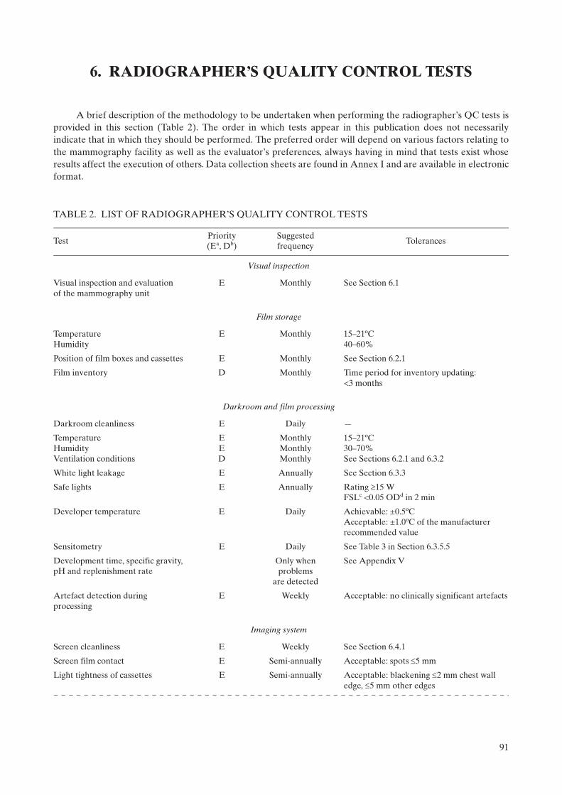
A brief description of the methodology to be undertaken when performing the radiographer’s QC tests is provided in this section (Table 2). The order in which tests appear in this publication does not necessarily indicate that in which they should be performed. The preferred order will depend on various factors relating to the mammography facility as well as the evaluator’s preferences, always having in mind that tests exist whose results affect the execution of others. Data collection sheets are found in Annex I and are available in electronic format.
TABLE 2. LIST OF RADIOGRAPHER’S QUALITY CONTROL TESTS
TestPriority (Ea, Db)
Suggested frequency
Tolerances
Visual inspection
Visual inspection and evaluationof the mammography unit
E Monthly See Section 6.1
Film storage
TemperatureHumidity
E Monthly 15–21ºC40–60%
Position of film boxes and cassettes E Monthly See Section 6.2.1
Film inventory D Monthly Time period for inventory updating:<3 months
Darkroom and film processing
Darkroom cleanliness E Daily —
TemperatureHumidityVentilation conditions
EED
MonthlyMonthlyMonthly
15–21ºC30–70%See Sections 6.2.1 and 6.3.2
White light leakage E Annually See Section 6.3.3
Safe lights E Annually Rating 15 W FSLc <0.05 ODd in 2 min
Developer temperature E Daily Achievable: ±0.5ºCAcceptable: ±1.0ºC of the manufacturer recommended value
Sensitometry E Daily See Table 3 in Section 6.3.5.5
Development time, specific gravity, pH and replenishment rate
Only when problems
are detected
See Appendix V
Artefact detection during processing
E Weekly Acceptable: no clinically significant artefacts
Imaging system
Screen cleanliness E Weekly See Section 6.4.1
Screen film contact E Semi-annually Acceptable: spots 5 mm
Light tightness of cassettes E Semi-annually Acceptable: blackening 2 mm chest wall edge, 5 mm other edges
91
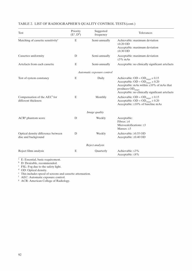
Matching of cassette sensitivitye E Semi-annually Achievable: maximum deviation0.20 OD Acceptable: maximum deviation0.30 OD
Cassettes uniformity D Semi-annually Acceptable: maximum deviation5% mAs
Artefacts from each cassette E Semi-annually Acceptable: no clinically significant artefacts
Automatic exposure control
Test of system constancy E Daily Achievable: OD = ODtarget ± 0.15 Acceptable: OD = ODtarget ± 0.20 Acceptable: mAs within ±10% of mAs that produces ODtarget
Acceptable: no clinically significant artefacts
Compensation of the AECf for different thickness
E Monthly Achievable: OD = ODtarget 0.15 Acceptable: OD = ODtarget 0.20Acceptable: 10% of baseline mAs
Image quality
ACRg phantom score D Weekly Acceptable: Fibres: 4 Microcalcifications: 3 Masses: 3
Optical density difference between disc and background
D Weekly Achievable: 0.55 ODAcceptable: 0.40 OD
Reject analysis
Reject films analysis E Quarterly Achievable: 3% Acceptable: 8%
a E: Essential, basic requirement. b D: Desirable, recommended. c FSL: Fog due to the safety light. d OD: Optical density.e This includes speed of screens and cassette attenuation.f AEC: Automatic exposure control.g ACR: American College of Radiology.
TABLE 2. LIST OF RADIOGRAPHER’S QUALITY CONTROL TESTS (cont.)
TestPriority (Ea, Db)
Suggested frequency
Tolerances
92

6.1. VISUAL INSPECTION
6.1.1. Radiological equipment
6.1.1.1. Scope
— Objective: To verify the mechanical and electrical operation of the mammography unit;— References [3, 11]; — Frequency: Monthly.
6.1.1.2. Instrumentation
(1) Spirit level.(2) Tape measure.
6.1.1.3. Methodology
Execute the visual verification of the operation of the X ray machine following the checklist shown on the data collection sheet.
6.1.1.4. Recommendations and corrective actions
(1) If some of the movements or control scales are not functioning correctly, the technical service should be called for immediate repair.
(2) If the generator or the compression is not functioning, mammography should not be performed until the problem has been corrected and proper performance of the system has been verified.
(3) If some of the components related to unit electrical safety show problems of electric discharges or the high voltage electrical wiring is damaged, the technical service should be called for immediate repair.
93

6.2. FILM STORAGE
6.2.1. Temperature and humidity
6.2.1.1. Scope
— Objectives: To verify temperature and humidity of the storage place for films and chemicals; to check the positioning and organization of film boxes, cassettes and chemicals; to verify proper storage and utilization order of the film and chemicals;
— References [3, 5, 11, 12]; — Minimum frequency: Monthly and after changes such as renovation and relocation.
6.2.1.2. Instrumentation
(1) Thermometer.(2) Hygrometer.
6.2.1.3. Methodology
(1) Measure the temperature and humidity level at the storage place. (2) Observe the positioning and organization of film boxes. (3) Review the film inventory.
6.2.1.4. Interpretation of results and conclusions
Tolerances:2
(1) Temperature: Manufacturers’ recommendations (15–21ºC).(2) Humidity: 30–70%. (3) Cassettes should be stored vertically. (4) Film boxes should be located in a vertical position (never horizontally in order to avoid films being
damaged or suffering artefacts due to the weight of film boxes placed one on top of another) and organized in chronological order in accordance with their expiration date. This placement system facilitates control of the inventory and ensures that the oldest boxes are used first.
(5) Time period for inventory updating: <3 months.
6.2.1.5. Recommendations and corrective actions
(1) If positioning and organization of film boxes, cassettes and chemicals is not appropriate, communicate this to the responsible person for the service.
(2) If the environmental conditions do not fulfil the specifications of the film and chemical manufacturers, investigate the causes and inform the person responsible for undertaking corrective measures.
2 For films and chemicals, the storage temperatures should be those recommended by the manufacturers.
94
6.3. DARKROOM AND FILM PROCESSING
6.3.1. Darkroom cleanliness
6.3.1.1. Scope
— Objective: To maintain cleanliness in the darkroom in order to minimize possible artefacts on the X ray films;
— References [3, 5, 12]; — Minimum frequency: Every day before beginning the working day.
6.3.1.2. Instrumentation
(1) Bucket. (2) Lint-free cloths.
6.3.1.3. Methodology
(1) Once a week, clean or vacuum the grills of the air ventilation channels, safety lights and walls. (2) Clean all the work surfaces with a wet cloth. Clean the tray that receives the film in the processor. (3) Ensure that the darkroom floor is clean.
6.3.1.4. Interpretation of results and conclusions
The dirt present in the darkroom affects the quality of the mammographic images, as it is introduced into the cassettes when they are handled. Such dirt becomes affixed in the form of powder specks on the intensifying screens, producing artefacts (spots of variable size) which can be observed after developing the films. Such spots can interfere with the detail of the mammographic image of diagnostic interest. Accordingly, part of the evaluation of darkroom cleanliness is to observe whether these artefacts exist in the developed films.
6.3.1.5. Recommendations and corrective actions
(1) It is advisable for darkroom walls to be covered with a paint that does not produce reflections, preferably a dull oil paint.
(2) The ingestion of food and beverages, and smoking must not be allowed in the darkroom.(3) It is necessary to ensure that hands are clean and dry at all times. (4) It is advisable to eliminate any object that contributes to dust accumulations.(5) False ceilings (e.g. suspended soft tiles) should be avoided, as they allow the buildup of dust and dirt which
can easily be dislodged and fall into the processor, into open cassettes or onto films. (6) It is recommended that the air supplied to the darkroom be filtered. (7) Any of these actions should be documented in the comments section on the data collection sheet.
95
6.3.2. Evaluation of temperature, humidity and ventilation conditions
6.3.2.1. Scope
— Objective: To verify temperature, humidity and ventilation conditions in the darkroom; — References [3, 5, 6, 11, 12];— Minimal frequency: Monthly and after changes.
6.3.2.2. Instrumentation
(1) Thermometer.(2) Hygrometer (if available).
6.3.2.3. Methodology
(1) Measure the temperature and the humidity level of the darkroom. Note the values on the data collection sheet.
(2) Check whether a strong odour of processing chemicals is present. Confirm the existence and operation of the air circulation system (pay special attention to the air extractor if there is one).
(3) Evaluate the exhaust fan operation. ‘Flutter test’ (see also Appendix III.7, item (8) in the list of darkroom ventilation conditions:
“…with the processor turned off, a piece of tissue is to be held near the gap in the exhaust duct. The tissue should be seen to be drawn towards the gap. If there is not noticeable movement in the tissue, the flexible duct is to be removed and the negative pressure measured 25 cm into the opening of the duct, using a manometer.”).
6.3.2.4. Interpretation of results and conclusions
Tolerances:
(1) Temperature: 15–21ºC. (2) Humidity: 30–70%. (3) There should be no perceived odour of developing chemicals in the darkroom (this is a sign of deficient air
circulation).(4) The ‘flutter test’ fails if there is inadequate suction, or if the tissue blows away from the gap.
6.3.2.5. Recommendations and corrective actions
If the environmental and ventilation conditions are outside of the tolerable range, as seen from the ‘flutter test’, the causes should be investigated and the service responsible informed about the actions that should be carried out.
96

6.3.3. White light leakage and safe lights
6.3.3.1. Scope
— Objective: To confirm that safe lights and possible leakage of white light in the darkroom do not produce fog on the mammographic films;
— References [3, 11–13]; — Minimum frequency: Annually unless problems are found. The test should be repeated when the safe light
bulbs or filters are changed.
6.3.3.2. Instrumentation
(1) Mammographic unit.(2) Phantom (45 mm of PMMA or ACR phantom).(3) Densitometer.(4) Mammographic film.(5) Opaque paper.(6) Cassettes.(7) Stopwatch.
6.3.3.3. Methodology
(1) Ensure that filters, safe light bulb power, and the distance between filter and work surfaces are the recommended ones, and that the lamp is directed to the ceiling.
(2) Turn off all the lights in the darkroom and wait for 5 min in order to adapt to the darkness. (3) Observe if there is any white light leaking around the doors, the processor, film exchange boxes, extractors
or the ceiling. If there is any white light leakage, correct it before continuing. (4) In complete darkness, load a cassette with a film.3
(5) Place the cassette in the cassette holder of the mammography unit. (6) Place the phantom on the image receptor, aligned with the chest wall side and centred between the two
lateral sides. (7) Lower the compression paddle until it is in contact with the phantom. (8) Confirm the position of the automatic exposure control device: it should be placed in the centre of the
phantom. (9) Make an exposure with the automatic exposure control or select those factors used to obtain the image of
an average breast (of 45 mm of thickness). If a phantom is not available, expose the film in order to obtain an optical density in the range of the target optical density 1.5–1.9 optical density (OD).
(10) With the darkroom in complete darkness, take out the film from the cassette and place it on the work surface with the emulsion side upwards. Cover half of the film with the opaque paper, placing it perpen-dicularly to the corresponding side to the chest wall edge of the film.
(11) Turn on the safety lights and wait 2 min. (12) Process the film. (13) Measure the optical density of the image in the side that has been covered with the opaque paper (if using
the ACR phantom, avoid measuring the density in the location of the phantom details, such as specks, masses and fibres).
(14) Measure the optical density at a point adjacent to the previous one, but in an area that is in the part directly exposed to the safety lights.
(15) Take note of both optical densities. This difference is used to evaluate the fog produced by the safe lights (FSL).
(16) Record the FSL value on the data collection sheet.
3 If more than one type of film is used, this test should be repeated for each type of film.
97
(17) Document the execution of this test on the data collection sheet. (18) If not previously done, use a permanent marker to write the installation date on the safe light filters.
6.3.3.4. Interpretation of the results and conclusions
Tolerances:
(1) Bulb power: 15 W; (2) FSL: 0.05 in 2 min at work surface (i.e. where the cassettes are handled); (3) White light leakage should not be observed.
6.3.3.5. Recommendations and corrective actions
If FSL exceeds the tolerance, corrective measures should be implemented immediately. If the problem is not solved, the cassettes should be loaded only in complete darkness. The leading causes of fog are:
— Incorrect or expired filters; — Cracks in the filters or in the lamp housings; — Safe lights too near to the work surfaces;— Incorrect bulb power (higher than 15 W); — Indicator lights in the processor, clocks, etc.;— Entry of light around the doors, processor or film exchange boxes; — Light leakage in the ceiling (especially tile ceilings) or through ventilation ducts.
See also Appendix III for more complete advice about darkroom design.
98

6.3.4. Automatic processor developer temperature and other parameters
6.3.4.1. Scope
— Objective: To verify the developer temperature;4 — References [3, 4, 12, 14]; — Minimal frequency: Daily.
6.3.4.2. Instrumentation
Digital thermometer: ±0.1ºC (never use mercury). If the processor is equipped with built-in digital temperature readout, this can be used provided that its accuracy has been confirmed in the past year.
6.3.4.3. Methodology
(1) After the processor is turned on, wait enough time for the developer temperature to become stabilized. (2) If an external thermometer is used for this test, introduce the thermometer into the developer tank.
Record the reading and the time on the data collection sheet.
6.3.4.4. Interpretation of results and conclusions
Tolerances:
Achievable: ±0.5ºC; Acceptable: ±1.0ºC or the value indicated by the film manufacturer. Check that the temperature indicator
is working appropriately.
6.3.4.5. Recommendations and corrective actions
If the temperature is found to be outside of tolerances, contact the service representative.
4 Note: For other processor related measurement tests, such as development time, specific gravity, replenishment rate and pH, the services of a specialized technician are recommended. If this is not possible, some test procedures are suggested in Appendix III.
99

6.3.5. Sensitometry
6.3.5.1. Scope
— Objective: To verify that the processor is working in a stable manner;— References [3–5, 11–17]; — Minimal frequency: Daily and after changes.
6.3.5.2. Instrumentation
(1) Sensitometer.(2) Mammography film.(3) Densitometer. If a densitometer/computer system capable of automatically determining sensitometry
information is available, such as film gradient and speed (S) at a set density, this is highly desirable and should be used. However, the main procedures described here assume that this is not available and use speed and contrast indices to establish processor performance.
(4) Viewbox.(5) Thermometer.
6.3.5.3. Methodology
Establishing the initial operating levels
It may be useful for the medical physicist to work with the radiographer in establishing initial operating levels at the time the processor is installed. These levels may have to be revised when changes are introduced in:
— Film type (see Section 6.3.7); — Chemical products brand; — Developer and fixer temperatures; — Replenishing rate of the developer and fixer; — Development time;— Sensitometer and densitometer; — Significant processor components; — Film box (see Section 6.3.7).
Steps:
(1) Confirm that the darkroom meets the adequate conditions in accordance with the tolerances defined in Section 6.3.1.
(2) Clean as required the processor, mixing and or replenishment tanks and chemistry feed lines. (Be careful not to use cleaning agents that will leave chemical residues which will change the required pH levels.) Mix developer and fixer solutions for the replenishment tanks, ensuring that the specific gravity and pH are as specified by the manufacturer. Chemistry should be added to the processor. Note that starter solution may be required to be added to the replenisher developer to ‘restrain’ the developer.
(3) Confirm that the displayed developer temperature is consistent with that recommended by the manufac-turer for the films in use.
(4) Confirm that the replenishment rate for the chemicals is as specified by the manufacturer.
100
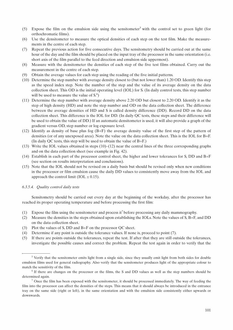
(5) Expose the film on the emulsion side using the sensitometer5 with the control set to green light (for orthochromatic films).
(6) Use the densitometer to measure the optical densities of each step on the test film. Make the measure-ments in the centre of each step.
(7) Repeat the previous action for five consecutive days. The sensitometry should be carried out at the same hour of the day and the film should be placed on the input tray of the processor in the same orientation (i.e. short axis of the film parallel to the feed direction and emulsion side uppermost).
(8) Measure with the densitometer the densities of each step of the five test films obtained. Carry out the measurement in the centre of each step.
(9) Obtain the average values for each step using the reading of the five initial patterns.(10) Determine the step number with average density closest to (but not lower than) 1.20 OD. Identify this step
as the speed index step. Note the number of the step and the value of its average density on the data collection sheet. This OD is the initial operating level (IOL) for S. (In daily control tests, this step number will be used to measure the value of S.6)
(11) Determine the step number with average density above 2.20 OD but closest to 2.20 OD. Identify it as the step of high density (HD) and note the step number and OD on the data collection sheet. The difference between the average densities of HD and S is called density difference (DD). Record DD on the data collection sheet. This difference is the IOL for DD. (In daily QC tests, these steps and their difference will be used to obtain the value of DD.) If an automatic densitometer is used, it will also provide a graph of the gradient versus OD, step number or log exposure level.
(12) Identify as density of base plus fog (B+F) the average density value of the first step of the pattern of densities (or of any unexposed area). Note the value on the data collection sheet. This is the IOL for B+F. (In daily QC tests, this step will be used to obtain the value of B+F.)
(13) Write the IOL values obtained in steps (10)–(12) near the central lines of the three corresponding graphs and on the data collection sheet (see example in Fig. 42).
(14) Establish in each part of the processor control sheet, the higher and lower tolerances for S, DD and B+F (see section on results interpretation and conclusions).
(15) Note that the IOL should not be revised on a daily basis but should be revised only when new conditions in the processor or film emulsion cause the daily DD values to consistently move away from the IOL and approach the control limit (IOL ± 0.15).
6.3.5.4. Quality control daily tests
Sensitometry should be carried out every day at the beginning of the workday, after the processor has reached its proper operating temperature and before processing the first film:
(1) Expose the film using the sensitometer and process it7 before processing any daily mammography. (2) Measure the densities in the steps obtained upon establishing the IOLs. Note the values of S, B+F, and DD
on the data collection sheet. (3) Plot the values of S, DD and B+F on the processor QC sheet. (4) Determine if any point is outside the tolerance values. If none is, proceed to point (7). (5) If there are points outside the tolerances, repeat the test. If after that they are still outside the tolerances,
investigate the possible causes and correct the problem. Repeat the test again in order to verify that the
5 Verify that the sensitometer emits light from a single side, since they usually emit light from both sides for double emulsion films used for general radiography. Also verify that the sensitometer produces light of the appropriate colour to match the sensitivity of the film.
6 If there are changes on the processor or the films, the S and DD values as well as the step numbers should be determined again.
7 Once the film has been exposed with the sensitometer, it should be processed immediately. The way of feeding the film into the processor can affect the densities of the steps. This means that it should always be introduced in the entrance tray on the same side (right or left), in the same orientation and with the emulsion side consistently either upwards or downwards.
101

FIG. 42. Sample film processor QC chart. Note that the measurement on 6 April 2007 was repeated because the initial value offDD was outside the action level.
102
problem has been solved and record the values in the tables for processor control on the data collection sheets.
(6) Note the cause of the problem and type of corrective action carried out on the data collection sheet. (7) Observe if the graphed values are indicative of any trend (three or more values that move in the same
direction). If a trend exists but the points are not outside the control limits, the mammography studies can be carried out. However, it is important to determine the cause of this behaviour and not to wait until the values go outside the permitted limits.
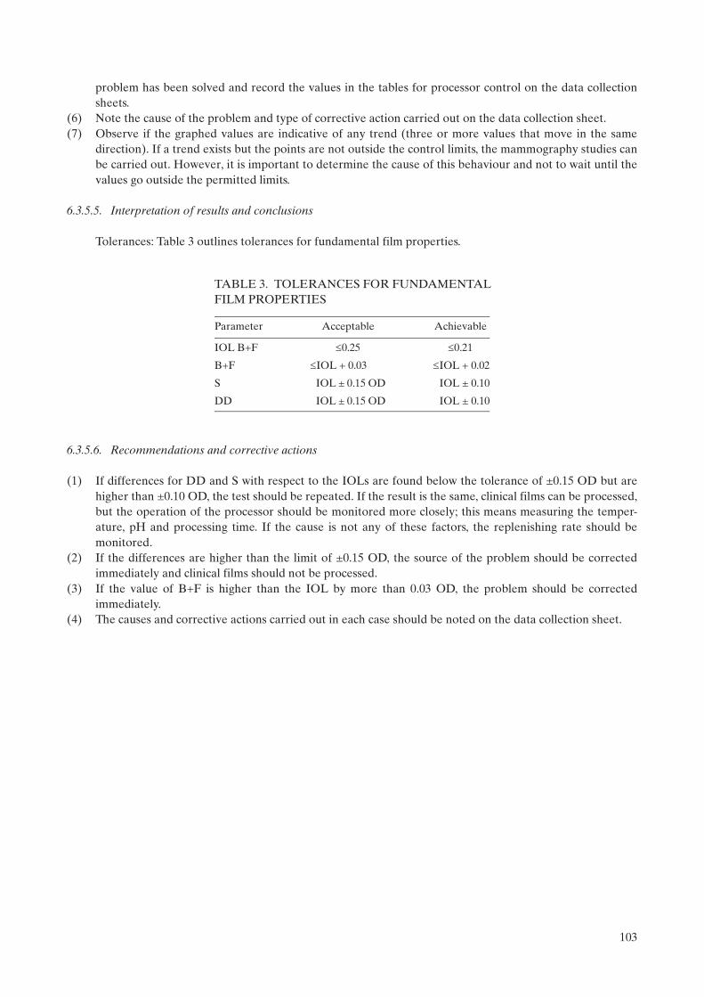
6.3.5.5. Interpretation of results and conclusions
Tolerances: Table 3 outlines tolerances for fundamental film properties.
6.3.5.6. Recommendations and corrective actions
(1) If differences for DD and S with respect to the IOLs are found below the tolerance of ±0.15 OD but are higher than ±0.10 OD, the test should be repeated. If the result is the same, clinical films can be processed, but the operation of the processor should be monitored more closely; this means measuring the temper-ature, pH and processing time. If the cause is not any of these factors, the replenishing rate should be monitored.
(2) If the differences are higher than the limit of ±0.15 OD, the source of the problem should be corrected immediately and clinical films should not be processed.
(3) If the value of B+F is higher than the IOL by more than 0.03 OD, the problem should be corrected immediately.
(4) The causes and corrective actions carried out in each case should be noted on the data collection sheet.
TABLE 3. TOLERANCES FOR FUNDAMENTALFILM PROPERTIES
Parameter Acceptable Achievable
IOL B+F 0.25 0.21
B+F IOL + 0.03 IOL + 0.02
S IOL ± 0.15 OD IOL ± 0.10
DD IOL ± 0.15 OD IOL ± 0.10
103

6.3.6. Artefact detection
6.3.6.1. Scope
— Objective: To determine if the processor introduces artefacts; — References [3–6, 12, 14, 18]; — Frequency: Weekly.
6.3.6.2. Instrumentation
(1) PMMA phantom of 45 mm thickness, free of any imperfections or artefacts. (2) Mammography cassettes and films. (3) Viewbox.
6.3.6.3. Methodology
(1) Select two cassettes that are in optimal condition and load them with mammography films. (2) Put a lead number on the PMMA phantom in the right upper position of the cassettes. (3) Expose each cassette with the automatic exposure control or choose the exposure factors to produce a
phantom image with optical density slightly higher than 1.20 OD. (4) Develop the films under the same conditions used for clinical films. The second film should be introduced
into the processor feed tray perpendicularly with respect to the first one. (5) Observe both films in the viewbox and identify the origin of any spots or marks.
6.3.6.4. Interpretation of results and conclusions
Tolerance: No clinically significant artefacts are present, such as grid lines, blotches, streaks, high or low density striations [14, 19].
6.3.6.5. Recommendations and corrective actions
If artefacts are located on the part of the film where the breast image would appear, the processor maintenance person should be contacted.
104

6.3.7. Transition between film emulsion numbers
6.3.7.1. Scope
— Objective: To determine the transitional change in processor QC parameters when the film emulsion batch is changed or when the brand or manufacturer of films changes;
— References [3–5, 14, 18]; — Frequency: As required.
6.3.7.2. Instrumentation
(1) Sensitometer. (2) Densitometer. (3) Film from two different boxes.
6.3.7.3. Methodology
(1) The transition should be carried out when the box of films for QC needs to be changed or when the brand or manufacturer of films changes.
(2) The transition should be done when at least five films remain in the box. (3) It is necessary to be sure that the processor is operating correctly. (4) At the same hour of the day, expose films from the box in use and films from the new box with the
sensitometer. (5) Calculate the averages of S, B+F and DD for the films of both boxes and note the values on the data
collection sheet. (6) Calculate the differences among the average values of S, B+F and DD obtained from the films from the
new and old boxes. Note them on the data collection sheet. (7) Adjust the new levels in accordance with the differences found in the previous point. This is carried out by
adding the differences, with their sign (positive or negative), to the values corresponding to the operating levels of S, B+F and DD of the old films (see Appendix VI for an example of this procedure).
(8) Record the new operating levels and their respective limits on the data collection sheet and in the graphs on the processor control sheet.
(9) Note the lot number of the box and the day in which the transition was carried out.
105

6.4. IMAGING SYSTEM
6.4.1. Cleaning of intensifying screens
6.4.1.1. Scope
— Objective: To ensure that the intensifying screens of the mammography cassettes are not damaged, are dust-free and without particles or other types of dirt that can degrade or interfere in the detail of the image of diagnostic interest;
— References [3, 5, 6]; — Minimum frequency: Weekly and after changes.
6.4.1.2. Instrumentation
(1) Non-alkaline soap solution composition and concentration as approved by the screen manufacturer.(2) Lint-free cloth.(3) Ultraviolet lamp.(4) Brush.
6.4.1.3. Methodology
(1) Confirm by inspection that the exterior part of the cassette is free of dirt before opening the cassette. (2) Choose a clean area of the darkroom to work in. (3) Dry clean the screens following the recommendations of the manufacturer. (4) With the aid of the ultraviolet lamp, confirm that the screens are free of dust, dirt, lint, streaks and pencil
marks, nail polish residue or other spots. When cleaning is indicated, the intensifying screens should be cleaned with the soap solution and dried with the cloth, leaving the cassette partially open in a vertical position.
(5) After loading the cassettes and before use, wait at least 15 min or for a period of time that is recommended by the manufacturer.
(6) Document these actions on the data collection sheet.
6.4.1.4. Recommendations and corrective actions
Review the cleaning of the darkroom whenever dirt on the screens is detected.
106

6.4.2. Screen film contact and light tightness of cassettes
6.4.2.1. Scope
The air trapped between the screen and the film is a common cause of poor contact in single-screen cassettes. Thus, before commencing mammography with patients, it is important to wait 15 min after loading the cassette. It is recommended that the institution have enough cassettes in order for the quality of the provided service not to be affected.
— Objective: To confirm that the screen film contact is uniform; confirm the light tightness of the cassettes; — References [3–6, 15–17];— Minimum frequency: Semi-annually and after changes.
6.4.2.2. Instrumentation
(1) Screen film contact test tool.(2) Mammography film. (3) Screens and cassettes to be inspected. (4) Densitometer with an aperture of at least 2.0 mm diameter.
6.4.2.3. Methodology
This test should be carried out specifically with a screen film contact test tool designed for QC in mammography and never with one used for general radiology.
(1) Check the cleanliness of the cassettes and the screens to be inspected. If it is necessary to perform moist cleaning of the screens, allow them to dry in air at least 15 min before continuing the test.
(2) Load all the cassettes to be checked with films and wait 15 min to allow the release of trapped air. (3) Number each cassette in order to facilitate its identification.8
(4) Place the numbered cassette on the breast support plate of the mammography unit. (5) Place the screen film contact test tool on the cassette. (6) Make an exposure using a manual radiographic technique (25–28 kVp) to obtain a density between
1.5–2.0 OD. This density range provides an adequate film gradient to facilitate the detection of spots due to poor contact.
(7) Develop the film under the same conditions as clinical mammography studies. (8) Expose the other cassettes under the same conditions. (9) Observe the films in a (previously controlled) viewbox, at a distance of 1 m, looking for dark or clear areas
(bad contact). If necessary, mask the film in order to avoid any excess of light that can dazzle and impede the visualization of poor contact areas.
(10) Check for areas of blackening, most specifically near margins. Measure the size of these areas in each margin of the film. Note the results on the data collection sheet for light tightness.
(11) Re-clean the cassettes which do not pass the test and repeat the test. (12) Place in the viewbox the two images obtained of the cassette that did not pass the test the first time. (13) Observe and compare the poor contact areas in order to see if these areas are found in the same position
(if they are not in the same position, this is probably due to pieces of dust or grit and the cassettes should be cleaned again).
(14) Document this test on the data collection sheet.
8 The screen should be identified in a permanent manner by marking it with an optically opaque marker in an area which receives radiation but is outside the breast. This enables detection and correction of artefacts and other problems seen on clinical images related to a specific screen or cassette.
107
6.4.2.4. Interpretation of results and conclusions
Tolerance:
(1) Acceptable: Small dark spots indicating the areas of poor contact 5 mm in diameter; size of the blackening areas 5 mm in the margins of each edge of the film, except at the chest wall, where 2 mm is the maximum.
(2) The appearance of darkened areas towards the centre of the films is not acceptable.
6.4.2.5. Recommendations and corrective actions
(1) The cassettes that show areas of bad contact are not suitable for clinical use and should be replaced, and matching of the speed should be verified.
(2) The cassettes, which are not light-tight, should be repaired or discarded as indicated.
108

6.4.3. Uniformity of cassette sensitivity, attenuation and artefacts
6.4.3.1. Scope
— Objective: To confirm uniformity in the speed and attenuation of the intensifying screens of the cassettes used in mammography; to evaluate screen and cassette related artefacts;
— References [3–6, 15, 17]; — Minimum frequency: Semi-annually and after changes.
6.4.3.2. Instrumentation
(1) Cassettes used routinely in the mammography service. (2) Phantom ACR accreditation or PMMA with 45 mm of uniform thickness. For artefact evaluation, it is
preferable to use a slab of material that is large enough to cover the entire active area of the image receptor.
(3) Densitometer. (4) Mammography films of the same box. (5) Radiographic markers (numbers).
6.4.3.3. Methodology
(1) Select all the cassettes that are to be evaluated, number them and load them with film.
Perform steps (2)–(9) for each cassette:
(2) Record on the data collection sheet the cassette number, screen type (indicated near the edge of the screen), condition of cassette latches and the reference data of the film used for the test (manufacturer, type and lot number).
(3) Place the phantom on the breast support of the mammography unit, ensuring that it covers the sensors of the automatic exposure control (AEC). With the ACR accreditation phantom, it is necessary to ensure that the sensors are under the central part of the phantom.
(4) It is preferable that the exposure be carried out with the AEC. If the equipment does not have AEC, select the technique factors manually (and use the same for all cassettes). These factors should be those clinically used to obtain images of a breast of 50 mm thickness under compression. Make the exposure, and on the data collection sheet, record the factors used (e.g. density control setting, anode, filter, kVp, mAs) to make the exposure of each cassette.
(5) Develop all the films in the processor normally used for processing the mammography studies. Ensure that the processor is working optimally.
(6) Measure the optical density of the images at a point located 40 mm from the chest wall and laterally centred. For the ACR phantom, measure the optical density in the geometric centre of the image. Note the result on the data collection sheet.
(7) Determine the values of mAs maximum (mAsmax) and minimum (mAsmin), and find the difference (mAsmax – mAsmin) between them. Note the result on the data collection sheet.
(8) Determine the values of maximum optical density (ODmax) and minimum (ODmin), and calculate the difference between them. Note the result on the data collection sheet.
(9) Inspect the film for each cassette for artefacts.
109

6.4.3.4. Interpretation of results and conclusions
Tolerances:
(1) Maximum deviation in OD = ODmax – ODmin:Achievable: 0.2 OD;Acceptable: 0.3 OD.
Record the values on the data collection sheet. (2) Maximum deviation in mAs = 100 (mAsmax – mAsmin)/mAsmean: acceptable 5%.(3) There should be no significant artefacts due to damage to individual screens.
6.4.3.5. Recommendations and corrective actions
(1) Those cassettes that do not perform within acceptable tolerances should be removed from clinical use since they will generate excessive dose values.
(2) Screens with significant artefacts that cannot be removed by cleaning should be replaced. Note that modern screens have a limited life expectancy and should be regularly replaced.
Note: This test assumes that both the film processor and the AEC are stable and operating properly. The processor performance can be verified with sensitometry. AEC performance can be demonstrated by performing this test several times with the same cassette (see Sections 6.3.5 and 6.5.1).
110

6.5. AUTOMATIC EXPOSURE CONTROL
6.5.1. Test of system constancy
6.5.1.1. Scope
— Objective: To confirm that the mammographic X ray unit is producing a consistent optical density and output. The following values must first be established for each unit in conjunction with the medical physics service:• Target optical density (ODtarget): This is the optical density that the unit is aiming for and it should be
selected by taking into account local factors (such as the type of film in use) but should be in the range 1.5–1.9 OD.
• Standard measurement position: This is the location on the film image at which densitometer measure-ments are to be made. It is important to use the same position each time and it should be chosen as a point located 40 mm from the chest wall and laterally centred.
• Baseline mAs: This is the mAs needed to achieve the ODtarget when carrying out the test according to the protocol below.
— References [3–6, 15, 17]; — Minimum frequency: Daily and under circumstances such as following service or repair, after moving a
mobile unit and when malfunction is suspected.
6.5.1.2. Instrumentation
(1) PMMA slab(s) with a total thickness of 45 mm. The slabs should be labelled and the same ones used each time.
(2) A test cassette used for all of the measurements. This is a regular cassette used for clinical mammography; however, this cassette is marked so that it can be used for QC testing.
(3) Densitometer.(4) Film in current use.
6.5.1.3. Methodology
(1) Place the PMMA centrally on the breast support table against and slightly overlapping the chest wall edge. (2) Ensure that the AEC chamber is at the chest wall position. (3) Place the loaded test cassette in the cassette holder. (4) Select all operating parameters as used clinically for this breast thickness. These will include AEC density
control setting, AEC mode, collimator and compression paddle. If kVp/target/filter are selected manually, always use the same settings for this test.
(5) Apply sufficient compression to activate the AEC (if required). Different types of mammography machine have different AEC systems and it is recommended that local testing protocols specify the level of compression applied for this test.
(6) Make an exposure and record all post-exposure factors, such as mAs, target material, filter material and kVp.
(7) If processing facilities are available, process the film after carrying out sensitometry. If processing facilities are not available, the film should be returned with the others for processing and reading.
(8) Measure the resultant optical density at the standard position and record it on the data collection sheet. It is useful to record the optical density graphically in order to identify trends.
(9) Check the film for artefacts and other faults involving, for example, beam alignment, grid lines, scratches and processing.
(10) Record the optical density and exposure factors (target, filter kVp and mAs) used for each exposure. Plot graphs of OD and mAs versus the date as illustrated in Fig. 43.
(11) Record on the data collection sheet if the performance falls outside of tolerances.(12) Comment about the presence of any significant artefacts on the data collection sheet.
111
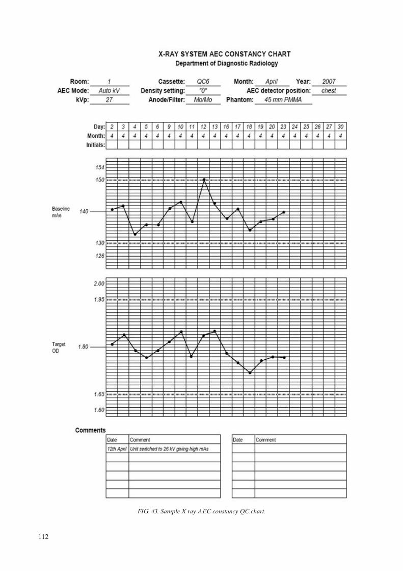
FIG. 43. Sample X ray AEC constancy QC chart.
112
6.5.1.4. Interpretation of results and conclusions
Tolerances:
(1) Constancy of optical density:Achievable: OD = ODtarget ± 0.15;Acceptable: OD = ODtarget ± 0.2;
(2) Constancy of mAs: Acceptable: ± 10% of baseline mAs;(3) No clinically significant artefacts.
6.5.1.5. Recommendations and corrective actions
In case of non-compliance, contact the person in charge of the maintenance service.
113

6.5.2. Test of AEC thickness compensation
6.5.2.1. Scope
— Objective: To confirm that the AEC produces the target optical density and compensates for different thicknesses;
— References [3, 4, 6, 15, 17, 20, 21]; — Minimum frequency: Monthly.
6.5.2.2. Instrumentation
(1) PMMA slabs to be able to produce three thicknesses of approximately 20 mm, 45 mm and 70 mm. (2) Radio-opaque objects for film identification.(3) A test cassette used for all of the measurements. This is a regular cassette used for clinical mammography;
however, this cassette is marked so that it can be used for QC testing. (4) Densitometer.
6.5.2.3. Methodology
(1) Select the clinically relevant automatic exposure mode. Select position ‘0’ or ‘Normal’ or ‘N’ on the density control selector.
(2) Use the same (test) cassette to carry out all the tests. (3) Place the loaded cassette in the Bucky. (4) Place a radio-opaque object to identify the film. (5) Place the thinnest PMMA slab on the breast support, with its edge aligned with the chest wall margin of the
breast support and laterally centred. Confirm that the PMMA covers the AEC sensors completely. It is important that the AEC sensor be placed in the same position every time the test is performed (e.g. at the position closest to the chest wall edge).
(6) If the mammography system is fully automatic (i.e. it automatically selects the target/filter combination and kVp), operate it in this manner. Otherwise, select the kVp and target/filter combination used clinically for a breast corresponding to this absorber. Note the mAs for this exposure.9 Process the film and measure the OD at the standard position.
(7) For each of the other two thicknesses of PMMA, expose a film using the clinically relevant kVp and target/filter combination for that thickness. If automatic mode is used clinically then this mode should be utilized. A technique chart is essential in the absence of automatic mode.
(8) Record the optical densities and exposure factors (target, filter kVp and mAs) used for each exposure. Plot graphs of OD and mAs for the three thicknesses versus the date, as illustrated in Fig. 44.
(9) Record on the data collection sheet if the performance falls outside of tolerances.
6.5.2.4. Interpretation of results and conclusions
Tolerances:
(1) Optical density for each thickness:Achievable: OD = ODtarget ± 0.15;Acceptable: OD = ODtarget ± 0.2;
(2) Exposure (mAs) for each thickness: Acceptable: ±10% of baseline mAs.
9 If it is noticed that the automatic system causes the kVp or target/filter combination to change for different exposures, change the thickness of PMMA slightly (by 5 mm) to force the system to select a single, consistent spectrum. Then repeat the test.
114
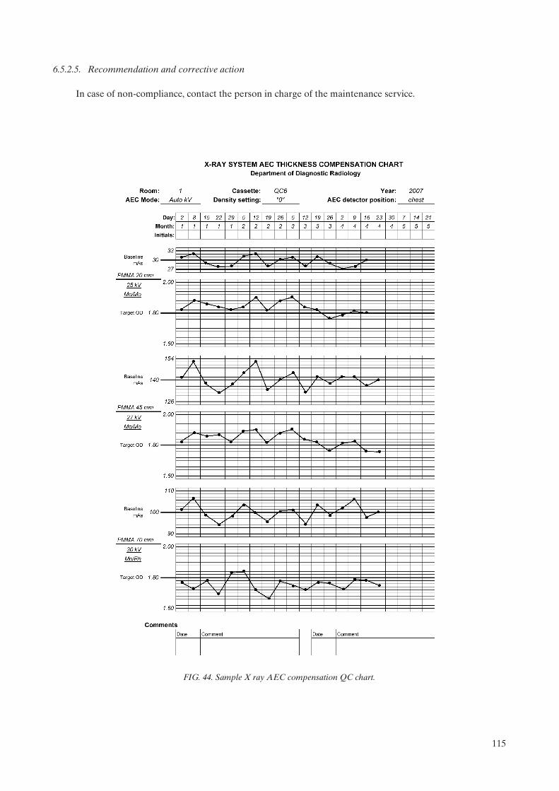
6.5.2.5. Recommendation and corrective action
In case of non-compliance, contact the person in charge of the maintenance service.
FIG. 44. Sample X ray AEC compensation QC chart.
115
6.6. IMAGE QUALITY
6.6.1. Evaluation of image quality
6.6.1.1. Scope
— Objective: To ensure that image quality is acceptable; — Reference [3]; — Minimum frequency: Weekly.
6.6.1.2. Instrumentation
(1) Breast phantom (see Section 7.6.1 for details).(2) Cassette (it is recommended that the same cassette always be used) and film. (3) Magnifier: 2× or greater. It is recommended that the magnifier contain a second area that provides 4× or
5× magnification.(4) Viewbox.
6.6.1.3. Methodology
(1) Load the cassette with a film from the box that is in use for patients. Wait the amount of time recommended in order to have good screen film contact. (If it is the first film taken from a new box, note the emulsion number in the data collection sheet.)
(2) Place the loaded cassette in the Bucky. (3) Place the phantom on the breast support aligned with the chest wall and centred laterally.(4) Place the PMMA disc on the phantom in such a way that it does not interfere with any phantom detail or
the AEC sensor. It is recommended that it be located slightly below and between the first and the second fibre.
(5) Lower the compression paddle until it touches the phantom. (6) Confirm that the AEC sensor is under the phantom. (7) Select the technique factors that are used in clinical practice: target, filter, kVp, grid, density control
position, operation mode (semi-automatic or automatic). (8) Make an exposure. (9) Record the mAs on the corresponding data collection sheet. Check that the kVp and target/filter are as
established at the baseline. If not, comment on the data collection sheet. (10) Process the film in the processor normally used for mammography, introducing it always with the same
orientation. (11) View the film with the magnifier on the viewbox used clinically, placing a mask over the area of the viewbox
that is not being used, and with a very low level of environmental illumination in the reading room. (12) Evaluate the image according to the evaluation method (see Section 7.6.1). Note the results on the data
collection sheet. (13) Observe the image and determine if there are significant artefacts. Record in the comments section of the
data collection sheet. Investigate the causes of any artefacts.
6.6.1.4. Interpretation of results and conclusions
Tolerances:
(1) Image contrast index: Achievable: 0.55;Acceptable: 0.40 for the ODD between PMMA disc and adjacent point;
116

(2) Image quality: Acceptable: fibres: 4;Microcalcifications: 3;Masses: 3.
6.6.1.5. Recommendations and corrective actions
(1) If the image contrast index or image quality deteriorates over time, it will be necessary to carry out other
tests (e.g. kVp, AEC, processor) to determine the source of the change.10
(2) If there are several different types of film in use, this test should be carried out for each type.
10 Due to the subjective component associated with the observer, it is recommended that the test always be performed by the same person, using the same criteria, viewbox, magnifier lens and illumination conditions.
117

6.7. FILM REJECTION RATE
6.7.1. Film rejection rate
6.7.1.1. Scope
— Objective: To identify the causes of the film rejection and the most urgent needs for action in order to improve the operation of the service;
— References [3, 5, 6, 11, 22]; — Minimum frequency: Quarterly.
6.7.1.2. Instrumentation
Rejected films.
6.7.1.3. Methodology
(1) Collect the rejected films during a period of 15 days or a month (the actual collection time will depend on the rejection rate).
(2) Note on the data collection sheet the number of total studies conducted in the same period. (3) Note on the data collection sheet the person responsible (radiologist or technologist) who decided that the
image or images be repeated. (4) Identify in each case the explicit cause or causes of the rejection and standardize them with a code. Take
note of them on the data collection sheet together with the projection type (e.g. CC, MLO, Lat). (5) Note on the data collection sheet the incidence of each rejection cause.(6) Obtain the total number of films used in the same period based on a reliable source (e.g. data from the film
warehouse, from the exposure or processed film counters, from the service statistics). If possible, the number of films used for QC testing and other non-patient exposures should be excluded. This will yield a more realistic rejection rate.
(7) Calculate the rejection rate as the quotient between the number of rejected films and the total number of films used during a certain time period, expressed as a percentage.
6.7.1.4. Interpretation of results and conclusions
Tolerances:
Achievable: <3%;Acceptable: <8%.
6.7.1.5. Recommendations and corrective actions
Analyse the reasons for the rejection of images so that remedial action may be implemented with regard to the most serious causes. However, on many occasions it will be impossible to judge whether the image system is working adequately. The film rejection rate is a global indicator of the necessity for monitoring the QC programme.
Note: Low rejection rates may in fact indicate that radiologists are accepting films that should be repeated, rather than indicating good practice.
118

7. MEDICAL PHYSICIST’S TESTS
The tests to be performed by the medical physicist are listed in Table 4. The order in which tests are performed does not necessarily have to be the same as that in which they appear in this publication. The preferred order will depend on various factors relating to the mammography facility and the medical physicist’s preferences. It should always be considered that some test results are required before other tests can be performed effectively. In some cases, the medical physicist may also be responsible for performing some of the tests described in the radiographer’s section. Data collection sheets for the medical physics tests are found in Annex II and are available in electronic format. All annual tests would also be done at acceptance. Additionally, at commissioning the baseline values for the radiographer’s tests would be established. This requirement is indicated in the test descriptions themselves and is also indicated in the column labelled ‘suggested frequency’ of Table 4.
TABLE 4. LIST OF MEDICAL PHYSICIST’S TESTS
TestPriority(Ea, Db)
Suggestedfrequency
Tolerances
Unit assembly evaluation
Unit assembly evaluation E Annually See Section 7.1
Sensitometry and darkroom
Sensitometry and darkroom E At commissioning and annually
See Section 7.2.1
Darkroom radiation level D As required Acceptable: <20 Gy/week
Radiological equipment
Radiation leakage D At acceptance and after changes
Acceptable: 1 mGy/h at 1 m
Accuracy and repeatability of the tube kVp
E Annually Acceptable: Accuracy: 5%Repeatability: difference 5% or COVc 2%
Half-value layer (HVL) E Annually See Section 7.3.3.5
Output: repeatability and linearity E Annually Acceptable:Repeatability: difference 5% or COV 5%;Linearity: 10%
Normalized output value D Annually Acceptable: >30 Gy/mAs at 1 m, 28 kVp, Mo/Mo
Compression
Compression force and thickness E Annually See Section 7.3.5.4
Automatic exposure control
Repeatability of the automatic exposure control
E Annually Acceptable: COV in mAs: 5%
Constancy of ODd with baseline value E Annually Acceptable: OD = ODtarget ± 0.20
Exposure time for 45 mm slab E Annually Contact mammography:Achievable: t 1.5 s Acceptable: t 2 s
Magnification mammography:Achievable: t 2 s Acceptable: t 3 s
119

TestPriority(E, D)
Suggestedfrequency
Tolerances
Compensation of the AECe for different thickness and beam quality
E Annually Achievable: OD = ODtarget ± 0.15Acceptable: OD = ODtarget ± 0.20
Increase of OD for each step of the density control
E Annually Acceptable: f OD = 0.1–0.2
Collimation system
Light field/radiation field coincidence
D Annually Achievable: 1% of FFDg all edges
Radiation field/image receptor coincidence
E Annually Achievable: completely irradiate the image receptor, but does not extend beyond the shielded breast support except at the chest wall where it may extend by 5 mm (see Section 7.4.1.4)
Acceptable: as above for the chest wall and within the breast support by 2% FFD for the other edges
Compression paddle/breast support alignment
E Annually Acceptable: paddle not visible in image and edge of paddle 1% of FFD beyond chest wall edge of image receptor
Image viewing conditions
Luminance of the viewboxes E Annually >3000 cd/m2 (nit)
Viewboxes homogeneity and colour E Annually Acceptable: <30% for each viewbox and <15%between panels in a viewbox
Ambient interpretation room illumination
E Annually Achievable: 10 lxAcceptable: 50 lx
Image quality
Target background density E Annually Acceptable: OD = ODtarget ± 0.20
Optical density difference between disc and background
E Annually Achievable: 0.55 OD Acceptable: 0.40 OD
Phantom image quality evaluation (ACRh)
E Annually Acceptable: Fibre score 4 Speck score 3 Mass score 3
System spatial resolution E Annually Achievable: 15 lp/mm Acceptable: 11 lp/mm
Dosimetry
Mean glandular dose (DG) E Annually Achievable: DG 2 mGy Acceptable: DG 2.5 mGy
a E: Essential, basic requirement. b D: Desirable, recommended. c COV: Coefficient of variation.d OD: Optical density. e AEC: Automatic exposure control.f : Change in parameter.g FFD: Focus film distance.h American College of Radiology.
Note: The ACR phantom has been taken as an example because it is probably the one most commonly used.
TABLE 4. LIST OF MEDICAL PHYSICIST’S TESTS (cont.)
120

7.1. UNIT ASSEMBLY
7.1.1. Unit assembly evaluation
The medical physicist should carry out an inspection of the mammography facility to ensure that the mechanical features of the unit are functioning correctly and that basic safety features are in place. The following guidelines should be followed:
— Verify that the free-standing unit is mechanically stable under normal operating conditions.— Check that indicator lights are working properly.— Confirm that all moving parts move smoothly, without obstructions to motion, and no obstructions hinder
the full range of motions within these limits.— Check that all locks and detents work properly by setting them and confirming that the relevant
mechanical motion is inhibited.— Check that the angulation indicators function properly.— Confirm that the image receptor and holder assembly is free from wobble or vibration during normal
operation (exposure).— Establish that the image receptor slides smoothly into the holder assembly and is held securely regardless
of gantry orientation.— Inspect the compression paddles to confirm they are in good condition.— Verify by direct measurements that the compression breast thickness scale (analog or digital) is accurate to
within 5 mm and reproducible to within 2 mm under conditions of moderate compression. Measure-ments should be performed for at least the small and large image receptors and compression paddles if applicable (see also Section 7.3.5).
— Test that the automatic compression release following exposure functions correctly and can be overridden to maintain compression if required.
— Confirm, by switching the power OFF, that the compression can be released manually in the event of power failure.
— Verify that the operator shielding is adequate during exposure at the operator’s position.— Inspect the unit to confirm that neither the patient nor the operator is exposed to sharp or rough edges or
other hazards.— Confirm that appropriate, current operator technique control charts are posted.
7.1.1.1. Scope
— Objective: To evaluate mechanical functionality and safety of the mammography unit; — References [3, 4]; — Minimum frequency: At acceptance, annually, and after changes that can alter the mechanical function of
all or part of the unit.
7.1.1.2. Instrumentation
Tape measure or ruler.
7.1.1.3. Methodology
Record the results of the inspection on the data collection sheet.
7.1.1.4. Recommendations and corrective actions
Items that are hazardous, inoperative or fail to operate correctly should be repaired by the appropriate equipment manufacturer.
121

7.2. SENSITOMETRY AND DARKROOM
7.2.1. Sensitometry and darkroom conditions
It is essential that the medical physicist review the site sensitometric QC records, and desirable that he/she measure the full sensitometric curve of the film in clinical usage. The procedure is described in Section 6.3.5, however, all optical density steps should be measured and the sensitometric curve plotted (OD versus log exposure). Information on the exposure increments will be available in the sensitometer’s manual. In addition, the gradient of the film should be calculated between net densities of 1.0 and 2.0 (see Appendix VII). Alternatively, this could be done using an automatic reading densitometer [14].
This is particularly important during commissioning when assisting in the establishment of the site QC programme. Annual test results should be compared with those from previous visits or from other sites using the same film. The purpose of this measurement is to help standardize performance among multiple facilities.
Similarly, it is essential that the physicist review the darkroom conditions and the associated radiographer tests. This involves checking temperature, humidity, ventilation conditions and radiation level survey, if required, as described in Appendix III. This assessment is essential at acceptance testing and ideally would follow previous consultation in the design phase of the facility. Annual tests would include the flutter test (see Section 6.2.1) and any other actions dictated by a review of conditions.
122

7.3. RADIOLOGICAL EQUIPMENT
7.3.1. Radiation leakage
7.3.1.1. Scope
— Objective: To evaluate radiation leakage of the X ray tube; — References [3, 4]; — Minimum frequency: At acceptance, and after changes in the X ray housing that could influence radiation
levels.
7.3.1.2. Instrumentation
(1) Lead (sheet, shielded apron with lead, etc.); (2) Loaded cassette or radiographic films for direct exposure; (3) Appropriate radiation detector for measurement of leakage radiation.
7.3.1.3. Methodology
(1) Place a lead sheet in the collimator in order to ensure that no primary radiation can escape. (2) Cover the head of the X ray tube with loaded cassettes (or films for direct exposure), marking them to
allow subsequent identification of their position. (3) Make an exposure, selecting the maximum value of kVp and a reasonable value of mAs that ensures
damage to the tube will be avoided. (4) Process the films and identify those in which the points with the greatest degree of blackening are
observed. These points indicate the presence of radiation leakage.(5) If leakage is detected, it should be quantified as follows:
— Measure the air kerma at the point or points at which radiation leakage has been noticed. Place an appropriate ionization chamber at a known distance close enough to obtain a reliable measurement, but no closer than 20 cm from the focal spot.
— Note these values on the data collection sheet.
7.3.1.4. Calculation procedure
(1) Transform the readings obtained to mGy/h at a distance of 1 m from the focus and at the maximum tube loading for 1 h, applying the following formula:
(1)
where K·RF is the radiation leakage rate (kerma), d is the distance in metres from the focal spot to the point
where the ionization chamber is located, mAsmax is the maximum tube loading per hour of the X ray tube specified by the manufacturer, mAs0 is the actual tube loading used and K0 is the reading from the radiation detector.
(2) Record the results on the data collection sheet.
K RF = ¥ ¥mAs
mAsK dmax
00
2
123

7.3.1.5. Interpretation of results and conclusions
Tolerance:
Acceptable: K·RF < 1 mGy in 1 h, at a distance of 1 m from the focus, and at the maximum output rate (power), as averaged over an area that does not exceed 100 cm2.
7.3.1.6. Recommendations and corrective actions
If values exceed tolerance, it will be necessary to contact the equipment manufacturer to correct the problem.
124

7.3.2. Accuracy and repeatability of kVp
7.3.2.1. Scope
— Objective: To verify the accuracy and repeatability of the kVp; — References [3, 15, 20]; — Minimum frequency: At acceptance, annually (essential), or semi-annually (desirable), and after changes
that can alter the kVp of the X ray tube.
7.3.2.2. Instrumentation
A kVp meter (non-invasive type).
7.3.2.3. Methodology
(1) Check that the line voltage of the electricity supply connected to the X ray equipment is stable, if applicable. If not, contact the service engineer.
(2) Select a number of kVp settings commonly used in the clinical practice range (e.g. 25–35 kVp). (3) Note on the data collection sheet the selected values and size of the focuses used.(4) Normally, the compression paddle can be left in place.11 (5) Position the measuring instrument on the breast support and centre it in the radiation field. (6) If it is possible, adjust the field size to the one specified for the measuring instrument.(7) In manual mode (without AEC), carry out two exposures at 28 kVp (a value of mAs in the range of 30–40
can be used; or the value recommended by the manufacturer of the instrument) and note the measured values and the mAs used.
(8) Use the calculation procedure to calculate the percentage difference between the two measurements. If the two measurements do not differ by more than 5%, go to step (10).
(9) If the two measurements differ by more than 5%, take another three measurements at the same setting.(10) Carry out a single exposure for the other kVp settings selected and note the values measured on the data
collection sheet.
7.3.2.4. Calculation procedure
Repeatability:
(1) Calculate the measurement percentage difference using the following formula:
Difference (%) = (maximum measurement – minimum measurement)/minimum measurement
(2) If five measurements are made for the same kVp (28 kVp), calculate the coefficient of variation (COV) of tube voltage.
11 Consult the specifications of the kVp meter to check if it is calibrated for measuring with the breast compression paddle interposed in the field.
125
Accuracy:
(1) For each selected kVp, determine the percentage deviation between the nominal value and the measured kVp (for 28 kVp, take the first value or the average value if more than two readings are made) in accordance with the following equation:
(2)
where kVpnom is the value indicated on the equipment and kVpmeasured is the measured value. This percentage deviation may be taken as a measure of the accuracy.
(2) Note on the data collection sheet the values obtained.
7.3.2.5. Interpretation of results and conclusions
Tolerances:
(1) Acceptable: Accuracy: ±5%;Repeatability: difference 5% or COV 2%;
(2) If there is one or more of the measured kVp values outside the tolerance, note it as unacceptable in the summary data collection sheet.
7.3.2.6. Recommendations and corrective actions
In case of non-conformance, the equipment should be reviewed by the person in charge of maintenance, within a period of 30 days.
Deviation nom measured
nom
(%) =-
100kVp kVp
kVp
126
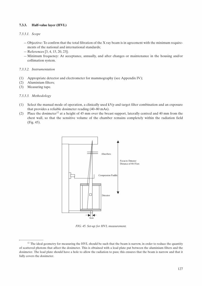
7.3.3. Half-value layer (HVL)
7.3.3.1. Scope
— Objective: To confirm that the total filtration of the X ray beam is in agreement with the minimum require-ments of the national and international standards;
— References [3, 4, 15, 20, 23]; — Minimum frequency: At acceptance, annually, and after changes or maintenance in the housing and/or
collimation system.
7.3.3.2. Instrumentation
(1) Appropriate detector and electrometer for mammography (see Appendix IV);(2) Aluminium filters; (3) Measuring tape.
7.3.3.3. Methodology
(1) Select the manual mode of operation, a clinically used kVp and target filter combination and an exposure that provides a reliable dosimeter reading (40–80 mAs).
(2) Place the dosimeter12 at a height of 45 mm over the breast support, laterally centred and 40 mm from the chest wall, so that the sensitive volume of the chamber remains completely within the radiation field (Fig. 45).
12 The ideal geometry for measuring the HVL should be such that the beam is narrow, in order to reduce the quantity of scattered photons that affect the dosimeter. This is obtained with a lead plate put between the aluminium filters and the dosimeter. The lead plate should have a hole to allow the radiation to pass; this ensures that the beam is narrow and that it fully covers the dosimeter.
Compression Paddle
Absorbers
Detector
4cm
Focus to Detector
Distance of 40-55cm
FIG. 45. Set-up for HVL measurement.
127

(3) If it is possible, collimate the radiation field to cover the sensitive volume of the chamber. (4) Place the compression paddle13 approximately halfway between the focus and the dosimeter. (5) Carry out an exposure and record the reading on the data collection sheet. (6) Put 0.3 mm of aluminium on the compression paddle, totally covering the active volume of the chamber,
and make an exposure with the same parameters. Check that the reading is higher than half of the reading without the filter. If it is not, use a thinner aluminium thickness.
(7) Add 0.1 mm of Al (total 0.4 mm Al) and repeat the previous step. Check that the reading is smaller than half of the reading without the filter. Otherwise, add more Al until the reading falls below half of the reading without the filter.
(8) Remove all the filters and repeat the exposure again. Take note of the reading. (9) Repeat this procedure for other clinically relevant filter/anode combinations.
7.3.3.4. Procedure of calculation
(1) Calculate the value of the HVL, based on the following expression:
(3)
where:t1and t2 are the thicknesses (in mm) of the filters used;M1 and M2 are the average values of the readings measured in steps (6) and (7);M0 is the average value of the reading measured without any added filter.
(2) Note the calculated HVL on the data collection sheet.
7.3.3.5. Interpretation of results and conclusions
Tolerance:
Acceptable: kVp/100 + 0.03 HVL kVp/100 + C
where:C = 0.12 for Mo/Mo
0.19 for Mo/Rh0.22 for Rh/Rh0.30 for W/Rh
and kVp is the measured value for the nominal kVp selected.
Record on the data collection sheet whether the value of the HVL is acceptable.14
7.3.3.6. Recommendations and corrective actions
If the HVL is very low or very high, suspend use of the unit immediately, until the problem is solved.
13 For the calculation of mean glandular dose it is necessary to measure the HVL with the compression paddle in the beam. If it is desired to compare HVL with the manufactuer’s specification, which follows IEC standards, the measurement of HVL would be done without the compression paddle.
14 If this tolerance is met, it is generally the case that regulatory requirements for total beam filtration without compression paddle will also be satisfied.
HVLt M M t M M
M M=
⎡⎣ ⎤⎦ − ⎡⎣ ⎤⎦⎡⎣ ⎤⎦
2 1 0 1 2 0
1 2
2 2ln ln
ln
128

7.3.4. Output repeatability and linearity
7.3.4.1. Scope
— Objective: To evaluate the repeatability of the air kerma for a given mAs, the linearity with the mAs and the normalized output value (Gy/mAs at 1 m);
— References [3, 4, 15, 20, 23]; — Minimum frequency: At acceptance, annually, and after changes.
7.3.4.2. Instrumentation
(1) Appropriate dosimeter and electrometer for mammography. (2) Measuring tape. (3) Thermometer (if an ionization chamber requiring temperature correction is used). (4) Barometer (if an ionization chamber requiring pressure correction is used).
7.3.4.3. Methodology
(1) Place the dosimeter at a known height above the breast support (such as 45 mm or 100 mm), laterally centred and 40 mm from the chest wall, so that the sensitive volume of the dosimeter remains completely irradiated. Measure and note the focus–dosimeter distance.
(2) Select manual mode, the Mo/Mo target filter combination, and 28 kVp. (3) Select three values of mAs from among the ones commonly used in the clinical practice. (4) Fix the first selected value of mAs and carry out two exposures. Record the readings on the data collection
sheet. (5) Calculate the percentage difference between the two measurements. If the two measurements do not differ
by more than 5%, go to step (7).(6) If the two measurements differ by more than 5%, take another three measurements at the same setting.(7) Take a single exposure for each of the other values of mAs. (8) If there are other filter target combinations, the output is also measured for those combinations, selecting
the highest kVp most commonly used in the clinical practice. In this case, it is necessary to check that the dosimeter is calibrated for those beam qualities.
7.3.4.4. Calculation procedure
Repeatability of the kerma (mGy):
(1) Calculate the measurement percentage difference using the following formula:
Difference (%) = (maximum measurement – minimum measurement)/minimum measurement
(2) If five measurements are made for the same output factors, calculate the coefficient of variation (COV) of the air kerma.
Linearity of the output (µGy/mAs):
(1) For each mAs selected, calculate the average value of the obtained readings of air kerma and record it on the data collection sheet.
(2) Calculate the output, Y, by dividing each average air kerma value obtained by the corresponding mAs and record the results.
(3) Take two output values (Y1 and Y2) at consecutive mAs settings and calculate the linearity (L) using L = 100* (Y1 – Y2)/(Y1 + Y2).
(4) Note the result on the data collection sheet.
129

Normalized output (µGy/mAs at 1 m):
(1) Calculate the average value of the output for the different values of mAs. (2) Apply an inverse square law correction to the result to obtain the output at a distance of 1.0 m from the
focus. Multiply by the pressure and temperature correction factor if necessary. Record this value in Gy/mAs at 1 m.
(3) Note the results on the data collection sheet.
7.3.4.5. Interpretation of results and conclusions
Tolerances:
(1) Acceptable: Repeatability: difference 5% or COV 5%;Linearity: <10%;Normalized output: >30 µGy/mAs at 1 m (28 kVp, Mo/Mo);
(2) Indicate in the data collection sheet whether the tolerances are met.
7.3.4.6. Recommendations and corrective actions
If the system is operating outside the tolerance range, contact the person in charge of the maintenance service.
130

7.3.5. Compression
7.3.5.1. Scope
— Objectives: To check that the mammography system provides an adequate compression in manual and automatic mode; to check the accuracy (or deviation) of the indicator of the compression force when it is present on the equipment; to check the accuracy of the compression thickness indicator;
— References [3, 4, 15]; — Frequency: At acceptance, annually, and if a reduction in breast compression is observed.
7.3.5.2. Instrumentation
(1) Platform scales (conventional, analog type, non-digital). (2) Bath towels (cloths), blocks of rubber foam or tennis ball.(3) Slabs of PMMA used for AEC testing.
7.3.5.3. Methodology
Power compression mode:
(1) Place a bath towel on the Bucky and the platform scale over it. Centre the scale directly under the compression paddle.
(2) Place one or more towels (or block of rubber foam) on the scale in order to protect the compression paddle but such that it does not obscure the reading on the scale.
(3) Activate the compression paddle so that it operates and stops at the maximum available force. (4) Read and write the value of the compression force on the data collection sheet. (5) Release the compression.
Manual mode:
(1) Using the manual compression mode, move the compression paddle until it stops. (2) Read and record the compression force on the data collection sheet. (3) Release the compression.
Compression thickness:
(1) Align a 20 mm thickness of PMMA with the chest wall edge of the breast support platform. Ideally, 18 × 24 cm slabs of PMMA should be used to prevent deformation of the plate and reduce measurement inaccuracies on the indication of thickness due to the tilt angle of the plate. If semicircular slabs are used, they may be aligned perpendicular to the chest wall to minimize both of these effects.
(2) Ensure that the compression plate is in contact with the PMMA. (3) Apply a compression force of between 50 N and 100 N. Once the applied force for this measurement has
been established, the same force is used for all subsequent measurements. (4) Note the distance from the compression plate to the breast support platform on the midline at the chest
wall, which is equal to the thickness of the slabs.(5) Compare measured and displayed values.(6) Repeat procedure for at least 45 mm and 70 mm thicknesses of PMMA.(7) If necessary, repeat the measurements in magnification mode.
131

7.3.5.4. Interpretation of results and conclusions
Tolerances:
(1) Achievable: Displayed thickness within ±5 mm of phantom thickness.15
(2) Acceptable: The maximum compression force for powered compression should be no less than 150 N and no more than 200 N. Displayed value accuracy: ±20 N. Maximum manual compression force: <300 N.
7.3.5.5. Corrective actions
If the measured values from these tests are outside tolerance, the compression device should be calibrated by a qualified service engineer.
15 The displayed compressed breast thickness may be used to choose the technique factors so that it is important that this level of accuracy be achieved.
132

7.3.6. Evaluation of the automatic exposure control
Each facility should establish a target optical density for mammography at commissioning. This is the optical density that the radiologist considers optimal for imaging. It is helpful for the medical physicist to provide advice on this matter, but in any event, the preferred target optical density should be in the range of 1.5–1.9. A service engineer may be required to adjust the AEC to obtain this target value. If a facility is not able to provide viewboxes producing a luminance of at least 3000 cd/m2, it will be difficult for the radiologist to view a film exposed to such a density. Under such conditions, it is likely that a lower target optical density will be chosen. If this is done, it must be realized that this will cause the film to be used in a suboptimal manner and there is a high probability that this will reduce diagnostic accuracy.
Important: Prior to conducting this test, the proper operation of the processor should be confirmed by checking the results of the sensitometry test.
7.3.6.1. Scope
— Objectives: To test the repeatability of the AEC; to establish the baseline value for the target optical density under AEC and ensure that this target is maintained with time; to evaluate the exposure time for a 45 mm thick PMMA test slab; to test the compensation of the AEC for different beam qualities and thick-nesses; to test the performance of the density control;
— References [3, 4, 15, 20, 21]; — Minimum frequency: At acceptance/commissioning, annually, and after changes in the equipment, in the
image receptor and/or in the processor.
7.3.6.2. Instrumentation
(1) A set of PMMA slabs to give a total thickness of 2.0 cm, 4.5 cm and 7.0 cm.(2) Appropriate spacers (e.g. radiolucent U-shaped expanded polystyrene spacers of 8 mm thickness). (3) Exposure timer.16
(4) Radio-opaque markers for film identification.(5) Loaded cassettes.(6) Densitometer.
7.3.6.3. Methodology
(1) Select the clinically relevant automatic exposure mode. Select position ‘0’ or ‘normal’ or ‘N’ on the density control selector.
(2) Use the same cassette to carry out all the tests. (3) Place the loaded cassette in the Bucky. (4) Place a 45 mm thickness of PMMA aligned with the chest wall margin of the breast support and
laterally centred and with the U-shaped polystyrene spacer on top to achieve a total thickness of 53 mm. Confirm that the PMMA covers the AEC sensors completely. It is important that the AEC sensor be placed in the same position every time the test is performed (e.g. at the position closest to the chest wall edge).
(5) Place a radio-opaque marker to identify the film.
16 If the system provides a readout of the post-exposure mAs and the mA is known, the exposure time can be calcu-lated from this information without the need of an external exposure timer.
133
(6) If the mammography system is fully automatic (i.e. selects automatically the target filter combination and kVp), operate it in this manner. Otherwise, select the kVp and target filter combination used clinically for a breast whose X ray attenuation is equivalent to the 45 mm of PMMA17, for example 28 kVp; and make three exposures under the same conditions, keeping the same film in the cassette for AEC repeatability assessment. Note the mAs for each exposure.18
(7) Replace the film and make a single exposure under the same conditions.(8) Process this film and all subsequent films according to the manufacturer’s recommendations.(9) Measure the OD at a point placed at 40 mm from the chest wall, laterally centred, and record this value on
the data collection sheet. (10) From the single exposure, determine the exposure time using a suitable exposure timer if needed.(11) Compare the measured optical density with the target optical density, ODtarget, established at commis-
sioning. If it differs by more than 0.2 OD, the density control should be adjusted to provide the correct target optical density. If the target optical density is 1.7 and the measurement is 1.4, for example, a density setting of +1 or +2 is likely to provide the proper OD. The remaining tests are then performed using this setting as the reference. When the next routine servicing is performed on the system, the density control should be recalibrated to provide this OD at the ‘0’ setting.19
(12) Select other thicknesses of PMMA (20 mm and 70 mm). Expose a single film at each thickness using the clinically relevant kVp and target filter combination for that thickness. If automatic mode is used clinically, then this mode should be utilized. A technique chart is essential in the absence of automatic mode.
(13) Make an exposure at those positions of the density control that provide an OD within 0.3 of the ‘0’ position using the beam quality settings selected in step (6) and 45 mm of PMMA. Note the mAs.
(14) Process the films and measure the optical densities at a point placed at 40 mm from the chest wall and laterally centred; record these values on the data collection sheet.
(15) Repeat the above tests for each receptor size. (16) Repeat the above tests in the configuration used for magnification mammography if applicable.
7.3.6.4. Calculation procedure
Repeatability:
(1) Calculate the mean and standard deviation of the four mAs values.(2) Calculate the coefficient of variation (COV) of the four mAs values.
Exposure time for the 45 mm PMMA slab: If an external exposure timer is not used, divide the post-exposure displayed mAs by the nominal mA and record the calculated time on the data collection sheet.
17 A 45 mm thick PMMA slab is equivalent to a 53 mm thick breast, and the use of plastic spacers is recommended to ensure the paddle is at 53 mm above the breast support. In some systems the paddle height will affect the automatic selection of exposure technique factors.
18 If it is noticed that the automatic system causes the kV or target filter combination to change for different exposures, change the thickness of PMMA slightly (by 5 mm) to force the system to select a single, consistent spectrum. Then repeat the test.
19 If it is found necessary to recalibrate the ‘0’ or ‘normal’ setting of the AEC control, it is important to understand the underlying reason for this. A shift in sensitivity or X ray attenuation of one of the components of the imaging system can cause a need to employ either more or less radiation to achieve a particular OD. This may be the result of a conscious decision (e.g. replacing the screen film combination with one that is more sensitive or less noisy), in which case this can be acceptable, or it may signal a problem that must be corrected (e.g. poor processor replenishment) rather than masking the problem by readjusting the AEC control.
134

Constancy of OD with baseline value:Compare the measured OD in the films obtained with a thickness of 45 mm PMMA and the density control in position ‘0’, ‘normal’ or ‘N’ with the baseline ODtarget established at commissioning (see Section 7.3.6.3, step (9)).
Compensation for different thicknesses and beam quality: For each film, calculate the difference between the measured OD and the ODtarget, and record the values on the data collection sheet.
Density control performance:
(1) Calculate the differences in OD between films obtained for adjacent steps of the density control. (2) Note the mAs corresponding to each step of the density control.(3) Determine the mAs difference for consecutive steps of the density control, expressed as a percentage of
the lower value.
7.3.6.5. Interpretation of results and conclusions
Tolerances:
(1) Repeatability: Acceptable; COV in mAs 5%. (2) Exposure time for 45 mm slab:
Achievable: contact mode 1.5 s, magnification mode 2 s ;Acceptable: contact mode 2 s, magnification mode 3 s.
Note: Meeting these tolerances should ensure that the impact of movement artefacts and film reciprocity law failure of the film on the image quality is minimized.
(3) Constancy of OD with baseline value: Acceptable: OD = ODtarget ± 0.20.(4) Compensation for different thicknesses and beam quality:
Achievable: OD = ODtarget ± 0.15;Acceptable: OD = ODtarget ± 0.2 for both contact and magnification mammography.
(5) Density control: Change in OD for different steps: Acceptable: 0.1–0.2 OD.20
7.3.6.6. Recommendations and corrective actions
(1) The AEC should be adjusted to obtain a target optical density between 1.5–1.9 OD when the density control is in position ‘0’ (‘normal’ or ‘N’). If this is not fulfilled, it should be determined which position of the density control is required to obtain this range of OD. The determined position should be recommended for clinical use until the maintenance person adjusts the AEC.
(2) Because of the lower mA available with the small focal spot (magnification mode), the exposure times may be expected to be considerably longer than in contact mode. If times are found to be excessive and patient motion is a concern, an increase in kVp should be considered.
(3) In case of any non-compliance, contact the person in charge of the maintenance service.
20 An alternative approach, which will reduce the amount of film required for testing, is for the physicist to establish the relationship between a change in mAs (near the target operating point) and the change in OD for the film product used, and then to determine that the AEC adjustment provides for an adequately small change in OD to meet this requirement.
135

7.4. COLLIMATION SYSTEM
7.4.1. Collimation system
7.4.1.1. Scope
— Objective: To evaluate the coincidence between the radiation field and the image receptor; to evaluate the coincidence between the light field and the radiation field; to evaluate the alignment of the compression paddle with the margin of the breast support;
— References [3, 20, 24];— Minimum frequency: At acceptance, annually, and after changes.
7.4.1.2. Instrumentation
(1) Six radio-opaque objects (e.g. coins or clips): five of the same size and one larger.(2) Two loaded mammography cassettes: one that fits the Bucky and another, larger one, whenever possible.(3) Ruler.
7.4.1.3. Methodology
(1) Place the larger cassette on the breast support, so that the cassette extends 20 mm beyond the margin of the chest wall.21
(2) Place the other cassette in the Bucky. (3) Temporarily remove the compression paddle and turn out the room lights to make it easier to see the light
field margins. (4) Turn on the collimation lights and place four radio-opaque objects on the margins of the light field, but just
within the light field. The single large radio-opaque object should be on the margin of the light field on the chest wall.
(5) Replace the compression paddle and locate it approximately as it would be used clinically (40–60 mm above the breast support).
(6) Place the sixth radio-opaque object on the lower surface of the compression device, tangent to the inner surface of the lip of the compression device, adjacent to the chest wall. Place it sufficiently off the centre line such that it does not interfere with the sensor of the AEC.
(7) Make an exposure with the AEC. In the event that the X ray unit does not permit irradiation without compression force, place an object of sufficient thickness under the support arm of the compression device and operate the compression paddle.
(8) Process the films. (9) Determine the coincidence of the light field with the radiation field by measuring the distance between the
margins of the X ray field and those of the radio-opaque objects. These measurements should be done on the film that was in the cassette placed on the breast support. Note the result on the data collection sheet.
(10) Overlap the films of the two cassettes on the viewbox so that the most external margins of the radio-opaque objects are coincident. For each of the four edges, determine the deviation between the radiation field (as determined from the film exposed on the breast support) and the image field (as determined from the film exposed in the Bucky). Note the result on the data collection sheet.
(11) Determine the coincidence between the edge of the compression paddle and the edge of the image receptor corresponding to the chest wall by measuring the extent to which the radio-opaque object placed on the compression paddle is only partly visible in the image of the film located in the Bucky. Note the result on the data collection sheet.
21 If necessary, to avoid overexposing the film, place a developed film between the intensifying screen and the film, or place the film with the emulsion in reverse. If large sized cassettes are not available, two smaller ones placed side by side may be used to ensure complete coverage of the irradiated field.
136

(12) Repeat the procedure for all cassette sizes and collimators that are commonly used.(13) Repeat the procedure for all X ray tube targets and for magnification mode.
7.4.1.4. Interpretation of results and conclusions
Tolerances:
(1) Coincidence between light field and radiation field: achievable; 1% of focus-film distance (FFD) on any side.
(2) Coincidence between film and radiation field: achievable; the beam completely irradiates the image receptor, but does not extend beyond the breast support except at the chest wall where it can extend beyond the breast support to a maximum of 5 mm acceptable; may be inside the breast support by 2% of the FFD for the three sides other than at the chest wall. For the chest wall, it can extend beyond the breast support to a maximum of 5 mm.22
(3) Compression paddle alignment: acceptable; the chest wall edge of the compression paddle is not visible in the image and should not extend beyond the image receptor edge by more than 1% of the FFD.
7.4.1.5. Recommendations and corrective actions
If measurements are outside of tolerance, contact the person in charge of the maintenance service.
22 It is preferred that the entire film be exposed to radiation as any unexposed area of film can result in glare when viewing the processed film.
137
7.5. IMAGE VIEWING CONDITIONS
7.5.1. Luminance and homogeneity of the viewboxes
7.5.1.1. Scope
— Objective: To verify that the viewboxes provide adequate viewing conditions for mammography; — References [3, 4, 15];— Minimum frequency: At acceptance, annually, and after changes.
7.5.1.2. Instrumentation
Light meter (photometer) to measure luminance (range: 100–7000 cd/m2).
7.5.1.3. Methodology
(1) Assess the need for replacing defective fluorescent tubes, noting lack of cleanliness, colour of the tubes and the viewbox screens, vibrations, etc.23
(2) Record the information on the data collection sheet. (3) Select five measurement points (one point should be centrally located and the other four should be located
towards the corners of the viewbox), at least 50 mm away from the edges.(4) Place the light meter in contact with the surface of the viewbox at each selected point. (5) Measure the luminance at each point. Record the values on the data collection sheet. (6) Repeat for each viewbox in use.
7.5.1.4. Calculation procedure
In a single viewbox or single panel of a viewbox bank, select the central luminance value (Lc) and the most discrepant reading recorded (Ldisc). Apply the following equation:
(4)
(1) For viewboxes consisting of several panels or for viewboxes adjacent to one another: the maximum deviation between the central luminance value of any panel, Lcx, and the calculated mean of the central luminance of all panels, Lmean, is found using the equation:
(5)
7.5.1.5. Interpretation of results and conclusions
Tolerances:
(1) Luminance:Acceptable: Maximum luminance for each panel: >3000 cd/m2 (nit);
23 It is recommended that an inventory of the viewboxes in the institution be maintained, noting their location and age.
Maximum deviation (%) =-
100L L
Ldisc c
c
Maximum deviation (%) mean
mean
=-
100L L
Lcx
138

(2) Luminance uniformity:Acceptable: <30% maximum deviation for different areas of a single viewbox or single panel in a viewbox bank and <15% maximum deviation between central luminance of panels in a viewbox bank or between adjacent viewboxes.
7.5.1.6. Recommendations and corrective actions
(1) In case of detecting abnormalities during the visual inspection, contact the person in charge of the maintenance service.
(2) If the luminance level is below the required level or a lack of uniformity exists that surpasses the tolerance, replace the fluorescent tubes in the poorly performing viewboxes as soon as possible.
(3) Triphosphor or quadphosphor tubes are recommended because of their increased luminance output. If possible, all tubes should be replaced in a viewbox or viewbox bank at the same time to ensure uniformity. It is advisable to purchase fluorescent tubes in one batch to ensure that the colour matches between the tubes.
139

7.5.2. Interpretation room ambient illumination
7.5.2.1. Scope
— Objective: To verify that the interpretation room has adequate viewing conditions for mammography;— References [3, 4];— Minimum frequency: At acceptance, annually, and after changes.
7.5.2.2. Instrumentation
Light meter (photometer) to measure illuminance (range: 1–1000 lx).
7.5.2.3. Methodology
(1) Place the photometer at a distance of 0.5 m from the previously turned off viewbox24, directed towards the environmental lights, and measure the background light levels.
(2) Record the value on the data collection sheet.
7.5.2.4. Interpretation of results and conclusions
Tolerances:
Room illuminance:Achievable: 10 lx;Acceptable: 50 lx.
7.5.2.5. Recommendations and corrective actions
If the area illumination conditions are greater than the recommended values, contact the person in charge of the maintenance service to modify the illumination of the area.
24 If there is more than one viewbox, check that all of them are turned off.
140

7.6. IMAGE QUALITY
7.6.1. Evaluation of image quality
7.6.1.1. Scope
— Objective: To ensure that the optical density, image contrast and image quality are acceptable; — Reference [3]; — Minimum frequency: At acceptance, annually, and after changes.
7.6.1.2. Instrumentation
(1) Breast phantom. In this publication, the ACR mammography accreditation phantom has been taken as a convenient example.25 It contains the following objects:— 6 fibres with diameters of 1.56 mm, 1.12 mm, 0.89 mm, 0.75 mm, 0.54 mm and 0.40 mm;— 5 groups of simulated microcalcifications with diameters of 0.54 mm, 0.40 mm, 0.32 mm, 0.24 mm and
0.16 mm;— 5 masses with thicknesses of 2.0 mm, 1.0 mm, 0.75 mm, 0.5 mm and 0.25 mm (Fig. 46).
(2) Disc, composed of PMMA, 4 mm in thickness and approximately 10 mm in diameter (included with the ACR phantom).
(3) Densitometer (range: 0.00–4.00 OD). (4) Cassette (it is recommended that the same cassette always be used) and film. (5) Magnifier: 2× or greater. It is recommended that the magnifier contain a second area that provides 4× or
5× magnification.(6) Viewbox.
7.6.1.3. Methodology
(1) Load the cassette with a film from the box that is in use for patients. Wait the time recommended in order to have good screen film contact. (If it is the first film taken from a new box, note the emulsion number in the control sheet control.)
25 Many facilities have a phantom available that is specified by the mammography accreditation phantom of the American College of Radiology. This phantom is equivalent to a thickness of approximately 40 mm of PMMA and simulates a breast that is 42 mm thick and composed of a central region of 50% fibroglandular tissue and 50% fat tissue, surrounded above and below by a layer of fat that is 4 mm thick.
FIG. 46. Schematic representation of the ACR phantom — the chest wall edge is at the bottom.
141
(2) Place the loaded cassette in the Bucky. (3) Place the phantom on the breast support aligned with the chest wall and centred laterally.(4) Place the PMMA disc on the phantom in such a way that it does not interfere with any phantom detail or
the AEC sensor. It is recommended that it be located slightly below and between the first and the second fibre.
(5) Lower the compression paddle until it touches the acrylic disc. (6) Confirm that the AEC sensor is under the phantom, and the PMMA disc does not interfere with the AEC
sensor. (7) Select the technique factors that are used in clinical practice: target, filter, kVp, grid, density control
position, operation mode (semi-automatic or automatic). (8) Make an exposure. (9) Record on the corresponding data collection sheet the exposure factors and technique used. (10) Process the film in the processor normally used for mammography, always introducing it with the same
orientation. (11) Determine the optical density at the following points, noting them on the data collection sheet:
— At the geometric centre of the accreditation phantom image;— At the centre of the image of the PMMA disc; — Adjacent to the acrylic disc (perpendicular to the direction of the anode–cathode).
(12) Calculate the difference of densities between the optical density of the PMMA disc and the density of the adjacent point. This is the ‘contrast index’. Note the result on the data collection sheet.
(13) View the film with the magnifier on the viewbox used clinically, placing a mask in the area of the viewbox that is not being used, and with a very low level of environmental illumination in the reading room.
(14) Evaluate the image according to the evaluation method outlined in the following. Note the results on the data collection sheet.
(15) Observe the image and verify if there are artefacts that can be confused with any of the phantom details. With the magnifying lens, examine carefully the image for non-uniform areas, dirt or dust, lines (if the grid is used), processing artefacts or any other type of artefact. Mark them with a circle. Compare the image with previous images.
(16) Investigate the causes of any artefacts.
7.6.1.4. Interpretation of results and conclusions
Fibre score:
— Totally visualized: 1;— Partially visualized (more than a half-fibre): 0.5;— Partially visualized (less than a half-fibre): 0.
Each fibre is scored individually, starting with those of greatest thickness and stopping with the fibre that has been assigned a score of 0.5. All the assigned scores should be added. The image is analysed, looking for those artefacts that can be confused with fibres but whose positions are misplaced or in inappropriate orienta-tions. If these fibre-like artefacts are detected, their scores (1 or 0.5) have to be subtracted from the total score.
Microcalcifications group score (it is helpful to view these under 4× or 5× magnification):
— Groups in which 4 or more microcalcifications are visualized: 1; — Groups in which 2–3 microcalcifications are visualized: 0.5;— Groups in which less than 2 microcalcifications are visualized: 0.
Each group is scored independently, starting with the microcalcifications group of greatest size. Beginning with the group of largest calcifications, add the scores for the groups, stopping at the first group encountered for which the score is 0 or 0.5 (even if further groups of smaller calcifications are visible). Any ‘apparent’ microcal-cifications visualized outside the position indicated by the phantom manufacturer are artefacts. When such
142

artefacts are observed, their scores should be subtracted from the score given to the last visualized group. For example, if the last evaluated group has received a score of 1 because 4 microcalcifications were visualized, and there is an artefact that can be confused with a microcalcification, then 1 microcalcification is subtracted from the count in the last group. Accordingly, instead of 4 microcalcifications being counted, the group now contains 3 and the group score decreases to 0.5.
Masses score:
— Totally visualized: 1;— Partially visualized (the form is not generally circular): 0.5.
Each mass is scored independently, starting with the one of greater diameter. The evaluation stops when a score of 0.5 or smaller has been assigned to a mass. Add all the mass scores and note the result on the data collection sheet. Any masses visualized outside the position indicated by the phantom manufacturer are artefacts. When such artefacts are detected, the score given to the last evaluated mass (1 or 0.5) should be subtracted from the total score. For example, if the last evaluated mass has a score of 0.5 and an artefact is detected, 0.5 should be subtracted from the total score.
Tolerances:
(1) Background optical density: acceptable: OD = ODtarget ± 0.20. Note that the ODtarget should be between 1.5 and 1.9 OD.
(2) Image contrast index: Achievable: 0.55; Acceptable: 0.40 for the density difference between PMMA disc and adjacent point.
(3) Image quality:Acceptable: Fibres: 4;
Microcalcifications: 3;Masses: 3.
From one site visit to the next one, the total score assigned to any of the three objects should not vary by more than 0.5 points. If this value is surpassed, the causes should be investigated.
7.6.1.5. Recommendations and corrective actions
(1) If the image quality deteriorates over time, it will be necessary to carry out other tests (e.g. kVp, AEC and processor) to determine the source of the change.26
(2) If there are several different types of film in use, this test should be carried out for each type.
26 Due to the subjective component associated with the observer, it is recommended that the test always be performed by the same person, using the same criteria, viewbox, magnifier lens and illumination conditions.
143

7.6.2. System spatial resolution
7.6.2.1. Scope
— Objective: To determine the system high contrast resolution; — References [3, 4, 15]; — Minimum frequency: At acceptance, annually, and after changes.
7.6.2.2. Instrumentation
(1) Resolution pattern of up to 20 lp/mm. (2) PMMA slabs. (3) Loaded cassette.(4) Magnifier: 2× or greater. It is recommended that the magnifier contain a second area that provides 4× or
5× magnification.
7.6.2.3. Methodology
(1) Load the cassette with a film from the box in clinical use. Wait the recommended time to ensure that there is good screen film contact. If this is the first image taken from a new box of film, note the emulsion number on the data collection sheet.
(2) Place the loaded cassette in the Bucky. (3) Place the resolution pattern centrally on 40 mm of PMMA, 1 cm from the chest wall.(4) Confirm that the AEC sensor is not under the resolution pattern. Make two exposures, on different films,
one with the pattern perpendicular to the anode–cathode direction, and the other one with the pattern parallel to the anode–cathode direction. If the equipment does not have AEC, expose the film with the technical factors (kVp, grid, filter, target) clinically used for a compressed breast of 45 mm (equivalent thickness to 40 mm of PMMA).
(5) Place the films on the viewbox and, using the magnifier lens, note the number of line groups that can be observed clearly, starting with the most easily resolved.
(6) Note the result on the data collection sheet.
7.6.2.4. Interpretation of results and conclusions
Tolerance:
Achievable: 15 lp/mm in both directions;Acceptable: 11 lp/mm in both directions.
7.6.2.5. Recommendations and corrective actions
If important variations in the resolution are observed, the size of the focal point should be checked.
144

7.7. DOSIMETRY
7.7.1. Incident air kerma at the entrance surface of the phantom
7.7.1.1. Scope
— Objective: To estimate the incident kerma in air (without backscatter) at the position corresponding to the entrance surface of the phantom;27
— References [3, 4, 25–27];— Minimum frequency: At acceptance, annually, and after changes.
7.7.1.2. Instrumentation
(1) Appropriate dosimeter for mammography;(2) Phantom simulating the standard breast (45 ± 0.5 mm of PMMA, see Appendix VIII); (3) Radiolucent spacer of thickness 8 mm (e.g. U-shaped expanded polystyrene);(4) Tape measure;(5) Thermometer; (6) Barometer.
7.7.1.3. Methodology
The incident air kerma without backscatter is measured using the same exposure factors selected to expose a phantom equivalent to the standard breast (45 mm of PMMA). The method to determine the incident kerma in air at the entrance surface of the phantom consists of two parts:
(1) Determination of the mAs value for the correct exposure of the phantom in clinical conditions;(2) Measurement of the incident kerma in air for the given mAs.
This procedure is proposed since, generally, the exposure is made using the AEC and the mAs may not be known a priori. The procedure is outlined in the following discussion.
(1) Determination of the mAs value:
(i) Select the typical imaging conditions (kVp, anode–filter) for imaging the standard breast, with the grid and with a loaded cassette in the Bucky. For a system with a fully automatic AEC, these factors can be determined by making an exposure of the phantom in this mode.
(ii) Place the phantom on the breast support aligned with the corresponding margin of the chest wall and laterally centred. If the AEC is sensitive to the compressed breast thickness, add the 8 mm thick spacer at the outer edges of the phantom. Ensure that the AEC sensor is under the phantom and located at the position closest to the chest wall edge.
(iii) Apply a standard compression force (e.g. 100 N) to the phantom so that the total ‘breast’ thickness is 53 mm. Do not use magnification.28
(iv) Measure the distance from the surface of the PMMA to the focus of the X ray tube.
EITHER
27 Without the standard breast phantom, because the measurement should be done without scattered radiation.28 Note that in some systems and in some modes of operation, the compressed breast thickness is utilized to determine
the technique factors and this thickness is, in turn, dependent on the degree of compression applied.
145

For X ray units with AEC and mAs indication at the end of the exposure:
(v) Make an exposure with the AEC. The density selector should be set as for clinical images of the breast that is being simulated.
(vi) Record the values of the tube voltage (kVp), anode–filter combination and mAsauto on the data collection sheet.
OR
For X ray units with AEC and without mAs indication at the end of the exposure:
(v) Place the dosimeter to one side of the phantom at a height so that the centre of its active volume is at the entrance surface of the phantom (i.e. 45 mm above the breast support table).29 Ensure that the AEC sensor is not impeded in any way and the compression paddle is located within the beam without compression.
(vi) Make an exposure with the AEC, using the same clinical conditions used for a breast similar to the one that is being simulated.
(vii) Record the reading of the dosimeter (Mauto) on the data collection sheet. (viii) Select the manual mode with the same set-up and make an exposure at the same kVp and anode filter
combination using a clinically relevant mAs value (or exposure time). (ix) Record the reading of the dosimeter (Mmanual) together with the mAs value (mAsmanual) on the data
collection sheet. (x) Deduce the mAs value (mAsauto) for the phantom exposure with the AEC, using the mAsmanual value,
through the following formula:
mAsauto = (Mauto/Mmanual) × mAsmanual (6)
(xi) Record the kVp and the target–filter combination used on the data collection sheet.
(2) Measurement of the incident kerma (with the value of mAs obtained):
(i) Remove the phantom and place the centre of the ionization chamber 45 mm above the breast support, laterally centred and 40 mm from the margin of the chest wall.
(ii) Make an exposure in manual mode with the previously determined mAs value, mAsauto. If it is not possible to select the exact mAs value, a numerical interpolation of the dosimeter readings, M1 and M2, can be done for the exposures with mAs values immediately higher and lower than the desired mAsauto, applying the following formula:
(7)
(iii) Obtain the value of the incident kerma Ki from Mauto using the following formulas and record the value on the data collection sheet:
Ki = Mauto × Nmammo × kTP (8)
(9)
29 The dosimeter is placed at 45 mm rather than 53 mm because the inverse square law correction to 53 mm is already incorporated in the conversion factors used in Table 4.
M mAsM
mAsM
mAsauto auto1 2
= ¥ +ÊËÁ
ˆ¯̃
0 5 1 2.
kT
T
P
PTP =+( )+( ) ¥
273 2
273 2 0
0.
.
146

where
kTP is the correction factor for temperature and pressure; Nmammo is the value of the calibration factor for beam quality; T0 and P0 are the values of pressure and temperature at which the dosimeter is calibrated (if applicable).
147

7.7.2. Determination of the mean glandular dose (DG)
7.7.2.1. Scope
— Objective: To estimate the mean glandular dose (DG) for a standard breast;— References [3, 4, 25–27];— Minimum frequency: At acceptance, annually, and after changes.
7.7.2.2. Methodology
(1) The mean glandular dose (DG) is obtained from the incident kerma in air and relevant conversion coefficients using the following formula:30
DG = g53 c53 s Ki (10)
where
Ki is the entrance air kerma at the surface of the 45 mm thickness of PMMA, measured without backscatter (see Section 7.7.1);
g53 is the factor that converts the entrance air kerma to the mean glandular dose for the 53 mm thick standard breast;
c53 is the conversion factor which allows for the glandularity of the 53 mm thick standard breast;s is the factor which gives a correction that depends on the target filter combination.
(2) Use the g and c factors, which are dependent on the HVL of the spectra utilized, as provided in Table 5. The HVL value is obtained following the method described in Section 7.3.3.
(3) Apply the values of the s factor for the relevant target filter combination provided in Table 6. (4) Record the values of g, c, s, HVL and DG on the data collection sheet.
30 This definition uses the United Kingdom and European formula using an expected average glandular content instead of that given previously [28] where the glandularity was assumed to be 50%.
TABLE 5. CONVERSION FACTORS g AND c FOR CALCULATING DG FOR THE STANDARD BREAST (53 mm THICK) FROM MEASUREMENTS WITH A 45 mm THICK PMMA PHANTOM
HVL (mm Al) g53 (mGy/mGy) c53 Product of g53 and c53
0.30 0.155 1.109 0.172
0.35 0.177 1.105 0.196
0.40 0.198 1.102 0.218
0.45 0.220 1.099 0.242
0.50 0.245 1.096 0.269
0.55 0.272 1.091 0.297
0.60 0.295 1.088 0.321
148

Tolerance:
Achievable: DG 2.0 mGy;Acceptable: DG 2.5 mGy.
7.7.2.3. Recommendations and corrective actions
(1) Observe the variation of DG with time and, if the tolerances are exceeded significantly, investigate the possible causes and take the necessary corrective measures.
(2) It is recommended that the mean glandular dose also be estimated from actual patient exposures periodi-cally, and values compared to diagnostic reference levels that have been established at the local or national level [25–29].
TABLE 6. s FACTORS FOR ANODE–FILTERCOMBINATIONS
Target filter combination s factor
Mo/Mo 1.000
Mo/Rh 1.017
Rh/Rh 1.061
Rh/Al 1.044
W/Rh 1.042
149

.
Appendix I
GUIDELINES FOR THE TRAINING OF A MEDICAL PHYSICISTSPECIALIZING IN MAMMOGRAPHY
The clinically qualified physicist in medical imaging (radiology) specializing in mammography should have at least:
(1) A university degree in physics, engineering or an equivalent physical science.(2) A master’s degree in medical physics (or equivalent) in an academic postgraduate programme of at least
one year’s duration. This requires studies in several areas of medicine (e.g. radiodiagnostics, nuclear medicine and radiotherapy).
(3) At least two years of full time equivalent comprehensive clinical in-service training in the physics of medical imaging. This physics residence training will be under the supervision of an experienced medical imaging physicist. Where the academic studies include a considerable clinical training component, this should be taken into account in the fulfilment of the time requirement. Preferably, this training should be approved by a suitable professional body, that is, a Board that will issue a professional certification. It is emphasized that the holder of a university degree in medical physics without the required clinical training cannot be considered clinically qualified.
(4) The responsibilities of the medical imaging physicist cover several major areas: dosimetry, radiation safety, quality control, equipment selection and possibly training.
151
Appendix II
MAMMOGRAPHY ROOM DESIGN
The requirements concerning the design of a mammography room outlined in the following discussion,31
and also in Appendix III, have been found to be useful in practice. The requirements are advisory only, as some of the suggested specifications may be difficult to achieve in Member States. Nevertheless, it is strongly recommended that most of the design recommendations be implemented.
II.1. LAYOUT
The layout of the mammography room should allow the radiographer easy access to the patient from all sides during the procedure. This generally means that there must be at least a distance of 2 m from the centre of rotation of the gantry to the nearest wall. This will allow adequate clearance and access during a mediolateral oblique view. There must be enough room at the operating console for an operator and one observer (e.g. trainee) to stand behind the protective shield.
II.2. CASSETTE STORAGE
There must be a place to store the loaded cassettes in the room, behind the protective shield (cassettes should be stored vertically, not lying flat). It is a good idea to have a number of shelves or slots with clear markings indicating where exposed and unexposed cassettes are to be placed. At least eight cassettes of each size must be accommodated.
II.3. OTHER STORAGE AND WORKING AREAS
There must also be adequate, easily accessible storage for the removable grid assemblies, compression paddles and collimator plates. Convenient storage for the image quality phantom and PMMA blocks should be close to the unit. There should be a work surface at least large enough to accommodate the patient record sheets, and a flat surface for writing.
II.4. VIEWBOX
A viewbox may be mounted in the mammography room for the review of images. It should be placed at a comfortable height for the radiographer, normally with the top edge of the viewing area at approximately 155 cm above the floor. There should be a work ledge below, not to exceed 30 cm in depth, permitting the radiographer to approach the viewbox. The intensity of this viewbox should closely match that of the viewbox used by the radiologist for reading mammograms, and a ‘mammoviewer’/magnifier and adequate masking should be available.
II.5. ROOM LIGHTING
In order to maintain a room brightness of less than 50 lx for correct viewing of images for initial quality assurance by the technologist and to allow visualization of the field illuminator, the room lights should be equipped with a dimmer switch. The windows (preferably frosted for privacy) should be fitted with shades and/or drapes.
31 This appendix has been adapted from material developed by the Ontario Breast Screening Program, Toronto, Canada. The help of that organization is gratefully acknowledged.
152

II.6. SINK AND CLEANING PRODUCTS
A sink in the room is not a requirement, however, for infection control it is a good idea for the radio-grapher to wash his or her hands between patient examinations, especially if a given patient is experiencing discharge from the nipple. Cleaning supplies for the compression paddles and tabletop should be easily accessible, and used frequently (after each patient). Check with the manufacturer of the mammography unit for recommended cleaning products and instructions specific to each unit.
II.7. ELECTRICAL SERVICES REQUIRED
Most current mammography units operate from standard single phase AC circuits with a power requirement of around 10 kVA instantaneous (for up to 6 s), and a standby requirement of 1.5 kVA. Most units are configurable to regional power, and operate at either 50 Hz or 60 Hz. A mains isolator switch or circuit breaker fused at 25 A for 200–240 V is normally required in the room.
II.8. ENVIRONMENTAL SERVICES REQUIRED
Since most mammography rooms are very small, and the door remains closed during the procedure, there are often problems with environmental control. The mammography unit dissipates a considerable amount of heat with the maximum specified being 3 kW. This heating should be considered in addition to that from the two people who are occupying the room for the entire day.
There is a requirement for fresh make-up air as well as a cold air return within the room. The fresh air diffuser should not be directly in the centre of the room (over the patient), as it is sometimes very uncomfortable to have air blown on bare shoulders and back. The room should have independent heating/air conditioning control. There should be adequate humidity regulation so that there is reduced static buildup in the room. This is both for patient comfort (nipple to table discharge) and to prevent static attraction of dust to the compression paddles and static artefacts on the films.
II.9. GENERAL INSTALLATION
As dedicated mammography systems are often of freestanding design, it should be verified that the entire system is installed properly in the examination room and is stable. Floor loading for the gantry can be up to 400 kg, concentrated on the area of the baseplate of approximately 0.3 m2. The control unit (up to 150 kg) should be level and there should be convenient access for service and maintenance. There should be no obstruction that hinders the range of mechanical motions provided by the system. It should be ensured that the mechanical stops and magnetic locks are properly set and adjusted to prevent accidental motion or collision against other mechanical parts or the patient.
II.10. RADIATION SHIELDING AND REGULATORY APPROVALS
Before construction of the facility is started, approval for the radiation shielding should be sought, as with any X ray facility. The medical physicist can assist in the calculation of barrier thicknesses and provide advice on documentation requirements. Provision of adequate shielding for mammography is not normally difficult. Shielding is required only to reduce exposure from scattered radiation, since the primary beam is limited to the area of the image receptor support. Typically, a total thickness of 24 mm of gypsum wallboard (two standard sheets) will provide adequate shielding. The radiographer must have a transparent shield (nominally equivalent to 0.3 mm Pb) behind which he or she can stand while making an exposure. The exposure control must be designed so that it cannot be operated from outside this shielded area. The door to the room should be solid core; normally a fire rated door will provide enough shielding.
153

II.11. RADIATION PROTECTION ACCESSORIES
In modern screening mammography, there is negligible exposure of radiation sensitive sites other than the breast. The main value of radiation protection apparel is psychological. This may be a factor in dealing with patients who are radiationphobic or who have had thyroid disease. If such apparel is to be supplied, it should only be done at the request of the patient, and the apparel should not be kept on display in the examination room. The presence of the aprons and collars in the mammography room might suggest that their use is accepted practice, which is not the case.
Both measurements and calculations show that the amount of radiation reaching the thyroid during mammography is negligible. The amount of radiation reaching the ovaries is even less, due to the attenuation of the breast support and of the overlying tissue. Virtually all primary radiation is stopped by the breast and the breast support, only an extremely low level of scatter reaches other parts of the body. The calculated dose to the thyroid for one four-view examination is less than 0.03 mGy. This is about 1% of the dose that would be received by the breast during the examination, and is equal to the dose that would be received by the thyroid from three days of natural background radiation. In other words, this would be the equivalent of the patient receiving 368 days of natural background radiation per year instead of 365 days of background radiation that would be received without the examination. Natural variations in background radiation from locality to locality are much greater than this.
154
Appendix III
DARKROOM DESIGN
III.1. GENERAL REQUIREMENTS
The darkroom should be designed to provide the following conditions that are required for mammo-graphy:32
(1) Appropriate lighting conditions for the handling of photosensitive film.(2) Suitable storage for unexposed film in use with particular regard to radiation levels.(3) Space for the film processor and accessories.(4) Space for the storage of chemical solutions.(5) Adequate facilities for the preparation of chemical solutions and for the cleaning of processor rollers
(large sink and hose).(6) Appropriate ventilation. (7) Provision of a silver recovery system.(8) Adequate workspace for the loading of films, and a viewing area and workspace for sorting the films.(9) Fire alarms and other warning signals should be audible inside the darkroom.
Note that these requirements still apply for daylight, or automatic feeding processors, in order to reduce image artefacts. Ventilation of the processor and handling of chemicals remains the same.
III.2. DARKROOM LOCATION AND RADIATION CONDITIONS
The darkroom should be located adjacent to the mammography room, and there should be a clear path from the mammography room to the entrance of the darkroom. A pass-box directly from the mammography room to the darkroom will permit increased throughput if there is a darkroom technician, and allows for the storage of loaded cassettes.
Care should be taken that there are no excessive radiation levels in the darkroom and film storage areas. This can be checked using TLD dosimeters. The acceptable level is <20 Gy/week.
III.3. WORK SURFACE
The darkroom area must have a work surface at least 1.3 m long for the loading and unloading of cassettes. This surface should be constructed of a hard, anti-static material that is easily cleaned. A light colour is appropriate for all surfaces in the room, as this reduces the safelighting wattage required and allows for the detection of light leaks. Beige or mid-grey is, however, a poor choice for darkroom counters or floors since film emulsion is this colour, and a film may not be seen if it is placed on the counter. The film can be stored in film bins under the counter; however, there are a number of convenient photographic paper safes available for countertop use, which are easier to use than the standard lead-lined radiographic models. Space should be reserved on the counter for a sensitometer and film identification camera if required. The film-feed tray of the processor should be oriented to allow for good workflow.
III.4. DARKROOM DOOR
The entrance door to the darkroom must be light-tight. This involves careful weather-stripping of the door, including the installation of a threshold sealer (the automatic style is preferred, as there will be less wear and
32 This appendix has been adapted from material developed by the Ontario Breast Screening Program, Toronto, Canada. The help of that organization is gratefully acknowledged.
155

tear). The seal around the processor is critical and usually requires weather-stripping and perhaps black sealant along the floor. The door should have a lock in the knob that will keep people from unintentionally entering the room while film is being unloaded, however, will permit access in case of emergency. A bathroom or entrance lockset is usually used. In order to evaluate light leak levels, one should allow dark adaptation for at least 5 min. Darkroom fogging tests should be carried out immediately if any fogging is suspected. A darkroom ventilation louvre installed in the door will serve to allow air flow in and out of the darkroom, and to reduce the turbulence generated when closing the door.
III.5. LIGHTING
Two levels of lighting should be available in the darkroom. A strong white light should be provided by surface mounted incandescent fixtures. Fluorescent bulbs tend to emit a long afterglow that may fog films if they are switched off just before the films are unloaded or loaded. Recessed lights (pot lights, downlights) are discouraged because they allow light leaks from above the ceiling area into the room. If a pot light or standard recessed fluorescent fixture is used, there must be a fireproof box built above the ceiling to contain the fixture, with all penetrations sealed.
Safe lighting should be provided, with manufacturer recommended filters in ceiling mounted fixtures. The maximum recommended bulbs are 15 W, for direct safe lighting, but 25 W bulbs may be used if the safe lighting is indirect. It is important to check current recommended safe light wattages with the film provider, as some films require much lower power ratings than these levels (e.g. Kodak recommends a 7.5 W bulb with their Min-R 2000 and EV films). There should be a switched duplex receptacle mounted in the ceiling for the safe light. The switches for the safe light and white light should be located at the door, but at different heights above the floor to avoid errors in the dark.
III.6. SAFE LIGHT FILTERS
Photographic safe light filters are of the absorption gelatin type and are designed so that darkrooms have as high a degree of illumination as is consistent with the safe handling of photosensitive materials. Safe lights are designed to transmit in the region of the visible spectrum to which the photographic emulsion is least sensitive. If safe lights are chosen carefully, the total safe illumination in the darkroom can often be sufficiently high for very comfortable vision.
Manufacturers recommend replacement of the safe light filters every two years. At the time of replacement, document the date on the filter with a marking pen. The filter should be inserted in such a way that it will be possible to read the writing and easily determine when the next replacement is due. To ensure proper operation, the safe light test (see Section 6.3.3) should be performed once the filters have been replaced.
III.7. DARKROOM VENTILATION
It is essential that there be adequate filtered and humidified air introduced into the room, and that sufficient exhaust be provided out of the darkroom in order to remove fumes. There should be a positive pressure in the darkroom, drawing air in through a vent in the door. The return duct should have at least four bends between the grill in the darkroom and a grill in another room in order to prevent light fogging of the film due to reflected light. An in-line dust filter mounted at the supply louvres will reduce dust as well as light trans-mission. Any dust introduced through a supply duct will seriously degrade the image quality and may cause damage to the screens.
As noted previously, a light-tight vent in the darkroom door will provide constant flow-through and turnover of new air at floor level, and reduce pressure variations as the door is opened and closed. Pressure variations stir up dust particles.
The fumes from processor chemicals are often quite obvious at levels well below the listed harmful levels. While this is true, the chemical smell is sometimes unpleasant, and there are developed ‘sensitivities’ which can result from low level repeated contact with these fumes. This has resulted in an increased level of concern by radiographers about exposure to the fumes. From a practical standpoint, with a well functioning darkroom, there should be no odour.
156

Proper ventilation will also tend to reduce dust artefacts and improve processor operation. Without adequate 24 hour direct processor exhaust, evaporated solutions from the processor will tend to build up on the inside of the processor and on rollers. The deposits may cause dust artefacts on the films, and the vapours will cause corrosion on the other components of the processor. Adequate exhaust is also required to remove the heat and humidity originating from the dryer of the processor.
Darkroom general supply and return air exchange should be enough to remove any residual fumes from the replenisher tanks, which should be well covered to reduce evaporation.
Darkroom ventilation conditions:
(1) The processor is to be exhausted to the outside of the building through a special fume exhaust. The outlet separation from the building supply air must meet building code regulations (typically not within 2 m of a window or air intake). This duct should be capable of removing approximately 2.5 m3/min through a 10 cm diameter duct. There should be a 20–50 mm gap in the duct just after it enters the room to ensure that there is less than a 1 mm vacuum at the processor outlet. (See, for example, Kodak service bulletins Nos 101 and 158 [30].)
(2) The exhaust fan for the processor must be left on at all times, and operate throughout the day and night, even when the processor is turned off.
(3) It is recommended that facilities have an ‘air proofing switch’ installed in the processor exhaust vent with an indicator lamp visible in the radiographer work area which will light up when the exhaust is working.
(4) There should be at least 10 air changes per hour in the room to ensure removal of chemical fumes from the area. The supply should be located so that it does not short circuit and feed directly to the exhaust. A darkroom supply of 50% of the exhaust rate is ideal.
(5) Supply air should be between 15C and 21C with a humidity level between 30% and 70%. (6) Supply air should be filtered to remove dust and airborne sources of artefact. This may be done by the use
of a local filter. Note that visual inspection of fibreglass filters should be undertaken at least every three months and they should be changed at regular intervals, or as required.
(7) After renovations or if ducts are found to be excessively dusty, duct cleaning must be carried out back to the nearest filter.
(8) Evaluation of exhaust fan operation. ‘Flutter test’: with the processor turned off, a piece of tissue is to be held near the gap in the exhaust duct. The tissue should be seen to be drawn towards the gap. If there is not noticeable movement in the tissue, the flexible duct is to be removed and the negative pressure measured 25 cm into the opening of the duct, using a manometer. If there is inadequate suction, or if the tissue blows away from the gap, the building manager should be requested to obtain the services of a qualified service person.
III.8. AIR FILTRATION
For local air filtration, HEPA filters can be obtained relatively cheaply combined with an ionizer device. This device charges the air molecules, which henceforth attract dust particles, drawing the dust out of the air. Such filters are often also combined with humidifiers.
III.9. PERSONNEL
Contamination from personnel includes hair, dandruff, skin particles, fibres from clothing, cosmetics and medication. Garments made of monofilament polyester are recommended to avoid the possibility of fibres adding to dust levels. Some garments and footwear also contribute to high static levels. General rules involving cleanliness, such as no eating and smoking in critical areas, must be strictly enforced.
III.10. CEILINGS
The darkroom ceiling should not be of the suspended tile type. A sealed drywall ceiling is required in order to reduce dust and light leaks to a minimum. Suspended ceilings tend to drop dust from the composition tiles,
157

especially as there tends to be movement in the tiles when the door of the room is opened and closed. Opaque vinyl coated ‘sanitary grade’ ceiling tiles may be used, if they are clipped down using clips designed to meet fire code specifications and the ceiling track is caulked around the perimeter.
III.11. SINK
A large sink is required, installed at waist height to accommodate the cleaning of the rollers from the processor. This sink should be at least 60 cm wide by 45 cm deep and be provided with both hot and cold water. There should be a laundry tub hose at least long enough to reach into every part of the processor connected to a mixing faucet through a vacuum breaker as required by most local plumbing codes. A large sink is required even for daylight load processors.
III.12. PHYSICAL ARRANGEMENT OF PROCESSOR AND CHEMICALS
There should be an easily accessible area in which to store the replenishment chemistry (normally two tanks, 45 cm diameter) and a provision for the hoses that must reach from the replenisher tanks to the processor. These hoses should be allowed to lie flat on the floor, and not be subject to extreme bending or kinking. A silver recovery unit should be located in this area, and connected to the drain. At least 0.5 m clearance is required on the sides of the processor and 1 m in front and above for service.
III.13. FLOATING LIDS
The use of floating lids on solution storage tanks will extend the storage life of the solution by reducing evaporation and chemical oxidation. Lids are also effective for keeping dirt and dust out of processing solutions. In this way, floating lids reduce the need to discard processing solutions.
III.14. SILVER RECOVERY
The discharge fluid from the processor if allowed to flow directly down the drain will have silver levels which exceed environmental standard limits. Having the fixer enter an electrolytic silver recovery unit, and then allowing the overflow of that unit to pass into a metallic replacement cartridge unit, will ensure that the silver levels are below legal requirements. It is important to regularly (quarterly) replace the units (and harvest the metallic silver).
III.15. ELECTRICAL SERVICES REQUIRED
In the darkroom, there must be an unlighted switch for the white light (1.6 m from the floor) and another unlighted switch for the safe light (1.4 m from floor). The countertop must have at least four outlets, although they can be on the same circuit. Generally, an electrical circuit breaker and switch (isolator or disconnect) is required for the processor. The isolator must be located within 2 m of the processor and can be either inside or outside the darkroom. Connections to the processor should be made through a flexible, liquid-proof cable or conduit.
III.16. PLUMBING SERVICES REQUIRED
Most processors require only a cold water supply, but this should be verified. The temperature and pressure of this supply should be relatively stable, and for some locations, a mixing or tempering valve may be required. If water that is too cold is used in a processor or in an automixer, the film response may be degraded. A 50 µ in-line water filter33 is recommended. This filter should be changed annually, or more often as required. A
33 This filter is not to be confused with the developer filter located inside the processor, which should be replaced monthly.
158

drain connection is required for the processor to accommodate chemical and water drainage of about 15 L/min. An oversized drain may prevent overflow due to chemical precipitation and deposits reducing the size of the pipe. Glass, stoneware or chemically inert plastics (PVC) are appropriate materials to use, in order to prevent corrosion from the chemicals. There should also be a floor drain in the area with the processor and silver recovery unit.
III.17. FLOORS
The floors of the darkroom and adjacent area must be non-porous, not slippery when wet, and stain and water-resistant. They must be suitable for frequent cleaning and not collect dust. The adhesive used to secure the flooring must also be waterproof. A static-free mat may be found useful in the area for the loading and unloading of films.
III.18. HUMIDIFIERS: RELATIVE HUMIDITY AND STATIC ELECTRICITY
Static electricity can be the cause of defects in photosensitized materials in two different ways. Firstly, the light produced by the discharge of static electricity can fog the sensitized materials, and secondly, an electrostatic charge on the sensitized materials increases the attraction of dust particles to them. There are several methods for controlling static on film.
Anti-static screen cleaners reduce the amount of charge built up on the screen, cassette and film, but the most effective method for controlling static is to maintain a high relative humidity in the darkroom. A high relative humidity does not affect the conductivity of the air but it does increase the electrical conductivity of nearly all surfaces in any area, for example, the walls, floor and equipment. The higher electrical conductivity helps to drain off static charges as they form.
Corrosion of equipment and tackiness of photographic film generally set an upper limit on the relative humidity that can be used. A relative humidity that is below 30% may cause static attraction of dust to the screens and/or countertops while a relative humidity above 70% may cause the sticking of films.
Steam humidifiers are preferred in a central heating, ventilation and air conditioning (HVAC) system, but evaporative humidifiers work well if they are regularly maintained and have an overflow design. Ultrasonic humidifiers are not recommended for inside or outside darkrooms, as they require constant refilling with distilled water. If tap water is used, fine powder is deposited throughout the facility, as a result of the minerals in the water.
Another method for static reduction is to ionize the air so that static charges can be bled off to the walls, floor and equipment through the air. Air ionizers produce air flow over the needles of a high voltage static bar, thus charging the air molecules. The static bar can be hidden so that the film is not exposed by the associated corona discharge.
III.19. STORAGE OF FILM PROCESSING CHEMICALS
Chemicals may be obtained in either pre-mixed or ‘user to mix’ format. In order to minimize chemical deterioration associated with ageing and oxidation, especially in the case of pre-mixed chemicals, it is important that large reserve stocks not be kept on hand but rather that supplies be obtained on a frequent and regular basis. The mixed solutions should be stored at room temperature in containers with solid covers to prevent air circulation over the solution.
159

Appendix IV
TEST EQUIPMENT SPECIFICATIONS
TABLE 7. SPECIFICATIONS OF TEST EQUIPMENT FOR RADIOGRAPHER’S TESTS
Item Requirements
Breast phantom Should allow assessment of background optical density, image quality and contrast. Accrediting/regulatory authorities in some jurisdictions may require a specific make and model to be used.
Sensitometer 21 step sensitometer.
Densitometer Capable of measuring in the range 0–4.0 OD and be accurate to within 0.02 OD.
Thermometer (must be non-mercury) 0.1C accuracy(Note: digital thermometers as used in medicine are accurate and inexpensive).
pH metera Must be temperature compensated and used with calibrated buffer solutions.
Hydrometer Suitable for measuring specific gravity of processing chemicals.
Silver content estimation paper and fixer retention test kita Includes hypo-estimator and hypo-test solution.
Screen film contact test tool 40 mesh (or equivalent).a Not required for routine QC, but useful for investigating processor problems (see Appendix V).
TABLE 8. SPECIFICATIONS OF TEST EQUIPMENT FOR MEDICAL PHYSICIST’S TESTS
Item Requirements
Phantom ACR accreditation phantom or other nationally or internationally recognized breast phantom.
PMMA (AEC) Able to provide thicknesses of 20–70 mm. Rectangular with dimensions150 mm × 100 mm or semicircular with radius 100 mm.
PMMA (dosimetry)a Single or multiple pieces to provide a thickness of 45 mm ± 0.5 mm (see also Appendix VIII and Glossary). Rectangular with dimensions 150 mm × 100 mm or semicircular with radius 100 mm.
Dosimeter(s)b Mammography energy response of within ±5%; accuracy ±5%;repeatability ±5%.Capable of measuring down to 0.1 µGy for leakage measurements.
Thermometer and barometer To be used with dosimeter when automatic temperature and pressure correction is not available.
Lead sheets with aperturesof various diameters (optional)
To create narrow beam geometry for HVL measurement.
Aluminium filters At least 99.9% pure Al and providing thicknesses of 0.1–0.6 mm in increments of 0.1 mm.
kVp meterb Capable of measurement down to 25 kVp with accuracy of 1 kVp and repeatabilityof ±0.5 kVp.
Resolution pattern Allowing measurement down to 20 lp/mm.
Radiation timer Capable of measuring exposure times between 0.1 and 5 s with precision of 5 ms.
Densitometer Capable of measuring in the range 0–4.0 OD and be accurate to within 0.02 OD.
Optical density calibration strip Current and traceable to an accepted standard.
Magnifier Capable of at least 2× magnification. It is recommended that the magnifier contain a second area that provides 4× or 5× magnification.
Calibrated photometer Designed to measure both luminance and illuminance.a If the AEC utilizes the thickness measurement from the compression device, it is also useful to have a radiolucent spacer
(e.g. U-shaped expanded polystyrene) that is 8 mm thick to be placed between the 45 mm PMMA slab and the compression paddle. In this way, the compression thickness device senses a thickness of 53 mm (standard breast) when the 45 mm thick slab is being imaged in the dosimetry and AEC tests.
b Regular calibration of dosimeters and kVp meters is essential [28].
160

Appendix V
AUTOMATIC PROCESSOR DEVELOPER TIME, SPECIFIC GRAVITY,REPLENISHMENT AND pH
V.1. SCOPE
— Objective: To verify the developer chemicals’ pH, the developing time, specific gravity and replenishment rate;
— References [3–5, 12, 14, 31];— Frequency: These tests should be conducted only if problems are detected in routine sensitometry and it is
necessary to determine their cause. They are best done by specialized technicians.
V.2. INSTRUMENTATION
(1) Calibrated, temperature compensated pH meter with required buffer solutions. Note that colour corrected pH paper is of little help in processor QC due to its limited accuracy (about 15%). Please note that silver content estimating paper can be very useful to determine if the fixer replenishment is suitable. Similarly, a hypo-retention test on a sample film will also measure the quality of the wash cycle in a processor and hence the film’s archival quality.
(2) Stopwatch.(3) Graduated measuring cylinder 150 ml.(4) Plastic containers large enough to contain the replenishment volume.(5) Hydrometers.
V.3. METHODOLOGY
pH, specific gravity and development time measurements:
(1) Confirm that chemical levels are adequate. (2) Measure the specific gravity of the developer and fixer in the mixing tank, which is often the replenishment
tank, using the hydrometer.(3) Measure the pH of the developer and fixer in both the replenisher tanks and in the processor. Record these
values on the data collection sheet. (4) Place a ‘green’ film34 in the processor feed tray. (5) Activate the stopwatch when the film is dragged by the processor. (6) Stop the stopwatch when the film starts leaving the processor through the exit rollers. This is the film system
process time. Record the time read on the data collection sheet. HAZARD WARNING: special care needed. In order to measure the development time, it is usually necessary to remove the processor lid, but to engage the lid microswitch so the processor will still operate (see the following). The development time is the time from when the leading edge of the film enters the development processing rack to when the leading edge then leaves the rack. This test may be done in conjunction with the replenishment rate test below.
Replenishment rate:
(1) Refer to the process instruction manual for detailed instructions for particular units. If it is not available [31], proceed with care as described in the following.
(2) Remove the processor lid that covers the developer and fixer sections.
34 This is a film that has not been processed, however, it can be old stock or light damaged film. While previously processed film is sometimes used, there is a danger of contaminating the developer with the use of this film if the wash process has not been complete in removing the fixer during the initial film processing.
161

(3) HAZARD WARNING: special care needed. Block — or use a magnet to override — the relevant microswitch so that the processor can be used with the cover open.
(4) Attach one end of the hoses to the replenishment pump outlets and place the other end into the disposable plastic glasses. Note: both developer and fixer rates should be measured. This may be done separately.
(5) Activate replenishment pumps by developing a film or other appropriate method.35
(6) Collect each liquid in a plastic glass and measure the volume collected from each with the test tube. (7) Record the measurements on the data collection sheet. (8) Repeat the test three times to confirm that the same volume (±10%) is measured.(9) Compare with the value provided by the manufacturer using the following relation:
(11)
V.4. INTERPRETATION OF RESULTS AND CONCLUSIONS
Tolerances:
(1) Total development time: ±3% of the value indicated by the film manufacturer.(2) Specific gravity: Manufacturer’s specification, typically ±0.004. Note that an error of 0.007 represents a
dilution error of 10% [12]. Note also that used developer has an increased density compared with that in the replenishment tanks, as a result of evaporation.
(3) pH: ±0.5 value indicated by the manufacturer.(4) Replenishment rate: ±10% of manufacturer’s specification.
V.5. RECOMMENDATIONS AND CORRECTIVE ACTIONS
(1) If the developing time is found to be outside of tolerances, contact the maintenance service. (2) If the specific gravity is outside of tolerances, check the mixing ratios of concentrate and water used for the
developer or fixer solutions. An error may be caused by changes of volume in the mixing tank due to distortion of the tank walls. In some cases, the chemical concentrate may be at fault. Contact the maintenance service.
(3) Note: the pH measurement alone is not a good indicator of processor performance which is best seen from sensitometry charts. If pH levels are outside of tolerances, contact the maintenance service.
(4) If the replenishing rate is outside of tolerances, contact the relevant service provider immediately. Note that after examination of the monthly sensitometric chart, the maintenance engineer may change the replenishment rate in order to stabilize the speed and/or density difference. Also, as pumps wear, adjustments need to be made to maintain replenishment rates, however, pumps should be replaced with high quality pumps when indicated.
35 Please note that replenishment rates are defined differently for different processing units. They can be defined simply as a rate (how much replenisher is pumped per minute) or as the amount of replenisher pumped per length of film or per area of film. Please note that the rates may be different for the developer and the fixer.
Volume variation manufacturer value measured value
manu(%) = -
ffacturer value¥ 100
162

Appendix VI
EXAMPLE OF A CALCULATION FOR FILM CROSSOVER PROCEDURE
Before a film emulsion batch is finished, it is important for the new film emulsion batch to be used for densitometry in parallel with the remaining five films of the old emulsion batch (Tables 9 and 10). In order to keep the same density of the clinical films, the sensitometry operating levels need to be varied by a calculated amount as shown in Table 11.
TABLE 9. EXAMPLE OF OLD AND NEW EMULSION BATCHES
1 Jan. 2006 Batch identification
Brand, model and number of old emulsion Kodak abc
Brand, model and number of new emulsion Kodak xyz
TABLE 10. EXAMPLE OF SENSITOMETRIC DATA FOR BOTH THE OLD AND NEW EMULSION BATCHES
DayOld emulsion New emulsion Difference between
average values1 2 3 4 5 Average 1 2 3 4 5 Average
Sa 1.50 1.49 1.51 1.52 1.48 1.50 1.51 1.52 1.49 1.53 1.52 1.51 0.01
HDb 2.60 2.50 2.64 2.52 2.65 2.58 2.70 2.68 2.64 2.70 2.60 2.66 0.08
DDc 1.10 1.03 1.13 1.00 1.17 1.08 1.21 1.16 1.15 1.17 1.08 1.15 0.07
B+Fd 0.22 0.19 0.21 0.18 0.18 0.20 0.21 0.20 0.17 0.18 0.20 0.19 –0.01
a S: Speed index.b HD: High density.c DD: Density difference.d B+F: Base plus fog level.
TABLE 11. EXAMPLE OF DETERMINATION OF NEW OPERATING LEVELS WITH THE NEW EMULSION BATCH
Sa DDb B+Fc
Old initial operating leveld 1.52 1.10 0.21
Difference between old and newe 0.01 0.07 –0.01
New initial operating level 1.53 1.17 0.20
a S: Speed index.b DD: High density.c B+F: Base plus fog level.d Hypothetical example.e See Table 10.
163
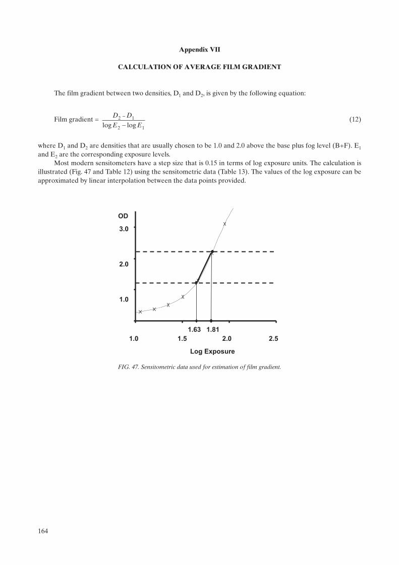
Appendix VII
CALCULATION OF AVERAGE FILM GRADIENT
The film gradient between two densities, D1 and D2, is given by the following equation:
Film gradient = (12)
where D1 and D2 are densities that are usually chosen to be 1.0 and 2.0 above the base plus fog level (B+F). E1
and E2 are the corresponding exposure levels.Most modern sensitometers have a step size that is 0.15 in terms of log exposure units. The calculation is
illustrated (Fig. 47 and Table 12) using the sensitometric data (Table 13). The values of the log exposure can be approximated by linear interpolation between the data points provided.
D D
E E2 1
2 1
-
-log log
1.0 1.5 2.0 2.5
Log Exposure
1.63 1.81
3.0
2.0
1.0
OD
FIG. 47. Sensitometric data used for estimation of film gradient.
164

TABLE 12. CALCULATION OF FILM GRADIENT
ODa Log exposure
B+Fb 0.22 —
D1c 1.22 Log E1
d = 1.63
D2 2.22 Log E2 = 1.81
Film gradient = (2.22–1.22)/(1.81–1.63)= 5.55
a OD: Optical density.b B+F: Base plus fog level.c D: Density.d E: Exposure level.
TABLE 13. SENSITOMETRIC DATA
Step Log exposure ODa
1 0.00 0.22
2 0.15 0.22
3 0.30 0.22
4 0.45 0.22
5 0.60 0.22
6 0.75 0.23
7 0.90 0.25
8 1.05 0.29
9 1.20 0.38
10 1.35 0.51
11 1.50 0.77
12 1.65 1.30
13 1.80 2.17
14 1.95 3.10
15 2.10 3.82
16 2.25 4.21
17 2.40 4.21
18 2.55 4.06
19 2.70 4.13
20 2.85 4.18
21 3.00 4.20
a OD: Optical density.
165

Appendix VIII
THE STANDARD BREAST
For testing purposes, the ‘standard breast’ is simulated by PMMA of thickness 45 ± 0.5 mm with a semicircular section with a radius of at least 100 mm or rectangular with dimensions of at least 150 mm × 100 mm [4, 28]. The attenuation is equivalent to a compressed breast of 53 mm thickness of which the central thickness is composed of 29% fibroglandular tissue and 71% fat tissue and this region is surrounded above and below by a layer of fat that is 5 mm thick [25].
166
REFERENCES
[1] WORLD HEALTH ORGANIZATION, IARC Handbooks of Cancer Prevention, Vol. 7, Breast Cancer Screening (INTERNATIONAL AGENCY FOR RESEARCH ON CANCER, Ed.), IARC Press, Lyons (2002).
[2] TABAR, L., et al., Mammography service screening and mortality in breast cancer patients: 20 year follow up before and after introduction of screening, Lancet 361 (2003) 1405–1410.
[3] AMERICAN COLLEGE OF RADIOLOGY, Mammography Quality Control Manual, American College of Radio-logy, Reston, VA (1999).
[4] EUROPEAN COMMISSION, European Guidelines for Quality Assurance in Mammography Screening, 4th edn, Europe against Cancer, Office for Official Publications of the European Communities, Luxembourg (2006).
[5] INTERNATIONAL ATOMIC ENERGY AGENCY, Control de Calidad en Mamografía, IAEA-TECDOC-1517, IAEA, Vienna (2006).
[6] SOCIEDAD ESPAÑOLA DE FÍSICA MÉDICA–SOCIEDAD ESPAÑOLA DE PROTECCIÓN RADIO-LÓGICA, Protocolo Español de Control de Calidad en Radiodiagnóstico (Aspectos Técnicos), 2nd edn, Edicomplet, Madrid (2002).
[7] PISANO, E.T., et al., Diagnostic Performance of Digital versus Film Mammography for Breast-Cancer Screening, N. Engl. J. Med. 353 (2005) 1–11.
[8] INTERNATIONAL ELECTROTECHNICAL COMMISSION, Medical Electrical Equipment: X Ray Tube Assem-blies for Medical Diagnosis — Characteristics of Focal Spots, Rep. IEC 60336, IEC, Geneva (2005).
[9] WORLD HEALTH ORGANIZATION, Quality Assurance in Diagnostic Radiology, WHO, Geneva (1982).[10] INTERNATIONAL ATOMIC ENERGY AGENCY, Applying Radiation Safety Standards in Diagnostic Radiology
and Interventional Procedures Using X Rays, Safety Reports Series No. 39, IAEA, Vienna (2006).[11] MOORES, B.M., HENNSHAW, E.T., WATKINSON, S.A., PEARCY, B.J., Practical Guide to Quality Assurance in
Medical Imaging, John Wiley & Sons, Chichester (1987).[12] McKINNERY, W.E.J., Radiographic Processing and Quality Control, JB Lippincott Co., Philadelphia, PA (1988).[13] INTERNATIONAL ELECTROTECHNICAL COMMISSION, Evaluation and Routine Testing in Medical Imaging
Departments, Part 2–1: Consistency Tests — Film Processors, Rep. IEC 61223-2-1, IEC, Geneva (1993).[14] HAUS, A.G. (Ed.), Advances in Film Processing Systems Technology and Quality Control in Medical Imaging,
Medical Physics Publishing, Madison, WI (2001).[15] AMERICAN ASSOCIATION OF PHYSICISTS IN MEDICINE, Equipment Requirements and Quality Control for
Mammography, Rep. 29, AAPM, New York (1990).[16] GRAY, J.E., “Mammographic quality control for the technologists and the medical physicist as consultant to the tech-
nologists”, Syllabus: A Categorical Course in Physics — Technical Aspects of Breast Imaging (HAUS, A.G., YAFFE, M.J., Eds), Radiological Society of North America (1992) 131–160.
[17] INTERNATIONAL ELECTROTECHNICAL COMMISSION, Evaluation and Routine Testing in Medical Imaging Departments, Part 2. 10 Constancy tests — X ray equipment for mammography, Rep. IEC 61223-2-10, IEC, Geneva (1999).
[18] GRAY, J.E., “Mammographic quality control for the technologists and the medical physicist as consultant to the tech-nologists”, Syllabus: A Categorical Course in Physics — Technical Aspects of Breast Imaging (HAUS, A.G., YAFFE, M.J., Eds), Radiological Society of North America (1994) 153–183.
[19] WIDMER, J.H., LILLIE, K.R., JASHULSKI, S.M., HAUS, A.G. (Eds), Identifying and Correcting Processing Arte-facts, Technical and Scientific Monograph No. 4, Kodak, Health Sciences, Rochester, NY (1994).
[20] INTERNATIONAL ELECTROTECHNICAL COMMISSION, Evaluation and Routine Testing in Medical Imaging Departments, Part 3–2: Acceptance Testing — Imaging Performance of Mammographic X-ray Equipment, Rep. 61223-3-2, edn 2.0, IEC, Geneva (2004).
[21] YOUNG, K.C., WALLIS, M.G., BLANKS, R.G., MOSS, S.M., Influence of number of views and mammographic film density on the detection of invasive cancers: Results from the NHS Breast Screening Programme, Br. J. Radiol. 70(1997) 482–488.
[22] BRITISH INSTITUTE OF RADIOLOGY, Assurance of Quality in the Diagnostic X Ray Department, QA Working Group of the Diagnostic Methods Committee of the BIR, London (1988).
[23] WAGNER, L.K., ARCHER, B.R., CERRA, F., On the measurement of half-value layer in film-screen mammography, Med. Phys. 17 (1990) 989–997.
[24] INTERNATIONAL ELECTROTECHNICAL COMMISSION, Medical Electrical Equipment, Part 2–45: Particular Requirements for the Safety of Mammographic X-ray Equipment and Mammographic Stereotactic Devices, Rep. IEC 60601-2-45, IEC, Geneva (1998).
[25] DANCE, D.R., SKINNER, C.L., YOUNG, K.C., BECKETT, J., KOTRE, C.J., Additional factors for the estimation of mean glandular breast dose using the UK mammographic dosimetry protocol, Phys. Med. Biol. 45 (2000) 3225–3240.
167

[26] WU, X., BARNES, G.T., TUCKER, D.M., Spectral dependance of glandular tissue dose in screen-film mammography, Radiology 179 (1991) 143–148.
[27] WU, X., GINGOLD, E.L., BARNES, G.T., TUCKER, D.M., Normalised average glandular tissue dose in molyb-denum target — rhodium filter and rhodium and rhodium — target rhodium filter mammography, Radiology 193(1994) 83–89.
[28] INTERNATIONAL ATOMIC ENERGY AGENCY, Dosimetry in Diagnostic Radiology: An International Code of Practice, Technical Reports Series No. 457, IAEA, Vienna (2007).
[29] INTERNATIONAL COMMISSION ON RADIATION UNITS AND MEASUREMENTS, Patient Dosimetry for X Ray Used in Medical Imaging, Rep. No. 74, ICRU, Bethesda, MD (2006).
[30] EASTMAN KODAK COMPANY, KODAK X-OMAT Processor, Service Bulletin No. 158, Eastman Kodak Company/Customer & Technical Services/Health Sciences Markets Division/Rochester, NY (1993).
[31] EASTMAN KODAK COMPANY, Processing Recommendations, Service Bulletin No. 30, Eastman Kodak Company/Health Group, Rochester, New York (2007), http://www.carestreamhealth.com/en/global/plugins/acrobat/en/health/support/tib3107.pdf
168

BIBLIOGRAPHY
AMERICAN ASSOCIATION OF PHYSICISTS IN MEDICINE, Equipment Requirements and Quality Control for Mammography, AAPM Rep. 29, AAPM, New York (1990).
AMERICAN COLLEGE OF RADIOLOGY, Mammography Quality Control Manual, ACR, Reston, VA (1999).
BRITISH INSTITUTE OF RADIOLOGY, Assurance of Quality in the Diagnostic X Ray Department, 2nd edn, QA Working Group of the Radiation Protection Committee of the BIR, London (2001).
DANCE, D.R., SKINNER, C.L., YOUNG, K.C., BECKETT, J., KOTRE, C.J., Additional factors for the estimation of mean glandular breast dose using the UK mammographic dosimetry protocol, Phys. Med. Biol. 45 (2000) 3225–3240.
EUROPEAN COMMISSION, European Guidelines for Quality Assurance in Mammography Screening, 4th edn, Europe against Cancer, Office for Official Publications of the European Communities, Luxembourg (2006).
GUNN, C., Radiographic Imaging: A Practical Approach, 3rd edn, Churchill Livingstone, Edinburgh (2002).
HAUS, A.G. (Ed.), Advances in Film Processing Systems Technology and Quality Control in Medical Imaging, Medical Physics Publishing, Madison, WI (2001).
INSTITUTE OF PHYSICS AND ENGINEERING IN MEDICINE, The Commissioning and Routine Testing of Mammographic X Ray Systems, IPEM Rep. 89, IPEM, York (2005).
LLOYD, P.J., Quality Assurance Workbook for Radiographers and Radiological Technologists, World Health Organization, Geneva (2001).
McCLELLAND, I.R., X Ray Equipment Maintenance and Repairs Book for Radiographers and Radiological Technologists, World Health Organization, Geneva (2004).
WIDMER, J.H., LILLIE, K.R., JASHULSKI, S.M., HAUS, A.G. (Eds), Identifying and Correcting Processing Artefacts, Technical and Scientific Monograph No. 4, Kodak, Health Sciences, Rochester, NY (1994).
169

.

Annex I
RADIOGRAPHER’S DATA COLLECTION SHEETS
List of data collection sheets in this annex:
6 Unit Information6.1 Visual inspection checklist6.2 Film storage6.3.1 Darkroom cleanliness6.3.2 Darkroom temperature, humidity & ventilation conditions6.3.3 White light leakage and safe lights6.3.4 Automatic processor developer temperature6.3.5 Sensitometry (2 sheets)6.3.5 X ray processing control chart6.3.6 Artefact detection6.3.7 Transition between emulsion numbers6.4.1 Cleaning of intensifying screens6.4.2 Screen film contact6.4.3 Uniformity of cassette sensitivity, attenuation and artefacts6.5.1 Automatic exposure control consistency6.5.1 X ray system AEC consistency chart6.5.2 AEC thickness compensation6.5.2 X ray system AEC thickness compensation chart6.6 Evaluation of image quality6.7 Film rejection rateAppendix III Automatic processor developer time, pH and replenishment rate, etc.
The electronic version of these data collection sheets can be found by accessing the IAEA web site at http://www-pub.iaea.org/MTCD/publications/PDF/Pub1381Files/Annex1_DataCollectionSheets_Radiographer.xls
171
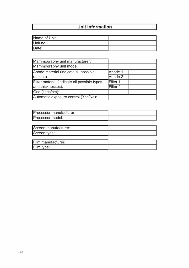
Name of :
Unit no.:
Date:
Mammography unit manufacturer:
Mammography unit model:
Anode 1
Anode 2
Filter 1
Filter 2
Grid (lines/cm):
Automatic exposure control (Yes/No):
Processor manufacturer:
Processor model:
Screen manufacturer:
Screen type:
Film manufacturer:
Film type:
Unit Information
Filter material (indicate all possible types
and thicknesses):
Anode material (indicate all possible
options)
Unit
172

Year
Yes No
1
2
3
4
5
6
7
8
9
10
11
12
13
14
15
16
6.1 Visual inspection checklist
Month
Parameter
The compression breast thickness scale (analog or digital) is
accurate and reproducible.
Free standing unit is mechanically stable.
Indicator lights working properly.
All locks and detents work properly.
All moving parts move smoothly, without obstructions to motion.
Image receptor and holder is free from vibrations during exposure.
Angulation indicators function properly
The face guard is in place
The automatic compression release following exposure functions
correctly.
The manual release of compression is possible when power fails.
The compression release override works properly.
The radiation shield for the operator is adequate.
Image receptor slides smoothly into holder assembly.
Image receptor is held securely by assembly in any orientation.
The compression plate is in good condition.
There are no sharp edges on the breast support or compression
paddle.
.
.
173

15 21
30 70
Month Temperature (ºC) Acceptable Humidity (%) Acceptable
Acceptable
<3
Comments:
Tolerance on inventory update (months)
Storage and utilization of film and chemicals:
Cassettes in vertical position (Y/N?)
Chronological order (Y/N?)
Inventory updated frequency (months)
6.2 Film storage
Room onditions:
TolerancesTemperature (ºC)
Humidity (%)
c
–
–
174

Year
Comment Floor Surfaces Processor
Comments:
29
30
31
21
22
23
24
25
26
27
28
15
16
17
18
5
6
19
20
9
10
11
12
13
14
7
8
6.3.1 Darkroom cleanliness
Month
Day
1
2
3
4
175

Month Temperature (ºC) Acceptable Humidity (%) Acceptable
Comments:
6.3.2 Darkroom temperature, humidity & ventilation conditions
Temperature and humidity
Ventilation system
TolerancesTemperature (ºC)
Humidity (%)
Fan working (Y/N?) AcceptableMonthPerceptible
odours (Y/N?)Acceptable
15–21
30–70
176

Month Power (W) Acceptable OD1 OD2 FSL
Comments:
* OD1 is density of section exposed to darkroom light
OD2 is density of section partly covered by black film
Significant white light leak present (Y/N?)
Room inspection for white light leakage
6.3.3 White light leakage and safe lights
Acceptable
Safe light bulb power (W)
Darkroom fogging (FSL)*Tolerances
� 15
� 0.05
Month AcceptableExtractors Ceilings OtherDoors Processor
Film pass
through box
-
177

Year
Processor display
temperature (ºC)
31
27
25
23
28
29
30
24
26
21
22
19
20
17
18
15
16
13
14
11
12
9
10
7
8
5
6
3
4
1
2
Acceptable
6.3.4. Automatic processor developer temperature
Month
Manufacturer value (ºC)
Tolerance (ºC) ±1.0ºC
Day Measured alue (ºC)
v
178

Step Day 1 Day 2 Day 3 Day 4 Day 5 Average
1
2
3
4
5
6
7
8
9
10
11
12
13
14
15
16
17
18
19
20
21
Step
OD
�0.25
�0.21
Comments:
6.3.5 Sensitometry
Establishing initial operating levels (IOLs)
Optical density (OD)
S (OD closest to but
not <1.2)
HD (OD closest to
but not <2.2)
Tolerance (B+F)
Acceptable
B+F
Acceptable
Achievable
DD
Initial Operating Levels
1
179

Parameter IOL
B+F
S
DD
HD
Measured Acceptable Measured Acceptable Measured Calculated Acceptable
1
2
3
4
5
6
7
8
9
10
11
12
13
14
15
16
17
18
19
20
21
22
23
24
25
26
27
28
29
30
31
Day
Tolerance
B+F S DD
�IOL + 0.02
IOL ± 0.10
IOL ± 0.10IOL ± 0.15
�IOL + 0.03
IOL ± 0.15
Optical ensity (OD)
Acceptable
Daily sensitometry
Achievable
d
180

181

Comments:
Date AcceptableOther
6.3.6 Artefact detection
Unacceptable artefacts present (Y/N?)
Rollers Chemicals Mechanical Other
Processor
Grid
182

Day 1 2 3 4 5 average 1 2 3 4 5 average
S
HD
DD
B+F
S DD B+F
Comments:
Brand
6.3.7 Transition between emulsion numbers
Difference between new and old
New initial operation levels
Old emulsion New emulsion
Date:
Old initial operation levels
Emulsion number
Old emulsion New emulsion
Model
183

Year
Week
Damaged?
(Y/N)
Damaged?
(Y/N)
1
Clean?
(Y/N)
Damaged?
(Y/N)
2
Clean?
(Y/N)
6.4.1 Cleaning of intensifying screens
Screen ID
3 4
Month
Clean?
(Y/N)
Damaged?
(Y/N)
Clean?
(Y/N)
184

Month Year
Screen ID
Comments:
6.4.2 Screen film contact
Are there blackening areas?
Chest wall Other sides
Tolerance <2 mm Tolerance < mm5
<2 mm <2 mm <5 mm <5 mmAcceptable Acceptable
185
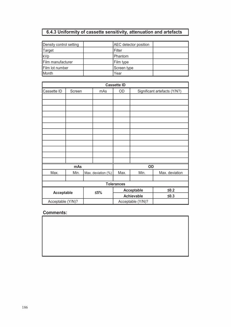
Cassette ID mAs OD
ax
Comments:
�0.2
�0.3
Acceptable (Y/N)?
Acceptable
Achievable
6.4.3 Uniformity of cassette sensitivity, attenuation and artefacts
Phantom
Tolerances
Acceptable (Y/N)?
Film manufacturer
Acceptable �5%
Film lot number
Month
mAs
Density control setting
Target Filter
kVp
AEC detector position
Significant artefacts (Y/N?)
Film type
Cassette ID
Screen type
Screen
Year
OD
M . Min. Max. deviation (%) Max. Min. Max. deviation
186

Date Measured Acceptable Displayed Acceptable Y/N Acceptable�1�
2
�
3�
4�
5�
6�
7�
8�
9�
10�
11�
12�
13�
14�
15�
16�
17�
18�
19�
20�
21�
22�
23�
24�
25�
26�
27�
28�
29�
30�
31�
OD�
mAs�
Comments:�
Cassette ID�
ODtarget ± 0.20ODtarget ± 0.15�
±10% of baseline mAs�
Achievable Acceptable�
Tolerance�
OD mAs�
Filter�
Phantom
Artefacts�
Baseline mAs�
Year
100
6.5.1 Automatic exposure control
Density control setting�
kVp�
Film type�
45 mm PMMA�
AEC detector position�
Target�
consist�ncy�
187
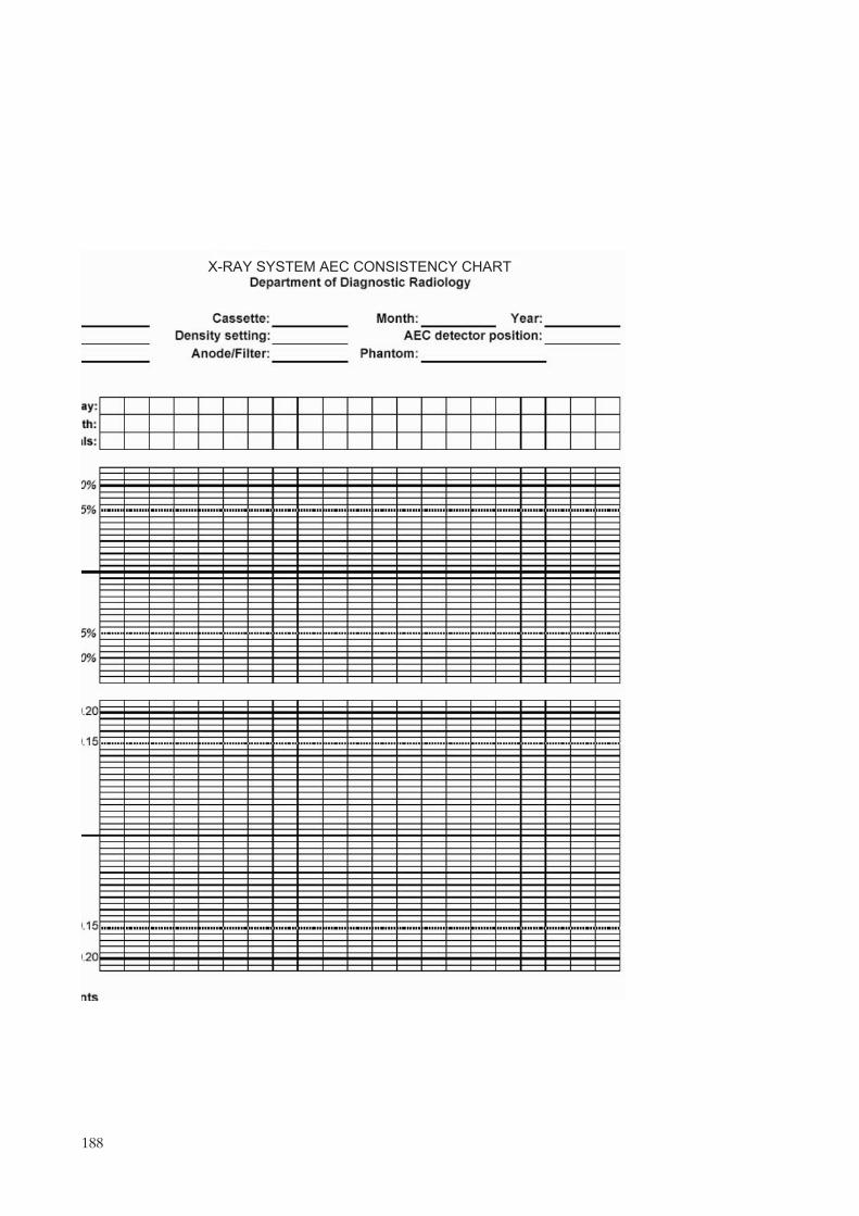
��������������� ������������
188
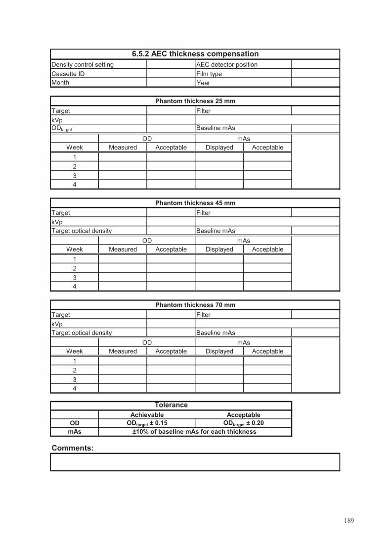
Week Measured Acceptable Displayed Acceptable
1
2
3
4
Week Measured Acceptable Displayed Acceptable
1
2
3
4
Week Measured Acceptable Displayed Acceptable
1
2
3
4
OD
mAs
Comments:
Cassette ID
Baseline mAs
Film type
ODtarget
Phantom thickness 25 mm
Month
kVp
Phantom thickness 45 mm
kVp
Target
OD
kVp
Target optical density Baseline mAs
Tolerance
ODtarget ± 0.15
mAs
±10% of baseline mAs for each thickness
Target optical density Baseline mAs
Achievable Acceptable
OD mAs
ODtarget ± 0.20
Filter
6.5.2 AEC thickness compensation
OD mAs
Density control setting AEC detector position
Target Filter
Phantom thickness 70 mm
Target Filter
Year
189
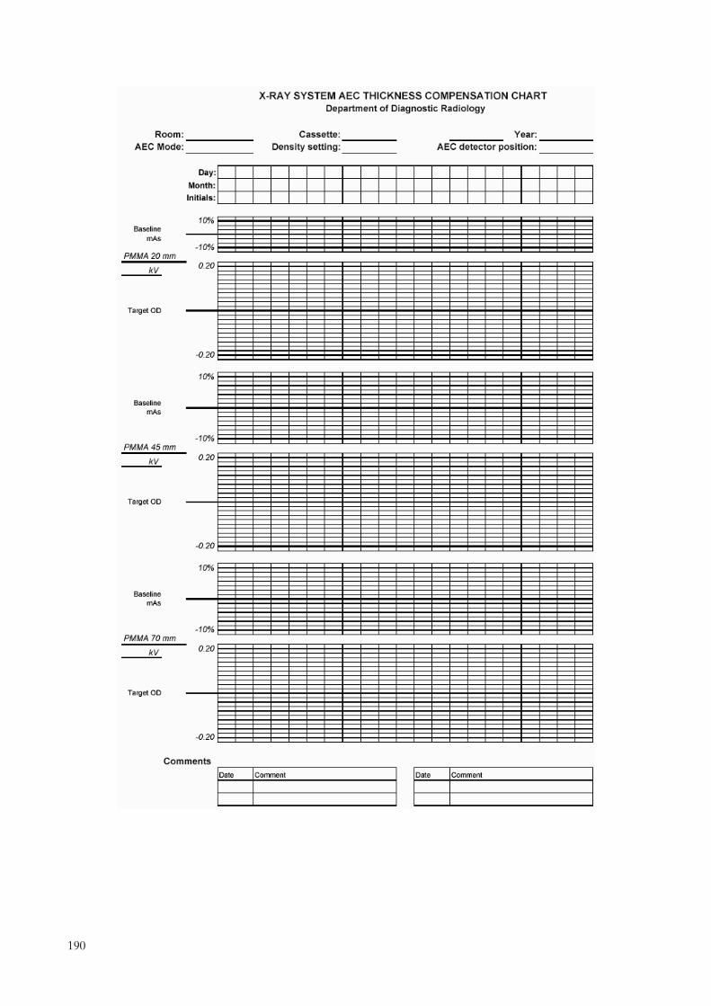
190
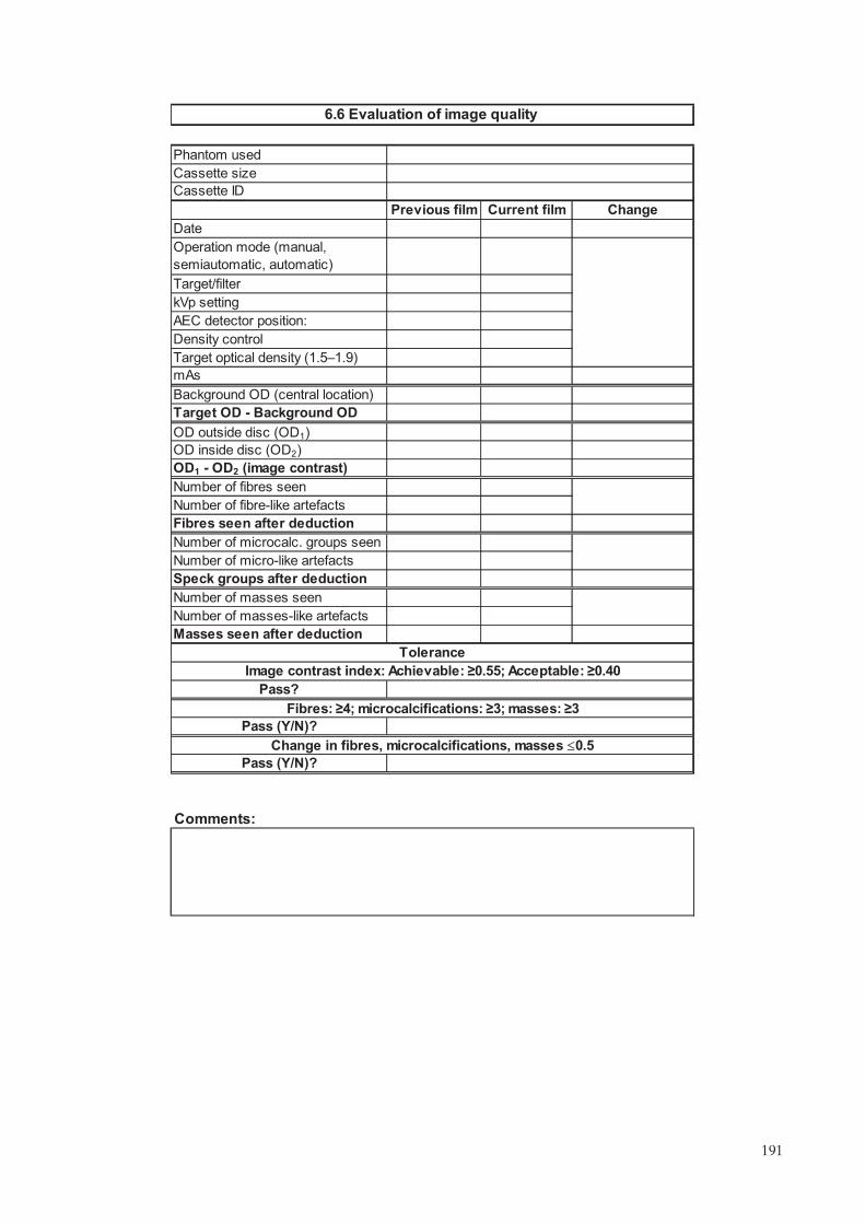
Comments:
OD inside disc (OD2)
Number of micro-like artefacts
OD outside disc (OD1)
OD1 - OD2 (image contrast)
Pass (Y/N)?
Fibres: �4; microcalcifications: �3; masses: �3
Pass (Y/N)?
Change in fibres, microcalcifications, masses �0.5
Tolerance
Image contrast index: Achievable: �0.55; Acceptable: �0.40
Pass?
Number of masses seen
Masses seen after deduction
Number of masses-like artefacts
Speck groups after deduction
Number of microcalc. groups seen
Number of fibres seen
Number of fibre-like artefacts
Fibres seen after deduction
Target OD - Background OD
mAs
Background OD (central location)
Density control
Target optical density (1.5�1.9)
kVp setting
AEC detector position:
Target/filter
Operation mode (manual,
semiautomatic, automatic)
Previous film Current film Change
Date
Cassette ID
6.6 Evaluation of image quality
Phantom used
Cassette size
191

from to
Left Right Left Right Left Right
ling
�8%
�3%
Comments:
6.7 Film rejection rate
Total studiesTotal of films used for the period
Acceptable
Achievable
Tolerance
*Reject rate (%) = 100 * Total reject films / (Total of films used for period - QC films)
QC films:
Frequency of rejection cause
MLO
Acceptable
Total
Others:
CC
Person responsible
Period of analysis
Technical factors:
Cause
Darkroom and processor
Total of rejected films
Other
Rejection rate (%)*:
l
Positioning
Motion
Incorrect labe
Technique factors
Artefacts
Static
Fog
Light and dark films
Artefacts
192

±3%
±3%
±0.004
±0.5
±0.5
±10%
±10%
±10%
±10%
±10%
±10%
Comments:
Trial 1
Measured
Manufacturer
Manufacturer
pH fixer
AcceptableManufacturer
Total processing time (s)
Acceptable
Trial 3
Developer time
pH
Developer replenishment rate
(volume)
Developer time (s)
pH developer
Tolerance Acceptable
Tolerance
Appendix III Automatic processor developer time, pH and replenishment
rate, etc.
Measured
Measured Tolerance Acceptable
Tolerance Acceptable
Measured Tolerance
Measured
Trial 2
Trial 3
Specific gravityManufacturer
Measured value
Fixer replenishment rate (volume)Manufacturer
Trial 1
Trial 2
100value ermanufactur
value measuredvalue ermanufactur(%)iation varVolume ×−=
value
value
value
value
value
193

.

Annex II
MEDICAL PHYSICIST’S DATA COLLECTION SHEETS
List of data collection sheets in this annex:
7 Mammography equipment evaluation (2 sheets)7 Mammography equipment information7.1 Unit assembly evaluation7.2.1 Sensitometry (2 sheets)7.3.1 Radiation leakage7.3.2 Accuracy and repeatability of kVp7.3.3 Half-value layer (HVL)7.3.4 Output repeatability and linearity7.3.5 Compression7.3.6 Evaluation of the automatic exposure control (3 sheets)7.4 Collimation system7.5 Image viewing conditions7.6.1 Evaluation of image quality7.6.2 System spatial resolution7.7.1 Incident kerma at entrance surface of the phantom7.7.2 Mean glandular dose (DG)
The electronic version of these data collection sheets can be found by accessing the IAEA web site at http://www-pub.iaea.org/MTCD/publications/PDF/Pub1381Files/Annex2_DataCollectionSheets_MedicalPhysicist.xls
195

Report date
Survey date
X ray unit manufacturer
Date of installation Room ID
Medical hysicist Signature
Radiographer
Type of inspection*
(*Annual; semi-annual; monthly)
UNIT ASSEMBLY EVALUATION
DARKROOM AND SENSITOMETRY
Sensitometry
Darkroom radiation level < 20μGy/week
RADIOLOGICAL EQUIPMENT
Radiation leakage < 1 mGy/h at 1 m
Accuracy and repeatability of the tube kV
Accuracy: �5%
Repeatability: Difference �5% or COV �2%
Half value ayer
HVL is within acceptable lower and upper limits at all kVp values tested
Output: Repeatability and linearity
Repeatability: Difference �5% or COV� 5%
Linearity: ±10%
Normalized output value: >30 μGy/mAs at 1 m, 28 kV, Mo/Mo
COMPRESSION
Compression force: Power Comp: 150 N 200 N; Manual Comp: <300 N
Compression force: Accuracy � ±20 N
Compression thickness accuracy: �5mm
AUTOMATIC EXPOSURE CONTROL
Density Control in "Normal" or "0" position provides ODtarget ± 0.20
Repeatability of the automatic exposure control: mAs: COV � 5%
Compensation for different kV and thicknesses (and target/filter combination):
Acceptable: Maximum deviation from OD target � 0.2;
Achievable: Maximum deviation from OD target � 0.15
Density control setting: difference per step: %mAs change:
ΔOD :
Exposure time 45 mm thick PMMA test
Contact mammography: Achievable: t �
Acceptable: t �
Magnification mammography: Achievable: t �
Acceptable: t �
Pass
Mammography equipment evaluation
Site
1.5s
2s
2s
3s
Model
12%–15%
0.1–0.2
–
p
l-
196

COLLIMATION SYSTEM
Light field/radiation field coincidence: �1% of FFD on any side
Radiation field/image receptor coincidence
Acceptable: Chest side 0 to 5 mm; ≤2% of FFD for other three sides
Achievable: Chest side 0 to ≤ 5 mm; �0 for other three sides
Compression paddle/breast support alignment: �+1% of FFD
IMAGE VIEWING CONDITIONS
Luminance of the viewboxes: >3000 cd/m2 (nit)
Viewboxes homogeneity and colour
Single viewbox: <30%
Between viewboxes: <15%
Ambient interpretation room illumination: Achievable: �10 lux; Acceptable: �50 lux
IMAGE QUALITY
Phantom image quality evaluation (ACR)
Background optical density: ODtarget ± 0.2
Optical density difference between disk and background
Acceptable: ≥0.40 OD
Achievable: ≥0.55 OD
Phantom score
Acceptable: Fibre score: ≥4
Speck score: 3
Mass score: ≥3
Change in score for each group: � 0.5
System spatial resolution
Achievable: ≥15 lp/mm
Acceptable: ≥11 lp/mm
DOSIMETRY
Mean glandular dose (DG)
Achievable: DG � 2.0 mGy;
Acceptable: DG � 2.5 mGy
Mammography quipment valuation (cont.)
≤
≥
e e
197
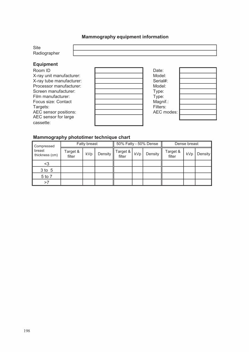
Site
Radiographer
Equipment
Room ID Date:
X-ray unit manufacturer: Model:
X-ray tube manufacturer: Serial#:
Processor manufacturer: Model:
Screen manufacturer: Type:
Film manufacturer: Type:
Focus size: Contact Magnif.:
Targets: Filters:
AEC sensor positions: AEC modes:AEC sensor for large
cassette:
Mammography phototimer technique chart
>7
5 to 7
3 to 5
kVp DensityTarget &
ilter
Compressed
<3
Fatty breast 50% Fatty - 50% Dense
Target & kVp Density
Target &
Dense breast
DensitykVpbreast
thickness (cm) filter filter f
Mammography equipment information
198

1 Free standing unit is mechanically stable.
2 Indicator lights work properly.
3 All moving parts move smoothly, without obstructions to motion.
4 All locks and detents work properly.
5 Angulation indicators function properly.
6 Image receptor and holder is free from vibrations during exposure.
7 Image receptor slides smoothly into holder assembly.
8 Image receptor is held securely by assembly in any orientation.
9 The compression plate is in good condition.
10 The compression breast thickness scale (analog or digital) is accurate
and reproducible.
11 The automatic compression release following exposure functions
correctly.
12 The manual release of compression is possible when power fails.
13 The compression release override works properly.
14 The radiation shield for the operator is adequate
15 There are no sharp edges on the breast support or compression
paddle.
16 The face guard is in place.
17 Confirm that appropriate, current operator technique control charts are
posted.
Unit assembly acceptable (Y/N)?
Comments:
Pass
(Y/N/NA)
7.1 Unit assembly evaluation
Parameter
199

Step log E Day 1 Day 2 Day 3 Day 4 Day 5 Average
1 0.00
2 0.15
3 0.30
4 0.45
5 0.60
6 0.75
7 0.90
8 1.05
9 1.20
10 1.35
11 1.50
12 1.65
13 1.80
14 1.95
15 2.10
16 2.25
17 2.40
18 2.55
19 2.70
20 2.85
21 3.00
Step
OD
�0.25
�0.21
log E1 log E2
Comments:
Acceptable (Y/N)?
Gradient estimation
D1 = 1.0+ (B+F) D2 = 2.0+(B+F) Gradient
Log E1 and log E2 is obtained by linear interpolation of data points near relevant density steps
Tolerance (B+F)Acceptable
Achievable
Optical density (OD)
7.2.1 Sensitometry
Establishing initial operating levels (IOLs)
Initial Operating Levels
S (OD closest to but
not < 1.2)
HD (OD closest to
but not < 2.2)DD B+F
200
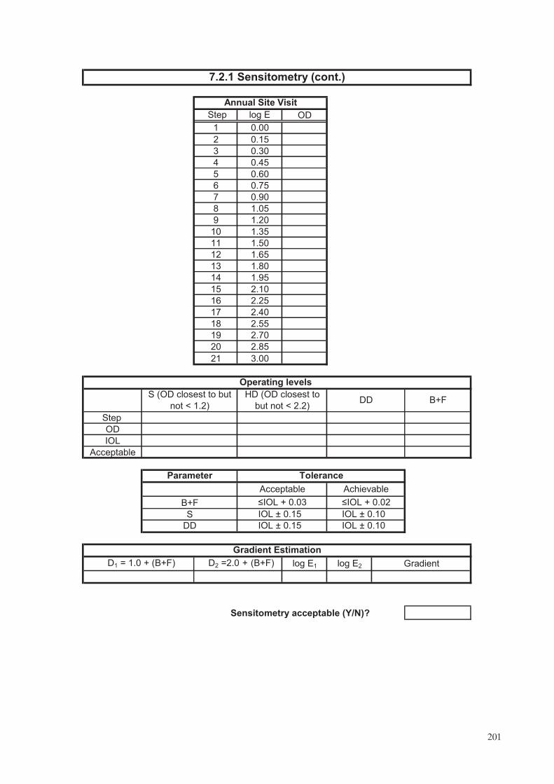
Step log E OD
1 0.00
2 0.15
3 0.30
4 0.45
5 0.60
6 0.75
7 0.90
8 1.05
9 1.20
10 1.35
11 1.50
12 1.65
13 1.80
14 1.95
15 2.10
16 2.25
17 2.40
18 2.55
19 2.70
20 2.85
21 3.00
Step
OD
IOL
Acceptable
log E1 log E2
Sensitometry acceptable (Y/N)?
�IOL + 0.03 �IOL + 0.02
IOL ± 0.15 IOL ± 0.10
DD
Gradient Estimation
D1 = 1.0 + (B+F) D2 =2.0 + (B+F) Gradient
IOL ± 0.15 IOL ± 0.10
7.2.1 Sensitometry (cont.)
Annual Site Visit
Operating levels
S (OD closest to but
not < 1.2)
HD (OD closest to
but not < 2.2)B+F
Tolerance
Acceptable Achievable
DD
B+F
S
Parameter
201

Dosimetry system used
Comments:
Tolerance
<1 mGy/h at 1 m
Pass (Y/N)?
4
3
2
Reading
(mGy) K0 (mGy)
kerma rate at 1m
(mGy/h)Point
Pressure (mbar) Temperature (ºC) Pressure and
factor (kTP)
Measurements
1
Focal spot-chamber
distance, d (m)
7.3.1 Radiation eakage
Energy correction factor (Nmammo) 1.00
1.00mAs0 used: 50 mAsmax 14400
RFRFK�
2
0
0
maxRF dK
mAs
mAsK ××=•
temperature correction
l
202

Comments:
Tolerance
Repeatability: acceptable?
Nominal kVp - <kVp>
Pass (Y/N)?Repeatability: Difference � 5% or
Accuracy (%)
Accuracy: ±5%
7.3.2 Accuracy and repeatability of kVp
Repeatability: difference (%)
Mean kVp <kVp>
Repeatability: COV (%)
kVp5
Standard deviation (SD)
kVp4
Additional measurements (if needed)
kVp3
kVp2
Measured kVp values
kVp1
mA setting
mAs setting
Focal spot (large/small)
Meter setting:
kVp meter used:
Nominal kVp setting
203

Anode
Filter
Parameter, C
mAs setting:
0.2 mm of added aluminium, M1
0.3 mm of added aluminium, M2
0.4 mm of added aluminium, M3
0.5 mm of added aluminium, M4
0.6 mm of added aluminium, M5
ta
tb
Ma
Mb
Calculated HVL (mm Al)
Comments:
Dosimetry system used
Acceptable (HVL)
Maximum allowed HVL (mm Al)
Tolerance
Minimum allowed HVL (mm Al)
Record thicknesses (ta<tb) and air
kerma or exposure values that
bracket k0/2: (Ka>Kb)
Repeat no aluminium filtration, M0
Average no aluminium filtration, M0
7.3.3 Half value layer
Air kerma or exposure measurements:
Units (mGy, mR)
tb ln[2Ma/Mo] - ta ln[2Mb/Mo]Calculated HVL =
Nominal kVp setting
No aluminium filtration, M0
All HVLs acceptable
Minimum allowed HVL (mm Al):
Maximum allowed HVL (mm Al):
where C = 0.12 for Mo/Mo, 0.19 for Mo/Rh, 0.22 for Rh/Rh, and 0.30 for W/Rh
kVp/100 + 0.03 (in mm Al)
(kVp/100) + C (in mm Al)
ln[Ka/Kb]
-
204

R1
R2
R3
R4
R5
R1
R2
R1
R2
L1
L2
Comments:
Linearity:<±10%
Normalized output @ 28 kV with
Mo/Mo: >30 μGy/mAs
Output (Y3)
Tolerance
Repeatability @ 28 kVp:
Difference � 5% or COV � 5%
Normalized output (μGy/mAs at 1m)
Linearity
Average value
Energy correction factor (Nmammo)
P0 (mbar)T0 (ºC)
Average value
Mo
MoFilter
Focus-detector distance (cm)
Large
Output (Y2)
Nominal kVp setting 28
Pressure and temperature correction factor (k TP)* (for auto correction = 1) 1.00
P(mbar)
7.3.4 Output repeatability and linearityDosimetry system used
40mAs1=
Temp (ºC)
mAs3= 120
80mAs2=
Repeatability: Difference (%)
Average value
Standard deviation
Output (Y1)
Units (enter "mGy" or "mR")
Repeatability: COV (%)
Focus size
Anode
( )( ) P
P
T2.273
T2.273k 0
0TP +
+=
205

Compression mode
Compression mode
Compression mode (powered or manual)
Maximum force measured: Power compression: ; Manual compression:<300 N
Comments:
Imaging mode
Manual
Magnification
Contact Magnification
Maximum force measured
7.3.5 Compression
Displayed value accuracy
Maximum force measured
Displayed force value
Powered
Displayed force value
Tolerance
Displayed value accuracy
PMMA thickness (mm)
Thickness measurements
Contact
20 70
Imaging mode
Does breast thickness indication depend on degree of compression (Y/N)?
±20 N
45
Displayed thickness accuracy ≤5 mm
Measured thickness (mm)
Displayed thickness (mm)
45 70 20
Displayed accuracy (mm)
Acceptable (Y/N)?
Acceptable (Y/N)?
Displayed force accuracy
Acceptable (Y/N)?
150–200 N
206

Target filter:
OD = ODtarget ± 0.2
Comments:
Density control
Small Cassette ID
AEC sensor position
0 (N) ODtarget
Large Cassette ID
COV (%)
2.0 s
Time (s) (measured)
Tolerances
3.0 s
mAs
mA
COV � 5%
Contact modeMagnification
Small cassette Large cassette
Exposure time 45 mm thick test
Achievable
Achievable (Y/N)?
1.5 s
Time (s) (calculated)
Acceptable
Acceptable (Y/N)?
AEC Repeatability (45 mm PMMA)
Automatic exposure mode (at clinical conditions)
mAs4
Mean (mAs)
OD (last image)
2.0 s
Tolerances
7.3.6 Evaluation of automatic exposure control (AEC)
kVp:
Large cassetteMagnification
Different sensor for large and small cassette (Y/N)?
Small cassette
Contact mode
mAs1
mAs2
mAs3
(1.5–1.9)
207

Comments:
Acceptable
Achievable
Tolerance
Acceptable: Maximum deviation from ODtarget � 0.2
Achievable: Maximum deviation from ODtarget � 0.15
Small cassette Large cassette Magnification
70
60
45
40
Deviation
20
PMMA hickness (mm) Image no. Target filter kV mAs OD
Magnification mode Small cassetteDensity control AEC Sensor position
70
60
40
45
20
Contact mode Large cassette(NB: If AEC sensor is common to both image receptor sizes then 45 mm phantom thickness only is required)
Density control AEC sensor position
60
70
20
45
40
Compensation for different thicknesses (and kVp and target/filter combination)
ODtarget
AEC Sensor position
7.3.6 Evaluation of automatic exposure control (AEC) (cont.)
Contact mode Small cassette
Density control
t
DeviationPMMA hickness (mm) Image no. Target filter kV mAs ODt
DeviationPMMA hickness (mm) Image no. Target filter kV mAs ODt
208

0 ("N")
(NB: If AEC sensor is common to both image receptor sizes then small cassette only is required)
0 ("N")
7.3.6 Evaluation of automatic exposure control (AEC) (cont.)
Density control setting: difference per step
Phantom Thickness
Density selector setting
Contact mode
Contact mode:
45 mm PMMA
Image No. mAs ODDensity selector setting
Phantom Thickness Target/filter kV
ΔmAs (%) ΔOD
Small cassette45 mm PMMA Target/filter kV
Image No. mAs OD ΔmAs (%) ΔOD
Large cassette
Tolerance
Acceptable: ΔmAs (%): ; ΔOD : 0.1 - 0.2
Small cassette
Large cassette
12–15%
209

Focus-film distance (FFD): mm
Diff. paddle edge & film (mm)
Differences as % of FFD (mm)
Comments:
X-ray field alignment (Pass (Y/N)?)
Light field alignment (Pass (Y/N)?)
Pass (Y/N)?
receptor: (Note:+ve deviation indicates paddle extends beyond image receptor)
Acceptable: Not visible at the chest wall & between 0 to �1% of FFD
Tolerance
Nipple edge deviation (mm)
Alignment of chest wall edge of compression paddle and image
7.4 Collimation system
Deviation as % of FFD
% of FFD (retain sign)
% of FFD (retain sign)
Anterior edge deviation (mm)
Tolerance
Acceptable: Chest edge 0 to ≤5 mm; �2% of FFD for other three edges
Achievable: Chest edge 0 to ≤5 mm; >0 for other three edges
Pass?Chest edge
Other edges
% of FFD (retain sign)
Chest edge deviation (mm)
(Note: +ve deviation indicates X ray field extends beyond image receptor)
Deviation as % of FFD
Coincidence between X ray field and image receptor:
Tolerance
Achievable: �1% of FFD on any side
Chest wall edge deviation (mm)
Deviation as % of FFD
Deviation as % of FFD
Right edge deviation (mm)
Left edge deviation (mm)
Collimator (cm x cm)
Coincidence between X ray field and light field:(Note: +ve deviation indicates X ray field extends beyond light field)
Anode material
Left edge deviation (mm)
Right edge deviation (mm)
Compression paddle alignment (Pass (Y/N)?)
Pass (Y/N)?
210

Comments:
Achievable (Y/N)?
Acceptable (Y/N)?
Acceptable (Y/N)?
Luminance uniformity within each panel in viewbox < 30%
Viewbox central luminance for each panel > 3000 cd/m2 (nit)
Pass (Y/N)?
Viewbox information Location
Functioning masks
Fluorescent tube age
7.5 Image viewing conditions
Adjacent viewbox panel
identification
Tolerances
Acceptable (Y/N)?
Luminance homogeneity
Dirt & marks present
Panel colour difference?
Maximum
deviation in
luminance (%)
Fluorescent tube type
Bottom left corner
Bottom right corner
Ambient illumination (viewboxes turned off)
Viewbox location
Maximum deviation between
panels in viewbox or adjacent
panels (%)
Luminance uniformity between panels in viewbox <15%
Pass (Y/N)?
Tolerance
Illumination (lux)
Top left corner
Top right corner
Average viewbox central luminance for all panels Lmean =
Centre (Lc)
Luminance uniformity Achievable: �10 lux; Acceptable: �50 lux
Acceptable (Y/N)?
Acceptable (Y/N)?
mean
meanc
L
LL100
−
c
cdisc
L
LL100
−
mean
meanc
L
LL100
−
c
cdisc
L
LL100
−
211
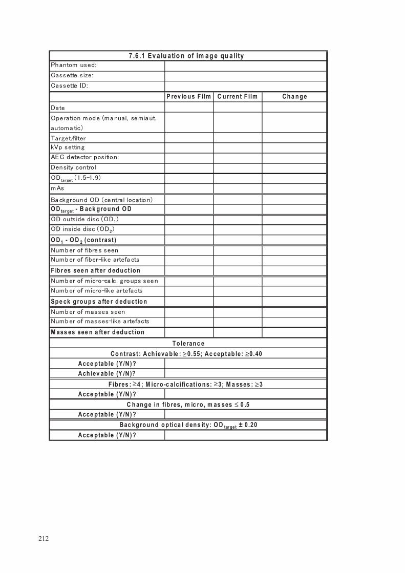
Sp e ck g ro u p s a fte r d ed u ct io n
O D 1 - O D 2 ( co n t rast )
P rev io u s F ilm
7 .6 .1 Ev a lu a tio n of im a g e qu a lity
C u rren t F ilm Ch a n g e
Ach iev ab le (Y /N )?
C h an g e in fib res, m ic ro , m as ses ≤ 0 .5
O D tar get - B ack g ro u n d O D
M ass es see n a ft er d ed u ct io n
F ib r es see n a ft er d ed u ct io n
Acce p tab le ( Y/N ) ?
F ib res : 4 ; M icro -c alci ficat io n s: 3; M a sses : 3Acce p tab le ( Y/N ) ?
Acce p tab le ( Y/N ) ?Bac kg ro u n d o p tica l d en s it y: O D tar ge t ± 0.20
Co n t rast : Ach ieva b le : 0 .55; Ac cep t ab le: 0 .40Acce p tab le ( Y/N ) ?
T o leran c e
≤≤≤
≤ ≤
212

Comments:
7.6.2 System spatial resolution
ray tube manufacturer
(if the film box is new)
Nominal focal spot size, fnom
Nominal kVp setting
Target material
Nominal mA setting
Density control setting
Magnification factor Contact
mAs
PMMA (mm)
bars ⊥ to A-C axis
Tolerance
Limiting
resolution
bars // to A-C axis
Achievable: �15 lp/mm in both directions; Acceptable: �11 lp/mm in both directions
Acceptable
Acceptable (Y/N)?
Achievable (Y/N)?
Achievable bars // to A-C axis
bars ⊥ to A-C axisAcceptable
Achievable
X Model no.
Emulsion no.
213
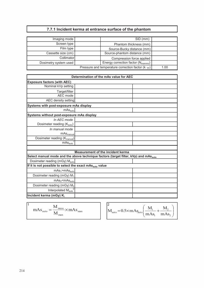
21
Incident kerma (mGy) Ki
Systems with post-exposure mAs display
AEC density setting
Dosimeter reading (mGy) M1
Exposure factors (with AEC)
Dosimeter reading (Kauto)
In manual mode
Dosimeter reading (mGy) M2
Nominal kVp setting
If it is not possible to select the exact mAsauto value
Measurement of the incident kerma
Select manual mode and the above technique factors (target filter, kVp) and mAsauto
Dosimeter reading (mGy) Mauto
Interpolated Mauto2
Determination of the mAs value for AEC
Collimator
Energy correction factor (Nmammo)
7.7.1 Incident kerma at entrance surface of the phantom
Phantom thickness (mm)
Imaging mode SID (mm)
Screen type
mAsauto
Target/filter
AEC mode
Pressure and emperature correction factor (k TP)
Source-Bucky distance (mm)Film type
Source-phantom distance (mm)
Compression force applied
1.00
Cassette size (cm)
mAsmanual
Dosimetry system used
In AEC modeSystems without post-exposure mAs display
mAsauto1
Dosimeter reading (Kmanual)
mAs1>mAsauto
mAs2<mAsauto
mAs
M
mAs
MmAs5.0M
2
2
1
1
autoauto ���
����
�+×=man
man
meas
automAs
M
MmAs ×=
t
214

Comments:
Measured HVL (mm Al):
DG (mGy)
Acceptable (Y/N)?
Incident kerma (mGy) Ki
Target/filter
HVL Product of g53 and c53 Target/filter s factors
0.40 0.218 Rh/Al
1.000
1.017
Mo/Mo
Mo/Rh0.35 0.196
1.044
0.55 0.297
0.30 0.172
W/Rh
1.0610.45 0.242 Rh/Rh
7.7.2 Mean glandular dose (DG)
Tolerance
Achievable: DG �2.0 mGy; Acceptable: D G �2.5 mGy
Achievable (Y/N)?
Product of g53 and c53
s factor
0.60 0.321
0.50 0.269 1.042
215

.

GLOSSARY
absorbed dose. The amount of energy per unit mass deposited in a medium. The SI unit of absorbed dose is the gray (Gy) representing 1 J/kg.
air kerma. The energy deposited per unit mass in air. The unit used to measure air kerma is the gray (Gy). For X rays with energies less than 300 kiloelectronvolts (keV), the magnitude of air kerma and absorbed dose in air are equivalent.
artefact. Any structure or pattern visible in the image that is not part of the object being imaged.
automatic exposure control (AEC) systems.
Fully automatic AEC. A device designed to determine the spectrum (target material, filtration material and kVp) and/or the exposure (mAs) needed to produce an adequately penetrated X ray image. This is typically done by sampling the X ray intensity after it passes through the patient and image receptor.
Automatic exposure time (phototiming). The beam quality parameters are selected manually and the exposure time is controlled automatically.
cassette. A light tight case usually made of thin, low X ray absorption plastic, that houses a film whose emulsion is, or whose emulsions are, in close contact with an intensifying screen(s).
coefficient of variation (COV). COV = x/x–, where x– is the mean of a set of measurements xi, and x is their
standard deviation.
compression device. A plastic paddle used to flatten and immobilize the breast. Compression helps reduce motion blurring in the breast, separates structures within the breast, and decreases the thickness of breast tissue. This minimizes the amount of radiation required and the amount of scattered radiation reaching the image receptor. Ideally, the compression device is made of rigid, thin plastic and has a flat bottom surface that is parallel to the plane of the image receptor and with edges perpendicular to the plane of the image receptor to assist in moving breast tissue away from the chest wall and into the field of view.
control chart. A graphical means of displaying data in which the variable of interest is plotted on the vertical axis as a function of time on the horizontal axis. The control chart allows for easy and rapid review of the data to determine whether the process is within the desired control limits (‘in control’).
control limit. The upper and lower values indicating that the process is ‘out of control’ and requiring that corrective action be taken. It is prudent to immediately repeat the measurement to verify that the system is ‘out of control’ before taking corrective action. If the repeated measurement is ‘out of control’, then corrective action is required immediately (or in some cases within 30 days). Synonym for ‘action limit’.
craniocaudal (CC) view. One of two routine views for mammography. The image receptor is placed caudal to (below) the breast and the vertical X ray beam is directed from cranial to caudal (downward) through the breast.
Dmax, Dmin. The maximum and minimum optical density on a film. Dmax is the darkest area of the film, where the highest exposure of X rays occurs. Dmin is the base plus fog optical density of the film.
densitometer. An instrument for measuring the optical density or degree of blackening of film.
density difference (DD). The difference in optical density between the high density and the speed index. This provides an index of contrast in the mammography film.
217

detents. Mechanical settings that limit or prevent the motion, rotation or exposure of an X ray tube, cassette assembly or image receptor system.
diagnostic mammography. Mammography performed on patients who, by virtue of symptoms, physical findings or a prior screening mammography examination, are considered to have some likelihood of having breast cancer.
dose. See absorbed dose.
dosimeter. Equipment which uses ionization chambers and/or semiconductor detectors for the measurement of air kerma, in the beam of an X ray machine used for mammography examinations.
exposure. The act of initiating and producing X radiation from an X ray unit.
film reciprocity law failure. Refers to the loss of film speed as exposure time increases. This results in a loss of expected film density and is particularly noticeable in mammography for exposure times in excess of 2 s.
focal film distance (FFD). The distance from the focal spot to the film.
focal spot. The area of the target or anode that is bombarded by electrons from the cathode of the X ray tube to produce X rays. The smaller the focal spot, the better the limiting spatial resolution of the X ray system, especially in magnification mammography.
fog. The unwanted signal added to an image by the exposure of the image receptor to light, radiation or heat between patient exposures.
FSL. Fog produced on the film due to the safety light.
grid. A set of thin, closely spaced strips of highly attenuating material, such as lead, interspaced by a radiolucent support material, such as carbon fibre. In mammography, the grid is placed between the breast and image receptor to reduce scattered radiation reaching the image receptor. Scattered radiation reduces image contrast in mammography and limits the detection of low contrast structures such as fibres and masses. Grids improve the contrast of radiographic images at the price of increased dose to the patient.
half-value layer (HVL). The thickness of a specified substance which, when introduced into the path of a beam of radiation, reduces the exposure rate by one half. HVL is a measure of beam quality and is usually specified in millimetres of aluminium for diagnostic X ray equipment. The higher the HVL, the more penetrating the X ray beam.
illuminance. A photometric quantity describing the light intensity per unit area falling on a surface. The SI unit for illuminance is lux (lx), candela–steradians per square metre.
image receptor. A device that detects and records the distribution of X rays to form an image.
IOL. Initial operating level.
kilovoltage, peak (kVp). The maximum value of the potential difference (kV) between anode and cathode in an X ray tube.
linearity. System response where the output increases in direct proportion to the input signal.
luminance. A photometric quantity describing the light power per unit area per unit solid angle emitted by a light source. The SI unit for luminance is candelas per square metre (cd/m2) (also known as ‘nit’).
218
mean glandular dose (MGD). The energy deposited per unit mass of fibroglandular tissue (the most radiosen-sitive tissue in the breast) averaged over all the fibroglandular tissue in the breast. The MGD is calculated from values of entrance air kerma, the X ray beam quality (half-value layer), and compressed breast thickness.
mediolateral oblique view (MLO). Now one of the standard two views of the breast. The image receptor is angled 30–60o from horizontal so that the cassette assembly is parallel to the pectoral muscle and the corner of the cassette holder fits comfortably into the axilla. The X ray beam is directed from the supero-medial to the inferolateral aspect of the breast.
operating level. The central value about which we expect day to day measurements to fluctuate, for example, the empirically determined speed index on a sensitometric film.
phantom. A test object that simulates some aspect of human anatomy. A breast phantom simulates a typical breast in terms of size, composition and X ray attenuation, and may contain test objects that simulate anatomy in the breast.
PMMA. See polymethyl methacrylate.
polymethyl methacrylate (PMMA). Also known by the generic name acrylic, and trade names Plexiglas, Acrylate, Lucite and Perspex.
processor artefact. Any unwanted or artificial image feature appearing on an image due to a malfunction in the imaging chain or of the film processor.
resolution. The ability to determine small discrete objects with an imaging system. This may be measured using a bar pattern and is frequently described in terms of the number of line pairs visible per millimetre.
resolution pattern. A tool for determining the limiting spatial resolution of an imaging system. It is composed of groups of highly X ray attenuating strips spaced by an equal length of non-attenuating material. Each group of strips is smaller than the previous. The last group in which each bar is visible as a distinct line indicates the limiting spatial resolution of the system.
screen film mammography. Radiographic images of the breast performed with high detail intensifying screen(s) that are in close contact with the film in the cassette.
screening mammography. X ray breast examination of asymptomatic women in an attempt to detect breast cancer when it is small, non-palpable and confined to the breast.
speed index (S). In film sensitometry, the optical density of a specified step on a processed sensitometric image is chosen to reflect the operating point of the film.
standard breast. A 53 mm thick compressed breast consisting of 29% fibroglandular and 71% adipose tissue used as the ‘average’ breast for dosimetry calculations. This may be represented by 45 mm± 0.5 mm of PMMA, a thickness which attenuates approximately the same amount as the standard breast. Rectangular with dimensions 150 mm × 100 mm or semicircular with radius 100 mm.
target optical density (ODtarget). The optical density that the unit is aiming for. It should be selected by taking into account local factors (such as the type of film in use) and should be in the range of 1.5–1.9 OD.
TLD. A radiation measurement device typically comprising a chip or powder material that absorbs radiation and subsequently, upon heating, produces light whose intensity is proportional to the amount of radiation absorbed.
219

tolerance values. The range over which the parameter is allowed to vary before the item is no longer considered to be operating within limits. These ranges are classified into two categories: ‘achievable’ and ‘acceptable’.
viewbox. A device providing a relatively uniform surface luminance for viewing mammographic films. Mammographic viewboxes should have a luminance level of at least 3000 cd/m2 (nit).
220

CONTRIBUTORS TO DRAFTING AND REVIEW
Brandan, M.-E. Instituto de Fisica, UNAM, Mexico
Burch, A. Breast Test Wales, United Kingdom
Chevalier, M. Complutense University of Madrid, Spain
Heggie, J. St Vincents Hospital, Australia
Kanal, K. University of Washington, United States of America
McLean, I.D. International Atomic Energy Agency
Mora, P. University of Costa Rica, Costa Rica
Morán, P. Complutense University of Madrid, Spain
Ortiz López, P. International Atomic Energy Agency
Pernička, F. National Radiation Protection Institute, Czech Republic
Thomson, F. Auckland Hospital, New Zealand
Yaffe, M. Sunnybrook Health Sciences Centre, University of Toronto, Canada
Young, K. Royal Surrey County Hospital, United Kingdom
Consultants Meetings
Vienna, Austria: 5–9 December 2005, 11–16 December 2006
221

.

In the following countries IAEA publications may be purchased from the sources listed below, or from
major local booksellers. Payment may be made in local currency or with UNESCO coupons.
AustraliaDA Information Services, 648 Whitehorse Road, Mitcham Victoria 3132Telephone: +61 3 9210 7777 � Fax: +61 3 9210 7788Email: [email protected] � Web site: http://www.dadirect.com.au
BelgiumJean de Lannoy, avenue du Roi 202, B-1190 BrusselsTelephone: +32 2 538 43 08 � Fax: +32 2 538 08 41Email: [email protected] � Web site: http://www.jean-de-lannoy.be
CanadaBernan Associates, 4611-F Assembly Drive, Lanham, MD 20706-4391, USATelephone: 1-800-865-3457 � Fax: 1-800-865-3450Email: [email protected] � Web site: http://www.bernan.com
Renouf Publishing Company Ltd., 1-5369 Canotek Rd., Ottawa, Ontario, K1J 9J3Telephone: +613 745 2665 � Fax: +613 745 7660Email: [email protected] � Web site: http://www.renoufbooks.com
ChinaIAEA Publications in Chinese: China Nuclear Energy Industry Corporation, Translation Section, P.O. Box 2103, Beijing
Czech RepublicSuweco CZ, S.R.O. Klecakova 347, 180 21 Praha 9Telephone: +420 26603 5364 � Fax: +420 28482 1646Email: [email protected] � Web site: http://www.suweco.cz
FinlandAkateeminen Kirjakauppa, PL 128 (Keskuskatu 1), FIN-00101 HelsinkiTelephone: +358 9 121 41 � Fax: +358 9 121 4450Email: [email protected] � Web site: http://www.akateeminen.com
FranceForm-Edit, 5, rue Janssen, P.O. Box 25, F-75921 Paris Cedex 19Telephone: +33 1 42 01 49 49 � Fax: +33 1 42 01 90 90 � Email: [email protected]
Lavoisier SAS, 14 rue de Provigny, 94236 Cachan Cedex Telephone: + 33 1 47 40 67 00 � Fax +33 1 47 40 67 02 Email: [email protected] � Web site: http://www.lavoisier.fr
GermanyUNO-Verlag, Vertriebs- und Verlags GmbH, August-Bebel-Allee 6, D-53175 BonnTelephone: +49 02 28 949 02-0 � Fax: +49 02 28 949 02-22Email: [email protected] � Web site: http://www.uno-verlag.de
HungaryLibrotrade Ltd., Book Import, P.O. Box 126, H-1656 BudapestTelephone: +36 1 257 7777 � Fax: +36 1 257 7472 � Email: [email protected]
IndiaAllied Publishers Group, 1st Floor, Dubash House, 15, J. N. Heredia Marg, Ballard Estate, Mumbai 400 001,Telephone: +91 22 22617926/27 � Fax: +91 22 22617928Email: [email protected] � Web site: http://www.alliedpublishers.com
Bookwell, 24/4800, Ansari Road, Darya Ganj, New Delhi 110002Telephone: +91 11 23268786, +91 11 23257264 � Fax: +91 11 23281315Email: [email protected] � Web site: http://www.bookwellindia.com
ItalyLibreria Scientifica Dott. Lucio di Biasio �AEIOU�, Via Coronelli 6, I-20146 MilanTelephone: +39 02 48 95 45 52 or 48 95 45 62 � Fax: +39 02 48 95 45 48
JapanMaruzen Company, Ltd., 13-6 Nihonbashi, 3 chome, Chuo-ku, Tokyo 103-0027Telephone: +81 3 3275 8582 � Fax: +81 3 3275 9072
Where to order IAEA publications
No. 21, July 2006
Email: [email protected] � Web site: http://www.maruzen.co.jp

Korea, Republic ofKINS Inc., Information Business Dept. Samho Bldg. 2nd Floor, 275-1 Yang Jae-dong SeoCho-G, Seoul 137-130Telephone: +02 589 1740 � Fax: +02 589 1746Email: [email protected] � Web site: http://www.kins.co.kr
NetherlandsMartinus Nijhoff International, Koraalrood 50, P.O. Box 1853, 2700 CZ ZoetermeerTelephone: +31 793 684 400 � Fax: +31 793 615 698 � Email: [email protected] � Web site: http://www.nijhoff.nl
Swets and Zeitlinger b.v., P.O. Box 830, 2160 SZ LisseTelephone: +31 252 435 111 � Fax: +31 252 415 888 � Email: [email protected] � Web site: http://www.swets.nl
New ZealandDA Information Services, 648 Whitehorse Road, MITCHAM 3132, AustraliaTelephone: +61 3 9210 7777 � Fax: +61 3 9210 7788Email: [email protected] � Web site: http://www.dadirect.com.au
SloveniaCankarjeva Zalozba d.d., Kopitarjeva 2, SI-1512 LjubljanaTelephone: +386 1 432 31 44 � Fax: +386 1 230 14 35Email: [email protected] � Web site: http://www.cankarjeva-z.si/uvoz
SpainDíaz de Santos, S.A., c/ Juan Bravo, 3A, E-28006 MadridTelephone: +34 91 781 94 80 � Fax: +34 91 575 55 63 � Email: [email protected]@diazdesantos.es � [email protected] � [email protected] Web site: http://www.diazdesantos.es
United KingdomThe Stationery Office Ltd, International Sales Agency, PO Box 29, Norwich, NR3 1 GNTelephone (orders): +44 870 600 5552 � (enquiries): +44 207 873 8372 � Fax: +44 207 873 8203Email (orders): [email protected] � (enquiries): [email protected] � Web site: http://www.tso.co.uk
On-line orders:DELTA Int. Book Wholesalers Ltd., 39 Alexandra Road, Addlestone, Surrey, KT15 2PQEmail: [email protected] � Web site: http://www.profbooks.com
Books on the Environment:Earthprint Ltd., P.O. Box 119, Stevenage SG1 4TPTelephone: +44 1438748111 � Fax: +44 1438748844Email: [email protected] � Web site: http://www.earthprint.com
United Nations (UN)Dept. I004, Room DC2-0853, First Avenue at 46th Street, New York, N.Y. 10017, USATelephone: +800 253-9646 or +212 963-8302 � Fax: +212 963-3489Email: [email protected] � Web site: http://www.un.org
United States of AmericaBernan Associates, 4611-F Assembly Drive, Lanham, MD 20706-4391Telephone: 1-800-865-3457 � Fax: 1-800-865-3450Email: [email protected] � Web site: http://www.bernan.com
Renouf Publishing Company Ltd., 812 Proctor Ave., Ogdensburg, NY, 13669Telephone: +888 551 7470 (toll-free) � Fax: +888 568 8546 (toll-free)Email: [email protected] � Web site: http://www.renoufbooks.com
Orders and requests for information may also be addressed directly to:
Sales and Promotion Unit, International Atomic Energy AgencyVienna International Centre, PO Box 100, 1400 Vienna, AustriaTelephone: +43 1 2600 22529 (or 22530) � Fax: +43 1 2600 29302Email: [email protected] � Web site: http://www.iaea.org/books

No. 2
Quality Assurance Programme for Screen Film Mammography
IAEA HumAN HEAltH SErIES
INTERNATIONAL ATOMIC ENERGY AGENCYVIENNA
ISBN 978–92–0–101609–6ISSN 2075-3772
This manual is intended to provide a standardized framework for quality control (QC) for mammography which can be used in Member States. It is intended to provide practical tests, using the simplest test equipment possible, to help ensure high quality screen film mammography. In order to maximize the benefit to those undergoing mammography where resources may be limited, this framework is supplemented with additional instructional material including a detailed section on clinical image quality.
IAEA HumAN HEAltH SErIES
Atoms for Peace
Atoms for Peace
Quality A
ssurance Program
me for Screen Film
Mam
mography
IAEA HumAN HEAltH SErIES No. 2
09_07231_P1381_cover.indd 1 2009-11-18 13:58:15