quality auditing of concrete structures - techniques ... auditing of concrete structures -...
TRANSCRIPT

214 The Masterbuilder - December 2013 • www.masterbuilder.co.in
Quality Auditing of Concrete Structures -Techniques, Problems and Solutions
The choice of concrete as a building material in con-structing large structures, whether it be in reinforced concrete or in prestressed concrete is well proven. Concrete as a material
has high adaptability to satisfy many aspects in structures, such as functional, economy, maintenance, aesthetic acceptability, protection against corrosive environ-ments, protection against fire, resistance to cyclic loading, explosion resistance, and provide better control over deflection, etc. Moreover, concrete has the advantage of four “E’s” that attract the Engineers. They are:
• Energy saving • Could be designed to possess desired engineering properties • Economical • Eco-friendly
The above basic considerations have opened new areas of research in concrete technology to develop newest changes to improve the material to perform to a higher degree in structures from durability point of view. Although ordinary concrete made to specification normally perform satisfactorily, it is expected that even a better product would be available in the near future owing to overall improvements in elastic modulus, flexural strength, tensile strength, impact strength and permeability. With these improved properties, one can build a highly durable structure. The emphasis now-a-days is on high performance concrete in structures to achieve higher degree of durability so that structures are built for generations and investment in infrastructural sector is successfully reduced considerably.
Necessities for Tests
The structures that are to be constructed as per specifications, during its execution need tests on concrete, when it is fresh and finally when it has hardened. These tests are very important as their properties govern durability. Since the tests are carried out before execution, these categories of tests fall under quality control for quality assurance in the built structure.
The structures which have already been built do exhibit distress after a lapse of some years during its service life. Generally, the service life of structures range from 60 to 120 years, but due to various reasons the full service life of the structure cannot be realised and it needs some maintenance or repair for enhancing its service life. The causes for the distress in the structure may be due to many factors:
- Proper type of foundations not being provided complying with soil conditions
- Design inaccuracies and improper detailing of reinforcement,
improper cover to reinforcement and congestion of reinforcement
- Inaccuracies in formwork, such as, dimensional inaccuracy, leaking formwork, supporting system not being rigid, etc.
- Constituent materials for concrete not complying to specifications
- Inadequate compaction of poured concrete and lack of enforcement of quality control measures during construction.
Each one of the factors mentioned above has great significance and contribute to the distress one way or the other. Engineers can realise the advantages of concrete structures only when good practices are adopted in all the phases of the construction. Concrete structures that are deficient in quality will reflect on its durability. Reinforcement corrosion will be faster and resistance to accidental fire will be reduced to a very great extent. There are number of in situ test systems which are available now. They could be used on structures to assess the quality of in situ concrete, to assess the damage due to corrosion of reinforcement, or to assess the damage to concrete and steel due to accidental fires. The in situ tests can be classified into two categories:
(I) Tests which attempt to measure some property of concrete from which an estimate of strength, durability and elastic behaviour of material may be obtained.
(ii) Tests which attempt to determine position, size and condition of reinforcement; areas of poor consolidation, voids and cracks, and the moisture content of in-place concrete.
It has been suggested (Malhotra) that unless comprehensive laboratory correlations on the field materials and mix proportions have been established between the strength parameters to be predicted, the results of Non Destructive Testing (NDT) should not be used to predict strength. As a part of overall quality assurance programme for large projects, these NDT methods have, however, proven to be unquestionably valuable.
A brief description and significance of the commonly known insitu test systems, the parameters evaluated by the systems, accuracy of the testing instruments etc., are discussed in the following paragraphs.
Insitu Testing Systems for Hardened Concrete
The insitu testing systems can be divided into two types:
1. Non-destructive testing systems (NDTS)
Dr K. Balasubramanian Managing Director, Hitech Concrete Solutions
Concrete Testing

www.masterbuilder.co.in • The Masterbuilder - December 2013 215
2. Partially destructive testing systems (PDTS)
There are some more useful tests, which have been introduced in the recent past, for evaluating parameters that will help in the assessment of quality of concrete in the corrosion and fire-affected structures.
The following table shows the types of tests that are adopted for insitu concrete and the information that can be obtained.
hardness, it has many serious limitations, which should be recog-nised before hand. The main factors that affect the readings are:
- Size and age of concrete- Surface texture- Concrete mix characteristics- Stress state and temperature- Carbonated concrete, and- Moisture content.
It should be noted that the rebound values reflect the concrete quality upto a depth of 50 mm in the member. The calculation of “coefficient of variation” may yield an indication on the surface hardness of concrete. Fig. 1 shows a hammer test in progress.
Applications
The application of surface hardness measurements can be used for:
- checking the uniformity of concrete- comparing a given concrete with a specified requirement
Ultrasonic Pulse Transmission Test
The object of this method is basically to measure the velocity of the pulses of longitudinal waves passing through concrete. The velocity of an ultrasonic pulse is influenced by the properties of concrete which determine its elastic stiffness and mechanical strength. Thus the variations in the pulse velocity values reflect a corresponding variation in the state of concrete under test. There is a reduction in the pulse velocity if the concrete under test has low compaction, voids or damaged material. The pulse velocity increases or decreases as the concrete matures or deteriorates or changes with time. However, based on the pulse velocity values, one can assess the quality of concrete in a structure. Assuming that the ultrasonic pulse velocity values (UPV value) of more than 4.5 km/sec represents excellent quality of concrete, the following criteria is adopted for certification qualitatively as per IS 13311.
The pulse velocity measurements may be used to establish:
I) the homogeneity of the concreteii) Presence of cracks, voids, and other imperfectionsiii) Changes in the structure of concrete which occur with time/
assessment of concrete deterioration due to fire, mechanical or chemical attack
iv) The quality of the concrete in relation to standard requirementsv) Quality of one element of concrete in relation to anothervi) The values of dynamic modulii/ elastic modulii of concrete
The test consists of transmitting longitudinal waves produced by an electro-acoustical transducer from one side of the concrete, and receiving the signal from the other side and measuring the transit time (T) of the pulse using electronic timing circuits. The path length (L) of the pulse is measured and velocity (V) is calculated as V = L/T
The measuring equipment consists of an electrical pulse generator, a pair of transducers, an amplifier, and an electronic timing device for measuring the time interval elapsed between the onset of a pulse generated at the transmitting transducer and the onset of its arrival at the receiving transducer. The transducers are of Piezo-electric type with natural frequencies
Test methods available Information obtained
Load test with deflection and strain measurements Member behaviour and strength
Cores Concrete Strength
Ultrasonic pulse velocity, accoustic emission, and holography
Condition assessment and Cracking
Ultrasonic pulse velocity, radiography, cores, pulse echo techniques
Honey combing and compaction
Radiometry Density
Absorption, flow tests and capillary rise Permeability
Nuclear methods, electrical resistivity, microwave absorption
Moisture content
Chemical analysis, nuclear methods Cement content
Testing on in-situ concrete
Non-Destructive and Partially Destructive Testing Systems
The integrity of concrete and presence of cracks are determined by testing systems/instruments based on the following principles:
- Surface hardness (NDTS)- Ultrasonic pulse transmission test (NDTS)- Penetration resistance (PDTS)- Pull-off resistance (PDTS)- Break-off resistance (PDTS)
Surface Hardness Test MethodsRebound Hammer
The surface hardness method consists essentially of im-pacting the concrete surface in a standard manner. This is achieved by activating a mass by a given energy and measuring the indentation or rebound. The most commonly and widely used instrument is a “Rebound Hammer”. There are several types of hammers having varying impact energy from 0.07 kgm to 3.0 kgm. The high impact energy is used for mass concrete, road pavements and airport runways. The low impact energy hammers (0.07 to 0.09 kgm) are used for small and low strength materials.
The test procedure consists of applying the hammer on the concrete surface and observing the rebound reading indicated by a rider over a scale. Before applying the hammer, the surface of the concrete is cleaned and smoothened. A minimum of 10 readings should be obtained on a given point and average is determined. If more than 2 readings differ from the average by 7 units, entire set of readings are to be discarded and again readings are taken afresh. The procedure for determining the rebound values has been specified in ASTM C805-85 and also in the latest ASTM specifications. Although the rebound hammer provides a quick and inexpensive means of checking the surface
Concrete Testing

216 The Masterbuilder - December 2013 • www.masterbuilder.co.in
ranging between 10 KHz and 200 KHz. Transducers with natural frequencies between 20 KHz and 150 KHz are the most suitable for use in concrete.
There are three ways in which the transducers can be arranged and UPV values may be determined depending on the accessibility of the exposed sides of a concrete member. They are shown schematically in Fig. 2. Determination of crack depth by using ultrasonic tester is also illustrated in Fig. 3.
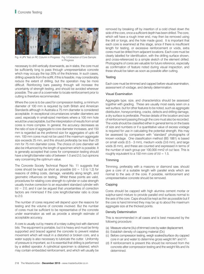
Since the transverse reinforcement lying in the member in the path of the pulse influences the UPV, suitable correction have to be effected for the apparent velocity. Fig. 4 shows a ultrasonic pulse velocity test being conducted on a RC column.
also been developed to measure and evaluate special properties of concrete which are not normally covered under standard practice. A few important tests are described below:
Core Sampling and Core Testing
Core tests serve as a good support test for any field investigation. Special electric or gasoline-driven core drilling machines have been developed to cut cores from the structural members. Cores of 25 mm to 300 mm diameter can be cut including reinforcements, if any, by using these machines. The cores can be tested for compressive strength, chemical analysis, petrographic examination and evaluation of physical parameters. The strength testing of cores provide almost a direct evidence on the quality of concrete as it exists on the structure. It is however necessary to exercise caution in interpreting strength test results of cores as a number of factors, such as diameter of the core, slenderness ratio (l/d), core location, presence of reinforcement and curing condition influence the final results and the relation with cube strength.
Core Testing
The examination and compression testing of cores cut from hardened concrete is a well-established method, enabling visual inspection of the interior regions of a member to be coupled with strength estimation. Other physical properties which can be measured include density, water absorption, indirect elastic strength and other characteristics. Cores are frequently used for chemical analysis following strength testing. In most countries, standards are available, which recommend procedures for cutting, testing and interpretation of results. Taking into account the slenderness ratio and presence of reinforcements, ASTM C 42, ASTM C 192, BS 1881, Concrete Society Technical Report No. 11 and BIS 516:59 give the detailed procedure for core sampling and testing. It is to be noted that Indian Code does not give any formula for evaluating the compressive strength of cores containing reinforcement in its body. Fig. 5 shows a core drilling operation in progress.
General Procedure for Core Cutting and Testing
Core Location and Size
Core location will be governed primarily by the basic purpose of testing, bearing in mind the likely strength distribution within the member and the expected stress distributions. Where the serviceability assessment is the principal aim, cores for test should be normally taken at points where likely minimum strength and maximum stress coincide, for example, from the top surface at near mid-span for simple beams and slabs or from any face near the top of lifts - for columns or walls. If the member is slender, core cutting may impair the future performance and cores should be taken at the nearest non-critical location. Aesthetic considerations concerning the appearance after coring may also sometimes influence the choice of locations. In such cases, areas of suspect concrete may have to be located by using other methods.
If specification compliance determination is the principal aim, the cores should be located to avoid unrepresentative concrete, and for columns, walls or deep beams, cores will normally be taken horizontally at least 300 mm below the top of the lift. If it is
Sl No. Pulse Velocity (Km/sec) Concrete Quality Grading
1 Above 4.5 Excellent
2 3.5 to 4.5 Good
3 3.0 to 3.5 Medium
4 Below 3.0 Doubtful
Note - In case of “doubtful” quality, it may be necessary to carry out further tests.
Reliability and Limitations
The ultrasonic pulse velocity technique has been found to be a valuable and reliable method of examining the interior of a body of concrete in a truly non-destructive manner. The equipment (for example, PUNDIT, V-meter) is robust, reasonably cheap, easy to operate, and reliable even under site conditions. The operators must be well trained and should be aware of the factors affecting the readings. It is equally important that results are properly evaluated and interpreted by experienced engineers, who are familiar with the technique. The least reliable application of this technique is for strength estimation of concrete. The factors influencing calibrations are so many, that even under ideal conditions with specific calibration, it is unlikely that 95% confidence limits of better than + 20% can be achieved for an absolute strength prediction for inplace concrete. However, a qualitative assessment is easily possible on a structure with UPV scanning at a large number of locations. ASTM C597 gives the standard test method for pulse velocity through concrete.
Additional Tests and Recent Developments
In an attempt to minimise the vagaries and controversies in the evaluation of strength of in-situ concrete, developments/improvements continue to take place either in the formulation of new testing techniques or in the improvements of existing techniques. The methods of interpreting the test results of various techniques also get modified as more and more data become available from different sources. In addition, techniques have
Fig. 2 Various methods of UPV MeasurementFig. 3 Crack width Measurement using UPV Test
Concrete Testing
Fig. 1 Rebound Hammer Test
218 The Masterbuilder - December 2013 • www.masterbuilder.co.in
necessary to drill vertically downwards, as in slabs, the core must be sufficiently long to pass through unrepresentative concrete which may occupy the top 20% of the thickness. In such cases, drilling upwards from the soffit, if this is feasible, may considerably reduce the extent of drilling, but the operation may be more difficult. Reinforcing bars passing through will increase the uncertainty of strength testing, and should be avoided wherever possible. The use of a covermeter to locate reinforcement prior to cutting is therefore recommended.
Where the core is to be used for compression testing, a minimum diameter of 100 mm is required by both British and American Standards although in Australia a 75 mm diameter is considered acceptable. In exceptional circumstances smaller diameters are used, especially in small-sized members where a 100 mm hole would be unacceptable, but the interpretation of results from small cores is more complex. In general, the accuracy decreases as the ratio of size of aggregate to core diameter increases, and 150 mm is regarded as the preferred size for aggregates of upto 40 mm. 100 mm cores must not be used if the maximum aggregate size exceeds 25 mm, and this should preferably be less than 20 mm for 75 mm diameter cores. The choice of core diameter will also be influenced by the length of specimen which is possible. It is generally accepted that cores for compression testing should have a length/diameter ratio of between 1.0 and 2.0, but opinions vary concerning the optimum value.
The Concrete Society Technical Report No. 11 suggests that cores should be kept as short as possible (l/d = 1.0 to 1.2) for reasons of drilling costs, damage, variability along length, and geometric influences on testing. Whilst these points are valid, procedures for relating core strength to cylinder or cube strength usually involve correction to an equivalent standard cylinder with l/d = 2.0, and it can be argued that uncertainities of correction factors are minimized if the core length/diameter ratio is close to 2.0.
The number of cores required will depend upon the reasons for testing and the volume of concrete involved. But the number of cores must be sufficient to be representative of the concrete under examination as well as provide a strength estimate of acceptable accuracy.
A core is usually cut by means of a rotary cutting tool with diamond bits. The equipment is portable, but it is heavy and must be firmly supported and braced against the concrete to prevent relative movement which will result in a distorted or broken core, and a water supply is also necessary to lubricate the cutter. Uniformity of pressure is important, so it is essential that drilling is performed by a skilled operator. A cylindrical specimen is obtained, which may contain embedded reinforcement, and which will usually be
removed by breaking off by insertion of a cold chisel down the side of the core, once a sufficient depth has been drilled. The core, which will have a rough inner end, may then be removed using the drill or tongs, and the hole made good. It is important that each core is examined at this stage, since if there is insufficient length for testing, or excessive reinforcement or voids, extra cores must be drilled from adjacent locations. Each core must be clearly labelled for identification, with the drilling surface shown, and cross-referenced to a simple sketch of the element drilled. Photographs of cores are valuable for future reference, especially as confirmation of feature noted during visual inspection, and these should be taken as soon as possible after cutting.
Testing
Each core must be trimmed and capped before visual examination, assessment of voidage, and density determination.
Visual Examination
Aggregate type, size, and characteristics should be assessed together with grading. These are usually most easily seen on a wet surface, but for other features to be noted, such as aggregate distribution, honeycombing, cracks, defects and drilling damage, a dry surface is preferable. Precise details of the location and size of reinforcement passing through the core must also be recorded. The voids should be classified either in general terms on the basis of size and numbers or if a quantitative value of excess voidage is required for use in calculating the potential strength, this may be assessed by comparison with “standard” photographs of known voidage. One classification method (BS 1881) is based on small voids (0.5 - 3 mm), medium voids (3.6 mm), and large voids (6 mm), and these are counted and expressed in terms of the number of each group per 100,000 mm2 of cut face. This is roughly equivalent to a 150 mm core of l/d = 1.5.
Trimming
Trimming, preferably with a masonry or diamond saw, should give a core of a suitable length with parallel ends which are normal to the axis of the core. If possible, reinforcement and unrepresentative concrete should be removed.
Capping
Cores should be capped with high alumina cement mortar or sulphur-sand mixture to provide parallel end surfaces normal to the axis of the core. Caps should be kept as thin as possible but if the core is hand trimmed they may be up to about the maximum aggregate size at the thickest points.
Density Determination
This is recommended in all cases and is best measured by the following procedure:
(a) Measure volume (Vu) of trimmed core by water displacement.(b) Establish density of capping material (Dc)(c) Before compression testing, weigh soaked/surface dry capped
core in air and water to determine gross weight W1 and V1.(d) If reinforcement is present this should be removed from the
concrete after compression testing and the weight Ws and Vs determined.
Fig. 4 UPV Test on RC Column in Progress Fig. 5 Extraction of Core Sample in Progress
Concrete Testing

www.masterbuilder.co.in • The Masterbuilder - December 2013 219
Concrete Testing
(e) Calculate saturated density of concrete in the uncapped core
from
If no steel is present, Ws and Vs are both zero.The value thus obtained may be used, if required, to assess the excess voidage of the concrete using the relationship
Estimated excess voidage = Where Dp = the potential density based on available values for 28 day old cubes of the same mix.
Compression Testing
Compression testing will be carried out at a rate of 15 N / mm2 /min in a suitable testing machine and the mode of failure noted. If there is cracking of the caps, or separation of cap and core, the result should be considered as being of doubtful accuracy. Ideally, cracking should be similar all round the circumference of the core, but a diagonal shear crack is considered satisfactory, except in short cores or where reinforcement or honeycombing is present.
Other Tests on Cores
Whilst compression testing as described above is by far the most common method of testing cores for strength, recent research has indicated the potential of two other methods which are outlined below. Both of these measure the tensile strength, although neither method is yet fully established. Tests for other properties of the concrete, such as permeability or air content may also be performed on suitably prepared specimens obtained from cores.
The point load test, which is an accepted method for rock strength classification may usefully be applied to concrete cores. A compressive load is applied across the diameter by means of a manually operated hydraulic jack with the specimen held between spherically truncated conical platens with a point of 5 mm radius. It has been found that the point load strength index is indirectly related to the concrete compressive strength, although core size and aggregate type affect the relationship. For a given aggregate and core size, the index varies linearly with cube strength for strengths greater than 20 N/mm2. The testing variability is comparable to that expected for conventional core testing. The advantages of this approach are that trimming and capping are not required and that the testing forces are lower, thus permitting the use of small portable equipment on site at a reduced unit cost.
The point load test is essentially a tensile test, but data relating results to other forms of tensile testing are unfortunately not available. The greatest potential for future development of this method may perhaps lie as a means of estimating in-situ tensile strength.
Interpretation of Results
Factors influencing measured Core Compressive Strength
These may be divided into two basic categories according to whether they are related to concrete characteristics or testing variables.
Concrete Characteristics
The moisture condition of the core will influence the measured strength - a saturated specimen has a value 10-15% lower than a comparable dry specimen. It is thus very important that the relative moisture conditions of core and in-situ concrete are taken into account in determining actual in-situ concrete strengths. If the core is tested whilst saturated, however, comparison with standard control specimens which are also tested saturated will be straight forward.
The curing regime, and hence strength development, of a core and of the parent concrete will be different from the time of cutting. This effect is very difficult to assess and in mature concrete may be ignored, but for concrete of less than 28 days, this effect should be considered.
Voids in the core will reduce the measured strength, and this effect can be allowed for by measurement of the excess voidage when comparing core results with standard control specimens from the point of view of material specification compliance.
Testing Variables
These are numerous, and in many cases will have a significant influence upon measured strength. The most significant factors are outlined below:
Length/Diameter Ratio of Core
As the ratio increases, the measured strength will decrease due to the effect of specimen shape on stress distributions whilst under test. Since the standard cylinder used in many parts of the world has a length/diameter ratio of 2.0, this is normally regarded as the datum for computation of results, and the relationship between this and a standard cube is established.
Diameter of Core
The diameter of core may influence the measured strength and variability. Measured concrete strength will generally decrease as the specimen size increases; for size above 100 mm this effect will be small, but for smaller sizes this effect may become significant. As the diameter decreases, the ratio of cut surface area to volume increases, and hence the possibility of strength reduction due to cutting damage will increase. It is generally accepted that a minimum diameter/maximum aggregate ratio of 3 is required to make test variability acceptance, although a higher value should preferably be used.
Direction of Drilling
As a result of layering effects, the measured strength of a specimen drilled vertically relative to the direction of casting is likely to be greater than that for a horizontally drilled specimen from the same concrete. Published data on this effect is variable, but an average difference of 8% is suggested. Whilst standard cylinders are tested vertically, cubes will normally be tested at right angles to the plane of casting and hence can be related directly to horizontally drilled cores.
Method of Capping
Provided that the materials recommended have been used, their

220 The Masterbuilder - December 2013 • www.masterbuilder.co.in
strength is greater than that of the core, and the caps are sound, flat, perpendicular to the axis of the core and not excessively thick, the influence of capping will be of no practical significance.
Reinforcement
Published research results indicate that the reduction in measured strength due to reinforcement may be less than 10%. Rein-forcement must therefore be avoided whenever possible, but in cases where it is present the measured core strength must be corrected and treated with caution.
Estimation of Cube Strength
Estimation of an equivalent cube strength corresponding to a particular core result must initially account for two main factors. These are:
(a) the effect of the length/diameter ratio, which requires a correction factor to be applied to convert the core strength to an equivalent standard cylinder strength, and
(b) conversion to an equivalent cube strength using the generally accepted average relationship: Cylinder strength = 0.8 x cube strength.
The result should be quoted to the nearest 0.5 N/mm2. This approach takes no account of features such as orientation of drilling relative to casting. The results obtained are thus of doubtful value since they are unlikely to represent a realistic estimate of in-situ cube strength. An 8% difference between vertical and horizontal drilled cores is also incorporated with the resulting expressions emerging:
Horizontally Drilled Cores
Estimated cube strength =
Vertically Drilled Core
Estimated cube strength =
where f is the measured strength of a core with length/diameter =
It is interesting to note that, using these expressions, the strength of a horizontally drilled core of length/diameter ( ) = 1 will be the same as the equivalent cube strength. The cube strengths evaluated in this way will be estimates of the actual in-situ strength of the concrete in a wet condition.
Reliability, Limitations, and Applications
The likely coefficient of variation due to testing effects is about 6% for carefully cut and tested cores, which can be compared with a corresponding value of 3% for cubes. This difference is largely caused by the effects of cutting, especially since cut aggregate particles are only partially embedded in the core and may not make a full contribution during testing.
The principal limitations of core testing are those of cost, inconvenience and damage, and the localized nature of the results. It is strongly recommended that core testing is used in conjunction with some other form of testing which is less tedious and destructive. The aim of this is to provide data on relative strengths within the body of the concrete under test. The size
of core needed for reliable strength testing can pose a serious practical problem; “small” cores may be worthy of consideration with slender members. It may also be appropriate to consider using a larger number of “small” diameter cores to obtain an improved spread of test locations where large volumes of concrete are involved. The cutting effort for three 50 mm cores may be as low as one-third of that for one 150 mm specimen, and a comparable overall strength accuracy may be expected, provided that maximum aggregate size is less than 17 mm. Where cores are used for other purposes, it will often be possible to use a “small” diameter with considerable savings of cost, inconvenience and damage.
Apart from physical testing, cores often provide the simplest method of obtaining a sample of the in-situ concrete for a variety of purposes, but care must be taken that the effects of drilling, including heat generated by friction, or the presence of water, do not distort the subsequent results. A sample taken from the centre of a core may conveniently overcome this problem. Chemical analysis can often be performed on the remains of a crushed core, or specimens may be taken specifically for that purpose. Visual inspection of the interior of the concrete may be extremely valuable both for the assessment of compaction and workmanship, and for obtaining basic data about concrete for which no records are available. In cases where structural assessments of old structures are required, cores may also prove valuable in confirming covermeter results concerning the location and size of reinforcement.
Tests for Corrosion Detection and Monitoring
Corrosion of reinforcing steel in concrete structures is a menacing problem quite often threatening the life of a structure. Considerable amount of research work has been carried out to understand the factors influencing corrosion and to evolve technique for corrosion detection and repair of corrosion damaged structures.
Corrosion of steel in reinforced concrete is basically an electro-chemical phenomenon. Ingress of salts (Chlorides and sulphates) into concrete de-passivates the steel and sets in galvanic cells with moist concrete acting as an electrolyte. A potential difference occurs resulting in current flow. Further ingress of moisture and oxygen accelerates the current flow and sets in more rapid corrosion.
The factors which influence corrosion are:
• Quality of concrete • Depth of cover • pH value of concrete• Salt content (Chloride and sulphate) in concrete • Level of moisture • Permeability characteristics of concrete • Environmental conditions
Since a number of factors influence the corrosion process, it is difficult to detect or monitor corrosion in a structure with one single equipment or technique. It is necessary to study both the concrete characteristics and electrochemical parameters and only a combination of a number of tests can lead to a correct and reliable assessment of the condition of a structure. Details of such combination of tests are described below:
Tests for Quality of Concrete
The previous sections have to a large extent, dealt with the
Concrete Testing

222 The Masterbuilder - December 2013 • www.masterbuilder.co.in
various tests on quality of concrete. Tests such as ultrasonic pulse velocity, hammer test, and concrete-coring help to assess the quality of concrete as it exists. These tests on a corrosion-prone structure can be carried out to detect defects, surface laminations, presence of voids and cracks, and denseness of concrete. The results of such tests can be used to identify the weak zones where the possibility of corrosion attack is more. Such zones are marked for further tests to monitor the electrochemical parameters. The core samples taken from the structure can be used for chemical analysis and examining for porosity, permeability, moisture content, and mix proportions.
Test for Concrete Cover
The cover thickness in concrete members plays an important role in the corrosion process. If the cover thickness is less, the ingress of salt and moisture is quicker which initiates the corrosion at an early age.
A commercially available ‘cover meter’ serves as an effective instrument for measurement of cover thickness and location of reinforcing steel. This instrument, also known as ‘Profometer’ works on the principles based on the damping of a parallel-resonant circuit. An alternating current with a given frequency flows through the probe coil, thus creating an alternating magnetic field. If the diameter of the rod is known, the cover thickness can be read directly from the instrument which is provided with a scale based on laboratory calibration tests.
Potential Measurements
The potential measurements on reinforcement ascertain probability of corrosion. The test procedure consists of measuring potential variation between the concrete surface and the reinforcement using reference electrodes and high-impedance voltmeter. A qualitative assessment can be based on following guidelines:
- Steel not corroding has a potential more positive than -250 mV- Steel corroding has a potential more negative than -350 mV.
Resistivity of Concrete
The current that flows in the corrosion process is largely controlled by the resistivity of the concrete. This, in turn, controls the metal loss in a corrosion cell for a measured potential. The resistance of the concrete can be measured by a 4-probe technique using an alternating current and resistance-meter. An assessment can be made on the following guidelines:
Chloride Content
Chloride content in hardened concrete can be found from samples by a chemical analysis in the laboratory. It can also be determined at site by a test kit called Rapid chloride test (RCT) kit.
Water Permeability Test
Permeability characteristic of concrete plays an important role in the corrosion process of steel reinforcement. It is important to know the permeability characteristic of critical portions in a reinforced concrete structure. A test kit, known as Water Permeability test kit is now available commercially. The test consists of clamping the unit on the concrete surface and filling the housing with water.
Water pressure is established by turning an adjustable nut. The selected pressure is maintained by a micrometer. Readings on the micrometer gauge are directly related to the permeability.
Concrete Testing
Resistivity (Ohm-cm) Rate of corrosion
Greater than 20,00010,000 - 20,0005,000 - 10,000Less than 5,000
NegligibleLowHigh
Very high
Concluding Remarks
The tests outlined here are not exhaustive. There are more testing techniques of different principles and application to evaluate the properties of concrete. The material, concrete is so complicated in nature that the efficiency and quality of the material cannot be established just by one single test. Field tests are increasingly becoming important due to the uncertainties in the durability of concrete in the actual structures. Most of the tests which are used for estimating the parameters of concrete provide an excellent means of establishing and evaluating uniformity of concrete and, their use in the aspect of quality assurance programme in concrete structures is promising. The in-situ, nondestructive tests should be used only when comprehensive laboratory correlations are established on the parameters to be predicted. Interpretation of results should be done with abundant caution and a great deal of training and experience is required before one can test a structure.
References
- American Society of Testing Materials (ASTM), “Significance of Tests & Properties of Concrete and Concrete Making Materials”, Special Technical Publication 169 B, Dec. 1978
- American Concrete Institute, “In Situ/Non-destructive Testing of Concrete”, V.M. Malhotra (Editor), SP-82, 1984
- Annual Book of ASTM Standards, Part 14, “Concrete and Mineral Aggregates (Including Manual of Concrete Testing)’
- Joseph J. Waddel, “Practical Quality Control for Concrete”, McGrew-Hill Book Company, Inc.
- Instruction Manual, “PUNDIT” Ultrasonic Tester- BS 4408: Part 5:1974, “Recommendations for Non-destructive Methods of test
for Concrete”, British Standards Institution- ACI Manual of Concrete Practice 1984 Part 1, Materials and General Properties
of Concrete- Malhotra, V.M., “Testing Hardened Concrete: Non-destructive Methods”,
American Concrete Institute, Monograph No.9, Detroit 1966- Jones, R., “Non-destructive Testing of Concrete”, London, Cambridge
University Press, 1962- Whitehurst, E.A., “Evaluation of Concrete Properties from Sonic Tests”,
American Concrete Institute, Monograph No.2, Detroit, 1966- “Testing of Concrete”, BS 1881, Part I to Part 6, British Standards Institution,
London, 1983- Guide to assessment of concrete strength in existing structures’, BS 6089,
British Standards Institution, London, 1981- Malhotra, V.M. and Carette, G., “Comparison of pull-out strength of concrete
with compressive strength of cylinders and cores, pulse velocity and rebound hammer”, CANMET Report 77-8, Mineral Sciences Laboratories, Dept. of Energy, Mines, and Resources, Ottawa, `1975
- Ramakrishnan, V., ‘Past and future’ of concrete quality Processing, ASCE, V. 102, June 1976
- Browne, R.D., Domone, P. and Ceoghegam, M.P., “Inspection and Monitoring concrete structures for steel corrosion”, Offshore Technology Conference, Proceedings, Vol.1, Dallas, Texas, 1977
- RILEM, “International Symposium Testing in-situ of concrete structures”, Proceedings of RILEM Symposium held in Budapest, Sept. 1977
- Bungey, J.H., “The Testing of Concrete in Structures”, Surry University Press, London, 1982.