quality control for automatic inspection of …doras.dcu.ie/18327/1/osama_mohammed_basmage.pdf ·...
TRANSCRIPT

QUALITY CONTROL FOR
AUTOMATIC INSPECTION OF THREADED COMPONENTS
BYOSAMA MOHAMMED BASMAGE
This thesis is submitted as the fulfilment of therequirement for the award
of degree ofMASTER OP ENGINEERING(M.Eng.)
By Research from
DUBLIN CITY UNIVERSITY (DCU)
Sponsoring Establishment:
SCIENTIFIC STUDIES AND RESEARCH CENTRE (SSRC)
DAMASCUS, SYRIA ARAB REPUBLIC
AUGUST 1991

772¿ I J Ü I W
idtá)w iS'SK$woJi£ow 3ya , H V 1TV
Jjo zyofrc itfbjci

ACKNOWLEDGMENT
(
I would like to express my sincerest gratitude to the project supervisor Dr. M.EL.BARADIE, who originally conceived the project and who guided me in a very professional manner throughout the course of the research.In particular I would like to express my sincere appreciation to professor M.S. J.HASHMX, head of school of mechanical & manufacturing engineering (DCU), for his valuable advice encouragement, guidance and also supervision during the course of this research.I would like to express my sincere thank to Dr. A.W.CHAHID, the general director of the SSRC. and Dr. GH.MOUSSA, home supervisor.I acknowledge the assistance given by the government of
Syrian Arab Republic,for providing financial support toward this research via Scientific Studies And Research centre.Also I wish to thank I.HOOPER and J.TRACEY from the workshop of the school for their support at various stages of this work.

Heartfelt thanks are due to my lovely wife (N.ACHOUR), and my children (MOHAMMED, NOUR) . Not only did they provide loving support, but my wife also provided hours of typing as the thesis was prepared.Finally, many thanks to my father, mother, brother, sister ancl mother in law for their blessing and prayers.

DECLARATION
I declare that all the work described in this thesis is entirely the work of the author, performed whilst undertaking the research project in the period January 1990 to August 1991. This thesis has not been submitted as an exercise for degree at any other Institute or University.
Date
26th of August, 1991 DUBLIN OSAMA.N.BASMAGB.

Internal ExaminersDr. M . A .EL Baradie
1 /
H ù iì/clJ ì l j ì
External Examiners Dr J .Monaghan
H
Head of Schoo1 I Professor M.S.J.Hashmi

NOTATION
c
d : Nominal diameter of thread (mm) .S : r.p.m of work.N : r.p.m of cutter,n : Number of teeth in cutter.f : reed per revolution.
*
M, : Measured value.Tw : True value.M, : Maximum scale value.Sen : Sensitivity.C.O.S: Change of output signal.C.I.S: Change of input signal, y : Function,x : Variable.C, m : Constants.m1 : Motor number one.m2 : Motor number two.A : The lowest limit of accuracy.K : Relative linearity error.1C» : True value of quantity.Kb : Observed value.X : Statistical mean.0- : Standard deviation.Ta : Developed torque

I. : Current.wB : Shaft velocity.V : Linear velocity,w : Angular velocity.4 : Flux.Tb : The torque developed on the motor shaft,k* : Developed torque.T : Torque produced by motor.E : Voltage accrose the motor.J : Inertia.CL : Centre line.LL : lower limit.UL : Upper limit.BS : British Standard.SQC : Statistical quality control.LVDT : Linear Variable Differential Transformer.

ABSTRACT
f
Manual inspection and testing of threaded components, specially in high volume manufacturing processes are time consuming and costly.
There are three different types of error which may occur within the tolerance zone specified by the metric thread ISO system, which are as follows:(i) Error of the flank angle.(ii) Error of pitch over the length of fitting.(iii) Error of effective diameter.
Additionally, material build-up which blocks the threaded zone may also render the component to be rejected. These error may occur due to the manufacturing process itself, either by cutting or rolling, such as tool and die wear, materials defects , etc.
This thesis describe the design and development of an automatic inspection system for threaded components.
The system consists of a mechanical sensor, which is interfaced to a PC and the operational tracing cycle of the system is controlled to carry out the following operations.
(1)- Belix path inspection.(2)- thread form inspection.
The results of the helix path and the thread form tracing are presented for the ISO metric thread: (M6), <M8), and (M16), together with the operational cycle.

CONTENTS LIST
CONTENTS PAGE
• Title of the thesis.
- Dldlcatlon.
• Acknowledgment.
- Declaration.
• Notation.
- Abstract.
- Contents list.
CHAPTER ONE.
1- Introduction................................. 1
CHAPTER TWO.
2- Literature Survey........................... 5
2-1 Measurement and Standard................... 5
2-2 Basic Metrological concepts--------- ....... 6
2-3 Classification of measuring methods and means

2-4 Automated Inspection principles and methods 8
2-5 Sensor technologies for automated Inspection... 10
2-6 Sensor In the production and quality control... 12
2-7 Literature survey for the screw thread Inspection 12
CHAPTER THREE
3 - Screw & screw measurement............... 25
3-1 Definition for use In mechanical engineering 25
3-1*1 General............................... 25
3-1-2 Geometry of screw thread.............. 28
3-1-3 Pitch of screw threads................. 34
3-1-4 Diameter of screw threads.............. 38
3-1-5 Assembly of screw threads............... 39
3-2 Type of screw threads_____ ......— ■ 39
3-3 Methods of manufacturing threads............... 42
3-3-1 Cutting screw threads on a lathe......... 45
3-3-2 Taps and dies............................ 46
3-3-3 Thread chasing........................... 47
3-3-4 Tapping machine......................... 48
3-3-5 Thread milling........................... 49
3-3-6 Thread rolling........................... 50
3*3-7 Thread grinding......................... 55
3-4 Error of screw threads ........ 56
3-4-1 Effective diameter..................... 56
3-4-2 Pitch................................. 58
3-4-3 Error In pitch In relation to effective.. 61
diameter.
3-4-4 Error In angle In relation to effective.... diameter. $2
3-4-5 Radii at crest and root................... 65
3-5 Control of accuracy of pitch.................. 66
3-6 Nomenclature and specification------------- 67
3-6*1 ISO Metric screw threads.................. 69
3-6-2 Basic dimension......................... 69
3-6-3 Tolerance zone and class of fit 73
3-6-4 Application of f it ................ 74
3-6-5 Designation.............................. 75
3-7 Inspection of screw thread................... 79
3-7-1 Inspection by gauging......................79
3-7-2 Inspection by measurement................. 80
CHAPTER FOUR/
4- Development of the measuring rig..................81
4-1 Definitions.................................... 81
4-2 Principles of design............................ 85
4-2-1 Kinematics principles........................85
4-2-2 Basic characteristic of measuring devices 87
4-2-3 Intelligent Instrumentation..................89
4-3 Design and development of an automatic inspection system
4-3-1 Mechanical design......................... 91
4-3-1-1 Lever mechanism......................... .93
4-3-1-2 Clamping and rotating mechanism 95
4-3-2-3 Sliding mechanism........................102

4-3-2 Electronic design.......................... 104
4-3-2-1 Motors.................................. 107
4-3-2-2 Linear variable differential design 110
4-4 Computer Interfacing and signal processing 114
4-4-1 Computer Interfacing.......................115
4-4-2 Signal conversion: Digital to Analog....... 116
4-4-3 Signal conversion: Analog to digital....... 117
4-4-4 Interfacing the motors and the LVDT ........117
4-4-4-1 Signal conversion: D/A (DAC-02) CARD 118
4-4-4-2 Signal conversion: A/D (DASH8) CARD— 120
4-4-5 Specification of transducer amplifler......l23
type S7M.
4-5 Calibration................................... 125
4-6 Software design............................... 126
CHAPTER FIVE
5 - Experimental Results............................129
5-1 The measuring principles........................129
5-2 The operational cycles......................... 132
5-2-1 Clamping the object.......................... 132
5-2-2 Stylus contact------------- ......--------132
5-2-3 Generating the linear and the angular motlon...132
5-2-4 Generating the linear motion..................135
5-2-5 Releasing the object and displaying the,. 135
5-3 Experimental procedure........................137
5-3-1 Calibrations................................. 137
5-3-2 Recommendations __________139

5-4 Inspected objects...............................139
5-5 Linear and angular velocities...................141
5-6 Experimental results............................141
5-6-1 Experimental results of the bolt size M6 142
5-6-1-1 Form Inspection............................142
5-6-1-2 Helix Inspection............................142
results.
5-6-2 Experimental results of the bolt size M8 142
5-6-2-1 Form Inspection.............................148
5-6-2-2 Helix Inspection............................148
5-6-3 Experimental results of the bolt size M16..... 148
5-6-3-1 Form Inspection.............................158
5-6-3-2 Helix path Inspection.......................158
5-6-3-3 Artificial defect on the crest.of M16......168
5.6-3-4 Artificial defect on the helix path of M16...168
CHAPTER SIX
6 - Results and Discussion......................... 172
6-1 Discussion of the experimental results.......... 172
6-2 The form Inspection results....................173
6-2-1 The result of the bolt size M6................ 173
6-2-2 The result of the bolt size M8................181
6-2-3 The results of the bolt size M16...............186
6-3 The discussion of the helix path results 198
6-3-1 The results of the bolt size M6_______ 198
6-3-2 The results of the bolt size M8 ..... 201

6-3-3 The results of the bolt size M16........
6-3-4 Artificial defects........................... 216
7- CHAPTER SEVEN
7- Conclusion................................... 221
7-1 Conclusion................................... .221
7-2 Recommendation for further work..........
References.
Appendlxs.

CHAPTER ONE
1 - INTRODUCTION
In the recent years there has been a significant growth in the use of tactile probes as on-line inspection system for machine tool applications.These probes are mounted in holders, inserted into the
machine tool spindle, stored in the tool drum, and handled by the automatic tool changer in the same way that cutting tool are exchanged. When mounted in the spindle, the machine tool is controlled very much like a CMM.
Sensors in the probe determine when contact has been established with the part surface. Signals from the sensor are transmitted by any of several different means to a controller, which performs the required data processing to interpret and utilize the signal.Touch sensitive probes are sometimes referred to as in- process inspection devices. These probes are sometimes used between machining steps in the same setup.Some of the other calculation features of machine mounted inspection probes are similar to the capability of
j
1

computer-assisted CMMs.The features include determining the centre-line of
a cylindrical part or hole, part and determining the coordinates of an inside or outside corner.One of the controversial aspect of machine-mounted inspection probes is the fact that the same machine tool which makes the part is also performing the inspection .
In practice, however, the use of these devices has proved to be effective in improving quality and saving time in expensive off-line inspection operations . [8]
This thesis is mainly concerned with the application of quality control to threaded components.An automatic measuring system have been developed in order to inspect the external screw threads.
In chapter two we define the measurement and standards, describe the different basic metrological concepts and the classification of the measuring methods and means, provide the automatic inspection principle and methods, in addition to the reasons of using it.
And because of the strong relationship between the automatic inspection and the sensor technologies, an explanation of sensor technologies as applied to automated inspection is given.Also in this chapter the literature survey for screw threads, which represent the different techniques, methods, attempts to develop the methods, of inspecting the screw thread.
2

While chapter three gives the definitions of the screw thread for the use in mechanical engineering applications then, there are a description of the different types of the screw and the various methods of manufacturing them.
Also the different errors of the screw thread, of these effective diameter, pitch, error in pitch in relation to effective diameter, error in angle in relation to effective diameter and error at crest and root ofjthe thread.
In addition the control of accuracy of the ISO metric screw thread which includes the basic dimension, tolerance zone and class of fit, application of the class of fit, and the designation of the screw thread are presented. The last section of this chapter explains the two general methods of inspecting screw threads (gauging, measuring).
\
In chapter four special definition forinstrumentation then describes the various principles of the design which include, the kinematic basiccharacteristic of measuring devices and intelligent instrumentation.Also a full explanation is given about the design anddevelopment of our automatic measuring system whichconsists of two main elements (mechanical andelectronic).
These are interfaced to a personal computer forcontrolling and processing the different input/output
3

signals. Therefore two signals conversion are described with their calibration and that of the linear variable differential transformer (L.V.D.T) .At the end of this chapter there is an explanation of the software development.
The measuring principle of the system is illustrated at the beginning of chapter five, also the operational cycles explain the consequence of the measuring process due to the profile form and helix path inspections.
While the experimental procedure describes the importance of calibration and its effects on the results. The three ISO metric screw thread M6, M8 and M16 are used. The different results are presented at this chapter, beside that, the different linear and angular velocities used for inspecting these bolts are illustrated.
Chapter six, is mainly concerned with discussing, comparing and analyzing the different results which
were obtained due to the various experiments.Finally, chapter seven represents the conclusion of this
work, and the recommendation for further work.
4

CHAPTER TWO
2 - LITERATURE SURVEY
2-1 Measurement and standards.
Measurement is the most fundamental method of science. It is the process of empirical, objective, assignment of numbers to properties or events of the real world in such a way as to describe them [1] . All measurements are actually relative in sense that they are comparisons with some standard units of measurement [2]. The progress of measurement has played a large part in man's scientific advancement.Early attempts at standardization of length measurements were based on the human body. The width of finger was termed a digit, and the cubit was the length of the forearm from the end of the elbow to the tip of the longest finger. These measurements were in use at the time of the construction of the Khufu pyramid [3], [4],[5], [6], [7].Accurate measurements are important to physics, business and finance, agriculture, medicine and health and to many everyday activities such as and travel, sports and
5

recreation cooking and baking, and communications and entertainment-[2].Engineering dimensional measurement involves the euclidean concepts of the straight line and plane. Linear measurements are ratios expressed in terms of some arbitrary length standard, e.g. the Imperial Standard Yard or the International Prototype Metre.Other forms of length standards are possible, but present primary length standards are defined in terms of the wavelength of monochromatic light. The establishment of the of an absolute length standard belongs to the realm of physics rather than engineering ,[8], [9].
2-2 Basic Metrological Concepts.
Metrology is mainly concerned with:<U- Establishing the units of measurement,
reproducing these units in the form of standards, and ensuring the uniformity of measurement.
(2)- Development methods^of measurement.(3)- Analyzing the accuracy of methods of measurement
researching into the cause of measuring errors, and eliminating these.
The principle of measurement is the physical phenomenon utilized in the measurement, while the method of measurement is the way the measuring principles and measuring means are used [3].
6

2-3 Classification of Measuring Methods And Means.
A measuring instrument is any device that may be used to obtain a dimensional or angular measurement [10] . Measurements can be generally classified as direct and indirect ones. Direct measurement are mostly used in engineering because they are simpler to perform and give immediate results.The methods of measurement are also classed as the composite ( or cumulative ) method and the element method. The composite method is the most reliable method for ensuring interchangeability and is usually effected through the use of composite " GO " gauges.The composite method is mainly used for checking product parts [3], mass production for instance [2]. The element method for checking tools and for detecting the cause of reject in product.Contact measurement involves the direct engagement of the instrument measuring faces with the surface of the part being measured.Non-Contact measurement features the absence of any physical contact of the instrument with measured part. The means of measurement used in the metalworking industries can be divided into three main groups, namely:
(1)- STANDARDS.
(2)- FIXED GAUGES.(3)- UNIVERSAL MEASURING TOOLS and INSTRUMENTS.
Here are a number of the common measuring instruments listed according to [10], use:
7

(a) - Linear measurement.1- Measuring machine
a- Mechanical. b- Optical.
(b) - Angular measurement.(c) - Plane surface measurement.<d) - All-Purpose special measurement.
1. Pneumatic.2. Electric.3. Electronic.4. Laser.
2-4 Automated Inspection Principles and Methods.
Automation is a technology concerned with the application of mechanical/ electronic, and computer based systems to operate and control production.Inspection and testing activities represent one of the five basic functions in manufacturing ( Processing, Assembly, Material handling and Storage, Inspection and Test, Control ) as shown in figure (2-1).When SQC (statistical quality control) inspection and testing are carried out manually, the sample size is often small compared to the size of the population. The sample size may only represent 1% or fewer of the number of parts made in a high-production run. In principle, the only way to achieve 100% good quality is to use 100% inspection.By this approach, theoretically, only good-quality parts
8

Factory operations
Raw materials1. processing.2. Assembly.3. Material handing.
4• Inspection and test•
Receiving
5. Control.
Finished Product
Figure (2-1)Model of the factory showing five
function of manufacturing.

will be allowed to pass through the inspection procedure.100% inspection using manual methods is no guarantee of 100% good quality product. Automation of the inspection process offers an opportunity to overcome the problems associated with 100% manual inspection. Automated inspection is defined as the automation of one or more of the steps involved in the inspection procedure [8] .
2-5 Sensor Technologies For Automated Inspection.
The sensing element is the first element in the measurement system; it is in contact with, and draws energy from, the process or system being measured [11] . The new approaches to the quality control function are based on advanced sensor technology often combined with computer based systems to interpret the sensor signal, in addition, new software tools are being developed to automate the operation of complex sensor system and to statistically analyze the sensor measurement.Modern automated inspection procedures are typically carried out by sensor [8]. Sensors can obtain range data, at high speed are an increasingly important part of development in the field of robotics, automated inspection and assembly [2].A transducer is defined as a device that receive energy from one system and retransmits it, often in a different from, to another system.On the other hand, a sensor is defined as a device that is sensitive to light, temperature, electrical impedance,
or radiation level and transmits a signal to a measuring/ior control device [13].
There are a variety of technologies available for automated inspection [8] . A detailed survey of the types of sensors developed for this purpose is given in [14]. Contact inspection methods involves the use of a mechanical probe or other device that makes contact with the object being inspected.The purpose of the probe is to measure or gauge the object in some way. By its nature, contact methods are usually concerned with some physical dimension of the part.Accordingly, contact inspection methods are used predominantly in the mechanical manufacturing industries (e.g., Machining and other Metal working, Plastic moulding, etc,).
Three methods of automated contact inspection that present the high end of the technology spectrum are:
(1)- Coordinate measuring machines.(2)- Flexible inspection system.(3)- Inspection probes.
Non-contact inspection methods do not involve direct contact with the product, instead, a sensor is located at a certain distance from the object to measure or gage the desired features [8].
11

2-6 Sensor In The Production And Quality Control.
There are two basic types of sensors. One that produces an output proportional to a change in a parameters is described as an analog device; one that produces an on/off type of output is described as a digital device [15] . Measurement in all its form is an essential part in achieving quality [10].Sensors are currently used in a large variety of phases
of production process in order to realize more systematic process control a campaigned by tighter quality control [16] .Considerable progresses have been achieved in sensor technique [17], [18], these techniques have demonstratedproductivity enhancing quality control inspection automation for many type of parts [19], [20], [21].A number of measuring and controlling tasks must be carried out automatically with appropriate sensor [22] . Non-contact distance sensors are divided into three categories depending on their mode of operation; mechanical, electromechanical, and electromagnetic [33].Sensors for inspection or quality control must have the following features: processing speed and flexibility on one hand, and easiness of operation and reasonable price on the other hand [24].
2-7 Literature Survey For The Screw Threads Inspection.
A screw thread is a ridge of uniform section in the
12

form of a helix on the external or internal surface of a cylinder, on in the form of a conical spiral on the external or internal surface of a frustum of a cone. They probably are the most important of all the machine elements [7].
—i
The inspection of screw threads may be by gauging or measuring [25]. Normally they are inspected using limit gauges, but certain threads must be held to much closer tolerances, and this is particulary true of the limit gauges used for screw thread inspection. These threads must be measured, not gauged, so that they are of degree of accuracy to separate successfully the good threads from the bad when used as tools of inspection [26].BS 919: " Screw Gauge Limits And Tolerances " , part 3 " Gauges For ISO Metic Screw Threads ", contains the recommended gauging system for checking threads of nominal diameters 1mm and larger which have been made in accordance with BS 3643 " ISO metric screw threads Measurement of a screw thread can be very complex, there being a number of elements to be measured, some of which are interrelated [25], [9].A screw-thread comparator-a microscope for measuring elements of an external thread appeared in 1925, it was a predecessor of the universal microscope produced in 1926. Optical dividing heads also appeared in 1925. Electrified measuring instruments of different types, such as electric switch gauge heads, indicative, capacitance and photoelectric transducers, etc have been developed since 1930s.
13

The introduction of these devices gave an impetus to the development of automatic gauging, thus automatic gauging machines with electric switch heads have been produced since 1937.The main trends in further development of measuring means are: higher accuracy through better construction and the application of new physical principles; higher inspection productivity through the use of special-purpose, mechanized and automatic gauges: and the introduction of automatic gauging control over machining operations to avoid scrap [3] .In a flexible production system, the duties of quality assurance can not be limited to a GO/NO-GO inspection of the workpiece [27],[28],
Dimensional measurement was and always will be a vital need [10],[29], automated equipment able to perform the functions of guidance, quality assurance, measurement and process control, [29], [30].The rising cost of quality control functions in the
manufacturing sector and the increasing demands for 100% [31], [32], product inspection have stimulated thedevelopment of low cost yet powerful automatic inspection devices to augment the functions of human inspectors [31] .Sensors, together with powerful computers, form a basis for flexible automation in the fields of dimensional measurement techniques and inspection [33].A method for measuring the surface profile [34], using different techniques can be implemented to operate under
14

Several systems have been developed for inspecting screw threads, using different techniques. A device which consisted of the non-contact type optical feeler and the automatic screw lead measuring machine with a laser interferometer, had produced [35] .Batchelor [36], introduces the screw inspection problem in term of pattern recognition. Techniques are discussed for inspection male screw threads an automatic image analysis applied to their profile for measuring:
(a)- Pitch.(b)- Depth of thread.(c)- Flank angle.(d) - Radius of curvature of the crest and roots.
The ideas are all based upon well-known of visual pattern recognition techniques, the Freeman (chain) code of the profile edge is first derived and is then converted to a sequence of vectors from which a polygonal are touching the crests of the thread may be derived. Similarly an arc touching the roots can be obtained. From the crest and root arcs, another polygonal arc approximating the pitch line can be calculated.The intersections of this arc with the profile are quite accurate indicators of the flank centres. The flank angle may then be derived by measuring the edge orientations at these intersection.The distance between alternate intersections is an
computer control [20].
15

estimator of pitch. The separation of the crest and root and arc is a measure of the depth of thread. A simple optical system, resembling a shadow graph may be used to obtain a silhouette of the bolt to be inspected. The bolt can be aligned roughly using a comb-like jig and a twin- strip camera seems to offer the best resolution. Using the longest photodiode array currently available (1728 diodes) and mechanical scanning, a resolution of 2000 x 1728 might be achieved.Batchelor has not yet had the opportunity to incorporate these ideas into an one-line inspection system, also another idea Batchelor has not yet had the chance to investigate is that of rotating the bolt during inspection.The vision system developed by horaud [37], and charras for the screw thread inspection is constituted of figure (2-2), a vidicon camera, amplification, clamp and sampling electronic circuits, grey level and gradient detectors, direct memory access devices and a PDP-11 minicomputer system with its software facilities. The acquisition time of a 200 x 512 high resolution picture ( black and white pixels or white edges on black background ) is only 1/25 seconds.The techniques developed can be used to classify the items into good or detective ones. Batchelor, also, introduces a proposals for the automatic visual inspection of female screw threads, a method relies upon a conical mirror which transforms a helix into a spiral image, the imaging system is mathematically analyzed.
16

Figur« (2-2 )
17

Techniques are used for verifying that a thread exists, checking that the thread has a given pitch, measuring the pitch, and checking for surface defects [38].Another techniques have been developed, [39] to include the measurement of internal threads in the automatic measurement.A programm has been developed for the CNC measuring centre, which permits the automatic testing of internal threads using a special feeler.The measuring cycle for the measurement of threads are limited to measurement taken at the thread start and thread end , this being fully adequate for functional testing.The feeler's starting position in this sequence of thread measurement is defined by the bore centre and the thread surface. It can be fixed by presetting the demanded value or by manual selection .In manual positioning, the thread surface is contacted with the feeler point and the feeler point is then positioned above the bore centre.Deviations from the bore centre are permissible, since the movement a long the coordinate axes will go on until the feeler touches the workpiece, figure (2-3).For measurement, it is essential that the measuring points for determining the pitch diameter should be recorded in the first fully cut thread. This is done by moving from the starting position to the thread start by an amount that depends on the thread countersink and the height of the open thread flank. The first measuring
18

*eeler’a starting position
Figure l*-»>. ttiread tl*nXs
g c a n n i r'<3 °
„ 4 0 0 » M l *
19

point will then be recorded in a self-centring manner.A flank contact test helps to make sure that the sensing ball is in contact with the thread flank and in this test, a movement is made parallel to the thread axis by an amount that is greater than the flank height in the core hole area and, in this position, a second measuring point is recorded in a self-centring manner.The comparison of the two measuring points permits a statement to be made as to which one of the two has been determined as flank contact. After recording a third measuring point, the pitch of the thread will be obtained.The position of the thread and the pitch diameter will be determined with the aid of further measuring points on the periphery of the first thread and through a circle calculation, followed by a correction of the sensing-ball radius.The test of the thread depth is carried out by performing a full-flank test after movement into the given specified depth of the thread.For this purpose, a flank contact test as the thread start will be carried out at first. The average pitch diameter and the axial location of the thread can be computed from the measuring points at the start and end by means of a cylinder calculation.Fully- automated inspection on flexible thread inspection centre : this method of inspection is a multi-pointinductive probing.A wide variety of measured values is recorded and single
20
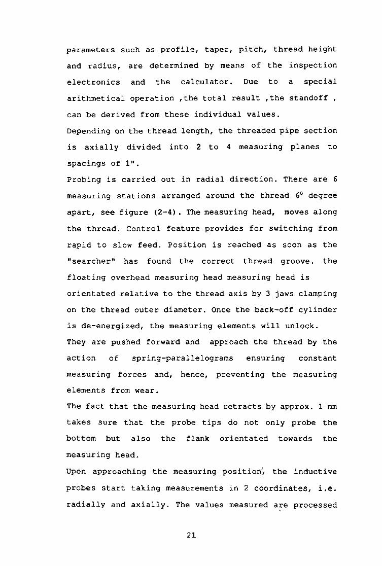
parameters such as profile, taper, pitch, thread height and radius, are determined by means of the inspection electronics and the calculator. Due to a special arithmetical operation ,the total result ,the standoff , can be derived from these individual values.Depending on the thread length, the threaded pipe section is axially divided into 2 to 4 measuring planes to spacings of 1”.Probing is carried out in radial direction. There are 6 measuring stations arranged around the thread 6° degree apart, see figure (2-4). The measuring head, moves along the thread. Control feature provides for switching from rapid to slow feed. Position is reached as soon as the "searcher" has found the correct thread groove, the floating overhead measuring head measuring head is orientated relative to the thread axis by 3 jaws clamping on the thread outer diameter. Once the back-off cylinder is de-energized, the measuring elements will unlock.They are' pushed forward and approach the thread by the action of spring-parallelograms ensuring constant measuring forces and, hence, preventing the measuring elements from wear.The fact that the measuring head retracts by approx. 1 mm takes sure that the probe tips do not only probe the bottom but also the flank orientated towards the measuring head.Upon approaching the measuring positionJ, the inductive probes start taking measurements in 2 coordinates, i.e. radially and axially. The values measured are processed
21

Figure (2-4)Arrngement of measuring station
22

by inspection electronics, the result are made up in the calculator, displayed on a VDU and printed out indicating the pipe NO. Upon completion of the measuring cycle, a pneumatic cylinder will pull back the measuring elements to come within the collision guard.The measuring head then returns to its initial position. The thread inspection machine, is made up of the following modules:
(1) - Basic machine with slide unit driven byservomotor.
( 2 ) - Rotary table with holding fixture for measuring head and counterbalance.
( 3 ) - Measuring head( 4 ) - Measuring head calibration station.( 5 ) - Electrical control with calculator and
printer [40].There exist a variety of instruments using different measurement techniques that attempt to characterize surface topography.The majority of these techniques may be classified according to the following criteria:
- Contact or non-contact.c- 2 Dimensional (2D) or 3 dimensional (3D).
- Analogue or digital.
The contact criteria is based upon whether the measuring probe is in physical contact with the test surface during
23

measurement.The most popular contact probe is the use of a diamond stylus ( either pyramidal or conical in shape ) with a radial tip of approximately 2 micrometre.An inherent limitation of contacting probes in the possibility of surface damage as the probe is drawn a cross the specimen. The degree to which this damage takes place is dependedt upon the geometry and loading of the stylus as well as the mechanical properties of the measurement surface [41].
24

CHAPTER THREE
3 - SCREW & SCREW MEASUREMENT
3-1 Definitions for use in mechanical engineering.
3.1.1 General.
(1)- Screw thread :
The ridge produced by forming, on the surface of a cylinder, a continuous helical or spiral groove of uniform section such that the distance measured parallel to the axis between two corresponding points on its contour is proportional to their relative angular displacement about the axis.
(2)- External (male) screw thread:
A thread formed on the external of a cylinder. See figure (3-1). The thread on a bolt is a typical example of an external screw thread.
(3)- Internal (female) screw thread:
A thread formed on the internal surface of a hollow cylinder. See figure (3-2) . The thread in nut, tapped
25

Crest
Half basic pitch
Root
1 \
Fitch point
\
\Axis ' I
diameterMinoriameter “A 110/ cylinder
Simple effectiv Fitch(pitch) diameter oylinder
Major diameter Major cylinder
Figure (3-1) External Screw Thread
26

Pitch line
Half basic pitch
Pitch point
Root
Crest
t \t I
v .\1
Minordiameter Minor cylinder
Simple effectiv Pitch cylinder
(pitch) cylinderMajor diameter
\ I \ J
Major cylinder
7igur* (3-2) Internal screw thread
27

holes or screw sockets are typical examples of internalscrew threads.
(4)- RIGHT-HAND SCREW THREAD:
A thread which, if assembled with a stationary mating thread, recedes from the observer when rotated in clockwise direction, see figure (3-3) .
(5)- LEFT-HAND SCREW THREAD:
A thread which,if assembled with a stationary mating thread, recedes from the observer when rotated in an anti-clockwise direction see figure (3-4) .
(6) - PARALLEL SCREW THREAD:
A thread formed on the surface of a cylinder. Seei
figure (3-1) and (3-2).
(7) - SINGLE-START SCREW THREAD:
A thread formed by a single continuous helicalgroove. See figures (3-3) and (3-4) .
(8) - MULTI - START SCREW THREAD:
A thread formed by a combination of two or morehelical grooves equally spaced along the axis. See figure (3-5).
3 - 1-2 Geometry of Screw Thread.
28

Figur« (3-3) Single-start screw thread
(Right hand)
Pitch
W V M V I
s , , , 1 1 iW W v
Figur« (3-4) Single-start screw thread (left hand)
29

b ' W V V N j
Pitch
Figure (3-5) Multi-start screw thread (Triple-start right hand)
30

(1)- FORM:
The shape o f one com p lete p r o f i l e o f th e th r e a d
between co rresp o n d in g p o i n t s , a t th e bottom o f
a d ja c e n t g r o o v e s , a s shown in a x i a l p la n e s e c t i o n .
(2)- BASIC FORM:
The t h e o r e t i c a l form on which th e d e s ig n forms fo r r
both th e e x te r n a l and i n t e r n a l th rea d s a r e b a s e d .
See f i g u r e s ( 3 - 6 ) , (3 -7 ) and ( 3 - 8 ) .
(3)- DESIGN FORM:
The forms o f th e e x te r n a l and i n t e r n a l th r e a d s in
r e l a t i o n to which th e l i m i t s o f t o l e r a n c e s a r e
a s s ig n e d . See f i g u r e (3 -6 ) .
(4)- FLANK:
Those p a r t s o f th e s u r f a c e on e i t h e r s i d e o f th e
th read th e i n t e r - s e c t i o n o f which w ith an a x i a l
p la n e are t h e o r e t i c a l l y s t r a i g h t l i n e s , s e e f i g u r e
( 3 - 7 ) .
(5)- CREST:
That p a r t o f th e s u r fa c e o f a th rea d which c o n n e c ts
a d ja c en t f la n k s a t th e to p o f th e r id g e . See
f i g u r e s (3 -1 ) and (3 -2 ) .
(6)- ROOT:That p a r t o f th e s u r fa c e o f a th rea d which c o n n e c ts
a d ja c e n t f la n k s a t th e bottom o f th e g r o o v e . See
f i g u r e s (3 -1 ) and ( 3 - 2 ) .
31

Oesign form Oesign form Base form (internal) (external)
Uhfied thread
Oesign form Design form Basic form (internal) (external)
Whitworth thread
Figure (3-6)Basic and design font of threads

Apex
Parrallel screw thread.
Figure (3-8) Basic form
33

(7)- INCLUDED ANGLE ( Angle Of Thread ) .
The a n g le betw een th e f la n k s and th e p e r p e n d ic u la r
t o th e a x i s o f th e thread measured in an a x i a l
p la n e s e c t i o n . See f ig u r e (3-7) .
(8)- FUNDAMENTAL TRIANGLE:
A triangle o f which two s i d e s r e p r e s e n t th e form o f
a t h e o r e t i c a l th read w ith sharp c r e s t and r o o t s ,
h av in g th e same p i t c h and f la n k a n g le s a s th e b a s i c
th rea d form and whose t h ir d s id e , or b a se i s
p a r a l l e l t o a g e n e r a to r o f th e c y l i n d e r on which the th rea d i s formed. See f ig u r e (3 -7 ) .
(9)- APEX:
The sharp c o rn er o f th e fundamental t r i a n g l e
o p p o s i t e to i t s b a se . See f ig u r e (3 -7 ) .
(10)- HEIGHT (OR DEPTH) OF THE FUNDAMENTAL TRIANGLE:
The d i s t a n c e , measured p e r p e n d ic u la r t o th e a x i s
from i t s apex t o i t s b a s e . See f i g u r e ( 3 - 7 ) .
(11)-BASIC TRUNCATIONsThe d i s t a n c e , measured p e r p e n d ic u la r t o th e a x i s ,
betw een th e b a s i c major or minor c y l i n d e r and th e
a d ja c e n t apex o f th e fundamental t r i a n g l e . See
f i g u r e ( 3 - 7 ) .
3-1-3 Pitch Of Screw Threads.

(1)- AXIS:
The a x i s o f the p i t c h c y l in d e r o f a screw th r e a d .
See f i g u r e s ( 3 - 1 ) , (3 -2 ) and ( 3 - 9 ) .
(2)- PITCH:
The d i s t a n c e , measured p a r a l l e l to th e a x i s , betw een
c o rr esp o n d in g p o in t s on a d ja c e n t th read forms in th e
same a x i a l p lan e s e c t i o n and on th e same s i d e o f th e
a x i s . See f ig u r e ( 3 - 3 ) , ( 3 - 4 ) , (3 - 5 ) , (3 -10) and
( 3 - 1 1 ) .
( 3 ) - LKADs
The d i s t a n c e , measured p a r a l l e l to th e a x i s , betw een
co rr esp o n d in g p o in t s on c o n s e c u t iv e o f th e same
th r ea d h e l i x in th e same a x i a l p la n e s e c t i o n and on
th e same s i d e o f th e a x i s . See f ig u r e ( 3 - 5 ) .
(4)- CUMULATIVE PITCH:
The d i s t a n c e , measured p a r a l l e l to th e a x i s o f th e
th r e a d between co rresp o n d in g p o in t s on any two
th r e a d forms whether in th e same a x i a l p la n e or n o t .
(5)- PITCH CYLINDER:An im aginary c y l in d e r , c o - a x i a l w ith th e th read ,
w hich i n t e r s e c t s th e s u r fa c e o f p a r a l l e l th read in
such a manner th a t th e i n t e r c e p t on a g e n e r a to r o f
th e c y l i n d e r between th e p o in t s where i t m eets th e
o p p o s i t e f la n k s o f the th r ea d groove i s equal t o
h a l f th e b a s i c o f the th r e a d . See f i g u r e s (3 -1) and
35

Length of engagement
Figure (3-9)
36

Depth of thread
^Major crest trunction
T , Pitch line
of thread Pitch
Addendum
Figure (3-10)Design form (external thread)
Figure (3-11) Design form
(internal thread)
37

( 3 - 2 ) .
(6)- PITCH LINE:
The g e n e ra to r o f th e p i t c h c y l i n d e r . See f i g u r e s
( 3 - 1 ) , ( 3 - 2 ) , (3 -10) and ( 3 - 1 ) .
(7)- PITCH POINT:
The p o in t where th e p i t c h l i n e i n t e r s e c t s th e f la n k
o f th e th r ea d . See f i g u r e s ( 3 - 1 ) , ( 3 - 2 ) .
(8)- LEAD ANGLE:
On a p a r a l l e l th read th e a n g le made by th e h e l i x o f
th e thread a t th e p i t c h w ith a p la n e p e r p e n d ic u la r
t o th e a x i s .
3-1-4 Diameter Of Screw Threads.
(D- MAJOR CYLINDER:
An im aginary c y l i n d r i c a l s u r fa c e which j u s t to u c h e s
th e c r e s t s o f an e x te r n a l th read or the r o o t s o f an
in t e r n a l th r ea d . See f i g u r e s (3 -1 ) and (3 -2 ) ./
(2) - MINOR CYLINDER sAn im aginary c y l i n d r i c a l s u r fa c e which j u s t to u c h e s
th e r o o ts o f an e x te r n a l th rea d or th e c r e s t s o f an
i n t e r n a l th r ea d . See f i g u r e s (3 -1 ) and (3 -2 ) .
(3)- MAJOR DIAMETER sThe diam eter o f th e major c y l in d e r o f a p a r a l l e l
38
th read , in a s p e c i f i e d p la n e normal to th e a x i s .
See f i g u r e s (3 -1 ) and (3 -2 ) .
(4)- EFFECTIVE (OR PITCH) DIAMETER:
The d iam eter o f th e p i t c h c y l in d e r o f a p a r a l l e l
thread in a s p e c i f i e d p la n e normal t o th e a x i s . See
f i g u r e s (3 -1 ) and (3-2) .
(5)- VIRTUAL EFFECTIVE DIAMETER:
The e f f e c t i v e d iam eter o f an im aginary th r e a d o f
p e r f e c t p i t c h and f la n k a n g le , h a v in g th e f u l l depth
o f f la n k s , but c l e a r a t th e c r e s t s and r o o t s , which
would j u s t a ssem b le w ith th e a c tu a l th rea d ov er th e
p r e s c r ib e d le n g th o f engagem ent.
3-1-5 Assembly of Screw Threads.Definitions o f terms r e l a t i n g to assem b ly o f screw
th r e a d s are g iv e n m BS: 2517, [25] .
3-2 Type of Screw Threads
E leven t y p e s , or s e r i e s , o f th r ea d s a re o f commercial
im portance, s e v e r a l h av in g e q u iv a le n t s e r i e s m th e
m e tr ic system and u n i f i e d sy s tem s:
( 1 ) - C o a r se -th r ea d s e r i e s (UNC and NC). For g e n e r a l
u se where not s u b je c te d t o v i b r a t i o n .
(2)- F in e - th r e a d s s e r i e s (UNF and N F ). For most
au to m o tive and a i r c r a f t work.
(3)- E x t r a - f in e s e r i e s (UNEF and NEF) . For u se w ith
39

t h in - w a l l e d m a te r ia l or a maximum number o f
th r ea d s a re req u ire d in a g iv e n l e n g t h .
( 4 ) - E ig h t - th r e a d s e r i e s (8 UN and 8 N) . E igh t th rea d s
per in c h fo r a l l d ia m eters from 1 through 6 in .
I t i s u sed p r im a r i ly fo r b o l t s on p ip e f la n g e s
and c y l in d e r - h e a d s tu d s where an i n i t i a l t e n s io n
must be s e t up to r e s i s t steam o r a i r p r e s s u r e s .
( 5 ) - T w e lv e -th r ea d s e r i e s (12 UN and 12 N) . Twelve
th r e a d s p er in c h fo r d ia m eter fo r 1/2 through 6
i n . I t i s not used e x t e n s i v e l y .
(6 ) - S ix t e e n - t h r e a d s e r i e s (16 UN and 16 N) . S ix t e e n
th r e a d s p er in ch for d ia m e ter s from 3 /4 through
6 i n . I t i s used fo r a wide v a r i e t y o f
a p p l i c a t i o n s th a t r e q u ir e a f i n e th r e a d .
( 7 ) - American Acme th rea d . See f i g u r e ( 3 - 1 2 ) .
(8 ) - B u t t r e s s th rea d .
( 9 ) - Square th r e a d .
(10)- 29° Worm th r ea d . These l a s t fou r o f th e th rea d s
a re u sed p r im a r i ly in t r a n s m i t t in g power and
m otio n .
(11)- American standard p ip e th r e a d . T h is th r ea d ,
shown in f ig u r e (3 -1 2 ) , i s th e s ta n d a rd tap p ered
th rea d u sed on p ip e j o i n t s in t h i s c o u n tr y .
The ta p e r on a l l p ip e th read s i s 3 /4 i n . per f o o t .
The u n i f i e d th r e a d s are a v a i la b l e in a c o a r s e (UNC and
NC) , f i n e (UNF and NF) , e x t r a - f i n e ( UNEF and NEF) , and
th r e e -" p i t c h ■ (8 , 12 and 16) s e r i e s , th e number o f
th r ea d s p er in c h b e in g a c co r d in g t o an a r b i t r a r y
d e te r m in a t io n b a sed on th e major d ia m e te r .
40

American Acme Thread Square Thread
American standard pipr thread Butress Threadr — -------------- i ^ p i p i 45*
T(a a a / v v w ^a ^ ^
3D/429 Degree Worm Thread
Figure (3-12) Special thread forms.
41

Many n a t io n s have now ad op ted ISO th rea d s i n t o t h e i r
n a t io n a l s ta n d a r d s . B e s id e s m e t r ic ISO th r e a d s , t h e r e are
a l s o in c h -b a sed ISO th r e a d s , namely th e UN s e r i e s w ith
which p e o p le in th e U n ite d S t a t e s , Canada, and Great
B r i t a in are f a m i l i a r .
ISO o f f e r s a wide range o f m e tr ic s i z e s . I n d iv id u a l
c o u n tr ie s have th e c h o ic e o f a c c e p t in g a l l or a s e l e c t i o n
o f th e ISO o f f e r i n g s . For a com parison o f u n i f i e d and ISO th r ea d s s i z e s s e e t a b l e ( 3 - 1 ) , [ 7 ] .
The b ig g e s t d i f f e r e n c e betw een th e UN and ISO s e r i e s i s
th e number o f th rea d s p er u n i t l e n g t h . The d e s ig n
p r o f i l e s fo r th e UN and ISO a r e shown in f i g u r e (3 -1 3 ) .
W hile many f e a t u r e s a re th e same, p r in c ip a l d i f f e r e n c e
a re r e la t e d to b a s i c s i z e , t h e m agnitude and a p p l i c a t i o n
o f a l low an ce and t o l e r a n c e s , and thread d e s i g n a t i o n s . For
th e UN th read , a f l a t r o o t i s s p e c i f i e d fo r e x t e r n a l
th r e a d s; however in p r a c t i c e , product th rea d s a re
produced w ith p a r t i a l or c o m p le te ly rounded c r e s t s .
In th e i n t e r n a l UN th r e a d s , i t i s n e c e ssa r y t o p r o v id e
fo r some th r ea d in g t o o l c r e s t wear. The ISO forms, in
f i g u r e (3 -1 3 ) , are shown w ith and w ith o u t an a l lo w a n c e on
th e e x te r n a l th rea d , and t o o l wear, a s in d ic a t e d by a
form c le a r a n c e , i s p e r m i s s i b l e [ 4 2 ] .
3-3 Methods Of Manufacturing Threads.
External th r ea d s may be produced by th e f o l lo w in g
m anu factu ring p r o c e s s e s :
42

Comparison between selection Unified and ISO Threads Unified ISO
TABLE ( 3 - 1 )
D Thread per in. Thread per in.Number in. mm UNC UNF Coarse Fnie#2 2.18 56 64 M2X.4#4 2.84 40 48 M2X.45#8 4.17 32 36 M4X.7#10 4.82 24 28 M5X.8
1/4 in. 6.35 20 28 M6xl1/2 in. 12.7 13 20 M12X1.75 M12X1.253/4 in. 10.05 10 16 M20X2•5 M20X1.51 in. 25.4 8 14 M2 4X3 M2 0X2

ISO STANOARO
tU
• Mm drugrt maj©« d*am*tt* »SO t» v c pro«*»*
Mu mi/xy Ma* det*qn miAOf d»**neter
Am» o* thread
Rounded ro o t COntOwr
pcfmimtH*
Thread W ithout an Allowance
M in major diameter
'SO bave prof**eI
I V Rounded roo t. I c o n t o u r p « r m t0*b*e
M a i m m or d i a m e t e r / \ M a * d e v ç n « u n o r d i a m e t e r
Aw* of threadW ith an A llowance on Esternai Thread
U o I2 S H
f T0675/y 0 3 7 5 / 1
U N S T A N D A R D
Rounded ro o t op tiona lFlank« to be straight diameter
beyond 0 7SH fro m «harpape« o f ro o t . , . J
A k h o* esternai thread
Figure (3-13)Design profile of iso and UM thread standard
( 1 ) - C u tt in g to shape on e n g in e l a t h e .
( 2 ) - Using d ie and stocK (m anual).
( 3 ) - Automatic d ie head ( t u r r e t l a t h e ) .
( 4 ) - M i l l in g machine.
( 5 ) - Threading machine ( p la in or a u to m a t ic ) .
(6 )- R o l l in g between d i e s ( f l a t or c i r c u l a r ) .
( 7 ) - D ie c a s t i n g .
(8 )- G rind ing.
I n te r n a l th read s may be produced by:
( 1 ) - C u tt in g to shape on an e n g in e l a t h e .
( 2 ) - U sing tap and h o ld e r .
( 3 ) - Automatic c o l l a p s i b l e t a p .
( 4 ) - M il l in g machine.
( 5 ) - Screw broach.
3-3-1 Cutting screw tlbireadLs on & lathe«
The l a t h e i s u s u a l l y s e l e c t e d when o n ly a few
th rea d s are to be cut or when s p e c i a l forms are d e s i r e d
[42] .
C u tt in g screw threads on a l a t h e i s a s low , r e p e t i t i o n s
p r o c e s s th a t r e q u ir e s c o n s id e r a b le o p e r a to r s k i l l . The
c u t t i n g speeds u s u a l ly employed a re from one t h i r d t o on
h a l f o f r e g u la r speeds to e n a b le th e o p e r a to r to have
t im e to m anipulate th e c o n t r o l s and to en su re b e t t e r
c u t t i n g . The c o s t per p a r t can be h ig h , which e x p la in s
why o th e r methods are used when e v e r p o s s i b l e [7] .
45

3-3-2 Taps and Dies.
Taps are used p r i n c i p a l l y fo r th e manual p r o d u c t io n
o f i n t e r n a l th r e a d s . The t o o l i t s e l f i s a hardened p i e c e
o f carbon or a l l o y s t e e l resem b lin g a b o l t , w ith f l u t e s
cu t a lo n g th e s i d e to p ro v id e th e c u t t i n g ed g e .
For hand ta p p in g , t h e s e are fu r n ish e d in s e t s o f th r e e
fo r each s i z e s . In s t a r t i n g th e th r ea d , th e ta p e r tap
sh o u ld be used , s i n c e i t in s u r e s s t r a i g h t e r s t a r t i n g and
more gradual c u t t i n g a c t io n on th e th r e a d s . I f i t i s a
through h o le , no o th e r tap i s n eed ed . For c l o s e d o r b l i n d
h o le s w ith th rea d s to th e very bottom , th e ta p e r , and
bottom ing ta p s sh ou ld a l l be used in th e ord er named.
Other ta p s are a v a i la b l e and are named a c c o r d in g to th e
k in d o f th read th ey are to c u t .
To cu t e x te r n a l th read , th e most common method i s by th e
a d ju s t a b le d i e . I t can be made to cu t e i t h e r s l i g h t l y
u n d e r s iz e or o v e r s i z e . When used fo r hand c u t t i n g , th e
d ie i s h e ld in a d ie s to c k which p r o v id e s th e n e c e s s a r y
le v e r a g e to turn th e d ie in making th e c u t .
For s u c c e s s f u l o p e r a t io n o f e i t h e r ta p s or d i e s ,
c o n s id e r a t io n must be g iv en to th e n a tu re o f th e m a te r ia l
to be th read ed . No t o o l can be made t o work s u c c e s s f u l l y
fo r a l l m a t e r ia l s .
The shape and a n g le o f th e c u t t i n g fa c e a l s o in f l u e n c e
th e perform ance. Another im portant f a c t o r i s proper
l u b r i c a t i o n o f th e t o o l during th e c u t t i n g o p e r a t io n ;
t h i s in s u r e s lo n g e r l i f e o f th e ed g es and r e s u l t s in;
sm oother t h r e a d s .
46

Taps and d ie s can a l s o be used in the m achine c u t t i n g o f
th r e a d s . Because o f th e n a tu re o f th e c u t t i n g o p e r a t io n ,
th e y must be h e ld in s p e c i a l h o ld e r , so d e s ig n e d th a t th e
tap or d ie can be withdrawn from th e work w ith o u t in j u r y
t o th e t h r e a d s . T h is i s f r e q u e n t ly a c co m p lish ed by
r e v e r s in g th e r o t a t i n g o f th e t o o l or work a f t e r th e cu t
has been made.
In small-production work on a t u r r e t l a t h e , th e ta p i s
h e ld by a s p e c i a l h o ld e r , which p r e v e n ts th e tap from
tu r n in g as th e th r ea d a re c u t . Near th e end o f th e cu t
th e t u r r e t h o ld in g th e t o o l i s s to p p ed , and th e tap
h o ld e r c o n t in u e s to advance u n t i l i t p u l l s away from a
s to p p m a s u f f i c i e n t amount to a l lo w th e ta p h o ld e r to
r o t a t e w ith th e work. The r o t a t i o n work o f t h e work i s
then r e v e r se d and, when the tap h o ld e r i s w ithdraw n, i t
i s a ga in engaged w ith th e s to p and h e ld u n t i l th e work i s
r o t a t e d from th e tap .
E x tern a l th r ea d s can be cu t w ith a d ie u t i l i z i n g t h i s
same procedure a lth o u g h in most c a s e s such th r e a d s a re
cu t w ith s e l f - o p e n i n g d i e s .
3-3-3 Thread Chasing
In p r o d u c t io n work s e l f - o p e n i n g d i e s and
c o l l a p s i b l e ta p s are u sed to e l im in a t e back t r a c k in g o f
th e t o o l and t o sa v e t im e . The t o o l s have i n d iv id u a l
c u t t e r d i e s , known as c h a s e r s , mounted m a p p r o p r ia te
h o ld e r , which a r e c a p a b le o f adjustm ent or r e p la c e m e n t .
With c h a se r s more a c c u r a te work r e s u l t s , th e c u t t e r s can
47

be kept in proper a d ju stm en t , and th e r e i s no danger o f
damaging th e cu t th rea d as th e t o o l i s w ithdrawn.
In some c a s e s th e t o o l i s h e ld s t a t i o n a r y and th e work
r e v o lv e s in o th e r s th e r e v e r s e p roced u re may be u se d . A l l
p r e c i s i o n screw s r e q u ir e a l e a d screw fe e d to o b ta in
a c c u r a c y .
Two ty p e s o f a u tom atic d i e heads a re u sed . In one c u t t e r s
or c h a se r s are mounted t a n g e n t i a l l y . In th e o th e r th e y
are in a r a d ia l p o s i t i o n . R a d ia l c u t t e r s can be changed
qu ick ly ? c o n se q u e n t ly , th e y a r e used fo r th r e a d in g
m a t e r ia l s th a t a r e hard to c u t . The d i e head commonly
used on most t u r r e t l a t h e s i s o f s t a t io n a r y ty p e . The
work r o t a t e s and th e c h a se r s open a u t o m a t ic a l ly a t th e
end o f th e cu t so th a t th e y can withdraw from th e work
w ith o u t damage.
In th r e a d in g m ach ines, th e d i e s r o t a t e and th e work i s
fed to them, but o th e r w is e th e o p e r a t io n i s th e same.
3 - 3-4 Tapping Machine
Although much ta p p in g i s done on d r i l l p r e s s e s
equipped w ith some form o f ta p p in g a ttach m en t, most
p r o d u ct io n ta p p in g i s done on s p e c i a l l y c o n s t r u c t e d
a u to m a tic m ach ines. Nuts t o be th rea d ed are fe d from an
o s c i l l a t i n g hopper to th e w orking p o s i t i o n ; th e s p i n d le s
are r e v e r s e d a t d ou b le th e ta p p in g speed; and th e n u ts
are d is c h a r g e d to in d iv id u a l c o n t a i n e r s .
A common typ e o f ta p p in g m achine has m u l t i - s p i n d l e
arrangem ent p r o v id ed w ith ta p s h a v in g e x tr a lo n g sh a n k s .
48

The ta p i s advanced through th e nut by th e l e a d screw
and, upon co m p le t io n o f th e th r e a d in g , c o n t in u e s downward
u n t i l th e nut i s r e l e a s e d .
The s p i n d le then r e tu r n s to i t s upper p o s i t i o n w ith th e
tapp ed nut on i t s shank. When th e shank has been f i l l e d/
w ith n u t s , th e tap i s removed and th e n u ts a r e em ptied
i n t o a c o n t a in e r .
3-3-5 Thread M i l l i n g .
Accurate th r ea d s o f la r g e s i z e , b o th e x t e r n a l and
i n t e r n a l , can be cu t w ith stan dard or h o b -ty p e c u t t e r s .
For lo n g e x te r n a l th r e a d s , a th r e a d in g machine s i m i l a r in
ap p earan ces to a l a t h e i s u sed . Work i s mounted e i t h e r in
a chuck or betw een c e n tr e s , th e m i l l i n g a ttach m en t b e in g
a t th e r e a r o f th e m achine.
In c u t t i n g a long screw , a s i n g l e c u t t e r i s mounted in
th e p la n e o f th e th read a n g le and fe d p a r a l l e l to the
a x i s o f th e thread ed p a r t . The fe e d ( f ) in th rea d m i l l i n g
i s e x p r e s s e d as th e c u t t e r advance per t o o t h , or
m i l l i m e t r e per c u t t e r to o th by th e f o l lo w in g form ula:
f = 3.14 d.s/n.N (3 - 1)
From t h i s e x p r e s s io n i t i s e v id e n t th a t th e c u t t e r loa d
p e r t o o t h , which v a r i e s d i r e c t l y w ith th e f e e d , can be
changed by v a r y in g th e c u t t e r sp eed , work sp eed , or
number o f t e e t h in th e c u t t e r .
T h is p e r m its red u c in g th e load on th e c u t t e r t e e t h so
49

th a t deep th r e a d s can be cu t in one p a s s . For s h o r t
e x te r n a l th r e a d s , a s e r i e s o f s i n g l e - t h r e a d c u t t e r are
p la c e d s i d e - b y - s i d e and are made as one c u t t e r , h a v in g a
w idth s l i g h t l y more than th a t o f th e th read t o be c u t .
The c u t t e r i s fe d r a d i a l l y i n t o th e work to th e proper
depth and, w h i le r o t a t i n g a l i t t l e o ver one r e v o l u t i o n ,
com p letes th e m i l l i n g o f th e th r ea d . Proper le a d i s
o b ta in ed by a fe e d mechanism which moves th e c u t t e r
a x i a l l y w h i le i t i s c u t t i n g .
M i l l in g m achines o f th e p la n e ta r y - ty p e a re a l s o used fo r
mass p r o d u c t io n o f sh o r t i n t e r n a l or e x t e r n a l th r e a d s .
The m i l l i n g head c a r r y in g the hob i s r e v o lv e d
e c c e n t r i c a l l y about the r i g i d l y h e ld work, which i s
r o ta t e d s im u lta n e o u s ly on i t s own a x i s . I t i s advanced by
means o f a l e a d screw fo r a s u f f i c i e n t d i s t a n c e to
produce th e th r ea d [4 2 ] .
3-3-6 Thread Rolling
Thread r o l l i n g i s used to produce th r ea d s in
s u b s t a n t i a l q u a n t i t i e s . This i s a c o ld - fo r m in g p r o c e s s
o p e r a t io n ,in which th e th read s are formed by r o l l i n g a
th rea d b lan k betw een hardened d ie s th a t ca u se th e m eta l
to f lo w r a d i a l l y i n t o the d e s ir e d sh ap e . B ecause no m eta l
i s removed in th e form o f c h ip s , l e s s m a t e r ia l i s
r e q u ir e d , r e s u l t i n g in s u b s t a n t ia l s a v in g s .
In a d d i t io n , b eca u se o f th e c o ld w orking, th e th rea d s
have g r e a t e r s t r e n g t h than cu t th r e a d s , and a sm oother,
h ard er , and more w e a r - r e s i s t a n t s u r fa c e i s o b ta in e d . In
50

a d d i t io n , th e p r o c e s s i s f a s t , w ith p ro d u ct io n r a te o f
one per secon d b e in g common.
The q u a l i t y o f c o l d - r o l l e d (or f l u t e l e s s - t a p p e d )
p ro d u cts i s c o n s i s t e n t l y good and tap l i f e i s g r e a t e r
than th a t o f HSS machine t a p s .
C h ip le s s o p e r a t io n s are c le a n e r and th e r e i s a s a v in g s in
m a te r ia l (15% to 20% sa v in g in b lank s to c k w e igh t i s
t y p i c a l ) , [ 7 ] .
F ig u re (3 -14 ) i l l u s t r a t i n g s to c k m a te r ia l sa v in g o f
r o l l e d th r ea d s ov er cu t th r e a d s . A lso f i g u r e ( 3 - 1 5 ) , th e
blan k d ia m e ter s fo r both r o l l e d and cu t th r ea d s a r e
in d ic a t e d fo r s e v e r a l th rea d s [ 4 2 ] . Thread r o l l i n g i s
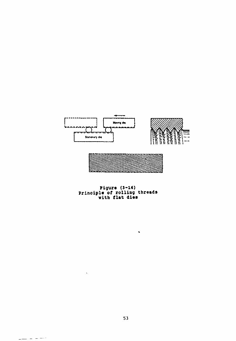
done by fou r b a s i c m ethods.
The s im p le s t o f t h e s e employs one f ix e d and one movable
f l a t r o l l i n g d i e , as i l l u s t r a t e d in f ig u r e (3-16) . A f te r
th e b lank i s p la c e d in p o s i t i o n on th e s t a t io n a r y d i e ,
movement o f th e moving d ie ca u ses th e b lank to be r o l l e d
betw een th e two d i e s and th e m eta l in th e b lank i s
d is p la c e d t o form th e th r e a d s . As th e b lank r o l l s , i t
moves a c r o s s th e d ie p a r a l l e l w ith i t s l o n g i t u d in a l a x i s .
P r io r to th e end o f th e s to k e o f th e moving d i e , th e
blank r o l l s o f f th e end o f th e s t a t io n a r y d ie , i t s th rea d
b e in g com p leted .
One ob v iou s c h a r a c t e r i s t i c o f a r o l l e d th rea d i s th a t i t s
major d iam eter alw ays i s g r e a te r than th e d iam eter o f th e
b la n k . When an a c c u r a te c l a s s o f f i t i s d e s i r e d , th e
d iam eter o f th e b lank i s made about 0.002 in . la r g e r than
th e t h r e a d - p i t c h d ia m eter .
I f i t i s d e s i r e d to have th e body o f a b o l t la r g e r than
51

Cut Thrutf RoHtd Thr«*d
Figur» (3-14)Stock material saving of roled
threads over out threads
Figure (3-15)Blank diameter for rolled
and out threads
52
» . s v mH,«-rW
0*
Figur« (3-1«) principi« of rolling threads
with flat di«s
53

th e o u t s id e d ia m eter o f th e r o l l e d th r ea d , th e b lank or
th e th read i s made sm a l le r than th e body.
Thread r o l l i n g can be done w ith c y l i n d r i c a l d i e s . There
are t h r e e - r o l l methods commonly employed on t u r r e t l a t h e s
and screw m ach ines. Two v a r i a t i o n a re u sed . In one, th e
r o l l s are r e t r a c t e d and th e b lan k i s p la c e d in p o s i t i o n .
They then move inward r a d i a l l y , w h i le r o t a t i n g , to form
th e th rea d .
More commonly th e th r e e r o l l s a r e c o n ta in e d in a s e l f -
opening d ie head s im i la r t o th e c o n v e n t io n a l ty p e u sed
fo r c u t t i n g e x te r n a l t h r e a d s . The d i e head i s fe d o n to
th e b lank l o n g i t u d i n a l l y and forms th e th r e a d
p r o g r e s s i v e l y as th e b lank r o t a t e s . With t h i s p ro ced u re ,
as in th e c a s e o f cu t th r e a d s , th e innerm ost 1 .5 t o 2
th rea d s are not formed to f u l l depth b ecau se o f th e
p r o g r e s s iv e a c t io n o f th e r o l l e r s .
The t w o - r o l l method i s commonly employed f o r
a u t o m a t ic a l ly producing la r g e q u a n t i t i e s o f e x t e r n a l l y
thread ed p a r t s up to 6 i n . d iam eter and 20 i n . in l e n g t h .
The p la n e ta r y typ e machine i s fo r mass p r o d u c t io n o f
r o l l e d th read on d iam eter up to 1 i n .
Not o n ly i s th read r o l l i n g v e ry e co n o m ic a l, but th e
th r ea d s are e x c e l l e n t a s to form and s t r e n g t h . [7] .
F o llo w in g a re some o f th e a d v a n ta g es o f th e th r ea d
r o l l i n g p r o c e s s :(
( 1 ) - Improve t e n s i l e , sh ea r , and f a t i g u e s t r e n g t h .
( 2 ) - Smooth s u r fa c e f i n i s h o f 0 .1 to 0 .8 um.
( 3 ) - C lo se a ccu racy m a in ta in e d .
( 4 ) - L ess m a te r ia l r e q u ir e d .
54

( 5 ) - Cheaper m a t e r ia l s may o f t e n be used owing to
improvement o f p h y s i c a l p r o p e r t i e s .
(6 )- High p r o d u ct io n r a t e .
( 7 ) - A wide v a r i e t y o f th rea d forms p o s s i b l e .
L im ita t io n s o f th e th rea d r o l l i n g p r o c e s s in c lu d e :
( 1 ) - Blank t o l e r a n c e must be c l o s e , s i n c e no m eta l i s
removed.
( 2 ) - Not econ om ica l fo r sh o r t run j o b s .
( 3 ) - Only e x te r n a l th r e a d s can be r o l l e d .
( 4 ) - M a ter ia l h av in g a h ard n ess e x c e e d in g R ockw ell C 37
cannot be r o l l e d [ 4 2 ] .
3-3-7 Thread Grin di ng .
Grinding can produce v ery a c c u r a te th r e a d s , and i t
a l s o p erm its th r ea d s to be made on hard m a t e r i a l s . Three
b a s i c methods a re u sed . C e n tr e - ty p e g r in d in g w ith a x i a l
f e e d i s th e most common method, b e in g s i m i la r to c u t t i n g
a th read on a l a t h e .
A shaped g r in d in g w heel r e p la c e s th e s i n g l e - p o i n t t o o l .
U s u a l ly , a s i n g l e - r i b b e d g r in d in g w heel i s employed, but
m u lt ip le - r ib b e d w h ee ls a re used o c c a s i o n a l l y .
The g r in d in g w h ee ls a re shaped by s p e c i a l diamond
d r e s s e r s or by cru sh d r e s s in g and must be i n c l i n e d t o th e
h e l i x a n g le o f th e th r e a d . Wheel sp eed s a re in th e h ig h
ran g e . S e v e ra l p a s s e s a re u s u a l ly r e q u ir e d t o co m p lete
th e th rea d . C e n tr e - ty p e in fe e d th r ea d g r in d in g i s
s i m i la r t o m u lt ip le - fo r m m i l l i n g m th a t a m u l t i p l e -
r ib b e d w h e e l , a s w ide a s th e le n g t h o f th e d e s i r e d
55

th read , i s u sed .
The w heel i s fe d inward r a d i a l l y to f u l l th r e a d d ep th ,
and th e th read b lank i s then turned through about 1 .5
tu rn s as th e g r in d in g w heel i s fe d a x i a l l y a l i t t l e more
than th e w id th o f one th r ea d .
c e n t r e - l e s s th rea d g r in d in g , i s used fo r making h e a d le s s
s e t screw . A p r o d u c t io n r a te o f 60 to 70 screw s o f 1 .5
in ch le n g th p er m inute i s p o s s i b l e [ 7 ] , [ 4 2 ] .
The c r e s t forms r e s u l t i n g from d i f f e r e n t p r o d u c t io n
methods are i l l u s t r a t e d m f ig u r e ( 3 - 1 7 ) , [ 4 3 ] .
3 -4 E rrors o f screw th r ea d s
A screw th rea d has se v en e le m e n ts , e r r o r on any one
o f which may be s u f f i c i e n t to r e j e c t work w hich ought to
p a s s . These e le m en ts are:
(1)- Major d ia m eter .
(2)- Minor diameter.
(3)- Effective (or pitch) diameter.
(4)- P i t c h .
(5)- Flank angles.
(6)- Radius at crest.
(7)- Radius at root.
Of t h e s e , e f f e c t i v e d ia m eter , p i t c h and f la n k a n g le a r e ,
perhaps , th e most c r i t i c a l , and are th o s e w hich e r r o r s
most f r e q u e n t ly o c c u r .
3-4-1 Effective Diameter
56

I
(C)- Typical crest on cut thread bolt
Figure (3-17)
Crest forms resulting from different prodution methods
57

The im portance o f accu racy in th e e f f e c t i v e
diam eter o f a screw thread becomes e v id e n t when i t i s
r e a l i z e d th a t e r r o r in t h i s d iam eter d e term in e to a la r g e
e x te n t th e amount o f " play" betw een m ating screw
t h r e a d s .
3-4-2 Pitch
The e f f e c t o f error in p i t c h upon th e f i t t i n g
to g e th e r o f screw thread s depends not so much on th e
in d iv id u a l e r r o r s in th e sp a c in g o f th e a d ja c e n t tu rn s o f
th read as on th e a d d i t iv e e f f e c t o f t h e s e e r r o r s , which
i s known as th e cu m u la tive e r r o r .
The cu m u la tive p i t c h erro r o f a screw th read i s th e e rr o r
o f i t s e f f e c t i v e d iam eter h e l i x , measured p a r a l l e l t o th e
a x i s o f th e screw th read , from i t s c o r r e c t p o s i t i o n in
r e l a t i o n to a f i x e d datum p la n e normal to th e a x i s o f
th r ea d . F igu re (3-18) i s a c h a r t showing th e c u m u la t iv e
e rr o r a lon g th e whole le n g th o f th e h e l i x o f a th r e a d . A
ch a rt o f th e cu m u la tive p i t c h e r r o r may e x h i b i t c e r t a i n
c h a r a c t e r i s t i c s depending on th e n a tu re o f th e e r r o r and
i t s c a u se s .
The e r r o r may be o f a r e p e t i t i v e or p e r io d ic n a tu r e , i . e .
i t may vary in m agnitude a lon g th e le n g t h o f th rea d and
recur a t r e g u la r i n t e r v a l s . I f th e e r r o r r e c u r s a t
i n t e r v a l s o f one turn then th e screw i s s a id to be
" drunken ".
P itc h e r r o r s o f a p e r io d ic n a tu re are u s u a l l y due to some
f l o a t or f a u l t s m th e r o t a t in g members o f th e machine on
58

Max. cumulative error
Figure (3-18)Chart of cumulative pitch error
of periodic c h a r a c ter
Max. cumulative error
Figure (3-19)Chart of cumulative pitch error measured
at interavel of one pitch
59

which th e screw th read i s produced. Common so u r c e s o f
such e r r o r s a re la c k o f t r u th in th e t h r u s t - c o l l a r o f th e
le a d screw and i t s a butment fa c e , or e c c e n t r i c mounting
o f th e g ea rs m th e t r a i n c o n n e c t in g th e le a d screw and
h ead stock s p i n d le .
D e fe c t s o f b o th t h e s e ty p e s produce s in u s o i d a l p i t c h
e rr o r c u r v e s . I f more than one gear i s e c c e n t r i c th e
p i t c h e rr o r curve w i l l be th e r e s u l t a n t o f a number o f
s in u s o id a l cu rv es and may be complex in c h a r a c te r as
shown in f i g u r e ( 3 - 1 8 ) .
The ch art o f th e cu m u la tiv e p i t c h e rr o r o f a screw th read
may i n d ic a t e th a t th e p i t c h e rr o r v a r i e s i r r e g u l a r l y
a lon g th e le n g th o f th e th r ea d . Such e r r o r s may be due to
o th e r f a u l t s in th e machine on which th e screw th read was
produced, or p o s s i b l y to an i r r e g u la r c u t t i n g a c t i o n due
to n o n -u n ifo r m ity o f th e m a te r ia l o f th e screw th r e a d .
Errors o f a p e r io d ic or i r r e g u la r ty p e such as th o s e
d e sc r ib e d above may be superim posed on a cu m u la t iv e p i t c h
erro r o f a more or l e s s uniform n a tu re cau sed , fo r
example, by an a x i a l e x te n s io n or c o n t r a c t io n o f th e
screw due to hard en in g , e r r o r s m th e p i t c h o f th e le a d
screw or la c k o f s t r a i g h t n e s s o f th e ways o f th e s a d d le .
To o b ta in a com p lete knowledge o f th e cu m u la tiv e p i t c h
e rr o r o f a screw th read n e c e s s i t a t e s m easuring th e e rr o r/
o f th e e f f e c t i v e d iam eter h e l i x o f th e th rea d from one
end o f th e th rea d to th e o th e r . I t i s r a r e ly c o n v e n ie n t
or p r a c t i c a b l e to do t h i s , however and i t i s u su a l to
measure th e e r r o r s a t i n t e r v a l s o f w hole p i t c h e s a lo n g a
l i n e p a r a l l e l to th e a x i s o f th e th r e a d .
60

Where a p p r e c ia b le p i t c h e r r o r s o f a p e r io d ic or e r r a t i c
n atu re are p r e se n t in a th rea d t h i s method o f measurement
does not p ro v id e a tru e gu id e to th e f u l l m agnitude o f
th e p i t c h e r r o r . Thus, i f measurements were made a t
i n t e r v a l s o f s i n g l e tu rn s o f th e th rea d o f th e screw to
which f ig u r e (3-18) r e f e r s , th e r e s u l t would be a ch a r t
as in f ig u r e (3-19) , where th e tr u e c h a r a c te r o f th e
e r r o r i s no lo n g e r seen and th e maximum cu m u la tive e r r o r .
3-4-3 Error in pitch in relation to effective di am et er .
It i s im portant to r e a l i z e th a t any e r r o r m
p i t c h needs to be compensated by a co rresp o n d in g , but
ind ep en dent, e r r o r m e f f e c t i v e d ia m e ter . Thus, i f an
o th e r w is e p e r f e c t e x te r n a l screw has p i t c h e r r o r , i t w i l l
not screw i n t o a p e r f e c t i n t e r n a l screw o f th e same
nominal s i z e .
I t can be made to do so by red u c in g i t s e f f e c t i v e
d iam eter and so making th e th r ea d s s l i g h t l y t h i n . Thus,
i f any e r r o r in p i t c h i s p r e s e n t , th e " v i r t u a l "
e f f e c t i v e d iam eter o f an i n t e r n a l screw w i l l be g r e a t e r ,
and o f an e x te r n a l screw l e s s , than i t s a c tu a l (s im p le)
e f f e c t i v e d ia m eter . The e q u iv a le n t d i f f e r e n c e in
e f f e c t i v e d iam eter n e c e s s a r y to com pensate fo r any g iv e n
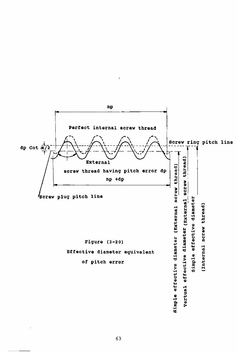
p i t c h e r r o r may be determ ined as f o l lo w s :
Suppose th e f u l l and th e d o t te d o u t l i n e s in f i g u r e (3 -20)
r e p r e s e n t r e s p e c t i v e l y an o th e r w is e p e r f e c t e x t e r n a l
screw h av in g a p i t c h erro r (dp) and a p e r f e c t i n t e r n a l
screw which w i l l j u s t assem b le w ith th e e x te r n a l screw
61

over i t s e n t i r e le n g th o f th r ea d .
The e x te r n a l and i n t e r n a l screw th rea d s w i l l be c o n ta c t
w ith each o th e r o n ly on th e two f la n k s a t th e extrem e
ends o f th e th r ea d . The r a d ia l d isp la ce m en t betw een th e
m ating screw th rea d s w i l l be ( dp/2 Cot <x ) , where ( oc )
i s th e f la n k a n g le o f th e th r ea d . In o th e r words th e
e q u iv a le n t d i f f e r e n c e in e f f e c t i v e d iam eter n e c e s s a r y to
compensate fo r a r e l a t i v e p i t c h e rr o r (dp) betw een m ating
th read s i s equal to ( dp Cot oc ) .
The num erical v a lu e s o f th e f a c t o r ( Cot oc ) f o r th e
stan dard forms o f th rea d s in common u se a re as f o l lo w s :
2 oc Value of Cot ocWhitworth thread 55 0 1.921British Association thread 47.5 0 2.273Unified thread 60 0 1.732Metric system international 60 0 1.732British standard cycle thread oOVO 1.732Acme thread 90 0 3.867
The t a b l e s in appendix (A3-1) # g iv e fo r screw s o f
v a r io u s thread form th e v i r t u a l d i f f e r e n c e s in e f f e c t i v e
diam eter co rresp on d in g to e r r o r s m p i t c h r i s i n g m s t e p s
o f or 0 .000 05 m . up to 0 .0 01 in .
3-4-4 Error in angle in relation to effective diameter.
Figure ( 3 - 2 1 ) , i l l u s t r a t e s how th e p r e s e n c e o f
e r r o r s m th e a n g le s o f th e f la n k s o f an e x te r n a l screw
th rea d s must be accompanied by a co rresp o n d in g r e d u c t io n
62
np
Perfect internal screw thread
Screw ring pitch line
Externalscrew thread having pitch error dp
np +dp
Screw plug pitch line
Figure (3-20)Effective diameter equivalent
of pitch error
idPu«■pXw
u4>4J4)a<d
4)>•H4JO4)H4*M4)
0•HCO
aMO•PXW
MO■Pa»
41>•rl•PU0)*w«N4)
id3-pMa>>
u4)•P01eid•rl»04)>•H•PO4)
s'
id4)H
id tì u « -PaH
CO ^
63

P/2Perfect screw ring Screw plug pitch line
Screw ring pitch line
d cx2 screw plug having flank angle d ocl and d <X2
error
figure (3-21)Effective diameter equivalent
flank angle error
J L .M0)4JQ)0id
•H•d
Ö•HCO
tPP
>•H■PO0)M-l<D
id+>M
«noCO
MV-P0)aid
ö» ö •HM>0) U 0 CO0) ~
H
•HCO
«>•H«PUo<W<W0)

in th e e f f e c t i v e d iam eter , i f th e screw i s to " f i t " a
p r e f e c t i n t e r n a l screw thread o f th e same nominal s i z e .
I f (d oti) and(d cx2) r e p r e se n t th e e r r o r s p r e s e n t in th e
two f la n k a n g le s o f a screw th rea d , th e co rresp o n d in g
v i r t u a l in c r e a s e (d ecrea se ) in th e e f f e c t i v e d iam eter o f
th e th read in th e c a s e o f an e x te r n a l ( in t e r n a l ) screw
th rea d i s g iv e n by th e fo l lo w in g approxim ate e x p r e s s io n s
Virtual change in effective Diameter
Unified threads........... 0.0109 xpx (d o^+d cxa)Whitworth thread......... 0.0105 xpx (dcx1+doc2)British association thread. .0.0091 xpx (dcx1+dcx2)British standard metric thread.. 0.0015 xpx (d cxx+d oca)British standard cycle thread.. .0.0074 xpx (d cxj+d oca)Acme thread................ .0.0180 xpx (d exi+d cx2)
The measured s im p le e f f e c t i v e d iam eter o f a screw th r ea d s
sh o u ld l i e betw een th e l i m i t s s p e c i f i e d fo r th e e f f e c t i v e
diam eter and:
( a ) - For e x te r n a l th r e a d s . The computed v i r t u a l e f f e c t i v e
diam eter sh ou ld not be g r e a te r than th e maximum l i m i t
o f e f f e c t i v e d ia m eter .
(b) - For i n t e r n a l th r e a d s . The computed v i r t u a l e f f e c t i v e
d iam eter sh o u ld not be l e s s than th e minimum l i m i t
o f e f f e c t i v e d ia m eter .
3 - 4 - 5 - Radii at crest and r o o t .
i
6 5

Errors in th e r a d i i a t th e c r e s t s and r o o t o f
screw th r e a d s , p a r t i c u l a r l y o f ga u ges , a re f r e q u e n t ly o f
g r e a t con sequ en ce , as th ey may le a d t o th e p r e se n c e o f
su p e r f lu o u s m eta l or v i c e v e r s a . Such d e f e c t s may p rev en t
a gauge from f u n c t io n in g s a t i s f a c t o r i l y , even though th e
measured v a lu e s o f th e major, e f f e c t i v e , and minor
diam eter are c o r r e c t .
3-5 Control of accuracy of pitch.
When h ig h accu racy o f p i t c h i s r e q u ir e d , and th e
work i s thread ed by ta p s , th read c u t t i n g d i e s , c h a s e r s ,
m i l l i n g hobs or th read r o l l i n g d i e s , then th e th r ea d s on
t h e s e form ing t o o l s sh ou ld be ground.
Accuracy o f p i t c h i s a l s o o b ta in e d i f th e screw th r ea d s
on th e work a re produced by g r in d in g . I f screw th r ea d s
are cu t on a l a t h e , then p a r t i c u la r a t t e n t i o n sh o u ld be
g iv e n to th e a ccu racy o f p i t c h o f th e l a t h e u sed .
Trends in la t h e d e s ig n have been towards e a s e and
q u ick n e ss o f g ear changing and modern l a t h e s can be s e t
to cu t a lm ost any stan dard p i t c h by moving a few l e v e r s ,
th u s in c r e a s in g th e so u rc es o f p o s s i b l e e r r o r .
In accu racy m th e p i t c h o f screw gauges i s g e n e r a l ly due
to one or more o f th e f o l lo w in g :
(a)- E rrors in tr o d u ce d during th e p r o c e s s o f
th r e a d in g .
<b)- D i s t o r t io n o f th e s t e e l during h a rd en in g .
(c)- Errors in tr o d u ce d m th e p r o c e s s o f f i n a l
la p p in g to s i z e .
66

(d)- S e c u la r changes in th e hardened s t e e l .
With modern l a t h e s e r r o r s o f a p e r io d ic or e r r a t i c
c h a r a c te r are most commonly a t t r i b u t a b l e to e r r o r s in th e
gear t r a in , th e f i n a l e rr o r found may not appear to be o f
a r e g u la r p e r io d ic n a tu r e .
Other p o s s i b l e so u r c e s o f p e r io d ic e r r o r are (a) an
i n t r i n s i c e r r o r in th e le a d screw i t s e l f ; (b) th e l e a d
screw not r e v o lv in g t r u l y about i t s a x i s ; (c) e r r o r s in
th e abutment f a c e s o f th e le a d screw, and (d) a x i a l f l o a t
in th e h e a d sto ck s p in d le o f th e la t h e [4 4 ] .
3-6 Nomenclature and specification.
BS 2517: D e f i n i t i o n s fo r use m m echan ica l e n g in e e r in g
g i v e s th e stan dard d e f i n i t i o n s a p p l ic a b le to th r ea d s [ 9 ] .
D e t a i l s o f th e p r i n c i p l e thread forms are c o n ta in e d in :
BS 3643 : ISO M etr ic Threads [4 5 ] .
BS 4827 : ISO M in ia tu re Threads [4 6 ] .
BS 4846 : ISO T rap ezo id a l Threads [4 7 ] .
BS 21 : P ipe Threads fo r Tubes and F i t t i n g s [4 8 ] .
BS 84 : Whitworth Form Threads [4 9 ] .
BS 93 : B r i t i s h A s s o c ia t io n (BA) Threads [50] .
There are two main c l a s s e s o f thread form, v e e th rea d s
and square th r e a d s , [51] c e r t a i n id e a s about
s p e c i f i c a t i o n , and t o le r a n c in g o f screw th r ea d s o f v e e
form (w ith a few minor e x c e p t io n ) a re common to a l l
above th rea d s s y s te m s , th e s e w i l l be e x p la in e d w ith
s p e c i a l r e f e r e n c e to ISO M etric th rea d s [ 4 5 ] .
F igu re (3 -2 2 ) , shows e lem en ts o f p a r a l l e l screw th rea d s
67

1/2 Basic pitch
__ ______________________________
Pitch cylinder
Pitch line\ \
> IIMinor cylinder/Major cylind
v t I tV /
• I / I\ I \ !
Figure (3-22)
Crest
Figure (3-23)
o f v e e form, w h i le f i g u r e (3 -2 3 ) , shows e le m en ts o f form
[44] .
3-6-1 ISO metric acrew threads .
The ISO b a s i c p r o f i l e fo r t r ia n g u la r screw th r ea d s
i s shown in f i g u r e (3-24) . The d e s ig n p r o f i l e fo r ISO
m e tr ic in t e r n a l and e x te r n a l th read s are shown in f i g u r e
( 3 - 2 5 ) . These r e p r e se n t th e p r o f i l e s o f th e th r e a d s in
t h e i r maximum m eta l c o n d i t io n . I t w i l l be n oted th a t th e
ro o t o f each th read i s deeper so as to c l e a r th e b a s i c
f l a t c r e s t o f th e o th e r th rea d .
The c o n ta c t between th e th read s i s thus c o n f in e d to t h e i r
s to p p in g f la n k s . B a s ic num erical data fo r th e v a r io u s
standard p i t c h e s o f ISO m etr ic th read s i s g iv e n m [52] .
3-6-2 Basic Dimensions .
The b a s ic d im en sion s o f ISO m e tr ic screw th r ea d s
r e f e r to the b a s i c p r o f i l e , f ig u r e (3-26) shown t h e s e
d im e n s io n s .
d = basic major of external thread (nominal diameter). D3 = basic pitch diameter of internal thread.d2 = basic pitch diameter of external thread.Dx = basic minor diameter of internal thread.dx = basic minor diameter of external thread.H = height of fundamental triangle.P = pitch.
The v a lu e s o f D2, d 2 , Dl and d l have been c a l c u l a t e d from
69

H= 0.86603 P H/8 = 0.10825 P 3H/8 = 0.3247 P H/4 = 0.21651 P 5H/8 = 0.54127 P
Figure (3-24)Basic form of ISO metric thread
70

NUT (INTERNAL THREAD) In practice the root
BOLT (EXTERNAL THREAD)
Axis Of BOLT
Pitch line
Figure (3-25)Design form internal and external threads
(maximum metal condition)
71
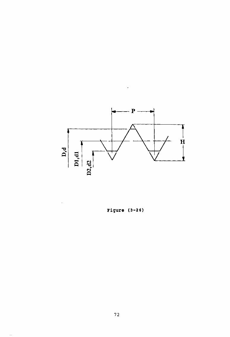
Figur« (3-26)
72

th e f o l lo w in g formula and ro u n d ed ,in th e t a b l e s , t o th e
t h i r d dec im al p la c e :
D, = D - 2 X 3 H/8 ■ D - 0.6495 Pda = d - 2 x 3 H/8 « d - 0.6495 pDA = D - 2 X 5 H/8 * D - 1.0825 Pdx = d - 2 x 5 H/8 = d - 1.0825 p
D im ensions o f th read form e lem en ts [5 3 ] , are :
H = x/TTi P = 0.866 025 404 p5 H/8 = 0.541 265 877 p3 H/8 = 0.324 759 526 pH/4 = 0.216 506 351 pH/8 = 0.108 253 175 p
3-6-3- Tolerance zone and class of f i t .
A to le r a n c e zone must be s p e c i f i e d b o th in
m agnitude and p o s i t i o n in r e l a t i o n t o th e b a s i c s i z e o f
th e f i t o f which i t i s a p a r t . The n atu re o f a f i t i s
dependent on both th e m agnitudes o f th e t o l e r a n c e s and
th e p o s i t i o n s o f th e t o le r a n c e zone fo r th e two member.
The p o s i t i o n o f a t o le r a n c e zone i s d e f in e d by th e
d i s t a n c e between th e b a s ic s i z e and th e n e a r e s t end o f
th e t o le r a n c e z o n e .
T h is d i s t a n c e i s known as th e " fundamental d e v ia t io n ".
In the ISO m etr ic screw th rea d system fundamental
d e v i a t io n s are d e s ig n a te d by l e t t e r s . C a p it a l s fo r
i n t e r n a l th read s and sm all l e t t e r s fo r e x te r n a l th r e a d s .
The m agnitudes o f t o le r a n c e zones are d e s ig n a te d by
t o l e r a n c e grades ( f i g u r e s ) .
73
A com bination o f a t o le r a n c e grade ( f ig u r e ) and a
fundamental d e v ia t io n ( l e t t e r ) forms a t o l e r a n c e c l a s s
d e s ig n a t io n , e . g 6g:
In BS 3643 " c l a s s o f f i t " i n d i c a t e s th e d eg ree o f f i t
between e x te r n a l (b o l t ) th r e a d s and i n t e r n a l (nu t)
t h r e a d s .
ISO d e f i n i t i o n s d e s ig n a te t h i s c o n d i t io n as t o l e r a n c e
q u a l i t y , but to m a in ta in co n fo rm ity w ith B r i t i s h p r a c t i c e
th e d e s ig n a t io n ■ c l a s s o f f i t • i s p r e fe r r e d . Thus, *
f i n e to le r a n c e q u a l i t y " conforms t o th e " c l o s e " c l a s s
o f f i t and "coarse t o le r a n c e q u a l i t y " conforms to th e ■
f r e e " c l a s s o f f i t . The " medium ■ d e s ig n a t io n i s common
to both m ethods.
The com plete ISO m e tr ic screw th r e a d t o l e r a n c in g sy s tem
p r o v id e s many com b inations o f t o l e r a n c e grade and
fundamental d e v ia t io n s to c a t e r f o r most a p p l i c a t i o n ;
t a b le (3-2) g i v e s , c l a s s e s o f f i t f o r ISO m e tr ic screw
th rea d s [52] .
A lso f ig u r e (3 -27 ) i l l u s t r a t e s t o l e r a n c e zones fo r t h e
c l o s e f i t (5H/4h) . From th e t o l e r a n c e zones shown in
f ig u r e (3-27) i t f o l lo w s th a t t h r e e d i f f e r e n t ty p e s o f
erro r are a llo w ed :
( a ) - E r r o r o f t h e f l a n k a n g l e .
(b) - E r r o r o f p i t c h o v e r t h e l e n g t h o f f i t t i n g .
( c ) - E rr o r o f e f f e c t i v e d i a m e t e r [ 9 ] .
3 - 6 - 4 - A p p l i c a t i o n o f f i t .
* Medium f i t ", (6H /6g) . The " medium ■ c l a s s o f
74
f i t i s a p p ro p r ia te fo r most g e n e r a l e n g in e e r in g p u r p o s e s .
The minimum c le a r a n c e a s s o c i a t e d w ith th e f i t a s s o c i a t e d
in f r e e assem b ly , and t h i s m in im izes g a l l i n g and s i z i n g
in h igh speed a ssem b ly .
■ c l o s e f i t ", (5 H /4 h ) . The ■ c l o s e " c l a s s o f i s a p p l i e d
t o threads r e q u ir in g a c l o s e r f i t than th a t n o r m a lly
o b ta in ed w ith th e " medium " c l a s s o f f i t and f i t and
sh ou ld o n ly be when c l o s e a ccu racy o f th rea d form and
p i t c h i s p a r t i c u l a r l y r e q u ir e d .
C o n s is te n t p r o d u ct io n o f th r ea d s o f t h i s f i t demands th e
u se o f h igh q u a l i t y p ro d u ct io n equipment and p a r t i c u l a r l y
through in s p e c t io n .
■ f r e e f i t ", (7H/8g) , th e * f r e e " c l o s e o f f i t i s
p r im a r i ly in ten d ed fo r a p p l i c a t io n s in which q u ick and
e a sy assem bly i s needed even when th e th rea d s have become
d i r t y and /or s l i g h t l y damaged.
F ig u re (3-28) shows th e r e l a t i o n s h i p between t o l e r a n c e
zones and c l a s s e s o f f i t [5 2 ] .
3-6-5- D e s ig n a t io n .
The com plete d e s ig n a t io n fo r a screw th r e a d
com p rises a d e s ig n a t io n fo r th e th rea d system and s i z e ,
and a d e s ig n a t io n fo r th e th read t o l e r a n c e c l a s s .
A screw thread d e s ig n a t e s by th e l e t t e r M f o l lo w e d by th e
v a lu e s o f nominal d iam eter and o f th e p i t c h , e x p r e s s e d in
m il l im e t r e s and se p a r a ted by th e s ig n x . For exam ple:
M6 x 0 .7 5
The ab sen ce o f th e i n d ic a t io n o f p i t c h means t h a t a
75
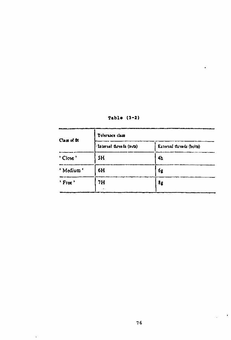
Tabi« (3-2)
CU ss of ftlToUrux* d u i
■ Internai thrrsdj (ovrti) LitenuJ tiLreaò (bolts)
* C!o*e ’ 5H 4b
• Medium ’ 6H 6«
* F r « ’ 7H H
76
«

VPPER LIMIT NVT
Figur« (3-27) Tolerance sones for close
fit (5H/4h)
77
v»c ddi

Close ftt
Nuts
Bolts
Designation 5M /4h

Med turn fit
Nuts
Free fit
Nuts
7 H
Minimum clearance (fundamental deviation) 1 ----------r
6 9
Bolts B o lts
6H/6g 7H /B g
8asicpitchdiameter
0esi9n«U ofl
Figure (3-28)
c o a r se p i t c h i s s p e c i f i e d . For example M6 th e t o l e r a n c e
c l a s s d e s ig n a t io n com p rises c l a s s d e s ig n a t io n fo r th e
p i t c h d iam eter t o le r a n c e fo l lo w e d by a c l a s s d e s i g n a t i o n
fo r th e c r e s t d iam eter t o l e r a n c e . Each c l a s s d e s i g n a t i o n
c o n s i s t s o f :
{ ! ) - A f i g u r e i n d i c a t i n g th e to le r a n c e g r a d e .
( 2 ) - A l e t t e r i n d i c a t i n g th e t o l e r a n c e p o s i t i o n ,
C a p ita l fo r n u ts , sm a ll fo r b o l t s .
I f th e two c l a s s d e s ig n a t io n s fo r a th read a r e th e same
i t i s not n e c e s s a r y t o r e p e a t th e symbols , [ 5 3 ] .
3-7 Inspection of screw thread.The in s p e c t io n o f screw th read s may be by g a u g in g
or m easuring .
3 - 7 - 1 Inspection b y gauging.
BS 919 " screw gauge l i m i t s and t o l e r a n c e s ",
p a r t th r e e "Gauges fo r ISO m etr ic screw th r e a d s ■
c o n ta in s th e recommended gau g in g sy stem f o r c h e c k in g
th r ea d s o f nominal d iam eter 1mm and la r g e r w h ich have
been accordan ce w ith BS 3 643 " ISO m e tr ic screw th r e a d s ■
p r o v i s io n i s made fo r th e f o l lo w in g ty p e s o f g a u g es:
(a)- Screw ga u g es .
(b)- p l a i n gauges ( fo r th e c r e s t d ia m e t e r s ) .
(c)- S e t t in g p lu g s , in bo th s i n g l e and d ou b le l e n g t h .
(d)- Check p lu g s .
(e)- Wear check p lu g s .
In fo rm a tio n i s g iv e n about th e fu n c t io n and m ethods o f
79
u se o f the v a r io u s ty p e s o f gauges and a recommended
procedure i s g iv e n fo r th e s e t t le m e n t o f d i s p u t e s w h ich
may a r i s e when b o a r d l in e p r o d u cts are in s p e c t e d .
3 - 7 - 2 Inspection b y m e a s u r e m e n t .
Measurement o f a screw th r ea d s can be v e ry com plex;
t h e r e b e in g a number o f e le m en ts to be measured, some o f
which are i n t e r r e l a t e d . Of th e e le m e n ts , th e f o l lo w in g
w i l l norm ally be measured:
( a ) - Major D iam eter .
(b ) - Minor D ia m eter .
(C) - Form, p a r t i c u l a r l y f l a n k a n g l e s .
( d ) - P i t c h .
( e ) - P i t c h d i a m e t e r .
th e measurement o f th e f la n k a n g le s i s th e most im p ortan t
measurement o f th read form w hich, on v ery la r g e screw
th r e a d s , may be made by c o n t a c t methods [ 5 4 ] .
F u l l in fo r m a tio n on th e m easuring o f screw th rea d s w i l l
be found in th e NPL b o o k le t . N otes on A p p lied s c i e n c e ,
N 0.1: Gauging and m easuring screw th read s [4 4 ] .
A lso , In form ation concern autom ated th read m easurem ent,
u s in g d i f f e r e n t methods and te c h n iq u e s , fo r th e l a s t
decad e , can be found in c h a p te r two.
80

CHAPTER FOUR
4-DEVELOPMENT OF THE MEASURING
R IG .
The o ld e s t o f th e p h y s i c a l s c i e n c e s i s th e s tu d y o f t h e
motion o f th e o b j e c t s .
K inem atics: I s th a t p a r t o f mechanics [5 5 ] , which d e a l
w ith m otions o f b o d ie s w ith ou t regard t o t h e f o r c e
r e s p o n s ib le o f th e m otions .
D isp lacem ent: I s th e v e c t o r q u a n t ity a r i s e s in t h e s tu d y
o f k in em a tic s , [5 6 ] , which may be d e f in e d as a change o f
p o s i t i o n o f a p a r t i c l e [ 5 5 ] .
4-1 Definitions.
2 - ACCURACY OR CORRECTNESS :
This may be d e f in e d as th e amount o f c o r r e c t io n which
must be made to th e in stru m en t rea d in gs in r e s p e c t o f th e
v a lu e s o f th e q u a n t i t i e s b e in g measured, [5 4 ] , a l s o i t
may be d e f in e d as co n fo rm ity w ith or n ea rn ess t o th e t r u e
v a lu e o f th e q u a n t i ty b e in g measured [5 7 ] .
2- POINT OF ACCURACY :
Here the accuracy o f an instrum ent i s s t a t e d fo r o n ly
81

one or more points in its range [57] .
3 - PERCENTAGE OF TRUE VALUE :
If th e accuracy o f an instrum ent i s e x p r e sse d in t h i s
way, th en th e error i s c a lc u la t e d th u s:
Error ={ ( M, - Tt ) / T„ } x %100 (4-1) .
The p e r ce n ta g e erro r s t a t e d i s th e maximum fo r any
p o in t in range o f the in stru m en t, [ 5 7 ] .
4 - PERCENTAGE OF FULL-SCALE DEFLECTION PERCENTAGE (f.s.d)
Here th e erro r i s c a lc u la t e d on th e b a s i s o f th e
maximum v a lu e o f th e s c a l e , th u s [ 5 7 ] :
Error« { ( M* - Tv ) / M. > x 100% (4-2) .
5 - PERCISION OR REPEATABILITY :
T his i s th e r e p e a t a b i l i t y o f th e rea d in g taken o f th e
same v a lu e by th e same in stru m en t [ 5 7 ] .
6- SENSITIVITY AND RANGE :
T his may be d e f in e d as th e r a te o f d isp la cem en t o f th e
i n d ic a t in g d e v ic e o f an in s tru m en t, w ith r e s p e c t t o th e
measured q u a n t i t y . See f ig u r e ( 4 - 1 ) , [ 5 4 ] .

The s e n s i t i v i t y i s taken t o mean th e r e l a t i o n betw een th e
input s ig n a l t o an instrum ent or a part o f an instru m en t
system and th e outp ut, i . e .
Sen * (C.O.S )/ (C.I.S ) (4-3).The s e n s i t i v i t y w i l l t h e r e f o r e be a c o n s ta n t in a l i n e a r
instrum ent or e lem en t.
7 - ENVIRONMENT ;
The p a r t i c a l c o n d it io n in which an instrum ent has t o
o p erate may a f f e c t , i t s accu racy , p r e c i s i o n , and
r e l i a b i l i t y .
S - LINEARITY :
Is d e f in e d as th e a b i l i t y to
c h a r a c t e r i s t i c a l l y , and t h i s
e q u a t io n :
Y = m x + c
9~ RELIABILITY :
The r e l i a b i l i t y o f a system i s as d e f in e d as th e
p r o b a b i l i t y th a t i t w i l l perform i t a s s ig n e d f u n c t io n s
fo r a s p e c i f i c p e r io d o f tim e under g iv en c o n d i t io n .
reproduce th e in p u t
can be e x p r e sse d by th e
( 4 - 4 ) .
83

F ig u re ( « - ! )
84

10- MAINTAINABILITY
The m a in t a in a b i l i t y o f a system i s th e p r o b a b i l i t y
t h a t in th e ev en t o f f a i l u r e o f th e system , m aintenance
a c t io n under g iv en c o n d it io n s w i l l r e s t o r e th e system
w ith in a s p e c i f i e d t im e .
*
1 1 - CALIBRATION :
I t i s an e s s e n t i a l part o f i n d u s t r i a l measurement and
c o n t r o l . I t can be d e f in e d as th e com parison o f s p e c i f i c
v a lu e s o f th e input and output o f an instrum ent w ith a
c o rresp o n d in g r e fe r e n c e standard [5 4 ] .
1 2 - STYLUS :
The s t y l u s i s th a t part o f th e m easuring system which
makes c o n ta c t w ith th e component c a u s in g th e probe t o
produce a t r i g g e r s i g n a l . The ty p e and s i z e o f s t y l u s
u sed i s d i c t a t e d by th e f e a tu r e t o be in s p e c t e d . In a l l
c a s e s , maximum r i g i d i t y and s p h e r i c i t y o f th e s t y l u s are
v i t a l [ 5 8 ] .
4 -2 P r i n c i p l e s o f d e s ig n
4-2-1 Kinematics principles
M easuring instrum ents and m ach ines, in c o r p o r a te , in
t h e i r im portant f e a t u r e s , p r i n c i p l e s , which are b ased on
k in e m a t ic s . I t w i l l be seen t h a t , in g e n e r a l th e m otions
85
, which must be c o n s id e r e d in th e d e s ig n o f a m easuring
im achines are th o s e o f s t r a i g h t l i n e and r o ta r y m otion ,
iD e s ig n e x p e r ie n c e over many years has shown t h a tii: k in em a tic p r i n c i p l e s must be c l o s e l y fo l lo w e d , in order
| t h a t machines and in stru m en ts should p o s s e s s th e
f o l lo w in g c h a r a c t e r i s t i c s :I
( a ) - A h i g h \ l e g r e e o f s e n s i t i v i t y .i (b)- A h igh degree o f accu racy .i
■ ( c ) - Freedom from v a r ia n c e .
; <d)- minimum i n e r t i a in th e moving p a r ts o f th e
| in d ic a t in g mechanism.
i ^| A l l in stru m en ts which depend w h olly or in p a r t on a
' l in k a g e or o th er m echanical system or on th e d isp la cem en ti' o f a f l u i d , fo r t h e i r o p e r a tio n are su b je c t t o th ei
d isa d v a n ta g e o f i n e r t i a .I, I n e r t i a produces a c o n d it io n r e fe r r e d to as p a s s i v i t y orIS l u g g i s h n e s s . I t may be determ ined fo r any g iv e n
instrum ent by n o t in g th e s m a l le s t range in th e measuredi
!q u a n t i ty which produces any change in th e instrum entiIr e a d in g . P a s s i v i t y i s c l o s e l y a s s o c ia t e d w ith
s e n s i t i v i t y : p a s s i v i t y may o n ly show i t s e l f as a change
| in th e s e n s i t i v i t y o f an instrum ent a t a p a r t i c u la r p o in t
i in i t s s c a l e read in g th e m easuring machine in a d d it io n t oIi in s tr u m e n ts , a l s o p o s s e s s th e fo r e g o in g c h a r a c t e r i s t i c s ,i
and th a t in each c a se th e y may be reduced t o a c c e p ta b leri l i m i t s by th e a p p l ic a t io n o f k in em atic p r i n c i p l e s . In
| f a c t on ly by s t r i c t observance o f them can th e f u n c t io n a l
I
86

requirem ents o f a d e s ig n be s a t i s f i e d .
Commonly, in m easuring in s tru m en ts and m achines, i t i s
n e c e ssa r y t o a l lo w one d egree o f freedom o f a member,
which req u ire f i v e c o n s t r a i n t s , or t o co m p le te ly c o n s ta n t
a member, th u s c o n s t i t u t i n g a f i x t u r e .
Only by th e a p p l i c a t io n o f k in em a tic p r i n c i p l e s can th e
d e s ig n o f an instrum ent or machine be such th a t i t s
accuracy in o p e r a t io n does r e s t e n t i r e l y on i t s accuracy
o f m anufacture.
Not on ly do k in em atic p r i n c i p l e s a l lo w s s i m p l i c i t y o f
m anufacture, but th ey p ro v id e fo r adjustm ent a ti
instrum ent assem bly and t e s t i n g s t a g e , so th a t c o m p le te ly
, s a t i s f a c t o r y o p e r a t in g c h a r a c t e r i s t i c s may be a c h iev e d .
4-2-2 Basic characteristic of measuring devices .
i
The fu n c t io n o f a m easuring d e v ic e i s t o se n se or
d e t e c t a param eter en countered in an i n d u s t r i a l p r o c e ssi'or in s c i e n t i f i c r e se a r c h , such as a p r e s s u r e ,
tem p erature , f lo w , m otion, r e s i s t a n c e , v o l t a g e , cu rren t
’and power.
; The m easuring d e v ic e must be ca p a b le o f f a i t h f u l l y and
a c c u r a te ly d e t e c t i n g any changes t h a t occur in th e
measured param eter. For c o n tr o l p u rp ose , th e measuring
instrum ent e i t h e r g e n e r a te s a warning s ig n a l to in d ic a t ejth e need fo r a manual change or a c t i v a t e s a c o n tr o l
d e v ic e a u t o m a t ic a l ly . For o b ta in in g optimum perform ance,
a number o f b a s ic c h a r a c t e r i s t i c s are to be c o n s id e r e d .
These c h a r a c t e r i s t i c s are as f o l lo w s : Accuracy,
87

1 precision, error, linearity, hysteresis, resolution and ; scale readability, threshold, reliability andiI maintainability, span, and dynamic accuracy.] The accu racy o f a com plete system i s dependent upon th e
i in d iv id u a l a c c u r a c ie s o f th e primary s e n s in g e le m en t ,
, secondary e le m en t , and th e m a n ip u la t in g d e v i c e s . Each
j u n i t c o n t r ib u t e s t o th e accuracy w ith s e p a r a te l i m i t si| s p e c i f i e d . I f ( + / - a ^ , ( + / -a 2) and ( + / - a 3) are th e|i accu racy l i m i t s o f a t y p i c a l system , and A i s th e o v e r a l l
j accu ra cy , th e lo w e s t l i m i t o f accu racy can be e x p r e s s e d
1 a s :
A= +/- (ax + a2 + a3) (4-5) .i
i>and th e ro o t mean square i s o f t e n s p e c i f i e d , s i n c e i t i s
jnot p robab le t h a t a l l th e u n i t s o f th e system w i l l have
¡the g r e a t e s t s t a t i c e r r o r a t th e same p o in t and a t th eI;same t im e .i
I In a c tu a l measurement th e e f f e c t o f th e d i f f e r e n t e r r o r sjon th e tr a n sd u c e r b eh av iou r sh ou ld be c l e a r l y known.
jThe knowledge o f t h e s e in d iv id u a l e r r o r s , can be o f t e n
used to c o r r e c t th e f i n a l data and th e re b y in c r e a s e th eio v e r a l l accu racy o f th e measurement.iThe e r r o r o b served when th e in stru m en t i s under th e
r e fe r e n c e c o n d i t io n i s termed as th e i n t r i n s i c e r r o r . The
jabsolute e r r o r i s th e d i f f e r e n c e o b ta in e d by s u b t r a c t in g
th e t r u e v a lu e o f a q u a n t i ty from t h e ob served v a lu e . The
r e l a t i v e e r r o r i s th e r a t i o o f th e a b s o lu t e e r r o r to th e
t r u e v a lu e .
In c e r t a i n c a s e s , i t may be n e c e s s a r y t o e x p r e s s t h i s as
88

relative linearity error k which can be written as:
k - ( k, - k» ) / k. (4-6)
The s t a t i s t i c a l e r r o r s in a measurement can be
c o n s id e r e d in term s o f th e s t a t i s t i c a l mean and th e
stan dard d e v i a t io n . I f x2, x2, . . . . x 2 r e p r e se n t a s e t o f
measured v a lu e s o f a q u a n t i ty , th e s t a t i s t i c a l mean ~x o f
t h e s e r ea d in g s i s g iv en by:
The stan dard d e v ia t io n , i n d i c a t i n g th e d egree o f
d i s p e r s io n o f read in g s about a mean v a lu e , can be
e x p r e sse d a s :
I f th e measurement system i s s u b je c te d to r a p id ly v a r y in g
' in p u ts , th e r e l a t i o n between th e in p u t and output becomes
d i f f e r e n t from t h a t o f th e s t a t i c or q u a s i s t a t i c c a s e .
The dynamic resp on se o f th e system can be e x p r e s s e d by
means o f a d i f f e r e n t i a l e q u a t io n . I f t h i s i s a l in e a r
d i f f e r e n t i a l e q u a t io n , th e system i s d y n a m ica lly l i n e a r .
The b a s i c dynamic c h a r a c t e r i s t i c s depend on th e order o f
d i f f e r e n t i a l e q u a t io n o f th e system [5 9 ] .
iIi4-2-3 Intelligent instrumentation:
n
(4-7).i = l
i = l
89

Intelligent instrument is a term, which has come to, mean: the use of measurement system to evaluate a1 physical variable employing usually a digital computer to perform all (or nearly all ) the signal/ information
i■ processing.i It is one where after a measurement has been made of a 1 variable some further processing (analogue or digital) isicarried out to refine the data, for presentation to an I observer or other computers.Intelligent instrumentation involves the development of systems to process information and signals. Thus the .concepts of systems engineering can be applied. The signal is connected to a processing system which would 'probably include some or all of the following elements: sampler, analogue to digital converter, interface to ^digital computer, software routine and software output driver.i
, To achieve the good design of system in intelligent instrumentation a style of engineering is adopted which utilities computer systems, control systems and digital electronics in various mixes, [60].
4-3 Design and development of an automatic inspection system.
| In general, kinematics principles, basiccharacteristics of measuring device, and the concepts of an intelligent instrumentation are adopted with other considerations to design and arrange the different
90

elements of our automatic measuring system.Lever, clamping and rotating, and sliding mechanisms, which are driven and controlled by a personal computer,are refered to as the mechanical design.
%W hile, motors and t h e l in e a r v a r ia b le d i f f e r e n t i a l
transform er (LVDT), where t h e i r s i g n a l s are i n t e r f a c e d
and p ro cessed u s in g a s p e c i a l arrangem ents, are r e f e r e d
t o as the e l e c t r i c d e s ig n .
F igure (4 -2 ) , shows th e main e lem en ts o f th e adop ted
d e s ig n , which are in c lu d e d under th e fo l lo w in g :
(1)- Mechanical design.(2)- Electronic design.
Also special software was prepared to drive, control and process the different Input/Output signals.
4-3-1 Mechanical design.
A certain information and data, relating designing factors and other considerations, such as frictional force and moment of inertia were considered and calculated to find out the different characteristic specification of our mechanical elements.Frictional force opposes movement regardless of direction, where, moment of inertia is an indication of resistance to change in speed. Thus, shapes and weights of the different moving elements were carefully calculated, because, moment of inertia depends on shape

LVDT
PROTECTION BOX
MICRO-8WITCHMMOTOR (1) Mechanical Design
figure (4-2)

as well as weight, also low frictional forces have been achieved by using linear ball bushings and ball screw The following mechanisms represent our mechanical design:
(1)- Lever mechanism
(2)- Clamping and rotating mechanism
(3)- Sliding mechanism.
4-3-1-1 Lever mechanism»
The lever, is one of two simple mechanical magnifying elements Figure (4-3), shows, that the mechanism consists of a stylus which represent the first sensing element m our measuring system Different types of stylus may be fixed on the specified hole on one side of the stylus arm, while, an electrical sensing element makes the required contact at a specified point on the other side of the stylus armPivot holds the stylus arm to the lever body which may be adjusted to any height on the shaft using a special bolt The shaft is fixed tightly to the lever base The stylus arm has one degree of freedom (pivot on point)Pivot and stylus tip control the sensitivity of this
mechanism, therefore a suitable tolerances were adopted to fit the required accuracyIf a stylus is dragged along the surface, its motion traces out the profile of the surface thus, required rotating on pivot point is generated by the object under test causing a certain displacement to the stylus The
93

LITO MECHANISM.x>......... STYLOS
n u l o s HOLT
..........................u m ARM
.
......... LIVE* BoOY
.........<ITD*) BOLT
......... ADJUSTING BOLT
......... HAFT
......... BASI

difference between two heights is amplified by the lever which converted on the other side into electrical signal The stylus arm and the lever body are made of aluminum H30, pivot material is phosphor bronze The stylus used for the simulation tests was made of silver steel The stylus arm, lever body, pivot and the previous stylus were manufactured at the workshop of the school of mechanical and manufacturing engineering While the stylus, SP75, SP36R and SP20R, were purchased from (Inspection Equipment Co.Ltd unit 37, Western Parkway Business Centre, Ballymount Road, Dublin 12)The shaft, bolts and lever base were ready at the workshop
4-3-1-2 Clamping and rotating mechanism
The Clamping and rotating mechanism provides the object under test the required support, and the desired form of motion It consists of four separate sets, which are fixed to a solid baseF igu re ( 4 - 4 ) , i l l u s t r a t e s t h e s e s e t s , which are as
fo l lo w s
(1)- Support jaw
(2)- Vee block
(3)- Movable jaw
(4)- Motor set and base
(1)- Support jaw
95

I
I
Figure (4-4)
t---------

/
This set provides the object under test, the required side supporting during various steps of the operational cycleIt consists of a base made of Aluminum H30, and has one degree of freedom which may be used for calibration task before starting the cycle Thrust bearings , shaft , and changeable jaw with special bolt.The jaw has one degree of freedom and its martial is silver steel, like the shaft which also has one degree of freedom Figure (4-5)The base, jaw and shaft were manufactured at the workshop of the school, while the thrust bearings were purchased from, (FAG Ireland limited, Greenhill industrial Eastate, Walkinstown, Dublin 12)
(2)- Vee block
In order to increase the flexbility of the system , vee block were designed to fit different sizes of the cylindrical objectsFigure (4-6), illustrates the different parts, which are, the vee block body, cylindrical guidance, holding bolt, and adjusting elementThe fine thread which represents the adjusting element in our design, controls the vertical position of the object under test to the correct height, it has a very small increment, which generates as soon as rotating it.iTherefore, micrometer can be replaced instead of it , toiachieve further degree of accuracy, and to make the
97

c a l i b r a t io n ta s k , more e a sy , qu ick , and p e r f e c t
S tr o n g ly , we recommend, th a t c a l i b r a t io n sh ou ld be
performed once fo r each type o f in s p e c t io n , a l s o , h o ld in g
b o l t shou ld not be a llo w ed t o move a f t e r c a l i b r a t i o n ,
th u s e r r o r s due to t h i s c a l i b r a t io n w i l l not tak e p la c e
The f i n e thread and c y l i n d r i c a l gu idance are made o f
s i l v e r s t e e l , and The vee b lock and h o ld in g b o l t are made
o f Aluminum H30. A l l p a r ts were manufactured in th e
workshop o f th e sc h o o l
(3)- Movable jaw
The s e t p r o v id e s th e o b je c t under t e s t w ith th e
th r e e fo l lo w in g m otions
(a)- Clamping- the object
(b)- Provide the object the rotating motion to accomplish the helix inspection step
(c)- Releasing the object at the end of the test
A s p e c i a l d e s ig n , has a sim ple f e a tu r e adopted in order
to a c h iev e the p r e v io u s m otions
The d e s ig n c o n s i s t s o f , a clam ping jaw which has two
d e g r ee s o f freedom, f ix e d c y l in d e r has an in t e r n a l
gu id an ce , cover , th r u s t b e a r in g s , c l i p - n n g s , le a d screw ,
sp r in g and housing body se e f ig u r e (4-7)
The Clamping jaw, and th e lea d screw are made o f s i l v e r
s t e e l , Cover, f i x e d c y l in d e r , and h ou sin g body are made
o f Aluminum H30
98

(10) (12) (13) (14)
SUPPORT JAW(10 )........ JAW
\ (11 )........ SHAFT(12 )......... BOLT
Figure (4-5) (13).........BEARING(14)........ BODY
99

F ig u r e (4 -6 )
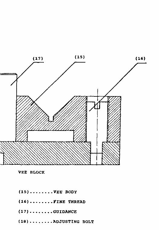
VEE BLOCK
(15 )....... VEE BODY(16 )....... FINE THREAD(17 )....... GUIDANCE(18 )....... ADJUSTING BOLT

MOVABLE JAW(19 )........ MOVABLE JAW(20 ).........CYLINDER(21 ).........COVER(22 ).........SPRING(23 )....... LEAD SCREW(24 )....... CLAP RING
V(25 )........BEARINGS(2 6)...... HOUSING BODY
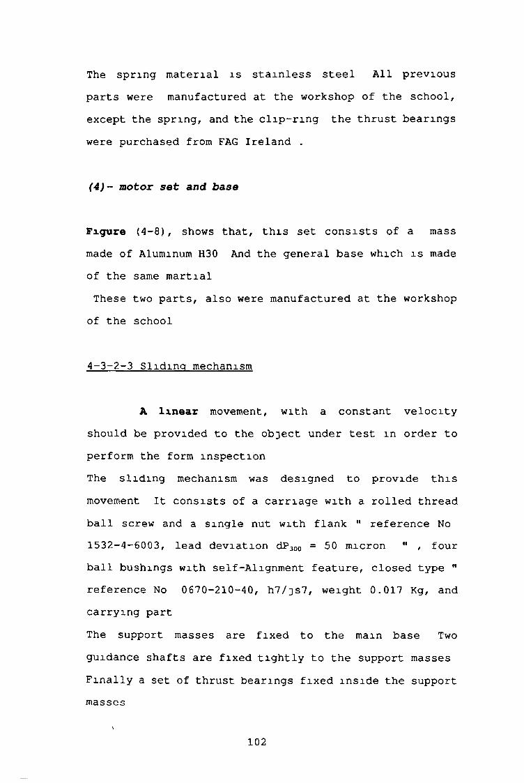
The sp r in g m a te r ia l i s s t a i n l e s s s t e e l A l l p r e v io u s
p a r ts were manufactured a t th e workshop o f th e s c h o o l ,
ex cep t th e sp r in g , and th e c l i p - r i n g th e th r u s t b e a r in g s
were purchased from FAG Ir e la n d .
(4)- motor set and base
F igu re ( 4 -8 ) , shows th a t , t h i s s e t c o n s i s t s o f a mass
made o f Aluminum H30 And th e g e n e r a l b ase which i s made
o f th e same m a r t ia l
These two p a r t s , a l s o were m anufactured a t th e workshop
o f th e sch o o l
4 - 3 -2 - 3 S l id in g mechanism
A l i n e a r movement, w ith a c o n s ta n t v e l o c i t y
sh ou ld be p ro v id ed to th e o b je c t under t e s t in order to
perform th e form in s p e c t io n
The s l i d i n g mechanism was d e s ig n e d t o p ro v id e t h i s
movement I t c o n s i s t s o f a c a r r ia g e w ith a r o l l e d th read
b a l l screw and a s i n g l e nut w ith f la n k " r e fe r e n c e No
15 32-4 -6003 , le a d d e v ia t io n dP300 = 50 micron " , four
b a l l bu sh ings w ith se l f -A lig n m e n t f e a t u r e , c lo s e d ty p e "
r e fe r e n c e No 06 70 -210-40 , h 7 / j s 7 , w e igh t 0 .017 Kg, and
c a r r y in g part
The support m asses are f i x e d t o th e main b a se Two
guidance s h a f t s are f ix e d t i g h t l y to th e support m asses
F in a l l y a s e t o f th r u s t b e a r in g s f i x e d i n s id e th e support
m asses
102

MOTOR SE T
(27 ).......COUPLING(28 )...... MASS(29 )..... MOTOR

(28)
Figure (4-8)

The r o l l e d th read b a l l screw i s jo in e d to th e d r iv in g
motor through c o u p lin g F igure (4-9) , i l l u s t r a t e s t h e s e
p a r ts
The d e s ig n has one d egree o f freedom fo r th e movable
p a r t s , s l i d i n g fo r th e c a r r ia g e , and r o t a t in g fo r th e
r o l l e d th read b a l l screw and th e th r u s t b e a r in g s
The c a r r ia g e , c a r r y in g p a r t , support masses and th e main
base are made o f Aluminum H30 While c o u p lin g i s made o f
s i l v e r s t e e l These p a r t s were manufactured a t th e
workshop o f th e sc h o o l
th r u s t b e a r in g s were purchased from FAG Ir e la n d
The r o l l e d th read b a l l screw , s i n g l e nut w ith f la n k ,
guidance s h a f t s and th e b a l l b u sh in g s were purchased from
RHP b e a r in g s
I t can be n o t ic e d th a t most o f th e p a r t s were made o f a
l i g h t w eight m a te r ia l in order to reduce th e moment o f
i n e r t i a
F in a l l y , th e f r i c t i o n a l f o r c e s were ig n o red , b ecau se o f
u s in g th e b a l l b u sh ing , the, r o l l e d th read b a l l screw and
s i n g l e nut system
4 -3 -2 E le c t r o n ic d e s ig n
Two im portant t a s k s are req u ire d o f our e l e c t r o n i c
e le m e n ts , th o se are-
(1)- Driving the mechanical parts(2)- Translate the stylus movements into a usable
output
105

(30)
Figure (4-9) SLIDING MECHANISM\
(30 ).....U MASS(31 )....CARRIAGE(3 2 ) ..........MASS
(33 )....GUIDANCE SHAFT(34 )....LEAD SCREW
(35).... BEARINGS(3 6)....LEAD SCREW(37 ).... COUPLING(38 ).... MOTOR SHAFT(39) .....GENERAL BASE
106

4-3-2-1 Motors
<1>- The basic DC motor operation
Direct-current m otors (DC) are one o f th e most
w id e ly used in c o n tr o l sy s tem s and th e y have many
a p p l i c a t io n s in computer p e r ip h e r a l equipm ent.
The DC motor i s b a s i c a l l y a torq u e tra n sd u c er t h a t
c o n v e r ts e l e c t r i c a l energy i n t o m echan ica l energy The
to rq u e develop ed on th e motor s h a f t i s d i r e c t l y
p r o p o r t io n a l to th e f i e l d f l u x and th e armature cu rren t
The r e la t io n s h ip between th e d e v e lo p e d to rq u e , f l u x , and
cu r re n t i s .
a l s o , th e r e l a t io n s h ip between t h e back (emf) and s h a f t
v e l o c i t y i s
E quation (4-9) and (4-10) from th e b a s i c o f DC motor
o p e r a t io n , fo r fu r th e r d e t a i l s e e r e f , [58]
(2)- Factors of selecting- motor
Two se p a r a te f ig u r e s are needed when s e l e c t i n g a
DC motor
(a)- A peak to rq u e , b e in g th e sum o f a c c e le r a t i o n
T. = K - 4> I. (4-9)
(4-10)
J
107

<b)- A co n tin u o u s torque which i s th e f r i c t i o n
component on ly
th e torque produced by th e motor i s g iv e n by :
T * k*. I (4 -1 1 )
The ch o ice o f motor and d r iv e must s a t i s f y t h e f o l lo w in g
c o n d i t io n s .
1 - The product o f kt and con tin u ou s d r iv e c u r r e n t must
g iv e the r e q u ire d peak torque
2- The product o f k t and con tin u ou s d r iv e c u r r e n t must
produce s u f f i c i e n t con tin u ou s to r q u e .
3 - The maximum a l lo w a b le motor cu rren t must be g r e a t e r
than the peak d r iv e cu rren t
4- At maximum speed and peak c u r r e n t , th e v o l t a g e
developed a c r o s s th e motor must be l e s s than 80% o f
th e d e v ic e su pp ly v o l t a g e .
The v o lta g e a c r o s s th e motor i s g iv en by [59]
E - k* v + RI (4-12)
( 3 ) - Torque and inertia calculation
The moment o f i n e r t i a o f s tan d a rd m ech an ica l
components can u s u a l ly be c a lc u la t e d q u i t e e a s i l y u s in g
a few sim ple form ula These formula r e l a t e t o i n d iv id u a l
components or p a r t s o f a system , and g e n e r a l ly e a s i e r t o
u se than com p osite e x p r e s s io n s fo r an e n t i r e system which
can be ra th er d ou b tin g
The i n e r t i a o f any m echan ica l arrangement can be found by
c o n s id e r in g i t as a s e r i e s o f in d iv id u a l e le m e n ts ,
and frictional toques.
108

s t a r t i n g a t th e f i n a l load to be moved and working back
to th e motor Once a motor has been chosen We add i t s
own i n e r t i a to th e r e s t o f th e system
Most c y l i n d r i c a l components ( s h a f t , d i s c s , p u l le y s e t c )
w i l l be made o f s t e e l or aluminium, in which c a se th e
i n e r t i a can be c a lc u la t e d very q u ic k ly Use th e g e n e r a l
form ula fo r o th er m a te r ia ls For h o llo w c y l in d e r s ,
c a l c u l a t e th e i n e r t i a as th e d i f f e r e n c e o f two s o l i d
c y l i n d e r s .
For " m etr ic system"
For steel j = D4 L/1300 (4-13)
For aluminium j = D*L/3800 (4-14)
Appendix (A 4-1), g iv e s th e form ula which are used fo r
t h i s c a l c u l a t io n s
(4)- Technical specification of selected motors
A steel geared 11 medium duty 11 motor i s s e l e c t e d
t o d r iv e th e clam ping and r o t a t in g mechanism
This motor has th e t e c h n ic a l s p e c i f i c a t i o n g iv e n in
Appendix (A 4-2 ) , and bought from R a d io n ics , Herberton
road D ublin 12
While a heavy duty motor i s s e l e c t e d to d r iv e th e s l i d i n g
mechanism and i t bought from th e same company t h i s motor
has th e t e c h n i c a l s p e c i f i c a t i o n g iv en in th e Appendix
(A4-3)
109
4 - 3 - 2 - 2 L i n e a r V a r i a b l e D i f f e r e n t i a l Transformer(LVDT)
A b a s i c e l e c t r o n i c m easuring system i s shown in
f ig u r e (4-10) I t c o n s i s t s o f
( D - The tra n sd u cer (or s e n s o r ) , which c o n v e r ts th e
measurand in t o a u sa b le e l e c t r i c a l output
(2 ) “ The s ig n a l c o n d i t io n e r , which c o n v e r ts th e
tran sd u cer output in t o an e l e c t r i c a l q u a n t i ty
s u i t a b l e fo r proper o p e r a tio n th e d i s p la y d e v ic e
( 3 ) - The power su p p ly , which fe e d s th e req u ired
e l e c t r i c a l power t o th e s ig n a l c o n d i t io n e r ,
p ro v id es e x c i t a t i o n fo r a l l ex cep t " s e l f
g e n e r a t in g " ty p e s o f tr a n sd u c e r s , and may a l s o
fu r n ish e l e c t r i c power to c e r t a in ty p e s o f d i s p la y
d e v ic e s
( 4 ) - The d is p la y d e v ic e (or read o u t ) , which d i s p la y s
th e req u ired in fo rm a tio n about th e measurand [15]
An im portant d isp la cem en t tra n sd u cer e x t e n s i v e l y used
fo r many i n d u s t r i a l and m edica l a p p l i c a t io n s , th e l in e a rX
v a r ia b le d i f f e r e n t i a l tran sform er [1 3 ] , [15] U su a l ly
r e f e r r e d to LVDT or sometimes a d i f f e r e n t i a l tra n sfo rm er
(a)- The basic operation of the LVDT
This sen so r i s a tran sform er w ith a s i n g l e
primary w indings and two i d e n t i c a l secondary w indings
wound on a tu b u la r fe r r o -m a g n e t ic former The primary
w inding i s e n e r g is e d by an a c v o l ta g e o f am plitude Vs,
frequ en cy f s Hz, th e two se c o n d a r ie s are con n ec ted in
1 1 0
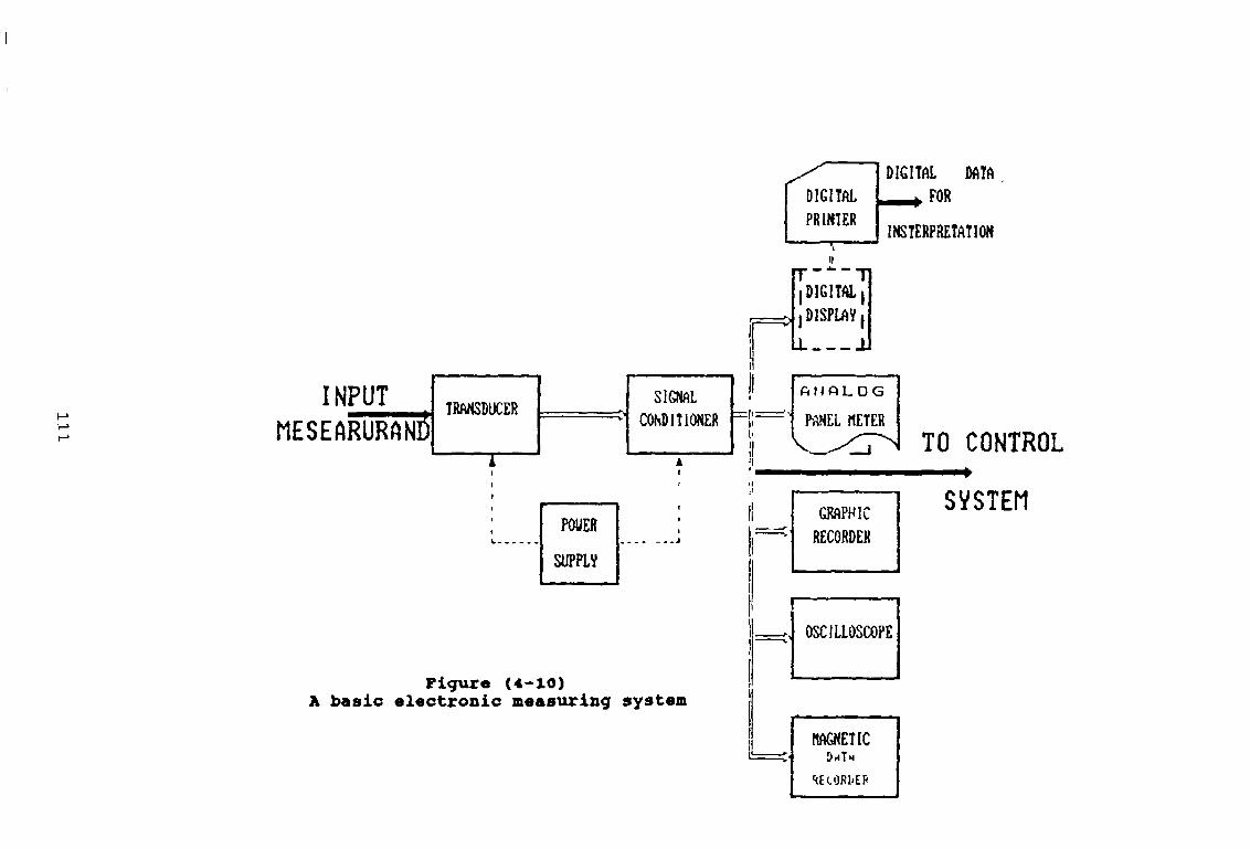
SIGNAL '' CONDITIONER
i à
POUERL----SUPPLY
INPUTMESEARÜRfitS
Figure (4-10)A basic electronic measuring system
DIGITALPRINTER
DIGITAL DATA t FOR
INTERPRETATION
DIGITALI DISPLAY|
lL J j
f i t l f l L O G
PftNEL METERTO CONTROL
MAGNETICImTh
SEtORI'Ef1
SVSTEM

s e r i e s o p p o s i t io n , so th a t th e output v o l ta g e
Vout X Sm (2 x 3 14 x f s t + 0)
i s th e d i f f e r e n c e ( Vx-V2 ) o f th e v o l t a g e induced m th e
s e c o n d a r ie s A ferrom agn etic core or p lu nger moves i n s id e
th e former, t h i s a l t e r s th e mutual in d u ctan ce between th e
primary and s e c o n d a r ie s .
' With th e core movement th e secondary v o l t a g e s are
i d e a l l y equal so th a t Vout + 0 . With th e core in th e
former, V 1 and V2 change w ith core p o s i t i o n x, c a u s in g
am plitude Vout and phase 0 t o change, th e r e l a t i o n s h i p s
between Vout, 0 and x are shown in f ig u r e (4-11) We se e
t h a t th e r e i s a n u l l p o in t c a t th e c e n tr e o f th e se n so r
(x =1/2 L ) where Vout = 0 ( i d e a l l y ) , here th e r e i s equal
c o u p lin g between th e primary and se c o n d a r ie s , so t h a t Vx
= V2 At th e p o in t s A and B equal spaced e i t h e r s id e o f
th e n u l l p o in t , Vout has th e same v a lu e VQ However, a t A
th e output v o l t a g e i s 180 out o f phase w ith th e primary
v o l t a g e i e 0 = 0°, (Vt > V2) N o n - l in e a r e f f e c t s occur a t
e i t h e r end (D and E) as th e core moves to th e edge o f th e
former [11]
(b) - Characteristics of the LVDT
C h a r a c t e r i s t ic s o f th e LVDT in c lu d e th e f o l lo w in g
(1 ) - R e so lu t io n i s e x c e l l e n t
( 2 ) - H y s te r e s i s i s very sm all
( 3 ) - Response and dynamic c h a r a c t e r i s t i c s are e x c e l l e n t
(4)- Temperature c h a r a c t e r i s t i c s are e x c e l l e n t
1 1 2

V* sin2 n/$f
"o 5 & O-Phase-sensitive demodulator +low past filter 0
“O
VqC
x - 0
Pigure <4-ii)Linear Variable Detferential
Trans former (L. V . D. T)
113

(5)- V ib ra t io n and env iron m en ta l s e n s i t i v i t y are good.
(6)- L in e a r i ty , m echanical o v e r lo a d c a p a b i l i t i e s , and
l i f e are e x c e l l e n t [1 3 ] .
(O- The major advantages of the LVDT.
The major advantages o f th e l in e a r v a r ia b le
d i f f e r e n t i a l tran sform er are as f o l lo w
(1)- There is no frictional contact between the core and the coil and therefore the LVDT has a longer lifethan a potentiometer
(2)- Infinite resolutionJ[62]
(d)- Technical specification of selected LVDT
Selected LVDT was o f ty p e o f GT x 2500, i t has th e
t e c h n i c a l s p e c i f i c a t i o n shown in th e Appendix (A4-4)
T his sen sor was purchased from R D P e l e c t r o n i c Ltd
Wolverhampton, England.
The com plete in fo rm a tio n are g iv e n by i t s c a ta lo g u e
This sen so r has an adequate range , r e s o l u t io n , and
a c c u r a te enough fo r th e measurement
4-4 Computer interfacing and signal processing
In our world v a r ia b le s are tem p era tu re , p r e s s u r e ,
e t c , but our computer can o n ly cope w ith encoded b in a ry
( d i g i t a l ) numbers which r e p r e se n t th e v a r ia b le s The
114

f i r s t s te p m th e ch a in from any r e a l world v a r ia b le t o
a number in th e computer i s c a l l e d tr a n sd u c e r , or
o c c a s io n a l ly a s e n s o r .
4 -4 -1 Computer interfacing
With a l l th e s i g n a l s in d i g i t a l form i t rem ains t o
connect to th e computer and have them read i n . The
con n ection p o in t i s what i s t r a d i t i o n a l l y regarded as an
in t e r f a c e
D e f in i t io n s o f an i n t e r f a c e are d i f f i c u l t as th e term
co v ers so much An i n t e r f a c e i s a boundary betw een a
c o n tr o l d ev ice and a con n ected d e v ic e or d e v ic e s which
may not in c lu d e c o n t r o l l i n g l o g i c , such as a t r a n sd u c e r ,
a p e r ip h e ra l or an oth er p r o c e sso r
An in t e r f a c e i s th e d e f i n i t i o n o f th e l o g i c a l ,
e l e c t r i c a l and p h y s i c a l p r o p e r t i e s o f th e boundary, but
th e d e f i n i t i o n has t o be extend ed fu r th e r to p r o t o c o l s as
any in t e r f a c e t h e s e days i s com bination o f both hardware
and softw are
The ba lan ce o f hardware and so ftw a re can u s u a l ly be
v a r ie d , one way g i v in g g r e a t e r speed o f o p e r a t io n and th e
o th er way red u c in g th e c o s t o f th e c o n n e c t io n The
i n t e r f a c e does not have t o be a s i n g l e boundary as th e
d e f i n i t i o n can be o f th e v i s i b l e bou nd aries su rroun d in g
some l o g i c p r iv a t e t o , and in c lu d e in , a s o - c a l l e d t h i c k
i n t e r f a c e .
The o r g a n iz a t io n o f th e i n t e r f a c e s and th e in p u t /o u tp u t
system in g e n e ra l has a b ea r in g on th e a r c h i t e c t u r e o f
115

th e o v e r a l l system The use o f i n t e r f a c e s and standard
i n t e r f a c e s in p a r t i c u la r , a l s o im pacts on h i g h - l e v e l
lan gu a ges which u n t i l very r e c e n t ly have been n o ta b le fo r
t h e i r in ad eq u ate h an d lin g o f Input/O utput th e use o f
n g o u s l y d eve lo p ed i n t e r f a c e standards cou ld be m irrored
by th e developm ent o f standard language c o n s tr u c t s to
perm it th e so ftw a re p a r ts t o be h ig h l e v e l ra th er than
th e assem bly language a d d it io n needed fo r f u l l BASIC,
FORTRAN or PASCAL in p u t /o u t p u t .
4-4-2 Signal conversion DIGITAL TO A NALOG (D/A)
Computers on ly op erate on d i g i t a l v a lu e s and so
any a n a log s i g n a l s , l i k e most s i g n a l s from th e r e a l
w orld, must be con verted to th e n e a r e s t d i g i t a l
r e p r e s e n ta t io n to th e d e s ir e d accuracy ( p lu s or minus
one h a l f o f th e l e a s t s i g n i f i c a n t b i t ) th e bounded
i n f i n i t e s e t o f analog v a lu e s i s q u a n t iz ed to a d e s e c r a te
s e t o f d i g i t a l v a lu e s by comparing th e unknown input w ith
known d i g i t a l e q u iv a le n t v a lu e s to f in d th e n e a r e s t
match
Thus b e f o r e , c o n s id e r in g ana log to d i g i t a l co n v ers io n we
sh ou ld look a t d i g i t a l to analog c o n v e r te r s which cou ld
p ro v id e th e known d i g i t a l e q u iv a le n t v a lu e s as ou tp u t.
D/A c o n v e r te r s e i t h e r p ro v id e v o l ta g e or cu rren t ou tp uts
but fo r g r e a t e s t speed th ey sw itc h c u r r e n ts i n t e r n a l l y .
Current s t e e r i n g i s f a s t e r because th e r e fe r e n c e current
i s not sw itc h e d on or o f f and th e on ly s i g n i f i c a n t
v o l t a g e changes are th e req u ired ones
116
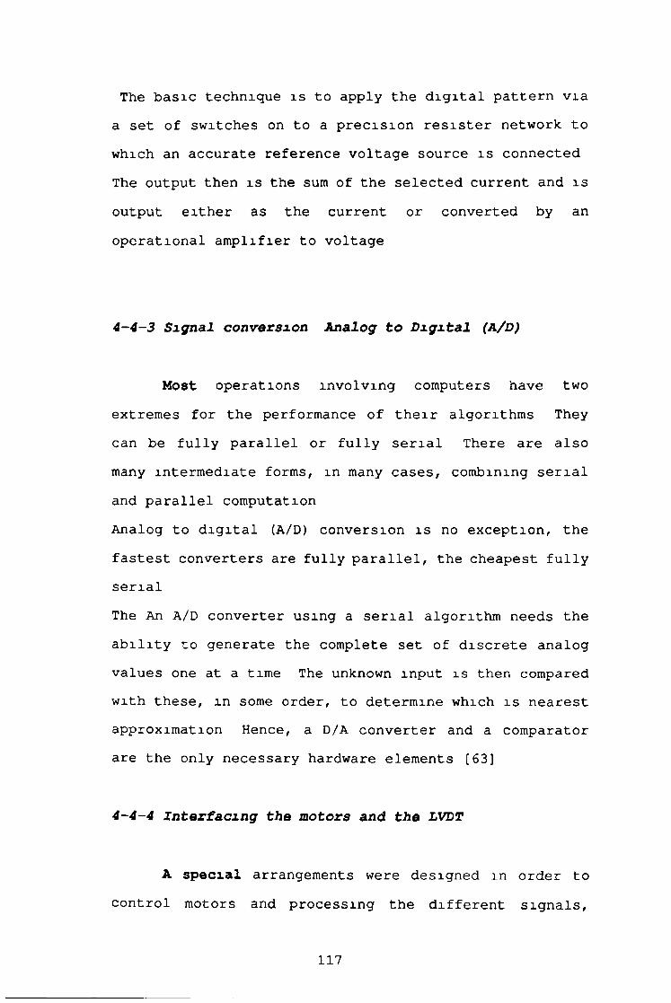
The b a s ic tech n iq u e i s t o apply th e d i g i t a l p a t t e r n v ia
a s e t o f sw itc h e s on to a p r e c i s i o n r e s i s t e r network to
which an a ccu ra te r e fe r e n c e v o l t a g e sou rce i s co n n ected
The output then i s th e sum o f th e s e l e c t e d cu rren t and i s
output e i t h e r as th e cu rren t or con verted by an
o p e r a t io n a l a m p l i f ie r to v o l ta g e
4 - 4 - 3 Signal conversion Analog to Digital (A/D)
Most o p e r a t io n s in v o lv in g computers have two
extrem es fo r th e performance o f t h e i r a lg o r ith m s They
can be f u l l y p a r a l l e l or f u l l y s e r i a l There are a l s o
many in te rm e d ia te forms, in many c a s e s , combining s e r i a l
and p a r a l l e l com putation
Analog to d i g i t a l (A/D) c o n v e rs io n i s no e x c e p t io n , th e
f a s t e s t c o n v e r te r s are f u l l y p a r a l l e l , th e ch ea p est f u l l y
s e r i a l
The An A/D c o n v e r ter u s in g a s e r i a l a lgo r ith m needs th e
a b i l i t y to g e n e ra te th e com plete s e t o f d i s c r e t e an a log
v a lu e s one at a tim e The unknown in p u t i s then compared
w ith t h e s e , in some order, to determ ine which i s n e a r e s t
approxim ation Hence, a D/A c o n v e r te r and a comparator
are th e on ly n e c e ssa r y hardware e lem en ts [63]
4 -4 -4 Interfacing the motors and the LVDT
A s p e c i a l arrangements were d e s ig n ed in order to
c o n tr o l motors and p r o c e s s in g th e d i f f e r e n t s i g n a l s ,
117

an a log and d i g i t a l , c o n s id e r in g th e v a r io u s p r e v io u s
p r i n c ip l e s and requirem ents
F igu re (4—1 2 ) , i l l u s t r a t e s t h e s e arrangement as two
s e c t i o n s , th e f i r s t one concern motors and c o n s i s t s o f
two m otors, a m p l i f ie r , p r o t e c t io n box and d i g i t a l to
analog co n v erter i s co n n ected to p e r so n a l computer
While the second s e c t i o n c o n s i s t s o f th e LVDT,
tra n sd u cer a m p l i f ie r , p r o t e c t io n box Analog t o d i g i t a l
c o n v e r te r and th e same p e r so n a l computer which i s
connected to d i g i t a l p r in t e r
A lso , two m eters were used t o m onitor th e change m th e
output and input The d e s c r ip t io n s o f t h e s e e lem en ts are
as fo l lo w s
4-4-4-1 Signal conversion Digital to Analog (D/A)
- DAC-02 Description
The co n v e r ter used t o change th e d i g i t a l s ig n a l
coming from th e computer to c o n tr o l th e movement and
v e l o c i t y o f th e motors was o f ty p e DAC-02
This card c o n s i s t s o f two se p a r a te double b u f fe r e d 12 b i t
m u lt ip ly in g D/A ch an n els p lu s i n t e r f a c e c i r c u i t y The D/A
c o n v e r te r s may be used w ith a f i x e d D C r e f e r e n c e s as
c o n v e n t io n a l D/A's on board r e fe r e n c e s o f -5 V and -10
V prov id e output ranges o f 0-5 V, 0-10 V, + / -5 V and + / -
10 V , and 4-20 mA fo r p r o c e s s c o n tr o l cu rren t lo o p s
A l t e r n a t i v e ly , th e D /A 's , may be op erated w ith a v a r ia b le
or A C r e fe r e n c e s ig n a l as m u lt ip ly in g D /A 's , th e output
118

Digital Digital GraphicPrinter Display
D/AConverter
Protection
Box
Amplifier
Signal Processing
PC
First Motor W1
(ml)
(m2)
Output
Digital tignai
A/DConverter
Protection
Box
InputAnalogSignal
TransducerAmplifier
L.V.D.T
Lever
second Motor
Figur« (4-12)Block di«9r«m of the inspection system.
119

i s th e product o f r e fe r e n c e and d i g i t a l in p u t s . With an
A C r e fe r e n c e , th e u n ip o la r o u tp u ts p ro v id e 2 quadrant
m u l t i p l i c a t i o n and th e b ip o la r o u tp u ts p r o v id e 4
quadrant, o p e r a t io n 12 b i t accu racy i s m ain ta ined up t o
1kHz. S in ce da ta i s 12 b i t s , da ta i s w r i t t e n t o each D/A
in 2 c o n s e c u t iv e b y te s The f i r s t b y te i s th e l e a s t
s i g n i f i c a n t and c o n ta in s th e 4 l e a s t s i g n i f i c a n t b i t s o f
data The second b y te i s th e most
s i g n i f i c a n t and c o n ta in s th e most s i g n i f i c a n t 8 b i t s o f
data The l e a s t s i g n i f i c a n t b y te i s u s u a l ly w r i t t e n ,
f i r s t and i s s to r e d in an in te r m e d ia te r e g i s t e r in th e
A/D, having no e f f e c t on th e output When th e most
s i g n i f i c a n t data and p r e se n te d " b ro a d s id e " t o th e D/A
c o n v e r te r thus a s s u r in g a s i g n a l s t e p update T h is
p r o c e s s i s known as double b u f f e r in g
The DAC-02 i s packaged on a 5" lon g { h a l f - s l o t } board
s u i t a b l e fo r u se in a l l models o f IBM P C S i t i s
ad d ressed as an I/O d e v ic e u s in g 8 I/O l o c a t i o n s , and may
have i t s I/O add ress s e t by means o f an on-board DIP
sw itc h t o any 8 b i t boundary in th e 255-1023 (decim al)
I/O address sp ace The board u s e s th e i n t e r n a l +5V, + 12V
and 12V computer s u p p l ie s and consumes 850 m i l l i - w a t t s o f
power [64] F igu re (4 -1 3 ) , i l l u s t r a t e t h i s card W hile,
Appendix (A 4-5 ), g iv e s i t s th e s p e c i f i c a t i o n
4-4-4-2 Signal conversion ANALOG TO DIGITAL (A/D)
Without t h i s board s i g n a l s from th e l i n e a r
v a r ia b le d i f f e r e n t i a l tra n sfo rm er (L V D T) , w i l l have no
120

rlgvr« 14*1»DIGITAL TO AXM 1O4 (D/A).
DAC-02

meaning, t h e r e f o r e a c o n v e r te r o f ty p e DASH-8 c o n v e r t s
th e analog s i g n a l s in to d i g i t a l one was s e l e c t e d .
- Description of the DASH-8
The dash-8 i s an 8 channel 12 b i t h ig h sp eed
c o n v e r ter and t im e r /c o u n te r board IBM.PC The DASH-8 board
i s 5 ” long and can be f i t t e d m a " h a l f " s l o t . A l l
c o n n ection are made through a s tan d ard 37 p in D male
con n ector th a t p r o j e c t s through th e rea r o f th e com puter.
The fo l lo w in g fu n c t io n s are implemented on th e DASH-8
( 1 ) - An 8 ch an n el, 12 b i t s u c c e s s i v e app rox im ation A/D
co n v erter w ith sample / h o ld The f u l l s c a l e in p u t
o f each channel i s ended w ith a common ground and
can w ith stan d a co n tin u o u s over lo a d o f + / - 30 v o l t s
and b r i e f t r a n s i e n t s o f s e v e r a l hundred v o l t s
A l l input are f a i l s a f e i e open c i r c u i t when th e
computer power i s o f f . A/D c o n v e r s io n t im e i s
t y p i c a l l y 25 m icrosecond (35 m icrosecon d max. ) and
depending on th e speed o f th e so f tw a r e d r iv e ,
through p u ts o f up to 3 0 .000 c h a n n e ls / s e c are
a t t a in a b le
( 2 ) - An 8253 programmable co u n ter t im er p r o v id e p e r io d ic
in te r r u p ts fo r th e A/D c o n v e r te r and can
a d d i t io n a l l y be used fo r ev en t c o u n t in g , p lu s and
wave form g e n e r a t io n , freq u en cy and p e r io d
measurement e t c There are th r e e s e p a r a te 16 b i t
down co u n te rs in th e 8253 One o f t h e s e i s co n n ec ted
122

t o a su b m u lt ip le o f th e system c lo c k , and a l l I/O
fu n c t io n s o f th e rem aining two are a c c e s s i b l e to th e
u ser
( 3 ) - 7 b i t o f TTL d i g i t a l I/O are p rov id ed composed o f
one output part o f a b i t s and one inp ut p o r t o f 3
b i t s
( 4 ) - P r e c i s io n +10 00 V o lt s ( t / - 0 / v ) r e fe r e n c e v o l ta g e
output i s d e r iv e d from th e A/D c o n v e r te r r e fe r e n c e
( 5 ) - An e x te r n a l in te r r u p t inp ut p rov id ed th e s e l e c t any
o f IBM P C in te r r u p t l e v e l s 2-7 and a l lo w s u ser
programmed in te r r u p t r o u t in e s t o p ro v id e background
data a c q u i s i t i o n or in te r r u p t d r iv en c o n t r o l The
DASH-8 in c lu d e s s t a t u s and c o n tr o l r e g i s t e r s th a t
make in te r r u p t handshaking a s im ple procedure The
in te r r u p t input may be e x t e r n a l ly co n n ected to th e
t im e r / counter or any o th e r t r i g g e r so u r c e .
(6) - IBM P C buss power (+5 ,+12 , 8-12v) i s p rov id ed
along w ith a l l o th er 1/0 c o n n e c t io n on th e rear
con n ector This makes fo r s im p le a d d it io n o f u ser
d es ig n ed i n t e r f a c e s , inp ut s i g n a l c o n d it io n in g
c i r c u i t s , e x p r e s s io n m u lt ip le x e r e t c F igu re (4 -1 4 ) ,
i l l u s t r a t e s t h i s card, [65] While Appendix (A 4-6 ) ,
g iv e s i t s s p e c i f i c a t i o n s
4 - 4 - 5 Specification of transducer amplifier type S7 M
The S7M i s an o s c i l la t o r /d e m o d u la to r (synchronous)
p r o v id in g e x c i t a t i o n and s ig n a l c o n d i t io n in g fo r a wide
range o f in d u c t iv e tr a n sd u c e r s , or when f i t t e d w ith an
123

• - u v a
•<a/v) lYxiDza oí ootony
< * T -» ) * x n 6 T 4

input o p t io n card , fo r r e s i s t i v e s t r a i n gauges A + /-1 0
output i s o b ta in a b le w ith s ig n a l in p u ts in th e range 50
mV t o 20V (lower w ith o p t io n z) High c u rren t output
o p t io n s p ro v id e + /-1 0 V a t 100 mA or 4-20 mA
In te r n a l c o n t r o l s s e t g a in and zero output (w ith up t o
100% su p p ress ion ) A lso in c lu d e d are z er o /r u n sw itc h ,
ov er-ra n ge in d ic a t o r (LED) and mounting p in s fo r e a s i l y
changing b r id g e inp ut o p t io n r e s i s t o r s and frequ en cy
s e l e c t i o n c a p a c ito r The input o p t io n in c lu d e s a ( s h u n t ) ,
c a l ib r a t io n sw itc h c o n n e c t in g an in t e r n a l p r e c i s i o n (59K)
r e s i s t o r , w ith an on-board r e la y a llow ed remote CAL
o p e r a tio n S e le c t o r l in k s a l lo w o p e r a tio n from 120 or 240
a c s u p p l ie s
The u n it i s s u i t a b l e fo r use w ith s t r a i n gauges and th e
com plete range o f R D P p r e ssu r e and AC-LVDT Transducers
[66] The t e c h n i c a l s p e c i f i c a t i o n o f t h i s a m p l i f i e r i s
g iv en m Appendix (A4-7)
4 -5 C a l ib r a t io n
There are two k in ds o f c a l i b r a t io n The f i r s t one i s
performed by th e m anufacturer, and th e second i s
performed by th e u s e r s Motors, a m p l i f i e r s , c o n v e r te r s ,
and tra n sd u cers r e q u ir e a s p e c i a l c a l i b r a t io n
The tra n sd u cer , o n ly w i l l be c o n s id er ed as an example
Transducer m anufacturer c a l i b r a t io n c e r t i f i c a t e in c lu d e s
l in e a r range, c a l tem, c a l loa d , s e n s i t i v i t y and
l i n e a r i t y The u se r c a l i b r a t i o n aims to f in d out a
c e r t a in formula to be used fo r a s p e c i f i e d purpose
125

* The l in e a r v a r ia b le d e f e r e n t i a l tran sform er (LVDT)
produces an e l e c t r i c a l output p r o p o r t io n a l to th e
disp lacem en t o f a se p a r a te movable core
The output v o l t a g e o f an (LVDT) i s a p r e c i s e l y l in e a r
fu n c t io n o f core d isp lacem en t over a s p e c i f i e d range o f
motion C onsequently , a p lo t o f output v e rsu s core
d isp lacem en t i s e s s e n t i a l l y a s t r a i g h t l i n e w ith in th e
s p e c i f i e d range o f motion Beyond th e nominal l in e a r
range, th e output b e g in s to d e v ia t e from a s t r a i g h t l i n e
in a g e n t l e curve User c a l i b r a t io n i s accom plish ed to
i n d ic a t e s th e l in e a r range Then u s in g an a c cu ra te
m easuring in stru m en t, th e r e l a t io n s h ip among th e output
and d isp lacem en t i s found [13]
T h e o r e t ic a l , r e l a t io n s h ip between output and
d isp lacem en t i s in th e form o f l in e a r e q u a t io n , in
g e n e ra l i t has th e fo l lo w in g form:
Y = F(x) (4 -15)
C a l ib r a t io n o f GT X 2500, was r ep ea ted f i v e t im e , F igure
(4-15) shows th a t th e c a l i b r a t io n r e s u l t i s o f a l in e a r
form as th e t h e o r e t i c a l one
4 -6 Softw are d e s ig n
Two se p a r a te programs were d e s ig n ed to f i t th e
purpose o f autom atic in s p e c t io n , th e f i r s t one i s to
c o n tr o l th e motor movements a t a c e r t a in t im e to a
126

Output (volts)
D i s p l a c e m e n t ( m m )
Senes 1
(LV DT),ca l ibra tion - 2 - Figure (4-15)

c e r t a i n p o s i t i o n s . W hile, th e secon d has d i f f e r e n t
t a s k s , l i k e p r o c e s s in g computing, comparing, d i s p la y in g ,
p r i n t i n g and p l o t t i n g th e r e s u l t s t h e s e programs were
w r i t t e n m th e BASIC language and th e y may be a l s o
co n v e r te d t o any o th e r la n g u a g e s .
128

CHAPTER FIVE
5-EXPERIMENTAL RESULTS
5 -1 The m easuring p r i n c i p l e .
The m easuring p r i n c i p l e o f th e au tom atic
m easuring system , i s based on moving a s t y l u s a t c o n s ta n t
v e l o c i t y a cro ss th e th r ea d p r o f i l e or th e h e l i x path The
r i s e and f u l l o f t h e s t y l u s i s d e t e c t e d e l e c t r o n i c a l l y
u s in g an e le c tr o m e c h a n ic a l s e n so r , th e s ig n a l i s then
a m p l i f ie d and i n t e r f a c e d t o a p e r so n a l computer
F igu re (5 -1 ) , shows th e r e l a t i o n s h i p between th e b o l t
movement and th e s t y l u s d isp la c e m e n t , fo r th e c a se o f
form in s p e c t io n , m which th e b o l t moves a t a c o n s ta n t
v e l o c i t y V2, w h ile t h e s t y l u s which i s f r e e t o move
v e r t i c a l l y , f o l lo w s th e th read form, th u s th e r i s e and
f a l l s o f the s t y l u s p r o v id e th e t r a c e o f th e th rea d form
A lso , f ig u r e ( 5 - 2 ) , shows th e r e l a t i o n s h i p between th e
b o l t movement and t h e s t y l u s d isp la ce m en t fo r th e c a s e o f
h e l i x in s p e c t io n In t h i s c a se th e b o l t r o t a t e s w ith a
c o n s ta n t angular v e l o c i t y , a t th e same t im e , i t i s moving
w ith a co n sta n t l i n e a r v e l o c i t y Vl; w h i le th e s t y l u s i s
f r e e to move on ly in th e v e r t i c a l d i r e c t i o n
129

S t y i u f .
f o n » .
f*r®ad l o t i o n v2
?i?ure
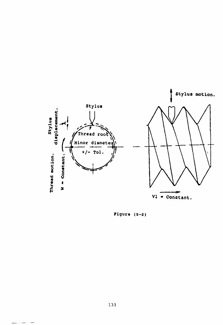
Thread motion.
Styl
us
Stylus motion
Figure (5-2)
131

5 -2 The o p e r a t io n a l c y c l e s
The in s p e c t io n p r o c e s s s t a r t s from th e i n i t i a l
p o s i t i o n and th e r e s u l t s are d is p la y e d , im m ediately a t
th e end o f each o p e r a t io n a l c y c l e .
The o p e r a t io n a l c y c l e s o f th e th read m easuring system
c o n s i s t s o f two b a s ic c y c l e s . These are*
( 1 ) - T h e h e l i x p a t h i n s p e c t i o n c y c l e .
( 2 ) - T h e t h r e a d f o r m i n s p e c t i o n c y c l e .
And each one o f them, c o n s i s t s o f th e fo l lo w in g s t e p s
1 - Clamping th e object
2- Stylus contact
3- Generating th e linear and the angular motions
4 - Generating the linear motion
5- Releasing th e object and displaying the results
5-2-1 Clamping the object
The f i r s t s t e p o f th e o p e r a t io n a l c y c l e s , i s
clam ping th e b o l t between th e f i x e d and movable jaws
F ig u re ( 5 - 3 a ) , shows t h a t , th e movable jaw should be moved
from a s p e c i f i e d p o in t ax to anoth er p o in t a2 m order to
perform th e clam ping s t e p a cco rd in g to th e s p e c i f i e d
d e s ig n p r e ssu r e The d i f f e r e n c e between ax and a2 i s
a lw ays c o n sta n t and equal to Xx fo r th e same ty p e o f
132

Stylus
• ' 1 c
Bolt
B Ovs •- Tabls
Figur« (5-3*)
0C QC
V6
Figur« (5-3o)The thread form inspection cycle
133

b o l t The p r e v io u s movement i s p rov id ed by motor number
one (mx) as a s p e c i f i e d key i s p r e sse d
The motor s t a r t s r o t a t in g c a u s in g advance movement o f th e
movable jaw which moves l i n e a r l y by th e e f f e c t o f th e
i n t e r n a l guidance i n s id e th e f i x e d c y l in d e r , U n t i l i t
g e t s t o th e second p o in t a 2
D if f e r e n t v e l o c i t i e s can be a p p l ie d t o th e movable jaw,
one o f t h e s e v e l o c i t i e s i s V 2 which eq u a ls 25 mm/sec and
r e p r e s e n t s th e maximum l in e a r v e l o c i t y
A lso , th e d i s ta n c e X x between th e p o in t a x and th e p o in t
a 2 can be in c r e a se d or d ecreased and i t depends on th e
b o l t s i z e
5-2-2 Stylus contact
The s t y l u s c o n ta c t , r e p r e se n ts th e second s t e p o f
th e o p e r a t io n a l c y c l e s , see f ig u r e ( 5 - 3 b ) .
As soon as th e clam ping jaw advances w ith a c o n sta n t
v e l o c i t y Vx to clamp th e b o l t , th e s t y l u s advances w ith a
c o n s ta n t v e l o c i t y V2 from p o in t (b x) t o p o in t (b2) which
i s th e r e fe r e n c e p o in t o f th e m easuring system
A lso , th e d i f f e r e n c e between p o in t b x and p o in t (b2) ,
always e q u a ls to th e c o n sta n t d i s ta n c e Yx.
5-2-3 Generating the linear and the angular m o t i o n s .
T h is s t e p aims to perform th e h e l i x path
134

in s p e c t io n Once th e s t y l u s approaches th e r e f e r e n c e
p o in t a t the root o f th e th r ea d , i t t r i g g e r s a micro
sw itc h fo r s t a r t in g motor number two (m2) , as shown m
f ig u r e ( 5 - 3 c ) , which p r o v id e s th e l in e a r m otion t o th e
b o l t t a b l e thereby moving i t w ith a c o n sta n t v e l o c i t y .
The b o l t r o ta t e s w ith a c o n s ta n t angular v e l o c i t y , a t th e
same tim e the s t y l u s moves a lo n g th e h e l i x p a th , from
p o in t b 2 w ith a c o n s ta n t l in e a r v e l o c i t y V4 u n t i l i t g e t s
to p o in t b 3, which r e p r e s e n t s th e end o f t h i s s t e p
The in s p e c t io n tim e and th e t r a v e l l i n g d i s t a n c e are
c o n t r o l l e d through th e so ftw a re which are d e s ig n e d w ith
th e c a p a b i l i t y o f p r o v id in g a number o f d i f f e r e n t angu lar
and l in e a r v e l o c i t i e s which are req u ired to s e l e c t th e
optimum c o n d it io n s fo r o p e r a t in g t h i s system
5-2-4 Generating the linear motion
When the s t y l u s t r a v e l s t o p o in t b 3, i t t r i g g e r s
aga in another micro s w it c h e s . The f i r s t micro sw itc h
s to p s motor number one (ir^), w h ile th e second micro
sw itc h r e v e r se s th e r o t a t in g d i r e c t io n o f motor number
two (m2) . The s t y l u s t r a c e s t h e form o f th e th r e a d w ith
a c o n s ta n t v e l o c i t y V6 when i t moves from p o in t b 4 t o b 1
as shown m f ig u r e s (5-4a) and ( 5 - 4 b ) .
5-2-5 Releasing the object and displaying the re su lt s .
As soon a s , motor number two (m2), s to p s a t p o in t
135

XI
Al
r i
<t -
g
V2 f Y1
EX-1 Vl
«2
Bolt I
Tftbl* -,___ V3
ai
02
« « . p i n , J . « ? i g u r * ( 5 ’ 4 a >
Figur« (5-4b)
QC s
B CFigur« (5-4o)
The helix inspection cycle.
136

b l , an order i s g iv e n to motor number one (Hi!) to s t a r t
r o t a t in g m order t o withdraw th e movable jaw t o i t s
i n i t i a l p o s i t i o n . The same o p e r a t in i s perform ed on th e
s t y l u s , and th e r e s u l t s o f i n s p e c t in g e i t h e r th e h e l i x
path or th e form are d is p la y e d on th e sc r e e n and then
p l o t t e d or p r in t e d as r eq u ire d . See f i g u r e (5 -4c)
5-3 E xp erim enta l procedure.
The ex p er im en ta l procedure in c lu d e s , c a l i b r a t i o n s
and recom m endations.
5 -3 -1 Calibrations
Two d i f f e r e n t k inds o f c a l i b r a t i o n p roced u res are
req u ire d fo r th e autom atic m easuring sy stem . The f i r s t
c a l i b r a t i o n procedure i s fo r th e e l e c t r o n i c e lem en ts
which i s n e c e s s a r y fo r d e v e lo p in g th e so f tw a r e And th e
second c a l i b r a t i o n procedure i s fo r th e m echan ica l
mechanisms. This i s n e c e ss a r y b e fo r e s t a r t i n g th e
o p e r a t io n a l c y c l e s fo r each b o l t s i z e .
(1)- Calibration of the electronic elements
One of the electronic elements which requires. Calibration is the linear variable differential transformer (LVDT). The calibration of this element is the most important, because it affects the software and signal processing. The (LVDT) calibration is required to
137

f in d out th e r e l a t io n s h ip between th e output o f th e
(LVDT) so an e l e c t r i c a l s i g n a l s ( v o l t s ) and th e
e q u iv a le n t d i s ta n c e q u a n t ity as d isp la ce m en t , g iv e s as
m etr ic u n i t s This r e l a t io n has been used fo r d e v e lo p in g
th e v a r io u s so ftw a re
The tra n sd u cer a m p l i f ie r S7M has been c a l ib r a t e d t o g iv e
an output m one d ir e c t io n o n ly , and th e c a l i b r a t i o n
procedure i s o u t l in e d in the m anufacturer c a ta lo g u e
F in a l ly , th e two c o n v e r te r s ( DASH-8 and DAC-02 ) , have
been c a l ib r a t e d accord ing t o th e m anufacturer
s p e c i f i c a t i o n
(2)- Calibration of the mechanical elements
The l e v e r and th e clam ping mechanisms sh ou ld be
c a l ib r a t e d once b e fo r e o p e r a tin g th e system
These c a l i b r a t io n are req u ired in order to a d ju s t th e
d is ta n c e x lf between th e movable jaw and th e s id e o f th e
b o l t A lso th e same, i s r eq u ired fo r th e d i s ta n c e Ylf
between th e s t y l u s t i p and th e r e fe r e n c e p o in t b 2
The mam d i f f e r e n c e between c a l i b r a t i n g an e l e c t r o n i c
elem ent and a m echanical one i s t h a t e l e c t r o n i c e lem en ts
are c a l ib r a t e d on ly once b e fo re d e v e lo p in g th e d i f f e r e n t
so ftw a re and no need to c a l i b r a t e them aga in u n le s s
o th e rw ise a d e f e c t or f a i lu r e i s d e t e c t e d when th e y are
working
While th e m echanical c a l i b r a t io n sh ou ld be r ep ea ted
when another s i z e o f b o l t i s r e q u ire d to be in s p e c te d
138

\
The recommendation and n o te s in c lu d e th e d i f f e r e n t
ch eck in g s t e p s which must be accom plish ed b e fo r e
o p e r a t in g th e m easuring system These s t e p s form th e
s a f e t y f a c t o r o f u s in g t h i s sy stem , a t th e same t im e ,
in c r e a s e th e accuracy o f th e sy s tem . T h erefore , th e
f o l lo w in g e lem en ts must be check ed , m order t o en su re
th a t th e y are f i x e d w ith in th e hand t ig h t e n e d f o r c e s :
( 1 ) - The g e n e r a l b a s e .
( 2 ) - The s t y l u s .
( 3 ) - The l in e a r v a r ia b le d i f f e r e n t i a l tra n sfo r m er .
( 4 ) - A l l a d j u s t in g b o l t s .
A lso , i t i s n e c e s s a r y to en su re t h a t a l l e l e c t r i c a l
c o n n e c t io n are f i x e d in th e r ig h t p o s i t i o n o f t h e s e are*
1 - Motor c o n n e c t io n s
2 - LVDT c o n n e c t io n s
A fte r t h a t , i t i s p r e f e r a b le t o t r y o n ly one
o p e r a t io n a l c y c l e , and compare th e r e s u l t s w ith th e
t h e o r e t i c a l one to en su re th a t th e m easuring system i s
working w ith in th e d e s ig n s p e c i f i c a t i o n s .
5 -4 I n s p e c te d o b j e c t s .
The in s p e c t e d o b j e c t s used fo r th e e x p e r im e n ta l ,
5-3-2 Recommendations
139


were a s e t o f an ISO m etr ic male screw th rea d (b o l t )
These b o l t s were o f 6g c l a s s , and t h e i r l i m i t s and
to le r a n c e s are g iv en by th e t a b l e (5 ) , o f s e c t i o n f o u r -
screw th r ea d s (BS 3643 ) . Some o f t h e s e b o l t s were
m anufactured by tu r n in g The o th e r were m anufactured by
r o l l i n g
D i f f e r e n t s i z e s o f t h e s e b o l t s were in s p e c te d u s in g t h i s
autom atic m easuring sy stem . The minimum s i z e was M3.
While th e maximum s i z e was M36 The s p e c i f i c a t i o n s o f
t h e s e b o l t s are g iv e n in th e BS 3643
5-5 Linear and angular velocities.
Two ty p e s o f v e l o c i t i e s are req u ired to perform th e
form and h e l i x path i n s p e c t i o n s .
The minimum l in e a r v e l o c i t y u sed fo r form in s p e c t io n was
o f range 0 5 mm/sec and th e minimum angular v e l o c i t y used
fo r h e l i x in s p e c t io n was o f range o f 1 .4 8 r a d /s e c W hile
th e maximum l in e a r v e l o c i t y used fo r form in s p e c t io n was
o f range o f 2 mm/sec, and th e maximum angular v e l o c i t y
used fo r h e l i x path in s p e c t io n was o f range 6 25 r a d / s e c
o th er v e l o c i t i e s w i l l be i l l u s t r a t e d through th e f i g u r e s
which are r e p r e se n te d our ex p er im en ta l r e s u l t s .
Form and h e l i x pa th i n s p e c t io n s were performed fo r th r e e
d i f f e r e n t s i z e s o f an ISO m e tr ic screw th read s ( B o l t s ) ,
t h e s e are c o n se q u en t ly : M6, M8 and M16.
5-6 Experimental results.
141

5-6-1 Experimental results of M6
Three d i f f e r e n t v e l o c i t i e s were used to perform
th e in s p e c t io n s t h e s e were 0 .5 , 0 83 and 1 .2 5 mm/sec
W hile on ly two angular v e l o c i t i e s were used fo r h e l i x
in s p e c t io n t h e s e were. 3 13 and 8 .3 3 r a d / s e c
i5-6-1-1 Form inspection
F igu re ( 5 -5 ) , shows th e r e s u l t o f in s p e c t in g
th e form o f M6 u s in g th e lo w e s t v e l o c i t y 0.5 mm/sec.
A lso , f ig u r e ( 5 - 6 ) , i l l u s t r a t e s th e r e s u l t s o f in s p e c t in g
th e same b o l t u s in g another v e l o c i t y 0 .8 3 mm/sec While
f i g u r e (5-7) r e p r e se n t th e r e s u l t s o f th e same thread
u s in g v e l o c i t y eq u a l to 1 25 mm/sec.
5-6-1-2 Helix path inspection
F igu re ( 5 - 8 ) , i l l u s t r a t e s r e s u l t o f in s p e c t in g
th e h e l ix path o f M6 u s in g angu lar v e l o c i t y equal to
3 125 r a d /s e c fo r one thread o n ly . W hile f i g u r e (5 -9 ) ,
shows the v a r ia t i o n o f th e same b o l t fo r f i v e th read s
u s in g an angu lar v e l o c i t y equal to 3 125 r a d / s e c .
5-6-2 Experimental results o f MQ
Five d i f f e r e n t l in e a r v e l o c i t i e s were used to
perform th e t a s k o f form i n s p e c t i o n s . These are
c o n se q u en t ly ( 0 .5 , 0 83, 1 25, 1 66 and 2 ) mm/sec.
142

H (mm)
17H/24 = 0.606 mm H = 0.865 mm P = 0.989 mm
Figure (5-5)FORM inspection of
M6, velocity 0.5 mm/sec.
143

H = 0.853 mm P = 0.985 mm
17H/24 = 0.604 mm
Figure (5-6)FORM inspection of
M6/ velocity 0.83 mm/sec
;144

H (mm)
17H/24 = 0.601 mm H = 0.848 mm P = 0.980 mm
= 29.989
Figure (5-7)FORM inspection of
M6, velocity 1.25 mm/sec
145

146
3 * 18.60 no MAX.d«v.- 0.052 w
Y
Figure (5-8)HELIX inspection of
M6# one revolution, w=3.125 rad/sec

147
s -MAX.dev.«
94*2460.051
25 50 75 100Figure (5-9)
HELIX inspection of M6, five revolution, v=3.i25 rad/sec

A lso two d i f f e r e n t angu lar v e l o c i t i e s were fo r in s p e c t in g
th e h e l i x path o f th e same th rea d , t h e s e are
5-6-2-1 Form inspections
F igu re (5 -1 0 ) , i l l u s t r a t e s th e r e s u l t o f
in s p e c t in g th e form o f th e b o l t M8 u s in g a very slow
v e l o c i t y 0 .5 mm/sec. The o th e r r e s u l t which i s shown in
f ig u r e (5-11) r e p r e s e n t s th e s low v e l o c i t y which equal to
0 .8 3 mm/sec The r e s u l t o f u s in g a medium v e l o c i t y equal
t o 1 25 mm/sec can be seen in f ig u r e (5-12) . The high
speed 1 66 mm/sec g i v e s th e r e s u l t s shown m f ig u r e
(5-13)
5-5-2-2 Helix path inspection
F igu re (5 -1 4 ) , shows th e v a r ia t io n o f th e h e l i x
path due t o an angu lar v e l o c i t y o f 2 84 r a d /s e c , fo r f i v e
th r e a d s , a l s o f ig u r e (5 -1 5 ) , shows th e v a r ia t io n fo r one
t o o t h on ly o f th e same s i z e and due to th e angular
v e l o c i t y wl The r e s u l t s o f u s in g an angular equal to W2
= 6 25 r a d /s e c , fo r f i v e th r ea d s are shown on f ig u r e
( 5 - 1 6 ) , a l s o f ig u r e (5-17) shows th e r e s u l t o f th e same
b o l t and th e same v e l o c i t y but o n ly fo r one th r e a d .
5-6-3 Experimental results o f M 16
Five d i f f e r e n t l in e a r v e l o c i t i e s used t o in s p e c t
th e form o f t h i s s i z e , th e same v e l o c i t i e s were used to
\ 148
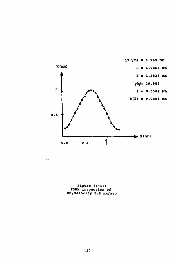
H(mm)
1 ■
0.5 ■
0.0 0.5 1
17H/24 = 0.769 mmH = 1.0855 mmP = 1.2535 mm
29.989I = 0.0501 mm
d(I) = 0.0001 mm
^ P(mm)
Figure (5-10)FORM inspection of
M8,velocity 0.5 mm/sec
149

H(mm)
0.
H - 1 .0884 nun
17H/24 - 0 . 7 7 1 nun
Figur« (5-11)FORM inspection of
M8, v«locity 0.83 nun/sec
150
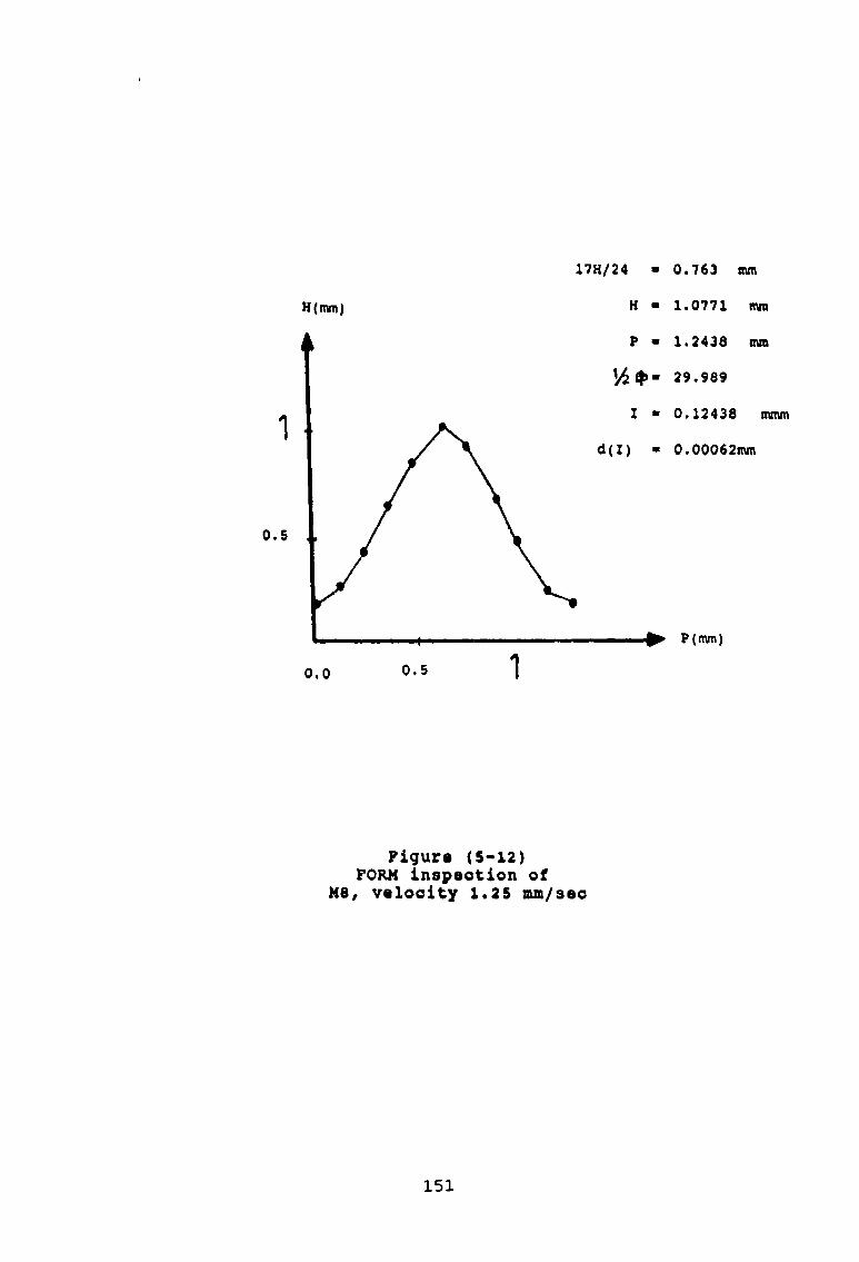
H(mm) H • 1.0771 mm
17H/24 ■ 0 . 7 6 3 mm
P(mm)
0.0 0.5
Figure (5-12)FORM inspection of
M8, velocity 1.25 mm/sec
151

H • 1.0942mm
17 H/24 • 0.776mmH(mra)
Figur« (5-13)FORM inspection of
M8, velooity 1.(6 nun/sec
152

153
S- 125.66 MAX.dev.« 0.062MIN.dev.« 0.050
Figxire (5-14)HE1IX inspection of
MB, five reolution, v=2. 8 4 rad/sec

154
s -
MAX.dav.-
HIH.dav.-0.0470.0SS
2 5 .1 3 2
25Figure (S-iS)
HILEX inspection of M8, one revolution, w=2.84 r&6/sec

___________

125
Figure (5-16)HELIX inspection of
M8, five revolution, v=6.25 rad/sec

S - 25.132 MAX.dev.- 0.0725 MIN. dev.- 0.080
X
25
Figure (5-17)HELIX inspection of
M8, one revolution, v=6.25 rad/sec
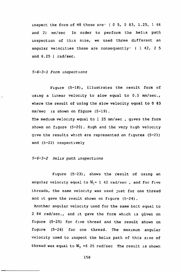
inspect the form of M8 these are* ( 0 5, 0 83, 1,25, 1 66 and 2) mm/sec In order to perform the helix path inspection of this size, we used three different an angular velocities these are consequently• ( 142, 2 5and 6.25 ) rad/sec.
5-6-3-1 Form inspections
Figure (5-18), illustrates the result form of using a linear velocity to slow equal to 0.5 mm/sec., where the result of using the slow velocity equal to 0 83 mm/sec is shown on figure (5-19).The medium velocity equal to 1 25 mm/sec , gives the form shown on figure (5-20) . High and the very high velocity give the results which are represented on figures (5-21) and (5-22) respectively
S-6-3-2 Helix path inspections
Figure (5-23), shows the result of using an angular velocity equal to W x= 1 42 rad/sec , and for five
threads, the same velocity was used just for one thread and it gave the result shown on figure (5-24).Another angular velocity used for the same bolt equal to
2 84 rad/sec., and it gave the form which is given on figure (5-25) for five thread and the result shown on figure (5-26) for one thread. The maximum angular velocity used to inspect the helix path of this size of thread was equal to W 3 =6 25 rad/sec The result is shown
158

H (mm)
4,.._ .. ■ - -— ■*..
1. 2.
Figure (5-18)FORM inspection of
Ml«, velocity 0.5 na/sec
159

H(mm)4
H-------------------1------------------- 1-
1 2
Figure (5-19)FORM inspection of
M16, velocity 0.83 mm/sec
160

H(mm)
, 4.. -- 4--------------«... *
1 2
Figur« (5-20)FORM inspection of MIC, velocity 1.25 nun/sec
161

H (mm )
Figure (5-21)FORM inspection of
M16, velocity 1.66 nun/pec
162
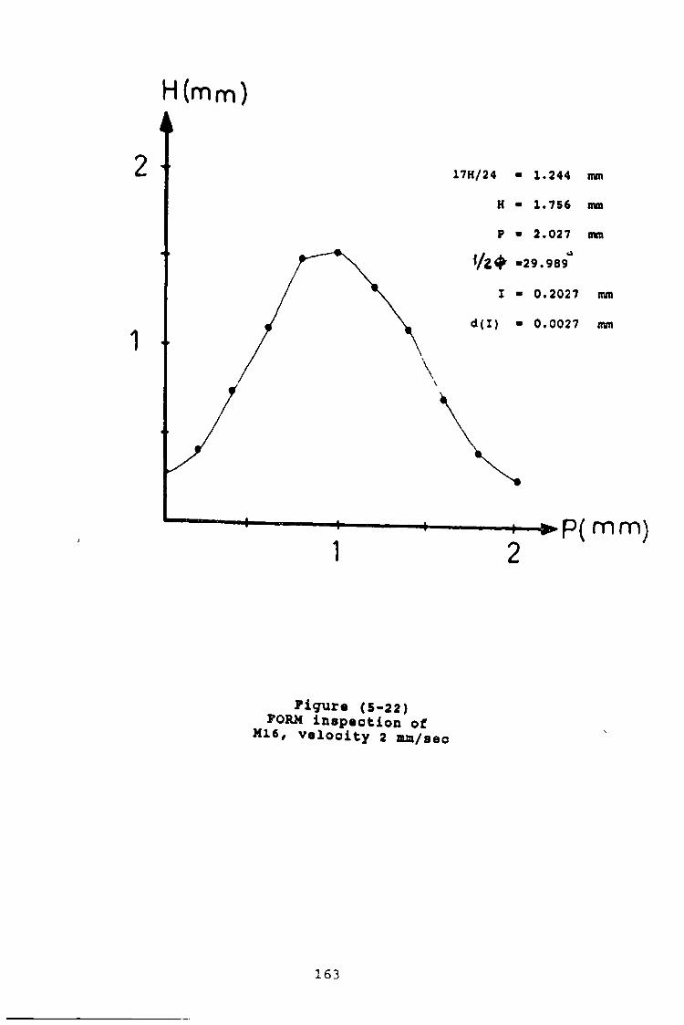
H (mm)
Figura (5-22)FORM inspection of
M16, velocity 2 mm/sec
163

164
S - 251.32 onMAX.dav." 0.092 mm
F i g u r e ( S - 2 3 )H E L IX i n s p e c t x n o f H 1 6
f i v e r e v o l u t i o n , w = i . 4 2 r a d / s e c

165
5 ® 50*042 cmMAX.dev.» 0.125 an
50
F i g u r e ( 5 - 2 4 )H E L IX i n s p e c t i o n o f M l<
o n e r e v o l u t i o n , v = l . 4 2 r a d / s e c

166
150
00
\
U L
S * 250 onMAX* dev.» 0*125 mmMIN.dev. ■ 0.060 mm
T ■ 12 sec
T T J T J Y T ~
: L k ' 1
v . .
CL
-15C?-
100
LL
250X mm
F i g u r e ( 5 - 2 5 )H E L IX i n s p e c t i o n o f M 16
f i v e r e v o l u t i o n , v = 2 . 8 4 r a d / s e c

>c
0
D
50Figure (5-26)
HELIX inspection of K16 one revolution, v=2.84 rad/sec

on figure (5-27) for five threads.
5-6-3-3 Artificial defect on the crest of Ml6
An artificial defect was made on the crest of the thread Using three different velocities this defect detected, figure (5-28), shows the form obtained at 0 83 mm/sec linear velocity
S-6-3-4 Artificial defect on the helix path of M16
Also another type of defect was done at the root, using two different angular velocities this defect detectedFigure (5-29), shows the variation of the two velocities
168

169
F i g u r e ( 5 - 2 7 )H E L IX i n s p e c t i o n o f M 16
f i v e r e v o l u t i o n , v = 6 „ 2 5 r a d / s e c

H WTO
00mm
figure (5-28)
170

171
MAX
MIN
figure (5-29)
CHAPTER S IX
6 - RESULTS & DISCUSSION
6-1 Discussion of the experimental resultsThe experimental results shown in chapter five will
be discussed and analyzed m this chapter, in order to find out the following.
(a)- The factors which effect the accuracy of the system
<b)- The behaviour of the stylus movement due to the different velocities
(c)- To select the optimum velocity required for each bolt size
<d)~ To find the relationship between the degree ofaccuracy and the different parameters of the bolt (pitch, depth of the thread, etc )
Therefore, the discussion will be divided under the following sections
(1)- The form inspection results.(2)- The helix path inspection results(3)- The artificial defects (form, helix path)
The previous test was repeated three times for the
172

profile form cases While the helix path test was repeated five times
6-2 The form inspection results
A very slow, slow, medium, high, and a very high velocities were provided in order to perform the profile form of the bolts M6, M8 and M16 Therefore each bolt size test will be discussed separately
6-2-1 The result of the bolt M6
This bolt was manufactured by rolling Its theoretical profile form is shown in figure (6-1), This is based on the BS 3643, part one and two of the ISO metric screw threads The very slow, velocity 0 5 mm/sec firstly was provided
m order to perform the profile form of this bolt size The result of this, were compared with the BS 3643, and they were within the specified tolerance zones While the actual profile form was developed depending onthe previous mentioned results Then, the actual profile
(form was superimposed on the theoretical one for comparison The comparison, shows that the actual profile form is m a good agreement with the theoretical one This may be due the high accuracy provided due to the very slow motion
iThe difference between the theoretical and the actual pitch is 0 0114 mm And the difference between the
173

H(mm)
P (mm)
Figure (6-1) Theoretical profile form of M6
174

theoretical and the actual depths is 0.007 nun. Therefore these differences can not be distinguished on the actual profile form as shown in figure (6-2)Also, the difference between the theoretical and actual increments is 0 0006 mm, and this is a very small value. This difference explains the good agreement between the theoretical and actual profile form Finally, the stable running of the stylus is another reason which explains the good accuracyIn order to reduce the inspection time of the operational cycle, a slow velocity 0 83 mm/sec was provided The result of this test were compared with the BS 3643 and they were within the specified tolerance zones Also the differences between the results of this test and the previous one is very small, if they are compared to each otherHowever, the actual profile form was developed according to these results After that it was superimposed on the theoretical one for comparison The difference between the theoretical and actual pitch has been increased by 0 003 mm, compared with the previous one Also, the difference between the theoretical and actual
depth has been increased to 0 005 mm, compared with the previous oneThe difference between the theoretical and actual increment, still very small and 'is equal to 0 0013 mm Also, the stylus has a stable running due to this velocity Therefore the actual profile form has, also a good agreement with the theoretical one as shown in
175

H(mra)
0 0 0 5
Figure (6-2)
176

In order to reduce further the time of the operational cycle, the previous velocity ( 0 83 mm/sec ) wasincreased to 1 25 mm/sec The results of this test were compared with the standard one in the BS 3643, and they were within the specified tolerance zones Figure (6-4), illustrates the actual profile form which is superimposed on the theoretical one The comparison shows the noticeable deformation of the actual profile form at the crest and the root of the tooth This is due to the increase in the velocity by 0 42 mm/sec, compared with the slow one And by 0 75 mm/sec, compared with the very slow velocity ( 0.5 mm/sec ) This also affects the response time of the linear variable differential transformer ( LVDT )Also the stylus due to this velocity does not have the same stable running as in the two previous tests While the difference between the theoretical and the actual increment was increased from 0 0006 mm due to the very slow velocity to 0 003 mm However the results are good and the actual form is in
good agreement with the theoretical oneTwo different velocities, (1 66 and 2 mm/sec) , also were used m order to reduce more and more the inspection time of the operational cycle Unfortunately the results due to these velocities were very changeable and they were out of range to be discussed or analyzed Therefore these velocities will not be used for this bolt size Table (6-1), gives a summary for the different tests of
figure (6-3)
177

H(nun)
Figure (6-3)
178

H(nun)
Figure (6-4)
179

T a b l e ( 6 - 1 )
ACTUALV 17H/24 H p .5 <$ I.5 .606 .865 .989 29.9 .0494.83 .604 .853 . 985 29.9 .0820
1.25 .601 .848 .980 29.9 . 1221.66 X X X X X2 X X X X Xd (17H/2 4) d (H) d(P) d<«>) d(I)
1 .00744 .01 .011 39. 6" . 00062 .00944 .013 .015 39.6" .00133 .01244 .018 .02 39.6" .0034 X X X X X5 X X X X X

00 X X
I
Theoreticalt 17H/24 H P • 5 <$ I2 .051.2 .083.613 .866 1 30 .125
X X 180

this bolt sizeIn which a comparison was made between the theoretical parameters and the actual one However the following points can be obtained from this table
(1)- When the velocity mcreasesf the accuracy of
the results decreases
(2)- The good agreement between the theoretical and
actual profile form can be achieved due to the
very slow and slow velocities for this bolt
size
(3)- The medium velocity 1 25 mm/secf can be provided
where the time is very important and less
accuracy is required
6-2-2 The results of the bolt size H8
In order to discuss the different tests of this bolt, the previous procedure was adopted, also the same steps were be repeated subsequentlyThe theoretical profile form of this bolt size is shown in figure (6-5) While the actual profile forms, which were superimposed on the theoretical one for comparison, are given consecutively m figures (6-6), (6-7) and(6-8) Their results were within the specified tolerance
zones Also, each one of the actual profile form has a good agreement with the theoretical one The reasons are the same as they are mentioned previously, in order to explain cases, one and two of the bolt size M 6 Also, a
181

(
H(nun)
Figure (6-5)The theoretical form of M8
182

H (mm)
P (mm)
Figure (6-6)
183
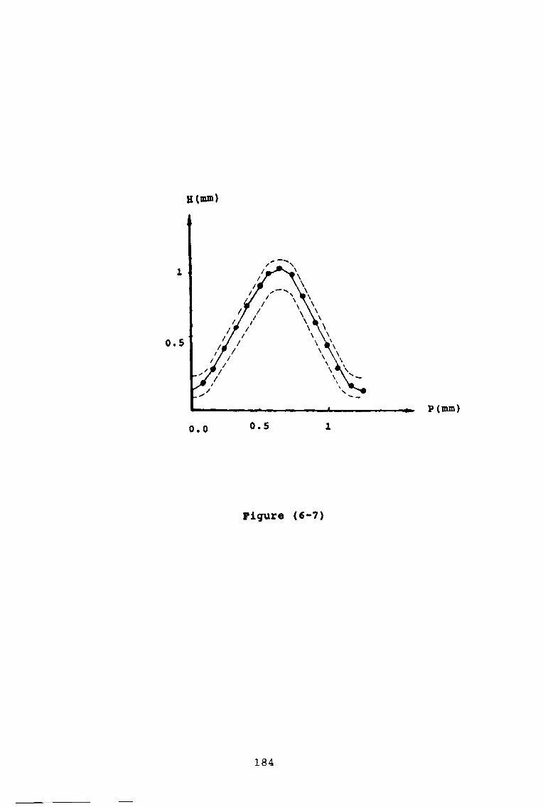
H(mm)
P(mm)
Figure (6-7)
184

H(mm)
P (mm)
Figure (6-8)
185

high velocity of 1.66 mm/sec was used in a new attempt to reduce the inspection time of the operational cycle. The results were compared with the reference one and they were within the specified tolerance zones Figure (6-9), illustrates the actual profile form of this test The comparison shows that the actual profile form has a specified deviations at the crest and root areas Also the profile form (actual) consists of three areas, on each side The affect of the increment explain some of these deviations While the bounce of the stylus due to this velocity is another reason of this deviation However, table (6-2), gives a summary of for previous tests
The maximum difference between the actual and theoretical pitch is 0 0134 mm And the minimum difference is 0 0035 mm Thus the difference between the maximum and minimum one is 0 0099 mm Also the maximum difference between the actual and theoretical one is 0 01 mm and the minimum difference between the maximum and minimum is 0 007 mm. The difference between the increment is 0 0001 mm due to the very slow velocity and 0 0004 due slow one, 0 00062 mm due to the medium And it was 0 0018 mm due to the high velocityThe minimum inspection time was achieved due to the maximum velocity while the maximum time was due to the very slow velocity As shown in case number (1) , and number (4)
6-2-3 The results of the bolt size M16
186

(
H(mra)
Figure (6-9)
187

Table (6-2)
V 17H/2 4 H p .5 <$ I T.5 .769 1.085 1.253 29.9 .0501 2.83 .771 1.088 1.256 29.9 .0833 1.5
1.25 .763 1.077 1.243 29.9 .124 11. 66 .776 1. 094 1.264 29.9 .158 .7532 X X X X X X
d(17H/24) a<H) d(P) d«<>) d(I)1 .0022 .003 .0035 39.6" .0t>012 .0042 .0059 .0068 39.6° .00043 .0038 .0054 .0062 39.6° .000624 .0092 .0117 .0143 39.6” .0075 X X X X X

T h e o r e t i c a l
17H/24 H P .5(J> I.05 • 0833
.766 1.082 1.25 30 .125.156X

This bolt was manufactured by turning Its theoretical profile form is given in figure (6-10) The first test for this bolt size was carried out at the very slow velocity 0 5 mm/sec. Then the results were compared with the standard one, and they were within the specified tolerance zones Also, the actual profile form which was developed according to these results, has superimposed on the theoretical form for comparison. The comparison as shown m figure (6-11), shows good agreement between the theoretical and actual profile form In the second test, the slow velocity 0 83 mm/sec, was used Also the results were compared with the reference one and they were within the specified tolerance zonesThe actual profile form of this test is shown in figure (6-12) This figure shows the actual profile form superimposes on the theoretical one The comparison illustrates that there is a good agreement between these profile forms The main reasons were mentioned previously The third test was carried out at medium velocity 1 25 mm/sec. The results were compared with the same standard and they were within the specified tolerance zonesIn figure (6-13), the comparison shows that the actual profile form, also has a good agreement with the theoretical one After that the test was performed at the high velocity 1 66 mm/sec in order to reduce further the inspection time of the operational cycle The results of this test were compared with the BS 3643 and they were
189

(mm)
Figure (6-10)The theoretical form of M16
190

H (mm)
F i g u r e ( 6 - 1 1 )

H (mm)
F i g u r e ( 6 - 1 2 )

H (mm)
Figure (6-13)
i
193

within the specified tolerance zones Also, the actual profile form was superimposed on the theoretical one for the comparison, as shown in figure (6-14)The comparison shows that the actual profile form still has a good agreement with the theoretical one m spite of the noticeable deformation at the crest and the root of the tooth In fact the first deformation was started from the third test. But it was not out of range and can not be discussed or analyzed However, one of the most important reasons is the bounce, which forced the stylus to miss some points especially at crest and root areas of the tooth profile In order to reduce the inspection time further moreThe very high velocity 2 mm/sec was provided to perform
the fifth form inspection Similarly, the results were compared with the reference one, and they were within the specified tolerance zones And also these results are the same of the previous one due to the slow velocity Thus, the same discussion can be seen adopted for this test. But the profile form was not the same More deformation can be seen at two different areas Also these, because of the bounce acts and the response time of (LVDT) These were explained previously Figure (6-15)Table (6-3), gives a summary of the different results
due to the various velocities The maximum difference between the actual and theoretical pitch was 0 068 mm, and the minimum one 0 0279 mm So, the actual difference between the maximum and the minimum was 0 0401 mm While the difference between the actual and theoretical
194
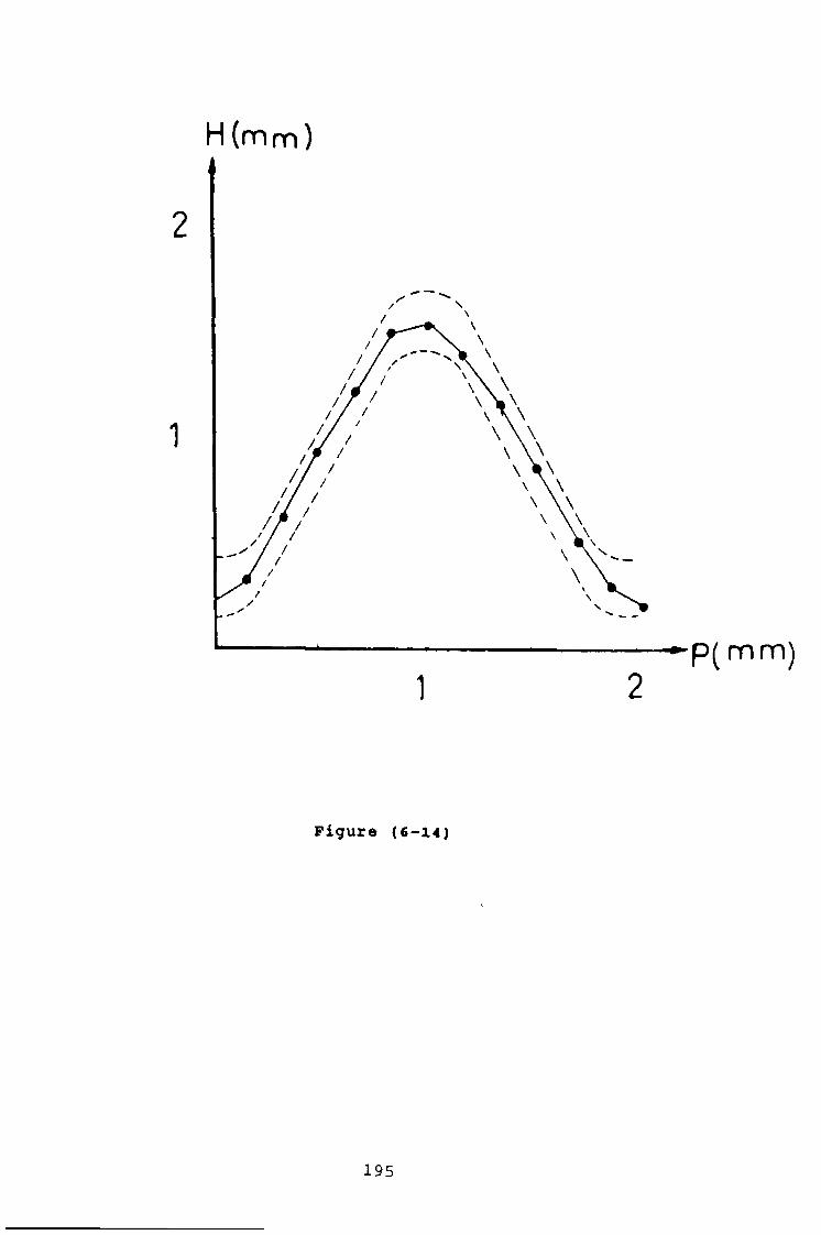
H (mm)
1 2
Figure (6-14)
195

H (mm )
F i g u r e ( 6 - 1 5 )

Table (6-3)Actual
V 17H/24 H P .5 <p I. 5 1.207 1.703 1.976 29.9 .0491.83 1.244 1.756 2.027 29.9 .08111.25 1.269 1.790 2.068 29.9 .1291.66 1.257 1.774 2.049 29.9 .1702 1.244 1.756 2.027 29.9 .202 1
d(17H/24) d(H> d(P) <*(<*>>1 .0199 .0291 .033 39.6”2 .0171 .0239 .0279 39.6”3 . 0421 .0579 .068 39.6”4 .0301 .0419 .049 39.6”5 .0171 .0239 .0279 39.6”

/
Theoretical T 17H/24 H P .5 4) I4 .052.4 1.226 1.732 2 30 .081.6 .1251-2 .166
.2
d(I). 0009 . 0011 .004 .004 .0027
197

depths the maximum one was 0 042 mm and as a minimum one was 0.0171 mm, thus the actual difference between these is 0.0249 mm.Table (6-4), gives a summary of the form test for the three inspected bolts due to the different velocities. The table shows the different theoretical parameters and the actual one, also, it gives the results for each bolt size due a specified velocity.Thus, from table (6-4), table (6-5), was derived This table gives the maximum velocity which can be provided for each bolt size, also table (6-6), gives the actual differences between the theoretical increment and the actual one, due to the three previous velocities mentioned in table (6-5)
6-3 The discussion of the helix path results
This discussion includes all results mentioned in chapter fiveThese results are compared with the standard one Then they are compared with each other Also, each figure consists of .
- Centre line (CL)- Upper limits (UL)
- Lower limits (LL)- Deviation axis 00- Number of turns (X)
6-3-1 The results of bolt size M6
198

T a b l e ( 6 - 4 )
BoltS i z e
M6
M8
V 1 7 H / 2 4 K
. 5 . 606 . 8 5 6
. 8 3 . 604 . 8 5 31*25 . 601 . 8 4 81 , 6 6 X X
2 X X. 5 . 7 6 9 1 . 0 8 5. 8 3 . 7 7 1 1 . 0 8 8
1 . 2 5 . 7 6 3 1 . 0 7 7 11 . 6 6 . 776 1 . 0 9 4 2
2 X X. 5 1 . 2 0 7 1 . 7 0 3. 8 3 1 . 2 4 4 1 . 7 0 3
1 . 2 5 1 . 2 2 6 9 1 . 7 9 01 . 6 6 1. 257 1 . 7 7 4
2 1 . 2 4 4 1 . 7 5 6
P • 5 <$> 1
. 9 8 9 2 9 . 9 . 0 4 9 4
. 9 8 5 2 9 . 9 • 082
. 9 8 0 2 9 . 9 . 122X X XX X X
1 . 2 5 3 2 9 . 9 . 0 5 0 11 . 2 5 6 29 . 9 . 0 8 3 71 . 2 4 3 2 9 . 9 • 1241 . 2 6 4 2 9 . 9 . 158
X X X1 . 9 6 7 29 . 9 . 049 12 . 2 7 9 2 9 . 9 . 0 8 1 12 . 068 29 . 9 . 1292 . 0 4 9 29 . 9 . 1 7 02 . 2 7 9 2 9 . 9 . 2 0 2 7
199

T a b l e ( 6 - 5 )
B o l tS i z e
V (mm/sec)« 5 . 8 3 1*25 1 . 6 6 2
M6x j
Mgx l
M16 X(6-6 )
B.S T A D
M 6 • 12 5 . 122 . 0 0 3
M8 . 158 » 156 . 007
M16 . 2 . 202 7 . 0 0 2 7

Figure (6-16), shows the result due to the angular velocity 3 13 rad/sec , for five revolutions The travelling distance used was 94 24 mm, hence giving
a total inspection time of 10.02 sec. The figure illustrates that the helix path points varies between the positive and negative directions It can be noticed that the maximum deviation is 0.051 mm in the positive direction and 0 058 mm in the negative direction. Also, the minimum deviation in the positive direction is 0 002 mm and 0 004 mm in the negative direction Therefore, the actual difference is 0 0109 mmAs a result of comparing the actual deviation with admissible one this difference will be 0 075 mm The same velocity was used to test this bolt size, but only for one revolutionThe result as shown m figure (6-17), is very close to the previous one The maximum deviation increases by 0 01 mm in the positive direction Where it decreases by 0 006 mm in the negative direction The comparison of the actual difference between the previous test and this one, shows a difference equal to +0 003 mm And the comparison with the standard gives a difference equal to 0 072 mm This means that the accuracy due to this velocity varies within _+ 0 003 mm
6-3-2 The results of the bolt size MQ
The angular velocity 3 125 rad/sec, was used firstly, in order to perform the helix path inspection of
201

202
Figure (6-16)HELIX inspection of
M6, five revolution, v=3.125 rad/sec
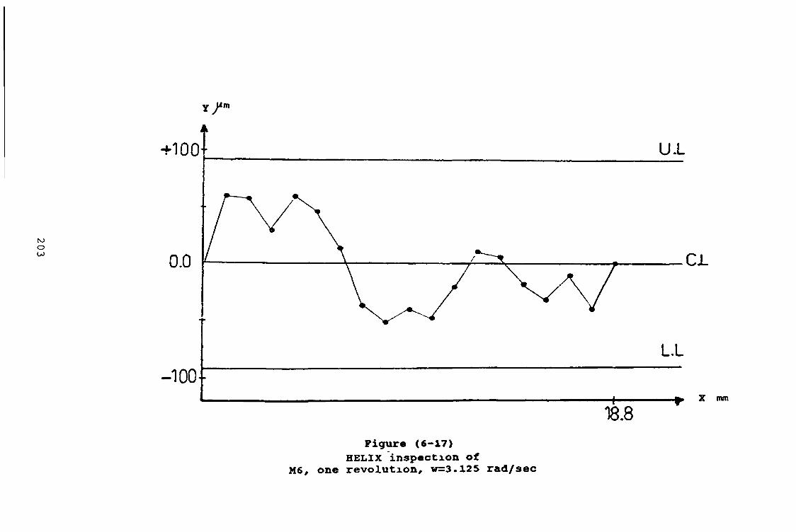
203
Y / m
Figure (6-17)HELIX inspection of
M6, one revolution, v=3.125 rad/sec

this bolt size.Figure (6-18), shows the result due to this velocity. Five revolution were accomplished/ the travelling distance is 125 66 mm, while the total time is 10 sec The maximum deviation due to positive direction is 0 062 mm And it is 0 050 mm m the negative direction It can be seen that after one revolution these maximum deviations are reduced to become 0 040 mm due to the positive direction and 0 045 mm due to the negative direction The actual deviation of this test is 0.112 mm But the comparison with the standard one shows that these deviation is 0 096 mm, which is 0 048 mm for each directionthe result of one revolution due to the same velocity is given in figure (6-19) The maximum deviation in the positive direction is less by 0 008 mm and more by 0 005 mm m the negative directionThus the difference between the maximum values of this test is 0 097 mm, so the comparison with the standard one shows that the actual result is 0.055 mm far from each limit Hence, the accuracy of this result is within +__0 0075 mmIn order to reduce the inspection time, a higher angular velocity 6 25 rad/sec, was used The total time for inspecting five turns is 5 0264 sec, that means one second for each turn The effect of this high velocity can be seen m figure (6-20)The maximum deviation due to the positive direction
0 065 mm, and 0 080 mm, due to the negative direction,
204

205
Y f m
*1004-------
LA'o d m
1 0 0 - .
U L
f- ;a a .
+—^ y H j ~ 1 “
LL
25 50 75 100 125Figure (6-18)i
HE1IX inspection of H8, five reolution, w=2.84 rad/sec
X nun

206
Y / "
Figure (6-19)HILEX inspection of
M8, one revolution, w=2.84 rad/sec
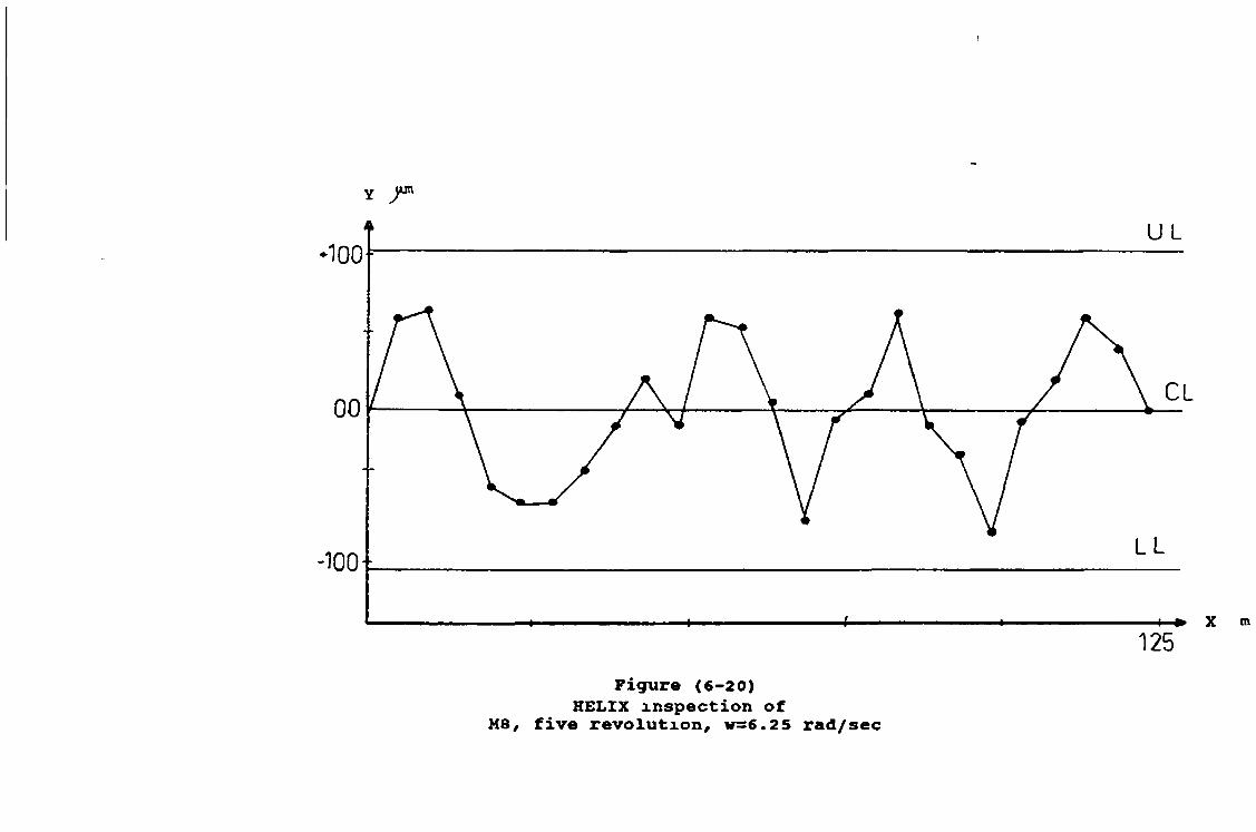
f
Y J“
Figure (6-20)HELIX inspection of
M8, five revolution, w=6.25 rad/sec

the difference is 0.145 mm, the comparison with the standard one shows that this difference is 0 0315 mm The same velocity was used only for one revolution Also, the maximum deviation increases by 0.005 mm, while the other one stays as it was 0.080 mm However, it can be noticed that a few points were m a bad position, these are due to this high velocity, which is forced the stylus to bounce at some points. The bounce value can be found since a comparison is made between these cases and the two previous one This value is 0 048 mm. Also this test is illustrated m figure (6-21)
6-3-3 The result of the bolt sxze M16
Figure (6-22), shows the result due to the slowest angular velocity 1 42 rad/sec The travelling distance 251 32 mm represents the five revolutions which take 22 sec , to be traced by the stylusThe maximum deviation - 0 080 mm can be seen due to the negative direction. While the maximum one due to the positive direction can be seen is 0 092 mm The actual difference between these deviations is 0172 mm. While these deviations are within the theoretical one by 0 06 mm for the positive direction, and 0 072 mm for the negative direction Then the difference between the theoretical and the actual one is 0 132 mm The same velocity was used only for one turn The results shown m
figure (6-23), illustrates that the deviation increases by 0 033 mm due to the positive direction While it
208

20
9
i
25
Figure (6-21)HELIX inspection of
M8, one revolution, v=6.25 rad/sec

210
-150-LL
» x100 250
Figur« («-22)HELIX inspectin of H16
five revolution, v=l.42 rad/sec
mm

HELIX inspection of M16 revolution, v=l.42 rad/sec
F i g u r e ( 6 - 2 3 )

decreases by 0 014 mm in the negative direction.The comparison between the actual difference of this
test and the previous one was increased by 0.019 mm But the difference between the deviation and the limits of the standard one has been affected by a very small value equal to 0 0035 mm. The second velocity was used 2.84 rad/sec Figure (6-24), shows the result of the five revolutions The stylus starts from the maximum points which gives a deviation equal to 0.125 mm due to the positive direction.It can be seen that all the deviation through the first revolution were due to the positive direction However the maximum deviation due to the negative direction is 0 060 mm Thus the total deviation is 0 185 mm, and the actual difference is 0.119 mm The same velocity was used for one revolution only. The results can be seen in figure (6-25) The maximum deviation due to the positive direction is 0 100 mm, and 0 100 mm due to the negative direction The difference between these results and the previous one is 0.015 mm. While the actual difference compared with the theoretical one is 0 052 mm The two previous results were within +_ 0 01 mm
accuracy The total time for five revolution was 12 sec. In order to reduce further more the inspection time, a very high angular velocity of 6 25 rad/sec was used. The total inspection time 5 023 sec for five revolution The result as shown in figure (6-26), has a very small difference compared with the previous one The maximum deviation due to the positive direction is
212/

213
250» X m
F igu re («-24) (H E L IX i n s p e c t i o n o f M l«
f i v e r e v o l u t i o n , w = 2 .8 4 r a d / s e c

Figur« (6-25)HELIX inspection of M16 revolution, v=2 . 8 4 rad/sec
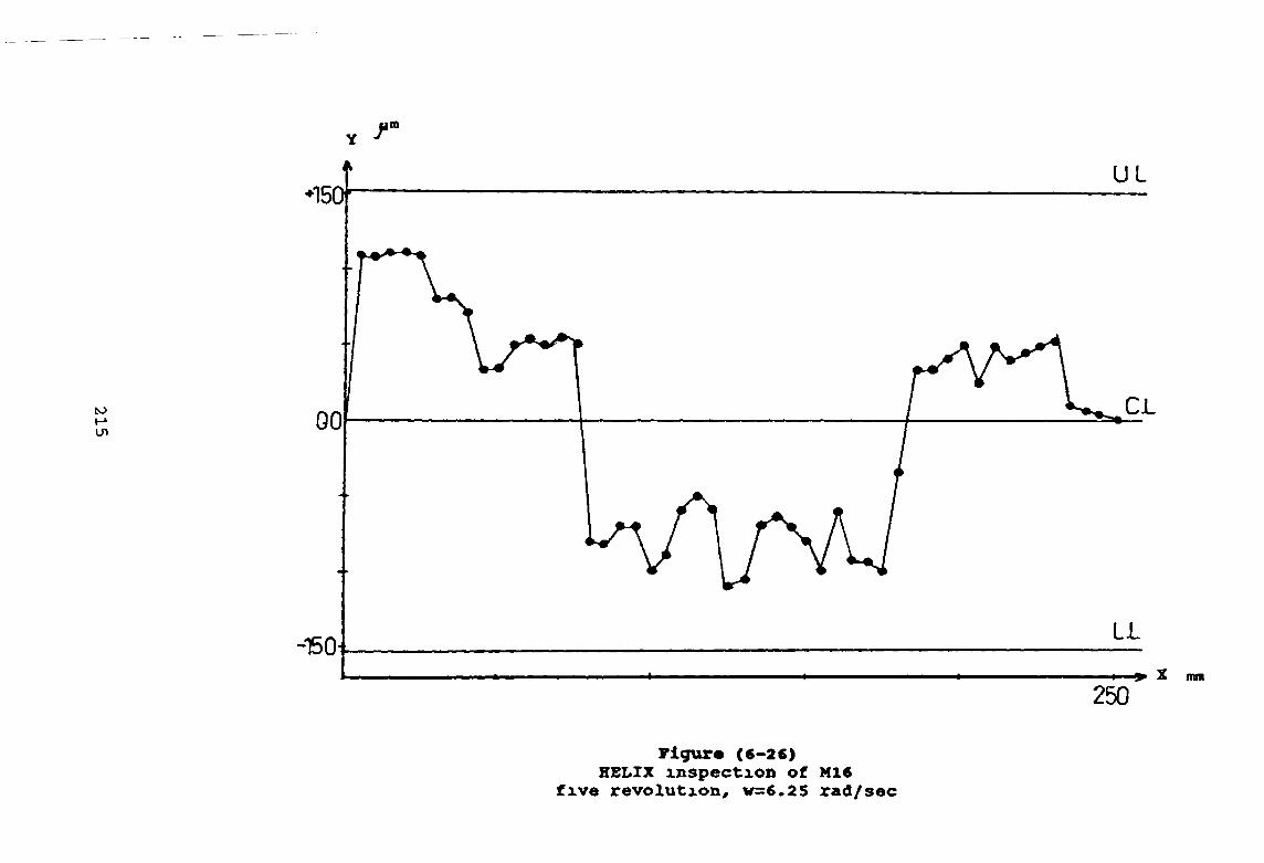
Figur« (6-26)HELIX inspection of M16
five revolution, v=6.25 rad/

0 112 mm and - 0.110 mm due to the negative direction So the difference between the previous one is equal to 0 022 mm It can be seen here, the effects of the high motion which causes the bounce of the stylus at a specified points Also, it can be noticed the strong relation ship among the deviations and the velocities.The last velocity can be adopted for this size of bolt and a correction factor must be added m order to achieve a higher degree of accuracy.
6-3-4 Artificial defects
Two types of defects were made artificially , in order to detect them, using one or more of the previous velocitiesThe first defect was made at the crest of the tooth of
thread, in order to deform its profile form While the second defect was made at the root of the tooth of the thread, m order to deform its helix path
(I)- Form inspection
The artificial defects were made for the bolt size M16, which was manufactured by turning A small part of its crest was removed by milling The slow<velocity 0 83 mm/sec was used in order to detect this defect The actual profile form as shown in figure (6-27), was developed and superimposed on the theoretical one for comparison The comparison shows the disconformity
216

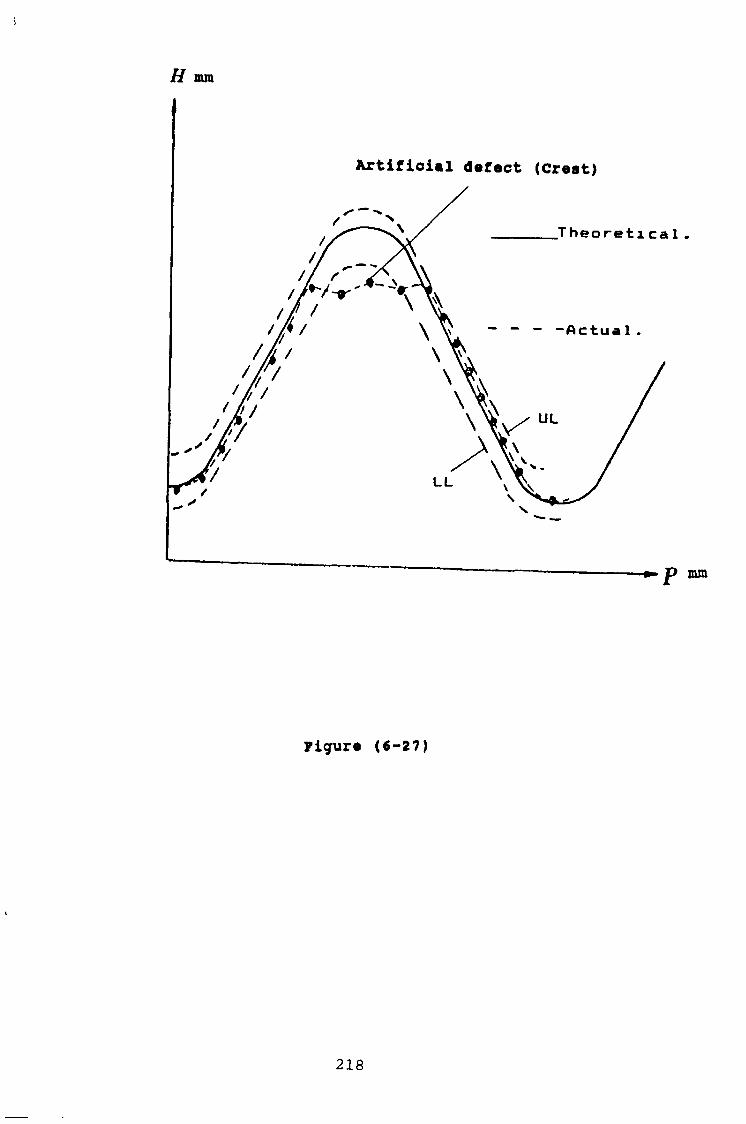
5
H mm
yigure (6-27)
218

between the actual and the theoretical crests.Also, these results were compared with the standard one.The actual difference between the actual and theoretical depth is 0 3269 mmThis difference includes the equivalent size which was removed by milling. In addition, the figure shows two different points at the cutting surface. The first one is 0 86 mm and represents the minimum output at that surface while the second one which represents the maximum is 0 91 mm Thus the test, also, gives some information aboutthe texture of the cutting surface
(2)- Helix path inspection
Another artificial defect was made on the helix path of the same bolt sizeFigure (6-28), illustrates the two results, which were extracted due to two different angular velocities The first test was for the angular velocity 1 42 rad/sec The maximum deviation is out of the upper limit by 0 040 mm The second test was for the angular velocity 2 84 rad/sec The maximum deviation can be seen to be out of the upper limit by 0 045 mm Hence, the actual difference between the result due to the first and second velocities is 0 006 mm This difference refers to the experimental error and the affect of the higher velocity
219

220
Ywn . T
F i g u r « ( 6 - 2 8 )

CHAPTER SEVEN
7 - CO NCLUSION.
7-1 Conclusion
The automatic measuring system, described previously can be used for inspecting external screw threads of size M4 up to M36The operational cycles time is based on the bolt size The measuring principle is based on moving a stylus over the profile form of the thread or along its helix path The operational cycle has a specified consequence for each type of test The displacement, which is converted into an electrical signal interfaced and processed by a personal computer special software was developed, in order to
(a)- Process the signals
(b)- Control the motors
(c)“ Sorting(d)- Computing
(e) - Comparing(f)~ Displaying
(g)~ Plotting
The experiments performed on three different bolt
221

sizes, consequently they were M6, M8 and M16.In order to achieve the minimum inspection time for the form and helix path inspection different ranges of the linear and angular velocities were used The maximum linear velocity of 2 mm/sec was used, m order to perform the profile form inspection for the bolt size Ml6 And the minimum linear velocity was used, also, to perform the profile form inspection 0 5 mm/sec, for the three bolt sizesWhile the minimum angular velocity was used to perform the helix path 1 42 rad/ sec, for the bolt size M16.The minimum range of velocity was located according to special considerations, with regard to the minimum power rate required to drive the motors While the maximum one was controlled considering the bounce affects From the experimental results discussed, it can be concluded that
(1)- The maximum linear velocity which can be used m order to inspect the profile form of the bolt size M6, is 1 25 mm/sec, and the maximum angular velocity which can be used in order to inspect the helix path of the same bolt size is 3 13 rad/sec
(2)- The znaxxmuffl linear velocity which can be used, m order to inspect the bolt size M8, is 1 66 mm/sec and the maximum angular velocity which can be used in order to inspect the helix path of the same bolt size, is 6 25 rad/sec
222

(3)- The maximum linear velocity which can be used, in order to perform the form inspection is 2mm/sec, and the maximum angular velocity in order to perform the helix path inspection of the same bolt size is 6.25 rad/sec.
(4)- The experiment shows that short and very high velocity mean less accuracy vice versa.
(5)- One of the effects of the bounce decreases the point of accuracy
(6)- The stylus move smoothly due to the very slow velocity
(7)- A high degree of accuracy of 0 009 mm was achieved
(8)- The resolution of the system is 0 000002 mm(9)~ The movement of the stylus follows the
increase/decrease due to the rate of change of the stylus speed at the root and crest area of the tooth And this explains, why the stylus bounce at the root or crests due to the very high velocity
(10)“ The xainimum increment which was achieved is0 0491 mm and the minimum difference was 0 0001 mm While the maximum increment is 0.2027 mm and the maximum difference is 0 004 mm
This system, with some modification can be used for inspecting other types of objects Also it can be used for testing the surface texture
7-2 Recommendation for further work
223
In order to improve the operational cycles of this automatic inspection system, an automatic feeding process can be added to one sideWhile, another automatic removing process can be added to the other side, thus, the feeding, inspecting, removing are accomplished consequently.Also, this system with a suitable modifying, can be built with the machine which produces the external screw threads, and screw components.
224

REFERNCES
[1]
[2]
[3]
[4]
[5]
[ 6 ]
[7]
[8]
[9]
[10]
Sydenham P . H , " Handbook of measurement Science ”, 1982, John Wiley & sons Ltd.Harris Horman C , Hemmering Edwin M , "Introductory Applied Physics ", 1980 , McGRAW-HILL, inc , USABoston 0 W ," Metal processing " second edition, New York John Wiley&Sons, Inc, 1967 Hicks, E Philip ," Introduction to Industrial Engineering and Management Science ", 1977, McGraw-Hill incScarr A J T , ” Metrology and Precision Engineering ", 1967 , McGraw-Hill, publishing company Limited BritainLindberg,Roya , "Processes and Materials of Manufacture ", 1983, by Allyn and Bacon, inc , USADeGramo E Paul , Black. J Temple., Kohser Ronald , " Materials and Processes in Manufacturing ", MacMillan company, 1984, New York Groover Mikell P, " Automation Production and Computer Integrated Manufacturing ", 1987, by Prentice-Hall incLissaman and S J Martin , 11 Principles of Engineering Production ", 1982, by MacMillan, India Ltd, BangalorJornes J S Quality Through Measurement ",

[12]
[13]
[14]
[15]
[16]
[17]
[11]
Proceeding of the 7th Conf. on Automated Inspection and Product Control, 26-28 march, 1985, Birmingham OK.Bentley John P. " Principle of Measurement Systems.", second edition , John Wiley 6 sons, inc New YorkReid G T , Mai shall S J , Rixon R.C and Stewart H , " A laser Scanning Camera for Range Aquistion, National Engineering Laboratory, East Kilbride , Glasgow G75 OQU UK , 1988, IOP Published LtdAllocca John, Stuart Allen , " Transducers Theory & Application ", 1983 , McGRAW-Hill , m e , USA Jarvis R A , 1983 ,IEEE Trans , " Pattern Anal. Machine Intell ", PAMI-5 , 122-39 Smith Ernest ,"Principle of Industrial Measurement for Control Application ", Instrument Society of America, 1984Doemens, G , " Application of Sensors in The production and Quality Control of Micrelectronic Devices and Electromechanical Component ", PP 187-197 , 5th International Conf on Automated Inspection and Product Control , 1980,
Stuttgart, Germany Albrecht m , Jacoby.A and A Scens, URW Unternehmensberatung karow Rubow Weber GmbH, AND 2 P Sondermann, Volkswaguenwerk A G , " Automated Viusual Inspection for Component Manufacture and Assembly in the Automated Industry ", Proceedings

of the 5th International conference on Automated Inspection and product control 12 1A Arbeitstagung, Stuttgart , Germany 24-26 June 1980
[18] Bretschi J and M Konig , Fraunhofer-Instute Fur Informations -und Datenverarbeitung (11TB) , Karlsuhe , " Optical and Accoustic Sensor Systems
)for Patern Recognition tasks" , Proceedings of the 5th International conference on Automated Inspection and Product Control 12 1A Arbeitstagung, Stuttgart, Germany , 24-26 June 1980
[19] Skaggs Frank L , " Vision- based Parts Measurement System ", Proceedings of the 3rd International Conference on Robot Vision Sensory Controls, 6-10 November 1983 , Combndge , Massachusetts , USA
[20] Porter G Be," A non- Contact Profile Sensing Systemfor Visual Inspection ", PP720-730 , Proc 6th int Conf on Pattern Recognition , 1982 , Munich, Germany, NewYork , UAS , isss
[21] Jentner W schidberger. E , " Solving Problem ofIndustrial Quality Control by Means of Image Processing System ", PP367-378 , 2nd Int conf on
Robot Vision and Sensory Control System, Stuttgart, 1982
[22] Warnecke H-j and Abrens-u., " Loading and Unloading of Pallets Using Sensor-Assisted Industrial Robots ", Frunbofer-Instute for
Manufacturing Engineering and Automatic Nobestr 12,700, Stuttgart 80, Fedral Republic of

[23]
[24]
[25]
[26]
[27]
[28]
[29]
Germany., copy right IFAC Information control problem in manufacturing technology, Maryland USA 1982Koenlhgsberg. W.D.," Non-Contact Distance Sensor Techology.", Proceedings of the 3rd Internaional Conference on Robot Vision and Sensory Controls. 6- 10 November 1983 , Cambridge , Massachusetts USA. Nawrath R F , Heinrich K, Unshexd Wand Stoll.d, " Visual Inspection and Quality Control by TAS ", Proceedings of the 5th Internaional Conference on Automated Inspection and Product Control , 12-1A Arbeitstagung, Stuttgart, Germany 24-26 June 1980 B S I , "Screw Threads, Manual of British Standards m Engineering Metrology ", British Standard institution in association with Hutchinson , ISBN 0091519314 , Printed in Great Britain J Galyer & C Shotbolt ," Acassel Technical Book, Meterology for Engineering ", 1980 London , ISBN 0-304-30612-6.Drewery J W , "A flexible Approach to Computer Aided Quality Management , " Proceedings of th 7th Internaional Conference on Automated Inspection and Product Control, 26-28 March 1985, Birmingham UK. Warnecke H J and Kampa H , " Flexible Production System in the Fedral Republic of Germany IFAC Information Control Problems in Manufacturing Technology, Mary land USA 1982 Poulter K F , " Computer Aided Dimensional Engineering Metrology, Advantages and

Disadvantages ", Proceedings of the 7th International Conference on Automated Inspection and Product Control, 26-28 March 1985, Birmingham , UK
[30] Todd J D , 11 Advanced Vision Systems for Computer- Integrated Manufacture ," Part I , Automtion Division, National Engineering Laboratory East Kilbride, Glasgow G75 OQU, UK, Computer Integ Manuf System 1988 Vol 1 No3, PP143-154
[31] Todd J D and Morrison A J ," A verstaile Develpoment facility for Automtic Visual Inspection Application ", Automatic Devision, National Engineering Laboratory, East Kilnde Glasgow, UK , Birmingham 19-21 sept 1988 , Kogan page Ltd, London
[32] Batchelor B G,Williams G A.," Defect Detection on the Internal Surfaces of Hydraulics Cylinders for Motor Vehicales "., Proceedings SPIE Conference on Imaging Applications for Automated Industrial Inspection and Assembly, 1979 Bellingham WA ,USA
[33] Schmidberger E,Melchior K, Rueff M ," Electro-optical in-line Quality Control in IndustrialProduction ," 3rd International Conference on Robot Vision and Sensory Control, Combndge 1983 pub USA
[34] Smolka Francisco m and Cuadell Thornes P " Anon-Contact Method for S urface Profile Measurement andAngular Deffelection Monitoring Using A scanning Laser Beam ," Physics Department, University of

Arizona, Tuscon, Arizona 85721, SPIE Vol.153 Advances in Optical Metrology 1978.
[35] Maruyama Kazuo, Ozura Nobuhiko and Totsuka shinichi., " Development of Automatic Measuring Machine for Bad Errors in the Threaded Cutting Tools ," Bull .Japan. Soc of Proc Engg., Vol 20 No 31 sept 1986.
[36] Batchelor .B 6 , " Preliminary Role on Automatic Inspection of Male Screw Threads " , Proc 3rd Int. Conf. on Automated Inspection and Product Control 1987 IFS Ltd, Bedford UK pp 139-159
[37] Haraud R Charraas J P , " Automatic Inspection and Orientation of External Screws , 11 Laboratoire d' Automatique de Gremoble, p 46-384002 ST Martin D'heres-France 1980 IEEE
[38] Batchelor B G ," Proposal for the Automatic Visual Inspection of Femal Screw Threads ", PP 157-176 Proc , 3rd Int , Conf , on Automated Inspection and Product Contact , 1987
[39] Kampa Hand Sscwertz ," Measurement of Internal Threads in A multi-Coordinate Measurement Devices , " Proceedings of the 5th International Conference Automated Inspection , and Product Control , 12. 1A Arbeitstagung , Stuttgart, Germany, 24-26 June 1980
[40] Schauerte Meinolf B , " Flexible 'Mauser' Multi- Point Measuring Centers for API and Buttress Oil Pipe Threads " 3rd Int Conf. on Steel Rolling Tech of pipe and Tube and Their Application 2-6

[41]
[42]
[43]
[44]
[45][46][47][48][49][50][51]
[52]
[53]
[54]
September 1985 Tokoyo , Japan.Sullnvan p j / 11 Error Correction in 3D Surface Topography Measurement ", Department of Manufacturing Systems the University of Birmingham
Edgbaston, Birmingham BI52TT.Amstead .B h, Ostwald Philip F, Begeman Myronl , " Manufacturing Processes ", 1979, by John Hiley & SonsBS 84 1956 , " British Standard Specification forParallel Screw Threads of Whitworth Form , " National Physical Laboratory ," Notes on Applied Science No 1, Gauging and Measuring Screw Threads ” , Department of Scientific and Industrial Research , 1958 , London BS 3643 " ISO Metric Screw Threads "BS 4827 " ISO Miniature ThreadsBS 4846 " ISO Trapezoidal Threads".BS 21 " Pipe Threads for Tubes and Fittings "BS 84 . M Whitworth Form Threads "BS 93 : " British Association 9BA)Threads ".Ostwasky o, "Engineering Drawing for Technicians " , 1981, Edward Arnold (publisher) Ltd BS 3643 , " ISO Metric Screw Threads " ,Hand book 1981BS 3643 , " Specification for ISO Metric Screw Threads" , Part 1, Principle and Basic data ,1981.Galyer J F W and Shotbolt R , " Meterology for Engineers" , Cassel , 1980 London
[55]
[56]
[57]
[58]
[59]
[60]
[61]
[62]
[63]
[64]
[65]
[66]
Halliday David , Resnick Robert, Edwards W Farrell and Merrill John " Fundamentals of Physics n,John Wiley 6 Sons, New York.Stanley Robert .W., 11 Study Guide for Miller's, Colloge Physical 1982, by Harcourt Brace Javanovich IncSydenham, P H " Measuring Instruments Tools of Knowledge & Control ", 1980, casebound (ISBN 0- 906048-19-2, HTOO 1, Peregrnus England , Institution of Electrical Engineers Renishaw, "CMM Styli printed in England Ref H/1000/3065/01/A, 1988 Renishaw.Parker , " Digiplan , Programmable Motion System " , 1989 Parker Hannifin Corporation Barney George c "Intelligent Instrumentation Micoprocessor Applicatioins Measurement amd Control 1985 by Prentic Hall International (UK), Ltd Kuo Benjamin C "Automatic Control System 2 , Englewood Cliffs, Nj, Prentice-Hall, c 1982 J A Haslam.,G.R Summers , D.Williams ," Engineering Instrumentation and Control" , by Edward Arnold Cnpps Martin " Computer Interfacing " , 1989, first published m UK , LondonDAC-02 Manual , MetrByte corporation, 440 Myles Standish Boulevard , Tautton Mass 02780 , USA , 1984DASH-8 Manual MetrByte corporation, 254 Tosca Drive, Stoughton, mass 02072 USA. 1990 RDP Electronics Ltd "Technical manual " ,

Transducer amplifier S7M, Grovr street heath Town Wolverhampton WVIO OPY, 1990, UK

APPENDIX (A3-1)
TABLES SHOWING VIRTUAL DIFFERENCE IN DIAMETER CORRESPONDING TO ERRORS IN PITCH AND ANGLE
TABLE 15VIRTUAL DIFFERENCE IN EFFECTIVE DIAMETER CORRESPONDING
TO MEASURED ERRORS IN PITCH
Corresponding Virtual Difference in Effective Diameter
Error i n -------------------------------------------------------------------------------------Pitch
Unified, Metric and
B S C Threads
WhitworthThreads B A Thread* Acme Threads
in in in in in0*00005 000009 000010 000011 000019
00001 000017 0 00019 0 000 23 0 000 39
000015 0 000 26 0 00029 0 000 34 0 000 58
00002 0 000 35 0 000 38 000045 0 000 77
0 000 25 000043 0 00048 0000 57 0 000 97
00003 000052 0000 58 0 00068 0001 16
0000 35 0 00061 000067 0000 79 000135
0 0004 0 000 69 0000 77 0 000 91 0001 55
000045 0 000 78 000086 000102 0001 74
00005 0 000 86 0 00096 0 001 14 0 001 93
0 000 55 0 00095 0 00106 0 001 25 0 00213
00006 000104 0 001 15 0001 36 0 002 32
000065 0001 12 0001 25 0-00147 0 002 51
00007 000121 0 001 34 0 001 59 0 002 71
0 000 75 j 0 001 30 0 00! 44 0 001 70 0 002 90
00008 ! 0001 38 0 001 54 0001 81 0 003 09
000085 0 001 47 0 001 63 0 00193 0 003 29
0 0009 0 001 56 0 00173 | 0-002 05 0 003 48
0 000 95 0001 64 OOOI82 0 002 16 0 003 67
0 0010 0 001 73 ' aoo i92 0 002 27 0 003 87
Wwt —The Difference is to be lakvn as + for external threads and — for internal threads

APPENDIX A(4-l)
I-METRIC
-General:J = D4L/8
-Acceleration torque (speed o to w ):Ta =3w/t(JL+ Js+ Jm)/e x 10
-Equivalent inertia of load:JL = Wl p2 / 4000
- Friction torque:Tf = Fp/ 644e
-For a sliding system, frictional force*F —US• WL i
- Total motor torque*T =Ta + T f
- Acc. torque (speed o to W):Ta ss 3.J.W/t x 10 -6
Where:J=moment of inertia , Kg-cm2. D=diameter cmL=length (or thickness),cm.W=weight ,Kg.Ta=acceleration torque, Nm. w= max. speed, full steps/sec t=time to reach w,secs
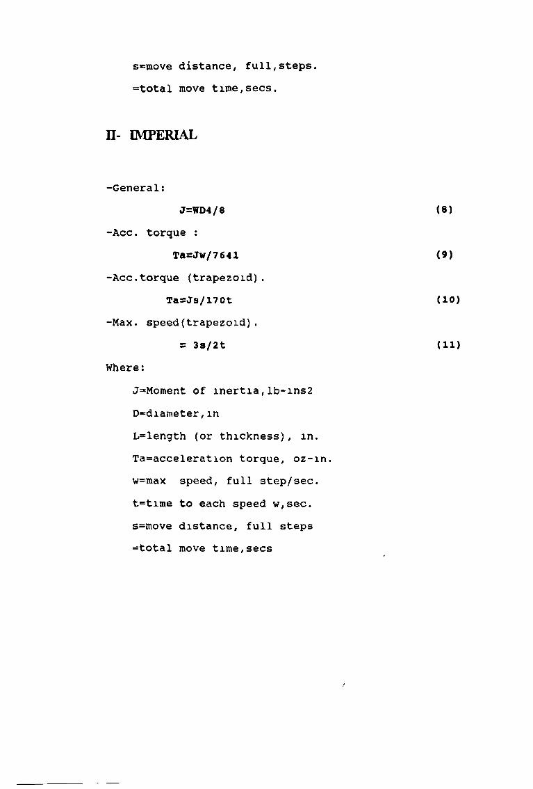
s=move distance, full,steps. =total move time,secs.
II- IMPERIAL
-General:J=WD4/8 ( 8 )
-Acc. torque :Ta=Jw/7641 (9)
-Acc.torque (trapezoid).
-Max. speed(trapezoid).
J=Moment of inertia,lb-ins2 D=diameter,inL=length (or thickness), in. Ta=acceleration torque, oz-in. w=max speed, full step/sec. t=time to each speed w,sec. s=move distance, full steps =total move time,secs
Tü=Js/170t (10)
= 3s/2t ( 11 )
Where:
F

APPENDIX (A4-2)
Technical specification The " medium duty M motor
Type 5r.pm at 12 vd.c, 8Max. power (w) 4Max . torque (m N m)
continuous 600peak 1800
Gear box reduction 500:1Norn. voltage (v d. c. ) 12Starting voltage m,n
no load (v.d.c) 0.15Nom no load current
(in A) 15Max cot operating
current (m A) 493Terminal resistance (52) 10Max rotortemperature (c) 85W e i g h t ( g ) 2 6 2

APPENDIX (A4-3)
- Technicals pecification of the ,f heavy duty 11 motor.
Type 2rpm at 12 v d.c 20Max. power (W mech ) 16Max.torque (m N m)
continuous 1200peak 4000
Gearbox reduction 130:1Nom. voltage (v d.c) 12starting voltage, min no load 3vNorn, no load current (m A) 590Max. continuous operating current (m A) 2800 Terminal resistance (o2) 2Max. rotor temperature 130 cW e i g h t ( g ) 6 7 0

APPENDIX (A4-4)
Technical specification of the LVDT
type of (GT x 2500),
- Linear stork . . . . . .-O/P voltage ............. ....-Current LVDT ......................-Linearity .........................-Operation temperature ............-Weight (less cable).................-Spring force .......................Figure (4-13), illustrates this sensor
160 m v/v.160 m A (6 m A).
0 25% of fullstorke. -40 c to+ to 100 c.
18 g m 118 g m

APPENDIX (A4-5)
The technical specification of the Digital to Analog D/A
converter type DAC-02
Power suppliers:+5V supply 75 m A type,100 m A Max.-5V supply* not used+12V supply: 15 m A typ. 1 25 m A max.“12V supply: 25 m A type,35 m A max.
Total power dissipation typical.Output ranges Channels:2I/o address :DIP switch selected on any 8 bit boundary.Resolution: 12 bits (1 part in 4095)Relative accuracy: 1/2 LSB (0.01%) max.Differential linearity: 1/2 LSB max.Fixed reference ranges. 0 to + 5V (unipolar)
0 to + 10V (unipolar)+/-5 V (bipolar)+/-10 V (bipolar)4-20 m A current loap.

variable reference ingest: +/- 10 V (2 or 4 quadrant) reference input resistance : 7 known mm, 11 kohm type, 20 kohm max.Voltage output impedance:<0.1 ohm max. Voltage output drive current: +/~5 m A min.4-20 m A compliance : 8- 36 V (for current loop) EnvironmentalTemperature coefficient: +/- 25 ppM / deg.c. (with reference)
of gain: +/- 5 ppM / deg.c. (external ref.)Zero drift: 0-70 deg c.Storage temperature :- 55 to + 125 deg.c.Humidity :0- 95% non- condensing Weight- 4 02 (120 g).

APPENDIX (A4-6)
The technical specification of the ANALOG TO DIGITAL (A/D)
converter type DASH-8
-Resolution -Full scale -Input current-Sample and hold acquisition time -Reference voltage -Reference current -Digital output sink current -Digital output source current digital input high voltage -Digital input low voltage
12 bits. (2.44 m v/ bit) +/-5 volts.100 n A max at 25 degree.c
15 us for 0.01% error +10.0 v + /-0.1 v +/-2m A8 . 0 m A (Lo =.5 v)- 0 4 m A (hi= 2 7 v)2.0 v min.0 . 8 v max.

APPENDIX (A4-7)
The technical Specification of transducer amplifier
type S7M.
-Supply: 120 or a c. +/- 15% 50/60H2 at 2 5 v A -Fuse: 200 mA A-5-Excitation(note 1) • 5 v rim.5. 5 KHz sinusoidal ( lKHz-lOKHz to order ).100m A maxExcitation Tempo *+/-0 003%c. typicalAmplifier outputl: +1/- 10 v 5 m A max (short-circuit proof) output2*see options B and C specification below Amplifier gain: x 03 to x 200 m 8 ranges Linearity : +/- 0.1% of full scale max.Demodulator : synchronous.-zero tempo: +/- 0.002% f.5/c. typical.-Gam tempo. +/-0.002% f.5/.c, typical.-Bandwidth, flat to 500 h2.-Output noise : 5 m v p.p typical(pK-pK)-Input option z : 10 ohm differential -Zero adjustment range . +/- 10 v minimum Temperature range .10 to + 50cDimensions (excluding cable glands). 8 7 x 4 75 x 3.25 in (220x 120 x 81 mm)Weight : 3 3/4 Lb, 1 7 kg

-Physical protection .1 p 65 specification-Gland cable diameter (notes2): 0.08 to 0.2 m (2 to 5 mm) [63]