quality control of nuclear medicine ... - eanm.org · domains and therefore require the necessary...
TRANSCRIPT
QUALITY CONTROL QUALITY CONTROL QUALITY CONTROL QUALITY CONTROL QUALITY CONTROL QUALITY CONTROL QUALITY CONTROL QUALITY CONTROL QUALITY CONTROL QUALITY CONTROL QUALITY CONTROL QUALITY CONTROL QUALITY CONTROL QUALITY CONTROL QUALITY CONTROL QUALITY CONTROL QUALITY CONTROL QUALITY CONTROL QUALITY CONTROL QUALITY CONTROL QUALITY CONTROL QUALITY CONTROL QUALITY CONTROL QUALITY CONTROL QUALITY CONTROL QUALITY CONTROL QUALITY CONTROL QUALITY CONTROL QUALITY CONTROL QUALITY CONTROL QUALITY CONTROL QUALITY CONTROL QUALITY CONTROL OF NUCLEAR OF NUCLEAR OF NUCLEAR OF NUCLEAR OF NUCLEAR OF NUCLEAR OF NUCLEAR OF NUCLEAR OF NUCLEAR OF NUCLEAR OF NUCLEAR OF NUCLEAR OF NUCLEAR OF NUCLEAR OF NUCLEAR OF NUCLEAR OF NUCLEAR OF NUCLEAR OF NUCLEAR OF NUCLEAR OF NUCLEAR OF NUCLEAR OF NUCLEAR OF NUCLEAR OF NUCLEAR OF NUCLEAR OF NUCLEAR OF NUCLEAR OF NUCLEAR OF NUCLEAR OF NUCLEAR OF NUCLEAR OF NUCLEAR MEDICINE MEDICINE MEDICINE MEDICINE MEDICINE MEDICINE MEDICINE MEDICINE MEDICINE MEDICINE MEDICINE MEDICINE MEDICINE MEDICINE MEDICINE MEDICINE MEDICINE MEDICINE MEDICINE MEDICINE MEDICINE MEDICINE INSTRUMENTATION INSTRUMENTATION INSTRUMENTATION INSTRUMENTATION INSTRUMENTATION INSTRUMENTATION INSTRUMENTATION INSTRUMENTATION INSTRUMENTATION INSTRUMENTATION INSTRUMENTATION INSTRUMENTATION INSTRUMENTATION INSTRUMENTATION INSTRUMENTATION INSTRUMENTATION INSTRUMENTATION INSTRUMENTATION INSTRUMENTATION INSTRUMENTATION INSTRUMENTATION INSTRUMENTATION INSTRUMENTATION INSTRUMENTATION INSTRUMENTATION INSTRUMENTATION INSTRUMENTATION INSTRUMENTATION INSTRUMENTATION INSTRUMENTATION INSTRUMENTATION INSTRUMENTATION INSTRUMENTATION INSTRUMENTATION INSTRUMENTATION INSTRUMENTATION AND PROTOCOL AND PROTOCOL AND PROTOCOL AND PROTOCOL AND PROTOCOL AND PROTOCOL AND PROTOCOL AND PROTOCOL AND PROTOCOL AND PROTOCOL AND PROTOCOL AND PROTOCOL AND PROTOCOL AND PROTOCOL AND PROTOCOL AND PROTOCOL STANDARDISATION
EANM TECHNOLOGISTS GUIDE
Produced with the kind support of


Foreword 4 Pedro Fragoso Costa
Introduction 6 Sebastijan Rep
Chapter 1 Principles of quality control and quality assurance 9 Goran Vuleta
Chapter 2 Internal and external auditing of quality 17 management systems: the approach of the International Atomic Energy Agency Maurizio Dondi, Thomas Pascual and Diana Paez
Chapter 3 Planar camera and SPECT system quality control 29 Mario Medvedec
Chapter 4 PET system quality control 43 Claudiu Peștean
Chapter 5 CT system quality control 53 Urban Zdešar and Dean Pekarovič
Chapter 6 Optimisation of SPECT and SPECT/CT – 67 acquisition and reconstruction Maximilien Vermandel and Hélène Lahousse
Chapter 7 Optimisation of PET/CT — acquisition and reconstruction* 85 Leesa Ross and Dusty York
Chapter 8 Accreditation for clinical trials: the EANM EARL Project 103 Giorgio Testanera and Michel de Groot
Chapter 9 Radionuclide calibrator 117 Aljaz Socan
Chapter 10 Quality control of nuclear medicine instrumentation 131 and protocol standardisation Kristof Baete
Chapter 11 Well counters 141 Petra Kolenc Peitl and Marko Krošelj
Chapter 12 Radiation Protection Measurement Equipment 153 Søren Holm
3QUALIT Y CONTROL OF NUCLEAR MEDICINE INSTRUMENTATION AND PROTOCOL STANDARDISATION
TABLE OFCONTENTS
*Articles were written with the kind support of and in cooperation with the

4 QUALIT Y CONTROL OF NUCLEAR MEDICINE INSTRUMENTATION AND PROTOCOL STANDARDISATION
In the ever-evolving field of nuclear medicine (NM), technologists are at the intersection between the clinical, research and academic domains, embodying the bridge towards patients. Quality has become an unavoidable word in NM practice. In the last two decades, NM has earned an established place in various clinical areas on the basis of the advances in respect of evidence-based practice and high-level research. Naturally, nuclear medicine technologists (NMTs) have been and will be involved in the clinical, research and academic domains and therefore require the necessary tools to carry out their tasks in compliance with best practice. This is the main motivation for choosing Quality Control of Nuclear Medicine Instrumentation and Protocol Standardisation as the topic for our annual Technologist’s Guide.
FOREWORD
Foreword

5QUALIT Y CONTROL OF NUCLEAR MEDICINE INSTRUMENTATION AND PROTOCOL STANDARDISATION
FOREWORD
The Technologist’s Guide is an annual pub-lication envisioned and edited by mem-bers of the EANM Technologist Committee (EANM-TC). It is one of the many EANM educational initiatives and has the aim of completing the training of NMTs and en-couraging scientific exchange within the NM community. The Technologist’s Guide was and continues to be a reference for educational standards inside and outside Europe.
As the topic of this guide encompasses a very broad range of applications, we de-cided to divide the book into three parts. The first part focusses on the principles of quality and standardisation, an under-standing of which is needed in order to completely grasp the more practically oriented parts 2 and 3, which are devoted to imaging procedures and non-imaging instrumentation, respectively.
This book is a multidisciplinary effort in-volving different professional groups that
work to achieve the same outcome in the domain of NM: maintenance of the best practice standards to ensure opti-mal implementation of patient-focussed diagnostic and therapeutic procedures. I am extremely grateful to all authors for sharing their expertise, which has been fundamental to the successful completion of this Technologist’s Guide. I would like to thank the EANM Physics Committee, the SNMMI-TS (Society of Nuclear Medicine and Molecular Imaging Technologist Sec-tion) and the International Atomic Energy Agency (IAEA) for their help in ensuring the outstanding quality of this book. I am very much indebted to the EANM-TC edi-torial and language revision group for their dedication in reviewing and editing this guide. Finally, thanks are due to the EANM Board, the EANM Technologist Committee and all of those involved in the Technolo-gist’s Guide project.
Pedro Fragoso CostaChair, EANM Technologist Committee

6 QUALIT Y CONTROL OF NUCLEAR MEDICINE INSTRUMENTATION AND PROTOCOL STANDARDISATION
INTRODUCTION
Technologists are members of the team required for implementation of diagnostic imaging in nuclear medicine (NM). In many hospitals, the technologists are responsible for the quality assurance (QA) duties. The development of hybrid imaging has increased further the need for strict implementation of quality control (QC) and also rendered QC more demanding. These new guidelines from the EANM Technologist Committee address the tasks necessary for the smooth implementation of QC in NM departments.
Introduction

7QUALIT Y CONTROL OF NUCLEAR MEDICINE INSTRUMENTATION AND PROTOCOL STANDARDISATION
INTRODUCTION
Quality control is required to ensure that NM equipment is functioning properly and constitutes an important part of the quality management in an NM depart-ment. The described QC tests are designed to detect problems before they affect clinical patient studies. They are intended to provide a full evaluation of equipment performance and to ensure that equip-ment is performing properly after service or adjustment.
Quality control is important due to the need to optimise patient exposure and image quality during NM imaging exam-inations. The image quality is dependent upon the data acquisition parameters, which must be adapted to the detector system and also the reconstruction algo-rithm, on the basis of which the acquisi-tion time can be shortened or the adminis-tered activity of the radiopharmaceuticals can be decreased.
These guidelines cover the principles of QC and QA, including QC and improve-ment of imaging protocols for both im-aging and non-imaging instrumentation. The first part describes separately the
QC tests for conventional NM modalities such as planar gamma camera imaging, SPECT and PET and also for hybrid meth-ods such as SPECT/CT and PET/CT. An individual chapter is devoted to CT sys-tem QC as this constitutes an important element in the optimisation of acquisition protocols. The second part covers image optimisation protocols for SPECT/CT and PET/CT modalities and accreditation for clinical trials. The third part describes QC of non-imaging instrumentation, such as radionuclide dose calibrators, intraopera-tive probes, body uptake probes and well counters.
This overview of QC and protocol opti-misation will be a valuable tool for tech-nologists and all clinical staff involved in this particular field.
In the name of the EANM Technologist Committee, I would like to thank all the au-thors who have taken the time to prepare and write the chapters and to all the edi-tors who have helped to create this book.
Sebastijan Repon behalf of the editors


1PRINCIPLES OF QUALIT Y CONTROL AND QUALIT Y ASSUR ANCE
by Goran Vuleta
QU
ALIT
Y C
ON
TR
OL O
F NU
CLE
AR
ME
DIC
INE
INS
TR
UM
EN
TAT
ION
AN
D P
RO
TOC
OL S
TAN
DA
RD
ISA
TIO
N

10 QUALIT Y CONTROL OF NUCLEAR MEDICINE INSTRUMENTATION AND PROTOCOL STANDARDISATION
CHAPTER 1
PR
INC
IPLES O
F QU
ALIT
Y C
ON
TRO
L A
ND
QU
ALIT
Y A
SSUR
AN
CE
Quality is an important factor for any product or process in medicine. It is widely recognised that the attainment of high standards of efficiency and reliability in the practice of nuclear medicine, as in other specialties based on advanced technology, requires an appropriate quality assurance programme[1].
In order to maintain or improve the quali-ty of equipment and processes, careful at-tention must be paid to the two standard concepts of quality assurance and quality control:
» Assurance: the act of giving confidence. Quality assurance (QA) is a way of pre-venting mistakes or failure in products. QA is a process-focussed concept. It is a systematic process implemented within a quality system (Table 1).
» Control: the act of guiding a process. Quality control (QC) is a process involv-ing the inspection of equipment to en-sure that the quality of all aspects is sat-
isfactory. QC is a product-focussed con-cept. It comprises a set of procedures intended to ensure that a manufactured product or performed service adheres to a defined set of performance criteria (Table 1).
Hence, QA in nuclear medicine should cover all aspects of clinical practice. Spe-cifically, QC is necessary in the submission of requests for procedures; the prepa-ration and dispensing of radiopharma-ceuticals; the protection of patients, staff and the general public against radiation hazards and accidents caused by faulty
Quality assurance Quality control
Activities Set of activities for ensuring quality in processes Set of activities for ensuring quality in products
Aim To prevent defects To identify (and correct) defects
Process Proactive Reactive
Means of
achievement
Planned and systematic activities, including
documentation
Activities or techniques to achieve and maintain
the product quality, process and service
Responsible
persons
Everyone involved in the process Specific team that
tests the product
Tool QA is a managerial tool QC is a corrective tool
Table 1: Quality assurance versus quality control
11
CHAPTER 1
QUALIT Y CONTROL OF NUCLEAR MEDICINE INSTRUMENTATION AND PROTOCOL STANDARDISATION
equipment; the scheduling of patients; the setting-up, use and maintenance of electronic instruments; the methodology of the actual procedures; the analysis and interpretation of data; the reporting of re-sults and, finally, the keeping of records[1].
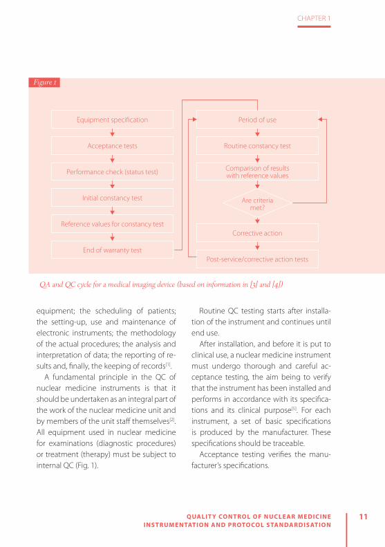
A fundamental principle in the QC of nuclear medicine instruments is that it should be undertaken as an integral part of the work of the nuclear medicine unit and by members of the unit staff themselves[2]. All equipment used in nuclear medicine for examinations (diagnostic procedures) or treatment (therapy) must be subject to internal QC (Fig. 1).
Routine QC testing starts after installa-tion of the instrument and continues until end use.
After installation, and before it is put to clinical use, a nuclear medicine instrument must undergo thorough and careful ac-ceptance testing, the aim being to verify that the instrument has been installed and performs in accordance with its specifica-tions and its clinical purpose[5]. For each instrument, a set of basic specifications is produced by the manufacturer. These specifications should be traceable.
Acceptance testing verifies the manu-facturer’s specifications.
Equipment specification
Acceptance tests
Performance check (status test)
Initial constancy test
Reference values for constancy test
End of warranty test
Are criteria met?
Corrective action
Post-service/corrective action tests
Period of use
Routine constancy test
Comparison of results with reference values
QA and QC cycle for a medical imaging device (based on information in [3] and [4])
Figure 1

12 QUALIT Y CONTROL OF NUCLEAR MEDICINE INSTRUMENTATION AND PROTOCOL STANDARDISATION
CHAPTER 1
PR
INC
IPLES O
F QU
ALIT
Y C
ON
TRO
L A
ND
QU
ALIT
Y A
SSUR
AN
CE
At the same time, reference tests should be undertaken. These reflect operating conditions under clinical conditions and provide results against which to test the ongoing performance of the equipment by routine testing at weekly, monthly, quarterly or yearly intervals.
A basic level of routine QC is required to ensure that nuclear medicine equipment is functioning properly. Routine QC tests are intended to detect problems before they impact on clinical patient studies (Fig. 2). Once the instrument has been installed and accepted for clinical use on the basis of the acceptance testing re-sults, its performance needs to be tested routinely with simple QC procedures that are sensitive to changes in performance. Tests must be performed by appropriate-ly qualified and trained staff, and detailed local operating procedures should be written for this routine work. All test re-sults must be recorded and monitored for variations, and appropriate actions taken when changes are observed. The QC tests are an important part of the routine work, and sufficient equipment time and staff time must be allocated for routine QC[5]. All test results must be recorded and monitored.
The QC of each instrument should have as its starting point the selection and pro-curement of the instrument itself, because instruments may differ in their characteris-
Quality Control
Call for service
Service
Limited clinical
practice
Rountine clinical
practiceOK?
Correction possible localy?
Limited use possible?
YES
YES
NO
NO
NO
Figure 2
Example of a flowchart for a QC programme (based on information in [2])

13
CHAPTER 1
QUALIT Y CONTROL OF NUCLEAR MEDICINE INSTRUMENTATION AND PROTOCOL STANDARDISATION
PR
INC
IPLES O
F QU
ALIT
Y C
ON
TRO
L A
ND
QU
ALIT
Y A
SSUR
AN
CE
tics and performance. The recommended frequency of QC tests depends on the sta-bility of the equipment. The routine test-ing can be performed on a daily, monthly, quarterly or annual basis.
The siting of an instrument in the de-partment is largely determined by its ex-pected use. The selection of a location for mounting the instrument can affect the performance of the instrument (e.g. crystals in scintillation detectors), and therefore the QC. Further parameters that can affect the proper functioning of the instrument are:
» Availability of space (sufficient space for the instrument, for the clinical practice and for QC and maintenance procedures)
» Electrical power supplies (which must follow instrument specifications regard-ing voltage and frequency)
» Temperature, humidity and air pollution (stable temperature and slow tempera-ture gradients, low humidity and clear air)
» Background radiation levels (location of the hot cell, the storage and movement of radioactive materials, and the move-ment of patients)
MAINTENANCE
PREVENTIVEMAINTENANCE
DIRECT PLANNED
Fixed Time- Service- Calibrate
instruments- Alignment- Fixed time
replacement
- Planed maintenance
- Control of the euqipment
- Possible to control
INDIRECT UNPLANNED
Condition Based- Inspections- Analysis- Detection of
failures before break down
- Break down- Emergency
repairs- Not possible
to control
CORRECTIVEMAINTENANCE
Figure 3
Types of maintenance

14 QUALIT Y CONTROL OF NUCLEAR MEDICINE INSTRUMENTATION AND PROTOCOL STANDARDISATION
CHAPTER 1
PR
INC
IPLES O
F QU
ALIT
Y C
ON
TRO
L A
ND
QU
ALIT
Y A
SSUR
AN
CE
All of the instruments used in nuclear medicine are complex systems built from mechanical, electrical and electronic parts. Any of these components can fail at some point in time. For this reason, the mainte-nance of instruments is necessary.
The goal of maintenance is to avoid the consequences of equipment failure. Main-tenance of instruments is divided into two categories (Fig. 3):
» Preventive maintenance: a fundamen-tal, routine and planned maintenance activity to keep equipment in operating status and to avoid unplanned mainte-nance activity.
» Corrective maintenance: a set of activi-ties to detect and rectify a defect so that the equipment is returned to its normal state.
Preventive maintenance in nuclear med-icine means the maintenance of equip-ment in a given functional state through continued overviews, QC and detection and elimination of possible failures. Cor-rective maintenance in nuclear medicine means the restoration of equipment to a functional status by means of repairs.
As already noted, all obtained re-sults, from the installation of equipment through to acceptance tests and then QC procedures, need to be recorded and stored. It is necessary that, apart from the
results of QC, there is a written description of all QC procedures, acceptable levels of tolerance and corrective measures in the event that results are not within the level of tolerance.
Records must be maintained to provide evidence of conformity to requirements and of the effective operation of the qual-ity management system[6]. All records must remain legible, readily identifiable and retrievable. They must be permanent and non-erasable, as must changes to a record[6]. Record keeping is a main com-ponent of an internal QC programme. Re-cords showing frequent malfunction and degradation of equipment performance provide evidence of the need for com-plete instrument repair or replacement. Record keeping may include (depending on the equipment):
» Instrument condition (physical, mechanical and electronic)
» All calibration records » QC results » Instrument maintenance records
The record keeping can be used to: » Monitor compliance with QC procedures » Educate employees » Help prevent instrument breakdowns » Evaluate service personnel » Help ensure reliable patient results

15
CHAPTER 1
QUALIT Y CONTROL OF NUCLEAR MEDICINE INSTRUMENTATION AND PROTOCOL STANDARDISATION
PR
INC
IPLES O
F QU
ALIT
Y C
ON
TRO
L A
ND
QU
ALIT
Y A
SSUR
AN
CE
Recognition by the head of department and the management of the institution of the need for QC is essential to its sat-isfactory implementation and adequate funding.
It is necessary to clearly define who is responsible for each aspect of QC as well as who will supervise the entire QC plan. That person must know all the technical details and should be involved in the eval-uation of the results. It is important that tests for certain instruments are carried out by people familiar with their use, and responsibility for daily and operational tests should rest with the operators who regularly use these devices.
If the results of certain tests show a de-viation from the allowed tolerance and ac-ceptability it is necessary to decide wheth-er the instrument is fit to be used or needs to be put out of operation. This decision must be the responsibility of people with clearly defined responsibilities.
The choice of tests and the frequency of their performance must be specified for each device in nuclear medicine in order to take account of their condition and their status. Protocols should be adapted to suit individual instruments. It is essential that these protocols are strictly followed.
REFERENCES
1. International Atomic Energy Agency. Quality control of nuclear medicine instruments 1991. IAEA-TEC-DOC-602. Vienna: IAEA; 1991.
2. International Atomic Energy Agency. Quality assur-ance for SPECT systems. IAEA Human Health Series No. 6. Vienna: IAEA; 2009.
3. International Electrotechnical Commission. Evalua-tion and routine testing in medical imaging depart-ments - Part 1: General aspects. IEC 61223-1. Geneva: IEC; 1993.
4. International Atomic Energy Agency. Quality as-
surance for PET and PET/CT systems. IAEA Human Health Series No. 1. Vienna: IAEA; 2009.
5. Busemann Sokole E, Plachcinska A, Britten A, Georgosopoulou ML, Tindale W, Klett R. Routine quality control recommendations for nuclear med-icine instrumentation. Eur J Nucl Med Mol Imaging 2010;37:662–671.
6. ISO 13485. Medical devices – Quality management systems – Requirements for regulatory purposes, 3rd ed. Switzerland; 2016.


2INTERNAL AND EX TERNAL AUDITING OF QUALIT Y MANAGEMENT SYSTEMS: THE APPROACH OF THE INTERNATIONAL ATOMIC ENERGY AGENC Y
by Maurizio Dondi, Thomas Pascual and Diana Paez
QU
ALIT
Y C
ON
TR
OL O
F NU
CLE
AR
ME
DIC
INE
INS
TR
UM
EN
TAT
ION
AN
D P
RO
TOC
OL S
TAN
DA
RD
ISA
TIO
N

18 QUALIT Y CONTROL OF NUCLEAR MEDICINE INSTRUMENTATION AND PROTOCOL STANDARDISATION
CHAPTER 2
INTER
NA
L AN
D EX
TERN
AL A
UD
ITING
OF Q
UA
LITY
MA
NA
GEM
ENT SY
STEMS: TH
E AP
PR
OA
CH
OF TH
E IN
TERN
ATIO
NA
L ATO
MIC
ENER
GY
AG
ENC
Y
INTRODUCTIONThe health care sector is highly regulated and relies on state-of-the-art diagnostic technologies. Additionally, health care costs are usually covered by a third party, such as an insurance company or a government programme. Third party payers request suppliers to show, and document, that their products are not only controlled, to ensure consistency, but also provided in adherence with national regulations regarding patient and worker safety, and that medical practice is based on evidence.
This requires the identification of quality policies and objectives and the produc-tion of a documentation system with clearly defined processes, procedures and responsibilities. Such a system is usu-ally referred to as a quality management system (QMS) and its purpose is to help coordinate and direct activities in order to meet customer and regulatory require-ments and to improve effectiveness and efficiency on a continuous basis. In health care, effective quality management is fo-cussed on the needs of patients because they are the ones who judge the effec-tiveness of treatments and the appropri-ateness of the service.
Quality management in health care requires the close cooperation of people with diverse expertise and is essentially about delivering consistent quality, which, in turn, is dependent upon reliable pro-cesses. Reliability requires the existence of performance goals, risk reduction pro-cedures, quality improvement policies,
quality measurement systems and reward mechanisms.
NUCLEAR MEDICINE AND QUALITY MANAGEMENT
Nuclear medicine services (NMS) are mul-tidisciplinary by nature as several different professional competencies are involved, each with its own regulations, processes and outputs. However, they all contribute to the success of the discipline. For this rea-son, a comprehensive QMS is not limited to quality assurance/quality control (QA/QC) but has to involve all aspects of NMS, including but not limited to: clinical appli-cations, including machinery handling and their QA/QC; radiopharmaceutical prepa-rations and, again, their QA/QC; radiation protection of both patients and staff and of the environment; and the ability of final reports to satisfy clinical questions.
Several factors may influence the struc-ture of a QMS in nuclear medicine, includ-

19
CHAPTER 2
QUALIT Y CONTROL OF NUCLEAR MEDICINE INSTRUMENTATION AND PROTOCOL STANDARDISATION
INTER
NA
L AN
D EX
TERN
AL A
UD
ITING
OF Q
UA
LITY
MA
NA
GEM
ENT SY
STEMS: TH
E AP
PR
OA
CH
OF TH
E IN
TERN
ATIO
NA
L ATO
MIC
ENER
GY
AG
ENC
Y
ing the size and structure of the NMS and the financial resources available. The latter in turn have an effect on the complexity of clinical practice, which may vary from limited applications to more sophisticat-ed ones. But, whatever the situation, any NMS should implement, document and maintain a QMS. Its effectiveness should be continuously improved in accordance with the requirements of professional, reg-ulatory and also standardisation or accred-iting bodies.
A QMS should include: » A quality manual (QM) with a clearly de-fined “Policy of Quality” confirming the willingness to act appropriately to attain objectives and describing the tools to be employed in order to achieve the stated goals. The creation of a QM is the first step: here the organisation’s strat-egies are clearly identified, with state-ment of goals and description of plans to achieve those objectives. Main pro-cesses, as well as supporting process-es, are defined, including roles and re-sponsibilities. When possible, objectives should be described in quantitative or qualitative terms with measurable indi-cators of processes and monitoring of routine activities.
» A departmental organisation chart with clear definition of roles and responsibili-ties and reporting lines.
» Written standard operating procedures (SOPs) for both primary (diagnosis and therapy) and supporting processes and their reference documents, such as guidelines from scientific societies.
» Records of indicators and parameters. » Identification of a quality manager, to be appointed by and to report to the head of the organisation. The quality manager will be in charge of the operations and application of the QMS. This role can be assumed by a person who has other du-ties within the organisation.
» A documentation control procedure, to keep under control all documents con-cerning the QMS, including their stor-age, updating and distribution to staff.
» Procedures for human resources devel-opment, concerning the recruitment of staff and their continuous professional development, where necessary.
» The QM should also provide evidence that internal audit reviews are being periodically carried out, with the aim of verifying that the procedures are being followed, ensuring that they are con-gruous with the established goals and establishing whether there are possibili-ties to improve them.
The QMS standardises the processes to guarantee consistency in providing high-level services to patients, referring physicians and other stakeholders in a

20 QUALIT Y CONTROL OF NUCLEAR MEDICINE INSTRUMENTATION AND PROTOCOL STANDARDISATION
CHAPTER 2
INTER
NA
L AN
D EX
TERN
AL A
UD
ITING
OF Q
UA
LITY
MA
NA
GEM
ENT SY
STEMS: TH
E AP
PR
OA
CH
OF TH
E IN
TERN
ATIO
NA
L ATO
MIC
ENER
GY
AG
ENC
Y
safe environment. The NMS management ensures the availability of necessary re-sources and information to support the operation and for monitoring of process-es. The management also ensures the effectiveness of the QMS through self-as-sessments, data analysis, verification of ac-tivities and management reviews.
THE QUANUM PROJECT OF THE IAEA
The IAEA (www.iaea.org) is one of the or-ganisations of the United Nations (UN) system and has the mission of supporting peaceful applications of nuclear technolo-gies in the UN member states, which num-ber more than 170. Therefore, in addition to activities in many other fields, it has a long history of providing assistance in the spe-cialty of nuclear medicine. In many of these countries, NMS are rare and often isolated and practitioners have serious difficulties in exchanging experiences with their peers and even in accessing scientific journals.
On the basis of its awareness of the very different levels of quality of practice and the need to raise them to internationally recognised standard levels, the Nuclear Medicine Section of the IAEA planned the preparation and the implementation of a project called Quality Management Audits in Nuclear Medicine (QUANUM). The aim of the project was to provide
nuclear medicine practitioners in low- to middle-income countries with a tool that would help them identify areas of weak-ness in their practices, raise awareness of international standards and eventually en-courage the implementation of an annual systematic audit process for the nuclear medicine practice as a whole. Following various interactions among meeting par-ticipants, a manual entitled Quality Man-agement Audits in Nuclear Medicine Practic-es (QUANUM) was published in 2008.
For the first time, a unique and holistic programme covering all the disciplines involved in the delivery of nuclear medi-cine was made available to practitioners worldwide, and in the subsequent years the QUANUM tool was successfully ap-plied across the world. Lessons were learned from the first IAEA expert mis-sions, and throughout this period the spe-cialty of nuclear medicine continued to develop rapidly. Consequently, the IAEA recognised that there was a need to up-date the manual so that it would reflect current and best practices in NMS. The new edition was published in 2015 under the title “Quality Management Audits in Nuclear Medicine Practices, Second Edi-tion. IAEA Human Health Series No. 33”. It is accessible at http://www-pub.iaea.org/books/IAEABooks/10714/Quality-Manage-ment-Audits-in-Nuclear-Medicine-Practic-es-Second-Edition.

21
CHAPTER 2
QUALIT Y CONTROL OF NUCLEAR MEDICINE INSTRUMENTATION AND PROTOCOL STANDARDISATION
INTER
NA
L AN
D EX
TERN
AL A
UD
ITING
OF Q
UA
LITY
MA
NA
GEM
ENT SY
STEMS: TH
E AP
PR
OA
CH
OF TH
E IN
TERN
ATIO
NA
L ATO
MIC
ENER
GY
AG
ENC
Y
The QUANUM methodologyThe QUANUM methodology aims at defin-ing a comprehensive auditing procedure that covers all aspects of nuclear medicine and is designed to be applicable in a vari-ety of settings (bearing in mind the global discrepancies in availability of resources and the great diversity in economic cir-cumstances). Adopting this methodology will allow the NMS to demonstrate the level of efficiency, quality, safety and reli-ability in delivering clinical services. The overall quality depends on the inventory of strengths and weaknesses together with the critical appraisal of the ‘variables’ as observed in practice. The primary goal is to raise the standards of nuclear medicine practices by fostering the introduction of a culture of quality management into rou-tine daily work.
To this purpose, and taking into account the multidisciplinary aspects of nuclear medicine, the QUANUM process is accom-plished by completing a comprehensive quality checklist which focusses on the following key areas and is available at https://humanhealth.iaea.org/HHW/Nu-clearMedicine/QUANUM_2.0_Excel_Tool_and_QNUMED/index.html:
» Strategies and policy » Administration and management » Human resources development » Radiation regulation and safety
» Radiation protection aspects relating to patients, staff, public and environment
» Evaluation of the quality system » Quality control of equipment » Computer system and data handling » Clinical services (assessment of diagnos-tic procedures and therapy)
» Assessment of non-imaging proceduresAssessment of hospital radiopharmacy (three different possible levels) and labo-ratories (hormones and tumour markers)
Internal and external audits and audit review procedureA quality audit process has to be patient oriented, systematic and outcome based. It should include regular internal checking, assessment and review. It will further rein-force the system of documentation in a busy clinical setting and should be carried out on a regular basis to ensure adequate quality of practice in nuclear medicine (internal audits).
For the internal audit, the head of the NMS selects the audit team leader, usu-ally the quality manager, who will be in charge of the audit and selects the other members. The audit team consists of staff members with extensive knowledge of the current procedures of the NMS. An audit team may include the following members: nuclear medicine physician, medical physicist, radiopharmacist, nucle-ar medicine technologist/radiographer, ra-diation safety officer, delegates of nuclear

22 QUALIT Y CONTROL OF NUCLEAR MEDICINE INSTRUMENTATION AND PROTOCOL STANDARDISATION
CHAPTER 2
INTER
NA
L AN
D EX
TERN
AL A
UD
ITING
OF Q
UA
LITY
MA
NA
GEM
ENT SY
STEMS: TH
E AP
PR
OA
CH
OF TH
E IN
TERN
ATIO
NA
L ATO
MIC
ENER
GY
AG
ENC
Y
The internal and external auditing cycle (adapted from: Quality Management Audits in Nuclear Medicine Practices, Second Edition. IAEA Human Health Series No. 33. Vienna, 2014)
Internal audit team is formed
Entrance Briefing
Managerial reviewRadiation safetyClinical review
QA/QC euipmentRadiopharmacy
Routine Nuclear
Medicine Activities
Preventive/ Corrective Action
External audit
team is formed
Programmed Assessments
External Organisations
Standard met?
Need external assessment?
Follow-up Standard met?
Regular Auditing Circle
YES
NO
NO
YES
NOYES
Figure 1

23
CHAPTER 2
QUALIT Y CONTROL OF NUCLEAR MEDICINE INSTRUMENTATION AND PROTOCOL STANDARDISATION
INTER
NA
L AN
D EX
TERN
AL A
UD
ITING
OF Q
UA
LITY
MA
NA
GEM
ENT SY
STEMS: TH
E AP
PR
OA
CH
OF TH
E IN
TERN
ATIO
NA
L ATO
MIC
ENER
GY
AG
ENC
Y
medicine administrative and nursing staff and a representative from the hospital administration and QMS. It is advisable to include independent persons from other services of the institution who represent the end-user group (e.g. oncologists, car-diologists, endocrinologists, nephrologists, administrators).
Following the internal audit, an external audit by international experts may be car-ried out if necessary. The flow chart of the cycle is shown in Fig. 1.
For the external audit, the composition of the team is agreed among the parties: the criteria of multidisciplinarity, auditing competencies and independence should be adopted as indicated above for the in-ternal audit team.
Besides self-assessment based on QUA-NUM, the completion of the IAEA web-based nuclear medicine database (http://nucmedicine.iaea.org/) is a prerequisite for IAEA external audits.
Components of the audit and responsibilities of the audit teamAs part of the procedure, standardised au-dit practices include:
A. Entrance briefing: The entrance brief-ing is required to introduce the audit team and to present the staff, finalise the agenda and discuss the objectives, methods and details of the audit. The
auditors should assure the staff that confidentiality (including patient con-fidentiality) will be respected, and that, if required by the host, an appropriate document to this effect will be signed. Audit teams nominated by the IAEA have signed such a confidentiality doc-ument before the audit.
B. Actual assessment, which includes:a. A complete tour of the premisesb. Review and evaluation of procedures
and all relevant documentation, in-cluding review of treatment records
c. Observation of practical implemen-tation of working procedures
d. Staff interviewse. Meeting with the management of
the institution and/or associated ed-ucational institution
f. Review of the previous audit (self-as-sessment according to QUANUM)
g. Filling the audit checklists
C. Operational information: As part of their responsibilities, the audit team collect all management and opera-tional information, including (but not limited to):a. Updated copies of licenses/accredi-
tation documentsb. Organisational flow chart and func-
tion descriptionsc. Samples of SOPs

24 QUALIT Y CONTROL OF NUCLEAR MEDICINE INSTRUMENTATION AND PROTOCOL STANDARDISATION
CHAPTER 2
INTER
NA
L AN
D EX
TERN
AL A
UD
ITING
OF Q
UA
LITY
MA
NA
GEM
ENT SY
STEMS: TH
E AP
PR
OA
CH
OF TH
E IN
TERN
ATIO
NA
L ATO
MIC
ENER
GY
AG
ENC
Y
d. Samples of study reports e. Copies of data regarding patients’
waiting times f. Updated information on waiting lists g. Copies of QC data for relevant equip-
ment and radiopharmaceuticals h. Radiation safety recordsi. Copies of letters of appraisal/com-
plaintsj. List of deviations and non-confor-
mancesk. Customer/stakeholder satisfaction
surveys
D. Exit briefing: The preliminary feed-back from the auditors is document-ed and presented to the staff of the NMS and any other relevant key per-son during an interactive exit briefing. This includes time for questions and an open discussion on all the findings of the auditors. The institution is then encouraged to give an immediate re-sponse to the assessment. The steps intended by the institution to react to the recommendations should be part of the action plan. With the aim of de-fining priorities, non-conformances are scored and then prioritised as: a. Critical: issues impacting the safe-
ty of patients, staff, caregivers and/or environment that should be promptly addressed (within days or weeks). Discontinuation of the con-
cerned activity might need to be considered.
b. Major: issues impacting the capacity of the NMS to adequately perform its activities that should be addressed in a timely manner (e.g. 3–6 months).
c. Minor: issues that may be the object of optimisation, to be accomplished within a defined time period and re-evaluated during the next audit.
Particularly, where a critical non-con-formance has been found, the action plan should be sent to the audit team for fur-ther interaction. If appropriate, the service has the responsibility to notify the regula-tory authorities.
E. Conclusion of the audit and report: The audit report contains conclusions identifying critical, major and minor pri-orities with clear and practical recom-mendations.
Minimum requirements and confor-mance and non-conformance scoring A scoring system has been designed to evaluate the level of conformance as indi-cated in Table 1, where the system is ex-plained using the example of documenta-tion of clinical procedures.
Items marked as NA will not be included in the assessment of the final scores. The

25
CHAPTER 2
QUALIT Y CONTROL OF NUCLEAR MEDICINE INSTRUMENTATION AND PROTOCOL STANDARDISATION
INTER
NA
L AN
D EX
TERN
AL A
UD
ITING
OF Q
UA
LITY
MA
NA
GEM
ENT SY
STEMS: TH
E AP
PR
OA
CH
OF TH
E IN
TERN
ATIO
NA
L ATO
MIC
ENER
GY
AG
ENC
Y
items ‘Absent or inappropriate’, ‘Planned or approximate’ and ‘Partially conforming or partially implemented’ fall into the cat-egory of ‘Non-Conformance’, whereas the elements ‘Largely conforming or largely implemented’ and ‘Fully conforming or fully implemented’ are classified as ‘Con-formance’. The scores are used to build a radar plot to enable visual presentation of the overall results (Fig. 2).
IMPLEMENTATION CHALLENGES TO THE QUANUM PROCESS: FROM VOLUNTARY TO COMPULSORY
As previously mentioned, QUANUM is a voluntary process and self-evaluation
or internal audit is demanded before an NMS engages in the external peer review process arranged by the IAEA through expert missions. However, an emerging trend in clinical practice is the “compulsi-fication” of the audit process for verifica-tion of mandatory quality operations. As mentioned by Pascual (2016) “This pro-cess of compulsification of clinical audits is not entirely new and exclusive to nu-clear medicine practitioners worldwide. Globalization and the neoliberal environ-ment have slowly influenced imposing clinical audits not only in the medical imaging field but in other medical fields as well.” As an example, in the Europe-an Union, the EN ISO 8402 directive has mandated that clinical audits shall be im-
Score Description Example
NA Not applicable When a particular activity is not in place (e.g. laboratory determinations for tumour markers)
0 Absent or inappropriate No documents available
1 Planned or approximate Documentation is planned or exists as an informal draft
2 Partially conforming or partially implemented
A limited number of SOPs or most SOPs exist, but important parts are lacking
3 Largely conforming or largely implemented
Most SOPs are complete but some information is missing (e.g. reference to guidelines, dosimetry data) or documents are not being updated regularly
4 Fully conforming or fully implemented
All documentation is in place and SOPs are complete and subjected to review
Table 1: Use of the scoring system for evaluation of the level of conformance: the example of documentation of clinical procedures

26 QUALIT Y CONTROL OF NUCLEAR MEDICINE INSTRUMENTATION AND PROTOCOL STANDARDISATION
CHAPTER 2
INTER
NA
L AN
D EX
TERN
AL A
UD
ITING
OF Q
UA
LITY
MA
NA
GEM
ENT SY
STEMS: TH
E AP
PR
OA
CH
OF TH
E IN
TERN
ATIO
NA
L ATO
MIC
ENER
GY
AG
ENC
Y
plemented and requires that countries in the European Union formally establish, as a policy, that clinical audits are per-formed under published and regulated national guidelines.
Following this directive, the QUANUM programme, in slightly modified form, has become the reference standard in some European countries, such as Belgium.
CONCLUSIONSThe QUANUM programme has been very well received by counterparts, who wel-come the opportunity to have their daily
practices assessed and audited by col-leagues from other countries. Particularly appreciated is the exchange of informa-tion and advice received during the visits.
In almost all cases, the visit from inter-national experts for an external audit and the work done in preparing for this audit, including filling of the checklist, has trig-gered the implementation of a quality system; this is in itself represents an ex-cellent outcome. Indeed, the QUANUM programme was conceived exactly for this purpose.
In the majority of the externally audit-ed practices, the audit has shown that
1. Strategies
2. Adm&Man
3. Human Res
4. Radiat Reg
5. Patient R.Prot
6. QA System
7. Equip. QA/QC
8. IT Syst
9. Clin Serv
12. Ther Serv
14. RP Lev 1
15. RP Lev 2
16. RP Lev 3
17. HT Markers
25
50
75
100
Figure 2
Example of a radar plot

27
CHAPTER 2
QUALIT Y CONTROL OF NUCLEAR MEDICINE INSTRUMENTATION AND PROTOCOL STANDARDISATION
INTER
NA
L AN
D EX
TERN
AL A
UD
ITING
OF Q
UA
LITY
MA
NA
GEM
ENT SY
STEMS: TH
E AP
PR
OA
CH
OF TH
E IN
TERN
ATIO
NA
L ATO
MIC
ENER
GY
AG
ENC
Y
the quality of practice is already satisfac-tory. On average, almost no difference was found between the scores achieved on pre-mission self-assessments and post-mission evaluation by the external QUANUM team. The average level was 75%, which is indeed a good performance at international level.
In one case, the implementation of a QMS after the QUANUM mission enabled
a centre to achieve a remarkable improve-ment in its performance after 3 years. This case emphasises the importance of follow-up missions: not only do such mis-sions help in assessing the outcome of the QUANUM programme but also the very fact that they are going to happen em-powers audited centres to take corrective actions and pursue the full implementa-tion of their quality system.
SELECTED BIBLIOGRAPHY
» Applying radiation safety standards in nuclear med-icine. Jointly sponsored by the International Atomic Energy Agency, International Labour Office, Interna-tional Organization for Medical Physics, Pan American Health Organization, World Federation of Nuclear Medicine and Biology and World Health Organization. International Atomic Energy Agency, Vienna, 2005.
» Dondi M, Kashyap R, Pascual T, Paez D, Nunez-Miller R. Quality management in nuclear medicine for bet-ter patient care: the IAEA program. Semin Nucl Med 2013;43:167–171.
» Dondi M, Andreo P. Developing nuclear medicine in developing countries: IAEA’s possible mission. Eur J Nucl Med Mol Imaging 2006;33:514–515.
» http://www.eanm.org/publications/guidelines/in-dex.php?navId=37
» https://humanhealth.iaea.org/HHW/NuclearMedicine/QUANUM_2.0_Excel_Tool_and_QNUMED/index.html
» http://nucmedicine.iaea.org/ » https://www.iaea.org/services/key-programmes/hu-
man-health-programme » http://www-pub.iaea.org/books/IAEABooks/10714/
Quality-Management-Audits-in-Nuclear-Medi-cine-Practices-Second-Edition.
» http://www.snmmi.org/ClinicalPractice/content.as-px?ItemNumber=6414&navItemNumber=10790
» http://www.who.int/management/quality/assur-ance/QualityCare_B.Def.pdf?ua=1
» IAEA Human Health Series No. 1. Quality Assurance for PET AND PET/CT systems. International Atomic Energy Agency, Vienna, 2009.
» IAEA Human Health Series no. 6. Quality assurance for SPECT systems. International Atomic Energy Agency, Vienna, 2009.
» IAEA Safety Standards Series No. GSR Part 3. Radiation protection and safety of radiation sources: Interna-tional basic safety standards. General safety require-ments. Jointly sponsored by: EC; FAO; UN; IAEA; ILO; OECD; PAHO; UNEP; WHO; IAEA. International Atomic Energy Agency, Vienna, 2011.
» Operational guidance on hospital radiopharmacy: a safe and effective approach. International Atomic En-ergy Agency, Vienna, 2008.
» Pascual TN. Examining quality management audits in nuclear medicine practice as a lifelong learning process: opportunities and challenges to the nuclear medicine professional and beyond. Nucl Med Com-mun 2016;37:785–791.
» Radiation protection and safety of radiation sources: international basic safety standards. Interim edition. General safety requirements. International Atomic Energy Agency, Vienna, 2011.
» Strategies for Clinical Implementation and Quality Management of PET Tracers. International Atomic Energy Agency, Vienna, 2009.
» www.iaea.org


3PL ANAR C AMER A AND SPEC T SYSTEM QUALIT Y CONTROL
by Mario Medvedec
QU
ALIT
Y C
ON
TR
OL O
F NU
CLE
AR
ME
DIC
INE
INS
TR
UM
EN
TAT
ION
AN
D P
RO
TOC
OL S
TAN
DA
RD
ISA
TIO
N

30 QUALIT Y CONTROL OF NUCLEAR MEDICINE INSTRUMENTATION AND PROTOCOL STANDARDISATION
CHAPTER 3
PLA
NA
R C
AM
ERA
AN
D SP
ECT
SYSTEM
QU
ALIT
Y C
ON
TRO
L
INTRODUCTIONIn the twenty-first century, healthcare systems are undergoing a significant change in that the emphasis is now on ‘quantitative quality’ through targeting of evidence-based outcomes together with patient safety and satisfaction. In this context, every (medical) product should be subjected to certain tests in order to confirm its quality, performance, efficacy, safety, reliability, stability, etc.
Planar and SPECT scintillation cameras should also undergo different evaluation steps during their life-cycle: factory testing before shipment, acceptance and reference testing after their on-site installation and before their clinical use, and routine periodic quality control (QC) testing thereafter.After reading this chapter, readers should be able to:
» define acceptance testing on planar and SPECT scintillation cameras, and under-stand the reasons for performing such testing;
» define, understand and explain the need for and the procedures and peri-odicity of recommended QC tests on planar and SPECT scintillation cameras:daily: visual and physical inspections, collimator touch pads and emergency stop buttons, energy window settings, uniformity and sensitivity;weekly and monthly: centre of rotation, bar phantom spatial resolution and lin-earity, high-count flood uniformity/sen-sitivity correction map;
quarterly, half-yearly and annually: colli-mator hole angulation, tilt-angle check, tomographic spatial resolution, SPECT/CT alignment;
» describe the Jaszczak phantom and un-derstand and explain the procedure for testing of overall SPECT system perfor-mance;
» describe the most common artefacts and explain how to proceed in such cases.
ACCEPTANCE TESTINGAcceptance testing is a set of standard procedures intended to verify that the im-aging equipment performs in accordance with the manufacturer’s specifications and intended clinical use without any deficien-cies or defects. The standard procedures and performance measurements usual-ly employed in acceptance testing are those published by the National Electrical Manufacturers Association (NEMA), In-ternational Electrotechnical Commission (IEC) or other international authorities. In addition, some patient studies should be

31
CHAPTER 3
QUALIT Y CONTROL OF NUCLEAR MEDICINE INSTRUMENTATION AND PROTOCOL STANDARDISATION
PLA
NA
R C
AM
ERA
AN
D SP
ECT
SYSTEM
QU
ALIT
Y C
ON
TRO
L
performed as a part of the acceptance procedure. In this way, acceptance and reference testing provides baseline per-formance data to be referred to in future QC tests, and supports the final user’s de-cision to accept or reject a particular piece of equipment for safe routine clinical use. The warranty period for the imaging sys-tem should begin only when the system has passed acceptance testing by achiev-ing at least the minimum acceptable re-sults under clinical conditions. It should be noted not only that good clinical practice for medical devices entails compliance with professionally agreed and widely ac-cepted technical standards, but also that, at the time of writing, acceptance testing is becoming a legal requirement within the European Union: Member States are to bring into force European Council Di-rective 2013/59-compatible laws, regula-tions and administrative provisions by 6 February 2018 and ensure that acceptance testing is carried out before the first use of equipment for clinical purposes[1–15].
QUALITY CONTROL TESTINGA basic requirement for the successful es-tablishment of quality management sys-tems, quality assurance programmes and QC procedures is that the leadership of healthcare institutions, including nuclear medicine departments, recognises and understands quality-related principles and
is committed to quality-related practices. For many years, QC testing was perceived to be the responsibility of the individual, to be performed at the individual’s dis-cretion. In the 1990s, however, aspects of QC testing were incorporated within the European legal framework by European Council Directives, with subsequent merg-ing and updating in 2013. Now, as stated above, the requirement for QC is to be fully implemented in European Union Mem-ber States through the introduction, by 6 February 2018, of laws, regulations and administrative provisions necessary in or-der to comply with European Council Di-rective 2013/59. In this context, QC means the set of operations (programming, co-ordinating, implementing) intended to maintain or to improve quality. It includes monitoring, evaluation and maintenance at the required levels of all characteristics of performance of equipment that can be defined, measured and controlled. Mem-ber States shall ensure that performance testing is carried out on a regular basis, and after any maintenance procedure liable to affect performance. Furthermore, Member States shall ensure that the competent authority takes steps to ensure that the necessary measures are taken by the un-dertaking to improve inadequate or defec-tive performance of medical radiological equipment in use, and also adopt specific criteria for the acceptability of equipment

32 QUALIT Y CONTROL OF NUCLEAR MEDICINE INSTRUMENTATION AND PROTOCOL STANDARDISATION
CHAPTER 3
PLA
NA
R C
AM
ERA
AN
D SP
ECT
SYSTEM
QU
ALIT
Y C
ON
TRO
L
in order to ascertain when appropriate corrective action is necessary, including taking the equipment out of service.
Decisions on the types and frequencies of QC tests should take into account overall circumstances and resources in the individ-ual nuclear medicine department in rela-tion to its instrumentation. QC procedures for planar and SPECT scintillation cameras usually include visual and physical inspec-tions and tests in relation to emergency stop buttons, collimator touch pads, back-ground, photopeak and energy window settings, intrinsic/extrinsic uniformity and sensitivity, energy and uniformity calibra-tion, high-count flood uniformity, spatial resolution and linearity, multiple window spatial registration, whole-body scan and tomographic spatial resolution, pixel size, detector head tilt, centre of rotation cali-bration, overall SPECT system performance and attenuation correction. QC tests are performed on a daily, weekly, monthly, quarterly, half-yearly or yearly basis. Local regulations may require additional checks, but in every case QC testing should be as-sociated with careful record keeping[1–15].
DAILY QC TESTSDaily QC tests are usually performed on the morning of each working day or, at least, the day on which the imaging equipment is planned to be used.
Start-upAs the first operational check it is rec-ommended to initialise the planar and SPECT scintillation imaging system by performing the daily reset/start-up pro-cedure, which should complete without any warnings or error messages. It saves time if all power switches are not turned off, so that the detector system does not need to warm up. Ideally, all clocks with-in the nuclear medicine department, including those of all imaging, count-ing and computer systems, should be synchronised and checked daily for the purpose of ensuring accurate activity ad-ministration and quantitative analysis of acquired data.
Visual and physical inspection of planar and SPECT scintillation cameras should de-tect external mechanical or electrical de-fects or damage, particularly with respect to the detector heads and collimators, which may compromise imaging quality and patient or staff safety. If any deficien-cies are detected, the imaging equipment should not be used until the problems have been resolved. If the detector’s col-limator and yoke have a touch pad that halts all motion when contact is made, a touch pad test should be performed on a daily basis and after each change of col-limators. An additional operational check should be performed on emergency stop buttons, if available, which should light

33
CHAPTER 3
QUALIT Y CONTROL OF NUCLEAR MEDICINE INSTRUMENTATION AND PROTOCOL STANDARDISATION
PLA
NA
R C
AM
ERA
AN
D SP
ECT
SYSTEM
QU
ALIT
Y C
ON
TRO
L
and shut down all motor-driven system movements when pressed [1–3, 6, 7, 11–13, 15].
Energy windowDaily operational checks of energy win-dow settings should be performed to confirm that all preset pulse height anal-yser energy windows are properly centred around the energy photopeaks of the ra-dionuclides to be used with the scintilla-tion camera for clinical imaging purposes, thus suggesting correct energy calibration of the system [1–7, 11–13, 15].
BackgroundOperational check of the background count rates with or without collimators and with-in one or more energy windows should be performed daily to detect radiation caused by possible radioactive contamination of the scintillation camera, floor or walls, ra-diation from some neighbouring unshield-ed source or an excess of electronic noise. Under constant measuring conditions the background count rates should be approx-imately constant in all detector directions used for clinical imaging [1–4, 11, 13].
Uniformity and sensitivityOne of the basic assumptions in nuclear medicine imaging is that the response of the imaging system to a uniform irradia-tion is uniform within defined limits. Ob-served differences in activity distribution
are then due to the patient only and not the scintillation camera itself. QC testing of intrinsic or extrinsic uniformity and sen-sitivity of the imaging equipment should be performed daily in order to check the system’s response to spatially uniform flux of 99mTc or 57Co photons. Such a flood field uniformity may be tested qualitatively by visual inspection or quantitatively by calculation of the integral and differen-tial image uniformity within the camera’s central field of view and useful field of view. If a daily intrinsic low-count unifor-mity test is selected, then each collimator should be checked weekly or monthly by an extrinsic high-count uniformity test. Overall sensitivity of the detection system is calculated as count rate per unit activ-ity (cps/MBq) of the imaged radioactive source [1–9, 11–13, 15].
CT checkup and qualityDaily X-ray CT QC testing of the SPECT/CT system should be performed according to the manufacturer’s recommended proce-dures and medical physics expert advice. For instance, it may be recommended to perform daily CT checkup and CT quality procedures which automatically execute a set of CT tube warm-up acquisitions, au-tomatic function checks, and different air and water calibration steps for all available voltage settings, in order to guarantee op-timum image quality [2, 11, 12, 15].

34 QUALIT Y CONTROL OF NUCLEAR MEDICINE INSTRUMENTATION AND PROTOCOL STANDARDISATION
CHAPTER 3
PLA
NA
R C
AM
ERA
AN
D SP
ECT
SYSTEM
QU
ALIT
Y C
ON
TRO
L
WEEKLY QC TESTS
Centre of rotationCentre of rotation (COR) is by definition a single point around which detectors rotate and which ideally should also be the cen-tre of the projections recorded by detec-tors at all angles. In other words, the COR is the point at which the axis of rotation and the perpendicular from the centre of the detector plane intercept. The transaxial alignment of acquired projection images with the system’s mechanical centre of ro-tation is critical for accurate generation of tomographic images reconstructed from acquired projection images. Similarly, for the multi-head SPECT system it is crucial that the electronic centre of each angular projection used in the image reconstruc-tion process is consistently aligned with the centre of mechanical rotation. The COR offsets principally vary with collima-tor type, detector orbit as a function of angle and radius, detector configuration and image zoom factor. The alignments should be checked in both the x- and the y-axis and should stay within acceptable limits given in millimetres. Any error re-lated to COR will lead to image distortion and loss of tomographic spatial resolution, or even the appearance of ring artefacts in reconstructed point source images.
The COR QC test can be performed weekly to monthly by using one, but more
usually by simultaneously using three or more point sources of similar activities of 99mTc and collecting a specified number of image counts. The sources are placed in the same plane in the air, on and off the axis of rotation and the centre of the field of view. Each detector must be positioned parallel to the axis of rotation and must ac-quire an image at 0° and 180°. Point sourc-es are imaged at an even number of detec-tor angular positions equally distributed over 360°. COR offsets are easily corrected if the equipment manufacturers provide alignment measurements and software which calculates and includes corrections for COR variations in tomographic acquisi-tion and reconstruction processes [1–9, 11–15].
Spatial resolution and linearitySpatial resolution is the ability of the scin-tillation camera to accurately resolve spa-tially separated radioactive sources. The quantitative measure of spatial resolution is given in millimetres as the full width at half maximum (FWHM) or full width at tenth maximum (FWTM) of the peak of the imaged point or line radioactive sources.
Spatial linearity is the ability of the scin-tillation camera to accurately determine the position of photons without displace-ment in relation to the actual position where these photons enter the detector. Spatial linearity is quantitatively expressed in millimetres related to the displacement

35
CHAPTER 3
QUALIT Y CONTROL OF NUCLEAR MEDICINE INSTRUMENTATION AND PROTOCOL STANDARDISATION
PLA
NA
R C
AM
ERA
AN
D SP
ECT
SYSTEM
QU
ALIT
Y C
ON
TRO
L
of the measured peak location from the best-fit peak location.
The bar phantom is a rectangular or circular sheet of plastic material in which a number of lead bars are embedded in a pattern of parallel stripes, usually arranged into four quadrants of parallel bars. Lead bars of a given thickness are supposed to stop radiation, whereas plastic stripes are supposed to be transparent to radi-ation. The width of the lead bars and the distance between two bars is equal with-in one quadrant, but different for each of the four quadrants (e.g. 2, 2.5, 3 and 3.5 mm or 3.2, 4.0, 4.8 and 6.4 mm). The incre-ment of bar separations and widths from one to another quadrant should be small enough to provide reasonably accurate fi-nal semi-quantitative estimation of spatial resolution, for instance FWHM ≤8 mm.
The bar phantom should match the spatial resolution of the scintillation camera in such a way that at least one quadrant of stripes cannot be fully resolved in the acquired bar phantom image. Bar phantoms can be used weekly, biweekly or more infrequently in routine QC testing for visual determination of extrinsic or intrinsic spatial resolution of the scintillation camera, whichever appears more convenient. The same high-count im-ages of bar phantoms can also serve for the evaluation of the scintillation camera spatial linearity, which is normally measured by us-ing the slit phantom. When used for deter-
mination of extrinsic spatial resolution and spatial linearity, the bar phantom is placed directly on the collimated detector. The de-tector is irradiated either by the flood source placed directly on top of the bar phantom or by the point source placed several metres away from the bar phantom. After collect-ing the required number of counts with an appropriately set-up camera for the imaged radionuclide, spatial resolution is expressed in terms of the quadrant pattern, with the narrowest stripes still resolvable on the ac-quired images. When used for determina-tion of intrinsic spatial resolution and spatial linearity, the bar phantom is placed directly on the uncollimated detector and irradiated by the point source placed away from the bar phantom at a distance which is at least five times the largest dimension of the de-tector. After collecting the required number of counts with an appropriately set-up cam-era for the imaged radionuclide, the intrinsic spatial resolution can be approximated as FWHM = 1.75·B, where B is the width of the narrowest bars that the scintillation camera can still resolve. For the purpose of thor-ough evaluation of spatial resolution and linearity, the bar phantom can furthermore be rotated and inverted in such a way that the quadrant of the bar phantom with the narrowest bars is imaged in each quadrant of the detector in each direction, i.e. with the imaged stripes parallel to the x- and the y-axis of the detector. Moreover, the bar

36 QUALIT Y CONTROL OF NUCLEAR MEDICINE INSTRUMENTATION AND PROTOCOL STANDARDISATION
CHAPTER 3
PLA
NA
R C
AM
ERA
AN
D SP
ECT
SYSTEM
QU
ALIT
Y C
ON
TRO
L
phantom can be imaged in air at a certain distance from the detector equipped with different parallel-hole collimators or in tis-sue-equivalent material added between the bar phantom and the collimator.
The purpose of checking spatial reso-lution and linearity is to detect gradual long-term deterioration of spatial resolu-tion, and to display imaged linear objects as exactly linear as possible, as compared with acceptance and reference measure-ments. Bar phantom image acquisition may or may not be required by imaging equipment manufacturers, but is done at the discretion of the user [1–9, 11–13, 15].
High-count flood and uniformityA flood source is typically a rectangular source of uniformly distributed radioactiv-ity, in the form of either a sealed 57Co sheet source or a plastic phantom fillable with a solution of the selected radionuclide. Detector irradiation can also be consid-ered uniform if a point radioactive source is placed away from the detector face at a distance five or more times greater than the largest linear dimension of the detector. Ideally, a uniform irradiation of a scintillation camera detector should produce an image of homogeneously distributed radioactivi-ty. The purpose of acquiring a high-count flood image is to verify uniformity within the field of view of the scintillation camera and to provide a uniformity/sensitivity cor-
rection of its detection system after it has been properly tuned and adjusted. This cor-rection is basically applied by multiplying each particular pixel in acquired images by a factor calculated as the ratio of the aver-age counts in the high-count flood image to the counts in the corresponding pixel in the high-count flood image. Intrinsic uni-formity correction corrects for non-unifor-mities in the detector only, whereas extrin-sic uniformity correction corrects for both detector and collimator non-uniformities. The total number of counts to be collected in high-count flood images depends upon the particular procedure and equipment but is typically in the range of tens to one or a few hundred million. Modern scintil-lation cameras include on-line corrections for detection system variations in energy response, spatial linearity and spatial unifor-mity across the field of view of the scintilla-tion camera, but these should be periodi-cally verified and re-created if necessary to assure acceptable integral and differential uniformity [1–9, 11–13, 15].
QUARTERLY AND ANNUAL QC TESTS
Collimator hole angulationCollimator hole angulation is the geomet-ric relationship of the actual collimator holes and septa to the crystal face of the

37
CHAPTER 3
QUALIT Y CONTROL OF NUCLEAR MEDICINE INSTRUMENTATION AND PROTOCOL STANDARDISATION
PLA
NA
R C
AM
ERA
AN
D SP
ECT
SYSTEM
QU
ALIT
Y C
ON
TRO
L
planar or SPECT scintillation camera or to the axis of rotation of the SPECT scintilla-tion camera. In the case of an ideally col-limated and rotating scintillation camera detector, all edges of the holes and septa in a parallel hole collimator should be parallel to each other and exactly perpendicular to the crystal and the axis of rotation. Any dif-ferences in these angles are referred to as collimator angulation error. Non-orthogo-nality in the x-direction (perpendicular to the axis of rotation) actually represents a centre of rotation offset, whereas non-or-thogonality in the y-direction (parallel to the axis of rotation) represents scintillation camera head tilt. Both non-orthogonalities can deteriorate the quality of reconstruct-ed images.
Quality control testing of the collimator hole angulation checks the septal align-ment and angulation for all parallel hole collimators used. It is performed by using a point radioactive source placed a few metres from the face of the collimator, in the centre of each parallel hole collima-tor and in four or more other positions approximately halfway to the edge of the field of view. Acquired images should be visually inspected and checked for any asymmetries, streaks and distortions. If the collimator holes and septa do not appear appropriately aligned and angulated, the manufacturer should provide a new colli-mator [1–4, 6, 11, 13, 14].
Tilt-angle checkThe angle of tilt of the SPECT scintillation camera detector is the angle between the detector plane and the axis of rota-tion, measured along the axis of rota-tion. Assuming that the axis of rotation is horizontal, the parallel hole collimators should also be levelled exactly horizon-tally. This adjustment is usually done by careful use of a spirit level or an angle gauge. Head tilt should normally be 0° at the beginning of tomographic acqui-sition of the correctly set up system, and should remain 0° for all angles of rotation. The angle of tilt can be determined from summed projection images over 360° of a radioactive point source placed off the axis of rotation.
If there is no head tilt, the amplitude of the sinusoidal motion of such a radioac-tive point source in the y-direction will be equal to zero, showing a constant rather than a sinusoidal pattern in the y-direction of the projection images and a flat rather than ellipsoidal shape (i.e. a short ellipse axis equals zero, while a long ellipse axis equals a distance 2r off the axis of rota-tion) when all projection data in the x- and y-directions are taken together. If there is a head tilt, it can be determined from the length of the short ellipse axis and the known radius of the radioactive point source [1–6, 11, 13, 14].

QUALIT Y CONTROL OF NUCLEAR MEDICINE INSTRUMENTATION AND PROTOCOL STANDARDISATION
CHAPTER 3
Tomographic spatial resolutionTomographic spatial resolution is the abil-ity of the scintillation camera to accurate-ly resolve spatially separated radioactive sources in the images acquired in tomo-graphic mode and reconstructed from the raw data using the filter backprojection technique with a ramp filter. The main quantitative measure of tomographic spatial resolution is the FWHM of the peak of the reconstructed radioactive point or line source, which is given in millimetres for the x-, y- and z-directions. It can be measured in air or in scatter medium, usu-ally by using three point or line sources of similar activity, well centred in the field of view and imaged over the range of 0° to 360° evenly covered by collimated scintil-lation camera detector(s) rotating at a ra-dius of about 15 cm and collecting a suffi-cient number of counts in each step. After data acquisition and image reconstruction as outlined above, the corresponding to-mographic spatial resolution quantities should be calculated according to the prescribed methods [1–8, 11–13, 15].
SPECT/CT alignmentOne of the prerequisites for accurate over-all registration, attenuation correction and anatomical localisation by SPECT/CT hybrid imaging systems is determination of the three-dimensional alignment vec-tor of the SPECT and CT fields of view in
order to allow correction of possible me-chanical offset between the SPECT and CT gantry positions. Calibration of the SPECT and CT fields of view must be performed every time the SPECT gantry and CT gan-try are separated, and after each major service or upgrade. Thereafter, SPECT/CT alignment should be tested periodically, with the frequency of testing depending on the stability of the particular SPECT/CT system. This QC test is done by performing a SPECT/CT scan using the manufacturer’s test objects or a phantom that contains radioactivity (and sometimes contrast agent, too) and is visible on both SPECT and CT. Following SPECT/CT scanning, the image fusion software is used to complete the calibration process and ensure accu-rate alignment of the SPECT and CT fields of view. The same procedure should be re-peated for each collimator set and detec-tor configuration used in bimodal SPECT/CT imaging [2, 11, 12, 15].
Jaszczak phantom and overall SPECT/CT system performanceDifferent phantoms are designed for dif-ferent purposes. Some total performance phantoms are used to check the best performance characteristics of the SPECT imaging systems achievable by time-con-suming and high-count non-clinical stud-ies. Other phantoms are used to simulate typical clinical conditions and to show

39
CHAPTER 3
QUALIT Y CONTROL OF NUCLEAR MEDICINE INSTRUMENTATION AND PROTOCOL STANDARDISATION
PLA
NA
R C
AM
ERA
AN
D SP
ECT
SYSTEM
QU
ALIT
Y C
ON
TRO
L
how the imaging system performs in such situations. Cylindrical phantoms, used in QC testing of system performance, are plastic cylindrical tanks that have differ-ent shapes, dimensions, inner structures, inserts and other physical characteristics and are fillable with solutions containing different radionuclides. Image quality pa-rameters which may be evaluated during system performance tests include tomo-graphic uniformity, contrast, resolution, attenuation, noise, linearity and lesion detectability. Two examples of commer-cially available cylindrical tomographic phantoms are the Jaszczak phantom and the Carlson phantom. A Data Spectrum ECT (emission computed tomography) phantom, usually known as the Jaszczak phantom, consists of a main plastic cir-cular or elliptical tank which contains few parts: a segment of homogeneous radio-activity, a segment of non-radioactive sol-id spheres of different sizes and a segment of (non-)radioactive rods of different sizes. These segments are used after image re-construction in order to detect possible ring artefacts and distorted spheres and rods, to evaluate the contrast and spatial resolution of objects of a known size and to calculate the linear attenuation coeffi-cient for attenuation correction if related software is available. The phantoms are typically filled with 99mTc and are imaged for tens of minutes to acquire high-count
SPECT data to be reconstructed with fil-tered backprojection and a ramp filter. Dif-ferent total performance phantoms and studies are used in acceptance, reference or QC testing at less frequent intervals to check for possible slow degradation in the performance characteristics of different low- to ultra-high resolution SPECT sys-tems. Total performance phantom studies are also useful to assess the performance characteristics of SPECT system hardware and software after significant preventive or corrective maintenance and upgrades, or when conducting research activities [1–4,
6, 11, 13, 15].
ArtefactsArtefacts in biomedical imaging are misperceptions and misrepresentations of the imaged objects caused by the imaging equipment or the employed image acqui-sition and processing techniques. Various sudden or gradually developing problems may become evident at any time, but taking appropriate preventive measures – planning, preparing and organising the nuclear medicine facility, conditioning the electrical power supply, performing ac-ceptance, reference and QC testing, carry-ing out regular maintenance, conducting overall clinical practice competently, etc. – decreases the likelihood of artefacts.
The most common imaging artefacts are: full or partial ring and bull’s eye arte-

40 QUALIT Y CONTROL OF NUCLEAR MEDICINE INSTRUMENTATION AND PROTOCOL STANDARDISATION
CHAPTER 3
PLA
NA
R C
AM
ERA
AN
D SP
ECT
SYSTEM
QU
ALIT
Y C
ON
TRO
L
facts; different forms of distortion; blur-rings; variations in intensity; lines and stripes or other discontinuities; local spots of higher or lower intensity; artefacts due to patient movements or metallic objects; artefacts caused by energy spectrum dis-tortions and energy resolution degrada-tion; and artefacts due to decreases in de-tector sensitivity, poor spatial uniformity, poor contrast and spatial resolution, inad-equate image acquisition and processing etc. All of these artefacts are extensively illustrated elsewhere.
According to the general troubleshoot-ing flowchart (including but not limited to artefacts), the acquisition of QC results within acceptable limits is a necessary
requirement before proceeding with rou-tine clinical practice. If full correction of detected problems is possible locally and in a timely way, this should be implement-ed, with subsequent successful repetition of QC procedures before continuation with daily clinical practice. If correction is not possible, limited use of the imaging system should be considered. For this pur-pose a call for service is usually made. De-pending on the outcome of this call, lim-ited clinical practice may be continued. If immediate service is needed, it should be followed by successful QC testing before again proceeding with full routine clinical practice [1, 3, 4, 6, 13].

41
CHAPTER 3
QUALIT Y CONTROL OF NUCLEAR MEDICINE INSTRUMENTATION AND PROTOCOL STANDARDISATION
PLA
NA
R C
AM
ERA
AN
D SP
ECT
SYSTEM
QU
ALIT
Y C
ON
TRO
LREFERENCES
1. International Atomic Energy Agency. Nuclear medi-cine resources manual. Vienna: International Atomic Energy Agency; 2006.
2. EANM Physics Committee, Busemann Sokole E, Płachcínska A, Britten A. Acceptance testing for nu-clear medicine instrumentation. Eur J Nucl Med Mol Imaging 2010;37:672–681.
3. International Atomic Energy Agency. Quality assur-ance for SPECT systems. Human Health Series No. 6. Vienna: International Atomic Energy Agency; 2009.
4. Bailey DL, Humm JL, Todd-Pokropek A, van Aswegen A. Nuclear medicine physics - a handbook for teach-ers and students. Vienna: International Atomic Ener-gy Agency; 2014.
5. Cherry SR, Sorensen JA, Phelps ME. Physics in nuclear medicine. 4th ed. Philadelphia: Saunders/Elsevier; 2012.
6. International Atomic Energy Agency. Quality control of nuclear medicine instruments 1991. Technical document 602. Vienna: International Atomic Energy Agency; 1991.
7. Murphy PH. Acceptance testing and quality control of gamma cameras, including SPECT. J Nucl Med 1987;28:1221–1227.
8. National Electrical Manufacturers Association. NEMA NU 1. Performance measurement of scintillation cameras. Rosslyn, VA: National Electrical Manufactur-ers Association; 2001, 2007, 2013.
9. European Association of Nuclear Medicine. Best Practice in Nuclear Medicine. Part 2. A Technologist’s
Guide. Vienna: EANM Technologist Committee and Technologist Education Subcommittee; 2007.
10. Council Directive 2013/59/Euroatom of 5 December 2013 laying down basic safety standards for protec-tion against the dangers arising from exposure to ionising radiation, and repealing Directives 89/618/Euratom, 90/641/Euratom, 96/29/Euratom, 97/43/Euratom and 2003/122/Euratom. Official Journal of the European Communities 17.1.2014.; No. L-13: 1-73.
11. EANM Physics Committee, Busemann Sokole E, Płach-cínska A, Britten A, EANM Working Group on Nuclear Medicine Instrumentation Quality Control, Lyra Geor-gosopoulou M, et al. Routine quality control recom-mendations for nuclear medicine instrumentation. Eur J Nucl Med Mol Imaging 2010;37:662–671.
12. Siemens Medical Solutions. Operating Instructions Symbia System T16/T6/T2/T Series. Erlangen: Sie-mens Medical Solutions; 2009.
13. International Atomic Energy Agency. Quality con-trol atlas for scintillation camera systems. Vienna: International Atomic Energy Agency; 2003.
14. Busemann-Sokole E. Measurement of collimator hole angulation and camera head tilt for slant and parallel hole collimators used in SPECT. J Nucl Med 1987;28:1592–1598.
15. Jones DW, Hogg P, Seeram E. Practical SPECT/CT in nuclear medicine. London: Springer; 2013.


4PE T SYSTEM QUALIT YCONTROL
by Claudiu Peștean
QU
ALIT
Y C
ON
TR
OL O
F NU
CLE
AR
ME
DIC
INE
INS
TR
UM
EN
TAT
ION
AN
D P
RO
TOC
OL S
TAN
DA
RD
ISA
TIO
N

44 QUALIT Y CONTROL OF NUCLEAR MEDICINE INSTRUMENTATION AND PROTOCOL STANDARDISATION
CHAPTER 4
PET SY
STEM
QU
ALIT
Y C
ON
TRO
L
INTRODUCTIONSince the first prototype of a PET/CT scanner was installed in Pittsburg by Townsend in 1998, this technology has been developed in a way that even the most optimistic specialists could never have anticipated.
This trend is due not only to the contribu-tion that PET/CT has made to medicine by virtue of its combined morphological and functional perspective, but also to its wide application in various pathologies, including above all oncologic diseases, against a background of increasing prev-alence. In relation to the PET part of the PET/CT technology, it is necessary to un-derline the importance of quantification of radiotracer uptake in pathological tis-sues, commonly achieved by calculation of the standardised uptake value (SUV) for fluorine-18 fluorodeoxyglucose (FDG), which reflects the metabolic rate of the tissue and, implicitly, the aggressivity of the tumour. Importantly, PET/CT has also started to be used for radiation therapy planning. As PET/CT has developed into an indispensable imaging procedure in di-agnostic and therapeutic strategies, it has become ever more important that reliabil-ity of the produced images is ensured. This is achieved by the quality control (QC) and quality assurance (QA) procedures em-ployed to ensure correct scanner set-up and operation[1].
To understand the concepts of QC and QA tests for PET, it is essential to under-
stand the basic principles of acquisition and reconstruction. Like all diagnostic procedures in nuclear medicine, PET technology uses the ability of scintilla-tor detectors to record signals produced by the interaction of gamma photons with the detector crystals. PET is a tech-nique based on the administration of a radiotracer containing positron-emitting isotopes. With respect to QA/QC, it is not of great importance and is beyond the purpose of this chapter to detail as-pects relating to the radiopharmaceutical properties of the radiotracers used in PET. This information may be found in differ-ent papers, including the technologist’s guide published by EANM Technologist Committee on the subject: Principles and Practice of PET/CT. Part 2 – A technologist’s guide[2]. The QC and QA for PET are direct-ly related to the nuclear physics exploited in this technique and to the technology used to create PET/CT images. After ad-ministration of the radiopharmaceutical and following allowance for the uptake time, the patient is placed in the scan-ner and the data are acquired. First, the CT data are recorded based on measure-ment of the attenuation in the tissues of

45
CHAPTER 4
QUALIT Y CONTROL OF NUCLEAR MEDICINE INSTRUMENTATION AND PROTOCOL STANDARDISATION
PET SY
STEM
QU
ALIT
Y C
ON
TRO
L
the X-rays emitted by an X-ray tube. For this purpose, the patient is placed in the gantry and X-rays are emitted from dif-ferent angles, traversing the patient and being recorded on the opposite side by a solid state detector. The CT image is produced on the basis of the recorded at-tenuation values from all the projections, and using specific reconstruction and fil-tration methods.
The most important aspect of the CT image in PET/CT, besides the anatomical information that it provides, is its utility in correcting the attenuation within the pa-tient’s tissues of the gamma photons used to produce the PET image. This process, termed CT attenuation correction (CTAC), is necessary to minimise introduction of bias into the PET image, which should precisely reflect the biodistribution of the radiotracer. Based on the attenuation val-ues calculated with the CT technique, also referred to as CT numbers or Hounsfield units, the tissue densities are calculated; once the density map of the investigated tissues is known, the attenuation of gam-ma photons detected by PET is calculat-ed. An attenuation map is elaborated and applied to the PET non-corrected image based on the acquired data and the CTAC PET image is produced. This attenuation correction process is performed after the PET data have been acquired. These PET
data are recorded after the CT acquisition. The table moves the patient inside the PET detector. The PET detector (consisting in a multitude of scintillation crystals organ-ised in blocks and modules distributed on a ring with several rows) detects, very close to the point of release, the annihilation photons that are produced when the posi-trons released by the PET isotopes interact with electrons in the matter. The two pho-tons produced by each annihilation trav-el through matter in opposite directions and interact with the detector crystals. If these photons are recorded by the de-tector within the same time window, they are called coincident. If two photons are recorded by two crystals, the system will assume that the annihilation process has been produced somewhere on the line between these crystals, the so-called line of response (LOR). Faster detectors may calculate the time interval between the ar-rivals of the two annihilation photons and can more accurately estimate the origin of the annihilation process and the presence of the radiotracer; as a consequence, this so-called time-of-flight (TOF) technique offers superior spatial resolution. LOR or TOF information is recorded on sinograms and, using specific reconstruction meth-ods, the PET image is obtained[3]. In order to gain a fuller understanding of the basic principles of PET and PET/CT, the reader can access the EANM website to consult

46 QUALIT Y CONTROL OF NUCLEAR MEDICINE INSTRUMENTATION AND PROTOCOL STANDARDISATION
CHAPTER 4
PET SY
STEM
QU
ALIT
Y C
ON
TRO
L
the technologist’s guide produced for this purpose: Principles and Practice of PET/CT. Part 1 – A technologist’s guide{4].
Before any PET image is analysed, it is mandatory to guarantee that quality standards for the equipment are met. This is the aim of the QC and QA procedures which we shall describe in this chapter. We shall try to define the concepts of QC and QA, starting with acceptance test-ing procedures and then describing the basic QC tests that are required for PET equipment. There are various vendors on the market who provide several types of PET/CT scanner, designed according to the same principles but with slight differ-ences in both the technologies used for detection or reconstruction and the QC and QA procedures. In modern PET scan-ners, the QC and QA procedures are in-creasingly automatic or semi-automatic, which excludes potential human errors to the greatest possible extent. Never-theless, it is important to understand the principles of the technique and to be able to recognise the artefacts than can be produced if QC or QA fails. It is also necessary to know the measures to be taken in this circumstance in order to eliminate errors from the diagnostic in-formation and thereby benefit patients. Here we aim to review the QC and QA procedures that are of the greatest im-portance in the practice of PET, identify-
ing any relevant differences in relation to the various PET scanners on the market. While we shall describe the principles of the procedures, we shall not detail the practical aspects.
ACCEPTANCE TESTING FOR PETSince PET and PET/CT techniques were first introduced into clinical medical im-aging, the need for standardisation has grown tremendously as the sensitivi-ty and the applicability of the method have increased. In response to this trend, American and European associations and bodies, such as the Society of Nu-clear Medicine, the National Electrical Manufacturers Association (NEMA) and the International Electrotechnical Com-mission, started to establish and develop sets of standards for positron emission tomographs. The benefit is that now all the manufacturers can specify the per-formance of their equipment using the same set of parameters and standards, which can be measured and verified af-ter installation. NEMA standards have been imposed over time and now all the vendors relate the performance of their equipment to these standards. Fol-lowing the elaboration of the first NEMA NU2-1994 standard, the need for further standardisation gradually grew, and sev-eral updates have since been produced:

47
CHAPTER 4
QUALIT Y CONTROL OF NUCLEAR MEDICINE INSTRUMENTATION AND PROTOCOL STANDARDISATION
PET SY
STEM
QU
ALIT
Y C
ON
TRO
L
NEMA NU2-2001, NEMA NU2-2007 and NEMA NU2-2012[5].
After installation of the equipment, ac-ceptance testing procedures need to be performed in order to ensure that the lev-els of performance specified by the man-ufacturer are met. The acceptance tests and the parameters verified usually refer to the NEMA standards. If the acceptance tests are failed, the system will need to be corrected. It is also important to perform a new set of acceptance tests prior to the end of the warranty.
Depending on the type of scanner, var-ious tests will form part of the acceptance testing procedures and these are dis-cussed below.
Sensitivity The sensitivity is determined during the acceptance tests, at the end of the war-ranty and when the system suffers import-ant changes in its performance. For this test, a 7-cm line source of 5 MBq is used, placed in a phantom with five aluminium sleeves with a wall thickness of 1.25 mm. Acquisitions are performed starting with the smallest sleeve and with the source in the centre of the field of view (FOV) (or at 10 cm offset from the centre if variations in sensitivity within the FOV are being checked); for subsequent acquisitions the attenuation is increased by adding the other sleeves one by one. Sensitivity is
analysed by calculating the count rate for each slice and for each sleeve using a de-cay correction formula and an attenuation correction for each sleeve[6].
Spatial resolutionThe spatial resolution should be assessed during the acceptance testing, at the end of the warranty and whenever there is sus-picion that the performance of the equip-ment has suffered importance changes. The principle of the test consists in image acquisition using three point sources (with an activity of approx. 1 MBq) that have a di-ameter less than 1 mm and are suspended in the air to avoid any effect of scattered radiation; these point sources are placed 1 cm vertically from the centre of the FOV, 10 cm vertically from the centre of the FOV and 10 cm horizontally from the centre of the FOV. Two acquisitions are performed: one in the centre of the axial FOV and one at a quarter of the axial FOV. The spatial resolution is derived on the basis of the full-width at half-maximum (FWHM) of the response function calculated for each source[6].
Energy resolutionA test relevant for scanners that use only singles-based attenuation correction and calibration is performed by acquiring more than 10 kcts after placing a point source of 18F with an activity of approx. 1 MBq in

48 QUALIT Y CONTROL OF NUCLEAR MEDICINE INSTRUMENTATION AND PROTOCOL STANDARDISATION
CHAPTER 4
PET SY
STEM
QU
ALIT
Y C
ON
TRO
L
the centre of the FOV. Usually, the energy resolution is analysed using the vendor’s procedure for energy testing[6].
Scatter fraction, count losses and random measurementsThis test is very important since the scat-ter and random photons may affect im-age quality. The test reflects the count rate performance of the scanner, expressed as noise equivalent count rate. To test this, a polyethylene cylindrical phantom of 70 cm length and 200 mm diameter is used; the cylinder is traversed from end to end by a hole that is parallel to the axis and at a radial offset of 45 mm, to contain the line source. From the acquisition data, prompt and random sinograms are obtained and, based on Poisson statistics, the scatter fraction is calculated using the vendor’s specifications and applying complex sta-tistical calculations[6].
Image quality and accuracy of attenuation and scatter correction and quantitationIt is very difficult to simulate the distri-bution of the radiopharmaceutical in the patient’s body and to assess the im-age quality using a phantom. The image quality, the attenuation and scatter cor-rection and even the quantitation on the PET image can be evaluated reproducing as closely as possible the particularities
of clinical imaging conditions. This can be achieved by acquiring the data using two types of phantom. The first is a body phantom with spheres, a so-called image quality phantom, which consists in three compartments: a body compartment, six hollow spheres with diameters of 1, 1.3, 1.7, 2.2, 2.8 and 3.7 cm and a cylindrical central insert filled with material that sim-ulates lung tissue’s attenuation properties. This body compartment of this phantom is filled with 18F solution. A sphere-to-background ratio of 4:1 is used for the first study for the four smallest spheres (the other two are filled with cold water) and a second study is performed using a ratio of 8:1. The second phantom is used to mimic the radioactivity present outside of the FOV in clinical situations. This is a cy-lindrical phantom similar to the phantom described for the determination of scatter fraction, with a concentration activity in the line source equal to the concentration of the background compartment of the image quality phantom.
One transverse slice centered on the spheres is used for image analysis. ROIs are drawn on each sphere and in addition 12 ROIs are drawn in the background com-partment at a distance of 15 mm from the edge. The per cent contrast is calculated for each sphere (hot and cold) in relation to the background average counts mea-sured on the previously drawn ROIs.

49
CHAPTER 4
QUALIT Y CONTROL OF NUCLEAR MEDICINE INSTRUMENTATION AND PROTOCOL STANDARDISATION
PET SY
STEM
QU
ALIT
Y C
ON
TRO
L
The accuracy of the attenuation and scatter correction is estimated using ROIs drawn on the lung compartment. The counts measured in the lung insert of the phantom are related to the counts measured in the ROIs placed in the back-ground compartment as described above.
Using the option provided by the soft-ware, the concentration of the radioactivi-ty is displayed and compared with the true radioactivity concentration, known from the time of preparation of the 18F solution when filling the phantom[6].
Coincidence timing resolutionCoincidence timing resolution is estimat-ed by histogramming the differences in the arrival times of annihilation photons after acquiring data using a point source placed in the centre of the FOV within a scattering material[6].
Uniformity of the reconstructed imageThis test is a measure of the system re-sponse to a homogeneous radioactivity distribution. A cylindrical hollow phan-tom filled with 18F solution or, alterna-tively, a cylindrical 68Ge/68Ga cylindrical phantom is used. On the reconstructed slices, the non-uniformities are assessed by determining the counts on square ROIs of 1×1 cm. The evaluation is per-formed on each slice and the maximum value of non-uniformity should be within
the tolerance values established by the manufacturer.
PET normalisationEven when non-uniformities are within the tolerance level, it is important that the reconstructed image is normalised to en-sure optimal uniformity. For this purpose, a rotating 68Ge or a uniform 68Ge cylindrical phantom may be used. Calibration data are obtained which are used to normalise the acquired data in the clinical mode.
Radioactivity concentration calibrationFor this test, a cylindrical fillable 18F phan-tom is used, performing an acquisition with consistent data statistics. It is also pos-sible to evaluate the SUV accuracy by scan-ning a phantom with a known activity us-ing a multibed protocol. If the information relating to the tracer and phantom (e.g. activity, calibration time, phantom weight, phantom volume) is recorded as part of the patient data, then the measured SUV should be 1. Practically, this calibration test evaluates the ability of the system to cor-rectly measure the SUV.
The above represent a minimum set of tests that need to be performed in relation to the PET system during the acceptance testing for a PET/CT scanner. It is recom-mended that the tests are repeated before the end of the warranty to ensure that the

50 QUALIT Y CONTROL OF NUCLEAR MEDICINE INSTRUMENTATION AND PROTOCOL STANDARDISATION
CHAPTER 4
PET SY
STEM
QU
ALIT
Y C
ON
TRO
L
system will conform to the original accep-tance testing and the manufacturer’s per-formance specifications at the start of the subsequent cycle of use.
ROUTINE QC FOR PET Even though acceptance testing remains the most important element of equip-ment testing, it is the responsibility of the operator (nuclear medicine technologist and/or physicist) to ensure that the equip-ment continues to work optimally, thereby ensuring that the first premise for acquisi-tion of good diagnostic information is met.
In order to respect the principles of radiation protection, the routine QC pro-cedures must be successfully completed before any radiopharmaceutical is admin-istered to the patient[7].
The daily QC and QA process starts with the simplest procedures like visual inspec-tion of the scanner, synchronisation of the clocks in the department and inspection of the handling systems for patients. The main daily QC steps, however, relate to the working parameters of the detector, namely coincidence detection, singles, dead time, timing resolution and energy resolution. The procedure is automatic or semi-automatic, using a phantom, a point source or a rod source, and depends on the manufacturer’s recommendations. Therefore here we shall briefly present the
daily QC procedures for the main types of PET/CT scanner.
For the PET/CT scanners produced by Philips, the daily QC test is performed using a point source placed in the centre of the FOV. The performance of the system is evaluated on the basis of the sonograms obtained[5].
For the PET/CT scanners produced by Siemens, the daily QC is performed us-ing a cylindrical 68Ge phantom placed in the centre of the FOV. The obtained sino-grams are evaluated to identify eventual abnormalities[5].
General Electric designed a calibration system based on a rod source of 68Ge placed behind the scanner, which is shielded when not in use. It is extended in the FOV and con-stantly rotated in front of the crystals to en-sure a constant exposure of all the crystals (Fig. 1). The system evaluates the function-ality of the detector but also estimates the lifetime of the calibration source[5].
The daily QC tests evaluate the constan-cy of the detector’s functionality and may detect malfunctions such as failure of crys-tals or modules. The principle of the daily QC is to correlate the data obtained from the sinograms with the levels established during the calibration of the system. If the differences are beyond the tolerance levels established by the manufacturer, recalibra-tion or maintenance should be performed.
The frequency of QC tests should be in accordance with the manufacturer’s

51
CHAPTER 4
QUALIT Y CONTROL OF NUCLEAR MEDICINE INSTRUMENTATION AND PROTOCOL STANDARDISATION
PET SY
STEM
QU
ALIT
Y C
ON
TRO
L
recommendations and the national reg-ulations established for nuclear medicine practice. These recommendations and regulations should be strictly respect-ed to ensure proper functionality of the equipment; the latter is a prerequisite
for acquisition of accurate diagnostic in-formation and also for reproducibility of scanning conditions, which in turn is nec-essary to allow correct comparison and evaluation of images during the diagnos-tic sequences.
Calibration system based on a 68Ge rod source placed in the FOV of a GE PET/CT scanner Discovery series, Optima 560 (courtesy of CT-Clinic Positron Emission Tomography)
Figure 1
REFERENCES
1. International Atomic Energy Agency. Standard Op-erating Procedures for PET/CT: A Practical Approach for Use in Adult Oncology. Vienna: International Atomic Energy Agency; 2013.
2. Testanera G, van den Broek W, eds. Principles and practice of PET/CT. Part 2. A technologist’s guide. European Association of Nuclear Medicine; 2011.
3. Saha GB. Basics of PET imaging - physics, chemistry and regulations [internet]. New York: Springer Sci-ence+Business Media Inc.; 2005. Available from: http://www.springerlink.com/index/10.1007/b138655
4. Hogg P, Testanera G, eds. EANM principles and prac-
tice of PET/CT. Part 1. A technologist’s guide. Vienna: European Association of Nuclear Medicine; 2010.
5. International Atomic Energy Agency. PET/CT atlas on quality control and image artefacts. Vienna: Inter-national Atomic Energy Agency; 2014.
6. International Atomic Energy Agency. Quality assur-ance for PET and PET/CT systems. Vienna: Interna-tional Atomic Energy Agency; 2009.
7. Busemann Sokole E, Płachcínska A, Britten A, Lyra Georgosopoulou M, Tindale W, Klett R. Routine quality control recommendations for nuclear medicine instru-mentation. Eur J Nucl Med Mol Imaging 2010;37:662–71.


5C T SYSTEM QUALIT YCONTROL
by Urban Zdešar and Dean Pekarovič
QU
ALIT
Y C
ON
TR
OL O
F NU
CLE
AR
ME
DIC
INE
INS
TR
UM
EN
TAT
ION
AN
D P
RO
TOC
OL S
TAN
DA
RD
ISA
TIO
N
54 QUALIT Y CONTROL OF NUCLEAR MEDICINE INSTRUMENTATION AND PROTOCOL STANDARDISATION
CHAPTER 5
CT SY
STEM
QU
ALIT
Y C
ON
TRO
L
INTRODUCTIONCT scanners produce cross-sectional images of high radiographic contrast, which is especially important when diagnosing disease in organs or tissues in which object contrast is intrinsically low. Modern CT scanners are also very fast, which makes CT the technique of choice for a growing number of examinations.
CT scanners are used not only in diag-nostic radiology but also in radiotherapy and nuclear medicine. In radiotherapy departments, they are used for treatment planning and in nuclear medicine depart-ments mostly as a part of SPECT/CT or PET/CT systems. In spite of rapid techno-logical development, a drawback of CT is still the relatively high patient radiation exposure. Patient doses per procedure are rarely below 1 mSv and can easily reach several tens of mSv. In some procedures (e.g. perfusion imaging), doses can even reach the threshold for deterministic ef-fects [1]. An exception to this can be nu-clear medicine, if CT images are used for attenuation correction only and are there-fore not of diagnostic quality.
The performance of the CT scanner and its components has a significant influence on the outcome (image) and the patient exposure. CT image quality is influenced
by the dose to the patient – a higher dose usually means better image quality, but sole attention to the latter can cause doses to become inappropriately high. An effec-tive quality assurance (QA) system should therefore be implemented to assure ad-equate performance and optimised use of the CT system. QA begins already with the specifications of the equipment being purchased. When equipment is installed, an acceptance test is performed; this is best done on a collaborative basis by the service engineer, medical physicist and radiographer who will be responsible for the scanner. At acceptance testing, the CT scanner and its operation are tested to es-tablish whether the scanner functions as designed, whether it complies with regu-latory requirements and whether it meets the requirements set in the purchase specification. Acceptance testing is also useful in establishing baselines for future QC testing.

55
CHAPTER 5
QUALIT Y CONTROL OF NUCLEAR MEDICINE INSTRUMENTATION AND PROTOCOL STANDARDISATION
CT SY
STEM
QU
ALIT
Y C
ON
TRO
L
Quality control (QC) is an important element of the QA system. It is intended to verify that CT scanner performance is consistent with the predetermined re-quirements. The QC programme should therefore include a list of tested parame-ters, a description of testing methods and the tolerances used to check that quality requirements are met. It should also in-clude anticipated actions to adjust or cor-rect performance if the tolerance limits are exceeded.
There are many books and guidelines dealing with QA and QC in CT (e.g. [2–5]). QC tests are usually divided into basic and optional or according to the recom-mended frequency. Some QC tests need to be performed frequently (daily, weekly or monthly), so it is recommended that these tests be performed by radiographers working on a CT scanner. More compre-hensive testing is done semi-annually or annually and is usually performed by med-ical physicists.
The focus of this guide is technical QC, which refers to procedures designed to show that the CT equipment and its performance conform to the set cri-
teria. However, one should not forget that proper functioning of equipment is merely a necessary condition for the per-formance of optimised diagnostic pro-cedures. Appropriate use (protocols) of procedures is also of vast importance and should therefore also be monitored. This can be done using different techniques, for example clinical audits and dose mon-itoring (tracking).
TESTS TO BE CONDUCTED BY MEDICAL PHYSICISTS
Tests described in this section are divided into three types: (a) geometry, positioning and movement tests, (b) image quality tests and (c) CT dosimetry tests. The basic equipment needed to perform these tests is an image quality phantom and a CT dosimetry set (dosimetry phantom, ioni-sation chamber and electrometer). As test procedures are at least partially depen-dent on the available equipment, the user should read the instructions provided with the equipment. We have tried to describe the test procedures listed below as gener-ally as possible, so that the information is not specific to particular equipment.

56 QUALIT Y CONTROL OF NUCLEAR MEDICINE INSTRUMENTATION AND PROTOCOL STANDARDISATION
CHAPTER 5
CT SY
STEM
QU
ALIT
Y C
ON
TRO
L
Geometry, positioning and movement tests
Alignment of lasers with the scan plane
Purpose. Alignment of the scan localisation laser and the scan plane is import-ant because basic patient positioning is done using alignment lasers. Testing can be performed using narrow film strip (e.g. GAFCHROMIC® CT strips) or a phantom with a suitable module.
Description. When using radiochromic film strip: » Position radiochromic film strip on the table or on the phantom and
centre it vertically and horizontally using lasers. » Mark laser position on the film or (if the film has its own markings)
centre it at a certain position (Fig. 1)» Scan using narrow collimation. » Observe/measure the difference of scan plane (blackening of film)
and marked laser indicator [cf. Fig. 1, where one can observe that the beam (beam blackening) was slightly to the right of the centre for all three positions at which CT beams were centred: -30 mm, 0 mm and +30 mm].
CT test phantoms usually include a module with a narrow absorb-er (wire) or two sets of opposing ramps, the centres of which pass through the actual axes of the module:
» Centre the test device in the external light field parallel to the tomo-graphic plane.
» Move the test device into the tomographic plane and check that the test device is aligned with the internal field light.
» Scan the test object with a narrow axial scan over the range of ±3 mm about the centre of the light field.
» Observe images and evaluate alignment.
Tolerances. Laser indication of scan plane should be within ±2 mm.

57
CHAPTER 5
QUALIT Y CONTROL OF NUCLEAR MEDICINE INSTRUMENTATION AND PROTOCOL STANDARDISATION
CT SY
STEM
QU
ALIT
Y C
ON
TRO
L
Accuracy of indicated table movements
Purpose. The test is performed to check that the table movements are consis-tent with the planned movements.
Description. The movement test should be performed with a weighted table (e.g. with a person sitting on it): » Attach a tape measure to the table in such a way that the central laser
crosses it at a certain number.» Set the table position to 0.» Move the table for a certain distance (e.g. 30 cm) and see whether the
laser crosses the tape measure at the expected distance.» Return the table to the previous position and check it with the laser
line on the tape measure.
Tolerances. Movement accuracy should be within 2 mm.
Irradiated beam width
Purpose. To check that the irradiated slice width is within the specifications.
Description. The test can be performed together with the test of alignment of lasers with the scan plane (see above). Proceed as follows:» Position the film strip on the table or on the phantom and centre it
vertically and horizontally using lasers.» Using the central laser, position the film so that the laser crosses the
film at 0 mm.» Scan the film strip using the axial head protocol and a certain thickness.» Move the table for a certain distance (e.g. 30 mm) and scan with a
different thickness.» Observe the image (see Fig. 1 for example).» If strip film is scanned, radiation profiles can be deduced and the slice
width accurately measured (Fig. 2).
Tolerances. Beam widths within manufacturer’s specifications.

58 QUALIT Y CONTROL OF NUCLEAR MEDICINE INSTRUMENTATION AND PROTOCOL STANDARDISATION
CHAPTER 5
CT SY
STEM
QU
ALIT
Y C
ON
TRO
L
Image slice width
Purpose. To check that the image slice width is as selected within the protocol.
Equipment. Phantom with a suitable module (e.g. CATPHAN or PRO-CT phantom) – usually there is an insert with wire ramps at a certain angle (α). When wire length on the image is measured, slice width can be calculated (Fig. 3).
Description. Proceed as follows: » Place the phantom with a suitable module on a stand on a CT table and
set the gantry to the vertical position. » Centre it horizontally and vertically using lasers.» Use routine head protocol. » Set the scanning plane on the middle of the module and perform an
axial scan. » Determine the CT number maximum (CTmax) for wire ramps. Restrict the
window to 1 or the lowest selectable value and move the window cen-tre to the point at which the ramp image almost disappears. This level value will be the maximum for the ramp.
» Determine the background CT number (CTb) using the average HU value near the ramps.
» Calculate the CT number corresponding to half the maximum height (CThalf):
CThalf = + CTb
(CTmax – CTb)
2
» Set the window centre to the calculated CThalf and the window width to 1.
» Measure the length of the ramp to obtain full width at half maximum (FWHM).
» Calculate the image slice width T: T = FWHM · tan(α)
Tolerances. Deviation of image slice width from nominal value:+ 0.5 mm for beams <2 mm; ± 1 mm for slices >2 mm.
Geometry, positioning and movement tests
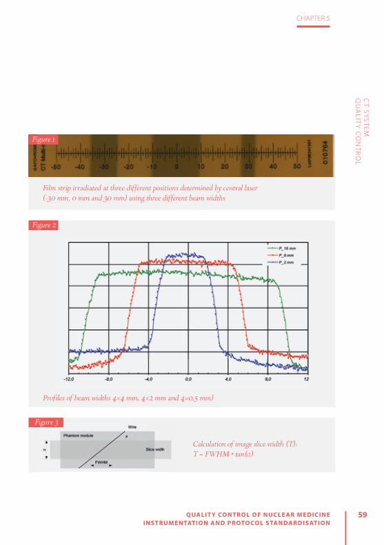
59
CHAPTER 5
QUALIT Y CONTROL OF NUCLEAR MEDICINE INSTRUMENTATION AND PROTOCOL STANDARDISATION
CT SY
STEM
QU
ALIT
Y C
ON
TRO
L
Film strip irradiated at three different positions determined by central laser (-30 mm, 0 mm and 30 mm) using three different beam widths
Figure 1
Figure 2
Profiles of beam widths 4×4 mm, 4×2 mm and 4×0.5 mm)
Calculation of image slice width (T): T = FWHM • tan(α)
Figure 3

60 QUALIT Y CONTROL OF NUCLEAR MEDICINE INSTRUMENTATION AND PROTOCOL STANDARDISATION
CHAPTER 5
CT SY
STEM
QU
ALIT
Y C
ON
TRO
L
Image quality tests
CT number uniformity and noise
Purpose. To check the uniformity of a CT image of a homogeneous object by measuring the CT numbers (Hounsfield units, HU) across the image of a homogeneous phantom [a CT dose index (CTDI) phantom can also be used].
Description. Proceed as follows: » Place the phantom on the table or head support and centre it vertically
and horizontally.» Choose the protocol most often used clinically (head or abdomen,
depending on the phantom). » Make a scout image and scan the phantom as would be done clinically.» On reconstructed images, select regions of interest (ROIs) in the centre
and in four places at the periphery (usually 12 h, 3 h, 6 h and 9 h).» Read the average CT number and standard deviation (noise).» Calculate the difference in average CT number between peripheral
ROIs and the centrally placed ROI.» Compare to reference values.
Tolerances. Tolerances for uniformity and noise are as follows:Uniformity: Deviation of CT number from specified value ±20 HUNoise: Deviation of noise from the specified values <25%
Artefact evaluation
Purpose. To evaluate the presence/absence of artefacts on images.
Equipment. Image quality phantom or other homogeneous phantom.
Description. Proceed as follows: » Place the phantom on the table or head support and centre it vertically
and horizontally.» Choose the most clinically used head protocol on the CT scanner.» Set the scanning plane in the middle of the homogeneous module and
make a scan. » Evaluate the image visually using a narrow window centred at the CT
number of the phantom material.
Tolerances. There should be no significant artefacts or distortions.

61
CHAPTER 5
QUALIT Y CONTROL OF NUCLEAR MEDICINE INSTRUMENTATION AND PROTOCOL STANDARDISATION
CT SY
STEM
QU
ALIT
Y C
ON
TRO
L
CT number accuracy
Purpose. To check that the CT numbers of different materials are within the range of expected values.
Equipment. Image quality phantom with different materials with known CT numbers (for example: CATPHAN, PRO-CT phantom, Mini CT QC Phantom, ACR CT accreditation phantom).
Description. Proceed as follows:» Place the phantom on the table or head support and centre it vertically
and horizontally.» Choose the most clinically used head protocol on the CT scanner.» Set the scanning plane in the middle of the phantom module contain-
ing different materials and make a scan.» Read the average values of CT numbers in the regions of interest (ROIs)
placed in the centre of each material in the module.» Compare the measured CT numbers with the reference values.
Tolerances. Deviation of CT numbers from specified values:± 10 HU for water and air± 20 HU for other materials
Spatial (high contrast) resolution
Purpose. To test the high contrast resolution of the CT scanner.
Equipment. Image quality phantom with high contrast resolution module.
Description. Proceed as follows: » Place the phantom on the table or head support and centre it vertically
and horizontally.» Choose the most clinically used head protocol.» Set the scanning plane in the middle of the phantom high contrast module. » Evaluate the number of resolved high contrast patterns.» Compare the result with the limiting values.
Tolerances. Deviation of spatial resolution ≤10% from manufacturer’s specification or 0.5 lp/mm, whichever is greater.

62 QUALIT Y CONTROL OF NUCLEAR MEDICINE INSTRUMENTATION AND PROTOCOL STANDARDISATION
CHAPTER 5
CT SY
STEM
QU
ALIT
Y C
ON
TRO
L
Image quality tests
Low contrast resolution
Purpose. To test the low contrast resolution of the CT scanner.
Equipment. Image quality phantom with low contrast resolution module.
Description. Proceed as follows:» Place the phantom on the table or head support and centre it vertically
and horizontally.» Choose the most clinically used head protocol.» Set the scanning plane in the middle of the phantom low contrast
module. » Evaluate the number of resolved low contrast objects.» Compare the result with the values at acceptance.

63
CHAPTER 5
QUALIT Y CONTROL OF NUCLEAR MEDICINE INSTRUMENTATION AND PROTOCOL STANDARDISATION
CT SY
STEM
QU
ALIT
Y C
ON
TRO
L
Image quality tests CT dosimetry tests
Accuracy of indicated dose parameters
Purpose. To check the accuracy of CT dose parameters (CTDIvol and/or DLP) displayed on the CT scanner control console.
Equipment. Calibrated dosimeter with 100-mm pencil ionisation chamber (CTDI probe) and PMMA CTDI phantom (16 cm and 32 cm PMMA).
Description. Proceed as follows: » Place the CTDI head phantom on the head support and centre it vertically and
horizontally using lasers. » Place the CTDI probe in the centre hole of the phantom. » Prepare the CTDI probe for the measurements as described in the manufacturer’s
manual.» Place the CTDI probe in the CTDI phantom in such a way that the centre of the
CTDI probe will be in the centre of the CTDI phantom.» Centre the table at this position (put the position to zero or note the actual position). » Make a scout image of the CTDI phantom. Set the start and end of the scan in
such a way that the centre of the CTDI phantom (CTDI probe) is in the middle of the scanning area.
» Set the table movement to 0. During this test, the table should stay in a fixed position.» Select the axial scan using exposure parameters close to the most frequently
used head scan. » Make a scan (1 rotation) and record the measured dose (PKL). Repeat to obtain at
least three measurements. The ionisation chamber measures the product of air-ker-ma and length (PKL), which is usually called the dose–length product (DLP). To calcu-late the CTDI, use the following formula:
CTDI = PKL
N • T where N•T is the nominal beam collimation (N slices of thickness T).
» The dose parameter, which is usually displayed on the CT scanner control console, is the weighted CT dose index CTDIw, which is a combination of mea-surements in the centre of the phantom and at the periphery (CTDIc and CTDIp, respectively):
CTDIP 2
3CTDIW = CTDIC +
1
3» Repeat the measurements by placing the CTDI probe in all four periphery holes (po-
sitions: 12 h, 3 h, 6 h, 9 h). All unused holes of the phantom must be filled with plugs.» Calculate the deviation of measured CTDI value to CTDI displayed on the control
console.
Tolerances. Deviation of measured dose from indicated dose <20%.
Notes. • Measurements should be done for all tube voltages that are used in practice.• The same procedure is followed using a body phantom (32 cm PMMA) and a standard body protocol. • Measurements of PKL in the centre can also be used to test some other properties of the CT scan-
ner, such as linearity with tube load (mAs), repeatability and dependence on beam width. • Instead of measurements within the phantom, measurements free in air can be performed. In this
case, an ionisation chamber is attached to the centre of the CT scanner gantry.

64 QUALIT Y CONTROL OF NUCLEAR MEDICINE INSTRUMENTATION AND PROTOCOL STANDARDISATION
CHAPTER 5
CT SY
STEM
QU
ALIT
Y C
ON
TRO
L
RADIOGRAPHERS’ TESTSThe role of the radiographer is to per-form and understand more frequent CT scanner tests (daily, weekly, monthly). The American College of Radiologist (ACR) and International Atomic Energy Agency (IAEA) have recommended that radiogra-phers should be competent to perform basic tests [2, 6]. More specifically, the ACR has recommended that the QC tests listed in Table 1 should be performed by the ra-diographer.
As a first action, a daily calibration (air calibration) should be performed before any other test. All tests must be performed using the same exposure and reconstruc-tion parameters in order to ensure that reproducible results are obtained. All un-expected changes in the constancy of measurements should be documented,
evaluated by the QC team and reported to the service engineer if necessary.
The main objective of the CT number test is to ensure that the relative calibra-tion of all CT numbers to water remains within acceptable limits and that quan-tum noise and electronic system noise do not increase. After scanning, the phantom CT number and its standard deviation in specified ROIs are recorded and compared with reference values set by the manufac-turer or medical physicist. If any remarks are documented or reported to the QC ra-diographer regarding artefacts on images, all image series must be analysed. The QC radiographer should try to identify possi-ble causes of artefacts on images.
In addition a visual QC checklist for ra-diographers has been suggested by the ACR[6] in order to ensure that other com-ponents of the CT scanner are functioning satisfactorily and to aid in avoiding repeat-ed scans. According to this checklist, the following items should be checked on a monthly basis:
» Table height indicator functioning » Table position indicator functioning » Angulation indicator functioning » Laser localisation light functioning » High-voltage cable/other cables safely attached (and not frayed)
» Acceptable smoothness of table motion » X-ray on indicator functioning » Exposure switch functioning
Radiographer QC Frequency
Water CT number and standard Deviation
Daily
Artefact evaluation Daily
Wet laser printer QC Weekly
Visual checklist Weekly
Dry laser printer QC Monthly
Display monitor QC Monthly
Table 1: CT QC tests for radiographers recommended by the ACR [6]

65
CHAPTER 5
QUALIT Y CONTROL OF NUCLEAR MEDICINE INSTRUMENTATION AND PROTOCOL STANDARDISATION
CT SY
STEM
QU
ALIT
Y C
ON
TRO
L
» Display window width/level » Panel switches/lights/meters working » Door interlocks functioning » Warning labels present » Intercom system functioning » Postings present » Service records present
Most modern CT scanners have their own QC procedure in which the test phantom provided with the scanner is used. In CT software QC packages, tests are automat-ed and measurement data are stored in CT software and can be accessed and an-alysed. Such tests are not time consuming and can therefore be performed relatively quickly. As such they can be easily incor-porated into a QA programme.
CONCLUSIONRadiographers must be a part of the QC team in order to secure, maintain or im-prove the health and well-being of the patient. Radiographers have a specific re-sponsibility to actively participate in QA and therefore should have the compe-tences required to perform QC tests for CT scanners and to evaluate the results of routine QA and QC tests.
The document “Guidelines on Radiation Protection Education and Training of Med-ical Professionals in the European Union”[7] is useful for the evaluation of existing ed-
ucational programmes. It provides an op-portunity to expand learning outcomes for educational institutions and improve the competencies of radiographers who already perform CT procedures. In order to ensure the provision of an effective, safe and efficient service, radiographers’ train-ing should incorporate instruction on QA and QC practices, to include: legislation, regulations and guidelines, test equip-ment and methodologies, programme de-sign and implementation and reporting[7]. With effective analysis and collaboration with medical physicists and radiologists, QC tests can also become an important training tool regarding the ways in which parameters monitored during these tests affect image quality and dose. Although QC phantoms cannot fully simulate pa-tients, they can still provide radiographers with useful knowledge on the perfor-mance of their CT scanner and can be used as a valuable tool in the optimisation process.

66 QUALIT Y CONTROL OF NUCLEAR MEDICINE INSTRUMENTATION AND PROTOCOL STANDARDISATION
CHAPTER 5
CT SY
STEM
QU
ALIT
Y C
ON
TRO
L
REFERENCES
1. Bauhs JA, Vrieze TJ, Primak AN, Bruesewitz MR, Mc-Collough CH. CT dosimetry: comparison of mea-surement techniques and devices. Radiographics 2008;28:245–253.
2. IAEA HHS-19. Quality Assurance Programme for Computed Tomography: Diagnostic and Therapy Applications. International Atomic Energy Agency, Human Health Series No. 19, 2012.
3. International Atomic Energy Agency. IAEA Human Health Series No. 19. Quality assurance programme for computed tomography: diagnostic and ther-apy applications. 2012. http://www-pub.iaea.org/MTCD/Publications/PDF/Pub1557_web.pdf
4. ImPACT CT Scanner Evaluation Group. ImPACT Infor-mation Leaflet 1. CT scanner acceptance testing. 2001. http://www.impactscan.org/download/acceptan-cetesting.pdf
5. American College of Radiology. ACR–AAPM techni-cal standard for diagnostic medical physics perfor-mance monitoring of computed tomography (CT) equipment. ACR Technical Standard 2012 Resolu-tion No. 34.
6. American College of Radiology. 2012 Computed Tomography. Quality Control Manual. 2012. https://www.acr.org/~/media/ACR%20No%20Index/Docu-ments/QC%20Manual/2012CTQCManual1a
7. European Commission. Radiation Protection No. 175. Guidelines on radiation protection education and training of medical professionals in the Euro-pean Union. 2014. https://ec.europa.eu/energy/en/radiation-protection-publications

6OPTIMISATION OF SPEC T AND SPEC T/C T – ACQUISITION AND RECONSTRUC TION
by Maximilien Vermandel and Hélène Lahousse
QU
ALIT
Y C
ON
TR
OL O
F NU
CLE
AR
ME
DIC
INE
INS
TR
UM
EN
TAT
ION
AN
D P
RO
TOC
OL S
TAN
DA
RD
ISA
TIO
N

68 QUALIT Y CONTROL OF NUCLEAR MEDICINE INSTRUMENTATION AND PROTOCOL STANDARDISATION
CHAPTER 6
OP
TIMISA
TION
OF SP
ECT A
ND
SPEC
T/CT –
AC
QU
ISITION
AN
D R
ECO
NSTR
UC
TION
INTRODUCTIONSingle-photon emission computed tomography (SPECT) is a medical imaging technique that allows in vivo measurements of the 3D distribution of gamma photon-emitting tracers. Technetium-99m (99mTc) is the radioactive isotope most commonly and widely used with SPECT imaging. 99mTc SPECT is mostly used in association with a vector in order to study the metabolism of a given organ.
The range of medical indications for SPECT is wide and includes bone resorption, studied using a bisphosphonate labelled with 99mTc, and renal function, investigated using 99mTc-labelled mercaptoacetyltrigly-cine (MAG3). 99mTc is also used with sesta-mibi to study myocardial perfusion. In neu-rology, brain perfusion analysis is achieved using 99mTc coupled with a neutral and li-pophilic complex whose molecular mass is sufficiently low to allow passage across the blood-brain barrier. However, some other isotopes are also used, such as iodine-123 in thyroid scintigraphy for hyperthyroidism or congenital hypothyroidism, indium-111 with a somatostatin analogue for neuro-endocrine tumours, krypton-81m for lung ventilation, thallium-201 for evaluation of cardiac viability and iodine-131 for the treatment of thyroid cancer.
For some of these applications, the vi-sual inspection of SPECT images provides sufficient information (e.g. bone fracture, arthritis, metastasis). For other applications, however, quantification on SPECT images
remains of interest. Indeed, for nephrology indications, quantification is expected to estimate renal function or cortical transit time. In cardiology, cardiac function can also be analysed using 99mTc-pertechne-tate-labelled red blood cells and calculat-ing the portion of isotope ejected during each heartbeat to determine the ejection fraction. In particular, radiotracer uptake is measured at the end of systole and dias-tole to estimate the ejection fraction, fol-lowed by evaluation of the kinetics in 3D. Moreover, prior to therapy, the avidity of the thyroid for iodine-123 may be assessed through measurement of the uptake rate, which serves as the basis for estimation of the iodine-131 activity to be prescribed.
Since the range of applications of SPECT imaging is wide, acquisition parameters must be chosen carefully, in accordance with the indication being investigated. Indeed, SPECT studies depend on the set-tings and methods used during acquisi-tion, reconstruction and post-processing. These parameters may drastically affect

69
CHAPTER 6
QUALIT Y CONTROL OF NUCLEAR MEDICINE INSTRUMENTATION AND PROTOCOL STANDARDISATION
the image quality and have to be carefully considered both when performing the ac-quisition itself and when interpreting the images.
The first section of this chapter presents important background information on the principles of SPECT instrumentation. The following section is devoted to the factors that affect image reconstruction quality and the parameters that must be consid-ered in order to achieve optimal acquisi-tion. Finally, some new advancements in SPECT are discussed.
SPECT AND SPECT/CT IMAGING INSTRUMENTATION
Gamma camera basicsA gamma camera is a set of planar detec-tors, usually two (dual-head), mounted on a gantry that enables simultaneous detector acquisition of parts of a patient’s body from different orientations. Detection of the gam-ma photons emitted by the decay of the ra-dioactive isotopes relies on the scintillation principle[1]. A basic sketch of a detector is shown in Fig. 1.
Photomultiplier tubes
Light guide
Scintillator
Collimators
Emitted gamma photon
Transverse view of a gamma camera detector
Figure 1

70 QUALIT Y CONTROL OF NUCLEAR MEDICINE INSTRUMENTATION AND PROTOCOL STANDARDISATION
CHAPTER 6
OP
TIMISA
TION
OF SP
ECT A
ND
SPEC
T/CT –
AC
QU
ISITION
AN
D R
ECO
NSTR
UC
TION
A gamma camera acquires two-dimen-sional projectional images of the distribu-tion of a radiotracer based on detection of the emitted photons. As illustrated in Fig. 1, an emitted photon (or event) passes through the collimator, which aims to se-lect photons from certain directions. The collimator consists of an array of holes, most often parallel holes, resembling an assembly of lead straws. On Fig. 1, non-par-allel photons would be stopped by the hole walls, the so-called septa. Once they have passed through the collimator, pho-tons interact with the scintillator, which is a large-area NaI(Tl) scintillation crystal, where they are absorbed; the absorbed energy is then re-emitted, with release of photons in the visible light spectrum. Ba-sically, the scintillator is a “wavelength con-verter” that converts high-energy photons to low-energy photons. The low-energy photons are then guided through the light guide to photomultiplier tubes (PMTs) that serve to convert the light signal into an electrical signal. PMTs are arranged in a 2D array in such a manner that the electrical signal collected at each PMT enables esti-mation of the 2D location of each event.
SPECTWhen used in static or whole-body mode, gamma camera detectors only allow for planar imaging of the radiotracer distribu-tion. However, in SPECT imaging, acquisi-
tion of multiple projections from multiple positions enables reconstruction of the three-dimensional distribution of gamma photon-emitting tracers (Fig. 2). SPECT is usually acquired in addition to planar scin-tigraphy in order to refi ne the diagnosis.
SPECT imaging is basically achieved by rotation of the detectors around the sub-ject. The motion of the detectors can be either step by step (SS) or continuous, the latter option being preferred for unstable patients (e.g. those with dementia). During continuous SPECT acquisition, continuous motion cycles are employed to maximise the number of events measured. In the event of unexpected patient movements, one or several cycles may be rejected be-fore the reconstruction phase. In contrast,
Illustration of the acquisition of multiple projections to achieve SPECT imaging
Figure 2

71
CHAPTER 6
QUALIT Y CONTROL OF NUCLEAR MEDICINE INSTRUMENTATION AND PROTOCOL STANDARDISATION
OP
TIMISA
TION
OF SP
ECT A
ND
SPEC
T/CT –
AC
QU
ISITION
AN
D R
ECO
NSTR
UC
TION
SS acquisition requires just a single cycle, which basically entails rotation of each de-tector through 180° around the subject in order to cover the full 360° range (for de-tector configuration in 180° or “H” mode). Step duration or speed and number of cy-cles in continuous mode depend primarily on the intensity of the radiotracer uptake and the patient’s condition.
Finally, image reconstruction is achieved using specific algorithms to render the spatial distribution of the radiotracer into matrices of 64×64, 128×128 or 256×256 pixels according to the location and size of the organ studied.
SPECT/CTImage reconstruction with conventional SPECT acquisitions cannot be corrected for attenuation or scatter when considering non-heterogeneous areas, an exception being the brain, for which Chang model-ling gives satisfactory results. For the pur-pose of such correction, the SPECT gantry can be coupled to a computed tomograph (CT) so that a CT scan can be acquired in conjunction with SPECT imaging. This hy-brid imaging system has two major advan-tages: First, the quasi-simultaneous acquisi-tion of SPECT and CT allows for the fusion of functional and anatomical data with minimal concerns regarding registration. Second, the CT images, converted to a map of electronic densities, are used for the pur-
pose of attenuation and scatter correction during tomographic reconstruction.
The use of hybrid technologies may entail significantly increased radiation ex-posure for the patient. In order to reduce the exposure while maintaining good im-age quality, manufacturers have released systems that automatically modulate the tube current (mAs) according to the den-sity of tissues being explored. Basically, the system automatically adapts, in real time, the tube current to the thickness of tissue crossed by the X-ray beam as deduced from the topogram acquisition (Fig. 3). For example, the X-ray beam is more strongly attenuated by the shoulders than by the abdomen owing to the lower density of the latter; thus decreasing the tube current for the abdominal exploration allows for a substantial dose reduction. However, in specific cases the dose reduction system may not be activated. For instance, when the CT scan is only acquired for the pur-pose of attenuation correction, minimal dose exposure is expected and thus high voltage and tube current are carefully bal-anced to achieve this goal.
Collimator In the chain of acquisition, the collimator type is the first element to be considered for optimisation of SPECT image acquisition since it closely depends on (1) the energy of the emitted photons to be measured and

72 QUALIT Y CONTROL OF NUCLEAR MEDICINE INSTRUMENTATION AND PROTOCOL STANDARDISATION
CHAPTER 6
Illustration of a dose reduction system. a) Estimation of the mAs on the Z-axis according to the topogram. b) Dose level for different locations when using the dose reduction system
Figure 3OP
TIMISA
TION
OF SP
ECT A
ND
SPEC
T/CT –
AC
QU
ISITION
AN
D R
ECO
NSTR
UC
TION
(a)(a)
(b)
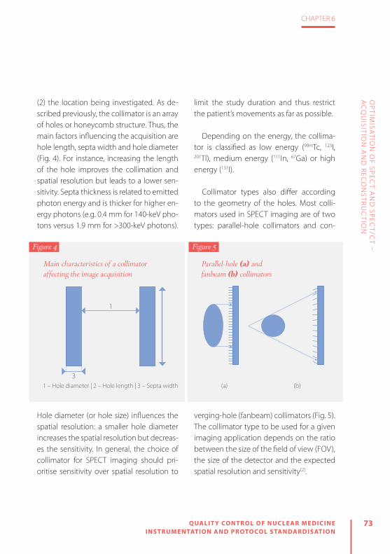
73
CHAPTER 6
QUALIT Y CONTROL OF NUCLEAR MEDICINE INSTRUMENTATION AND PROTOCOL STANDARDISATION
OP
TIMISA
TION
OF SP
ECT A
ND
SPEC
T/CT –
AC
QU
ISITION
AN
D R
ECO
NSTR
UC
TION
(2) the location being investigated. As de-scribed previously, the collimator is an array of holes or honeycomb structure. Thus, the main factors influencing the acquisition are hole length, septa width and hole diameter (Fig. 4). For instance, increasing the length of the hole improves the collimation and spatial resolution but leads to a lower sen-sitivity. Septa thickness is related to emitted photon energy and is thicker for higher en-ergy photons (e.g. 0.4 mm for 140-keV pho-tons versus 1.9 mm for >300-keV photons).
Hole diameter (or hole size) influences the spatial resolution: a smaller hole diameter increases the spatial resolution but decreas-es the sensitivity. In general, the choice of collimator for SPECT imaging should pri-oritise sensitivity over spatial resolution to
limit the study duration and thus restrict the patient’s movements as far as possible.
Depending on the energy, the collima-tor is classified as low energy (99mTc, 123I, 201Tl), medium energy (111In, 67Ga) or high energy (131I).
Collimator types also differ according to the geometry of the holes. Most colli-mators used in SPECT imaging are of two types: parallel-hole collimators and con-
verging-hole (fanbeam) collimators (Fig. 5). The collimator type to be used for a given imaging application depends on the ratio between the size of the field of view (FOV), the size of the detector and the expected spatial resolution and sensitivity[2].
Main characteristics of a collimator affecting the image acquisition
1 – Hole diameter | 2 – Hole length | 3 – Septa width
1
3
Figure 4
(a) (b)
Parallel-hole (a) and fanbeam (b) collimators
Figure 5

74 QUALIT Y CONTROL OF NUCLEAR MEDICINE INSTRUMENTATION AND PROTOCOL STANDARDISATION
CHAPTER 6
OP
TIMISA
TION
OF SP
ECT A
ND
SPEC
T/CT –
AC
QU
ISITION
AN
D R
ECO
NSTR
UC
TION
The parallel-hole collimator is the histori-cal design by Anger and this is still the stan-dard collimator employed in clinical prac-tice. For a parallel-hole collimator, the point source sensitivity is the same over the whole FOV. When the organ or location under in-vestigation is smaller than the FOV, the use of fanbeam collimators results in improved performance in terms of both sensitivity and spatial resolution[3]. This latter configu-ration may be preferred for brain imaging, for instance.
Finally, for cardiology imaging, specific collimators allowing for faster cardiac SPECT acquisition have recently been released[4].
CrystalInteraction of emitted photons with the scintillator crystal leads to the emission of fluorescence photons (light) in all direc-tions. Only a limited fraction of light trav-els to the PMT. Thus, the scintillator is sur-rounded by a reflector material on all sur-faces, except the surface in contact with the PMT, in order to maximise light col-lection at the PMT. Additionally, the crys-tal is coupled to the PMT array through a transparent medium of the same index of refraction as the crystal so that reflection is minimised at the interface between the PMT and the scintillator.
The thickness of the crystal impacts on both sensitivity and spatial resolution. As illustrated in Fig. 6, a thick crystal will
improve photon interactions and the sen-sitivity. Indeed, a thick crystal increases the probability of total absorption of the incident photons when the energy is high. However, the resultant gain in sensitivity comes at the cost of a reduction in spatial resolution.
The thickness of the crystal/scintillator is specific to the gamma camera and de-pends on the type of radiotracer used. For a low-energy tracer, a thin crystal should be preferred (3/8 inch) while a thicker crystal (5/8 inch) is to be preferred for higher energy tracers.
Finally, the choice of crystal thickness depends on the type of daily use. For in-stance, SPECT with 99mTc will be acquired using a thin crystal, whereas if most uses involve 131I, a thick crystal will be pre-ferred.
Photomultiplier tubesLight emitted inside the crystal is collect-ed by the PMTs in order to convert the light signal into an electrical signal (Fig. 7). PMTs comprise an evacuated glass package with a photocathode, to convert light to electrons, followed by a string of electron-multiplying dynodes. The ampli-fication gain is high (>106). High voltage for the whole PMT array and gain for each PMT have to be carefully fine-tuned in or-der to achieve a similar response on all the FOV for both the energy of incident pho-

75
CHAPTER 6
QUALIT Y CONTROL OF NUCLEAR MEDICINE INSTRUMENTATION AND PROTOCOL STANDARDISATION
OP
TIMISA
TION
OF SP
ECT A
ND
SPEC
T/CT –
AC
QU
ISITION
AN
D R
ECO
NSTR
UC
TION
tons and the sensitivity. Furthermore, the response of each detector has to be ho-mogeneous independently of the angle of
the gantry. Variation in the PMT response according to angle may have an impact on the reconstructed image.
Illustration of the effect of the crystal thickness on light collection at the PMT array. In (a), the crystal is thicker, improving the sensitivity but limiting the spatial resolution (the cone of light collected at the PMT array is wider). In (b), not all of the photons interact with the crystal but the spatial resolution is higher (i.e. the cone of light collected at the PMT is narrower).
PMT array
(a) (b)
PMT array
Illustration of a PMT converting light into an electrical signal
Figure 6
Figure 7

76 QUALIT Y CONTROL OF NUCLEAR MEDICINE INSTRUMENTATION AND PROTOCOL STANDARDISATION
CHAPTER 6
IMAGE RECONSTRUCTION
AlgorithmsReconstruction of the images from projec-tions is a crucial stage in SPECT imaging. After the acquisition process, each pixel of the projection images at each angular position contains the number of events detected. The principle of reconstruction consists in building a slice from the differ-ent projections. Figure 8 shows an example of reconstruction from planar acquisition.
Basically, two types of reconstruction are used: analytic methods and iterative methods[5]. Analytic methods are based on a back-projection algorithm, the most
frequently used being filtered back pro-jection (FBP). FBP consists in filtering pro-jection data before propagating the pixel value on the slice to be reconstructed. Because FBP is more computationally ef-ficient (fast), it has long been preferred. However, FBP requires a huge amount of projection data to enable well-defined im-ages to be obtained. In view of the high number of projections acquired during X-Ray Computerised Tomography (CT) examination, FBP leads to satisfactory image reconstruction. However, the low resolution of scintigraphic imaging and the low number of projections available prevent proper rendering of the three-di-
a) Two projections acquired at two angular positions. b) Reconstruction of the slice from the events contain in each pixel of the projections
X
10
X
X
9
14
11
X
16
X
X
X
8
X
X
4
10
2
4
9
14
11
2
16
10
4
3
8
2
3
(a) (b)
Figure 8
OP
TIMISA
TION
OF SP
ECT A
ND
SPEC
T/CT –
AC
QU
ISITION
AN
D R
ECO
NSTR
UC
TION

77
CHAPTER 6
QUALIT Y CONTROL OF NUCLEAR MEDICINE INSTRUMENTATION AND PROTOCOL STANDARDISATION
OP
TIMISA
TION
OF SP
ECT A
ND
SPEC
T/CT –
AC
QU
ISITION
AN
D R
ECO
NSTR
UC
TION
mensional distribution of the radiotracer when reconstructed using FBP methods. Iterative methods address this issue and, thanks to the performance of the most recent generations of computers, they are now commonly used for SPECT image re-construction. The general concept of itera-tive methods is to solve p=A×f where p is a vector of the projection data (i.e. projec-tions acquired), f is a vector representing the three-dimensional distribution to be reconstructed (i.e. tomographic images) and A is a function of projection (i.e. geom-etry of acquisition). The principle of itera-tive algorithms is to find a solution (i.e. f) by successive estimates. Ordered subsets expectation maximisation (OSEM) is the most commonly applied algorithm and is based on the maximum likelihood ex-pectation maximisation (MLEM). The aim of MLEM algorithms is to find a solution as the best estimate of f than can produce projections p with the highest likelihood. OSEM allows acceleration of computation by dividing the set of projections into sub-sets (Fig. 9). Thus, independently from the acquisition duration and the numbers of projections, the main factors influencing the image quality are the number of sub-sets and the numbers of iterations.
Finally, the higher the number of itera-tions, the higher is the spatial resolution, but with an increase in the noise level, and the higher the number of subsets,
the faster is the convergence. According-ly, the number of subsets and the number of iterations should be carefully balanced. Indeed, if the number of subsets and it-erations is too small, the algorithm does not converge and the result is a poorly contrasted and blurred image, while if the number of iterations is too large in respect to the number of subsets, the reconstruct-ed image displays an increased noise level (Figs. 10 and 11).
Other benefits of iterative reconstruc-tion are that the projection function may include different acquisition parameters in order to optimise image rendering. Indeed, spatial resolution (both intrinsic and ex-trinsic, depending on the collimator used), attenuation by the patient, Compton scat-ter (in the patient, collimator and/or crys-
(a) (b)
Examples of ordered subsets: a) set of projections divided into four subsets; b) set of projections divided into two subsets
Figure 9

78 QUALIT Y CONTROL OF NUCLEAR MEDICINE INSTRUMENTATION AND PROTOCOL STANDARDISATION
CHAPTER 6
Figure 10
Figure 11
Example of the poor contrast and blurring that occur if the number of subsets and iterations is too small. Tomographic reconstruction of a bone study (99mTc), no attenuation reconstruction, 5-mm Gaussian post-filter, 64 angular positions (128 projections). Reconstruction was achieved with OSEM, with 4 iterations and either 4 (a) or 16 subsets (b)
Example of the increase in noise level that occurs with a higher number of iterations. Tomographic reconstruction of a bone study (99mTc), no attenuation reconstruction, 5-mm Gaussian post-filter, 64 angular positions (128 projections). Reconstruction was achieved with OSEM, 4 subsets and an increasing number of iterations: 4 (a), 8 (b), 16 (c), and 64 (d)
OP
TIMISA
TION
OF SP
ECT A
ND
SPEC
T/CT –
AC
QU
ISITION
AN
D R
ECO
NSTR
UC
TION
(a) 4 iterations, 4 subsets
(a) 4i, 4s
(c) 16i, 4s
(b) 4 iterations, 16 subsets
(b) 8i; 4s
(d) 64i, 4s

79
CHAPTER 6
QUALIT Y CONTROL OF NUCLEAR MEDICINE INSTRUMENTATION AND PROTOCOL STANDARDISATION
OP
TIMISA
TION
OF SP
ECT A
ND
SPEC
T/CT –
AC
QU
ISITION
AN
D R
ECO
NSTR
UC
TION
tal) and collimator septal penetration can be modelled to optimise the reconstruc-tion. These reconstruction options with the possibility of applying post-processing filters must be implemented within acqui-sition and/or post-processing software to facilitate the optimisation of image quality.
Attenuation correctionEmitted photons have different trajecto-ries across the patient’s body, such that those emitted from deeper locations are
subject to higher attenuation on their paths. In other words, a photon emitted from the surface of the patient is less atten-uated than a photon emitted from a deep location. As a consequence, the emission of photons from deeper locations are un-derestimated on the projections (Fig. 12).
For some locations, attenuation cor-rection may be achieved with the Chang algorithm. However, this algorithm is only suitable for a homogeneous location, such
Example of photons emitted from different depths, with more attenuation occurring for photons emitted from deeper locations
Figure 12

80 QUALIT Y CONTROL OF NUCLEAR MEDICINE INSTRUMENTATION AND PROTOCOL STANDARDISATION
CHAPTER 6
OP
TIMISA
TION
OF SP
ECT A
ND
SPEC
T/CT –
AC
QU
ISITION
AN
D R
ECO
NSTR
UC
TION
Examples of images reconstructed without and with the use of attenuation correction based on CT acquisition. a,b) A phantom filled with 99mTc solution and images reconstructed without (a) and with (b) attenuation correction. c,d) A plain phantom with two sources of 177Lu in the centre and images reconstructed without (c) and with (d) attenuation correction. e,f) Patient images reconstructed from a 99mTc study without (e) and with (f) attenuation correction. The images clearly show that without attenuation correction, events at depth are underestimated.
(a) (b)
(c) (d)
(e) (f )
Figure 13

81
CHAPTER 6
QUALIT Y CONTROL OF NUCLEAR MEDICINE INSTRUMENTATION AND PROTOCOL STANDARDISATION
OP
TIMISA
TION
OF SP
ECT A
ND
SPEC
T/CT –
AC
QU
ISITION
AN
D R
ECO
NSTR
UC
TION
as the brain. For heterogeneous areas, an electronic density map of tissues acquired from CT is preferred for attenuation cor-rection. Figure 13 shows examples of re-construction without and with the use of attenuation correction based on CT acqui-sition.
Matrix size and zoomEvents detected on a projection are distrib-uted on a grid, a so-called matrix. Each pic-ture element (pixel) of the matrix basically covers the entire FOV and contains the total number of events detected during the acquisition. A matrix is described by the number of rows (m) and columns (n) defi ning its size: m × n. For SPECT imag-ing, standard matrix sizes are 128×128 or
256×256 up to 512×512. The size of the ac-quisition matrix will defi ne the size of the tomographic images to be reconstructed. Thus, a higher matrix size will result in re-cording of fi ner details within the limits of the intrinsic spatial resolution. Matrix size selection directly aff ects the signal to noise ratio (SNR) of acquired data. Indeed, larger matrix sizes lead to events being spread over a greater number of pixels; according-ly, to maintain the same SNR with a larger matrix, the acquisition duration must be longer so as to increase the number of events. Thus, acquisition duration and ma-trix size must be carefully balanced.
Zoom is used for the magnifi cation of the object (e.g. specifi c body location, Fig. 14) while keeping the matrix size un-
Illustration of a 4x4 acquisition matrix for the study of a kidney. a) The matrix covers the entire FOV. b) A zoom of 2 is applied during the acquisition to achieve higher spatial resolution.
(a) (b)
Figure 14

82 QUALIT Y CONTROL OF NUCLEAR MEDICINE INSTRUMENTATION AND PROTOCOL STANDARDISATION
CHAPTER 6
OP
TIMISA
TION
OF SP
ECT A
ND
SPEC
T/CT –
AC
QU
ISITION
AN
D R
ECO
NSTR
UC
TION
changed. For example, an unzoomed im-age with a 128x128 matrix and a pixel size of 5 mm will allow a pixel size of 2.5 mm with the use of a zoom of 2. Finally, the zoom allows for acquisition of the same matrix size on a limited FOV area but the duration of frame acquisition may need to be altered in order to maintain the SNR.
NEW ADVANCEMENTS IN SPECTToday, the newest CT scan reconstruction technologies, including iterative recon-struction, are contributing in reducing patients’ radiation exposure. Additionally, new detection technologies will also help to minimise this exposure. Indeed, the new detectors based on semiconductor technology (CZT: cadmium-zinc-telluride) directly convert emitted photons into an electrical pulse without the use of a scintil-lator or PMT. Thus, CZT detectors increase spatial resolution, energy resolution and sensitivity. Finally, the improved sensitiv-ity of this technology, initially developed for cardiology applications[6], means that less radiotracer activity is required for an equivalent image quality and allows re-duction of the study duration, thereby avoiding movement artefacts and reduc-ing overall patient exposure[7].
CONCLUSIONOptimisation of SPECT/CT acquisition re-lies on multiple factors. Obviously, the pro-tocol acquisition may be optimised taking into account both the technical aspects detailed above and the ALARA principle (whereby the radiation exposure is kept “as low as reasonably achievable”). Howev-er, patient status must be taken into con-sideration. Indeed, the patient’s age and comorbidities may influence the design of the acquisition protocol, which thus may vary depending on the context. For instance, the exploration of pelvic pain by means of bone scintigraphy in an elderly patient largely justifies a CT acquisition with SPECT because (1) risk of fracture of the pelvis is high and the bladder uptake may prevent study of the sacrum and (2) the CT dose exposure remains acceptable since SPECT alone contributes the major-ity of the patient’s overall exposure[8]. Fur-thermore, the duration of the SPECT/CT acquisition may be reduced if uptake on planar scintigraphy is high. On the other hand, in a child with gait abnormalities, acquisition of a SPECT/CT after planar study may be considered unnecessary if a complementary examination is scheduled (e.g. MRI), thereby avoiding needless dose exposure.
83
CHAPTER 6
QUALIT Y CONTROL OF NUCLEAR MEDICINE INSTRUMENTATION AND PROTOCOL STANDARDISATION
OP
TIMISA
TION
OF SP
ECT A
ND
SPEC
T/CT –
AC
QU
ISITION
AN
D R
ECO
NSTR
UC
TION
REFERENCES
1. Peterson TE, Furenlid LR. SPECT detectors: The Anger camera and beyond. Phys Med Biol 2011;56:R145–R182.
2. Van Audenhaege K, Van Holen R, Vandenberghe S, Vanhove C, Metzler SD, Moore SC. Review of SPECT collimator selection, optimization, and fabrica-tion for clinical and preclinical imaging. Med Phys 2015;42:4796–4813.
3. Tsui BM, Gullberg GT, Edgerton ER, Gilland DR, Perry JR, McCartney WH. Design and clinical utility of a fan beam collimator for SPECT imaging of the head. J Nucl Med 1986;27:810–819.
4. Gremillet E, Agostini D. How to use cardiac IQ•SPECT routinely? An overview of tips and tricks from prac-tical experience to the literature. Eur J Nucl Med Mol Imaging 2016;43:707–710.
5. Bruyant PP. Analytic and iterative reconstruction al-gorithms in SPECT. J Nucl Med 2002;43:1343–1358.
6. Mouden M, Timmer JR, Ottervanger JP, Reiffers S, Oostdijk AH, Knollema S, et al. Impact of a new ul-trafast CZT SPECT camera for myocardial perfusion imaging: Fewer equivocal results and lower radiation dose. Eur J Nucl Med Mol Imaging 2012;39:1048–1055.
7. Agostini D, Marie PY, Ben-Haim S, Rouzet F, Songy B, Giordano A, et al. Performance of cardiac cadmi-um-zinc-telluride gamma camera imaging in coro-nary artery disease: A review from the cardiovascular committee of the european association of nucle-ar medicine (EANM). Eur J Nucl Med Mol Imaging 2016;43:2423–2432.
8. Rausch I, Fuchsel FG, Kuderer C, Hentschel M, Beyer T. Radiation exposure levels of routine SPECT/CT imag-ing protocols. Eur J Radiol 2016;85:1627–1636.


7OPTIMISATION OF PE T/C T — ACQUISITION AND RECONSTRUC TION
by Leesa Ross and Dusty York
QU
ALIT
Y C
ON
TR
OL O
F NU
CLE
AR
ME
DIC
INE
INS
TR
UM
EN
TAT
ION
AN
D P
RO
TOC
OL S
TAN
DA
RD
ISA
TIO
N

86 QUALIT Y CONTROL OF NUCLEAR MEDICINE INSTRUMENTATION AND PROTOCOL STANDARDISATION
CHAPTER 7
OP
TIMISA
TION
OF P
ET/CT —
A
CQ
UISITIO
N A
ND
REC
ON
STRU
CTIO
N
INTRODUCTIONFootnote: This chapter will mainly focus on whole-body FDG imaging. For specific brain and cardiac PET/CT, please refer to the Tech Guides on Brain Imaging and Myocardial Perfusion Imaging.
Positron emission tomography (PET) is able to evaluate the metabolic activity of target tissues. The principle behind PET is that two 511-keV photons are emitted from an annihilation reaction between a positron and an electron. When the 511-keV photons are detected simultaneously by the PET scanner, the process of image formation is begun. The isotopes car-bon-11 and germanium-68 are frequently used; however, the most common PET ra-
diopharmaceutical is fluorine-18 fluorode-oxyglucose (18F-FDG), which can be used for total body imaging as well as for brain and cardiac imaging (Fig. 1). Acquisition and reconstruction are important steps in the scanning process. Without standards and protocols, the patient outcome may suffer. It is best to use the manufactur-er’s settings; however, with advances and changes in the profession, due to research, optimisation may require modifications.
A: A PET/CT image consisting of coronal whole-body CT image. B: PET image with CT attenuation correction. C: Fused PET/CT image (C). Courtesy of the Journal of Nuclear Medicine Technology (JNMT)[1]
Figure 1

87
CHAPTER 7
QUALIT Y CONTROL OF NUCLEAR MEDICINE INSTRUMENTATION AND PROTOCOL STANDARDISATION
OP
TIMISA
TION
OF P
ET/CT —
A
CQ
UISITIO
N A
ND
REC
ON
STRU
CTIO
N
Patient preparation for a whole-body PET scan with 18F-FDG includes no con-sumption of food, simple carbohydrates or liquids other than plain (unflavoured) water for 4 h prior to 18F-FDG injection for the non-diabetic patient. It is also recom-mended that the patient should not con-sume food after midnight the night before the study. A low carbohydrate diet is pre-ferred for one day prior to the study[2].
The patient’s blood glucose level should be evaluated prior to injection of 18F-FDG. For clinical studies involving the whole body, the blood glucose level should be lower than 11 mmol/L (~200 mg/dL). Pa-tients with glucose levels out of this range may be excluded from the study[3]. The patient should be injected in a quiet area and remain in that location with the lights dimmed for 60–120 min post injection. The patient should be kept warm and re-quested to sit still during the waiting pe-riod. For the purposes of radiation safety and compliance with ALARA, explanation of the procedure should be completed pri-or to injection, thereby reducing radiation exposure to the technologist.
Before the patient is positioned on the table, he or she should be instructed to empty the bladder to enhance comfort and decrease the opportunity for artefacts. The patient is then placed in the supine position, with arms elevated and support-ed above the head for torso acquisition
and by the sides for head and neck im-aging. Elevating the arms when imaging the torso will reduce beam-hardening ar-tefacts, as well as artefacts caused by trun-cation of the measured field of view (FOV). If imaging the head and neck area, as well as the torso, it is beneficial to acquire two separate acquisitions — one with the arms elevated for torso acquisition and one with the arms by the sides for head and neck imaging. In radiation therapy treat-ment planning, the position of the patient should be the same as for radiotherapy treatment set-up.
Skull base to proximal thigh imaging is recommended for most tumour imaging, typically from the external auditory me-atus to the mid-thigh region. For tumours with an increased potential for scalp, skull, or brain involvement or for lower extrem-ity involvement, whole-body imaging is performed. Limited-area imaging can be performed when there is a specific area of interest.
PET acquisition and reconstruction protocols should always begin with the factory-recommended settings. Any mod-ifications in protocol should be evaluated carefully to avoid affecting patient images in a negative manner. Over time, software upgrades and changes in professional rec-ommendations may occur that warrant modification of the factory-recommended settings.
88 QUALIT Y CONTROL OF NUCLEAR MEDICINE INSTRUMENTATION AND PROTOCOL STANDARDISATION
CHAPTER 7
OP
TIMISA
TION
OF P
ET/CT —
A
CQ
UISITIO
N A
ND
REC
ON
STRU
CTIO
N
Many brands of scanners are available for use by the nuclear medicine commu-nity. Selection is based on patient popula-tion, department needs, costs and facility vendor preference.
Various professional organisations and societies have developed performance guidelines, including the American Col-lege of Radiology (ACR). The ACR-rec-ommended scanner specifications are as follows:
For the CT scanner:a. Spiral scan time: <5 s (<2 s is preferable) b. Slice thickness and collimation:
<5 mm (<2 mm is preferable)c. Limiting spatial resolution: >8 lp/cm
for >32-cm display field of view (DFOV) and >10 lp/cm for <24-cm DFOV
For the PET scanner:a. In-plane spatial resolution: <6.5 mmb. Axial resolution: <6.5 mmc. Sensitivity (3D): >4.0 cps/kBqd. Sensitivity (2D): >1.0 cps/kBqe. Uniformity: <5%
For the combined PET/CT scanner:a. Maximum co-scan range (CT and PET):
>160 cmb. Maximum patient weight:
>159 kgc. Patient port diameter: >59 cm
EMISSION IMAGESThe acquisition time varies from 2 to 5 min or longer per bed position for body imaging. Continuous bed movement may also be utilised to image the pa-tient, if the scanner has that capability. Acquisition time varies according to the administered activity, the patient body weight, 2D versus 3D and the count rate capability and sensitivity of the PET scan-ner. The average imaging time for skull to mid-thigh acquisition is 15–45 min. A variation in time per bed position can be used if the system is capable of that tech-nique. This enables a faster scan time by permitting reduction in the time per bed position in areas outside of the torso be-cause those areas have less attenuation. Administration of a higher activity can also reduce the image acquisition time, but compliance with ALARA principles requires a lower dose and longer acqui-sition. Formulas are available to calculate dose taking into account bed overlap and patient weight, and whether maximum or minimum activity is used.
When using systems with a high count rate capability, 18F-FDG activity and scan duration for each bed position must be adjusted so that the product of the 18F-FDG activity and scan duration ±10% is equal to or greater than the specifications set out below[3]:

89
CHAPTER 7
QUALIT Y CONTROL OF NUCLEAR MEDICINE INSTRUMENTATION AND PROTOCOL STANDARDISATION
OP
TIMISA
TION
OF P
ET/CT —
A
CQ
UISITIO
N A
ND
REC
ON
STRU
CTIO
N
The figures for systems with bed overlap of <25% are:» Product of <MBq/kg × min/bed >
27.5 for 2D scans» Product of MBq/kg × min/bed >
13.8 for 3D scans
The dosage is then calculated as follows: » FDG activity in MBq for 2D scans = 27.5 × weight/(min/bed)
» FDG activity in MBq for 3D scans = 13.8 × weight/(min/bed)
And for systems with a bed overlap of 50%:
» Product of MBq/kg × min/bed > 6.9 (3D only)
» FDG activity in MBq = 6.9 × weight/ (min/bed)
No matter what technique is used to deter-mine the administered activity, the activity within the FOV should not exceed the peak count rate capability of the system.
2D VERSUS 3D ACQUISITIONPET images can be acquired in 2D or 3D mode. Earlier scanners used septa made of lead or tungsten that were positioned within the FOV. The septa provided a way to limit photons emitted or scattered out-side the transverse or transaxial plane to the detector. This limited the sensitivity of
the scanner. Acquisition systems with sep-ta are 2D scanners. Recent scanners devel-oped in the early 2000s use 3D technology and do not use septa[5]. Some scanners are capable of 2D and 3D acquisition[6].
3D acquisition increases sensitivity four to ten times due to an increase in lines of response (LORs) resulting from the detec-tion of cross-plane events[7]. Removal of septa in 3D acquisitions provides a higher detection probability. Increased sensitivity also results in increased random and scat-ter contributions. To compensate, these scanners are also equipped with new and fast detectors using new scintillation crys-tals. Faster crystals provide better count rate performance. A short coincidence timing window can be applied, which re-sults in a reduction of random and scatter coincidences. Due to low sensitivity at the edge of the detector ring in 3D acquisition, bed overlap from one bed position to the next may be warranted. In continuous motion acquisition there is no need for overlap, as there is uniform detector sen-sitivity over the patient[6].
DYNAMIC IMAGESDynamic images may also be obtained when a specific area is to be imaged as a flow study. A bed position of 15–26 cm is capable of imaging smaller regions. Dy-namic PET images are similar to dynamic

90 QUALIT Y CONTROL OF NUCLEAR MEDICINE INSTRUMENTATION AND PROTOCOL STANDARDISATION
CHAPTER 7
OP
TIMISA
TION
OF P
ET/CT —
A
CQ
UISITIO
N A
ND
REC
ON
STRU
CTIO
N
gamma camera images. Dynamic PET im-aging acquires complete volume images within a set time frame. Typical times for evaluating arterial flow are 2 s per image followed by a longer imaging time to demonstrate further uptake of the tracer over time[7].
LIST MODEIf the system is capable of it, images may be acquired in list mode. Events, timing markers and physiological gating markers are stored as lists in list mode; the data may be rebinned (recreated) during use of cardiac or respiratory gating. These data can then be formatted into sinograms for reconstruction. Time of flight scanners are capable of acquiring in list mode; there-fore, list mode may become the standard method for acquiring data[7].
DUAL TIME POINTFor certain disease states, dual time point imaging may be beneficial. This involves an initial scan, a waiting period and then a delayed scan. In the case of tumour im-aging there will be an increase in activity over time, whereas in infections there will be a decrease over time[6]. Thus delayed imaging can increase the specificity of whether activity is due to either tumour or inflammation.
STANDARD UPTAKE VALUEReported data should include the type of isotope utilised, the patient’s height and body weight, FDG activity administered, assay time and time of injection. This aids in standardised uptake value (SUV) reporting. SUV is used to quantitate ac-tivity in body organs, abnormalities or the total body and supplements visual interpretation of an area. It is derived as follows[8]:
SUVBW = (Region of interest (kBq/mL)
Injected activity with decay-corrected residual
subtracted (MBq/kg)/patient weight (kg) where BW is
body weight.
ACQUISITION PARAMETERSFurther instructions on obtaining the emission image include that the online randoms correction should be based on the “delayed coincidence time window” technique or randoms correction using a model based on (block) single count rates. This has an effect on image con-trast. Decay correction must be ‘on’, as well. Shorter image times result because of the increase in contrast that occurs from the high-quality image obtained with time of flight[3].

91
CHAPTER 7
QUALIT Y CONTROL OF NUCLEAR MEDICINE INSTRUMENTATION AND PROTOCOL STANDARDISATION
OP
TIMISA
TION
OF P
ET/CT —
A
CQ
UISITIO
N A
ND
REC
ON
STRU
CTIO
N
TRANSMISSION IMAGEThe typical PET/CT scan involves the ac-quisition of a topogram followed by single or multiple helical CT scans. CT can be performed for attenuation correction, ana-tomical alignment or acquisition of an op-timised diagnostic scan. When obtaining attenuation-corrected/anatomical align-ment images, a low milliampere-seconds setting is used to reduce the radiation dose. In an optimised diagnostic CT scan, standard CT milliampere-seconds settings are used. This results in better spatial res-olution of the CT scan. Modulation of the tube current may also be used to reduce radiation dose in patients without metal implants[3]. This can be accomplished with dose reduction software developed by the manufacturer of the scanner, when avail-able, and enables optimal low mA and kV settings to be used. It is always the case that selection of CT acquisition param-eters, such as pitch, rotation time, slice thickness, increment, voltage and tube current, depends on the purpose of the CT scan. If the CT image is obtained solely for the purpose of attenuation correction, voltage and current can be reduced to near the lowest the scanner is capable of producing and still be acceptable.
Pitch is the ratio of table movement through the gantry during one 360° rota-tion, relative to beam collimation. The low-er the pitch, the more the overlap. A pitch
of 1.0 will result in no spacing. A pitch of less than 1.0 results in overlap, while a pitch of 2.0, or higher, results in spaces between slices, equal to the thickness of the slice. Pitch is inversely proportional to patient dose. Increasing the table speed or pitch reduces the radiation dose in pro-portion to the increase in pitch (unless the scanner automatically increases mA with increase in pitch). However, image quality will be reduced[9].
Slice thickness and increment define the positional relationship of image slices and the amount of separation between the slices or potential overlap. If the slice thickness is equal to the increment, there is no separation. If the slice thickness is less than the increment there is overlap. It is beneficial to have some overlap when attempting to detect smaller lesions[9].
Regarding rotation time, at slower times a compensatory increase in mA is required to add more X-rays to the image. The slower the rotation time, the more blurred the image. A faster rotation time is ben-eficial when body motion is a concern. Increasing the rotation time will result in better resolution because each image is generated from more projections[9].
Other CT acquisition parameters are voltage and tube current. Denser areas re-quire a higher voltage. This voltage is mea-sured in kVp. The higher the mA setting, or tube current, the higher the quality of the

92 QUALIT Y CONTROL OF NUCLEAR MEDICINE INSTRUMENTATION AND PROTOCOL STANDARDISATION
CHAPTER 7
OP
TIMISA
TION
OF P
ET/CT —
A
CQ
UISITIO
N A
ND
REC
ON
STRU
CTIO
N
image acquired; however, radiation dose will increase, as well[9].
Attenuation correction is critical for both visual and quantitative accuracy of PET images. Attenuation will vary from patient to patient due to body make-up and size. The only way to accurately eval-uate the attenuation coefficient is to pass a beam of radiation through the body and measure the attenuation. The first commercial PET/CT scanners appeared in 2001. By 2006 PET-only systems were
no longer available. Since 2006, scanners have used CT to accomplish attenuation correction[5]. A topogram image is ob-tained prior to the PET scan, followed by single or multiple helical CT. When ob-taining a CT scan for attenuation correc-tion, a low milliampere-seconds setting is used to reduce radiation exposure. Some vendors offer patient-specific software which calculates the lowest acceptable dose to the patient (Tables 1 and 2).
Scan duration Continuous bed motion 1–2 mm/s2–5 min/bed position
Matrix 256
Zoom 1
Reconstruction Iterations 2, subsets 21
Filter Gaussian
FWHM 5 mm
a Check vendor specifications for scanner utilised. For acquisition and reconstruction protocols involving the brain and heart, please refer to the Tech Guide publications by the EANM on Brain Imaging and Myocardial Perfusion Imaging
Topogram 35 mA120 kVp1024 mm
Dose modulation parameters
Patient-specific dose reduction techniques available on most systems
Slice 5 mm
Rotation time 0.5 s
Pitch 0.8 s
Reconstruction for AC B30s, medium smoothFOV 780 mm
Reconstruction for imaging
B30f medium smooth 5×5 mm, 500 mm FOV
a Check vendor specifications for scanner utilised. For acquisition and reconstruction protocols involving the brain and heart, please refer to the Tech Guide publications by the EANM on Brain Imaging and Myocardial Perfusion Imaging
Table 1: Example of a CT protocol based on current clinical practicea
Table 2: Example of a PET protocol based on current clinical practicea

93
CHAPTER 7
QUALIT Y CONTROL OF NUCLEAR MEDICINE INSTRUMENTATION AND PROTOCOL STANDARDISATION
OP
TIMISA
TION
OF P
ET/CT —
A
CQ
UISITIO
N A
ND
REC
ON
STRU
CTIO
N
USE OF CONTRASTContrast may be used when performing the CT portion of the scan to enhance demon-stration of the anatomy. Contrast can be administered orally or intravenously. Oral contrast is administered when the area of in-terest is in the gastrointestinal tract. Intrave-nous (IV) contrast is administered when vas-cular structures need to be diff erentiated[3].
The patient’s creatinine level and/or glo-merular fi ltration rate should be tested pri-or to administration of IV contrast in order to reduce the possibility of damage to the kidneys. Metformin, an oral hypoglycae-mic agent, should be discontinued for 48 h post IV contrast injection[6].
BREATHING PROTOCOLThe CT for attenuation correction should be acquired during the resting phase or shallow breathing. If the CT scanner has six or fewer detector rings, use of a breath-hold protocol in normal expiration should be considered for the duration of scanning of the thorax and upper abdomen. Deep breath-hold for chest CT acquisition can cause misregistra-tion artefacts on the emission image (Fig. 2).
IMAGE FORMATION AND RECONSTRUCTION
The method of reconstruction of PET imag-es can vary greatly according to the manu-
facturer and age of the equipment. There is typically a proprietary fi le format, unique to each vendor and model, which contains the raw data. Raw data are fi rst formatted into sinograms. The sinograms represent the activity across the detector at each projec-tion angle. The sinograms are reconstructed into axial image slices and corrections are
A curvilinear cold artefact (arrow) is commonly seen at the dome of the diaphragm/liver or at the lung base because of a respiration mismatch on PET images with CT attenuation correction. Courtesy of the Journal of Nuclear Medicine Technology (JNMT)[1]
Figure 2

94 QUALIT Y CONTROL OF NUCLEAR MEDICINE INSTRUMENTATION AND PROTOCOL STANDARDISATION
CHAPTER 7
OP
TIMISA
TION
OF P
ET/CT —
A
CQ
UISITIO
N A
ND
REC
ON
STRU
CTIO
N
applied. Other projection planes are then created from the PET and the CT, to include coronal and sagittal. The CT scan data are used to create an attenuation correction map for use in image reconstruction.
IMAGE RECONSTRUCTION METHODS
PET/CT image reconstruction is similar to SPECT. Image reconstruction is a process of calculating the 3D activity distribution from the sinograms. During reconstruc-tion the data are normalised, with appli-cation of corrections for random coin-cidences, scatter radiation, attenuation, dead time and decay. Reconstruction algorithms and order of application vary between equipment manufacturers and may be proprietary.
Reconstruction algorithms are general-ly classified into two methods: analytical and iterative. Image reconstruction differs for 2D and 3D imaging. One sinogram is created for each 2D slice during 2D recon-struction and one sinogram is created for each projection plane during 3D mode image reconstruction[9]. The majority of current scanners are 3D; therefore 3D im-age reconstruction will predominantly be discussed in this chapter.
In the past, the most commonly used analytical image reconstruction method was filtered back-projection (FBP). FBP is
the process of back-projecting data across the imaging matrix. It is a quick and sim-ple method. However, the produced im-ages suffer from extra noise and streaking artefacts which result in an overall reduc-tion of contrast. FBP has consequently been replaced by iterative methods.
Iterative reconstruction is the process of creating estimates of actual radiophar-maceutical distribution in an object. Each projection estimate is compared with the measured projection data, and the differ-ence between them is then used to create a new estimate[10]. This process continues until the difference between the esti-mate and the measured values reaches a specified value. A point is reached in the number of iterations where there will be no further improvement in image quality. Once this point has been reached, further iterations can actually begin to degrade the image quality. It is important to deter-mine the number of iterations which will yield optimal image quality. The number of iterations is preset by the user. While iterative reconstruction produces images with less noise and artefacts than FBP, it is computationally intense and takes signifi-cantly longer than FBP.
Maximum likelihood expectation max-imisation (MLEM) was one of the first iterative algorithms. MLEM requires the use of all the image data. The process proved to be time consuming and oth-
95
CHAPTER 7
QUALIT Y CONTROL OF NUCLEAR MEDICINE INSTRUMENTATION AND PROTOCOL STANDARDISATION
OP
TIMISA
TION
OF P
ET/CT —
A
CQ
UISITIO
N A
ND
REC
ON
STRU
CTIO
N
er techniques were developed which are faster and more efficient. Ordered subset expectation maximisation (OSEM) is one of the most common iterative algorithms. OSEM does not require the use of all the image data; instead only a subset of the projection data is used, resulting in a dras-tic reduction in reconstruction time. Two approaches are used: (a) a higher number of subsets (8–24) and small number of it-erations (2–8) and (b) fewer subsets (2–8) but more iterations (8–24). Both methods maintain the image quality despite the reduction in reconstruction time. In clin-ical practice, use of fewer iterations and increased subsets appears to be the most widely used approach. Other iterative methods have been developed by propri-etary vendors as well[7].
Use of 3D image reconstruction requires additional steps beyond the requirements of 2D image reconstruction. Reconstruction options for 3D image data are determined by the age of the scanner and software lim-its. The reconstruction of 3D data requires that the raw data, 3D sinograms, be either rebinned into 2D information or recon-structed completely as a full 3D volume[10]. Significantly more data are acquired in 3D mode due to the increase in sensitivity. Reconstructing 3D data in full 3D mode is computationally intense and currently this option is only available on newer scanners. Traditional methods require 3D data to be
converted into 2D sonograms, followed by completion of the process of iterative reconstruction. Methods available to com-plete this conversion of data from 3D to 2D include single slice rebinning (SSRB) and Fourier rebinning (FORE). SSRB rebins 3D data into 2D projection sinograms. SSRB results in a blurring of image data and is not commonly used today since there are bet-ter approaches. FORE incorporates a more accurate process for converting data from 3D to 2D projection data and is therefore the most widely used technique. Rebin-ning results in reduced resolution as the distance from the axial centre of the FOV increases. Full 3D reconstruction does not require the conversion of data and is the optimal method to avoid the resolution loss associated with rebinning. Fully 3D reconstruction is only available on mod-ern scanners but is the standard on new equipment. There is a significant increase in data in the reconstruction process due to the increase in the number of LORs con-tained in each sinogram, which means that additional computer components must be devoted to this step[11]. The process of full 3D reconstruction is very complicated and is beyond the scope of this chapter.
Along with reconstruction algorithms, the data must also undergo filtering. The filter most commonly used in PET whole-body imaging, for the purpose of smoothing the image, is the Gaussian filter. This filter is not
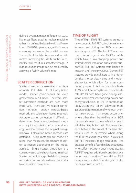
96 QUALIT Y CONTROL OF NUCLEAR MEDICINE INSTRUMENTATION AND PROTOCOL STANDARDISATION
CHAPTER 7
OP
TIMISA
TION
OF P
ET/CT —
A
CQ
UISITIO
N A
ND
REC
ON
STRU
CTIO
N
defined by a parameter in frequency space like most filters used in nuclear medicine; rather, it is defined by its full-width half-max-imum (FWHM) in pixel space, which is more commonly known as the spatial domain. The width of the filter is measured in milli-metres. Increasing the FWHM on the Gauss-ian filter will result in a smoother image. A high-resolution image can be produced by applying a FWHM value of 5 mm.
SCATTER CORRECTIONScatter correction is essential to achieve accurate PET data. In 3D acquisition modes, scatter coincidences are even greater than in 2D mode. Therefore, scat-ter correction methods are even more important. There are two scatter correc-tion methods: energy window-based methods and calculation-based methods. Accurate scatter correction is difficult to determine. Energy window-based meth-ods require acquisition of a second en-ergy window below the original energy window. Calculation-based methods are preferred. Such methods are modelled rather than measured, the amount of scat-ter correction depending on the model applied. Single scatter simulation is a currently used calculation-based method. Scatter correction is applied during image reconstruction and should take place prior to attenuation correction.
TIME OF FLIGHTTime of flight (ToF) PET systems are not a new concept. ToF PET coincidence imag-ing was used during the 1980s on exper-imental systems[12]. The first PET scanners used bismuth germinate (BGO) crystals, which have a low stopping power and limited spatial resolution and cannot sup-port ToF PET. ToF systems were limited to research until the early 2000s. Current PET systems provide scintillators with a higher density, shorter decay time and modern electronics which allow for faster com-puting power. Lutetium oxyorthosilicate (LSO) and lutetium-yttrium oxyorthosili-cate (LYSO) both have good timing reso-lution and increased stopping power and energy resolution. ToF PET is common on today’s scanners. ToF PET allows for more accurate determination of where an event has taken place. If an event occurs any-where other than the midline of an LOR, the crystal closer to the annihilation event will detect its photon first. The time differ-ence between the arrival of the two pho-tons is used to determine where along the LOR the event took place. As a result, ToF PET increases image resolution. The greatest benefit is found in larger patients, who suffer most from poor image quality. ToF PET requires additional considerations during reconstruction. The addition of ToF data prompts a shift from sinogram to list mode reconstruction[12].
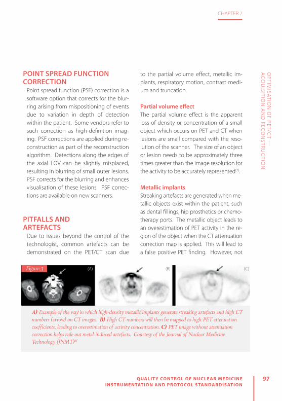
97
CHAPTER 7
QUALIT Y CONTROL OF NUCLEAR MEDICINE INSTRUMENTATION AND PROTOCOL STANDARDISATION
OP
TIMISA
TION
OF P
ET/CT —
A
CQ
UISITIO
N A
ND
REC
ON
STRU
CTIO
N
POINT SPREAD FUNCTION CORRECTION
Point spread function (PSF) correction is a software option that corrects for the blur-ring arising from mispositioning of events due to variation in depth of detection within the patient. Some vendors refer to such correction as high-definition imag-ing. PSF corrections are applied during re-construction as part of the reconstruction algorithm. Detections along the edges of the axial FOV can be slightly misplaced, resulting in blurring of small outer lesions. PSF corrects for the blurring and enhances visualisation of these lesions. PSF correc-tions are available on new scanners.
PITFALLS AND ARTEFACTS
Due to issues beyond the control of the technologist, common artefacts can be demonstrated on the PET/CT scan due
to the partial volume effect, metallic im-plants, respiratory motion, contrast medi-um and truncation.
Partial volume effectThe partial volume effect is the apparent loss of density or concentration of a small object which occurs on PET and CT when lesions are small compared with the reso-lution of the scanner. The size of an object or lesion needs to be approximately three times greater than the image resolution for the activity to be accurately represented[7].
Metallic implantsStreaking artefacts are generated when me-tallic objects exist within the patient, such as dental fillings, hip prosthetics or chemo-therapy ports. The metallic object leads to an overestimation of PET activity in the re-gion of the object when the CT attenuation correction map is applied. This will lead to a false positive PET finding. However, not
A) Example of the way in which high-density metallic implants generate streaking artefacts and high CT numbers (arrow) on CT images. B) High CT numbers will then be mapped to high PET attenuation coefficients, leading to overestimation of activity concentration. C) PET image without attenuation correction helps rule out metal-induced artefacts. Courtesy of the Journal of Nuclear Medicine Technology (JNMT)[1]
Figure 3 (A) (B) (C)

98 QUALIT Y CONTROL OF NUCLEAR MEDICINE INSTRUMENTATION AND PROTOCOL STANDARDISATION
CHAPTER 7
OP
TIMISA
TION
OF P
ET/CT —
A
CQ
UISITIO
N A
ND
REC
ON
STRU
CTIO
N
all metallic objects produce false positives. For example, in the case of hip prosthetics, the implants produce high CT numbers because of their high photon absorption. These implants will also attenuate the PET 511-keV photons. This results in no emis-sion data and demonstration of a cold area. When CT attenuation correction is per-formed, the PET images show diminished uptake in that area. In these cases, the non-attenuated PET images can be useful for interpretation of the study (Fig. 3).
Respiratory motionDue to the nature of the human body, re-spiratory motion is the most common arte-fact demonstrated on a PET/CT image. The artefact is due to the diff erence between the chest position on the PET image and the chest position on the CT image. The image resulting from a PET scan is an aver-age of many breathing cycles while the CT image is obtained at a single stage of one breathing cycle. To partially compensate for this possible artefact, the CT image can be obtained at mid-expiration, at mid-in-spiration or during shallow breathing. The image produced has a curvilinear cold area at the lung–diaphragm interface. The most critical impact of this artefact is on liv-er lesions. Because of this motion, a liver lesion may appear to be in the lung, simu-lating a lung nodule. This type of artefact is a misregistration of lesions. In these cases,
use of the CT image to defi ne the location of the lesion will help in interpretation. To minimise respiratory motion artefacts, the breathing procedure should be explained to the patient thoroughly before begin-ning the study (Fig. 4).
Contrast mediaAs previously mentioned, contrast agents can be administered in PET/CT studies. Contrast agents such as barium sulphate and iodine that are within the patient from a previous study can give rise to a false pos-
A 58-year-old man with colon cancer. A) Lesion at the dome of the liver is mislocalised to the right lung (arrow) because of respiratory motion. B) Image without attenuation correction shows that all lesions are confined to the liver. Courtesy of the Journal of Nuclear Medicine Technology (JNMT)[1]
Figure 4

99
CHAPTER 7
QUALIT Y CONTROL OF NUCLEAR MEDICINE INSTRUMENTATION AND PROTOCOL STANDARDISATION
OP
TIMISA
TION
OF P
ET/CT —
A
CQ
UISITIO
N A
ND
REC
ON
STRU
CTIO
N
itive finding on the PET image because they mimic metallic object artefacts. The higher the concentration of the contrast, the high-er the CT number, resulting in higher PET at-tenuation coefficients. This causes an over-estimation of the PET tracer uptake, which
is the reason for the false positive study. A technologist should be aware of whether the patient has had a previous study involv-ing use of contrast. In the case of prior con-trast use and presence of the resulting arte-fact, the non-attenuated PET images can be used for interpretation (Fig. 5).
TruncationTruncation artefacts occur because of the difference in size of the FOV between the CT and PET images. They are most com-
mon in larger patients or patients imaged with their arms down by their sides. When a patient extends beyond the CT FOV, the extended anatomy is truncated and not represented in the reconstructed CT im-age. This results in no attenuation correc-
tion values for the corresponding region. The consequence is a bias on the PET at-tenuation-corrected images, which under-estimate the SUV in the region in question. Truncation also produces streaking arte-facts at the edge of the CT image, resulting in an overestimation of the attenuation coefficients to be used to correct the PET data. To avoid this artefact, the patient should be positioned in the centre of the FOV and imaged with the arms above his or her head, when possible (Fig. 6).
A 61-year-old patient with lung cancer who ingested barium for an oesophagogram one day before PET/CT scan. A) Concentration of contrast medium in colon (arrow) is increased because of significant water reabsorption, shown on the CT image. B) High CT numbers of residual barium overcorrect attenuation of PET emission data and mimic increased 18F-FDG uptake on the PET image with CT attenuation correction. C) No increase in 18F-FDG uptake is seen on the image without attenuation correction. Courtesy of the Journal of Nuclear Medicine Technology (JNMT)[1]
Figure 5 (B)(A) (C)

100 QUALIT Y CONTROL OF NUCLEAR MEDICINE INSTRUMENTATION AND PROTOCOL STANDARDISATION
CHAPTER 7
OP
TIMISA
TION
OF P
ET/CT —
A
CQ
UISITIO
N A
ND
REC
ON
STRU
CTIO
N
A 54-year-old man with a history of metastatic melanoma (arrow). The CT image (A) appears truncated at the sides and biases the PET attenuation-corrected image (B). Courtesy of the Journal of Nuclear Medicine Technology (JNMT)[1]
Figure 6 (B)(A)

101
CHAPTER 7
QUALIT Y CONTROL OF NUCLEAR MEDICINE INSTRUMENTATION AND PROTOCOL STANDARDISATION
OP
TIMISA
TION
OF P
ET/CT —
A
CQ
UISITIO
N A
ND
REC
ON
STRU
CTIO
N
REFERENCES
1. Sureshbabu W, Mawlawi O. PET/CT imaging artifacts. J Nucl Med Technol 2005;33:156–161.
2. Boellaard R, O’Doherty MJ, Weber WA, Mottaghy FM, Lonsdale MN, Stroobants SG, et al. FDG PET and PET/CT: EANM procedure guidelines for tumour PET imaging: Version 1.0. Eur J Nucl Med Mol Imaging 2009;37:181–200.
3. Boellaard R, Delgado-Bolton R, Oyen WJG, Giam-marile F, Tatsch K, Eschner W, et al. FDG PET/CT: EANM procedure guidelines for tumour imaging: Version 2.0. Eur J Nucl Med Mol Imaging 2014;42:328–354.
4. The American College of Radiology. ACR–SPR practice parameter for performing FDG-PET/CT in oncology. 2016. https://www.acr.org/~/me-dia/71B746780F934F6D8A1BA5CCA5167EDB.pdf. Accessed January 12, 2017.
5. Townsend DW. Combined PET/CT: the historical per-spective. Semin Ultrasound CT MR 2008;29:232–235.
6. Hogg P, Testanera G, eds. Principles and practice of PET/CT. Part 1. A technologist’s guide. EANM; 2012. http://www.eanm.org/content-eanm/up-loads/2016/11/gl_Principles_and_Practice_of_PET-CT_Part_1.pdf. Accessed January 11, 2017.
7. Christian PE, Swanston NM. PET study guide. 2nd ed. Reston, VA: SNMMI; 2015.
8. Thie JA. Understanding the standardized uptake value, its methods, and implications for usage. J Nucl Med 2004;45:1431–1434.
9. Seeram E. Computed tomography: Physical princi-ples, clinical applications, and quality control. 3rd ed. United States: Elsevier Health Sciences; 2008.
10. Prekeges J. Nuclear medicine instrumentation. 2nd ed. Sudbury, MA: Jones & Bartlett; 2012.
11. Lartizien C, Kinahan P, Swensson R, Comtat C, Lin M, Villemagne V, Trébossen R. Evaluating image reconstruction methods for tumor detection in 3-dimensional whole-body PET oncology imaging. J Nucl Med 2003;44:276–290.
12. Vandenberghe S, Mikhaylova E, D’Hoe E, Mollet P, Karp JS. Recent developments in time-of-flight PET. EJNMMI Phys 2016;3:3.


8ACCREDITATION FOR CLINIC AL TRIALS: THE EANM EARL PROJEC T
by Giorgio Testanera and Michel de Groot
QU
ALIT
Y C
ON
TR
OL O
F NU
CLE
AR
ME
DIC
INE
INS
TR
UM
EN
TAT
ION
AN
D P
RO
TOC
OL S
TAN
DA
RD
ISA
TIO
N

104 QUALIT Y CONTROL OF NUCLEAR MEDICINE INSTRUMENTATION AND PROTOCOL STANDARDISATION
CHAPTER 8
AC
CR
EDITA
TION
FOR
CLIN
ICA
L TRIA
LS: TH
E EAN
M EA
RL P
RO
JECT
INTRODUCTIONMultiple research studies have shown the benefit of combined positron emission tomography (PET) and computed tomography (CT) in clinical decision making using 2-[18F]fluoro-2-deoxy-D-glucose (FDG) as the leading radiopharmaceutical for diagnosis, staging, prognosis and response monitoring. PET/CT has the ability to provide quantitative information through image analysis of the distribution of a wide variety of PET radiopharmaceuticals, including FDG, using standardised uptake values (SUVs).
Both quantification and the development of new and promising PET radiopharma-ceuticals have become more important in clinical decision making and improved quality of care for the individual patient[1, 2].
The use of FDG-PET as a surrogate tool for monitoring of therapy response offers better patient care by allowing individu-alisation of treatment and avoidance of ineffective treatments: surgery, radiation therapy or chemotherapy. Imaging bio-markers are of paramount importance, not only for patient evaluation but also for drug development.
QUANTITATIVE PET/CTQuantification in PET/CT can be defined as the use of a combination of methods to enhance image resolution, reduce im-age noise and perform data analysis, and use of the maximum standardised uptake value (SUVmax) can be considered as the standard quantitative method in practice. Assessment of cellular uptake is one of the
greatest tools for establishing the position of PET/CT as a state of the art modality in oncology patient care within the compet-itive environment of diagnostic imaging.
Owing to its widespread use in tumour response assessment studies, the SUV, de-fined as the activity concentration ratio in tissues, can be considered the measure to be used in order to standardise PET scans. Absolute SUV is used for definition of pa-tient eligibility, patient stratification and lesion selection, while relative SUV (per-centage changes from pre-treatment val-ues) can also be used to evaluate response to therapy. However, SUV measurements present uncertainties that may result in resistance to their use in clinical trials of cancer therapies. Possible causes of un-certainties are as follows[3]:
Technical factors » Relative calibration between the PET scanner and dose calibrator (10%)
» Residual activity in the syringe (5%) » Incorrect synchronisation of clocks (10%)

105
CHAPTER 8
QUALIT Y CONTROL OF NUCLEAR MEDICINE INSTRUMENTATION AND PROTOCOL STANDARDISATION
AC
CR
EDITA
TION
FOR
CLIN
ICA
L TRIA
LS: TH
E EAN
M EA
RL P
RO
JECT
» Injection vs. calibration time (10%) » Quality of administration (50%)
Physics-related factors » Scan acquisition parameters (15%) » Image reconstruction parameters (30%) » Use of contrast agents (15%) » ROI (50%)
Biological factors » Uptake period (15%) » Patient motion and breathing (30%) » Blood glucose levels (15%)
Furthermore, the variability in methodolo-gy across centres hinders the exchange of SUV measurements. Therefore, standardi-sation of FDG-PET whole-body procedures is essential in multicentre trials. Accord-ingly, the nuclear medicine community is working to achieve standardisation of PET/CT imaging and to improve the quality of the images generated, both in clinical rou-tine and in clinical trials [1, 2].
EARLIn 2010, the European Association of Nu-clear Medicine (EANM) initiated a pro-gramme for the accreditation of PET/CT scanners using FDG in order to support compliance with requirements regarding quality control (QC) and quality assurance of PET/CT systems. The programme, run
within the scope of EANM Research Lim-ited (EARL) activities, was originally based on FDG-PET and PET/CT: EANM procedure guidelines for tumour PET imaging: version 1.0, published in the European Journal of Nuclear Medicine and Molecular Imaging (EJNMMI). This widely accepted guideline, revised to version 2.0 in 2014, aims at har-monising quantification in multicentre studies and providing a minimum stan-dard for the acquisition and interpretation of PET and PET/CT scans obtained with FDG. The guideline specifically addresses patient preparation, dosage of FDG as a function of scanner model, patient weight and scan duration, data acquisition, image reconstruction, data analysis and QC pro-cedures[2, 4].
The FDG-PET/CT accreditation ensures harmonised quantitative performance of PET/CT systems within a multicentre setting through the standardisation of ac-quisition and processing of PET/CT scans. This rigorous harmonisation of imaging systems enables PET/CT sites to compare, exchange and combine FDG-PET/CT find-ings as data are collected and processed. SUVs can also be reliably used owing to the resultant reduction in inter- and in-tra-institute variability. The standardisation achieved by the accreditation programme relates to imaging procedures and meth-odology, including patient preparation,

106 QUALIT Y CONTROL OF NUCLEAR MEDICINE INSTRUMENTATION AND PROTOCOL STANDARDISATION
CHAPTER 8
AC
CR
EDITA
TION
FOR
CLIN
ICA
L TRIA
LS: TH
E EAN
M EA
RL P
RO
JECT
scan acquisition and image processing and analysis, which is of the utmost im-portance for quality assurance in daily clinical practice as well as in multicentre trials[2].
COLLABORATION WITH OTHER INSTITUTIONS
The EARL FDG-PET/CT accreditation pro-gramme is strongly supported by the European Organisation for Research and Treatment of Cancer Imaging Group (EO-RTC-IG), which was founded in 2009 to en-sure standardisation of image acquisition and quality assurance for EORTC clinical trials with regard to CT, PET, magnetic res-onance imaging (MRI) and other imaging modalities as they become available[5]. EANM/EARL and the International Atom-ic Energy Agency (IAEA) are also working together with respect to quality stan-dards in nuclear medicine. EANM/EARL is aware of the different harmonisation and standardisation efforts regarding PET/CT worldwide and is eager to contribute to a possible alignment of accreditation programmes. To this end, discussions are being held with the Society of Nuclear Medicine and Molecular Imaging (SNMMI) Clinical Trials Network (CTN).
Furthermore, the Japanese Society of Nuclear Medicine (JSNM) has adopted the basis of the EARL accreditation pro-
gramme. The Italian Lymphoma Founda-tion (FIL), Lymphoma Study Association (LYSA) and GELA (Groupe d’Etude des Lymphomes de l’Adulte, i.e. Adult Lym-phoma Study Group) are further groups that have taken the EANM imaging guide-line as the basis for PET/CT QC within their studies. The Society of Nuclear Medicine, India (SNMI) and the Brazilian Society of Nuclear Medicine (Sociedade Brasileira de Medicina Nuclear/SBMN) have also expressed great interest in the EARL FDG-PET/CT accreditation programme.
The EANM imaging guideline is wide-ly accepted and is also well represented within the draft of the Uniform Protocols for Imaging in Clinical Trials (UPICT), es-tablished by the Quantitative Imaging Biomarkers Alliance (QIBA).
MULTICENTRE CLINICAL TRIALSThe goal of the EARL FDG-PET/CT ac-creditation programme is to enhance the quality standard of PET/CT investigations for both daily use and multicentre studies. FDG-PET/CT accreditation ensures similar performance of PET/CT systems within a multicentre setting through the harmoni-sation of acquisition and processing of PET/CT scans. Centres can compare, exchange and combine FDG-PET/CT findings, includ-ing SUVs, since data are collected and pro-cessed in a standardised manner[2].

107
CHAPTER 8
QUALIT Y CONTROL OF NUCLEAR MEDICINE INSTRUMENTATION AND PROTOCOL STANDARDISATION
AC
CR
EDITA
TION
FOR
CLIN
ICA
L TRIA
LS: TH
E EAN
M EA
RL P
RO
JECT
In order to ensure that data can be ex-changed between centres participating in a multicentre trial organised in collabora-tion with EARL, it is essential that all PET/CT systems used in the trial are accredited by EARL. Furthermore, all centres should be required to apply the EARL-approved parameter settings (used for processing of the QC phantom images) for the recon-struction of imaging during the course of the trial. The sites can apply additional re-constructions for other purposes, local use or diagnostic interpretations. The EANM provides recommendations for acquisition times per bed position in combination with dosage per kg patient weight for var-ious types of PET/CT system in the EANM imaging guideline[2].
An up-to-date list of accredited centres participating in the EARL FDG-PET/CT ac-creditation programme, also known as the Centres of Excellence (CoE), can be found via the EARL website.
ACCREDITATION BENEFITSThe current established and scientifical-ly validated FDG-PET/CT accreditation programme provides independent qual-ity control/assurance within multicentre clinical trials and specifically addresses the needs of the pharmaceutical industry regarding harmonisation and standardi-
sation. Centres seeking accreditation also benefit from:
» EARL’s knowledge, which is based on the contributions of worldwide-recognised imaging experts, with a global leading role in PET/CT research, who provide ad-vice within the programme and monitor its development.
» Imaging results that can be compared, exchanged and combined, since the prerequisite for evaluation of imaging re-sults within preclinical and clinical (mul-ticentre) trials is comparable scanner performance across multiple sites (re-duction of inter- and intra-institute vari-ability in SUV results; provision of lower/upper limits of recovery coefficients; cal-ibration factor within ±10%).
» Accurate, reproducible and quantitative assessment enabled through standard-isation of methodology, including pa-tient preparation, scan acquisition, im-age processing and analysis.
» Reliable and quantitative imaging biomark-er results generated within multicentre clinical trials, leading to an enhanced outcome (e.g. information on biological/pathological processes and response to therapeutic intervention) and thus ac-celerating compound development and approval by the regulatory agencies and lowering costs in the long run[4].
» An exploratory further optimisation, presently being evaluated by EARL. This

108 QUALIT Y CONTROL OF NUCLEAR MEDICINE INSTRUMENTATION AND PROTOCOL STANDARDISATION
CHAPTER 8
AC
CR
EDITA
TION
FOR
CLIN
ICA
L TRIA
LS: TH
E EAN
M EA
RL P
RO
JECT
procedure would allow lowering of the administered FDG activity for PET/CT systems with higher sensitivity or improved performance using new en-hanced technology (e.g. better time-of-flight performance, continuous bed motion or extended axial field of view, i.e. length of bed position).
PROCESSES INVOLVED IN ACCREDITATION
Sites which are seeking EARL FDG-PET/CT accreditation for the first time need to pass through the initial procedure. This proce-dure includes submission of the online questionnaire and signing of the statement and signet policy. Additionally, sites are asked to perform and submit QC data with-in the subsequent 3 weeks. For this pur-pose, sites have to perform calibration QC measurements using a cylindrical calibra-tion phantom and image quality QC mea-surements using a NEMA NU2-2001/2007 image quality phantom and to submit on-line the image data in DICOM format and the results to EARL. A detailed step-by-step procedure is published in the FDG-PET/CT accreditation manual to assist sites in ade-quately performing these measurements. After submission and independent review of the results by EARL, the site is granted EARL FDG-PET/CT accreditation, assuming the results meet EARL requirements [2, 6].
After initial accreditation, centres are requested at fixed quarterly intervals to meet the standard requirements, as de-scribed in the most recent versions of the EANM imaging guideline and manual, in order to retain their accreditation. Failure to adhere to the deadlines for submission may lead to EARL putting a centre’s ac-creditation on hold. The documentation in the initial accreditation procedure needs to be submitted only once, whereas the QC measurements and documents need to be regularly performed and submitted to retain the accreditation. An update of the online questionnaire in the first quar-ter of each year is a prerequisite for sub-mission of the QC documents[2, 6].
SPECIFIC QUALITY CONTROLS
Calibration QC Calibration QC measurements should be performed for initial accreditation and have to be repeated every 3 months. The aim is to verify that the average activi-ty concentration and/or SUV within the phantom is within 10% of the expected value. For this purpose a cylindrical cali-bration phantom of any dimension but with a precisely known volume is required (it is preferable to obtain the phantom via the manufacturer, ensuring that it is spe-cific for the used PET/CT model; if this is

109
CHAPTER 8
QUALIT Y CONTROL OF NUCLEAR MEDICINE INSTRUMENTATION AND PROTOCOL STANDARDISATION
AC
CR
EDITA
TION
FOR
CLIN
ICA
L TRIA
LS: TH
E EAN
M EA
RL P
RO
JECT
not possible, the phantom should be 20 cm in diameter and 20–30 cm long) (Fig. 11). The process of cross-calibration de-termines the correct and direct (cross- or relative) calibration of the PET/CT system with the institution’s own dose calibrator or against another one which is used to determine patient-specifi c FDG activities[4].
All relevant information on the standard operating procedure (SOP) needs to be recorded accurately, including the exact phantom volume, the scanner hardware and software, the exact doses and the time of performance of every step.
It is fi rst necessary to prepare a 5- to 10-ml syringe with an activity of approximate-
ly 70 MBq (65–75 MBq) FDG. The FDG ac-tivity is dispensed into the phantom when it is completely full with water, ensuring that all the activity is in the phantom by fl ushing the syringe a few times. The phan-tom must then be vigorously shaken in order to homogenise the distribution of the activity.
After positioning the phantom in the centre of the gantry, a PET/CT scan consist-ing of at least two PET bed positions needs to be acquired. PET/CT scan acquisition and reconstruction should be performed identically to patient studies as prescribed in the clinical protocol. However, for statis-tical reasons somewhat longer emission
Figure 1
Calibration QC setup (© Giorgio Testanera and Fabio Provenzano, Humanitas Research Hospital)

110 QUALIT Y CONTROL OF NUCLEAR MEDICINE INSTRUMENTATION AND PROTOCOL STANDARDISATION
CHAPTER 8
AC
CR
EDITA
TION
FOR
CLIN
ICA
L TRIA
LS: TH
E EAN
M EA
RL P
RO
JECT
times (e.g. 5–10 min per bed position) are recommended, with inclusion of a standard transmission scan or (low-dose) CT for the purpose of attenuation correction.
Reconstructions should be per-formed with corrections for attenuation, scatter, normalisation, decay and dead time, i.e. all corrections necessary for quantifi cation [6].
Image quality QC Although correct cross-calibration is guar-anteed using the calibration procedure described above, diff erences in SUV quan-tifi cation may still occur between centres as a result of diff erences in the reconstruc-tion and data analysis methodology. Con-sequently, an image quality QC procedure has been developed:
» to determine/check the correctness of a calibration and quantifi cation using a non-cylindrical (calibration) phantom containing a set of high-contrast spher-ical objects
» to measure standardised “activity concentration or SUV recovery coef-ficients” as a function of sphere (tu-mour) size
The main aim of this procedure is to guarantee comparable quantitative PET/CT system performance with respect to SUV recovery and quantifi cation. Image quality QC measurements should be performed for initial accreditation and thereafter have to be performed and submitted every year. These measure-ments are based on calculation of SUV
Figure 2
Typical calibration QC images
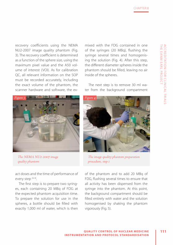
111
CHAPTER 8
QUALIT Y CONTROL OF NUCLEAR MEDICINE INSTRUMENTATION AND PROTOCOL STANDARDISATION
AC
CR
EDITA
TION
FOR
CLIN
ICA
L TRIA
LS: TH
E EAN
M EA
RL P
RO
JECT
recovery coeffi cients using the NEMA NU2-2007 image quality phantom (Fig. 3). The recovery coeffi cient is determined as a function of the sphere size, using the maximum pixel value and the A50 vol-ume of interest (VOI). As for calibration QC, all relevant information on the SOP must be recorded accurately, including the exact volume of the phantom, the scanner hardware and software, the ex-
act doses and the time of performance of every step [4, 6].
The fi rst step is to prepare two syring-es, each containing 20 MBq of FDG at the expected phantom acquisition time. To prepare the solution for use in the spheres, a bottle should be fi lled with exactly 1,000 ml of water, which is then
mixed with the FDG contained in one of the syringes (20 MBq), fl ushing the syringe several times and homogenis-ing the solution (Fig. 4). After this step, the diff erent diameter spheres inside the phantom should be fi lled, leaving no air inside of the spheres.
The next step is to remove 30 ml wa-ter from the background compartment
of the phantom and to add 20 MBq of FDG, fl ushing several times to ensure that all activity has been dispensed from the syringe into the phantom. At this point, the background compartment should be fi lled entirely with water and the solution homogenised by shaking the phantom vigorously (Fig. 5).
Figure 3
The NEMA NU2-2007 image quality phantom
Figure 4
The image quality phantom preparation procedure, step 1

112 QUALIT Y CONTROL OF NUCLEAR MEDICINE INSTRUMENTATION AND PROTOCOL STANDARDISATION
CHAPTER 8
AC
CR
EDITA
TION
FOR
CLIN
ICA
L TRIA
LS: TH
E EAN
M EA
RL P
RO
JECT
It is now possible to acquire a routine quantitative whole-body FDG-PET scan of at least two PET bed positions (at least 5 min per bed position), covering the entire phantom, with use of standard acquisition parameters as specifi ed in the guidelines (Fig. 6). It is important to position the phantom so that the spheres are located at the centre of the axial fi eld of view.
Reconstructions should be performed with corrections for attenuation, scatter, normalisation, decay and dead time, i.e. all corrections necessary for quantifi cation (Fig. 7)[4].
GENERAL SUGGESTIONSAll procedures require great accuracy, and various pitfalls are possible:
» Equipment used in obtaining EARL ac-creditation (e.g. dose calibrator, PET and/or CT system, clocks) should be able to perform accurately and precisely within operational tolerances; typically this means that equipment is calibrated and periodically serviced.
» All clocks involved in the procedure (dose calibrator, PET or PET/CT system) should be synchronised with the offi -cial local time to within 1 min in order to prevent unnecessary deviations in activities.
» Residual activity within the syringe will result in incorrect verifi cation of PET or PET/CT system calibration; therefore post-injection measurement of activity in the syringe is advisable.
» Accurate quantifi cation in PET or PET/CT can be threatened by high dead time or
Figure 5
The image quality phantom preparation procedure, step 2
Figure 6
The image quality phantom scanning procedure

113
CHAPTER 8
QUALIT Y CONTROL OF NUCLEAR MEDICINE INSTRUMENTATION AND PROTOCOL STANDARDISATION
AC
CR
EDITA
TION
FOR
CLIN
ICA
L TRIA
LS: TH
E EAN
M EA
RL P
RO
JECT
random fractions. To prevent this, it is important to check whether the count rates exceed the limits of the scanner acquisition system. If count rates do ex-ceed these limits, it is suggested that a QC with a lower FDG activity should be performed, perhaps with preparation of the phantom a couple of hours in ad-vance to allow for radioactive decay.
» The use of FDG with high activity concen-trations can result in inaccurate dosing; in these cases (a portion of ) the stock solu-tion should be diluted to clinically used activity concentrations before use.
Additionally, sites should always be aware that accreditation is granted for a
specifi c system (manufacturer and mod-el) and that EARL needs to be informed if a PET/CT system has been replaced and/or upgraded (since this may have conse-quences for the current accreditation) or if a centre wishes to obtain accreditation for an additional PET/CT system [2, 3].
DATA ANALYSISThe dedicated software that has been de-veloped to ensure standardised analysis of QC documents allows the automatic im-port of data from the scan report forms to the analysis tool, which minimises sources of error and further standardises and fa-cilitates work procedures. The calibration
Figure 7
Typical image quality phantom images

114 QUALIT Y CONTROL OF NUCLEAR MEDICINE INSTRUMENTATION AND PROTOCOL STANDARDISATION
CHAPTER 8
AC
CR
EDITA
TION
FOR
CLIN
ICA
L TRIA
LS: TH
E EAN
M EA
RL P
RO
JECT
Image quality results verification with dedicated software
Figure 8

115
CHAPTER 8
QUALIT Y CONTROL OF NUCLEAR MEDICINE INSTRUMENTATION AND PROTOCOL STANDARDISATION
AC
CR
EDITA
TION
FOR
CLIN
ICA
L TRIA
LS: TH
E EAN
M EA
RL P
RO
JECT
QC phantom measurements reveals the cross-calibration factor between the PET/CT system and the dose calibrator. This fac-tor needs to be within ±10% from 1. The image quality QC phantom measurements are analysed in order to determine the background calibration factor by using sev-eral VOIs placed in the uniform background compartment. The maximum allowable calibration deviation is again ±10% from 1. Additionally, the SUV recovery coefficients are calculated for each sphere (Fig. 8). A cold spot recovery using a central insert to verify the accuracy of scatter correction is also performed. The software automatically compares the results of both QC phantom analyses with the EARL specifications [2].
TECHNOLOGIST’S ROLE AND DAILY PRACTICE
In PET centres, technologists have the ma-jor role of acquiring images with PET and PET/CT scanners and ensuring that the ac-quired images meet the quality standards established by departmental criteria. The first step in assuring that quantitative im-aging is accurate is compliance with all QC procedures stipulated for the PET scanner by national regulations, the vendor and local regulations. Working at an accred-ited site for clinical trials implies not only greater accuracy in standard daily practice but also a different mindset. Involvement
in the accreditation procedure may help technologists to develop this new mindset and to raise operating standards. There is a great ongoing debate in Europe regard-ing the basic competencies and advanced practice of nuclear medicine technolo-gists. A consensus document[7] has distin-guished two levels, as follows:
Entry level » A competence and skill set that is con-sidered necessary to ensure that nuclear medicine procedures are conducted to an appropriate level
» This competence and skill set would be acquired during basic training/formative professional education
Advanced practice » A competence and skill set that is ac-quired after basic training
» The competence and skill set would be at a higher cognitive and clinical level than basic training/formative profession-al education
» The competence and skill set would seek to improve patient care and man-agement
» The competence and skill set would seek to offer clinical career progression opportunities
It is true that the technologist’s role in EARL accreditation can be considered a basic

116 QUALIT Y CONTROL OF NUCLEAR MEDICINE INSTRUMENTATION AND PROTOCOL STANDARDISATION
CHAPTER 8
AC
CR
EDITA
TION
FOR
CLIN
ICA
L TRIA
LS: TH
E EAN
M EA
RL P
RO
JECT
competency, since it mainly relates to QC, but meeting the high-quality standards required surely pushes technologists to improve their working skills. This improve-ment, often requiring a completely new skill set, can be considered at the higher cognitive level and fosters improvement of patient care and departmental efficien-cy. Therefore, the role of the technologist can be considered to be either basic or advanced, depending on whether he or she is taking the lead in the process, and can be a good starting point in further
developing advanced practice in nuclear medicine departments.
Useful linkshttp://earl.eanm.org/cms/website.php (EARL website – home)
Copyright InformationAll figures are the property of Giorgio Tes-tanera and Fabio Provenzano, Humanitas Research Hospital
REFERENCES
1. Boellaard R, Oyen WJG, Hoekstra CJ, Hoekstra OS, Visser EP, Willemsen AT, et al. The Netherlands pro-tocol for standardisation and quantification of FDG whole body PET studies in multi-centre trials. Eur J Nucl Med Mol Imaging 2008;35:2320–2333.
2. Ettinger S, Testanera G, Sera T, Boellaard R, Verzijlber-gen F, Chiti A. Quality visits: The EANM/EARL FDG-PET/CT accreditation programme. In: Glaudemans AWJM, Medema J, van Zanten AK, Dierckx RAJO, Ahaus CTBK, eds. Quality in nuclear medicine. Heidelberg Berlin New York: Springer International Publishing; 2017:415–427.
3. Boellard R. Standards for PET image acquisition and quantitative data analysis. J Nucl Med 2009;50 Suppl 1:11S–20S.
4. Boellaard R, Delgado-Bolton R, Oyen WJG, Giam-marile F, Tatsch K, Eschner W. FDG PET/CT: EANM procedure guidelines for tumour imaging: version 2.0. Eur J Nucl Med Mol Imaging 2015;42:328–354.
5. DeSouza N, Hoekstra OS, Nestle U, Stroobants S, Boellaard R, Schaefer-Prokop C, et al. EORTC Imaging Group. Eur J Cancer Suppl 2012;10:82–7.
6. Manual for EARL FDG-PET/CT Accreditation, version 2.1 (April 2013). EARL, EANM Research Ltd.
7. Waterstram-Rich K, Hogg P, Testanera G, Medvedec H, Dennan SE, Knapp W, et al. Euro-American discus-sion document on entry-level and advance practice. Nucl Med Technol 2011;39:240–248.
FURTHER SUGGESTED READING
» Flyer. EARL FDG-PET/CT Accreditation (March 2013). EARL, EANM Research Ltd.
» Tatsch K. Standardisation and harmonisation boost the credibility of nuclear medicine procedures. Eur J Nucl Med Mol Imaging 2012;39:186–7.

117
CHAPTER 8
QUALIT Y CONTROL OF NUCLEAR MEDICINE INSTRUMENTATION AND PROTOCOL STANDARDISATION
AC
CR
EDITA
TION
FOR
CLIN
ICA
L TRIA
LS: TH
E EAN
M EA
RL P
RO
JECT9R ADIONUCLIDE
C ALIBR ATOR
by Aljaz Socan
QU
ALIT
Y C
ON
TR
OL O
F NU
CLE
AR
ME
DIC
INE
INS
TR
UM
EN
TAT
ION
AN
D P
RO
TOC
OL S
TAN
DA
RD
ISA
TIO
N
118 QUALIT Y CONTROL OF NUCLEAR MEDICINE INSTRUMENTATION AND PROTOCOL STANDARDISATION
CHAPTER 9
RA
DIO
NU
CLID
E CA
LIBR
ATO
R
INTRODUCTIONWhen undertaking any practices involving the human administration of a radiopharmaceutical, it is essential to use sensitive instrumentation for the detection and measurement of radioactive emissions. This allows a practical measure for dispensing the low amounts required for diagnostic uses and an accurate measure of therapeutic levels of radioactivity. This is also especially important for experimental work contributing to scientific knowledge relating radiation doses to biological effects.
When radiations from a radioactive mate-rial pass through matter, they interact with atoms and molecules and transfer energy to them. The transfer of energy has two effects: ionisation and excitation. Ionisa-tion occurs when the energy transferred is sufficient to cause an orbital electron to be stripped away from its parent atom or molecule, thus creating an ion pair (a neg-atively charged electron and a positively charged atom or molecule). Excitation oc-curs when electrons are perturbed from their normal arrangement in an atom or molecule, thus creating an atom or mol-ecule in an excited state. Both of these processes are involved in the detection of radiation events; however, ionisation is the primary event, and hence the term ionising radiation is frequently used when referring to the emissions from radioactive material[1].
BASIC PRINCIPLESMost gas-filled detectors belong to a class of detectors called ionisation detectors
(ionisation chambers). These detectors respond to radiation by means of ionisa-tion-induced electrical currents.
A volume of gas is contained between two electrodes having a voltage differ-ence (and thus an electric field) between them. The negative electrode is called the cathode, the positive electrode the anode (Fig. 1). Under normal circumstances, the gas is an insulator and no electrical current flows between the electrodes. However, radiation passing through the gas causes ionisation, both direct ionisation from the incident radiation and secondary ionisa-tion from delta rays [1]. Gas-filled detectors include ionisation chambers, proportional counters and Geiger-Müller (GM) count-ers. The use of these detectors in nuclear medicine is somewhat limited because their stopping power and detection ef-ficiency for X-rays and gamma rays are quite low; however, they find some use for applications in which detection efficiency is not a major factor and for detection and measurement of non-penetrating, parti-cle-type radiations [1].

119
CHAPTER 9
QUALIT Y CONTROL OF NUCLEAR MEDICINE INSTRUMENTATION AND PROTOCOL STANDARDISATION
RA
DIO
NU
CLID
E CA
LIBR
ATO
R
The electrons produced by ionisation are attracted to the positive electrode and the ionised atoms to the negative electrode, causing a momentary flow of a small amount of electrical current.
For maximum efficiency of operation, the voltage between the electrodes must be sufficient to ensure complete collec-tion of ions and electrons produced by ra-diation within the chamber. If the voltage is too low, some of the ions and electrons simply recombine with one another with-out contributing to electrical current flow (recombination region)[1].
As the voltage increases there is less recombination and the response (electri-
cal current) increases. When the voltage becomes sufficient to cause complete collection of all of the charges produced, the saturation region begins. The voltage at which the saturation region begins is called the saturation voltage (Vs, typically Vs ≈ 50–300 V). Ionisation chambers are operated at voltages in the saturation region (Fig. 2). This ensures a maximum response to radiation and also that the response will be relatively insensitive to instabilities in the voltage applied to the electrodes. The amount of electrical charge current released in an ionisation chamber by a single ionising radiation event is very small[1].
Basic principles of a gas-filled detector. Electrical charge liberated by ionising radiation is collected by positive (anode) and negative (cathode) electrodes. (Adopted from [1])
Figure 5

120 QUALIT Y CONTROL OF NUCLEAR MEDICINE INSTRUMENTATION AND PROTOCOL STANDARDISATION
CHAPTER 9
RA
DIO
NU
CLID
E CA
LIBR
ATO
R
Because of the small amount of electri-cal charge or current involved, ionisation chambers generally are not used to record or count individual radiation events. In-stead, the total amount of current passing through the chamber caused by a beam of radiation is measured. Alternatively, the electrical charge released in the chamber by the radiation beam may be collected
and measured. Small amounts of electrical current are measured using sensitive cur-rent-measuring devices called electrome-ters[1].
RADIONUCLIDE CALIBRATORA radionuclide calibrator is a device con-sisting of an ionisation chamber and an
Voltage response curve (charge collected vs. voltage applied to the electrodes) for a typical ionisation chamber. In usual operation, applied voltage exceeds saturation voltage Vs to ensure complete collection of liberated charge. (Adopted from [1])
Figure 2

121
CHAPTER 9
QUALIT Y CONTROL OF NUCLEAR MEDICINE INSTRUMENTATION AND PROTOCOL STANDARDISATION
RA
DIO
NU
CLID
E CA
LIBR
ATO
R
electrometer (Fig. 3). Unlike other types of ionisation chamber, radionuclide cal-ibrators employ sealed and pressurised chambers filled with argon gas. This elim-inates the effect of changing barometric pressure on output readings. Ionisation chamber radionuclide calibrators assay the total amount of activity present by measuring the total amount of ionisation produced by the sample. Radionuclide calibrators typically are calibrated to read directly in units of activity (Bq or Ci), with switches to set the display for different radionuclides. They are used for assaying relatively large quantities (i.e. MBq range) of gamma ray-emitting radioactivity too
large for assay with NaI(Tl) detector sys-tems.
Because ionisation chambers have no inherent ability for energy discrimination, they cannot be used to select different gamma ray energies for measurement, as is possible with detectors having pulse-height analysis capabilities. An approach that is used to distinguish low-energy from high-energy gamma ray emitters (e.g. 99mTc vs. 99Mo) is to measure the sam-ple with and without a few millimetres of lead shielding around the source (Fig. 4). Effectively, only the activity of the high-en-ergy emitter is recorded with the shielding
Schematic view of radionuclide calibrator. (Adopted from [6])
Figure 3

122 QUALIT Y CONTROL OF NUCLEAR MEDICINE INSTRUMENTATION AND PROTOCOL STANDARDISATION
CHAPTER 9
RA
DIO
NU
CLID
E CA
LIBR
ATO
R
in place, whereas the total activity of both emitters is recorded with the shielding ab-sent. This technique can be used to detect tens of kBq quantities of 99Mo in the pres-ence of tens or even hundreds of MBq of 99mTc [1].
As with the NaI(Tl) well counter, radio-nuclide calibrators are subject to sample volume eff ects (the fraction of gamma rays escaping through the hole at the end of the well depends on the position of the source in the well: it is about 7% if the source is near the bottom of the well but increases to 50% if it is near the top) and the geometric effi ciency of a well
counter depends on sample positioning[1]. If a small volume of radioactive solution of constant activity in a test tube is diluted progressively by adding water to it, the counting rate recorded from the sample in a standard well detector progressively decreases, even though the total activity in the sample remains constant. In es-sence, the geometric effi ciency for the sample decreases as portions of the ac-tivity are displaced to the top of the well. If the volume of a sample is increased by adding radioactive solution at a constant concentration, the counting rate fi rst in-creases linearly with sample volume (or activity) but the proportionality is lost as the volume approaches and then exceeds the top of the well. Eventually there is little change with increasing sample volume, although the total activity is increasing. For example, an increase in sample vol-ume in a standard test tube from 7 to 8 mL, i.e. a 14% increase in volume, increases the counting rate by only about 1%[1]. Thus the sample volume has signifi cant eff ects on the counting rate with well counters. For the stated reasons, sample volumes should be the same when comparing two samples. A technique applicable when adequate sample volumes are available is to use identical test tubes for all samples and to fi ll them such that the volume of activity inside the well itself does not diff er between samples.
Figure 4
99Mo breakthrough test lead shield (“radionuclide purity testing”)

123
CHAPTER 9
QUALIT Y CONTROL OF NUCLEAR MEDICINE INSTRUMENTATION AND PROTOCOL STANDARDISATION
RA
DIO
NU
CLID
E CA
LIBR
ATO
R
Absorption of gamma rays within the sample volume or by the walls of the test tube is not a major factor except when low-energy sources, such as 125I (27–35 keV), are counted. Identical test tubes and carefully prepared samples of equal volume should be used when comparing samples of these radionuclides[1].
The discussed effects should be inves-tigated experimentally when a new dose calibrator is acquired (acceptance testing), so that correction factors can be applied in its use, if necessary. For example, a quantity of activity can be measured in a very small volume (e.g. 0.1 mL in a 1-mL syringe). Activity can be diluted progres-sively afterwards to larger volumes in larger syringes and then in beakers, and so forth, to determine the amount by which the instrument reading changes with the sample volume[1]. Another pa-rameter worth evaluating is linearity of response versus sample activity; this may be determined conveniently by recording the reading for a 99mTc source of moder-ately high activity (e.g. 1 GBq, or whatev-er is the approximate maximum amount of activity that the dose calibrator will be used to assay) and then recording the readings during a 24- to 48-h period (four to eight half-lives) to determine whether they follow the expected decay curve for 99mTc. Deviations from the expected decay curve may indicate instrument electronic
non-linearities requiring adjustment or correction of readings. In applying this technique, it is necessary to correct for 99Mo contamination using the shielding technique, especially after several 99mTc half-lives have elapsed[1].
QUALITY ASSURANCE OF RADIONUCLIDE CALIBRATORS
For radionuclide calibrator installation, op-eration and maintenance, the manufactur-er’s operating manual should be followed. Only authorised personnel should operate the calibrator, and up-to-date instructions on the operation and maintenance of equipment should be readily available for reference and use. The radionuclide cali-brator should be placed on a solid, vibra-tion-free base and, as recommended by the manufacturer, operated at a relatively constant temperature and humidity and away from direct sunlight and any room heater or air conditioner. The area should not be affected by high-activity sources and additional shielding may be required for background reduction and/or person-nel exposure reduction [2].
Radionuclide calibrators may be locat-ed within laminar airflow workbenches or isolators to facilitate the compounding of sterile radiopharmaceutical preparations. Since all surfaces in the aseptic processing area require frequent cleaning and disin-

124 QUALIT Y CONTROL OF NUCLEAR MEDICINE INSTRUMENTATION AND PROTOCOL STANDARDISATION
CHAPTER 9
RA
DIO
NU
CLID
E CA
LIBR
ATO
R
fection, the radionuclide calibrator must be able to withstand frequent cleaning and disinfection with a variety of agents.
Extreme caution must be exercised to avoid damaging the radionuclide calibra-tor chamber and readout unit(s) when using cleaning and disinfection agents. The surfaces of chamber plastic liners and plastic dippers in the aseptic processing area must be cleaned and disinfected by appropriate means, such as wiping with a sterile 70% isopropyl alcohol-dampened cloth. Readout units may also be protect-ed with plastic covers that can be disin-fected frequently with sterile 70% isopro-pyl alcohol wipes[2].
Acceptance testing The International Commission on Ra-diological Protection (ICRP) defines an acceptance test as a “test carried out at the request and with the participation of the user or his representative to ascertain by determination of proper performance parameters that the instrument meets the specifications claimed by the vendor”. The ICRP recommends that an accep-tance test be carried out at the time of installation and when appropriate after a major service. In addition to ascertaining that the radionuclide calibrator meets the vendor specifications, test or reference data are obtained at acceptance testing and used for comparison with future rou-
tine tests[3]. The most thorough assess-ment of calibrator performance occurs at acceptance testing. Routine perfor-mance testing includes most of the same measurements. At acceptance testing or before first use, calibration settings for radionuclides in source geometries oth-er than those provided by the calibrator manufacturers must be determined if the potential assay uncertainty is unaccept-able (greater than 5%) [2–4]. Radiopharma-ceutical manufacturers and commercial nuclear pharmacies should be required to provide dosages whose assays are ac-curate to within ±5%. These dosages can be used to calibrate facility calibrators for the respective source geometries. At ac-ceptance testing or before first use, those individuals who will use the radionuclide calibrator should be instructed in calibra-tor operation, maintenance and quality control as appropriate. Instruction should include reading and comprehending the manufacturer’s operating manual[2].
Routine QC testsRoutine quality control (QC) tests are re-peated at specific intervals to establish and document changes from the initial performance of the radionuclide calibra-tor established at acceptance testing. The overall objective of performance testing is to assure the continued accuracy of the dosage assays[2].

125
CHAPTER 9
QUALIT Y CONTROL OF NUCLEAR MEDICINE INSTRUMENTATION AND PROTOCOL STANDARDISATION
RA
DIO
NU
CLID
E CA
LIBR
ATO
R
The tests recommended by EANM Phys-ics Committee and the EANM Working Group on Nuclear Medicine Instrumenta-tion Quality Control[5] are as follows and summarised in Table 1:
» Physical inspection » High voltage » Clock accuracy » Zero adjustment » Background counts/contamination check » Constancy (check source, relative response) » Stability » Accuracy test » Linearity
Physical inspection Check the calibrator and source holders for damage. Damaged source holders should be repaired or replaced. Check the display screen for proper operation and the console for keypad damage or damage to or malfunction of any push-buttons/switches/dials. Check to assure that the chamber liner is in place and that small items (e.g. needle caps) have not fallen into the well.
High voltage Test the high voltage and compare the result with the manufacturer’s tolerances in accordance with the instructions in the operator’s manual. Constant and correct operating voltage is essential for accurate activity measurement.
Clock accuracy For radionuclide calibrators that incorpo-rate a clock, the accuracy of the stored time should be checked. The time should be synchronised to a standard time. The time should be accurate to within 1 min [3]. Accurate time measurements are essen-tial when working with radionuclides that have short half-lives and/or for quantita-tive or semiquantitative imaging. Clock ac-curacy should be checked following pow-er outages or when investigating aberrant readings. Other facility clocks referenced during dosage administration should be synchronised with the radionuclide cali-brator clock. Calibrator clock adjustments should be performed in accordance with the instructions in the operator’s manual.
Zero adjustmentThe zero setting should be tested and re-corded on each day of use prior to first use, and compared with the manufacturer’s tolerance in accordance with the instruc-tions in the operator’s manual and before any adjustments are performed.
Background response/contamination check Background may be caused by external radiation fields, chamber/dipper/liner contamination or electronic noise. The test should be performed with the source holder/liner in place in the chamber; near-
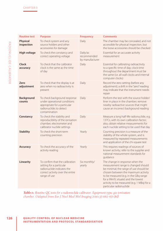
126 QUALIT Y CONTROL OF NUCLEAR MEDICINE INSTRUMENTATION AND PROTOCOL STANDARDISATION
CHAPTER 9
RA
DIO
NU
CLID
E CA
LIBR
ATO
R
Routine test Purpose Frequency Comments
Physical inspection
To check system and any source holders and other accessories for damage
Daily The chamber may be concealed, and not accessible for physical inspection, but the loose accessories should be checked
High voltage To check the constancy and correct operating voltage
Daily/as recommended by manufacturer
Essential for an accurate activity measurement
Clock accuracy
To check that the calibrator clock is the same as the time of day
Daily Essential for calibrating radioactivity to a specific time of day; clock time throughout the department must be the same (i.e. all wall clocks and internal computer clocks)
Zero adjustment
To check that the display is at zero when no radioactivity is present
Daily Record the zero setting (before any adjustment); a drift in the “zero” reading may indicate that the instrument needs repair
Background counts
To check background response under operational conditions appropriate for a particular radionuclide; to detect contamination
Daily Perform the test with the source holder/liner in place in the chamber; remove nearby radioactive sources that might cause an incorrect background reading
Constancy To check the stability and reproducibility of the ionisation chamber, electrometer and calibrator nuclide settings
Daily Measure a long half-life radionuclide, e.g. 137Cs, with its own calibration factor; also, obtain relative measurements for each nuclide setting to be used that day
Stability To check the short-term counting precision
Yearly Counting precision is a measure of the stability of the whole system, and is measured by repeated measurements and application of the chi-square test
Accuracy To check the accuracy of the activity reading
Yearly This requires readings of sources of known activity; refer to the supplier and national measurement standards for guidance
Linearity To confirm that the calibration setting for a particular radionuclide indicates the correct activity over the entire range of use
Six monthly/yearly
The change in response when the measurement range is changed should be minimal; the range of use should be chosen between the maximum activity to be measured (e.g. in the GBq range for a 99mTc eluate) and the lowest activity to be measured (e.g. 1 MBq) for a particular radionuclide
Table 1: Routine QC tests for a radionuclide calibrator. Equipment type: gas ionisation chamber. (Adapted from Eur J Nucl Med Mol Imaging 2010;37:662–671 [6])
127
CHAPTER 9
QUALIT Y CONTROL OF NUCLEAR MEDICINE INSTRUMENTATION AND PROTOCOL STANDARDISATION
RA
DIO
NU
CLID
E CA
LIBR
ATO
R
by radioactive sources that might cause an incorrect background reading must be removed. The test should be performed on each radionuclide setting to be used that day. The magnitude of the background should be established at acceptance test-ing and measured on each day of use prior to first use and checked at each use. The measurement should be taken with no radioactive source in the chamber and on the most common radionuclide setting with the source holder and contamination shield in place. Any increase in the back-ground above the normal value should be investigated. For calibrators that have a background adjust function, background should be within the allowed range of adjustment. Routine performance tests should be corrected for significant back-ground contribution.
Constancy (check source and relative in-strument response) Routinely measuring a long half-life check source (or standard source) allows the user to demonstrate the constancy of the cali-brator’s response (e.g. electrometer stabili-ty or gas pressure changes) over time. The measurements are taken (following the above daily tests) with a long half-life sol-id check source in the source holder in the measurement position. The measurements are compared to the initial measurements performed at acceptance testing and the
results kept for the life of the chamber. The source should be measured on its own setting (e.g. 137Cs on 137Cs). Using the same procedure, the source is also assayed on all commonly used settings (e.g. 137Cs on 99mTc, 137Cs on 131I, 137Cs on 18F, etc.). This is referred to as a “relative response test”[3] and is a measure of the constancy of the calibrator response for commonly used settings. If a standard source is used rather than a test source, the measurement obtained on the setting for the source radionuclide can also serve as an accuracy test. Measurements should be within ±5% of the decay-cor-rected initial values. For secondary stan-dard radionuclide calibrators and reference radionuclide calibrators, measurements should be within ±2%. The measurements should be recorded and available for regu-latory review [2].
Accuracy test Measurements are taken with the refer-ence source in the source holder in the measurement position following the rec-ommended daily tests. In practice, accu-racy testing involves testing with one or more traceable standards. The standards are typically in a solid plastic matrix in a vial format and include 57Co, 133Ba, 137Cs and 60Co. The geometry of these standards is typically not identical to that of the stan-dard sources used by manufacturers to calibrate their systems. The accuracy test

128 QUALIT Y CONTROL OF NUCLEAR MEDICINE INSTRUMENTATION AND PROTOCOL STANDARDISATION
CHAPTER 9
RA
DIO
NU
CLID
E CA
LIBR
ATO
R
is not a calibration; it is a test of system stability. Ideally, the test should use stan-dards of radionuclides that are employed by the radionuclide calibrator manufac-turer to set the system when transporting calibration settings to production models (e.g. 57Co and 137Cs or 57Co and 60Co). As-certaining which radionuclides were used by the manufacturer should be part of the purchase process. The use of one source (e.g. 137Cs) in combination with the routine “relative response tests” should be suffi-cient for most medical facilities. For more complex programmes, instrument stabili-ty should also be checked annually with at least two traceable reference sources and the radionuclides used should vary from year to year[2]. Measurements of the long-lived standards and the two trace-able reference sources should be within ±5% of the decay-corrected initial values. Secondary standard radionuclide calibra-tors and reference radionuclide calibrators should be within ±2%[3]. The measure-ments should be recorded and available for regulatory review.
System linearity A calibrator is considered linear if the ra-tio of the measured response to the pre-dicted response remains constant over the range of current inputs. The decaying source method, the shield method (Fig. 5) and the graded source method may
be used to determine linearity. The grad-ed source method involves manipula-tion and accurate measurement of stock solution aliquots. The decaying source method is recommended for secondary standard radionuclide calibrators and ref-erence radionuclide calibrators. For “field” instruments, the decaying source meth-od should be used at acceptance testing and following repair. The shield method should be sufficient for annual testing; alternatively, the facility can employ the decaying source method. Measurements are taken following the daily tests. The decaying source measurements are tak-en with the source in the source holder in the measurement position. The graded shielding measurements are taken in ac-cordance with the shield manufacturer’s instructions. At acceptance testing and following repair, measurements should be taken using the decaying source method from the highest activity (highest current) measured down to approximately 1 MBq. Annually, measurements should be taken between the maximum activity admin-istered and 1 MBq over the range of use. Measurements should be within ±5% of the expected values. For secondary standard radionuclide calibrators and ref-erence radionuclide calibrators, linearity testing should be performed quarterly us-ing the decaying source method and the measurements should be within ±2%[3].
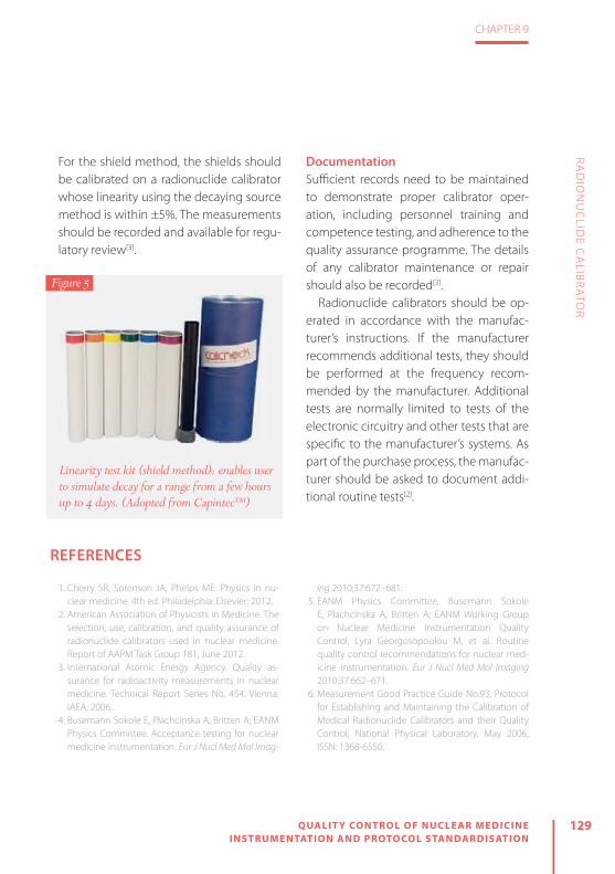
129
CHAPTER 9
QUALIT Y CONTROL OF NUCLEAR MEDICINE INSTRUMENTATION AND PROTOCOL STANDARDISATION
RA
DIO
NU
CLID
E CA
LIBR
ATO
R
For the shield method, the shields should be calibrated on a radionuclide calibrator whose linearity using the decaying source method is within ±5%. The measurements should be recorded and available for regu-latory review[3].
Documentation Suffi cient records need to be maintained to demonstrate proper calibrator oper-ation, including personnel training and competence testing, and adherence to the quality assurance programme. The details of any calibrator maintenance or repair should also be recorded[3].
Radionuclide calibrators should be op-erated in accordance with the manufac-turer’s instructions. If the manufacturer recommends additional tests, they should be performed at the frequency recom-mended by the manufacturer. Additional tests are normally limited to tests of the electronic circuitry and other tests that are specifi c to the manufacturer’s systems. As part of the purchase process, the manufac-turer should be asked to document addi-tional routine tests[2].
Figure 5
Linearity test kit (shield method): enables user to simulate decay for a range from a few hours up to 4 days. (Adopted from CapintecTM)
REFERENCES
1. Cherry SR, Sorenson JA, Phelps ME. Physics in nu-clear medicine. 4th ed. Philadelphia: Elsevier; 2012.
2. American Association of Physicists in Medicine. The selection, use, calibration, and quality assurance of radionuclide calibrators used in nuclear medicine. Report of AAPM Task Group 181, June 2012.
3. International Atomic Energy Agency. Quality as-surance for radioactivity measurements in nuclear medicine. Technical Report Series No. 454. Vienna: IAEA; 2006.
4. Busemann Sokole E, Płachcínska A, Britten A; EANM Physics Committee. Acceptance testing for nuclear medicine instrumentation. Eur J Nucl Med Mol Imag-
ing 2010;37:672–681.5. EANM Physics Committee, Busemann Sokole
E, Płachcínska A, Britten A; EANM Working Group on Nuclear Medicine Instrumentation Quality Control, Lyra Georgosopoulou M, et al. Routine quality control recommendations for nuclear med-icine instrumentation. Eur J Nucl Med Mol Imaging2010;37:662–671.
6. Measurement Good Practice Guide No.93; Protocol for Establishing and Maintaining the Calibration of Medical Radionuclide Calibrators and their Quality Control; National Physical Laboratory, May 2006, ISSN: 1368-6550.

10

10GAMMA PROBES: INTR AOPER ATIVE PROBES AND ORGAN UPTAKE PROBES
by Kristof Baete
QU
ALIT
Y C
ON
TR
OL O
F NU
CLE
AR
ME
DIC
INE
INS
TR
UM
EN
TAT
ION
AN
D P
RO
TOC
OL S
TAN
DA
RD
ISA
TIO
N

132 QUALIT Y CONTROL OF NUCLEAR MEDICINE INSTRUMENTATION AND PROTOCOL STANDARDISATION
CHAPTER 10
GA
MM
A P
RO
BES: IN
TRA
OP
ERA
TIVE
PR
OB
ES AN
D O
RG
AN
UP
TAK
E PR
OB
ES
EQUIPMENT AND BASIC PRINCIPLES
A gamma probe is a radiation detector that allows for the detection and locali-sation of gamma ray-emitting radionu-clides[1, 2]. From this general concept, two device types have been derived for in vivo application in nuclear medicine, without the need for imaging: (a) the intraop-erative probe and (b) the organ uptake probe. The clinical use of these devices is different, but the principles of opera-tion are quite similar and require a largely equivalent quality management (QM).
The intraoperative gamma probe is a compact and hand-held device for conve-nient localisation of radionuclides in the body during surgical interventions[3]. The technique, for which a probe is used, is of-ten referred to as radio-guided surgery. The main application is the sentinel lymph node (SLN) procedure, in which a gamma probe can not only detect and localise an SLN but also reveal occult disease and allows mini-misation of surgical invasiveness[4]. For that purpose, specific probe shapes have been designed, e.g. with a bent tip or laparoscop-ic units. Intraoperative beta probes also ex-ist. However, the specific quality aspects are beyond the scope of this chapter.
The organ uptake probe, on the other hand, uses a more optimised detector
and collimator, which makes it larger and heavier. Therefore, the probe is usually mounted to a fixture or a holder, and al-lows for the measurement of a radionu-clide in vivo using a standardised source–detector setup. The most common appli-cation of this device is the determination of iodine uptake in the thyroid[5]. However, an organ uptake probe can also be used for whole-body dosimetry in molecular ra-diotherapy or as a measuring instrument for isolated limb perfusion.
The gamma probe, in general, needs to be well shielded to protect the detector against unwanted radiation from its sur-roundings. In front of the detector, a prima-ry collimator usually allows the radiation to enter the detector along a certain aperture angle. Manufacturers tend to offer a variety of intraoperative probe units, and addi-tional or exchangeable collimators. Organ uptake probes, on the other hand, are typ-ically manufactured with a dedicated wide or flat field collimator for reliable operation. The detector unit of a gamma probe is usually connected to a console or readout unit. For better agility, some intraoperative probes have detectors that are wirelessly connected to the readout unit. The settings on the console of an intraoperative probe are usually limited, and primarily allow for selection of a radionuclide, count rate in-dicator and sound settings. The acquisition

133
CHAPTER 10
QUALIT Y CONTROL OF NUCLEAR MEDICINE INSTRUMENTATION AND PROTOCOL STANDARDISATION
GA
MM
A P
RO
BES: IN
TRA
OP
ERA
TIVE
PR
OB
ES AN
D O
RG
AN
UP
TAK
E PR
OB
ES
console of an uptake probe is generally much more extensive.
Two types of radiation detector are used for the manufacture of gamma probes: (a) scintillation detectors, or scintillators, and (b) semiconductors.
A scintillator is mostly a crystal that is able to absorb incident gamma rays. The energy of the charged particles, created by the ionisation of the incident gamma rays, is re-emitted as scintillation light. This happens such that the light output of the crystal is proportional to the energy of the incident gamma ray. Subsequently, a light detector converts the scintillation light to a measurable signal that is again proportional to the energy of the incident gamma ray. Scintillator crystals for gam-ma probes are usually inorganic materials, such as NaI(Tl) or CsI(Tl). For higher ener-gy applications, BGO, LSO or GSO may be used owing to their better stopping pow-er. Photomultiplier tubes (PMTs) or photo-diodes are used for the detection of the scintillation photons.
In a semiconductor, the incident radia-tion is measured directly by the amount of electron-hole pairs that are created in proportion to the energy of the gamma ray. The charge carriers are collected using electrodes which then produce a measur-
able electrical signal. Semiconductor de-tectors are usually fabricated out of crys-talline materials, such as CdTe, CdZnTe (or CZT) and HgI2.
Both detector types enable energy dis-crimination of the radiation and allow for the selection of upper and lower energy level discriminators. Events that are re-corded within the energy range can be ac-cepted for further processing, while events outside of that range can be rejected or used for the purpose of scatter correction. In uptake probes, the entire energy spec-trum can be recorded.
The higher density and effective atom-ic number of inorganic scintillators allow for a better detector efficiency at higher energies. However, scintillators in combi-nation with a PMT are sensitive to environ-mental changes and therefore have a less stable energy calibration. Scintillator-based probes with a photodiode have shown an improved ruggedness compared with PMT-based systems. Nevertheless, scintillators have a poorer energy resolution than semi-conductors; this means that a semiconduc-tor has a better scatter rejection capability.
QUALITY ASSURANCEThe international Basic Safety Standards, laid down in European Council Directive
134 QUALIT Y CONTROL OF NUCLEAR MEDICINE INSTRUMENTATION AND PROTOCOL STANDARDISATION
CHAPTER 10
GA
MM
A P
RO
BES: IN
TRA
OP
ERA
TIVE
PR
OB
ES AN
D O
RG
AN
UP
TAK
E PR
OB
ES
2013/59/Euratom, recommend that for all medical radiological equipment a quality assurance (QA) programme needs to be in place in order to uncover defects and to prevent procedural mistakes during the execution of tasks. For the verification of good equipment manufacturing, such a QA programme should include at least: (a) the execution of formal acceptance testing of the instrumentation and (b) the installation of a QC programme. The QA should also involve good registration and documentation of all information related to the use of the system. A good foun-dation for the QM is described in the IEC 61223-1 technical report [6].
The issue of protocol standardisation for the clinical use of gamma probes is a further aspect of QA. The sensitivity of an uptake probe, for example, relies par-ticularly on the source–detector distance and it is important to know the exact data acquisition requirements for acquisition of reliable results. Therefore, standard op-erational procedures should be available to all end-users. Procedural mistakes or pitfalls may include the misuse of colli-mators, isotope or energy settings, and display or audible settings. It is important that all aspects related to the routine use of the device are clarified in written pro-cedures that have been explained well to the end-user.
For intraoperative probes, it is very important to follow the manufacturer’s recommendations regarding instrument cleaning, disinfection and sterile operation. Ignoring the advice can cause serious sys-tem damage. Manufacturers may also pro-vide specific directions for wireless detec-tor probe units, such as recharging of bat-teries and how to safely store probe units.
QA and QC recommendations for gamma probes in general are available in the litera-ture[7–10]. More specific guidelines for intra-operative probes exist[11–13], as do minimum system performance requirements[14, 15].
ACCEPTANCE AND REFERENCE TESTS
Before a gamma probe can be used in clinical practice, its performance should be assessed by a thorough verification of equipment specifications. This assessment is done by a medical physics expert. The acceptance test results are the reference values for the QC tests that will be execut-ed periodically from the moment of com-missioning. Therefore, the acceptance tests should be documented well and ap-pended to the equipment log.
Acceptance tests are usually more com-prehensive than QC tests. A performance

135
CHAPTER 10
QUALIT Y CONTROL OF NUCLEAR MEDICINE INSTRUMENTATION AND PROTOCOL STANDARDISATION
GA
MM
A P
RO
BES: IN
TRA
OP
ERA
TIVE
PR
OB
ES AN
D O
RG
AN
UP
TAK
E PR
OB
ES
analysis encompasses more than those aspects that need to be verified once the equipment is in routine use. Performance tests for gamma probes have been pro-posed in the literature[7, 11, 13]. The most common acceptance and reference tests, in general, are:
» Physical inspection, shielding » Power supply, high voltage, detector gain, battery
» Energy peaking or calibration, energy settings
» Background count rate » Energy resolution » Sensitivity » Counting precision » Linearity of the response
Some device-specific acceptance tests should be added, such as the source ge-ometry influence for uptake probes and spatial resolution for intraoperative probes.
First of all, physical inspection of the probe should be carried out immediately af-ter its reception. Any problem or deficiency observed during the warranty period should be reported and repaired at once. Physical impact to the detector, or its shielding, can lead to malfunctioning or changes in effi-ciency. For intraoperative probes, the signal from a nearby injection site, caused by a leak in the shielding, may conceal an SLN.
The power supply of the device is crit-ical and should be verified. Also, the bat-tery-supplied intraoperative probe unit should be checked. The energy response of an uptake probe depends on the stabil-ity of the high voltage and detector gain, but also on the environmental conditions, such as temperature. Therefore, it is ex-tremely important to assess the detector energy calibration or peaking. After recep-tion, the energy settings should be verified for all used radionuclides, and if necessary the instrument should be (re)calibrated. For an uptake probe, direct spectral analy-sis of the energy peak of a reference source (e.g. caesium-137) is usually obvious. How-ever, visualisation of the energy spectrum of an intraoperative probe by the end-user is not always possible.
The background count rate of a gamma probe is an essential property. Each mea-surement should in fact be preceded or followed by a reading of the background count rate. This system parameter de-pends on the energy settings. For any of these settings, a typical background count rate should be analysed and reference val-ues should be determined. It is important to perform a follow-up of background measurements for various detector loca-tions and positions. In addition to the am-bient conditions, the electronics and con-necting cables can have an impact.

136 QUALIT Y CONTROL OF NUCLEAR MEDICINE INSTRUMENTATION AND PROTOCOL STANDARDISATION
CHAPTER 10
GA
MM
A P
RO
BES: IN
TRA
OP
ERA
TIVE
PR
OB
ES AN
D O
RG
AN
UP
TAK
E PR
OB
ES
The energy resolution of a gamma probe indicates how well it is able to dis-tinguish between closely spaced energy peaks of detected gamma rays in the en-ergy spectrum. A good energy resolution enables the gamma probe to reject scat-tered radiation. Hence, measuring energy resolution can identify the potential for a good system performance. The energy resolution of the probe is quantified by the full-width at half-maximum (FWHM) of the gamma peak at a certain energy. In uptake probes, FWHM can be reported by the console as part of the energy calibra-tion or peaking procedure.
An important parameter is the sensitiv-ity of the gamma probe. In a standardised setup, with a reproducible source-to-de-tector distance and a reference source activity, the count rate response can be determined for the available energy set-tings. The results of these sensitivity mea-surements are the reference values for the subsequent QC tests. These QC measure-ments are therefore usually referred to as a test of the constancy or the long-term stability of the sensitivity. For a more re-alistic analysis, sensitivity may also be as-sessed taking into account the influence of scatter [11].
The short-term stability of the sensitivity is often referred to as the count rate preci-
sion. The decay of a radioactive source is a random process that obeys Poisson statis-tics. A chi-square test can be used to verify that the short-term detector sensitivity is in accordance with the Poisson distribu-tion [1]. With a series of measurements, a chi-square value can be computed and converted to a probability. A high prob-ability (>0.99) means that the variations in the measurements are smaller than statistically expected. This may indicate that, for example, periodic noise is being measured instead of a radioactive source. A low probability (<0.01) indicates that the measurements are too irregular to follow the Poisson nature of the source, and there may be something wrong with the device. A probability of 0.5 indicates a perfect detector behaviour according to Poisson statistics.
The linearity of the detector response, or the count rate capability, verifies the sensitivity at different levels of source ac-tivity. Radiation detectors are influenced by a number of effects at increased count rates. Some of these effects can lead to a shift of the measured energy spectrum. Even though this effect is small for most applications, it should be recognised and measured at least during acceptance test-ing. The most important effect, however, is dead time or the loss of counts. With a decaying source, for example, one can

137
CHAPTER 10
QUALIT Y CONTROL OF NUCLEAR MEDICINE INSTRUMENTATION AND PROTOCOL STANDARDISATION
GA
MM
A P
RO
BES: IN
TRA
OP
ERA
TIVE
PR
OB
ES AN
D O
RG
AN
UP
TAK
E PR
OB
ES
compare the observed detector count rate with the true count rate of the source.
For the uptake probe, a specific accep-tance test should be added. Since the in-strument is used to quantify an amount of activity, it is important to know the influ-ence of different source geometries on the response of the detector. The result of this assessment reveals the robustness of the measurement setup and source (i.e. organ) positioning.
For the intraoperative gamma probe, the directional or angular detector sensi-tivity is very important. A narrow measure-ment field, using an appropriate collima-tor, allows for a high signal to background ratio and SLN detectability. In addition, the lateral detector sensitivity defines the spa-tial resolution of the probe and the ability to separate neighbouring lesions[12].
QUALITY CONTROLThe acceptance and reference tests are complemented by the subsequent QC programme. This part of the overall QM focusses on the fulfilment of the quality re-quirements or acceptability criteria by the performance of verification tests in clinical practice, at regular intervals. If the criteria are not met, corrective actions should be imposed by the medical physics expert,
such that the QC results of the device are brought back in line with the reference values. Moreover, trend analysis of the QC results is a powerful tool for observation of the performance of the instrument over time.
QC recommendations and test fre-quency proposals have been described in a number of publications [8–10]. The most important routine QC tests for gamma probes, in general, are:
» Physical inspection » Power supply, high voltage, gain, battery » Energy peak verification » Background count rate » Sensitivity or constancy » Counting precision
Physical inspection of the gamma probe should be performed at regular inter-vals, preferably before each use. The user should be aware that any observation or knowledge of imprudent use, e.g. a drop or collision of the detector unit, can result in system malfunctioning or changes in the response. Such events should be re-ported immediately and registered in the instrument log, and their impact analysed by a quality inspection of the shielding and detector sensitivity and verification of the energy settings. Also, the power sup-ply should be checked before each use,

138 QUALIT Y CONTROL OF NUCLEAR MEDICINE INSTRUMENTATION AND PROTOCOL STANDARDISATION
CHAPTER 10
GA
MM
A P
RO
BES: IN
TRA
OP
ERA
TIVE
PR
OB
ES AN
D O
RG
AN
UP
TAK
E PR
OB
ES
especially for those mobile units that use batteries.
Regular verification of the energy set-tings of a gamma detector is preferred. For intraoperative probes, the energy spectrum analysis is unfortunately not always available to the end-user. On the other hand, daily verification of the energy peak for quantitative measurements with uptake probes is easy and highly recom-mended. Moreover, a trend analysis of the energy settings has the power to reveal subtle performance changes or drift. The same holds true for the energy resolution. A sudden increase in the energy resolu-tion may be a sign of crystal damage (e.g. a crack) or decoupling of the light detec-tor (PMT, photodiode). A more gradual broadening of the energy resolution may indicate crystal yellowing due to humidity or a deterioration in the light detector.
As mentioned above, the background count rate of a probe is an important
property that should be observed prior to any use. There is the risk of contami-nation of the instrument, or its surround-ings, or the influence of an unexpected local radioactive source. In addition, there may be a sudden change in the detector background reading due to, for example, electronic noise. The observation of an elevated background should always be investigated before proceeding.
The follow-up of detector sensitivity, as determined during acceptance testing, is known as the constancy test. This QC test verifies whether the sensitivity has changed, and it is an easy test to assess influences on the detector response, for example, due to incorrect detector energy settings or the condition of the hardware. As explained above, counting precision analysis may reveal subtle detector issues.
In conclusion, carrying out sustainable QM leads to the correct and safe use of gamma probes in clinical routine.

139
CHAPTER 10
QUALIT Y CONTROL OF NUCLEAR MEDICINE INSTRUMENTATION AND PROTOCOL STANDARDISATION
GA
MM
A P
RO
BES: IN
TRA
OP
ERA
TIVE
PR
OB
ES AN
D O
RG
AN
UP
TAK
E PR
OB
ES
REFERENCES
1. Cherry SR, Sorenson JA, Phelps ME, eds. Physics in nuclear medicine. 4th ed. Philadelphia: Saunders; 2012.
2. Bailey DL, Humm JL, Todd-Pokropek A, van Aswegen A. Nuclear medicine physics. Vienna: International Atomic Energy Agency; 2015. Available from: http://www-pub.iaea.org/books/IAEABooks/10368/Nucle-ar-Medicine-Physics
3. Heller S, Zanzonico P. Nuclear probes and intra-operative gamma cameras. Semin Nucl Med 2011; 41:166–181.
4. Povoski SP, Neff RL, Mojzisik CM, O’Malley DM, Hin-kle GH, Hall NC, et al. A comprehensive overview of radioguided surgery using gamma detection probe technology. World J Surg Oncol 2009;7:11.
5. Hänscheid H, Canzi C, Eschner W, Flux G, Luster M, Strigari L, Lassmann M. EANM Dosimetry Com-mittee Series on Standard Operational Procedures for Pre-Therapeutic Dosimetry – II. Dosimetry prior to radioiodine therapy of benign thyroid diseases. Eur J Nucl Med Mol Imaging 2013;40:1126–1134.
6. International Electrotechnical Commission. Evalua-tion and routine testing in medical imaging depart-ments – Part 1: General aspects. 1993; IEC/TR 61223-1. http://www.iec.ch.
7. Busemann Sokole E, Płachcínska A, Britten A; EANM Physics Committee. Acceptance testing for nuclear medicine instrumentation. Eur J Nucl Med Mol Imag-ing 2010;37:672–681.
8. EANM Physics Committee, Busemann Sokole E, Płachcínska A, Britten A; EANM Working Group on Nuclear Medicine Instrumentation Quality Control, Lyra Georgosopoulou M, et al. Routine
quality control recommendations for nuclear med-icine instrumentation. Eur J Nucl Med Mol Imaging 2010;37:662–671.
9. Quality control of nuclear medicine instruments. IAEA TECDOC 602. Vienna: International Atomic En-ergy Agency; 1991.
10. International Electrotechnical Commission. Nuclear medicine instrumentation – Routine tests – Part 1: Radiation counting systems. 2001. IEC/TR 61948-1. http://www.iec.ch.
11. NEMA NU-3. Performance measurements and qual-ity control guidelines for non-imaging intraopera-tive gamma probes. Rosslyn, VA: National Electrical Manufacturers Association; 2004.
12. Wengenmair W, Kopp J, Sciuk J. Quality criteria of gamma probes: Requirements and future develop-ments. In: Shauer AJ, Becker W, Reiser MF, Possinger K, eds. The sentinel lymph node concept. Berlin Hei-delberg New York: Springer; 2005.
13. Chiesa C, Toscano F, Mariani M, Bomnardieri E. Physical performance parameters of intraoperative probes. In: Mariani G, Giuliano AE, Strauss HW, eds. Radioguided surgery: A comprehensive team ap-proach. New York: Springer; 2008.
14. Matheoud R, Giorgione R, Valzano S, Sacchetti G, Colombo E, Brambilla M. Minimum acceptable sensitivity of intraoperative gamma probes used for sentinel lymph node detection in melanoma patients. Phys Med 2014;30:822–826.
15. European Commission. Radiation Protection 162. Criteria for acceptability of medical radiological equipment used in diagnostic radiology, nuclear medicine and radiotherapy. 2012.

11

11WELL COUNTERS
by Petra Kolenc Peitl and Marko Krošelj
QU
ALIT
Y C
ON
TR
OL O
F NU
CLE
AR
ME
DIC
INE
INS
TR
UM
EN
TAT
ION
AN
D P
RO
TOC
OL S
TAN
DA
RD
ISA
TIO
N

142 QUALIT Y CONTROL OF NUCLEAR MEDICINE INSTRUMENTATION AND PROTOCOL STANDARDISATION
CHAPTER 11
WELL C
OU
NTER
S
PRINCIPLES OF RADIATION DETECTION
Radiation is detected through its inter-action with matter. When ionising radi-ation interacts with matter, ions can be produced directly or indirectly. Alpha or beta particles are highly energised parti-cles that interact directly with atoms and produce charged ion pairs. On the other hand, X-rays and gamma photons interact primarily with orbiting electrons, which are ejected and then interact with other atoms, producing charged ions[1].
There are two basic principles of radia-tion detection:
» Ionisation is caused when the radiation is passing through. The ions produced are detected and measured.
» Electronic excitation in atoms or mol-ecules is caused by the radiation. The excess of energy is then dissipated and detected and measured.
GAMMA AND BETA RADIATION DETECTORS
Three types of detector are used for the quantitative determination of radioactiv-ity: gas-filled ionisation detectors, scintil-lation detectors and semiconductors. No detector is suitable for universal detection of all types of radiation. The factors influ-encing the choice of detector are sensitiv-ity, response to different radiation types,
energy of radiation, detector volume, source geometry and detector dead time.
Gas-filled detectorsGas-filled detectors include ionisation chambers, proportional counters and Gei-ger-Müller (GM) counters. The detector consists of gas contained between two electrodes with a suitable high voltage difference between them. Gas is normally an insulator and no electrical current flows between the electrodes. When ionising radiation passes through the chamber, it causes ionisation of the gas molecules, producing negatively charged electrons and positively charged gas ions. Electrons are attracted to the positively charged electrode (anode) and ionised atoms to the negative electrode (cathode), causing a small amount of electrical current which is proportional to the number of ionising photons or particles in the chamber. To achieve maximum efficiency of gas-filled detectors, the voltage between the elec-trodes must be optimal so as to ensure complete collection of electrons and ions (Fig. 1). If the voltage is too low, recombi-nation of some of the ions and electrons occurs, with no contribution to electrical flow. As the voltage is increased (to 50–300 V), all of the primary charges arising from the initial ionising event are collect-ed (ionisation chamber region). Moreover, increasing the voltage further (to approx.
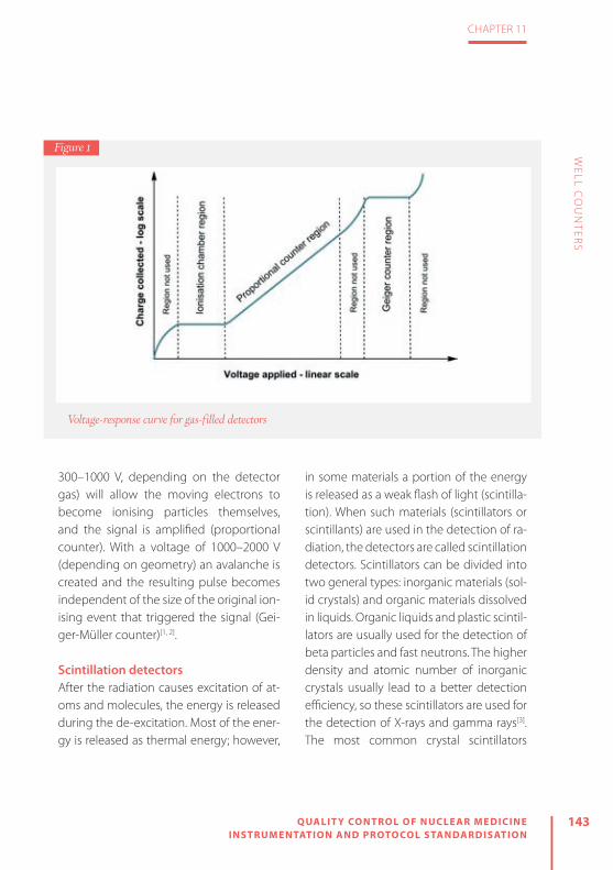
143
CHAPTER 11
QUALIT Y CONTROL OF NUCLEAR MEDICINE INSTRUMENTATION AND PROTOCOL STANDARDISATION
WELL C
OU
NTER
S
300–1000 V, depending on the detector gas) will allow the moving electrons to become ionising particles themselves, and the signal is amplified (proportional counter). With a voltage of 1000–2000 V (depending on geometry) an avalanche is created and the resulting pulse becomes independent of the size of the original ion-ising event that triggered the signal (Gei-ger-Müller counter)[1, 2]. Scintillation detectorsAfter the radiation causes excitation of at-oms and molecules, the energy is released during the de-excitation. Most of the ener-gy is released as thermal energy; however,
in some materials a portion of the energy is released as a weak flash of light (scintilla-tion). When such materials (scintillators or scintillants) are used in the detection of ra-diation, the detectors are called scintillation detectors. Scintillators can be divided into two general types: inorganic materials (sol-id crystals) and organic materials dissolved in liquids. Organic liquids and plastic scintil-lators are usually used for the detection of beta particles and fast neutrons. The higher density and atomic number of inorganic crystals usually lead to a better detection efficiency, so these scintillators are used for the detection of X-rays and gamma rays[3]. The most common crystal scintillators
Voltage-response curve for gas-filled detectors
Figure 1

144 QUALIT Y CONTROL OF NUCLEAR MEDICINE INSTRUMENTATION AND PROTOCOL STANDARDISATION
CHAPTER 11
WELL C
OU
NTER
S
used in nuclear medicine instrumentation are summarised in Table 1. The amount of light produced when gamma rays or beta particles interact with a scintillator is pro-portional to the energy deposited by the radiation in the scintillation material. These scintillations are detected by the light cell or photomultiplier (PM), which converts light energy into weak electric currents that are amplified and converted into volt-age pulses. The heights of these pulses are related to the radiation energy and the number of pulses is related to the activity of the radioisotope[1, 3].
Semiconductor detectorsIn comparison to other materials, semi-conductors have unique characteristics that make them very suitable for ionising
radiation detection: linear response with deposited energy, negligible absorption of energy in the entrance window of the detector, excellent energy resolution, for-mation of pulses with fast rise times and small detector sizes. The signal formation in a semiconductor detector is very similar to that in an ionisation chamber. Ionisa-tion is produced within the sensitive vol-ume of the detector and converted to a voltage pulse that is amplified and count-ed[4]. The most commonly used semicon-ductor materials are elemental silicon (Si) and germanium (Ge). Both Si and Ge have a limited use in the detection of X-rays and gamma rays: (a) they need ancillary cool-ing systems due to a significant amount of thermally induced electrical current at room temperature; (b) they have mod-
Crystal Atomic number, Z
Density (g/cm3)
Hygroscopic Rugged Decay constant (ns)
Emission wavelength (nm)
NaI(Tl) 51 3.67 Yes No 200 410
BaF2 53 4.88 No Yes 0.8 220 and 310
Csl(Tl) 54 4.51 Slightly Yes 1000 565
Gd2SiO5(Ce) (GSO) 59 6.71 NoNo (cleaves easily)
60 430
Lu2SiO5(Ce) (LSO) 65 7.40 No Yes 40 420
Bi4Ge3O12 (BGO) 75 7.13 No Yes 300 480
Table 1: Basic characteristics of common scintillator crystals used in nuclear medicine applications [1, 3]
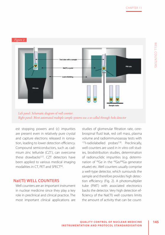
145
CHAPTER 11
QUALIT Y CONTROL OF NUCLEAR MEDICINE INSTRUMENTATION AND PROTOCOL STANDARDISATION
WELL C
OU
NTER
S
est stopping powers and (c) impurities are present even in relatively pure crystal and capture electrons released in ionisa-tion, leading to lower detection efficiency. Compound semiconductors, such as cad-mium zinc telluride (CZT), can overcome these drawbacks[2,5]. CZT detectors have been applied to various medical imaging modalities in CT, PET and SPECT[6].
NaI(Tl) WELL COUNTERSWell counters are an important instrument in nuclear medicine since they play a key role in preclinical and clinical practice. The most important clinical applications are
studies of glomerular filtration rate, cere-brospinal fluid leak, red cell mass, plasma volume and radioimmunoassay tests with 125I-radiolabelled probes[7,8]. Preclinically, well counters are used in in vitro cell stud-ies, biodistribution studies, determination of radionuclidic impurities (e.g. determi-nation of 68Ge in the 68Ge/68Ga generator eluate) etc. Well counters usually comprise a well-type detector, which surrounds the sample and therefore provides high detec-tion efficiency (Fig. 2). A photomultiplier tube (PMT) with associated electronics backs the detector. Very high detection ef-ficiency of the NaI(Tl) well counters limits the amount of activity that can be count-
Left panel: Schematic diagram of well counter. Right panel: Most automated multiple sample systems use a so-called through-hole detector
Figure 2

146 QUALIT Y CONTROL OF NUCLEAR MEDICINE INSTRUMENTATION AND PROTOCOL STANDARDISATION
CHAPTER 11
WELL C
OU
NTER
S
ed (~37 kBq). With higher levels of activity, problems regarding dead time can be en-countered. Dead time is the time required to process individual detected events. The shorter the dead time, the smaller are the dead time losses. NaI(Tl) and semiconduc-tor detector systems usually have a dead time in the range of 0.5–5 μs[2].
The majority of well counters employed in nuclear medicine use thallium-activat-ed sodium iodide [NaI(Tl)] crystals as scin-tillators. NaI(Tl) detectors enable detection of the majority of the gamma-emitting radionuclides in nuclear medicine (e.g. 99mTc, 123I, 111In, 201Tl). Since pure sodium io-dide crystals are scintillators only at liquid nitrogen temperatures, thallium is added in small amounts as a so-called activator centre in the crystal matrix and is respon-sible for the scintillation effect at room temperature. There are many advantag-es of NaI(Tl) which make these detectors suitable for almost all routine applications in nuclear medicine:
» Due to its relatively high density, NaI(Tl) is a good absorber with high detection efficiency for penetrating radiation (X-rays and gamma rays in the energy range from 50 to 250 keV).
» It is a relatively efficient scintillator, since it yields one visible light photon per 30 eV radiation energy absorbed.
» Little loss of scintillation light is caused
by self-absorption, even with large crys-tal sizes.
» It is relatively inexpensive. » The scintillation light is well matched in wavelength to the peak response of the PM photocathode.
However, NaI(Tl) detectors also have some disadvantages: the crystal is quite fragile and easily damaged; NaI is hygro-scopic, which can impair light transmis-sion to the PM upon exposure to moisture; and at energies >250 keV a large volume of NaI(Tl) is required for adequate detec-tion efficiency.
The efficiency of detection depends on the following factors:
» The energy of gamma photons: high-energy photons can pass com-pletely through the crystal matrix with-out energy dissipation.
» Crystal size: larger crystals absorb high-energy photons more efficiently, but the size of the crystal is limited by the optical transmission of scintillation.
» Geometry: it is essential that samples are counted using the same volumes, in the same size tubes and always in the same position within the counter.
» Photomultiplier high voltage: PMTs have to be supplied with an optimal and sta-ble source of high voltage. At too low a voltage, no electrical pulse is produced in PMTs. At increased voltage, sponta-

147
CHAPTER 11
QUALIT Y CONTROL OF NUCLEAR MEDICINE INSTRUMENTATION AND PROTOCOL STANDARDISATION
WELL C
OU
NTER
S
neous electron emission and thermal noise contribute to an increased count rate[1, 9]. The overall advantages of NaI(Tl) make
these detectors the first choice for almost all routine applications in nuclear med-icine involving the detection of gamma rays in the 50–250 keV energy range.
In daily practice, rather than manual well counters, automated multiple sam-ple systems are used (Fig. 3). Most such systems use a so-called through-hole detector, where the sample hole pass-es throughout the NaI(Tl) crystal and the PMT is connected to the side of the scintillator (Fig. 2). Samples in such a de-tector can be automatically positioned at the centre of the NaI(Tl) crystal, inde-
pendently from the sample volume. Sys-tems with an automated sample arm can save a lot of time, since the sample vials can be loaded into a rack and counted automatically. One disadvantage of auto-mated systems is that they are not as well shielded as manual well counters, since there is no lead shielding directly on the top of the sample being counted. This can increase background counting rates, particularly from the other samples in the rack, which can be problematic, especial-ly when low-activity samples are counted together with high-activity samples in the rack.
For very high throughput one can use multidetector systems which can contain multiple NaI(Tl) scintillation detectors. This
Left panel: Example of an automated multisample well type counter. Right panel: Example of computerised routine QC tests
Figure 3

148 QUALIT Y CONTROL OF NUCLEAR MEDICINE INSTRUMENTATION AND PROTOCOL STANDARDISATION
CHAPTER 11
WELL C
OU
NTER
S
allows multiple samples to be counted simultaneously. The individual detectors are separated and shielded from each other to prevent crosstalk, which can give rise to substantial counting error when counting high-energy gamma rays. Back-ground measurements in one detector while counting a sample in an adjacent one can be used to estimate the extent of the crosstalk[2].
Because of the high-energy photons, in the case of PET applications the NaI(Tl) crystal thickness needs to be optimised and the shielding around the detector has to be sufficient to prevent crosstalk from either the samples in adjacent rack positions or the adjacent detector in the case of multidetector systems[10,11]. Re-cently, a high-sensitivity well counter with a bismuth germanate (BGO) detector was developed for preclinical animal PET investigations in which quantitative mea-surements of small blood volumes and activities are needed[12].
QUALITY CONTROLQuality control (QC) is defined as an es-tablished set of ongoing measurements and analyses designed to ensure that the performance of a procedure or instrument is within a predefined acceptable range[13]. Every nuclear medicine instrument, in-cluding well counters, must undergo
strict acceptance testing after installation to verify that the instrument meets spec-ifications and performs according to its clinical purpose. Acceptance testing re-sults are the reference data for future QC tests, and some of them may be repeated periodically (every 6 or 12 months) or after a major service or component change[14]. At the time of installation of a well count-er, physical inspection, energy window calibration and checking of the energy resolution, sensitivity and linearity are per-formed as acceptance testing[15].
Since the electronic components and detectors of well counters can fail or de-teriorate over time, a good quality assur-ance programme should be employed to ensure consistently accurate results. The routine QC tests for well counters in-clude energy window calibration (energy peaking), measurement of background, energy resolution, constancy, efficiency, reproducibility (chi-square test), linearity and minimal detectable activity[13,14]. Table 2 provides an overview of basic QC tests, their purpose and their frequency. Some of the tests are described in detail below:
» When a well counter is equipped with a multi-channel analyser, the energy spectrum should be checked to verify that the photopeak of the radionuclide coincides with the preset photopeak energy window. Usually, energy peaking is done with a 20% photopeak energy

149
CHAPTER 11
QUALIT Y CONTROL OF NUCLEAR MEDICINE INSTRUMENTATION AND PROTOCOL STANDARDISATION
WELL C
OU
NTER
S
window, equivalent to 90–110% of the gamma ray energy of the radionuclide.
» The background counting rate should be checked daily before use for each photo-peak energy window. It is of utmost im-portance to determine the level of back-ground radiation, which can be relatively high and variable in nuclear medicine departments. Measuring a blank sample (empty tube) will also show any contami-nation of the counting well.
» Constancy: at least one reference source traceable to a certified metrology insti-tute should be counted daily. Day-to-day counting rates should be ±10%. Long-lived radionuclides, such as 57Co, 68Ge, 129I and 137Cs, can be used as refer-ence sources for well counter constancy determination.
» Energy resolution evaluates the sharp-ness of a photopeak produced when a well detector is exposed to a single energy radionuclide. It is expressed as the percentage full-width at half-maxi-mum (FWHM) and is checked with a ref-erence source, such as 137Cs. Widening of the peak indicates a malfunction of a certain system component (e.g. break-down of the crystal to photomultiplier tube seal).
» Calibration for each radionuclide should be performed at installation, annually and after any major repair. Efficiency in cpm/Bq can be determined using a pre-cisely calibrated sample, prepared by ap-propriate dilution of a sufficiently large activity of radionuclide to allow accurate measurement in a radionuclide cali-
QC test Frequencya Purpose
Background Daily To detect contamination and to determine background radiation
Constancy Daily Day-to-day counting of long-lived reference sources
Energy window calibration
Daily / quarterly To verify that the photopeak of the radionuclide coincides with the preset photopeak energy window
Energy resolution Quarterly To evaluate the sharpness of a photopeak of reference source radionuclide
Reproducibility Quarterly / half-yearly
To check variations in the set of measurements of reference source (chi-square test)
Efficiency Annually To determine the sensitivity (ε: efficiency) in cpm/Bq for each radionuclide
a The type of test and the frequency depend on the manufacturer’s instructions, national legislation and different guidelines.
Table 2: Summary of routine QC tests performed for well counters

150 QUALIT Y CONTROL OF NUCLEAR MEDICINE INSTRUMENTATION AND PROTOCOL STANDARDISATION
CHAPTER 11
WELL C
OU
NTER
S
brator. On the other hand, a surrogate radionuclide (reference standards, e.g. 57Co instead of 99mTc or 68Ge instead of 18F) can be used to routinely determine the efficiency. In this case, the factor for conversion of the efficiency of the surro-gate to that of a particular radionuclide has to be determined at installation of the well counter.
» Reproducibility of a well counter is checked with the chi-square test, which shows whether random variations in a set of measurements are consistent with the expected Poisson distribution. Any in-consistency with a Poisson distribution is indicative of a well counter malfunction.
» Linearity of activity response is checked either with the decaying source method
or by aliquoting the initial solution with known radioactivity.
» Minimum detectable activity (MDA) is the smallest amount of activity detect-able from background which can be quantified at a given confidence level of 95%.
Whichever tests are performed in the quality assurance programme for a well counter, it is essential that the procedures are documented and the results are re-corded (Fig. 3). Test methods and results have to be maintained in electronic or hard-copy form and archived in order to accurately compare all QC tests with the acceptance test results[14–16].

151
CHAPTER 11
QUALIT Y CONTROL OF NUCLEAR MEDICINE INSTRUMENTATION AND PROTOCOL STANDARDISATION
WELL C
OU
NTER
S
REFERENCES
1. Theobald T. Sampson’s textbook of radiopharmacy. London: Pharmaceutical Press; 2010.
2. Cherry SR, Sorenson JA, Phelps ME. Physics in nuclear medicine. 3rd ed. Philadelphia: Saunders; 2003.
3. Melcher CL. Scintillation crystals for PET. J Nucl Med 2000;41:1051.
4. Seco J, Clasie B, Partridge M. Review on the charac-teristics of radiation detectors for dosimetry and im-aging. Phys Med Biol 2014;59:R303.
5. Owens A, Peacock A. Compound semiconduc-tor radiation detectors. Nuclear Instruments and Methods in Physics Research. Section A: Accelerators, Spectrometers, Detectors and Associated Equipment 2004;531:18–37.
6. Iniewski K. CZT detector technology for medical im-aging. J Instrum 2014;9:C11001.
7. Goldsmith SJ. Radioimmunoassay: Review of basic principles. Semin Nucl Med 1975;5:125–152.
8. Fairbanks VF, Klee GG, Wiseman GA, Hoyer JD, Tefferi A, Petitt RM, et al. Measurement of blood volume and red cell mass: re-examination of 51Cr and 125I meth-ods. Blood Cells Mol Dis 1996;22:169–186.
9. Lubran MM. Quality control of gamma counters. I. Experimental evaluation of sources of error. Ann Clin Lab Sci 1977;7:57–67.
10. Hidex. Automatic gamma counter for nuclear med-icine and PET. 2015 [23.2.2017]. Available from:
http://hidex.com/products/gamma-counters/hi-dex-automatic-gamma-counter/.
11. Lodge MA, Holt DP, Kinahan PE, Wong DF, Wahl RL. Performance assessment of a NaI (Tl) gamma counter for PET applications with methods for im-proved quantitative accuracy and greater standard-ization. EJNMMI Phys 2015;2:11.
12. Yamamoto S, Watabe H, Kanai Y, Watabe T, Imai-zumi M, Shimosegawa E, et al. Development of a high-sensitivity BGO well counter for small animal PET studies. Radiol Phys Technol 2012;5:59–62.
13. Zanzonico P. Routine quality control of clinical nu-clear medicine instrumentation: a brief review. J Nucl Med 2008;49:1114–1131.
14. Busemann Sokole E, Płachcínska A, Britten A, Lyra Georgosopoulou M, Tindale W, Klett R. Routine quality control recommendations for nuclear med-icine instrumentation. Eur J Nucl Med Mol Imaging 2010;37:662–671.
15. Busemann Sokole E, Płachcínska A, Britten A. Ac-ceptance testing for nuclear medicine instrumen-tation. Eur J Nucl Med Mol Imaging 2010;37:672–681.
16. Alessi AM. Quality assurance programs for up-take probes and well counters. 2014 [23.2.2017]. Available from: http://www.biodex.com/nucle-ar-medicine/blog/quality-assurance-programs-up-take-probes-and-well-counters.

12

12R ADIATION PROTEC TION MEASUREMENT EQUIPMENT
by Søren Holm
QU
ALIT
Y C
ON
TR
OL O
F NU
CLE
AR
ME
DIC
INE
INS
TR
UM
EN
TAT
ION
AN
D P
RO
TOC
OL S
TAN
DA
RD
ISA
TIO
N
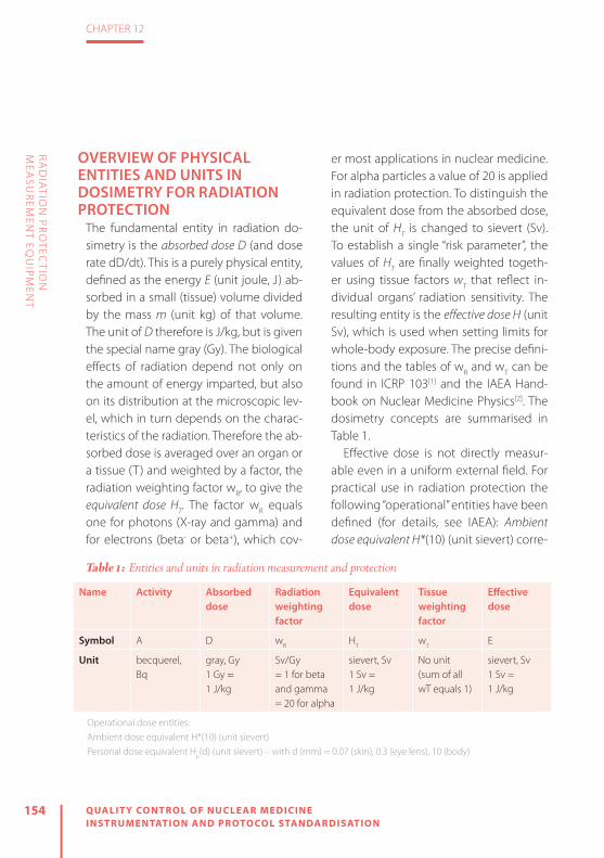
154 QUALIT Y CONTROL OF NUCLEAR MEDICINE INSTRUMENTATION AND PROTOCOL STANDARDISATION
CHAPTER 12
RA
DIA
TION
PR
OTEC
TION
M
EASU
REM
ENT EQ
UIPM
ENT
OVERVIEW OF PHYSICAL ENTITIES AND UNITS IN DOSIMETRY FOR RADIATION PROTECTION
The fundamental entity in radiation do-simetry is the absorbed dose D (and dose rate dD/dt). This is a purely physical entity, defined as the energy E (unit joule, J) ab-sorbed in a small (tissue) volume divided by the mass m (unit kg) of that volume. The unit of D therefore is J/kg, but is given the special name gray (Gy). The biological effects of radiation depend not only on the amount of energy imparted, but also on its distribution at the microscopic lev-el, which in turn depends on the charac-teristics of the radiation. Therefore the ab-sorbed dose is averaged over an organ or a tissue (T) and weighted by a factor, the radiation weighting factor wR, to give the equivalent dose HT. The factor wR equals one for photons (X-ray and gamma) and for electrons (beta- or beta+), which cov-
er most applications in nuclear medicine. For alpha particles a value of 20 is applied in radiation protection. To distinguish the equivalent dose from the absorbed dose, the unit of HT is changed to sievert (Sv). To establish a single “risk parameter”, the values of HT are finally weighted togeth-er using tissue factors wT that reflect in-dividual organs’ radiation sensitivity. The resulting entity is the effective dose H (unit Sv), which is used when setting limits for whole-body exposure. The precise defini-tions and the tables of wR and wT can be found in ICRP 103[1] and the IAEA Hand-book on Nuclear Medicine Physics[2]. The dosimetry concepts are summarised in Table 1.
Effective dose is not directly measur-able even in a uniform external field. For practical use in radiation protection the following “operational” entities have been defined (for details, see IAEA): Ambient dose equivalent H*(10) (unit sievert) corre-
Name Activity Absorbed dose
Radiation weighting factor
Equivalent dose
Tissue weighting factor
Effectivedose
Symbol A D wR HT wT E
Unit becquerel, Bq
gray, Gy1 Gy =1 J/kg
Sv/Gy = 1 for beta and gamma= 20 for alpha
sievert, Sv1 Sv =1 J/kg
No unit (sum of all wT equals 1)
sievert, Sv 1 Sv =1 J/kg
Operational dose entities:Ambient dose equivalent H*(10) (unit sievert)Personal dose equivalent Hp(d) (unit sievert) – with d (mm) = 0.07 (skin), 0.3 (eye lens), 10 (body)
Table 1: Entities and units in radiation measurement and protection
155
CHAPTER 12
QUALIT Y CONTROL OF NUCLEAR MEDICINE INSTRUMENTATION AND PROTOCOL STANDARDISATION
RA
DIA
TION
PR
OTEC
TION
M
EASU
REM
ENT EQ
UIPM
ENT
sponding to equivalent dose at a depth of 10 mm in tissue (equivalent) material, and personal dose equivalent Hp(d) (unit sievert) defined as the equivalent dose at a depth d in soft tissue below a specified point in the body. Relevant values of d are d=10 mm (used for estimating effective dose), d=0.07 mm (used for skin dose) and d=0.3 mm (for dose to the eye lens). These entities are listed here because radiation protection equipment will nor-mally be specified (calibrated) in terms of H* or Hp(d).
RULES AND REGULATIONS IN RADIATION PROTECTION
The fundamental concepts are laid out by ICRP in their recommendations, the most recent general one being from 2007 (ICRP 103[1]). Based on this, international (IAEA) and regional (EU) Basic Safety Standards (BSS) have been issued[3,4]. The EU BSS-di-rective (Euratom 2013/59[4]) must be im-plemented in the national legislations of all the EU member states by February 2018. Despite the European cooperation between authorities and attempts to har-monise, there will be some differences between countries. Further, local institu-tions may have their own (stronger) de-mands, and therefore it is recommended always to look (also) at what local rules may apply.
Two important issues of interest that were already present in previous directives, but may be interpreted differently in the new implementation, are: categorisation of (exposed) workers and classification of workplaces. Workplaces must be divided into controlled areas with more restricted access and surveillance and supervised areas with a lower risk and therefore more ready access. Workers are divided into two groups: group A, who are “liable to receive an effective dose greater than 6 mSv per year or an equivalent dose greater than 15 mSv per year for the lens of the eye or greater than 150 mSv per year for skin and extremities”, and group B, who are not. It is possible to design nuclear medicine de-partments and to plan the work so that it is highly unlikely that anyone (technolo-gists, physicians or medical physicists) will exceed the dose limits listed above. How-ever, even then it will still be necessary to monitor (most of ) the staff to document this. The rest of this chapter shows the types of equipment that can be used for monitoring of persons and workplaces.
DOSIMETERS FOR PERSONAL MONITORING
Monitoring of effective dose and finger dose has been routine for decades. The recently lowered dose limit to the eye lens[5] has created some uncertainty as to
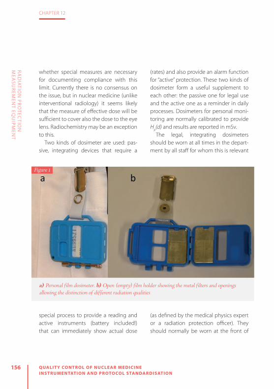
156 QUALIT Y CONTROL OF NUCLEAR MEDICINE INSTRUMENTATION AND PROTOCOL STANDARDISATION
CHAPTER 12
RA
DIA
TION
PR
OTEC
TION
M
EASU
REM
ENT EQ
UIPM
ENT
whether special measures are necessary for documenting compliance with this limit. Currently there is no consensus on the issue, but in nuclear medicine (unlike interventional radiology) it seems likely that the measure of effective dose will be sufficient to cover also the dose to the eye lens. Radiochemistry may be an exception to this.
Two kinds of dosimeter are used: pas-sive, integrating devices that require a
special process to provide a reading and active instruments (battery included!) that can immediately show actual dose
(rates) and also provide an alarm function for “active” protection. These two kinds of dosimeter form a useful supplement to each other: the passive one for legal use and the active one as a reminder in daily processes. Dosimeters for personal moni-toring are normally calibrated to provide Hp(d) and results are reported in mSv.
The legal, integrating dosimeters should be worn at all times in the depart-ment by all staff for whom this is relevant
(as defined by the medical physics expert or a radiation protection officer). They should normally be worn at the front of
Figure 1
a) Personal film dosimeter. b) Open (empty) film holder showing the metal filters and openings allowing the distinction of different radiation qualities

157
CHAPTER 12
QUALIT Y CONTROL OF NUCLEAR MEDICINE INSTRUMENTATION AND PROTOCOL STANDARDISATION
RA
DIA
TION
PR
OTEC
TION
M
EASU
REM
ENT EQ
UIPM
ENT
the body and at belt height. When work-ing in front of a shielded workplace, the dosimeter may be placed at chest level in order to avoid underestimation of the ex-posure here. Pregnant staff members (to the extent that they are allowed to work at all in the department) should always wear the dosimeter at or near belt level to give a better representation of the dose to the foetus.
Electronic dosimeters can be considered optional. They are most important for new staff or when introducing new procedures. They may also be given to short-term visi-tors for whom the monthly (or 3-monthly) dosimeters do not make sense.
The classical personal dose meter is film based (Fig. 1a); the interaction of ionising radiation with a photographic film was what in 1896 led Becquerel to the detec-tion of radioactivity. As with other film ma-terials, processing (developing, fixing) is re-quired to show the exposure, and a special device is needed to read and convert the gray scale into a dose value. The placement of the film in a specially designed film holder (Fig. 1b) with different thickness-es of plastic material and metal filters (Al, Sn, In, Cd, Pb) to some extent allows de-termination of the radiation quality (soft/hard gamma, soft/hard beta, neutron). Further, contamination by small drops of radioactivity can easily be identified. Film has the advantage that the developed ma-
terial can be stored and will retain the in-formation for potential later re-evaluation. Against the film material speaks the rather high uncertainty at low exposure, which over the years has become more import-ant as the dose limits have been reduced and the price of the silver in the emulsion has increased.
An alternative that is becoming increas-ingly common is the use of thermolumi-nescence dosimetry (TLD). Many materials have the property, when irradiated, that some of the absorbed energy will get “trapped”. Electrons are excited out of their stable ground state and end up in a high-er energy state that is also quite stable at normal (room) temperatures. By heating (thermo = T) the material to 180–260°C, the electrons are “lifted” out of the traps and will fall back emitting light (lumines-cence = L). The amount of light can be collected and will be proportional to the energy absorbed in the first place (dose = D). For dosimetry, the most common basis material is lithium-fluoride (LiF) with certain impurities added to determine its properties in detail. The material is “tissue equivalent” and can be formed into tab-lets (Fig. 2); in addition to being used for whole-body monitoring (Fig. 3), these tab-lets are small enough that they not only can be mounted in finger rings or wrist do-simeters (Fig. 4) but can even be attached to the fingertips (and covered by gloves).

158 QUALIT Y CONTROL OF NUCLEAR MEDICINE INSTRUMENTATION AND PROTOCOL STANDARDISATION
CHAPTER 12
RA
DIA
TION
PR
OTEC
TION
M
EASU
REM
ENT EQ
UIPM
ENT
As soon as the reading (heating) has been performed, the information vanishes by “annealing” and the tablet can be reused. The minimum detection limit for TLD is lower than for film, but TLD provides little information on radiation quality, contam-ination is more difficult to observe and re-examination after the first reading is not possible.
Electronic dosimeters (Fig. 5) are usual-ly based on silicon solid-state detectors,
where ionising radiation produces pairs of electrons/holes that can be collected and converted to a dose reading in µSv/h. The advantage of such an instrument is straightforward. The user can keep an eye on the dose rate during different work pro-cesses and can even be warned against
(unexpected) higher dose levels. The set-ting of the alarm level requires some con-sideration when working with patients who may be unnecessarily scared if they observe that they are triggering the signal.
Film and TLD require no quality control from the user except for a simple check that the film holder or TLD package is not damaged. Most often the handling of film or the TLD is performed by cen-tralised institutions that must be accred-
ited to perform that task and adhere to certain standards, e.g. ISO/IEC 17025, ISO 14146. Electronic dosimeters will typically loudly signify that they are running low on battery; if they do not do so, then it is the responsibility of the user to check and detect this. The function of alarm
Figure 2
The size of a TLD tablet is only a few millimetres
Figure 3
The author’s current TLD

159
CHAPTER 12
QUALIT Y CONTROL OF NUCLEAR MEDICINE INSTRUMENTATION AND PROTOCOL STANDARDISATION
RA
DIA
TION
PR
OTEC
TION
M
EASU
REM
ENT EQ
UIPM
ENT
levels can be checked (again, by the user) simply by moving the device gradually towards any (sufficiently strong) gamma source, e.g. a 57Co flood source, a 137Cs or 68Ge calibration source or a vial contain-ing99mTc or 18F (in this last case, the device must be brought just above the vial as it is shielded at the sides!). The absolute calibration should be certified at delivery, and constancy of the reading can then be checked using, for example, a long-lived
calibration source in a fixed geometry. Proving the correct absolute calibration from first principles is not easy even with a known, certified calibration source. Re-member (if trying this) that the distance square law is valid only for the direct radi-ation and therefore the presence of scat-
tering material in such a measurement should be minimised.
Most personal electronic dosimeters have an energy response (efficiency) that rapidly falls off towards zero for photon energies below 30–50 keV, dependent on the type. This may result in underestima-tion of doses, in particular if a major part of the radiation consists of scattered radiation at low energy. However, a comparison in a PET department has shown that results ob-
tained using dosimeter film, a TLD and an electronic dosimeter are reasonably consis-tent[6]. In such a comparison, one key issue is the handling of (natural) background radiation, which is corrected for in the in-tegrating film or TLD systems by subtrac-tion of the measured value from an “unex-
Figure 4
TLD tablets can be used for finger and wrist dosimetry and even attached to the fingertips
Figure 5
Two examples of personal electronic dosimeters
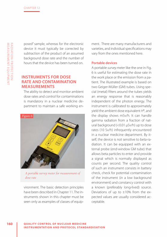
160 QUALIT Y CONTROL OF NUCLEAR MEDICINE INSTRUMENTATION AND PROTOCOL STANDARDISATION
CHAPTER 12
RA
DIA
TION
PR
OTEC
TION
M
EASU
REM
ENT EQ
UIPM
ENT
posed” sample, whereas for the electronic device it must typically be corrected by subtraction of the product of an assumed background dose rate and the number of hours that the device has been turned on.
INSTRUMENTS FOR DOSE RATE AND CONTAMINATION MEASUREMENTS
The ability to detect and monitor ambient dose rates and control for contaminations is mandatory in a nuclear medicine de-partment to maintain a safe working en-
vironment. The basic detection principles have been described in Chapter 11. The in-struments shown in this chapter must be seen only as examples of classes of equip-
ment. There are many manufacturers and varieties, and individual specifications may vary from the ones mentioned here.
Portable devicesA portable survey meter like the one in Fig. 6 is useful for estimating the dose rate in the work place or the emission from a pa-tient. The illustrated example is based on two Geiger-Müller (GM) tubes. Using spe-cial (metal) filters around the tubes yields an energy response that is reasonably independent of the photon energy. The instrument is calibrated to approximately yield the ambient dose equivalent H*, and the display shows mSv/h. It can handle gamma radiation from a fraction of nat-ural background (<0.01 µSv/h) up to dose rates (10 Sv/h) infrequently encountered in a nuclear medicine department. By it-self, the device is not sensitive to beta-ra-diation. It can be equipped with an ex-ternal probe (end-window GM tube) that allows beta particles to enter and provide a signal which is normally displayed as counts per second. The quality control of such an instrument consists in battery check, check for potential contamination of the instrument (in a low background environment) and constancy control with a known (preferably long-lived) source. Deviations of up to ±10% from the ex-pected values are usually considered ac-ceptable.
Figure 6
A portable survey meter for measurement of dose rate

161
CHAPTER 12
QUALIT Y CONTROL OF NUCLEAR MEDICINE INSTRUMENTATION AND PROTOCOL STANDARDISATION
RA
DIA
TION
PR
OTEC
TION
M
EASU
REM
ENT EQ
UIPM
ENT
Contamination monitors exist in many forms, but typically they are either large-ar-ea (100–200 cm2), rectangular detectors (Fig. 7a,b) or circular (cylindrical) detectors that detect at an “end-window” of diame-ter 2–6 cm (Fig. 7c). Obviously the large-ar-ea detectors in general have a higher ef-
fi ciency which is useful when surveying a large surface. The smaller ones, on the oth-er hand, are easier to apply in the search for localized spills (single drops), where the large-area monitors yield a rather constant signal when moving over the spot.
Some instruments look quite similar, and yet their probes have very diff erent properties. It is easily understandable that a detector can function only if the radi-ation of concern has a high probability of entering the active detector volume and a high probability of being stopped (interacting) in that volume. Therefore a
detector for particles (alpha, beta) must have a thin entry window to facilitate their access, and a detector for photons (X-ray, gamma) must have a high densi-ty and high atomic number to provide stopping power. Figure 8 shows a gam-ma source (137Cs) in the upper half and
a beta source (36Cl) in the lower half. The instrument to the right has an end-win-dow GM tube which is sensitive to beta particles and will even detect some alpha particles. It has a rather low sensitivity for gamma photons because it is a gas detector. To the left is a scintillation (NaI) detector which is highly sensitive to gam-ma rays (and X-rays). The alumina cover of the crystal, however, does not allow beta particles (at least below 1 MeV) to enter. It can therefore be very important to choose the right instrument in a given situation. Some instruments (like the one
a) Contamination monitor with a large detection area. b) For particle measurements, the bottom plate must be slid off. Note the mesh protecting the thin cover foil. c) Small circular contamination monitor
Figure 7
(a) (b) (c)

162 QUALIT Y CONTROL OF NUCLEAR MEDICINE INSTRUMENTATION AND PROTOCOL STANDARDISATION
CHAPTER 12
RA
DIA
TION
PR
OTEC
TION
M
EASU
REM
ENT EQ
UIPM
ENT
in Fig. 7a) use a plastic scintillator covered with a thin foil (lightproof ) and allow for detection of both particles and photons with reasonable effi ciency.
Quality control of contamination monitors should include battery check, background check and check for con-
stancy with a relevant source, preferably long lived, in a fi xed geometry. For the end-window detectors (and cylindrical NaI detectors) a point source will be a nat-ural choice. For large-area monitors, a foil of, for example, 100 cm2 with a weak gam-ma or beta activity is convenient (Fig. 9).
Figure 8
A demonstration of the difference in detection properties between a scintillation counter (left) and a GM tube (right). In (a), with the detectors pointing to a gamma source, the scintillation counter yields 100 cps while the GM tube only shows 5–6. With the beta source, the scintillation counter (b) is down to 5 cps (mostly background) while the GM tube in (c) shows almost 50 cps
(a)
(b) (c)

163
CHAPTER 12
QUALIT Y CONTROL OF NUCLEAR MEDICINE INSTRUMENTATION AND PROTOCOL STANDARDISATION
RA
DIA
TION
PR
OTEC
TION
M
EASU
REM
ENT EQ
UIPM
ENT
Not all contamination monitors can detect alpha particles. A particularly thin window is required for the particles to en-ter. When measuring alpha radiation on a surface, it is also important to remember that the range even in air is quite limited and that the energy is gradually lost along the path. For protection, it is a reasonably easy rule of thumb that the range in air is always below 10 cm. For a 5-MeV alpha particle, however, the range is really only 4.5 cm, and after passing the air gap from the source to the detector, the particle
should still have enough energy to pene-trate the cover foil and trigger the detec-tor, which may use energy discrimination to distinguish alpha from beta particles (and noise). A ~3-μm cover foil may cor-respond to 0.5 cm of air, so to be sure of detection the distance should not exceed 2 cm (Fig. 10). Then it is obvious that there is a high probability of contaminating the foil by touching potential activity directly. It is possible to cover the instrument by a single layer of standard household plastic foil (8–10 µm) and still have a signal. In this way a potential contamination can easily be removed by replacing the plastic foil. Alpha monitors should be checked for constancy with an appropriate source, which could be a point source of 241Am, which has a half-life of 433 years.
Stationary instrumentsA hand-foot monitor (Fig. 11) is a conve-nient piece of equipment for a fast check of personnel contamination. One of the hand detectors can be removed from its position to scan clothes. In older instru-ments, the panels used to be proportion-al counters (gas-based) but today plastic scintillator systems are common. Quality control of this kind of monitor is the same as for portable contamination monitors, i.e. checking at regular intervals for back-ground and constancy, e.g. with a long-lived beta-active sheet (14C or 90Sr).
Figure 9
Example of calibration/test sources for large-area detectors
∫

164 QUALIT Y CONTROL OF NUCLEAR MEDICINE INSTRUMENTATION AND PROTOCOL STANDARDISATION
CHAPTER 12
RA
DIA
TION
PR
OTEC
TION
M
EASU
REM
ENT EQ
UIPM
ENT
At certain places in the department it may be relevant to install a survey instru-ment that can warn against (temporary) high dose rates. This could be outside a cyclotron room, next to a radiochemistry lab or in other places where a (temporary) warning is appropriate. Readings can be checked with a 137Cs source in a reproduc-ible position (assuming low or corrected background).
Acknowledgeme nts. The author wish-es to thank technologists Marianne Fed-erspiel, Elin Lindell, Eunice Saxtoft and Susanne Svalling for valuable input to and discussion and criticism of the contents of this chapter.
Figure 10
When measuring for alpha-particles, a close distance to the (potential) source is mandatory
Figure 11
A hand-foot monitor is useful for a fast check of personal contamination

165
CHAPTER 12
QUALIT Y CONTROL OF NUCLEAR MEDICINE INSTRUMENTATION AND PROTOCOL STANDARDISATION
RA
DIA
TION
PR
OTEC
TION
M
EASU
REM
ENT EQ
UIPM
ENT
REFERENCES
1. ICRP. The 2007 Recommendations of the Interna-tional Commission on Radiological Protection. ICRP publication 103. Ann ICRP 2007;37(2–4):1–332.
2. International Atomic Energy Agency. Nuclear medicine physics. Vienna: IAEA, Vienna; 2015. Web: http://www-pub.iaea.org/books/IAEABooks/10368/Nuclear-Medicine-Physics-A-Handbook-for-Teach-ers-and-Students. Accessed 1 March, 2017.
3. International Basic Safety Standards for Protection Against Ionizing Radiation and for the Safety of Radiation Sources. IAEA Safety Series No. 115. ISBN: 92-0-104295-7.
4. European Council Directive 2013/59/Euratom on ba-sic safety standards for protection against the dan-
gers arising from exposure to ionising radiation and repealing Directives 89/618/Euratom, 90/641/Eura-tom, 96/29/Euratom, 97/43/Euratom and 2003/122/Euratom. OJ of the EU. L13; 57: 1–73 (2014).
5. ICRP statement on tissue reactions and early and late effects of radiation in normal tissues and organs – threshold doses for tissue reactions in a radiation protection context. ICRP publication 118. Ann ICRP 2012;41(1–2):1–322.
6. Dall B, Svalling S, Holm S. A comparison of three dif-ferent methods for measuring whole body radiation exposure. Eur J Nucl Med Mol Imaging 2008;35 (Suppl 2):S214.

166 QUALIT Y CONTROL OF NUCLEAR MEDICINE INSTRUMENTATION AND PROTOCOL STANDARDISATION
ISBN: 978-3-902785-13-8
Publisher:European Association of Nuclear MedicineSchmalzhofgasse 26, 1060 Vienna, AustriaPhone: +43-(0)1-890 27 44 | Fax: +43-(0)1-890 44 27-9Email: [email protected] | URL: www.eanm.org
Main-Editor:Sebastijan Rep
Co-Editors:Marie Claire AttardLuca CamoniAndrea Santos
English Language Editing:Rick Mills
Project Management:Magdalena Schwartz
Content:No responsibility is taken for the correctness of this information.Information as per date of printing September 2017.
Layout & DesignRobert Punz European Association of Nuclear MedicineSchmalzhofgasse 26, 1060 Vienna, AustriaPhone: +43-(0)1-890 27 44 | Fax: +43-(0)1-890 44 27-9Email: [email protected] | URL: www.eanm.org
Printing“agensketterl” Druckerei GmbH Druckhausstraße 1, A-2540 Bad Vöslau, Austria Email: [email protected] | URL: www.agensketterl.at
IMPRINT


http://www.eanm.org/publications/technologists-guide/
FIND MORE EANM TECHNOLOGISTS GUIDES HERE