quality control procedures applied to nuclear instruments · pdf file ·...
TRANSCRIPT

IAEA-TECDOC-1599
Quality Control ProceduresApplied to Nuclear Instruments
Proceedings of a Technical MeetingVienna, 23–24 August 2007
September 2008

IAEA-TECDOC-1599
Quality Control Procedures Applied to Nuclear Instruments
Proceedings of a Technical Meeting Vienna, 23–24 August 2007
November 2008

The originating Section of this publication in the IAEA was:
Physics Section International Atomic Energy Agency
Wagramer Strasse 5 P.O. Box 100
A-1400 Vienna, Austria
QUALITY CONTROL PROCEDURES APPLIED TO NUCLEAR INSTRUMENTS IAEA, VIENNA, 2008 IAEA-TECDOC-1599
ISBN 978–92–0–108308–1 ISSN 1011–4289
© IAEA, 2008
Printed by the IAEA in Austria November 2008

FOREWORD
Quality Control (QC), test procedures for Nuclear Instrumentation are important for assurance of proper and safe operation of the instruments, especially with regard to equipment related to radiological safety, human health and national safety. Correct measurements of radiation parameters must be ensured, i.e., accurate measurement of the number of radioactive events, counting times and in some cases accurate measurements of the radiation energy and occuring time of the nuclear events. There are several kinds of testing on nuclear instruments, for example, type-testing done by suppliers, acceptance testing made by the end users, Quality Control tests after repair and Quality Assurance/Quality Controls tests made by end-users. All of these tests are based in many cases on practical guidelines or on the experience of the own specialist, the available standards on this topic also need to be adapted to specific instruments.
The IAEA has provided nuclear instruments and supported the operational maintenance efforts of the Member States. Although Nuclear Instrumentation is continuously upgraded, some older or aged instruments are still in use and in good working condition. Some of these instruments may not, however, meet modern requirements for the end-user therefore, Member States, mostly those with emerging economies, modernize/refurbish such instruments to meet the end-user demands. As a result, new instrumentation which is not commercially available, or modernized/refurbished instruments, need to be tested or verified with QC procedures to meet national or international certification requirements.
A technical meeting on QC procedures applied to nuclear instruments was organized in Vienna from 23 to 24 August 2007. Existing and required QC test procedures necessary for the verification of operation and measurement of the main characteristics of nuclear instruments was the focus of discussion at this meeting. Presentations made at the technical meeting provided valuable information, new proposals, and technical opinions which have been compiled and summarized in this publication and should be useful for technical staff dealing with QC test procedures for maintenance, repair, design and modernization/refurbishment of nuclear instruments. Nine experts in this field as well as users of nuclear instruments presented their latest results; discussions held during the meeting and following the presentations included many technical comments. This publication is a culmination of the interactions and presentations which occurred during the meeting. The IAEA thanks all the participants for their active involvement in the meeting. Special thanks are given to F. J. Ramirez for serving as rapporteur during the meeting, and for his assistance in the report’s preparation.
The IAEA officers responsible for this publication were H. Kaufmann and F. Mulhauser of the Division of Physical and Chemical Sciences.

EDITORIAL NOTE
This publication has been prepared from the original material as submitted by the authors. The views expressed do not necessarily reflect those of the IAEA, the governments of the nominating Member States or the nominating organizations.
The use of particular designations of countries or territories does not imply any judgement by the publisher, the IAEA, as to the legal status of such countries or territories, of their authorities and institutions or of the delimitation of their boundaries.
The mention of names of specific companies or products (whether or not indicated as registered) does not imply any intention to infringe proprietary rights, nor should it be construed as an endorsement or recommendation on the part of the IAEA.
The authors are responsible for having obtained the necessary permission for the IAEA to reproduce, translate or use material from sources already protected by copyrights.

CONTENTS
1. SUMMARY...................................................................................................................... 1
1.1. Introduction................................................................................................................ 1 1.2. International standards for nuclear instrumentation .................................................. 2 1.3. Special test procedures for newly developed instruments ......................................... 3 1.4. QC test procedures for manufacturing of detectors ................................................... 3 1.5. QC test procedures for troubleshooting of tld readers ............................................... 4 1.6. QC test procedures for radiation detectors and associated counting systems............ 4
1.6.1. QC test procedures for radiation detectors..................................................... 5 1.6.2. QC test procedures for radiation survey monitors ......................................... 5 1.6.3. QC test procedures for nuclear counting systems.......................................... 6
1.7. Future/further needs of the Member States................................................................ 6 1.8. Conclusions................................................................................................................ 6
PRESENTATIONS
International standards and quality control procedures applied to nuclear instruments .......... 11 P. Urbański
Quality assurance plan for gas filled detector manufacturing.................................................. 17 C. G. Hofer, M. E. Miller, S.I. Thorp, I. Martínez
A fault tree for common problems with TLD readers.............................................................. 21 M. López Rodríguez
QC test on radiation detectors and the associated nuclear counting systems........................... 27 F.J. Ramírez-Jiménez, L. Mondragón-Contreras, P. Cruz-Estrada
Quality control tests for radiation survey instruments ............................................................. 35 S.L.C. Mdoe, Y.Y Sungit
Quality control test for nuclear counting systems.................................................................... 43 R. Engels and H. Kaufmann
Quality control of nuclear ADC’s with a new FPGA based pulser ......................................... 53 P.P. Vaidya, M. Vinod, T.S. Ananthakrishnan, P.K. Mukhopadhyay
ABBREVIATIONS AND ACRONYMS ................................................................................ 57
LIST OF PARTICIPANTS ...................................................................................................... 59

1. SUMMARY
1.1. INTRODUCTION
Nuclear instruments (NI) are the fundamental tools for deriving benefits from any application of nuclear science and technology. They are widely used in areas such as environmental monitoring, industry, human health, and nuclear research; therefore, the user profile can vary from academic researchers, healthcare professionals, industrial technologists, and environmental scientists to radiation protection and reactor personnel. The International Atomic Energy Agency (IAEA) assists the Member States in the acquisition, maintenance, repair, modification and refurbishment of nuclear instruments. In this respect, Member States have an interest in building up their capacity for self-reliance and sustainable activities. Practical expertise and transfer of knowledge are pre-requisites for progress towards these objectives. There are several kinds of testing on nuclear instruments, for example, type-testing done by suppliers to ensure that equipment meets design criteria and functionality, it is similar to the acceptance testing that must be made at the reception of the equipment by the end users. In many Member State laboratories, Quality Control (QC) tests after repair are needed to guarantee that the instrument keeps its original characteristics. Quality Assurance (QA)/QC tests are done by end-users, for example, medical physicists in the field of human health to ensure clinical fitness of instrumentation. In many cases, electronic engineers need to make these measurements in order to guarantee the accuracy and precision of the obtained results. QC procedures are a key aspect in the operation of instruments and in the reliability of the data obtained. These procedures are particularly important as several national institutes have modernized/refurbished their nuclear instruments to meet current end-user demands like automatic control, data acquisition, and evaluation towards the traceability of data. Modernizations such as these highlight a growing demand for proper and suitable QC procedures for testing as well as relevant test instructions. In these proceedings some examples of the different kinds of testing are addressed as samples of the real work made in the field in order to figure out the complexity of the activities of the Nuclear Instrumentation specialists.
Improper operation of nuclear instruments can lead to inaccuracy of a whole nuclear system, a condition which can be identified through proper test procedures. There are test procedures both for specific sections of radiation measuring systems and also for complete systems in order to verify that items meet their specified requirements or technical specifications. Test procedures are therefore important for quality control as they enhance the reliability of the operation of instruments and of the data obtained.
The refurbishment of nuclear instruments deals with typical nuclear sections like the single-channel analyser (SCA), the multi-channel analyser (MCA) and counting systems. These basic sections are encountered in any equipment for environmental radiation monitoring, nuclear applications in human health, nuclear research and nuclear technology based industrial applications. The refurbishment/modernization of equipment improves the quality of the measurements and, in many cases, allows the continuation of vital activities that would otherwise be stopped due to the unavailability of proper high cost instruments. Refurbishment or modernization is commonly performed by using microprocessors and microcontrollers. As a result it is sometimes necessary to design new test procedures for the verification and validation of the operation of the modified instrument in order to assure the overall quality of the “new equipment”.
1

The objective of the Technical Meeting is to present results achieved in the area of QC procedures, tests and test instructions for Nuclear Instrumentation applied in environmental monitoring, industry, human health, and nuclear research. These results relate to current activities and future trends in the field of QA/QC procedures and their validation procedures. Further procedures on control software as utilized in Multi Channel Analyzers (MCA) and nuclear counting systems (in environmental monitoring, nuclear spectroscopy, industrial applications, etc.) were discussed. The meeting intended to address and collate existing procedures for future applications of QA/QC.
This publication reflects the priority needs of Member States in the field of QA/QC procedures, tests and their test instructions, and makes suggestions as to how to respond to these needs. The emphasis of the document is on the current status of activities. QC validation procedures, test procedures/instructions and education and training leading to self-sustainability are also covered.
It is foreseen that this document will be published by the IAEA. Member States will gain knowledge necessary to increase their QC performance capacity for nuclear instruments and to improve quality control capability for maintenance, repair, modernization and/or refurbishment of nuclear instruments as well as for data evaluation.
Selected documents, presentations and the related software packages created for the Technical Meeting (TM) are available on CD.
1.2. INTERNATIONAL STANDARDS FOR NUCLEAR INSTRUMENTATION
International standards play an important role in QC management. Many basic QC procedures are contained within the international standards. Nuclear instruments must meet not only general requirements included in these QC standards, but also strict rules related to ionisation radiation. The results of a survey of international standards related to Nuclear Instrumentation and QC tests conducted by the Institute of Nuclear Chemistry and Technology, Poland, were presented in Paper 1. From among 39’336 active international standards published by such organizations as: International Standards Organization (ISO); International Electrotechnical Commission (IEC); European Committee for Standardization (CEN); and European Committee for Electrotechnical Standardization (CENELEC), only 582 are devoted to nuclear subjects. It is sometimes difficult to find an appropriate standard for a particular instrument. This is due to the fact that standards are issued by different organizations and often a multifunctional approach is used in classification. In order to facilitate this search, the list of all 582 standards devoted to Nuclear Instrumentation was arranged according to the International Classification for Standards (ICS) and presented. A list of several test procedure standards for radiation detectors was presented in Paper 4.
H. Kaufmann, IAEA, pointed out that quality control testing and standards applicable to NI are not well digested by the Member States. A good starting point to improve this situation is to clearly identify which standards are available. In some cases the standards are not updated (Paper 4) or the new revisions appear after a very long time. For example, the D 7282 – 06 ASTM standards entitled “Standard Practice for Set-up, Calibration, and Quality Control of Instruments Used for Radioactive Measurements” only appeared in July 2007. The information included in this standard was presented during the meeting. This procedure deals with commonly used nuclear counting instruments: alpha spectrometers, gamma spectrometers, gas proportional counters and liquid scintillation counters.
2

1.3. SPECIAL TEST PROCEDURES FOR NEWLY DEVELOPED INSTRUMENTS
Special test procedures may need to be designed to verify and validate the operation of newly developed NIs and refurbished or modernized equipment. Failure or poor performance of dedicated nuclear instruments such as personal radiation detection systems or safety related systems can lead to critical errors.
Quality control of front-end electronics in NI needs to be considered in both modernized and refurbished NIs as well as in newly designed ones. Procedures to test homogeneity of detectors as well as linearity tests for the amplifier(s) and Analog to Digital Converters (ADC) must be performed. As examples of special test procedures needed for newly developed instruments, the case of a nuclear ADC is presented.
The Electronics Division, BARC, India, is designing a precision and sliding pulse generator for quality control of nuclear ADCs (Paper 7). The pulse generator is based on 16 bit Digital to Analog Converter (DAC) and Field Programmable Gate Array (FPGA) technology. For full-scale pulse amplitude of 10 V, a minimum step size of almost 150 µV can be obtained using 16-bit DACs. To reduce the step size further down to almost 10 µV, an interpolation method is employed.
Use of mechanical switches and potentiometers on the front panel has been avoided to achieve increased reliability. Parameters such as operational mode (precision/sliding), pulse amplitude, frequency, pulse duration, sweep period, etc. are entered via keypads and shown on a LCD display. The pulse amplitude can be varied from 0 V to 10 V and the frequency from 1 Hz to 300 kHz. The pulse width can be changed from 1 µs to 1 ms in sliding mode and sweep period can be set from 5 to 1000 s.
The pulser has a stable output in the precision mode and is suitable for measuring the drift and temperature coefficient of nuclear ADCs. It can also be used for testing the differential DNL, and integral nonlinearity (INL) of these ADCs. It is expected that the pulser would be suitable for measurement of differential nonlinearity by ramped amplitude method without getting spurious values due to correlation effects. Procedures for performing these measurements have been described. The values of DNL and INL can be found from the acquired histogram of the ADC output using a software program.
A prototype keypad with programmable precision and sliding pulser giving flat-top output has been constructed. Preliminary tests have shown good integral linearity and temperature stability of the output. A plan for using this pulser to test the functionality and performance of nuclear ADCs at the design stage was presented. Some of these tests can be used for QA purposes by users of nuclear ADCs. For measurement of INL and DNL, the method given in the IAEA-TECDOC-363 was followed.
1.4. QC TEST PROCEDURES FOR MANUFACTURING OF DETECTORS
The Instrumentation and Control Department of Comisión Nacional de Energía Atómica, Argentina, has developed a set of QC test procedures in the frame of the Instrumentation and Control QA system. This is designed to ensure that manufactured detectors work properly before they are delivered to end users (Paper 2). These procedures are part of the manufacturing work plan for a project providing several types of gas filled detectors to the Argentine company INVAP, who is responsible for installing them in the reactor they have built for the Australian Nuclear Science and Technology Organisation (ANSTO).
3

The detectors covered by this presentation include: compensated ionization chambers to measure neutron flux in current mode, fission counters to measure neutron flux in pulse mode, wide range fission chambers to measure neutron flux in pulse mode, fluctuation and current mode and Gamma ionization chambers to measure thermal power through the measurement of concentration of N-16 in water at nuclear research reactors. All procedures were developed in accordance with the irradiation facilities available in the Ezeiza Atomic Centre (SSDL and a Nuclear Research Reactor).
The procedures take into account measurement of background current, isolation test, capacitive coupling and operative tests of each type of detector. A procedure to verify the peak stability in fission counters is also included.
1.5. QC TEST PROCEDURES FOR TROUBLESHOOTING OF TLD READERS
QC test procedures for RADOS thermo-luminescence dosimeter, TLD, readers have been developed in the External Dosimetry Laboratory of the Centre for Radiation Protection and Hygiene (CPHR), Cuba (Paper 3). The procedures were designed to provide proper maintenance and troubleshooting for this type of instrument. The procedures have several sections that consider: test conditions, test instruments employed, background radiation, radioactive sources employed, temperature, test circuits and measurements. The TLD readers are an important part of the Cuban Radiation Protection System in which more than 8000 workers are monitored. The service manual was included and animated test procedures on TLD readers were presented. A general troubleshooting tree was also shown, with all possible failures and their solutions for any type of TLD reader. The procedures presented are useful for MS to help them to solve failures in this kind of equipment.
1.6. QC TEST PROCEDURES FOR RADIATION DETECTORS AND ASSOCIATED COUNTING SYSTEMS
Due to the variety of nuclear instruments, it was suggested that each nuclear instrument requires an individual (and possibly different) test procedure for validation of the system to be established.
For software controlled nuclear instruments, the interaction between the software itself and the instrument hardware must be taken into account and tested. Therefore, some basic hardware validation checks must be performed prior to the software verification process. The following tests should be implemented to validate the proper operation of the system:
⎯ Count accuracy ⎯ Time accuracy ⎯ Non-linearity tests (integral and differential), when applicable ⎯ Peak shift versus count rate, when applicable ⎯ FWHM versus count rate, when applicable ⎯ Minimum detectable activity ⎯ Chi Square Test
These basic system tests should be performed periodically in order to assure a technical quality assurance of the hardware in use.
4

1.6.1. QC test procedures for radiation detectors
Quality Control tests on radiation detectors and associated nuclear counting systems are required because, in many cases, the results obtained in radiation measurement are related to critical processes like industrial processes, radiological protection, human health and even national safety. The radiation detector QC tests guarantee proper operation, avoiding the possibility to get false pulses due to, for example, noise, high voltage failures, interference pick-up, leaking, etc. The QC tests of associated nuclear counting systems are related to the assurance of the exact counting and the accuracy of the timing gate employed in the counting.
The Electronic Systems Department of the Nuclear Research National Institute, MEXICO, is reviewing all available standards related to this goal and elaborating test procedures to consider the use of common test tools such as: digital multimeters (DMM), NIM counter/timers, frequency meters, pulse generators, power supplies (laboratory power supplies and high voltage power supplies as used to bias detectors), oscilloscopes and NIM crates with power supply.
The proposed procedures consider the opportunities and limitations encountered in MS laboratories in their regions. These test procedures are therefore focused on using basic and/or low cost test instruments ensuring that MS laboratories can follow all advice provided on QA/QC procedures and/or test instructions.
Generally the tests are based on IEEE standards (Paper 4) but in some cases, special detectors and conditions are not fully covered by these standards. An example of this situation was seen for the simpler detector, and experimental results about the saturation condition of G-M detectors were instead shown. Some equipments lack the feature for the detection of saturation condition of detectors, thus dangerous conditions have been encountered in nuclear installations with wide variations in the radiation field. It was considered that the measurement of saturation conditions should be included in the test procedures.
1.6.2. QC test procedures for radiation survey monitors
Test procedures for survey meters are under investigation at the Tanzanian Atomic Energy Commission (Paper 5). Research, medical, academic and industrial institutes utilizing nuclear technology in Tanzania have been acquiring modern and costly scientific, analytical and technical equipment. Because of the continuous advancement in electronics, desired functions can be activated or cancelled using an optional Windows-based operating program, resulting in precise measurements and reduction of operator errors. Stored measured values can be accessed any time and displayed on the meter. Most of these complex survey meters which are now becoming portable spectroscopy systems or source identifiers are designed for multiple detector configurations requiring software access to internal programs for adjustments, calibration and troubleshooting. Automation of critical adjustments makes it easy to set up with any detector, while minimizing the required operator expertise. Survey meters calibrated to measure the dose are highly specialized and can only be used for the type of radiation (X ray, gamma ray or neutrons) for which they have been calibrated. These instruments should never be used to measure dose outside the energy range or type of radiation for which they were calibrated.
The presentation discussed the pre-calibration and quality control tests of radiation survey meters. Tests to be considered include physical inspection, test of probes, instrument connection, computer interconnections and software data adjustment and auto calibration, test
5

instructions, proper function test procedures, calibration, preventive maintenance and protocol scheduling. It is clear that software automation and interaction have facilitated easy set up of critical adjustments. Results will confirm acceptable performance and, if not, indicate follow-up action to be taken.
Pre-calibration tests with radioactive source QC tests are needed and should be developed using manufacturer specifications, recommendations and available standards. It was pointed out that in developing countries many maintenance laboratories do not have the proper installations and the proper personnel to realize this task. Modern equipment has software automation and interaction for critical adjustments which makes operation easier but repair and troubleshooting more difficult.
1.6.3. QC test procedures for nuclear counting systems
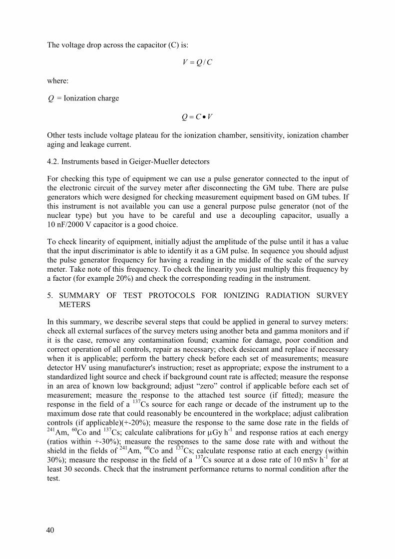
QC test procedures for nuclear counting systems have been elaborated in work carried out at the Jülich Research Centre’s (FZJ) Central Institute for Electronics, Germany, in collaboration with the IAEA (Paper 6). The test set-up and description of various QC tests for nuclear counting systems were presented. The major QC tests are: count accuracy, clock accuracy, integral and differential non-linearity, count-rate non-linearity and Chi Square test. The tests are described in the form of a “cooking book” using commercially available pulse generators but avoiding costly absolute test instruments such as time markers. A parallel counting system must therefore be used to observe any abnormal behaviour of the pulse generators in use. With these electronic tests it is possible to discover and/or identify a deficiency in a nuclear counting system. The Chi Square tests permit assessment of the overall stability of a single channel analyzer counting system by using a radiation source. The stability of a multi-channel analyzer system is implicit in the presented Full Width Half Maximum (FWHM) or energy resolution of the system and the Gaussian shape and shape ratio of the photo peak.
1.7. FUTURE/FURTHER NEEDS OF THE MEMBER STATES
According to the observations and comments of the participants in the TM, the future needs of Member States (MS) on QC test procedures will be oriented as follows:
(1) QC applied to the repair and maintenance of NI will be a key subject when the instruments are utilized in ISO certified areas.
(2) E-learning as a tool for QC in repair and maintenance of NI is necessary for the training of technicians and young engineers not familiar with these QC procedures.
(3) Online (Real time) monitoring of the NI parameters with interlock capacity will be useful in the future as a QC tool and will be implemented in new instruments.
(4) Remote diagnostic tools for testing and verification are desired for QC of complex and safety related nuclear systems, this is a new concept that will be widely applied in the future (Tele-maintenance).
1.8. CONCLUSIONS
The participants agreed that the main conclusions obtained through the TM were:
(1) International standards must be applied to QC test procedures in order to help MS gain the acceptance of others/clients to produce and use NI in a reliable and effective manner.
(2) QC in the frame of a QA plan allows the improvement of quality and reliability of manufactured products and opens possibilities for a new client market (for example,
6

users of environmental, monitoring systems, radiation protection equipment, Non Destructive Tests (NDT) systems, radiation protection equipment, etc.).
(3) Development of electronic test procedures including a precise description of test set up, as described in the presented papers would be of assistance to MS or users (examples: NDT equipment, environmental monitoring systems, etc.).
(4) QC can only be completed by trained staff and with proper test instruments installed. Bilateral collaboration and sharing of experience are valuable tools to help MS achieve the required capability to make QC tests of NI. The above mentioned needs can also be met through CRP, technical meetings, training, etc.
(5) Not all NI are fully covered by active national or international standards. The main reason for this is the rapid recent technological developments.
(6) Some available standards have already been revised and updated; however, there are standards which still need to be updated in order to meet current requirements.
(7) IAEA involvement helps international standard organizations update quality control standards related to NI.
(8) The operation of nuclear counting systems can be assessed from the QC results obtained in the application of proper test procedures.
(9) QC tests should be software driven to avoid human errors in data logging. This feature can now be easily implemented in software driven NI to perform automated data-storage for later data traceability as required by ISO certification. The Chi Square value (as given in the IAEA-TECDOC-602) is an overall indicator for stability behaviour in a counting system and needs to be applied prior to use of NI.
(10) During the process of design/modernization/refurbishment of NI, QC tests procedures and their monitoring are required to achieve the desired specifications.
7


PRESENTATIONS

INTERNATIONAL STANDARDS AND QUALITY CONTROL PROCEDURES APPLIED TO NUCLEAR INSTRUMENTS
P. URBAŃSKI Institute of Nuclear Chemistry and Technology, Warsaw, Poland
Abstract The survey of international standards related to Nuclear Instrumentation and QC tests was presented.
From among the 29’336 active international standards published by such organizations as ISO, IEC, CEN and CENELEC, only 582 are devoted to nuclear instruments. The international classification of standards (ICS) is shown. Also, the list of 582 international standards related to nuclear instruments is attached.
1. INTRODUCTION
International standards play a very important role in QC management. Many basic QC procedures are included in the international standards and it appears that the primary duty of those responsible for the quality of a product or service is to comply with requirements included in the standards.
Nuclear instruments are a rather specialized topic, as they must meet not only general requirements concerning QC, but also strict rules related to ionization radiation. The list presented below contains only those international standards, which refer to products and services related to ionization radiation.
From among several tens of thousands of international standards, about five hundred connected with ionization radiation were found. The list was arranged according to International Classification of Standards (ICS). In the detailed information one can find a short abstract, number of pages and price. Generally the international standards are available through the national committees for standardization in each country.
In some cases the same standard may be mentioned twice, under different ICS codes. This is due to the fact that it is sometimes difficult to express the subject of a standard with a single ICS code. Also some CEN standards are identical or based on ISO standards. In these cases, the ISO standard number is used but preceded by the letters ‘EN’.
It is hoped that the presented list will assist persons and organizations developing nuclear instruments to find appropriate standards and apply recommended test procedure to assure QC of the devices produced and services offered.
2. ORGANIZATIONS DEVELOPING INTERNATIONAL STANDARDS
There are several organizations developing international standards (Table 1). TABLE 1. ORGANIZATIONS DEVELOPING AND PUBLISHING INTERNATIONAL
STANDARDS.
I S O International Organization for Standardization
I E C International Electrotechnical Commission
C E N European Committee for Standardization
CENELEC European Committee for Electrotechnical Standardization
ETSI European Telecommunication Standards Institute
11
ISO is a network of the national standards institutes of 154 countries on the basis of one member per country. ISO’s International Standards and deliverables support, among other things, improvement of quality, safety, security, environmental and consumer protection [1].
IEC is the leading global organization that prepares and publishes international standards for all electrical, electronic and related technologies. One of the main IEC’s objectives is to assess and improve the quality of products and services covered by its standards [2].
CEN, CENELEC and ETSI are three standardization bodies recognized as competent in the area of voluntary technical standardization. Together they prepare European Standards and make up the “European Standardization System”.The European Standards (EN’s) must be transposed into national standards and conflicting standards should be withdrawn [3-4].
The number of international standards published by the above mentioned organizations and still active at the end of 2006 is shown in Table 2.
TABLE 2. INTERNATIONAL STANDARDS ACTIVE AT THE END OF 2006.
ORGANIZATION TOTAL NUMBER OF STANDARDS
STANDARDS RELATED TO NUCLEAR INSTRUMENTS
ISO 16’455 222
IEC 5075 269
CEN 12’679 81*)
CENELEC**) 5127
Total 39’336 572
*) 25 standards are identical to or based upon ISO’s **) 84% of CENELEC standards are identical to or based upon IEC’s
3. INTERNATIONAL CLASSIFICATION FOR STANDARDS (ICS)
To compare international standards published by the various organizations and related to the different subjects, the international classification of standards was adopted. This meant that each main subject was allocated a two digit (Table 3.). The subject’s main code was then further divided into more detailed sub-categories to more precisely define the field of application of a standard.
Tables 3 and 4 show codes of both the main subjects and the sub-categories under which one can find international standards related to nuclear instruments.
The list of 582 international standards for nuclear instruments is attached to this document.
4. CLOSING REMARKS
⎯ One of the most important conditions of good QC management is to meet procedures from appropriate international standards.
12

⎯ In addition to general requirements concerning particular fields of application, the nuclear instruments have to fulfill requirements connected with using ionization radiation.
⎯ There are about 500 active international standards related to nuclear instruments and services and published by various organizations.
⎯ It is hoped that the presented list of collated standards may be of use for producers of nuclear instruments by enabling them to find and match appropriate standards to devices produced.
TABLE 3. LIST OF INTERNATIONAL CLASSIFICATION OF STANDARDS CODES.
01 GENERALITIES. TERMINOLOGY. STANDARDIZATION. DOCUMENTATION.
03 SOCIOLOGY. SERVICES. COMPANY ORGANIZATION AND MANAGEMENT. ADMINISTRATION. TRANSPORT
07 MATHEMATICS. NATURAL SCIENCES
11 HEALTH CARE TECHNOLOGY
13 ENVIRONMENT. HEALTH PROTECTION. SAFETY
17 METROLOGY AND MEASUREMENT. PHYSICAL PHENOMENA
19 TESTING
21 MECHANICAL SYSTEMS AND COMPONENTS FOR GENERAL USE
23 FLUID SYSTEMS AND COMPONENTS FOR GENERAL USE
25 MANUFACTURING ENGINEERING
27 ENERGY AND HEAT TRANSFER ENGINEERING
29 ELECTRICAL ENGINEERING
31 ELECTRONICS
33 TELECOMMUNICATIONS. AUDIO AND VIDEO ENGINEERING
35 INFORMATION TECHNOLOGY. OFFICE MACHINES
37 IMAGE TECHNOLOGY
39 PRECISION MECHANICS. JEWELLERY
43 ROAD VEHICLE ENGINEERING
45 RAILWAY ENGINEERING
47 SHIPBUILDING AND MARINE STRUCTURES
13

49 AIRCRAFT AND SPACE VEHICLE ENGINEERING
53 MATERIALS HANDLING EQUIPMENT
55 PACKAGING AND DISTRIBUTION OF GOODS
59 TEXTILE AND LEATHER TECHNOLOGY
61 CLOTHING INDUSTRY
65 AGRICULTURE
67 FOOD TECHNOLOGY
71 CHEMICAL TECHNOLOGY
73 MINING AND MINERALS
75 PETROLEUM AND RELATED TECHNOLOGIES
77 METALLURGY
79 WOOD TECHNOLOGY
81 GLASS AND CERAMICS INDUSTRIES
83 RUBBER AND PLASTICS INDUSTRIES
85 PAPER TECHNOLOGY
87 PAINT AND COLOUR INDUSTRIES
91 CONSTRUCTION MATERIALS AND BUILDING
93 CIVIL ENGINEERING
95 MILITARY ENGINEERING
97 DOMESTIC AND COMMERCIAL EQUIPMENT. ENTERTAINMENT. SPORTS.
TABLE 4. NUMBER OF INTERNATIONAL STANDARDS RELATED TO NUCLEAR INSTRUMENTS.
ICS code Subject ISO IEC CEN
01.040 Vocabularies - 4 -
11.040 Medical equipment - 74 -
11.80 Sterilization and disinfection 5 - 5
14

13.030 Waste 4 - 1
13.040 Air quality 1 - -
13.060 Water quality 4 - -
13.110 Safety of machinery - - 4
13.220 Fire protection 2 - -
13.280 Radiation protection 47 50 3
17.240 Radiation measurement 48 49 -
19.100 Non-destructive testing 13 - 28
25.160 Welding, brazing and soldering - - 16
25.220 Surface treatment and coatings 3 - 3
27.120 Nuclear energy engineering 52 91 -
37.040 Photography 11 1 -
67.020 Processes in the food industry 6 1 1
67.200 Edible oils and fats - - 1
71.040 Analytical chemistry 26 - 2
75.080 Petroleum products in general - - 4
75.160 Fuels - - 3
77.040 Testing of metals - - 3
77.120 Non-ferrous metals - - 1
77.160 Powder metallurgy - - 1
REFERENCES
[1] www.iso.org [2] www.iec.ch [3] www.cen.eu [4] www.cenelec.org
15


QUALITY ASSURANCE PLAN FOR GAS FILLED DETECTOR MANUFACTURING
C. G. HOFER, M. E. MILLER, S. I. THORP, I. MARTÍNEZ Instrumentation and Control Department, Comisión Nacional de Energía Atómica, Buenos Aires, Argentina
ABSTRACT Several Quality Control (QC) procedures related to gas filled detector manufacturing are presented. These
procedures were applied to end control of gamma ionization chambers, compensated ionization chambers, fission counters and wide range of chambers detectors. In addition, some reports with test results are included.
OBJECTIVE The objective of this work is to present a brief description of quality control procedures related to gas
filled detectors manufacturing.
1. INTRODUCTION
Three years ago, a project related to the design, development and manufacturing of several types of gas filled detectors was executed by the Instrumentation and Control Department.
The client was INVAP, who was constructing a reactor for ANSTO in Australia and was therefore also responsible for installing the detectors in the nuclear reactor.
In this case, the detectors were manufactured by the private sector through a technology transfer contract.
The whole project involved the provision of 19 detectors. The type of detectors provided and also covered by this presentation include compensated ionization chambers for the measurement of neutron flux in the power range, fission counters to measure neutron flux at start up, wide range fission chambers (Campbell detectors) to measure neutron flux all over the range and gamma ionization chambers to measure thermal power through the detection of 16N in water.
A quality assurance plan was established at the beginning of the project. This plan included, among others items, quality control procedures applied to the end test of the detectors to ensure their proper behaviour before release to the client.
All the procedures were developed in accordance with the irradiation facilities available in the Ezeiza Atomic Centre (SSDL and Research Nuclear Reactor).
The procedures related to measurements of background current, isolation tests, capacitive coupling and operative tests of each type of detectors. A procedure to verify the peak stability in fission counters was also included.
The Quality Plan developed for the manufacture of these detectors, quality control procedures and test results including graphs resulting from the peak stability test, are presented in this paper.
17

2. DESCRIPTION OF PROCEDURES
All the procedures presented have the following structure: objective, scope, notation and definitions, references, responsibilities, development, reports and annexes. The development section contains a list of instruments, a connection diagram to be used in the test and the criteria that must be met.
Procedures for isolation between electrodes and case are based on an electrometer in impedance mode and are adapted in accordance with the number of electrodes of each detector.
In order to determine that a proper connection between each electrode and its connector exists, a capacitive coupling measurement is made between the bias and signal connectors. If a fast variation in the bias voltage is introduced, because of the inter-electrode capacitance of the detector, a current pulse can be detected with an electrometer in the current mode.
This procedure is adapted in accordance with the number of electrodes of the detector.
The background current is measured biasing the detector as indicated in the corresponding data sheet and without radioactive sources. This current is measured with an electrometer in current mode.
For fission chambers, the air-tightness of the chamber is controlled via the peak stability. Two spectra are obtained for the same detector under the same conditions with at least one week delay. If there is no shifting of the peak, the air-tightness of the detector is considered adequate.
The operating test for each kind of detector is described below:
2.1. Gamma ionization chambers
This test is made in a SSDL (Secondary standard dosimetry laboratory), where a source with a known dose rate is available for the tested detector. The gamma sensitivity is then obtained as
( ) HIIS bkg /−=
where:
⎯ I = Measured current under irradiation ⎯ bkI = Background current
⎯ H = Dose rate.
2.2. Neutron detectors
For tests concerning neutrons, a paraffin wax block is used to moderate neutron energy emitted by the source in order to obtain thermal neutrons with energies below 0.4 eV. The moderator block has two wells; one used to allot the neutron source and the other to allot the reference detector or the detector under test.
18

A reference chain (reference detector, preamplifier, spectroscopy amplifier, high voltage power supply and multi-channel analyzer) is used to determine the neutron flux at the detector well in the moderator block. The MCA ROI control is adjusted to count only pulses occurring due to neutrons.
For fission counter and wide range chamber detectors in pulse mode operational test, the reference detector is replaced by the fission counter or wide range detector and the neutron sensitivity calculated as:
NCRCFN NNS Θ⋅= /
where:
⎯ NS = Neutron sensitivity of fission counter or wide range detector in pulse mode
⎯ CFN = Total Neutron count rate of fission counter or wide range detector
⎯ NΘ = Neutron flux on detector position.
For wide range detector in fluctuation mode, neutron sensitivity is calculated as:
fKIS NN Δ⋅⋅Θ= /2
where:
⎯ NS = Neutron sensitivity in fluctuation mode ⎯ 2I = Detector current in fluctuation mode ⎯ NΘ = Neutron flux on detector position (as calculated for reference detector in pulse
mode) ⎯ K = Fluctuation chain transference ⎯ fΔ = Filter band width.
In this test, the detector output is measured by a RMS voltmeter. The measurement chain includes a current to voltage converter/amplifier1, a band pass filter and a RMS voltmeter.
For wide range detector in current mode, neutron sensitivity is calculated as:
⎯ NS = Neutron sensitivity in current mode ⎯ I = Detector current in current mode ⎯ NΘ = Neutron flux on detector position (as calculated for reference detector in pulse
mode).
1 Low noise, wide band amplifier
19

For ionizations chambers operational test, neutron sensitivity is calculated as:
NBGDON IIS Θ−= /
where:
⎯ NS = Neutron sensitivity
⎯ OI = Detector current
⎯ BGDI = Background detector current
⎯ NΘ = Neutron flux on detector position (as calculated for reference detector in pulse mode).
And Gamma sensitivity as:
XIIS o 2/)( γγγ −=
where:
⎯ γS = Gamma sensitivity
⎯ γI = Detector gamma current
⎯ oIγ = Background detector gamma current in two positive HV bias configuration
⎯ X = Gamma field. This test is realized in SSDL facilities.
For compensated ionization chambers (CIC), the Degree of no Compensation is measured as:
po IIDNC /=
where:
⎯ DNC = Degree of no compensation ⎯ oI = CIC output current in normal bias configuration
⎯ pI = CIC output current in two positive HV bias configuration.
In addition, the resulting test records for all the detectors are included as well as the peak spectrum for fission counters for air-tightness verifications.
3. CONCLUSIONS
Quality Control in the framework of a Quality Assurance plan allows improved quality of our products and broadens the market for potential new clients to include provision of our Nuclear Instrumentation to Nuclear Power Plant operators.
20

A FAULT TREE FOR COMMON PROBLEMS WITH TLD READERS
M. LÓPEZ RODRÍGUEZ External Dosimetry Laboratory, Center for Radiation Protection and Hygiene, Cuba.
ABSTRACT Thermo Luminescence Dosimeters (TLD)’s are commonly used for routine dosimetry in many nuclear
installations of the Member States. TLD readers are, for example, an important part of the Cuban Radiation Protection System in which more than 8000 workers are monitored. The proper maintenance and troubleshooting of this type of instrument could be a critical item in the national radiation protection system particularly in developing countries where available resources are limited. This paper presents procedures specifically designed to provide maintenance and troubleshooting of TLD readers. The test procedures on TLD readers are animated and include a general troubleshooting tree showing all possible failures and solutions for any type of TLD readers. The paper also includes the service manual for the equipment. The procedures presented may be useful for MS to help them solve failures in this kind of equipment.
1. INTRODUCTION
Dosimetry for radiation protection in nuclear environments routinely uses several different means. These means include photographic films, thermo-luminescence detectors, TLDs and direct reading dosimeters. TLDs are commonly used in many nuclear installations of the Member States. TLDs require use of a delicate piece of equipment, the TLD reader, in order to get the dose information. This equipment has a certain degree of complexity. Proper maintenance and troubleshooting of these instruments are critical, considering that this equipment is integral to the national radiation protection systems of developing countries.
Quality Control test procedures for the proper maintenance and troubleshooting of TLDs have been developed in the External Dosimetry Laboratory of the Center for Radiation Protection and Hygiene (CPHR), Cuba. The TLD readers are an important part of the Cuban Radiation Protection System which monitors more than 8000 workers.
The developed test procedures are animated and provide a useful tool as they also show a general troubleshooting tree, with all possible failures and solutions for any type of TLD readers.
2. BASIC PRINCIPLE OF TLDS
Thermo-luminescence, TL, (thermo means heat and lumen means light) is the ability of some materials to convert energy from one radiation wavelength to another radiation wavelength, normally in the visible light range, after the application of heat [1].
As a result of irradiation, some solid substances undergo changes in certain physical properties. These changes can reflect the storage of energy absorbed from the received radiation. If this is true and we can recover the stored information, these materials can be used as dosimeters, in particular as personal dosimeters due to their size, reliability, response, etc.
2.1. Electron traps
Electrons in some solids can exist in two energy states, a lower energy state called the valence band and a higher energy state called the conduction band. The difference (energy region) between the two bands is called the band gap and is different for every element or compound. Normally in a solid, no electrons exist in energy states contained in the band gap. This is a
21

forbidden region. In some materials, defects in the material exist or impurities are added that can trap electrons in the band gap and hold them there.
2.2. Thermo-luminescence photon
These trapped electrons represent stored energy for the time that the electrons are held. This energy is given up (emitted as light photons when the material is heated up) as the electron returns to the valence band, this is the Thermo-luminescence Photon.
2.3. TLD readers
The function of a TLD reader is basically the heating of the TLDs to a well defined temperature by any means and afterwards, the precise measurement of the emitted light.
3. ANIMATED PROCEDURES FOR MAINTENANCE AND REPAIR
The procedures were designed to provide proper maintenance and troubleshooting of this kind of instruments. The procedures include sections that consider: Test conditions, test instruments employed, background radiation, radioactive sources employed, temperature, test circuits and measurements. The main screen is shown in the Fig. 1.
Fig. 1. Main screen of the developed QC procedures for maintenance and troubleshooting of TLD readers.
3.1. Main components of the TLD readers
In order to understand the operation of the TLD readers, it is fundamental that the users and the service engineers have a good knowledge of the main components of the equipment. Fig. 2 shows these components in some detail.
22

Fig. 2. TLD main components.
The equipment is automated to operate continuously if necessary. The TLD pellet needs to be fixed in the measuring position. The Heating System then uses heated gas to raise the temperature in a controlled way with a temperature reference profile. The Photo-multiplier Tube (PMT) gain is maintained as a constant in the Light Measuring System, taking a light reference as the reference point. A block diagram of the system [2] is shown in Fig. 3.
3.2. The fault tree for troubleshooting
In the RADOS TLD reader [3] possible failures are classified into 6 main problems. Fig. 4 illustrates the six branches that can be followed in order to solve the failure. An important starting point for troubleshooting is identification of the symptoms.
It is assumed that if the fault tree is followed carefully, the equipment can be repaired. A lot of technical information is included: the User Manual [4] and several specific instructions for: TLD Calibration, Thermocouple, the Heating System, Temperature Reference Profile, Temperature Measuring System, Power Supplies, Power Supplies Circuit, Power Control, Photomultiplier Tube (PMT), Main Key, Light Reference System and Light Filter, Light Measuring System, High Voltage Divider, High Voltage Circuit, Gas Heating, Fuse and Line Filter, Cold Junction, Checking the Power Control, Checking the PMT, Checking the Current to Frequency System, Building a TLD Reader and Automated System TLD RADOS.
23
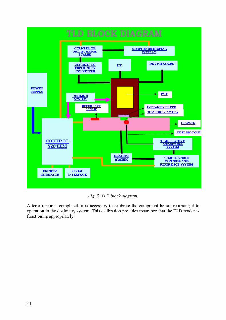
Fig. 3. TLD block diagram.
After a repair is completed, it is necessary to calibrate the equipment before returning it to operation in the dosimetry system. This calibration provides assurance that the TLD reader is functioning appropriately.
24

Fig. 4. General Fault Tree for Common Problems with TLD Readers.
4. REQUIREMENTS FOR USE OF THE PROCEDURES
4.1. Software
Platform: Window 98, 2K, ME, XP.
Reader: Adobe Acrobat Reader 5.0-7.0
4.2. Hardware
⎯ a.- Multimedia. ⎯ b.- CD Reader. ⎯ c.- 80 Mbytes of necessary space in HDD.
5. CONCLUSIONS
The presented animated procedures were designed specifically to help in the maintenance and repair of TLD readers and can be useful for MS to help them solve failures in this type of equipment.
25

REFERENCES
[1] BECKER, P., TLD Manual, IRD, Brazil (2002). [2] Information obtained by interchange with RADOS Finland (2001–2006). [3] RADOS, The Service Manual RE-1, Finland (1989). [4] HARSHAW, The Service Manual HARSHAW 2000, (1987).
26
QC TEST ON RADIATION DETECTORS AND THE ASSOCIATED NUCLEAR COUNTING SYSTEMS
F. J. RAMÍREZ-JIMÉNEZ, L. MONDRAGÓN-CONTRERAS, P. CRUZ-ESTRADA Instituto Nacional de Investigaciones Nucleares (ININ), La Marquesa, Ocoyoacac, Mexico.
ABSTRACT Quality Control (QC) tests on radiation detectors and the associated nuclear counting systems is required
because in many cases the results obtained in radiation measurement are related to critical processes like: radiological protection, industrial processes, human health and even national safety. The radiation detector QC tests guarantee proper operation, avoiding the possibility to get false pulses due to, for example, noise, high voltage failures, interference pick-up, leaking, etc. Generally the tests are based on IEEE/ANSI standards but in some cases special detectors and special operation conditions are not fully covered in these standards. The QC tests of associated nuclear counting systems are related to the assurance of the exact counting and the accuracy of the timing gate employed in the counting. We are reviewing all the available standards related to this goal and elaborating test procedures considering the use of common test tools such as: digital multimeters (DMM), NIM counter/timers, frequency meters, pulse generators, power supplies, oscilloscopes, NIM crates. A case study is presented for the saturation behaviour of Geiger-Mueller detectors in strong radiation fields.
1. INTRODUCTION
Quality Control tests on radiation detectors and the associated nuclear counting systems is required because in many cases the results obtained in radiation measurement are related with critical processes like: industrial processes, radiological protection, human health and even national safety. The radiation detector QC tests guarantee proper operation, preventing the possibility of wrong results, for example, when we count false pulses due to noise, high voltage failures, interference pick-up, leaking, etc. Generally these tests are based on established IEEE/ANSI standards. The QC tests of associated nuclear counting systems are related to the assurance of the exact counting and the accuracy of the timing gate employed in the counting. We are reviewing all the available standards related with this goal and elaborating test procedures considering the use of common test tools such as: digital multimeters (DMM), NIM counter/timers, frequency meters, etc. A case study is presented for the saturation behaviour of Geiger-Mueller detectors in strong radiation fields. This provides an example of special conditions of operation that are not fully covered by the conventional standards.
2. ESTABLISHED STANDARDS
Several IEEE/ANSI standards related to testing of radiation detectors are being reviewed, they are listed in the references section, [1-8]. We have found that in some cases, special detectors and special conditions are not fully covered by these standards. Test procedures are being elaborated to consider the use of common test tools such as: digital multimeters (DMM), NIM counter/timers, frequency meters, pulse generators, power supplies (laboratory power supplies and high voltage power supplies as used to bias detectors), oscilloscopes, NIM crates with power supply, etc., and applying the recommendations of the ISO/IEC 17025 standard.
3. THE GEIGER-MUELLER DETECTOR REVISITED
The Geiger-Mueller (GM) detector remains a commonly used device for measurement of radiation. Despite also being one of the more studied devices [9], there is little in the literature about the saturation behaviour of the GM detector under strong radiation fields. Strong radiation fields are commonly found in many nuclear installations. An example of this is
27

nuclear power plants where GM detectors are widely employed to monitor process variables like the radiation emitted in gaseous effluents, liquid effluents, steam lines, etc. That is the reason for this presentation of a study of the saturation behaviour of GM detectors in strong radiation fields.
The GM detector has a limitation in its counting capabilities even in low intensity radiation fields. This is due to the recovery time needed to regain its original electrical condition after an interaction in its sensitive volume. This time is called dead time because during this time the detector is almost insensitive to radiation.
3.1. Measurement of the dead time
The dead time of the GM detector is measured in normal conditions, with the test circuit recommended by the manufacturer (see Fig. 1.a). An optimal bias voltage of 900 V is used and a moderate gamma radiation field with an exposure rate of 10 mR/hr is applied.
Fig. 1. Dead time measurement. a) (Left) Biasing circuit; b) (Right) Pulses obtained for the LND 721detector, the settings of the oscilloscope are: 20 V/div and 50 μs/div.
The pulse obtained has a peak voltage of 75 V, and the dead time is 130 μs (see Fig. 1.b). The second pulse is smaller than the former one because the detector is still recovering its normal condition. If the sensitivity of the detector is 45 counts per second/mR/hr, the detector could work with a pulse repetition rate that corresponds to an exposure rate up to 170 mR/hr [10].
3.2. Saturation behaviour
Under strong radiation fields the GM detector suffers counting losses as well as an increase in the conduction of DC current through the detector. This increment in the current could reduce the size of the pulses due to both the loading effect in the circuit and in the bias power supply.
28

3.2.1. Counting loss
The pulses obtained from the circuit of Fig. 1.a) with a 137Cs source are recorded in an oscilloscope to observe the effect when we increase the exposure rate from 10 mR/hr to 92 R/hr. The results are shown in Fig. 2 and Fig. 3. The reduction in the size of the pulses can be clearly seen.
Fig. 2. G-M pulses obtained for an exposure rate of: a) (Left) 10 mR/h, the settings are: 20 V/div, 10 ms/div. b) (Right) 103 mR/hr, the settings are: 20 V/div, 2.5 msdiv.
Fig. 3. G-M pulses obtained for an exposure rate of: a) (Left) 3.7 R/h, the settings are: 20 V/div, 2.5 ms/div; b) (Right) 92.7 R/hr, the settings are: 10 V/div, 2.5 ms/div.
Afterwards, the pulses are applied to a discriminator/counter through a preamplifier (see Fig. 4.a). The obtained variation in the counting with the increase of the exposure rate is shown in Fig. 4.b). The detector has an experimental linear response up to 170 mR/hr, and this limit is in concordance with the estimated limit based on the obtained value of dead time.
29

Fig. 4. Measurement of the counting loss. (a) (Left) Circuit employed; (b) (Right) Counting vs. Exposure rate.
3.2.2. Increase of the detector current
The voltage measured in R1 (see Fig. 1.a) shows the variation of the current in the detector and was recorded with an oscilloscope in order to observe the effect of increasing exposure rates from 150 mR/hr to 35 R/hr (see Figs. 5 and 6). The current was calculated by Ohm’s Law. Finally, the maximum value was 12 μA for an exposure rate of 1 R/hr (see Fig. 7). The increase in the DC current is clearly seen.
Fig. 5. GM pulses obtained for an exposure rate of: a) (Left) 150 mR/h, the settings are: 20 V/div, 1 ms/div.; b) (Right) 500 mR/h., the settings are: 20 V/div, 250 μs/div.
30

Fig. 6. GM pulses obtained for an exposure rate of 35 R/h, the settings are: 20 V/div, 250 µs/div.
Fig. 7. Increment of the current in the GM detector due to the increase of the exposure rate.
Special GM detectors exist for high radiation fields and the difference in behaviour at high exposure rates could be quite different, see Fig. 8.
31

Fig. 8. Comparison between the responses of a GM detector specially designed for high exposure rates (LND716) and a normal detector (LND 719).
4. CONCLUSIONS
QC tests on radiation detectors and the associated nuclear counting systems are necessary to guarantee the proper operation of the measuring chain in critical systems. Established standards that could be applied do exist, however, some new detectors and special operating conditions are not fully covered by these standards. Also, practical experiences are not included in the existing procedures. The elaboration of more practical test procedures could help Member States to apply QC tests to their nuclear equipments.
The example shown illustrates that GM detectors need to be carefully selected for high count rates. They could produce large errors, which may go unnoticed in radiation fields with a wide range of variation as frequently occurs in some nuclear installations.
REFERENCES
[1] ANSI/IEEE Std 398™-1972(R2006), IEEE Standard, Test Procedures for Photo-multipliers for Scintillation Counting and Glossary for Scintillation Counting Field.
[2] ANSI/IEEE Std 759-1984, IEEE Standard Test Procedures for Semiconductor X Ray Energy Spectrometers.
[3] NSI N42.14-1999, (Revision of ANSI N42.14-1991), American National Standard for Calibration and Use of Germanium Spectrometers for the Measurement of Gamma-Ray Emission Rates of Radio-nuclides.
[4] IEEE Std 300-1988(R2006), (Revision of IEEE Std 300-1982), IEEE Standard Test Procedures for Semiconductor Charged-Particle Detectors.
[5] ANSI N42.25-1997, American National Standard Calibration and Usage of Alpha/Beta Proportional Counters.
[6] ANSI N42.31-2003, American National Standard for Measurement Procedures for Resolution and Efficiency of Wide-Band-gap Semiconductor Detectors of Ionizing Radiation.
32

[7] ANSI N42.13-1986, American National Standard, Calibration and Usage of Dose Calibrator Ionization Chambers for the Assay of Radio-nuclides.
[8] IEEE Std 309™-1999, N42-3-1999(R2006), (Revision of IEEE Std 309-1970, ANSI N43-1969), IEEE Standard Test Procedures and Basis for Geiger-Mueller Counters.
[9] KNOLL G. F. “Radiation, Detection and Measurement” John Willey and Sons, Third edition (2000).
[10] RAMIREZ-JIMENEZ F. J., TORRES-BRIBIESCA M. A “Medición de las Características de Saturación de un Monitor de Radiación con Detector Geiger-Mueller, INFORME TÉCNICO, IE-99-14 Departamento de Electrónica, Laboratorio de Detectores de Radiación, Instituto Nacional de Investigaciones Nucleares (ININ), Noviembre 1999.
33


QUALITY CONTROL TESTS FOR RADIATION SURVEY INSTRUMENTS
S.L.C. MDOE, Y.Y SUNGIT Tanzania Atomic Energy Commission, Tanzania
Abstract Research, medical, academic and industrial institutes utilizing nuclear technology in Tanzania have been
acquiring modern and costly scientific, analytical and technical equipment. Recent advancement in electronics and software means that desired functions can be activated or cancelled using an optional Windows-based operating program in many cases, resulting in precise measurements and reduced operator errors. Stored measured values can be accessed any time and displayed on the meter. Most of these complex survey meters, which are now becoming portable spectroscopy systems or source identifiers, are designed for multiple detector configurations that require software access to internal programs for adjustments, calibration and troubleshooting. Automation of critical adjustments makes it easy to set up with any detector, while minimizing the required operator expertise. Survey meters have been calibrated to measure the dose. These meters are highly specialized and can only be used for the type of radiation (X-rays, gamma rays, neutrons, etc.) for which they have been calibrated, if this condition is not observed, big errors could be included in the measurements, then radiation survey instruments should never be used to measure dose outside the energy range or type of radiation for which they were calibrated. This presentation discusses the quality control procedures for the tests of radiation survey meters. Procedures to be considered include, test of probes, connection of instruments, computer interconnections, test instructions, test procedures and calibration and preventive maintenance. The software automation and interaction have made critical adjustments easy to set up but the user needs to know the basic principles behind it.
1. INTRODUCTION
Instruments used for radiation survey monitoring are not necessarily required to provide extremely accurate results, but they must provide consistent indications of the presence or absence of ionizing radiation. Regulations impose duties on users to ensure that equipment used for monitoring levels of ionizing radiation is properly maintained and is suitable for the purpose for which it is intended, and is adequately tested and examined by qualified personnel at appropriate intervals (e.g., annually).
This presentation discusses the pre-calibration and quality control tests for radiation survey meters. The following procedure suggestions are not sufficient for complying with standards but are a good step in this direction. These suggestions include; Physical inspection; proper selection of test instruments, test conditions; tests of probes; test of connecting cables; proper function, test circuits and response. The procedures should also describe test of leakage current, detector aging, sensitivity, energy dependence, directional dependence, response time, overload characteristics and how to make test reports. All generated technical reports must have a unique and consecutive numbering sequence. The results and reports from tests of radiation survey meters should be registered and stored in a folder or archived in a computer for future reference.
2. IONIZING RADIATION SURVEY METERS
Ionizing survey meters are based on different types of detectors. Radiation survey meters are either gas filled detectors or scintillation based detectors. Depending upon design of the gas filled detector and the voltage applied between the two electrodes, the detector can operate in one of three regions, see Fig. 1.
35

Fig. 1. Gas filled detectors and counting plateau.
Depending upon the electronic circuit used, detectors can operate in a pulse mode or in the mean level or current mode [1]. Proportional and GM counters are normally operated in the pulse mode.
The ionization chambers convert the ionizing radiation in electrical charge and current. Therefore, the instruments based on ionization chambers for measuring exposure/dose are, basically current or charge meters. The range of the charges and currents produced by the ionization chambers is extremely small and therefore a special instrument called an electrometer is applied for their measurements. In charge method a possibility to measure the charge is to convert signal from dc to ac. This is accomplished using a dynamic capacitor of vibrating reed. Also, the charge (Q) can be calculated from the voltage (V) developed across a capacitor (C):
VCQ •=
It is possible to verify an electrometer using a “detector simulator”. In the case of ionization chambers, electrical current or charge are produced, then instead of applying pulses you need to apply current (dose rate) or charge (dose) with a current source [2]. This appears very simple but in reality is a little bit complicated since the values of the currents/charges involved with the applications of ionization chambers are in the range of 10-13 A and 10-13 C respectively. Working with such small values requires some special care.
Survey meters also can be made with scintillation detectors or semiconductor detectors. Certain organic and inorganic crystals contain activator atoms and emit scintillations upon absorption of radiation. Solid state detectors work on the principle that they collect the charge generated by ionizing radiation in a solid. These detectors are made of semi-conducting material and are operated much like a solid state diode in reverse bias condition. The applied high voltage generates a thick depletion layer and any charge created by the radiation in this layer is collected at an electrode. The charge collected is proportional to the energy deposited in the detector and therefore these devices can also yield information about the energy of individual particles or photons of radiation. The semiconductor detectors are made mostly from silicon or germanium.
36

3. PROPERTIES OF SURVEY METERS
3.1. Sensitivity
The sensitivity is defined as the response of the instrument to a radiation fields. Larger detector volumes or detectors with gases under high pressure have higher sensitivity. For example, a wide range of equivalent dose rates can be covered with ionization chamber based survey meters (e.g., 1 μSv/h-1 Sv/h).
Owing to finite resolving time, Geiger Mueller (GM) based systems would saturate beyond a few thousand counts per second. Low dead time counters or dead time correction circuits enable these detectors to operate at higher intensity fields. Scintillation based systems are more sensitive than GM counters because of a higher γ gamma conversion efficiency and dynode amplification. Their resolving time is quite low compared to GM counters.
3.2. Energy dependence
Survey meters are calibrated at one or more beam qualities, but are often used in situations in which the radiation field is complex or unknown. These survey meters should therefore have low energy dependence over a wide energy range. GM counters exhibit strong energy dependence for low energy photons (< 80 keV).
3.3. Directional dependence
By rotating the survey meter about its vertical axis, the directional response of the instrument can be studied. A survey monitor usually exhibits isotropic response, as required for measuring ambient dose equivalent, within 60 degrees to 80 degrees with respect to the reference direction of calibration, and typically has a much better response for higher photon energies (> 80 keV).
3.4. Response time
The response time of the survey meter is defined as the RC time constant of the measuring circuit, where R is the decade resistor used and C is the capacitance of the circuit. Low dose equivalence ranges would have high R and hence high RC values, and then the indicator movement would be sluggish. At least three to five time constants are required for the meter reading to stabilize.
3.5. Overload characteristics
Survey meters must be subjected to a dose rate of about ten times the maximum scale range to ensure that they read full scale rather than near zero on saturation.
3.6. Long term stability
Survey meters must be calibrated in a standard dosimetry laboratory with the frequency prescribed by the regulatory requirements of the country. Calibration should typically be conducted annually and also immediately after repair or immediately upon detection of any sudden change in response. The long term stability of survey meters must be checked at regular intervals using a long half life source in a reproducible geometry.
37

3.7. Pre calibration checks
Radiation survey meters should be calibrated with a radioactive source. Electronic calibration alone is not acceptable [3]. The following items should be observed before exposing the instrument to a source for adjustment and calibration: the instrument should be free of significant radioactive contamination; the meter should be adjusted to zero or a point specified by the manufacturer using adjustments provided; the batteries or power supply should comply with manufacturers specification for the instrument; the instrument should be turned on and allowed to warm up for the period specified by the manufacturer; electronic adjustments such as high voltage should be set, as applicable, to the manufacturer's specifications; geotropism should be known for orientation of the instrument in the three mutually perpendicular planes, and this effect should be considered during calibration and performance testing; the performance of any internal sampling time base in digital readout instruments should be verified as being within the manufacturer's specification.
3.8. Test instruments
The test procedures for radiation survey meters should consider the use of the following instruments: oscilloscope, pulse generator, frequency meter, power supplies (bench and HV power supplies), digital multimeter and counter/timer.
3.9. Test conditions
Test conditions should consider the background radiation, temperature and radioactive source employed.
4. TEST CIRCUITS
Manufacturer specifications and recommendations must always be followed. If not available some test circuits can be adopted for use in testing different types of survey meters. Refer to standard ANSI/IEEE test procedures [4] or NPL guide 14 (1999) for specific radiation detectors.
4.1. Instruments based in ionization chamber detectors
Radiation detectors consist of a chamber filled with air or gas, in which an electric field inside the detector is applied for the collection of charges associated with ions and electrons produced in the measuring volume of the detector by the ionizing radiation. An electrometer is used to measure very small electrical currents (in the range from 10-8 A to 10-15 A) or small electrical charges (in the range from 10-12 C to 10-15 C).
Sensitivity in ionization chamber detectors is the ratio between the current produced by an ionization chamber and the exposure rate, given for a radiation source. The isotope employed must be specified.
Fig. 2 shows some of the setups for testing ionization chambers [5].
38

Fig. 2. Ionization current measurement (electrometric method).
where:
⎯ E = Electrometer ⎯ R = Input resistance of electrometer ⎯ C = Capacitance of chamber. The voltage drop across resistance (R) is then,
RIV RR •=
Another alternative is to convert the signal from dc to ac in an early stage. This conversion is accomplished in the dynamic capacitor (C) or vibrating reed electrometer by collecting the ion current through RC circuit with long time constant, as shown in Fig. 3.
RVI R
R =
Fig. 3. Ionization current measurement (charge method).
39
The voltage drop across the capacitor (C) is:
CQV /=
where:
Q = Ionization charge
VCQ •=
Other tests include voltage plateau for the ionization chamber, sensitivity, ionization chamber aging and leakage current.
4.2. Instruments based in Geiger-Mueller detectors
For checking this type of equipment we can use a pulse generator connected to the input of the electronic circuit of the survey meter after disconnecting the GM tube. There are pulse generators which were designed for checking measurement equipment based on GM tubes. If this instrument is not available you can use a general purpose pulse generator (not of the nuclear type) but you have to be careful and use a decoupling capacitor, usually a 10 nF/2000 V capacitor is a good choice.
To check linearity of equipment, initially adjust the amplitude of the pulse until it has a value that the input discriminator is able to identify it as a GM pulse. In sequence you should adjust the pulse generator frequency for having a reading in the middle of the scale of the survey meter. Take note of this frequency. To check the linearity you just multiply this frequency by a factor (for example 20%) and check the corresponding reading in the instrument.
5. SUMMARY OF TEST PROTOCOLS FOR IONIZING RADIATION SURVEY METERS
In this summary, we describe several steps that could be applied in general to survey meters: check all external surfaces of the survey meters using another beta and gamma monitors and if it is the case, remove any contamination found; examine for damage, poor condition and correct operation of all controls, repair as necessary; check desiccant and replace if necessary when it is applicable; perform the battery check before each set of measurements; measure detector HV using manufacturer's instruction; reset as appropriate; expose the instrument to a standardized light source and check if background count rate is affected; measure the response in an area of known low background; adjust “zero” control if applicable before each set of measurement; measure the response to the attached test source (if fitted); measure the response in the field of a 137Cs source for each range or decade of the instrument up to the maximum dose rate that could reasonably be encountered in the workplace; adjust calibration controls (if applicable)(+-20%); measure the response to the same dose rate in the fields of 241Am, 60Co and 137Cs; calculate calibrations for μGy h-1 and response ratios at each energy (ratios within +-30%); measure the responses to the same dose rate with and without the shield in the fields of 241Am, 60Co and 137Cs; calculate response ratio at each energy (within 30%); measure the response in the field of a 137Cs source at a dose rate of 10 mSv h-1 for at least 30 seconds. Check that the instrument performance returns to normal condition after the test.
40

6. TEST OF MODERN IONISING RADIATION DETECTOR METERS
Recent advancement in electronics and software has provided new features in the radiation survey meters. Now in modern instruments desired functions can be activated or cancelled using an optional Windows-based operating program, resulting in precise measurements and reduced operator errors. Stored measured values can be accessed any time and displayed on the meter. Most of these complex survey meters which are now becoming portable spectroscopy systems or source identifiers were designed for multiple detector configurations that required software access to internal programs for adjustments, calibration and troubleshooting. Automation of critical adjustments makes it easy to set up if we decide to change the type of detector, while minimizing the required operator expertise. There is several easy-to-use digital hand held multi-channel analyzers available on the market, ideally suited for: detection of illicit radioactive source trafficking. Other Responder Applications are fire fighters, law enforcement, hospital emergency personnel, Customs and Border Controls, Waste (scrap) Applications, Health Physics Applications which need isotope specific results, In Situ Environmental Screening, Treaty and Non-proliferation, Compliance, Monitoring of Nuclear Transportation. They can be used for any field measurement application requiring dose and count rate measurements, locating sources, nuclide identification with activity measurements, and spectrum acquisition and analysis. All these modes of operations could be easily selectable with only one touch on the screen.
All these new equipments give results not just data! The information is continuously updated about radiation hazards such as: identified nuclides, nuclide activities or dose rate. They also provide a flexible application with specific response by accommodating different detector/probe sizes and technologies. The high voltage power supply and preamplifier are built into each probe. These instruments automatically recognize each of these intelligent probes and select the associated calibrations settings and other parameters.
While this automation has made the surveys meters easy to use, testing of all combination of probes and the MCA counting chain is complex as all the controls are embedded (micro controller based) and not easily accessible for adjustment using communication with a PC by the USB port.
7. CONCLUSION
The establishment and application of an appropriate QA/QC programme in Nuclear Instrumentation as well as provision of quality repair and maintenance services in the Member States will result in significant impact in nuclear technology applications sector. This will need a system for testing, repair, maintenance, calibration and certification according to international standards. It will help introduce efficient procedures for testing and servicing nuclear instruments using easy to acquire and low cost tools.
REFERENCES
[1] KNOLL, G.F., Radiation Detection and Measurement”, Ed. John Wiley and Sons, USA (1979).
[2] ANSI/IEEE N42.13-1979 “ANSI Calibration and Usage of Dose Calibrator Ionization Chambers for the Assay of Radionuclides”, April 10, USA (1978).
[3] INTERNATIONAL ATOMIC ENERGY AGENCY, Calibration of Radiation Protection Monitoring Instruments, Safety Report Series No. 16, IAEA, Vienna 2000.
41

[4] IEC/CENELEC IEC 60731 “Dosimeter with Ionization Chambers as Used in Radiotherapy, British Standard, October 1997.
[5] TSOULFANIDIS, N, Measurement and Detection of Radiation, Ed. Hemisphere Publishing Corporation, USA (1983).
42

QUALITY CONTROL TEST FOR NUCLEAR COUNTING SYSTEMS
R. ENGELS1 and H. KAUFMANN2 1Zentralinstitut für Elektronik, Forschungszentrum Jülich, Germany 2International Atomic Energy Agency, Vienna, Austria
ABSTRACT The paper presents the test set-up for various QC tests for nuclear counting systems. The major QC tests
are described in this paper. These are: count accuracy, clock accuracy, integral and differential non-linearity, count rate non-linearity and chi square test. The tests are described in the form of a recipe book using commercially available pulse generators but avoiding costly absolute test instruments such as time markers. Therefore, a parallel counting system has to be used to observe any abnormal behaviour of the pulse generators used. With these electronic tests one is able to break-out and/or identify a deficiency in a nuclear counting system. The chi-square tests permit an assessment of the overall stability of a single channel analyzer counting system by using a radiation source, where the stability in a multi-channel analyzer system is presented in the FWHM resolution and the Gaussian shape and ratio of the photo peak.
1. INTRODUCTION
This paper was prepared to assist young engineers or technicians in their tasks on QC tests for nuclear counting systems. The described test procedures and test set-up were used over many years for comparison of commercially available nuclear counting systems as well as for nuclear spectrometers. Only the differential non-linearity (DNL) test set-up using a ramp generator created problems and was replaced by dial setting of pulse generator. The disadvantage of this method is that the limitation is given by the dial setting and the non-linearity of the used multi-turn potentiometer. A similar report was used in IAEA sponsored training courses or workshops and was well received by the participants.
Such systems can be operated in Pulse Height Analyzing (PHA) mode or in Multi-Scaling Counting (MSC) mode [1]. In PHA mode we distinguish between single channel analyzer (SCA) systems and multi-channel analyzer (MCA) systems. Only MCA can be operated in PHA or MSC mode.
Furthermore, this document provides information to utilize inexpensive test instruments such as pulse generators (only BNC Berkley pulse generators are suitable because of their specifications) and classical Nuclear Instruments Modules (NIM) such as a amplifier, SCA and counter/timer to compare a system under test with specified NIM modules of well known manufacturers (for example Canberra, Intertechnique, ORTEC, Silena, Tennelec, etc.). This technique avoids the utilization of the absolute but costly test instruments such as time markers and pulse generators (simulating a nuclear pulse coming from a detector) which are very precise in frequency and amplitude.
The procedures of the QC test are described as a recipe book for easier user understanding. In general, the following QC tests should be made to ensure proper operation of the counting system:
⎯ Count accuracy ⎯ Clock accuracy ⎯ Integral and differential non-linearity ⎯ Count rate non-linearity ⎯ Chi square test
43

In the following test set-ups, the system under test and the proper functioning NIM test electronic have to be connected all the time. If one of the inputs disconnects from the signal source (either pulse generator or preamplifier) the signal would change its amplitude and this would mislead the interpretation of results.
These test set-ups were used by the IAEA and others for many years, to monitor features of commercially available nuclear counting systems from well-known manufacturers, without complaints from the manufacturers when deficiencies were encountered by us.
The only exception was the use of ramp generators for testing the differential non-linearity. It was identified, during a workshop, that the differential non-linearity was very poor when using a ramp generator compared with the pulse generator dial setting method. Weak ground loops signals (not observable with oscilloscope) already influence this test method and therefore it is no longer presented in this set of test methods.
2. COUNT ACCURACY
All counts coming from the detector should be registered in the system under test. To observe this feature the following test set-up has to be used.
Fig. 1. Test set up for count accuracy determination.
The system under test and the specified NIM system (for example Canberra amplifier 2020, SCA 2030 and counter/timer 2071A) are simultaneously activated for counting, but the output pulses from the pulse generator were started later and manually and also stopped manually before the selected counting time was reached. This procedure ensures that all pulses can be registered. It must be noted that the SCA settings for both system under test and NIM test electronics should permit proper counting [2]. When a system under test is operated in a MSC mode all the contents of the various channels have to be summed up whereas in PHA mode the integral spectra can be taken. It is possible, that a system under tests does not register all incoming pulses due to updating which can block the registration of incoming pulses. Therefore, one has to make a set of measurements with different repetition rates of the pulse generator output. Due to dead time in a MCA system this frequency is limited. Furthermore, the system under test (MCA in PHA mode) has to be operated in real time mode. Try to
44

identify a frequency where the deviation is more than 0.3%, which can influence the interpretation of results.
NOTE: The NIM test electronic should have the same pulse shaping time as the system under test and should remain constant throughout all later tests. Table 1 below should present the results in the following way.
TABLE 1. COUNT ACCURACY.
Counting repetition rate
Contents of counter (NIM test electronics)
System under test
Deviation [%]
1 kHz 2 kHz 5 kHz 10 kHz 15 kHz
3. CLOCK ACCURACY
Clock accuracy is very important for a system applied to analytical measurements and therefore, it has to be tested. For systems which always use the same counting period (slicing a counting time and comparing the result with the previous counting period) this feature is of theoretical interest but does not influence the interpretation of results. All three systems (under test, NIM test electronic and reference counter) should be started almost simultaneously so that all systems see the same frequency jitter caused by the pulse generator.
The following test set-up has to be used to identify the clock or timing deviation.
Fig. 2. Test set up for clock accuracy measurements.
Pulses with a fixed repetition rate have to be registered in the system under test and in the NIM test electronic system consisting of amplifier, SCA and timer/counter. The deviation between the counter content of the NIM test electronic and the system under test is the clock error. A reference counter has to be used to observe whether the time base of the NIM test
45

electronics has a deviation, which would mislead the results. One count deviation is not an error; it is a result of the trigger mode in the used counters or/and time jitter of the applied time base in the system under test. The table below should present the results.
TABLE 2. CLOCK DEVIATION.
Repetition rate (Content of reference counter)
NIM test electronic System under test Clock deviation (%)
1 kHz (XXXX) 2 kHz (XXXX) 5 kHz (XXXX) 10 kHz (XXXX) 15 kHz (XXXX)
4. INTEGRAL AND DIFFERENTIAL NON-LINEARITY
4.1. Integral non-linearity
This feature of a nuclear instrument is only of importance when multiple energy lines have to be analyzed [2]. Test description:
The amplitude of the pulse coming from the pulse generator has to be increased until the counter starts counting. This amplitude setting of the pulse generator must be noted and registered. The lower level discriminator (LLD) setting should have an equal spacing to the next higher LLD setting. The spacing of the dial reading between two adjacent LLD settings has to be compared with the dial readings for two higher LLD levels’ settings. The deviation is the integral non-linearity.
Fig. 3. Set up for integral non-linearity measurements.
NOTE: LLD setting can be a dial setting like in SCAs module or digitally (when software driven) or in channels like in a MCA. In a MCA one considers the peak channel of the registered pulse.
46

The overall integral non-linearity of both (system under test and NIM test electronic) are presented in Table 3 and Table 3 and must be recorded with the dial setting for the output pulse of the pulse generator when the counter starts counting. This integral non-linearity is the sum of the amplifier and SCA. The test circuit is presented below.
TABLE 3. INTEGRAL NON-LINEARITY FOR SYSTEM UNDER TEST.
LLD setting (either digitally, dial setting or channel number)
Dial setting (amplitude) of pulse generator when counter started
Spacing between the dial settings of pulse generator
TABLE 4. INTEGRAL NON-LINEARITY OF THE NIM TEST ELECTRONIC.
LLD setting of SCA (LLD settings of SCA stated as an example)
Dial setting (amplitude) of pulse generator when counter started
Spacing between the dial settings of pulse generator
1.00 3.00 5.00 7.00 9.00
4.2. Differential non-linearity
Test description:
The amplitude of a pulse coming from the pulse generator has to be increased until the counter starts counting. This amplitude setting must be noted and registered. The amplitude of the pulse must then be increased until the counter stops counting and again the amplitude setting has to be noted and registered. The two amplitude settings have to be subtracted and compared with higher windows, which have to be equal.
NOTE: The window setting can be kept constant where applicable; only the LLD has to be increased. For SCA instruments, with only LLD and upper level discriminator (ULD), both levels have to be changed but the spacing has to be kept constant. From our experience one cannot use a ramp generator for this purpose.
The deviation is the differential non-linearity. In MCAs this deviation should be very small because a slight deviation in the channel width can result in different peak identification by modern spectrum evaluation software.
The test circuit is presented below and the data are presented in Tables 5 and 6.
47

Fig. 4. Set up for differential non linearity measurements.
NOTE: Window or spacing between ULD and LLD is constant.
TABLE 5. DIFFERENTIAL NON-LINEARITY OF THE SYSTEM UNDER TEST.
LLD setting (either digitally, dial setting or channel number)
Dial setting (amplitude) when counter started
Dial setting (amplitude) when counter stopped
Difference of the dial settings
TABLE 6. DIFFERENTIAL NON-LINEARITY OF NIM TEST ELECTRONIC.
LLD setting (either digitally, dial setting or channel number)
Dial setting (amplitude) when counter started
Dial setting (amplitude) when counter stopped
Difference of the dial settings
5. COUNT-RATE NON-LINEARITY
The observation of count rate non-linearity is of high importance when one assumes that during a measurement the count rate changes (deviation in count rate) which can lead to misinterpretation of the results.
48

This test must be performed using a random pulse generator. The preferred random pulse generator is the DB-2 from BNC Berkley. Signal processing specifications (shaping time) require that both systems, NIM test electronic and the system under test, must have nearly the same shaping time otherwise the result would be misleading. Higher count rate increases the probability of pile-up effects occurring which are not registered in a SCA system, because they are outside the SCA-window setting. In MCAs such events would be registered in a higher channel region. The reference counter/timer connected to the trigger out signal of the random pulse generator should verify when the NIM test electronic also loses count which will influence the interpretation of results. The test set-up with random pulse generator is presented below.
Fig. 5. Test set up for count rate non-linearity measurements.
NOTE: The count rate is not easy to adjust but should be within +/- 5%. To achieve this, check the count rate using only the reference counter with a one second measurement.
In addition, one has to make a set of measurements (total 5) in this test and average the counter contents. Table 7 shows the count rate non-linearity.
TABLE 7. COUNT RATE NON-LINEARITY.
Count rate Counter content of Reference counter
Counter content of NIM test electronic
System under test
Count rate non-linearity of the system under test (%)
100 cps 200 cps 500 cps 750 cps 1000 cps 1500 cps 2000 cps
49

6. PEAK SHIFT VERSUS COUNT RATE
Peak shift versus count rate appears to the user as equal to count rate non-linearity but electronically this is due to a poor baseline restoration. Therefore, this feature also has to be tested so that one knows about the behaviour of the base line restoration.
Test description:
In this set of measurements one has to monitor the peak position and peak shape. The pulse generator was set to the random mode and in the SCA system the LLD was set to a fixed level. When the counter starts counting, the dial setting for pulse amplitude of the random pulse generator has to be monitored by the dial setting for each count rate. The test set-up is presented below.
Fig. 6. Set up for peak shift versus count rate measurement.
TABLE 8. PEAK SHIFT VERSUS COUNT RATE.
Count rate
Dial setting of pulse generator when system under test starts counting
Deviation Dial setting of pulse generator when NIM test electronics starts counting
Deviation
200 cps 500 cps 1 kcps 2 kcps 10 kcps
7. CHI SQUARE TEST
This test is an overall QC test and gives an indication of the proper operation of the counting system when applying random pulses from a radioactive source. In a set of 10 measurements
50
the Chi Square test results should be within 3.325 and 16.919 as stated in the IAEA-TECDOC-602 [3].
When test results fall between the above boundaries it indicates that there are no instabilities in HV, SCA settings, amplifiers (base line shift or gain stability), counters (time base variations) nor any electronic influence coming either from ground loops, interference with radio power stations or control signals for electrical devices (1 kHz control signal). The chi square test is only dependant on the statistic pattern coming from a radioactive source.
The test set-up is presented below.
Fig. 7. Set up for chi square test.
The settings of the system under test and the NIM test electronic, shaping time, LLD and ULD have to be electronically the same. For each count rate a set of 10 measurements must be taken. The counter of the NIM test electronic and the system under test have to be started almost simultaneously to avoid deviation of the registered pulses, because they occur randomly in time.
An EXCEL document would help to calculate the chi square results. Only the 10 results have to be entered. All others are calculated by PC and can be filed in a database so that traceability is assured. An example is given below in Table 9. Table 10 presents the results of the set of measurements.
TABLE 9. EXAMPLE OF SPREADSHEET FOR CHI SQUARE TEST.
Number of measurement
Ci Ci-Cavr Square of (Ci-Caverage)
Sum of (Ci-Cav)2
Chi Square
1 60692 -89.2 7956.64 2 60679 -102.2 10444.84 3 60593 -188.2 35419.24 4 60668 -113.2 12814.24
51

Number of measurement
Ci Ci-Cavr Square of (Ci-Caverage)
Sum of (Ci-Cav)2
Chi Square
5 61076 294.8 86907.04 6 61063 281.8 79411.24 7 60959 177.8 31612.84 8 61033 251.8 63403.24 9 60547 -234.2 54849.64 10 60502 -279.2 77952.64 Sum 607812 Average 60781.2 460771.6 7.5808243
TABLE 10. CHI SQUARE RESULTS.
System under test NIM test electronics Count-rate
Average Count Number (Caverge)
Sum of the Squares (Ci-Caverage)
Chi Square result
Average Count Number (Caverge)
Sum of the Squares (Ci-Caverage)
Chi Square result
200 cps 500 cps 1000 cps 2000 cps
REFERENCES
[1] KNOLL, G.F., Radiation Detection and Measurement, John Wiley and Sons, New York (1979).
[2] BIRKS, J.B., The theory and Practice of Scintillation Counting, Pergammon Press, Oxford (1964).
[3] INTERNATIONAL ATOMIC ENERGY AGENCY, Quality Control of Nuclear Medicine Instruments. IAEA-TECDOC-602, IAEA, Vienna (1988).
52
QUALITY CONTROL OF NUCLEAR ADC’S WITH A NEW FPGA BASED PULSER
P.P. VAIDYA, M. VINOD, T.S. ANANTHAKRISHNAN, P.K. MUKHOPADHYAY Electronics Division, BARC, Trombay, Mumbai, India
ABSTRACT A precision and sliding pulse generator for quality control of nuclear ADC’s was developed using 16-bit
DACs and FPGA based design. For full scale pulse amplitude of 10 V, a minimum step size of nearly 150 µV can be obtained using 16-bit DACs. To reduce the step size further down to nearly 10 µV, an interpolation method was employed in sliding mode. The pulser has a stable output in the precision mode and is suitable for measuring the drift and temperature coefficient of nuclear ADC’s. It can also be used for testing the differential and integral nonlinearity of these ADC’s. It is expected that the pulser will be suitable for measurement of differential nonlinearity by ramped amplitude method without getting spurious values due to correlation effects. Procedures for performing these measurements have been described. The values of differential and integral nonlinearity can be found from the acquired histogram of the ADC output using a software program.
1. INTRODUCTION
Nuclear ADC is an important circuit block in Multi-channel Analyser (MCA). Performance of nuclear ADC should be tested to ensure proper working of MCA and spectroscopy system [1]. A prototype Nuclear Pulse Generator has been developed in three width NIM module which provides precision and sliding modes of operation with required controls. Use of mechanical switches and potentiometers on front panel has been avoided to achieve increased reliability. Parameters such as operational mode (precision/sliding), pulse amplitude, frequency, pulse duration, sweep period, etc., are entered using keypad and shown on LCD display. The pulse amplitude can be changed from 0 V to 10 V in steps of 150 µV for frequency variation from 1 Hz to 300 kHz. The pulse width can be changed from 1 µs to 1 ms. In sliding mode, sweep period can be set from 5 second to 1000 seconds.
The pulse generator is designed using a new interpolation technique along with dynamic offsetting which results in uniform amplitude distribution in sliding mode. Preliminary tests of this pulse generator indicate that it has temperature drift of less than 5 ppm/0C and INL of better than 0.01% FS. The pulser is thus suitable for quality control of Nuclear ADCs.
2. TEST PLAN FOR NUCLEAR ADC
Testing of Nuclear ADC includes basic functional tests and performance tests. Functional tests reveal whether the Nuclear ADC is functioning properly whereas performance tests reveal details regarding quality of Nuclear ADC.
During testing of a Nuclear ADC, test conditions should be noted properly. The test conditions include pulse generator settings such as working mode (Precision or sliding) pulse amplitude, frequency, pulse width, rise time and fall time, as well as ADC/MCA settings such as LLD, ULD, acquisition time, conversion gain, etc.
3. FUNCTIONAL TESTS
3.1. Dropped channel test
For this test the pulser is set in sliding mode to cover the entire range of ADC. Conversion gain is kept at maximum with LLD at minimum and ULD at maximum position.
Spectrum corresponding to uniform amplitude distribution is collected using pulse generator in sliding mode. It should be verified that for channels above LLD and below ULD there are
53

no channels with much less than average counts in spectrum. The few channels above LLD and few channels below ULD may however show some variations.
3.2. Conversion gain test
For this test the pulser is kept in precision mode with amplitude near the top of ADC range. For ADC settings, LLD is kept at minimum and ULD at maximum.
Initially conversion gain of ADC is kept at maximum. Counts are acquired for a fixed acquisition time. The peak channel position is noted. The conversion gain of ADC is then halved in steps till it reaches minimum value. For every setting of conversion gain the counts are acquired for same height of input pulse for fixed time. It should be checked that the acquisition channel number is also halved every time.
3.3. LLD test
This test reveals whether the Lower Level Discriminator circuit is working as per the specifications. The pulse generator is set in sliding mode. Pulse frequency, pulse width, rise time and fall time can be set as desired. Typically pulses with rise time of 0.5 µs, fall time of 2 µs, width of 2 µs and frequency of 10 kHz can be used.
ADC Conversion gain is kept maximum, LLD at minimum and ULD at maximum value.
With LLD at minimum setting, the spectrum corresponding to pulses with uniform amplitude distribution in sliding mode is acquired over full range of ADC. LLD is then increased in steps of 1 V and a spectrum is acquired corresponding to each setting of LLD. It is verified that there are no counts below expected LLD channel and that average counts are obtained in channels which are beyond LLD. Few channels above LLD and below ULD may show more variations.
3.4. ULD test
For this test the pulser is set in sliding mode and other settings are kept similar to those used for LLD testing. LLD is kept at minimum. ADC conversion gain is kept at maximum and ULD is initially kept at maximum.
Full spectrum is acquired for pulses with uniform amplitude distribution using pulse generator in sliding mode. ULD is decreased in steps of 1V and every time a new spectrum is obtained corresponding to the new position of ULD. It should be verified that there are no counts in channels above ULD settings and average counts in all channels below ULD settings. However, few channels below ULD and few channels above LLD may show some variations.
3.5. Count loss at high rate
For this test the pulser is set in precision mode with minimum acceptable rise and minimum fall time and pulse width of nearly 1µs. The pulse amplitude is set to a value near top of ADC range. The frequency of pulses is adjusted such that 0.9 × (time period – pulse width) ≈ ADC conversion time. Using above settings counts are acquired for a fixed time, say 100 seconds. The total number of counts acquired should be the same as those given by the pulser in 100 seconds.
54

3.6. Stretcher quality test
This test is useful in the development stage of an ADC. The pulser is set in precision mode with amplitude near the top of ADC range. Rise time of pulse is kept at acceptable minimum with pulse width at nearly 2 µs. Frequency is kept low enough so that pulse period is large compared to maximum fall time and pulse trailing edge decays to baseline. LLD of ADC is set at minimum value and ULD at maximum. Fall time of pulse is changed from minimum to maximum in steps and every time counts are acquired for a fixed interval. Small peak shifts indicate imperfections in stretcher cut off and multiple peaks indicate flaws in operation of the peak stretcher.
4. PERFORMANCE TESTS
4.1. DNL and INL test
The pulse generator is used in sliding mode with required pulse frequency and pulse width. Pulses with uniform amplitude distribution are accumulated in the MCA memory for an integer number of sweep cycles. The spectrum is now analysed between two convenient end points, one low and one near full scale, containing N channels and excluding points very near the LLD cut off. Let νk be the number of pulses stored in the kth channel. Then the average channel count is ν = Σ νk /N. The differential nonlinearity in the kth channel is defined as dk=(νk–ν)/ν in LSB units. To find the integral nonlinearity the cumulative sums sk of differential nonlinearity up to the k-th channel, sk=Σdi, are plotted against k. The maximum deviation of these sums from a line of best fit gives the integral nonlinearity in LSB units. The procedure is similar to that described in the IAEA TECDOC-363 [2]. Alternatively the IAEA procedure itself may be used. The calculations are carried out easily by a simple application program.
4.2. Temperature stability
For this test the pulser is set in precision mode with amplitude near the top of the range of ADC. ADC conversion gain is kept at maximum. The ADC is kept in a temperature controlled oven which can control temperature to ±10C accuracy. After a stabilization time of 1 hour, the peak position (P) is noted. The temperature is then raised gradually by ΔT (say 200C) and the ADC is allowed to be stabilized for one hour at this temperature. The new peak position (P+ΔP) is recorded. The temperature coefficient is calculated from this peak shift ΔP as ΔP/(PxΔT) per 0C.
If temperature stability of ADC is very good it will not show significant shift for 200C rise in temperature. For such cases pulse amplitude should be adjusted initially to get peak position at boundary of a channel so that peak counts are shared approximately equally between two adjacent channels. After the temperature is raised by 200C, the pulse height should be changed in small steps such that the peak position is restored to the previous boundary of channel. The difference between pulse amplitudes gives peak shift from which temperature coefficient can be calculated.
4.3. Long term stability
In this test the ADC is kept in an oven at constant temperature. The pulser is set to precision mode to get peak position near the top of ADC range. The initial peak position after
55

stabilisation time and the final peak position after 24 hours are observed as in the previous experiment to determine the drift.
5. CONCLUSION
A new FPGA based low cost precision and sliding pulser has been developed. Functional tests as well as performance tests for a nuclear ADC can be carried out using this pulser.
ACKNOWLEDGEMENTS
Development of the pulser was supported by project CRP13477 of the International Atomic Energy Agency (IAEA).
REFERENCES
[1] KNOLL, G. F. Radiation Detection and Measurement, John Wiley and Sons, New York (1979).
[2] INTERNATIONAL ATOMIC ENERGY AGENCY, Selected Topics in Nuclear Electronics, IAEA-TECDOC-363, IAEA, Vienna (1986).
56

ABBREVIATIONS AND ACRONYMS
ADC Analog to Digital Converter
BATAN National Nuclear Energy Agency of Indonesia
BIST Built-In-Self-Test
CCC Crystal Clear Collaboration
CEN European Committee for Standardization
CENELEC European Committee for Electrotechnical Standardization
CPHR Centre for Radiation Protection and Hygiene
DAC Digital to Analog Converter
DMM Digital Multimeters
DNL Differential Non-Linearity
ETSI European Telecommunication Standards Institute
FPGA Field Programmable Gate Array
FZJ Jülich Research Centre / Forschungszentrum Jülich
FWHM Full Width Half Maximum
GM Geiger Mueller
HRRT High-Resolution Research Tomograph
HV High Voltage
IAEA International Atomic Energy Agency
ICS International Classification for Standards
IEC International Electrotechnical Commission
ININ Instituto Nacional de Investigaciones Nucleares
INL Integral Nonlinearity
ISO International Standards Organization
LLD Lower Level Discriminator
LOR Line of Response
MCA Multi-Channel Analyser
57

MSC Multi-Scaling Counting
NI Nuclear Instrumentation
NIM Nuclear Instruments Modules
PET Positron Emission Tomography
PHA Pulse Height Analyzing
PMT Photo-Multiplier Tube
QA Quality Assurance
QC Quality Control
QC Quality Check
SCA Single Channel Analyzer
SNSF Swiss National Science Foundation
SSDL Secondary Standard Dosimetry Laboratory
TAEC Tanzania Atomic Energy Commission
TLD Thermo Luminescence Dosimeters
ULD Upper Level Discriminator
58
LIST OF PARTICIPANTS
Becker, P. IAEA Laboratories Seibersdorf, Division of Physical and Chemical Sciences
Engels, R.
Forschungszentrum Jülich GmbH, Zentralinstitut für Elektronik Postfach 1913, 52425 Jülich, Germany
Hofer, C.G. Comisión Nacional de Energía Atómica, Gerencia de Área Energía Nuclear, Av del Libertador 8250, 1429 Buenos Aires, Argentina
Kaufmann, H. International Atomic Energy Agency, Wagramer Strasse 5, A-1400 Vienna, Austria
Lopez Rodriguez, M. Ministerio de Ciencia, Tecnología y Medio Ambiente, Agencia de Energía Nuclear, Centro de Protección e Higiene de las Radiaciones, Calle 20 No. 4113 e/41 y 47, Miramar Playa, Apartado Postal 6195, 10600 La Habana, Cuba
Mank, G. International Atomic Energy Agency, Wagramer Strasse 5, A-1400 Vienna, Austria
Mdoe, S.L.
Tanzania Atomic Energy Commission (TAEC), P.O. Box 743, Arusha, United Republic of Tanzania
Mukhopadhyay, P.K.
Bhabha Atomic Research Centre, 400-085Mumbai, India
Mulhauser, F. International Atomic Energy Agency, Wagramer Strasse 5 A-1400 Vienna, Austria
Pribadi, R.
National Nuclear Energy Agency of Indonesia (BATAN), Nuclear Equipment Engineering Centre, Building 71, Kawasan PUSPIPTEK, Serpong Tangerang, 15314, Indonesia
Ramamoorthy, N. International Atomic Energy Agency, Wagramer Strasse 5, A-1400 Vienna, Austria
59

Ramirez-Jimenez, F.J.
Instituto Nacional de Investigaciones Nucleares, Departamento de Sistemas Electrónicos, Laboratorio de Detectores de Radiación, Carretera México-Toluca S/N, La Marquesa, Ocoyoacac, CP 52750, Mexico
Rongen, H.
Forschungszentrum Jülich GmbH, Zentralinstitut für Elektronik Postfach 1913, 52425 Jülich, Germany
Urbanski, P.
Institute of Nuclear Chemistry and Technology ul. Dorodna 16, P.O. Box 97 03-195 Warsaw, Poland
Ziemons, K.
Forschungszentrum Jülich GmbH, Zentralinstitut für Elektronik Postfach 1913, 52425 Jülich, Germany
60

In the following countries IAEA publications may be purchased from the sources listed below, or frommajor local booksellers. Payment may be made in local currency or with UNESCO coupons.
AustraliaDA Information Services, 648 Whitehorse Road, Mitcham Victoria 3132Telephone: +61 3 9210 7777 • Fax: +61 3 9210 7788Email: [email protected] • Web site: http://www.dadirect.com.au
BelgiumJean de Lannoy, avenue du Roi 202, B-1190 BrusselsTelephone: +32 2 538 43 08 • Fax: +32 2 538 08 41Email: [email protected] • Web site: http://www.jean-de-lannoy.be
CanadaBernan Associates, 4611-F Assembly Drive, Lanham, MD 20706-4391, USATelephone: 1-800-865-3457 • Fax: 1-800-865-3450Email: [email protected] • Web site: http://www.bernan.com
Renouf Publishing Company Ltd., 1-5369 Canotek Rd., Ottawa, Ontario, K1J 9J3Telephone: +613 745 2665 • Fax: +613 745 7660Email: [email protected] • Web site: http://www.renoufbooks.com
ChinaIAEA Publications in Chinese: China Nuclear Energy Industry Corporation, Translation Section, P.O. Box 2103, Beijing
Czech RepublicSuweco CZ, S.R.O. Klecakova 347, 180 21 Praha 9Telephone: +420 26603 5364 • Fax: +420 28482 1646Email: [email protected] • Web site: http://www.suweco.cz
FinlandAkateeminen Kirjakauppa, PL 128 (Keskuskatu 1), FIN-00101 HelsinkiTelephone: +358 9 121 41 • Fax: +358 9 121 4450Email: [email protected] • Web site: http://www.akateeminen.com
FranceForm-Edit, 5, rue Janssen, P.O. Box 25, F-75921 Paris Cedex 19Telephone: +33 1 42 01 49 49 • Fax: +33 1 42 01 90 90 • Email: [email protected]
Lavoisier SAS, 145 rue de Provigny, 94236 Cachan CedexTelephone: + 33 1 47 40 67 02 • Fax +33 1 47 40 67 02Email: [email protected] • Web site: http://www.lavoisier.fr
GermanyUNO-Verlag, Vertriebs- und Verlags GmbH, August-Bebel-Allee 6, D-53175 BonnTelephone: +49 02 28 949 02-0 • Fax: +49 02 28 949 02-22Email: [email protected] • Web site: http://www.uno-verlag.de
HungaryLibrotrade Ltd., Book Import, P.O. Box 126, H-1656 BudapestTelephone: +36 1 257 7777 • Fax: +36 1 257 7472 • Email: [email protected]
IndiaAllied Publishers Group, 1st Floor, Dubash House, 15, J. N. Heredia Marg, Ballard Estate, Mumbai 400 001,Telephone: +91 22 22617926/27 • Fax: +91 22 22617928Email: [email protected] • Web site: http://www.alliedpublishers.com
Bookwell, 2/72, Nirankari Colony, Delhi 110009Telephone: +91 11 23268786, +91 11 23257264 • Fax: +91 11 23281315Email: [email protected]
ItalyLibreria Scientifica Dott. Lucio di Biasio “AEIOU”, Via Coronelli 6, I-20146 MilanTelephone: +39 02 48 95 45 52 or 48 95 45 62 • Fax: +39 02 48 95 45 48
JapanMaruzen Company, Ltd., 13-6 Nihonbashi, 3 chome, Chuo-ku, Tokyo 103-0027Telephone: +81 3 3275 8582 • Fax: +81 3 3275 9072Email: [email protected] • Web site: http://www.maruzen.co.jp
Where to order IAEA publications
No. 21, July 2006

Korea, Republic ofKINS Inc., Information Business Dept. Samho Bldg. 2nd Floor, 275-1 Yang Jae-dong SeoCho-G, Seoul 137-130Telephone: +02 589 1740 • Fax: +02 589 1746Email: [email protected] • Web site: http://www.kins.co.kr
NetherlandsDe Lindeboom Internationale Publicaties B.V., M.A. de Ruyterstraat 20A, NL-7482 BZ HaaksbergenTelephone: +31 (0) 53 5740004 • Fax: +31 (0) 53 5729296Email: [email protected] • Web site: http://www.delindeboom.com
Martinus Nijhoff International, Koraalrood 50, P.O. Box 1853, 2700 CZ ZoetermeerTelephone: +31 793 684 400 • Fax: +31 793 615 698 • Email: [email protected] • Web site: http://www.nijhoff.nl
Swets and Zeitlinger b.v., P.O. Box 830, 2160 SZ LisseTelephone: +31 252 435 111 • Fax: +31 252 415 888 • Email: [email protected] • Web site: http://www.swets.nl
New ZealandDA Information Services, 648 Whitehorse Road, MITCHAM 3132, AustraliaTelephone: +61 3 9210 7777 • Fax: +61 3 9210 7788Email: [email protected] • Web site: http://www.dadirect.com.au
SloveniaCankarjeva Zalozba d.d., Kopitarjeva 2, SI-1512 LjubljanaTelephone: +386 1 432 31 44 • Fax: +386 1 230 14 35Email: [email protected] • Web site: http://www.cankarjeva-z.si/uvoz
SpainDíaz de Santos, S.A., c/ Juan Bravo, 3A, E-28006 MadridTelephone: +34 91 781 94 80 • Fax: +34 91 575 55 63 • Email: [email protected]@diazdesantos.es • [email protected] • [email protected] Web site: http://www.diazdesantos.es
United KingdomThe Stationery Office Ltd, International Sales Agency, PO Box 29, Norwich, NR3 1 GNTelephone (orders): +44 870 600 5552 • (enquiries): +44 207 873 8372 • Fax: +44 207 873 8203Email (orders): [email protected] • (enquiries): [email protected] • Web site: http://www.tso.co.uk
On-line orders:DELTA Int. Book Wholesalers Ltd., 39 Alexandra Road, Addlestone, Surrey, KT15 2PQEmail: [email protected] • Web site: http://www.profbooks.com
Books on the Environment:Earthprint Ltd., P.O. Box 119, Stevenage SG1 4TPTelephone: +44 1438748111 • Fax: +44 1438748844Email: [email protected] • Web site: http://www.earthprint.com
United Nations (UN)Dept. I004, Room DC2-0853, First Avenue at 46th Street, New York, N.Y. 10017, USATelephone: +800 253-9646 or +212 963-8302 • Fax: +212 963-3489Email: [email protected] • Web site: http://www.un.org
United States of AmericaBernan Associates, 4611-F Assembly Drive, Lanham, MD 20706-4391Telephone: 1-800-865-3457 • Fax: 1-800-865-3450Email: [email protected] • Web site: http://www.bernan.com
Renouf Publishing Company Ltd., 812 Proctor Ave., Ogdensburg, NY, 13669Telephone: +888 551 7470 (toll-free) • Fax: +888 568 8546 (toll-free)Email: [email protected] • Web site: http://www.renoufbooks.com
Orders and requests for information may also be addressed directly to:
Sales and Promotion Unit, International Atomic Energy AgencyWagramer Strasse 5, P.O. Box 100, A-1400 Vienna, AustriaTelephone: +43 1 2600 22529 (or 22530) • Fax: +43 1 2600 29302Email: [email protected] • Web site: http://www.iaea.org/books
08-2
8251