quality of service on the internet - congduc pham's...
TRANSCRIPT

Quality of Service on the Internet
C. Pham
These slides borrow material from various sourceswhich are indicated below each slide when necessary
Slides mostly taken from Shivkumar Kalyanaraman which are mostly based on slides of Ion Stoica, Jim Kurose, Srini Seshan, Srini Keshav

Multimedia, real time on the Internet
Real-time applications Interactive applications are sensitive to packet delays
(telephone) Non-interactive applications can adapt to a wider range
of packet delays (audio, video broadcasts) Guarantee of maximum delay is useful
ArrivalOffsetGraph
PlayoutPoint
Sampled Audio
Playout Buffer mustbe small forinteractive applications

Time-constrained applications
Elastic applications Interactive data transfer (e.g. HTTP, FTP)
Sensitive to the average delay, not to the distribution tail
Bulk data transfer (e.g. mail and news delivery)Delay insensitive
Best effort works well
Document
Document is only usefulwhen it is completelyreceived. This meansaverage packet delay isimportant, notmaximum packet delay.Document

Discussion
What is the problem? Different applications have different delay, bandwidth,
and jitter needs Some applications are very sensitive to changing network
conditions: the packet arrival time distribution isimportant
Solutions Make applications adaptive Build more flexibility into network

Why Better-than-Best-Effort (QoS)?
To support a wider range of applications Real-time, Multimedia, etc
To develop sustainable economic models and newprivate networking services Current flat priced models, and best-effort services do
not cut it for businesses

What do we have now?
Multimedia applications:network audio and video
Impairments: excessive delay: gaps in
rendered audio, video excessive data loss

Quality of Service: What is it?
Multimedia applications:network audio and video
network provides applicationwith level of performanceneeded for application tofunction.
QoS

What is QoS?
“Better performance” as described by a set ofparameters or measured by a set of metrics.
Generic parameters: Bandwidth Delay, Delay-jitter Packet loss rate (or loss probability)
Transport/Application-specific parameters: Timeouts Percentage of “important” packets lost

What is QoS (contd) ?
These parameters can be measured at severalgranularities: “micro” flow, aggregate flow, population.
QoS considered “better” if more parameters can be specified QoS can be specified at a fine-granularity.
QoS spectrum:
Best Effort Leased Line

QoS: why don’t we have it?
QoS a concern since early 1980’s Look at what’s happened since 1980:
Internet now a million times larger! applications: WWW, Napster, EBay, Gopher
Why is the QoS problem so hard?
Why limited progress on QoS? lots of smart people working on it!
The Internet is a huge
transformative success !

Why was the WWW so “easy”?
Implemented in hosts, servers at“network edge” “on top of” existing network “complexity at network edge” no changes to network core
WWW server
WWW brower
Why is QoS more difficult?
New architecture needed for network core!
today’s Internet coreprovides “best effort”service network congestion
causes delays, loss no timing guarantees no loss guarantees
multimedia requires loss,timing constraints met
change thecore
architecture
therefore...
“The different timingand reliability constraints
of real-timecommunication require new
protocols andarchitectures to be
developed”wet-behind-the-earsresearcher, 1982.

Where to put QoS?
QOS

Improving QOS in IP Networks IETF groups are working on proposals to provide better
QOS control in IP networks, i.e., going beyond best effortto provide some assurance for QOS
Work in Progress includes RSVP, Differentiated Services,and Integrated Services
Simple modelfor sharing andcongestionstudies:

Principles for QOS Guarantees
Consider a phone application at 1Mbps and an FTPapplication sharing a 1.5 Mbps link. bursts of FTP can congest the router and cause audio packets
to be dropped. want to give priority to audio over FTP
PRINCIPLE 1: Marking of packets is needed for routerto distinguish between different classes; and new routerpolicy to treat packets accordingly

Principles for QOS Guarantees (more)
Applications misbehave (audio sends packets at a ratehigher than 1Mbps assumed above);
PRINCIPLE 2: provide protection (isolation) for one classfrom other classes
Require Policing Mechanisms to ensure sources adhere tobandwidth requirements; Marking and Policing need to bedone at the edges:

Principles for QOS Guarantees (more)
Alternative to Marking and Policing: allocate a set portion ofbandwidth to each application flow; can lead to inefficientuse of bandwidth if one of the flows does not use itsallocation
PRINCIPLE 3: While providing isolation, it is desirableto use resources as efficiently as possible

Principles for QOS Guarantees (more)
Cannot support traffic beyond link capacity PRINCIPLE 4: Need a Call Admission Process; application
flow declares its needs, network may block call if it cannotsatisfy the needs

Summary

Fundamental Problems
In a FIFO service discipline, the performanceassigned to one flow is convoluted with thearrivals of packets from all other flows! Cant get QoS with a “free-for-all” Need to use new scheduling disciplines which provide
“isolation” of performance from arrival rates ofbackground traffic
B
Scheduling DisciplineFIFO
B

How to upgrade the Internet for QoS?
Approach: de-couple end-system evolution fromnetwork evolution
End-to-end protocols: RTP, H.323, etc to spur thegrowth of adaptive multimedia applications Assume best-effort or better-than-best-effort clouds
Network protocols: IntServ, DiffServ, RSVP,MPLS, COPS … To support better-than-best-effort capabilities at the
network (IP) level

CONGESTION CONTROL

10 Mbps
100 Mbps
1.5 Mbps
The congestion phenomenon
Too many packets sent to the same interface. Difference bandwidth from one network to another
Main consequence: packet losses in routers

The problem of bottlenecks in networks

Congestion: A Close-up View knee – point after
which throughput increases
very slowly delay increases fast
cliff – point afterwhich throughput starts to
decrease very fast tozero (congestioncollapse)
delay approachesinfinity
Note (in an M/M/1queue) delay = 1/(1 –
utilization) Load
Load
Thro
ughp
utD
elay
knee cliff
congestioncollapse
packetloss

Congestion Control vs. CongestionAvoidance
Congestion control goal stay left of cliff
Congestion avoidance goal stay left of knee
Right of cliff: Congestion collapse
Load
Thro
ughp
ut
knee cliff
congestioncollapse

From the control theory point of view
Feedback should be frequent, but not too muchotherwise there will be oscillations
Can not control the behavior with a timegranularity less than the feedback period
ƒ feedbackClosed-loop control

Congestion control principles
Reactive When congestion is detected, inform upstream and downstream nodes, Then, marks, drops and process packets with priority levels
Preventive Periodical broadcast of node’s status (buffer occupancy for instance) Control of the source, traffic shaping (Leacky Bucket, Token Bucket...), Flow control, congestion control, admission control.
End-to-end No feedback from the networks Congestion is detected by end nodes only, using filters (packet losses,
RTT variations…) Router-assisted
Congestion indication bit (SNA, DECbit, TCP/ECN, FR, ATM) More complex router functionalities (XCP)

Le contrôle de flux pour le réseau
Ex: principe du contrôle de congestion dans TCP chaque émetteur maintient une deuxième fenêtre de
congestion pour le réseau, la quantité d'information qu'il est autorisé à transmettre par
anticipation est le minimum des 2 fenêtres initialement, la fenêtre de congestion est mise à K octets,
l'émetteur envoie les données et arme un temporisateur, si les données sont acquittées avant l'expiration du
temporisateur, on augmente K, et ainsi de suite jusqu'à (i)l'expiration d'un temporisateur ou, (ii) la taille de la fenêtre durécepteur a été atteinte.
C'est le principe du "slow start"

Slow Start
Actually, cwnd isgrowing veryfast!
ACK for segment 1
segment 1cwnd = 1
cwnd = 2 segment 2segment 3
ACK for segments 2 + 3
cwnd = 4 segment 4segment 5segment 6segment 7
ACK for segments 4+5+6+7
cwnd = 8

Congestion control in TCP
initial threshold set to 64K, cwnd grows exponentially (slow-start)then linearly (congestion avoidance),
If packet losses, threshold is divided by 2, and cwnd=1

The Impact of the Round Trip Time
1
One RTT
One pkt time
0R
21R
3
42R
567
83R
91011
1213
1415
1
2 3
4 5 6 7

Slow Start Sequence Plot
Time
Sequence No
.
.
.
La fenêtre de congestion doubleà chaque aller/retour

TCP Reno (Jacobson 1990)
SStime
window
CA
SS: Slow StartCA: Congestion Avoidance Fast retransmission/fast recovery

TCP Vegas (Brakmo & Peterson 1994)
SStime
window
CA
Converges, no retransmission … provided buffer is large enough

Queuing Disciplines
Each router must implement some queuingdiscipline
Queuing allocates bandwidth and buffer space: Bandwidth: which packet to serve next (scheduling) Buffer space: which packet to drop next (buff mgmt)
Queuing also affects latency
Class C
Class BClass A
Traffic Classes
Traffic Sources
DropScheduling Buffer Management

Typical Internet Queuing
FIFO + drop-tail Simplest choice Used widely in the Internet
FIFO (first-in-first-out) Implies single class of traffic
Drop-tail Arriving packets get dropped when queue is full
regardless of flow or importance
Important distinction: FIFO: scheduling discipline Drop-tail: drop (buffer management) policy

FIFO + Drop-tail Problems FIFO Issues: In a FIFO discipline, the service seen by a flow is
convoluted with the arrivals of packets from all other flows! No isolation between flows: full burden on e2e control No policing: send more packets get more service
Drop-tail issues: Routers are forced to have have large queues to maintain high utilizations Larger buffers => larger steady state queues/delays Synchronization: end hosts react to same events because packets tend to be
lost in bursts Lock-out: a side effect of burstiness and synchronization is that a few flows
can monopolize queue space

Design Objectives
Keep throughput high and delay low (i.e. knee) Accommodate bursts Queue size should reflect ability to accept bursts
rather than steady-state queuing Improve TCP performance with minimal hardware
changes

Queue Management Ideas
Synchronization, lock-out: Random drop: drop a randomly chosen packet Drop front: drop packet from head of queue
High steady-state queuing vs burstiness: Early drop: Drop packets before queue full Do not drop packets “too early” because queue may reflect only
burstiness and not true overload Misbehaving vs Fragile flows:
Drop packets proportional to queue occupancy of flow Try to protect fragile flows from packet loss (eg: color them or
classify them on the fly) Drop packets vs Mark packets:
Dropping packets interacts w/ reliability mechanisms Mark packets: need to trust end-systems to respond!

Packet Drop Dimensions
AggregationPer-connection state Single class
Drop positionHead Tail
Random location
Class-based queuing
Early drop Overflow drop

Random Early Detection (RED)
Min threshMax thresh
Average Queue Length
minth maxth
maxP
1.0
Avg queue length
P(drop)

Random Early Detection (RED)
Maintain running average of queue length Low pass filtering
If avg Q < minth do nothing Low queuing, send packets through
If avg Q > maxth, drop packet Protection from misbehaving sources
Else mark (or drop) packet in a manner proportional to queuelength & bias to protect against synchronization Pb = maxp(avg - minth) / (maxth - minth) Further, bias Pb by history of unmarked packets Pa = Pb/(1 - count*Pb)

RED Issues
Issues: Breaks synchronization well Extremely sensitive to parameter settings Wild queue oscillations upon load changes Fail to prevent buffer overflow as #sources increases Does not help fragile flows (eg: small window flows or retransmitted
packets) Does not adequately isolate cooperative flows from non-cooperative
flows
Isolation: Fair queuing achieves isolation using per-flow state RED penalty box: Monitor history for packet drops, identify flows that
use disproportionate bandwidth
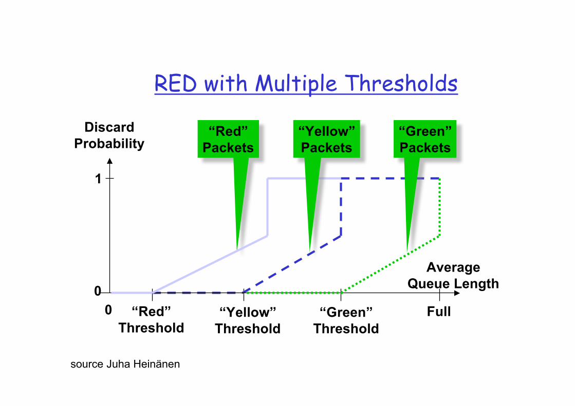
RED with Multiple Thresholds
DiscardProbability
AverageQueue Length0
1
“Red”Threshold
0 “Yellow”Threshold
“Green”Threshold
“Red”Packets
“Green”Packets
“Yellow”Packets
Full
source Juha Heinänen

0 2 4 6 8 10 12 14 16 18 200
0.1
0.2
0.3
0.4
0.5
0.6
0.7
0.8
0.9
1
Link congestion measure
Link marking probability
REM Athuraliya & Low 2000
Main ideas Decouple congestion & performance measure “Price” adjusted to match rate and clear buffer Marking probability exponential in `price’
REM RED
Avg queue
1

Comparison of AQM Performance
DropTailqueue = 94%
REDmin_th = 10 pktsmax_th = 40 pktsmax_p = 0.1
REM
queue = 1.5 pktsutilization = 92%g = 0.05, a = 0.4, f = 1.15

QOS SPECIFICATION,TRAFFIC, SERVICE
CHARACTERIZATION,BASIC MECHANISMS

Service Specification
Loss: probability that a flow’s packet is lost Delay: time it takes a packet’s flow to get from
source to destination Delay jitter: maximum difference between the
delays experienced by two packets of the flow Bandwidth: maximum rate at which the soource
can send traffic QoS spectrum:
Best Effort Leased Line

Hard Real Time: Guaranteed Services
Service contract Network to client: guarantee a deterministic upper
bound on delay for each packet in a session Client to network: the session does not send more than
it specifies
Algorithm support Admission control based on worst-case analysis Per flow classification/scheduling at routers

Soft Real Time: Controlled LoadService
Service contract: Network to client: similar performance as an unloaded
best-effort network Client to network: the session does not send more than
it specifies
Algorithm Support Admission control based on measurement of aggregates Scheduling for aggregate possible

Traffic and Service Characterization
To quantify a service one has two know Flow’s traffic arrival Service provided by the router, i.e., resources reserved
at each router
Examples: Traffic characterization: token bucket Service provided by router: fix rate and fix buffer space
Characterized by a service model (service curveframework)

Ex: Token Bucket
Characterized by three parameters (b, r, R) b – token depth r – average arrival rate R – maximum arrival rate (e.g., R link capacity)
A bit is transmitted only when there is an available token When a bit is transmitted exactly one token is consumed
r tokens per second
b tokens
<= R bpsregulator
time
bits
b*R/(R-r)
slope R
slope r

Token BucketToken Bucket

Token BucketToken Bucket

Traffic Envelope (Arrival Curve)
Maximum amount of service that a flow can sendduring an interval of time t
slope = max average rateb(t) = Envelope
slope = peak rate
t
“Burstiness Constraint”

Arrival curve

Characterizing a Source by TokenBucket
Arrival curve – maximum amount of bitstransmitted by time t
Use token bucket to bound the arrival curve
time
bits
Arrival curve
time
bps

Per-hop Reservation with Token Bucket
Given b,r,R and per-hop delay d Allocate bandwidth ra and buffer space Ba such
that to guarantee d
bits
b
slope rArrival curve
d
Ba
slope ra

What is a Service Model?
The QoS measures (delay,throughput, loss, cost)depend on offered traffic, and possibly otherexternal processes.
A service model attempts to characterize therelationship between offered traffic, deliveredtraffic, and possibly other external processes.
“external process”Network element
offered trafficdelivered traffic
(connection oriented)

Arrival and Departure Process
Network ElementRin Rout
Rin(t) = arrival process = amount of data arriving up to time t
Rout(t) = departure process = amount of data departing up to time t
bits
t
delay
buffer

Delay and Buffer Bounds
t
S (t) = service curve
E(t) = Envelope
Maximum delay
Maximum buffer
bits

SCHEDULING

Packet Scheduling
Decide when and what packet to send on outputlink Usually implemented at output interface
1
2
Scheduler
flow 1
flow 2
flow n
Classifier
Buffermanagement

Mechanisms: Queuing/Scheduling
Use a few bits in header to indicate which queue (class) apacket goes into (also branded as CoS)
High $$ users classified into high priority queues, whichalso may be less populated => lower delay and low likelihood of packet drop
Ideas: priority, round-robin, classification, aggregation, ...
Class C
Class BClass A
Traffic Classes
Traffic Sources
$$$$$$
$$$
$

Scheduling And Policing Mechanisms
Scheduling: choosing the next packet fortransmission on a link can be done following anumber of policies;
FIFO: in order of arrival to the queue; packetsthat arrive to a full buffer are either discarded,or a discard policy is used to determine whichpacket to discard among the arrival and thosealready queued

Priority Queueing Priority Queuing: classes have different priorities; class
may depend on explicit marking or other header info, eg IPsource or destination, TCP Port numbers, etc.
Transmit a packet from the highest priority class with anon-empty queue
Preemptive and non-preemptive versions

Round Robin (RR)
Round Robin: scan class queues serving one from each classthat has a non-empty queue
one round

Weighted Round Robin (WRR)
Assign a weight to each connection and serve aconnection in proportion to its weight
Ex: Connection A, B and C with same packet size and weight
0.5, 0.75 and 1. How many packets from each connectionshould a round-robin server serve in each round?
Answer: Normalize each weight so that they are allintegers: we get 2, 3 and 4. Then in each round ofservice, the server serves 2 packets from A, 3 from Band 4 from C.
one round
w1
w2
wi

(Weighted) Round-Robin Discussion
Advantages: protection among flows Misbehaving flows will not affect the performance of well-
behaving flows Misbehaving flow – a flow that does not implement any congestion
control
FIFO does not have such a property
Disadvantages: More complex than FIFO: per flow queue/state Biased toward large packets (not ATM)– a flow receives
service proportional to the number of packets
If packet size are different, we normalize the weight bythe packet size ex: 50, 500 & 1500 bytes with weight 0.5, 0.75 & 1.0

Generalized Processor Sharing (GPS)
Assume a fluid model of traffic Visit each non-empty queue in turn (like RR) Serve infinitesimal from each Leads to “max-min” fairness
GPS is un-implementable! We cannot serve infinitesimals, only packets
max-min fairness
Soit un ensemble de sources 1,..,n demandant des ressources x1,..,xn avec x1<x2..<xn par exemple. Le serveur a une capacité C.
On donne alors C/n à la source 1. Si C/n>x1, on donne C/n+(C/n-x1)/(n-1) aux (n-1) sourcesrestantes. Si cela est supérieur à x2, on recommence.(Existe en version max-min weighted faire share)

Packet Approximation of Fluid System
GPS un-implementable Standard techniques of approximating fluid GPS
Select packet that finishes first in GPS assuming thatthere are no future arrivals (emulate GPS on the side)
Important properties of GPS Finishing order of packets currently in system
independent of future arrivals
Implementation based on virtual time Assign virtual finish time to each packet upon arrival Packets served in increasing order of virtual times

Fair Queuing (FQ)
Idea: serve packets in the order in which they would havefinished transmission in the fluid flow system
Mapping bit-by-bit schedule onto packet transmissionschedule
Transmit packet with the lowest finish time at any giventime

FQ Simple Example
F=10
Flow 1(arriving)
Flow 2transmitting Output
F=2
F=5
F=8
Flow 1 Flow 2 Output
F=10
Cannot preempt packetcurrently being transmitted

Round Number and Finish Number
Single flow: clock ticks when a bit is transmitted. Forpacket k: Pk = length, Ak = arrival time, Si = begin transmit time, Fk =
finish transmit time Fk = Sk+Pk = max (Fk-1, Ak) + Pk
Multiple flows: clock ticks when a bit from all active flows istransmitted round number Can calculate Fk for each packet if number of flows is known at
all times Fk = current round number + size of packet k, inactive case Fk = largest Fk in the queue + size of packet k, active case
Fi,k,t=max(Fi,k-1,t, Rt)+Pi,k,t
In packet approximation, finish number indicate a relativeorder (service tag) in which a packet is to be served. finish time≠finish number

Example
The round number increases at a rate inversely proportionalto the number of active connections Thus is only used for computing finish numbers
Largest finish number in a connection's queue is theconnection's finish number
Example Suppose packets of size 1, 2 and 2 units arrive at a FQ
scheduler at time for connection A, B and C. Also, assume thata packet of size 2 arrive for connection A at time 4. The linkservice rate is 1 unit/s. Compute the finish number of allpackets.

Illustration
0 2 64 8
roun
d nu
mbe
r
0.5
1.5
2.5
3.5
1
2
3
slope = 1/3
slope = 1/2
slope = 1/3
1 3 5 7

FQ Advantages
FQ protect well-behaved flows from ill-behaved flows Example: 1 UDP (10 Mbps) and 31 TCP’s sharing a 10 Mbps
link
FQ
0
0.2
0.4
0.6
0.8
1
1.2
1.4
1.6
1.8
2
1 4 7 10 13 16 19 22 25 28 31
Flow Number
Th
rou
gh
pu
t(M
bp
s)
RED
0
1
2
3
4
5
6
7
8
9
10
1 4 7 10 13 16 19 22 25 28 31
Flow Number
Th
rou
gh
pu
t(M
bp
s)

Weighted Fair Queueing
Variation of FQ: Weighted Fair Queuing (WFQ) Weighted Fair Queuing: is a generalized Round
Robin in which an attempt is made to provide aclass with a differentiated amount of serviceover a given period of time
Implementing WFQ
WFQ needs per-connection (or per-aggregate)scheduler state→implementation complexity. complex iterated deletion algorithm complex sorting at the output queue on the service tag
WFQ needs to know the weight assigned for eachqueue →manual configuration, signalling.
WFQ is not perfect… Router manufacturers have implemented as early
as 1996 WFQ in their products from CISCO 1600 series Fore System ATM switches

Approximating GPS with WFQ
Fluid GPS system service order
0 2 104 6 8 Weighted Fair Queueing
select the first packet that finishes in GPS

Big Picture FQ does not eliminate congestion it just manages
the congestion You need both end-host congestion control and router
support for congestion control end-host congestion control to adapt router congestion control to protect/isolate
Don’t forget buffer management: you still need todrop in case of congestion. Which packet’s would youdrop in FQ? one possibility: packet from the longest queue

Further readings
See http://www.cnaf.infn.it/~ferrari/ispn.htmlfor Quality of Service list of papers
See http://www.cnaf.infn.it/~ferrari/sched.htmlfor scheduling list of papers

QoS ARCHITECTURES

Stateless vs. Stateful QoS Solutions
Stateless solutions – routers maintain no finegrained state about traffic scalable, robust weak services
Stateful solutions – routers maintain per-flowstate powerful services
guaranteed services + high resource utilizationfine grained differentiationprotection
much less scalable and robust

Integrated Services (IntServ) An architecture for providing QOS guarantees in IP
networks for individual application sessions Relies on resource reservation, and routers need to maintain
state information of allocated resources (eg: g) and respondto new Call setup requests

Integrated Services Model
Flow specification Leacky Bucket, Token Bucket
Routing Admission control Policy control Resource reservation
RSVP
Packet scheduling WFQ, CBQ, RED

Integrated Services: Classes
Guaranteed QOS: this class is provided with firmbounds on queuing delay at a router; envisionedfor hard real-time applications that are highlysensitive to end-to-end delay expectation andvariance
Controlled Load: this class is provided a QOSclosely approximating that provided by anunloaded router; envisioned for today’s IPnetwork real-time applications which perform wellin an unloaded network

Signaling semantics Classic scheme: sender initiated SETUP, SETUP_ACK, SETUP_RESPONSE Admission control Tentative resource reservation and confirmation Simplex and duplex setup; no multicast support

RSVP for the IntServ approach
Resource reSerVation Protocol What is RSVP?
Method for application to specify desired QoS to net Switch state establishment protocol (signaling) Multicast friendly, receiver-oriented Simplex reservations (single direction)
Why run RSVP? Allows precise allocation of network resources Guarantees on quality of service Heterogeneous bandwidth support for multicast Scalable (?)
source Gordon Schaffee
Resource Reservation
Senders advertise using PATH message Receivers reserve using RESV message
Flowspec + filterspec + policy data Travels upstream in reverse direction of Path message
Merging of reservations Sender/receiver notified of changes

RSVP Functional Diagram
Application
RSVPD
AdmissionsControl
PacketClassifier
PacketScheduler
PolicyControlD
ATA
DATA
RSVPD
PolicyControl
AdmissionsControl
PacketClassifier
PacketScheduler
DATA
RoutingProcess
Host Router

SenderReceiver
Stateful Solution: Guaranteed Services
Achieve per-flow bandwidth and delay guarantees Example: guarantee 1MBps and < 100 ms delay to a flow

SenderReceiver
Stateful Solution: Guaranteed Services
Allocate resources - perform per-flow admissioncontrol

SenderReceiver
Stateful Solution: Guaranteed Services
Install per-flow state

SenderReceiver
Stateful Solution: Guaranteed Services
Challenge: maintain per-flow state consistent

SenderReceiver
Stateful Solution: Guaranteed Services
Per-flow classification

SenderReceiver
Stateful Solution: Guaranteed Services
Per-flow buffer management

SenderReceiver
Stateful Solution: Guaranteed Services
Per-flow scheduling

Stateful Solution Complexity
Data path Per-flow classification Per-flow buffer management Per-flow scheduling
Control path install and maintain per-flow state for data and control paths
Classifier
Buffermanagement
Scheduler
flow 1
flow 2
flow n
output interface
…Per-flow State

Stateless vs. Stateful
Stateless solutions are more scalable robust
Stateful solutions provide more powerful and flexibleservices guaranteed services + high resource utilization fine grained differentiation protection

Question
Can we achieve the best of two worlds, i.e., provide servicesimplemented by stateful networks while maintaining advantagesof stateless architectures? Yes, in some interesting cases. DPS, CSFQ.
Can we provide reduced state services, I.e., maintain state onlyfor larger granular flows rather than end-to-end flows? Yes: Diff-serv