quality standards of appliances nepal
TRANSCRIPT

1
Biogas Support Programme
Quality Standards
Biogas Appliances
2058/59 FY
2
Biogas Support Programme
Specifications SANWA BIOGAS VALVE
1. SANWA BIOGAS VALVES shall have a female treading of 16 mm deep on one side of the '/;" ball valve
2. SANWA BIOGAS VALVES shall be fitted on the male side of the W valve with a union nipple
3. The union nipple shall be 40 mm long and fined with a nut to the W ball valve
3.1. The male tread on the union nipple shall be 16 mm long
3.2. The remainder of the union nipple shall have 6 equal sites to allow for fitting with a 18.5 mm spanner
3.3. A rubber ring is fitted between the Vi" bail valve and the union nipple to prevent gas leakage
4. The SANWA BALL VALVES shall be fitted with a butterfly type handle
5. Each SANWA BIOGAS VALVE shall be packed individual in a transparent type of material

3
BSP Standard No.: 750.1
BSP Standard
For
Biogas Stove
Part 1: Construction of Economy Type
Biogas Support Programme PO Box 1966, Kathmandu,
Nepal
4
BSP Standard No.: 750
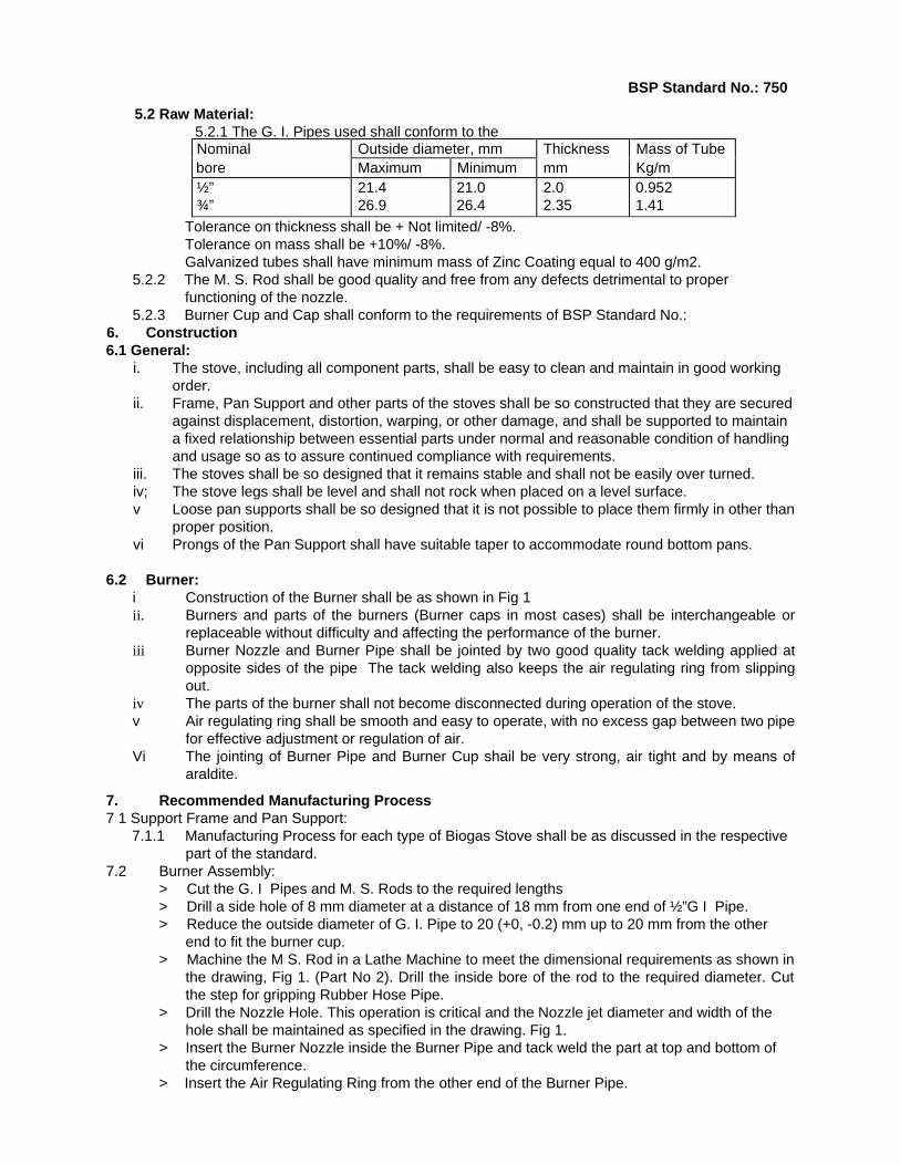
BSP STANDARD FOR BIOGAS STOVE
Part 1: General Requirements
0. Forewords: 0.1 This standard is developed by Biogas Support Programme (BSP), after the draft finalized by a
technical committee representing different stakeholders including BSP, Construction Companies, Appliance Manufacturers, NBSM. etc. Centre for Quality Surveillance Nepal Pvt. Ltd. is involved in the preparation of the draft standard and also provided technical and secretarial support.
0.2 Biogas Support Programme (BSP) is a joint programme of His Majesty's Government of Nepal, the German Financial Co-operation (KfW) and the Netherlands Development Organization (SNV/N) in cooperation with the Agricultural Development Bank of Nepal (ADB/N), Nepal Bank Limited (NBL). Rastriya Banijya Bank (RBB) and recognized Biogas Companies
0.3 Biogas Support Programme (BSP) in a bid to popularize the Biotechnology in Nepal has undertaken several initiatives. Publishing BSP standards on various items relating to construction, production, maintenance of plants and appliances is one of them. These standards are expected to provide sound guideline to the manufacturer in order to produce economic but still acceptable quality of appliances at one end and protect the customer's interest by making them available safe, efficient and economic appliances
0.4 Biogas is obtained by anaerobic fermentation of cattle dung and other similar agricultural organic waste, While it is important to increase the yield of incombustible constituents such as methane and hydrogen inside a Biogas Plant to the maximum possible, it is equally important to achieve safe, efficient and economic utilization of the gas thus obtained.
0.5 This standard has been divided into four parts.
i. First part will cover principle of construction, operation, safety and performance test
requirements of any type of Biogas Stoves
ii Second Part will cover specific requirements of Economy Biogas Stove
iii Third Part will cover specific requirements of Angle Iron Biogas Stove.
iv. Fourth part will cover specific requirements of DELUXE Biogas Stove.
1. Scope
1.1 This standard covers construction, operation, safety requirements and tests for Biogas Stoves intended for use with Biogas.
2. Terminology
Air Regulating Ring - A metal ring provided to cover the air holes at the Burner Pipe near the Burner Nozzle. The Air Regulating Ring controls the flow of air in to the burner pipe and thus controls the gas/ air ratio. By proper adjustment of this ring suitable gas/ air ratio can be obtained for efficient heating.
Burner- A device for the final conveyance of the gas, or a mixture of gas and air to produce a suitable flame.
Burner Clearance - Distance between the burner cap centre and maximum height of the prongs of the pan support. This clearance determines effective distance between the gas flame and the cooking pot.
Burner Cap - Head of the burner, which remains just beyond the outlet end of the mixing chamber and contains a number of ports for gas burning. This can be de-attached for cleaning of the burner assembly.

5
BSP Standard No.: 750
Burner Cup - Mixing chamber of the burner assembly. This is immediately below the burner cap and attached to the burner pipe at the outlet end.
Burner Pipe - Main body of the burner, which holds the gas inlet nozzle at the inlet end and Burner cup on the outlet end. Burner Pipe provides structural support to the Burner Assembly and also provides means for gas conveyance from nozzle to burner port. It also holds air hole for obtaining suitable gas/ air ratio.
Burner Nozzle- An small orifice of pre-determined diameter which allows entry of gas in to the burner
assembly under pressure and high velocity.
Pan Support - The assembly, which is meant to support the vessels. Prongs are parts of pan support.
Prongs - That part of pan support, which actually supports the vessels.
Stove - An assembly of burner/s forming a separate unit allowing direct contact between the flames or hot gases from the burner/s and the vessel above it/ them.
Support Frame - Main structure of the stove including legs. This is the main structure of the stove on which pan support rests.
3. Specification 3.1 Size: Size of the Biogas Stove shall be determined by the size of the pan support. Standard size
of BSP approved stove is 200mm. That is, the size of the pan support shall be 200 X 200 mm.
3.2 Biogas Stoves shall have only one burner 3.3 Burner clearance shall be strictly between 25 to 30 mm to ensure efficient heating performance of
the stove 3.4 The burner shall be in the centre and level position of the Stove assembly.
4. Type
There may be two types of Biogas Stoves depending upon the use of type of Pan Support: 4.1 Fixed Pan Support Type (Type A): In this type of stove the all 4 Prongs are welded directly on the
frame of the stove and can not be de-attached later on. 4.2 Loose Pan Support Type (Type B)- In this type of stove the pan support, normally made of cast
iron including prongs and square, can be de-attached from the frame of the stove.
5. Material
5.1 Part List: Table 1: Part List of the Biogas StovePart No.
Part Name No. of pieces
Material Remarks
A. Burner 1 2 3 4
Burner Pipe Burner Nozzle Air Regulator Ring Cup and Cap
1 1 1 1 pair
Vz" size Light G. I. Pipe, 150 mm long 16 mm dia M. S Rod, 45 mm long ¾" size Light Black Pipe, 18 mm long Aluminum Alloy
G. I. Pipe is preferred.
B Support Frame and Pan Support: Support Frame and Pan Support will be discussed m the respective part of the standard for each type of Biogas stove.
6
BSP Standard No.: 750
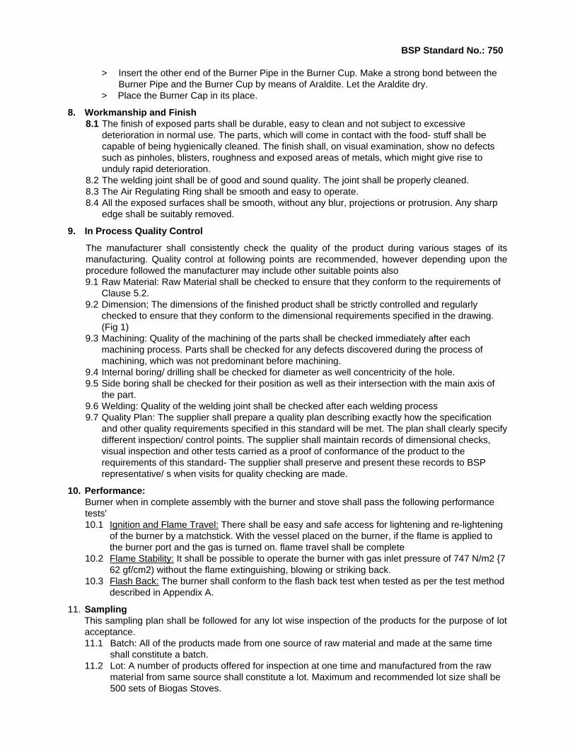
5.2 Raw Material: 5.2.1 The G. I. Pipes used shall conform to the Nominal Outside diameter, mm Thickness Mass of Tube bore Maximum Minimum mm Kg/m ½” ¾”
21.4 26.9
21.0 26.4
2.0 2.35
0.952 1.41
Tolerance on thickness shall be + Not limited/ -8%. Tolerance on mass shall be +10%/ -8%. Galvanized tubes shall have minimum mass of Zinc Coating equal to 400 g/m2.
5.2.2 The M. S. Rod shall be good quality and free from any defects detrimental to proper functioning of the nozzle.
5.2.3 Burner Cup and Cap shall conform to the requirements of BSP Standard No.: 6. Construction 6.1 General:
i. The stove, including all component parts, shall be easy to clean and maintain in good working order.
ii. Frame, Pan Support and other parts of the stoves shall be so constructed that they are secured against displacement, distortion, warping, or other damage, and shall be supported to maintain a fixed relationship between essential parts under normal and reasonable condition of handling and usage so as to assure continued compliance with requirements.
iii. The stoves shall be so designed that it remains stable and shall not be easily over turned. iv; The stove legs shall be level and shall not rock when placed on a level surface. v Loose pan supports shall be so designed that it is not possible to place them firmly in other than
proper position. vi Prongs of the Pan Support shall have suitable taper to accommodate round bottom pans.
6.2 Burner: i Construction of the Burner shall be as shown in Fig 1 ii. Burners and parts of the burners (Burner caps in most cases) shall be interchangeable or
replaceable without difficulty and affecting the performance of the burner. iii Burner Nozzle and Burner Pipe shall be jointed by two good quality tack welding applied at
opposite sides of the pipe The tack welding also keeps the air regulating ring from slipping out.
iv The parts of the burner shall not become disconnected during operation of the stove. v Air regulating ring shall be smooth and easy to operate, with no excess gap between two pipe
for effective adjustment or regulation of air. Vi The jointing of Burner Pipe and Burner Cup shail be very strong, air tight and by means of
araldite.
7. Recommended Manufacturing Process 7 1 Support Frame and Pan Support:
7.1.1 Manufacturing Process for each type of Biogas Stove shall be as discussed in the respective part of the standard.
7.2 Burner Assembly: > Cut the G. I Pipes and M. S. Rods to the required lengths > Drill a side hole of 8 mm diameter at a distance of 18 mm from one end of ½”G I Pipe. > Reduce the outside diameter of G. I. Pipe to 20 (+0, -0.2) mm up to 20 mm from the other
end to fit the burner cup. > Machine the M S. Rod in a Lathe Machine to meet the dimensional requirements as shown in
the drawing, Fig 1. (Part No 2). Drill the inside bore of the rod to the required diameter. Cut the step for gripping Rubber Hose Pipe.
> Drill the Nozzle Hole. This operation is critical and the Nozzle jet diameter and width of the hole shall be maintained as specified in the drawing. Fig 1.
> Insert the Burner Nozzle inside the Burner Pipe and tack weld the part at top and bottom of the circumference.
> Insert the Air Regulating Ring from the other end of the Burner Pipe.
7BSP Standard No.: 750
> Insert the other end of the Burner Pipe in the Burner Cup. Make a strong bond between the
Burner Pipe and the Burner Cup by means of Araldite. Let the Araldite dry. > Place the Burner Cap in its place.
8. Workmanship and Finish 8.1 The finish of exposed parts shall be durable, easy to clean and not subject to excessive
deterioration in normal use. The parts, which will come in contact with the food- stuff shall be capable of being hygienically cleaned. The finish shall, on visual examination, show no defects such as pinholes, blisters, roughness and exposed areas of metals, which might give rise to unduly rapid deterioration.
8.2 The welding joint shall be of good and sound quality. The joint shall be properly cleaned. 8.3 The Air Regulating Ring shall be smooth and easy to operate. 8.4 All the exposed surfaces shall be smooth, without any blur, projections or protrusion. Any sharp
edge shall be suitably removed.
9. In Process Quality Control
The manufacturer shall consistently check the quality of the product during various stages of its manufacturing. Quality control at following points are recommended, however depending upon the procedure followed the manufacturer may include other suitable points also 9.1 Raw Material: Raw Material shall be checked to ensure that they conform to the requirements of
Clause 5.2. 9.2 Dimension; The dimensions of the finished product shall be strictly controlled and regularly
checked to ensure that they conform to the dimensional requirements specified in the drawing. (Fig 1)
9.3 Machining: Quality of the machining of the parts shall be checked immediately after each machining process. Parts shall be checked for any defects discovered during the process of machining, which was not predominant before machining.
9.4 Internal boring/ drilling shall be checked for diameter as well concentricity of the hole. 9.5 Side boring shall be checked for their position as well as their intersection with the main axis of
the part. 9.6 Welding: Quality of the welding joint shall be checked after each welding process 9.7 Quality Plan: The supplier shall prepare a quality plan describing exactly how the specification
and other quality requirements specified in this standard will be met. The plan shall clearly specify different inspection/ control points. The supplier shall maintain records of dimensional checks, visual inspection and other tests carried as a proof of conformance of the product to the requirements of this standard- The supplier shall preserve and present these records to BSP representative/ s when visits for quality checking are made.
10. Performance: Burner when in complete assembly with the burner and stove shall pass the following performance tests' 10.1 Ignition and Flame Travel: There shall be easy and safe access for lightening and re-lightening
of the burner by a matchstick. With the vessel placed on the burner, if the flame is applied to the burner port and the gas is turned on. flame travel shall be complete
10.2 Flame Stability: It shall be possible to operate the burner with gas inlet pressure of 747 N/m2 {7 62 gf/cm2) without the flame extinguishing, blowing or striking back.
10.3 Flash Back: The burner shall conform to the flash back test when tested as per the test method described in Appendix A.
11. Sampling This sampling plan shall be followed for any lot wise inspection of the products for the purpose of lot acceptance. 11.1 Batch: All of the products made from one source of raw material and made at the same time
shall constitute a batch. 11.2 Lot: A number of products offered for inspection at one time and manufactured from the raw
material from same source shall constitute a lot. Maximum and recommended lot size shall be 500 sets of Biogas Stoves.

8
BSP Standard No.: 750 11.3 Defective Sample: Any sample not conforming to any one or more of the specified
requirements. 11.4 Random Sampling: A random sampling method ensuring that every piece of products offered
for inspection shall have equal probability for being selected as a sample shall be followed. Either of the two random sampling method shall be followed: i. Systematic Sampling: ii. Use of Random sampling table:
11.5 Sampling Plan for Visual Inspection and Dimensional Check: i. Sampling Plan
Table 2: Sampling Plan Lot size (a) Sample Size (b) Acceptance No.
(c)Rejection No.
(d)1-15 3 0 116-90 13 1 291-150 20 2 3151-280 32 3 4281-500 50 5 6
ii. Criteria for conformity: For the lot size specified in column (a) of the above table sample size specified in column (b) shall be inspected for visual and dimensional requirements If the number of defected samples is less or equal to the number mentioned in column c then the lot shall be considered conforming to the requirements of this standard in visual and dimensional requirements, if the total number of defective samples is equal to or more than the number mentioned in column d then the lot shall be considered not conforming to the requirements of this standard.
11.6 Sampling Plan for Performance Tests:
1 sample per 100 completed Burner Assembly shall be tested for each of the performance tests specified in Clause 10 of this standard All samples tested shall pass the specified tests for the lot to be accepted.
12. Marking
Every piece of Siogas Stove shall permanently be marked with the following information: 12.1 Manufacturers Name/ or logo/ or any other identification. 12.2 Batch No. 12.3 Approved Colour Code.
13. Packing
Biogas Stoves shall be suitably packed inside a cardboard box to prevent damage during transportation from the manufacturer's workshop to other storage. The cup and burner shall be held together by applying strong binding tape. Similarly the loose frame shall also be held to the body by applying similar strong binding tape. Each packing shall have a label, content of which shall be as shown in Appendix A of this standard.
14. Reference List
14.1 BSP Standard for Burner Cup and Cap.
14.2 IS; 6480- 1971, Indian Standard - Glossary of Terms Relating to Domestic and Commercial Gas- burning Appliances.
14.3 IS. 8749- 1988, Indian Standard - Specification for Biogas Stove
14.4 BSP drawing
14.5 Other BSP Publications.
9
BSP Standard No.: 750
Appendix A
Test Procedure for Flash Back Test:
A vessel having diameter suitable to cover the pan support and filled with water shall be placed on the burner under test. The tap of the burner shall be turned on and gas shall be allowed to flow though the burner at full rate with tap fully opened and gas lighted. After half an hour, the flame shall be immediately reduced to 40% of the rated capacity and brought back to full size. This operation shall be repeated five times. Then the burner shall be put off and immediately re-ignited. This operation shall also be repeated five times. During the test, no flash back shall occur.

10
BSP Standard No.: 750.1
BSP Standard for
Biogas Stove
Part 2: Construction of Economy Type
Biogas Support Programme PO Box 1966, Kathmandu,
Nepal

11
BSP Standard No.: 750.1
BSP Standard for Biogas Stove Part 2: Construction of Economy Type
0. Forewords:
0.1 This standard is developed by Biogas Support Programme (BSP), after the draft finalized by a technical committee representing different stakeholders including BSP, Construction Companies, Appliance Manufacturers, NBSM, etc. Centre for Quality Surveillance Nepal Pvt. Ltd. is involved in the preparation of the draft standard and also provided technical and secretarial support.
0.2 Biogas Support Programme (BSP) is a joint programme of His Majesty's Government of Nepal, the German Financial Co-operation (KfW) and the Netherlands Development Organization (SNV/N) in cooperation with the Agricultural Development Bank of Nepal (ADB/N), Nepal Bank Limited (NBL), Rastriya Banijya Bank (RBB) and recognized Biogas Companies.
0.3 Biogas Support Programme (BSP) in a bid to popularize the Biotechnology in Nepal has undertaken several initiatives Publishing BSP standards on various items relating to construction, production, maintenance of plants and appliances is one of them. These standards are expected to provide sound guideline to the manufacturer in order to produce economic but still acceptable quality of appliances at one end and protect the customer's interest by making them available safe, efficient and economic appliances.
0.4 Biogas is obtained by anaerobic fermentation of cattle dung and other similar agricultural organic waste. While it is important to increase the yield of incombustible constituents such as methane and hydrogen inside a Biogas Plant to the maximum possible, it is equally important to achieve safe, efficient and economic utilization of the gas thus obtained.
0.5 This standard has been divided into four parts: j. First part will cover principle of construction, operation, safety and performance test
requirements of any type of Biogas Stoves. ii. Second Part will cover specific requirements of Economy Biogas Stove iii. Third Part will cover specific requirements of Angle Iron Biogas Stove. iy. Fourth part will cover specific requirements of DELUXE Biogas Stove.
1. Scope
1.1 This standard covers construction of Economy Class of Biogas Stoves intended for use with Biogas
2. Type
Only Fixed Pan Support Type (Type A) of Pan Support shall be available in this class of stoves
3. Construction
3.1 Burner Assembly: Burner Assembly shall conform to the requirements of Part 1 of this standard.
3.2 Support Frame Assembly: Dimensional requirements of the Support Frame Assembly shall be as per the drawing, Fig 1.
12
BSP Standard No.: 750.1
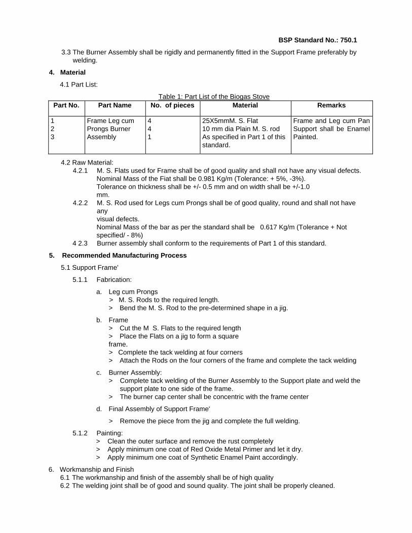
3.3 The Burner Assembly shall be rigidly and permanently fitted in the Support Frame preferably by welding.
4. Material
4.1 Part List:
Table 1: Part List of the Biogas Stove Part No. Part Name No. of pieces Material Remarks
1 2 3
Frame Leg cum Prongs Burner Assembly
4 4 1
25X5mmM. S. Flat 10 mm dia Plain M. S. rod As specified in Part 1 of this standard.
Frame and Leg cum Pan Support shall be Enamel Painted.
4.2 Raw Material: 4.2.1 M. S. Flats used for Frame shall be of good quality and shall not have any visual defects.
Nominal Mass of the Fiat shall be 0.981 Kg/m (Tolerance: + 5%, -3%). Tolerance on thickness shall be +/- 0.5 mm and on width shall be +/-1.0 mm.
4.2.2 M. S. Rod used for Legs cum Prongs shall be of good quality, round and shall not have any visual defects. Nominal Mass of the bar as per the standard shall be 0.617 Kg/m (Tolerance + Not specified/ - 8%)
4 2.3 Burner assembly shall conform to the requirements of Part 1 of this standard.
5. Recommended Manufacturing Process
5.1 Support Frame'
5.1.1 Fabrication:
a. Leg cum Prongs > M. S. Rods to the required length. > Bend the M. S. Rod to the pre-determined shape in a jig.
b. Frame > Cut the M S. Flats to the required length > Place the Flats on a jig to form a square frame. > Complete the tack welding at four corners > Attach the Rods on the four corners of the frame and complete the tack welding
c. Burner Assembly: > Complete tack welding of the Burner Assembly to the Support plate and weld the
support plate to one side of the frame. > The burner cap center shall be concentric with the frame center
d. Final Assembly of Support Frame'
> Remove the piece from the jig and complete the full welding.
5.1.2 Painting: > Clean the outer surface and remove the rust completely > Apply minimum one coat of Red Oxide Metal Primer and let it dry. > Apply minimum one coat of Synthetic Enamel Paint accordingly.
6. Workmanship and Finish 6.1 The workmanship and finish of the assembly shall be of high quality 6.2 The welding joint shall be of good and sound quality. The joint shall be properly cleaned.

13
BSP Standard No.: 750.1
6.3 All the exposed surfaces shall be smooth, without any blur, projections or protrusion. Any sharp edge shall be suitable removed.
7. In Process Quality Control
The manufacturer shall consistently check the quality of the product during various stages of its manufacturing. Quality control at following points are recommended, however depending upon the procedure followed the manufacturer may include other suitable points also: 7.1 Raw Material: Raw Material shall be checked to ensure that they conform to the requirements of
Clause 4.2. 7.2 Dimension: The dimensions of the finished product shall be strictly controlled and regularly
checked to ensure that they conform to the dimensional requirements specified in the drawing. (Fig 1)
7.3 Clearance height between burner and Prong Height shall be checked after the process of welding is completed.
7.4 Centricity of burner cap with respect to frame support shall be checked. 7.5 Welding: Quality of the welding joint shall be checked after each welding process. 7.6 Quality Plan: The supplier shall prepare a quality plan describing exactly how the specification
and other quality requirements specified in this standard will be met. The plan shall clearly specify different inspection/ control points. The supplier shall maintain records of dimensional checks, visual inspection and other tests carried as a proof of conformance of the product to the requirements of this standard. The supplier shall preserve and present these records to BSP representative/ s when visits for quality checking are made.
8. Reference List
8.1 BSP Standard for Burner Cup and Cap.
8.2 IS: 8749- 1988, Indian Standard - Specification for Biogas Stove.
8.3 BSP drawing
8.4 Other BSP Publications.
14
BSP Standard No.: 750.2
BSP Standard for
Biogas Stove
Part 3: Construction of Angle Iron Type
Biogas Support Programme PO Box 1966, Kathmandu,
Nepal
15
BSP Standard No.: 750.2
BSP Standard for Biogas Stove Part 3: Construction of Angle Iron Type
0. Forewords:
0.1 This standard is developed by Biogas Support Programme (BSP), after the draft finalized by a technical committee representing different stakeholders including BSP, Construction Companies, Appliance Manufacturers, NBSM. etc. Centre for Quality Surveillance Nepal Pvt. Ltd. is involved in the preparation of the draft standard and also provided technical and secretarial support.
0.2 Biogas Support Programme (BSP) is a joint programme of His Majesty's Government of Nepal, the German Financial Co-operation (KfW) and the Netherlands Development Organization (SNV/N) in cooperation with the Agricultural Development Bank of Nepal (ADB/N), Nepal Bank Limited (NBL), Rastnya Banijya Bank (RBB) and recognized biogas Companies.
0.3 Biogas Support Programme (BSP) in a bid to popularize the Biotechnology in Nepal has undertaken several initiatives. Publishing BSP standards on various items relating to construction, production, maintenance of plants and appliances is one of them. These standards are expected to provide sound guideline to the manufacturer in order to produce economic but still acceptable quality of appliances at one end and protect the customer's interest by making them available safe, efficient and economic appliances.
0.4 Biogas is obtained by anaerobic fermentation of cattle dung and other similar agricultural organic waste. While it is important to increase the yield of incombustible constituents such as methane and hydrogen inside a Biogas Plant to the maximum possible, it is equally important to achieve safe. efficient and economic utilization of the gas thus obtained.
0.5 This standard has been divided into four parts: i. First part will cover principle of construction, operation, safety and performance test
requirements of any type of Biogas Stoves ii. Second Part will cover specific requirements of Economy Biogas Stove iii. Third Part will cover specific requirements of Angle Iron Biogas Stove. iv. Fourth part will cover specific requirements of DELUXE Biogas Stove.
1. Scope
1.1 This standard covers construction of Angle Iron Class of Biogas Stoves intended for use with Biogas.
2. Type:
8oth types of pan support is available in this class of Biogas Stove:
2.1 Fixed Pan Support Type (Type A): Dimensional requirements of this type of Angle Iron Stove is shown in Fig 1.
2.2 Loose Type Pan Support (Type B): Dimensional requirements of this type of Angle Iron Stove is shown in Fig 2.
16
BSP Standard No.: 750.2
3. Construction 3.1 Burner Assembly: Burner Assembly shall conform to the requirements of Part 1 of this standard. 3.2 Support Frame Assembly: Dimensional requirements of the Support Frame Assembly shall be as
per the drawing, Fig 1 for Type A and Fig 2 for Type B.
'3.3 The Burner Assembly shall be rigidly and permanently fitted in the Support Frame preferably by welding.
4. Material
4.1 Part List:
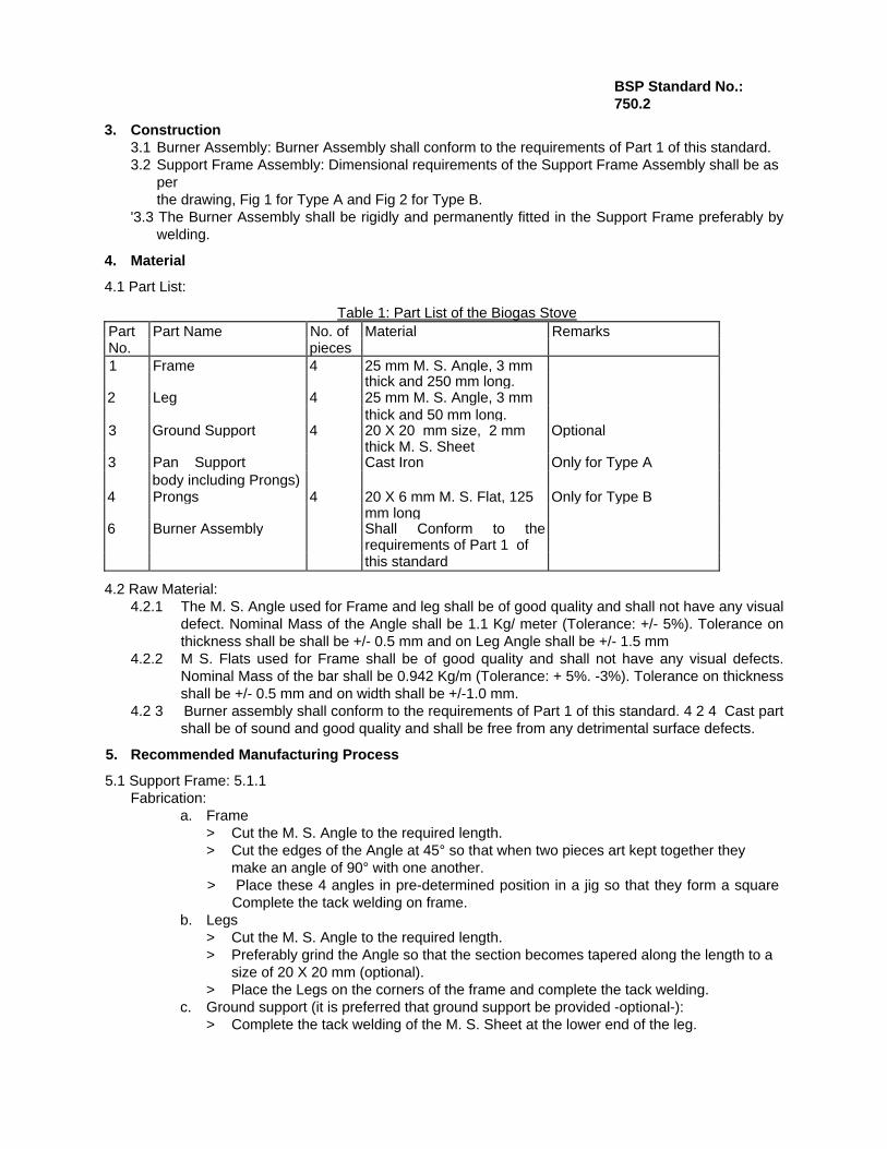
Table 1: Part List of the Biogas Stove Part Part Name No. of Material RemarksNo. pieces 1 Frame 4 25 mm M. S. Angle, 3 mm thick and 250 mm long.2 Leg 4 25 mm M. S. Angle, 3 mm thick and 50 mm long.3 Ground Support 4 20 X 20 mm size, 2 mm Optional thick M. S. Sheet3 Pan Support Cast Iron Only for Type A body including Prongs) 4 Prongs 4 20 X 6 mm M. S. Flat, 125 Only for Type B mm long6 Burner Assembly Shall Conform to the requirements of Part 1 of this standard
4.2 Raw Material: 4.2.1 The M. S. Angle used for Frame and leg shall be of good quality and shall not have any visual
defect. Nominal Mass of the Angle shall be 1.1 Kg/ meter (Tolerance: +/- 5%). Tolerance on thickness shall be shall be +/- 0.5 mm and on Leg Angle shall be +/- 1.5 mm
4.2.2 M S. Flats used for Frame shall be of good quality and shall not have any visual defects. Nominal Mass of the bar shall be 0.942 Kg/m (Tolerance: + 5%. -3%). Tolerance on thickness shall be +/- 0.5 mm and on width shall be +/-1.0 mm.
4.2 3 Burner assembly shall conform to the requirements of Part 1 of this standard. 4 2 4 Cast part shall be of sound and good quality and shall be free from any detrimental surface defects.
5. Recommended Manufacturing Process
5.1 Support Frame: 5.1.1 Fabrication:
a. Frame > Cut the M. S. Angle to the required length. > Cut the edges of the Angle at 45° so that when two pieces art kept together they
make an angle of 90° with one another. > Place these 4 angles in pre-determined position in a jig so that they form a square
Complete the tack welding on frame. b. Legs
> Cut the M. S. Angle to the required length. > Preferably grind the Angle so that the section becomes tapered along the length to a
size of 20 X 20 mm (optional). > Place the Legs on the corners of the frame and complete the tack welding.
c. Ground support (it is preferred that ground support be provided -optional-): > Complete the tack welding of the M. S. Sheet at the lower end of the leg.
17BSP Standard No.: 750.2
d. Prongs (For Type A): > Cut the flat to the required length. Grind it to make taper of 15 mm in one end. > Further grind the edges to the required radius. > Complete tack welding of the Prongs on four corners of the frame.
e. Burner Assembly: > Complete tack welding of the Burner Assembly to the Support plate and weld the
support plate to one side of the frame. > The burner cap center shall be concentric with the frame center.
f. Full Assembly: > Remove the assembly from the jig and complete the full welding.
5.1.2 Painting: > Clean the outer surface and remove the rust completely > Apply minimum one coat of Red Oxide Metal Primer and let it dry. > Apply minimum one coat of Synthetic Enamel Paint accordingly.
6. Workmanship and Finish 6.1 The workmanship and finish of the assembly shall be of high quality. 6.2 The welding joint shall be of good and sound quality. The joint shall be properly cleaned. 6.3 All the exposed surfaces shall be smooth, without any blur, projections or protrusion. Any sharp
edge shall be suitable removed.
7. In Process Quality Control The manufacturer shall consistently check the quality of the product during various stages of its manufacturing. Quality control at following points are recommended, however depending upon the procedure followed the manufacturer may include other suitable points also 7.1 Raw Material: Raw Material shall be checked to ensure that they conform to the requirements of
Clause 4.2. 7.2 Dimension: The dimensions of the finished product shall be strictly controlled and regularly
checked to ensure that they conform to the dimensional requirements specified in the drawing. (Fig 1)
7.3 Clearance height between burner and pan support (or. prong height) shall be checked after the process of welding is complete.
7.4 Centricity of burner cap with respect to frame support shall be checked. 7.5 Welding: Quality of the welding joint shall be checked after each welding process 7.6 Visual inspection of the Enamel paint shall be earned out when the surface is dry. 7.7 Quality Plan- The supplier shall prepare a quality plan describing exactly how the specification
and other quality requirements specified in this standard will be met. The plan shall clearly specify different inspection/ control points. The supplier shall maintain records of dimensional checks, visual inspection and other tests carried as a proof of conformance of the product to the requirements of this standard. The supplier shall preserve and present these records to BSP representative/ s when visits for quality checking are made.
8. Reference List
8.1 BSP Standard for Burner Cup and Cap
8.2 IS: 8749- 1988, Indian Standard - Specification for Biogas Stove
8.3 BSP drawing
8.4 Other BSP Publications.
18
BSP Standard No.: 750.3
BSP Standard
for
Biogas Stove
Part 4: Construction of Deluxe Type
Biogas Support Programme
PO Box 1966, Kathmandu,
Nepal
19
BSP Standard No.: 750.3
BSP Standard for Biogas Stove Part 4: Construction of Deluxe Type
0. Forewords: 0.1 This standard is developed by Biogas Support Programme (BSP), after the draft finalized by a
technical committee representing different stakeholders including BSP. Construction Companies, Appliance Manufacturers, NBSM, etc. Centre for Quality Surveillance Nepal Pvt. Ltd. is involved in the preparation of the draft standard and also provided technical and secretarial support.
0.2 Biogas Support Programme (BSP) is a joint programme of His Majesty's Government of Nepal, the German Financial Co-operation (KfW) and the Netherlands Development Organization (SNV/N) in cooperation with the Agricultural Development Bank of Nepal (ADB/N), Nepal Bank Limited (NBL), Rastrlya Banijya Bank (R8B) and recognized Biogas Companies.
0.3 Biogas Support Programme (BSP) in a bid to popularize the Biotechnology in Nepal has undertaken several initiatives. Publishing BSP standards on various items relating to construction, production, maintenance of plants and appliances is one of them. These standards are expected to provide sound guideline to the manufacturer in order to produce economic but still acceptable quality of appliances at one end and protect the customer's interest by making them available safe, efficient and economic appliances.
0.4 Biogas is obtained by anaerobic fermentation of cattle dung and other similar agricultural organic waste. While it is important to increase the yield of incombustible constituents such as methane and hydrogen inside a Biogas Plant to the maximum possible, it is equally important to achieve safe, efficient and economic utilization of the gas thus obtained.
0.5 This standard has been divided into four parts: i. First part will cover principle of construction, operation, safety and performance test
requirements of any type of 8iogas Stoves. ii. Second Part will cover specific requirements of Economy Biogas Stove iii. Third Part will cover specific requirements of Angle Iron Biogas Stove. iv; Fourth part will cover specific requirements of DELUXE Biogas Stove.
1. Scope
1.1 This standard covers construction of Deluxe Class of Biogas Stoves intended for use with Biogas.
2. Type
2.1 For Deluxe Class of Biogas Stoves, only type B, that is loose pan support type, is applicable.
3. Construction 3.1 Burner Assembly: Burner Assembly shall conform to the requirements of Part 1 of this standard. 3.2 Support Frame Assembly: Dimensional requirements of the Support Frame Assembly shall be as
per the drawing, Fig 1.
3.3 The Burner Assembly shall be rigidly and permanently fitted in the Support Frame preferably by welding.

20
BSP Standard No.: 750.3
4. Material
4.1 Part List:
Table 1: Part List of the Biogas Stove Part Part Name No. of Material RemarksNo, pieces 1 Base Frame 1 Aluminum Casting The stove after assembly shall be2 Pan Support 1 Cast Iron painted by Enamel Paint. 3 Burner Assembly 1 Shall Conform to the requirements of Part 1 of this standard.4 Burner Support 1 M. S. Sheet.
5 Nut and bolt 2 M. S. Steel
4.2 Raw Material: 4.2.1 The Frame shall be made of Aluminum casting. The casting shall be free from any
casting defects such as blow holes, gas cavities, and other defects detrimental to the functioning of the stove.
4.2.2 The Pan Support shall be made of Cast Iron. The casting shall be free from any casting defects such as blow holes, gas cavities and other defects detrimental to the functioning of the stove.
4.2.3 Burner assembly shall conform to the requirements of Part 1 of this standard 4.2.4 M S. Sheet and Nut and bolt shall be standard quality and shall be free from any visual
defects detrimental to the functioning of the stove.
5. Recommended Manufacturing Process
5.1 Support Frame: 5.1.1 Burner Support:
> Drill a hole in the centre of the sheet. Diameter of the hole shall be such that the burner pipe should just enter the hole.
> Drill two holes on either side of the central hole. > Insert the Burner Assembly inside the Burner support hole and weld it in the
appropriate place. Complete the full welding.
5.1.2 Final Assembly > Assemble the Burner Assembly in a pre-cast hole on the Base Frame and tighten it
into position by means of two sets of Nut and Bolt. > Place the Pan Support over the Base Frame to complete the assembly,
5.1.3 Painting: > Clean the outer surface of the frame and smoothen the surface > Apply minimum one coat of Red Oxide Metal Primer and let it dry. > Apply minimum one coat of Synthetic Enamel Paint accordingly.
6. Workmanship and Finish 6.1 The workmanship and finish of each cast part shall be of sound and high quality. Castings shall
be free from any visual defects. 6.2 The welding joint shall be of good and sound quality. The joint shall be properly cleaned. 6.3 All the exposed surfaces shall be smooth, without any blur, projections or protrusion. Any sharp
edge shall be suitable removed.
7. In Process Quality Control The manufacturer shall consistently check the quality of the product during various stages of its manufacturing. Quality control at following points are recommended, however depending upon the

21procedure followed the manufacturer may include other suitable points also;
22BSP Standard No.: 750.3
7.1 Raw Material: Raw Material shall be checked to ensure that they conform to the requirements of
Clause 4.2. 7.2 Dimension; The dimensions of the finished product shall be strictly controlled and regularly checked to
ensure that they conform to the dimensional requirements specified in the drawing, (Fig 1). Dimension control of the interface between the Pan Support and Base Frame is very critical as the parts shall be interchangeable.
7.3 Clearance height between burner and pan support shall be checked after the process of welding is complete.
7.4 Centricity of burner cap with respect to frame support shall be checked. 7.5 Welding: Quality of the welding joint shall be checked after each welding process. 7.6 Visual inspection of the Enamel paint shall be earned out when the surface is dry. 7.7 Quality Plan: The supplier shall prepare a quality plan describing exactly how the specification and
other quality requirements specified in this standard will be met. The plan shall clearly specify different inspection/ control points. The supplier shall maintain records of dimensional checks, visual inspection and other tests carried as a proof of conformance of the product to the requirements of this standard. The supplier shall preserve and present these records to BSP representative/ s when visits for quality checking are made.
8. Reference List
8.1 BSP Standard for Burner Cup and Cap.
8.2 IS: 8749- 1988. Indian Standard - Specification for Biogas Stove.
8.3 BSP drawing
8.4 Other BSP Publications.
23
BSP Standard No.: 751
BSP Standard for
Biogas Tap
(With Varying Knob)
Biogas Support Programme PO Box 1966, Kathmandu,
Nepal

24
BSP Standard No.: 751
BSP STANDARD FOR BIOGAS TAP (WITH VARYI NG KNOB)
0. Forewords 0.1 This standard is developed by Biogas Support Programme (BSP), after the draft finalized by a
technical committee representing different stakeholders including BSP, Construction Companies, Appliance Manufacturers, NBSM, etc. Centre for Quality Surveillance Nepal Pvt. Ltd. is involved in the preparation of the draft standard and also provided technical and secretarial support.
0.2 Biogas Support Programme (BSP) is a joint programme of His Majesty's Government of Nepal, the German Financial Co-operation (KfW) and the Netherlands Development Organization (SNV/N) in cooperation with the Agricultural Development Bank of Nepal (ADB/N), Nepal Bank Limited (NBL), Rastriya Banijya Bank (RBB) and recognized Biogas Companies.
0.3 Biogas Support Programme (BSP) in a bid to popularize the Biotechnology in Nepal has undertaken several initiatives. Publishing BSP standards on various items relating to construction, production, maintenance of plants and appliances is one of them. These standards are expected to provide sound guideline to the manufacturer in order to produce economic but still acceptable quality of appliances at one end and protect the customer's interest by making them available safe, efficient and economic appliances.
0.4 Biogas is obtained by anaerobic fermentation of cattle dung and other similar agricultural organic waste. While it is important to increase the yield of incombustible constituents such as methane and hydrogen inside a Biogas Plant to the maximum possible, it is equally important to achieve safe. efficient and economic utilization of the gas thus obtained.
1. Scope
1.1 This standard covers construction, operation, and tests for Biogas Gas Tap intended for use in operating Biogas lines to regulate the gas supply to the Bio Gas Stove.
2. Terminology
Gas Tap - A device used to regulate the flow of gas. This device is attached at the end of gas line and just before the gas stove/ or lamp.
3. Specification 3.1 The Gas Tap shall conform to the dimensional requirements as per the supplied drawing {Fig. 1). 3.2 The tap shall be so designed that it allows for different flow rate of gas at different knob positions. 3.3 It shall be possible to close the tap completely at one knob position
4. Material
4.1 Part List:
Table 1: Part List Part No. Part Name Description Remarks1 Cylinder Cast or drawn Brass Rod2 Pipe Vi" G. I. Pipe x 80 mm3 Piston Cast or drawn Brass Rod4 Retainer Cast or drawn Brass Rod5 Handle or Knob Suitable material6 Washer MS Plate, 2.0 mm thick 7 O-Ring Rubber

25
BSP Standard No.: 751
The manufacturer may combine retainer and knob in one part. The recommended material may be Aluminum Alloy.
4.2 Raw Maerial:
4.2.1 The G. I. Pipe used shall conform to the requirements of Light Grade Pipe of NS: 199, Nepal Standard for Galvanized M. S. Pipe for Water Supply: Some specific features of the pipe shall be as follows: i. Mass: 0.952 Kg/m (Tolerance: +10% to-8%) ii. Thickness: 2.0 mm (Tolerance: + Not limited, - 8%) iii. Outside diameter: In between 21.0 and 21.4 mm iv. Zinc Coating: 400 gm/ m2 v. The thread mating with the reducer shall be taper thread conforming to the
requirements of IS: 554: 1985, Indian Standard for Dimension for Pipe thread where pressure tight joints are made on threads.
4.2.2 Brass Parts: Recommended material used to manufacture the Brass parts of Biogas Tap shall conform to the requirements of Designation LCB2 of IS: 292- 1983, Specification of Leaded Brass Ingots and Castings. Any other suitable brass material also may be used for the purpose. Some properties of recommended material and another suitable material (as an example) is given in following table: s. Characteristics LCB2oflS292 Alternate N only) 1 Chemical Composition i. Copper plus incidental Nickel 63.0 to 70.0% 59.0 to 62.0% ii. Lead 1.0 to 1.3% 0.5 to 1,0% iii. Tin 1.50% Max. 0.5 to 1,0% iv. Iron 0.75%, Max. 0.1% Max. v. Aluminum 0.01%, Max. ... vi. Other impurities 0.2% Max. vii Zinc Remainder Remainder2 Physical Properties i. Tensile Strength 345 N/ mm2 ii. %Elongation 20%. Min
Castings and brass rod shall be free from any viual defects and shall be sound, free from laps, blow-holes and pitting, and the surface shall be clean and smooth.
4 2.3 M S Steel, Rubber O-Ring. and other material to be used also shall be of good quality and free from any defects detrimental to their functioning.
5. Recommended Manufacturing Process 5.1 Cut the different parts, for example G.I. Pipe and Brass Parts to the required length. 5.2 Cold stamp the washer from the M. S. Sheet in a Press. 5.3 Weld the washer closing one end of the Pipe. 5.4 Cut the external taper thread at one end of G. I. Pipe. 5.5 Drill the 12 mm Side hole at the position given in the drawing, Fig. 1. 5.6 Machine the brass parts in a lathe machine. Carry out various operations like boring, drilling,
rimming, grooving, step cutting, side drilling, internal and external threading as appropriate to meet the dimensional requirements of the drawing, Fig. 1.
5.7 Fit the Cylinder to the Side hole drilled in the pipe 5.8 Join the mating point of the G. I. Pipe and Cylinder by Pb Sn Soldering. 5.9 Assemble the parts.
26
BSP Standard No.: 751
6. Workmanship and Finish 6.1 The Gas Tap shall be made from good quality G. I. Pipe and brass rods. The brass rod shall be
free from any casting defects detrimental to the functioning of the Gas Tap.
6.2 The welding and soldering joint shall be of good and sound quality. The joint shall be properly cleaned.
6.3 The threading shall be well cut, clean and correct. 6.4 The surface of the Gas Tap shall be smooth, without any blur, projections or protrusion. Any
sharp edge shall be suitable removed.
7. In Process Quality Control
The manufacturer shall consistently check the quality of the product during various stages of its manufacturing. Quality control at following points are recommended, however depending upon the procedure followed the manufacturer may include other suitable points also: 7.1 Raw Material: The supplier shall check the quality of raw material, for example: The G. I. Pipe. Brass
rods, and other material to ensure that they meet the requirements stipulated in clause 4.2. 7.2 Dimension: The dimensions of the finished product shall be strictly controlled and regularly
checked to ensure that they conform to the dimensional requirements specified in the drawing. (Fig 1)
7.3 Machining: Quality of the machining of the parts shall be checked immediately after each machining process. Parts shaft be checked for any casting defects discovered during the process of machining, which was not predominant before machining.
7.4 Internal boring/ drilling shall be checked for diameter as well concentricity of the hole. 7.5 Side boring shall be checked for their position as well as their intersection with the main axis of
the part.
7.6 External Threading in the G I. Pipe & Cylinder and Internal threading in the Retainer shall be checked to ensure good quality threading.
7.7 Welding and Soldering: Quality of the welding and soldering joint between the two parts shall be checked after each operation.
7 8 Quality Plan: The supplier shall prepare a quality plan describing exactly how the specification and
other quality requirements specified in this standard will be met The supplier shall maintain records of dimensional checks, visual inspection and other tests carried as a proof of conformance of the product to the requirements of this standard. The supplier shall preserve and present these records to BSP representative/ s when visits for quality checking are made,
8. Performance
8.1 The Gas Tap after complete assembly shall pass the pressure test specified in Annex A of this standard.
8 2 The supplier shall test 100% of the Gas Taps to the pressure test
9. Sampling This sampling plan shall be followed for any lot wise inspection of the products for the purpose of lot acceptance. 9.1 Batch: All of the products made from one source of raw material purchased at one time shall
constitute a batch. 9.2 Lot: A number of products offered for inspection at one time and manufactured from the raw
material from same source shall constitute a lot. Maximum and recommended lot size shall be 500 units of Gas Tap.
9.3 Defective Sample: Any sample not conforming to any one or more of the specified requirements.

27BSP Standard No.: 751
9.4 Random Sampling: A random sampling method ensuring that every pieces of products offered for
inspection shall have equal probability for being selected as a sample shall be followed. Either of the two random sampling method shall be followed: i Systematic Sampling: 11. Use of Random sampling table
9.5 Sampling Plan for Visual Inspection and Dimensional Check:
I Sampling Plan
Table 2: Sampling Plan Lot size
(a) Sample Size
(b)Acceptance No. (c) Rejection No.
(d)1-15 3 0 116-90 13 1 291-150 20 2 3151-280 32 3 4281-500 50 5 6
Ii Criteria for conformity: For the lot size specified in column (a) of the above table sample size
specified in column (b) shall be inspected for visual and dimensional requirements. If the number of defected samples is less or equal to the number mentioned in column c then the lot shall be considered conforming to the requirements of this standard in visual and dimensional requirements, if the total number of defective samples is equal to or more than the number mentioned in column d then the lot shall be considered not conforming to the requirements of this standard.
9.6 Sampling Plan for Performance Tests:
1 sample per 100 pieces of Gas Tap offered for inspection shall be tested for the performance test specified in Clause 8.1 of this standard. All the tested samples shall pass the specified tests for the lot to be accepted.
10. Marking
10.1 Every piece of Gas Tap shall permanently be marked on outer surface of the pipe with the following information: i. Manufacturers Name/ or logo/ or any other identification. ii. Batch No. iii. Approved colour marking.
10.2 Individual packing of Biogas tap shall be provided with a printed label with details exactly as shown in Appendix B of this standard.
11. Packing
11.1 One Gas tap, two O- rings, and some lubricating grease shall be suitably packed in a BSP approved transparent packing material A number of such gas Taps shall be packed inside strong suitable cardboard box.
12. Reference List 12.1 NS. 199 Nepal Standard - Galvanized M. S. Pipe for Water Supply. 12.2 IS: 292, Indian Standard - Specification for Leaded Brass Ingots and Castings 12.3 IS: 554, Indian Standard - Dimensions for Pipe Threads where Pressure-Tight Joints are
Made on Threads. 12.4 IS. 4736, Indian Standard - Hot Dip Zinc Coatings on Mild Steel Tubes. 12.5 BSP drawing. 12.6 Other BSP Publications.

28
BSP Standard No.: 751
Appendix A
PROCEDURE PRESSURE TEST: The Piston of the test piece shall be closed air-tight. The open end of the G. I. Pipe shall be connected to a device (for example air compressor) for applying an air pressure. The sample then shall be applied to a minimum internal air pressure of 0.5 Kg/ cm2 {49 x 103 N/m2). The test piece shall not show any sign of air leakage from any part, surface or mating surfaces during the test.
The air leakage can be tested by any suitable means such as by immersing the sample completely inside a water bath or by applying soap/ shampoo solution.
29
BSP Standard No.: 752
BSP Standard for
Biogas Water Drain
Biogas Support Programme
PO Box 1966, Kathmandu,
Nepal

30
BSP Standard No.: 752
BSP STANDARD FOR BIOGAS WATER DRAIN
0. Forewords:
0.1 This standard is developed by Biogas Support Programme (BSP), after the draft finalized by a technical committee representing different stakeholders including BSP, Construction Companies, Appliance Manufacturers, NBSM, etc. Centre for Quality Surveillance Nepal Pvt. Ltd. is involved in the preparation of the draft standard and also provided technical and secretarial support.
0.2 Biogas Support Programme (BSP) is a joint programme of His Majesty's Government of Nepal, the German Financial Co-operation (KfW) and the Netherlands Development Organization (SNV/N) in cooperation with the Agricultural Development Bank of Nepal (ADB/N), Nepal Bank Limited (NBL), Rastriya Banijya Bank (RBB) and recognized Biogas Companies.
0.3 Biogas Support Programme {BSP) in a bid to popularize the Biotechnology in Nepal has undertaken several initiatives, Publishing BSP standards on various items relating to construction, production, maintenance of plants and appliances is one of them. These standards are expected to provide sound guideline to the manufacturer in order to produce economic but still acceptable quality of appliances at one end and protect the customer's interest by making them available safe, efficient and economic appliances.
0.4 Biogas is obtained by anaerobic fermentation of cattle dung and other similar agricultural organic waste. While it is important to increase the yield of incombustible constituents such as methane and hydrogen inside a Biogas Plant to the maximum possible, it is equally important to achieve safe, efficient and economic utilization of the gas thus obtained.
1. Scope
1.1 This standard covers construction, operation, and tests for Biogas Water Drain intended for use in operating Biogas pipeline to enable to drain the condensed water in the supply line
2. Terminology
Water Drain -A device used to remove water precipitated from gas at the gas pipeline.
3. Specification
3 1 The Water Dram shall conform to the dimensional requirements as per the supplied drawing (Fig1)
3.2 The Water Drain shall be easy to operate.
4. Material
4.1 Part List:
Table 1: Part List Part No. Part Name Description Remarks 1 2 3 4 5
Pipe Water Release Screw Nut Handle or Knob Washer
½ G I. Pipe x 150 mm Cast or drawn Brass Rod Cast or drawn Brass Rod Cast/ Drawn Wires, etc. Nylon
4.2 Raw Material:
4.2.1 The G. I. Pipe used shall conform to the requirements of Light Grade Pipe of NS: 199. Nepal Standard for Galvanized M. S. Pipe for Water Supply.
31
BSP Standard No.: 752
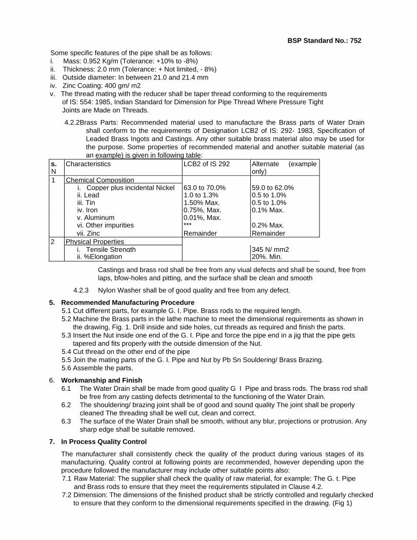
Some specific features of the pipe shall be as follows: i. Mass: 0.952 Kg/m (Tolerance: +10% to -8%) ii. Thickness: 2.0 mm (Tolerance: + Not limited, - 8%) iii. Outside diameter: In between 21.0 and 21.4 mm iv. Zinc Coating: 400 gm/ m2 v. The thread mating with the reducer shall be taper thread conforming to the requirements
of IS: 554: 1985, Indian Standard for Dimension for Pipe Thread Where Pressure Tight Joints are Made on Threads.
4.2.2Brass Parts: Recommended material used to manufacture the Brass parts of Water Drain shall conform to the requirements of Designation LCB2 of IS: 292- 1983, Specification of Leaded Brass Ingots and Castings. Any other suitable brass material also may be used for the purpose. Some properties of recommended material and another suitable material (as an example) is given in following table:
s. Characteristics LCB2 of IS 292 Alternate (example N only) 1 Chemical Composition i. Copper plus incidental Nickel 63.0 to 70.0% 59.0 to 62.0% ii. Lead 1.0 to 1.3% 0.5 to 1.0% iii. Tin 1.50% Max. 0.5 to 1.0% iv. Iron 0.75%, Max. 0.1% Max. v. Aluminum 0.01%, Max. vi. Other impurities *** 0.2% Max. vii. Zinc Remainder Remainder2 Physical Properties i. Tensile Strength 345 N/ mm2 ii. %Elongation 20%. Min.
Castings and brass rod shall be free from any viual defects and shall be sound, free from laps, bfow-holes and pitting, and the surface shall be clean and smooth
4.2.3 Nylon Washer shall be of good quality and free from any defect.
5. Recommended Manufacturing Procedure 5.1 Cut different parts, for example G. I. Pipe. Brass rods to the required length. 5.2 Machine the Brass parts in the lathe machine to meet the dimensional requirements as shown in
the drawing, Fig. 1. Drill inside and side holes, cut threads as required and finish the parts. 5.3 Insert the Nut inside one end of the G. I. Pipe and force the pipe end in a jig that the pipe gets
tapered and fits properly with the outside dimension of the Nut. 5.4 Cut thread on the other end of the pipe 5.5 Join the mating parts of the G. I. Pipe and Nut by Pb Sn Souldering/ Brass Brazing. 5.6 Assemble the parts.
6. Workmanship and Finish 6.1 The Water Drain shall be made from good quality G I Pipe and brass rods. The brass rod shall
be free from any casting defects detrimental to the functioning of the Water Drain. 6.2 The shouldering/ brazing joint shall be of good and sound quality The joint shall be properly
cleaned The threading shall be well cut, clean and correct. 6.3 The surface of the Water Drain shall be smooth, without any blur, projections or protrusion. Any
sharp edge shall be suitable removed.
7. In Process Quality Control
The manufacturer shall consistently check the quality of the product during various stages of its manufacturing. Quality control at following points are recommended, however depending upon the procedure followed the manufacturer may include other suitable points also: 7.1 Raw Material: The supplier shall check the quality of raw material, for example: The G. t. Pipe
and Brass rods to ensure that they meet the requirements stipulated in Clause 4.2. 7.2 Dimension: The dimensions of the finished product shall be strictly controlled and regularly checked
to ensure that they conform to the dimensional requirements specified in the drawing. (Fig 1)

32BSP Standard No.: 752
7.3 Machining: Quality of the machining of the parts shall be checked immediately after each
machining process. Parts shall be checked for any casting defects discovered during the process of machining, which was not predominant before machining.
7.4 Internal boring/ drilling shall be checked for diameter as well concentricity of the hole. 7.5 Side boring shall be checked for their position as well as their intersection with the main axis of
the part. 7.6 External Threading in the G. I. Pipe & Water Release Screw and Internal threading in the Nut
shall be checked to ensure good quality threading. 7.7 Soldering/ Brazing Joint: Quality of the soldering joint between the two parts shall be checked
after the process of soldering is completed. 7.8 Quality Plan: The supplier shall prepare a quality plan describing exactly how the specification
and other quality requirements specified in this standard will be met. The supplier shall maintain records of dimensional checks, visual inspection and other tests carried as a proof of conformance of the product to the requirements of this standard. The supplier shall preserve and present these records to BSP representative/ s when visits for quality checking are made.
8. Performance 8.1 The Water Drain after complete assembly shall pass the pressure test specified in Annex A of the
standard. 8.2 The supplier shall test 100% of the product to the pressure test.
9. Sampling This sampling plan shall be followed for any lot wise inspection of the products for the purpose of lot acceptance. 9.1 Batch: All of the products made from one source of raw material purchased at one time shall
constitute a batch. 9.2 Lot: A number of products offered for inspection at one time and manufactured from the raw
material from same source shall constitute a lot Maximum and recommended lot size shall be 500 units of Water Drain.
9.3 Defective Sample: Any sample not conforming to any one or more of the specified requirements 9.4 Random Sampling: A random sampling method ensuring that every piece of products offered for
inspection shall have equal probability for being selected as a sample shall be followed. Either of the two random sampling method shall be followed: I Systematic Sampling: ii. Use of Random sampling table:
9.5 Sampling Plan for Visual Inspection and Dimensional Check: i. Sampling Plan
Table 2: Sampling Plan Lot size
(a) Sample Size (b) Acceptance No. (c) Rejection No. (d)
1-15 0 116-90 13 1 291-150 20 2 3151-280 32 3 4281-500 50 5 6
ii. Criteria for conformity: For the lot size specified in column (a) of the above table sample size
specified in column (b) shall be inspected for visual and dimensional requirements If the number of defective samples is less or equal to the number mentioned in column c then the lot shall be considered conforming to the requirements of this standard in visual and dimensional requirements, if the total number of defective samples is equal to or more than the number mentioned in column d then the lot shall be considered not conforming to the requirements of this standard

33
BSP Standard No.: 752.
9.6 Sampling Plan for Performance Tests:
1 sample per 100 pieces of Water Drain offered for inspection shall be tested for the performance test specified in Clause 8.1 of this standard. All the tested samples shall pass the specified tests for the lotto be accepted.
10. Marking
10.1 Every piece of Water Drain shall permanently be marked on the outer surface of the pipe with the following information:
i, Manufacturers Name/ or logo/ or any other identification.
ii. Batch No.
iii. Approved colour code.
10.2 Individual packing of Water drain shall be provided with a printed label with details exactly as shown in Appendix B of this standard.
11. Packing
One Water drain and one spare washer shall be packed in a BSP approved transparent material. A number of such water drains shall be suitably packed in a strong and suitable cardboard box.
12. Reference List
12.1 NS: 199 Nepal Standard - Galvanized M. S. Pipe for Water Supply.
12.2 IS: 292. Indian Standard - Specification for Leaded Brass Ingots and Castings.
12.3 IS: 554, Indian Standard - Dimensions for Pipe Threads where Pressure-Tight Joints are Made on Threads.
12.4 IS: 4736, Indian Standard - Hot Dip Zinc Coatings on Mild Steel Tubes.
12.5 BSP drawing.
12.6 Other BSP Publications.
34
BSP Standard No.: 752
Appendix A
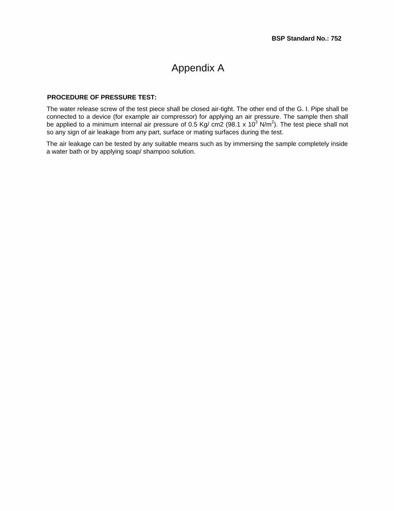
PROCEDURE OF PRESSURE TEST:
The water release screw of the test piece shall be closed air-tight. The other end of the G. I. Pipe shall be connected to a device (for example air compressor) for applying an air pressure. The sample then shall be applied to a minimum internal air pressure of 0.5 Kg/ cm2 (98.1 x 10³ N/m2). The test piece shall not so any sign of air leakage from any part, surface or mating surfaces during the test.
The air leakage can be tested by any suitable means such as by immersing the sample completely inside a water bath or by applying soap/ shampoo solution.

35
BSP Standard No.: 755
BSP Standard
for
Burner Cup and Cap
to be used in Biogas Stoves
Biogas Support Programme PO Box 1966, Kathmandu,
Nepal
36
BSP Standard No.: 755
BSP Standard for Burner Cup & Cap
0. Forewords: 0.1 This standard is developed by Biogas Support Programme (BSP). after the draft finalized by a
technical committee representing different stakeholders including BSP, Construction Companies, Appliance Manufacturers, NBSM, etc. Centre for Quality Surveillance Nepal Pvt. Ltd. is involved in the preparation of the draft standard and also provided technical and secretarial support.
0.2 Biogas Support Programme (BSP} is a joint programme of His Majesty's Government of Nepal, the
German Financial Co-operation (KfW) and the Netherlands Development Organization (SNV/N) in cooperation with the Agricultural Development Bank of Nepal (ADB/N), Nepal Bank Limited (NBL), Rastriya Banijya Bank (RBB) and recognized Biogas Companies.
0.3 Biogas Support Programme (BSP) in a bid to popularize the Biotechnology in Nepal has undertaken several initiatives. Publishing BSP standards on various items relating to construction, production, maintenance of plants and appliances is one of them. These standards are expected to provide sound guideline to the manufacturer in order to produce economic but still acceptable quality of appliances at one end and protect the customer's interest by making them available safe, efficient and economic appliances.
0,4 Biogas is obtained by anaerobic fermentation of cattle dung and other similar agricultural organic waste. While it is important to increase the yield of incombustible constituents such as methane and hydrogen inside a Biogas Plant to the maximum possible, it is equally important to achieve safe, efficient and economic utilization of the gas thus obtained.
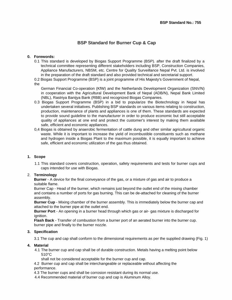
1. Scope
1.1 This standard covers construction, operation, safety requirements and tests for burner cups and caps intended for use with Biogas.
2. Terminology Burner - A device for the final conveyance of the gas, or a mixture of gas and air to produce a suitable flame. Burner Cap - Head of the burner, which remains just beyond the outlet end of the mixing chamber and contains a number of ports for gas burning. This can be de-attached for cleaning of the burner assembly. Burner Cup - Mixing chamber of the burner assembly. This is immediately below the burner cap and attached to the burner pipe at the outlet end. Burner Port - An opening in a burner head through which gas or air- gas mixture is discharged for ignition. Flash Back - Transfer of combustion from a burner port of an aerated burner into the burner cup. burner pipe and finally to the burner nozzle.
3. Specification
3.1 The cup and cap shall conform to the dimensional requirements as per the supplied drawing (Fig. 1)
4. Material 4.1 The burner cup and cap shall be of durable construction. Metals having a melting point below
510°C shall not be considered acceptable for the burner cup and cap.
4.2 Burner cup and cap shall be interchangeable or replaceable without affecting the performance. 4.3 The burner cups and shall be corrosion resistant during its normal use. 4.4 Recommended material of burner cup and cap is Aluminum Alloy.

37
BSP Standard No.: 755
5. Recommended Manufacturing Procedure 5.1 The burner cup and cap shall be manufactured by the process of Die-casting. 5.2 The mating parts of the cup & cap and gas inlet hole of the cup shall be appropriately machined
in lathe to enable good quality fitting and assembly. 5.3 Burner Ports (Holes) shall be drilled (Number of holes as indicated in Fig. 1) at 45° to the burner
axis. Centre of these holes shall lie in a circle concentric to the cap centre. These holes shall be spaced at regular intervals.
6. Workmanship and Finish: 6.1 The cup and cap shall be made up of good and sound quality castings. They shall be free from
any casting defects such as blowholes, gas cavities, etc. 6.2 The mating surface between the cup and cap shall be smooth, without any blur, projections or
protrusion. There shall be no leakage of gas from the surface of contact between the cup and cap in normal condition of use. The cup shall be easily removable from the cap
7. In Process Quality Control The manufacturer shall consistently check the quality of the product during various stages of its manufacturing. Quality control at following points are recommended, however depending upon the procedure followed the manufacturer may include other suitable points also. 7.1 Raw Material; The raw material shall be checked to ensure that it conforms to the requirements of
clause 4. The material shall be suitable for die-casting. 7.2 Cast cap & cup: The burner cups and caps shall be checked for quality of castings after the
process of die-casting is complete. 7.3 Machining quality The product shall be checked for quality of machining immediately after the
machining process. The parts shall also be checked for any casting defects discovered during the process of machining, which was not predominant before machining.
7.4 Dimensional check: The parts shall be finally checked for dimensional requirements as specified in the its drawing. Fig. 1.
7.5 Quality Plan: The supplier shall prepare a quality plan describing exactly how the specification and other quality requirements specified in this standard will be met. The supplier shall maintain records of dimensional checks, visual inspection and other tests earned as a proof of conformance of the product to the requirements of this standard. The supplier shall preserve and present these records to BSP representative/ s when visits for quality checking are made
8. Sampling:
This sampling plan shall be followed for any lot wise inspection of the products for the purpose of lot acceptance. 8.1 Batch: Alt of the products cast from one melt shall constitute a batch. 8.2 Lot: A number of products offered for inspection at one time and manufactured from the raw
material from same source shall constitute a lot. Maximum and recommended lot size shall be 500 pairs of cups and caps. Defective Sample: 1- 15 3 0 1
16-90 13 1 2 90- 150 20 2 3 151-280 32 3 4 281-500 50 5 6
I Criteria for conformity: For the lot size specified in column (a) of the above table sample size specified in column (b) shall be inspected for visual and dimensional requirements. If the number of defective samples is less or equal to the number mentioned in column c then the lot shall be considered conforming to the requirements of this standard in visual and dimensional requirements, if the total number of defective samples is equal to or more than the number mentioned in column d then the lot shall be considered not conforming to the requirements of this standard.

38
BSP Standard No.: 755
8.3 Defective Sample: Any sample not conforming to any one or more of the specified requirements. 8.4 Random Sampling: A random sampling method ensuring that every piece of products offered for
inspection shall have equal probability for being selected as a sample shall be followed. Either of the two random sampling method shall be followed: i. Systematic Sampling; II Use of Random sampling table:
8.5 Sampling Plan for Visual Inspection and Dimensional Check: ii. Sampling Plan
Table 1: Sampling Plan
Lot size (a)
Sample Size (b)
ptance No. (c) Rejection No. (d)
1-15 3 0 116-90 13 1 291- 150 20 2 3151-280 32 3 4281-500 50 5 6
iii. Criteria for conformity For the lot size specified in column (a) of the above table sample size specified in column (b) shall be inspected for visual and dimensional requirements If the number of defective samples is less or equal to the number mentioned in column c then the lot shall be considered conforming to the requirements of this standard in visual and dimensional requirements, if the total number of defective samples is equal to or more than the number mentioned in column d then the lot shall be considered not conforming to the requirements of this standard
9. Marking: Every piece of cup and cap shall permanently be marked with the following information: 9.1 Manufacturers Name/ or logo/ or any other identification 9.2 Batch No. 9.3 Name/ or Logo/ or any other identification of the stove manufacturer.
10. Packing:
In normal condition, the burner cup and cap shall be supplied in pair, attached and held together with strong tape. Cup and cap shall be properly protected for normal handling Other requirements shall be as agreed between the buyer and the supplier.
11. Reference List: 11.1 IS: 8749-1988, Indian Standard - Specification for Biogas Stove. 11.2 IS: 6480- 1971, Indian Standard - Glossary of Terms Relating To Domestic and
Commercial Gas- burning Appliances.
11.3 BSP drawing 11.4 Other BSP Publications.
39
BSP Standard No.: 753
BSP Standard
For
Dome Pipe
Biogas Support Programme PO Box 1966, Kathmandu,
Nepal
40
BSP Standard No.: 753
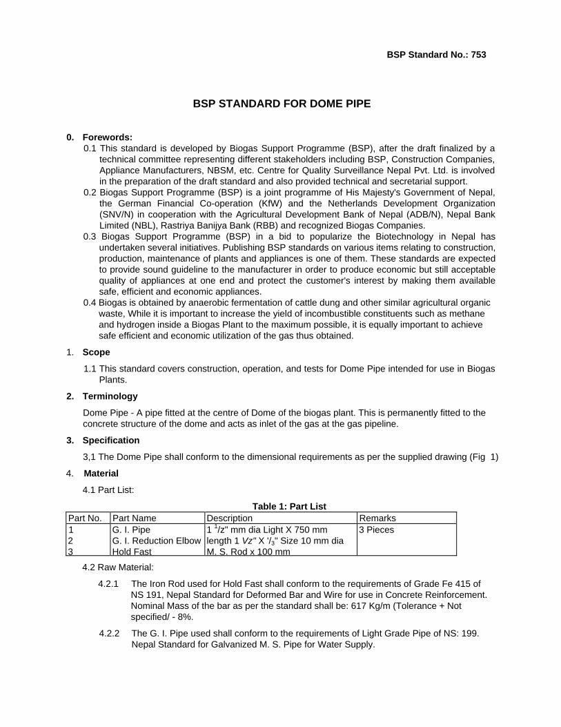
BSP STANDARD FOR DOME PIPE
0. Forewords: 0.1 This standard is developed by Biogas Support Programme (BSP), after the draft finalized by a
technical committee representing different stakeholders including BSP, Construction Companies, Appliance Manufacturers, NBSM, etc. Centre for Quality Surveillance Nepal Pvt. Ltd. is involved in the preparation of the draft standard and also provided technical and secretarial support.
0.2 Biogas Support Programme (BSP) is a joint programme of His Majesty's Government of Nepal, the German Financial Co-operation (KfW) and the Netherlands Development Organization (SNV/N) in cooperation with the Agricultural Development Bank of Nepal (ADB/N), Nepal Bank Limited (NBL), Rastriya Banijya Bank (RBB) and recognized Biogas Companies.
0.3 Biogas Support Programme (BSP) in a bid to popularize the Biotechnology in Nepal has undertaken several initiatives. Publishing BSP standards on various items relating to construction, production, maintenance of plants and appliances is one of them. These standards are expected to provide sound guideline to the manufacturer in order to produce economic but still acceptable quality of appliances at one end and protect the customer's interest by making them available safe, efficient and economic appliances.
0.4 Biogas is obtained by anaerobic fermentation of cattle dung and other similar agricultural organic waste, While it is important to increase the yield of incombustible constituents such as methane and hydrogen inside a Biogas Plant to the maximum possible, it is equally important to achieve safe efficient and economic utilization of the gas thus obtained.
1. Scope
1.1 This standard covers construction, operation, and tests for Dome Pipe intended for use in Biogas Plants.
2. Terminology
Dome Pipe - A pipe fitted at the centre of Dome of the biogas plant. This is permanently fitted to the concrete structure of the dome and acts as inlet of the gas at the gas pipeline.
3. Specification
3,1 The Dome Pipe shall conform to the dimensional requirements as per the supplied drawing (Fig 1)
4. Material
4.1 Part List:
Table 1: Part List Part No. Part Name Description Remarks 1 2 3
G. I. Pipe G. I. Reduction Elbow Hold Fast
1 1/z" mm dia Light X 750 mm length 1 Vz" X '/3" Size 10 mm dia M. S. Rod x 100 mm
3 Pieces
4.2 Raw Material:
4.2.1 The Iron Rod used for Hold Fast shall conform to the requirements of Grade Fe 415 of NS 191, Nepal Standard for Deformed Bar and Wire for use in Concrete Reinforcement. Nominal Mass of the bar as per the standard shall be: 617 Kg/m (Tolerance + Not specified/ - 8%.
4.2.2 The G. I. Pipe used shall conform to the requirements of Light Grade Pipe of NS: 199. Nepal Standard for Galvanized M. S. Pipe for Water Supply.
41
BSP Standard No.: 753 Some specific features of the pipe shall be as follows: i. Mass: 3.25 Kg/m (Tolerance: +10% to -8%) ii. Thickness: 2.9 mm (Tolerance: + Not limited, - 8%) iii. Outside diameter: In between 47.8 and 48.4 mm iv. Zinc Coating: 400 gm/ m2 v. The thread mating with the reducer shall be taper thread conforming to the
requirements of IS; 554: 1985, Indian Standard for Dimension for Pipe thread where pressure tight joints are made on threads.
4.2.3 The G.I. Reduction Elbow shall conform to the requirements of IS: 1879: 1987, Indian Standard for Specification for Malleable Cast Iron Pipe Fittings. Some specific features of the elbow shall be as follows; i. Mass of the elbow: 25 kg/100 pieces ii. Mass of Zinc coating: 610 gm/ m2 iii. The thread of the reducer shall be parallel thread conforming to the requirements of
iv:554: 1985. Indian Standard for Dimension for Pipe thread where pressure tight joints are made on threads.
5. Recommended Manufacturing Process 5.1 Cut the G.I Pipe to the required length. 5.2 Cut external taper thread at one end up to 18 mm long. 5.3 Fit the reducer elbow to the threaded part of the G. I. Pipe. The joint between pipe and elbow
must be absolutely gas tight. As sealing agent different material such as teflon tape. Zinc paste, or Jute & paint individual or in combination may be used by the supplier as appropriate
5.4 Weld three numbers of Iron Rods to the pipe at a distance of 50 mm from the other end. The rods shall be radially placed along the circumference of the pipe making an angle of 120° to each other. A jig may be used to position the M. S. rods. Complete the tack welding and remove the piece form the
5.5 Complete the full welding.
6. Workmanship and Finish 6.1 The Dome pipe shall be made from good quality pipe, elbow and rods. The parts shall be free
from any defects detrimental to the functioning of the dome pipe 6.2 The threading shall be well cut. dean and correct. 6.3 The welding shall be of good and sound quality. The welding shall be properfy cleaned to remove
the presence of any flux. 6.4 The surface of the dome pipe shall be smooth, without any blur, projections or protrusion. Any
sharp edge shall be suitably removed.
7. In Process Quality Control The manufacturer shall consistently check the quality of the product during various stages of its manufacturing. Quality control at following points are recommended, however depending upon the procedure followed the manufacturer may include other suitable points also: 7.1 Raw Material: The supplier shall check the quality of raw material, for example: pipe, elbow and
rods to ensure that they meet the requirements stipulated in Clause 4.2. 7.2 Length: Length of the G I. Pipe and M. S. Rod shall be regularly checked. 7.3 Thread on G. I. Pipe: Thread on G. I. Pipe shall be checked to ensure good quality threading. 7.4 Welding: Quality of the welding between the welds between the hold fast and G. I. Pipe shall be
regularly checked,
7.5 Quality Plan: The supplier shall prepare a quality plan describing exactly how the specification and other quality requirements specified in this standard will be met. The plan shall clearly specify different inspection/ control points. The supplier shall maintain records of dimensional checks, visual inspection and other tests carried as a proof of conformance of the product to the requirements of this standard. The supplier shall preserve and present these records to BSP representative/ s when visits for quality checking are made.

42
BSP Standard No.: 753
8. Performance 8.1 The domepipe after complete assembly shall pass the pressure test specified in Annex A of the
standard. 8.2 The supplier shall test 100% of the dome pipe to the pressure test.
9. Sampling This sampling plan shall be followed for any lot wise inspection of the products for the purpose of lot acceptance. 9.1 Batch: All of the products made from one source of raw material purchased at one time shall
constitute a batch. 9.2 Lot: A number of products offered for inspection at one time and manufactured from the raw
material from same source shall constitute a lot. Maximum and recommended lot size shall be 500 units of dome pipe.
9.3 Defective Sample: Any sample not conforming to any one or more of the specified requirements. 9.4 Random Sampling: A random sampling method ensuring that every piece of products offered for
inspection shall have equal probability for being selected as a sample shall be followed. Either of the two random sampling method shall be followed: |. Systematic Sampling: II. Use of Random sampling table:
9.5 Sampling Plan for Visual Inspection and Dimensional Check: i. Sampling Plan
Table 2. Sampling Plan Lot size (a) Sample Size (b) Acceptance No.
(c)Rejection No.
(d)1- 15 3 0 1 16-90 13 1 2 91- 150 20 2 3 151-280 32 3 4 281-500 50 5 6
ii. Criteria for conformity: For the lot size specified in column (a) of the above table sample size specified in column (b) shall be inspected for visual and dimensional requirements. If the number of defective samples is less or equal to the number mentioned in column c then the lot shall be considered conforming to the requirements of this standard in visual and dimensional requirements, if the total number of defective samples is equal to or more than the number mentioned in column d then the lot shall be considered not conforming to the requirements of this standard.
9.6 Sampling Plan for Performance Tests: 1 sample per 100 pieces of dome pipe offered for inspection shall be tested for the performance test specified in Clause 8.1 of this standard. All the tested samples shall pass the specified tests for the lot to be accepted.
10. Marking Every piece of Dome Pipe shall permanently be marked with the following information. 10.1 Manufacturers Name/ or logo/ or any other identification. 10.2 BSP Approved/ Supplied Identification tag at a place indicated in Figure 1. 10.3 Batch No.

43
BSP Standard No.: 753
11. Packing
In normal condition, the dome pipe does not require any packing. They shall be appropriately tied, the Joint between the reducer elbow and the G. I. Pipe appropriately protected so that the dome pipes do not damage during storage and transportation.
12. Reference List
12.1 NS: 191, Nepal Standard for Deformed Bar and Wire for use in Concrete Reinforcement.
12.2 NS: 199, Nepal Standard for Galvanized M. S. Pipe for Water Supply.
12.3 IS: 554, Indian Standard for Dimension for Pipe thread where pressure tight joints are made on threads.
12.4 IS: 1879. Indian Standard -Specification for Malleable Cast Iron Pipe Fittings.
12.5 IS: 4736, Indian Standard - Hot Dip Zinc Coatings on Mild Steel Tubes.
12.6 IS 4759, Indian Standard - Hot Dip Zinc Coatings On Structural Steel and Other Allied Products - Specification.
12.7 BSP drawing
12.8 Other BSP Publications.
44
BSP Standard No.: 766
BSP STANDARD fOR
GAS PIPE LINE ADAPTOR
Biogas Support Programme
PO Box 1966, Kathmandu,
Nepal

45BSP Standard No.: 766
BSP STANDARD FOR GAS PIPE LINE ADAPTOR
0. Forewords:
0.1 This standard is developed by Biogas Support Programme (BSP), after the draft finalized by a technical committee representing different stakeholders including BSP, Construction Companies, Appliance Manufacturers, NBSM, etc. Centre for Quality Surveillance Nepal Pvt. Ltd. is involved in the preparation of the draft standard and also provided technical and secretarial support.
0.2 Biogas Support Programme (BSP) is a joint programme of His Majesty's Government of Nepal, the German Financial Co-operation (KfW) and the Netherlands Development Organization (SNV/N) in cooperation with the Agricultural Development Bank of Nepal (ADB/N). Nepal Bank Limited (NBL), Rastriya Banijya Bank (RBB) and recognized Biogas Companies.
0.3 Biogas Support Programme (BSP) in a bid to popularize the Biotechnology in Nepal has undertaken several initiatives. Publishing BSP standards on various items relating to construction, production, maintenance of plants and appliances is one of them. These standards are expected to provide sound guideline to the manufacturer in order to produce economic but still acceptable quality of appliances at one end and protect the customer's interest by making them available safe, efficient and economic appliances
0,4 Biogas is obtained by anaerobic fermentation of cattle dung and other similar agricultural organic waste. While it is important to increase the yield of incombustible constituents such as methane and hydrogen inside a Biogas Plant to the maximum possible, it is equally important to achieve safe, efficient and economic utilization of the gas thus obtained
1. Scope
1.1 This standard covers construction, operation, and tests for Gas Pipe Line Adapter intended for use in operating Biogas pipelines to enable to attach an external device in the gas pipeline, for example pressure gage.
2. Terminology Gas Pipeline Adapter - A device which can be fitted at an appropriate place to enable attach an external device in the gas pipeline.
Rubber Hose Holder - A part in the Gas pipeline adapter in which a rubber hose can be fitted.
3. Specification:
3.1 The Gas Pipe Line Adapter shall conform to the dimensional requirements as per the supplied drawing (Fig. 1).
4. Material
4 1 Part List: Table 1: Part List of Gas Pipe Line AdapterPart No, Part Name Description Remarks 1 2
Rubber Hose Holder Vehicle Tube Valve Body
Cast or drawn Brass Rod Cast or drawn Brass Rod

46BSP Standard No.: 766
4.2 Raw Material:
4.2.1 1 Brass Parts: Recommended material used to manufacture the Brass parts of Gas Pipe Line Adapter shall conform to the requirements of Designation LCB2 of IS: 292- 1983. Specification of Leaded Brass Ingots and Castings. Any other suitable brass material also may be used for the purpose. Some properties of recommended material and another suitable material (as an example) is given in following table:
s. Characteristics LCB2 of IS 292 Alternate {example N only) 1 Chemical Composition i. Copper plus incidental Nickel 63.0 to 70.0% 59.0 to 62.0% ti. Lead 1.0 to 1.3% 0.5 to 1.0% iii. Tin 1.50% Max. 0.5 to 1.0% iv. Iron 0.75%, Max. 0.1% Max. v. Aluminium 0.01%, Max. #** vi. Other impurities *** 0.2% Max. vii.Zinc Remainder Remainder 2 Physical Properties i. Tensile Strength 345 N/ mm2 ii. %Elongation 20%. Min
Castings and brass rod shall be free from any viual defects and shall be sound, free from laps, blowholes and pitting, and the surface shall be clean and smooth.
5. Recommended Manufacturing Process 5.1 Cut the brass bars to the required length 5.2 Complete operations like internal boring, step cutting, thread cutting, etc. in the lathe machine. 5.3 Assemble the Gas Pipe Line Adapter by fitting the mating parts of Rubber Hose Holder and Vehicle
Tube Valve Body. 5.4 Complete the fitting by Pb Sn Soldering of the jointed parts-
6. Workmanship and Finish: 6.1 The Gas Pipe Line Adapter shall be made from good quality brass rods. The brass rod shall be free
from any casting defects detrimental to the functioning of the adapter 6.2 The soldering joint shall be of good and sound quality. The joint shall be properly cleaned. 6.3 The surface of the Adapter shall be smooth, without any blur, projections or protrusion. Any sharp
edges shall be suitably removed.
7. In Process Quality Control The manufacturer shall consistently check the quality of the product during various stages of us manufacturing. Quality control at following points are recommended, however depending upon the procedure followed the manufacturer may include other suitable points also
7.1 Raw Material: The supplier shall check the quality of raw material to ensure that they meet the requirements stipulated in clause 4.2.
7.2 Dimension: The dimensions of the finished product shall be strictly controlled and reguiarly checked to ensure that they conform to the dimensional requirements specified in the drawing (Fig 1).
7.3 Threading: Internal threading in the Vehicle Tube Valve body shall be checked after the process to ensure good quality threading.
7.4 Machining: Quality of the machining of the parts shall be checked immediately after each machining process. Parts shall be checked for any casting defects discovered during the process of machining, which was not predominant before machining
7.5 Soldering Joint: Quality of the soldering joint between the two parts shall be checked after the process of soldering is completed.
7.6 Quality Plan: The supplier shall prepare a quality plan describing exactly how the specification and other quality requirements specified in this standard will be met. The plan shall clearly specify different inspection/ control points. The supplier shall maintain records of dimensional checks, visual inspection
7.7
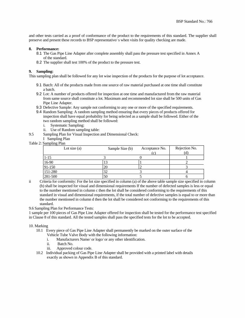
47BSP Standard No.: 766
and other tests carried as a proof of conformance of the product to the requirements of this standard. The supplier shall preserve and present these records to BSP representative/ s when visits for quality checking are made.
8. Performance: 8.1 The Gas Pipe Line Adapter after complete assembly shall pass the pressure test specified in Annex A
of the standard. 8.2 The supplier shall test 100% of the product to the pressure test.
9. Sampling: This sampling plan shall be followed for any lot wise inspection of the products for the purpose of lot acceptance.
9.1 Batch: All of the products made from one source of raw material purchased at one time shall constitute a batch.
9.2 Lot: A number of products offered for inspection at one time and manufactured from the raw material from same source shall constitute a lot. Maximum and recommended lot size shall be 500 units of Gas Pipe Line Adapter.
9.3 Defective Sample: Any sample not conforming to any one or more of the specified requirements. 9.4 Random Sampling: A random sampling method ensuring that every pieces of products offered for
inspection shall have equal probability for being selected as a sample shall be followed. Either of the two random sampling method shall be followed: i. Systematic Sampling: ii. Use of Random sampling table:
9.5 Sampling Plan for Visual Inspection and Dimensional Check: I Sampling Plan
Table 2: Sampling Plan Lot size (a) Sample Size (b) Acceptance No.
(c)Rejection No.
(d) 1-15 3 0 1 16-90 13 1 2 91-150 20 2 3 151-280 32 3 4 281-500 50 5 6
ii Criteria for conformity: For the lot size specified in column (a) of the above table sample size specified in column (b) shall be inspected for visual and dimensional requirements If the number of defected samples is less or equal to the number mentioned in column c then the lot shall be considered conforming to the requirements of this standard in visual and dimensional requirements, if the total number of defective samples is equal to or more than the number mentioned in column d then the lot shall be considered not conforming to the requirements of this standard.
9.6 Sampling Plan for Performance Tests: 1 sample per 100 pieces of Gas Pipe Line Adapter offered for inspection shall be tested for the performance test specified in Clause 8 of this standard. All the tested samples shall pass the specified tests for the lot to be accepted.
10. Marking 10.1 Every piece of Gas Pipe Line Adapter shall permanently be marked on the outer surface of the
Vehicle Tube Valve Body with the following information: i. Manufacturers Name/ or logo/ or any other identification. ii. Batch No. iii. Approved colour code.
10.2 Individual packing of Gas Pipe Line Adapter shall be provided with a printed label with details exactly as shown in Appendix B of this standard.
48BSP Standard No.; 766
11. Packing
Gas Pipe Line Adapter shall be packed in a BSP approved transparent material. A number of such water drains shall be suitably packed in a strong and suitable cardboard box.
12. Reference List: 12.1 IS: 292, Indian Standard - Specification for Leaded Brass Ingots and Castings. 12.2 IS: 554, Indian Standard - Dimensions for Pipe Threads where Pressure-Tight Joints are Made
on Threads. 12.3 BSP drawing. 12.4 Other BSP Publications.
49BSP Standard No.; 766
Appendix A
Procedure for Pressure Test:
Threaded end of the test piece shall be closed air-tight with a suitable end cap. The other end shall be connected to a device (for example air compressor) for applying a air pressure. The sample then shall be applied to a minimum internal air pressure of 0.5 Kg/ cm2 (49 x 103 N/m2), The test piece shall not so any sign of air leakage from any part, surface or mating surfaces during the test.
The air leakage can be tested by any suitable means such as by immersing the sample completely inside a water bath or by applying soap/ shampoo solution.
50BSP Standard No.: 754
BSP Standard
for
Mixer Installation and Manufacturing
Biogas Suppot Programme
PO Box 1966, Kathmandu,
Nepal

51BSP Standard No.: 754
MIXER INSTALLATION AND MANUFACTURING
0. Forewords:
0.1 This standard is developed by Biogas Support Programme (BSP), after the draft finalized by a technical committee representing different stakeholders including BSP, Construction Companies, Appliance Manufacturers, NBSM, etc. Centre for Quality Surveillance Nepal Pvt. Ltd. is involved in the preparation of the draft standard and also provided technical and secretarial support.
0. 2 Biogas Support Programme (BSP) is a joint programme of His Majesty's Government of Nepal, the German Financial Co-operation (KfW) and the Netherlands Development Organization (SNV/N) in cooperation with the Agricultural Development Bank of Nepal (ADB/N), Nepal Bank Limited (NBL), Rastriya Banijya Bank (RBB) and recognized Biogas Companies.
0.3 Biogas Support Programme (BSP) in a bid to popularize the Biotechnology in Nepal has undertaken several initiatives. Publishing BSP standards on various items relating to construction, production, maintenance of plants and appliances is one of them. These standards are expected to provide sound guideline to the manufacturer in order to produce economic but still acceptable quality of appliances at one end and protect the customer's interest by making them available safe, efficient and economic appliances.
0.4 Biogas is obtained by anaerobic fermentation of cattle dung and other similar agricultural organic waste. While it is important to increase the yield of incombustible constituents such as methane and hydrogen inside a Biogas Plant to the maximum possible, it is equally important to achieve safe, efficient and economic utilization of the gas thus obtained
1. Scope
1.1 This standard covers construction, manufacturing installation and tests of Mixer intended for use in Biogas plants.
2. Terminology Mixture - A device used to agitate the dung and water into the inlet pit of a biogas plant. The mixer after proper agitation of the dung and water shall make effective mixing. Vertical Mixer Bracket - A device used to support the Vertical Mixer Machine in the inlet pit. Vertical Mixer Bracket is permanently fixed in the concrete structure of the inlet pit, Vertical Mixer Machine - A device with fins of predetermined profile used to churn the dung and water in the inlet pit.
3. Specification
3.1 Dimensional requirements of different parts of the mixture shall be as per the drawing (Fig 1) and Fig 2.
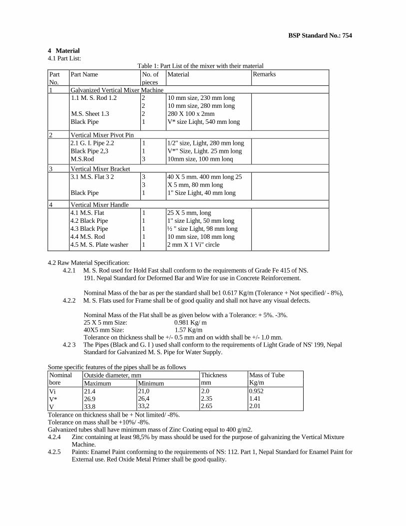
52BSP Standard No.: 754
4 Material 4.1 Part List:
Table 1: Part List of the mixer with their material Part No.
Part Name No. of pieces
Material Remarks
1 Galvanized Vertical Mixer Machine 1.1 M. S. Rod 1.2
M.S. Sheet 1.3 Black Pipe
2 2 2 1
10 mm size, 230 mm long 10 mm size, 280 mm long 280 X 100 x 2mm V* size Liqht, 540 mm long
2 Vertical Mixer Pivot Pin 2.1 G. I. Pipe 2.2
Black Pipe 2,3 M.S.Rod
1 1 3
1/2" size, Light, 280 mm long V*" Size, Light. 25 mm long 10mm size, 100 mm lonq
3 Vertical Mixer Bracket 3.1 M.S. Flat 3 2
Black Pipe
3 3 1
40 X 5 mm. 400 mm long 25 X 5 mm, 80 mm long 1" Size Light, 40 mm long
4 Vertical Mixer Handle 4.1 M.S. Flat
4.2 Black Pipe 4.3 Black Pipe 4.4 M.S. Rod 4.5 M. S. Plate washer
1 1 1 1 1
25 X 5 mm, long 1" size Light, 50 mm long ½ " size Light, 98 mm long 10 mm size, 108 mm long 2 mm X 1 Vi" circle
4.2 Raw Material Specification:
4.2.1 M. S. Rod used for Hold Fast shall conform to the requirements of Grade Fe 415 of NS. 191. Nepal Standard for Deformed Bar and Wire for use in Concrete Reinforcement.
Nominal Mass of the bar as per the standard shall be1 0.617 Kg/m (Tolerance + Not specified/ - 8%), 4.2.2 M. S. Flats used for Frame shall be of good quality and shall not have any visual defects.
Nominal Mass of the Flat shall be as given below with a Tolerance: + 5%. -3%. 25 X 5 mm Size: 0.981 Kg/ m 40X5 mm Size: 1.57 Kg/m
Tolerance on thickness shall be +/- 0.5 mm and on width shall be +/- 1.0 mm. 4.2 3 The Pipes (Black and G. I ) used shall conform to the requirements of Light Grade of NS' 199, Nepal
Standard for Galvanized M. S. Pipe for Water Supply.
Some specific features of the pipes shall be as follows Outside diameter, mm Nominal
bore Maximum MinimumThickness mm
Mass of Tube Kg/m
Vi V* V
21.4 26.9 33.8
21,0 26,4 33,2
2.0 2.35 2.65
0.952 1.41 2.01
Tolerance on thickness shall be + Not limited/ -8%. Tolerance on mass shall be +10%/ -8%. Galvanized tubes shall have minimum mass of Zinc Coating equal to 400 g/m2. 4.2.4 Zinc containing at least 98,5% by mass should be used for the purpose of galvanizing the Vertical Mixture
Machine. 4.2.5 Paints: Enamel Paint conforming to the requirements of NS: 112. Part 1, Nepal Standard for Enamel Paint for
External use. Red Oxide Metal Primer shall be good quality.
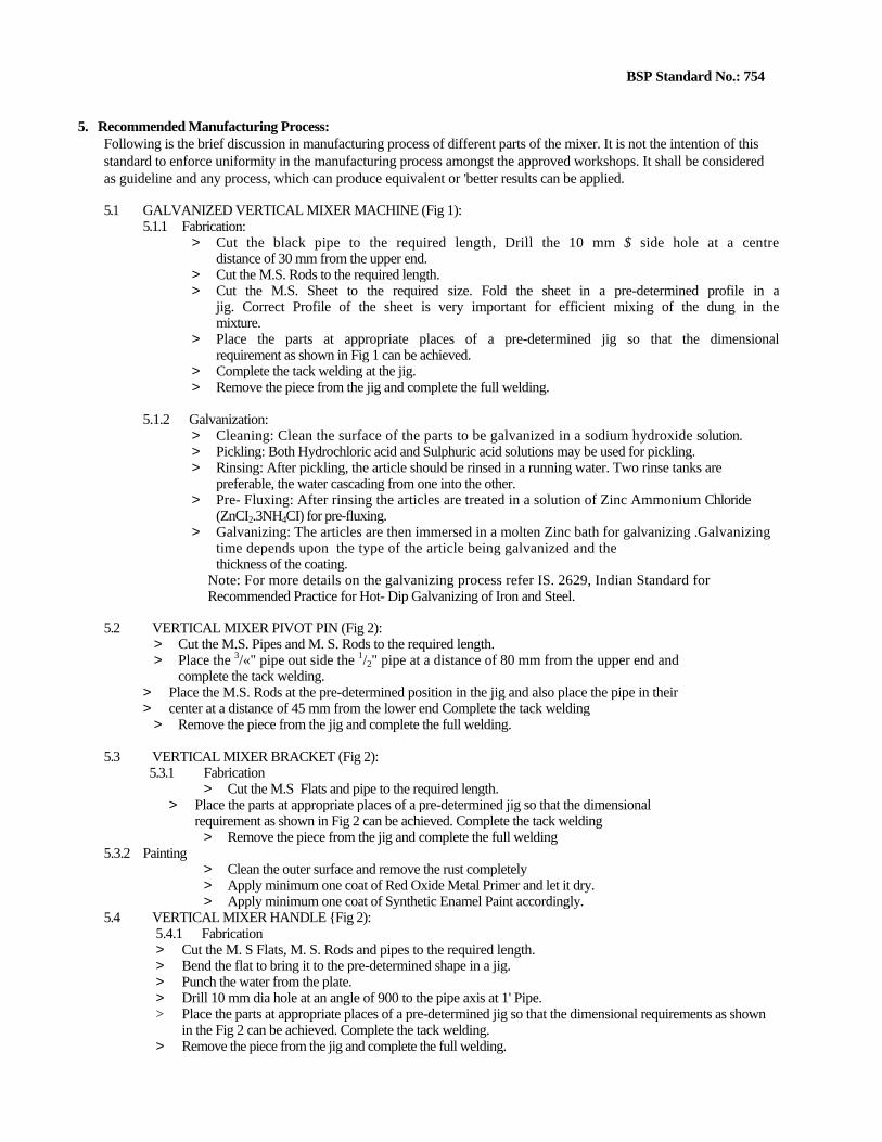
53BSP Standard No.: 754
5. Recommended Manufacturing Process: Following is the brief discussion in manufacturing process of different parts of the mixer. It is not the intention of this standard to enforce uniformity in the manufacturing process amongst the approved workshops. It shall be considered as guideline and any process, which can produce equivalent or 'better results can be applied.
5.1 GALVANIZED VERTICAL MIXER MACHINE (Fig 1): 5.1.1 Fabrication:
> Cut the black pipe to the required length, Drill the 10 mm $ side hole at a centre distance of 30 mm from the upper end.
> Cut the M.S. Rods to the required length. > Cut the M.S. Sheet to the required size. Fold the sheet in a pre-determined profile in a
jig. Correct Profile of the sheet is very important for efficient mixing of the dung in the mixture.
> Place the parts at appropriate places of a pre-determined jig so that the dimensional requirement as shown in Fig 1 can be achieved.
> Complete the tack welding at the jig. > Remove the piece from the jig and complete the full welding.
5.1.2 Galvanization: > Cleaning: Clean the surface of the parts to be galvanized in a sodium hydroxide solution. > Pickling: Both Hydrochloric acid and Sulphuric acid solutions may be used for pickling. > Rinsing: After pickling, the article should be rinsed in a running water. Two rinse tanks are
preferable, the water cascading from one into the other. > Pre- Fluxing: After rinsing the articles are treated in a solution of Zinc Ammonium Chloride
(ZnCI2.3NH4CI) for pre-fluxing. > Galvanizing: The articles are then immersed in a molten Zinc bath for galvanizing .Galvanizing
time depends upon the type of the article being galvanized and the thickness of the coating.
Note: For more details on the galvanizing process refer IS. 2629, Indian Standard for Recommended Practice for Hot- Dip Galvanizing of Iron and Steel.
5.2 VERTICAL MIXER PIVOT PIN (Fig 2): > Cut the M.S. Pipes and M. S. Rods to the required length. > Place the 3/«" pipe out side the 1/2" pipe at a distance of 80 mm from the upper end and
complete the tack welding. > Place the M.S. Rods at the pre-determined position in the jig and also place the pipe in their > center at a distance of 45 mm from the lower end Complete the tack welding
> Remove the piece from the jig and complete the full welding.
5.3 VERTICAL MIXER BRACKET (Fig 2): 5.3.1 Fabrication
> Cut the M.S Flats and pipe to the required length. > Place the parts at appropriate places of a pre-determined jig so that the dimensional
requirement as shown in Fig 2 can be achieved. Complete the tack welding > Remove the piece from the jig and complete the full welding
5.3.2 Painting > Clean the outer surface and remove the rust completely > Apply minimum one coat of Red Oxide Metal Primer and let it dry. > Apply minimum one coat of Synthetic Enamel Paint accordingly.
5.4 VERTICAL MIXER HANDLE {Fig 2): 5.4.1 Fabrication > Cut the M. S Flats, M. S. Rods and pipes to the required length. > Bend the flat to bring it to the pre-determined shape in a jig. > Punch the water from the plate. > Drill 10 mm dia hole at an angle of 900 to the pipe axis at 1' Pipe. > Place the parts at appropriate places of a pre-determined jig so that the dimensional requirements as shown
in the Fig 2 can be achieved. Complete the tack welding. > Remove the piece from the jig and complete the full welding.

54BSP Standard No.: 754
5.4.2 Painting > Clean the outer surface and remove the rust completely
> Apply one coat of Red Oxide Metal Primer and let it dry. Then apply another of Red Oxide Metal Primer and dry it again.
> Apply two coats of final coat of Synthetic Enamel Paint accordingly.
6. Process Quality Control The manufacturer shall consistently check the quality of the product during various stages of its manufacturing. Quality control at following points are recommended, however depending upon the procedure followed the manufacturer may include other suitable points also:
6.1 Raw Material: All the raw materials including Black & G. I. Pipes, M. S. Flats, M. S. Sheet, Paints, Zinc, etc. shall be checked to ensure that they conform to the requirements stipulated in Clause 4.2.
6.2 Length: Length of pipes, rods, flats shall be checked after the process of cutting in completed. 6.3 Side boring shall be checked for its position as well as its intersection with the main axis of the
pipe. 6.4 Quality of welding shall be checked during the welding of each part. 6.5 Dimension of the parts shall be checked as per the drawing after the completion of fabrication
work. 6.6 Quality Plan: The supplier shall prepare a quality plan describing exactly how the specification
and other quality requirements specified in this standard will be met. The plan shall clearly specify different inspection/ control points. The supplier shall maintain records of dimensional checks, visuai inspection and other tests carried as a proof of conformance of the product to the requirements of this standard. The supplier shall preserve and present these records to BSP representative/ s when visits for quality checking are made.
7. Workmanship and Finish: 7.1 The finish and workmanship of the mixer parts shall be of high quality 7.2 The surface shall be smooth, without any blur, projections or protrusion Any sharp edge shall be suitably
removed. 7.3 The Zinc coating shall be uniform, adherent, reasonably free from imperfections such as flux, ash, bare patches,
black spots, pimples, lumpiness, runs, rust stains, bulky white deposits and blisters.
8. Performance: 8.1 Galvanization: Mass of Zinc Coating in the Galvanized Vertical Mixer Machine shall be 610 g/m2
(minimum 8.2 The supplier shall test 3 samples from each batch of galvanization to check the mass of Zinc
Coating 8.3 Test Method shall be as per IS: 2633, Indian Standard for Methods for testing weight, thickness
and uniformity of coating on hot dipped galvanized articles.
9. Sampling This sampling plan shall be followed for any lot wise inspection of the products for the purpose of lot acceptance.
9.1 Batch: All of the products cast from one melt shall constitute a batch. 9.2 Lot: A number of products offered for inspection at one time and manufactured from the raw
material from same source shall constitute a lot. Maximum and recommended lot size shall be 500 sets of Mixer Set.
9.3 Defective Sample: Any sample not conforming to any one or more of the specified requirements. 9.4 Random Sampling; A random sampling method ensuring that every piece of products offered for
inspection shall have equal probability for being selected as a sample shall be followed. Either of the two random sampling method shall be followed; i. Systematic Sampling: ii. Use of Random sampling table:

55BSP Standard No: 754
9.5 Sampling Plan for Visual Inspection and Dimensional Check: i. Sampling Plan
Table 2: Sampling PlanLot size (a)
Sample Size (b) Acceptance No.(c)
Rejection No. (d)
1-15 3 0 1 16-90 13 1 2 91-150 20 2 3151-280 32 3 4281-500 50 5 6
ii. Criteria for conformity: For the lot size specified in column (a) of the above table sample size specified in column (b) shall be inspected for visual and dimensional requirements. If the number of defected samples is less or equal to the number mentioned in column c then the lot shall be considered conforming to the requirements of this standard in visual and dimensional requirements, if the total number of defective samples is equal to or more than the number mentioned in column d then the lot shall be considered not conforming to the requirements of this standard.
9,6 Sampling Plan for Performance Test: 3 samples per lot shall be tested for the performance test specified in Clause 8 of this standard. All 3 samples shall pass the specified tests for the lot to be accepted.
10. Marking Every part of the mixer shall permanently be marked with the following information: 10.1 Manufacturers Name/ or logo/ or any other identification. 10.2 Batch No. 10.3 Any other contractual requirements. 10.4 Approved colour code
11. Packing Mixer parts need not be packed in any form except that they may be tied for identification purpose and during transportation to avoid any possibility of damage
12. Reference List 12.1 NS: 191, Nepal Standard - Deformed Bar and Wire for use in Concrete Reinforcement. 12.2 NS: 199, Nepal Standard - Galvanized M. S. Pipe for Water Supply 12.3 NS: 112, Enamel Paint, Part 1- For external use. 12.4 IS: Indian Standard - Recommended Practice for Hot-Dip galvanizing of Iron and Steel 12.5 IS: 2633, Indian Standard - Testing weight, thickness and uniformity of coating on hot dipped
galvanized articles. 12.6 IS: 4736. Indian Standard - Hot Dip Zinc Coatings on Mild Steel Tubes. 12.7 IS 4759, Indian Standard, Hot Dip Zinc Coatings On Structural Steel arid Other Allied Products -
Specification. 12.8 BSP drawing 12.9 Other BSP Publications.
56
BSP Standard No.: 757
BSP Standard
for
Biogas Lamp (Ujeli)
Biogas Support Programme
PO Box 1966, Kathmandu,
Nepal
57
BSP Standard No.: 757
BIOGAS LAMP
0. Forewords: 0.1 This standard is developed by Biogas Support Programme (BSP), after the draft finalized by a technical committee
representing different stakeholders including BSP, Construction Companies, Appliance Manufacturers, NBSM. etc. Centre for Quality Surveillance Nepal Pvt. Ltd. is involved in the preparation of the draft standard and also provided technical and secretarial support.
0.2 Biogas Support Programme (BSP) is a joint programme of His Majesty's Government of Nepal, the German Financial Co-operation (KfW) and the Netherlands Development Organization (SNV/N) in cooperation with the Agricultural Development Bank of Nepal (ADB/N), Nepal Bank Limited (NBL), Rastriya Banijya Bank (RBB) and recognized Biogas Companies.
0.3 Biogas Support Programme (BSP) in a bid to popularize the Biotechnology in Nepal has undertaken several initiatives. Publishing BSP standards on various items relating to construction, production, maintenance of plants and appliances is one of them. These standards are expected to provide sound guideline to the manufacturer in order to produce economic but still acceptable quality of appliances at one end and protect the customer's interest by making them available safe, efficient and economic appliances,
0.4 Biogas is obtained by anaerobic fermentation of cattle dung and other similar agricultural organic waste. While it is important to increase the yield of incombustible constituents such as methane and hydrogen inside a Biogas Plant to the maximum possible, it is equally important to achieve safe, efficient and economic utilization of the gas thus obtained.
1. Scope
1.1 This standard covers construction, operation, safety requirements and tests Biogas Lamp (Ujeli) intended for use with Biogas.
2. Terminology
Air Sleeve - This contains a number of Air holes, which can be rotated to adjust and vary the gas and air ratio in the mantle holder.
Lamp- A device used to generate light by combustion of the gas
Mantle Holder- A part of the lamp, which is fitted with the carborendom Ventury where a mantle can be fitted. The holder consists of gas nozzle for the flow of the gas for combustion and air holes for proper mixing of gas and air.
Reflectors - These are heat and light reflectors fitted on top of the lamp so that heat and light produced at the mantle is reflected below and the flow of heat through the lamp top is retarded. 3. Specification
3.1 The Biogas Lamp (Ujeli type, approved by BSP) shall conform to the dimensional requirements as per the supplied drawing (Fig. 1)
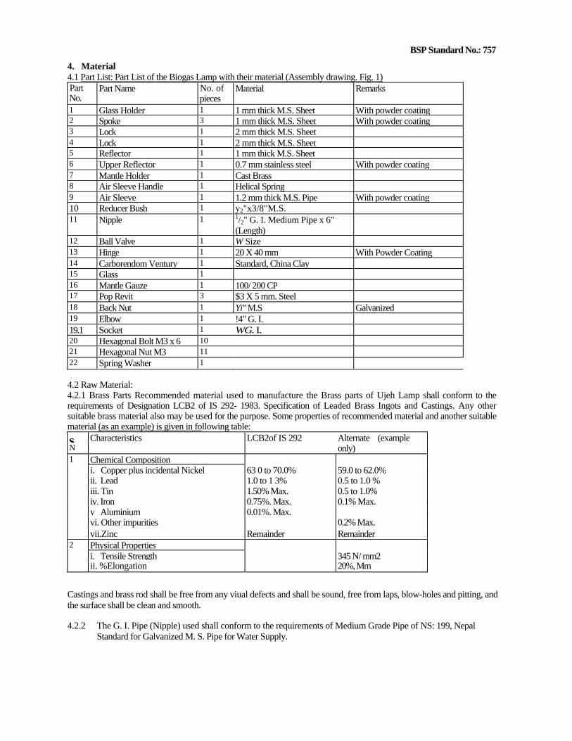
58BSP Standard No.: 757
4. Material 4.1 Part List: Part List of the Biogas Lamp with their material (Assembly drawing. Fig. 1) Part No.
Part Name No. of pieces
Material Remarks
1 Glass Holder 1 1 mm thick M.S. Sheet With powder coating 2 Spoke 3 1 mm thick M.S. Sheet With powder coating 3 Lock 1 2 mm thick M.S. Sheet4 Lock 1 2 mm thick M.S. Sheet5 Reflector 1 1 mm thick M.S. Sheet6 Upper Reflector 1 0.7 mm stainless steel With powder coating 7 Mantle Holder 1 Cast Brass8 Air Sleeve Handle 1 Helical Spring9 Air Sleeve 1 1.2 mm thick M.S. Pipe With powder coating 10 Reducer Bush 1 y2"x3/8"M.S. 11 Nipple 1 1/2" G. I. Medium Pipe x 6"
(Length)
12 Ball Valve 1 W Size13 Hinge 1 20 X 40 mm With Powder Coating 14 Carborendom Ventury 1 Standard, China Clay15 Glass 1 16 Mantle Gauze 1 100/ 200 CP17 Pop Revit 3 $3 X 5 mm. Steel 18 Back Nut 1 Yi" M.S Galvanized19 Elbow 1 !4" G. I.19.1 Socket 1 WG. I.20 Hexagonal Bolt M3 x 6 10 21 Hexagonal Nut M3 11 22 Spring Washer 1
4.2 Raw Material: 4.2.1 Brass Parts Recommended material used to manufacture the Brass parts of Ujeh Lamp shall conform to the requirements of Designation LCB2 of IS 292- 1983. Specification of Leaded Brass Ingots and Castings. Any other suitable brass material also may be used for the purpose. Some properties of recommended material and another suitable material (as an example) is given in following table: s. Characteristics LCB2of IS 292 Alternate (example N only) 1 Chemical Composition i. Copper plus incidental Nickel 63 0 to 70.0% 59.0 to 62.0% ii. Lead 1.0 to 1 3% 0.5 to 1.0 % iii. Tin 1.50% Max. 0.5 to 1.0% iv. Iron 0.75%. Max. 0.1% Max. v Aluminium 0.01%. Max. vi. Other impurities 0.2% Max. vii.Zinc Remainder Remainder 2 Physical Properties i. Tensile Strength 345 N/ mm2 ii. %Elongation 20%, Mm
Castings and brass rod shall be free from any viual defects and shall be sound, free from laps, blow-holes and pitting, and the surface shall be clean and smooth.
4.2.2 The G. I. Pipe (Nipple) used shall conform to the requirements of Medium Grade Pipe of NS: 199, Nepal Standard for Galvanized M. S. Pipe for Water Supply.

59BSP Standard No.: 757
Some specific features of the pipe shall be as follows: i. Mass: 0.961 Kg/m (Tolerance: +10% to-8%) ii. Thickness: 2.65 mm (Tolerance: + Not limited, - 8%) iii. Outside diameter; In between 21.0 and 21.8 mm iv. Zinc Coating: 400 gm/ m2 v. The thread shall be taper thread conforming to the requirements of IS: 554: 1985, Indian Standard for Dimension or
Pipe thread where pressure tight joints are made on threads.
4.2.3 The G.I. Elbow shall conform to the requirements of IS: 1879: 1987, Indian Standard for Specification for Malleabfe Cast Iron Pipe Fittings. Some specific features of the elbow shall be as follows; i. Mass of the elbow: 9.1 kg/100 pieces ii. Mass of Zinc coating: 610 gm/ m2 iii. The thread of the reducer shall be parallel thread conforming to the requirements of IS: 554: 1985, Indian Standard
for Dimension for Pipe thread where pressure tight joints are made on threads. 4.2.4 The G.I. Socket shall conform to the requirements of IS: 1879: 1987, Indian Standard for
Specification for Malleable Cast Iron Pipe Fittings. Some specific features of the elbow shall be as follows: iv. Mass of the elbow: 6.1 kg/100 pieces v. Mass of Zinc coating: 610 gm/ m2 vi. The thread of the reducer shall be parallel thread conforming to the requirements of IS: 554: 1985, Indian Standard
for Dimension for Pipe thread where pressure tight joints are made on threads. 4.2.5 All the other raw material like M S. Sheet, Stainless steel. Spring. Glass. Revit,
Carborendom, etc. also shall be of standard quality and free from any defect affecting proper functioning of the lamp.
4.2.6 Mantle Gage shall conform to the requirements of IS. 2788. Indian Standard for Specification for Gas Mantles.
Recommended Manufacturing Procedure Following is the brief discussion in manufacturing process of different parts of the tamp It is not the intention of this standard to enforce uniformity in the manufacturing process amongst the approved workshops. It shall be considered as guideline and any process, which can produce equivalent or better results can be applied.
5.1 Mantle Holder: This is one of the critical parts of the lamp. Conformance to the required drawing (Fig 2) is very important.
> Take the pre-cast brass rod and carry out various operations like facing, turning, grooving, drilling, thread cutting (outside and inside), etc as per the dimensional requirements as shown in Fig. 2 in the lathe machine.
> Critical operation is the drilling of jet hole. Diameter and concentricity of the jet hole shall be accurately maintained.
> Appropriate jig has to be made to drill 12 Nos. of Air holes Drilling operation is to be completed as per predetermined position by jig.
5.2 Air Sleeve: > Cut the M.S. Pipe to the required length, clear out pipe seam projection along the pipe inside, > Drill 12 Nos. of Air holes in a drilling machine with the help of appropriate jig. > Affix the helical spring at appropriate place by brazing.
5.3 Lower Reflectors: > Cut the M.S. Sheet to the required diameter. > Punch the central hole > Drill the holes tj>3.2 mm as per the drawing and t|>3 mm for turning lock. > Apply Powder coating.
5.4 Upper Reflector: > Cut the stainless steel sheet to the required diameter > Drill the holes 4*3.2 mm as per the drawing and <|>3 mm for turning lock.
5.5 Other Components: According manufacture other components of the lamp to meet the stipulated requirements.
60BSP Standard No.: 757
6. In Process Quality Control The manufacturer shall consistently check the quality of the product during various stages of its manufacturing. Quality control at following points are recommended, however depending upon the procedure followed the manufacturer may include other suitable points also:
6.1 Raw Material: Raw Material shall be checked to ensure that they conform to the requirements of Clause 4.2. 6.2 Mantle Holder Mantle Holder shall be checked as follows: i. Diameter and concentricity of jet hole. ii. Quality and measurement of inside and outside thread iir. Length and diameter of sleeve jv. Position and diameter of Air holes. v. Quality of the machining.
6.3 Air Sleeve: i. Inside diameter of the sleeve ii Position and diameter of Air holes. iii Position and quality of handle. Quality of brazing.
6.4 Reflectors: i Position and diameter of central hole of upper reflector. ii Position and diameter of holes for turning lock and hinges in upper reflector. iii Position and diameter of holes for spoke, hinges for lower reflector iv. Centre distance between holes of lock holes and hinge holes. v. Dimensional measurements of Lock set. vi Quality of powder coat on the lower reflectors.
6.5 Spokes and Glass holder: i. Dimensional requirements of spokes. ii. Position and diameter of holes on spokes. iii. Profile (V- shape) of spokes. iv Dimensional requirements of glass holder. v, Quality of Powder coat on the spokes and glass holder
6-6 Assembly: The lamps shall be assembled completely to check the quality of fitting.
6.7 Quality Plan: The supplier shall prepare a quality plan describing exactly how the specification and other quality requirements specified in this standard will be met. The plan shall clearly specify different inspection/ control points. The supplier shall maintain records of dimensional checks, visual inspection and other tests carried as a proof of conformance of the product to the requirements of this standard. The supplier shall preserve and present these records to BSP representative/ s when visits for quality checking are made.
7. Workmanship and Finish: 7.1 The finish and workman ship of the lamp parts shall be of high quality. 7.2 The surface of the lamp shall be smooth, without any blur, projections or protrusion. Any sharp
edge shall be suitably removed. '7.3 There shall be no leakage of gas from threaded joints of the lamp assembly.
8. Sampling: This sampling plan shall be followed for any lot wise inspection of the products for the purpose of lot acceptance.
8.1 Batch: All of the products cast from one melt shall constitute a batch. 8.2 Lot: A number of products offered for inspection at one time and manufactured from the raw
material from same source shall constitute a lot. Maximum and recommended lot size shall be 500 sets of Ujeli lamp.
8.3 Defective Sample: Any sample not conforming to any one or more of the specified requirements. 8.4 Random Sampling: A random sampling method ensuring that every pieces of products offered for
inspection shall have equal probability for being selected as a sample shall be followed. Either of the two random sampling method shall be followed:
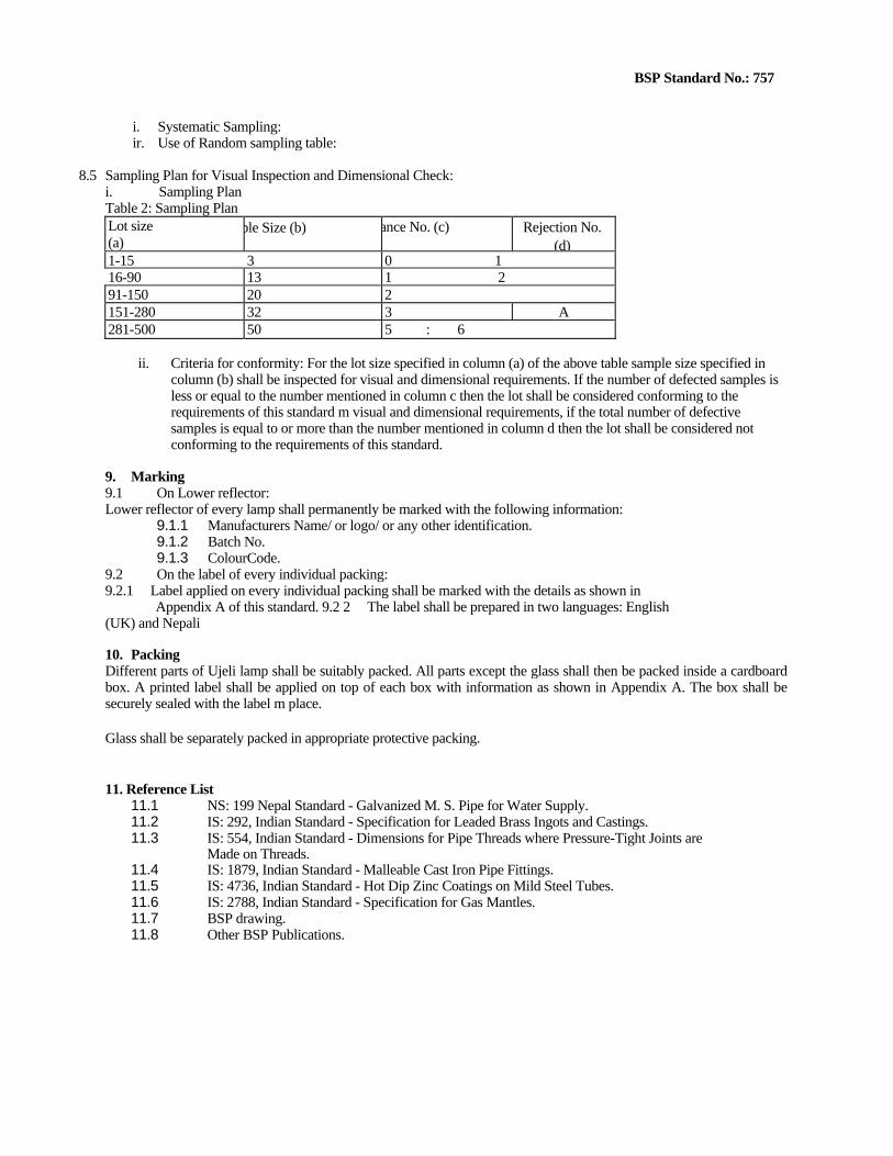
61BSP Standard No.: 757
i. Systematic Sampling: ir. Use of Random sampling table:
8.5 Sampling Plan for Visual Inspection and Dimensional Check: i. Sampling Plan Table 2: Sampling Plan Lot size (a)
ple Size (b) ance No. (c) Rejection No. (d)
1-15 3 0 116-90 13 1 291-150 20 2151-280 32 3 A281-500 50 5 : 6
ii. Criteria for conformity: For the lot size specified in column (a) of the above table sample size specified in column (b) shall be inspected for visual and dimensional requirements. If the number of defected samples is less or equal to the number mentioned in column c then the lot shall be considered conforming to the requirements of this standard m visual and dimensional requirements, if the total number of defective samples is equal to or more than the number mentioned in column d then the lot shall be considered not conforming to the requirements of this standard.
9. Marking 9.1 On Lower reflector: Lower reflector of every lamp shall permanently be marked with the following information:
9.1.1 Manufacturers Name/ or logo/ or any other identification. 9.1.2 Batch No. 9.1.3 ColourCode.
9.2 On the label of every individual packing: 9.2.1 Label applied on every individual packing shall be marked with the details as shown in
Appendix A of this standard. 9.2 2 The label shall be prepared in two languages: English (UK) and Nepali
10. Packing Different parts of Ujeli lamp shall be suitably packed. All parts except the glass shall then be packed inside a cardboard box. A printed label shall be applied on top of each box with information as shown in Appendix A. The box shall be securely sealed with the label m place.
Glass shall be separately packed in appropriate protective packing.
11. Reference List 11.1 NS: 199 Nepal Standard - Galvanized M. S. Pipe for Water Supply. 11.2 IS: 292, Indian Standard - Specification for Leaded Brass Ingots and Castings. 11.3 IS: 554, Indian Standard - Dimensions for Pipe Threads where Pressure-Tight Joints are
Made on Threads. 11.4 IS: 1879, Indian Standard - Malleable Cast Iron Pipe Fittings. 11.5 IS: 4736, Indian Standard - Hot Dip Zinc Coatings on Mild Steel Tubes. 11.6 IS: 2788, Indian Standard - Specification for Gas Mantles. 11.7 BSP drawing. 11.8 Other BSP Publications.