quality - weebly
TRANSCRIPT

QUALITY
CENTER FOR WORKFORCE DEVELOPMENT
Version :: CUCWD 107 :: Rev 1 2013
This material is based upon work supported by the National Science Foundation under Grant Number DUE-1104181. Any opinions, findings, and conclusions or recommendations expressed in this material are those of the author(s) and do not necessarily reflect the views of the National Science Foundation.
Copyright © 2013 Clemson University Center for Workforce Development. All Rights Reserved.* License information for illustrations and photographs in this document can be found in the Attribution Table in the Open Text for this particular module.
MODULE 22

Version :: CUCWD 101 :: Rev 1 2012
Page intentionally left blank

1
CENTER FOR WORKFORCE DEVELOPMENT
QUALITY22
11
22 Popular Measuring Instruments
Differentiate the measurement system being used on each of the tools discussed Locate, identify and label the parts of a vernier caliper, micrometer, and vernier
micrometer Compare and contrast various scales and tools Correctly record measurement readings from an English, metric, and vernier scale Formulate a plan explaining the measurement process for a scale, vernier caliper,
micrometer and vernier micrometer Apply these tools and their precision measurement capabilities to real-world scenarios.
Knowing how to use precision measuring tools is an important skill to have in the manufacturing environment. These tools are designed to read precise and accurate measurements, important for jobs where such precision is needed for quality control, customer satisfaction, durability and safety.
Consider the precision needed for manufacturing each component of an automobile.
INTRODUCTION
OBJECTIVES
ORIENTING QUESTIONS
What is precision measurement? In the manufacturing environment, why is it important to produce parts that meet the
specified design measurements? Have you ever used a linear measuring tool? If so, how precise was your measurement?
The learner will be able to:
Version :: CUCWD 101 :: Rev 1 2012

QUALITY22CENTER FOR WORKFORCE DEVELOPMENT
Version :: CUCWD 107 :: Rev 1 2013
Types of Measuring Tools
There are many different types of precision measuring instruments, some more accurate than others. You have probably already used at least one of the tools we will cover in this module. For example, you might have used a ruler or measuring tape for a home improvement project such as building a bird house or hanging a picture frame like in Figure 1(a).
Industry also uses similar precision measurements in the manufacturing of products. How-ever, unlike in the home, some of these measurements need to be accurate up to a millionth (0.000001) of an inch. Industry standards need to be accurate in order to maintain quality standards to satisfy customers and ensure safety. The appropriate tool should be selected not only based on the type of measurement (linear or mass, for example), but also considering the precision needed for the task at hand. Figure 1(b) shows a robotic laser used to provide preci-sion measurements across multiple surfaces of an object.
2
What are some of the types of measuring tools you are familiar with?
Activity 22.1.0
22.1
Figure 1. Measurement scenarios
(b) A robotic laser aligned device that provides pre-cise measurements across multiple surfaces.
(a) Man measuring wood plankfor home improvement project.
The rest of this module will present a comprehensive profile of regularly used linear mea-surement instruments with their respective limitations. It will also familiarize the student with their proper manipulation of these instruments.

QUALITY22CENTER FOR WORKFORCE DEVELOPMENT
Version :: CUCWD 107 :: Rev 1 2013
The first tools this module will cover are scales and rules. The machinist’s scale, or steel rule, is a 6-in. ruler and is the most common and simplest linear measuring instrument found in a machine shop. On one of its edges, each inch is divided into 32 equal segments, or 32nds of an inch. On the other side of the rule, each inch is divided into 64 equal segments, or 64ths of an inch. Scales that have units of measurements in the metric system are called metric scales. Figure 2 shows a machinist’s scale along with other types of rules and scales including the tape rule, the architect’s scale, and the engineer’s scale.
Figure 2. Types of rules and scales
3
22.0 Scales and Rules
(a) Machinist’s Scale
(b) Tape rule
The architects’ and engineers’ scales are used to interpret blueprints of structures and con-structs. Both scales are triangular as shown in Figure 2(c) and 2(d). There are six scales on the engineer’s scale which measure 10, 20, 30, 40, 50 and 60 parts to the inch. For example, in the 30 parts to the inch scale, one inch is divided into 30 parts and each division represents 1/30 in. The architect’s scale has 11 scales which measure 3/32, 3/16, 1/8, 1/4, 1/2, 1, 3/8, 3/4, 1-1/2, 3 inches to the foot, with one edge graduated to 16ths of an inch. For example, using the 1/4 scale, every 1/4 of an inch on the blueprint represents one foot.
(c) Architect’s scale
(d) Engineer’s scale
(a) Machinist’s Scale
(b) Tape rule

QUALITY22CENTER FOR WORKFORCE DEVELOPMENT
Version :: CUCWD 107 :: Rev 1 20134
22.2.1 READING A SCALE OR RULE
Scales are most useful for frequent and quick measurements. Reading a scale or rule is a valu-able skill to have. It is important that you master this skill before you start working with other measuring instruments. Below are guidelines that will help you master this skill.
STEP 1: Determine the Measuring System
First, you must decide whether you will measure an object using the English system (inches, feet) or the metric system (centimeters, meters). Your choice of measuring system will depend on your type of work. For example, if you work at BMW, you will need to understand and mea-sure using the metric system. If you work at General Electric, you will need to understand and measure using the English system. If you are an aircraft maintenance technician, the measure-ments you take will be in the English system. And, if you are an automotive technician, you will need to understand both the English and metric system and the relationship between the two as many cars use both measuring systems because their parts are manufactured around the world.
Most common scales and rules have two measurements, one on each of their edges. As dis-cussed earlier, a machinist’s rule, for example, has two measurements in inches but differing in the number of graduations per inch. Other scales and rules have one set of measurements in inches and the second in centimeters.
STEP 2: Determine the Size of Scale or Rule to Use
Common rules and scales can measure objects up to 12 in. or 30.5 cm. If you need to measure an object longer than that, you will need to use a yard stick for the English system, a meter stick for the metric system, or a tape rule that has both measuring systems.
STEP 3: Examine the graduations on the scale or rule you have selected
There are different types of scales, each with different graduations and affiliated levels of preci-sion. A graduation (or mark) is the fractional division of a unit of measurement, for example one inch. When precise measurements are not required, it might be possible to report approximate readings, but it is usually preferable to avoid approximations and use scales with appropriate graduations.
Knowing the graduations on the scale or rule will help you to quickly and correctly identify the measurement. Table 1 provides a guide to help you understand graduations on metric and English scales.

QUALITY22CENTER FOR WORKFORCE DEVELOPMENT
Version :: CUCWD 107 :: Rev 1 2013 5
Graphical Representation Graduation Description in InchesThe center graduation between two numbers, in this case 0 and 1, is 1/2.
The lines marked in yellow on this rule are 0, 1/2, and 1.
The next smallest graduations on a scale or rule are 1/4
ths.
The lines marked in yellow on this rule are 1/4, 1/2, 3/4, and 1.
The next smallest graduations on a scale or rule are 1/8
ths.
The lines marked in yellow on this rule are 1/8, 1/4, 3/8, 1/2, 5/8, 3/4, 7/8, and 1.
The next smallest graduations on a scale or rule are 1/16
ths.
The lines marked in yellow on this rule are 1/16, 1/8, 3/16, 1/4, 5/16, 3/8, 7/16, 1/2, 9/16, 5/8, 11/16, 3/4, 13/16, 15/16, and 1.
The next smallest graduations on a scale or rule are 1/32
nds.
Each graduation on this scale represents a division of 1/32.
Graphical Representation
Graphical Representation Graduation Description in CentimetersThe center graduation between two numbers, in this case 0 and 1, is 1/2.
The lines marked in yellow on this rule are 0, 1/2, and 1.
The next smallest graduation on a metric scale or rule is 1 millimeter. There are 10 millimeters in every centime-ter.
Each graduation between 0 and 1 represents one mil-limeter.
Graphical RepresentationGraphical Representation
Table 1 Guide to understanding graduation on metric and English scales and rules

QUALITY22CENTER FOR WORKFORCE DEVELOPMENT
Version :: CUCWD 107 :: Rev 1 20136
STEP 4: Aligning Graduations to Work
Precision is also dependent on the alignment of the work with the graduations on the scale. When measuring an object, if the edge of the object measured aligns exactly with a graduation on the scale, the measurement is exact. However, this is not likely to happen for every measure-ment. When the edge of the work is not aligned with a graduation, you have to estimate the mea-surement. Your measurement will likely not be very accurate. Figure 3(a) shows a rule in which the graduation is aligned with the work, and Figure 3(b) shows a rule in which the graduation is not aligned with the work. So, which measurement is more accurate?
Figure 3. Graduation alignment
STEP 5: Reading the Measurement
Now that you know about the different types of scales and rules and their graduations, you are ready to practice reading measurements. Let’s begin with Figure 4.
Figure 4. Reading measurements (a), (b) and (c) in centimeters
(a) Graduation aligned with work (b) Graduation not aligned with work
(a)(b)
(c)

QUALITY22CENTER FOR WORKFORCE DEVELOPMENT
Version :: CUCWD 107 :: Rev 1 2013 7
When reading the measurement, you must first determine the type of scale you are using. In the case of Figure 4, the scale is measuring in units of centimeters. Therefore, all measure-ments made with this scale will have cm as their units. Object (a) starts at 0 cm and ends at 3 cm, and therefore measures 3 cm. Object (b) starts at 0 cm and is aligned with the 1/2 graduation between 4 and 5. Therefore, object (b) measures 4½ or 4.5 cm. Object (c) also starts at 0 cm but ends between 6 and 7. The measurement is past the 1/2 graduation by 2 marks. Therefore, object (c) measures 6.7 cm.
In Figure 5, objects do not start at the 0 cm graduation, but a precise measurement can still be taken. For instance, take object (d). This objects starts at 2 cm, and the end measure-ment reads 5.3 cm. In order to obtain the measurement for object (d), subtract 2 cm from 5.3 cm. Therefore, object (d) measures 3.3 cm. Object (e) starts at the 0.5 cm graduation mark, and the end measurement reads 6.5 cm. To determine the measurement for object (e), subtract 0.5 cm from 6.5 cm. Therefore, object (e) measures 6.0cm.
(e)
(d)
Figure 5. Reading measurements (d) and (e) in centimeters
Figure 6 shows objects (f), (g), and (h) on a scale measuring in inches. Therefore, all mea-surements made with this scale will have in as their units.
Figure 6. Reading measurements (f), (g) and (h) in inches.
(c)(b)
(a)(a)(a)

QUALITY22CENTER FOR WORKFORCE DEVELOPMENT
Version :: CUCWD 107 :: Rev 1 2013
STEP 6: If the measurement is fractional, report in its lowest terms
This step is necessary only when you are reporting measurements in fractional form. This will occur when using the English system (inches). Let’s review the measurements for objects (f) through (j) in TABLE 2.
Discussion on Fractions
The top number of a fraction is called a numerator and the bottom number a denominator. Factors are numbers multiplied together to obtain another number. For example, 3 and 4 are factors of 12, as are 6 and 2 and 1 and 12. If a factor larger than 1 is common between the numerator and denominator, then the fraction is not in lowest terms. This number is referred to as a common factor. To reduce a fraction to its lowest terms, we must find the greatest common factor, which is the largest common number that is a mul-tiple of both the numerator and the denominator.
(j)
(i)
8
Object (f) starts at 0 in. and ends at 2 in.; therefore, it measures 2 in. Object (g) starts at 0 inches and is aligned with the ¾ graduation between 2 and 3. Therefore, it measures 2¾ in. or 2.75 in. Object (h) also starts at 0 in., and the measurement lies between 3 and 4 inches. The measurement is past the ¾ graduation and is on the second to last 1/16th graduation. Therefore, it measures 314/16 in. or 3.875 in.
Figure 7. Read measurements (i) and (j) in inches
The objects in Figure 7 do not start at the 0-inch graduation; however, a precise measurement can still be taken. Object (i) starts at the 1 1/8 in. mark, and the end measurement reads 27/8 in. To obtain the measurement for Object (i), subtract 11/8 in. from 2 7/8 in. Therefore, it measures 1 6/8 in. Object (j) starts at the 1/2 in. graduation mark, and the end measurement reads 3 3/4. To obtain its measurement, subtract 1/2 in. from 3 3/4 in. Therefore, it measures 3 1/4 in.
Object Recorded Measurement
(f) 2 in.
(g) 2 3/4 in.
(h) 3 14/16 in.
(i) 1 6/8 in.
(j) 3 1/4 in.
Table 2 Recorded Measurements (f) through (j)

QUALITY22CENTER FOR WORKFORCE DEVELOPMENT
Version :: CUCWD 107 :: Rev 1 2013 9
Since the recorded measurement for object (f) does not involve a fraction, let’s skip to the recorded measurement for object (g), 2 3/4 in. The factors of the numerator 3 are 1 and 3. The factors of the denominator 4 are 1, 4, and 2. The greatest common factor between the numerator and denominator is 1; therefore, the fraction is in its lowest term.
The recorded measurement for object (h) is 3 14/16 in. The factors of the numerator 14 are 1, 14, 2, and 7. The factors of the denominator 16 are 1, 16, 2, 8, and 4. The greatest common factor between the numerator and denominator is 2; therefore, the fraction is not in its lowest terms, and we must divide both the numerator and denominator by 2 as shown here:
The recorded measurement for object (i) is 1 6/8 in. The factors of the numerator 6 are 1, 6, 2, and 3. The factors of the denominator 8 are 1, 8, 2, and 4. The greatest common fac-tor between the numerator and denominator is 2. Therefore, the fraction is not in its lowest terms, and we must divide both the numerator and denominator by 2 as shown here:
Object (h) recorded measurement = 3 in. = 3 in. = 3 in.1416
3 in. = 3 in. = 3 in.14/216/2
3 in. = 3 in. = 3 in.78
3 in. = 3 in. = 3 in.
Object (i) recorded measurement = 1 in. = 1 in. = 1 in.68
1 in. = 1 in. = 1 in.6/28/2
1 in. = 1 in. = 1 in.34
1 in. = 1 in. = 1 in.
The recorded measurement for object (j) is 3 1/4 in. The multiple of the numerator 1 is 1. The factors of the denominator are 1, 4, and 2. The greatest common factor between the numerator and denominator is 1; therefore, the fraction is in its lowest terms. Table 3 below shows the revised measurements for objects (f) through (j).
Object Recorded Measurement
Revised Measurement
(f) 2 in. 2 in.
(g) 2 3/4 in. 2 3/4 in.
(h) 3 14/16 in. 3 7/8 in.
(i) 1 6/8 in. 1 3/4 in.
(j) 3 1/4 in. 3 1/4 in.
Table 3 Revised Measurements (f) through (j)
QUALITY22CENTER FOR WORKFORCE DEVELOPMENT
Version :: CUCWD 107 :: Rev 1 201310
Activity 22.2.1a
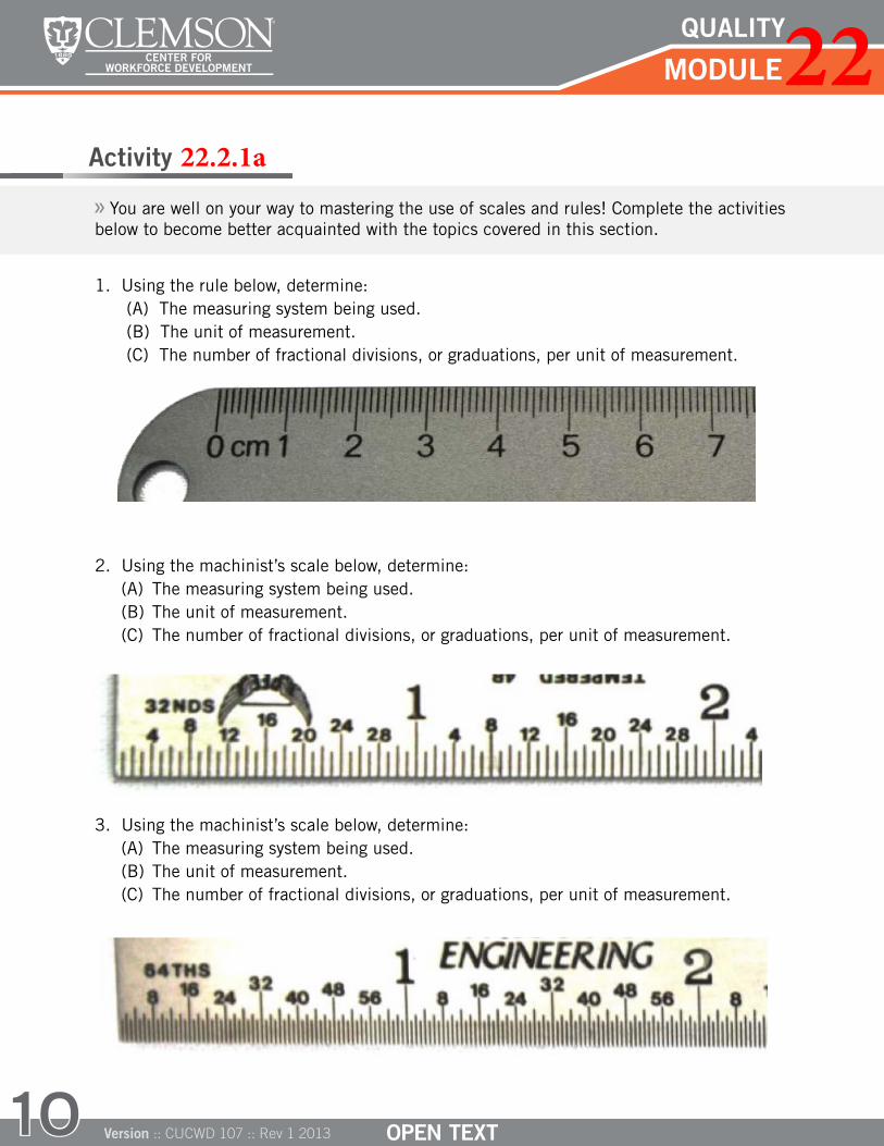
You are well on your way to mastering the use of scales and rules! Complete the activities below to become better acquainted with the topics covered in this section.
1. Using the rule below, determine:(A) The measuring system being used.(B) The unit of measurement.(C) The number of fractional divisions, or graduations, per unit of measurement.
2. Using the machinist’s scale below, determine:(A) The measuring system being used.(B) The unit of measurement.(C) The number of fractional divisions, or graduations, per unit of measurement.
3. Using the machinist’s scale below, determine:(A) The measuring system being used.(B) The unit of measurement.(C) The number of fractional divisions, or graduations, per unit of measurement.

QUALITY22CENTER FOR WORKFORCE DEVELOPMENT
Version :: CUCWD 107 :: Rev 1 2013 11
Activity 22.2.1b
A
B
C
Measure the length of each of the following objects.
B CA1.
A
B
C
2.
B CA
Activity 22.2.1c Report the measurement reading on each image as accurately as possible. Then respond
True or False to the statement below the image.
1.
2.
Measurement: This measurement is very precise. True or False
Measurement: This measurement is very precise. True or False

QUALITY22CENTER FOR WORKFORCE DEVELOPMENT
Version :: CUCWD 107 :: Rev 1 2013
The vernier scale, invented by French mathematician Pierre Vernier in 1631, is used as a vi-sual method of subdividing the smallest divisions on a scale for more precise measurements. All vernier instruments have two scales: the main scale and the vernier scale both of which have English and metric units. The vernier scale is a sliding secondary piece which is more finely graduated than the main scale, thus allowing for increased accuracy of reading. Figure 8 shows an example of the main scale and vernier scale on a caliper.
Figure 8. A vernier caliper with main scale and vernier scale.
Each inch on the main scale is divided into 10 parts, or tenths. Each tenth is further divided into halves, or twentieths, and then halves again into fortieths. On the vernier scale, each fortieth is further divided by 25, thus giving the ability of being precise up 1/1000 (0.001, one thousandths) of an inch.
Similarly for the metric system, on the main scale, each centimeter is divided into 10 parts, or tenths. On the vernier scale, each tenths is divided by 20, thus giving the ability of being precise up the 1/200 (0.005, 5 thousandths) of a centimeter or 1/20 (0.05, 5 hundredths) of a millimeter.
22.3.1 READING A VERNIER SCALE
Understanding how to read a vernier scale will help you in using both a venier caliper and a vernier micrometer, two common precision measuring tools. Other precision measuring tools that utilize the vernier scale include the vernier protractor and various surveying devices. Below are the six steps that experts follow when reading a vernier scale, using Figure 9 on the next page as an example.
12
22.3 The Vernier Scale
Vernier ScaleMain Scale
top scale is in centimeters bottom scale is in inches
Close-up of a vernier caliper

QUALITY22CENTER FOR WORKFORCE DEVELOPMENT
Version :: CUCWD 107 :: Rev 1 2013 13
Figure 9. Read the measurement on the vernier scale above in inches
STEP 1: Determine the measuring system and unit of measurement you are using
It is important to get into the habit of knowing what measuring system you want to use and that is shown on your instrument. In Figure 9, the measuring system used is the English system and the unit of measurement is 1 inch. This was determined by the marking on the lower right hand corner of the scales which reads 1/1000” or 1/1000th of an inch.
STEP 2: Find the major reading
The major reading is found on the main scale, and it corresponds to the smallest of the two unit measures on which the zero of the vernier scale lies. In Figure 9, the vernier scale lies between 0 and 1 in. Therefore, the major reading is 0.000 in.
STEP 3: Find the minor reading
The minor reading is also found on the main scale. It corresponds to the smallest of the two tenth measures on which the zero of the vernier scale lies. In Figure 9, the vernier scale lies between 8 and 9. Therefore, the minor reading holds the first decimal place and is 0.800 in.
STEP 4: Find the sub-minor reading
The sub-minor reading, also on the main scale, is found by counting the graduations after the minor graduation, but before the zero of the vernier scale, and then multiplying by 0.025 in. In Figure 9, there is only one graduation between the 0.800 and the vernier zero. Therefore, the sub-minor reading is 1 x 0.025 in. = 0.025 in.
STEP 5: Find the vernier reading
The vernier reading is the only reading found on the vernier scale. It is found by determining which of the 25 graduations on it aligns perfectly with a graduation on the main scale. In Figure 9, the 8th graduation on the vernier scale perfectly aligns with a graduation on the main scale. Therefore, the vernier reading holds the third decimal place and is 0.008 in.

QUALITY22CENTER FOR WORKFORCE DEVELOPMENT
Version :: CUCWD 107 :: Rev 1 201314
STEP 6: Add all readings together
The purpose of the major, minor, sub-minor, and vernier readings is to deconstruct the measure-ment. In order to obtain the precise measurement, add all of the readings together.
The equation below shows the addition of all the readings for Figure 9.
0.000 in ("major") + 0.800 in ("minor") + 0.025 in ("sub-minor") + 0.008 in ("vernier") = 0.833 in
PRACTICAL EXERCISE 22.3.1 Let’s read the measurement of Figure 10 using the six step process explained above.
Figure 10. Read the measurement on the vernier scale above in centimeters
STEP 1: What is the measurement system and unit of measurement depicted? Figure 10 is using the metric system, and the unit of measurement is 1 centimeter.
STEP 2: What is the major reading? The vernier zero lies between 2 cm and 3 cm. There-fore, the major reading is 2.000 cm.
STEP 3: What is the minor reading? The vernier zero lies between the 0.100 cm and 0.200 cm graduation. Therefore, the minor reading and the first decimal place is 0.100 cm.
STEP 4: What is the sub-minor reading? In Figure 10, there is no sub-minor reading be-cause the main scale is not sub-divided beyond tenths; therefore, we may continue to the vernier reading.
STEP 5: What is the vernier reading? The vernier reading that aligns with the main scale is the third graduation after the vernier zero. Since each graduation equals 0.005 cm, the vernier reading is 3 x 0.005 cm = 0.015 cm.
STEP 6: Now that we have all readings, let’s add them: 2.000 cm ("major") + 0.100 cm ("minor" ) + 0.015 cm ("vernier") = 2.115 cm
Figure 10 shows a reading of 2.115 cm.

QUALITY22CENTER FOR WORKFORCE DEVELOPMENT
Version :: CUCWD 107 :: Rev 1 2013 15
Activity 22.3.1
Find the measuring system, the unit of measure, and the major, minor, sub-minor (if applicable) and vernier readings on each of the following vernier scales. Then, add all the readings to obtain the measurement.
1.
Total Measurement:
Measurement System
Unit of Measurement
Major Reading
Minor Reading
Sub-minor Reading
Vernier Reading
2.
Total Measurement:
Measurement System
Unit of Measurement
Major Reading
Minor Reading
Sub-minor Reading
Vernier Reading
QUALITY22CENTER FOR WORKFORCE DEVELOPMENT
Version :: CUCWD 107 :: Rev 1 2013
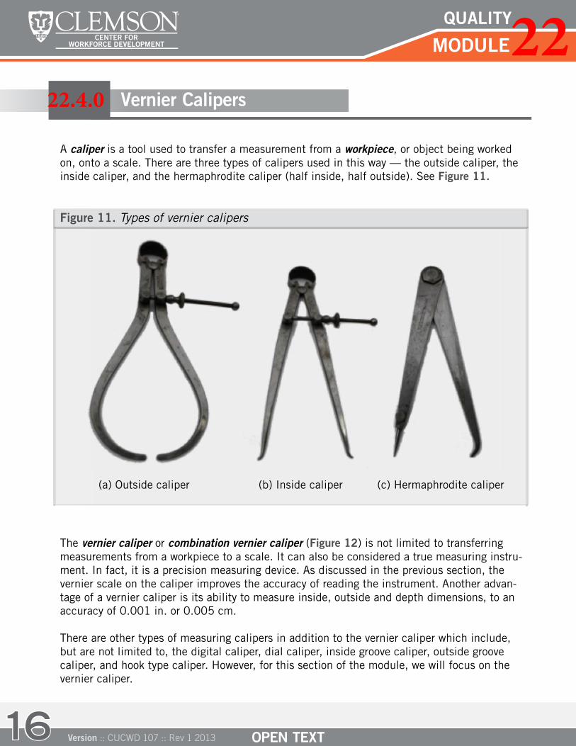
A caliper is a tool used to transfer a measurement from a workpiece, or object being worked on, onto a scale. There are three types of calipers used in this way — the outside caliper, the inside caliper, and the hermaphrodite caliper (half inside, half outside). See Figure 11.
Figure 11. Types of vernier calipers
16
22.4.0 Vernier Calipers
(a) Outside caliper (b) Inside caliper (c) Hermaphrodite caliper
The vernier caliper or combination vernier caliper (Figure 12) is not limited to transferring measurements from a workpiece to a scale. It can also be considered a true measuring instru-ment. In fact, it is a precision measuring device. As discussed in the previous section, the vernier scale on the caliper improves the accuracy of reading the instrument. Another advan-tage of a vernier caliper is its ability to measure inside, outside and depth dimensions, to an accuracy of 0.001 in. or 0.005 cm.
There are other types of measuring calipers in addition to the vernier caliper which include, but are not limited to, the digital caliper, dial caliper, inside groove caliper, outside groove caliper, and hook type caliper. However, for this section of the module, we will focus on the vernier caliper.

QUALITY22CENTER FOR WORKFORCE DEVELOPMENT
Version :: CUCWD 107 :: Rev 1 2013 17
22.4.1 HOW TO USE A VERNIER CALIPER
Before we learn how to use a vernier caliper, it is important to know its parts. The vernier caliper has eight major parts, as shown in Figure 13.
Figure 13. Eight major parts of a caliper
(1) The outside jaws used to measure the external dimensions of objects(2) The inside jaws used to measure the internal dimensions of objects(3) Vernier scale in inches(4) Locking screw used to lock movable parts in place for more accurate measurement(5) Main scale in centimeters(6) The depth probe used to measure the depth dimensions of objects(7) Main scale in inches(8) Vernier scale in centimeters
Vernier ScaleMain Scale
Figure 12. A vernier caliper or combination vernier caliper
4
8 7
5
6
1
2 3

QUALITY22CENTER FOR WORKFORCE DEVELOPMENT
Version :: CUCWD 107 :: Rev 1 2013
There are three types of measurements that can be taken using a vernier caliper — inside, outside and depth measurements. These are shown below in Figure 14.
Figure 14. Types of measurements using the vernier caliper
18
Examples of inside, outside and depth measurements
22.4.2 MEASUREMENT STEPS FOR VERNIER CALIPERS
Now that we know the parts and the capability of the venier caliper, let’s discuss how to use it appropriately. The follow will give you expert guidelines on the use of a vernier caliper:
Step 1: Ensure that the locking screw is looseStep 2: Close the jaws of the caliper to ensure the measurement of zero on the scaleStep 3: Slide the movable jaws to approximate the measurementStep 4: Bring the jaws into correct light contactStep 5: Tighten the clamp screwStep 6: Read the measurement as explained in the previous section.
Tips to Successful Measurements
When using a vernier caliper, there are certain tips to keep in mind: Always keep the instrument in proper alignment with the work Set the jaws exactly on the line of measurement Bring the jaws into contact with the workpiece, but do not add too much pressure Check the calibration of your caliper frequently
inside measurement
outside measurement
depth measurement

QUALITY22CENTER FOR WORKFORCE DEVELOPMENT
Version :: CUCWD 107 :: Rev 1 2013 19
Activity 22.4.2
C D
FE
A B
Match the names from the list below with the appropriate part of the vernier caliper. Word Bank
Outside jawsInside jawsDepth probe
Main scaleVernier scaleLocking Screw
The micrometer, used for precise measurements of length, is today’s most widely used precision measuring tool. Micrometers are more widely used than vernier calipers because of their more easily readable scales; as a result, they produce fewer reading errors, and, with a vernier scale, can measure precisely up to ten-thousandths of an inch (1/10000 in. or 0.0001 in.) or ten-thousandths of a centimeter (1/10000 cm or 0.0001 cm). This sec-tion will focus on the parts of the micrometer, the types of micrometers, using a microm-eter, and reading a micrometer.
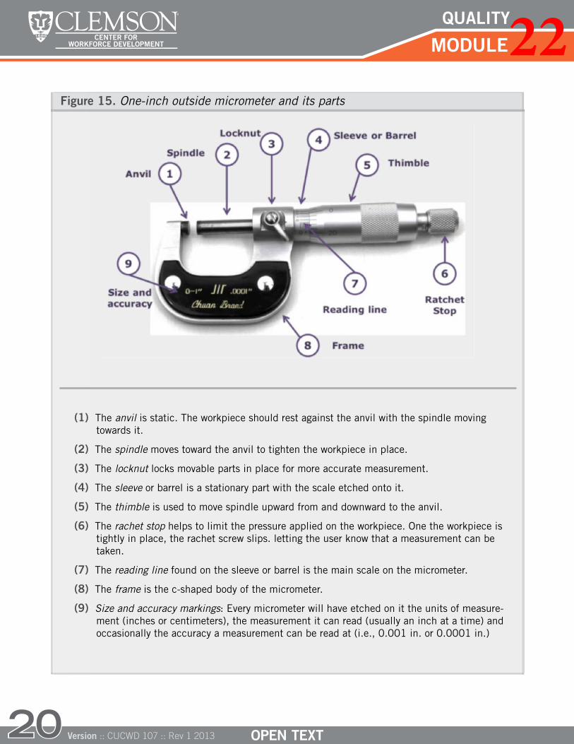
To obtain exact measurements, it is important to the know the parts of the micrometer as well as proper placing techniques of the object being measured. Figure 15 shows the nine major parts of a 1-in. micrometer and describes proper use of each part.
22.5 Micrometers
A
B
C
D
E
F
QUALITY22CENTER FOR WORKFORCE DEVELOPMENT
Version :: CUCWD 107 :: Rev 1 2013
(1) The anvil is static. The workpiece should rest against the anvil with the spindle movingtowards it.
(2) The spindle moves toward the anvil to tighten the workpiece in place.
(3) The locknut locks movable parts in place for more accurate measurement.
(4) The sleeve or barrel is a stationary part with the scale etched onto it.
(5) The thimble is used to move spindle upward from and downward to the anvil.
(6) The rachet stop helps to limit the pressure applied on the workpiece. One the workpiece istightly in place, the rachet screw slips. letting the user know that a measurement can betaken.
(7) The reading line found on the sleeve or barrel is the main scale on the micrometer.
(8) The frame is the c-shaped body of the micrometer.
(9) Size and accuracy markings: Every micrometer will have etched on it the units of measure- ment (inches or centimeters), the measurement it can read (usually an inch at a time) and occasionally the accuracy a measurement can be read at (i.e., 0.001 in. or 0.0001 in.)
20
Figure 15. One-inch outside micrometer and its parts

QUALITY22CENTER FOR WORKFORCE DEVELOPMENT
Version :: CUCWD 107 :: Rev 1 2013 21
22.5.1 TYPES OF MICROMETERS
There are three basic types of micrometers — the inside, the outside and the depth microm-eter — as seen in Figure 16. All of these micrometers are read the same way, but each one is specialized for the type of dimension measurement needed.
Figure 16. An inside (a), outside (b) and depth (c) micrometer
Micrometers also come in different sizes, but they can only truly measure up to an inch. For example, a 4-to-5 inch micrometer will open up to 5 inches, but can only be used to deter-mine with precision a measurement between 4 in. and 5 in. Figure 17 shows 3 different size micrometers: a 0 – 1 in. micrometer, a 4 in. – 5 in. micrometer, and a 7 in. – 8 in. microme-ter. As you can see, the size of the sleeve is exactly the same in all three because each mea-sures only up to an inch.
Figure 17. Examples of three sizes of micrometers
From top to bottom:
0 – 1 in. micrometer
4 in. – 5 in. micrometer,
7 in. – 8 in. micrometer
A
B
C

QUALITY22CENTER FOR WORKFORCE DEVELOPMENT
Version :: CUCWD 107 :: Rev 1 2013
0.100 inch marks
0.025 inch marks
0.001 inch marks
22.5.2 USING A MICROMETER
Using a micrometer has become a necessary task in every type of industry. Following the steps below will help you master the using the micrometer. If needed, you can look back to Figure 15 for a description of the parts of a micrometer.
22
STEP 1: Be sure that the locknut is loose
STEP 2: Close the spindle to ensure a measurement of zero on the scale.
STEP 3: Open the spindle.
STEP 4: Hold the micrometer (except for larger sizes) in your right hand with your little finger pressing the frame against the palm. The fourth finger will be placed just above the locknut. You will use your thumb and index finger to turn the thimble. The middle finger will be used intermittently for support. Hold the workpiece in your left hand and place it between the anvil and the spindle. Turn the thimble with the sleeve until contact is made.
STEP 5: When contact is made, turn the ratchet stop. When the proper pressure is reached, the ratchet will turn without moving the spindle.
STEP 6: Tighten the locknut.
STEP 7: Read the measurement as discussed in the next section.
22.5.3 READING A MICROMETER
Reading a micrometer is similar to reading a vernier caliper. Referring to the English 1-inch depth micrometer in Figure 18, each large graduation on a micrometer sleeve scale corre-sponds to the first decimal place or 0.100 in. This is then divided by four, making the next graduation markings on the micrometer sleeve scale correspond to 0.025 in. The scale on the thimble has 25 graduations, each of those correspond to the third decimal place or 0.001 in.
Figure 18. Read the measurement on this 1-in. depth micrometer.

QUALITY22CENTER FOR WORKFORCE DEVELOPMENT
Version :: CUCWD 107 :: Rev 1 2013
To get started, let’s look at an example illustrated in Figure 18. First, we identify that we are reading a measurement from a 1-in. depth micrometer. Because of this, the measure-ment we obtain must be less than 1 inch. This means that our first reading is 0.000 in. Next, we look to the large divisions on the sleeve. We know that the each large division is 0.100 in, and from the scale we see that the smallest visible number is 6. Therefore, the we obtain a reading of 0.600 in for the large barrel division. Since there are no visible 0.025 in. graduations after the large division, the small barrel division reading is 0 x 0.025 = 0.000 in. Lastly, we obtain the final reading from the thimble scale. Each graduation on the thimble scale is 0.001 in. Noticing that the thimble reading is right at 7, we can con-clude that the last reading is 7 x 0.001 in. = 0.007 in. Adding all of these readings, we can state that the final measurement is 0.607 inches.
0.000 in. + 0.600 in. + 0.000 in. + 0.007 in. = 0.607 in.
Now, let’s look at the example of the inside 3 in. – 4 in. micrometer measurement in Figure 19. The micrometer is measuring an object between 3 in. and 4 in., so our measurementshould lie between those two numbers. By looking at the picture, we can see that the mea-surement will be less than 4 in. Thus, our first reading is 3.000 in.
Now let’s look at the large divisions (0.100 in. each). From the scale, we see that the smallest visible number is 2. So, the second reading and first decimal place we have is 0.200 in. There are no visible 0.025 in. graduations after the large division. Thus the next reading is 0 x 0.025 = 0.000 in. The final reading is obtained from the thimble scale. Each graduation in the thimble scale is 0.001 in. Since thimble reading is right at 0, the last reading is 0.000 in. Adding these four readings, the measurement is as follows:
3.000 in. + 0.200 in. + 0.000 in. + 0.000 in. = 3.200 in.
3-4 inchmicrometer
Large barrel division
Small barrel division
Thimble scale
Final measurement
23
1-inchmicrometer
Large barrel division
Small barrel division
Thimble scale
Final measurement
Figure 19. Read the measurement on this 3 in. – 4 in. depth micrometer.
QUALITY22CENTER FOR WORKFORCE DEVELOPMENT
24
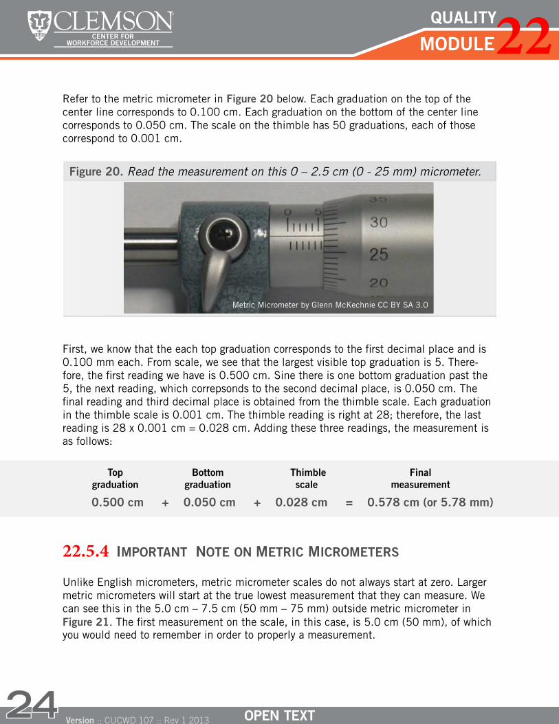
Refer to the metric micrometer in Figure 20 below. Each graduation on the top of the center line corresponds to 0.100 cm. Each graduation on the bottom of the center line corresponds to 0.050 cm. The scale on the thimble has 50 graduations, each of those correspond to 0.001 cm.
First, we know that the each top graduation corresponds to the first decimal place and is 0.100 mm each. From scale, we see that the largest visible top graduation is 5. There-fore, the first reading we have is 0.500 cm. Sine there is one bottom graduation past the 5, the next reading, which correpsonds to the second decimal place, is 0.050 cm. The final reading and third decimal place is obtained from the thimble scale. Each graduation in the thimble scale is 0.001 cm. The thimble reading is right at 28; therefore, the last reading is 28 x 0.001 cm = 0.028 cm. Adding these three readings, the measurement is as follows:
0.500 cm + 0.050 cm + 0.028 cm = 0.578 cm (or 5.78 mm)
22.5.4 IMPORTANT NOTE ON METRIC MICROMETERS
Unlike English micrometers, metric micrometer scales do not always start at zero. Larger metric micrometers will start at the true lowest measurement that they can measure. We can see this in the 5.0 cm – 7.5 cm (50 mm – 75 mm) outside metric micrometer in Figure 21. The first measurement on the scale, in this case, is 5.0 cm (50 mm), of which you would need to remember in order to properly a measurement.
Version :: CUCWD 107 :: Rev 1 2013
Figure 20. Read the measurement on this 0 – 2.5 cm (0 - 25 mm) micrometer.
Top graduation
Bottomgraduation
Thimble scale
Final measurement
Metric Micrometer by Glenn McKechnie CC BY SA 3.0

QUALITY22CENTER FOR WORKFORCE DEVELOPMENT
Version :: CUCWD 107 :: Rev 1 2013 25
Figure 21. The 5.0 cm – 7.5 cm (50 mm – 75 mm) outside metric micrometer
First graduation is 50 mm
Fotothek Mikrometer by Deutsche Fotothek CC BY SA 3.0
22.5.5 READING A VERNIER SCALE
Some micrometers have a vernier scale on the sleeve. These micrometers are the most precise of all tools presented in this module and can measure accurately to ten-thousandths of an inch (1/10000 in. or 0.0001 in.) or ten-thousandths of a centimeter (1/10000 cm or 0.0001 cm). The vernier scale on both the English and metric micrometer will have ten graduations. The reading provided on the vernier scale is the fourth decimal of the total reading. Therefore, each graduation of the vernier scale represents 0.0001 in. and the ver-nier scale reading corresponds to the alignment of the graduation on the thimble scale.
On the next page, we go through the steps to read the measurement of the 1 inch metric micrometer illustrated in Figure 22.
Figure 22. Example of a 1 in. outside micrometer.

QUALITY22CENTER FOR WORKFORCE DEVELOPMENT
Version :: CUCWD 107 :: Rev 1 2013
First, we know that each large division is 0.100 in. From the scale on the sleeve, we see that the largest visible number is 3. Therefore, the first reading we have is 0.300 in. Also, given that there are visible are three 0.025 in. graduations after the large division of the sleeve, the next reading is 3 x 0.025 = 0.075 in. Now on the thimble scale, recall that each graduation on the thimble scale is 0.001 in. Since the thimble reading is right at 16, the reading and third decimal place is 16 x 0.001 in. Lastly, we need to read from the vernier scale. Here, the thimble scale and the vernier scale align perfectly at zero, which makes the last reading and forth decimal place is 0 x 0.0001 in. Adding these four readings, the measurement is as follows:
0.300 in + 0.075 in + 0.016 in + 0.000 in = 0.391 in
Now, let’s look at the example of the 7 in. – 8 in. outside micrometer in Figure 23. This micrometer is measuring an object between 7 in. and 8 in. This means our measurement should be between 7 and 8 inches.
By looking at the picture, we can see that only a portion of the sleeve scale is shown and measurement will be less than 8 in. So we can determine that our first reading is 7.000 in. Let’s look now at the large divisions (0.100 in. each). From the scale, we see that the largest visible number is 4, making the second reading and first decimal place we have is 0.400 in. After the 4 on the large scale there are two visible 0.025 in. graduations. Thus we can determine that the next reading is 2 x 0.025 = 0.050 in. For the thimble scale reading, each graduation in the thimble scale is 0.001 in. we see that the thimble scale aligned with the vernier zero is between the 20 and 21 graduation. Therefore, the reading is 20 x 0.001 in. = 0.020 in. Finally, the last reading is obtained from the vernier scale.
26
Large barrel division
Small barrel division
Thimble scale
Vernierscale
Final measurement
Figure 23. Example of a 7 to 8 inch outside micrometer.

QUALITY22CENTER FOR WORKFORCE DEVELOPMENT
Version :: CUCWD 107 :: Rev 1 2013 27
The thimble scale and the vernier scale align perfectly at the 3 which makes the last read-ing and fourth decimal place 3 x 0.0001 in. = 0.0003 in. Adding these readings, the measurement is as follows:
7.000 in. + 0.400 in. + 0.050 in. + 0.020 in. + 0.0003 in. = 7.473 in.
Now, let’s read the measurement illustrated in Figure 24. First, we know that the each large graduation on the sleeve is 0.100 cm each. From sleeve scale, we see that the largest visible top graduation is 5; therefore, the first reading we have is 0.500 cm. There is one small graduation on the sleeve scale which corresponds to 0.050 cm; therefore, the next reading is 0.050 cm. The next reading is obtained from the thimble scale. Each graduation in the thimble scale is 0.001 cm. The thimble reading is right above 28; therefore, the thimble reading is 28 x 0.001 cm = 0.028 cm. The last reading comes from the vernier scale. The thimble scale and the vernier scale align best at the 3 graduation on the vernier; therefore, the last reading is 3 x 0.0001 cm = 0.0003 cm. Adding these four readings, the measurement is as follows:
0.500 cm + 0.050 cm + 0.028 cm + 0.0003 cm = 0.5783 cm or 5.783 mm
You are well on your way to becoming an expert in precision measuring using micrometers! The following activities will help solidify your knowledge in this area.
7-8 in.micrometer
Large barrel division
Small barreldivision
Thimble scale
Final measurement
Vernierscale
Figure 24. Example of a 0 to 2.5 cm (25mm) metric vernier micrometer
Large graduation
Smallgraduation
Thimble scale
Vernierscale
Final measurement

QUALITY22CENTER FOR WORKFORCE DEVELOPMENT
Version :: CUCWD 107 :: Rev 1 201328
Activity 22.5.5
1. Read the measurement on this 1-in. outside micrometer.
Measurement above 1 in.:
Large barrel division:
Small barrel division:
Thimble division:
Vernier reading:
Total: Micrometer by Glenn McKechnie CC BY SA 2.0
Inside Micrometer by Glenn McKechnie CC BY SA 3.0
2. Read the measurement on this 0.5 cm – 3.0 cm (5 mm – 30 mm) inside micrometer.
Large barrel division:
Small barrel division:
Thimble division:
Vernier reading:
Total:
3. Read the measurement on this 1-in. outside micrometer.
Measurement above 1 in.:
Large barrel division:
Small barrel division:
Thimble division:
Vernier reading:
Total:
Measurement above 1 in.:
Large barrel division:
Small barrel division:
Thimble division:
Vernier reading:
Total:
4. Read the measurement on this 1in. – 2 in. outside micrometer.

QUALITY22CENTER FOR WORKFORCE DEVELOPMENT
Version :: CUCWD 107 :: Rev 1 2013 29
• Height gauge• Telescoping gauge• Disc micrometer
• Dial bore gauge• Protractors• Dial indicators
22.1 Precision measuring tools pg.1
22.2 Machinist’s scale pg.3 Metric scale pg.3 Graduation pg.4 Numerator pg.8
22.2 Denominator pg.8 Factors pg.8 Common factor pg.8 Greatest common
factor pg.8
22.3 Vernier scale pg.12
22.4 Caliper pg.16 Workpiece pg.16 Vernier caliper pg.16
22.5 Micrometer pg.19
Key Concepts
Despite differences in precision, the scale, vernier scale, vernier caliper and micrometer can all be used for linear measurements.
Accurate readings depend not only on the machinist’s perception but also on tool related skills such as the selection of the proper tool and the calibration process.
The vernier scale is a common appendix which increases the precision in measurements. Consequently, it is important that the student master vernier readings. This skill will come in handy for obtaining accurate measurements using the vernier caliper and the micrometer.
The vernier caliper is a versatile tool, and it is the only instrument presented here which can be used for precise measurements of inside, outside and depth dimensions.
Reading the vernier micrometer involves the most complex process as this instrument uses three scales (thimble, sleeve, and vernier) to provide a measurement. However, this instrument is also the most precise of all tools presented in this module.
Key Terms
Further Study
1. The Coordinate Metrology Society’s objective is to expand and promote the usage of mobile metrologysystems. Visit their website at www.cmsc.org to view their journal publications and articles on precisionmetrology.
2. This module discussed some of the most common precision measuring instruments. Use the internet toresearch the following precision measuring tools and to learn what they measure:

QUALITY22CENTER FOR WORKFORCE DEVELOPMENT
Version :: CUCWD 107 :: Rev 1 201330
Caliper: A tool used to transfer a measurement from a workpiece to a scale
Common factor: A factor that is common between two or more numbers
Denominator: The bottom number in a fraction
Factors: Numbers multiplied together to obtain a third number
Graduation or mark: The fractional division between a unit of measurement
Greatest common factor: The largest common number that is a factor of both the numerator and denominator
Machinist’s scale or steel rule: A 6-in rule that is the most common and simplest linear measuring instrument found in a machine shop
Metric scale: A scale based on the units of the metric system
Micrometer: A precision measuring tool having the capability to measure accurately up to 0.0001 in. (ten-thousandths of an inch)
Numerator: The top number in a fraction
Precision measuring tools: Tools designed for taking precise and accurate measurements
Vernier caliper: A precision measuring tool that combines a caliper and a scale to take measurements
Vernier scale: Is a scale that is combined with a main scaled and is used as a visual method of subdividing the smallest division on a main scale to make more precise measurements. Invented by Pierre Vernier in 1631
Workpiece: An object being worked on with a tool
This material is based upon work supported by the National Science Foundation under Grant Number DUE-1104181. Any opinions, findings, and conclusions or recommendations expressed in this material are those of the author(s) and do not necessarily reflect the views of the National Science Foundation.
Copyright © 2013 Clemson University Center for Workforce Development. All Rights Reserved.

QUALITY11CENTER FOR WORKFORCE DEVELOPMENT
Version :: CUCWD 101 :: Rev 1 2012Version :: CUCWD 107 :: Rev 1 2013
Attribution Table
QUALITY11OPEN TEXTPlacement Author(s) Title Source License
Figure1a
MicrosoftMan working on some home improvements
measuring with a rulerMicrosoft: searched for ‘ruler’ unknown
Figure 1b
USDArobotic laser aligned
device
http://www.flickr.com/photos/usdagov/6060432502/in/
photostream/CC BY 2.0
Figure 2a-d
Taken by CUCWD/In image folder (a) Machinist’sScale.jpg (b) TapeRule.jpg (c)Architect’sScale.jpg (d) Engineer’sScale.jpg
Table 1 Taken by CUCWD/In image folder CentimeterScale.jpg & InchesScale.jpg
Figure 3a,b
Taken by CUCWD/In image folder (a) Alignedwithwork.jpg (b) Notalignedwithwork.jpg
Figure4,5
Taken by CUCWD/In image folder CentimeterNoBackground.png
Figure6,7
Taken by CUCWD/In image folder InchesNoBackground.png
Activity 11.2.1
Taken by CUCWD/In image folder 1) CentimeterScale.jpg2) Machinist’sScale.jpg3) Machinist’sScale.jpg
Activity 11.2.2
Taken by CUCWD/In image folder 1) CentimeterNoBackground.png2) Machinist’sScale.jpg
Activity 11.2.3
Taken by CUCWD/In image folder 1) InchesNoBackground.png2) Machinist’sScale.jpg
Figure8,9
Taken by CUCWD/In image folderVernierCaliper.jpg
Figure10
Taken by CUCWD/In image folderVernierExample1.jpg
Activity 11.3.1
Taken by CUCWD/In image folder1)VernierScaleActivity.jpg --> the inches section2)VernierScaleActivity.jpg --> the cm section
Figure11
Taken by CUCWD/In image folderCalipers.jpg & Calipers.psd
Figure12
Taken by CUCWD/In image folderVernierCaliper.jpg
Figure13
Taken by CUCWD/In image folderOriginal without numbers --> VernierOpen.jpg --> VernierOpen.psdWith numbers (taken from powerpoint) --> LabeledCaliper.png

QUALITY11CENTER FOR WORKFORCE DEVELOPMENT
Version :: CUCWD 101 :: Rev 1 2012Version :: CUCWD 107 :: Rev 1 2013
Attribution Table
QUALITY11
Version :: CUCWD 107 :: Rev 1 2013
Attribution TableAttribution Table (continued)
Figure14
Taken by CUCWD/In image folderOriginal without figures --> VernierOpen.jpg --> VernierOpen.psdWith numbers (taken from powerpoint) --> CaliperWFigures.png
Activity 11.4.1
Taken by CUCWD/In image folderOriginal without figures --> VernierOpen.jpg --> VernierOpen.psdWith numbers (taken from powerpoint) --> LabeledCaliperActivity.png
Figure15
Taken by CUCWD/In image folderOriginal without figures --> OutsideMicrometer.jpgWith numbers (taken from powerpoint) --> LabeledMicrometer.png
Figure16
Taken by CUCWD/In image folder(a) InsideMicrometer.jpg(b) OutsideMicrometer.jpg(c) DepthMicrometer.jpg
Figure17
Taken by CUCWD/In image folderMicrometers.jpg
Figure18
Taken by CUCWD/In image folderInsideMicrometer.jpg (zoomed in)
Figure19
Taken by CUCWD/In image folderDepthMicrometer.jpg (zoomed in)
Figure20
Glenn McKenchnie
Metric Micrometerhttp://commons.wikimedia.org/wiki/File:578metric-mi-crometer.jpg
CC BY SA 2.0
Figure21
Deutsche Fotothek Fotothek Mikrometer
http://commons.wikimedia.org/wiki/File:Fotothek_df_n-18_0000164_Mikrometer-schraube.jpg
CC BY SA 3.0
Figure22
Taken by CUCWD/In image folderMicrometerExample1.jpg
Figure23
Taken by CUCWD/In image folderMicrometerExample2.jpg
Figure24
Glenn McKenchnie
Metric Micrometerhttp://commons.wikimedia.org/wiki/File:5783metric-micrometer.jpg
CC BY SA 3.0
Activity 2.5.1
1)Glenn Mckechnie Micrometer
http://commons.wikimedia.org/wiki/File:276inch-mi-
crometer.jpg
CC BY SA 2.0
Activity 11.5.1
2)
Glenn McKenchnie
Inside Micrometerhttp://commons.wi-kimedia.org/wiki/
CC BY SA 3.0
Activity 11.5.1 3),4)
Taken by CUCWD/In image folder2) MicrometerActivity2.jpg3) MicrometerActivity3.jpg

QUALITY11CENTER FOR WORKFORCE DEVELOPMENT
Version :: CUCWD 101 :: Rev 1 2012Version :: CUCWD 107 :: Rev 1 2013
Attribution Table
QUALITY11
Version :: CUCWD 107 :: Rev 1 2013
Attribution TableAttribution Table (continued)
ASSESSMENT GUIDE
Placement Author(s) Title Source License
Caliper Diagram
Taken by CUCWD/In image folderOriginal without figures --> VernierOpen.jpg & VernierOpen.psdWith numbers (taken from powerpoint) --> LabeledCaliperActivity.png
Micrometer Diagram
Taken by CUCWD/In image folderOriginal without figures --> OutsideMicrometer.jpgWith numbers (taken from powerpoint without labels) --> LabeledMicrometerAssessment.png
Micrometer Reading
Taken by CUCWD/In image folderMicrometerAssessment1.jpgMicrometerAssessment1.psd
Measurment Section
Taken by CUCWD/In image folder1. InchesNoBackground.png2. VernierScale.jpg (zoomed in)3. MicrometerAssessment2.jpg
POWERPOINT (only images that do not match with Open Text)
Slide # Author(s) Title Source License
7 Thomas Doerfer
BMW 325http://commons.wikimedia.org/wiki/File:Washauto06_
bmw_325_xi.jpgCC BY SA 2.5
7 Greg GoabelGeneral Electric
YJ93
http://commons.wikimedia.org/wiki/File:General_Electric_YJ93.
jpgCC BY SA 2.0
8 Taken by CUCWD/In image folderRuleSlide8.jpg
8 ZanMan Yard Stickhttp://commons.wikimedia.org/
wiki/File:YardStick.jpgCC BY SA 3.0
8 Za Meter Stickhttp://commons.wikimedia.org/wiki/File:Metre_pliant_500px.
pngCC BY SA 3.0
8 Taken by CUCWD/In image folderTapeRuleSlide8.jpg
70 Microsoft 00290924.wmf Microsoft: searched for ‘ruler’ unknown
70 Microsoft 00427821.jpgMicrosoft: searched for
‘microscope’unknown
70 Taken by CUCWD/In image folder --> VernierCaliper.jpg
71 Microsoft 00352217.wmf Microsoft: searched for ‘Caliper’ unknown
71 Microsoft00055081.wmf
rotatedMicrosoft: searched for
‘Micrometer’unknown

Version :: CUCWD 101 :: Rev 1 2012
Page intentionally left blank