quanta-flame replacement flame … flame 5004-m...the 5004-m-78 flame safeguard replacement chassis...
TRANSCRIPT

1Rev. 11/12/2009 Pre-Release
The 5004-M-78 flame safeguard replacement chassis is designed to be a direct replacement for the CB780 Cleaver Brooks and most Honeywell RM7800E and RM7800L series burner controls. The 5004-M-78 mounts directly into an existing Q7800A1005, Q7800B1003 or CB 780 (833-2725) wiring sub-base. Existing flame sensors and scanners can be reused or replaced with Preferred UV, IR or UV self-checking scanners. An auxiliary connector is used for interface with Modbus communication or to provide a remote reset function.
The 5004-M-78 controller is a state-of-the-art microcomputer based burner management system designed for a single burner boiler or process heat application. An LCD display provides real-time diagnostic and status messages for the operator. The 5004-M-78 accepts (up to two) any one of the 3 various sensors: FR,UV,IR.
Unlike other flame safeguard controllers that require a multitude of modules (programmers, flame amplifiers, purge times, etc.) the Preferred Quanta-Flame 5004-M-78 has just one processor with a built-in universal amplifier that accepts UV, UV self check scanner, IR scanner, and flame rod inputs.
PREFERRED InsTRUMEnTs 5004-M-78
QUAnTA-FLAME REPLACEMEnT FLAME sAFEgUARD ConTRoLREPLACEs CB780 AnD RM7800 FLAME sAFEgUARD ConTRoL MICRoPRoCEssoRs
product description
5004-M-78 CHAssIs
ApproVALs
Underwriters Laboratories, Inc.File number E233069???

2
tAbLe of contents
WArning
Before the 5004-M-78 control is installed as a replacement, the dipswitches and scanner jumper must be correctly configured to match the sequence and sensor type of the replaced control. Please refer to Installation, Configuration and Specification sections of this manual. No wiring changes to the control or existing connected compatible scanner is required. For a list of compatible sensors please refer to the Quanta-Flame 5004-M-78 Specifications section of this manual.
• Compatible to Cleaver Brooks model 780 and Honeywell 7800 controls & sensors• Local LCD display for status and troubleshooting• optional remote display (5004-216Rn)• sequence status lights • Jacks for direct flame strength measurement 0-5 VDC• Low profile• Plug-in sub-base (compatible to CB 833-2725 & HW Q7800A) • Field selectable by dipswitches- pre-purge time, response to a power failure, trial for
ignition time, check for trip interlock short and jumper selectable FR/IR/UV sensors.• Early spark termination• Pilot test mode• Burner modulation actuator sequencing• Rs 485 Modbus communication• Every unit interfaces to infrared, ultraviolet, ultraviolet self-check or flame rod sen-
sors. sensor specific plug-in amplifiers are not required.• Remote/local reset from lockout state• optional 16 point annunciator (QA16)
feAtures
features .......................................................................................................2Specifications ..............................................................................................3Terminal Ratings ........................................................................................3Accessory Selection ....................................................................................4Chassis Installation ....................................................................................6Flame Scanner Installation .......................................................................6Wiring ....................................................................................................... 11Programmer Set-up .................................................................................19Programmer Timing Sequence ...............................................................24Installation Testing ...................................................................................26Trouble-Shooting ......................................................................................28Digital Communication Setup .................................................................33Warranty and Returns ............................................................................39

3Rev. 11/12/2009 Pre-Release
Mechanical: 6.00L” by 5.00” W by 2.00” DWeight: 2 Lbsoperating Temperature: -40°F to +140°F (-40°C to +60°C) UV scanners -20°C to 60°C,Electrical: Voltage: 120 VAC +10% - 15%, 50/60 HzPower consumption: 2 VAFlame Failure Response Time: 2.5 to 3.5 secondsPurge Time: 30, 60, 90, 150, 180, 300, 450, or 900 seconds (dipswitch selectable)Pilot Trial for Ignition Time: 3, 5, or 10 seconds (dipswitch selectable)Flame sensor Inputs: UV, IR or FRCompatible Flame sensors: Flame Rod (s1-FR Jumper)Model 5004-01 Ultraviolet, nsC (s1-UV Jumper)Model 5002-01nC Ultraviolet, nsC (s1-UV Jumper)Model 5002-01 Ultraviolet, sC (s1-UV Jumper)Model 5002-11nC Infrared, (s1-IR Jumper)Model C7027A Ultraviolet, nsC-HW (s1-UV) Model 817-1743 Ultraviolet, nsC-CB (s1-UV Jumper)Model C7015A IR Honeywell (Jumper s1-IR)Model 817-1742 CB (Jumper s1-IR)
specificAtions
TerminalNumber Description Rating
3 Alarm Relay 2 Amps Resistive
5 Blower Relay 1/2 HP Inductive
8 Pilot Valves 10 Amps Resistive1/4 HP Inductive
9 Main Fuel Valves 10 Amps Resistive1/4 HP Inductive
10 IgnitionTransformer
10 Amps Resistive1/4 HP Inductive
12 – 15 ModulationTerminals 2 Amps Resistive
terMinAL rAtings
Total connected 120 VAC load must not exceed 15 Amps.

4
Display ModuleThe 5004-216 display module is included with the 5004-M-78 controller. It may be removed from the chassis without loss of functionality. optional remote display 5004-21Rn flush-mounts to an enclosure, is nEMA 4, and includes a 6’ cable and a plug-in terminal adaptor.
Flame ScannersThe scanner type to be used is selected by a jumper on back of the chassis. In addition to the Honeywell scanners detailed above, the 5004-M-78 is compatible with the following Preferred scanners.
Ultraviolet Model 5004-01C The UV sensor detects light emitted from the flame within the ultraviolet light spectrum. Includes the basic UV scanner and cable.
Infrared Model 5004-11C The IR sensor detects light emitted from the flame within the IR light spectrum. Includes the basic IR scanner and cable.
Ultraviolet self-Check Model 5002-01 The UV self-check sensor detects light emitted from the flame within the ultraviolet light spectrum. This sensor is intended for applications where the burner operates continuously (24 hours). The self-check scanner interrupts the UV light from the burner every ten seconds to verify the proper operation of the sensing element and the internal components.
Ultraviolet non self-Check Model 5002-01nC The UV sensor detects light emitted from the flame within the ultraviolet light spectrum. This sensor is intended for applications where a burner is cycled at least once every 24 hours.
Accessory seLection

5Rev. 11/12/2009 Pre-Release
Infrared Model 5002-11nC The IR sensor detects light emitted from the flame within the infrared light spectrum. This sensor detects fluctuations of flame intensity.
Flame Rod The flame rod works on the principle of flame rectification and senses a small direct current flowing through the flame between the flame rod and the burner ground.
WArning
The 5004-01C and 5002-01NC UV flame sensors are non-self checking UV detectors. These should only be applied to burners that cycle often in order to allow the control to perform a safety check on their operation. If the burner is not to be frequently cycled but run continuously, the 5002-01 self-checking UV, 5004-11C or the 5002-11NC infrared flame scanner must be used.

6
chAssis instALLAtion
Mounting the Control Chassis:The 5004-M-78 is fully compatible with Honeywell Q7800A1005, Q7800B1003, and Cleaver-Brooks 833-2725 wiring bases.
2.13
2.501 .62
3.635.00
6.00
AUXILIARY CONNECTOR
The scanner must be mounted so that it sights a point at the intersection of the main and pilot flames. For proper scanner sensing the following conditions must be present:
• A reliable and stable pilot flame.• A reliable and stable main flame.• The flame scanners must have an unobstructed view of the flame.
fLAMe scAnner instALLAtion
gooD FLAME sIgHTIng PooR FLAME sIgHTIng
7Rev. 11/12/2009 Pre-Release
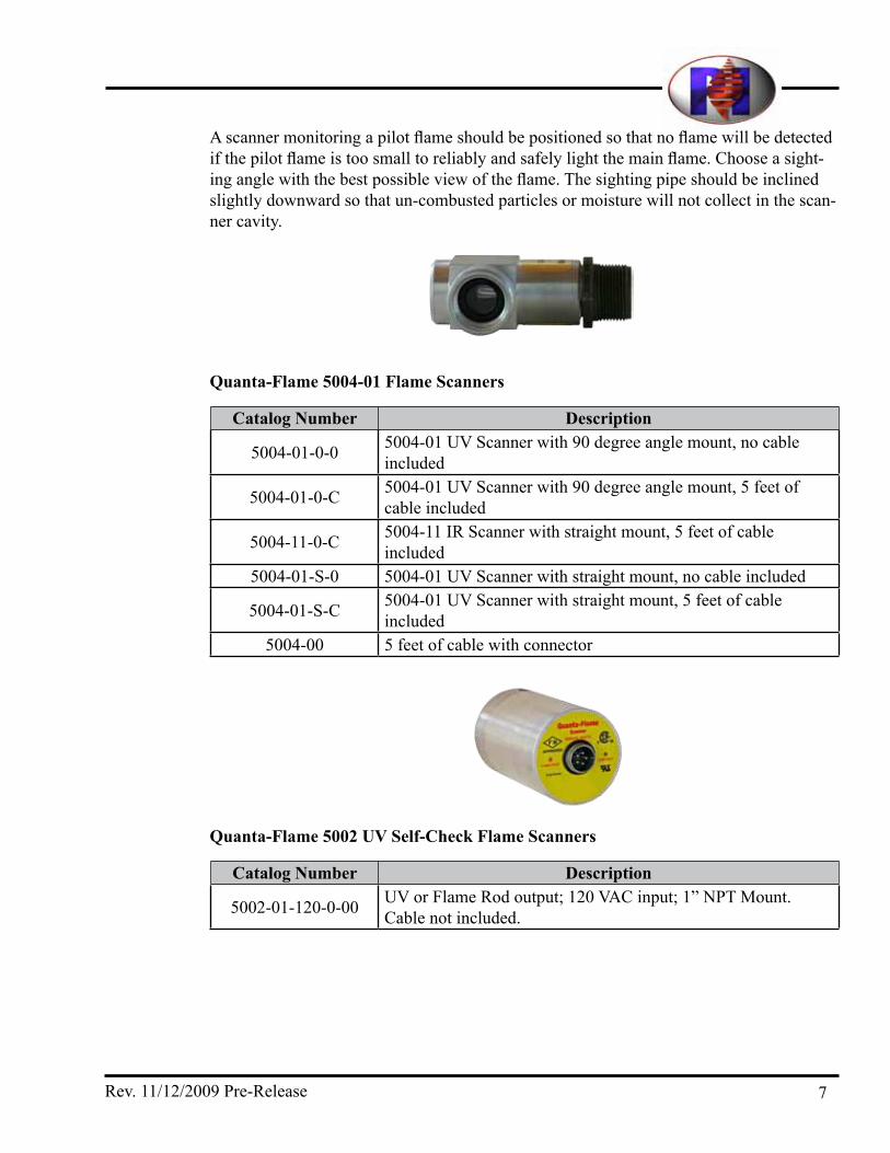
A scanner monitoring a pilot flame should be positioned so that no flame will be detected if the pilot flame is too small to reliably and safely light the main flame. Choose a sight-ing angle with the best possible view of the flame. The sighting pipe should be inclined slightly downward so that un-combusted particles or moisture will not collect in the scan-ner cavity.
Catalog Number Description
5004-01-0-0 5004-01 UV scanner with 90 degree angle mount, no cable included
5004-01-0-C 5004-01 UV scanner with 90 degree angle mount, 5 feet of cable included
5004-11-0-C 5004-11 IR scanner with straight mount, 5 feet of cable included
5004-01-s-0 5004-01 UV scanner with straight mount, no cable included
5004-01-s-C 5004-01 UV scanner with straight mount, 5 feet of cable included
5004-00 5 feet of cable with connector
Quanta-Flame 5004-01 Flame Scanners
Catalog Number Description
5002-01-120-0-00 UV or Flame Rod output; 120 VAC input; 1” nPT Mount. Cable not included.
Quanta-Flame 5002 UV Self-Check Flame Scanners

8
Catalog Number Description
5002-01-nC-120-R-00-00 Contact closure output only: ½” nPT. Aluminum alloy housing.
5002-01-nC-120-F-00-00 UV/Flame Rod signal only; ½” nPT. Aluminum alloy housing.
5002-01-nC-120-R-00-Hs Contact closure output only. High sensitivity; ½” nPT. Aluminum alloy housing.
5002-01-nC-120-F-00-Hs UV/Flame Rod signal only. High sensitivity; ½” nPT. Aluminum alloy housing.
Quanta-Flame 5002NC Non Self-Check Flame Scanners
Ultraviolet Flame Detectors (cable not included)
Catalog Number Description
5002-11-nC-120-R-00-00 Contact closure output only: ½” nPT. Aluminum alloy housing.
5002-11-nC-120-F-00-00 UV/Flame Rod signal only; ½” nPT. Aluminum alloy housing.
5002-11-nC-120-R-00-Hs Contact closure output only. High sensitivity; ½” nPT. Aluminum alloy housing.
5002-11-nC-120-F-00-Hs UV/Flame Rod signal only. High sensitivity; ½” nPT. Aluminum alloy housing.
Infrared Flame Detectors (cable not included)

9Rev. 11/12/2009 Pre-Release
Catalog Number Description5002-EP Heavy Duty scanner Housing
5002-EPss Heavy Duty scanner Housing-stainless steel5002-EPC 5000 & 5002 scanner series Terminal Connector5000-02-05 scanner Cable 5 feet – with connector5000-02-10 scanner Cable 10 feet – with connector
5000-02 scanner Cable – specify Length – connector not included. Price per foot
5002-02/91 Adapter for 5602-91-7 cable (from a 5602-91 scanner to the 5002-01)
-wt Water tight connector added to scanner Cable
Scanner Accessories
Catalog Number Description5000-01-00L Replacement quartz lens for mtg nipple 5000-01-00.
5000-73/74-ss swivel mount, 2" nPT x 1" nPTF, stainless steel.
5000-475 single piece nipple, 1" nPT x 4" long with quartz lens and purge connection.
5000-01-00-ss Mounting nipple for scanner - quartz lens, 1" nPT x 4" long. stainless steel.
5000-11-00-ss Mounting nipple for scanner - glass lens, 1" nPT x 4" long. stainless steel.
5000-01-00A Mounting nipple for scanner - insert quartz lens for higher pressure applications. stainless steel
5000-01-04-CT Mounting nipple for scanner- 1" threads, carbon Teflon for 450 ºF service. 1" nPT x 4" long.
Scanner Mounting Hardware

10
Catalog Number Description
7077-17-FP-0-200 Insulator with Flat Quartz Lens; no Purge connection; 200°F Rating
7077-17-FP-P-200 Insulator with Flat Quartz Lens; with Purge connection; 200°F Rating
7077-17-FP-0-450 Insulator with Flat Quartz Lens; no Purge connection; 450°F Rating
7077-17-FP-P-450 Insulator with Flat Quartz Lens; with Purge connection; 450°F Rating
7077-17-MP-0-200 Insulator with Magnifying Quartz Lens; no Purge connection; 200°F Rating
7077-17-MP-P-200 Insulator with Magnifying Quartz Lens; with Purge connection; 200°F Rating
7077-17-MP-0-450 Insulator with Magnifying Quartz Lens; no Purge connection; 450°F Rating
7077-17-MP-P-450 Insulator with Magnifying Quartz Lens; with Purge connection; 450°F Rating
Mounting Nipples & Lenses for 5004-01 ScannersThe following parts are used in applications to reduce the heat transfer effects upon the flame scanner. In addition some of these components include magnifying lenses to improve flame signal detection.
Catalog Number Description7077-17Pn-200 nipple, ½” nPT; with Purge connection; 200° F Rating7077-17En-200 nipple, ½” nPT; no Purge connection; 200° F Rating7077-17Pn-450 nipple, ½” nPT; with Purge connection; 450° F Rating7077-17En-450 nipple, ½” nPT; no Purge connection; 450° F Rating
Additional scanner nipples without quartz lenses:

11Rev. 11/12/2009 Pre-Release
WArning
Only qualified technicians with specific knowledge of the design of the burner and all applicable burner/boiler safety codes should install, configure and commission the 5004-M-78. Incorrect installation can result in equipment damage, injury, or death.
All system wiring must be run in accordance with the national Electrical Code and all local code requirements.• Always remove all power to the system before wiring.• Control transformer neutral must be grounded.• This product is designed to work in a variety of applications and conditions; however
some applications may not be applicable due to the presence of high electrical noise, lack of adequate ground connections, floating neutrals or other known or unknown conditions. It is therefore important to ensure proper system environment before installing these devices.
• Do not subject the controller to excessive vibration.• Flame sensor wiring must be run in a separate conduit, with no other wiring. Use
shielded cable, terminate shield as shown, and insulate all exposed shielding. Route sensor wiring a sufficient distance away from any type of ignition or other wiring to avoid electrical noise interference. Each sensor wiring must be run separate from all other wires including other sensors. In some cases shielded cable or coax may be required for long distances or high electrical interference environments. Each pair of sensor leads should be in their own shielded or coaxial pair and terminated at the control.
• All wire near hot surfaces should be rated for 90°C (195°F) or at least 25°C (50°F) higher than the surface temperature.
• Route the ignition transformer high voltage wire away from the flame sensor wiring and all other 120 VAC wiring. Use only automotive style noise-suppression ignition wire. Mount the ignition transformer as close to the igniter as practical. set spark gaps to the minimum setting. ground the ignition transformer to metal that is con-nected to the igniter. Use star washers to cut through the paint.
• Keep VsD motor wiring away from the flame sensor wiring and all other 120 VAC wiring. Run motor wires in rigid metal conduit, or in EMT conduit with conduct-ing compression fittings (set screw hub fittings not allowed), or use shielded motor power cable. Run a ground wire from the motor frame to the VsD frame in the same conduit as the motor wires. Also run a ground wire from the VsD frame to the power source ground.
• Wiring from the VsD output to the motor must be run in a dedicated conduit separate from other wiring including the 3-phase power supply. This conduit should contain only the (3) phase power wires and a ground wire. The ground wire is connected at
Wiring

12
the VsD frame to the motor.• Ensure a second ground wire is installed from the AC power source to the VsD frame for nEC
safety grounding.• output wiring from VsD cannot be run through junction boxes that include other wiring.• The VsD to motor conduit must be metal conduit and must have either threaded or non-insulating
compression fittings. PVC conduit, BX, greenfield or EMT set screw-style hubs connectors are not allowed.
• All DC signal wiring must be run in dedicated conduit and kept as far away from VsD to motor conduit as possible.
• AC power source to VsD must be run in dedicated conduit. Running AC supply to VsD and VsD to motor wiring in same conduit is not allowed.
• Cable shielding removed for wire termination should be kept to a minimum.• Cable shield and drain wires are properly insulated to prevent accidental connection to earth ground.• Provide a proper ground system to minimize the effects of line and other electrical quality issues.
A properly designed ground system must meet all the safety requirements so that any wiring or radiated voltage quality issues, such as spikes, surges and impulses have no effect on the control or system operation. A low impedance path to ground is required to ensure that any currents involved with any surge voltages will not adversely affect components in the system.
• The control system, being microprocessor based, requires a ground system that provides a zero-voltage reference. The voltage measured from L2 to all other terminals except L1 should be 0 volts.
• The most effective ground is to run the ground wire in the same raceway as the hot and neutral from the main distribution service panel (not intermediate sub-panels) to the burner control panel and insure that this ground wire is well bonded to the control panel.
• The earth ground wire must be capable of conducting the current to blow the 20A fuse in event of an internal short circuit. A number 14 AWg copper conductor is adequate, wide straps or brackets are preferred rather than lead wires.
• The ground path needs to be low impedance (less than 1 ohm) to the equipment frame, which in turn needs low impedance to earth ground. For a ground path to be low impedance at RF frequencies, the connection must be made with minimum length conductors having maximum surface areas.
• All connections should be free of nonconductive coatings and protected against rust.• Utilizing conduit as a means of providing a ground must be avoided.• Installing ground rods at the burner control panel defeats the purpose of a single point ground as
described above and could also present a safety hazard.• Rs485 wiring should not be run in conduits with 120 VAC wiring.

13Rev. 11/12/2009 Pre-Release
GN3456789
F
1213141516171819202122
10
FR
IR UVSCANNER INPUT (LOW)
120 VAC (NEUTRAL)
ALARM (120 VAC)
120 VAC (HOT)
F.D. FAN MOTOR
START (RECYCLE) LIMITS
NON-RECYCLE INTERLOCKS
PILOT VALVES
MAIN FUEL VALVES
IGNITION TRANSFORMER
SCANNER INPUT (HIGH)INDEX TABS
PURGE
COMMON
LOW FIRE
MODULATION
NOT USED
REMOTE RESET
LOW FIRE SWITCH
PURGE SWITCH
POVC INPUT
15 SEC MTFI
NOT USED
5004-M-78 TERMInAL LAyoUT

14
19
18 Burner Modulation
Wiring
Low Fire / Ignition
High Fire / Purge
LF
HF
AUTO
COM
120 VAC 50/60 Hz L1 G N
4
Common F
G
28
21
22
23
Fan Motor Starter
Ignition Transformer
Pilot Fuel Valves
Main Fuel Valves
Lockout Alarm
Flame Sensors
See Flame Sensor
section for Wiring
- Tx/Rx + Tx/Rx
RS485 Modbus
Belden 3106A
Remote Reset (optional)
Lockout Interlocks
Start Limits
Heavy Oil 15 sec MTFI
Main Valves Proof of Closure
See ExampleWiring
15 Amp Fuse orCircuit Breaker
21
20
6
7
17
9
G
N
AUX. CONNECTOR
3
2
1
14
12
15
13
5
10
8
3
5004-M-78
(L2)
5004-M-78 WIRIng sCHEMATIC
note
This is a typical wiring diagram. The required field devices, safety interlocks, and wiring of other devices will vary depending upon the specific burner design, local codes, and other requirements.

15Rev. 11/12/2009 Pre-Release
6 start Limits
operational switches (recycle type) used to start and stop the burner. If any of these switches open, the burner will perform a normal shutdown and remain in the standby state until terminal 6 is again energized. 120 VAC = all start limits are made.
7Lockout
(non-recycle)Interlocks
safety interlocks (non-recycle type) that are required or a lockout will result. Trip interlocks must be made no later than 10 seconds after the purge switch input is made during the initial burner cycle and continuously thereafter. If any of these interlocks open, the burner will lockout. 120 VAC = all trip interlocks are made. Ter-minal 20 is also the 120 VAC power source for output terminals 8, 9 & 10 (ignition transformer, pilot and main fuel valves). The cur-rent rating of all the trip interlock switches must exceed the loads on output terminals 8, 9 & 10.
17 Remote Reset
An external 120VAC wired into a momentary n.o. pushbutton will reset the 5004-M-78 from a remote location. This also allows the user to reset the 5004-M-78 without opening the control panel door. This input is optional, as a Reset push button is mounted on the face of the 5004-M-78. The control will reset only after it is gone into a lockout state. Pushing the reset push button will not recycle the control.
18 Low Fire switchThe low fire proving switch is connected as a permissive for PTFI and MTFI. 120 VAC = fuel control valve and the air damper is at the low fire start position.
19 Purge Position switch
The high fire proving switch is connected as an interlock for purge. The input must be made before purge timer will start. 120 VAC = purge positions and/or flow is proven.
20 Proof-of-Valve Closure
PoVC switches on the main fuel valves for both fuels are wired in series to this terminal. Lockout occurs if any of fuel valves are not closed during standby, purge and PTFI. A Lockout will also occur if the selected fuel valves momentarily close during the release to modulate state. 120 VAC = all main fuel valves are closed.
21 15 second MTFI
The 5004-M-78 default is a 10 second MTFI. Applying 120 VAC to this input changes the5004-M-78 MTFI to 15 seconds. some heavy oil burners require a 15 sec MTFI. This input can be con-nected to an external gas/oil selector switch.
F Flame sensor Input (high)
Flame sensor input
g Flame sensor Input (low)
Flame sensor input
Input Terminals:

16
G
FFlame Rod
GROUND
Flame Sensor 5004-M-78
5002-11NC-1205002-01NC-1205002-01-120 (Self Check)
E
C Black
Red
B
A
Yellow
Orange
120V H
120V N
E
C G
FBlack
Red
4
N
B
A
Yellow
Orange
120V H
120V N
5002-11NC-1205002-01NC-1205002-01-120 (Self Check)
A
B Black
Red5004-11 Infrared Scanner
F
G
(L2)
G
F
4
N (L2)
A
B
5004-01 UV Scanner
Black
Red F
G
Scanner selection jumpermust be in the FR position
Scanner selection jumpermust be in the IR position
Scanner selection jumpermust be in the UV position
Scanner selection jumpermust be in the UV position
Scanner selection jumpermust be in the UV position
5004-M-78 FLAME DETECToR WIRIng
The flame scanner type to be used is selected by a jumper on back of the control. For a list of compatible scanners please refer to the Quanta-Flame 5004-M-78 specifications section. The customer has the option of reusing the existing scanner as long as it is com-patible with the 5004-M-78. Reusing the existing scanner requires no wiring changes to the sub-base.
In addition, Preferred Instruments offers numerous flame detectors and accessories for a variety of combustion applications. Wiring for these scanners is shown below.

17Rev. 11/12/2009 Pre-Release
WArning
To prevent electrical noise, flame sensor wiring must be run in a separate conduit, with no other wiring. Keep flame sensor wiring as far away as possible from: ignition transformer high voltage wires, and variable speed drive motor wiring. Use shielded cable. Connect shield to terminal G. Insulate all exposed shields to prevent unintended connections.

18
3 Alarm ContactsA dry contact output that closes to energize an external alarm horn or bell. Terminal 29 is typically the common, terminal 30 is typi-cally wired to a local alarm horn or bell.
5 Fan MotorA dry contact output that closes to start the combustion air fan or blower. Terminal 18 is typically the common, terminal 19 is typi-cally wired to the fan motor starter coil.
8 Pilot output to energize the burner pilot valve9 Main output to energize the burner main fuel valve
10 Ignition output to energize the ignition transformer
12131415
Modulation Contacts
Dry contacts that can be used to sequence the burner modulation actuator to high fire position for purge, to low fire position for ignition, and to release the burner for automatic modulation. The 5004-M-78 closes one set of contacts at a time, between common and one of the three other terminals.
13 Common13-14 Closes to drive the burner to low fire13-12 Closes to drive the burner to high fire/purge position13-15 Closes to allow release to modulation (external control)
Output Terminals:
15
13
14 LF
HF
AUTO
COM
5004-M-78
R
W
B
Firing RateActuator
R
W
B
LF
HF
PotentiometerFiring RateController
LF
HF12
5004-M-78 MoDULATIon ConTACTs (0-135 oHM ACTUAToR)
15
13
12
14 LF
HF
AUTO
COM
5004-M-78
4-20 -
Tx(+) HF
Tx(-) LF
-
+
4-20 mAFiring Rate Controller GNT10
4-20 +
M72xx
4-20 mAFiring Rate Actuator
+
-
F
5004-M-78 MoDULATIon ConTACTs (4-20 mA ACTUAToR)

19Rev. 11/12/2009 Pre-Release
LED Color Description
start Limits green Indicates the presence of all the switches necessary to start the burner sequence.
Fan on yellow Indicates the 5004-M-78 has commanded the combustion fan to run.
Pilot yellow Indicates that the pilot valves are energized Main yellow Indicates that the main fuel valves are energized
Flame Fail red
Indicates that a Lockout occurred due to the Flame sensor: Flame not detected during Pilot Trial, Main Flame Trial, or Automatic operation. False flame detected during standby or Purge will cause this led to flash.
safety Interlock red
Indicates that a Lockout has occurred due to: Trip Interlocks, Proof of Valve Closure, High or Low Fire proving switch, or internal error. Trip Interlock short will cause this led to flash (when s1-7 is on)
Alarm red Indicates a Lockout condition has occurredPower red Indicates that power is applied to the unit
Flame red Indicates the presence of a flame signal at the control. Led intensity indicates a relative flame strength.
Low Fire green Indicates that the control has commanded the burner to move to Low fire
High Fire red Indicates that the control has commanded the burner to move to High fire
Automatic yellow Indicates that the control has released the burner to Automatic modulation
LED Indicators:
PROgRAMMER SET-UP
Function Descriptions:
False Flame DetectionThe control will Lockout if flame is detected for over 30 seconds during standby or Purge.safe start CheckDuring every burner startup sequence, the 5004 performs hardware & software self-tests to verify it’s internal circuitry is functioning properly and also verifies that the safety relay, Ignition relay, Pilot relay, and the Main Fuel Valve relay are functioning properly.If Check for Power Failure is selected and power was interrupted during a firing cycle, upon power up the control will lockout. If Check for Trip Interlock short is selected,

20
before the start of the Pre-purge, the trip interlock input terminal must be de-energized or after 60 seconds the control will Lockout.Proof of Valve Closure (PoVC) The 5004-M-78 will Lockout if the Main Fuel Valves are not proven in the closed posi-tion during standby, Purge and Pilot Trial for Ignition (PTFI) or if the selected fuel valves PoVC switch momentarily closes while the burner is at the Release to Modulate state.Proof of PurgeProves that the high fire position switches and purge airflow interlocks are made before Purge timer can begin, and requires these interlocks to be made throughout the Purge period. If these interlocks open during the Purge period for more than 30 seconds (cumu-lative), the 5004-M-78 will Lockout. If the Purge interlocks are not made after 5 minutes, the control will Lockout. Proof of Low Fire PositionProves that all applicable low fire position switches are made prior to ignition and light off of the burner. If the low fire switches are not made within 5 minutes after the purge is complete, the control will lockout.selectable Pilot Trial for Ignition (PTFI) TimeDipswitches allow for the selection of a 3, 5, or 10 second timing. Early spark Termination / Pilot VerificationThe ignition transformer spark is de-energized at the end of PTFI while the pilot valve continues to be energized for 5 seconds before the main valve is energized. This ensures the sensor is not recognizing spark as a flame and that the pilot flame is stable before lighting the main burner.selectable Main Trial for Ignition (MTFI) TimeThe default MTFI time is 10 seconds. some #6 oil burners may require a 15 second MTFI to allow extra time for the cold oil to flow to the burner. Energizing terminal 21 changes the MTFI time from 10 seconds to 15 seconds. Post PurgeAfter a burner shutdown (normal or lockout); the fan will continue to be energized for 15 seconds to purge the furnace with fresh air. A false flame will not cause a lockout for 45 seconds after a post purge timer starts.Pilot Test Mode After the completion of PTFI, the ignition transformer is de-energized, the pilot valves remain energized, and the control will not attempt to open the main valve. If the flame sensor stops detecting a flame during the test the control will lockout. This mode permits the technician to examine and adjust the pilot flame for a safe operation.

21Rev. 11/12/2009 Pre-Release
The Pilot Test Mode is activated as follows:1. Power down the 5004-M-78. The start limits must be made before powering-up
the control.2. Pressing and holding the REsET button, power-up the control.3. Wait until ***Test Mode*** is displayed (approx. 10 sec), and then release the
REsET button.4. If the sTART LIMITs light is blinking, the control is in pilot test mode. If not, the start limits input was probably not made when the control was powered-
up, and the 5004-M-78 is noT in pilot test mode, and the selected fuel valves will energize at the end of PTFI.
5. “Pilot on-Test” is displayed when the pilot is on and pilot test mode is active.6. After the pilot test is done, open the start limits in order to exit pilot test mode.
Modulation sequencingReferencing terminals 12 – 15, this feature sequences the burner modulation actuator to standby, high fire purge, and low fire ignition positions. The modulation contacts sequence as follows:
Control Status Contacts Closed Terminal #sControl is not powered CoM to AUTo 13 to 15Control is powered, limits are open CoM to LoW FIRE 13 to 14High Fire Purge CoM to PURgE 13 to 12Low Fire start CoM to LoW FIRE 13 to 14Control Releases to Automatic Modulation CoM to AUTo 13 to 15Post Purge CoM to LoW FIRE 13 to 14Lockout CoM to LoW FIRE 13 to 14
Function Descriptions:
WArning
Only qualified technicians with specific knowledge of the design of the burner and all applicable burner/boiler safety codes should configure and install the 5004-M-78.Setting these switches incorrectly can result in equipment damage, injury, or death.
The dipswitches under the LCD display are used to configure the 5004-M-78.

22
Dipswitch 1Determines the action of the control after a power fail. When dipswitch 1 is on and power to the control is interrupted during a normal cycle, upon power up the display will indicate Lockout-Power Fail. When dipswitch 1 is oFF and power to the control is interrupted during a normal cycle, upon power up the control will start a normal cycle if it was not already in a lockout state.
Dipswitches 2, 3, & 4set the purge time. The minimum purge time is 30 seconds. Dipswitch 2 is a “x 2” multiplier, dipswitch 3 is a ‘x3’ multiplier, and dipswitch 4 is a “x 5” multiplier. These switches can be used to vary the purge time as follows:
Switch 2 Switch 3 Switch 4 Purge Seconds Explanationon on on 30 30 x 1 x 1 x 1oFF on on 60 30 x 2 x 1 x 1on oFF on 90 30 x 1 x 3 x 1on on oFF 150 30 x 1 x 1 x 5oFF oFF on 180 30 x 2 x 3 x 1oFF on oFF 300 30 x 2 x 1 x 5on oFF oFF 450 30 x 1 x 3 x 5oFF oFF oFF 900 30 x 2 x 3 x 5
Dipswitches 5 and 6set the desired Pilot Trial for Ignition (PTFI) time. note that the dipswitch timing is actually for the ignition transformer on time and the pilot gas valve is on 5 additional seconds to insure the flame scanner doesn’t pick up the spark as a false flame. Having both switches 5 & 6 on (10 seconds) will actually provide a 15 second PTFI total time.
Switch 5 Switch 6 Pilot Trial for Ignition (seconds)oFF oFF 3on oFF 5on on 10
Dipswitch 7sets the Hold-Trip Interlock short functional safety check. one of the primary limits in the trip interlocks circuit is the Minimum Air Flow switch (MAFs). With the fan off, the MAFs should open and therefore no power will be on the trip interlock input (Terminal 20). If power is on the trip interlock input the 5004-M-78 will assume that the MAFs is shorted or bypassed. When Dipswitch 7 is on and the trip interlock input is powered before the start of a burner cycle, the control waits up to 60 seconds for the trip interlock input to de-energize. After 60 seconds the control will lockout.
When Dipswitch 7 is oFF, the control will ignore the trip interlock input status.

23Rev. 11/12/2009 Pre-Release
Dipswitch 8Used for configuring Modbus. During normal operation dipswitch 8 MUsT be oFF. see section H, “Modbus Communication”, for directions on how to use these dipswitches to configure the Modbus slave address and to reset the run time and cycle counters.
note
After four hours of continuous power on the 5004-M-78 control, all current dipswitch settings will be recorded in non-volatile memory. Subsequent dipswitch changes will be ignored.
Flame Scanner Type Jumper :Located on the back of the 5004-M-78 is a jumper that must be set to indicate the type of flame sensor being used. For flame rod jumper “FR”, for an infrared scanner jumper “IR” and for a UV scanner jumper “UV”.

24
5004-M-78 Timing sequence (normal shutdown)
Burner Management System State
FUnCTIon standby
Drive toHigh Fire
PurgeCycle
Drive toLowFire
Pilot Trial for
Ignition
Check for
Pilot
MainTrialfor
IgnitionPilotoff
Releaseto
ModulatePost
Purge standby
LED status
sTART LIMITs g g g g g g g g g
FAn on y y y y y y y y y
PILoT y y y
MAIn y y y
FLAME FAIL
TRIP InTERLoCK
ALARM
PoWER R R R R R R R R R R R
FLAME R R R R R
LoW FIRE g g g g g
HIgH FIRE R
AUToMATIC y
Input status
Power 4 4 4 4 4 4 4 4 4 4 4
Low Fire switch 18 18 18 18 18 18 18 18 18 18 18
Purge switch 19 19 19 19 19 19 19 19 19 19 19
Flame Proven y y y y y
Trip Interlocks 7 7 7 7 7 7 7 7 7 7 7
PoVC 20 20 20 20 20 20 20 20 20 20 20
start Limits 6 6 6 6 6 6 6 6 6 6 6
output status
Fan 5 5 5 5 5 5 5 5 5 5 5
Ignition 10 10 10 10 10 10 10 10 10 10 10
Pilot Valves 8 8 8 8 8 8 8 8 8 8 8
Main Valves 9 9 9 9 9 9 9 9 9 9 9
ModulationContacts
Drive to Low Fire 13-14 13-14 13-14
Drive to Purge 13-12
Release toModulation 13-15
Firing Rate Motor status
Low Fire
High Fire
progrAMMer tiMing sequence

25Rev. 11/12/2009 Pre-Release
BMs sTATE
FUnCTIon
Releaseto
ModulateBurner
TripPost
Purge Lockout
LED status
sTART LIMITs g g g
FAn on y y y
PILoT
MAIn y
FLAME FAIL* R R R
TRIP InTERLoCK* R R R
ALARM R R R
PoWER R R R R
FLAME R
LoW FIRE y y y
HIgH FIRE
AUToMATIC y
Input status
Power 4 4 4 4
Low Fire switch 18 18 18 18
Purge switch 19 19 19 19
Flame Proven y
Trip Interlocks 7 7 7 7
PoVC 20 20 20 20
start Limits 6 6 6 6
output status
Fan 5 5 5 5
Ignition 10 10 10 10
Pilot Valves 8 8 8 8
Main Valves 9 9 9 9
Alarm 3 3 3 3
ModulationContacts
Drive to Low Fire 13-14
Drive to Purge
Release toModulation 13-15
Firing Rate Motor status
5004-M-78 Timing sequence (lockout on flame fail or limit trip)
Low Fire
* Either the FLAME FAIL or the TRIP InTERLoCK LED will energize, indicating the cause of the lockout.

26
instALLAtion testing
WArning!
Only qualified technicians with specific knowledge of the design of the burner and all applicable burner/boiler safety codes should install, configure and commission the 5004-M-78. Incorrect installation can result in equipment damage, injury, or death.
The following tests must be performed after installation to ensure that the 5004-M-78 and the connected flame sensor are operating properly. These test are mandatory.
Insert the positive probe of a 0-10 VDC digital voltmeter into the test point on the front cover of the 5004-M-78; insert the negative probe to ground point. good flame signal strength will read between 2 and 5 VDC; anything below 1 VDC is inadequate. The red FLAME light illuminates when a flame signal is indicated.
spark sighting Test
1. Manually shut off the fuel supply to both the pilot and the main burner.2. start the system in pilot test mode. Measure the flame signal. 3. If a flame signal is greater than 1 VDC for more than three seconds during the Trial
for Ignition, then the sensor is picking up a false flame signal from the electric spark. Re-sight the scanner or re-position the pilot assembly to correct this problem before resuming the start up.
Pilot Flame Failure Test
1. Manually shut off the fuel supply to both the pilot and the main burner.2. start the system in pilot test mode. 3. The controller should lockout after PTFI. 4. If the controller does not lockout, then the sensor is detecting a false flame signal.
Find the problem and correct it before resuming the start up.
Main Flame Failure Test
1. Manually shut off the fuel supply to the main burner but not to the pilot.2. start the system normally. A normal burner cycle will start. After the MTFI the
control will lockout as no main flame was detected.3. If the controller does not lockout, then the controller is detecting a false flame sig-
nal. Find the problem and correct it before resuming the start up.

27Rev. 11/12/2009 Pre-Release
Minimum Pilot Test
Run the following test procedures to ensure that the sensor will not detect a pilot flame that is too small to reliably light the main flame.
1. Manually shut off the fuel supply to the burner, but not to the pilot.2. start the system in pilot test mode.3. The control will hold the operating sequence after the pilot trial for ignition is done. Measure signal strength as described above.4. Reduce the pilot fuel until the FLAME light turns off, and then increase the pilot
fuel until the flame signal is just above 1 VDC, and FLAME light is on. 5. This is the minimum pilot. If you don’t think this flame will safely light the main
burner, re-align the sensor so that a larger pilot flame is required to obtain a mini-mum flame signal. Repeat steps 2 through 4.
6. open the start limits interlock (Terminal 6) to exit pilot test mode. The burner will shutdown and then begin the normal start-up sequence again. note that the REsET switch functions only when the control is in lockout mode and cannot be used to recycle the burner.
7. During purge, open the manual fuel shutoff valve for the main burner.8. If the main flame does not light within five seconds from the time the main fuel
valves are energized, immediately shut off the burner.9. Because the main burner failed to light, a larger pilot flame maybe required. Repeat steps 1 through 8 until the main burner lights off smoothly and reliably.
notePeriodically check all interlock and limit switches by manually causing them to trip during burner operation to make sure they cause the burner to shut down.
WArning!
Never operate a system that is improperly adjusted or has faulty interlocks or limit switches. Always replace faulty equipment with new equipment before resuming operation. Operating a system with defective safety equipment can cause explosions, injuries, and property damage.
WArning!
If the system blows the 120 VAC power fuse due to field overloads (or shorts) in the igniter, pilot, or main valve output circuits, there may be internal damage to the 5004-M-78 output relay contacts that could be a safety hazard. The 5004-M-78 should be removed from the burner and replaced. The 5004-M-78 is not field repairable.

28
Catalog Number Description
5004-04Fs Current meter and source (4 to 20 mA) and Flame simulator for Ultraviolet and Flame Rod Controls
5004-85-TEsTER Tester for testing proper functioning of the Inputs and outputs with FR/UV simulation
Technician Test Tool
TROUBLE-SHOOTINg
5004-M-78 Status Messages
Diagnostic Message Explanation Troubleshooting Notes**Test Mode** The control is in pilot test mode which
means that the pilot flame will remain on indefinitely and the main flame is prevented from igniting.
This is normal if the pilot test mode has been activated.
Burner on The main flame is on and the burner is in the operational phase of the se-quence.
False Flame Detected A flame signal was detected by the sensor input when none should be pres-ent. If this is present for more than 30 seconds a lockout will occur.
False flame can be caused by residual gas or oil in the furnace, or by a failed UV flame scanner.
Main The main gas valve output is energized (Terminal 9)
Main + Pilot The pilot valve output (Terminal 8) and the main valve output (Terminal 9) are both energized.
Pilot The Pilot valve is energized.Pilot + Ignition The pilot valve output (Terminal 9) and
the ignition output (Terminal 10) are both energized and flame is detected .
Pilot on-Test The pilot flame is ignited and in the pilot test mode.
Post-Purge The control is in the post purge phase of the sequence. This occurs after the main burner shuts down and lasts for 15 seconds.

29Rev. 11/12/2009 Pre-Release
PoVC Closed When Firing
The proof of valve closure switch is made during the ignition phase of the sequence.(Terminal 20) This will result in a lockout.
Inspect the fuel valves for proper operation and switch action.
Purging at High Fire The control is in the purge at high fire phase of the sequence. The time for this is selected by the DIP switches.
Quanta-Flame-M785004M2_1 ID=
Indicated the software identification version and revision. Please note this when speaking to factory personnel (5004-M-78)
Quanta-Flame-M785004M2_1 ID=
Indicated the software identification version and revision. Please note this when speaking to factory personnel (5004-M-78)
s1= V This message indicates the flame signal strength as a voltage range of 0 to 5 VDC (5004-M-78 only)
s1= V s2= V s1 and s2 indicate the flame sensors and V is the flame strength indication with a range of 0 to 5 VDC (5004-M-78 only)
start Ignition The ignition output of the control has been energized. This is during the trial for pilot phase of the sequence.
start Limit open The control has completed its internal checks and is standing by for the start limits to close (Terminal 6)
"operational switches (recycle type) used to start and stop the burner. If any of these switches open, the burner will perform a normal shutdown and remain in the standby state until terminal 6 is again energized. 120 VAC = all start Limits are made."
start Modulating The main flame is ignited and the con-trol is releasing the actuator to modula-tion control from external temperature control
Test Used as part of other messages to indi-cated that control is sequencing up to the pilot test mode
Diagnostic Message Explanation Troubleshooting Notes

30
Trip Interlock Made self Check
Internal control self check when trip interlocks close (Terminal 7)
Trip Interlock open All of the trip (safety) interlocks are not yet closed. This will result in a con-trol not starting the sequence. (Termi-nal 7)
Trip interlocks must be made no later than 10 seconds after the high fire switch input is made during the initial burner cycle and continuously thereafter. If any of these interlocks open, the burner will Lockout. 120 VAC = all trip interlocks are made.
Trip Interlocks Check Control is checking to verify the trip interlock input (Terminal 7) while the start interlocks are open (Terminal 6)
Waiting for High Fire switch
The control is in the purge phase of the sequence and waiting for the high fire switch input to energize (Terminal 19)
Waiting for Low Fire switch
The control has completed the purge phase of the sequence and waiting for the low fire switch input to energize (Terminal 18)
Diagnostic Message Explanation Troubleshooting Notes
5004-M-78 Lockout Messages
Clock Fail The internal clock has failed. The control is in lockout.
If this fault does not reset; replace the control.
EERoM Erased Change sw2&Reset
Reserved for use by manufacturer.
EERoM FAILURE **Replace Unit**
Internal memory failure. Unit is in lockout.
If this fault does not reset; replace the control.
False Flame Detected-Lockout
A flame signal was detected by the sensor input when none should be present. It has been present for more than 30 seconds, therefore the control is in lockout mode.
Check flame sensor for proper operation. If flame sensor is operating properly. If problem persists check wiring for proper considerations regarding electrical noise interference.
Diagnostic Message Explanation Troubleshooting Notes

31Rev. 11/12/2009 Pre-Release
Flame Failure ** Push Reset **
A flame failure has occurred. The control is in lockout mode
Check flame sensor for proper operation. If flame sensor is operating properly, check burner for proper adjustments. If problem persists check wiring for proper considerations regarding electrical noise interference.
Instruction Fail An internal software failure. The control is in lockout.
If this fault does not reset; replace the control.
Internal Failure** Push Reset **'
Internal hardware failure other than the relays resulting in control shutdown and lockout.
If this fault does not reset; replace the control.
LFs Fail Light off Position
Low fire switch input failed to energize after 5 minutes.
Check the low fire start switch and actuator for proper operation. Replace if needed.
LFs Fail MTFI The low fire start switch input has opened during the main flame trial for ignition resulting in a control lockout. (Terminal 18)
This indicates a faulty low fire start switch or an issue with the air actuator.
LFs Fail PTFI The low fire start switch input has opened during the pilot flame trial for ignition resulting in a control lockout. (Terminal 18)
Check the low fire start switch and actuator for proper operation. Replace if needed.
Main Flame Fail ** Push Reset **
The main flame did not ignite or was lost resulting in a control shutdown and lockout.
Main flame may not have ignited due to improper adjustment, gas pressure or ignition failure. If pilot was detected and main flame ignited but was not detected, check sensor for proper placement and operation. Also check sensor wiring for proper installation.
opto short Test Fail Internal check of opto isolators failed If this fault does not reset; replace the control.
Pilot Flame Fail** Push Reset **
The Pilot flame did not ignite or was lost resulting in a control shutdown and lockout
Pilot flame may not have ignited due to improper adjustment, gas pressure or ignition failure. If pilot ignited and was not detected, check sensor for proper placement and operation. Also check sensor wiring for proper installation.
Diagnostic Message Explanation Troubleshooting Notes

32
PoVC open Before Firing
The proof of closure switch on the main valve is not closed indicating a main gas vale open. The control is in lockout.
Check the Main gas shutoff valves and the PoVC switch for proper operation. Remove all jumper wires that could negate the operation and safety of any component in the sys-tem
Power Failure ** Push Reset **
A power failure has occurred during a firing cycle and was restored. The control is in lockout mode. Control must be reset to continue
Check power source for blown fuse or tripped circuit breaker. If either are discovered, check wiring for proper installation and load requirements
Proof of Purge Fail High fire switch input failed to energize after 5 minutes
Check the high fire start switch and actuator for proper operation. Replace if needed.
Push Reset switch The Reset Button must be pushed to exit lockout and reset the control
Relay Failure ** Push Reset **
lnternal relay failure resulting in control shutdown and lockout
If this fault does not reset; replace the control
RoM Fail Rev: M2_1 ID=03
The internal memory has failed. The control is in lockout
If this fault does not reset; replace the control
slave Address= **Reset sW1**
Internal switch check failure. sW1-8 switch is in the on position. It must be in the off position to clear this error
Timers + Counter = 0 Change sW2&Reset
Reserved for Manufacturer
Trip Interlocks Fail one of the Trip (safety) Interlocks opened during operation. This will result in a control shutdown and lockout.(Terminal 7)
Check each trip interlock switch for proper operation. Remove all jumper wires that could negate the operation and safety of any component in the system
Trip Intlk short** Push Reset **
Trip interlocks has been shorted out or jumpered. The control is in a lockout state.
Check each interlock switch for proper operation. Remove all jumper wires that could negate the operation and safety of any component in the system
Write sw1 Failed Check EERoM
Internal check of dip switch settings failed. Control is in lockout.
If this fault does not reset; replace the control
Diagnostic Message Explanation Troubleshooting Notes

33Rev. 11/12/2009 Pre-Release
digitAL coMMunicAtion setup
WArning!
Only qualified technicians with specific knowledge of the design of the burner and all applicable burner/boiler safety codes should install, configure and commission the 5004-M-78. Incorrect installation can result in equipment damage, injury, or death.
The operation of the 5004-M-78 can be monitored through a Rs485 Modbus communications link. Modbus also provides access to the Historical data in the 5004-M-85: The last 6 Lockouts, burner run hours, and burner start cycles.
Modbus specification:Electrical 2 Wire Rs485 half-duplex, non-isolatedProtocol RTUBaud Rate 4800start Bits 1stop Bits 1Data Bits 8Parity noneModbus Point Type Holding Register (400xx series)Modbus Functions supported Function 03: Read Multiple Holding RegistersMax. Registers Requested/Poll 6
Modbus Wiring Terminals
Terminal Description4 Rs485 DC Common5 Rs485 (-)6 Rs485 (+)
The 5004-M-78 does not require an Rs485 cable termination resistor, external or internal.
Rs485 wiring should be kept separate from all 120 VAC wiring, the Ignition transformer wiring, and any VsD wiring to prevent electrical noise interference.
Belden 3106A shielded cable, or equivalent Rs485 rated cabling, should be used for noise rejection and reliable communications.
The Modbus Master device that is being used to Poll the 5004-M-78 should include

34
an Rs485 electrical interface with a ‘Biasing’ circuit to force the Rs485 cable to logic ‘High’ in between transmissions.
Configuring the 5004-M-78 Modbus Device Address
The 5004-M-78 is assigned a device address as follows:
1. Power down the control.2. Remove the LCD display, or cover plate, to expose the dipswitches.3. Write down the on / oFF positions of dipswitches 1 – 6. These settings must be
restored to the original settings at the end of this procedure.
WArning!
Dipswitch positions 1 – 6 determine the Purge time and the Pilot Trial for Ignition time. Setting these switches to an incorrect value at the end of this procedure can result in equipment damage, injury, or death.
4. set dipswitches 1,2,3,4,5 & 6 to the desired slave address (1 to 63). switches 1-6 are in Binary code. switch on = 1, switch oFF = 0. Examples: 000001 = 1, 000010 = 2, 000011 = 3, 000100 = 4, etc. An address of 8 = 001100
5. set dipswitch 8 = on position. 6. Re-install the LCD display on the control. Power up the control while holding
down the REsET push button for 25 seconds. 7. The LCD will display ** Test Mode ** for the first 20 seconds and then display
the following message:
sLAVe Address=XX **reset sW1**
xx – setting of the slave address
8. The slave address is now recorded into the EEPRoM.9. Again remove power from the control. 10. set dipswitch positions 1-6 to the settings written down in step 3 above. set
dipswitch position 8 to the oFF position.11. Restore power the control and operate the burner normally.

35Rev. 11/12/2009 Pre-Release
notes1. After 4 hours of continuous power to the control, ALL current dipswitch
settings will be recorded in non-volatile memory. Subsequent dipswitch changes will be ignored.
2. The Modbus communications is not active if the controller had a power failure and is waiting to be reset.
Table of Modbus Registers provided by the 5004-M-78
Message Register Value Description
40001=state/status
1 standby2 Waiting for interlock to make3 Moving to purge4 Purging5 Moving to ignition6 PTFI7 MTFI8 Released to modulate9 Post purge10 Lockout11 Waiting for interlock to release
40002=state/status Bits (Bit format)
Bit 0 standbyBit 1 Waiting for interlock to makeBit 2 Moving to purgeBit 3 PurgingBit 4 Moving to ignitionBit 5 PTFIBit 6 MTFIBit 7 Released to modulateBit 8 Post purgeBit 9 LockoutBit 10 Waiting for interlock to release
40003= Timer: Purge Minutes 0-15 Minutes40004= Timer: Purge, PTFI, MTFI,
Post Purge seconds 0-59 seconds

36
Message Register Value Description
40005= Timer Reason (Bit format)
Bit 0 PurgeBit 1 PTFIBit 2 MTFIBit 3 Post Purge
40006=Flame sensor s1 Intensity 0-50 (0.0V to 5.0V) 40007=Flame sensor s2 Intensity 0-50 (0.0V to 5.0V)
40008=Current Lockout Reason
5 LFs Fail during MTFI8 Relay Fail9 Internal Fail11 PoVC switch short16 Pilot Flame Fail (PTFI)17 Main Flame Fail (MTFI)20 Power Failure21 Main Flame Fail22 False Flame25 Trip Interlocks short26 Rom Fail27 Clock Fail28 LFs Fail during PTFI35 Proof Purge Fail38 LFs Fail during Light off40 Trip Interlock Fail41 PoVC Fail46 opto Failed
40009=Current Hold Reason
0 not Holding1 Waiting for HF switch2 Waiting for LF switch3 Waiting for Trip Interlock4 Waiting for Trip Interlock Release
40010=state of Each Input (Bit format)
Bit 0 Trip InterlocksBit 1 start LimitsBit 2 PoVCBit 3 ResetBit 4 LFsBit 5 sensorBit 6 HFsBit 7 15 sec MTFI

37Rev. 11/12/2009 Pre-Release
Message Register Value Description
40011=state of each output (Bit format)
Bit 0 Low FireBit 1 FanBit 2 AlarmBit 3 AutoBit 4 IgnitionBit 5 PilotBit 6 MainBit 7 High Fire
Historical Lockout DataMessage Register Value
40012 1st Lockout Code (oldest)40013 2nd Lockout Code40014 3rd Lockout Code40015 4th Lockout Code40016 5th Lockout Code40017 6th Lockout Code (newest)
Message Register Value Description40018= Run Time 0-65535 Hours40019= Run Time 0-59 Minutes
40020= start 0-65535 Cycles
40021= switches 1,2
Bit 0 s1-1Bit 7 s1-8Bit 8 s2-1Bit 15 s2-8
40022= Current Message number
1 Trip Interlock open 2 start Limit open3 Trip Interlock Made self Check4 s1= V5 LFs Fail MTFI6 Post-Purge7 Quanta-Flame-M785004M2_1
ID=8 Relay Failure ** Push Reset **9 Internal Failure** Push Reset **’10 **Test Mode**11 PoVC Closed When Firing

38
Message Register Value Description
40022= Current Message number(continued)
12 False Flame Detected13 start Ignition14 Pilot + Ignition15 Main16 Pilot Flame Fail** Push Reset **17 Main Flame Fail ** Push Reset **18 Main + Pilot19 Burner on20 Power Failure ** Push Reset **21 Flame Failure ** Push Reset **22 False Flame Detected-Lockout23 Test24 Trip Interlocks Check25 Trip Intlk short** Push Reset **26 RoM Fail Rev: M2_1 ID=0327 Clock Fail28 LFs Fail PTFI29 Pilot30 Pilot on-Test31 Instruction Fail 32 s1= V s2= V 33 Push Reset switch34 Waiting for High Fire switch 35 Proof of Purge Fail36 Purging at High Fire37 Waiting for Low Fire switch38 LFs Fail Light off Position39 start Modulating40 Trip Interlocks Fail41 PoVC open Before Firing42 Write sw1 Failed Check EERoM43 EERoM Erased Change
sw2&Reset44 EERoM FAILURE **Replace
Unit**45 slave Address= **Reset sW1**46 opto short Test Fail

39Rev. 11/12/2009 Pre-Release
Message Register Value Description
40022= Current Message number(continued)
47 Timers + Counter = 0 Change sW2&Reset
48 Quanta-Flame-M785004M2_1 ID=
WArrAnty And returns
The 5004-M-78 is warranted for one (1) year from the date of shipment against manufacturing defects only. Preferred Instruments standards terms and conditions apply.Warranty does not cover any damage resulting from the use or misuse of the product either during shipment or customer use of the product. Products returned for warranty consideration must be sent prepaid in suitable packaging. Preferred Instruments will review the returned products. Whether a product’s defects are covered by the warranty is solely the decision of Preferred Instruments, if warranty action is decided, Preferred Instruments reserves the right to repair and return or replace the product. All decisions relating to warranty, repair or replacement rests solely with Preferred Instruments. Every product returned must have a Return Material Authorization (RMA) number provided by Preferred Instruments.
Products returned for credit:Any product returned for credit must be returned in the original container and in unused condition. All products returned for credit will be subject to a minimum 25% restocking charge. Authorization to return for credit must be received from Preferred Instruments prior to the return. no equipment should be returned for credit except by the original buyer and then only after receiving a Return Material Authorization. only unused, originally boxed items as currently manufactured, in active demand, which has been invoiced to the buyer within 60 days will be considered for credit upon it’s return.
Liability:Preferred Instruments’ liability for its products, whether due to breach of warranty, negligence, strict liability, or otherwise, is limited to the furnishing of replacement parts and Preferred Instruments will not be liable for any other injury, loss, damage or expenses, whether direct or consequential, including but not limited to loss of use, income of, or damage to material arising in connection with the sale, installation, use of, inability to use or the repair or replacement of Preferred Instruments’ products.
Defective units should be returned to Preferred Instruments. Controls should be well packed in a suitable container encased in appropriate stuffing.

40
All products should be shipped prepaid to:
Preferred Instruments Div. of Preferred Utilities Manufacturing31-35 South StreetDanbury, CT 06810
note
All rights and privileges to the design of this product including the circuit layout and software are the exclusive property of Preferred Utilities Manufacturing Corporation. No part of which can be sold, used, or modified without the expressed written permission of Preferred Utilities Manufacturing Corporation.
WArning!
These controls are factory assembled and are not internally serviceable. The main cover is not to be removed for any reason. To do so voids all warranties and liabilities from Preferred Instruments.