quantagrid series
TRANSCRIPT

Version: 1.0
QuantaGrid Series
D51PH-1ULHHybrid Scale-Out / High Computing
Storage Server
User’s Guide

I
TABLE OF CONTENTS
About the SystemIntroduction. . . . . . . . . . . . . . . . . . . . . . . . . . . . . . . . . . . . . . . . . . . . . . . . . 1-1
Package Contents . . . . . . . . . . . . . . . . . . . . . . . . . . . . . . . . . . . . . . . . . . . . 1-4
A Tour of the System . . . . . . . . . . . . . . . . . . . . . . . . . . . . . . . . . . . . . . . . . 1-5
System Overview . . . . . . . . . . . . . . . . . . . . . . . . . . . . . . . . . . . . . . . . 1-5System Front View . . . . . . . . . . . . . . . . . . . . . . . . . . . . . . . . . . . . . 1-7Front Control Panel . . . . . . . . . . . . . . . . . . . . . . . . . . . . . . . . . . . . 1-7System Rear View . . . . . . . . . . . . . . . . . . . . . . . . . . . . . . . . . . . . . . 1-9Rear I/O . . . . . . . . . . . . . . . . . . . . . . . . . . . . . . . . . . . . . . . . . . . . . . 1-9PSU View . . . . . . . . . . . . . . . . . . . . . . . . . . . . . . . . . . . . . . . . . . . .1-10
LED Definitions . . . . . . . . . . . . . . . . . . . . . . . . . . . . . . . . . . . . . . . . .1-11Front SAS/SATA HDD/SSD LED. . . . . . . . . . . . . . . . . . . . . . . . . .1-11LAN Port LED. . . . . . . . . . . . . . . . . . . . . . . . . . . . . . . . . . . . . . . . .1-11BMC Management Port LED. . . . . . . . . . . . . . . . . . . . . . . . . . . .1-12
Regulatory and Compliance Information

REGULATORY AND COMPLIANCE INFORMATION REVISION HISTORY
Revision HistoryRefer to the table below for the updates made to this guide.
Copyright
Copyright © 2015 Quanta Computer Inc. This publication, including all photo-graphs, illustrations and software, is protected under international copyright laws, with all rights reserved. Neither this guide, nor any of the material contained herein, may be reproduced without the express written consent of the manufacturer. All trademarks and logos are copyrights of their respective owners.
Version 1.0 / August 25, 2015
Disclaimer
The information in this document is subject to change without notice. The manu-facturer makes no representations or warranties with respect to the contents hereof and specifically disclaims any implied warranties of merchantability or fit-ness for any particular purpose. Furthermore, the manufacturer reserves the right to revise this publication and to make changes from time to time in the content hereof without obligation of the manufacturer to notify any person of such revision or changes.
For the latest information and updates please see www.QuantaQCT.com
All the illustrations in this guide are for reference only and are subject to change without prior notice.
DATE CHAPTER UPDATES
II

REGULATORY AND COMPLIANCE INFORMATION REVISION HISTORY
About the Book
This guide is written for users who want to know the system featuers.
For the latest version of this guide, see www.QuantaQCT.com.
Intended Application Uses
This product was evaluated as Information Technology Equipment (ITE), which may be installed in offices, schools, computer rooms, and similar commercial type loca-tions. The suitability of this product for other product categories and environments (such as medical, industrial, residential, alarm systems, and test equipment), other than an ITE application, may require further evaluation.
III

IV
CONVENTIONS
ConventionsSeveral different typographic conventions are used throughout this manual. Refer to the following eples for common usage.
Bold type face denotes menu items, buttons and application names.
Italic type face denotes references to other sections, and the names of the folders, menus, programs, and files.
<Enter> type face denotes keyboard keys.
WARNING!Warning information appears before the text it references and should not be ignored as the content may prevent damage to the device.
CAUTION!CAUTIONS APPEAR BEFORE THE TEXT IT REFERENCES, SIMILAR TO NOTES AND WARNINGS. CAU-TIONS, HOWEVER, APPEAR IN CAPITAL LETTERS AND CONTAIN VITAL HEALTH AND SAFETY INFORMA-TION.
Note:Highlights general or useful information and tips.
!
!

V
Structure of this guide Chapter 1: About the System
“This section introduces the system, its different configuration(s) and the main features.”
Chapter 2: Regulatory and Compliance Information
“This section provides regulatory and compliance information applicable to this system.”

About the SystemChapter 1
This section introduces the system, its different configuration(s) and the main features.

ABOUT YOUR SYSTEM INTRODUCTION
1.1 IntroductionTailored for hyper scale datacenter and software defined storage, Quanta’s innovative D51PH-1ULH features a hybrid architecture and an ultra-dense hot-swappable 1U plat-form. D51PH-1ULH is a rackmount server based on Intel® Xeon® processor E5-2600 v3 product family and features up to 1TB memory capacity. It is equipped with 12x hot-swap-pable 3.5” disk drives and 4x hot-swappable 2.5” SATA SSD.
Ultra Dense 1U High Computing Storage Server
D51PH-1ULH designs 12 hot-swappable 3.5” disk drives in 1U chassis, and also delivers the outstanding computing performance with Intel® Xeon® processor E5-2600 v3 product family. It provides both the extreme density and computing to hyper scale cloud data cen-ters those require not only the large capacity but also the enterprise class compute capa-bility. It also helps the IT managers can optimize the rack density and save the overall rack and data center space. With sophisticated hot-swappable mechanism design, D51PH-1ULH still provides high serviceability for IT people can do the disk drive maintenance without stopping the business and operation.
Bring You the Most Efficiency with Onboard Design
This system not only lowers the cost, but also highly increases the efficiency because of its built-on-board design. All key functions are built on the motherboard, including two 1GbE RJ45 ports for accessing or managing the server from multiple networks, one dedicated RJ45 management port, optional 10G Base-T port for high speed data access, and onboard SATA ports plus LSI 2208/3108 SAS controller for various storage devices. The exceptional design makes all components work smoothly together. Plus two redundant 700W power supply modules, the system can be ranked as one of the most efficient server ever.
Sophisticated Hybrid Architecture
Cache is becoming a mandatory requirement in not only software defined storage but also virtualization application to boost the performance and IOPs. D51PH-1ULH is equipped with 4x SSD in addition to 12x 3.5” large capacity disk drives, such hybrid archi-tecture is ideal for tier storage planning which solid-state drive is required to accelerate IOPs and throughput, in the meanwhile not to sacrifice the large data storage capacity.
Hot-swappable and Easy Service
D51PH-1ULH is designed with delicate architecture to support 12 hot-swappable 3.5” hard drives within 1U chassis, which provides optimized rack density and also deliver non-disruptive on-site service. With the design, there is no external cable management arm is required which is significantly reduce the system deployment and rack assembly time, and also simplify the rack cable routing in the rear side.
1-1

ABOUT YOUR SYSTEM INTRODUCTION
Specifications
Table 1.1: System Specifications
SPECIFICATIONS DESCRIPTION
Form factor 1U rack mount
Dimensions (W x H x D)17.6 x 1.7 x 35.0 inches448.2 x 43.2 x 890.1 mm
Processor
Processor type:Intel® Xeon® processor E5-2600 v3 product familyMax. TDP support: 135WNumber of processors: 2Internal Interconnect: 6.4 / 8.0 / 9.6 GT/sL3 cache: Up to 45 MB
Chipset Intel® C610
Memory
Total slots: 16Capacity: up to 512 GB RDIMM / up to 1024 GB LRDIMMMemory type: 2133 MHz DDR4 RDIMM/LRDIMMMemory size: 32 GB, 16 GB, 8 GB RDIMM / 64 GB, 32 GB LRDIMM
Storage controller
Onboard (Intel® C610):10x SATA 6Gb/s portsSATA RAID 0, 1, 10Optional controller:Quanta LSI® 2208 6Gb/s SAS mezzanineQuanta LSI® 3108 12Gb/s SAS mezzanine
Networking
LOM: One Intel® I350 dual-port 1 GbEDedicated 10/100/1000 management portOptional NIC:Quanta Intel® 82599 dual-port 10G OCP mezzanine
Expansion slot One x16 PCIe G3 slot
Storage 12 x 3.5" or 2.5" fixed SATA/SAS HDD/SSD
Video Integrated AST2400 with 8MB DDR3 video memory (optional)
Front I/OLEDs: LAN/Power/HDD array/Status/IDButtons: ID/Power
Rear I/O
2x USB 3.0 ports 1x VGA port 1x RS232 serial port 2x GbE RJ45 ports 1x 10/100/1000 RJ45 management port
TPM Yes (option)
1-2
ABOUT YOUR SYSTEM INTRODUCTION
Power supply
1+1 High efficiency redundant hot-plug 700W PSU (default with one PSU only); 100-240Vac, 50-60Hz, 10-5A; 100-240Vac, 50-60Hz, 10-5A or 240Vdc, 3.5A (for China only); Detailed PSU options please refer to “ordering info” or “CCL”
Rating (per PSU inlet) 100-240Vac, 10-5A, 50/60Hz
Fan 6x systems fans
System management IPMI v2.0 Compliant, on board "KVM over IP" support
Operating environment
Operating temperature: 10°C to 40°C (50°F to 104°F)Non-operating temperature: -40°C to 70°C (-40°F to 158°F)Operating relative humidity: 50% to 90%RHNon-operating relative humidity: 20% to 95%RH
Table 1.1: System Specifications (Continued)
SPECIFICATIONS DESCRIPTION
1-3

ABOUT YOUR SYSTEM PACKAGE CONTENTS
1-4
1.2 Package Contents (1) the system
(1) processor heat sink
(1) power supply unit
(1) power cord (optional)
(1) utility CD (This Guide included)
(1) rail kit
Note:Note: For exact shipping contents, contact your Quanta sales representative.

ABOUT THE SYSTEM A TOUR OF THE SYSTEM
1.3 A Tour of the System
System Overview
Figure 1-1. System Component Overview
1
2
3
845
6
9
7
10
11
12
13
1-5
ABOUT THE SYSTEM SYSTEM OVERVIEW
Table 1.2: Component Overview
NO. ITEM DESCRIPTION
1 Storage drive baySupport storage drive: 3.5” / 2.5” ; SAS / SATA; hard disk drive (HDD) / solid state drive (SSD)
2 Storage drive board Connect to storage drive
3 Fans (x6) Fan modules
4 Mainboard Provide all the basic function and information for system operation
5 OCP mezzanine slot Supports OCP LAN mezzanine
6 BBU Backup battery unit supports Quanta LSI 2208 SAS mezzanine
7 Quanta mezzanine slot Supports Quanta LAN / SAS mezzanine only
8 Power Supply UnitRedundant Power Supply Unit (PSU). 700W high efficiency redundant PSU, 240Vac
9 PDB + SEB Power Distribution Board and SAS Expander Board
10 HDD array 3 This array is composed of HDD0, HDD1, HDD2, HDD3
11 HDD array 2 This array is composed of HDD4, HDD5, HDD6, HDD7
12 HDD array 1 This array is composed of HDD8, HDD9, HDD10, HDD11
13 Release lever and handlePull the tray release lever up on the tray. Hold the tray handle and pull the tray out of the chassis smoothly until fully extend
1-6
ABOUT THE SYSTEM SYSTEM OVERVIEW
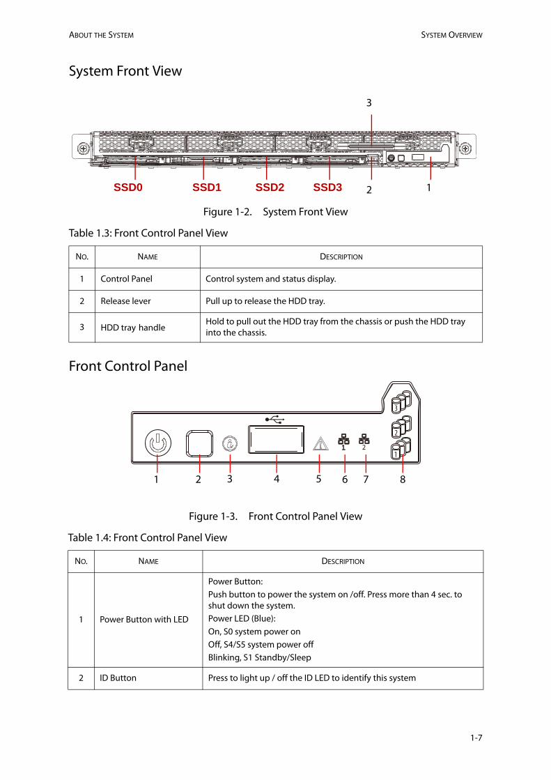
System Front View
Figure 1-2. System Front View
Front Control Panel
Figure 1-3. Front Control Panel View
Table 1.3: Front Control Panel View
NO. NAME DESCRIPTION
1 Control Panel Control system and status display.
2 Release lever Pull up to release the HDD tray.
3 HDD tray handleHold to pull out the HDD tray from the chassis or push the HDD tray into the chassis.
Table 1.4: Front Control Panel View
NO. NAME DESCRIPTION
1 Power Button with LED
Power Button:Push button to power the system on /off. Press more than 4 sec. to shut down the system.Power LED (Blue):On, S0 system power onOff, S4/S5 system power offBlinking, S1 Standby/Sleep
2 ID Button Press to light up / off the ID LED to identify this system
12
3
SSD0 SSD1 SSD2 SSD3
1
2
3
1 2 3 4 6 7 85
1-7

ABOUT THE SYSTEM SYSTEM OVERVIEW
3 ID LED (Blue)On, selected unit IDOff, no ID requested
4 USB 2.0 port Connects to USB device
5 Status LED (Amber)Off, NormalOn, DC off and critical errorBlinking, DC on and critical error.
6 LAN 1 LED (Blue)On, linkBlinking, LAN access
7 LAN 2 LED (Blue)On, linkBlinking, LAN access
8 HDD Array # LED (Amber)Off, HDD row # normalOn, HDD row # faultBlinking, Predictive Failure Analysis (PFA) error occurs on HDD row #
Table 1.4: Front Control Panel View (Continued)
1-8

ABOUT THE SYSTEM SYSTEM OVERVIEW
System Rear View
Figure 1-4. System Rear View
Rear I/O
Figure 1-5. Rea i/O View
Table 1.5: Rear Panel View
NO. NAME DESCRIPTION
1 PSU Redundant Power Supply Unit
2 Expansion slot Supports Quanta mezzanine (PCIe Gen3 x16)
3 System Rear I/O Mainboard (MB) I/O features
Table 1.6: Rear Panel View
NO. NAME DESCRIPTION
1 Management port Connects for remote management
2 VGA port Connects to a display device
3 COM port Connects to a serial device
4 USB ports Connects to USB device
5 LAN 1 port 1G Base-T RJ45 port
6 LAN 2 port 1G Base-T RJ45 port
1 2 3
1 2 3 4 65
1-9

ABOUT THE SYSTEM SYSTEM OVERVIEW
PSU View
Figure 1-6. PSU View
Table 1.7: PSU View
NO. NAME DESCRIPTION
1 Release latch Press and hold to unlock PSU from chassis bay.
2 AC input power connector Connect power plug.
3 Cable clip Secure the power cord.
4 Handle Hold to remove the PSU from the chassis bay.
5 PSU LED
Power LED (Green):
On: Output on and OK
Blinking: AC present
Status LED (Amber):
On: AC core unplugged or AC power lost; with a second power supply in parallel still with AC input power; Power supply criti-cal event causing shutdown
Blinking: Power supply warning events where the power sup-ply continues to operate; high temp, high power, high current, slow fan
1 2
3
4 5
1-10

ABOUT THE SYSTEM LED DEFINITIONS
LED Definitions
Front SAS/SATA HDD/SSD LED
The system features storage drive cage supporting up to 4x 2.5” SAS/SATA HDD/SSD (7mm) on front bottom chassis.
Each carrier has one HDD/SSD Present / Fault LED. See the following illustration and table for details.
Table 1.8: Front bottom 7mm 2.5” SAS/SATA HDD/SSD LED Description
LAN Port LED
The system mainboard has two i350 Ethernet controller.
Each RJ45 connector has two built-in LEDs. See the following illustration and table for details.
Figure 1-7. RJ45 LAN Connector
COLOR STATUS
Blue On Continuously Drive Access / Drive present
Amber On HDD Failed / Drive present
Off Slot Empty
Table 1.9: RJ45 LED Description
STATUS LINK / ACTIVITY LED SPEED LED
Unplug Off Off
1G Link with Active Green blinking Amber On
100M Link with Active Green blinking Green On
10M Link with Active Green blinking Off
SSD0 SSD1 SSD2 SSD3 7.5mm HDD/SSD Present / Fault LED
Link/Activity Speed
PIN 1Location
1-11

ABOUT THE SYSTEM LED DEFINITIONS
BMC Management Port LED
Figure 1-8. Management Port LED
Table 1.10: Management Port LED Behavior
STATUS SPEED LED LINK / ACTIVITY LED
Unplug Off Off
Plug in no access Off Green: on
1G Link +Active Amber: on Green: blinking
100M Link + Active Green: on Green: blinking
10M Link + Active Off Green: blinking
PSU1
Speed Link / Activity
1-12

Regulatory and Compliance InformationChapter 2
This section provides regulatory and compliance information applicable to this system.

Server Safety Information
To reduce the risk of bodily injury, electrical shock, fire, and equipment damage, read this
document and observe all warnings and precautions in this guide before installing or
maintaining your server product.
In the event of a conflict between the information in this document and information
provided with the product or on the website for a particular product, the product
documentation takes precedence.
Your server should be integrated and serviced only by technically qualified persons.
You must adhere to the guidelines in this guide and the assembly instructions in your server
manuals to ensure and maintain compliance with existing product certifications and
approvals. Use only the described, regulated components specified in this guide. Use of
other products / components will void the UL Listing and other regulatory approvals of the
product, and may result in noncompliance with product regulations in the region(s) in which
the product is sold.
Safety Warnings and Cautions
To avoid personal injury or property damage, before you begin installing the product, read,
observe, and adhere to all of the following safety instructions and information. The following
safety symbols may be used throughout the documentation and may be marked on the
product and / or the product packaging.
CAUTION Indicates the presence of a hazard that may cause minor
personal injury or property damage if the CAUTION is
ignored.
WARNING Indicates the presence of a hazard that may result in serious
personal injury if the WARNING is ignored.
Indicates potential hazard if indicated information is ignored.
Indicates shock hazards that result in serious injury or death
if safety instructions are not followed.
Indicates hot components or surfaces.
Indicates do not touch fan blades, may result in injury.
Indicates to unplug all AC power cord(s) to disconnect AC
power.
Please recycle battery.
The rail racks are designed to carry only the weight of the
server system. Do not use rail-mounted equipment as a
workspace. Do not place additional load onto any rail-
mounted equipment.
Indicates four or more people are required to safely handle
the system.

Intended Application Uses
This product was evaluated as Information Technology Equipment (ITE), which may be
installed in offices, schools, computer rooms, and similar commercial type locations. The
suitability of this product for other product categories and environments (such as medical,
industrial, residential, alarm systems, and test equipment), other than an ITE application, may
require further evaluation.
Site Selection
The system is designed to operate in a typical office environment. Choose a site that is:
Clean, dry, and free of airborne particles (other than normal room dust).
Well-ventilated and away from sources of heat including direct sunlight and radiators.
Away from sources of vibration or physical shock.
Isolated from strong electromagnetic fields produced by electrical devices.
In regions that are susceptible to electrical storms, we recommend you plug your system
into a surge suppressor and disconnect telecommunication lines to your modem during
an electrical storm.
Provided with a properly grounded wall outlet.
Provided with sufficient space to access the power supply cord(s), because they serve as
the product's main power disconnect.
Provided with either two independent AC power sources or two independent phases
from a s single source.
Equipment Handling Practices
Reduce the risk of personal injury or equipment damage:
Conform to local occupational health and safety requirements when moving and lifting
equipment.
Use mechanical assistance or other suitable assistance when moving and lifting
equipment.
To reduce the weight for easier handling, remove any easily detachable components.
Power and Electrical Warnings
Caution: The power button, indicated by the stand-by power marking, DOES NOT completely turn
off the system AC power, 5V standby power is active whenever the system is plugged in. To remove
power from system, you must unplug the AC power cord from the wall outlet. Your system may use
more than one AC power cord. Make sure all AC power cords are unplugged. Make sure the AC
power cord(s) is / are unplugged before you open the chassis, or add or remove any non hot-plug
components.
Do not attempt to modify or use an AC power cord if it is not the exact type required. A separate
AC cord is required for each system power supply.
Some power supplies in servers use Neutral Pole Fusing. To avoid risk of shock use caution when
working with power supplies that use Neutral Pole Fusing.
The power supply in this product contains no user-serviceable parts. Do not open the power
supply. Hazardous voltage, current and energy levels are present inside the power supply. Return
to manufacturer for servicing.

When replacing a hot-plug power supply, unplug the power cord to the power supply being
replaced before removing it from the server.
To avoid risk of electric shock, turn off the server and disconnect the power cord,
telecommunications systems, networks, and modems attached to the server before opening it.
Power Cord Warnings
If an AC power cord was not provided with your product, purchase one that is approved for
use in your country.
Caution: To avoid electrical shock or fire, check the power cord(s) that will be used with the product
as follows:
Do not attempt to modify or use the AC power cord(s) if they are not the exact type required to
fit into the grounded electrical outlets.
The power cord(s) must meet the following criteria:
The power cord must have an electrical rating that is greater than that of the electrical current
rating marked on the product.
The power cord must have safety ground pin or contact that is suitable for the electrical outlet.
The power supply cord(s) is / are the main disconnect device to AC power. The socket outlet(s) must
be near the equipment and readily accessible for disconnection.
The power supply cord(s) must be plugged into socket-outlet(s) that is /are provided with a suitable
earth ground.
System Access Warnings
Caution: To avoid personal injury or property damage, the following safety instructions apply
whenever accessing the inside of the product:
Turn off all peripheral devices connected to this product.
Turn off the system by pressing the power button to off.
Disconnect the AC power by unplugging all AC power cords from the system or wall outlet.
Disconnect all cables and telecommunication lines that are connected to the system.
Retain all screws or other fasteners when removing access cover(s). Upon completion of
accessing inside the product, refasten access cover with original screws or fasteners.
Do not access the inside of the power supply. There are no serviceable parts in the power
supply. Return to manufacturer for servicing.
Power down the server and disconnect all power cords before adding or replacing any non
hot-plug component.
When replacing a hot-plug power supply, unplug the power cord to the power supply being
replaced before removing the power supply from the server.
Caution: If the server has been running, any installed processor(s) and heat sink(s) may be hot.
Unless you are adding or removing a hot-plug component, allow the system to cool before
opening the covers. To avoid the possibility of coming into contact with hot component(s) during a
hot-plug installation, be careful when removing or installing the hot-plug component(s).
Caution: To avoid injury do not contact moving fan blades. If your system is supplied with a guard
over the fan, do not operate the system without the fan guard in place.

Rack Mount Warnings
Note: The following installation guidelines are required by UL for maintaining safety compliance
when installing your system into a rack.
The equipment rack must be anchored to an unmovable support to prevent it from tipping
when a server or piece of equipment is extended from it. The equipment rack must be
installed according to the rack manufacturer's instructions.
Install equipment in the rack from the bottom up, with the heaviest equipment at the
bottom of the rack.
Extend only one piece of equipment from the rack at a time.
You are responsible for installing a main power disconnect for the entire rack unit. This main
disconnect must be readily accessible, and it must be labeled as controlling power to the
entire unit, not just to the server(s).
To avoid risk of potential electric shock, a proper safety ground must be implemented for
the rack and each piece of equipment installed in it.
Elevated Operating Ambient - If installed in a closed or multi-unit rack assembly, the
operating ambient temperature of the rack environment may be greater than room ambient.
Therefore, consideration should be given to installing the equipment in an environment
compatible with the maximum ambient temperature (Tma) specified by the manufacturer.
Reduced Air Flow - Installation of the equipment in a rack should be such that the amount of
air flow required for safe operation of the equipment is not compromised.
Mechanical Loading - Mounting of the equipment in the rack should be such that a
hazardous condition is not achieved due to uneven mechanical loading.
Circuit Overloading - Consideration should be given to the connection of the equipment to
the supply circuit and the effect that overloading of the circuits might have on overcurrent
protection and supply wiring. Appropriate consideration of equipment nameplate ratings
should be used when addressing this concern.
Reliable Earthing - Reliable earthing of rack-mounted equipment should be maintained.
Particular attention should be given to supply connections other than direct connections to
the branch circuit (e.g. use of power strips).
Electrostatic Discharge (ESD)
Caution: ESD can damage drives, boards, and other parts. We recommend that you perform all
procedures at an ESD workstation. If one is not available, provide some ESD protection by wearing
an antistatic wrist strap attached to chassis ground -- any unpainted metal surface -- on your
server when handling parts.
Always handle boards carefully. They can be extremely sensitive to ESD. Hold boards only by their
edges. After removing a board from its protective wrapper or from the server, place the board
component side up on a grounded, static free surface. Use a conductive foam pad if available but
not the board wrapper. Do not slide board over any surface.
Other Hazards
Battery Replacement
Caution: There is the danger of explosion if the battery is incorrectly replaced. When replacing the
battery, use only the battery recommended by the equipment manufacturer.
Dispose of batteries according to local ordinances and regulations.

Do not attempt to recharge a battery.
Do not attempt to disassemble, puncture, or otherwise damage a battery.
Cooling and Airflow
Caution: Carefully route cables as directed to minimize airflow blockage and cooling problems. For
proper cooling and airflow, operate the system only with the chassis covers installed. Operating
the system without the covers in place can damage system parts. To install the covers:
Check first to make sure you have not left loose tools or parts inside the system.
Check that cables, add-in cards, and other components are properly installed.
Attach the covers to the chassis according to the product instructions.
Laser Peripherals or Devices
Caution: To avoid risk of radiation exposure and / or personal injury:
Do not open the enclosure of any laser peripheral or device
Laser peripherals or devices have are not serviceable
Return to manufacturer for servicing
Use certified Optical Fiber Transceiver Class I Laser Product
The power supply in this product contains no user-serviceable parts.
Refer servicing only to qualified personnel.
Do not attempt to modify or use the supplied AC power cord if it is not
the exact type required. A product with more than one power supply
will have a separate AC power cord for each supply.
The power button on the system does not turn off system AC power.
To remove AC power from the system, you must unplug each AC
power cord from the wall outlet or power supply.
The power cord(s) is considered the disconnect device to the main (AC)
power. The socket outlet that the system plugs into shall be installed
near the equipment and shall be easily accessible.
SAFETY STEPS: Whenever you remove the chassis covers to access the
inside of the system, follow these steps:
1. Turn off all peripheral devices connected to the system.
2. Turn off the system by pressing the power button.
3. Unplug all AC power cords from the system or from wall outlets.
4. Label and disconnect all cables connected to I/O connectors or
ports on the back of the system.
5. Provide some electrostatic discharge (ESD) protection by wearing an
antistatic wrist strap attached to chassis ground of the system-any
unpainted metal surface-when handling components.
6. Do not operate the system with the chassis covers removed.

After you have completed the six SAFETY steps above, you can remove
the system covers. To do this:
1. Unlock and remove the padlock from the back of the system if a
padlock has been installed.
2. Remove and save all screws from the covers.
3. Remove the cover(s).
For proper cooling and airflow, always reinstall the chassis covers
before turning on the system. Operating the system without the covers
in place can damage system parts. To install the covers:
1. Check first to make sure you have not left loose tools or parts inside
the system.
2. Check that cables, add-in cards, and other components are properly
installed.
3. Attach the covers to the chassis with the screws removed earlier,
and tighten them firmly.
4. Insert and lock the padlock to the system to prevent unauthorized
access inside the system.
5. Connect all external cables and the AC power cord(s) to the system.
A microprocessor and heat sink may be hot if the system has been
running. Also, there may be sharp pins and edges on some board and
chassis parts. Contact should be made with care. Consider wearing
protective gloves.
Danger of explosion if the battery is incorrectly replaced. Replace only
with the same or equivalent type recommended by the equipment
manufacturer. Dispose of used batteries according to manufacturer's
instructions.
The system is designed to operate in a typical office environment.
Choose a site that is:
Clean and free of airborne particles (other than normal room
dust).
Well ventilated and away from sources of heat including direct
sunlight.
Away from sources of vibration or physical shock.
Isolated from strong electromagnetic fields produced by electrical
devices.
In regions that are susceptible to electrical storms, we recommend
you plug your system into a surge suppressor and disconnect
telecommunication lines to your modem during an electrical
storm.
Provided with a properly grounded wall outlet.
Provided with sufficient space to access the power supply cord(s),
because they serve as the product's main power disconnect.

The rail racks are designed to carry only the weight of the server
system. Do not use rail-mounted equipment as a workspace. Do not
place additional load onto any rail-mounted equipment.
Heavy object. Indicates four or more people are required to safely
handle the system.
Product Regulatory Compliance Markings
This product is marked with the following Product Certification Markings:
Product Regulatory Compliance Markings
Regulatory
Compliance
Region Marking
cULus
Listing Mark USA /
Canada
CE Mark Europe
FCC Marking
(Class A) USA This device complies with Part 15 of the FCC Rules. Operation
of this device is subject to the following two conditions:
(1) This device may not cause harmful interference, and
(2) This device must accept any interference received, including
interference that may cause undesired operation.
ICES Canada CAN ICES-3 (A)/NMB-3(A)
VCCI Marking
(Class A) Japan
この裝置は、クラス A 情報技術裝置です。この裝置を家庭環境で使用すると電波妨害を
引き起こすことがあります。この場合には使用者が適切な対策を講ずるよう要求されることが
あります。 VCCI-A
BSMI Certification
Number & Class
A Warning
Taiwan
EAC Marking Russia
Recycling Package
Mark Other than
China
MSIP Korea
RCM Australia
警告使用者:
此為甲類資訊技術設備,於居住環境使用中時,可能會造成射頻擾
動,在此種情況下,使用者會被要求採取某些適當的對策。
Electromagnetic Compatibility Notices
FCC Verification Statement (USA)
This device complies with Part 15 of the FCC Rules. Operation is subject to the following two
conditions: (1) this device may not cause harmful interference, and (2) this device must
accept any interference received, including interference that may cause undesired operation.
This equipment has been tested and found to comply with the limits for a Class A digital
device, pursuant to part 15 of the FCC Rules. These limits are designed to provide
reasonable protection against harmful interference when the equipment is operated in a
commercial environment. This equipment generates, uses, and can radiate radio frequency
energy and, if not installed and used in accordance with the instruction manual, may cause
harmful interference to radio communications. Operation of this equipment in a residential
area is likely to cause harmful interference in which case the user will be required to correct
the interference at his own expense.
Europe (CE Declaration of Conformity)
This product has been tested in accordance too, and complies with the Low voltage Directive
(2006/95/EC) and EMC Directive (2004/108/EC). The product has been marked with the CE
Mark to illustrate its compliance.
VCCI (Japan)
English translation of the notice above:
This is a Class A product based on the standard of the Voluntary Control Council for
Interference (VCCI) from Information Technology Equipment. If this is used near a radio or
television receiver in a domestic environment, it may cause radio interference. Install and
use the equipment according to the instruction manual.
BSMI (Taiwan)
The BSMI Certification Marking and EMC warning is located on the outside rear area of the
product.
MSIP (Korea)
Ministry of Science, ICT & Future Planning (MSIP) Class A Statement:
English translation of the notice above:
“A” class equipment (info / technology equipment for business purpose)
警告使用者:
此為甲類資訊技術設備,於居住環境中使用時,可能會造成射頻擾動,在此種情況下,使用者會被要求採取某些適當
的對策。
この裝置は、クラス A情報技術裝置です。この裝置を家庭環境で使用すると電波妨害を引き起こすことがあります。この場合には使
用者が適切な対策を講ずるよう要求されることがあります。
VCCI-A
A 급 기기(업무용 정보통신기기)
이 기기는 업무용으로 전자파적합등록을 한 기기이오니 판매자 또는 사용자는 이 점을 주의하시기 바라며,
만약 잘못 판매 또는 구입하였을 때에는 가정용으로 교환하시기 바랍니다.

As this equipment has undergone EMC registration for business purpose, the seller and/or
the buyer is asked to beware of this point and in case a wrongful sale or purchase has been
made, it is asked that a change to household use be made.
Regulated Specified Components
To maintain the UL listing and compliance to other regulatory certifications and/or
declarations, the following regulated components must be used and conditions adhered to.
Interchanging or use of other component will void the UL listing and other product
certifications and approvals.
Updated product information for configurations can be found on the site at the following
URL:
www.QuantaQCT.com
If you do not have access to the Web address, please contact your local representative.
Add-in cards: must have a printed wiring board flammability rating of minimum UL94V-1.
Add-in cards containing external power connectors and/or lithium batteries must be UL
recognized or UL listed. Any add-in card containing modem telecommunication circuitry
must be UL listed. In addition, the modem must have the appropriate
telecommunications, safety, and EMC approvals for the region in which it is sold.
Peripheral Storage Devices: must be UL recognized or UL listed accessory and TUV or
VDE licensed. Maximum power rating of any one device is 19 watts. Total server
configuration is not to exceed the maximum loading conditions of the power supply.
Restriction of Hazardous Substances (RoHS) Compliance
Quanta® Computer Inc. has a system in place to restrict the use of banned substances in
accordance with the European Directive 2011/65/EU. Compliance is based on declaration
that materials banned in the RoHS Directive are either (1) below all applicable threshold
limits or (2) an approved / pending RoHS exemption applies.
RoHS implementation details are not fully defined and may change.
Threshold limits and banned substances are noted below:
Quantity limit of 0.1% by mass (1000 PPM) for:
— Lead
— Mercury
— Hexavalent Chromium
— Polybrominated Diphenyl Ethers (PBDE)
Quantity limit of 0.01% by mass (100 PPM) for:
— Cadmium
End of Life / Product Recycling
Product recycling and end-of-life take-back systems and requirements vary by country.
Contact the retailer or distributor of this product for information about product recycling
and / or take-back.