quantitative risk assessment for - welcome to...
TRANSCRIPT

Page 1 of 63
Quantitative Risk Assessment
For
Conducted by
Cholamandalam MS Risk Services Ltd. (An ISO 9001:2008 Certified Company)
Chennai, India www.cholarisk.com
December 2014
COROMANDEL INTERNATIONAL LIMITED
Fertilizers Plant, Kakinada
QRA Study Report for CIL Fertilizers, Kakinada
Document ID QRA/SR/CIL/14-15/01
Revision No. 00
Page 2 of 63
DOCUMENT HISTORY
S. No. Document Identification Revision Comment/Nature of changes No. Date
1 QRA/SR/CIL/14-15/01 00 24-12-2014 Preparation of original document
Prepared by
Reviewed by Approved by
Dhivya V Arul Arasu K
Cholamandalam MS Risk Services Ltd
Cholamandalam MS Risk Services Ltd
Coromandel International Limited, Kakinada
Disclaimer
This report is for the sole use by Coromandel for the purpose for which they have claimed it is required.
We are not responsible to any other person/party for any decision of such person/party based on this
report. It is hereby notified that reproduction, copying or otherwise quoting of our report or any part
thereof other than the aforementioned purpose, can be done only with our prior permission.
The report cannot be used or relied by Coromandel for any other purpose or any other third party for
any purpose whatsoever and we will not be liable which Coromandel may incur on this account
including in tort (including but not limited to negligence) arising out of or in connection with this Report.
This Report is not intended to identify all hazards which may exist nor is it intended to be an exhaustive
review of all possible eventualities. The recommendations for risk improvement contained in the report
are purely advisory and the decision and responsibility for implementation rests with Coromandel.

QRA Study Report for CIL Fertilizers, Kakinada
Document ID QRA/SR/CIL/14-15/01
Revision No. 00
Page 3 of 63
ACKNOWLEDGEMENT
Cholamandalam MS Risk Services gratefully acknowledges the co-operation received from the
management of Coromandel International Limited, Kakinada during the study. The CMSRSL team in
particular would like to thank the all the team members of Coromandel who had extended their
support and help throughout the study.

QRA Study Report for CIL Fertilizers, Kakinada
Document ID QRA/SR/CIL/14-15/01
Revision No. 00
Page 4 of 63
LIST OF ABBREVIATIONS
ALARP : As Low As Reasonably Practicable
ATM : Atmospheric
BLEVE : Boiling Liquid Expanding Vapor Explosion
CIL : Coromandel International Limited
CMSRSL : Cholamandalam MS Risk Services Ltd
CPR 18E : Commissie voor de Preventie van Rampem [Committee for Prevention of Disaster]
HAZOP : Hazard and Operability study
HSE UK : Health and Safety Executive, UK
IS : Indian Standard
IR : Individual Risk
LFL : Lower Flammability limit
LOC : Loss of Containment
OISD : Oil Industry Safety Directorate
QRA : Quantitative Risk Assessment
SR : Societal Risk
UEL : Upper Flammability Unit

QRA Study Report for CIL Fertilizers, Kakinada
Document ID QRA/SR/CIL/14-15/01
Revision No. 00
Page 5 of 63
TABLE OF CONTENTS ACKNOWLEDGEMENT ....................................................................................................................... 3
LIST OF ABBREVIATIONS ................................................................................................................... 4
CHAPTER 1 ...................................................................................................................................... 11
INTRODUCTION .............................................................................................................................. 11
1.1 INTRODUCTION ................................................................................................................... 12
1.2 SCOPE OF STUDY ................................................................................................................. 12
1.3 ABOUT THE CONSULTANTS ................................................................................................. 13
1.4 METHODOLOGY ADOPTED .................................................................................................. 13
CHAPTER 2 ...................................................................................................................................... 15
FACILITY DESCRIPTION .................................................................................................................... 15
2.1. FACILITY DESCRPTION .............................................................................................................. 16
CHAPTER 3 ...................................................................................................................................... 17
INTRODUCTION TO QUANTITATIVE RISK ASSESSMENT .................................................................. 17
3.1 OVERVIEW OF RISK ASSESSMENT ........................................................................................ 18
3.2 RISK CONCEPT ..................................................................................................................... 18
3.3 RISK ASSESSMENT PROCEDURE ........................................................................................... 19
3.3.1 SOFTWARE USED .......................................................................................................... 20
CHAPTER 4 ...................................................................................................................................... 22
RISK ASSESSMENT METHODOLOGY ................................................................................................ 22
4.1 QRA METHODOLGY ............................................................................................................. 23
4.2 IDENTIFICATION OF HAZARDS AND RELEASE SCENARIOS ................................................... 24
4.3 FACTORS FOR IDENTIFICATION OF HAZARDS ...................................................................... 24
4.4 TYPES OF OUTCOME EVENTS............................................................................................... 27
4.5 CONSEQUENCE CALCULATIONS ........................................................................................... 28
4.5.1 SOURCE STRENGTH PARAMETERS ............................................................................... 28
4.5.2 CONSEQUENTIAL EFFECTS............................................................................................ 28
4.6 SELECTION OF DAMAGE CRITERIA ....................................................................................... 29
4.7 PROBABILITIES .................................................................................................................... 31
4.7.1 POPULATION PROBABILITIES ....................................................................................... 31
QRA Study Report for CIL Fertilizers, Kakinada
Document ID QRA/SR/CIL/14-15/01
Revision No. 00
Page 6 of 63
4.7.2 FAILURE / ACCIDENT PROBABILITIES ........................................................................... 32
4.7.3 WEATHER PROBABILITIES ............................................................................................ 34
4.7.4 IGNITION PROBABILITIES ........................................................................................... 36
CHAPTER 5 ...................................................................................................................................... 38
CONSEQUENCE ANALYSIS ............................................................................................................... 38
5.1 SCENARIOS........................................................................................................................... 39
5.2 CONSEQUENCE ANALYSIS .................................................................................................... 40
5.2.1 SUMMARY OF JET FIRE ................................................................................................ 42
5.2.2 SUMMARY OF LATE POOL FIRE .................................................................................... 44
5.2.3 SUMMARY OF VAPOUR EXPLOSION ............................................................................ 44
5.2.4 SUMMARY OF BLEVE ................................................................................................... 46
5.2.5 SUMMARY OF FLAMMABLE GAS DISPERSION ............................................................. 46
CHAPTER 6 ...................................................................................................................................... 49
RISK ANALYSIS ................................................................................................................................ 49
CHAPTER 7 ...................................................................................................................................... 54
RISK CONTROL MEASURES .............................................................................................................. 54
7.1 PROPOSED RISK CONTROL MEASURES AS PER PRE-FEASIBILITY REPORT ............................. 55
7.2 RISK ACCEPTANCE ................................................................................................................ 56
7.3 RISK CONTROL MEASURES SUGGESTED ............................................................................... 57
REFERENCES .................................................................................................................................... 60
8.1 REFERENCES ......................................................................................................................... 61
CHAPTER 9 ...................................................................................................................................... 62
ANNEXURES .................................................................................................................................... 62
Annexure 1: Event tree analysis ...................................................................................................... 63
Annexure 2: Individual & Societal Risk contours ............................................................................. 63
Annexure 3: Google image of CIL plant, Kakinada .......................................................................... 63
QRA Study Report for CIL Fertilizers, Kakinada
Document ID QRA/SR/CIL/14-15/01
Revision No. 00
Page 7 of 63
LIST OF TABLES
Table 1: Details of LOC scenarios and their risk level ............................................................. 8
Table 2: Damages to human life due to heat radiation ........................................................ 30
Table 3: Effects due to incident radiation intensity .............................................................. 30
Table 4: Damage due to overpressures ............................................................................... 31
Table 6: Inputs to software and summary of outcomes ....................................................... 40
Table 7: Jet fire results ........................................................................................................ 42
Table 8: Vapour cloud explosion results .............................................................................. 44
Table 9: BLEVE results ......................................................................................................... 46
Table 10: Flammable gas dispersion results ......................................................................... 46
Table 11: Accident event frequency .................................................................................... 51

QRA Study Report for CIL Fertilizers, Kakinada
Document ID QRA/SR/CIL/14-15/01
Revision No. 00
Page 8 of 63
EXECUTIVE SUMMARY Coromandel International Ltd (CIL) intends to conduct the Quantitative Risk Assessment (QRA) study for the proposed installation of mounded LPG bullets for obtaining EC amendment in its Fertilizers plant located in Kakinada. Based on the data provided by the client for the study, potential scenarios, which can cause significant consequences like fire, explosion etc were identified, and the consequences of the scenarios were assessed using PHAST v6.7 software and the risk levels were evaluated using Phast Risk v6.7software, developed by DNV.
Table 1: Details of LOC scenarios and their risk level S.
No. Scenarios Individual Risk per avg. year
Societal Risk per avg. year
Storage Tanks &Tank Truck 1. Leak of LPG tank truck 5.29E-10 4.97E-10 2. Rupture of LPG tank truck 1.24E-07 1.24E-07 3. Leak of LPG mounded bullet 3.61E-09 3.11E-09 4. Rupture of LPG mounded bullet 7.41E-07 7.98E-07 5. Leak of LPG vaporizer 9.75E-09 9.19E-09 6. Rupture of LPG vaporizer 2.22E-08 2.24E-08
Pipelines & Unloading Arm 7. Leak of LPG unloading Hose / LPG Unloading Arm 5.50E-08 5.12E-08 8. Rupture of LPG unloading Hose / LPG Unloading Arm 5.83E-09 5.06E-09 9. Leak of LPG Compressor suction line 1.33E-09 1.21E-09 10. Rupture of LPG Compressor suction line 8.02E-09 7.89E-09 11. Leak of Compressor discharge line to tank truck 1.93E-09 1.78E-09 12. Rupture of Compressor discharge line to tank truck 1.35E-08 1.32E-08 13. Leak of LPG pipeline from tank truck to bullet 9.90E-09 9.22E-09 14. Rupture of LPG pipeline from tank truck to bullet 5.89E-08 5.86E-08 15. Leak of LPG pipeline from bullet to vaporizer 2.01E-08 1.89E-08 16. Rupture of LPG pipeline from bullet to vaporizer 2.66E-07 2.68E-07 17. Leak of LPG pipeline from vaporizer to boiler 5.70E-07 7.02E-07 18. Rupture of LPG pipeline from vaporizer to boiler 3.13E-07 3.56E-07 19. Leak of LPG pipeline from vaporizer to Dryer 6.90E-08 6.51E-08 20. Rupture of LPG pipeline from vaporizer to Dryer 1.95E-07 2.22E-07 21. Leak of LPG pipeline from vaporizer to flare 1.23E-07 1.17E-07 22. Rupture of LPG pipeline from vaporizer to flare 3.36E-07 4.06E-07 Legends:
With reference to the risk acceptance criteria specified by HSE, UK in IS 15656:2006 - Code of Practice on Hazard Identification and Risk Analysis it is observed that the risk levels of the proposed installation of
Unacceptable ALARP Acceptable

QRA Study Report for CIL Fertilizers, Kakinada
Document ID QRA/SR/CIL/14-15/01
Revision No. 00
Page 9 of 63
LPG mounded bullets in Coromandel Fertilizers plant are in acceptable region. The risk levels are expected to be remaining within these acceptable limits if all the control measures recommended in this report are implemented in addition to the existing risk control measures.
The following risk control measures are recommended in addition to the existing risk control
measures to maintain the risk levels within acceptable region:
SOP to address the operations pertaining to LPG receipt. Checklist to be prepared and records maintained for the same.
Fire water adequacy study to be carried out for the proposed LPG storage and handling facility
Integrity of the water sprinkler system pipeline to be ensured
Earthing /bonding of LPG handling pipelines to be periodically checked for integrity and continuity.
Onsite and offsite emergency response & disaster management plan should be developed for the proposed facility
MB Lal Committee Recommendations:
SIL (Safety Integrity Level) of the tank level control must be improved and independent overfill protection meeting the requirement of Part 1 of EN 61511 shall be provided. Ensure that all the instruments in the level control loop are SIL rated.
OISD recommendations:
OISD-Std-150: Design and safety requirements for LPG mounded storage facility
High level alarm should be set at not more than 85% level of the volumetric capacity of the vessel.
LPG bullet should have at least two Safety Relief Valves (SRV). The full flow capacity of each SRV on mounded vessel(s) should be minimum 30 % of the capacity required for an equivalent size of above ground vessel. Suitable gas detectors should be placed at critical locations in the LPG storage area such as near the ROVs, in inspection tunnel, inside the nozzle box enclosure (if provided) or dome connection, near water draining/ sampling points.
Audio-visual alarms showing the location of gas leakage should be provided on the control panel. First level alarm shall be set at 20% of Lower Explosive Limit (LEL) and second level alarm at 60 % of LEL.
Cathodic protection system should be provided maintained and tested as per Annexure 1 of OISD-Std-150.
Sub-soil water, rainwater or any other surface water should not be allowed to percolate in to the mound.
Provision should be made to monitor the settlement of the mound/ vessel by providing permanent reference points. A minimum of three reference points shall be provided to ascertain uniform/

QRA Study Report for CIL Fertilizers, Kakinada
Document ID QRA/SR/CIL/14-15/01
Revision No. 00
Page 10 of 63
differential settlement and also identify possible vessel bending (One each near the vessel ends and one in the middle.)
In case of non-availability of flare system, the discharge from safety valve shall be vented vertically upwards to atmosphere without any intermediate valve on downstream side at an elevation of 3-meter (minimum) from the top of the mound or exposed nozzle whichever is higher for effective dispersion of hydrocarbons.
Hydrant (s)/monitor(s) should be located at a safe place and shall not be installed within 15 meters from the exposed portion facilities/equipment to be protected. Adequate coverage to unprotected portions exposed to thermal radiation including the top of the mound and product pipelines to be ensured.
Safety Relief valves should be tested and calibrated every year by a competent person.
Other OISD standards:
Periodical Inspection and thickness measurement are to be carried out for the storage tanks
Ensure that the Gas Monitoring System is calibrated and tested as per OISD-Std-153
Ensure fixed fire protection systems for the truck unloading area conforming to OISD-Std-117.
Inspection and Maintenance of Pipelines to be carried as per OISD 130. Following need to be adhered in terms of inspection frequency:
Pressure Testing – Once every year
Painting – Once in 5 years
External Inspection – Yearly
MB Lal Committee Recommendations:
SIL (Safety Integrity Level) of the tank level control must be improved and independent overfill protection meeting the requirement of Part 1 of EN 61511 shall be provided. Ensure that all the instruments in the level control loop are SIL rated.
Conclusion
If all the existing risk control measures along with the additional risk control measures recommended in this report are implemented, the risks levels of the proposed installation of LPG mounded bullets/its associated pipelines in CIL Fertilizers plant are observed to remain within acceptable region.
QRA Study Report for CIL Fertilizers, Kakinada
Document ID QRA/SR/CIL/14-15/01
Revision No. 00
Page 11 of 63
CHAPTER 1 INTRODUCTION

QRA Study Report for CIL Fertilizers, Kakinada
Document ID QRA/SR/CIL/14-15/01
Revision No. 00
Page 12 of 63
1.1 INTRODUCTION Coromandel International Ltd (CIL) intends to conduct the Quantitative Risk Assessment (QRA) study for
the proposed installation of LPG mounded bullets for obtaining EC amendment in its Fertilizers plant
located in Kakinada.
The purpose of the study includes the following:
To identify and assess those hazards and risks arising from their activities connected to the LPG bullets and associated pipelines that require management to comply with regulatory requirements, company policy and business requirements
To eliminate or reduce to As Low As Reasonably Practical (ALARP) in terms of risk to human health, risk of injury, risk of damage to plant, equipment and environment, business interruption or loss etc.
1.2 SCOPE OF STUDY The main scope of the study is to carry out the QRA as per the Indian Standard (IS) 15656, Hazard
Identification and Risk Analysis - Code of Practice, including identification, screening and ranking of
various risk scenarios, consequence analysis of the various risk scenarios, and probabilistic assessment
of risks, recommendation and preparation of reports and relevant drawing showing damage and risk
contours.
The scope of the QRA is given below:
1. Study and identify the hazards and loss of containment events
2. Calculation of physical effects of accidental scenarios, which includes frequency analysis for
incident scenarios leading to hazards to people and facilities (flammable gas, fire & smoke,
explosion, overpressure and toxic gas hazards) and consequence analysis for the identified
hazards covering impact on people and potential escalation.
3. Individual risk quantification and contour mapping
4. Societal risk quantification and contour mapping
5. Hazard mitigation recommendations based on QRA
6. The Indian standard IS 15656: Code of practice – Hazard Identification and Risk analysis to be
adopted for this study.

QRA Study Report for CIL Fertilizers, Kakinada
Document ID QRA/SR/CIL/14-15/01
Revision No. 00
Page 13 of 63
1.3. ABOUT THE CONSULTANTS CMSRSL is a joint venture between the Murugappa Group and Mitsui Sumitomo Insurance Group of
Japan. CMSRSL is an approved HSE consultant of Kuwait Oil Company. CMSRSL offers specialized and
innovative risk management solutions to clients in India and rest of Asia. CMSRSL has carried out
consultancy and training services to over 2500 units/locations of various organizations belonging to 32
industrial sectors including refineries and petrochemical units. In addition to industrial sector and
service sector located in Kuwait, India, Hong Kong and Thailand, the Ministry of Environment and
Forests, Government of India and insurance companies located in India, Sri Lanka and Singapore have
been engaging the services of CMSRSL to carry out a number of risk Assessment and specialized safety
studies. CMSRSL also carries out similar studies for companies like Kuwait Oil Company, located outside
India. The team members have wide experience in risk management studies and have carried out
studies for a number of industrial sectors including refineries located in India and rest of Asia.
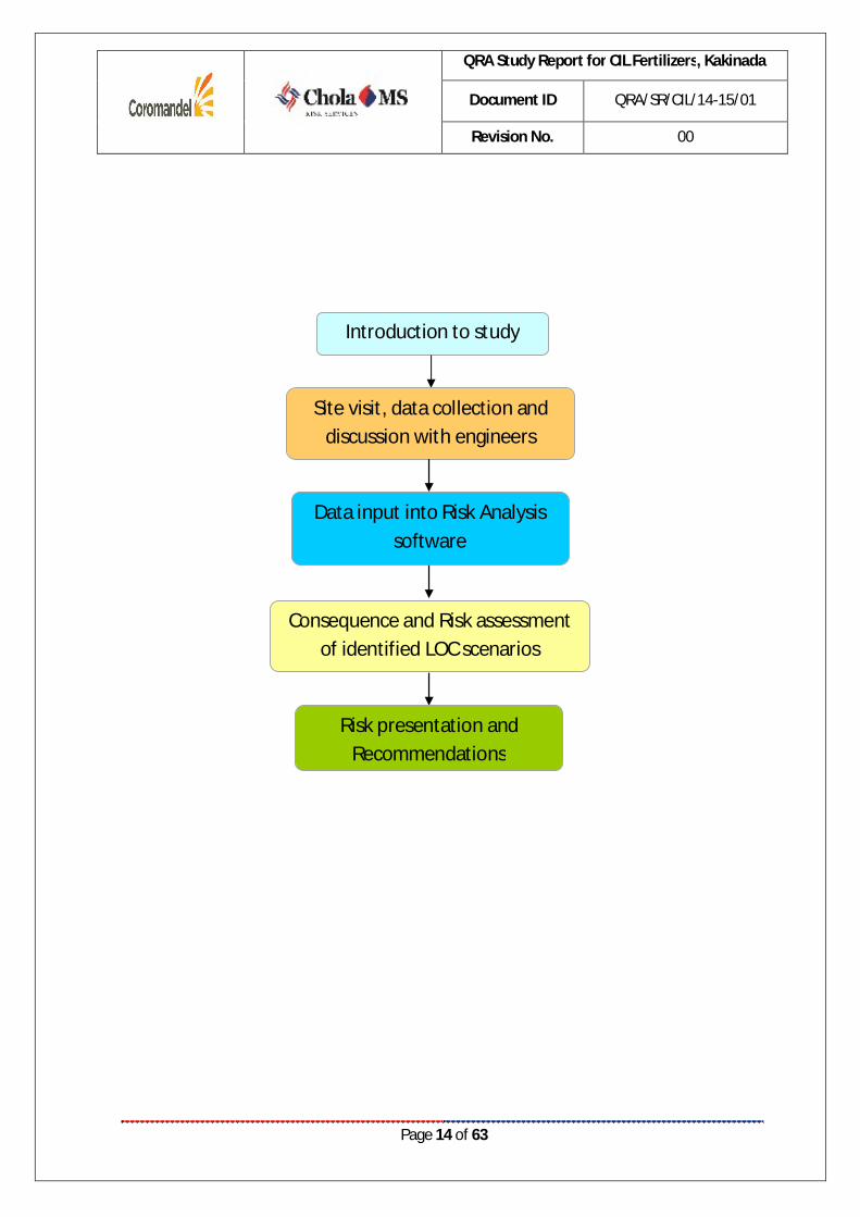
1.4. METHODOLOGY ADOPTED Detailed data request for risk Assessment study was submitted to the client before carrying out site visit
to familiarize the site officials on the nature of information that would be collected during site visit.
During site visit, CMSRS engineer had made a brief presentation to the site officials on the objective,
scope, methodology and deliverables of the risk Assessment study. Subsequently, site visit was carried
out for the entire facility to identify the potential hazard scenarios.
Then Risk Assessment calculations based on the collected data have been carried out at CMSRS office
using PHAST Risk Micro v6.7 software. Finally, risk reduction measures have been suggested based on
the risk levels.
The above adopted methodology has been depicted in the form of flow chart below:
QRA Study Report for CIL Fertilizers, Kakinada
Document ID QRA/SR/CIL/14-15/01
Revision No. 00
Page 14 of 63
Introduction to study
Site visit, data collection and discussion with engineers
Data input into Risk Analysis software
Consequence and Risk assessment of identified LOC scenarios
Risk presentation and Recommendations

QRA Study Report for CIL Fertilizers, Kakinada
Document ID QRA/SR/CIL/14-15/01
Revision No. 00
Page 15 of 63
CHAPTER 2 FACILITY DESCRIPTION
QRA Study Report for CIL Fertilizers, Kakinada
Document ID QRA/SR/CIL/14-15/01
Revision No. 00
Page 16 of 63
2.1. FACILITY DESCRPTION The existing facilities of CIL are located at Kakinada Rural Mandal, East Godavari District in Andhra
Pradesh. The existing plant is located at the intersection of latitude 16°59'19.18"N and
longitude 82°16'8.64"E. Samalkot-Kakinada Bypass is located at about 4.5 km.
CIL produces Di ammonium Phosphate, NPK, water soluble fertilizer and Sulphate of Potash
fertilizer with the production capacity of 19.25 MTPA.
CIL is proposed to install three number of 100 MT LPG mounded bullets in the existing facility. Currently
CIL is using Natural Gas (NG) as fuel in the existing facilities, which is being supplied by GAIL through a
100mm pipeline. NG is used in as fuel in the DAP Plant, Boiler House and Dryer. About 35000 Sm3/day
of NG is being consumed in the existing facility when the plant is operated at full capacity.
The following control measures are proposed to be installed at the LPG facility:
Installation of 3x100 MT LPG Mounded bullets with necessary passive and active safety systems as per OISD- 150 standard
LPG Truck Unloading Bay – vacuum type LPG unloading facility will be installed to avoid any spills and leakage of the LPG during the unloading operations.
Necessary excess flow check valves, Non-return valves and gas detectors will be installed on the LPG tanks to avoid any hazards during loading and transfer operations.
4 inch LPG supply line will be connected to the existing NG supply line with an isolation valve

QRA Study Report for CIL Fertilizers, Kakinada
Document ID QRA/SR/CIL/14-15/01
Revision No. 00
Page 17 of 63
CHAPTER 3
INTRODUCTION TO QUANTITATIVE RISK ASSESSMENT
QRA Study Report for CIL Fertilizers, Kakinada
Document ID QRA/SR/CIL/14-15/01
Revision No. 00
Page 18 of 63
3.1 OVERVIEW OF RISK ASSESSMENT Risk Assessment is proven valuable as a management tool in assessing the overall safety performance of
the chemical process Industry. Although management systems such as engineering codes, checklists,
and reviews by experienced engineers have provided substantial safety assurances, major incidents
involving numerous casualties, injuries and significant damage can occur – as illustrated by recent world-
scale catastrophes. Risk Assessment techniques provide advanced quantitative means to supplement
other hazard identification, analysis, assessment, and control and management methods to identify the
potential for such incidents and to evaluate control strategies.
The underlying basis of risk Assessment is simple in concept. It offers methods to answer the following
four questions:
1. What can go wrong?
2. What are the causes?
3. What are the consequences?
4. How likely is it?
This study tries to quantify the risks to rank them accordingly based on their severity and probability.
The report should be used to understand the significance of existing control measures and to follow the
measures continuously. Wherever possible the additional risk control measures should be adopted to
bring down the risk levels.
3.2 RISK CONCEPT
Risk in general is defined as a “measure of potential economic loss or human injury in terms of the
probability of the loss or injury occurring and magnitude of the loss or injury if it occurs”. Risk thus
comprises of two variables:
Magnitude of consequences and;
The probability of occurrence.
The results of risk Assessment are often reproduced as Individual and groups risks and are defined as
below.
Individual Risk is the “probability of death occurring as a result of accidents at a plant, installation or a
transport route expressed as a function of the distance from such an activity”. It is the frequency at
which an individual or an individual within a group may be expected to sustain a given level of harm
(typically death) from the realization of specific hazards. Such a risk actually exists only when a person is
permanently at that spot (out of doors).

QRA Study Report for CIL Fertilizers, Kakinada
Document ID QRA/SR/CIL/14-15/01
Revision No. 00
Page 19 of 63
The exposure of an individual is related to:
The likelihood of occurrence of an event involving a release;
Ignition of hydrocarbon;
The vulnerability of the person to the event;
The proportion of time the person will be exposed to the event (which is termed 'occupancy' in
the QRA terminology).
The second definition of risk involves the concept of the summation of risk from events involving many
fatalities within specific population groups. This definition is focused on the risk to society rather than to
a specific individual and is termed Societal Risk. In relation to the process operations we can identify
specific groups of people who work on or live close to the installation; for example communities living or
working close to the plant.
3.3 RISK ASSESSMENT PROCEDURE
Hazard identification and risk assessment involves a series of steps as follows:
Step 1: Identification of the Hazard
Hazard identification is a critical step in Risk Assessment. Many aids are available, including experience,
engineering codes, checklists, detailed process knowledge, equipment failure experience, hazard index
techniques, What-if Analysis, Hazard and Operability (HAZOP) Studies, Failure Mode and Effects Analysis
(FMEA), and Preliminary Hazard Analysis (PHA). In this phase all potential incidents are identified and
tabulated. Site visit and study of operations and documents like drawings, process write-up etc are used
for hazard identification.
Step 2: Assessment of the Risk
Consequence estimation is the methodology used to determine the potential for damage or injury from
specific incidents. A single incident (e.g. rupture of a pressurized flammable liquid tank) can have many
distinct incident outcomes (E.g. Unconfined Vapor Cloud Explosion (UVCE), Boiling Liquid Expanding
Vapor Explosion (BLEVE), flash fire, etc.)
Likelihood assessment is the methodology used to estimate the frequency or probability of occurrence
of an incident. Estimates may be obtained from historical incident data on failure frequencies, from
failure sequence models, such as fault trees and event trees or both. In this study the historical data
QRA Study Report for CIL Fertilizers, Kakinada
Document ID QRA/SR/CIL/14-15/01
Revision No. 00
Page 20 of 63
developed by software models and those collected by CPR18E – Committee for Prevention of Disasters,
Netherlands (Edition: PGS 3, 2005) are used.
Risks arising from the hazards are evaluated for its tolerability to personnel, the facility and the
environment. The acceptability of the estimated risk must then be judged based on IS-15656 criteria
appropriate to the particular situation.
Step 3: Elimination or Reduction of the Risk
This involves identifying opportunities to reduce the likelihood and/or consequence of an accident
Where deemed to be necessary.
Risk assessment combines the consequences and likelihood of all incident outcomes from all selected
incidents to provide a measure of risk. The risk of all selected incidents are individually estimated and
summed to give an overall measure of risk.
Risk-reduction measures include those to prevent incidents (i.e. reduce the likelihood of occurrence) to
control incidents (i.e. limit the extent and duration of a hazardous event) and to mitigate the effects (i.e.
reduce the consequences). Preventive measures, such as using inherently safer designs and ensuring
asset integrity, should be used wherever practicable.
In many cases, the measures to control and mitigate hazards and risks are simple and obvious and
involve modifications to conform to standard practice. The general hierarchy of risk reducing measures
is:
Prevention (by distance or design);
Detection (E.g. fire and gas, Leak detection);
Control (E.g. emergency shutdown and controlled depressurization);
Mitigation (E.g. fire fighting and passive fire protection);
Emergency response (In case safety barriers fail).
3.3.1 SOFTWARE USED:
PHAST v6.7 and PHAST Risk Micro v6.7
The software developed by DNV is used for risk assessment studies involving flammable and toxic
hazards where individual and societal risks are also to be identified. It enables the user to assess the
physical effects of accidental releases of toxic or flammable chemicals.
QRA Study Report for CIL Fertilizers, Kakinada
Document ID QRA/SR/CIL/14-15/01
Revision No. 00
Page 21 of 63
PHAST v6.7 is used for consequence calculations and PHAST Risk Micro v6.7 is used for risk calculations.
It contains a series of up to date models that allow detailed modeling and quantitative assessment of
release rate pool evaporation, atmospheric dispersion, vapor cloud explosion, combustion, heat
radiation effects from fires etc., The software is developed based on the hazard model given in TNO
Yellow Book as the basis.
The software is developed based on the various incidents that had occurred over past 25 years. CMSRS
has used the latest version of PHAST software for developing the consequences and risks for each
model.

QRA Study Report for CIL Fertilizers, Kakinada
Document ID QRA/SR/CIL/14-15/01
Revision No. 00
Page 22 of 63
CHAPTER 4 RISK ASSESSMENT METHODOLOGY

QRA Study Report for CIL Fertilizers, Kakinada
Document ID QRA/SR/CIL/14-15/01
Revision No. 00
Page 23 of 63
4.1 QRA METHODOLGY
Recommendation to reduce the consequence
Yes
No
Define the Goal (Statutory, Emergency Planning, Consequence, Etc.
Location, Layout, Process Parameters
Hazard Identification
Quantification of Hazard
Select most Credible Scenario Select Worst Case Scenario
Estimate Consequence Emergency Plan
Estimate Effect of Damage
Is Risk Acceptable?
End
Estimate Frequency of Occurrence
Estimate Risk
Prioritize and Reduce Risk
Frequency Estimation
QRA Study Report for CIL Fertilizers, Kakinada
Document ID QRA/SR/CIL/14-15/01
Revision No. 00
Page 24 of 63
4.2. IDENTIFICATION OF HAZARDS AND RELEASE SCENARIOS A technique commonly used to generate an incident list is to consider potential leaks and major releases
from fractures of all process pipelines and associated facilities. The containment is defined as one or
several devices, any parts which are permanently in open contact with one another, and which are
intended to contain one or multiple substances. A Loss of Containment is one containment system that
will not lead to the release of significant quantities of hazardous substance from other
containment systems.
The following data were collected to envisage scenarios:
Composition of materials stored in storage tanks/flowing through pipeline;
Inventory of materials stored in storage tanks/tank trucks;
Flow rate of materials passing through pipelines;
Storage tanks/pipeline conditions (phase, temperature, pressure);
Connecting piping and piping dimensions.
Accidental release of flammable liquids/gases can result in severe consequences. Delayed ignition of
flammable gases can result in blast overpressures covering large areas. This may lead to extensive loss of
life and property. In contrast, fires have localized consequences. Fires can be put out or contained in
most cases; there are few mitigating actions one can take once a flammable gas or a vapor cloud gets
released. Major accident hazards arise, therefore, consequent upon the release of flammable gases.
4.3 FACTORS FOR IDENTIFICATION OF HAZARDS In any installation, main hazard arises due to loss of containment during handling of flammable
chemicals. To formulate a structured approach to identification of hazards, an understanding of
contributory factors is essential.
Inventory
Inventory analysis is commonly used in understanding the relative hazards and short listing of release
scenarios. Inventory plays an important role in regard to the potential hazard. Larger the inventory of a
vessel or a system, larger is the quantity of potential release. A practice commonly used to generate an
incident list is to consider potential leaks and major releases from fractures of pipelines and
vessels/tanks containing sizable inventories.

QRA Study Report for CIL Fertilizers, Kakinada
Document ID QRA/SR/CIL/14-15/01
Revision No. 00
Page 25 of 63
Parameters Potential vapor release for the same material depends significantly on the operating conditions. This
operating range is enough to release a large amount of vapor in case of a leak/rupture, therefore the
storage tank/pipeline leaks and ruptures need to be considered in the risk Assessment calculations.
Blast overpressures depend upon the reactivity class of material and the amount of gas between two
explosive limits. For example, LPG once released and not ignited immediately is expected to give rise to
a vapor cloud. These vapors in general have medium reactivity and in case of confinement of the gas
cloud, on delayed ignition may result in an explosion and overpressures.
Initiating Events
Both the complexity of study and the number of incident outcome cases are affected by the range of
initiating events and incidents covered. This not only reflects the inclusion of accidents and/or non-
accident-initiated events, but also the size of those events. For instance studies may evaluate one or
more of the following:
Catastrophic failure of storage tanks, tank trucks
Large hole (large continuous release)
Small hole (continuous release)
Leaks at fittings or valves (small continuous release)
In general, quantitative studies do not include very small continuous releases or short duration small
releases if past experience or preliminary consequence modeling shows that such releases do not
contribute to the overall risk levels.
Selection of initiating events and incidents
The selection of initiating events and incidents should take into account the goals or objectives of the
study and the data requirements. The data requirements increase significantly when non-accident –
initiated events are included and when the number of release size increase. While the potential range of
release sizes is tremendous, groupings are both appropriate and necessitated by data restrictions. The
main reasons for including release sizes other than the catastrophic rupture are to reduce the
conservatism in an analysis and to better understand the relative contributions to risk of small versus large
releases.
As per Reference Manual Bevi Risk assessment version 3.2, only the Loss of Containment (LOC) which is basically the release scenarios contributing to the individual and/or societal risk are included in the QRA. LOC scenarios for the installation are included only if the following conditions are fulfilled:

QRA Study Report for CIL Fertilizers, Kakinada
Document ID QRA/SR/CIL/14-15/01
Revision No. 00
Page 26 of 63
Frequency of occurrence is equal to or greater than 10-9; and
Lethal damage (1% probability) occurs outside the establishment’s boundary or the transport
route.
There may be number of accidents that may occur quite frequently, but due to proper control measures or fewer quantities of chemicals released, they are controlled effectively. A few examples are a leak from a gasket, pump or valve, release of a chemical from a vent or relief valve, and fire in a pump due to overheating. These accidents generally are controlled before they escalate by using control systems and monitoring devices.
Below LOC scenarios are identified for the CIL, Kakinada.
S. No. Scenarios Storage Tanks, Tank Truck
1. Leak of LPG tank truck 2. Rupture of LPG tank truck 3. Leak of LPG mounded bullet 4. Rupture of LPG mounded bullet 5. Leak of LPG vaporizer 6. Rupture of LPG vaporizer
Pipelines & Unloading Arm 7. Leak of LPG unloading Hose / LPG Unloading Arm 8. Rupture of LPG unloading Hose / LPG Unloading Arm 9. Leak of LPG Compressor suction line 10. Rupture of LPG Compressor suction line 11. Leak of Compressor discharge line to tank truck 12. Rupture of Compressor discharge line to tank truck 13. Leak of LPG pipeline from tank truck to bullet 14. Rupture of LPG pipeline from tank truck to bullet 15. Leak of LPG pipeline from bullet to vaporizer 16. Rupture of LPG pipeline from bullet to vaporizer 17. Leak of LPG pipeline from vaporizer to boiler 18. Rupture of LPG pipeline from vaporizer to boiler 19. Leak of LPG pipeline from vaporizer to Dryer 20. Rupture of LPG pipeline from vaporizer to Dryer 21. Leak of LPG pipeline from vaporizer to flare 22. Rupture of LPG pipeline from vaporizer to flare

QRA Study Report for CIL Fertilizers, Kakinada
Document ID QRA/SR/CIL/14-15/01
Revision No. 00
Page 27 of 63
4.4 TYPES OF OUTCOME EVENTS Depending on the considered LPG LOC scenarios the following outcomes are expected:
Jet fires
Flammable gas dispersion (Flash Fire)
Vapor Cloud Explosion (VCE)
BLEVE
Jet fires
Jet fire occurs when a pressurized release (of a flammable gas or vapor) is ignited by any source. They tend to be localized in effect and are mainly of concern in establishing the potential for domino effects and employee safety zones rather than for community risks.
The jet fire model is based on the radiant fraction of total combustion energy, which is assumed to arise from a point slowly along the jet flame path. The jet dispersion model gives the jet flame length.
Flammable gas dispersion (Flash fire)
A flash fire is a sudden, intense fire caused by ignition of a mixture of air and a dispersed flammable gas. It is characterized by high temperature, short duration, and a rapidly moving flame front.
Vapor Cloud Explosion (VCE)
Vapor cloud explosion is the result of flammable materials in the atmosphere, a subsequent dispersion phase, and after some delay an ignition of the vapor cloud. Turbulence is the governing factor in blast generation, which could intensify combustion to the level that will result in an explosion. Obstacles in the path of vapor cloud or when the cloud finds a confined area, e.g. as under the bullets, often create turbulence. The VCE will result in overpressures.
Boiling Liquid Expanding Vapour Explosion (BLEVE)
A boiling liquid expanding vapor explosion (BLEVE) is an explosion caused by the rupture of a vessel containing a pressurized liquid above its boiling point.

QRA Study Report for CIL Fertilizers, Kakinada
Document ID QRA/SR/CIL/14-15/01
Revision No. 00
Page 28 of 63
4.5 CONSEQUENCE CALCULATIONS
In consequence analysis, use is made of a number of calculation models to estimate the physical effects of an accident (spill of hazardous material) and to predict the damage (lethality, injury, material destruction) of the effects.
Accidental release of flammable liquids can result in severe consequences. Immediate ignition of the pressurized chemical will result in a jet flame. Delayed ignition of flammable vapors can result in blast overpressures covering large areas.
The calculations can roughly be divided in three major groups:
a. Determination of the source strength parameters;
b. Determination of the consequential effects;
c. Determination of the damage or damage distances.
The basic physical effect models consist of the following.
4.5.1 SOURCE STRENGTH PARAMETERS
Calculation of the outflow of liquid vapors out of a vessel/tank or a pipe, in case of rupture. Also two-phase outflow can be calculated.
Calculation, in case of liquid outflow, of the instantaneous flash evaporation and of the dimensions of the remaining liquid pool.
Calculation of the evaporation rate, as a function of volatility of the material, pool dimensions and wind velocity.
Source strength equals pump capacities, etc. in some cases.
4.5.2 CONSEQUENTIAL EFFECTS
Dispersion of gaseous material in the atmosphere as a function of source strength, relative density of the gas, weather conditions and topographical situation of the surrounding area.
Intensity of heat radiation [in kW/ m2] due to a fire or a BLEVE, as a function of the distance to the source.
Energy of vapor cloud explosions [in N/m2], as a function of the distance to the distance of the exploding cloud.
Concentration of gaseous material in the atmosphere, due to the dispersion of evaporated chemical. The latter can be either explosive or toxic.

QRA Study Report for CIL Fertilizers, Kakinada
Document ID QRA/SR/CIL/14-15/01
Revision No. 00
Page 29 of 63
It may be obvious, that the types of models that must be used in a specific risk study strongly depend upon the type of material involved:
Gas, vapor, liquid, solid?
Inflammable, explosive, toxic, toxic combustion products?
Stored at high/low temperatures or pressure?
Controlled outflow (pump capacity) or catastrophic failure?
4.6 SELECTION OF DAMAGE CRITERIA
The damage criteria give the relation between the extents of the physical effects (exposure) and the effect of consequences. For assessing the effects on human beings consequences are expressed in terms of injuries and the effects on equipment / property in terms of monetary loss.
The effect of consequences for explosion or fire can be categorized as:
Damage caused by heat radiation on material and people
Damage caused by explosion on structure and people
In consequence analysis studies, in principle three types of exposure to hazardous effects are distinguished:
1. Heat radiation due to fires - in this study, the concern is that of Jet fires and pool fires
2. Explosions
3. Toxic effects, from toxic materials or toxic combustion products.
In this study, “toxic effects are not applicable”.
The knowledge about these relations depends strongly on the nature of the exposure. Following are the criteria selected for damage estimation:

QRA Study Report for CIL Fertilizers, Kakinada
Document ID QRA/SR/CIL/14-15/01
Revision No. 00
Page 30 of 63
Heat Radiation The effect of fire on a human being is in the form of burns. There are three categories of burn such
as first degree, second degree and third degree burns. The consequences caused by exposure to
heat radiation are a function of:
The radiation energy onto the human body [kW/m2];
The exposure duration [sec];
The protection of the skin tissue (clothed or naked body).
The limits for 1% of the exposed people to be killed due to heat radiation, and for second-degree burns
are given in the table below:
Table 2: Damages to human life due to heat radiation
Exposure Duration
Radiation energy (1% lethality), kW/m2
Radiation energy (2nd degree burns), kW/m2
Radiation energy (1st degree burns), kW/m2
10 sec 21.2 16 12.5 30 sec 9.3 7.0 4.0
Table 3: Effects due to incident radiation intensity
Incident Radiation (Kw/m2)
Type of Damage
0.7 Equivalent to Solar Radiation 1.6 No discomfort for long exposure
4.0 Sufficient to cause pain within 20 sec. Blistering of skin (first degree burns are likely)
9.5 Pain threshold reached after 8 sec. second degree burns after 20 sec.
12.5 Minimum energy required for piloted ignition of wood, melting plastic tubing etc.
37.5 Heavy Damage to process equipments
Reference: CCPS, Guidelines for Chemical Process Quantitative Risk Analysis The actual results would be less severe due to the various assumptions made in the models arising out
of the flame geometry, emissivity, angle of incidence, view factor and others. The radiation output of
the flame would be dependent upon the fire size, extent of mixing with air and the flame temperature.
Some fraction of the radiation is absorbed by carbon dioxide and water vapor in the intervening
atmosphere. Finally the incident flux at an observer location would depend upon the radiation view

QRA Study Report for CIL Fertilizers, Kakinada
Document ID QRA/SR/CIL/14-15/01
Revision No. 00
Page 31 of 63
factor, which is a function of the distance from the flame surface, the observer’s orientation and the
flame geometry.
As per the guidelines of CPR 18 E Purple Book:
« The lethality of a jet fire and pool fire is assumed to be 100% for the people who are caught in
the flame. Outside the flame area, the lethality depends on the heat radiation distances.
« For the flash fires lethality is taken as 100% for all the people caught outdoors and for 10% who
are indoors within the flammable cloud. No fatality has been assumed outside the flash fire
area.
« Overpressure more than 0.3 bar corresponds approximately with 50% lethality.
« An overpressure above 0.2 bar would result in 10% fatalities.
« An overpressure less than 0.1 bar would not cause any fatalities to the public.
« 100% lethality is assumed for all people who are present within the cloud proper.
Table 4: Damage due to overpressures
Peak Overpressure
Damage Type Description
0.30 bar Heavy Damage Major damage to plant equipment structure 0.10 bar Moderate Damage Repairable damage to plant equipment and structure 0.03 bar Significant Damage Shattering of glass 0.01 bar Minor Damage Crack in glass
4.7 PROBABILITIES 4.7.1 POPULATION PROBABILITIES It is necessary to know the population exposure in order to estimate the consequences and the risk
resulting from an incident. The exposed population is often defined using a population density.
Population densities are an important part of a QRA for several reasons. The most notable is that the
density is typically used to determine the number of people affected by a given incident with a specific
hazard area. Sometimes, population data are available in sketchy forms. In the absence of specific
population data default categories can be used.
The population density can be averaged over the whole area that may be affected or the area can be
subdivided into any number of segments with a separate population density for each individual
segment.
In this study, based on the discussions with CIL officials, the following population data were considered
for the study for the habitations located in the vicinity of the facility.
QRA Study Report for CIL Fertilizers, Kakinada
Document ID QRA/SR/CIL/14-15/01
Revision No. 00
Page 32 of 63
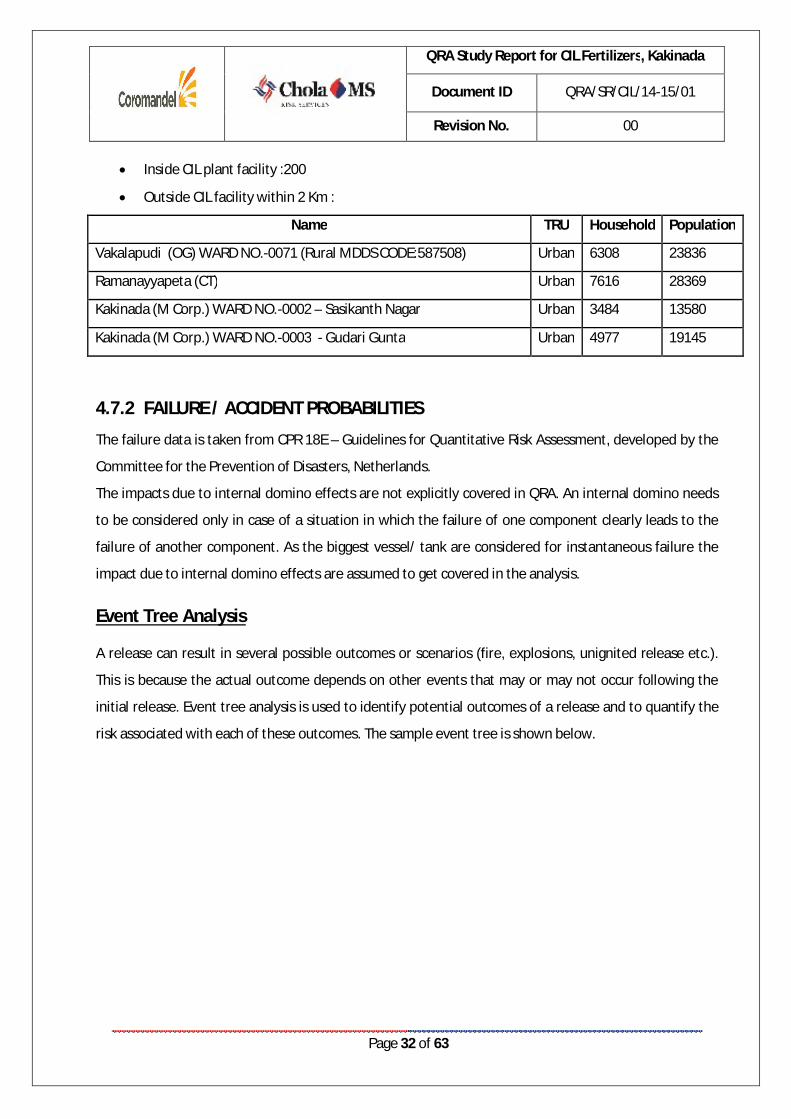
Inside CIL plant facility :200
Outside CIL facility within 2 Km :
Name TRU Household Population
Vakalapudi (OG) WARD NO.-0071 (Rural MDDS CODE:587508) Urban 6308 23836
Ramanayyapeta (CT) Urban 7616 28369
Kakinada (M Corp.) WARD NO.-0002 – Sasikanth Nagar Urban 3484 13580
Kakinada (M Corp.) WARD NO.-0003 - Gudari Gunta Urban 4977 19145
4.7.2 FAILURE / ACCIDENT PROBABILITIES
The failure data is taken from CPR 18E – Guidelines for Quantitative Risk Assessment, developed by the
Committee for the Prevention of Disasters, Netherlands.
The impacts due to internal domino effects are not explicitly covered in QRA. An internal domino needs
to be considered only in case of a situation in which the failure of one component clearly leads to the
failure of another component. As the biggest vessel/ tank are considered for instantaneous failure the
impact due to internal domino effects are assumed to get covered in the analysis.
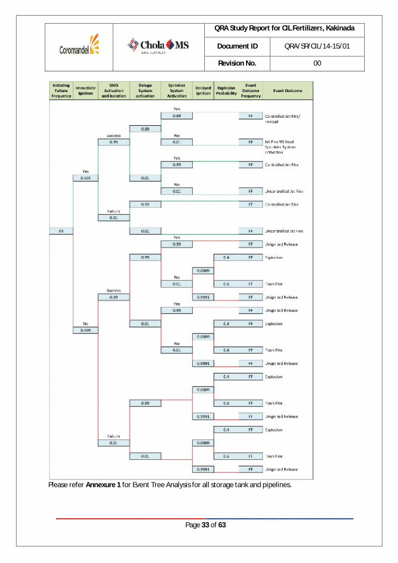
Event Tree Analysis
A release can result in several possible outcomes or scenarios (fire, explosions, unignited release etc.).
This is because the actual outcome depends on other events that may or may not occur following the
initial release. Event tree analysis is used to identify potential outcomes of a release and to quantify the
risk associated with each of these outcomes. The sample event tree is shown below.
QRA Study Report for CIL Fertilizers, Kakinada
Document ID QRA/SR/CIL/14-15/01
Revision No. 00
Page 33 of 63
Please refer Annexure 1 for Event Tree Analysis for all storage tank and pipelines.
QRA Study Report for CIL Fertilizers, Kakinada
Document ID QRA/SR/CIL/14-15/01
Revision No. 00
Page 34 of 63
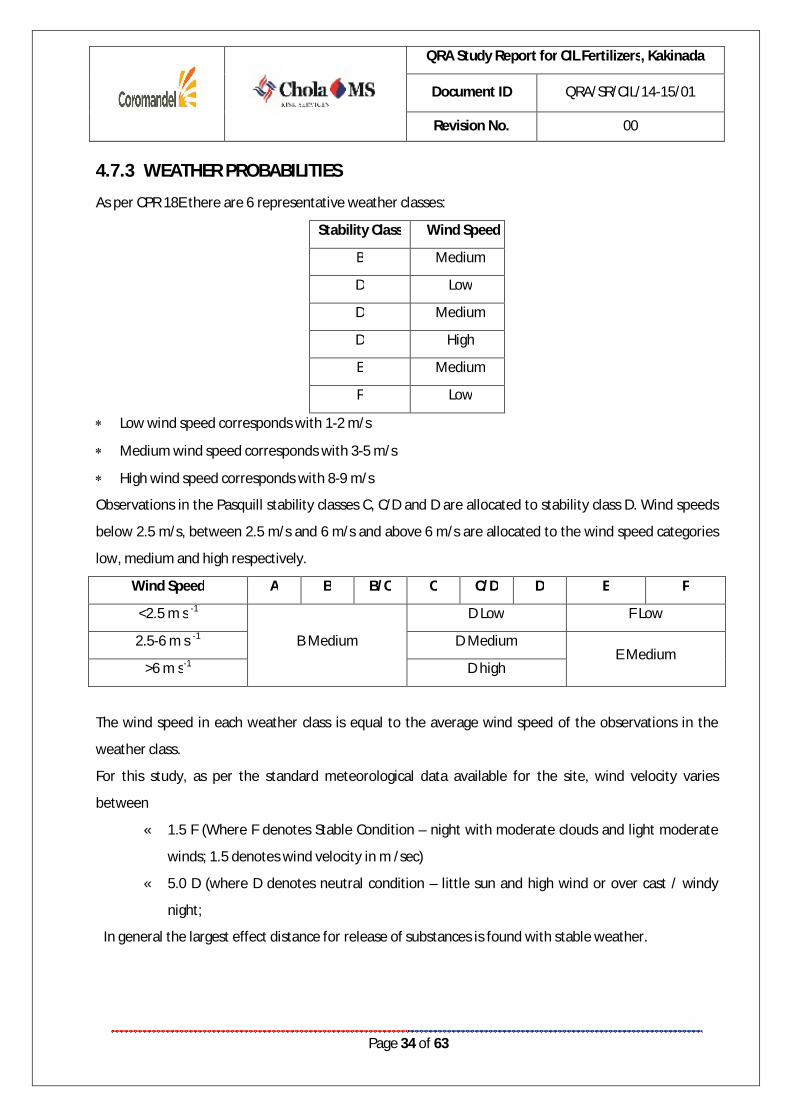
4.7.3 WEATHER PROBABILITIES
As per CPR 18E there are 6 representative weather classes:
Stability Class Wind Speed
B Medium
D Low
D Medium
D High
E Medium
F Low
Low wind speed corresponds with 1-2 m/s
Medium wind speed corresponds with 3-5 m/s
High wind speed corresponds with 8-9 m/s
Observations in the Pasquill stability classes C, C/D and D are allocated to stability class D. Wind speeds
below 2.5 m/s, between 2.5 m/s and 6 m/s and above 6 m/s are allocated to the wind speed categories
low, medium and high respectively.
Wind Speed A B B/C C C/D D E F
<2.5 m s -1
B Medium
D Low F Low
2.5-6 m s -1 D Medium E Medium
>6 m s-1 D high
The wind speed in each weather class is equal to the average wind speed of the observations in the
weather class.
For this study, as per the standard meteorological data available for the site, wind velocity varies
between
« 1.5 F (Where F denotes Stable Condition – night with moderate clouds and light moderate
winds; 1.5 denotes wind velocity in m /sec)
« 5.0 D (where D denotes neutral condition – little sun and high wind or over cast / windy
night;
In general the largest effect distance for release of substances is found with stable weather.
QRA Study Report for CIL Fertilizers, Kakinada
Document ID QRA/SR/CIL/14-15/01
Revision No. 00
Page 35 of 63
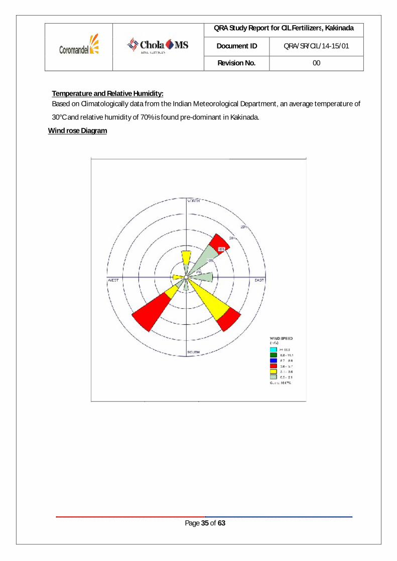
Temperature and Relative Humidity: Based on Climatologically data from the Indian Meteorological Department, an average temperature of
30°C and relative humidity of 70% is found pre-dominant in Kakinada.
Wind rose Diagram

QRA Study Report for CIL Fertilizers, Kakinada
Document ID QRA/SR/CIL/14-15/01
Revision No. 00
Page 36 of 63
4.7.4 IGNITION PROBABILITIES
Immediate Ignition Probability:
Immediate ignition can be considered as the situation where the fluid ignites immediately on release through auto-ignition or because the accident which causes the release also provided an ignition source. Immediate ignition probability is assumed based on the CPR 18E - Guidelines for Quantitative Risk Assessment, developed by the Committee for the Prevention of Disasters, Netherlands.
Probability of Immediate Ignition
Substance category Source term Continuous
Source term Instantaneous
Probability of direct ignition
Category 0 average/ high reactivity
< 10 kg/s < 1,000 kg 0.2 10 – 100 kg/s > 100 kg/s
1000 – 10,000 kg > 10,000 kg
0.5 0.7
Category 0 low reactivity
< 10 kg/s 10 – 100 kg/s > 100 kg/s
< 1,000 kg 1000 – 10,000 kg > 10,000 kg
0.02 0.04 0.09
Category 1 All flow rates All quantities 0.065 Category 2 All flow rates All quantities 0.01 Category 3, 4 All flow rates All quantities 0
Category 0(extremely flammable):
Liquid substances and preparations with a flash point lower than 0 °C and a boiling point (or the start of a boiling range) less than or equal to 35 °C.
Gaseous substances and preparations that may ignite at normal temperature and pressure when exposed to air.
For this study LPG is considered under Category 0.
Delayed Ignition Probability:
Delayed ignition is the result of the build-up of a flammable vapour cloud which is ignited by a source remote from the release point. It is assumed to result in flash fires or explosions, and also to burn back to the source of the leak resulting in a jet fire and/or a pool fire. Delayed ignition probability is assumed based on the CPR 18E - Guidelines for Quantitative Risk Assessment, developed by the Committee for the Prevention of Disasters, Netherlands.

QRA Study Report for CIL Fertilizers, Kakinada
Document ID QRA/SR/CIL/14-15/01
Revision No. 00
Page 37 of 63
Probability of Delayed Ignition
Source type Ignition source Probability of ignition
Point source Adjacent process installation Flare Oven (outside) Oven (inside) Boiler (outside) Boiler (inside)
0.5 1.0 0.9 0.45 0.45 0.23
Line source high-voltage cable (per 100 m) Ship
0.2 0.5
Population source Households (per person) Offices (per person)
0.01 0.01

QRA Study Report for CIL Fertilizers, Kakinada
Document ID QRA/SR/CIL/14-15/01
Revision No. 00
Page 38 of 63
CHAPTER 5 CONSEQUENCE ANALYSIS

QRA Study Report for CIL Fertilizers, Kakinada
Document ID QRA/SR/CIL/14-15/01
Revision No. 00
Page 39 of 63
5.1 SCENARIOS
This section documents the consequence-distance calculations, which have been computed for the
accident release scenarios considered.
In risk Assessment studies contributions from low frequency - high severity effect as well as high
frequency - low severity events are distinguished. Following are the potential Loss of Containment
scenarios envisaged for CIL, Kakinada.
Below LOC Scenarios are identified for the CIL,Kakinada.
S. No. Scenarios Storage Tanks, Tank Truck
1. Leak of LPG tank truck 2. Rupture of LPG tank truck 3. Leak of LPG mounded bullet 4. Rupture of LPG mounded bullet 5. Leak of LPG vaporizer 6. Rupture of LPG vaporizer
Pipelines & Unloading Arm 7. Leak of LPG unloading Hose / LPG Unloading Arm 8. Rupture of LPG unloading Hose / LPG Unloading Arm 9. Leak of LPG Compressor suction line 10. Rupture of LPG Compressor suction line 11. Leak of Compressor discharge line to tank truck 12. Rupture of Compressor discharge line to tank truck 13. Leak of LPG pipeline from tank truck to bullet 14. Rupture of LPG pipeline from tank truck to bullet 15. Leak of LPG pipeline from bullet to vaporizer 16. Rupture of LPG pipeline from bullet to vaporizer 17. Leak of LPG pipeline from vaporizer to boiler 18. Rupture of LPG pipeline from vaporizer to boiler 19. Leak of LPG pipeline from vaporizer to Dryer 20. Rupture of LPG pipeline from vaporizer to Dryer 21. Leak of LPG pipeline from vaporizer to flare 22. Rupture of LPG pipeline from vaporizer to flare

QRA Study Report for CIL Fertilizers Plant,
Kakinada
Document ID QRA/SR/CIL/14-15/01
Revision No. 00
Page 40 of 63
5.2. CONSEQUENCE ANALYSIS
Sudden release of hydrocarbon can result in a number of accident situations. As large number of failure cases can lead to the same type of consequences,
representative failure cases are selected for this analysis. The failure cases are based on conservative assumptions and engineering judgment. Typically,
failure models are considered for 100% pipe diameter/catastrophic rupture of vessels for rupture and 10% leak (hole size max 50 mm) based on the
guidelines of CPR 18 E.
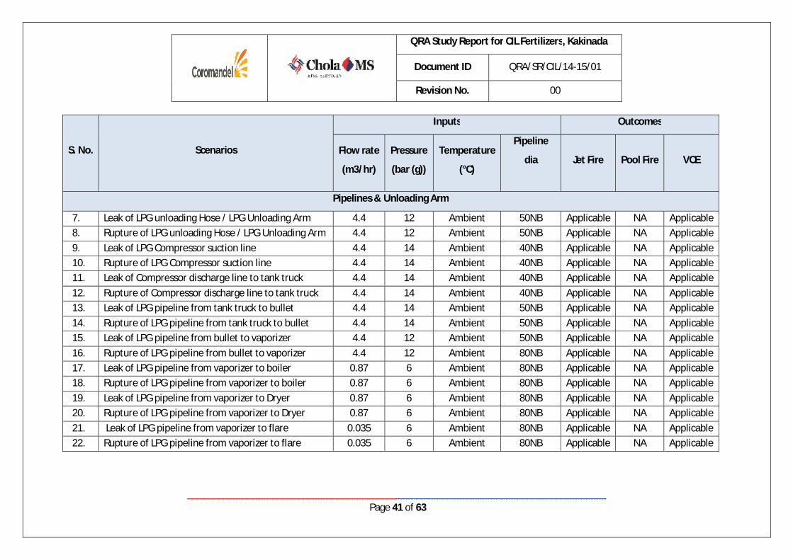
Table 6: Inputs to software and summary of outcomes
S. No. Scenarios
Inputs Outcomes
Quantity
(MT)
Pressure
(bar (g))
Temperature
(°C)
Tank
Height
(m)
Jet Fire Pool Fire VCE
Storage Tanks, Tank Truck
1. Leak of LPG tank truck 17.5 10 to 12 Ambient 3 Applicable NA Applicable 2. Rupture of LPG tank truck 17.5 10 to 12 Ambient 3 NA NA Applicable 3. Leak of LPG mounded bullet 100 10 to 12 Ambient 4 Applicable NA Applicable 4. Rupture of LPG mounded bullet 100 10 to 12 Ambient 4 NA NA Applicable 5. Leak of LPG vaporizer 1.25 10 to 12 Ambient 2 Applicable NA Applicable 6. Rupture of LPG vaporizer 1.25 10 to 12 Ambient 2 NA NA Applicable
QRA Study Report for CIL Fertilizers, Kakinada
Document ID QRA/SR/CIL/14-15/01
Revision No. 00
Page 41 of 63
S. No. Scenarios
Inputs Outcomes
Flow rate
(m3/hr)
Pressure
(bar (g))
Temperature
(°C)
Pipeline
dia
Jet Fire Pool Fire VCE
Pipelines & Unloading Arm
7. Leak of LPG unloading Hose / LPG Unloading Arm 4.4 12 Ambient 50NB Applicable NA Applicable 8. Rupture of LPG unloading Hose / LPG Unloading Arm 4.4 12 Ambient 50NB Applicable NA Applicable 9. Leak of LPG Compressor suction line 4.4 14 Ambient 40NB Applicable NA Applicable 10. Rupture of LPG Compressor suction line 4.4 14 Ambient 40NB Applicable NA Applicable 11. Leak of Compressor discharge line to tank truck 4.4 14 Ambient 40NB Applicable NA Applicable 12. Rupture of Compressor discharge line to tank truck 4.4 14 Ambient 40NB Applicable NA Applicable 13. Leak of LPG pipeline from tank truck to bullet 4.4 14 Ambient 50NB Applicable NA Applicable 14. Rupture of LPG pipeline from tank truck to bullet 4.4 14 Ambient 50NB Applicable NA Applicable 15. Leak of LPG pipeline from bullet to vaporizer 4.4 12 Ambient 50NB Applicable NA Applicable 16. Rupture of LPG pipeline from bullet to vaporizer 4.4 12 Ambient 80NB Applicable NA Applicable 17. Leak of LPG pipeline from vaporizer to boiler 0.87 6 Ambient 80NB Applicable NA Applicable 18. Rupture of LPG pipeline from vaporizer to boiler 0.87 6 Ambient 80NB Applicable NA Applicable 19. Leak of LPG pipeline from vaporizer to Dryer 0.87 6 Ambient 80NB Applicable NA Applicable 20. Rupture of LPG pipeline from vaporizer to Dryer 0.87 6 Ambient 80NB Applicable NA Applicable 21. Leak of LPG pipeline from vaporizer to flare 0.035 6 Ambient 80NB Applicable NA Applicable 22. Rupture of LPG pipeline from vaporizer to flare 0.035 6 Ambient 80NB Applicable NA Applicable

QRA Study Report for CIL Fertilizers Plant,
Kakinada
Document ID QRA/SR/CIL/14-15/01
Revision No. 00
Page 42 of 63
5.2.1. SUMMARY OF JET FIRE
Table 7: Jet fire results
S. No Scenarios
Downwind Damage Distances in m 1.5F Weather
Condition 5D Weather
condition 4 12.5 37.5 4 12.5 37.5
kW/m2 kW/m2 Storage Tanks & Tank Truck
1 Leak of LPG tank truck 31 24 21 27 21 17
2 Rupture of LPG tank truck NA NA NA NA NA NA 3 Leak of LPG mounded bullet 32 25 21 27 21 17
4 Rupture of LPG mounded bullet NA NA NA NA NA NA
5 Leak of LPG vaporizer 23 10 NR 23 14 8
6 Rupture of LPG vaporizer NA NA NA NA NA NA Pipelines & Unloading Arm
7 Leak of LPG unloading Hose / LPG Unloading Arm 16 13 11 14 11 9
8 Rupture of LPG unloading Hose / LPG Unloading Arm 26 20 14 27 22 18
9 Leak of LPG Compressor suction line 11 9 8 10 8 6
10 Rupture of LPG Compressor suction line 58 46 39 52 39 32
11 Leak of Compressor discharge line to tank truck 14 11 9 12 9 7
12 Rupture of Compressor discharge line to tank truck 67 54 45 60 45 37
13 Leak of LPG pipeline from tank truck to bullet 17 14 12 15 11 9
14 Rupture of LPG pipeline from tank truck to bullet 69 55 46 62 47 38
15 Leak of LPG pipeline from bullet to vaporizer 25 20 17 22 17 14
16 Rupture of LPG pipeline from bullet to vaporizer 107 84 71 96 72 58
17 Leak of LPG pipeline from vaporizer to boiler 25 20 17 22 17 14
18 Rupture of LPG pipeline from vaporizer to boiler 67 53 45 60 45 36

QRA Study Report for CIL Fertilizers, Kakinada
Document ID QRA/SR/CIL/14-15/01
Revision No. 00
Page 43 of 63
S. No Scenarios
Downwind Damage Distances in m 1.5F Weather
Condition 5D Weather
condition 4 12.5 37.5 4 12.5 37.5
kW/m2 kW/m2 Storage Tanks & Tank Truck
19 Leak of LPG pipeline from vaporizer to Dryer 25 20 17 22 17 14
20 Rupture of LPG pipeline from vaporizer to Dryer 70 56 47 63 47 38
21 Leak of LPG pipeline from vaporizer to flare 25 20 17 22 17 14
22 Rupture of LPG pipeline from vaporizer to flare 62 50 42 56 42 34
Analysis:
Storage Tanks & Tank Truck
Maximum damage due to Jet fire radiations will be caused by Leak of LPG mounded bullet, at a 1.5 F
weather condition. The jet fire radiation of 37.5 kW/m2 (corresponding to 100% fatality) will reach
up to a distance of 21 m at 1.5F weather condition. The jet fire radiation of 12.5 kW/ m2 will reach
up to a distance of 25 m at 1.5F weather condition. The equipments within a distance of 25 m will be
subjected to major damage or piloted ignition of wood, melting of plastics & tubing etc is possible
within this distance. The pool fire radiation of 4 kW/ m2 will reach up to a distance of 32 m at 1.5F
weather condition. First degree burns may be caused for persons who are within 32 m distance.
Pipelines & Unloading Arm
Maximum damage due to jet fire radiations will be caused by Rupture of LPG pipeline from bullet to
vaporizer, at a weather condition of 1.5 F. The jet fire radiation of 37.5 kW/m2 (corresponding to
100% fatality) will reach up to a distance of 71 m at 1.5F weather condition. The jet fire radiation of
12.5 KW/m2 will reach up to a distance of 84 m at 1.5F weather condition. The equipment within a
distance of 84 m will be subjected to major damage or piloted ignition of wood, melting of plastics &
tubing etc is possible within this distance. The jet fire radiation of 4 KW/m2 will reach up to a
distance of 107m at 1.5F weather condition. First degree burns may be caused for persons who are
within 107m distance.

QRA Study Report for CIL Fertilizers, Kakinada
Document ID QRA/SR/CIL/14-15/01
Revision No. 00
Page 44 of 63
5.2.2. SUMMARY OF LATE POOL FIRE
Pool fire outcome is not applicable for LPG.
5.2.3. SUMMARY OF VAPOUR EXPLOSION
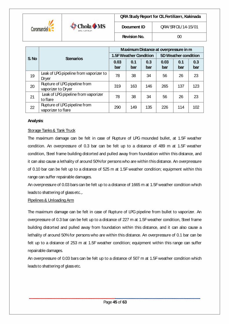
Table 8: Vapour cloud explosion results
S. No Scenarios
Maximum Distance at overpressure in m 1.5F Weather Condition 5D Weather condition
0.03 bar
0.1 bar
0.3 bar
0.03 bar
0.1 bar
0.3 bar
Storage Tanks & Tank Truck 1 Leak of LPG tank truck 103 51 45 77 38 34 2 Rupture of LPG tank truck 316 63 36 299 60 40 3 Leak of LPG mounded bullet NR NR NR NR NR NR 4 Rupture of LPG mounded bullet 1665 525 489 1640 442 405 5 Leak of LPG vaporizer 103 51 45 76 38 34 6 Rupture of LPG vaporizer 490 145 130 464 122 104
Pipelines & Unloading Arm
7 Leak of LPG unloading Hose / LPG Unloading Arm
38 15 12 NR NR NR
8 Rupture of LPG unloading Hose / LPG Unloading Arm
79 39 34 62 27 24
9 Leak of LPG Compressor suction line 33 14 12 NR NR NR
10 Rupture of LPG Compressor suction line
142 58 49 62 27 24
11 Leak of Compressor discharge line to tank truck
34 14 12 NR NR NR
12 Rupture of Compressor discharge line to tank truck
298 151 135 247 126 113
13 Leak of LPG pipeline from tank truck to bullet
40 15 13 NR NR NR
14 Rupture of LPG pipeline from tank truck to bullet
302 152 136 262 136 123
15 Leak of LPG pipeline from bullet to vaporizer
78 38 34 56 26 23
16 Rupture of LPG pipeline from bullet to vaporizer
507 253 227 442 225 203
17 Leak of LPG pipeline from vaporizer to boiler
78 38 34 56 26 23
18 Rupture of LPG pipeline from vaporizer to boiler
309 161 146 247 126 113
QRA Study Report for CIL Fertilizers, Kakinada
Document ID QRA/SR/CIL/14-15/01
Revision No. 00
Page 45 of 63
S. No Scenarios
Maximum Distance at overpressure in m 1.5F Weather Condition 5D Weather condition
0.03 bar
0.1 bar
0.3 bar
0.03 bar
0.1 bar
0.3 bar
19 Leak of LPG pipeline from vaporizer to Dryer
78 38 34 56 26 23
20 Rupture of LPG pipeline from vaporizer to Dryer
319 163 146 265 137 123
21 Leak of LPG pipeline from vaporizer to flare
78 38 34 56 26 23
22 Rupture of LPG pipeline from vaporizer to flare
290 149 135 226 114 102
Analysis:
Storage Tanks & Tank Truck
The maximum damage can be felt in case of Rupture of LPG mounded bullet, at 1.5F weather
condition. An overpressure of 0.3 bar can be felt up to a distance of 489 m at 1.5F weather
condition, Steel frame building distorted and pulled away from foundation within this distance, and
it can also cause a lethality of around 50% for persons who are within this distance. An overpressure
of 0.10 bar can be felt up to a distance of 525 m at 1.5F weather condition; equipment within this
range can suffer repairable damages.
An overpressure of 0.03 bars can be felt up to a distance of 1665 m at 1.5F weather condition which
leads to shattering of glass etc.,.
Pipelines & Unloading Arm
The maximum damage can be felt in case of Rupture of LPG pipeline from bullet to vaporizer. An
overpressure of 0.3 bar can be felt up to a distance of 227 m at 1.5F weather condition, Steel frame
building distorted and pulled away from foundation within this distance, and it can also cause a
lethality of around 50% for persons who are within this distance. An overpressure of 0.1 bar can be
felt up to a distance of 253 m at 1.5F weather condition; equipment within this range can suffer
repairable damages.
An overpressure of 0.03 bars can be felt up to a distance of 507 m at 1.5F weather condition which
leads to shattering of glass etc.

QRA Study Report for CIL Fertilizers, Kakinada
Document ID QRA/SR/CIL/14-15/01
Revision No. 00
Page 46 of 63
5.2.4. SUMMARY OF BLEVE
Table 9: BLEVE results
S. No Scenarios
Maximum Distance at overpressure in m 1.5F Weather Condition 5D Weather condition 0.03 bar
0.1 bar
0.3 bar
0.03 bar
0.1 bar
0.3 bar
Tank Truck 1 LPG tank truck 161.64 23.51 12.69 161.64 23.51 12.69
Analysis: The maximum damage can be felt in case of Rupture of LPG tank truck. An overpressure of 0.3 bar can be felt up to a distance of 12.69m, Steel frame building distorted and pulled away from foundation within this distance, and it can also cause a lethality of around 50% for persons who are within this distance. An overpressure of 0.10 bar can be felt up to a distance of 23.51 m; equipment within this range can suffer repairable damages.
An overpressure of 0.03 bars can be felt up to a distance of 161.64 m which leads to shattering of glass etc.,.
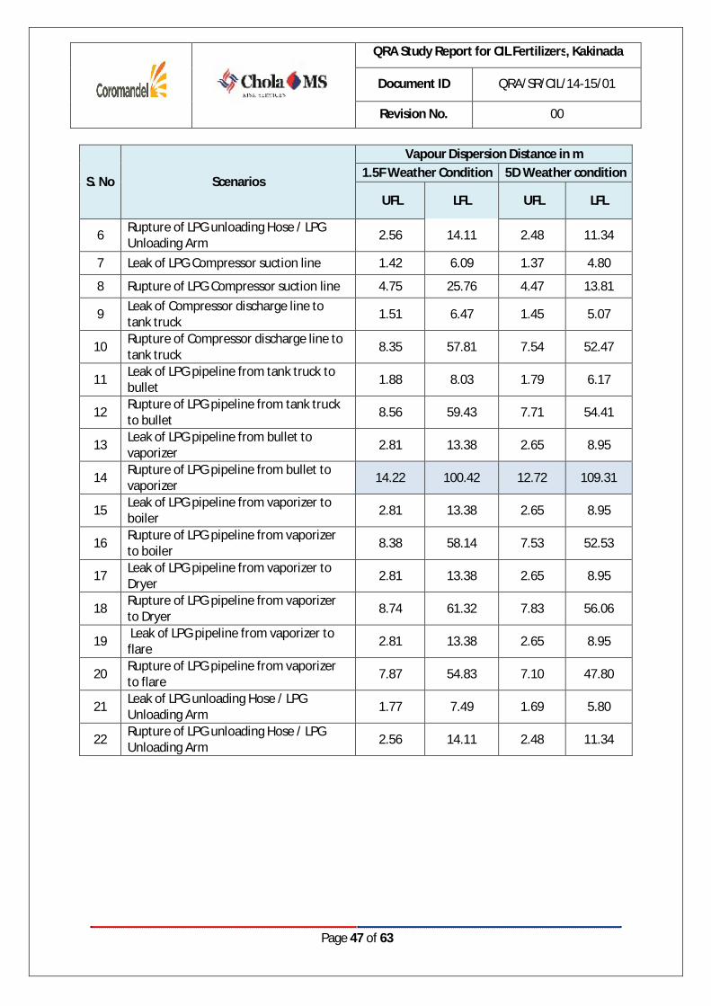
5.2.5. SUMMARY OF FLAMMABLE GAS DISPERSION
Table 10: Flammable gas dispersion results
S. No Scenarios
Vapour Dispersion Distance in m 1.5F Weather Condition 5D Weather condition
UFL LFL UFL LFL
Storage Tanks & Tank Truck 1 Leak of LPG tank truck 3.51 18.16 3.29 12.48
2 Rupture of LPG tank truck 4.98 10.12 5.42 17.96
3 Leak of mounded LPG bullet 4.56 11.44 3.40 6.55
4 Rupture of LPG mounded bullet 29.91 203.89 42.00 324.32
5 Leak of LPG vaporizer 3.50 18.11 3.28 12.45
6 Rupture of LPG vaporizer 10.73 90.61 7.84 52.92
Pipelines & Unloading Arm
5 Leak of LPG unloading Hose / LPG Unloading Arm 1.77 7.49 1.69 5.80
QRA Study Report for CIL Fertilizers, Kakinada
Document ID QRA/SR/CIL/14-15/01
Revision No. 00
Page 47 of 63
S. No Scenarios
Vapour Dispersion Distance in m 1.5F Weather Condition 5D Weather condition
UFL LFL UFL LFL
6 Rupture of LPG unloading Hose / LPG Unloading Arm 2.56 14.11 2.48 11.34
7 Leak of LPG Compressor suction line 1.42 6.09 1.37 4.80
8 Rupture of LPG Compressor suction line 4.75 25.76 4.47 13.81
9 Leak of Compressor discharge line to tank truck 1.51 6.47 1.45 5.07
10 Rupture of Compressor discharge line to tank truck 8.35 57.81 7.54 52.47
11 Leak of LPG pipeline from tank truck to bullet 1.88 8.03 1.79 6.17
12 Rupture of LPG pipeline from tank truck to bullet 8.56 59.43 7.71 54.41
13 Leak of LPG pipeline from bullet to vaporizer 2.81 13.38 2.65 8.95
14 Rupture of LPG pipeline from bullet to vaporizer 14.22 100.42 12.72 109.31
15 Leak of LPG pipeline from vaporizer to boiler 2.81 13.38 2.65 8.95
16 Rupture of LPG pipeline from vaporizer to boiler 8.38 58.14 7.53 52.53
17 Leak of LPG pipeline from vaporizer to Dryer 2.81 13.38 2.65 8.95
18 Rupture of LPG pipeline from vaporizer to Dryer 8.74 61.32 7.83 56.06
19 Leak of LPG pipeline from vaporizer to flare 2.81 13.38 2.65 8.95
20 Rupture of LPG pipeline from vaporizer to flare 7.87 54.83 7.10 47.80
21 Leak of LPG unloading Hose / LPG Unloading Arm 1.77 7.49 1.69 5.80
22 Rupture of LPG unloading Hose / LPG Unloading Arm 2.56 14.11 2.48 11.34

QRA Study Report for CIL Fertilizers, Kakinada
Document ID QRA/SR/CIL/14-15/01
Revision No. 00
Page 48 of 63
Analysis:
Storage Tanks, Tank Truck & Rail Wagon
In case of Rupture of Rupture of LPG mounded bullet, the LFL concentration is present up to a
maximum downwind distance of 324.32m at 5D weather condition and UFL concentration is present
up to a maximum distance of 42m at 5D weather condition. Presence of an ignition source may lead
to flash fire in this zone.
Pipelines, Unloading Arm & Hoses
In case of Rupture of Rupture of LPG pipeline from bullet to vaporizer, the LFL concentration is
present up to a maximum downwind distance of 109.31 m at 5D weather condition and UFL
concentration is present up to a maximum distance of 12.72 m at 5D weather condition. Presence of
an ignition source may lead to flash fire in this zone.
QRA Study Report for CIL Fertilizers, Kakinada
Document ID QRA/SR/CIL/14-15/01
Revision No. 00
Page 49 of 63
CHAPTER 6 RISK ANALYSIS

QRA Study Report for CIL Fertilizers, Kakinada
Document ID QRA/SR/CIL/14-15/01
Revision No. 00
Page 50 of 63
6.1. RISK PRESENTATION
Individual Risk: The Individual Risk calculation can be done using the specific locations of the known sources at the
establishment. If the cloud is not ignited at the establishment, ignition is assumed to take place at
maximum cloud area, with cloud area defined as the foot-print of the cloud. If contour is not present
outside the establishment, e.g., the spill of a flammable liquid in a bund, and if the ignition does not
occur at the establishment, ignition is assumed not to take place.
Societal Risk: The Societal Risk calculation can be done using the specific locations of the known sources at the
establishment and outside the establishment. The distribution of ignition sources in the
establishment should be known or can be anticipated. If only a few (weak) ignition sources are
present, there is a probability that the ignition of the cloud will not occur.
For calculating the frequency to be applied for modeling the following factors are taken into
consideration and multiplied with the basic failure frequency to calculate the calculated failure
frequency:
1. Blocking systems : The blocking systems are used to limit the released quantity following a LOC. A blocking system
consists of a detection system (e.g. gas detection, hydrocarbon detection, etc combined with shut-
off valves). The shut-off valves can be closed automatically or manually. Blocking systems are further
classified into Automatic, semi-automatic and non-automated (Manual) system. Semi Automatic
blocking system has been considered for this study.
2. Fire suppression systems The fire protection systems and fire fighting facilities which are used to restrict fire, the various
factors affecting the fire protection systems are:
« Response effectiveness (i.e. the system is responsive to a specific scenario)
« On-line availability (i.e. the system is online at the time of the emergency)
« Operational reliability (the system functions properly at the time of emergency)
3. Human Intervention / Intervention by operators
4. Ignition probabilities
QRA Study Report for CIL Fertilizers, Kakinada
Document ID QRA/SR/CIL/14-15/01
Revision No. 00
Page 51 of 63
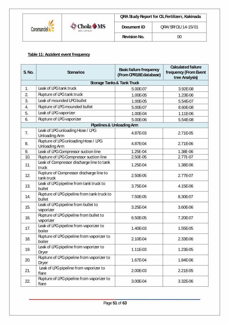
Table 11: Accident event frequency
S. No. Scenarios Basic failure frequency (From CPR18E database)
Calculated failure frequency (From Event
tree Analysis) Storage Tanks & Tank Truck
1. Leak of LPG tank truck 5.00E-07 3.92E-08 2. Rupture of LPG tank truck 1.00E-05 1.23E-06 3. Leak of mounded LPG bullet 1.00E-05 5.54E-07 4. Rupture of LPG mounded bullet 5.00E-07 8.60E-08 5. Leak of LPG vaporizer 1.00E-04 1.11E-06 6. Rupture of LPG vaporizer 5.00E-06 5.54E-08
Pipelines & Unloading Arm
7. Leak of LPG unloading Hose / LPG Unloading Arm 4.87E-03 2.71E-05
8. Rupture of LPG unloading Hose / LPG Unloading Arm 4.87E-04 2.71E-06
9. Leak of LPG Compressor suction line 1.25E-04 1.38E-06 10. Rupture of LPG Compressor suction line 2.50E-05 2.77E-07
11. Leak of Compressor discharge line to tank truck 1.25E-04 1.38E-06
12. Rupture of Compressor discharge line to tank truck 2.50E-05 2.77E-07
13. Leak of LPG pipeline from tank truck to bullet 3.75E-04 4.15E-06
14. Rupture of LPG pipeline from tank truck to bullet 7.50E-05 8.30E-07
15. Leak of LPG pipeline from bullet to vaporizer 3.25E-04 3.60E-06
16. Rupture of LPG pipeline from bullet to vaporizer 6.50E-05 7.20E-07
17. Leak of LPG pipeline from vaporizer to boiler 1.40E-03 1.55E-05
18. Rupture of LPG pipeline from vaporizer to boiler 2.10E-04 2.33E-06
19. Leak of LPG pipeline from vaporizer to Dryer 1.11E-03 1.23E-05
20. Rupture of LPG pipeline from vaporizer to Dryer 1.67E-04 1.84E-06
21. Leak of LPG pipeline from vaporizer to flare 2.00E-03 2.21E-05
22. Rupture of LPG pipeline from vaporizer to flare 3.00E-04 3.32E-06

QRA Study Report for CIL Fertilizers, Kakinada
Document ID QRA/SR/CIL/14-15/01
Revision No. 00
Page 52 of 63
Risk Summary
S. No. Scenarios Individual Risk per avg.
year Societal Risk per avg.
year Storage Tanks & Tank Truck
1. Leak of LPG tank truck 5.29E-10 4.97E-10 2. Rupture of LPG tank truck 1.24E-07 1.24E-07 3. Leak of mounded LPG bullet 3.61E-09 3.11E-09 4. Rupture of LPG mounded bullet 7.41E-07 7.98E-07 5. Leak of LPG vaporizer 9.75E-09 9.19E-09 6. Rupture of LPG vaporizer 2.22E-08 2.24E-08
Pipelines & Unloading Arm
7. Leak of LPG unloading Hose / LPG Unloading Arm 5.50E-08 5.12E-08
8. Rupture of LPG unloading Hose / LPG Unloading Arm 5.83E-09 5.06E-09
9. Leak of LPG Compressor suction line 1.33E-09 1.21E-09 10. Rupture of LPG Compressor suction line 8.02E-09 7.89E-09
11. Leak of Compressor discharge line to tank truck 1.93E-09 1.78E-09
12. Rupture of Compressor discharge line to tank truck 1.35E-08 1.32E-08
13. Leak of LPG pipeline from tank truck to bullet 9.90E-09 9.22E-09
14. Rupture of LPG pipeline from tank truck to bullet 5.89E-08 5.86E-08
15. Leak of LPG pipeline from bullet to vaporizer 2.01E-08 1.89E-08
16. Rupture of LPG pipeline from bullet to vaporizer 2.66E-07 2.68E-07
17. Leak of LPG pipeline from vaporizer to boiler 5.70E-07 7.02E-07
18. Rupture of LPG pipeline from vaporizer to boiler 3.13E-07 3.56E-07
19. Leak of LPG pipeline from vaporizer to Dryer 6.90E-08 6.51E-08
20. Rupture of LPG pipeline from vaporizer to Dryer 1.95E-07 2.22E-07
21. Leak of LPG pipeline from vaporizer to flare 1.23E-07 1.17E-07
22. Rupture of LPG pipeline from vaporizer to flare 3.36E-07 4.06E-07
Refer Annexure 2 for individual & societal risks for the above mentioned LOC scenarios.
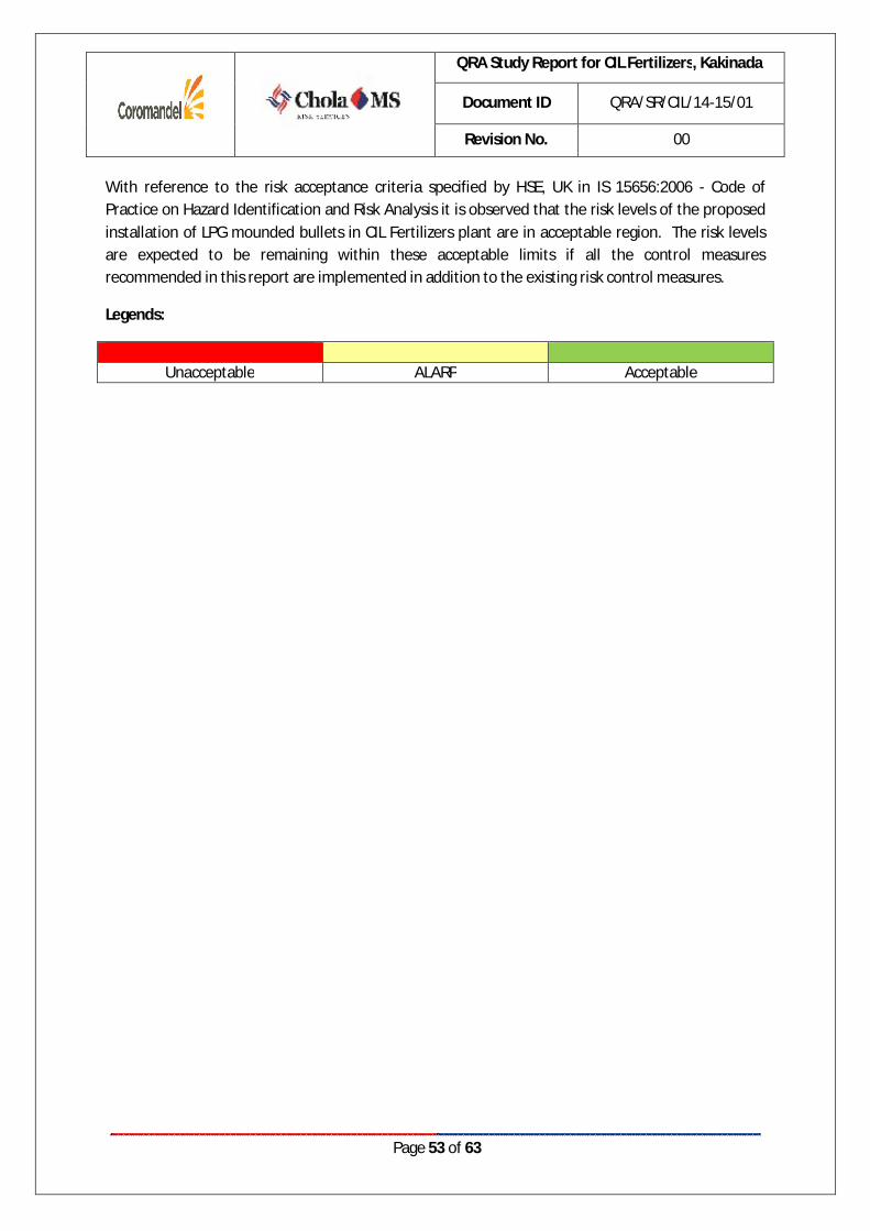
QRA Study Report for CIL Fertilizers, Kakinada
Document ID QRA/SR/CIL/14-15/01
Revision No. 00
Page 53 of 63
With reference to the risk acceptance criteria specified by HSE, UK in IS 15656:2006 - Code of Practice on Hazard Identification and Risk Analysis it is observed that the risk levels of the proposed installation of LPG mounded bullets in CIL Fertilizers plant are in acceptable region. The risk levels are expected to be remaining within these acceptable limits if all the control measures recommended in this report are implemented in addition to the existing risk control measures.
Legends:
Unacceptable ALARP Acceptable

QRA Study Report for CIL Fertilizers, Kakinada
Document ID QRA/SR/CIL/14-15/01
Revision No. 00
Page 54 of 63
CHAPTER 7 RISK CONTROL MEASURES

QRA Study Report for CIL Fertilizers, Kakinada
Document ID QRA/SR/CIL/14-15/01
Revision No. 00
Page 55 of 63
7.1. PROPOSED RISK CONTROL MEASURES AS PER PRE-FEASIBILITY
REPORT The following LPG safety systems will be considered while designing the storage facility:
1. Design and safety requirements for LPG mounded bullet are implemented as per OISD-Std-150.
2. LPG Mounded bullets are provided with necessary passive and active safety systems as per OISD-STD- 150 standard.
3. Fire Safe ROV will be provided on first flange on liquid line (s), vapour outlet and re-circulation lines from the vessel either from bottom or. No other flanges will be provided up to ROVs.
4. All vents and drains will be routed to an emergency flare system.
5. Minimum two different types of level indicators and one independent high level switch is proposed be provided.
6. Fire detectors based on heat detection through thermal fuses/quartz bulbs/ EP detectors will be provided.
7. At least four gas detectors will be installed and set for the 0.5*LEL (0.8%).
8. In the event of gas detection all ROVs on the affected vessel and LPG Pumps will trip.
9. Fire detector on each exposed portion of vessel will be installed; water sprinklers and deluge system will be automatically operated upon fire detection.
10. Water sprinklers/deluge system shall be provided for the LPG tank to avoid over heating of the content in case of small external jet fires.
11. At least one approved portable B:C rating dry chemical fire extinguisher may be installed near the tank
12. A warning sign or notice of minimum size of 800mm x 600mm shall be permanently and legibly displayed at the front of the installation.
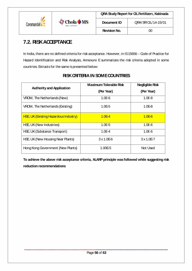
QRA Study Report for CIL Fertilizers, Kakinada
Document ID QRA/SR/CIL/14-15/01
Revision No. 00
Page 56 of 63
7.2. RISK ACCEPTANCE
In India, there are no defined criteria for risk acceptance. However, in IS 15656 – Code of Practice for
Hazard Identification and Risk Analysis, Annexure E summarizes the risk criteria adopted in some
countries. Extracts for the same is presented below:
RISK CRITERIA IN SOME COUNTRIES
Authority and Application Maximum Tolerable Risk
(Per Year)
Negligible Risk
(Per Year)
VROM, The Netherlands (New) 1.0E-6 1.0E-8
VROM, The Netherlands (Existing) 1.0E-5 1.0E-8
HSE, UK (Existing Hazardous Industry) 1.0E-4 1.0E-6
HSE, UK (New Industries) 1.0E-5 1.0E-6
HSE, UK (Substance Transport) 1.0E-4 1.0E-6
HSE, UK (New Housing Near Plants) 3 x 1.0E-6 3 x 1.0E-7
Hong Kong Government (New Plants) 1.00E-5 Not Used
To achieve the above risk acceptance criteria, ALARP principle was followed while suggesting risk
reduction recommendations

QRA Study Report for CIL Fertilizers, Kakinada
Document ID QRA/SR/CIL/14-15/01
Revision No. 00
Page 57 of 63
7.3. RISK CONTROL MEASURES SUGGESTED
The following risk control measures are recommended in addition to the existing risk control measures to maintain the risk levels within acceptable region:
SOP to address the operations pertaining to LPG receipt. Checklist to be prepared and records maintained for the same.
Fire water adequacy study to be carried out for the proposed LPG storage and handling facility
Integrity of the water sprinkler system pipeline to be ensured
Earthing /bonding of LPG handling pipelines to be periodically checked for integrity and continuity.
Onsite and offsite emergency response & disaster management plan should be developed for the proposed facility
OISD recommendations:
OISD-Std-150: Design and safety requirements for LPG mounded storage facility
High level alarm should be set at not more than 85% level of the volumetric capacity of the vessel.
LPG bullet should have at least two Safety Relief Valves (SRV). The full flow capacity of each SRV on mounded vessel(s) should be minimum 30 % of the capacity required for an
Unacceptable region
10-4 Per annum
Risk cannot be justified
The ALARP or tolerability Region (risk is undertaken Only if a benefit is Desired)
Tolerable only if further risk reduction is impractical, or the cost is not proportionate to the benefit gained
Broadly acceptable
Region
10-6 Per annum
Negligible risk
Risks closer to the unacceptable region merit a closer examination of potential risk reduction measures
QRA Study Report for CIL Fertilizers, Kakinada
Document ID QRA/SR/CIL/14-15/01
Revision No. 00
Page 58 of 63
equivalent size of above ground vessel. Suitable gas detectors should be placed at critical locations in the LPG storage area such as near the ROVs, in inspection tunnel, inside the nozzle box enclosure (if provided) or dome connection, near water draining/ sampling points.
Audio-visual alarms showing the location of gas leakage should be provided on the control panel. First level alarm shall be set at 20% of Lower Explosive Limit (LEL) and second level alarm at 60 % of LEL.
Cathodic protection system should be provided maintained and tested as per Annexure 1 of OISD-Std-150.
Sub-soil water, rainwater or any other surface water should not be allowed to percolate in to the mound.
Provision should be made to monitor the settlement of the mound/ vessel by providing permanent reference points. A minimum of three reference points shall be provided to ascertain uniform/ differential settlement and also identify possible vessel bending (One each near the vessel ends and one in the middle.)
In case of non-availability of flare system, the discharge from safety valve shall be vented vertically upwards to atmosphere without any intermediate valve on downstream side at an elevation of 3-meter (minimum) from the top of the mound or exposed nozzle whichever is higher for effective dispersion of hydrocarbons.
Hydrant (s)/monitor(s) should be located at a safe place and shall not be installed within 15 meters from the exposed portion facilities/equipment to be protected. Adequate coverage to unprotected portions exposed to thermal radiation including the top of the mound and product pipelines to be ensured.
Safety Relief valves should be tested and calibrated every year by a competent person.
Other OISD standards:
Periodical Inspection and thickness measurement are to be carried out for the storage tanks
Ensure that the Gas Monitoring System is calibrated and tested as per OISD-Std-153
Ensure fixed fire protection systems for the truck unloading area conforming to OISD-Std-117.
Inspection and Maintenance of Pipelines to be carried as per OISD 130. Following need to be adhered in terms of inspection frequency:
Pressure Testing – Once every year Painting – Once in 5 years External Inspection – Yearly
MB Lal Committee Recommendations:
SIL (Safety Integrity Level) of the tank level control must be improved and independent overfill protection meeting the requirement of Part 1 of EN 61511 shall be provided. Ensure that all the instruments in the level control loop are SIL rated.
QRA Study Report for CIL Fertilizers, Kakinada
Document ID QRA/SR/CIL/14-15/01
Revision No. 00
Page 59 of 63
Conclusion
If all the existing risk control measures along with the additional risk control measures recommended in this report are implemented, the risks levels of the proposed installation of LPG mounded bullets/its associated pipelines in CIL Fertilizers plant are observed to remain within acceptable region.
QRA Study Report for CIL Fertilizers, Kakinada
Document ID QRA/SR/CIL/14-15/01
Revision No. 00
Page 60 of 63
CHAPTER 8 REFERENCES
QRA Study Report for CIL Fertilizers, Kakinada
Document ID QRA/SR/CIL/14-15/01
Revision No. 00
Page 61 of 63
8.1. REFERENCES
« IS 15656:2006: Hazard identification and risk analysis - Code of Practice
« Guidelines for Quantitative Risk Assessment CPR 18E (Purple book), Committee for the
Prevention of Disasters, Netherlands (Edition: PGS 3, 2005)
« Guidelines for Hazard Evaluation Procedures - Centre for Chemical Process Safety, American
Institute of Chemical Engineers, New York, 1992.

QRA Study Report for CIL Fertilizers, Kakinada
Document ID QRA/SR/CIL/14-15/01
Revision No. 00
Page 62 of 63
CHAPTER 9 ANNEXURES
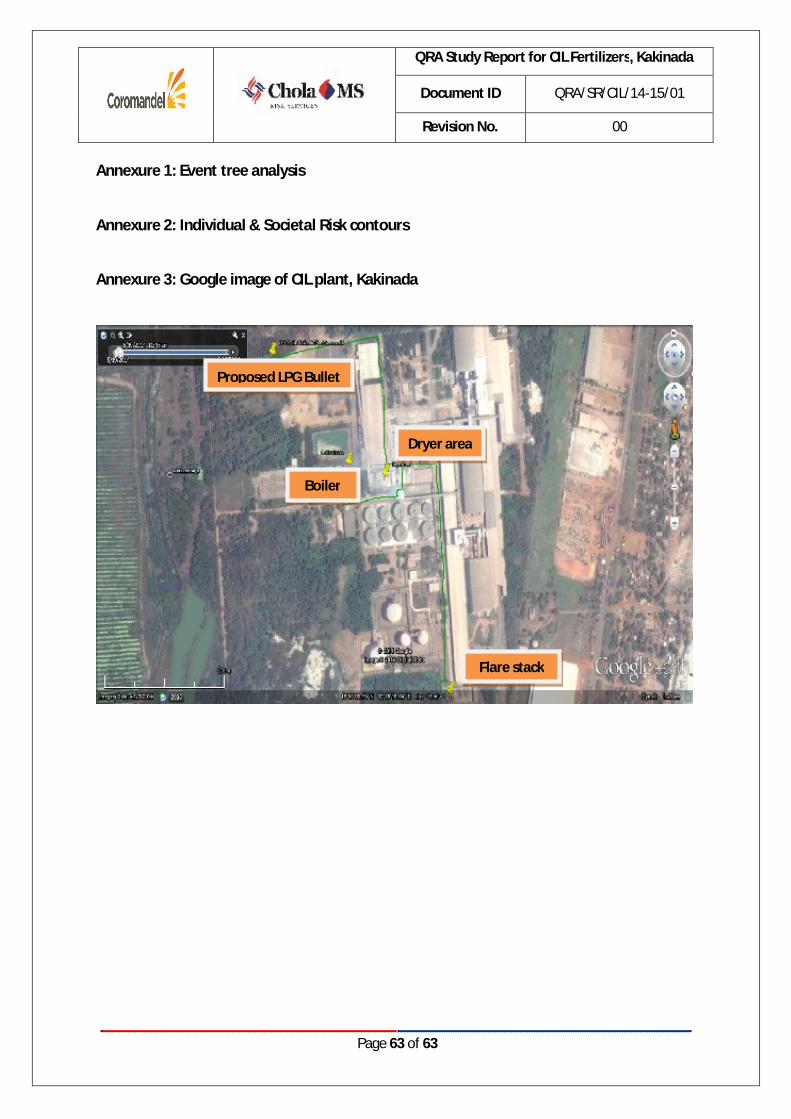
QRA Study Report for CIL Fertilizers, Kakinada
Document ID QRA/SR/CIL/14-15/01
Revision No. 00
Page 63 of 63
Annexure 1: Event tree analysis
Annexure 2: Individual & Societal Risk contours
Annexure 3: Google image of CIL plant, Kakinada
Proposed LPG Bullet
Dryer area
Boiler
Flare stack
QRA Study for CIL, Kakinada Page 1 of 23
ANNEXURE – 1: Event tree Analysis
Document : QRA Study for Coromandel International Limited,
Kakinada
Consultant : Cholamandalam Ms Risk Services Limited (CMSRSL)
Month/Year : December, 2014

QRA Study for CIL, Kakinada Page 2 of 23
1. Leak of LPG tank truck :( 10mm Leak)
Initiating Failure
Frequency
Immediate Ignition
Hydrocarbon Detection &
isolation
Fire protection system
Delayed Ignition
Explosion Probability
Event Outcome
Frequency
Yes
0.8 1.60E-08 Yes 0.04
No
0.2 4.00E-09
Yes 0.4 6.14E-09
5.00E-07 Yes
0.04
Success No 0.8 0.6 9.22E-09 No No 0.96 3.69E-07 0.96
Yes 0.4 1.54E-09 Yes 0.04 Failure No 0.2 0.6 2.30E-09 No 0.96 9.22E-08
Event Outcome
Controlled Jet/Pool Fire
Uncontrolled Jet/Pool Fire
VCE
Flash Fire Unignited Release
VCE Flash Fire Unignited Release

QRA Study for CIL, Kakinada Page 3 of 23
2. Rupture of LPG tank truck
Initiating Failure
Frequency
Immediate Ignition
Hydrocarbon Detection &
isolation
Fire protection system
Delayed Ignition
Explosion Probability
Event Outcome
Frequency
Yes
0.8 7.20E-07 Yes 0.09
No
0.2 1.80E-07
Yes 0.4 2.62E-07
1.00E-05 Yes
0.09
Success No 0.8 0.6 3.93E-07 No No 0.91 6.62E-06 0.91
Yes 0.4 6.55E-08 Yes 0.09 Failure No 0.2 0.6 9.83E-08 No 0.91 1.66E-06
Event Outcome
Controlled BLEVE/ Jet/Pool Fire
Uncontrolled BLEVE/Jet/Pool Fire
VCE
Flash Fire Unignited Release
VCE Flash Fire Unignited Release

QRA Study for CIL, Kakinada Page 4 of 23
3. Leak of LPG mounded bullet: 10mm Leak
Initiating Failure
Frequency
Immediate Ignition
Hydrocarbon Detection &
isolation
Fire protection system
Delayed Ignition
Explosion Probability
Event Outcome
Frequency
Yes
0.8 3.20E-07 Yes 0.04
No
0.2 8.00E-08
Yes 0.4 1.23E-07
1.00E-05 Yes
0.04
Success No 0.8 0.6 1.84E-07 No No 0.96 7.37E-06 0.96
Yes 0.4 3.07E-08 Yes 0.04 Failure No 0.2 0.6 4.61E-08 No 0.96 1.84E-06
Event Outcome
Controlled Pool/Jet Fire
Uncontrolled Pool/Jet Fire
VCE
Flash Fire Unignited Release
VCE Flash Fire Unignited Release
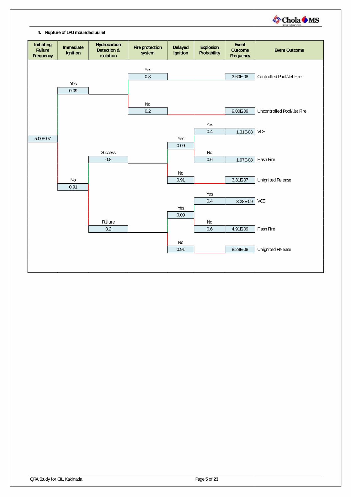
QRA Study for CIL, Kakinada Page 5 of 23
4. Rupture of LPG mounded bullet
Initiating Failure
Frequency
Immediate Ignition
Hydrocarbon Detection &
isolation
Fire protection system
Delayed Ignition
Explosion Probability
Event Outcome
Frequency
Yes
0.8 3.60E-08 Yes 0.09
No
0.2 9.00E-09
Yes 0.4 1.31E-08
5.00E-07 Yes
0.09
Success No 0.8 0.6 1.97E-08 No No 0.91 3.31E-07 0.91
Yes 0.4 3.28E-09 Yes 0.09 Failure No 0.2 0.6 4.91E-09 No 0.91 8.28E-08
Event Outcome
Controlled Pool/Jet Fire
Uncontrolled Pool/Jet Fire
VCE
Flash Fire Unignited Release
VCE Flash Fire Unignited Release

QRA Study for CIL, Kakinada Page 6 of 23
5. Leak of LPG vaporizer
Initiating Failure
Frequency
Immediate Ignition
Hydrocarbon Detection &
isolation
Fire protection system
Delayed Ignition
Explosion Probability
Event Outcome
Frequency
Yes
0.8 3.20E-06 Yes 0.04
No
0.2 8.00E-07
Yes 0.4 1.23E-06
1.00E-04 Yes
0.04
Success No 0.8 0.6 1.84E-06 No No 0.96 7.37E-05 0.96
Yes 0.4 3.07E-07 Yes 0.04 Failure No 0.2 0.6 4.61E-07 No 0.96 1.84E-05
Event Outcome
Controlled Pool/Jet Fire
Uncontrolled Pool/Jet Fire
VCE
Flash Fire Unignited Release
VCE Flash Fire Unignited Release

QRA Study for CIL, Kakinada Page 7 of 23
6. Rupture of LPG vaporizer
Initiating Failure
Frequency
Immediate Ignition
Hydrocarbon Detection &
isolation
Fire protection system
Delayed Ignition
Explosion Probability
Event Outcome
Frequency
Yes
0.8 1.60E-07 Yes 0.04
No
0.2 4.00E-08
Yes 0.4 6.14E-08
5.00E-06 Yes
0.04
Success No 0.8 0.6 9.22E-08 No No 0.96 3.69E-06 0.96
Yes 0.4 1.54E-08 Yes 0.04 Failure No 0.2 0.6 2.30E-08 No 0.96 9.22E-07
Event Outcome
Controlled Pool/Jet Fire
Uncontrolled Pool/Jet Fire
VCE
Flash Fire Unignited Release
VCE Flash Fire Unignited Release

QRA Study for CIL, Kakinada Page 8 of 23
7. Leak of LPG unloading Hose / LPG Unloading Arm
Initiating Failure
Frequency
Immediate Ignition
Hydrocarbon Detection &
isolation
Fire protection system
Delayed Ignition
Explosion Probability
Event Outcome
Frequency
Yes
0.8 7.79E-05 Yes 0.02
No
0.2 1.95E-05
Yes 0.4 3.05E-05
4.87E-03 Yes
0.02
Success No 0.8 0.6 4.58E-05 No No 0.98 3.74E-03 0.98
Yes 0.4 7.64E-06 Yes 0.02 Failure No 0.2 0.6 1.15E-05 No 0.98 9.35E-04
Event Outcome
Controlled Pool/Jet Fire
Uncontrolled Pool/Jet Fire
VCE
Flash Fire Unignited Release
VCE Flash Fire Unignited Release

QRA Study for CIL, Kakinada Page 9 of 23
8. Rupture of LPG unloading Hose / LPG Unloading Arm
Initiating Failure
Frequency
Immediate Ignition
Hydrocarbon Detection &
isolation
Fire protection system
Delayed Ignition
Explosion Probability
Event Outcome
Frequency
Yes
0.8 7.79E-06 Yes 0.02
No
0.2 1.95E-06
Yes 0.4 3.05E-06
4.87E-04 Yes
0.02
Success No 0.8 0.6 4.58E-06 No No 0.98 3.74E-04 0.98
Yes 0.4 7.64E-07 Yes 0.02 Failure No 0.2 0.6 1.15E-06 No 0.98 9.35E-05
Event Outcome
Controlled Pool/Jet Fire
Uncontrolled Pool/Jet Fire
VCE
Flash Fire Unignited Release
VCE Flash Fire Unignited Release
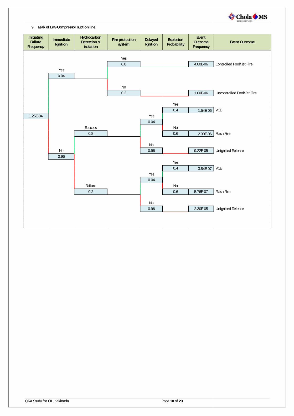
QRA Study for CIL, Kakinada Page 10 of 23
9. Leak of LPG Compressor suction line
Initiating Failure
Frequency
Immediate Ignition
Hydrocarbon Detection &
isolation
Fire protection system
Delayed Ignition
Explosion Probability
Event Outcome
Frequency
Yes
0.8 4.00E-06 Yes 0.04
No
0.2 1.00E-06
Yes 0.4 1.54E-06
1.25E-04 Yes
0.04
Success No 0.8 0.6 2.30E-06 No No 0.96 9.22E-05 0.96
Yes 0.4 3.84E-07 Yes 0.04 Failure No 0.2 0.6 5.76E-07 No 0.96 2.30E-05
Event Outcome
Controlled Pool/Jet Fire
Uncontrolled Pool/Jet Fire
VCE
Flash Fire Unignited Release
VCE Flash Fire Unignited Release

QRA Study for CIL, Kakinada Page 11 of 23
10. Rupture of LPG Compressor suction line
Initiating Failure Frequency
Immediate Ignition
Hydrocarbon Detection & isolation
Fire protection system
Delayed Ignition
Explosion Probability
Event Outcome Frequency
Yes
0.8 8.00E Yes 0.04
No
0.2 2.00E
Yes 0.4
2.50E-05 Yes
0.04
Success No 0.8 0.6 No No 0.96 1.84E 0.96
Yes 0.4 Yes 0.04 Failure No 0.2 0.6 1.15E No 0.96 4.61E
Event Outcome Frequency Event Outcome
8.00E-07 Controlled Pool/Jet Fire
2.00E-07 Uncontrolled Pool/Jet Fire
3.07E-07 VCE
4.61E-07 Flash Fire
1.84E-05 Unignited Release
7.68E-08 VCE
1.15E-07 Flash Fire
4.61E-06 Unignited Release

QRA Study for CIL, Kakinada Page 12 of 23
11. Leak of Compressor discharge line to tank truck
Initiating Failure
Frequency
Immediate Ignition
Hydrocarbon Detection &
isolation
Fire protection system
Delayed Ignition
Explosion Probability
Event Outcome
Frequency
Yes
0.8 4.00E-06 Yes 0.04
No
0.2 1.00E-06
Yes 0.4 1.54E-06
1.25E-04 Yes
0.04
Success No 0.8 0.6 2.30E-06 No No 0.96 9.22E-05 0.96
Yes 0.4 3.84E-07 Yes 0.04 Failure No 0.2 0.6 5.76E-07 No 0.96 2.30E-05
Event Outcome
Controlled Pool/Jet Fire
Uncontrolled Pool/Jet Fire
VCE
Flash Fire Unignited Release
VCE Flash Fire Unignited Release
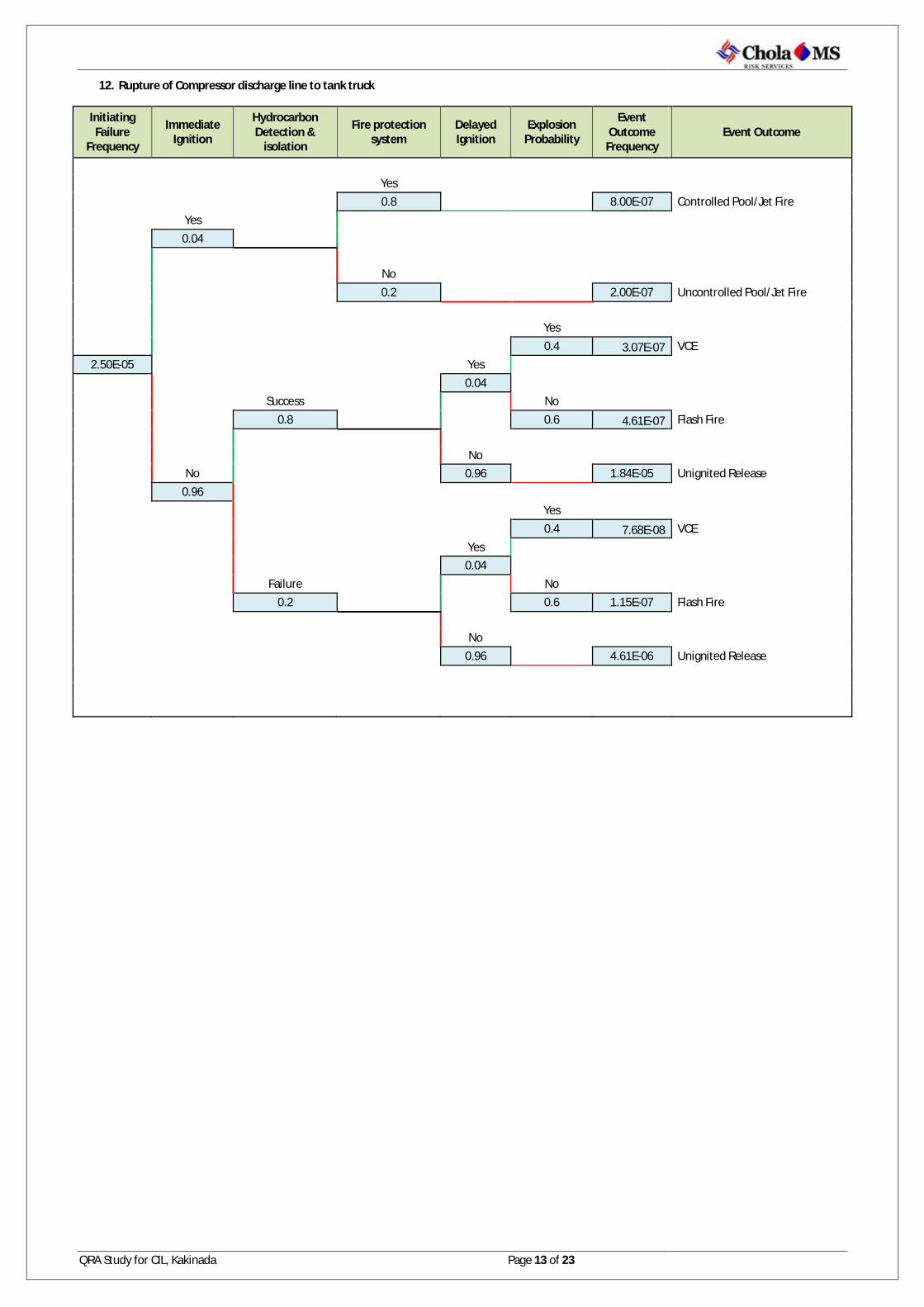
QRA Study for CIL, Kakinada Page 13 of 23
12. Rupture of Compressor discharge line to tank truck
Initiating Failure
Frequency
Immediate Ignition
Hydrocarbon Detection &
isolation
Fire protection system
Delayed Ignition
Explosion Probability
Event Outcome
Frequency
Yes
0.8 8.00E-07 Yes 0.04
No
0.2 2.00E-07
Yes 0.4 3.07E-07
2.50E-05 Yes
0.04
Success No 0.8 0.6 4.61E-07 No No 0.96 1.84E-05 0.96
Yes 0.4 7.68E-08 Yes 0.04 Failure No 0.2 0.6 1.15E-07 No 0.96 4.61E-06
Event Outcome
Controlled Pool/Jet Fire
Uncontrolled Pool/Jet Fire
VCE
Flash Fire Unignited Release
VCE Flash Fire Unignited Release

QRA Study for CIL, Kakinada Page 14 of 23
13. Leak of LPG pipeline from tank truck to bullet
Initiating Failure
Frequency
Immediate Ignition
Hydrocarbon Detection &
isolation
Fire protection system
Delayed Ignition
Explosion Probability
Event Outcome
Frequency
Yes
0.8 1.20E-05 Yes 0.04
No
0.2 3.00E-06
Yes 0.4 4.61E-06
3.75E-04 Yes
0.04
Success No 0.8 0.6 6.91E-06 No No 0.96 2.76E-04 0.96
Yes 0.4 1.15E-06 Yes 0.04 Failure No 0.2 0.6 1.73E-06 No 0.96 6.91E-05
Event Outcome
Controlled Pool/Jet Fire
Uncontrolled Pool/Jet Fire
VCE
Flash Fire Unignited Release
VCE Flash Fire Unignited Release

QRA Study for CIL, Kakinada Page 15 of 23
14. Rupture of LPG pipeline from tank truck to bullet
Initiating Failure
Frequency
Immediate Ignition
Hydrocarbon Detection &
isolation
Fire protection system
Delayed Ignition
Explosion Probability
Event Outcome
Frequency
Yes
0.8 2.40E-06 Yes 0.04
No
0.2 6.00E-07
Yes 0.4 9.22E-07
7.50E-05 Yes
0.04
Success No 0.8 0.6 1.38E-06 No No 0.96 5.53E-05 0.96
Yes 0.4 2.30E-07 Yes 0.04 Failure No 0.2 0.6 3.46E-07 No 0.96 1.38E-05
Event Outcome
Controlled Pool/Jet Fire
Uncontrolled Pool/Jet Fire
VCE
Flash Fire Unignited Release
VCE Flash Fire Unignited Release

QRA Study for CIL, Kakinada Page 16 of 23
15. Leak of LPG pipeline from bullet to vaporizer
Initiating Failure
Frequency
Immediate Ignition
Hydrocarbon Detection &
isolation
Fire protection system
Delayed Ignition
Explosion Probability
Event Outcome
Frequency
Yes
0.8 1.04E-05 Yes 0.04
No
0.2 2.60E-06
Yes 0.4 3.99E-06
3.25E-04 Yes
0.04
Success No 0.8 0.6 5.99E-06 No No 0.96 2.40E-04 0.96
Yes 0.4 9.98E-07 Yes 0.04 Failure No 0.2 0.6 1.50E-06 No 0.96 5.99E-05
Event Outcome
Controlled Pool/Jet Fire
Uncontrolled Pool/Jet Fire
VCE
Flash Fire Unignited Release
VCE Flash Fire Unignited Release

QRA Study for CIL, Kakinada Page 17 of 23
16. Rupture of LPG pipeline from vaporizer to boiler
Initiating Failure
Frequency
Immediate Ignition
Hydrocarbon Detection &
isolation
Fire protection system
Delayed Ignition
Explosion Probability
Event Outcome
Frequency
Yes
0.8 2.08E-06 Yes 0.04
No
0.2 5.20E-07
Yes 0.4 7.99E-07
6.50E-05 Yes
0.04
Success No 0.8 0.6 1.20E-06 No No 0.96 4.79E-05 0.96
Yes 0.4 2.00E-07 Yes 0.04 Failure No 0.2 0.6 3.00E-07 No 0.96 1.20E-05
Event Outcome
Controlled Pool/Jet Fire
Uncontrolled Pool/Jet Fire
VCE
Flash Fire Unignited Release
VCE Flash Fire Unignited Release

QRA Study for CIL, Kakinada Page 18 of 23
17. Leak of LPG pipeline from vaporizer to boiler
Initiating Failure
Frequency
Immediate Ignition
Hydrocarbon Detection &
isolation
Fire protection system
Delayed Ignition
Explosion Probability
Event Outcome
Frequency
Yes
0.8 4.48E-05 Yes 0.04
No
0.2 1.12E-05
Yes 0.4 1.72E-05
1.40E-03 Yes
0.04
Success No 0.8 0.6 2.58E-05 No No 0.96 1.03E-03 0.96
Yes 0.4 4.30E-06 Yes 0.04 Failure No 0.2 0.6 6.45E-06 No 0.96 2.58E-04
Event Outcome
Controlled Pool/Jet Fire
Uncontrolled Pool/Jet Fire
VCE
Flash Fire Unignited Release
VCE Flash Fire Unignited Release

QRA Study for CIL, Kakinada Page 19 of 23
18. Rupture of LPG pipeline from vaporizer to boiler
Initiating Failure
Frequency
Immediate Ignition
Hydrocarbon Detection &
isolation
Fire protection system
Delayed Ignition
Explosion Probability
Event Outcome
Frequency
Yes
0.8 6.72E-06 Yes 0.04
No
0.2 1.68E-06
Yes 0.4 2.58E-06
2.10E-04 Yes
0.04
Success No 0.8 0.6 3.87E-06 No No 0.96 1.55E-04 0.96
Yes 0.4 6.45E-07 Yes 0.04 Failure No 0.2 0.6 9.68E-07 No 0.96 3.87E-05
Event Outcome
Controlled Pool/Jet Fire
Uncontrolled Pool/Jet Fire
VCE
Flash Fire Unignited Release
VCE Flash Fire Unignited Release

QRA Study for CIL, Kakinada Page 20 of 23
19. Leak of LPG pipeline from vaporizer to Dryer
Initiating Failure
Frequency
Immediate Ignition
Hydrocarbon Detection &
isolation
Fire protection system
Delayed Ignition
Explosion Probability
Event Outcome
Frequency
Yes
0.8 3.55E-05 Yes 0.04
No
0.2 8.88E-06
Yes 0.4 1.36E-05
1.11E-03 Yes
0.04
Success No 0.8 0.6 2.05E-05 No No 0.96 8.18E-04 0.96
Yes 0.4 3.41E-06 Yes 0.04 Failure No 0.2 0.6 5.11E-06 No 0.96 2.05E-04
Event Outcome
Controlled Pool/Jet Fire
Uncontrolled Pool/Jet Fire
VCE
Flash Fire Unignited Release
VCE Flash Fire Unignited Release

QRA Study for CIL, Kakinada Page 21 of 23
20. Rupture of LPG pipeline from vaporizer to Dryer
Initiating Failure
Frequency
Immediate Ignition
Hydrocarbon Detection &
isolation
Fire protection system
Delayed Ignition
Explosion Probability
Event Outcome
Frequency
Yes
0.8 5.33E-06 Yes 0.04
No
0.2 1.33E-06
Yes 0.4 2.05E-06
1.67E-04 Yes
0.04
Success No 0.8 0.6 3.07E-06 No No 0.96 1.23E-04 0.96
Yes 0.4 5.11E-07 Yes 0.04 Failure No 0.2 0.6 7.67E-07 No 0.96 3.07E-05
Event Outcome
Controlled Pool/Jet Fire
Uncontrolled Pool/Jet Fire
VCE
Flash Fire Unignited Release
VCE Flash Fire Unignited Release

QRA Study for CIL, Kakinada Page 22 of 23
21. Leak of LPG pipeline from vaporizer to flare
Initiating Failure
Frequency
Immediate Ignition
Hydrocarbon Detection &
isolation
Fire protection system
Delayed Ignition
Explosion Probability
Event Outcome
Frequency
Yes
0.8 6.40E-05 Yes 0.04
No
0.2 1.60E-05
Yes 0.4 2.46E-05
2.00E-03 Yes
0.04
Success No 0.8 0.6 3.69E-05 No No 0.96 1.47E-03 0.96
Yes 0.4 6.14E-06 Yes 0.04 Failure No 0.2 0.6 9.22E-06 No 0.96 3.69E-04
Event Outcome
Controlled Pool/Jet Fire
Uncontrolled Pool/Jet Fire
VCE
Flash Fire Unignited Release
VCE Flash Fire Unignited Release
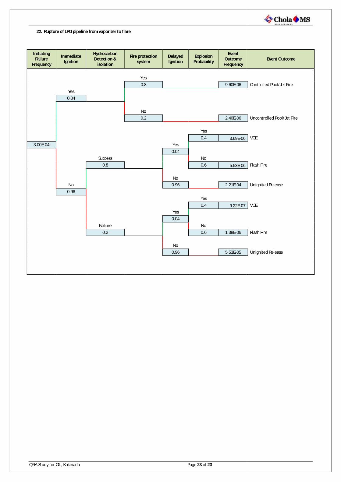
QRA Study for CIL, Kakinada Page 23 of 23
22. Rupture of LPG pipeline from vaporizer to flare
Initiating Failure
Frequency
Immediate Ignition
Hydrocarbon Detection &
isolation
Fire protection system
Delayed Ignition
Explosion Probability
Event Outcome
Frequency
Yes
0.8 9.60E-06 Yes 0.04
No
0.2 2.40E-06
Yes 0.4 3.69E-06
3.00E-04 Yes
0.04
Success No 0.8 0.6 5.53E-06 No No 0.96 2.21E-04 0.96
Yes 0.4 9.22E-07 Yes 0.04 Failure No 0.2 0.6 1.38E-06 No 0.96 5.53E-05
Event Outcome
Controlled Pool/Jet Fire
Uncontrolled Pool/Jet Fire
VCE
Flash Fire Unignited Release
VCE Flash Fire Unignited Release
QRA Study for CIL Page 1 of 23
ANNEXURE – 2: IR & SR CONTOURS
Document : QRA Study for Coromandel International Limited,
Kakinada
Consultant : Cholamandalam Ms Risk Services Limited (CMSRSL)
Month/Year : December, 2014

QRA Study for CIL Page 2 of 23
1. Leak of LPG tank truck
IR: 5.29E-10 per avg year
SR: 4.97E-10 per avg year
Considering the quantity of release, population distribution, weather condition & other process parameters Societal risk values for this scenario are negligible. Hence no FN curves are found.
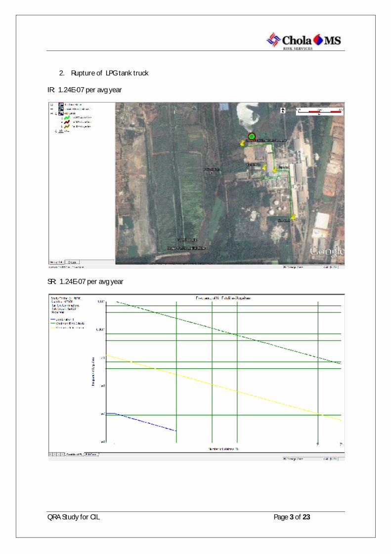
QRA Study for CIL Page 3 of 23
2. Rupture of LPG tank truck
IR: 1.24E-07 per avg year
SR: 1.24E-07 per avg year
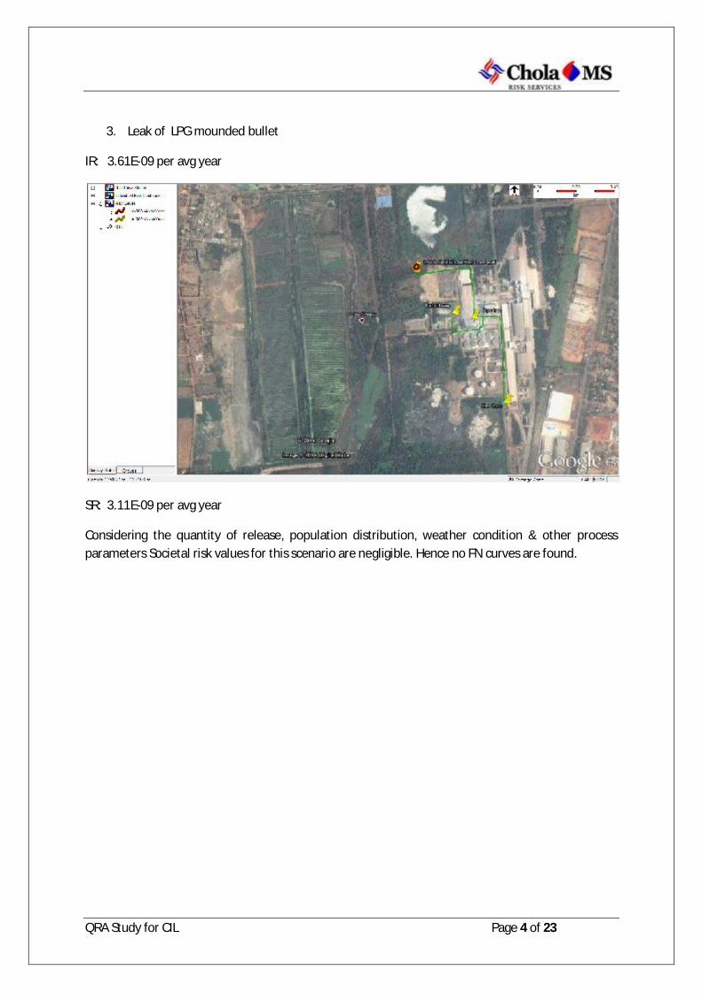
QRA Study for CIL Page 4 of 23
3. Leak of LPG mounded bullet
IR: 3.61E-09 per avg year
SR: 3.11E-09 per avg year
Considering the quantity of release, population distribution, weather condition & other process parameters Societal risk values for this scenario are negligible. Hence no FN curves are found.

QRA Study for CIL Page 5 of 23
4. Rupture of LPG mounded bullet
IR: 7.41E-07 per avg year
SR: 7.98E-07 per avg year
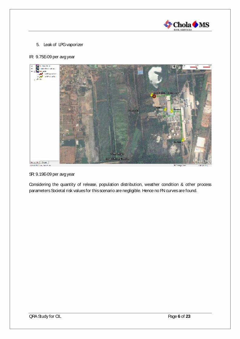
QRA Study for CIL Page 6 of 23
5. Leak of LPG vaporizer
IR: 9.75E-09 per avg year
SR: 9.19E-09 per avg year
Considering the quantity of release, population distribution, weather condition & other process parameters Societal risk values for this scenario are negligible. Hence no FN curves are found.
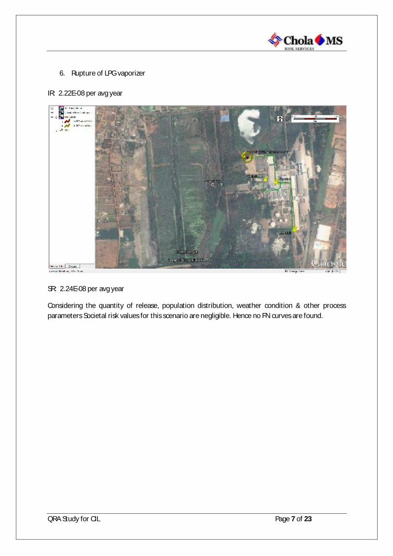
QRA Study for CIL Page 7 of 23
6. Rupture of LPG vaporizer
IR: 2.22E-08 per avg year
SR: 2.24E-08 per avg year
Considering the quantity of release, population distribution, weather condition & other process parameters Societal risk values for this scenario are negligible. Hence no FN curves are found.
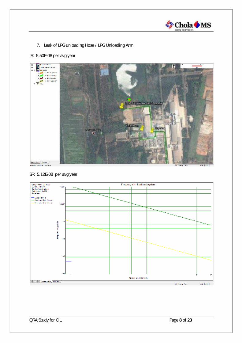
QRA Study for CIL Page 8 of 23
7. Leak of LPG unloading Hose / LPG Unloading Arm
IR: 5.50E-08 per avg year
SR: 5.12E-08 per avg year

QRA Study for CIL Page 9 of 23
8. Rupture of LPG unloading Hose / LPG Unloading Arm
IR: 5.10E-08 per avg year
SR: 5.10E-08 per avg year
Considering the quantity of release, population distribution, weather condition & other process parameters Societal risk values for this scenario are negligible. Hence no FN curves are found.

QRA Study for CIL Page 10 of 23
9. Leak of LPG Compressor suction line
IR: 1.33E-09 per avg year
SR: 1.21E-09 per avg year
Considering the quantity of release, population distribution, weather condition & other process parameters Societal risk values for this scenario are negligible. Hence no FN curves are found.

QRA Study for CIL Page 11 of 23
10. Rupture of LPG Compressor suction line
IR: 8.02E-09 per avg year
SR: 7.89E-09 per avg year
Considering the quantity of release, population distribution, weather condition & other process parameters Societal risk values for this scenario are negligible. Hence no FN curves are found.

QRA Study for CIL Page 12 of 23
11. Leak of Compressor discharge line to tank truck
IR: 1.93E-09 per avg year
SR: 1.78E-09 per avg year
Considering the quantity of release, population distribution, weather condition & other process parameters Societal risk values for this scenario are negligible. Hence no FN curves are found.

QRA Study for CIL Page 13 of 23
12. Rupture of Compressor discharge line to tank truck
IR: 1.35E-08 per avg year
SR: 1.32E-08 per avg year
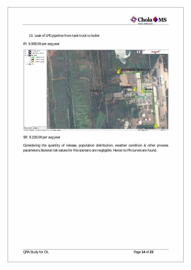
QRA Study for CIL Page 14 of 23
13. Leak of LPG pipeline from tank truck to bullet
IR: 9.90E-09 per avg year
SR: 9.22E-09 per avg year
Considering the quantity of release, population distribution, weather condition & other process parameters Societal risk values for this scenario are negligible. Hence no FN curves are found.
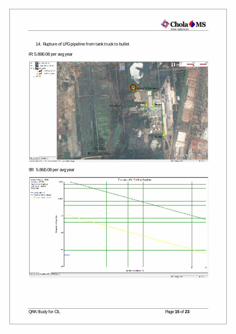
QRA Study for CIL Page 15 of 23
14. Rupture of LPG pipeline from tank truck to bullet
IR: 5.89E-08 per avg year
SR: 5.86E-08 per avg year

QRA Study for CIL Page 16 of 23
15. Leak of LPG pipeline from bullet to vaporizer
IR: 2.01E-08 per avg year
SR: 1.89E-08 per avg year
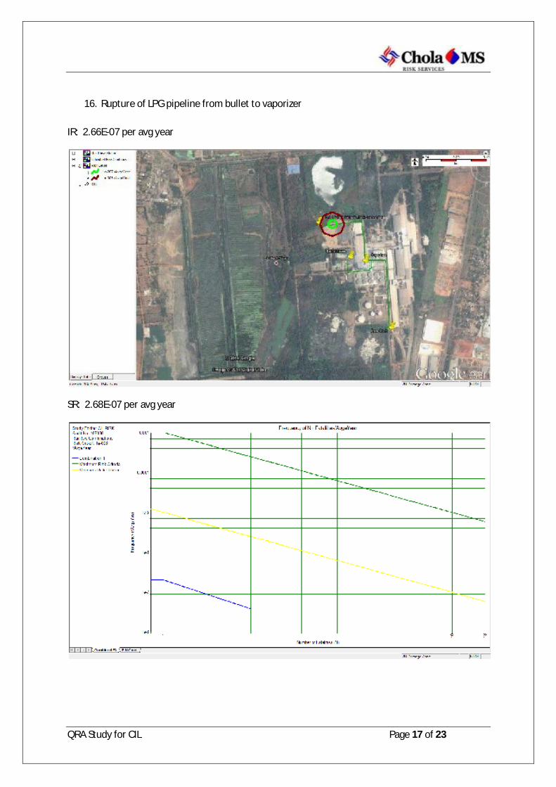
QRA Study for CIL Page 17 of 23
16. Rupture of LPG pipeline from bullet to vaporizer
IR: 2.66E-07 per avg year
SR: 2.68E-07 per avg year
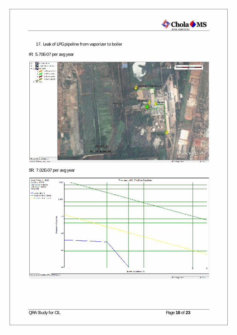
QRA Study for CIL Page 18 of 23
17. Leak of LPG pipeline from vaporizer to boiler
IR: 5.70E-07 per avg year
SR: 7.02E-07 per avg year

QRA Study for CIL Page 19 of 23
18. Rupture of LPG pipeline from vaporizer to boiler
IR: 3.13E-07 per avg year
SR: 3.56E-07 per avg year

QRA Study for CIL Page 20 of 23
19. Leak of LPG pipeline from vaporizer to Dryer
IR: 6.90E-08 per avg year
SR: 6.51E-08 per avg year

QRA Study for CIL Page 21 of 23
20. Rupture of LPG pipeline from vaporizer to Dryer
IR: 1.95E-07 per avg year
SR: 2.22E-07 per avg year

QRA Study for CIL Page 22 of 23
21. Leak of LPG pipeline from vaporizer to flare
IR: 1.23E-07 per avg year
SR: 1.17E-07 per avg year
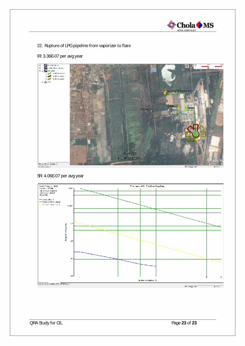
QRA Study for CIL Page 23 of 23
22. Rupture of LPG pipeline from vaporizer to flare
IR: 3.36E-07 per avg year
SR: 4.06E-07 per avg year