quantum cryptography for secure communication in ieee 802.11
TRANSCRIPT

Quantum Cryptography for Secure Communication in
IEEE 802.11 Wireless Networks
Shirantha Wijesekera
Faculty of Information Sciences and Engineering
University of Canberra ACT 2601
A thesis submitted in fulfilment of the requirements of the
Degree of Doctor of Philosophy
June 2011

ii

iii
Abstract
IEEE 802.11 is the Wireless Local Area Networks (WLAN) standard developed by the IEEE
LAN/MAN Standards Committee. WLANs are increasingly deployed by businesses, government
and SOHO users as they offer many advantages to customers with mobility, flexibility and
convenience. Wi-Fi is a trademark of the Wi-Fi Alliance that has been used with certified
products that belong to a class of WLANs based on the IEEE 802.11 standards. WLANs have
become one of the widely used communication systems in the world. It is estimated that there are
over 4,00,000 hotspots and millions of Wi-Fi users across the world as of now.
Since there are no boundaries in wireless networks, they are more vulnerable to security
threats than their wired counterparts. It is possible for an attacker to snoop on confidential
communications or modify them to gain access to the wireless networks more easily. Therefore,
providing secure communication for wireless networks has become one of the prime concerns.
IEEE has made amendments to the initial release of 802.11 standard with the 2004 release of
802.11i, since the former version was found to having security weaknesses in the way it handles
authentication and privacy.
Quantum Key Distribution (QKD), based on quantum cryptography, offers the promise of
unconditional security. QKD enables two parties to distribute a shared random bit string known
only to them, which can be used as a key to encrypt and decrypt messages.
This research implements a novel method of integrating QKD to distribute the secret key in
WLANs. IEEE 802.11i standard uses a 4 way handshake procedure to distribute the key used to
encrypt the data communication. In this research, instead of using the 4 way handshake
procedure, QKD based key distribution for IEEE 802.11 has been implemented targeting the
Counter mode with CBC-MAC Protocol (CCMP) of the Robust Security Network Association
(RSNA). Necessary communication flows of existing IEEE 802.11 protocol have been
indentified and modified. These modifications are done in such a way that only some of the
selected fields of the existing protocol have been used to carry QKD specific information.
Existing frame formats are not changed, keeping the overall modifications to a minimum. The

iv
resulting QKD based novel protocol offers unconditional security to the wireless networks with
the use of key distributed via QKD.
The key distribution process splits into two main communication channels. Firstly, it uses
quantum channel to transmit the photons where both parties interpret each photon to a bit (0 or 1)
depending on the bases and polarisation used. Secondly it uses classical channel, in this case it is
the existing wireless channel, to retrieve the final secured key.
Further, a number of possible extensions to IEEE 802.16 (WiMax) and also possibility of
merging with IEEE 802.21 standard are also discussed. Several possible enhancements of this
research are presented. One such enhancement is the use of Multi Agent Systems (MAS) to
deploy the same solution with better control and more efficiently.

vi

vii
Acknowledgements
First and foremost I would like to thank Associate Professor Xu Huang for supervision and
support over the course of my PhD program. His selfless perseverance, consistent attention to my
work and many insightful comments has been a great aid to me in completing this research. He
has been instrumental in providing me the guidance through his academic experience which was
always there when I needed. This research would never have taken shape without his support.
I would also like to express my humble gratitude to Professor Dharmendra Sharma for his
supervision, inspiration and kindness right throughout this research which has been invaluable to
me.
I am extremely grateful to my previous supervisors Assistant Professor Bala Balachandran, Dr
Sajal Palit, Dr Adrian Whichello for their support towards my studies.
I am indebted to emeritus Professor Paul Edwards for his supervision, enthusiasm and
inspiration given to me during the initial stage of this research. I would also like to thank him for
granting me CATQER top up scholarship.
I must also thank the IT support staff for their timely interventions to resolve my network
issues.
I am heartily thankful to administration staff of ISE, specially Serena Chong, Coral Suthern and
Kylie Reece for their support given to me in many ways.
I am grateful for University of Canberra for choosing me for a RTS scholarship, which was an
invaluable aid to me in completing my PhD.
Last, but not least, I would like to thank my wife and daughter for their support and
understanding right throughout the course of my studies.

viii

ix
List of Acronyms
ACK Acknowledgement
AES Advanced Encryption Standard
AK Authorisation Key
ANonce random or pseudo-random value generated by the Access Point
AP Access Point
APD Silicon Avalanche Photodiode
ARP Address Resolution Protocol
B92 QKD protocol developed by C. H. Bennett in 1992
BB84 QKD protocol developed by Bennett and Brassard 1984
BS Base Station
BSS Basic Service Set
CA Certificate Authority
CCMP Counter mode with CBC-MAC Protocol
CR Cognitive Radio
CTS Clear to Send
DES Data Encryption Standard
DoS Denial of Service
DS Distribution System
EAP-AKA EAP for UMTS Authentication and Key Agreement)
EAPOL Extensible Authentication Protocol over LAN
EAP-SIM EAP for GSM Subscriber Identity
EAP-TLS EAP Transport Layer Security
EAP-TTLS EAP-Tunnelled Transport Layer Security
ECC Elliptic Curve Cryptography
ESS Extended Service Set
GPRS General Packet Radio Service
GSM Global System for Mobile Communications
GTK Group Temporal Key
IBSS Independent Basic Service Set
IE Information Element
IEEE Institute of Electrical and Electronics Engineers

x
IPsec Internet Protocol Security
IV Initialization Vector
KCK Key Confirmation Key
KEK Key Encryption Key
L2TP Layer 2 Tunnelling Protocol
LEAP Lightweight Extensible Authentication Protocol
MAC Media Access Control
MAS Multi Agent System
MIC Message Integrity Check
MIMO Multiple-Input Multiple-Output
MLME MAC Sublayer Management Entity
NAT Network Address Translation
NIC Network Interface Controller
P2P Peer to Peer
PHY Physical layer
PKC Public Key Cryptography
PKI Public Key Infrastructure
PKM Privacy Key Management
PMK Pairwise Master Key
PPTP Point-to-Point Tunnelling Protocol
PRF Pseudo Random Function
PTK Pairwise Transient Key
QBER Quantum Bit Error Rate
QKD Quantum Key Distribution
Q-Key Quantum Key
Qubit Quantum Bit
RADIUS Remote Authentication Dial In User Service
RSA Rivest-Shamin-Adleman
RSN Robust Security Networks
RSNA Robust Security Network Association
RTS Request to Send
SAID Security Association IDs
SARG04 QKD protocol (derived from BB84)

xi
SNonce random or pseudo-random value generated by the Station
SS Subscriber Station
SSID Service Set Identifier
SSL Secure Sockets Layer protocol
TEK Traffic Encryption Keys
TK Temporal Key
TKIP Temporal Key Integrity Protocol
TSN Transition Security Network
UMTS Universal Mobile Telecommunications System
VoIP Voice over IP
VPN Virtual Private Network
WEP Wired Equivalent Privacy
Wi-Fi Wireless Fidelity
WiMAX Worldwide Interoperability for Microwave Access
WLAN Wireless Local Area Networks
WMAN Wireless Metropolitan area networks
WPA Wi-Fi Protected Access
WPA2 Wi-Fi Protected Access 2
WPAN Wireless Personal Area Networks

xii

xiii
Nomenclature:
• IEEE 802.1X standard provides authentication mechanism to clients accessing the IEEE
802.11 wireless network. IEEE 802.1X uses three main parties of its architecture:
Authenticator, Supplicant and Authentication Server. These entities have been referred to
in the network documentation by various other terms as well.
Widely used terms for the Authenticator are: Access Point (AP), Base Station (BS) etc.
Widely used terms for the Supplicant are: Station (STA), Client, Subscriber Station (SS)
etc.
For consistency, throughout this thesis, these entities have been referred as AP
(Authenticator) and STA (Supplicant).
Also for simplicity, the functionalities of the Authentication Server has been assumed to
be implemented within the AP.
• Wi-Fi is the industry standard for products as defined by the Wi-Fi Alliance and
conforming to IEEE 802.11 standard. Because of the relationship with the underlying
standards, the term Wi-Fi is often used as a synonym for IEEE 802.11 technology.
Further IEEE 802.11i standard specifies security mechanisms for wireless networks done
as an amendment to the original IEEE 802.11. Throughout this thesis, the term Wi-Fi has
also been referred as IEEE 802.11 and IEEE 802.11i.
.

xiv

xv
Table of Contents
Abstract ....................................................................................................................................... iii
Certificate of Authorship of Thesis .............................................................................................. v
Acknowledgements .................................................................................................................... vii
List of Acronyms .......................................................................................................................... ix
Table of Contents ....................................................................................................................... xv
List of Tables .............................................................................................................................. xxi
List of Figures ............................................................................................................................xxiii
Chapter 1 Introduction ........................................................................................................... 1
1.1 Motivation of the research ............................................................................................ 1
1.2 Wireless Networks ......................................................................................................... 2
1.3 Cryptography ................................................................................................................. 5
1.4 Secret Key and Public Key systems ................................................................................ 7
1.5 Quantum Cryptography ................................................................................................. 8
1.6 Why 802.11 Wireless Networks? ................................................................................... 9
1.6.1 Security issues in WEP .......................................................................................... 10
1.6.2 The 802.11i Standard ............................................................................................ 11
1.7 Research problems and proposed methodology ........................................................ 12
1.8 Experimental Procedure .............................................................................................. 13
1.9 Specific Contributions of the research......................................................................... 14
1.10 Structure of the thesis ................................................................................................. 15
Chapter 2 Research Content: A Survey ................................................................................ 17
2.1 802.11 Network Architecture ...................................................................................... 17

xvi
2.2 Security in 802.11 Networks ........................................................................................ 21
2.3 IEEE 802.11i Standard .................................................................................................. 22
2.3.1 Management Frames impacted by proposed modifications ............................... 22
2.3.2 RSNA Key Hierarchy .............................................................................................. 32
2.3.3 4-Way Hand Shake Protocol ................................................................................. 34
2.3.4 Security Issues in 4-Way Hand Shake Protocol .................................................... 35
2.4 802.1X Port Based Network Access Control ................................................................ 35
2.4.1 IEEE 802.1X Authentication .................................................................................. 36
2.4.2 EAPOL-Key frames ................................................................................................ 38
2.5 Use of EAP methods for Mutual Authentication ......................................................... 40
2.6 One-Time Pad ............................................................................................................... 42
2.7 Use of Virtual Private Network in Wi-Fi Networks ...................................................... 42
2.8 Security Improvements of IEEE 802.11 Networks ....................................................... 44
2.9 Quantum Cryptography ............................................................................................... 45
2.9.1 Quantum Bit Error Rate of Quantum Channel ..................................................... 47
2.9.2 Quantum Key Distribution .................................................................................... 48
2.9.3 Probability of Errors Introduced by Eavesdropping ............................................. 55
2.9.4 QKD Protocols and Networks ............................................................................... 56
2.9.5 Attacks on quantum cryptography networks ....................................................... 57
Chapter 3 Methodology ........................................................................................................ 59
3.1 Classical Cryptography vs. Quantum Cryptography .................................................... 59
3.2 Advantages of using QKD in 802.11 networks ............................................................. 60
3.3 QKD Based Solution for Key Distribution in Wi-Fi ....................................................... 61

xvii
3.3.1 Proposed protocol ................................................................................................ 61
3.3.2 STA State transition diagrams .............................................................................. 68
3.3.3 STA EAPOL Frame Pseudo-codes .......................................................................... 72
3.3.4 AP State transition diagrams ................................................................................ 75
3.3.5 EAPOL Frame Pseudo-codes for AP ...................................................................... 79
3.3.6 Packet Level Changes ........................................................................................... 82
3.3.7 Quantum communication channel ....................................................................... 97
Chapter 4 Implementation ................................................................................................... 99
4.1 Implementation of Quantum Channel ......................................................................... 99
4.2 Implementation of Wireless Channel ........................................................................ 104
4.3 Simulink Approach ..................................................................................................... 106
4.3.1 QKD Software Implementation .......................................................................... 107
4.4 Full Model of the System ........................................................................................... 123
Chapter 5 Evaluation of Results ......................................................................................... 125
5.1 Analysis of Sifting Phase ............................................................................................. 127
5.2 Analysis of Error Estimation ....................................................................................... 130
5.2.1 Error Estimation – Successful Scenario .............................................................. 132
5.2.2 Error Estimation – Unsuccessful Scenario .......................................................... 134
5.2.3 Improved Error Estimation for Wireless QKD..................................................... 135
5.3 Analysis of Reconciliation .......................................................................................... 138
5.3.1 Performance of Proposed Bisect Reconciliation Protocol.................................. 144
5.4 Analysis of Privacy Amplification ............................................................................... 145
5.5 Analysis of Overall QKD based Wi-Fi Protocol ........................................................... 147

xviii
5.6 Analysis of the Quantum Channel ............................................................................. 151
5.7 Summary .................................................................................................................... 152
Chapter 6 Multi Agents for QKD in 802.11 Networks ........................................................ 153
6.1 Why Multi Agent System? ......................................................................................... 153
6.2 QKD based Multi Agent System Approach ................................................................ 155
6.2.1 The Operational Procedure ................................................................................ 158
6.3 Implementation of MAS Solution .............................................................................. 161
6.4 Adding intelligent behaviour ..................................................................................... 164
6.4.1 Possible Attacks on 802.11 and 802.1X Protocol Standards .............................. 164
6.4.2 How to use Agents to detect attacks.................................................................. 166
6.5 Future Work of MAS approach .................................................................................. 167
6.5.1 Implement the Intelligence to detect attacks .................................................... 168
6.5.2 Extending to Support Multiple EAP types .......................................................... 168
6.5.3 Extending to Support Multiple QKD Protocols ................................................... 169
6.5.4 Use of Mobile Agents for Wider Coverage ......................................................... 170
6.5.5 Communication between agents ....................................................................... 171
6.6 Summary of MAS Approach ....................................................................................... 174
Chapter 7 Conclusion and Future Work ............................................................................. 177
7.1 Use of One Key for Multiple Sessions ........................................................................ 181
7.2 Multi Agent Solution .................................................................................................. 183
7.3 Overcoming Line-of-Sight Issues ................................................................................ 184
7.3.1 Use of MIMO Technology ................................................................................... 184
7.3.2 Use of Cognitive Radio Communications ........................................................... 185

xix
7.3.3 Other Solutions for Line-of-Sight ........................................................................ 186
7.4 Use of Virtual Private Network in Wi-Fi Networks .................................................... 186
7.5 Extending QKD for WiMAX ........................................................................................ 187
7.5.1 WiMAX Security .................................................................................................. 188
7.5.2 Security issues with WiMAX ............................................................................... 192
7.5.3 Use of QKD for Key Distribution in WiMAX ........................................................ 193
7.6 Universal Architecture for Key Distribution in Wireless Networks ........................... 194
7.7 Achievements and Contributions against research questions .................................. 195
Bibliography.............................................................................................................................. 197
Appendices A: Research Papers Published .............................................................................. 213
Appendices B: Patents Granted ............................................................................................... 215
Appendices D: Universal Hash Function .................................................................................. 217

xx

xxi
List of Tables
Table 1 : Wireless Networks - A Comparison ................................................................................................................. 4
Table 2 : Beacon Frame Body [56] ............................................................................................................................... 24
Table 3 : Probe Request Frame Body [56] .................................................................................................................... 25
Table 4 : Probe Response Frame Body [8] ................................................................................................................... 26
Table 5 : Element IDs [56] ............................................................................................................................................ 29
Table 6 : Association Request Frame Body [56] ........................................................................................................... 30
Table 7 : Association Response Frame Body [8]........................................................................................................... 30
Table 8 : Reassociation Request Frame Body [8] ......................................................................................................... 31
Table 9 : Reassociation Response Frame Body [8] ....................................................................................................... 32
Table 10 : Beacon Frame Body (only the first 10 fields are shown) ............................................................................. 84
Table 11 : New Element IDs for QKD ............................................................................................................................ 86
Table 12 : Reconciliation parity check EAPOL frame details ........................................................................................ 93
Table 13 : Bases Representation in STA Buffer .......................................................................................................... 103
Table 14 : Bits available to recover the final key after removing errors .................................................................... 127
Table 15 : Time taken (ms) to complete Sifting phase for various error rates .......................................................... 129
Table 16 : Summary of Polarised Photon Propagation Trial Data [27]....................................................................... 131
Table 17 : Time taken to complete Error Estimation – Successful Scenario .............................................................. 133
Table 18 : Time taken to complete Error Estimation – Unsuccessful Scenario .......................................................... 135
Table 19 : Time Taken for Reconciliation for Block Size 8 .......................................................................................... 140
Table 20 : Total time for proposed protocol (Error Rate=10%, Initial Block size=8 bits) ........................................... 148
Table 21 : Total time for proposed protocol (Error Rate=20%, Initial Block size=8 bits) ........................................... 148
Table 22 : Total time for proposed protocol (Error Rate=10%, Initial Block size=16 bits) ......................................... 149
Table 23 : Total time for proposed protocol (Error Rate=20%, Initial Block size=16 bits) ......................................... 149

xxii

xxiii
List of Figures
Figure 1 : ESS Architecture [1] ...................................................................................................................................... 18
Figure 2 : Relationship between state variables and services [1] ................................................................................ 20
Figure 3 : Capability information field [8] .................................................................................................................... 25
Figure 4 : Request Information element [1] ................................................................................................................. 27
Figure 5 : Information Element Format [1] .................................................................................................................. 28
Figure 6 : Pairwise Key Hierarchy of IEEE 802.11i of CCMP [30] .................................................................................. 33
Figure 7 : 4-Way Handshake [5] ................................................................................................................................... 34
Figure 8 : IEEE 802.1X Authentication [34] .................................................................................................................. 37
Figure 9 : EAPOL-Key Frame [8] ................................................................................................................................... 39
Figure 10 : Key Information bit layout [8] .................................................................................................................... 39
Figure 11 : Polarisation by Filters [144]........................................................................................................................ 46
Figure 12 : Quantum Communication Setup [6] .......................................................................................................... 49
Figure 13 : Example of Key Recovery of QKD Protocol ................................................................................................ 50
Figure 14 : Simplified diagram of final key retrieval .................................................................................................... 55
Figure 15 : The Proposed QKD Based Wi-Fi Protocol [6] .............................................................................................. 63
Figure 16 : Successful Error Estimation Communication Flow ..................................................................................... 65
Figure 17 : Unsuccessful Error Estimation Communication Flow ................................................................................ 66
Figure 18 : RSNA STA key management state machine – QKD Phase .......................................................................... 69
Figure 19 : RSNA AP key management state machine (QKD Phase) – Part 1 ............................................................... 76
Figure 20 : AP State Machine (QKD Phase) - Part 2...................................................................................................... 77
Figure 21 : Modified Capability information field of Beacon ....................................................................................... 84
Figure 22 : QKD Parameters Element Format .............................................................................................................. 86
Figure 23 : Modified EAPOL-Key Frame to implement QKD [6] ................................................................................... 89
Figure 24 : Modified Key Information bit layout .......................................................................................................... 90
Figure 25 : Key Data field values of EAPOL frame during reconciliation phase of QKD ............................................... 92
Figure 26 : Example of reconciliation via EAPOL (where; A = AP, S = STA) .................................................................. 93
Figure 27 : Key Data for block 6 ................................................................................................................................... 94
Figure 28 : Reconciliation Process using Parity Check ................................................................................................. 96
Figure 29 : High Level Set Up of Quantum Channel [10] ............................................................................................ 100
Figure 30 : Schematic Diagram of QKD System [19], [30] .......................................................................................... 101
Figure 31 : QKD Experimental Setup .......................................................................................................................... 104
Figure 32 : C++ Class Structure of AP ......................................................................................................................... 109

xxiv
Figure 33 : C++ Class Structure of STA ....................................................................................................................... 111
Figure 34 : Simulink Model of Sifting Phase for Access Point .................................................................................... 113
Figure 35 : Main C++ Function used for Sifting Implementation at AP (scaled image) .............................................. 114
Figure 36 : Simulink Model of Sifting Phase for STA .................................................................................................. 115
Figure 37 : Simulink Model of Error Estimation Phase for STA .................................................................................. 116
Figure 38 : Simulink Model of Error Estimation Phase for AP .................................................................................... 117
Figure 39 : Simulink Model of Reconciliation Phase for Access Point ........................................................................ 118
Figure 40 : Simulink Model of Reconciliation Phase for STA ...................................................................................... 119
Figure 41 : Main C++ Function for Parity Check Algorithm (scaled image) ................................................................ 121
Figure 42 : Simulink Model of Privacy Amplification Phase for AP ............................................................................ 122
Figure 43 : Simulink Model of Privacy Amplification Phase for STA........................................................................... 122
Figure 44 : Full Simulink model of Access Point ......................................................................................................... 123
Figure 45: Full Simulink model of STA ........................................................................................................................ 124
Figure 46 : Communication Flows of Sifting Phase .................................................................................................... 128
Figure 47 : Time taken for Sifting phase .................................................................................................................... 129
Figure 48 : Error Estimation – Successful Scenario .................................................................................................... 132
Figure 49 : Time taken for Error Estimation ............................................................................................................... 133
Figure 50 : Estimation – Unsuccessful Scenario ......................................................................................................... 134
Figure 51 : Comparison of Traditional and Proposed Error Estimation ..................................................................... 138
Figure 52 : Key sizes Vs Time for block size = 8 .......................................................................................................... 141
Figure 53 : Time to complete Reconciliation for Key Length = 500 bits ..................................................................... 142
Figure 54 : Time to complete Reconciliation for Error Rate of 30% ........................................................................... 143
Figure 55 : Comparison of Traditional and Proposed Methods ................................................................................. 145
Figure 56 : Time taken for Privacy Amplification ....................................................................................................... 146
Figure 57 : The enterprise [3] ..................................................................................................................................... 156
Figure 58 : The Agent Society [3] ............................................................................................................................... 158
Figure 59 : The Process Flow of Wireless QKD [9]...................................................................................................... 160
Figure 60 : Architecture diagram of MAS Solution..................................................................................................... 161
Figure 61 : High level C++ class diagram of the MAS application .............................................................................. 162
Figure 62: Session Hijack by MAC address Spoofing .................................................................................................. 165
Figure 63 : Agent Architecture to Detect Attacks ...................................................................................................... 167
Figure 64 : The extended architecture to support multiple EAP types ...................................................................... 168
Figure 65 : Extended architecture to support multiple QKD Protocols ..................................................................... 169
Figure 66 : Modified Enterprise supporting multiple QKD protocols and EAP types ................................................. 170

xxv
Figure 67 : An example of KQML block for communication....................................................................................... 172
Figure 68 : Agent UML interactions of QKD ............................................................................................................... 173
Figure 69 : Scenario of One Quantum Key for Multiple Sessions .............................................................................. 182
Figure 70 : AK Management in BS and SS [85] ........................................................................................................... 190
Figure 71 : TEK management in BS and SS [85] .......................................................................................................... 191

xxvi

1
Chapter 1 Introduction
This chapter gives an introduction to the research and its associated protocols. In the overview
of the research, the main issues that motivated this research have been discussed. This research
work focus on security aspect of wireless networks, to be precise, WLANs defined under IEEE
802.11 standard. In addition, use of quantum cryptography to improve the key distribution of
WLANs is also discussed. The two technologies, WLANs and quantum cryptography are not
quite used together so far. This chapter also gives some basic introduction to quantum
cryptography with respect to improving the security.
An overview to the proposed methodology has also been discussed along with experimental
procedures, during which perceived contributions of the research is also summarized. This
chapter further extends to discuss what existed prior to the research and the achievements of the
research. Finally, how this thesis is structured into various chapters and brief introduction to each
chapter is also given. Number of research papers have been published on several related streams
[3], [5], [6], [7], [9], [10], [14], [16], [19], [26], [30], [31], [38], [125], [163], [165] including
four patents [47], [48], [49], [164].
1.1 Motivation of the research
Wireless communications are becoming ubiquitous in homes, offices and enterprises with
the ability to provide high-speed, high-quality information exchange between portable
devices such as computers, PDAs, IP phones etc. It brings great benefit in areas like
temporary installations, in buildings where wiring is logistically difficult, or in locations such
as college campuses or airports where users are not likely to do all of their computing in one
fixed spot. With the advancement of modern wireless technology, most people prefer to
avoid Ethernet cables to connect to computers. Nowadays, even certain emergency services
are transferring their confidential data through a wireless network. They provides great
convenience to the users, avoids excessive cabling, portability between different networks.

2
Businesses are also benefitted by wireless networks mainly due to easy data sharing, cheaper
equipment, cost reductions in operations and maintenance etc.
As the wireless communication has gone through rapid advancements during the last few
decades, an increasing number of government agencies, businesses and home users are either
using, or considering using, wireless technologies in their environments [40]. This justifies
the reason why wireless technology is overwhelmingly used in the communication industry
today.
While wireless networks and their applications are becoming popular every day, associated
security issues have become a great concern. Due to the nature of wireless communications,
it is possible for an adversary to snoop on confidential communications or modify them to
gain access to the wireless networks more easily than with wired networks.
The focus of this research is on improving the security of IEEE 802.11 networks through
secure key distribution. Due to the nature of the limited coverage offered by 802.11 wireless
networks, it was found that the key exchange can be done securely with the use of quantum
cryptography. It was found that from the laws of physics, Quantum Key Distribution (QKD)
offers unconditional security between two communication parties [69]. This research work
explores the use of QKD with the existing 802.11i Wi-Fi networks to obtain secured data
communications. This research presents a novel wireless protocol with the use of QKD to
implementation key distribution in 802.11i networks.
1.2 Wireless Networks
Wireless technology is rapidly evolving, and is playing an increasing role in the lives of
people throughout the world. In addition, ever-larger numbers of people are relying on the
technology directly or indirectly. The wireless communication revolution made integrated
networks a reality by bringing fundamental changes to networking and telecommunication.
By freeing the user from the cord, cellular systems, personal communications networks,
wireless LAN's and mobile radio networks harbor the promise of fully distributed mobile
computing and communications extended to anytime, anywhere. Wireless networks have
continued to develop and their uses have grown significantly across many areas including

3
businesses, education, entertainment, defence etc. Wireless networks provide a fairly
inexpensive and rapid way to be connected to the internet via satellites, radio or by other
means to countries and regions where the telecom infrastructure is poor or lacks resources.
People and businesses use wireless networks to send and share data quickly whether it be in a
small office building or across the world.
With the advancements in wireless technology in recent years, the number of mobile
phones and wireless internet users has increased significantly. The technology promises to
increase the speed and range of wireless networks even further, bringing the benefits of
wireless computing to an ever greater number of people and expanding the power of these
networks to accommodate video and other bandwidth intensive applications. Wireless
technology has literally changed our lives. Many of us cannot imagine a day without using a
wireless device. In fact, we use them so much, that we barely recognize them as wireless
anymore.
There are several types of wireless networks exist as of now. They can be divided into
three main categories in terms of their coverage:
• Wireless Local Area Networks (WLAN)
• Wireless Metropolitan area networks (WMAN)
• Wireless Personal Area Networks (WPAN)
WPANs is used to interconnect devices within a relatively small coverage area. Some
widely used WPAN protocols are Bluetooth and ZigBee. Bluetooth facilitates exchanging
data over short distances from fixed and mobile devices. ZigBee is a specification for a suite
of high level communication protocols using small, low-power digital radios based on the
IEEE 802.15.4-2006 standard [151].
Like WPANs, WLAN also cater to interconnect devices within small indoor coverage
areas such as a home, office, or university. Wireless LANs are standardized under the IEEE
802.11 series. Most widely used WLAN is Wi-Fi (Wireless Fidelity). Wi-Fi is a commonly
used wireless network in computer systems to enable connection to the internet or other
devices that have Wi-Fi functionalities. Wi-Fi networks broadcast radio waves that can be
4
picked up by Wi-Fi receivers attached to different computers or mobile phones. Another well
known WLAN is Fixed Wireless Data network which provides point to point links between
computers or networks at two locations, often using dedicated microwave, infrared or laser
beams over line-of-sight paths. WLAN interface is also used for Voice over Internet Protocol
(VoIP) and internet access.
Wireless Metropolitan Area Network (WMAN) is a type of wireless network that connects
several Wireless LANs to provide inexpensive broadband access to its users. The air
interface for WMAN is defined by IEEE 802.16. WiMAX is the term used to refer to
wireless MANs and is covered in IEEE 802.16d/802.16e.
IEEE is also in the process of developing IEEE 802.21 [12], [50] standard focusing on
enabling handover and interoperability between heterogeneous network types including both
802 and non 802 networks.
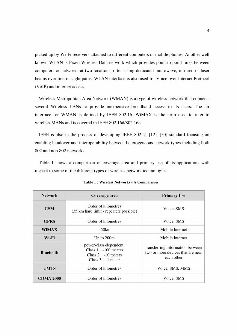
Table 1 shows a comparison of coverage area and primary use of its applications with
respect to some of the different types of wireless network technologies.
Table 1 : Wireless Networks - A Comparison
Network Coverage area Primary Use
GSM Order of kilometres
(35 km hard limit - repeaters possible) Voice, SMS
GPRS Order of kilometres Voice, SMS
WiMAX ~50km Mobile Internet
Wi-Fi Up to 200m Mobile Internet
Bluetooth
power-class-dependent:
Class 1: ~100 meters
Class 2: ~10 meters
Class 3: ~1 meter
transferring information between
two or more devices that are near
each other
UMTS Order of kilometres Voice, SMS, MMS
CDMA 2000 Order of kilometres Voice, SMS
5
1.3 Cryptography
Cryptography is about the design and analysis of mathematical techniques that enable secure
communications in the presence of malicious adversaries. It aims to send information to a proper
receiver without giving any information to a third party [137], [140]. It is a science of protecting
information by encoding it into an unreadable format. This science is of increasing importance
with the advent of broadcast and network communication, such as electronic transactions, the
internet, e-mail, and cell phones, where sensitive monetary, business, political, and personal
communications are transmitted over public channels.
Cryptography is an effective way of protecting sensitive information as it is stored on media or
transmitted through network communication paths. Although the ultimate goal of cryptography
is to hide information from unauthorized individuals, most algorithms can be broken and the
information can be revealed if the attacker has enough time, desire, and resources. So a more
realistic goal of cryptography is to make obtaining the information too work-intensive to be
worth it to the attacker. Cryptography operates by a sender scrambling or encrypting the original
message in a systematic way that obscures its meaning. The encrypted message is transmitted,
and the receiver recovers the message by unscrambling or decrypting the transmission.
Originally, the security of a cryptosystem depended on the secrecy of the entire encrypting and
decrypting procedures. Today, ciphers are used, in which the algorithm for encrypting and
decrypting could be revealed to anybody without compromising the security of a particular
message. In such ciphers a set of specific parameters, called a key, is used together with the data
as an input to the encrypting algorithm. This encrypted data together with the key serves as the
inputs to the decrypting algorithm. The encrypting and decrypting algorithms are publicly
announced and the security of the cryptogram depends entirely on the secrecy of the key. To
prevent this being discovered by accident or systematic search, the key is chosen as a very large
number.
Once the key is established, subsequent secure communication can take place by sending
cryptotext, even over a public channel that is vulnerable to total passive eavesdropping.
However, to establish the key, two users, who may not be in contact or share any secret
information initially, will have to discuss it, using some other reliable and secure channel. But
since interception is a set of measurements performed by an eavesdropper on a channel, how

6
difficult this might be from a technological point of view, any classical key distribution can in
principle be passively monitored, without the legitimate users realizing that any eavesdropping
has taken place.
Cryptographers have tried hard to solve this key distribution problem. In the 1970s a new
mathematical discovery in the form of Public Key Cryptography (PKC) [122] was introduced.
The idea of PKC is for each user to randomly choose a pair of mutually inverse transformations:
a scrambling transformation and an unscrambling transformation. Then the scrambling
transformation is published. The transformation is designed so that the unscrambling operation
cannot be deduced easily from the scrambling operation, enabling only the user to read
scrambled messages. In these systems users do not need to agree on a secret key before they send
a message. PKC was introduced in 1976 [13].
PKC systems avoid the key distribution problem by exploiting the fact that certain
mathematical operations are easier to do in one direction than the other. Their security depends
on unproven mathematical assumptions about the intrinsic difficulty of certain operations [129].
The most popular public key cryptosystem, RSA (Rivest-Shamin-Adleman) [122], gets its
security from the difficulty of factoring large numbers. This means that if ever mathematicians or
computer scientists come up with fast and clever procedures for factoring large numbers, then
the whole privacy and discretion of widespread cryptosystems could be vulnerable. Indeed,
recent work in quantum computation suggests that in principle quantum computers might
factorize huge integers in practical times, which could jeopardize the secrecy of many modern
cryptography techniques [89]. But quantum technology promises to revolutionize secure
communication at an even more fundamental level.
Cryptosystems based on elliptic curves are another exiting technology using the intractability
of certain mathematical problems. Elliptic Curve Cryptography (ECC) is an approach to public
key cryptography based on the algebraic structure of elliptic curves over finite fields, and was
first proposed in the work of Koblitz [136] and Miller [138]. The motivation for this is the fact
that there is no known sub-exponential algorithm to solve the discrete algorithm problem on a
general elliptic curve [139]. It is assumed that finding the discrete logarithm of a random elliptic
curve element with respect to a publicly-known base point is infeasible. The size of the elliptic
curve determines the difficulty of the problem. It is believed that the same level of security

7
afforded by an RSA-based system with a large modulus can be achieved with a much smaller
elliptic curve group. Use of a small group reduces storage and transmission requirements.
1.4 Secret Key and Public Key systems
Secret key (or Symmetric key) cryptography and Public key (or Asymmetric key)
cryptography are the two major cryptographic architectures.
In Secret Key both sender and receiver use the same key to encrypt and decrypt. This provides
fast computation and is also known as Symmetric cryptography. DES and AES algorithms are
based on Secret Key. However getting the secret key to the recipient in the first place is a
problem which is often handled by the Public Key system [135].
The Public Key system consists of two parts: Private Key and Public Key. The private key is
kept secret and the public key is published for everyone. The sender looks up or is sent the
recipient's public key and uses it to encrypt the message. The recipient uses the private key to
decrypt the message and never publishes or transmits the private key to anyone. Thus, the private
key is never in transit and remains invulnerable. The public key is also known as Asymmetric
cryptography. RSA and El Gamal algorithms use the public key system.
Public key cryptosystems have two primary uses, encryption and digital signatures. In this
system, each person gets a pair of keys, one called the public key and the other called the private
key. The need for the sender and receiver to share secret information is eliminated; all
communications involve only public keys, and no private key is ever transmitted or shared. In
this system, it is no longer necessary to trust the security of some means of communications. The
only requirement is that public keys be associated with their users in a trusted (authenticated)
manner (for instance, in a trusted directory). Anyone can send a confidential message by just
using public information, but the message can only be decrypted with a private key, which is in
the sole possession of the intended recipient. Furthermore, public key cryptography can be used
not only for privacy (encryption), but also for authentication (digital signatures) and other
various techniques [133].

8
In a public key cryptosystem, the private key is always linked mathematically to the public
key. Therefore, it is always possible to attack a public key system by deriving the private key
from the public key. Typically, the defence against this is to make the problem of deriving the
private key from the public key as difficult as possible. In other words, the security level is based
on the mathematical complexity.
During the encryption process, when Alice wishes to send a secret message to Bob, she looks
up Bob's public key in a directory, uses it to encrypt the message and sends it off. Bob then uses
his private key to decrypt the message and read it. No one listening in can decrypt the message
since only Bob knows his private key.
In the digital signatures, to sign a message, Alice does a computation involving both her
private key and the message itself. The output is called a digital signature and is attached to the
message. To verify the signature, Bob does a computation involving the message, the purported
signature, and Alice's public key. If the result is correct according to a simple, prescribed
mathematical relation, the signature is verified to be genuine; otherwise, the signature is
fraudulent, or the message may have been altered.
1.5 Quantum Cryptography
Based on the laws of physics, quantum cryptography allows exchange of cryptographic key
between two remote parties with unconditional security. The foundation of quantum
cryptography lies on the Heisenberg uncertainty principle, which can be interpreted as certain
pairs of physical properties are related in such a way that measuring one property prevents the
observer from simultaneously knowing the value of the other [159]. It uses quantum states of
photons to transfer cryptographic key material via polarised photons to represent bits 0 or 1.
Each photon, better known as Qubit, carries one bit of quantum information. To receive those
qubits, the recipient must determine the photon's polarisation. The act of an eavesdropper
intercepting a photon in this transmission will irretrievably change the information encoded on
that photon, thereby detecting any security breach.
The method of which a secret key is distributed using quantum cryptography is known as
Quantum Key Distribution. There has been considerable research on quantum cryptography over

9
the last few decades. In this year, a group of researchers at NIST have setup a record for high
speed QKD more than 4 million bits per second for 1km distance [15]. Very recently, a team of
researchers has taken a long step forward by demonstrating a system that is fast enough to
encrypt a video transmission [52].
Quantum cryptography has great potential to become the key technology for securing
confidentiality and privacy of communication in the future ICT world and thus to become the
driver for the success of a series of services in the field of e-government, e-commerce, e-health,
transmission of biometric data, intelligent transport systems and many others [53].
1.6 Why 802.11 Wireless Networks?
IEEE 802.11 standard is implemented by the IEEE LAN/MAN Standards Committee to carry
out wireless local area network (WLAN) communication. Its standard defines the Media Access
Control (MAC) and Physical (PHY) layers of over-the-air interface between a wireless client and
a base station or between two wireless clients.
Wi-Fi specifies standards for interoperability of wireless LANs enabling the proliferation of
multivendor 802.11 solutions. WLAN technology is experiencing tremendous growth due to the
increased bandwidth made possible by IEEE 802.11 standard. There are a number of standards
that make up 802.11 with the most popular being referred to as Wi-Fi. As Wi-Fi makes solutions
economical and widely available, the 802.11 is commercially known as Wi-Fi. Thus, Wi-Fi
networks are becoming available in homes, small offices, private corporations and many public
Hot Spots. This widespread availability is driving a de facto acceptance of Wi-Fi for WLAN.
The devices are becoming almost standard in laptops. The coverage area of Wi-Fi certified
devices is generally 100 meters. However Wi-Fi CERTIFIED n devices typically have a range of
up to 200 meters [130].
Due to its popularity and availability, the number of users too is growing rapidly. A variety of
users are seeking Wi-Fi services for wide range of activities such as business, pleasure, get in
touch, emails etc. These users include people in different professions such as business, defence,
law etc who make critical decisions and require extra level of security for their wireless
communications. Since the wired signals are open to anyone, they are more vulnerable to

10
security attacks. The existing 802.11 standard too was found to be subject to security attacks
[55], [64].
The importance of providing enhanced security to the 802.11 wireless networks has motivated
this research. As the solution, the use of quantum cryptography to enhance the security of 802.11
networks has been attempted. The proposed solution has been designed in such a way that it will
be open to numerous future expansions. Similar approaches have been attempted to distribute
secret key in wireless networks [35].
1.6.1 Security issues in WEP
The security of initial release of 802.11 is defined by Wired Equivalent Privacy (WEP). It was
intended to provide confidentiality comparable to that of a traditional wired network. WEP uses
the stream cipher RC4 for confidentiality and the CRC-32 checksum for integrity. However
WEP was identified by cryptanalysts to have severe security weaknesses [65], [68], [73]. A
wireless network is more vulnerable, because anyone can try to break into a network
broadcasting a signal. Some networks only offer WEP security systems which have been found
to be vulnerable to intrusion. Though WEP does block some intruders, the security problems
have caused some businesses to stick with wired networks until security can be improved.
WEP was found to be subject to several attacks such as Message Injection, Authentication
Spoofing, Message Decryption, IV Collisions and Message Modification [68]. AirTight
Networks has found an attack known as Caffe Latte attack on WEP [74]. During Caffe Latte
attack, it is not necessary for the attacker to be in the area of the network using this exploit. By
using a process that targets the Windows wireless stack, it is possible to obtain the WEP key
from a remote client. By sending a flood of encrypted ARP (Address Resolution Protocol)
requests, the assailant takes advantage of the shared key authentication and the message
modification flaws in 802.11 WEP. The attacker uses the ARP responses to obtain the WEP key
in less than 6 minutes.

11
1.6.2 The 802.11i Standard
To address security issues of WEP, in May 2001 IEEE set up a working task group called the
Task Group i (TGi). The task for TGi was to create a new, secure means of authentication and
privacy that would not be vulnerable to weaknesses of WEP. As a result of this, an amendment
to the IEEE 802.11 standard called IEEE 802.11i [8] was approved in 2004.
IEEE 802.11i is designed to provide enhanced security in the MAC layer for 802.11 networks.
It defines two classes of security algorithms: Robust Security Network Association (RSNA) and
Transition Security Network (TSN). IEEE 802.11i describes two new confidentiality algorithms
to address those two cipher suites, namely Temporal Key Integrity Protocol (TKIP) and Counter-
mode/CBC-MAC Protocol (CCMP) respectively [66].
TSN, also known as Pre-RSNA, provides a method to use legacy equipment that is capable of
only WEP encryption and to use RSNA capabilities in a mixed environment. In order to
accomplish the task of providing backward compatibility to accommodate WEP, TGi developed
the RSNA data confidentiality specification known as TKIP. TKIP provides significantly
improved privacy and authentication and is composed of three items: the RC4 stream cipher, the
Michael MIC function and rapid key rotation. Wi-Fi Alliance, a non-profit industry association
setup to promote the growth of WLANs, has named TKIP to be Wi-Fi Protected Access (WPA).
WPA provides more security to wireless networks than a WEP security set up. The use of
firewalls will help with security breaches which can help to fix security problems in some
wireless networks that are more vulnerable.
The CCMP data confidentiality protocol achieves confidentiality, authenticity, message
integrity and reply protection in a single transform. For confidentiality, CCMP uses the AES
block cipher in counter mode. For authentication and integrity, CCMP uses Cipher Block
Chaining Message Authentication Code (CBC-MAC) [72]. CCMP is mandatory in RSN. IEEE
802.11i separates the authentication and encryption key management. For authentication 802.11i
uses IEEE 802.1X [2] and pre-shared key. Security improvement using CCMP of IEEE 802.11i
standard is also known as Wi-Fi Protected Access 2 (WPA2). WPA2 is backward compatible
with WPA. RSNA defines a protocol using IEEE 802.1X EAPOL (Extensible Authentication
Protocol over LAN ) Key frames called 4-Way Handshake. This handshake protocol completes
the IEEE 802.1X authentication process.

12
Extensible Authentication Protocol (EAP), is an authentication framework providing for the
transport and usage of keying material and parameters generated by EAP methods. EAP is
frequently used in wireless networks and Point-to-Point connections. The encapsulation of EAP
over IEEE 802 is defined in IEEE 802.1X and known as "EAP over LANs" or EAPOL.
1.7 Research problems and proposed methodology
Wi-Fi users are growing rapidly worldwide. At the same time the number of hot spots too is
growing to serve the customer demands. It could be seen that the key used for data encryption
plays a major role to the security of the wireless communication. The amended version IEEE
802.11i of 802.11 standard has been using 4-way handshake to exchange the key between the
two parties. The main key obtained through 4-way handshake is the Pairwise Transient Key
(PTK). This PTK is used to build the key hierarchy containing few other keys that are needed for
various encryption functionalities. Thus it is essential to have the PTK distributed safely. In
addition, IEEE 802.11 standard requires the encryption keys to be refreshed regularly for safety
reasons [8], [55], [45]. The AP can refresh the PTK either periodically or upon the request from
the STA by running another 4-Way Handshake with the same Pairwise Master Key (PMK).
Further, it was shown that 4-way handshake is subject to security issues [57], [58].
Since Wi-Fi networks are widely available, it is necessary to provide enough security to users
who use this service to communicate extremely sensitive information. Hence the main aim of
this research work is to improve the security aspect of Wi-Fi networks. It is required to find a
proper way to modify the existing IEEE 802.11 protocol with minimal impacts. Also the
proposed solution is designed to have flexibility for further enhancements.
To improve the security of IEEE 802.11i, quantum cryptography has been used in this
proposed solution. Instead of using 4-way handshake, quantum key distribution has been used to
distribute the secret key. Since the key obtained via QKD provides unconditional security,
802.11 key hierarchy too will inherit the same level of protection.
The proposed modification comprises of two stages: firstly to transmit the photons, secondly to
extract the secure key through the four main phases. Thus the proposed QKD based protocol can

13
be split into quantum channel to transmit the photons and 4-phase handshake to recover the final
key.
The proposed QKD based Wi-Fi protocol starts soon after the Extensible Authentication
Protocol (EAP) is completed. At this moment, the photon transmission takes place via quantum
channel. Once the quantum transmission finishes, the 4-phase handshake begins via the 802.11
wireless channel. At the end of 4-phase handshake both AP and STA holds unconditionally
secured key which is used to derive the existing IEEE 802.11 key structure. From this point
onwards the standard 802.11 protocol proceeds.
To implement the 4-phase handshake, existing EAPOL has been used. In fact, EAPOL has
been used to implement the 4-way handshake protocol. In the proposed 4-phase handshake, some
of the identified EAPOL packet fields have been modified to carry relevant information.
In essence, this research uses quantum cryptography to obtain the key hierarchy of RSNA
IEEE 802.11 to offer secured communication for its users. The key hierarchy obtained via QKD
is more secure than that of 4-way handshake, raising the overall security of the communication to
the highest level.
1.8 Experimental Procedure
The experimental process can be broken down into two main stages. Firstly the quantum
channel used for photon transmission, secondly the wireless channel where the secret key is
recovered. This research is mainly aiming at the wireless communication process on how to
implement the proposed QKD based Wi-Fi protocol in the existing 802.11i protocol.
The proposed modifications have been focused onto a specific portion of the existing IEEE
802.11i and EAPOL protocols. To be precise, the management frames that are being used during
association and the communication flows that execute 4-way handshake. Thus, for experimental
implementation it is not necessary to write the whole 802.11i protocol just to analyse only the
key distribution part. Hence the experimental analysis has been done by simulation using
Simulink.
Focusing on the proposed modifications, the communication flows impacted by the key
distribution have been written in C++. The implementation includes the execution of 4-phase

14
handshake, consisting of 4 main stages. Thus each of the stages comprises several
communication flows. A new method of implementing the third stage of 4-phase handshake,
known as reconciliation, has also been done in the development. The C++ code has been
modelled into S-Functions of Simulink to set up the testing model.
The main parameters that control the proposed QKD based Wi-Fi protocol have been
identified. Those parameters have been thoroughly used for simulations to see the behaviour on
various scenarios.
There are no Wi-Fi enabled devices with embedded transmitters and receivers for quantum
transmission as of today. Thus the experimental set up that has been used for parallel QKD
project, which involve the hardware implementation, has been used for the quantum
transmission. More details about this project are described in sections 4.1 and 5.2. The output
key bit streams and the bases have been used as the input to this research. Since a wireless
channel is totally independent of the quantum channel, this approach does not cause any impact
on the results of the simulations.
Overall, the simulation set up and input test data have been used as realistically as possible to
make the results more accurate.
1.9 Specific Contributions of the research
Out of many different wireless network categories, IEEE 802.11 WLANs have become very
popular. The number of Wi-Fi hot spots around the world is growing rapidly to serve demanding
customer needs. The majority of those hot spots located on public locations such as airports,
coffee shops etc cause real concerns with the security aspects of overall communication.
Wireless networks are vulnerable to security attacks because the broadcast takes place in open
air. It was found that even the 4-way handshake of security enhanced IEEE 802.11i protocol is
subject to security issues [55], [57], [58].
The aim of the proposed solution is to provide enhanced security to the existing IEEE 802.11
wireless networks. In doing so, a novel protocol has been developed to distribute secret key
needed to encrypt data. This new protocol is based on quantum cryptography which uses QKD to

15
distribute the secret key. The most important contribution of this approach is the unconditional
security offered to the wireless communication. A strong encryption key provides the clients
joining to a Wi-Fi network much needed security throughout the communication session.
Required modifications to the existing IEEE 802.11i protocol have been done with much care
such that it will not have any impact on the existing frame format. Only some of the identified
fields have been modified to implement the new protocol changes. Most importantly, if any of
the participants is not equipped with quantum devices or does not want the security offered by
QKD, they can still move on with the existing Wi-Fi communication.
Further, this approach is open to vast amounts of future expansions. Possible extensions of the
proposed QKD based Wi-Fi protocol for other types of wireless networks are also discussed.
In essence, this research provides a novel way of distributing the encryption key in Wi-Fi
networks by using QKD. This approach raises the security of the overall communication to a
new height with the unconditional key security offered by quantum cryptography.
1.10 Structure of the thesis
This thesis comprises seven chapters. This chapter mainly focused on the introductions to the
main areas of the research work. The aim was to give a brief introduction of the direction in
which this research work is focused on.
Chapter 2 extends the discussion further into a literature overview of wireless networks and
security issues. It discusses IEEE 802.11 wireless family, with special focus on IEEE 802.11i,
IEEE 802.1X and also on wireless security with types of attacks against wireless networks.
Quantum Cryptography is also discussed with special focus on QKD which has been used to
implement the proposed QKD based Wi-Fi protocol.
Chapter 3 describes the methodology used. Detailed description of the proposed protocol for
IEEE 802.11 key exchange has been given. The proposed modifications to the existing 802.11
standards are also discussed in depth.

16
Chapter 4 is dedicated to implementation of the new protocol. Methods used for
implementation and simulation have been discussed in detail. It also gives implementational
details of the quantum channel as well.
Chapter 5 evaluates the results of the research work. Performance and assessments conducted
under various scenarios are discussed in this chapter. Analyses of the proposed work with the
results obtained are discussed. It also gives comparisons and discusses the usefulness of the
protocol.
Chapter 6 has been dedicated to discuss how the same proposed protocol can be implemented
as a Multi Agent System. This work has been done as a future enhancement to this research.
Significant amount of work has been done in this direction.
Conclusion and future work are discussed in Chapter 7. This chapter covers discussion on the
overall solution. Summary of the methodologies used, results etc are also discussed. It is shown
that there are numerous extensions to this research possible.
Finally, the bibliography and appendices that have been used for this research work are listed.
The appendices include research papers published, patents, unpublished research papers and
Universal hash functions.

17
Chapter 2 Research Content: A Survey
This chapter surveys literature that is relevant to the scope of this research. The main focus is
on the IEEE 802.11 and IEEE 802.1X frames that have been used in the proposed QKD based
Wi-Fi protocol. The EAPOL frame and field structures are also discussed as some of the selected
EAPOL fields have been modified to transport QKD specific information.
This chapter also discusses the quantum cryptography and most importantly the proposed
QKD based Wi-Fi protocol. Overall operation of the main four phases, that have been used to
recover the final key, has also been described. The aim of this chapter is to give some theoretical
insight into the sections that are required to implement proposed QKD based Wi-Fi protocol.
2.1 802.11 Network Architecture
The IEEE 802.11 architecture consists of several components that interact to provide a WLAN
that supports client mobility transparently to upper layers.
Station: Station (STA) is the component that connects to the wireless medium.
Basic service set (BSS): BSS is the basic building block of an IEEE 802.11 LAN. The BSS
refers to the collection of networking stations which communicate with one another to enable
communication within a WLAN. Each BSS is identified by an SSID (Service Set Identifier)
which is a code attached to all packets on a wireless network to identify each packet as part of
that network. Besides identifying each packet, an SSID also facilitates to uniquely identify a
group of wireless network devices used in a given "Service Set".
There are two types of BSS namely IBSS (Independent Basic Service Set) and Infrastructure
Network.
Independent Basic Service Set: The IBSS are the ad-hoc wireless networks that generally
consist of client machines without an Access Point. The IBSS is the most basic type of IEEE
802.11 LAN. A minimum IEEE 802.11 LAN may consist of only two STAs.

18
Infrastructure Network: Infrastructure Network Service set comprises of both the networking
stations and the Access Point.
Distribution System (DS): Distribution System is the mechanism by which one AP
communicates with another to exchange frames for stations in their BSSs, forward frames to
follow mobile stations from one BSS to another and exchange frames with wired network.
Extended Service Set (ESS): The DS and BSSs allow IEEE standard 802.11 to create a wireless
network of arbitrary size and complexity. IEEE Std 802.11 refers to this type of network as the
ESS network. An ESS is the union of the BSSs connected by a DS. The ESS does not include the
DS. Figure 1 shows the ESS architecture [1].
Figure 1 : ESS Architecture [1]
Robust Security Network Association (RSNA): In a RSNA, IEEE standard 802.11 provides
functions to protect data frames, IEEE standard 802.1X-2004 provides authentication and a
Controlled Port, and IEEE Std 802.11 and IEEE Std 802.1X-2004 collaborate to provide key
management. All STAs in an RSNA have a corresponding IEEE 802.1X entity that handles these
services. This standard defines how an RSNA utilizes IEEE standard 802.1X-2004 to access
these services. An RSNA utilizes non-IEEE-802 protocols for its Authentication and Key
Management (AKM) services.

19
An RSNA defines a number of security features in addition to WEP and IEEE 802.11
authentication. These features include the following:
• Enhanced authentication mechanisms for STAs
• Key management algorithms
• Cryptographic key establishment
• An enhanced data cryptographic encapsulation mechanism, called Counter mode with
Cipher-block chaining Message authentication code Protocol (CCMP), and, optionally,
Temporal Key Integrity Protocol (TKIP)
STA Authentication and Association
A STA keeps two state variables for each STA with which direct communication via wireless
medium is needed.
Authentication state: The values are unauthenticated and authenticated
Association state: The values are unassociated and associated.
These two variables create three local states for each remote STA:
State 1: Initial start state, unauthenticated, unassociated
State 2: Authenticated, not associated
State 3: Authenticated, Associated. The state of the sending STA given by Figure 2 is with
respect to the intended receiving STA [8].

20
Figure 2 : Relationship between state variables and services [1]
In state 1, the station may use a very limited number of frame types. These frames are to find
an IEEE 802.11 WLAN, an ESS, and its APs, to complete the required frame handshake
protocols, and to implement the authentication service. If a station is part of an IBSS, it is
allowed to implement the data service in state 1. In state 2, additional frame types are allowed to
provide the capability for a station in state 2 to implement the association, reassociation, and
disassociation services. In state 3, all frame types are allowed and the station may use the data
delivery service. A station must react to frames it receives in each of the states, even those that
are disallowed for a particular state. A station will send a deauthentication notification to any
station with which it is not authenticated if it receives frames that are not allowed in state 1. A
station will send a disassociation notification to any station with which it is authenticated, but not
associated, if it receives frames not allowed in state 2. These notifications will force the station
that sent the disallowed frames to make a transition to the proper state in the state diagram and
allow it to proceed properly toward state 3.

21
2.2 Security in 802.11 Networks
As wireless communications use the airwaves, they are intrinsically more vulnerable to
interceptions and attacks than their wired counterparts. With the service becoming more popular,
the risks to users of wireless technology have increased significantly. Thus, there are a great
number of security risks associated with the current wireless protocols and encryption methods
[64], [109]. Some of the common types of attacks against wireless networks are; Denial of
Service (DoS) attacks, Identity theft (MAC spoofing), ARP poisoning, Network injection,
Session High jacking, Caffe Latte attack etc.
DoS attacks are typically associated with 802.11 wireless communications [109], [110].
During DoS attacks, users are preventing from accessing network resources by flooding a
network with degenerate or faulty packets, crowding out legitimate traffic and causing systems
(Access Points) not to respond. Wireless systems are particularly susceptible to DoS attacks
because of the way different layers of the OSI stack interact with one another.
MAC spoofing refers to altering the MAC address on an NIC (Network Interface Controller)
card. MAC address spoofing in this context relates to an attacker altering the manufacturer-
assigned MAC address to a value that facilitates invading a LAN. Most wireless systems allow
some kind of MAC filtering to only allow authorized computers with specific MAC IDs to gain
access and utilize the network. ARP operates by broadcasting a message across a network, to
determine the Layer 2 address (MAC address) of a host with a predefined Layer 3 address (IP
address) [111]. The host at the destination IP address sends a reply packet containing its MAC
address. Once the initial ARP transaction is complete, the originating device then caches the
ARP response, which is used within the Layer 2 header of packets that are sent to a specified IP
address. An ARP Spoofing attack is the egression of unsolicited ARP messages. These ARP
messages contain the IP address of a network resource, such as the default gateway, or a DNS
server, and replaces the MAC address for the corresponding network resource with its own MAC
address. Network devices, by design, overwrite any existing ARP information in conjunction
with the IP address, with the new, counterfeit ARP information. The attacker then takes the role
of man in the middle; any traffic destined for the legitimate resource is sent through the attacking

22
system. As this attack occurs on the lower levels of the OSI model, the end-user is oblivious to
the attack occurrence.
In addition, there are tools that are able to crack security information of Wi-Fi connections
[141], [114].
2.3 IEEE 802.11i Standard
The IEEE 802.11 standard defines three main type of frames used for communicating
managing and controlling the wireless link:
• Management Frames
• Control Frames
• Data Frames
Management frames enable stations to establish and maintain communications. Types of
management frames are: Beacon frame, Probe request frame, Probe response frame, Association
request frame, Association response frame, Reassociation request frame, Reassociation response
frame, Disassociation frame, Authentication frame, Deauthentication frame.
Control frames ensure the delivery of data frames between two parties. Types of control
frames are: Request to Send (RTS) frame, Clear to Send (CTS) frame, Acknowledgement (ACK)
frame.
Data frames provide transportation of data. 802.11 defines a data frame type that carries
packets from higher layers, such as web pages, printer control data, etc., within the body of the
frame. In fact the main purpose of having a WLAN is to transport data.
2.3.1 Management Frames impacted by proposed modifications
The main aim of this section is to highlight the IEEE 802.11 frames and their fields that have
been impacted by the proposed QKD based Wi-Fi protocol. Only the relevant frames and fields
are discussed here. These changes help STA and AP to decide how to proceed with the proposed
QKD based Wi-Fi protocol. Proposed modifications to fields of some of the selected frames have
been discussed in Chapter 3.

23
2.3.1.1 Beacon Frame
In infrastructure BSS, APs periodically transmit beacons to announce the presence of a
WLAN. Beacon frame, one of the management frames in IEEE 802.11 based WLANs, carries all
the information about the network.
In IBSS network, beacon generation is distributed among the stations. While in ad-hoc
networks, since there are no APs, one of the peer stations assumes the responsibility for sending
the beacon.
A STA seeking to join a WLAN has two choices: Passive scan or Active scan.
In passive scan, STA wait on each channel to hear a Beacon from an AP.
In active scan, STA transmits Probe Request on all available channels until the STA finds an
AP. STA sends Probe Request and waits long enough to hear a Probe Response. Upon receiving
the Probe Request from STA, AP transmits Probe Response frame.
The frame format of beacon is shown in Table 2. Some of the information fields that beacon uses
are:
Beacon interval: This represents the amount of time between beacon transmissions. Before a
station enters power save mode, the station needs the beacon interval to know when to wake up
to receive the beacon (and learn whether there are buffered frames at the access point).
Timestamp: Once a beacon frame is received, a station uses the timestamp value to update its
local clock. This process enables synchronization among all stations that are associated with the
same access point.
Service Set Identifier (SSID): The SSID identifies a specific wireless LAN. Before
associating with a particular wireless LAN, a station must have the same SSID as the access
point. By default, access points include the SSID in the beacon frame to enable sniffing functions
to identify the SSID and automatically configure the wireless network interface card (NIC) with
the proper SSID. Some access point vendors have an option to disable the SSID from being
broadcast in beacon frames to reduce security issues.

24
Table 2 : Beacon Frame Body [56]
Order Information
1 Time Stamp
2 Beacon Interval
3 Capability
4 SSID
5 Supported Rates
6 Frequency Hopping Parameter Set
7 DS Parameter Set
8 CF Parameter Set
9 IBSS Parameter Set
10 Traffic Indication Map (TIM)
11 Country
12 FH Parameters
13 FH Pattern Table
14 Power Constraint
15 Channel Switch Announcement
16 Quiet
17 IBSS DFS
18 TPC Report
19 ERP Information
20 Extended Supported Rates
21 RSN
22 BSS Load
23 EDCA Parameter Set
24 QoS Capability
Last Vendor Specific
Capability Information: This signifies requirements of stations that wish to belong to the
wireless LAN that the beacon represents. For example, this information may indicate that all
stations must use wired equivalent privacy (WEP) in order to participate on the network.
This two octet Capability Information field contains a number of subfields that are used to
indicate requested or advertised optional capabilities. Figure 3 shows the format of the Capability
Information field.

25
Figure 3 : Capability information field [8]
2.3.1.2 Probe Request Frame
Probe Request is a subtype of management frame. Table 3 shows the frame body of Probe
Request. If the dot11MultiDomainCapabilityEnabled attribute is true, a STA may include a
Request information element in the Probe Request frame. The
dot11MultiDomainCapabilityEnabled indicates the true or false state of other particular attributes
of 802.11 frames, depending on the state and condition of the communication. The Extended
Supported Rates element is present whenever there are more than eight supported rates, and it is
optional otherwise. One or more Vendor Specific information elements may appear in this frame.
This information element follows all other information elements.
Table 3 : Probe Request Frame Body [56]
Order Information
1 SSID
2 Supported Rates
3 Request Information
4 Extended Supported Rates
Last Vendor Specific
2.3.1.3 Probe Response Frame
The frame body of a management frame of subtype Probe Response contains the information
shown in Table 4 [8]. If the dot11MultiDomainCapabilityEnabled attribute is set to true, the
Probe Response frame contains a Country information element and all information elements
identified by the Requested Element IDs of a Request information element.
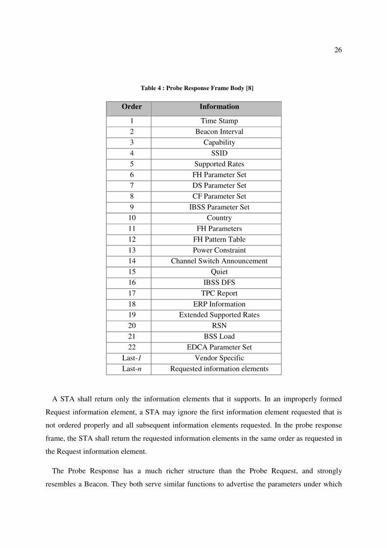
26
Table 4 : Probe Response Frame Body [8]
Order Information
1 Time Stamp
2 Beacon Interval
3 Capability
4 SSID
5 Supported Rates
6 FH Parameter Set
7 DS Parameter Set
8 CF Parameter Set
9 IBSS Parameter Set
10 Country
11 FH Parameters
12 FH Pattern Table
13 Power Constraint
14 Channel Switch Announcement
15 Quiet
16 IBSS DFS
17 TPC Report
18 ERP Information
19 Extended Supported Rates
20 RSN
21 BSS Load
22 EDCA Parameter Set
Last-1 Vendor Specific
Last-n Requested information elements
A STA shall return only the information elements that it supports. In an improperly formed
Request information element, a STA may ignore the first information element requested that is
not ordered properly and all subsequent information elements requested. In the probe response
frame, the STA shall return the requested information elements in the same order as requested in
the Request information element.
The Probe Response has a much richer structure than the Probe Request, and strongly
resembles a Beacon. They both serve similar functions to advertise the parameters under which

27
the WLAN operates, and are frequently referred to as a pair ("Beacon and Probe Response" or
"Beacon or Probe Response").
Both Probe Request and Probe Response frames contains Request Information field. STA may
include Request Information Elements in Probe Request frame if the
dot11MultiDomainCapabilityEnabled attribute is true.
2.3.1.4 Information Element
The Information Elements (IE) are blobs of data of varying sizes. Each data blob is tagged
with a type number and a size, and it is understood that an IE of a certain type has its data field
interpreted in a certain way.
New IEs can be defined by newer versions of 802.11 specification [45]. IE is a part of
management frames in the IEEE 802.11 wireless LAN protocol. Usually there are several IEs
inside each such frame. The format of Request Information element is shown in Figure 4.
Figure 4 : Request Information element [1]
The Information elements are a device's way to transfer descriptive information about itself
inside management frames. There are usually several IEs inside each such frame. The common
structure of an IE is shown in Figure 5.

28
Figure 5 : Information Element Format [1]
The requested Elements IDs are the list of elements that are to be included in the responding
STA’s Probe Response frame. The requested Element IDs shall be listed in order of increasing
element ID. The set of valid Element IDs in IEEE 802.11 standard is shown in Table 5. The STA
shall return only those information elements that it supports. In the Probe Response frame, the
STA shall return the requested IEs in the same order requested in the Request information
element of the Probe Request frame [56]. It could be seen that there are a number of IEs that are
not used in the present IEEE 802.11 standard.
In addition to Probe Request and Probe Response frames, both Capability and IE fields are
present in Association Request, Association Response, Reassociation Request and Reassociation
Response frames as shown below. In all these frames Vendor Specific field may contains one or
more vendor-specific IEs.

29
Table 5 : Element IDs [56]

30
2.3.1.5 Association Request Frame
Once STA identifies a compatible network and gets authenticated, it may attempt to join the
network by sending an Association Request frame [45]. The Capability Information field is used
to indicate the type of network the STA wants to join. Before an AP accepts an association
request, it verifies that the Capability Information, SSID and Supported rates all match the
parameters of the network. Table 6 shows the frame structure of the association request frame.
Table 6 : Association Request Frame Body [56]
Order Information
1 Capability
2 Listen Interval
3 SSID
4 Supported Rates
5 Extended Supported Rates
6 Power Capability
7 Supported Channels
8 RSN
9 QoS Capability
Last Vendor Specific
2.3.1.6 Association Response Frame
An AP sends Association Response frame to requesting STA (that initiated the Association
Request frame) indicating whether or not it is accepting the association. Table 7 shows the
association response frame body.
Table 7 : Association Response Frame Body [8]
Order Information
1 Capability
2 Status Code
3 AID
4 Supported Rates
5 Extended Supported Rates
6 EDCA Parameter Set
Last Vendor Specific

31
2.3.1.7 Reassociating Request Frame
STAs moving between basic areas within the same ESS need to reassociate with the network
before using resources of the new AP. Since the STA is already associated with an AP in the
ESS, it sends Reassociation Request frame to the ESS through new AP. The STA will need to
reassociate with the new AP so that it will need to negotiate the forwarding of data frames from
the old access point and update its association table. The reassociation request frame body is
shown in Table 8.
Table 8 : Reassociation Request Frame Body [8]
Order Information
1 Capability
2 Listen Interval
3 Current AP Address
4 SSID
5 Supported Rates
6 Extended Supported Rates
7 Power Capability
8 Supported Channels
9 RSN
10 QoS Capability
Last Vendor Specific
2.3.1.8 Reassociation Response Frame
When an AP receives a Reassociation Request frame, it sends a Reassociation Response frame
to requesting STA indicating whether or not it is accepting the reassociation. If the reassociation
is successful, the new access point will indicate this status in the status code element. Table 9
shows the reassociation response frame structure.

32
Table 9 : Reassociation Response Frame Body [8]
Order Information
1 Capability
2 Status Code
3 AID
4 Supported Rates
5 Extended Supported Rates
6 EDCA Parameter Set
Last Vendor Specific
2.3.2 RSNA Key Hierarchy
RSNA defines two types of key hierarchies to divide initial key material into useful keys. The
two key hierarchies are: Pairwise key hierarchy, which is used to protect unicast traffic and,
Group key hierarchy which is used to protect multicast and broadcast traffic.
CCMP take a single master key and expand it into the different keys required for frame
protection operations. By using key derivation, stations can refresh encryption keys without re-
running the whole authentication process [45]. The master key is the root secret that must be
carefully protected because all keying material is derived from it. Part of the key hierarchy’s
purpose is to derive keys used to protect transmission of the temporal keys. Figure 6 shows the
Pairwise key hierarchy [30], [8].
In the pairwise key hierarchy, the PMK is 256 bits long. In WPA-PSK, the pairwise master key
is generated using the configurations defined in an authentication server (eg: RADIUS) and sent
to AP. To obtain the temporal keys, the PMK is expanded through the use of a defined
pseudorandom function (PRF). To further randomize data, this expansion is based on the pre-
master key, the MAC address of both AP and STA, and two random nonce values transmitted as
part of the 4-way protocol. The result of PRF on PMK is the 384 bit long PTK. The nonce is a
function of the security control field, the frame counter, and the address of the sender. Since only
the frame counter is variable, nonce is derived directly from the counter. The ANonce is a
random or pseudo-random value generated by the AP, while the SNonce is a random or pseudo-
random value generated by the STA.

33
Figure 6 : Pairwise Key Hierarchy of IEEE 802.11i of CCMP [30]
The extraction of PTK can be summarized as below:
PTK � PRF(PMK, ANonce, SNonce, A-MAC, S-MAC)
Where;
ANonce : A nonce from the AP
SNonce : A nonce from the STA
A-MAC : AP's MAC address
S-MAC : STA's MAC address
The PTK then gets divided into three keys. The first key is the EAPOL-Key Confirmation Key
(KCK). The KCK is used by the EAPOL-key exchanges to provided data origin authenticity.
KCK is also used to calculate Message Integrity Code (MIC). The second key is the EAPOL-
Key Encryption Key (KEK). The KEK is used by the EAPOL-key exchanges to provide for
confidentiality. KEK is used to encrypt the Group Temporal Key (GTK). The third key is the
Temporal Key (TK), which is used by the data-confidentiality protocols to encrypt unicast data
traffic.

34
2.3.3 4-Way Hand Shake Protocol
RSNA defines a protocol using IEEE 802.1X EAPOL-Key frames called 4-Way Handshake.
This handshake performs the IEEE 802.1X authentication process. It allows the STA and the AP
to generate key hierarchy to provide encryption of traffic. Figure 7 shows the 4-way handshake
process [5].
Figure 7 : 4-Way Handshake [5]

35
2.3.4 Security Issues in 4-Way Hand Shake Protocol
Recent research work explores some of the flaws of 4-way handshake [115], [58], [55], [57],
[64]. It was shown that flow (1) of 4-way handshake is vulnerable to security attacks. When the
STA does not receive flow (1) within the expected time interval after a successful 802.1X
authentication, it will disassociate, de-authenticate and try the same or another AP again [58].
Even though the STA does not use any other timeout during the 4-Way Handshake, the AP will
timeout and retry the message. Furthermore, the AP will de-authenticate the STA if it does not
receive a valid response after several retries. This means the AP can initialize only one
handshake instance and accept only the expected response, the STA must accept all messages in
order to allow the handshake to proceed. Hence, an attacker can easily interfere with the
handshake protocol by inserting a forged flow (1). This leads to more severe vulnerabilities than
might be expected.
Further, it was shown that the flow (1) of 4-way handshake is subject to DoS attacks. This
attack is possible since the flow (1) of 4-way handshake does not have any integrity check
implemented. Whereas the other flows of 4-way handshake offers integrity check via MIC. Thus
it is possible for intruders to flood flow (1) to the STA after the 4-way handshake has completed
generating heavy traffic eventually causing the system to fail.
In addition, the tool Aircrack-ng [114] is an 802.11 WEP and WPA-PSK keys cracking
program that can recover keys once enough data packets have been captured.
2.4 802.1X Port Based Network Access Control
IEEE 802.1X [10] is an IEEE standard for port-based Network Access Control ratified as a
standard in 2004. IEEE 802.1X offers an effective framework for authenticating and controlling
user traffic to a protected network, as well as dynamically varying encryption keys. It supports
multiple authentication methods, such as token cards, Kerberos, one-time passwords, certificates,
and public key authentication. 802.1X is more commonly used in wireless networks because of
mobile technology’s vulnerability to over the air signal reception. In addition, networks use
802.1X because it offers a convenient way to deliver cryptographic keys for wireless LANs,
which typically provide security via encryption. The EAPOL protocol was also modified for use

36
with IEEE 802.1AE (MACSec) [161] and IEEE 802.1AR (Secure Device Identity, DevID) [160]
in 802.1X-2010 [21] to support service identification and optional point to point encryption over
the local LAN segment.
The 802.1X architecture consist of three key components:
1. Supplicant: The user, Station (STA) or client that wants to be authenticated
2. Authenticator: The Authenticator or the Access Point (AP) allows only the
supplicants who are authorized by the authentication server to gain access to the
network.
3. Authentication Server: The actual server doing the authentication is called
Authentication Server (AS). Widely used Authentication Servers are RADIUS,
DIAMETER. AS is located at the wired side of the AP.
2.4.1 IEEE 802.1X Authentication
The key protocol in 802.1X is called EAP over LANs (EAPOL). It is currently defined for
Ethernet-like LANs including 802.11 wireless, as well as token ring LANs (including FDDI).
The authentication process in 802.1X is shown in Figure 8. It is assumed that AS is running on
RADIUS. The main flows of IEEE 802.1X authentication process are as follow (Figure 8):
• Flow (2) EAP Request/Identity: The AP sends an EAP-Request/Identity packet to the
STA as soon as it detects that the link is active. That is the STA is associated with the
AP.
• Flows (3A) EAP Response/Identity, (3B) RADIUS Access Request: The STA sends an
EAP-Response/Identity packet to the AP, which is then passed on to the AS.
• Flows (4A) RADIUS Access Challenge, (4B) EAP Request: The AS sends back a
challenge to the AP. The AP unpacks this information and repackages it into EAPOL
and sends it to the STA.

37
• Flows (5A) EAP Response, (5B) RADIUS Access Request: The STA responds to the
challenge via the AP and passes the response onto the AS. The AS uses a specific
authentication algorithm to verify the client's identity. This could be through the use of
digital certificates or other EAP authentication type.
• Flows (6A) RADIUS Access Accept, (6B) EAP Success: If the STA provides proper
identity, the AS responds with a success message, which is then passed onto the STA.
• Flow (7) Data Exchange: The AP now opens port for the STA to access to the LAN
based on attributes that came back from the AS.
Figure 8 : IEEE 802.1X Authentication [34]

38
The 802.1X EAPOL-Key packets are used to distribute per-session keys to those stations
successfully authenticated. The access point uses the session keys to build, sign and encrypt an
EAP key message that is sent to the client immediately after sending the success message. The
802.1X (EAPOL) protocol provides effective authentication for its users. If configured to
implement dynamic key exchange, the 802.1X authentication server can return session keys to
the AP along with the accept message. The AP uses the session keys to build, sign and encrypt
an EAP key message that is sent to the STA immediately after sending the success message. The
STA can then use contents of the key message to define applicable encryption keys [34].
2.4.2 EAPOL-Key frames
IEEE 802.11 standard uses EAPOL-Key frames to exchange information between STAs and
APs. These exchanges result in cryptographic keys and synchronization of security association
state. EAPOL-Key frames are used to implement three different exchanges:
1) 4-way handshake, to confirm that the PMK between associated STAs is the same and live
to transfer the GTK to the STA.
2) Group Key Handshake, to update the GTK at the STA
3) PeerKey initial SMK Handshake to deliver the SMK and final 4-way STK Handshake to
deliver the STK to the initiating and peer STAs.
Figure 9 depicts the format of an EAPOL-Key frame.

39
Figure 9 : EAPOL-Key Frame [8]
A few of the important fields of EAPOL-Key frame that focused on this research are discussed
below.
a) Description Type: This one octet field has a value defined by IEEE 802.1X-2004
standard, identifying the IEEE 802.11 key descriptor.
b) Key Information: This 2 octet field specifies characteristics of the key. The key
information bit layout is shown in Figure 10.
Figure 10 : Key Information bit layout [8]
1) Key Type (bit 3): This bit specifies whether this EAPOL-Key frame is a part of a 4-
way Handshake deriving a PTK.

40
2) Install (bit 6): This bit is to be used in association with Key Type (bit 3) field.
If Key Type = 1, then for:
� Install bit = 1 means IEEE 802.1X component shall configure the temporal
key derived from this message into its IEEE 802.11 STA.
� Install bit = 0 means IEEE 802.1X component shall not configure the
temporal key derived from this message into its IEEE 802.11 STA.
3) Key Ack (bit 7): This bit is set in messages from the AP if an EAPOL-Key frame is
required in response to this message and is clear otherwise.
c) Key Nonce: This is a 32-octet field. It conveys the ANonce from the AP and the SNonce
from the STA. It may contain 0 if a nonce is not required to be sent.
d) Key Data: This field is a variable-length field that is used to include any additional data
required for the key exchange that is not included in the fields of the EAPOL-Key frame.
The additional data may be zero or more information element(s). Information elements
sent in the Key Data field include the Element ID and Length subfields.
2.5 Use of EAP methods for Mutual Authentication
802.1X ties a protocol called EAP (Extensible Authentication Protocol) to both the wired and
wireless LAN media. EAP is defined in RFC 3748 [62] and was updated by RFC 5247 [75].
EAP is an authentication framework frequently used in wireless networks and Point-to-Point
connections while 802.1X (EAPOL) is a delivery mechanism that doesn't provide the actual
authentication mechanisms. When utilizing 802.1X, users need to choose an EAP type which
defines how the authentication takes place. Some of the commonly used EAP variations in
wireless networks are EAP-TLS (EAP Transport Layer Security), EAP-AKA (EAP for UMTS
Authentication and Key Agreement), PEAP, LEAP (Lightweight Extensible Authentication
Protocol), EAP-SIM (EAP for GSM Subscriber Identity) and EAP-TTLS (EAP-Tunnelled

41
Transport Layer Security). In addition, a number of vendor specific methods and new proposals
also exist.
The specific EAP type resides on the authentication server and within the operating system or
application software on the client devices. The access point acts as a "pass through" for 802.1X
messages, which means that users can specify any EAP type without needing to upgrade an
802.1X-compliant access point. EAP only defines message formats. Each of those protocols that
use EAP defines a way to encapsulate EAP messages within that protocol's messages.
EAP-Transport Layer Security (EAP-TLS) is defined in RFC 5216 [102]. It supports for
certificate-based mutual authentication and key derivation, utilizing the protected cipher suite
negotiation, mutual authentication and key management capabilities of the TLS protocol. The
security of the TLS protocol is strong and still considered one of the most secure EAP standards
available and is universally supported by all manufacturers of wireless LAN hardware and
software.
EAP-Tunnelled Transport Layer Security (EAP-TTLS) [113] is an EAP protocol that extends
TLS. It was co-developed by Funk Software and Certicom. It is widely supported across
platforms offering good security. The client can but does not have to be authenticated via a CA-
signed (Certificate Authority) PKI (Public Key Infrastructure) certificate to the server. This
greatly simplifies the setup procedure as a certificate does not need to be installed on every client
[112].
After the server is securely authenticated to the client via its CA certificate and optionally the
client to the server, the server can then use the established secure connection (as a tunnel) to
authenticate the client. It can use an existing and widely deployed authentication protocol and
infrastructure, incorporating legacy password mechanisms and authentication databases, while
the secure tunnel provides protection from eavesdropping and man-in-the-middle attack. Note
that the user's name is never transmitted in unencrypted clear text, thus improving privacy.

42
2.6 One-Time Pad
In 1917, Gilbert Vernam, an employee of AT&T, built a machine to generate pseudorandom
strings of characters for use as encryption keys in a cipher called a one-time pad (also referred to
as the Vernam cipher). Before the advent of quantum cryptography the one-time pad was widely
regarded as the only cryptosystem which guaranteed absolute security – often termed the ‘holy
grail’ of cryptography. The one-time pad uses a random key of the same length as the plaintext,
if the message is intercepted the cryptanalyst has absolutely nothing to give them a foothold [69].
The pseudo-random encryption key means that there is no point looking for repeating patterns,
so essentially the only information an attacker has is that if the ciphertext is n letters long, the
plaintext must be one of all the possible messages of length n. One-time pads are currently only
used when security is of the utmost importance due to the problem of key distribution. For a one-
time pad cryptosystem to work effectively both the receiver and the sender need identical sets of
strings of random characters to use as encryption keys. New keys must be physically exchanged
on a regular basis to avoid key reuse, a very time consuming operation if the correspondents are
geographically distant. This highlights the importance of “key distribution” process with high
security. If the key distribution can be achieved at the highest level of security, the data
communication will invariably safe.
2.7 Use of Virtual Private Network in Wi-Fi Networks
Virtual Private Network (VPN) tunnels have been used to provide confidentiality and integrity
for data over untrusted networks such as the internet. VPN gateway is responsible for
authenticating users and controlling which destinations can be reached.
VPNs are being leveraged for endpoint security enforcement, either alone or in conjunction
with a broader network access control deployment [70]. Endpoint devices are checked for
compliance before being granted network access.
There are several VPN tunnelling standards including Point-to-Point Tunnelling Protocol
(PPTP), Layer 2 Tunnelling Protocol (L2TP), Internet Protocol Security (IPsec) and the Secure
Sockets Layer protocol (SSL). In IPsec and PPTP VPN technologies, the encryption usually
happens at the network layer of OSI protocol stack. Recent VPN implementations use SSL
tunnelling for ease of firewall, NAT (Network Address Translation) and proxy traversal where

43
the encryption happens at the presentation layer (layer 6 of OSI model). Most VPN solutions
emulate a layer 2 connection by encapsulating layer 2 within layer 3 IPsec or layer 6 SSL. Layer
2 emulation allows the VPN client to have a virtual IP address on the remote LAN it’s
connecting to. VPN products and security properties vary, and that directly affects how well they
do or do not satisfy wireless needs.
Use of VPN over Wi-Fi is widely used by many users to gain extra security. Commercial
products like HotSpotVPN [86] offer its clients VPN over Wi-Fi.
There are several reasons how traditional VPNs hinder wireless networks.
Wi-Fi security standard (WEP, WPA and WPA2) protect all OSI layer 2 (data link layer) data,
including LAN broadcast and multicast. In VPN, the connection to the LAN doesn’t happen until
the user logs in and launches the VPN software and manually starts the connection. This can be
especially true for devices used in both trusted (on-campus) and untrusted (hotspot) WLANs,
where different VPN policies may be needed. With Wi-Fi security, it is possible to use machine
authentication to securely connect the device before the user even logs in. This means
maintenance tasks, policy updates, enterprise management etc happens prior to or during login,
and new user login can all be supported.
VPNs may fit tightly with remote security measures, but tend to be picky about network
topology. For example, WPA2-Enterprise can assign VLAN (Virtual LAN) tags to wireless
stations, supporting LAN access controls that are location and subnet independent. VPNs often
use virtual IPs for this purpose, which can require route and filter changes across the network.
Although WPA2-Enterprise incurs delay when wireless stations roam, network layer VPN
tunnels usually break when stations roam between IP subnets. Putting all wireless users in a
single subnet can avoid this, but can be impossible in very large WLANs.
IPsec VPNs that require specific client software can be impractical in WLANs with guests or
embedded devices that cannot run off-the-shelf clients like Wi-Fi VoIP phones, wireless
scanners, smartphones, Wi-Fi label printers, VoWi-Fi handsets etc.
Use of VPNs instead of Wi-Fi works to a limited extent such as laptops, Windows mobiles,
Windows CE and portable Linux devices that connect to the internal LAN as if they were

44
connected via an internet hotspot. However embedded devices like Wi-Fi VoIP phones, wireless
scanners, smartphones, Wi-Fi label printers, VoWi-Fi handsets etc are not supported by VPN
only architecture. However, those devices support Wi-Fi WPA/WPA2 security.
Thus it could be seen that VPN only topology causes downgraded performances [87], less
manageability and more overheads as they force local Wi-Fi users to go through two-phase
connections, first to connect to Wi-Fi network, then to launch VPN software. This also requires
expensive gigabyte-capable VPN gateway, less compatibility to embedded devices,
vulnerabilities for layer 2 adversary attacks.
2.8 Security Improvements of IEEE 802.11 Networks
The IEEE 802.11 networks cover short distances for its communication. The WEP security
weaknesses of the initial 802.11 release have been addressed in the 2004 release using the 4-way
handshake protocol. However, 4-way handshake is still found to have security weaknesses
(section 2.3.4) and needs to be improved. At the same time, it could be seen that all these data
encryptions are based on mathematical models.
This research work focuses on improving the security of the IEEE 802.11 networks. The
proposed approach is to use quantum cryptography to distribute the secret key. There are several
advantages of using quantum cryptography for key distribution. The most important advantage is
the unconditional security offered in the key distribution. The other main advantage of quantum
cryptography is that it relies on the foundations of quantum mechanics rather than a
mathematical model. Classical and quantum cryptography models are described in section 3.1.
This research work aims to continue on several streams to improve the proposed QKD based
Wi-Fi protocol to make it a reality. One such option is the Multi Agent System approach
described in Chapter 6. At present there are three research papers [3], [7], [9] submitted for
international conferences.

45
2.9 Quantum Cryptography
Quantum Cryptography can be used to ensure the confidentiality of information transmitted
between two parties, by exploiting the counterintuitive behaviour of elementary particles such as
photons [143]. The physics of elementary particles is governed by the laws of quantum
mechanics.
Light consists of particles called photons. A photon has zero rest mass and carries
electromagnetic energy and momentum [142]. It also carries an intrinsic angular momentum (or
spin) that governs its polarization properties. The photon travels at the speed of light in vacuum
while the speed is retarded in matter.
Light is not necessarily polarized. It can be unpolarised, which means that the source has
vibrations in many planes at once. Electromagnetic waves such as light waves can exhibit the
phenomenon of polarization, in which the direction of the electric field vibrations is constant or
varies in some definite way. A polarization filter is a material that allows only light of a specified
polarization direction to pass.
The polarization of the light is carried by the direction of the angular momentum or spin of the
photons. A photon either will or will not pass through a polarization filter, but if it emerges it
will be aligned with the filter regardless of its initial state; there are no partial photons.
Information about the photon's polarization can be determined by using a photon detector to
determine whether it passed through a filter.
The foundation of quantum cryptography lies in the Heisenberg uncertainty principle, which
states that certain pairs of physical properties are related in such a way that measuring one
property prevents the observer from simultaneously knowing the value of the other. In particular,
when measuring the polarization of a photon, the choice of which direction to measure affects all
subsequent measurements.
A plain-polarized light can be obtained from unpolarised light using certain crystals such as
Polaroid. A Polaroid can be used as a polarizer to produce plain-polarized light from unpolarised
light, since only the component of light parallel to the axis is transmitted. If a beam of plane-
polarized light strikes a polaroid whose axis is at an angle θ to the incident polarization direction,

46
the beam will emerge plane-polarized parallel to the polaroid axis and its amplitude will be
reduced by Cos θ [144].
Thus, a polaroid passes only that component of polarization that is parallel to its axis. Because
the intensity of a light beam is proportional in the square of the amplitude, it can be seen that the
intensity of a plane-polarized beam transmitted by a polarizer is
I = I0 Cos2 θ (1)
Where θ is the angle between the polarizer axis and the plane of the polarization of the
incoming wave, and I0 is the incoming intensity.
This equation is often referred to as Malus’ Law.
A pair of orthogonal polarization states used to describe the polarization of photons, such as
horizontal or vertical, is referred to as a basis. A pair of bases are said to be conjugate bases if
the measurement of the polarization in the first basis completely randomizes the measurement in
the second basis [123].
Figure 11 shows an unpolarised light enters a vertically aligned filter, which absorbs some of
the light and polarizes the remainder in the vertical direction. A second filter tilted at some angle
θ, absorbs some of the polarized light and transmits the rest, giving it a new polarization.
Figure 11 : Polarisation by Filters [144]
If a sender, typically designated as Alice in the literature, uses a filter in the 00/900 basis to
give the photon an initial polarization (either horizontal or vertical, but she doesn't reveal which),
a receiver Bob can determine this by using a filter aligned to the same basis. However if Bob

47
uses a filter in the 450/135
0 basis to measure the photon, he cannot determine any information
about the initial polarization of the photon.
If an eavesdropper Eve uses a filter aligned with Alice's filter, she can recover the original
polarization of the photon. But if she uses a misaligned filter she will not only receive no
information, but will have influenced the original photon so that she will be unable to reliably
retransmit one with the original polarization. Bob will either receive no message or a garbled
one, and in either case will be able to deduce Eve's presence.
Quantum cryptography is considered the only truly secure key-distribution technology (except
for secret courier), while conventional asymmetrical cryptography, which is almost exclusively
used for key distribution nowadays, is likely to be rendered insecure by the advent of extremely
powerful computers, including quantum computers. The security of quantum cryptography
instead does not depend on the limitation of an attacker's computing power. It is secure against
attackers with arbitrary classical or quantum computing power [53].
For free space, the quantum channel requires line-of-sight between the transmitter and the
receiver. This is because, unlike fibre optic communication, in free space photons travel in a
direct line. Thus the alignment of photon transmitter and receiver is mandatory in order to
establish a successful quantum transmission.
2.9.1 Quantum Bit Error Rate of Quantum Channel
The Quantum Bit Error Rate (QBER) is the measurement of the error probability in the key
distributed across the quantum channel [145]. It is one of the key quantities in quantum
communications which is used to characterize the quality of signal transmission in QKD
systems. It depends on several factors, such as type of the protocol used, transmission
impairments to the quantum bits, noise and imperfections of the components in the link.
The QBER is the ratio of an error rate to the key rate and contains information on the existence
of an eavesdropper and how much such eavesdropper knows. This value allows the users to
estimate the maximum amount of information that an eavesdropper could have on the key. It
serves as an input to the key recovery process that transforms raw keys into the secret key.

48
In simple terms, the QBER can be calculated as:
���� � 1 �
�
��
(2)
Where:
E is the number of correctly transmitted bits
Emax is the total number of transmitted bits.
This definition of the QBER contains an implicit assumption that without eavesdropping
QBER is equal to zero. Obviously, the QBER for an ideal quantum channel without noise is
equal to zero and can use the QBER to estimate Eve's interference.
2.9.2 Quantum Key Distribution
Quantum Key Distribution is a state-of-the-art technique that exploits properties of quantum
mechanics to guarantee the secure exchange of secret keys. In the early 1980s two computer
scientists, Charles Bennet and Gilles Brassad realized that the application of quantum theory in
the field of cryptography could have been the potential to create a cipher giving absolute security
for eternity [69]. The crypto system developed by Bennet and Brassard uses polarised light
photons to transfer data between two points. It is used to produce a secret key which Bennett and
Brassard described as unconditionally secure. The first published paper to describe a
cryptographic protocol using these ideas to solve the key distribution problem was written in
1984 by Bennett and Brassard and is better known as BB84 [93].
In QKD, quantum property, polarisation has been used to send messages comprising bits 0 or
1. Each photon therefore carries one bit of quantum information, which is called as a qubit. To
receive such a qubit, the recipient must determine the photon's polarization, for example by
passing it through a polarization filter, a measurement that inevitably alters the photon's
properties. Thus any intervention of an eavesdropper can easily be recognized by the alterations
introduced to the measurements.

49
The prime importance of quantum cryptography is that it solves the problem of key
distribution. A user can suggest a key by sending a series of randomly polarised photons. This
sequence can then be used to generate the key to be used for encryption. The process is known as
quantum key distribution. Once the final key has been securely received, it can be used to
encrypt subsequent messages that can be transmitted by conventional means such as telephone,
e-mail etc.
The operation of BB84 QKD protocol is described below. It comprises of two main stages:
Quantum Channel (One way communication)
Classical Channel (Two way communication)
In the first stage, Alice and Bob set up a quantum channel to distribute the key. During the
second channel, which is known as the classical channel, they recover the final key. This set up
is shown in Figure 12.
Figure 12 : Quantum Communication Setup [6]
Alice and Bob are equipped with two polarisers each, one aligned with the rectilinear 00
or
900 (or +) basis that will emit - or | polarized photons and one aligned with the diagonal 45
0
or 1350 (or x) basis that will emit \ or / polarized photons. Alice and Bob communicate via
the quantum channel to send photons.

50
Alice begins to send photons to Bob, each one polarized at random in one of the four
directions: 00, 450, 900, or 1350. As Bob receives each photon, he measures it with one of his
polarisers chosen at random. Since Bob does not know which direction Alice chose for her
polarizer, his choice may not match hers. If it does match the basis, Bob will measure the
same polarization as Alice sent, but if it doesn't match, Bob's measurement will be
completely random. For an example, if Alice sends a photon | and Bob measures with his +
polarizer oriented either - or |, he will correctly deduce Alice sent a | photon, but if he
measures with his x polarizer, he will deduce (with equal probability) either \ or /, neither of
which is what Alice actually sent. Furthermore, his measurement will have destroyed the
original polarization. An example of this process is shown in Figure 13.
Figure 13 : Example of Key Recovery of QKD Protocol
In this particular example, Alice chooses random bit string (raw 1) and polarise them using
the random bases given in raw 2. Raw 3 shows the polarised bit string that travel to Bob’s
end. Bob in turn uses random bases (raw 5) to obtain a key string which comprises of errors.
They then perform the 4 stages of key recovery process to obtain the final secrete key.
To eliminate the false measurements from the sequence, Alice and Bob begin a public
discussion via a classical channel after the entire sequence of photons has been sent. This
process comprises of four main phases.

51
1. Sifting
2. Error Estimation
3. Reconciliation
4. Privacy Amplification
The operation of these individual phases of QKD is described below.
2.9.2.1 Sifting
The aim of this phase is to agree on the correct bases used by both parties. Bob tells Alice
which basis he used to measure each photon, and Alice tells him whether or not it was the correct
one. Neither Alice nor Bob announces the actual measurements, only the bases on which they
were made. They discard all data for which their polarisers did not match resulting two key
strings. After this stage, Alice and Bob produce a shorter sequence of bits which are known as
Raw Keys [11].
2.9.2.2 Error Estimation
If there is no intrusion, then Alice’s and Bob’s raw keys will be in total agreement. However,
if there is an intrusion by an eavesdropper Eve, these raw key are subject to errors. During the
eavesdropping, Eve tries to gain information about the key by intercepting the photons as they
are transmitted from Alice to Bob, measuring their polarization, and then resending them so Bob
does receive a message. Since Eve, like Bob, has no idea which basis Alice uses to transmit each
photon, she too chooses bases at random for her measurements. If she chooses the correct basis,
and then sends Bob a photon matching the one she measures, the raw keys will be in total
agreement. However, if she chooses the wrong basis, she will then see a photon in one of the two
directions she is measuring, and send it to Bob. During this interception, Eve will corrupt 25% of
the bits [16].
Thus Alice and Bob have to estimate the errors introduced by Eve’s eavesdropping as well as
by other means. The other contributions to errors includes dark counts of photon apparatus, noise
introduced by environmental conditions etc. Practically, real photon detectors always have some
noise component, known as the Dark Counts. Dark Counts are output pulses generated when no
photons are present. Dark Count is primarily caused by generation of electron-hole pairs from

52
the diffusion of thermally generated electrons into the depletion region of the sensor. So due to
these dark counts, even without eavesdropping, Alice’s and Bob's bits will differ.
Also, current technology is not good enough to reliably generate single photons. Actual photon
emitters can generate pulses of light with a given average number, n, of photons per pulse, but
not necessarily to have exact number each time. Clearly, if n is greater than 1, then Eve will have
a good chance of being able to split the pulses, observing one photon while letting the remainder
continue undisturbed to Bob. This type of attacks is known as Photon Number Splitting (PNS)
attacks. SARG04 QKD protocol is an improved version of BB84 by eliminating PNS attacks
[17]. In this research, SARG04 has been used as the QKD protocol.
Thus, to estimate the errors, Alice and Bob choose a subset of their raw keys and publicly
compare the bits to calculate the bit error rate (R) of the recovered key.
� �
Number of bits that did not matched
Total number of bits compared
(3)
If the calculated R is less than the threshold error rate (i.e. QBER) for the quantum
transmission, Alice and Bob can safely assume that the errors introduced are acceptable to be
proceed with. Then they remove the bits revealed from their raw keys and proceed to the
reconciliation phase.
If the calculated R is greater than the threshold error rate for the quantum transmission, the
errors introduced are beyond the acceptable limit and it is impossible for them to arrive at a
common secret key. Hence they abort the rest of the process and initiate a new quantum
transmission.
2.9.2.3 Reconciliation
The objective of the reconciliation phase is to remove all errors from the remains of a raw key
to produce an error free common key. There are several reconciliation protocols currently
available. The most widely used protocols are Cascade [18], Winnow [124] and bisective search
which is also known as parity check method [30], [31], [11]. In Cascade, the reconciliation is
based on optimal linear codes and uses and leaks less information. The error correction is still
done using parity-based error-correction scheme and only leaks an amount of information close

53
to the theoretical bound. Winnow is again based on the exchange of parity and uses Hamming
hash function to correct single errors.
Bisective method has been used as the reconciliation protocol for this project. The operation of
bisective method is briefly described below.
Since Eve presumably listens to public transmissions, Alice and Bob must reveal as little
information as possible while still ensuring that they end up with identical keys. In order to
randomize the locations of errors, they publicly agree upon a random permutation, and apply it to
their respective raw keys. By randomizing, they further reduce the information leakage during
reconciliation. Next they partition the raw key into blocks of length L, where the length L is
chosen so that the blocks of this length are unlikely to contain more than one error. For each of
these blocks, Alice and Bob publicly compare overall parity checks, making sure each time to
discard the last bit of the compared block. Each time an overall parity check does not agree, they
initiate a binary search. During which, they bisect the block into two sub-blocks and compare the
parities of each of those sub-blocks, yet again discarding the right most bit of each sub-block.
They continue this bisective search until the erroneous bit is located and deleted. Then they
continue to the next block. This process is repeated until it becomes inefficient to continue in this
fashion.
After that, they choose a random subset of the bit positions in their keys, and compare parities.
The probability of disagreement if the subset strings are not identical is exactly 50%. By doing
20 parity checks, Alice and Bob can reduce the probability of an eavesdropper remaining
undetected to less than one in a million (i.e. 0.520) [90], [20]. If a disagreement occurs, a
bisective search for the error is performed, this time using random subsets rather than blocks.
The last bit of each subset is discarded. Eventually, all the errors will have been removed, and
Alice and Bob will go through enough parity checks without discovering any errors that they
may assume their keys are identical. This key is called the Reconciled Key [11].
2.9.2.4 Privacy Amplification
At the end of reconciliation, Alice and Bob possess identical bit strings, but those are not
completely private. However, Eve may have been able to collect partial information about these

54
bits in the previous stages. The purpose of privacy amplification [33] is to eliminate Eve's partial
information and to create a truly secret and shorter string. Because Eve has only a negligible
amount of information about this string, it can subsequently be used directly for unconditionally
secure encryption.
Assume, at the end of reconciliation, Alice and Bob share an n-bit string N. Suppose that Eve
knows at most k deterministic bits of N. Out of N, Alice and Bob wish to compute an r-bit key R,
where r < n, such that Eve's expected information about R is below some specified bound.
For privacy amplification, a function to compute the secret key is chosen randomly from a set
of publicly known universal hash functions [117]. Alice and Bob exchange a description of the
chosen function over the public channel and extract the key final version of the key. This hash
function h is applied as f{0,1}n � {0.1}
r to compute R= h(N). {0,1} refers that the alphabet
consists of digits 0 and 1.
Alice and Bob then compute the final key: Xh = h(Xa) = h(Xb)
Where Xa and Xb are partially secret strings in {0,1}n.
The security parameter “s” is used to adjust Eve's information about the secret key. Eve’s
expected information is less than � !
"#� bit, where s > 0 [33]. Simplified diagram illustrating the
final key is shown in Figure 14.
By increasing s, Alice and Bob can eliminate more bits from their keys making the probability
that Eve knows any relevant information about the key to arbitrarily low.
By applying a universal hash function they further reduces the length of the key in a manner
that eliminates whatever an eavesdropper might know. This process results in obtaining the
unconditionally secured key.

55
Figure 14 : Simplified diagram of final key retrieval
2.9.3 Probability of Errors Introduced by Eavesdropping
The SARG04 QKD protocol is an improved version of BB84 QKD protocol against PNS
attacks. Since the SARG04 has been chosen in this research, the error calculations in this section
are relevant to the bases used in this particular protocol. However the polarized bases used in
both protocols are not changed.
During the quantum channel when Alice transmits a single bit, she is required to randomly use
one of the two orthogonal alphabets (bases comprising + or x as in example of Figure 13, that is
the measurements are done by 00 or 90
0 polarised bases) with equal probability. It follows from
the Heisenberg uncertainty principle that no one, not even Bob or Eve, can receive Alice’s
transmission with accuracy greater than 75% [11]. For each bit transmitted by Alice, one can
choose a measurement operator compatible with + or x, but not both. Since no one has any
knowledge about Alice’s secret choice of quantum bases, 50% of the time (i.e. with probability
½) one can guess correctly. If one can guess a transmitted bit correctly, then Alice’s bits receive
with probability 1.
Thus in general, the probability (P) of correctly receiving Alice’s transmitted bit is:
$ �1
2. 1 '
1
2.1
2 � 3
4
For each bit transmitted by Alice, Eve can perform one of two actions:
Opaque eavesdropping with probability: λ, 0 ≤ λ ≤ 1 or
No eavesdropping with probability: 1 - λ.

56
Thus if λ = 1, Eve is eavesdropping on each transmitted bit; and λ = 0, Eve is not
eavesdropping at all.
Since Bob’s and Eve’s choice of measurement operators are stochastically independent of each
other and of Alice’s choice of bases, Eve’s eavesdropping has an immediate and detectable
impact on Bob’s received bits. Eve’s eavesdropping causes Bob’s error rate to jump from ¼ to:
1
4*1 � λ+ '
3
8λ �
1
4'λ
8
Thus, if Eve eavesdrops on every bit, i.e if λ = 1, then Bob’s error rate jumps from ¼ up to 3/8
(i.e. 37.5%).
2.9.4 QKD Protocols and Networks
Quantum Key Distribution is the most advanced application of Quantum Information Science.
It has reached already the world of commercial implementation. QKD has gone through
significant advancement during the last decade. There are much research work in progress in this
area and even commercial QKD networks exist now [103], [97], [98], [99], [100].
Several QKD protocols such as BB84 [93], B92 [94] and six-state [95], SARG04 [17], Ekert91
[32], [39] etc exist now. Out of those, BB84 or B92 schemes are more popular and widely used.
BB84 has been proven in practical networks [96].
Satellite QKD has been considered as the next big proof-of-principle experiment in QKD.
Satellite QKD would make it possible to establish a secret key at distances much larger than
those presently possible with ground-based QKD. The challenges involved in satellite QKD have
induced different groups and researches to join their efforts at a worldwide scale [104], [105],
[106], [107], [108].
This research work focuses on improving the security of IEEE 802.11 networks by distributing
the secret key securely. In doing so, QKD has been used for key distribution enabling secure
IEEE 802.11 key hierarchy for subsequent communications.

57
2.9.5 Attacks on quantum cryptography networks
Recently it was reported that a group of researchers from Norwegian University of Science and
Technology have claimed that they managed to crack the encryption key distributed via QKD
without leaving any trace [166], [167]. In this particular instance the hack was made possible by
shining a continuous, 1-milliwatt laser at Bob's detector. This makes Bob's detector disabled, Eve
then intercepts Alice's signal. While disabled, Bob's detector can no longer function as a
quantum detector that distinguishes between different quantum states of incoming light.
However, it still works as a 'classical detector', recording a bit value of 1, regardless of the
quantum properties of that pulse.
This means that every time Eve intercepts a bit value of 1 from Alice, she can send a bright
pulse to Bob, so that he also receives the correct signal, and is entirely unaware that his detector
has been sabotaged. There is no mismatch between Eve and Bob's readings because Eve sends
Bob a classical signal, not a quantum one. As quantum cryptographic rules no longer apply, they
will not detect the errors during error estimation. This group has tried this hack on quantum
distribution systems developed by ID Quantique [100] and MagiQ [168].
If this particular hack is looked at with respect to this thesis work, it could be seen that the
attack took place during the quantum channel, not during the classical channel. The changes
done to IEEE 802.11 key exchange in this project has been made in the classical channel only.
Even though the whole solution consist of quantum and classical channels, the improvements on
hardware component (quantum) is not discussed here. Most importantly it seems that both ID
Quantique and MagiQ have applied necessary patches to eliminate any security threats to their
systems [167] preventing such attacks. It was also revealed that these QKD systems subjected to
attacks are only open versions for research, but the full commercial versions use additional
security enhancements.
In another instance, a research group from University of Toronto [91] has experimentally
demonstrated a loophole on QKD systems. This time the security breach was carried out by
"intercept-and-resend" attack. During intercept-and-resend attacks, Eve intercepts the photons
(polarised quantum states) sent by Alice and resend her measurement results to Bob. Since both
Eve and Bob measures the incoming photons with random bases, the presence of Eve adds errors
58
in the recovered key by Bob. These unusual errors can eventually be detected during the error
estimation phase.
As a result of the attacks simulated by the University of Toronto group has indeed introduced
errors into the key, but they claimed to have kept the error rate to 19.7% which is below the
proven secure bound of 20.0% for the BB84 protocol.
Considering this attack with respect to this thesis work, there should be a way to decide the
acceptable level of errors. For this, configurations are allowed by the software modifications
proposed to configure and decide the threshold error levels. Thus AP and STA can set the
threshold error levels to suitable values to detect such attacks.

59
Chapter 3 Methodology
This chapter describes the proposed QKD based key distribution protocol for Wi-Fi networks.
Modifications required in 802.11i and 802.1X protocols are also discussed so that QKD can be
merged to implement the existing key hierarchy as it is. Analyses have been done to figure out
how some of the existing frames of 802.11 and 802.1X can be modified to carry QKD specific
information. This chapter also revisits some of the IEEE 802.11 frames discussed in Chapter 2,
to describe how these proposed modifications are done. State transition diagrams and some
pseudo codes for both AP and STA will also be presented.
3.1 Classical Cryptography vs. Quantum Cryptography
Classical public key cryptography uses asymmetric keys, with one that is private and another
one that is public. During the encryption process, the sending station uses a public key to encrypt
the data before transmission. The receiving station uses the matching private key to decrypt the
data upon reception. Each station keeps its private key hidden in order to avoid compromising
encrypted information. In addition, protecting information from hackers, stations can use public
key cryptography to authenticate themselves to other stations or access points. The major
weakness of this classical public key cryptography is that the private key is always linked
mathematically to the public key [76]. Because of this, it is always possible to attack a public key
system if the eavesdroppers are equipped with sufficiently large computational resources.
Therefore, the mathematical problem to derive the private key from public key must be as
difficult as possible. Hence those systems, in principle, cannot provide any indication of
eavesdropping or guarantee of key security.
Hence it is clear that the main problem of secret or public key cryptography is how securely
the secret key can be distributed. This is where quantum mechanics could offer a solution.
Quantum cryptography provides “unconditional security” in key distribution. In contrast to
traditional public key cryptography, which relies on the computational difficulty of certain
mathematical functions, the security of quantum cryptography relies on the foundations of
quantum mechanics. Quantum cryptography exploits the fundamental laws of quantum physics
where nobody can measure a state of arbitrarily polarized photon carrying information without

60
introducing disturbances. Classical key distribution can always be passively monitored, without
the legitimate users being aware that any eavesdropping had taken place. Whereas in quantum
mechanics, any projective measurement will induce disturbances hence eavesdropping can be
detected. Because of this, use of QKD in wireless key distribution will provide huge advantages
with respect to data security.
In essence, while classical cryptography relies on the limitations of various mathematical
techniques or computing technology to restrict eavesdroppers from learning the contents of
encrypted messages, in quantum cryptography the information is protected by the laws of
physics.
3.2 Advantages of using QKD in 802.11 networks
It is worth having explored the possibility of using QKD in different categories of wireless
networks: WPAN and WLAN. WPANs such as Bluetooth are used to connect electronic devices
including keyboards, mouse, mobile phones, PCs, handheld devices, and printers which are in
close proximity. Even though it offers advantages such as fewer cables and cords, more
convenient synchronizing, file sharing, and printing etc, use of quantum cryptography for key
distribution does not offer much benefit. Since the coverage area is small, eavesdropping can be
controlled within the vision of users [35].
In contrast to WPANs, the IEEE 802.11 wireless local area networks seem to present high
interest for use with quantum cryptography. The coverage area of IEEE 802.11 networks is
limited to a maximum of 200 meters. The Wi-Fi networks are mainly deployed as hot spots in
places like coffee shops, air ports, conference halls etc. Being smaller in coverage range, Wi-Fi
networks offer the line-of-sight path, which is a key requirement for QKD. The numbers of users
of Wi-Fi are increasing every day and hot spots put into service quite often. At the same time, the
nature of services for which the hot spots are being used has varied. These could include some
connections to be used for critical services such as business, defence, etc. Virtually all laptops
now have Wi-Fi interface by default. Thus Wi-Fi networks must be able to provide secured
connections to all levels of users for their services.
With the ability of providing unconditional security, QKD can offer Wi-Fi networks the much
needed security at the highest level.

61
3.3 QKD Based Solution for Key Distribution in Wi-Fi
In the proposed solution, QKD is used to distribute the secret key in IEEE 802.11 networks.
The IEEE 802.11 standard specifies changes to physical and MAC layers. In addition, IEEE
802.1X standard defines a port based authentication mechanism that has been used in IEEE
802.11. Thus, necessary changes have been made to the selected frames of both 802.11 and
802.1X to implement the proposed QKD based Wi-Fi solution.
The proposed protocol involving QKD to distribute the secret key has been done with minimal
modifications to the existing IEEE 802.11 and IEEE 802.1X protocols. The key areas impacted
are the communication process implementing the 4-way handshake and initial exchange of
capability parameters.
3.3.1 Proposed protocol
In IEEE 802.11 standard, the very first flows of communications are to establish an association
between STA and AP. The initial communication flows of association involve Beacon, Probe
Request and Probe Response frames. The beacon frame, which is a type of management frame,
provides the heartbeat of a WLAN, enabling stations to establish and maintain communications
in an orderly fashion. During these messages, STA and AP agree to a set of parameters used for
subsequent communication.
Since this research uses QKD as the key distribution method, it is necessary for STA and AP
to agree on specific QKD related parameters at the very beginning. Some of these key
parameters include QKD protocol, reconciliation method, hash function used in privacy
amplification and quantum transmission rate. These parameters can be negotiated via Beacon,
Probe Request and Probe Response messages. Both Beacon and Probe Response frames contain
Capability information field. AP can inform potential STAs that if it supports QKD or not via the
Capability information field. Also, STAs too can inform AP if it supports QKD via the Request
Information and Vendor Specific fields. The information elements (IEs) are used to carry QKD
specific details. The modifications done to these frames are discussed in section 3.3.6. In case, if
any STA or AP is not supporting or does not want to use QKD, it can still proceed with the
standard IEEE 802.11i protocol.

62
The overall communication of this new protocol takes place via two channels: Quantum
Channel and Classical Channel.
As described in section 2.9.2, the quantum channel is used to transmit polarized photons that
represent the key bits. In this proposed method, quantum channel is set up between AP and STA.
The classical channel, in this research the Wi-Fi wireless channel, is used to recover the final
secret key by implementing the proposed 4-phase handshake protocol.
In this section, modifications required to replace the existing 4-way handshake with proposed
4-phase handshake has been discussed. 4-way handshake is the place where the majority of the
modifications take place as it deals with exchanging the key. The proposed protocol [6] is
shown in Figure 15.
Overall operation of the proposed protocol is described below:
At the very beginning, AT and STA negotiate whether to proceed with QKD for key exchange
via Probe Request and Probe Response frames as shown in flows (1) and (2). Optionally they use
Beacon frame which is transmitted by AP to indicate the availability of QKD. The beacon
message is not shown here. At the end of flow (2) the two parties agreed on a common set of
parameters that are needed for QKD based key exchange.
The communication flows (3) to (13) of the existing IEEE 802.11i communication process
takes place without any change. Flow (13) is the indication of the end of IEEE 802.1X EAP
authentication.
In this research, special attention has been paid to 802.1X authentication which uses EAP
types such as EAP-TLS, EAP-TTLS that offer mutual authentication. Though this is not
mandatory, it is recommended to use such EAP types if users require extra level of security. The
last message of IEEE 802.1X authentication process is the EAP key message delivering PMK to
STA and AP (flow 13). At the end of the IEEE 802.1X authentication, both STA and AP hold
PMK. Since the two parties are mutually authenticated at this stage, this message has been used
as the starting point of quantum transmission. This way safe quantum key exchange can be
initiated.

63
Figure 15 : The Proposed QKD Based Wi-Fi Protocol [6]

64
Soon after this EAP Key message, both STA and AP start the QKD protocol. As the first step,
they switch to quantum transmission. During quantum transmission, STA sends a series of
polarised photons representing its random key towards the AP as per the agreed QKD protocol.
STA generate each photon by randomly choosing bit values 0 or 1 and encode it with the
polarization of the photon using a basis which is also chosen randomly.
The number of photons to be sent depends on the length of the PTK, QKD protocol and the
privacy amplification algorithm. It is necessary to send a sufficient number of photons since
during the classical channel, some of these bits get discarded when removing errors. There are
several reasons for the removal of key bits. Firstly to compensate for the bits eliminated due to:
dark counts of apparatus, errors introduced due to noise and environmental conditions,
eavesdropping and bit positions that are unable to be retrieved due to mismatching bases.
Secondly, during the error estimation process, all the bits that have been used to calculate error
estimation will be discarded as they were revealed publicly. Thirdly, a number of bits will get
removed during the reconciliation process. This is where the most number of bits get deleted as it
is the main procedure for removing errors. Finally, another set of bits will get discarded during
the privacy amplification process to eliminate possible leakages to a third party. Hence it is very
important to send a sufficient number of photons to compensate for the bits discarded in each of
those stages.
AP receives these photons and uses random bases to recover its own version of the key. This
process has been discussed in detail in section 2.9.2. When receiving the photons, the AP
measures each photon using a randomly chosen basis and decodes the polarised photons to
obtain the transmitted information.
Once quantum transmission finishes, they switch back to classical channel. From this point
onwards, the key recovery process based on the 4-phase handshake takes place. During 4-phase
handshake, they remove the bits that are in error and end up with identical and secured key. This
process uses EAPOL frames for communication.
As the first step, they execute the sifting process of 4-phase handshake protocol, during which,
AP informs STA about the bases it used (flow 15 of Figure 15). STA keeps only the bits that are
recorded against the matching bases while discarding the rest. The keys obtained at this level are
the Raw keys (of AP and STA).

65
During the next phase of error estimation (flow 16 of Figure 15), STA chooses a random set of
bits from its key and sends those to AP. AP in turn compares the respective bits with its raw key
and calculates the error rate as per (3).
If this error rate value is less than the QBER (the threshold level) of the quantum transmission,
AP sends Success message to STA indicating that they can proceed to the next stage (Figure 16).
Figure 16 : Successful Error Estimation Communication Flow
Otherwise, AP sends Failed message indicating that the quantum transmission has too many
errors and abandons the rest of the 4-phase handshake (Figure 17). If the error estimation failed,
they switch to quantum channel again and establish a fresh photon transmission.

66
Figure 17 : Unsuccessful Error Estimation Communication Flow
Next, they move on to the most crucial phase of the 4-phase handshake, the Reconciliation
process to recover identical keys by correcting the errors in their keys (flow 17 of Figure 15).
The reconciliation protocol needed to follow at this stage has already been decided by the
Beacon, Probe Request and Probe Response messages at the very beginning.
During the reconciliation process, the STA and AP implement the agreed reconciliation
protocol via EAPOL message communications. This phase is generally the longest of the entire
4-phase handshake. The amount of effort needed to correct the errors in the key mainly depends
on the type of reconciliation method used and number of errors present in the key. At the end of
the reconciliation process both STA and AP hold identical copies of error free key.
The next step is to implement the privacy amplification (flow 18 of Figure 15), the final phase
of 4-phase handshake. Privacy amplification procedure is used to reduce the amount of
information about the final key that an eavesdropper may have obtained from the messages
exchanged during the reconciliation process. During this stage, STA and AP apply a previously
agreed hash function to remove some of the bits from the reconciled key. However at the end of
this process the final keys at STA and AP will still be identical. In quantum cryptography, this
key is proven to be unconditionally secure.
In this research, the final key obtained after 4-phase handshake is called as Quantum Key (Q-
Key). Due to possible eavesdropping and various types of errors introduced during the quantum

67
transmission, the length of the final key cannot be known in advance. This means the final key
derived after the 4-phase handshake will be of varying length.
As discussed so far, the key recovery process of 4-phase handshake involves removing some
bits from their original versions. Thus the quantum transmission should ensure to send sufficient
number of photons in order to recover Q-Key that contains bits at least equal or greater than that
of PMK. For CCMP, PTK is 384 bits.
Therefore, at this stage, any extra bits of Q-Key will be stripped so that it will have same
length as PTK. In this new protocol, the stripped Q-Key is taken as the PTK. Once PTK is
available, the key hierarchy of IEEE 802.11i can be retrieved as discussed in section 2.3.2. KEK,
KCK and TK can be derived from PTK by applying PRF. From KCK, the MIC can be
calculated. The process of retrieving key hierarchy has been described in section 2.3.2.
At this stage, STA performs XOR operation with the MIC and the first set of bits of equal
length of PMK. The resulted MIC is called Quantum MIC (Q-MIC).
Q �MIC � 12345 XOR 19:;<= >:=< ?9 $2@ ABC:DEFAG= =? =HA FAGI=H ?9 2345
(4)
The reason to perform XOR between PMK and MIC is to add extra security to the proposed
protocol.
STA then sends Q-MIC to AP as shown in flow 19 of Figure 15. Since AP is in possession of
the full key hierarchy, it calculates its own version of Q-MIC. Upon receiving Q-MIC from STA,
the AP compares it with the Q-MIC version it has calculated. If they match, the STA is
authenticated.
AP then uses GTK to calculate Q-MIC and sends it to STA with Success message (flow 20 of
Figure 15), which is in fact the <Ack, MIC>S in the 4-way handshake. STA then calculates Q-
MIC using GTK and compares with the received one. If they match, AP is authenticated. By this
way both AP and STA authenticated to each other achieving mutual authentication.

68
From this point onwards, both parties use TK to encrypt the data and start secure
communication. The rest of the communications takes place as per the IEEE 802.11 standard.
Since the PTK is derived by executing QKD (after flow 18 of Figure 15), it is treated as
unconditionally secure. The rest of the key structure of 802.11 containing KCK, KEK and TK
has been derived from PTK. Thus all three KEK, KCK and TK inherit the same level of security
as PTK. Eventually TK is has been used to encrypt the rest of the Wi-Fi data. Since the key that
used to encrypt is secrete, the subsequent data communicated via Wi-Fi is also fully secured. The
whole idea of this new protocol is to obtain the exact key hierarchy that existing IEEE 802.11i
standard is using.
It is essential to establish packet authenticity and integrity of the communication messages.
Several security flaws of IEEE 802.1X have been explored [67], [71]. It is not worthwhile to add
management frame authentication in the proposed QKD based Wi-Fi protocol messages, the best
place to introduce integrity of management frames in the 802.1X protocol. Since 802.1X provide
frame work for authentication for EAPOL massages, by introducing integrity at this level would
guarantee the dependent protocols the required level of integrity.
There is no mechanism to authenticate this photon transmission. This means, an intruder can
fake a photon transmission towards AP pretending as the STA. However such fake photon
transmissions can eventually be detected when verifying the Q-MIC. This is possible as an
intruder has no knowledge about the PMK which was delivered during EAP authentication
process.
3.3.2 STA State transition diagrams
As the STA now has to facilitate QKD, the existing key management state machine of STA
has been modified to support quantum key distribution. Several new states, machine variables
and procedures have been introduced as a result of these modifications. Figure 18 shows the
RSNA STA key management state machine modified to accommodate QKD in this research
work.
The STA shall reinitialize the STA state machine whenever its system initialises. STA enters
AUTHENTICATION state on an event from the MAC that requests another STA to be
authenticated. If any EAPOL-Key frame fails, the STA silently discards the frame.

69
Those newly introduced states of the STA state machine are described below.
Figure 18 : RSNA STA key management state machine – QKD Phase

70
AUTHENTICATION: A STA enters this state when it sends an IEEE 802.1X
AuthenticationRequest to authenticate to a SSID.
DISCONNECTED: A STA enters this state when IEEE 802.1X authentication fails. The
STA executes StaDisconnect and enters the INITIALIZE state.
INITIALIZE: A STA enters this state from DISCONNECTED state, when it receives
Disassociation or Deauthentication messages or when the STA initialises, causing the
STA to initialise the key state variables.
PTKCALCNEGOTIATING: The STA calculates PTK in this state. Further, it also
establishes the key hierarchy.
PTKINITDONE: This state validates and enables the IEEE 802.1X port for data
transmission.
STAQCSTART: This state deals with hardware apparatus to set up the photon
transmission. The STA instructs the quantum transmitter to send photons towards the AP.
Once the quantum transmission is finished, the STA is in possession of quantum bases
for each of the photons it transmitted.
STASIFTING: A STA enters this state once the quantum transmission is finished in
STAQCSTART state. In this state STA executes receiveBases and enters the
STAERRORESTIMATION state.
STAERRORESTIMATION: In this state, STA estimates the error introduced during
the quantum transmission. If the error is within the threshold level, it enters the next state
STAPRIVACYAMPLIFICATION. Otherwise it changes the state to STAQCSTART for
a new quantum transmission.
STAPRIVACYAMPLIFICATION: STA executes hashFunction in this state to recover
the final key. It then unconditionally transfers (UCT) to PTKCALCNEGOTIATING
state.

71
STAQMIC: STA verifies the Q-MIC during this state. If the verification is successful, it
moves to PTKINITDONE state.
Similarly new STA state machine variables, have been introduced into the system. These new
STA state machine variable are:
AuthenticationRequest: The STA sets this variable to TRUE if its STA’s IEEE 802.11
management entity reports it wants as SSID authenticated. This can be on association or
at other times.
AuthenticationFailed: The STA set this variable to TRUE if the IEEE 802.1X
authentication is failed. The STA uses the MLME-DISASSOCIATE.request primitive to
cause its STA to disassociate from the AP’s STA. MLME-DISASSOCIATE is one of the
MLME management entity primitive used during Disassociation.
DeauthenticationRequest: The STA sets this variable to TRUE if the STA report it has
received Disassociation or Deauthentication messages.
PMK: This variable represents the current PMK.
basesRecorded: Set to TRUE when the bases of the photons are recorded successfully.
QCFinished: Set to TRUE upon completing the successful photon transmission.
matchingBasesRecorded: This is set to TRUE once the matching bases between AP and
STA are verified.
reattemptQuantumTransmission: If the bit error rate of quantum transmission is below
the threshold level, the AP instructs the STA to reattempt the photon transmission by
setting this variable to TRUE.
NoOfBitsToTransmit: This variable indicates the number of photons to be transmitted.
This figure depends on several parameters. Those are: the QKD protocol, the polarization
bases (2 state, 4 state etc), type of reconciliation protocol, size of bit sample to be used
for error estimation etc. In addition, few other factors like number of bits that might be
lost due to environmental conditions, limitations of hardware apparatus, eavesdropping

72
etc. Upon considering all these factors, the number of bits that need to be transmitted will
be decided.
Threshold: This is the threshold quantum bit error rate allowed for a particular
transmission.
GenerateKeys: This is set to TRUE upon extracting the key hierarchy from PTK.
bitErrorRate: This variable holds the quantum bit error rate calculated by the AP.
802.1X::<xxx>: This variable denotes another IEEE 802.1X state variable.
New STA state machine procedures are:
announceHashFunction: This procedure announces the hash function required for
“privacy amplification” process of QKD.
receivePhotons: This process takes care of receiving the photons from the AP. Sets the
QCFinished and basesRecorded variables with the results.
STADisconnect: The STA invokes this procedure to disassociate and de-authenticate its
STA from the AP.
sendBases: This procedure takes care of the quantum transmission.
sendSampleBits: The STA invoke this procedure to send a set of bits recovered from the
key to identify the bit error rate.
3.3.3 STA EAPOL Frame Pseudo-codes
STA transmits EAPOL frames to AP during various stages of 4-phase handshake protocol.
Below EAPOL frame pseudo-codes describes those new procedures involved.

73
3.3.3.1 Send Photons
The pseudo code used to transmit photons during the quantum channel is shown below. It peer
communicates with the corresponding procedure of AP as discussed in section 3.3.5.1.
SendPhotons()
PMK = TRUE
STAQCSTART = TRUE
// send photons
// Signal the photon transmitter controlling device to
// start the transmission.
// Send photons are specified in the
// NoOfBitsToBeUsed variable.
if QCFinished or reattemptTransmission then
basesRecorded = TRUE
STAQCSTART = FALSE
end if
3.3.3.2 Receive Bases
Below pseudo code is used to receive bases recorded by the AP during sifting phase of 4-phase
handshake. The peer module of this code in AP side is “Send Bases” as discussed in section
3.3.5.2
receiveBases()
If (QKD Phase = 0000 0001) then
- Extract the bases present in the EAPOL-Key frame “Key Data” field
- Compare the bases
- Record bases that matched
- Keep only the bases that matches, discard others
- Recover bits corresponding to the matched bases
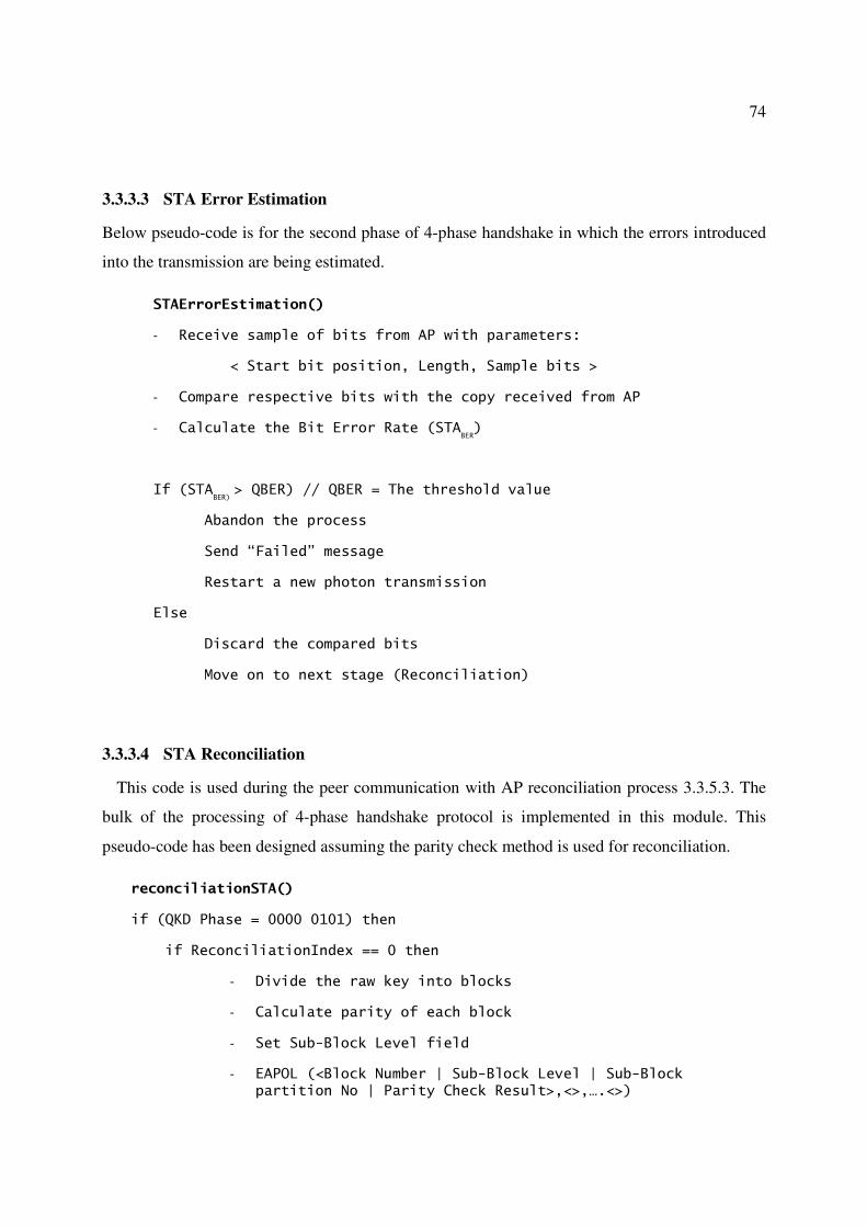
74
3.3.3.3 STA Error Estimation
Below pseudo-code is for the second phase of 4-phase handshake in which the errors introduced
into the transmission are being estimated.
STAErrorEstimation()
- Receive sample of bits from AP with parameters:
< Start bit position, Length, Sample bits >
- Compare respective bits with the copy received from AP
- Calculate the Bit Error Rate (STABER)
If (STABER)
> QBER) // QBER = The threshold value
Abandon the process
Send “Failed” message
Restart a new photon transmission
Else
Discard the compared bits
Move on to next stage (Reconciliation)
3.3.3.4 STA Reconciliation
This code is used during the peer communication with AP reconciliation process 3.3.5.3. The
bulk of the processing of 4-phase handshake protocol is implemented in this module. This
pseudo-code has been designed assuming the parity check method is used for reconciliation.
reconciliationSTA()
if (QKD Phase = 0000 0101) then
if ReconciliationIndex == 0 then
- Divide the raw key into blocks
- Calculate parity of each block
- Set Sub-Block Level field
- EAPOL (<Block Number | Sub-Block Level | Sub-Block partition No | Parity Check Result>,<>,….<>)

75
- ReconciliationIndex + 1 // increment the counter
else if (ReconciliationIndex == MaxSubLevel) or
(no more parity mismatches) then
- end of reconciliation
else
// A new EAPOL reconciliation frame has received
- compare the parities received against corresponding block(s)
- discard the last bit of the blocks compared
- identify the blocks/sub-blocks with parity differences
- bisect the blocks with parity differences
- Calculate parity of those sub-blocks
- Set Sub-Block Level field
- EAPOL (<Block Number | Sub-Block Level | Sub-Block partition No Parity Check Result>,<>,….<>)
- ReconciliationIndex + 1
end if
end if
end if
3.3.4 AP State transition diagrams
Similar to the changes done in STA state machine, necessary modifications have been made to
the AP as well. The AP state machine that has been modified in this research work with respect
to the QKD changes is shown in Figure 19 and Figure 20.
The following list describes the new states of the modified AP state machine used to support
QKD based key distribution.
AUTHENTICATION: This state is entered when an AuthenticationRequest is sent from
the management entity to authenticate a BSSID.
AUTHENTICATION2: This state is entered from AUTHENTICATION state or via
ReAuthenticationRequest.
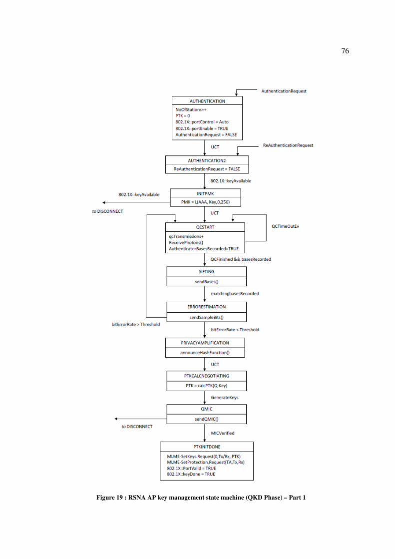
76
Figure 19 : RSNA AP key management state machine (QKD Phase) – Part 1

77
Figure 20 : AP State Machine (QKD Phase) - Part 2
DISCONNECT: This state is entered if an EAPOL-Key frame is received and fails to
verify Q-MIC. It sends Deauthentication message to the STA and enters INITIALIZE
state.
DISCONNECTED: This state is entered when Disassociation or Deauthentication
messages are received.
INITIALIZE: This state is entered via unconditional transfer from DISCONNECTED
state, when Deauthentication request event occurs, or when the station initialises.
INITPMK: This state is entered when the IEEE 802.1X backend AS completes
successfully. If a PMK is supplied, it goes to the QCSTART state, otherwise it goes to
the DISCONNECTED state.
PTKCALCNEGOTIATIING: This state is entered when the
PRIVACYAMPLIFICATION state is successfully completed. During this state, the
unique unconditionally secured key has been extracted.
PTKINITDONE: This state is entered once Q-MIC has been verified.

78
PRIVACYAMPLIFICATION: In this state, AP announces the hash Function to
recover the final key. It then unconditionally transfers (UCT) to
PTKCALCNEGOTIATING state.
QCSTART: This state deals with hardware apparatus to set up the photon transmission.
The AP receives the photons sent by the STA. Once the quantum transmission is finished,
the AP is in possession of quantum bases for each of the photons it transmitted.
QMIC: In this state Q-MIC is retrieved. The Q-MIC is send across to the STA for
verification.
SIFTING: The AP enters this state once the quantum transmission is finished in
QCSTART state. In this state AP executes sendBases and enters the
ERRORESTIMATION state.
STAQMIC: STA verifies the Q-MIC during this state. If the verification is successful, it
moves to PTKINITDONE state.
Respective AP’s new state machine variables are:
AuthenticationRequest: This variable is set to TRUE if the STA’s IEEE 802.11
management entity wants an association to be authenticated. This can be set when the
STA associates or at other times.
ReAuthenticationRequest: This variable is set to TRUE if the IEEE 802.1X AP
received an eapStart or 802.1X::reAuthenticate is set.
DeAuthenticationRequest: This variable is set to TRUE if a Disassociation or
Deauthentication message is received.
Disconnect: This variable is set to TRUE when the STA should initiate a
deauthentication.
NoOfStations: This variable keeps a count of number of APs present in a given time.
PTK: This variable is the current PTK.

79
802.1X::<xxx>: This variable is the IEEE 802.1X state variable xxx.
QCTimeOutEv: This variable is set to TRUE if the photons were not received.
bitErrorRate: This variable holds the quantum bit error rate calculated by the AP.
Threshold: This is the threshold quantum bit error rate allowed for a particular
transmission.
QCFinished: Set to TRUE upon completing the successful photon transmission.
basesRecorded: Set to TRUE when the bases of the photons are recorded correctly.
matchingBasesRecorded: This is set to TRUE once the matching bases between AP and
STA are verified.
GenerateKeys: This is set to TRUE upon extracting the key hierarchy from PTK.
3.3.5 EAPOL Frame Pseudo-codes for AP
AP uses EAPOL-Key frames to transmit QKD information to STA during the 4-phase
handshake protocol. Below EAPOL frame pseudo-codes describes those new procedures
involved.
3.3.5.1 Receive Photons
The pseudo code used to receive photons transmitted by the STA is shown below. It
communicates with its peer module as explained in section 3.3.3.1.
ReceivePhotons()
PMK = TRUE
QCSTART = TRUE
// receive photons
- Record the bases used
- Retrieve the respective bits
- qcTransmissions++

80
if (QCFinished) and
(qcTransmissions <= qcTransmissionsThreshold)
then
basesRecorded = TRUE
else if QCTimeOutEvt
then
EAPOL(reattemptTransmission)
Else
QCError // unable to setup quantum transmission
end if
QCSTART = FALSE
// Process the bases received.
// Discard the bases for which it is unable to determine
// a bit pattern
3.3.5.2 Send Bases
During the sifting process of 4-phase handshake, below pseudo code liaises with similar
module Received Bases as described in section 3.3.3.2 of STA.
sendBases()
- QKD Phase = 0000 0001
- Prepare list of bases used during photon reception
- Key Ack = 0
- EAPOL-Key<KeyData = bases_used>
3.3.5.3 AP Reconciliation
Below pseudo code performs the reconciliation of 4-phase handshake by communicating with
STA Reconciliation as discussed in section 3.3.3.3.
reconciliationAuthenticator()

81
if (QKD Phase = 0000 0101) then
if ReconciliationIndex == 0 then
Divide the raw key into blocks
// as per the reconciliation configuration parameters
// previously agreed
Calculate parity of each block
else if (ReconciliationIndex == MaxSubLevel) or
(no more parity mismatches)
then
end of reconciliation
else // A new EAPOL reconciliation frame has received
- compare the parities received against corresponding block(s)
- discard the last bit of the blocks compared
- identify the blocks/sub-blocks with parity differences
- bisect the blocks with parity differences
- Calculate parity of those b=sub-blocks
- Set Sub-Block Level field
- EAPOL (<Block Number | Sub-Block Level | Sub-Block partition No | Parity Check Result>,<>,….<>)
- ReconciliationIndex + 1
end if
end if
end if
GTK distributions are not discussed in this research due to time constraints. However GTK
distribution is similar to the establishment keys discussed so far.

82
3.3.6 Packet Level Changes
The IEEE 802.11 standard specifies changes to physical (PHY) and MAC layers of ISO OSI
protocol stack. This research mainly focuses on the changes to the distribution of key specified in
the IEEE 802.11i amendment. Since the proposed QKD based Wi-Fi protocol requires changes
to the existing IEEE 802.11i standard, some of the modifications required for beacon, probe
request and probe response massages are applied to physical and MAC layers. In addition the
EAPOL massage frames too have been used for 4-phase handshake communication with the use
of IEs.
IEEE 802.11i standard encompasses wide area in its protocol specification to implement
authentication and privacy aspects. Hence a special attention has been made to minimise the
impact to the existing IEEE 802.11i protocol during the implementation QKD based Wi-Fi
protocol.
Careful analysis of the existing IEEE 802.11i protocol shows that the existing communication
flows of 4-way handshake process can be altered to implement the QKD based key exchange.
Some of the fields used by 4 way handshake in EAPOL frames are modified to occupy QKD
specific information. The changes to the existing IEEE 802.11i standard are made in such a way
that it they will not change the existing frame formats. This is very advantageous as the same
frame can be reused to carry QKD information.
In addition, this approach requires physical implementation of photon transmission between
the AP and STA. Hence the proposed protocol requires switching between wireless channel
(classical channel) and quantum channel.
3.3.6.1 Modifications to 802.11 Association
The proposed modifications described in this section are indented to be used as the pre-
requisite for quantum channel. The beacon, probe request, probe response, association request,
association response, reassociation request and reassociation response frames are used to
communicate particulars related to quantum transmission. By agreeing a common set of QKD
specific parameters, AP and STA can proceed with the quantum transmission.

83
As explained in Chapter 2, Beacon frames are periodically transmitted by APs enabling them
to establish and maintain communication with STAs in an orderly fashion. APs transmit Beacon
frames containing all the information about the network periodically.
Before the communication begins, the AP and the STA has to agree upon a common set of
parameters in order to implement QKD for key exchange.
Those particulars are:
• QKD protocol: Informs types of QKD protocol supported (such as BB84, B92, SARG04,
Ekert91 etc) that the network can support.
• Quantum transmission keying rates
• Reconciliation method: Contains information about the type of reconciliation methods
(such as CASCADE, WINNOW) that the network is capable of supporting.
• Universal hash functions to be used during the privacy amplification
The AP has to tell STA about the type of services the network is capable of offering. In
IEEE 802.11 based WLANs, the beacon management frame contains all information about the
network.
Table 10 shows the information contained in the first 10 fields of Beacon management frame
[5], [54].

84
Table 10 : Beacon Frame Body (only the first 10 fields are shown)
Order Information
1 Timestamp
2 Beacon Interval
3 Capability Information
4 SSID
5 Supported Rates
6 FH Parameter Set
7 DS Parameter Set
8 CF Parameter Set
9 IBSS Parameter Set
10 Traffic Indication Map (TIM)
Out of these fields, 16 bit Capability information field contains information about capability
of the network. It carries particulars like type of network, polling, encryption details etc. Out of
these 16 bits, bit 12 is modified to carry information if the AP is capable of supporting QKD. In
the present IEEE 802.11 standard this bit has been not used. Modified Capability Information
frame is shown is Figure 21.
Figure 21 : Modified Capability information field of Beacon
STAs that seek to gain access to the wireless network, listen to Beacon transmitted by AP.
Upon seeing the matching parameters including QKD availability, STA responds with a Probe
Request. Probe Requests carry identification and configuration information to find an access
point supporting similar settings. STA may include Request Information Element in Probe
Request frame if the dot11MultiDomainCapabilityEnabled attribute is set to true. The format of
Request Information element has been discussed in Figure 4. These Element IDs will request
more specific information about the capabilities of AP via Request Information field. In case, if

85
any STA is not capable of supporting QKD, the QKD information present in the beacon can be
ignored and proceed with the normal process.
An AP that matches the SSID, data rates and channel information etc present in the Probe
Request, responds to the STA with Probe Response frame. Probe Response frame contains
similar data to that of Beacon as shown in Table 2 except for the TIM. The Probe Response has
a much richer structure than the Probe Request, and strongly resembles a Beacon. They both
serve similar functions to advertise the parameters under which the WLAN operates, and are
frequently referred to as a pair ("Beacon and Probe Response" or "Beacon or Probe Response").
Upon seeing the QKD parameter in the Capability Information field, any AP that support QKD
key exchange may respond with respective detail via Element IDs that embedded in Probe
Response frame.
When responding to the Probe Request message, AP includes those elements requested in the
Request Information elements (Figure 4).
Modifications include new element IDs to represent QKD parameters. The list of QKD
specific parameters that are required to implement key distribution are discussed below.
• QKD Protocol: Specify the QKD protocols such as BB84, B92, SARG04, six state etc
supported by the AP.
• Reconciliation protocols supported: Specify the reconciliation protocols such as
Winnow, Cascade etc supported by the AP.
• Privacy Amplification Algorithm: Hash functions that AP is used.
• Supported photon transmission keying rates.
• Polarization bases to be used.
A new element ID as shown in Table 11 has been created to represent the above QKD
parameters. This element ID is to be added to the Elements ID table described in Table 5Table
11. Unused Element ID 222 has been used for this new QKD Parameters.

86
Table 11 : New Element IDs for QKD
As shown in Figure 22, this new IE comprises 7 octets with 1 octet each for the Element ID
and the length while 5 octets for the respective information. The information field comprises
QKD Protocol, Reconciliation Method and Privacy Amplification algorithm, Photon
transmission rates and polarization bases.
Figure 22 : QKD Parameters Element Format
QKD Protocol field holds the types of QKD protocols that it supports. The values allocated for
QKD Protocols are:
0000 0000: BB84
0000 0001: B92
0000 0010: SARG04
0000 0011: Six State
0000 0100: Ekert91
All other values are reserved to hold any other QKD protocols.
The Reconciliation Method field holds types of methods that AP supports during reconciliation
phase of 4-phase handshake protocol. The bit allocations are:
0000 0000: Cascade
0000 0001: Winnow
All other values are reserved to hold any other QKD protocols.
87
Similarly the Privacy Amplification Algorithm octet contains information about the predefined
hash functions to be used during the privacy amplification phase of 4-phase handshake protocol.
These hash functions can be configured within the allowed 1 octet space accordingly.
The Photon Transmission Rates field holds the supported photon transmission keying rates
such as 1.25 Gbps, 10 Gbps etc. These values too can be configured as required.
Similarly Polarization Bases to be used for those photon transmissions can be specified in the
Polarization Bases field.
For an example:
0000 0000: 2 state
0000 0001: 4 state
0000 0010: 6 state
As discussed earlier, this element ID is included in the Probe Response or Beacon frames. In
addition to Probe Request and Probe Response frames, both Capability and IE fields are present
in Association Request (Table 6), Association Response (Table 7), Reassociation Request (Table
8) and Reassociation Response (Table 9) frames.
The use of QKD in this communication process is optional. If a client is not supporting QKD
or does not require the extra level of security offered by QKD, they can still move on with the
normal Wi-Fi process by ignoring the QKD information. In addition, standard EAPOL frames
have been used to carry QKD specific information. These frame formats do not need any
modifications. The data field is used to transmit QKD information relevant to each of the four
phases of 4-phase handshake protocol.
3.3.6.2 Modifications to EAPOL-Key Frame
EAPOL-Key frame carries the information exchange between STA and AP. In order to
accommodate 4-phase handshake protocol, several fields of EAPOL-Key frame have been
modified. Once again, these modifications to the fields have been carefully done to minimize the

88
impact to the existing communication. These modifications are applied only in the field level so
that the overall frame structure remains intact.
Type of modifications done in the existing IEEE 802.11 protocol under this project is mainly
concentrated on the key distribution. To be specific, the existing 4-way handshake has been
replaced by QKD based 4-phase handshake. To accommodate these changes few of the existing
EAPOL, frames have been modified. These modifications do not alter any of the existing
encryption formats. This means the existing coding and authentication methods of EAPOL frame
structure is not impacted. Thus the proposed modifications still use the same authentication and
encryption of EAPOL.
Figure 23 shows the modified EAPOL-Key frame with QKD specific changes. Modifications
have been made to Key Information, Key Nonce and Key Data fields.
Modifications to “Key Nonce” field: The Nonce values used in the existing 4-way handshake
protocol are not required in the 4-phase handshake protocol. Hence the Key Nonce field has been
replaced with a new field called QKD Phase [6]. QKD Phase field holds information of what
phase of 4-phase handshake protocol is in progress. These are the four phases of 4-phase
handshake protocol: Sifting, Error Estimation, Reconciliation and Privacy Amplification.
Furthermore, the Key Nonce field has 32 octets. But for QKD Phase, only one octet is enough.
Hence the Key Nonce field has been split into two fields with one octet to occupy QKD Phase
while the rest of the 31 octets have been set as reserved.
Possible values of QKD Phase:
� 0000 0001: Send/Receive bases. Used to indicate when the STA is sending the bases used
during the quantum transmission. Both STA and AP set this bit during the exchange of
bases.
� 0000 0011: Error estimation. Used to indicate that the EAPOL frame contains set of
sample bits for comparison to estimate the errors introduced during the quantum
transmission. The “data” field of this frame contains “start bit position” and the
respective bits being compared.

89
� 0000 0101: Reconciliation. Used to indicate the reconciliation phase of 4-phase
handshake is in progress.
� 0000 0111: Privacy Amplification. Used to indicate that the privacy amplification process
is in progress.
Figure 23 : Modified EAPOL-Key Frame to implement QKD [6]
Modifications to “Key Data” field: There are no specific changes to Key Data field. As the
existing IEEE 802.11 protocol operates, this field is of variable length and carries additional
information relevant to current communication flow. With respect to QKD modifications, Key
Data field holds data as per each of the QKD Phase.
Modifications to “Key Information” field: Three fields of Key Information bit layout as
described in Figure 10 have been modified for QKD protocol. These bits are “Key Type”, “Key
Ack” and “Install”. Figure 24 depicts the new modified Key Information bit layout.

90
Figure 24 : Modified Key Information bit layout
� Quantum Transmission Re-attempt (bit 2): In the present IEEE 802.11, this field is
known as Key Type. It is used to indicate if a new quantum transmission is required or
not.
Possible values are:
0 : Default value
1 : Restart quantum transmission
� Key Ack (bit 7): This bit is set if a response is expected to the message being sent and
clear otherwise.
� Error Estimation Result (bit 6): This field is called as Install in the current IEEE
802.11. It used to indicate the error estimation of QKD transmission.
Possible Values are:
0 : Error estimation Failure
1 : Error estimation Success
3.3.6.3 Modifications Required for Reconciliation Phase
The reconciliation phase of 4-phase handshake performs the bulk of the processing as it needs
to correct errors present in the raw key. The actual communication flows involved in this phase
depend on the type of reconciliation process being used. In this project, the parity check based
bisection method has been used [11] as the reconciliation protocol. When compared to other
reconciliation protocols such as Cascade, Winnow etc, the parity check method involves more
processing to recover the final key after correcting errors. The reason for using the parity check
method is to test this proposed protocol under the worst possible conditions.

91
In the parity check reconciliation protocol, STA and AP agrees upon a random permutation,
and applies it to what remains of their respective raw keys. Next they partition the remnant key
into blocks of length L. For each of these blocks they compare overall parity checks, making sure
each time to discard the last bit of the compared block. Each time an overall parity check does
not agree, STA and AP initiate a binary search to locate the error. That is, they bisect the block
into two sub-blocks then discard the right most bit of each sub-block. They continue their
bisective search on the sub-block for which their parities are not in agreement. This bisective
search continues until the erroneous bit is located and deleted. They then continue to the next
block. This process is repeated for the all the blocks spanning across the raw key. Finally when
for some fixed number of consecutive repetitions, if no error is found, they assume that to a very
high probability, the remnant key is without any error. This key is the reconciled key.
To implement this reconciliation process in the EAPOL-Key frames, a novel method has been
used as described below. All these changes have been applied to Key Data field of EAPOL-Key
frame.
At first, during the reconciliation process of the 4-phase handshake, value of EAPOL-Key
frame is set to 0000 0101. As described earlier, this is to indicate that the QKD process has
entered into the reconciliation phase. Next is to include the parity check information in the Key
Data field. For this, the Key Data field has been structured as:
< Block Number | Sub-Block Level | Sub-Block Partition Number | Parity Check Results >
Where:
Block Number: Number of the main block.
Sub-block Level: If the main block parity check failed, that block will be bisected
and perform the parity check again. The “Sub-block Level” field specifies the level of
bisection of each main block. If the main block is bisected once, Sub-block Level =2,
if it is bisected twice Sub-block Level =3 and so on.
Sub-block Partition Number: Whenever a mismatch in parity of block/Sub-block is
observed, that particular block/Sub-block is bisected. This Sub-block Partition
Number field holds the Sub-block partition number of each of the sub blocks.

92
Parity Check Result: This field holds the results of parity checks of each of the sub
blocks.
0: parity result = odd
1: parity result = even
The Key Data frame has been structured to carry these information in the new format as shown
in Figure 25.
Figure 25 : Key Data field values of EAPOL frame during reconciliation phase of QKD
Both AP and STA partition their raw keys into blocks of equal length. For each of these
blocks, they perform the parity check and calculate parity. During the first message containing
reconciliation information, the STA constructs the EAPOL frame by populating “block number,
Sub-Block Level, Sub-block partition number, parity result of that block” for each of the blocks
of the key. When the key is partitioned for the first time, “Sub-Block Level” field is set to 1.
STA calculates the parity of each of the blocks and populates the “Parity Check Result” field
along with the respective block/Sub-block position of each of the block in the EAPOL frame.
The STA then sends the EAPOL frame to the AP. AP in turn compares the parity results of each
block against its copy of the raw key. If a parity mismatch is found, the respective block is
bisected and the parity is calculated for the new sub-blocks. These parity checks are populated in
the respective “Parity Check Result” fields. The AP then constructs the respective EAPOL
message and sends to the STA. This process continues until there are no more parity mismatches.
Table 12 shows how each field of this protocol is constructed.

93
Table 12 : Reconciliation parity check EAPOL frame details
Block
Number
Sub-block
Level
Maximum Number
of partitions Parity Check Results
n 1 1 R1-1
n 2 2 R2-1, R2-2
n 3 4 R3-1, R3-2, R3-3, R3-4
n 4 8 R4-1, R4-2, R4-3, R4-4, R4-5, R4-6, R4-7, R4-8
Where:
n : Main block number
Rb-x : Parity check result of Sub-Block Level “b”, sub block “x”
As an example, consider a particular block number “B” of the raw key as shown in Figure 26.
Figure 26 : Example of reconciliation via EAPOL (where; A = AP, S = STA)
Say Block B = 6 (i.e. 6th block of the partitioned key). Assume the parity check of this block
resulted in odd parity (assume the odd parity is represented as bit 0). The corresponding filed

94
carrying the block information in the EAPOL frame is represented by: [6,1,1,0], Where Block
No = 6, Sub-Block level = 1, Sub-Block partition no = 1, Parity check result = 0.
In the EAPOL frame, this information in the “Key Data” field will populate as:
[0000 0110 | 0000 0001 | 0000 001|0]
Figure 27 shows the bit level details of this information.
Figure 27 : Key Data for block 6
Once this information has reached the AP, it compares its respective block data against the
ones just received. Assume this block produces even parity at the AP. However, the parity check
of the same block in the STA had produced odd parity. Hence the AP sees the parity mismatch
and bisects the block B (B1 and B2) and calculates the parities of the 2 sub-blocks. Assume the
parity results of B1= 1 and B2 = 1. Thus the respective block (and sub block) data of the “Key
Data” of EAPOL frame will represent as:
[0000 1010 | 0000 0001 | 0000 001|0] [0000 1010 | 0000 0001 | 0000 010|1]
Once this frame reaches the STA, it finds out that the increment in Sub-block shows parity
mismatch and locates which sub-block partitions are in error. It bisects the corresponding sub
block and compares the parity. In this example, a mismatch occurs in sub-block B2, hence it
bisects it into B2-1 and B2-2. The parity of these two sub blocks are calculated and respective
EAPOL frame is sent to the AP. This process continues for all the blocks of the raw key.
Once a full cycle through the raw key is completed, this process continues for some fixed
number of consecutive iterations. During those iterations, if no error is found, they assume that
the remnant key is without any error. By this way the reconciled key is obtained. The decisions
on whether to proceed with the repetitions of parity checks and when to stop the repetitions are
taken by the AP.

95
Once the reconciliation is completed, AP and STA can verify if their reconciled keys are
identical. This verification is optional. For this verification, AP sends a string of random text as a
challenge. This random text is taken from the sample of bits from PMK. The STA uses its
version of the reconciled key to encrypt the text. It then sends the encrypted text back to the AP.
AP in turn decrypts this text using its version of the reconciled key. If they match, the two
versions of reconciled keys are identical and they move to the next phase of 4-phase handshake
protocol, privacy amplification. In case, a mismatch is found, they start another round of parity
check.
Figure 28 shows the described parity check based reconciliation process for proposed Wi-Fi
key distribution protocol including the optional key verification.
In this protocol, the parity check is not done one by one for each of the blocks. Instead, parities
of all the blocks are performed simultaneously. Hence in one full cycle the whole key can be
covered. This makes the process efficient as it saves multiple communication cycles.
Similar to the implementation of parity check, other reconciliation protocols like Cascade,
Winnow etc too can be introduced into the EAPOL-Key communication. Depending on the
nature of the operation, respective modifications need to be done. Implementations of other
reconciliation protocols are not in the scope of this research.

96
Figure 28 : Reconciliation Process using Parity Check

97
3.3.7 Quantum communication channel
Quantum transmission is solely handled via quantum apparatus present in AP and STA. There
is no involvement of wireless channel controlling the quantum transmission. Once the photon
transmission starts, STA moves to STAQCSTART state as described in section 3.3.2. Quantum
channel starts soon after seeing the EAP Key message delivering the PMK to AP and STA. Also,
the quantum channel ends immediately after the desired photons are transmitted from STA to
AP.
During the photon transmission, STA and AP have to be in line-of-sight. Since the target
network range is limited to around 200 meters, achieving communication within line-of-sight is
practically possible.
The quantum transmission proceeds with the information agreed between AP and STA during
IEEE 802.11 association process. As discussed in section 3.3.6, Beacon, Probe Request and
Probe Response messages exchange QKD specific information that are required for the quantum
transmission. This information includes QKD protocol, bases to be used, quantum transmission
rate etc.
During the quantum channel, the quantum transmitter of STA transmits polarised photons
towards the photon receiver of AP. The STA records the random bit string and the random bases
it used to polarise the photons. Similarly AP too records the random bases used to convert each
bit received and also the converted bit pattern. Since STA initiates the quantum transmission, it
has accurate information on the actual bit string used and the bases used to polarise those bits.
However in the other hand, AP merely guesses the bases to recover bits. Since the bases used by
STA and AP are not identical, the bit string recovered at AP is not identical as well. AP’s
recovered bit string contains many errors and unrecovered bits.
As soon as the agreed number of photons is transmitted, STA stops sending its photon
transmission. This results in the end of quantum transmission. Soon after this transmission ends,
the hardware hands over the control back to the wireless channel.

98

99
Chapter 4 Implementation
The proposed protocol requires modifications to several areas, mainly in the EAPOL wireless
communication messages. In addition to the wireless channel, it has to cater for the quantum
channel as well. In the 4-phase handshake protocol, there are four main phases to implement.
Since this research only focuses on the key distribution process, extra efforts have been taken to
find ways of implementing the modifications in line with the existing protocol. Further, in order
to analyse the protocol, this implementation has been designed to support performing
experimental analysis under various conditions. The design also allows different input data to see
the behaviour. Thus the amount of implementation work required is quite significant.
This chapter discusses the implementation of the proposed QKD based Wi-Fi protocol
considering all these aspects. The focus of this chapter is the implementation of quantum channel
and the 4-phase handshake protocol of classical channel.
4.1 Implementation of Quantum Channel
The quantum channel plays a major role in the proposed QKD Wi-Fi protocol. The accuracy of
transmission always helps to recover identical secret keys at either end much faster and enables
the rest of the Wi-Fi communication to proceed smoothly.
As of now, there are no commercially available Wi-Fi specific wireless devices that are
equipped with quantum transmitters or receivers. Hence in this research work the quantum
transmission has been established as a separate project aligned to an existing QKD research work
[4], [22], [23], [24]. In this particular research, the quantum transmissions have been practically
demonstrated under various scenarios over large distances over free space. Since this approach
provides much needed quantum transmission, the same set up has been chosen to implement the
quantum channel of QKD based Wi-Fi protocol. This has no impact on the experimental set up
as the quantum and classical channels operate independently. Basic high level set up of quantum
channel between AP and STA is shown in Figure 29. Just for this illustration, the channel

100
switches have been shown as located outside AP and STA. In reality the channel switches reside
inside STA and AP itself.
Figure 29 : High Level Set Up of Quantum Channel [10]
As shown in Figure 29, the first step of QKD is the quantum transmission established between
AP and STA. During this one way communication, STA sends a series of polarized photon
representing the key towards AP. As soon as the quantum transmission completes, the quantum
channel is switched to classical channel where the 4-phase handshake protocol takes place to
recover the secret key. The classical channel is two-way communication in which both AP and
STA interact with each other to obtain the key.
Figure 30 shows the schematic diagram of the QKD system set up with illustrations to internal
hardware. At STA, laser pulses are generated by vertical cavity surface emitting lasers
(VCSELs) and attenuated into a single photon level [19]. The polarization states of photons are
set by polarisers as per the corresponding protocol (B92, BB84 etc).

101
Figure 30 : Schematic Diagram of QKD System [19], [30]
Afterwards photons are combined and sent through a non-polarizing beam splitter (NPBS). If
the chosen QKD protocol uses four states (e.g.: BB84), the polarisers Pol. 0A, 0B, 1A, and 1B
are oriented to 0°, 90°, +45°, and -45° respectively. If the QKD protocol contains only two states
(e.g.: B92), polarisers 0A and 1A, will be used. At AP, polarization controllers recover the
polarization state of photons with respect to their original state at STA. The 3-dB coupler
randomly chooses the detection base and the polarization beam splitter (PBS) helps to determine
the key value. Finally the photons are detected by single photon detectors (APDs). Two APDs,
0A and 1A, are used for B92, while four APDs are used for BB84. The scope of this research is
limited to SARG04 QKD protocol (which is a slight variation of BB84), but can be extended to
support other QKD protocols.

102
In the proposed QKD based Wi-Fi protocol, when the STA is about to start photon
transmission, the state gets changed to STAQCSTART. At this moment the software sends a
signal to the quantum controlling device to initiate the photon transmission. This software API
call includes the number of photons to be transmitted in order to recover the final key that would
have sufficient length to retrieve key hierarchy.
Before the quantum channel begins, both parties agreed on set of QKD specific parameters
such as QKD protocol, transmission rate etc that are required to set up the quantum transmission.
These parameters are negotiated during the 802.11 association as described in section 3.3.6.1.
During the photon transmission, the photon transmitter and receiver maintain their line-of-
sight. The hardware apparatus performs the transmission with clocks synchronized so that the
STA and AP can sample bases accurately. As soon as the photons transmission completes, the
quantum channel seizes. At this stage, the quantum hardware hands over the control back to the
classical channel, which is wireless channel in this case, to proceed with the rest of the
communication. This marks the exit of new transition state STAQCSTART.
There are several outcomes at the end of the quantum transmission. At the STA side, it records
all the random bases it used as well as the original bit string that sent across to AP. In this
implementation, both these types of information are stored in an in-memory buffers written in
C++ language. One of the buffers stores the key bit string used in the form of unsigned integer.
For example, say the transmitted bit string is: 10010111001001010, the buffer stores the bit
pattern as it is, but with a chosen delimiter separating each bit. While recording the bits in this
implementation, coma (,) has been used as the delimiter.
Thus the buffer will hold the bit string as: 1,0,0,1,0,1,1,1,0,0,1,0,0,1,0,1,0
The second buffer holds the bases used to polarise these bits. This too stores the bases as
unsigned integer with mapping to the respective bases.
The SARG04 uses four non-orthogonal bases to polarise the photons. Table 13 shows the
mapping used to represent bases in the buffer containing base used.

103
Table 13 : Bases Representation in STA Buffer
Base Represented by unsigned
integer in buffer
00 1
450 2
900 3
1350 4
Thus this buffer would hold random bases that used to map those integer values. Similar to the
former buffer, this too uses a delimiter to separate the bases.
As an example, this buffer would hold: 2,1,4,4,3,1,1,4,4,3,3,4,2,1
The AP too maintains similar buffers: one to hold the random bases used while the other holds
retrieved bit string. The buffer holding bases is very similar to the one used at STA. However the
buffer used to hold the retrieved bits could contain empty spaces separated by the delimiter used
(commas). This is because, due to the errors introduced during the transmission and also due to
the mismatch of bases used, there could be instances where STA is unable to decide a particular
bit specifically. Such occurrences will result in empty spaces (shown as “� ” below).
Thus the buffer will look like: 0,� ,1,0,0,1,� ,� ,1,0,0,� ,1,� ,� ,� ,1,0,1
Thus, there are four main outputs at the end of the quantum transmission:
1. Random bases used by AP
2. Retrieved bit string by AP
3. Random bases used by STA
4. Retrieved bit string by STA
All this information is captured into in-memory buffers by AP and STA. The information
contained in these buffers will be the input to subsequent 4-phase handshake protocol taking
place in the wireless channel.

104
In addition to the main QKD link that has been running over long distance in free space,
University of Canberra optical laboratory also consists of the experimental setup as shown in
Figure 31. This set up has been used to generate more specific test data with various error levels
that has been fed into the simulation model described in section 4.3. A filter has been used to
simulate environmental conditions such as dust, moisture etc.
Figure 31 : QKD Experimental Setup
4.2 Implementation of Wireless Channel
IEEE 802.11 standard defines Medium Access Control (MAC) and Physical Layer (PHY)
Specifications for Wireless LANs. Hence the modifications proposed in this QKD based Wi-Fi
protocol is directly applied to the Physical and MAC layers and also in EAPOL. Therefore the
implementation requires writing low level software that would facilitate the modifications

105
proposed. However the modifications needed in the existing 802.11 protocol are limited only to
few specific sections where the 802.11 association and 4-way handshake is taking place. At the
same time, this solution is designed to allow users to give an option to use QKD if they require
unconditional security for their communication session. Hence the proposed solution should be
able to support both the existing 802.11 protocol and the proposed QKD based Wi-Fi protocol.
Further, as of now there are no Wi-Fi certified devices that support quantum transmission.
Because of this, it is not necessary to write the whole 802.11 protocol in order to implement the
proposed modifications.
The scope of new changes to the existing IEEE 802.11i protocol is focused only on the
association and authentication phases. The implementation work is mainly focused on those
communication processes. For the implementation, several options have been considered.
One of the options was to attempt to implement the STA and AP communication process using
Microsoft Native WiFi product. The Native Wifi application programming interface (API)
functions has two purposes: to manage wireless network profiles and to manage wireless
network connections. The API elements are exposed by the Auto Configuration Module (ACM).
The Native Wifi automatic configuration component configures, connects to, and disconnects
from wireless networks [59]. The Native Wifi API, designed for C/C++ developments, contains
functions, structures, and enumerations that support wireless network connectivity and wireless
profile management. The aim was to run STA on Windows XP while AP/Authentication Server
(AS) to run on Windows Server 2000. However the proposed protocol involves modifying the
existing Wi-Fi packet formats to implement proposed QKD based Wi-Fi protocol. Those packet
changes have been discussed in Chapter 3. Unfortunately, Native Wifi API does not allow
programmers to do field level changes needed in the proposed QKD based Wi-Fi protocol.
Hence this option had to be abandoned.
Another option was to use the Network Simulator (ns-2) [60]. ns-2 is a discrete event simulator
targeted at networking research. ns-2 provides substantial support for simulation of TCP, routing,
and multicast protocols over wired and wireless (local and satellite) networks. It is widely used
in the simulation of routing and multicast protocols, among others, and is heavily used in ad-hoc
networking research. ns-2 supports an array of popular network protocols, offering simulation
results for wired and wireless networks alike. However due to the same reason as for Native Wifi,

106
ns-2 APIs too was found to be not flexible enough to allow packet level changes to implement
the proposed QKD based Wi-Fi protocol.
As the next option, the use of Simulink was explored. This approach is discussed in the next
section 4.3.
4.3 Simulink Approach
The nature of modifications required in low level frame formats of the existing IEEE 802.11
standard is quite interesting. The existing communication flow should be changed starting from
the association up to the authentication. During this process the secure key is established and
then proceeds with the existing communication flow as usual. Hence the tool to be used for the
simulation should be flexible enough to accommodate those modules and also to feed different
simulation inputs as well when observing the behaviours at various levels.
The analysis has shown that Simulink [61], [63] offers the much needed flexibility with respect
to the simulation work of this proposed QKD based Wi-Fi protocol. Simulink, developed by
MathWorks, is a commercial tool for modelling, simulating and analysing multidomain dynamic
systems. Simulink allows programming interfaces to control various inputs according to the
required scenarios.
This solution has been implemented as a software development process using the C++
language. C++ as the development language offers several advantages. C++ offers APIs to
directly use low level routine calls to talk to lower level layers to OSI protocol stack. Being an
object oriented language, the modularizations can be done efficiently. This research work also
proposes using Multi Agent Systems (MAS) as a future enhancement. This approach is discussed
in Chapter 6. The same C++ codes can also be used during the MAS implementation. Most
importantly, unlike Java, C++ can be used in conjunction with Simulink S-Functions to do the
simulation work. Hence the design is to write C++ functions to implement each of the main tasks
and sub tasks and directly use them to convert into Simulink compatible code with the use of S-
Functions.

107
An S-function (system-functions) is a computer language description of a Simulink block. S-
functions can be written using several languages including C++ and allows adding blocks to
Simulink models [63]. S-functions use a special calling syntax that enables interaction with
Simulink's equation solvers. This interaction is very similar to the interaction that takes place
between the solvers and built-in Simulink blocks. The form of an S-function is very general and
can accommodate continuous, discrete, and hybrid systems. Hence the C++ programs developed
for Wi-Fi modifications can serve not only for current applications, but also for future
applications such as MAS.
To make the implementation less complex, the main communication flows that require
modifications have been split into a number of key modules. These modules include: transmitter
and receiver functions, packet assembly/disassembly functions, modules involving QKD
protocol etc. Since the main focus is on the implementation of proposed QKD based Wi-Fi
protocol aligned with existing IEEE 802.11 protocol, functionalities of each of the 4-phase
handshake have been analysed to be represented via individual modules.
Main modules of QKD based key exchange in Wi-Fi solution can be categorized as:
• EAPOL Wireless communication
• 4-phase handshake: Sifting, Error Estimation, Reconciliation, Privacy Amplification
Since the main aim of this research is focused on implementing the proposed QKD based
protocol for Wi-Fi networks, the software developments have been done to implement the 4-
phase handshake. Hence the focus is to use Simulink model for wireless transmitting and
receiving components without any hardware involvement. This will help to analyse and compare
the impact of proposed QKD based Wi-Fi protocol with respect to the actual IEEE 802.11i
protocol on the key distribution process.
4.3.1 QKD Software Implementation
This section describes the implementation design of the C++ class structure used in the four
phases of 4-phase handshake protocol. All four phases of QKD need to push their information
via EAPOL messages in order to establish a communication session between AP and STA. The

108
structure has been designed to represent each of the QKD phases as a separate C++ class. The
class structure designed for AP is shown in Figure 32. Since the all modules of 4-phase
handshake have to interact with wireless network, a wrapper class has been written to establish
communications. This wrapper class IEEE 802.11 Wrapper facilitates the communication
between QKD classes and lower layer modules. This wrapper class is the only interface for the
QKD modules towards the wireless channel.
The four stages of 4-phase handshake have been designed to implement as individual classes
representing each phase. The base classes of these four phases are SiftingBase,
ErrorEstimationBase, ReconciliationBase and PrivacyAmplificationBase. The actual
implementation of these base classes are defined underneath as respective “impl” classes. For
simplicity, only some of the internal C++ functions are shown in Figure 32. These
implementation classes consist of several private classes to execute the required functionalities of
each phase. Only the main such classes are shown here.
In addition, there is another main class BitStreamController which looks after the key string at
APs side. All four implementation classes of 4-phase handshake have a common access to
APBitStreamController. Having such a class to take care of the key at AP’s side is an advantage
as it is this key getting updated several times at each phase. All these key updates are handled via
BitStreamController and APBitStream classes. Since the 4-phase handshake executes in
sequential mode, the final key of the AP is not altered by those modules simultaneously, making
the process less complex.
APQuantumBases class provides functions to siftingImpl support polarise bases management.
Those functionalities include fetching the bases, construction of the buffer during sifting phase.
The ErrorEstConfig class stores and provides data that are required for error estimation to its
parent class ErrorEstimationImpl.
Since reconciliation being the most critical phase of entire protocol, there are many supporting
classes defined to facilitate the operation. The class ParityCheck performs parity calculations by
fetching the required block from the buffer. The IndexBufferMgr does the management of buffer
containing the bit stream. With indexing the buffer reconciliation process makes more efficient.

109
BiscetBock class performs additional support functions to IndexBufferMgr. The BisectAlgo class
keeps a record of all levels of bisections that the bit stream buffer has gone (to support the
method described in section 3.3.6.3).
This class structure has been designed in such a way that each stage of 4-phase handshake can
be analysed and operates individually to see how they behave. Further, the C++ functions of
those classes are also designed in such a way that they do not tightly bind to any of the main
processing modules, which is quite useful during the simulation as well as during the
experimental evaluation and analysis.
Figure 32 : C++ Class Structure of AP

110
It is also noted that this design enables less complex modifications as the functionalities of the
whole system have been split into several individual functions. Thus any modifications to the
relevant phase could be done with minimal effort without having any impact on the overall
protocol. For example, if a new reconciliation protocol is to be used instead of the existing parity
check method, only the class structure for reconciliation needs to be replaced keeping the other
class hierarchies intact.
Since both STA and AP execute similar set of functionalities during each of the stages of 4-
phase handshake protocol, similar class structure has been used for the STA side as well. This
STA class structure is shown in Figure 33. These classes of AP and STA do peer to peer (P2P)
communication during the 4-phase handshake protocol. Though the function names look
identical, the internal activities of the functions are different as they operate most of the time on
request – response basis. During sifting, error estimation and privacy amplification phases, the
protocol directly follows the predefined sequence of communication messages. However for the
reconciliation process, though the procedure is predefined, the execution needs some decision
making steps to be adopted by the functions. This involves a number of parity check cycles to be
performed, length of the blocks to be bisected etc.

111
Figure 33 : C++ Class Structure of STA
It is noted that since the 4-phase handshake protocol executes sequentially, software modules
representing each of the handshake phase have been implemented in isolation, which makes it
possible that C++ class and their functionalities have been modelled into Simulink S-Functions
for simulation and analysis.
Simulink models of each of the 4-phase handshake protocol are described below.

112
4.3.1.1 Sifting Model
Simulink sifting model implements the sifting phase of the 4-phase handshake protocol. This
model is responsible for removing bits that have been recorded against the incorrect bases. The
STA first generates a random string of bits as the initial key. During the quantum transmission,
this key is transmitted by the STA towards the AP as polarised photons. SARG04 QKD protocol
uses four states as in BB84. Those four different random bases used to interpret each of the
random bits during the quantum transmission have been recorded in a memory buffer. Thus the
main inputs to the sifting model at the STA is the random bit steam used as the initial key and the
random bases used to transmit those bits via photons.
At the AP’s side, it uses random bases to convert the photons received into respective bit
sequences. Hence AP too has its own version of random bases used and the initial key retrieved
is stored into memory buffers.
The internal activities of AP’s Simulink model can be split into two main sections:
1. To extract information on the bases used and construct the EAPOL frame to be
transmitted to STA
2. Upon receiving the matching bases from STA, reconstruct its key bit sequence
In the sifting model, AP constructs the EAPOL frame containing the bases it used for photon
transmission. This information is constructed as per the changes proposed to EAPOL frames in
Chapter 3. The Simulink model that represents the sifting phase of AP is shown in Figure 34.
This figure contains the models for transmit and receive which are shown as two separate models
as the aim of this section is to discuss only the sifting model. The complete model is described in
section 4.4.

113
Figure 34 : Simulink Model of Sifting Phase for Access Point
The 802.11 Transmitter Subsystem is responsible for transmitting the constructed frames with
respective 4-phase handshake information. Similarly 802.11 Receiver Subsystem receives the
communication frames from the other end. These two Simulink subsystems are common for all
models of 4-phase handshake.
The programming code used to implement the sifting phase comprises several main functions.
For the transmit side, the S-Function sfun_ap_siftingtx prepares bases to be transmitted to STA.
It takes bases used from Bases of AP (the input file apbases.mat) which consists of the random
bases recorded during the photon transmission. These bases are to be used to populate the Key
Data field of the EAPOL frame. The output of this S-function carries all the information required
for constructing the EAPOL frame to be sent to STA. During the EAPOL frame construction, the
new parameter “QKD Phase” is set to 0000 0001 to indicate the sifting phase is in progress. This
output is then fed to the 802.11 transmitter. The second Simulink model (bottom model of Figure
34) processes the information received from STA. The receiver of EAPOL frame feeds the data
as the input to this function. The main functionalities of this function are:
• Unpack and extract the data received from STA
• Verify the bases received against the based used
• Reconstruct the random key by keeping only the bits that match with the correct bases
STA is used
These S-Functions includes the code written in C++. Figure 35 shows the main C++ function
used for sifting implementation at AP. This function is responsible for populating the bases and
bits used into buffers.

114
Figure 35 : Main C++ Function used for Sifting Implementation at AP (scaled image)

115
Similarly the STA’s sifting phase consists of processing the information received from AP.
When the EAPOL frame from AP is received by the STA, it unpacks the frame and retrieves the
bases. It then feeds the data to S-function of STA. The Simulink model that represents the sifting
phase of STA is shown in Figure 36.
Figure 36 : Simulink Model of Sifting Phase for STA
The main functionalities of the error estimation model are:
• Unpack EAPOL frame
• Compare matching bases
• Reconstruct buffer containing the bases with matching bases to be sent to AP
• Reconstruct the buffer with the bits corresponding to the matching bases
The S-function sfun_sta_siftingcomparebases compares the received bases from AP with its
version of the bases. It then reconstructs the EAPOL information containing the matching bases
to be sent to AP via stun_sta_reconstruct. At the same time it updates the key bits of its buffer to
leave only the bits with matching bases.
The full process of the sifting phase consists of two communication flows only. During these
two messages, the AP and STA agree upon a set of bits from the main key sequence which are
recorded against the same bases. After this stage, the use of the second buffer used to hold bases
is no longer required, so the respective memory is released.

116
4.3.1.2 Error Estimation Model
The implementation of the Simulink Error Estimation model is described in this section. The
implementation of the error estimation phase also comprises two EAPOL communication
messages. The Simulink model for STA has been implemented by several S-functions.
The Simulink model of STA is shown in Figure 37. The S-Function sfun_staerrest takes a
random sample of the key bits recorded at the STA. It then outputs the sample bits along with the
start bit position and other necessary data to construct the EAPOL frame. During the EAPOL
frame construction, the new parameter QKD Phase is set to 0000 0011 to indicate the error
estimation phase is in progress.
Figure 37 : Simulink Model of Error Estimation Phase for STA
Figure 37 shows two models used to transmit and receive at STA. During the transmit model,
STA picks up a random subset of bits from its key (STA Bits) and sends it across to AP.
The receiving path carries the error estimation result from AP. Based on this result, the S-
Function sfun_stadecision decides how to proceed afterwards. Assuming the result is success,
which means the error level is acceptable; sfun_staproceed removes the bits revealed from the
local copy of the bit stream and reconstructs the memory buffer. If the response failed, the
memory is released and waits for the new quantum transmission.

117
The corresponding Simulink model of sifting phase for AP is shown in Figure 38.
Figure 38 : Simulink Model of Error Estimation Phase for AP
The main functionalities of this AP’s model are:
• Compare sample bits
• Calculate Error Rate (R)
• Compare the result R with QBER
• Make the decision to proceed or to start a fresh quantum transmission
If the result is success, discard revealed bits from its key
• Output the result to be sent to STA
When AP receives the EAPOL frame transmitted by STA carrying sample bits,
sfun_aperrorest compares a local copy of the key bits against the bits received. The S-Function
sfun_aperrestdecision retrieves the bit error rate (QBER) based on the information used during
the photon transmission. Since the threshold levels of quantum transmission vary for different
types of quantum transmission, the configuration file qkdconfig.mat is used to retrieve the
necessary values. Based on the bit error rate calculated, a decision is made whether to proceed or
start a fresh quantum transmission. This decision is then transmitted to the STA. If the error level
is within the allowed range, sfun_apreconstructbits deletes the bits revealed and reconstructs the
local copy of bit stream.

118
4.3.1.3 Reconciliation Model
The section describes the reconciliation model of Simulink. Reconciliation is the most critical
phase of 4-phase handshake protocol in which the key is extracted after removing all the errors.
In this simulation, the bisect algorithm using parity check method has been used. This is because
it consumes most of the resources compared to other reconciliation protocols. Thus the worst
case scenario has been simulated. The Simulink model for reconciliation at AP side is shown in
Figure 39.
Figure 39 : Simulink Model of Reconciliation Phase for Access Point
Main functionalities of this model are:
• Set parameter QKD Phase = 0000 0101
• Split the key into blocks
• Calculate the parity of each block
• Construct the EAPOL frame
• When the reply frame is received:
o Compare the parity of each block
o If a mismatch is found, bisect the block and calculate parity of each sub-block
o Construct the EAPOL frame

119
• Repeat the process until there are no more errors
• Perform more parity checks to verify that there are no more errors
This model implements the new bisect algorithm developed as part of this project. The
operation of this algorithm in EAPOL frames has been described in detail in section 3.3.6.3.
During the first cycle, sfun_blocksplitter splits the key into blocks of equal length. It keeps a
record of block sizes, sub-block levels, parities of each block that are required to calculate the
block sizes. During subsequent cycles, this function processes each sub-block by comparing with
the sub-blocks received from STA. The sfun_parity calculates the parities of new sub-block and
sfun_construct does the construction of final details that are required to form the EAPOL frame.
This information is then passed to the transmitter to be sent to STA.
STA too execute similar processes to verify the parities of blocks and sub-blocks. Simulink
model of STA is identical except for minor changes when initiating its first cycle. In addition, it
takes its own copy of key bits as the input. The Simulink model of STA is shown in Figure 40.
Figure 40 : Simulink Model of Reconciliation Phase for STA

120
The Verify Bases Subsystem checks the overall state of the key string. It decides how accurate
the derived key bits are after removing errors through parity checking. It decides how long the
parity checking needs to continue and when to stop. The main C++ function used for the parity
check algorithm is shown in Figure 41.
This function is responsible for:
• Comparing the parities
• If any mismatch is found, it bisects the respective block
• Calculates parity of each new sub-block
• Prepares partition size, sub-block level as per the reconciliation algorithm (section
3.3.6.3)
• Sends those information to other party (by calling the APIs created in the main class)

121
Figure 41 : Main C++ Function for Parity Check Algorithm (scaled image)

122
4.3.1.4 Privacy Amplification Model
The Simulink model of privacy amplification is described in this section. The final phase of
the 4-phase handshake protocol is the privacy amplification. The aim of this phase is to eliminate
possible information leaks to eavesdroppers by implementing a chosen hash function. The
Simulink model of privacy amplification for AP is shown in Figure 42.
As soon as the reconciliation phase is completed, AP sends STA the information about the
hash function to be applied using sfun_ap_hashfunction. At the same time AP applies the
selected hash function to its version of the key and reconstructs it after removing bit as per the
hash function.
Figure 42 : Simulink Model of Privacy Amplification Phase for AP
The Simulink model for privacy amplification for STA is shown in Figure 43. STA in turn
applies the hash function and reconstructs its key via sfun_sta_hashfunction. Like sifting and
error estimation, there are only two communication messages involved in this phase.
Figure 43 : Simulink Model of Privacy Amplification Phase for STA

123
4.4 Full Model of the System
Previous sections have described the operation of each individual phase of the 4-phase
handshake protocol. The main reason to have these four phases is to investigate how these phases
behave in isolation. With this kind of model, the performance analysis can be done effectively.
The full Simulink models of AP and STA comprises merging of respective sub models
described in section 4.3.1. The 802.11 Transmitter Subsystem and 802.11 Receiver Subsystem act
as the main interface between AP and STA.
The full Simulink model with all four phases integrated for AP is shown in Figure 44.
Figure 44 : Full Simulink model of Access Point
The 802.11 Receiver Subsystem receives all communication frames and directs to the
respective model for further processing. Since the 4-phase handshake protocol operates in a
sequential manner, each sub model is executed one after the other. The processed outputs are fed
into the 802.11 Transmitter Subsystem to be sent to STA. All sub modules update the key of AP

124
to recover the final secret key. The execution of each individual phase has been described in the
previous sections.
Figure 45 shows the full Simulink model for STA. This model too comprises the Simulink
models described in previous sections. The overall operation of this full model is similar to that
of AP described in Figure 44.
Figure 45: Full Simulink model of STA

125
Chapter 5 Evaluation of Results
The proposed protocol changes have concentrated on the key distribution of existing 802.11
protocol. Hence the experimental analysis is focused mainly on the areas that are impacted by the
modifications involving QKD. The results obtained through Simulink models as described in
section 4.3 have been analysed in this chapter. For more sophisticated analysis, each stage of 4-
phase handshake has been set up as a separate model. This provides the ability to see how each
section behaves under various input conditions. Also the overall system containing combined
models has also been analysed.
The length of PTK for CCMP is 384 bits. Hence the aim is to obtain a 384 bit long final key
after removing all the errors introduced during the quantum key exchange. Considering the
number of erroneous bits introduced during the transmission, quantum channel should make sure
to send a sufficient number of photons that would be long enough to recover the final Q-Key
(PTK) after removing the errors. Section 2.9.3 described the possible error levels that could be
associated with quantum transmission. It was shown that in the worst possible case if an
eavesdropper eavesdrops on every bit of the key, the AP’s error rate could increase to 37.5% (as
explained in 2.9.3).
One remarkable feature of quantum cryptography is its ability to detect eavesdropping by the
incident of an unnaturally high quantum bit error rate [145]. Thus any eavesdropping will cause
a significant amount of errors in the key. In addition, environmental conditions and poor quality
photon apparatus too could contribute to the errors. However, the impact of environmental
conditions on the quantum transmission is somewhat limited. This is mainly because Wi-Fi
networks are mostly located indoors and also the coverage area is small. Hence when compared
to outdoor networks spanning long distances, they are not heavily impacted by environmental
conditions such as sun, air turbulences etc. Hence for simulation purposes, the maximum error
rate of 40% has been chosen as the upper bound.

126
Using four phases of classical channel aims to identify and eliminate errors introduced during
the quantum channel. In fact, the elimination of errors means the removal of bits that have been
interpreted incorrectly. The removal of bits during the four phases of classical channel happens
in several ways:
• In the sifting phase, bits that are recorded against the incorrect bases get deleted.
• During the error estimation phase, the set of bits used to calculate the error rate also get
removed from the key. The reason to remove this particular set of bits is that those have
been publicly revealed. It is done for security purposes and does not necessarily imply
all those bits had errors.
• In the reconciliation phase all of the erroneous bits get deleted. Generally a majority of
the bits gets discarded at this phase.
• Finally, another set of bits gets deleted during the privacy amplification phase
depending on the hash function applied. Unlike other phases, the bits deleted do not in
fact have errors. The aim behind the removal of errors in this phase is to eliminate
possible leakages of information to eavesdroppers.
In order to simulate scenarios with different levels of errors in the input key, test data has been
created in such a way that each key string contains a specific percentage of errors. For an
example, suppose the AP and STA have raw keys 1 1 0 0 1 0 1 1 0 1 and 1 0 0 1 0 0 1 0 0 1
respectively. That is, four of the bits are in error (erroneous bits are shown as bold and
underlined). Thus the error rate is 40%. In order to analyse behaviour of the system at different
error rates, several sets of key data containing error levels of 10%, 20%, 30% and 40% have been
created for simulation purpose. Table 14 shows the total number of bits available to recover the
final key after removing bits at various levels of errors. The Initial key length refers to the length
of the key before removing errors. Or in other words it is the key obtained at the completion of
quantum communication.

127
Table 14 : Bits available to recover the final key after removing errors
These error levels and initial key lengths have been used throughout this chapter for analysis
and simulation work. To maintain consistency and accuracy of results, the same set of data with
different error rates has been used in all scenarios. All these simulations have been done in 4-
phase handshake protocol.
The next few sections analyse the behaviour of each of the 4 phases of 4-phase handshake
protocol against different input data.
5.1 Analysis of Sifting Phase
The aim of this section is to observe the behaviour of the sifting phase of 4-phase handshake
protocol using the simulation model described in section 4.3.1.1. Main functionalities being
tested and analysed here is the recovery of the raw key by eliminating the bits extracted against
incorrect bases.
During the sifting phase, the AP takes the bases used during quantum transmission and the
respective bit stream as the inputs. Due to unavailability of Wi-Fi certified apparatus that support
quantum transmission, these input data has been generated via the free space quantum channel
established as a separate project [4]. At the end of quantum transmission, both parties are in
possession of two flat files containing the bases used and the respective bit stream of the key
transmitted. In an ideal scenario where the Wi-Fi certified devices support quantum
communication, these data will be processed on the fly via device memory rather than using flat
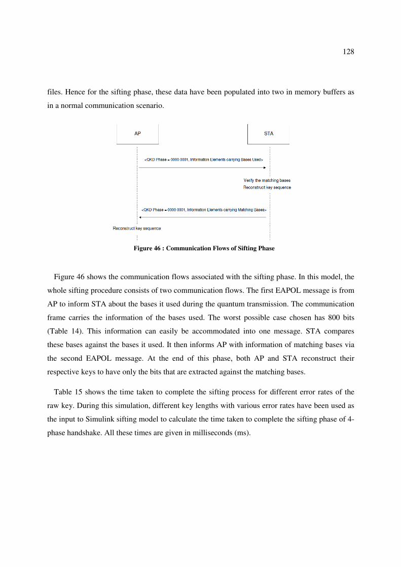
128
files. Hence for the sifting phase, these data have been populated into two in memory buffers as
in a normal communication scenario.
Figure 46 : Communication Flows of Sifting Phase
Figure 46 shows the communication flows associated with the sifting phase. In this model, the
whole sifting procedure consists of two communication flows. The first EAPOL message is from
AP to inform STA about the bases it used during the quantum transmission. The communication
frame carries the information of the bases used. The worst possible case chosen has 800 bits
(Table 14). This information can easily be accommodated into one message. STA compares
these bases against the bases it used. It then informs AP with information of matching bases via
the second EAPOL message. At the end of this phase, both AP and STA reconstruct their
respective keys to have only the bits that are extracted against the matching bases.
Table 15 shows the time taken to complete the sifting process for different error rates of the
raw key. During this simulation, different key lengths with various error rates have been used as
the input to Simulink sifting model to calculate the time taken to complete the sifting phase of 4-
phase handshake. All these times are given in milliseconds (ms).
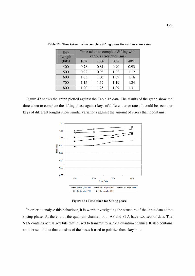
129
Table 15 : Time taken (ms) to complete Sifting phase for various error rates
Key
Length
(bits)
Time taken to complete Sifting with
various error rates (ms)
10% 20% 30% 40%
400 0.78 0.81 0.90 0.93
500 0.92 0.98 1.02 1.12
600 1.03 1.05 1.09 1.16
700 1.15 1.17 1.19 1.24
800 1.20 1.25 1.29 1.31
Figure 47 shows the graph plotted against the Table 15 data. The results of the graph show the
time taken to complete the sifting phase against keys of different error rates. It could be seen that
keys of different lengths show similar variations against the amount of errors that it contains.
Figure 47 : Time taken for Sifting phase
In order to analyse this behaviour, it is worth investigating the structure of the input data at the
sifting phase. At the end of the quantum channel, both AP and STA have two sets of data. The
STA contains actual key bits that it used to transmit to AP via quantum channel. It also contains
another set of data that consists of the bases it used to polarize those key bits.

130
AP also holds similar sets of data: One set of data contains the interpreted bits obtained when
extracting bits from the received photons. The other set of data is the random bases it used to
extract the key bits.
During the first message (Figure 46) of sifting phase, the AP informs STA about the bases it
used. Since those bases are used to represent every single bit of the transmitted key, number of
key bits and the bases are identical. This means for every key length of Table 15, the same
number of bases is transmitted to STA via the first communication message. At the STA all these
bases are compared against the bases it used. Thus the longer the key length, the more time it
takes for comparison of bases. Whenever a mismatch of a base is found, corresponding bit is
getting eliminated from STA’s key. At the same time, STA prepares a list containing the
positions of bases that matched. This information is transmitted to AP in the second EAPOL
communication of Figure 46.
This means, the longer the key, the longer the time it takes to complete sifting as both parties
need to go through each key/bases combination. The time for completion is also increased if the
error rate is high. This is the reason that keys of higher error rates take more time to complete the
sifting phase. At the same time irrespective of whether the bases are matched or mismatched,
they have to go through each and every key bit of their respective keys. This results in all lines of
Figure 47 behaving in a similar linear manner during the sifting phase. Since all processing takes
place on the fly, the time consumption has been minimized. Overall, on average it could be seen
that the whole sifting phase can be completed in around 1ms.
5.2 Analysis of Error Estimation
The main task of the error estimation process is to estimate the errors of the mapped key string
after quantum transmission. As pointed out in section 2.9.2.2, the mapped key string contains
errors arising from various reasons. It is essential to obtain an accurate estimation as at this stage
it has to decide whether to proceed or start a new transmission. Hence inaccurate results could
prove costly for both time and resources of the system had they decided to proceed if the error
level is above the threshold. Thus a correct decision by accurately estimating the errors is
essential to proceed with the rest of the protocol.

131
The decision of error estimation takes the process of communication either forward or
backward to the quantum transmission. The former case takes place if the calculated error rate is
less than or equal to the quantum bit error rate (QBER) of the quantum transmission. The QKD
research work done by the Centre for Advanced Telecommunications and Quantum Electronics
Research (CATQER) at the University of Canberra has established several QKD setups over
different distances in free space [27], [4], [28], [29], [146], [147], [148]. QBER levels between
4% - 8.1% have been achieved during those demonstrations. Table 16 shows the QBER values
obtained during free space quantum transmission between Telstra tower and Wallaroo Field
Station.
Table 16 : Summary of Polarised Photon Propagation Trial Data [27]
Analyser
Setting /
Degree
Position
Angle /
Degree
Comments Count
Rates / CPS
Peak pulse amp. = 5.0V
80 0 Mean photon number per pulse: (1.1 ± 0.07)E4
35 45 <np> = 6.0 (5.0 ± 0.3)E3
350 90 QBER = 6.0% 300 ± 20
Peak pulse amp. = 4.0V
80 0 Mean photon number per pulse: 1700 ± 70
35 45 <np> = 0.95 830 ± 50
350 90 QBER = 5.1% 42 ± 10
Peak pulse amp. = 3.5V
80 0 Mean photon number per pulse: 710 ± 40
35 45 <np> = 0.44 370 ± 20
350 90 QBER = 8.1% 30 ± 5
Peak pulse amp. = 3.0V
80 0 Mean photon number per pulse: 400 ± 30
35 45 <np> = 0.25 220 ± 10
350 90 QBER = 7.7% 17 ± 5

132
The QBER values stated are mostly due to the analyser misalignment, transmitter
depolarization, analyser extinction ratio limits and background photon flux leakage. These data
have been taken as the input to the proposed QKD based Wi-Fi protocol simulations.
5.2.1 Error Estimation – Successful Scenario
During this scenario, STA randomly pick up a subset of bits from its key to be used for error
estimation and constructs the EAPOL packet along with the start bit position and QKD Phase
parameter. AP in turn does the calculations by comparing the respective bits, calculating
(equation (3) of section 2.9.2.2) the error rate R, compares it with the QBER of the quantum
channel.
For a successful communication:
4EFJCFE=AK A;;?; ;E=A *�+ L ���� (5)
Figure 48 shows the communication flow diagram of successful error estimation scenario.
Figure 48 : Error Estimation – Successful Scenario
In the first flow of Figure 48, STA sends a random sample of bits obtained from its key. AP
then extracts this information and compares against the corresponding bits of the key. It then
calculates the error rate (R) and checks to see if R is within the allowed limits as per the equation
(5) above. Since in this scenario, the error level is within the acceptable limits, AP informs STA
the result via the second flow of Figure 48.

133
Yet again the same set of test data has been used to analyse the performance of the error
estimation phase. During these simulations, error rates varying between 10% and 40% have been
used for several key lengths to obtain the time taken for error estimation. Table 17 shows the
statistics recorded against these input values.
Table 17 : Time taken to complete Error Estimation – Successful Scenario
Key
Length
(bits)
Time taken to complete Error Estimation
with various error rates (ms)
10% 20% 30% 40%
400 0.63 0.72 0.80 0.97
500 0.68 0.79 0.91 1.01
600 0.72 0.83 0.98 1.08
700 0.81 0.90 1.01 1.14
800 0.97 1.02 1.11 1.27
The line graph plotted against these data is shown in Figure 49. The analysis shows that the
overall performances of error estimation are similar for different key lengths and error levels. As
expected, when the size of the key and the error rate increase, the time taken to complete the
error estimation also increases, almost linearly.
Figure 49 : Time taken for Error Estimation

134
The most time consuming operations of this phase are the comparison of sample bits and the
reconstruction of the key by removing the bits revealed. It should be noted that both parties have
to go through the process of reconstructing their respective key. Thus in order to improve the
efficiency, once AP calculated the bit error rate, rather than reconstructing its version of the key,
AP sends the result to STA. Since in this scenario, the result is a success, both parties can
reconstruct their respective keys in parallel, saving time. However, when compared to the size of
the sample bits being compared, the time taken for overall error estimation is very low.
5.2.2 Error Estimation – Unsuccessful Scenario
If the error rate comparison fails, there is no point in proceeding with the rest of the 4-phase
handshake protocol due to two reasons. Firstly, a sufficient number of bits that are required to
break the key may have leaked to an eavesdropper. Secondly, due to atmospheric or other
impacts, large numbers of errors may have been introduced into the transmission. Both scenarios
require further processing of QKD protocol to be abandoned and start a new quantum
transmission. Figure 50 shows the communication flow for the unsuccessful error estimation
scenario.
Figure 50 : Estimation – Unsuccessful Scenario
The operational procedure of Figure 50 is similar to the successful scenario described in Figure
48 with the only difference being the result of second flow indicates a failure. They then switch

135
to quantum channel for a fresh transmission. If the result of error rate is unsuccessful, they do not
need to proceed with the key reconstruction since the rest of the process has been aborted. If this
happens, they clear the key buffers allocated for the key and release memory. Since the key
reconstruction is not required, the simulation results for unsuccessful error estimation show that
the total time for this scenario is nearly halved.
Table 18 : Time taken to complete Error Estimation – Unsuccessful Scenario
Initial Key
Length
Time taken to complete unsuccessful Error
Estimation with various error rates (ms)
10% 20% 30% 40%
400 0.25 0.30 0.34 0.45
500 0.29 0.35 0.42 0.48
600 0.34 0.40 0.51 0.59
700 0.40 0.46 0.53 0.62
800 0.49 0.54 0.61 0.74
Table 18 shows the time taken for this process. If this step happens, the time taken thus far has
been a waste. However, even if this happens the amount of time lost is considerably small. As
per the data collected in Table 18, the maximum time taken is 0.74ms obtained for 40% of error
rate for key length of 800 bits. However, it is highly unlikely such a high error rate happens for a
quantum transmission as most of the practical QKD systems have achieved much lower error
rates. Even the quantum transmissions attempted under the parallel project achieved QBER
values less than 8.1% (Table 16). All these transmission have been carried out over distances
spanning many kilometres in free space with unpredictable atmospheric conditions.
5.2.3 Improved Error Estimation for Wireless QKD
It is essential to estimate the error rate as accurately as possible to avoid possible waste of time
and resources. Had the error estimation been done incorrectly and allowed to proceed, it would
only be detected when the final Q-MIC values are verified. By then the whole 4-phase handshake
would have taken place and they would need to restart the process again.
It is worth investigating how the errors may have distributed within the quantum key. The
errors introduced into the key, by environmental, eavesdropping or by any other means, do not
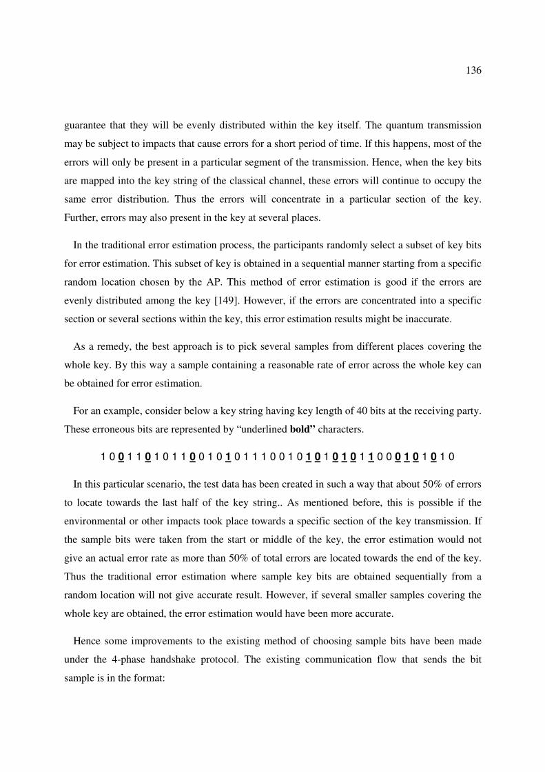
136
guarantee that they will be evenly distributed within the key itself. The quantum transmission
may be subject to impacts that cause errors for a short period of time. If this happens, most of the
errors will only be present in a particular segment of the transmission. Hence, when the key bits
are mapped into the key string of the classical channel, these errors will continue to occupy the
same error distribution. Thus the errors will concentrate in a particular section of the key.
Further, errors may also present in the key at several places.
In the traditional error estimation process, the participants randomly select a subset of key bits
for error estimation. This subset of key is obtained in a sequential manner starting from a specific
random location chosen by the AP. This method of error estimation is good if the errors are
evenly distributed among the key [149]. However, if the errors are concentrated into a specific
section or several sections within the key, this error estimation results might be inaccurate.
As a remedy, the best approach is to pick several samples from different places covering the
whole key. By this way a sample containing a reasonable rate of error across the whole key can
be obtained for error estimation.
For an example, consider below a key string having key length of 40 bits at the receiving party.
These erroneous bits are represented by “underlined bold” characters.
1 0 0 1 1 0 1 0 1 1 0 0 1 0 1 0 1 1 1 0 0 1 0 1 0 1 0 1 0 1 1 0 0 0 1 0 1 0 1 0
In this particular scenario, the test data has been created in such a way that about 50% of errors
to locate towards the last half of the key string.. As mentioned before, this is possible if the
environmental or other impacts took place towards a specific section of the key transmission. If
the sample bits were taken from the start or middle of the key, the error estimation would not
give an actual error rate as more than 50% of total errors are located towards the end of the key.
Thus the traditional error estimation where sample key bits are obtained sequentially from a
random location will not give accurate result. However, if several smaller samples covering the
whole key are obtained, the error estimation would have been more accurate.
Hence some improvements to the existing method of choosing sample bits have been made
under the 4-phase handshake protocol. The existing communication flow that sends the bit
sample is in the format:

137
<Start bit location, length>
This has been changed to:
<Start bit location1, length1>, <Start bit location2, length2>, <Start bit location3, length3> ….
This modification can easily be accommodated in the proposed 4-phase handshake protocol
with IEs carrying the additional sample data.
Considering the above example, if the traditional error estimation has taken place, there is a
good probability that it will take sample bits from the middle of the key. If this happens, the
calculated error rate would have deviated heavily from the actual error rate as most of the errors
are concentrated towards the end of the key. With the new proposed method, this can be easily
avoided as it would take three samples (say) of 4 bits from 10th
, 20th
and 30th
bit positions.
Figure 51 shows the result of some simulations carried out to compare the traditional error
estimation and the proposed error estimation used in 4-phase handshake protocol. During this
simulation a key of length 500 bits with 20% actual error rate has been used. Test data has been
created such that nearly 12% of its errors are concentrated between 350 to 500 bits, while
remaining 8% distributed within the rest of the key length (0 to 350 bits).
This figure shows the data collected by executing both methods (traditional and improved
version) on several attempts to estimate the error rate. Using the traditional method, several error
estimation cycles have been run with 25 bit length sequential samples taken starting from 50,
100, 150, 200, 250, 300, 350, 400 and 450 bit locations. For each of the sample error rate is
calculated and the graph (traditional) is plotted. In comparison, error estimation has been
conducted by using the proposed method with small samples of 5 bit lengths taken from different
parts covering the whole key. As per the test data in this scenario, the expected error rate is 20%
(0.2). It could be seen that the proposed method always shows near accurate error estimation as
its samples are taken from different parts of the key. The calculated error rate is closer to the
actual 0.2 mark.

138
Figure 51 : Comparison of Traditional and Proposed Error Estimation
In contrast, the error estimation results of the traditional method show fluctuating results
depending on the location in which the sample is taken. This is obvious since in this particular
example, 12% of errors (out of a total 20%) are located between bits 350 to 500. Thus any
sample taken from this area would show higher error rates. The error rate for the sample taken, at
450 bit mark went even higher than the actual error rate. This is because the sample test data had
several errors located in this particular segment.
The most important advantage of the improved version is, regardless of how the errors are
distributed in the key, it gives more accurate error rates than the traditional method.
5.3 Analysis of Reconciliation
Reconciliation is the most critical phase of 4-phase handshake protocol where STA and AP
remove all the errors present in their respective keys to recover the final identical key. Unlike
other phases of 4-phase handshake protocol, the number of communication flows involved in the
reconciliation process cannot be known in advance. This is because the number of cycles needed
to complete this phase depends on the amount of errors present in the key and also the type of
reconciliation protocol being used.

139
As described in section 3.3.6.3, a novel method has been used to implement the reconciliation
process using bisect algorithm. Out of the many widely used reconciliation methods available
today, the bisect method consumes more messages flows. The main reason to choose this method
is to observe the behaviour of 4-phase handshake protocol in the worst possible circumstances.
During this algorithm, the main key is first divided into blocks of equal length. These blocks are
then bisected during the parity checks to locate the errors. Thus, unlike other phases of 4-phase
handshake protocol, reconciliation has block size as an extra parameter. These blocks get
bisected whenever a parity mismatch on any of its blocks is found. Hence it does not guarantee
that the initial block size will remain constant throughout the reconciliation process.
The time taken to complete the reconciliation process in this simulation model depends on
several key factors:
• length of the main key
• length of the initial block size of the partition
• number of cycles the parity check will run for
Several scenarios have been attempted to estimate the time taken to complete the reconciliation
process against different key lengths. As listed in Table 19 (section 5.3), keys with different
levels of error rates with different key lengths have been fed into the Simulink model. The time
taken to complete reconciliation under these input conditions for an initial block size of 8 bits is
shown in Table 19. The Key Length refers to the key obtained after error estimation, while initial
block size or block size refers to the size of the block that the main key was divided initially. This
initial block size gets reduced each time the respective block is bisected.

140
Table 19 : Time Taken for Reconciliation for Block Size 8
Key Length
Time taken (ms) to complete Reconciliation
with various error rates (for block size = 8)
10% 20% 30% 40%
400 4.1 4.21 4.35 N/A
500 4.34 4.47 4.57 5.09
600 4.51 4.65 4.75 5.23
700 4.71 4.92 5.09 5.46
800 4.9 5.07 5.26 5.77
Figure 52 shows the line graph plot against these data. The scenario with key length of 400 bits
with 40% of error rate is not considered as a valid data as described under the analysis of Table
14. The results show that when the error rate is low, the final key can be recovered much
quicker. The maximum key length tried in the simulations has the length of 800 bits, which is a
good upper limit as it can produce a final key of 480 bits at 40% error rate. This is quite
sufficient to obtain the final PTK of length 384 bits for CCMP. It is evident that for larger key
lengths with high error rates, more time is taken to complete the reconciliation. This is mainly
because under such circumstances the initial key needs to go through several cycles of parity
check. For larger key lengths and high error rates, bisect algorithm needs to go through a number
of sub levels of bisections in order to locate the bits that are in error. This invariably is more time
consuming for the reconciliation process. However it must be noted that error rates of 20% and
over is highly unlikely to happen. The QKD project has achieved error rates below 8.1% (Table
16). Even if such situations occur, they will be detected during the error estimation phase,
causing the quantum transmission to be attempted again. The scenarios over 20% of error rates
have been considered just to simulate the worst possible scenarios.

141
Figure 52 : Key sizes Vs Time for block size = 8
The most notable observation is that all lines of Figure 52 show similar behaviour to various
error levels and key lengths. The main conclusion is that regardless of the key length, for smaller
error rates, the reconciliation phase could be completed well within a reasonable time frame by
recovering the final key.
Further analysis has been carried out to find out how the initial block size could impact on the
performance of the reconciliation process. During this analysis, time to complete the
reconciliation has been calculated for various error levels for a fixed key length of 500 bits.
Figure 53 shows how initial block sizes interact with the performance of reconciliation.

142
Figure 53 : Time to complete Reconciliation for Key Length = 500 bits
It could be seen that the smaller the bisect block size, the quicker the completion of the
reconciliation process. With initial block sizes of 4, 8 and 16 reconciliation completes within
4ms time frame which is quite acceptable considering the amount of work involved in removing
the errors. The main reason to this result is that when the initial block size is smaller, the errors
can be located more quickly. However, much smaller initial block sizes are not advisable since
the parity results are publicly revealed via classical channel. If the blocks are small, the parity
results revealed could lead any third party to guess the bits of the blocks [150].
Further, if a parity mismatch is found, then the respective block gets bisected and eventually
another round of parity verification is added to the overall communication. With a smaller initial
block size, the number of sub-blocks required is considerably low. Hence the reconciliation can
be completed more quickly. Once the block size exceeds 16, it could be seen that the amount of
time required for reconciliation increases significantly. The main reason for this observation is
that the number of cycles needed to process the full key length is considerably large. Larger
block length will subsequently bisect into more and more sub-blocks hence parity check requires
more time to complete.

143
Other notable observation is when the error level is high (such as error level of 40%), it takes a
significant amount of time for reconciliation irrespective of the block size. This is because the
entire key is required to process right up to the smallest sub-block level, hence consuming more
time for completion.
Similar analysis has been done to estimate the time to complete reconciliation for different key
lengths and block sizes by keeping the error rate constant at 30%. Figure 54 shows the
simulation analysis for these input conditions. Yet again it could be seen that for smaller block
sizes, regardless of key length, reconciliation shows much improved performances. For initial
block sizes 4, 8, 16, 24, 32 and 64 the performances show similar behaviour. However for block
length of 128 bits, the time consumption becomes significantly larger. Again, the reason for this
behaviour is that the raw key requires several rounds of communication cycles to locate the
errors.
Figure 54 : Time to complete Reconciliation for Error Rate of 30%
This outcome once again confirms the previous evidence that for smaller key lengths and
smaller initial block sizes, the performance of reconciliation shows better results Hence it could
be concluded that block sizes between 8 to 16 shows much improved results for the
reconciliation phase of the 4-phase handshake protocol. Initial block length of 24 too is
acceptable as it is in the marginal levels with respect to the time taken for completion.

144
5.3.1 Performance of Proposed Bisect Reconciliation Protocol
The parity check based bisect algorithm used for reconciliation generally consumes several
communication cycles. However, in this research, this algorithm has been used in efficient ways
to minimise resources and computation times. The proposed method of using the bisect method
in 802.11 protocol has been described in section 3.3.6.3. Under normal circumstances, parities of
blocks of the key are compared sequentially. This invariably wastes time working through each
block one at a time. In the proposed method, parities of all the blocks are compared
simultaneously rather than going through them sequentially. This is achieved by structuring the
frame format to accommodate all the blocks with their respective block number, sub-block level,
Sub-block Partition Number and parity result.
In the sequential method, once the main key (after error estimation) is divided into sub blocks,
the parities of each of these blocks have been compared one after the other until the whole key is
compared. Then it goes through several more cycles before the final key is recovered after
removing the errors.
However, in the proposed method, once the key is divided, parities of all the blocks are
compared simultaneously. This is achieved by storing the previous states of each block and
compares them with the latest state. In the next cycle, blocks that have parity mismatches get
bisected and their parities get compared simultaneously. During each cycle the number of blocks
to be compared gets reduced as most of the blocks have been cleared by the process. Due to this
reason, the proposed method completes the parity check much faster than that of the traditional
method.
The performance of the proposed protocol has also been analysed as shown in the Figure 55. In
this simulation, times taken to complete the parity check using sequential and the proposed
methods have been compared. For a key of 600 bits long having an 30% error rate with initial
block size of 16 bits has been tried to find out number of communication cycles that are required
to obtain the final key.

145
Figure 55 : Comparison of Traditional and Proposed Methods
For a key length of 600 bits with initial block length of 16 bits, the main key gets partitioned
into 37 blocks (600 / 16 = ~37). Parity check starts from this number of blocks in both methods.
With the proposed method, all 37 blocks get checked for parity. Only the blocks that have parity
mismatches will progress to the next round. This process continues until all blocks have no mode
parity mismatches. As per the simulations done in Figure 55, the proposed method completes
reconciliation of 4 rounds in 4.99ms, whereas the sequential method takes 11 rounds in 22ms. It
could be seen from the results, the proposed protocol completes much faster than that of the
traditional parity check method.
5.4 Analysis of Privacy Amplification
During privacy amplification, the key gets further reduced by applying a selected universal
hash function to eliminate whatever information that may have leaked to an eavesdropper. The
amount of information an eavesdropper might know is based on the sifted bit error rate
determined during reconciliation and is entirely applied to potential eavesdropping, rather than
distributing that error rate between eavesdropping and system losses [36].
The same set of input conditions used in the previous stages has been tried in this phase as
well. The main input conditions for privacy amplification are the reconciled key, error rate and

146
the security parameter (section 2.9.2.4). The security parameter has been kept to 20 bits during
the simulations. The performance analysis done against privacy amplification is shown in Figure
56.
Figure 56 : Time taken for Privacy Amplification
From Figure 56, it can be seen that the performance behaviour of privacy amplification
remains similar across different key lengths. When the error rate is low, it is evident that privacy
amplification gets completed much quicker as the amount of processing on the key is low. In
addition to error rate and length of the key, security parameter and the hash function being used
also have an impact on the performance. Most of the time consumption during this phase
depends on the type of universal hash function being used. The hash function requires some
mathematical calculations to compute how the bits are removed to eliminate the information that
may have leaked to eavesdroppers. For this simulation work, a well established universal hash
function [37],[38], [117] has been used.
During this phase, AP and STA execute the universal hash function agreed during the 802.11
association (Section 3.3.6.1). All the processing of this phase takes place within AP and STA as
they executes the hash function and restructure the existing copy of the key to generate the final
secured key. In fact the privacy amplification process terminates at this stage as the final key is
derived. However, the final goal of obtaining the key hierarchy in terms of 802.11 is not yet
finished. Hence a few more additional steps as described in Section 3.3.1 are required. Though
the communication flows involving these additional steps do not really belong to privacy

147
amplification, for completeness of the proposed 4-phase handshake protocol, those messages
have been counted as part of this phase.
Since the required key length for CCMP is 384 bits, any extra bits of this secured key will be
stripped off to obtain the final key of 384 bits. This key is PTK in wireless terms. Once PTK is
known, the rest of the key hierarchy containing KCK, KEK, TK and GTK is derived. Finally Q-
MIC is calculated and the message integrity is verified via the last two communication flows.
These are the only communication flows involved as per the extended privacy amplification.
Thus the performance of the privacy amplification includes these additional flows.
It could be seen that most of the processing done during privacy amplification takes place
within the AP and STA itself. This improves the security aspects as it limits any intrusions by
adversaries.
5.5 Analysis of Overall QKD based Wi-Fi Protocol
The performance of the overall protocol can be analysed in two ways: The quantum channel
used to transmit photons and the classical channel used to recover final secured key. Main focus
on this simulation work is to implement the software component of the classical channel. This
software component also depends on the type of QKD protocol being used. Further, the type of
reconciliation protocol contributes to the performance of the overall system.
Considering the classical channel, this research has used SARG04 as the QKD protocol with
bisection algorithm using parity check for reconciliation. The first, second and fourth QKD
phases, namely, sifting, error estimation and privacy amplification respectively, do not consume
heavy resources as the amount of activities involved is limited to a few bit comparisons or
restructuring the key etc.
In contrast, the bisect algorithm based parity check involves some considerable amount of
processing during the reconciliation phase. As described in section 5.3, many different scenarios
with several input data have been used for simulations. The variations of chosen reconciliation
protocol are the length of the key, initial block size of the partition and error rate. However the
first, second and fourth phases do not have any such variations that would impact the overall

148
process. Hence from the classical channel point of view, the results of the variations of the
reconciliation phase have been analysed below.
During the analysis of the reconciliation process in section 5.3, the results show that for
partition, a block size of 8 or 16 is ideal for the starting block length. Table 20, Table 21, Table
22 and Table 23 show the total time taken for the whole 4-phase handshake at different key
lengths for error rates 10%, 20% and initial block sizes 8 and 16 bits.
Table 20 : Total time for proposed protocol (Error Rate=10%, Initial Block size=8 bits)
Key
Length
Time for
Sifting
Time for Error
Estimation
Time for
Reconciliation
Time for
Privacy
Amplification Total time
400 0.78 0.63 4.1 0.79 6.30
500 0.92 0.68 4.34 0.82 6.76
600 1.03 0.72 4.51 0.90 7.16
700 1.15 0.81 4.71 0.97 7.64
800 1.20 0.97 4.99 1.03 8.19
Table 21 : Total time for proposed protocol (Error Rate=20%, Initial Block size=8 bits)
Key
Length
Time for
Sifting
Time for Error
Estimation
Time for
Reconciliation
Time for
Privacy
Amplification Total time
400 0.81 0.72 4.21 0.83 6.57
500 0.98 0.79 4.47 0.91 7.15
600 1.05 0.83 4.65 1.01 7.54
700 1.17 0.90 4.92 1.08 8.07
800 1.25 1.02 5.07 1.20 8.54

149
Table 22 : Total time for proposed protocol (Error Rate=10%, Initial Block size=16 bits)
Key
Length
Time for
Sifting
Time for Error
Estimation
Time for
Reconciliation
Time for
Privacy
Amplification Total time
400 0.78 0.63 4.41 0.79 6.61
500 0.92 0.68 4.52 0.82 6.94
600 1.03 0.72 4.82 0.90 7.47
700 1.15 0.81 5.03 0.97 7.96
800 1.20 0.97 5.23 1.03 8.43
Table 23 : Total time for proposed protocol (Error Rate=20%, Initial Block size=16 bits)
Key
Length
Time for
Sifting
Time for Error
Estimation
Time for
Reconciliation
Time for
Privacy
Amplification Total time
400 0.81 0.72 4.43 0.83 6.79
500 0.98 0.79 4.63 0.91 7.31
600 1.05 0.83 5.03 1.01 7.92
700 1.17 0.90 5.38 1.08 8.53
800 1.25 1.02 5.98 1.20 9.45
Under all above conditions, the 4-phase handshake protocol gets completed well below 10ms.
It could be seen that the time taken for reconciliation dominates the total time for the overall 4-
phase handshake. The time consumed during the other three phases of 4-phase handshake does
not show huge variations. The initial partition block size of the reconciliation does not have any
impact on the other phases of the protocol at all. This is because the key gets partitioned only
during the reconciliation phase. The length of the key has most impact on reconciliation. The
longer the key, the more partitions are required, hence more parity comparisons are needed.
However for other phases, key length does not impact in such a magnitude. During those phases,
the most time consuming operations are the key reconstruction at the end of each of the phase.

150
The main area of modifications applied to the existing protocol is the 4-way hand shake
process. The first stage of 4-phase handshake (sifting) only requires single EAPOL
communication flow involving STA informing AP about the bases it used. The above results
show that there is no significant amount of processing needed as opposed to the nonce value
calculations involved in the existing protocol.
The second stage of 4-phase handshake process (error estimation) is implemented by two
EAPOL communication flows. The first flow is to transmit bit sample while the second is to
inform the result. In this step also, the above statistics show that both STA and AP consume only
a small amount of processing power. At AP side, it only performs simple bit comparison on a bit
stream of a sample portion of the main key.
The third stage (Reconciliation) is the stage where the majority of processing takes place. The
number of communication flows in this stage depends on the reconciliation protocol used. The
parity check method involves more computations when compared to other existing reconciliation
protocols such as Cascade or Winnow. The choice of parity check method is to see the results in
the worst case scenario.
The final stage of the 4-phase handshake (privacy amplification) involves just a single EAPOL
frame, the results above again show it does not require much processing power at either end.
Thus it could be seen that the average time taken for 4-phase handshake for varied key lengths
with 10% of error rate is about 7.68ms. In the worst circumstances, time for varied key lengths
with 30% of error rate is about 9.89ms. Test logs captured by protocol analyser show that 4-way
handshake takes about 7.1ms on average. Thus the proposed 4-phase handshake protocol is not
far from the performance point of view.
The 802.11 standard take a single master key and expand it into the different keys to establish
the key hierarchy. By using this key derivation, stations can refresh encryption keys without re-
running the whole authentication process. The 802.11 standard requires the encryption key to be
refreshed at pre-defined regular intervals to avoid any possible security attacks [45], [55]. Thus
the key hierarchy established via 4-way handshake in the existing 802.11 protocol takes
additional time for these key refreshes that depends on the nature of the connection. However,

151
for the proposed QKD based Wi-Fi protocol, such key refreshes is not required as the key
obtained provides unconditional security.
During above scenarios, error rates up to 20% have been used. However, practically, the
quantum transmissions of QKD protocols maintain error rates well below 20% [20] [89], [92],
[92]. Further, in real situation of 802.11 communications, a key length of 600 bits is sufficient to
obtain the final key of 384 bits for PTK. Hence from the results of the simulations it could be
seen that the overall system performance of the 4-phase handshake is very much within the
acceptable limits.
5.6 Analysis of the Quantum Channel
Quantum channel is the newly introduced system by the proposed protocol to the existing
802.11 architecture. Unlike fiber optic communication, the quantum transmission in free space
happens at the speed of light. However, quantum transmission relies mainly on the performance
of hardware and controlling software being used. The performances of the photon detector play
a major role here. The most important properties of a photon detector are the reaction time,
spectral response and rise time [152], [153], [154]. In addition, transition channel, bandwidth,
signal to noise ratio are also important. The signal to noise ratio is mostly governed by channel
properties such as distance, temperature, humidity, and dust density etc.
Considering small coverage areas of 802.11 networks, the atmospheric conditions affecting the
signal to noise ratio and other environmental impacts on quantum channel is limited. Thus for
802.11 networks, these factors do not present any major threats towards the performance of
quantum transmission.
Generally QKD systems transmit keys of large lengths at different frequencies mainly in GHz
range. Most importantly the speed of the quantum channel is in the ranges of gigabit per second
(Gbps). In a recent research work, the National Institute of Standards and Technology (NIST)
has achieved a rate of more than 4 million bits per second (4 million bps) over 1 kilometre [15].

152
However since the key length is very small for Wi-Fi, as per the results the maximum of a key
length of 800 to 1000 bits is sufficient. Thus, the time taken to transmit such a small key is
negligible.
5.7 Summary
The nature of modifications proposed in this research work focused on the process where the
key is being distributed. The 4-way handshake protocol of the existing IEEE 802.11 has been
replaced with the QKD based 4-phase handshake protocol. Only the key distribution portion is
modified while rest of the overall IEEE 802.11 protocol remains unchanged. The aim is to see
the behaviour of the modified key distribution process under various input conditions. Thus the
simulation approach was found to be the best way to analyse the proposed QKD solution.
The implementation has been tested against various input combinations which are based on the
data obtained from the quantum channel. Each of the phases of 4-phase handshake has been
analysed separately to see the behaviour against the input conditions. As per the simulation
analysis, it could be seen that the proposed modifications do not have any major impacts in the
overall key distribution process. Even under error rates of 20%, the results show the overall 4-
phase handshake completes within reasonable time limits. Ideally, today’s quantum
transmissions achieve error rates well under 10%. Hence it can be concluded that the proposed
solution is efficient enough to be incorporated in the IEEE 802.11 standard. In addition, the final
key obtained via QKD is proven to be unconditionally secure. This drastically improves the
security of the overall communication to the highest level.

153
Chapter 6 Multi Agents for QKD in 802.11 Networks
A careful study on the proposed QKD based Wi-Fi protocol shows that it can be effectively
implemented using software agents. Software agents can deliver much needed intelligent
behaviour to Wi-Fi networks especially in the case of adversary attacks where they can be taught
on how to detect and act during such attacks. In addition, the agent solution can also be extended
to support handovers between different networks via mobile agents.
The idea of using Multi Agent Systems (MAS) to distribute the key in wireless networks has
not been discussed so far. MAS approach has been done as a possible future enhancement to this
research [3], [7], [9]. Work has been done on analysis, design and planning for the MAS option,
though the implementation was not fully completed. In this chapter, use of MAS to perform the
key exchange in Wi-Fi networks has been described. Several enhancements to provide mobility
between deferent types of networks are also discussed.
6.1 Why Multi Agent System?
An Agent can be referred to as a sophisticated computer program, which is capable of acting
autonomously to accomplish tasks on behalf of its users, across open and distributed
environments [9], [77]. Thus agents have individual internal states and goals, and they act in
such a manner as to meet its goals on behalf of its user [78].
An Agent is capable of offering some valuable characteristics:
• Autonomy : agents are independently running entities; they operate (in ideal cases)
without human control
• Mobility : agents are able to suspend processing on one platform and to move to
another one where they resume execution
• Rationality : agents embody the capacity to analyse and solve a problem in a rational
manner

154
• Reactivity : agents perceive their environment and adapt their behaviour in a dynamic
way to match, as soon as possible, new environment parameters
• Inferential capability : agents are able to share a set of knowledge in order to achieve
a specific goal
• Pro-activeness : agents can decide to adapt their behaviour to their environment
• Social ability: agents are able to meet and interact with other agents. The interaction
and collaboration between agents is achieved by an agent communication language
and it may depend on an ontology
Multiple agents can work together to form a Multi-agent system (MAS), which offers many
advantages over a single agent or centralized approach. Some of the advantages of MAS are:
• Distributes computational resources and capabilities across a network of
interconnected agents.
• Allows interconnection and interoperation of multiple existing legacy systems by
adding them into an agent society. By building an agent wrapper around such
systems, they can be incorporated into an agent society
• Enhances overall system performance, specifically along the dimensions of
computational efficiency, reliability, extensibility, robustness, maintainability,
responsiveness, flexibility, and reuse.
• Efficiently retrieves, filters, and globally coordinates information from sources that
are spatially distributed.
• Provides solutions in situations where expertise is spatially and temporally
distributed.
The main processes of the proposed QKD based Wi-Fi protocol can be divided into several
modules based on the functionalities. These modules are: 802.11 Association, 802.1X
Authentication, Quantum Communication and the Key extraction. It could be seen that the

155
functionalities of these processes can be represented by individual agents. These agents will
interact with each other to perform communication for proposed QKD based Wi-Fi networks.
One of the major advantages of having agents is to introduce some intelligent behaviour to the
overall key distribution process, which is not possible with the traditional wireless networks.
Generally the Wi-Fi networks are limited to one location and do not offer handover across
multiple networks. The other advantage of this MAS solution is that it can be extended to
support handovers across multiple networks to have seamless transmission via mobile agents.
6.2 QKD based Multi Agent System Approach
It was found that, the QKD based 802.11i authentication process can be well represented using
Multi Agent Systems [3], [7], [9]. In this approach, the main functionalities of each of the major
phases have been split into several modules to be represented by software agents.
Those main modules of the MAS solution are:
• 802.11 Association: for the STA to associate with the switch
• 802.1X Authentication: to facilitate mutual authentication between STA and AP
• Quantum transmission: Setting up the quantum channel to send photons to AP to be
used for the key
• Key recovery using SARG04 protocol: recover the final key by removing errors
The Agent Society is made up of a main Enterprise as shown in Figure 57. The SARG04 is
used as the QKD protocol in this set up.

156
Figure 57 : The enterprise [3]
The functionalities of each agent are described below.
802.11 Agent: The main aim of this agent is to perform the 802.11 Association and
Authentication. In doing so, this agent can deliver something present 802.11 networks are not
capable of doing. That is, with the use of artificial intelligence, this agent is able to take decisions
during various adversary attacks. For example, during a session hijack attack described in section
6.4.1.1, this agent can make a decision upon seeing the disassociate message soon after the EAP
Success message. This decision could be an intelligent guess to ignore the message or the agent
can enquire about the authenticity of that message from its peer 802.11 Agent at AP side.
802.1X Agent: This agent carries out the 802.1X authentication. It is able to support multiple
EAP protocols by communicating with different wrapper agents. In addition, it is also able to

157
make decisions on suspicious messages from adversaries similar to what 802.11 Agent does. A
wrapper agent serves 802.1X agent to implement the respective EAP protocol for that particular
communication. The instance of this agent running at AP also communicates with the
Authentication Server for PMK distribution.
Quantum Communication Agent: This agent communicates with hardware devices such as
photon transmitter and receiver to make the quantum transmission possible.
SARG04 Agent: The main task of this agent is to act as the coordinating agent to execute
SARG04 QKD protocol. It communicates with 4 other agents to execute the 4 phases of
SARG04 protocol in order to extract the final secret key.
Sifting Agent: This agent ensures the two parties remove bits retrieved through incorrect bases
during photon transmission.
Error Estimation Agent: Main task of this agent is to verify if the error level of the quantum
transmission is acceptable or not. If the error level is above the threshold, it instructs the
SARG04 Agent, which in turn asks the Co-ordination Agent to start a new quantum
transmission.
Reconciliation Agent: This agent executes a selected reconciliation protocol to remove incorrect
bits to obtain error free key at either end. It also supports multiple reconciliation protocols via its
wrapper agents.
Privacy Amplification Agent: This agent helps to remove any bits that may have leaked to a
third party during the quantum transmission. The key obtained by this agent is the final
“unconditionally secured” key that is to be used to encrypt/decrypt data.
Coordination Agent: The coordination agent communicates with all other agents within the
enterprise. Coordination agent in each communication session assures that monitoring efforts and
management of internal requests with other agents are handled consistently within a specific
session. It instructs other agents when to start each activity assigned to them. In return, the agents
inform the coordination agent on completion of their tasks or alerts if there is anything goes
wrong. In addition, the coordination agent communicates with peer coordination agents of other
enterprises. Further, coordination agents exchange security and any other information between

158
enterprises at AP side. This is especially useful for an enterprise to alert other enterprises about
the presence of an adversary. The coordination agent provides an overview of all monitored
communications between agents.
6.2.1 The Operational Procedure
Each time a new STA enters into the network, AP creates a new enterprise to facilitate the
communication. At the same time the STA too creates an instance of this enterprise to proceed
with the communication. A single instance of the enterprise is sufficient at the STA’s end as it is
only dealing with one AP at a time. However AP’s side will comprise many enterprises as it has
to cater for multiple STAs simultaneously. The two enterprises that make the communication
possible for a single session is known as the Agent Society as shown in Figure 58.
Figure 58 : The Agent Society [3]
The AP severs multiple such agent societies simultaneously spanning across the entire Wi-Fi
network that it covers. At first, the Coordination agent instructs 802.11 Agent to perform the
802.11 association and authentication. Thus the two 802.11 agents perform the initial

159
communication and creates an association between them. Once this task is completed, 802.11
Agent informs the outcome to the coordination agent.
The Coordination agent then calls upon 802.1X Authentication Agent to perform the
authentication by executing the chosen EAP type. Once the authentication finishes, 802.1X
Agent informs Coordination Agent to take the control back.
Coordination Agent then instruct SARG04 agent to go ahead with the QKD implementation.
SARG04 Agent then co-ordinates with its sub-agents to start QKD. It first instructs quantum
communication agent to carry out the quantum transmission. Upon completing the task, it gives
the control back to the SARG04 Agent, which in turn commands Sifting Agent to proceed. Once
completed, SARG04 Agent calls Error Estimation Agent, Reconciliation Agent and Privacy
Amplification Agent respectively. Once all these tasks are completed, the two sides have
identical keys, so they can start communication by encrypting the data using the secret key.
Figure 59 shows the work flow of the protocol.

160
Figure 59 : The Process Flow of Wireless QKD [9]
In this solution, not a single agent is fully aware of the whole communication process. Instead,
all agents get together to make the communication happen. The Coordination Agent has some
knowledge about the overall flow of the system, but it does not need to be fully aware of the
internal activities of other agents. This kind of approach is quite suitable to be represented as an
agent society because the modifications can be done effectively.

161
6.3 Implementation of MAS Solution
Due to time constraints of the research and because the MAS solution is proposed as a future
enhancement, implementation has not been fully completed. However the necessary design and
planning of the implementation is discussed below.
Figure 60 shows the Architecture diagram of the MAS approach. Although the Coordination
Agent acts as the main agent in this solution, it is not visible to the outside world. Initial
communications with the STAs are done by the 802.11 Agent.
Figure 60 : Architecture diagram of MAS Solution
AP maintains a separate enterprise for each of the STA that it deals with. Similarly, STAs also
use the similar enterprise in their devices to communicate with the AP. Though they use the
same enterprise, functionalities of the individual methods differ as they operate in request –
response mode.
Since the current QKD based Wi-Fi protocol coding has been done in C++, the same code is
used for the agents. Because C++ is an object oriented language, these enterprises could easily be
represented by individual objects. High level architecture of C++ class structure is shown in
Figure 61. Most of these C++ functions that have been described in Chapter 4 are reused here
with minimal changes. Though the structure looks similar to the earlier design, the operational

162
process of MAS solution is different. This is because, in MAS, the communications between
agents are done differently.
Figure 61 : High level C++ class diagram of the MAS application
A wrapper class “WiFi API wrapper” interacts with the lower layer of 802.11 protocol to make
the communication possible. This class acts as the base class for 802.1X, 802.11 and SARG04
classes. For this model, a new class to manage quantum communication has been introduced.
This does the communication between quantum hardware apparatus and Wi-Fi client. Since all
the agents directly communicate with the Co-Ordination Agent to update the progress, all these
classes inherit from the Co-Ordination Agent class instance.
Each time a new STA approaches the AP’s network seeking access, a new enterprise as shown
in Figure 57 gets created in both STA and AP. These two enterprises take care of the
authentication, association, quantum key distribution and data transmission. However since the
protocol executes in sequentially, all agents are not active as the same time. Initially the
Coordination Agent and 802.11 Agent comes into life. Once the Association completes the

163
802.11 Agent ceases its operation and goes to inactive mode. The reason for not deleting its
instance is, if a reassociation is required during the communication cycle, this agent needs to be
active again to complete the reassociation. Hence it keeps its information intact while staying
inactive in the background
Once the 802.11 Agent finishes its operation, 802.1X Agent activates and performs the
authentication and delivers PMK to the STA. Unlike 802.11 Agent, 802.1X Agent need not stay
inactive as it has completed the tasks assigned to it. Coordination Agent stays active throughout
the life time of the connection since it does all the communication between the agents.
Once the 802.1X Agent completes its operation, Quantum Communication Agent becomes
active to take control of hardware to initiate the quantum transmission. This agent too remains
inactive in the background as it might need to initiate another quantum transmission in cases
where the error estimation fails during 4-phase handshake.
Then the SARG04 Agent involving QKD then gets created. As per the agent hierarchy is
designed, the whole QKD based Wi-Fi protocol is conducted under the supervision of this agent.
It creates Sifting Agent, Error Estimation Agent, Reconciliation Agent and Privacy
Amplification Agent to perform the 4-phase handshake protocol. If the error level calculated by
the Error Estimation Agent is within acceptable limits, the Quantum Communication Agent
which remains inactive could terminate permanently as its service is no longer required.
The Agents in this society performs peer to peer communication with their respective agents.
The life time of the enterprises ends upon terminating the connection or after a handover.
Further, since the full information about a particular session is done via an Enterprise, these
sessions can be cached in case of a de-association. Whenever STA want to reassociate, based on
the transition state, they can start from their stored information to proceed. This could save lot of
time that would have been needed for a new reassociation as well as the time for a new quantum
transmission.

164
6.4 Adding intelligent behaviour
The agents in the enterprise are able to make decisions on critical situations. This is achieved
by implementing decision making intelligence into the respective agent. Whenever an abnormal
flow of message is detected, the agent is able to take precautionary actions based on the situation.
Present Wi-Fi networks lack this kind of ability. It can be seen that attacks against the 802.11
and 802.1X protocols can be easily identified via agents of the MAS solution. This feature is
very useful especially in the case of security attacks. As an example, two of the common attacks
against IEEE 802.11 and IEEE 802.1X protocols are described in section 6.4.1 below.
6.4.1 Possible Attacks on 802.11 and 802.1X Protocol Standards
This section briefly discusses two examples of security attacks. Further to the security issues
discussed in sections 2.2 and 2.4, few other possible attacks against 802.11 and 802.1X protocol
are discussed here. Sources have demonstrated that both IEEE 802.11 and IEEE 802.1X having
security flaws, leaving wireless communications open to several types of active and passive
attacks [79], [83]. The most common types are session hijacking and denial of service (DoS)
attacks.
6.4.1.1 Session Hijacking
It was shown that session hijacking is possible on 802.1X. This is shown in Figure 62. In these
types of attacks, an adversary can spoof communication between a legitimate STA and the AP
till an EAP Success message is received. At this point the adversary sends 802.11 MAC
disassociate message using AP’s MAC address. This causes the legitimate STA to get
disassociated from the AP. However, at this moment the AP is not aware that the legitimate STA
has kicked out, so it still remains in Authenticated state. The adversary takes this opportunity to
hijack the session.

165
Figure 62: Session Hijack by MAC address Spoofing
6.4.1.2 Denial of Service (DoS) Attacks
Both 802.11 and 802.1X protocols are subject to DoS attacks [83]. Wireless DoS attacks are
possible because only 802.11 data frames can carry cryptographic integrity check or
authentication codes used to detect forged messages. These DoS attacks could happen in several
ways. Some of the common types of DoS attacks are described below.
1. 802.11 Deauthenticate frames can be used to disconnect an individual station or every
station associated with a given AP. In this type of DoS attacks, continuous streams of
forged Deauthenticate frames are sent. This is also known as a Deauth Flood.
2. The IEEE 802.1X authentication takes place after the association phase at the IEEE
802.11 layer is completed with the AP. IEEE 802.11 Associate frames consume AP
resources by creating considerable amount of state information entries in the AP's
association table. At this point the STA is not authenticated, a large number of
association messages can be made by a single STA using random MAC addresses.
Flooding an AP with such associate frames makes the AP too busy to serve real users.

166
3. DoS attacks can be launched using forged 802.1X packets as well. For example,
adversaries can send fake EAPOL Logoff, EAPOL Start and EAP failure messages
towards AP causing the system to fail.
Spoofed Block Acknowledgement control frames can be used to disrupt high-throughput
multimedia streams in WLANs that use this new 802.11n feature.
6.4.2 How to use Agents to detect attacks
With this intelligence embedded into an agent, the attacks described in section 6.4.1 can easily
be detected [3]. For example, consider the session hijack scenario as described in section 6.4.1.1.
In this case, the STA receives MAC Disassociate message soon after the EAP Success message.
Since this can be treated as a suspicious message (knowing about the session hijack), agents can
use its intelligence to act against it. Also, in this situation once losing the association, legitimate
STA will try to make a new association with the AP. However AP has an established connection
with the Adversary. In this situation Agents residing at AP too can make an intelligent approach
to deal with it.
This can be achieved by using another agent to monitor the behaviour of the 802.1X protocol
execution pattern. All the known attacks against this protocol can be expressed as rules, so that
the Monitoring Agent can identify if any such suspicious communications that match with any of
the rules occur. Upon detecting any of the attacks, it can take necessary action based on the set of
actions defined. This setup is shown in Figure 63.
Since this research is based on implementing pre-defined protocols (IEEE 802.11 and QKD
based Wi-Fi), any abnormal behaviour can be identified with minimal effort. Hence any attacks
that could potentially happen, can insert into the system as a new rule for the Monitoring agent to
detect and act on. This monitoring agent needs not to have global visibility. Since it is catering
only for 802.1X Agent, it can remain as only a local agent. Therefore, if a new type of attack is
identified, the agents can be taught how to deal with them by adding necessary rules for the
Monitoring Agent to act on.
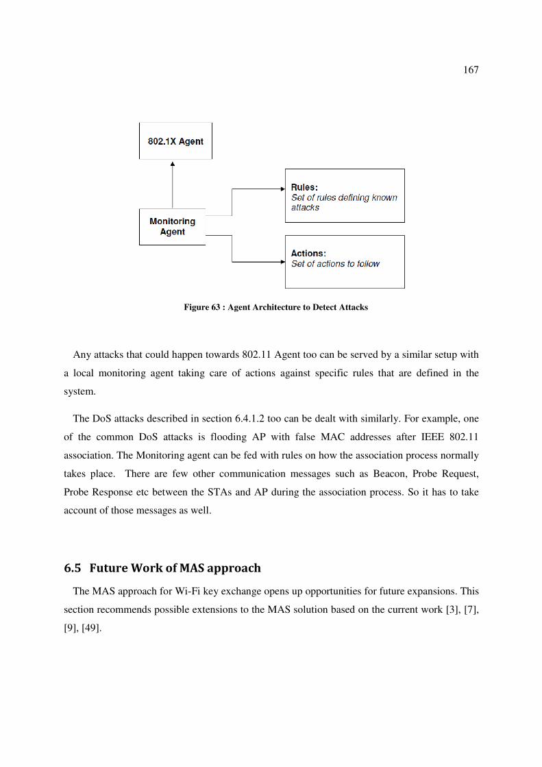
167
Figure 63 : Agent Architecture to Detect Attacks
Any attacks that could happen towards 802.11 Agent too can be served by a similar setup with
a local monitoring agent taking care of actions against specific rules that are defined in the
system.
The DoS attacks described in section 6.4.1.2 too can be dealt with similarly. For example, one
of the common DoS attacks is flooding AP with false MAC addresses after IEEE 802.11
association. The Monitoring agent can be fed with rules on how the association process normally
takes place. There are few other communication messages such as Beacon, Probe Request,
Probe Response etc between the STAs and AP during the association process. So it has to take
account of those messages as well.
6.5 Future Work of MAS approach
The MAS approach for Wi-Fi key exchange opens up opportunities for future expansions. This
section recommends possible extensions to the MAS solution based on the current work [3], [7],
[9], [49].

168
6.5.1 Implement the Intelligence to detect attacks
Wi-Fi networks comprise several IEEE protocols like 802.11, 802.1X, EAP etc. Due to the fact
that the communication medium is open air, the message flows of these protocols are subject to
various adversary attacks. Implementing a Monitoring agent as described in section 6.4 is the
best way to detect and prevent attacks.
6.5.2 Extending to Support Multiple EAP types
In this approach only the one EAP type has been considered during 802.1X authentication.
This is mainly to simplify the work to facilitate multi agent implementation. There are many
other EAP types such as EAP-MD5, EAP-TLS, EAP-TTLS, LEAP, EAP-IKEv2, EAP-SIM,
EAP-AKA available as of now. This solution can easily be extended to support all these EAP
types. This can be achieved by having respective EAP Agents implemented under 802.1X Agent.
This agent oversees all the EAP types defined in the system. Figure 64 shows the architecture of
multiple EAP types.
Figure 64 : The extended architecture to support multiple EAP types
Thus new EAP types can be added to the system with ease via a separate agent. The respective
agent holds all implementational details pertaining to a specific EAP type. This way,
modifications to any of those EAP types can be done with minimal impact to other operations.

169
6.5.3 Extending to Support Multiple QKD Protocols
Multiple QKD protocols too could be supported in a similar way as the solution is extended to
support different EAP types. For this MAS model, SARG04 has been used as the QKD protocol.
In reality, a few other widely used QKD protocols exist with a high possibility of many more
may be introduced in future. Hence the solution should be flexible enough to support those QKD
protocols as well.
As the solution, a new agent called QKD Agent is introduced into the enterprise. This agent
acts as the main controller of the QKD protocols supported by the system. All QKD protocols
are defined under the QKD Agent. All other QKD agents can define under the control of this
QKD Agent as shown in Figure 65.
Figure 65 : Extended architecture to support multiple QKD Protocols
The modified enterprise with the expansions proposed in sections 6.5.2 and 6.5.3 are shown in
Figure 66. Based on the agreed QKD protocol during the association, QKD Agent first sets up
the quantum channel to distribute the key. It informs the hardware apparatus about the specific
parameters such as number of bases to be used, synchronization information etc, that depend on
the type of QKD protocol chosen. Once the quantum transmission ends, QKD agent calls the
respective QKD type agent such as SARG04 to proceed with the key extraction. The rest of the
process then continues with four QKD agents to recover the key. This process is unchanged.

170
Figure 66 : Modified Enterprise supporting multiple QKD protocols and EAP types
In this approach, the Coordination Agent keeps a record of what type of QKD protocols the
enterprise is capable of supporting. So that, during the association it can negotiate what QKD
protocols STA wants. Alternatively the QKD Agent can keep all these QKD protocol
information leaving Coordination Agent to enquire from it when needed. However the former is
the better approach as if IEEE 802.1X authentication fails, there is no need for a QKD Agent.
6.5.4 Use of Mobile Agents for Wider Coverage
Another important feature that this MAS solution can offer is its ability to use mobile agents to
facilitate handovers for wireless devices. The Co-ordination Agent keeps a copy of all relevant

171
information of a STA with respect to its connection with the AP. This would contain the
particulars of the association as well as QKD information such as QKD protocol, reconciliation
protocol etc. Most importantly it contains the secret key that has been established to encrypt the
data.
Whenever a STA requires a handover due to weak coverage, the AP which is part of a cluster
AP, normally decides the best possible neighbour cell for handover depending on the information
of the established session. AP can then push these particulars to the new AP via a mobile agent.
Once handed over to the new AP, the same session can continue without any interruptions
achieving seamless communication. This mechanism again saves communication cycles that
otherwise would have been needed to do a fresh association [49].
In fact it is not mandatory for a mobile agent to carry QKD specific information such as QKD
and reconciliation protocols being used. However these particulars are very useful if the
communication is broken for some reason with the new AP. In such instances, new QKD can be
attempted without negotiating the same particulars since they have all the relevant QKD
information carried over by the mobile agent.
Although Wi-Fi networks mostly consist of isolated hotspots, this solution is possible with
WiMax networks. WiMax is built on IEEE 802.16 standard where the coverage area is much
wider than Wi-Fi. Since the key distribution is applicable to WiMax also, the MAS solution can
be extended to support both these well established networks to offer much wider coverage.
6.5.5 Communication between agents
Since the idea of using MAS came out as a future enhancement to this project, not all the
implementation is completed at present. The main pending work is to implement the
communication between agents. Most of the present MAS tools including JADE [80] only
support Java as the programming language. Since the current research is built on C++, analysis
has been done to develop a new prototype for communication between agents. Appleby and
Steward of BT Labs have used a similar approach to prototype a mobile agent based system for
controlling telecommunication networks [84]. The only reason to develop such prototype based
on C++ for agent communication is to reuse the code that has been already written in the same

172
language. However, this option is not necessarily required if a fresh approach is attempted on
this path. The same implementation can be done using Java and use the existing tool such as
JADE for agent communications.
Figure 67 shows an example of how the agents can interact with a Knowledge Query
Manipulation Language (KQML) [82] declarative communication language. It shows only the
first 2 messages of 802.11 association, as an example.
Figure 67 : An example of KQML block for communication
The Agent UML diagram representing the whole QKD protocol handled by SARG04 Agent is
show in Figure 68.

173
Figure 68 : Agent UML interactions of QKD

174
6.6 Summary of MAS Approach
This chapter discussed a novel concept of using Multi Agents in QKD based key distribution
protocol in Wi-Fi networks. It has been shown that the main protocol flow of this protocol can be
broken down to several sub-modules. Each sub-module can be represented by an agent, where
those agents work together to achieve a common goal of distributing the key. In doing so, a new
enterprise and an agent society have been formed. This agent society is particularly useful at AP
side since it plays a key role within Wi-Fi networks. As the AP assigns a separate enterprise to
look after each STA, the work load can be distributed. This is one of the key requirements for
Multi Agent Systems.
The use of Multi Agent Systems for this quantum based key distribution in IEEE 802.11i
networks offers several advantages.
The whole protocol can be subdivided into smaller modules to work independently. These sub-
modules can be represented by individual agents to accomplish the main task. In this way the
workload is distributed among the sub-modules, rather than handling by a single piece of
software (centralised approach). Since the system is modularized, maintenance of the system
such as adding, modifying and deleting agents can be achieved with ease.
It also provides extensibility to the system. For an example, there are different varieties of EAP
types such as EAP-TLS, EAP-TTLS, PEAP etc in use for 802.1X authentication. Therefore,
rather than having separate communication flows for each of them, wrapper agents can be used
to implement those different EAP variants. The same approach can be applied to get services of
different QKD protocols. Similarly varieties of reconciliation protocols can also be easily added
into the system as separate agents.
The system maintenance becomes easy as the agents can work independently. Whenever a new
change is required to the protocol, it can be done with less effort, without affecting the other
agents. It also provides extensibility by allowing interconnection and interoperation of multiple
existing legacy systems (for example WEP based systems) by adding them as individual agents
into the agent society.

175
Agents also bring the intelligent behaviour into the system. This is a special feature where
other wireless networks are lacking. With this feature, the agents can be taught to detect possible
adversary attacks. Such attacks can be identified and take necessary precautions achieving
reliability and robustness
It can be concluded that the use of Multi Agent Systems in QKD based Wi-Fi networks offer
many benefits. There are other research works underway in the Wi-Fi area using software agents
[81].
Since this MAS approach has been done as a future enhancement to the main project, the
implementation of the full system was not possible due to time constraints.

176

177
Chapter 7 Conclusion and Future Work
Wireless networks are increasingly popular due to mobility, affordability, flexibility,
convenience and coverage etc. The International Telecommunication Union (ITU) statistics
reveal rapid ICT growth in many world regions in everything from mobile cellular subscriptions
to fixed and mobile broadband, and from TV to computer penetration - with mobile technology
acting as a key driver [40]. Out of many wireless technologies, IEEE 802.11 networks,
commercially known as Wi-Fi has attracted millions of users worldwide.
However, risks are inherent in wireless technology. The most significant source of risks in
wireless networks is that the technology’s underlying communication medium, the airwave, is
open to intruders. Due to this reason many efforts have been put into address security issues in
wireless networks. As the number of public Wi-Fi hot spots has grown dramatically over the last
few years [41], providing secure communications to the users becomes a great concern. This
research has been aimed at finding an improved way of providing security to the Wi-Fi
communications.
Quantum cryptography is a promising field with respect to the applications of the method and
the method itself is interesting through combining several directions within natural science. If the
presumption implied in this method could learn to utilize with total confidentiality, this technique
could be of great interest to the public as well as to the telecommunication operators. For this
research, quantum key distribution has been considered as the solution to provide increased
security to the existing 802.11 networks. The advantage of quantum cryptography over
traditional key exchange methods is that the exchange of information has been shown to be
secure in a very strong sense, without making assumptions about the intractability of certain
mathematical problems. Based on the laws of physics, QKD offers unconditional security with
the way the key distribution is done. For wireless networks such as IEEE 802.11, quantum
cryptography can offer better results in providing secure data communications.
Since the aim is to establish the 802.11 key hierarchy in a secure manner, the existing key
distribution process known as 4-way handshake has been replaced with the 4-phase handshake of

178
QKD. The process of QKD takes place in two stages involving the quantum channel and the
classical channel.
This research mainly focused on the software development of the classical channel, in this case
the 802.11 wireless channel. The main aim was to implement a prototype by modifying the
existing 802.11 protocol that would use QKD to distribute key. Doing so, careful analysis was
done to identify how to implement QKD without impacting the existing 802.11 frame structure.
QKD involves some key parameters relevant to both quantum transmission and the QKD
protocol itself. These parameters include quantum transmission rate, type of QKD protocol, type
of reconciliation protocol, hash function to be used etc. Thus it is essential for AP and STA to
agree to a specific set of parameters to be used during the protocol execution at the beginning of
the association. As the solution, the existing beacon, probe request and probe response messages
have been used to agree upon those parameters. Thus at the very beginning of the
communication, AP and STA tell each other if they support quantum transmission. If so, they
can then negotiate the QKD and reconciliation protocols and other parameters to be used for the
rest of the communication. In doing so, the existing beacon, probe request and probe response
frame structure has been used without any changes. The only modifications have been done to
some of the field parameters of the existing frames. These fields have been carefully chosen from
the existing frames that have been used for 4-way handshake. In addition, few of the unused
fields have also been used.
Once the 802.11 association is done, to implement the 4-phase handshake protocol, the
existing EAPOL communication frames have been used. New information elements (IEs) have
been introduced to carry the QKD specific traffic. Since information elements are already
supported by the existing EAPOL standard, the overall process does not require additional
resources. By using the existing frames to implement the QKD protocol, the overall 802.11
protocol frame structure has not been impacted. With this approach, the classical channel only
requires software updates that are needed to support the QKD protocol. Thus the classical
channel of the proposed solution can easily be implemented using the existing 802.11 protocol.
When compared to the existing protocol, it could be seen that only the reconciliation process
taking few additional EAPOL flows. However, the key exchanged in the existing protocol needs
to be refreshed at regular intervals or upon requested by STA [55] to maintain security of data

179
encryption. But in the proposed QKD based Wi-Fi protocol, such key refresh cycles are not
needed as the key exchanged provide unconditional security. Hence with this new protocol a
significant amount of processing time could be saved. Overall, this can compensate for the extra
cycles of flows taken during the reconciliation process.
In case, if any participating agent (AP or STA) does not support QKD or does not require
unconditional security offered by the QKD, they can still proceed with the normal 802.11
procedure. This provides better options for both APs and STAs. This is one of the main
advantages of the proposed protocol as it has been designed to work with the existing 802.11
protocol.
The main advantage of this proposed protocol is its ability to offer unconditional security to
the users. As the wireless hot spots across the world grow day by day, so does the number of
users seeking their services. This invariably increases the potential security threats. As per
current trend of communication technology, many users depend on the wireless networks for
their essential day-today activities. These activities include essential business, defence,
educational, leisure etc. Out of those, there are some critical activities such as business, defence
etc that require extra security when using the wireless networks. Such users, and others, can gain
the maximum advantage by relying on the proposed QKD based Wi-Fi solution for their
communications. This approach will further boost the usage of 802.11 networks amongst clients
as they can use the service with much confidence.
Considering the overall solution, simulation results have shown that the proposed QKD
approach also offers results within acceptable limits. During the simulations, parity based bisect
algorithm has been chosen as the reconciliation protocol. In comparison to other reconciliation
protocols, the parity check method involves significant amount of processing cycles. The reason
to choose this particular method is to observe the behaviour under the worst possible conditions.
The results prove that even under such extreme situations, the overall QKD protocol shows much
improved performances.
Apart from the reconciliation phase, the other three phases are common to general QKD
protocols. Hence the analysis has been done in such a way so that performances of each phase
can be done separately. Software developments have also been done to support this

180
methodology. As per the simulation results performances of sifting, error estimation and privacy
amplification phase under various conditions are pretty much similar.
Research work carried out at the University of Canberra has demonstrated QKD systems of
distances vary between 4.2 km to 30 km in free space. The results obtained have varied QBER
values experimented against various atmospheric conditions. However, Wi-Fi networks only
cover a maximum distance of 200m. Hence the amount of atmospheric disturbances is much less
for Wi-Fi networks. The quantum channel data of this QKD system has been used for the
proposed QKD based Wi-Fi project. Since this research is focused on the wireless channel (as
the classical channel), there is no impact of using those quantum channel data as the input. The
simulation set up has been designed in such a way that it can take many variations of quantum
channel outputs. Lower bound of 20% and upper bound of 40% for error rates have been
carefully selected so that the simulations are able to predict the behaviour of the system quite
effectively.
Since there are no Wi-Fi devices that are equipped with quantum transmission facilities
available as of now, this research relied on the devices used in the university QKD test bed. As
the quantum channel and classical channel of QKD are independent, this does not have any
impact on the outcome of this project. Considering the quantum communication enabled mobile
apparatus, there are some research activities progressing in this path. For example a system
involving QKD to transfer ATM PIN numbers using cell phones has been in development at the
HP labs [44]. Thus the technology is not far behind from making the quantum embedded mobile
devices a reality.
Quantum cryptography promises to revolutionize secure communication by providing security
based on the fundamental laws of physics, instead of using the current state of mathematical
algorithms or computing technology. The devices for implementing such methods exist and the
performance of demonstration systems is being continuously improved. The choice of QKD in
Wi-Fi networks to distribute the secret key is advantageous in many ways. The proposed
protocol is not specifically targeted to improve the efficiency, but to improve the security by
using QKD to distribute the secret key.
Another advantage of this proposed protocol is allowing flexibility to users to choose the level
of security required. The proposed modifications are done in such a way that at the very

181
beginning of the communication, both parties can negotiate if they support QKD or not. If any
party does not support or not require additional security offered by QKD, they can still move on
with the existing protocol. The proposed QKD based Wi-Fi protocol can be extended to WiMax
and to support IEEE 802.21. IEEE 802.21 is developing standards to enable handover and
interoperability between heterogeneous network types including both 802 and non 802 networks
[12]. This standard aims to enable seamless handover between networks of the same type as well
as handover between different network types. With regard to the proposed QKD solution, not all
AP are required to equip with quantum transmission. This is because, if the very first connection
to the AP network is done via an AP that support quantum transmissions, then the secure key has
been obtained via the QKD. Thus, whenever a handover takes place, this key can be transferred
from old AP to the new AP. This transfer is secure as the AP side network is wired and consists
of authorized APs only. Hence the new AP is not required to have equipped with quantum
transmission facilities as the secured key is already obtained from the old AP.
The next few sections describe the possible enhancements to the proposed QKD based Wi-Fi
protocol. Several approaches have been discussed to improve the proposed solution to become
more flexible, robust and mobile.
7.1 Use of One Key for Multiple Sessions
Another advantage of this solution is since the secret key generated via QKD is
unconditionally secure, the same key can be kept for future communications if required. This is
quite possible if the two parties, AP and STA can keep their secret keys in a safe manner
something similar to pre-shared key scenario of 802.11 standard [8]. The copy of the key holding
with AP can be assumed to be safe as the AP belongs to a trusted network. This is very similar to
a bank keeping PIN information of its customers, where both parties keep the copies of the key
securely. With this kind of an approach, future communication between the same AP and STA
does not need to go through 4-phase handshake process, saving time and resources.
Further, this concept can be expanded for AP’s side to have a central database to hold the
secret key transferred during the very first association. Once the key is exchanged, the central
database can be updated with the key. During future attempts by the same STA to gain access to

182
Wi-Fi network, not necessarily the same AP, STA can be authenticated successfully since AP’s
network has a copy of the key. To achieve this, APs should form a network to share a central
database. This scenario is illustrated in Figure 69.
For more flexibility, during the very first QKD session, STAs can be asked to exchange a very
long key. Then part of those key bits can be used to authenticate the STA each time trying to
gain access to the network. This approach is safe as they have a shared secret (part of the key)
before the communication begins. After a successful association to the network, key bits that
used can be removed from the main key. Thus each time STA access the network, a fresh key
obtained from the main key is used making the key unique all the time. Once all the bits of the
main key are used, they can initiate a fresh QKD session to establish a new key. Further, if any
suspicious or fraudulent action is observed, APs can force the STA to initiate a fresh QKD
session.
This solution can also be extended to support the emerging IEEE 802.21 standard on handover
between heterogeneous wireless networks.
Figure 69 : Scenario of One Quantum Key for Multiple Sessions
183
7.2 Multi Agent Solution
The multi agent system discussed in Chapter 6 is also proposed as a future expansion. A
significant amount of design work has been done on the MAS option. Necessary infrastructure
for MAS networks is well established and networks involving agents are active nowadays. Hence
the MAS solution for wireless technology is a good idea to explore.
It has been shown that the main protocol of the proposed protocol can be broken into several
sub-modules. Each sub-module can be represented by an agent, where those agents work
together to achieve a common goal of distributing the key. This agent society is particularly
useful at AP side as it plays a key role within Wi-Fi networks. As the AP assigns a separate
enterprise to look after each STA, the work load can be distributed. This is one of the key
requirements for Multi Agent Systems.
This agent approach provides many advantages to the wireless communication. Since the key
work flows are incorporated into agents, maintenance too becomes easy. Whenever a new
change to the protocol is needed, it can be done with less effort, without affecting the other
agents. It also provides extensibility by allowing different EAP wrapper agents to facilitate
different EAP types. This is very useful as different STAs support different types of EAP
methods. It also provides extensibility by allowing interconnection and interoperation of multiple
existing legacy systems (for example WEP based systems) by adding them using a wrapper into
the agent society.
With the MAS solution, the handovers of Wi-Fi devices between access points can be achieved
by using mobile agents. It was further shown how the secret key too can be moved or shared
between networks saving time and resources. With this kind of approach, not all access points in
a network need to be equipped with quantum transmission apparatus. The secret key distribution
can be done using an AP that support quantum transmission, while for the rest of the
communication can be supported by any ordinary AP. Most importantly, it was shown that the
MAS solution can potentially be extended to support interoperability between different types of
networks such as IEEE 802.11, IEEE 802.16 etc. The MAS solution should also be possible to
extend to support the IEEE 802.21 developing standard.

184
7.3 Overcoming Line-of-Sight Issues
The main issue of quantum transmission with QKD systems is the requirement of line-of-sight
between the transmitter and the receiver. Wi-Fi networks are mostly established in the form of
hotspots covering smaller areas. Most typical examples of hotspots are coffee shops, air ports,
libraries, universities etc. Long distance free space quantum transmissions are mostly impacted
by line-of-sight issues with obstacles such as buildings, tress, and geographical conditions.
However for Wi-Fi networks the impacts due to such conditions are very negligible. Further, in
normal QKD systems transfer key bits are very long, mostly in the form of megabits. But for Wi-
Fi, the secret key, required is very small. Hence it only takes a very small time for quantum
channel to transmit the key bits. Thus the alignment between the photon transmitter and receiver
only needs to be in line-of-sight for a very short time only. This kind of transmissions is quite
possible with Wi-Fi networks due to the limited coverage and nature of network technology.
7.3.1 Use of MIMO Technology
However, it is worthwhile to look for other possible technologies that could provide remedies
to the line-of-sight issue. One such technology that could offer a solution is the use of Multiple-
Input Multiple-Output (MIMO) technology for quantum communication. MIMO refers to the
ability of equipment to handle multiple data input and multiple data output operation. Recent
advancements on MIMO technology for quantum transmissions [42], [43], [46], [51] show
alternate ways towards eliminating the LOS restriction. Wi-Fi certified devices make use of
multiple antennas to send and receive more than one communication signal simultaneously. This
is similar to having two FM radios tuned to the same channel at the same time - the signal
becomes louder and clearer. This multiplies the performance of the Wi-Fi signal, and is reflected
in the two, three, or even more antennas found on some Wi-Fi certified access points or routers.
By using MIMO technology, the quantum transmission can be done using multiple transmitters
and receivers. Once the quantum transmission is started, if they lose the line-of-sight for some
reason, the quantum channel can continue with the next best transmitter or receiver pair which
has the best line-of-sight. For this kind of architecture, quantum apparatus should form a mini
network allowing internal connections to identify the line-of-sight issues. It must be noted again

185
that the time required for quantum transmission is very small and there is little probability that
the line-of-sight issue might occur in Wi-Fi networks.
7.3.2 Use of Cognitive Radio Communications
Cognitive Radio (CR) is the next disruptive radio communication and networking technology.
It is currently experiencing rapid growth due to its potential to solve many of the problems
affecting wireless communications. A cognitive radio is a radio that can change its transmitter
parameters based on interaction with the environment in which it operates [131]. It is a paradigm
for wireless communication in which either a network or a wireless node changes its
transmission or reception parameters to communicate efficiently avoiding interference with
users. The majority of cognitive radios will probably be SDR (Software Defined Radio) but
neither having software nor being field programmable are requirements of a cognitive radio.
The cognitive radio concept is based on two main characteristics: reconfigurability and
intelligent adaptive behaviour. The intelligent adaptive behaviour is the ability to adapt without
being a priori programmed to perform a specific task via some form of learning. For example, a
handset that learns a radio frequency map in its surrounding could create a location-indexed
RSSI (Received Signal Strength Indicator) vector (latitude, longitude, time RF, RSSI) and uses a
machine-learning algorithm to switch its frequency band as the user moves.
Cognitive radio requires several key functionalities:
• Flexibility and agility: the ability to change the waveform and other radio operational
parameters on the fly.
• Sensing: the ability to observe and measure the state of the environment.
• Learning and adaptability: the ability to analyse sensory input, to recognize patterns
and modify internal operational behaviour.
Research work using CR on Wi-Fi networks is also under way. Techniques are proposed to use
CR to optimise AP transmission power and channel allocation within Wi-Fi networks [132] and

186
intelligent load balancing techniques to optimize the overall Wi-Fi network performance [134].
Use of CR to fix the line-of-sight issues on quantum transmission is worth looking.
A similar approach to that proposed in section 7.3.1 for MIMO, can be used with CR to
achieve seamless quantum transmission. CR can be used to make intelligent decisions for
handovers between different photon transmitters/receivers when the line-of-sight is not possible.
7.3.3 Other Solutions for Line-of-Sight
Several other possible solutions have been proposed for the line-of-sight issue. One such
proposal is the optical tracking technique. The optical pointing, acquisition and tracking
techniques developed for laser communications could be used to make QKD possible over line-
of- sight transmission in free-space [116], [119], [120].
As a sub-division to this project, the use of fuzzy dynamic switching option is also considered
as a possible solution to the line-of-sight issue [14]. In this research, a two dimensional fuzzy
dynamic switching for quantum channel has been proposed.
In another proposal, an architecture consisting of automated alignment protocol is suggested
[35], [118]. The control protocol is able to detect and position the mobile apparatus in line with
the photon transiting network of AP. If an obstacle is detected during the use of quantum
channel, the system gives instructions to the mobile device to use another available fixed
apparatus.
The use of indoor wireless optical channels is also worth investigating to resolve LOS issues.
This technology allows multipath dispersion in indoor optical communication. It does not rely
upon the LOS path, instead relies on reflections from a diffusive reflectors [162].
7.4 Use of Virtual Private Network in Wi-Fi Networks
In section 2.7 it was discussed that VPN solution for Wi-Fi networks was not a good option.
Even with the existing Wi-Fi networks, the key distribution is subject to various attacks such as
DoS attacks.

187
Use of QKD based Wi-Fi system overcomes these issues. The QKD approach improves the
security aspect of the overall data communication. Hence it is much better than the VPN and
traditional Wi-Fi protocol with respect to key distribution [48].
The QKD approach for Wi-Fi offers unconditional security to the overall communication. This
solution raises the security of wireless networks to a new height where it is not possible to break
the key exchanged via QKD. Hence this QKD based approach is far superior to the VPN solution
in Wi-Fi communications.
Most importantly the use of VPN is still possible with the QKD based Wi-Fi solution. This is
because the VPN process takes place after the secure key is exchanged using QKD. Hence the
existing use of VPN in Wi-Fi networks is not impacted by the QKD based solution.
At the same time QKD based Wi-Fi protocol has no impact on the use of VPN over Wi-Fi.
This solution still allows clients to use VPN if required and act as a hybrid VPN.
Further, research work of using QKD approach for VPN has been done as a project by a team
from BBN Technologies, Boston University and Harvard University [101]. In this work, they
plan to design and build the world’s first highly secure quantum network, one that delivers end-
to-end network security via high-speed QKD. This quantum network has been designed to
distribute keys for a virtual private network (VPN) overlay running atop an underlying public or
private internet.
7.5 Extending QKD for WiMAX
Worldwide Interoperability for Microwave Access (WiMAX) is the emerging broadband
wireless technology based on IEE 802.16 standards [50], [85]. With the increasing popularity of
broadband internet, the wireless networking market is thriving. WiMAX can be used for wireless
networking in much the same way as the more common Wi-Fi protocol.
WiMAX is a second-generation protocol that allows for more efficient bandwidth use,
interference avoidance, and is intended to allow higher data rates over longer distances. WiMAX
is intended for the licensed spectrum in which contention among providers with different
interests is eliminated.

188
Analysis shows that the QKD based solution used in Wi-Fi can be extended to distribute keys
in WiMAX (IEEE 802.16) as well.
7.5.1 WiMAX Security
The security architecture of IEEE 802.16e [85] comprises two component protocols:
• An encapsulation protocol to secure packet data. This protocol defines a set of
supported cryptographic suites, i.e. pairing of data encryption and authentication
algorithms and the rules for applying those algorithms.
• A key management protocol (Privacy Key Management - PKM) providing secure
distribution of keying data from the Base Station (BS) to the Subscriber Station (SS).
Through this management protocol, SS and BS synchronise keying data [85].
The PKM protocol allows both mutual authentication and unilateral authentication. It also
supports periodic re-authentication/re-authorisation and key refresh. It uses either EAP or X.509
digital certificates together with RSA public key encryption algorithm or a sequence starting
with RSA authentication and followed by EAP authentication.
During the PKM authorisation via RSA authentication protocol, an SS begins authorisation by
sending an Authentication Information message to its BS. This message contains the X.509
certificate of SS’s manufacturer, issued by either manufacturer itself or by an external authority.
This Authentication Information message is strictly informative, thus BS may choose to ignore it.
However it provides a mechanism for a BS to learn the manufacturer certificates of its SSs.
Immediately after the Authentication Information message, SS sends Authorisation Request
message. This request is for an Authorisation Key (AK), as well as for the Security Association
IDs (SAID) identifying any Static Security SAs the SS is authorised to participate in. The
Authorisation Request includes manufacturer issued X.509 certificate [88], a description of
cryptographic algorithms and the SS’s Basic Connection Identifier (CID).
In response to Authorisation Request message, BS validates the SS’s identity, determines the
encryption algorithm and protocol support it shares with the SS. During this process, BS verifies

189
SS’s identity via X.509 digital certificate, if it is authorised for basic unicast services and what
additional statically provisioned services the SS has subscribed for. BS then activates an AK for
SS, encrypts it with the SS’s public key and sends Authorisation Reply message. This
Authorisation Reply message also includes, a 4-bit key sequence number used to distinguish
between successive generation of AKs, a key life time and identities and properties of static SAs
the SS is authorised.
In this way PKM’s authentication protocol establishes a shared secret, AK, between SS and
BS. This shared key is then used to secure subsequent PKM exchanges of Traffic Encryption
Keys (TEK).
An SS shall periodically refresh its AK by reissuing an Authorisation Request to the BS.
Reauthorisation is identical to authorisation with the exception that the SS does not send
Authentication Information messages during the reauthorisation cycles.
To avoid service interruptions during reauthorisation, successive generation of the SS’s AKs
have overlapping lifetimes. Both SS and BS should be able to support up to two simultaneous
active keys during these transition periods. This process of managing AK is shown in Figure 70.

190
Figure 70 : AK Management in BS and SS [85]
Upon authorisation, SS starts a separate TEK state machine for each SAID identified in
Authentication Reply message. TEK is encrypted using appropriate Key Encryption Key (KEK)
derived from AK.

191
BS maintains two sets of active TEK per SAID, where their lifetimes overlap. BS uses the
older of two active TEKs to encrypt downlink and the other to decrypt uplink traffic. The TEK
management in BS and SS is shown in Figure 71.
Figure 71 : TEK management in BS and SS [85]
The Key Encryption Key (KEK) is derived directly from AK. It is used to encrypt the TEKs,
Group Key Encryption Key (GKEK) and all other keys sent by the BS to SS in unicast message.

192
The GKEK is randomly generated at the BS and transmitted to the SS encrypted with the
KEK. GKEK is used to encrypt the GTEKs sent in a multicast message by the BS to the SS in
the same multicast group.
The Traffic Encryption Key (TEK) is the key used for encrypting user traffic. TEK is
generated as a random number in the BS and is encrypted using the corresponding TEK
encryption algorithm, keyed with the KEK and transferred between BS and SS in the TEK
exchange. SS decrypts it by KEK it has. TEK is periodically regenerated by BS on request from
SS where SS makes this request on TEK life time expires. SS may have multiple SAs. Each SA
has its own TEK.
The Group Traffic Encryption Key (GTEK) is used to encrypt multicast data packets and it is
shared among all SSs that belong to the multicast group.
7.5.2 Security issues with WiMAX
Though WiMAX is widely popular, it was found to have some weaknesses on typical attacks
on authentication [25], [54], [3]. One of the most common type of attack was Message replay
attacks or Denial of Service attacks. The protocol identifies each TEK with 2-bit sequence
number, wrapping the number from 3 to 0 on every 4th
key. If a reply attack is successful, TEK
and subscriber data will be at a risk. In addition, it was found to be open to Man-In-The-Middle
attacks as well.
During AS generation, BS contributes to all the bits. SS must trust that BS always generates
fresh AK, cryptographically separated from other AKs. Hence BS’s random generator must be
perfect.
Downgrade attacks are also possible with WiMAX. The first message of the authorisation
process is an unsecured message from SS telling BS what security capabilities it supports. An
attacker could send a spoofed message to BS containing weaker capabilities in order to convince
BS and SS to agree on an insecure encryption algorithm. This renders the rest of the
communication vulnerable to attackers.

193
7.5.3 Use of QKD for Key Distribution in WiMAX
It could be seen that a 160 bit long AK plays a major role in WiMAX key hierarchy, similar to
the PMK in Wi-Fi. All the non-traffic and management message data are encrypted directly by
AK or by some key that is derived from AK. AK is given to SS after it has been authorized.
Several other keys such as KEK, MAK (Message Authentication Key), H-MAK (Hashed MAK),
H-MAK Digest are derived from AK. AK is periodically regenerated by BS on request from SS
(SS makes this request on AK lifetime timer expires).
The QKD approach can be extended in WiMAX to distribute this AK. This process will make
AK unconditionally secure, thus resulting in other keys such as KEK, TEK being also secure.
QKD could be introduced into the communication soon after the X.509 certificate is exchanged.
At this stage both parties can switch to the quantum channel to start the photon transmission.
Once completed, they can switch back to wireless channel to recover the key by implementing
the four stages of 4-phase handshake. Upon the completion of both BS and SS will have identical
secured key (Q-key). At this stage, BS will encrypt the public key received from the SS with the
Q-key and send across to SS. SS in turn validates the key by decrypting using the Q-key,
ensuring the message integrity.
This QKD approach for WiMAX key distribution offers many benefits to the overall
communication, the first being the unconditional security gained thorough the quantum
cryptography. As the key obtained offers unconditional security, the rest of the data
communication becomes safe and impossible to break.
This solution also eliminates the use of key fresh cycles. At present, AK and TEK have their
own life times within the communication. With the QKD solution, the key is secure and there is
no need for key fresh cycles. In this way, a lot of communication flows used for key
refreshments could be saved. Hence the overall efficiency of the protocol could be vastly
improved.
Since WiMAX networks also support handovers, the secured key of BS can be easily and
securely transferred between BSs of the network to make the communication possible across the
whole network.

194
7.6 Universal Architecture for Key Distribution in Wireless Networks
The key distribution of IEEE 802.11 standard takes a single master key and splits it into the
several keys to establish the key hierarchy. By using this key derivation, stations can refresh
encryption keys without re-running the whole authentication process [45]. The PMK is the root
secret that must be carefully protected because all keying material is derived from it. The IEEE
802.16 standard also relies on Privacy Key Management (PKM) to build up the key hierarchy.
It could be seen that all wireless networks have something in common: establish a secure key
(or key hierarchy) at the beginning of the communication process. The key derivation normally
happens once the authentication is completed. Thus it is worth exploring to find out how this
feature of key derivation can be achieved as a common deployment across all wireless networks.
Different wireless standards define different strategies to establish the key hierarchy. QKD can
be chosen as the common method to distribute the key. The quantum channel of QKD takes
place independently of the classical channel. Hence the universal approach should focus on the
classical (wireless) channel. This is possible to achieve by having a common protocol to
implement the functionalities of the classical channel. Since the sifting, error estimation and
privacy amplification are common across all QKD protocols, developing a common protocol to
implement the 4-phase handshake becomes less complex. These three phases do not involve
many communication flows. The reconciliation phase is the only one having variations due to the
fact that it has different types of reconciliation protocols to support.
As the solution, some protocol similar to the EAP can be proposed. Like EAP, several
variations such as EAP-PEAP, EAP-TLS, EAP-MD5 etc, different QKD and reconciliation
protocols can be represented by similar variations. In order to communicate these protocols over
different wireless standards, a protocol similar to EAPOL can be used. The aim of such protocol
is to provide encapsulation of QKD variants in respective wireless standards.
Since the amount of communication flows of QKD is limited, this kind of approach could
provide a universal mechanism to implement QKD in wireless standards.
Another possible enhancement to the proposed QKD protocol is the use of secret key for future
communications. This is very similar to the proposed solution discussed in section 7.1. This

195
enhancement can be extended along with the simulated protocol and does not require the above
explained universal approach.
The two approaches can be combined to offer security, flexibility and mobility to the existing
wireless networks. If the secret key distributed via QKD can be shared in a central or distributed
database, different types of wireless networks can access the database to validate the secret key.
Generally the QKD is capable of generating secret keys of very large lengths. Hence it is
advantageous to have a long key established during the initial access to the network. Each time
the user makes subsequent access to a network, part of the bits of the main key can be discarded.
This in fact can happen without any user intervention by the protocol itself. With this approach, a
new key (taken from the main key) will be used for each access to a network. A similar approach
is currently being researched for ATMs [44].
Since all different types of networks share a central or distributed database, mobility can also be
improved. Handovers between the same or different type of networks are possible since the key
information is shared.
This whole concept can be further extended to develop a standard somewhat similar to the
OpenID [155]. OpenID defines an open standard that describes how users can be authenticated in
a decentralized manner, obviating the need for services to provide their own ad hoc systems and
allowing users to consolidate their digital identities [156]. By having a secured long key
established at the initial quantum transmission, the key could be reused across different types of
applications, not just limited to wireless networks.
7.7 Achievements and Contributions against research questions
The main goal of this research work is to improve the security aspect of Wi-Fi networks. The
other key requirements were how to implement the proposed solution with minimal impact to the
existing IEEE 802.11 protocol. It was also required that the proposed solution be flexible enough
to extend for further improvements. Since Wi-Fi networks are widely used by millions of users
worldwide, there are many users who use this service to communicate extremely sensitive
information. Hence the need for providing maximum possible security is very important.
The key distribution of Wi-Fi networks is very critical in the security of the communication.
This is because, it is the key distributed between the two communicating parties used to encrypt

196
the subsequent data of the communication. The present IEEE 802.11 standard uses 4-way
handshake to distribute the secret key. However, it was revealed that 4-way handshake has some
vulnerability to security attacks.
After thorough analysis, it was found that the use of QKD to distribute the key raises the
security to new heights. Since the key distributed via QKD is proven to be unconditionally
secure, the same level of security has been extended into Wi-Fi networks. The key used to
distribute via QKD is the PTK of the existing IEEE 802.11 standard. This key is used to extract
the rest of the key hierarchy. Hence by having "unconditionally secure" PTK distribute via QKD,
the whole key hierarchy also inherit the same level of security.
With these proposed modifications, this research has achieved the main aim of improving the
security of Wi-Fi networks to the highest level with the use of quantum cryptography. With the
proposed method, QKD is implemented to distribute the secrete key by keeping the existing
EAPOL frame structure intact. Also, most importantly, the modifications are done is such a way
that use of QKD is optional for participating clients. Thus the impact on the existing protocol is
kept to a minimum.
From the efficiency point of view also the proposed protocol has achieved results within
reasonable limits. The results obtained in chapter 5 show that overall time taken for QKD based
Wi-Fi protocol does not take additional time to complete the key distribution. Also since the key
obtained in this method is unconditionally secure, it results in saving additional time needed for
key fresh cycles in the existing protocol. Further, it was shown in chapters 6 and 7 that this
proposed protocol is flexible for a number of enhancements.
Thus it can be concluded that this research has achieved all the goals that it aimed to achieve.
It is intended to continue this research work to make the proposed protocol a reality. There were
4 patents (Appendices B) and 16 research papers have been published (Appendices A) to support
this thesis.

197
Bibliography
[1] ANSI/IEEE 802.11, 1999 Edition (R2003), Part 11: Wireless LAN Medium Access Control
(MAC) and Physical Layer (PHY) Specifications.
[2] IEEE 802.1X, IEEE Standard for Local and Metropolitan Area Networks, Port-Based
Network Access Control, December 2004.
[3] Shirantha Wijesekera, Xu Huang, Dharmendra Sharma, Utilization of Agents for Key
Distribution in IEEE 802.11, The 2nd International Symposium on Intelligent Decision
Technologies, KES-IDT-2010, Baltimore, USA, July 2010.
[4] The University of Canberra – Telstra Tower Quantum Crypto – Key Telecommunications
Link, Paul J Edwards, Advanced Telecommunications and Quantum Electronics Research
Centre University of Canberra, 2002.
[5] Xu Huang, Shirantha Wijesekera, and Dharmendra Sharma, “Secure communication in
802.11 networks with a novel protocol using quantum cryptography,” IEEE 4th International
Conference on Network and System Security, NSS 2010, Melbourne, Australia, . ISBN:
978-0-7695-4159-4, pp.594-599, September 1-3, 2010.
[6] Shirantha Wijesekera, Xu Huang and Dharmendra Sharma, Quantum Cryptography Based
Key Distribution in Wi-Fi Networks - Protocol Modifications in IEEE 802.11, 5th
International Conference on Software and Data Technologies (ICSOFT 2010), Athens,
Greece, July 2010.
[7] Xu Huang, Shirantha Wijesekera, and Dharmendra Sharma, “Agent-Oriented Novel
Quantum Key Distribution Protocol for the Security in Wireless Network,” Multiagent
Systems, published by In-Tec, ISBN 978-3-902613-51-6, Vienna , Austria, pp261- 276,
2009.
[8] IEEE Std 802.11i, IEEE Standard for Information Technology – Telecommunication and
information exchange between systems – Local and metropolitan area networks – Specific
requirements. Part 11: Wireless LAN Medium Access Control O(MAC) and Physical Layer

198
(PHY) specifications, Amendment 6: Medium Access Control (MAC) Security
Enhancements,2004.
[9] Shirantha Wijesekera, Xu Huang, and Dharmendra Sharma, “Multi-Agent Based Approach
for Quantum Key Distribution in WiFi Networks,” 3rd International KES Symposium on
Agents and Multi-agent Systems-Technologies and Applications, Uppsala, Sweden, KES-
AMSTA 2009, pp293-303, 2009.
[10] Shirantha Wijesekera, Xu Huang, and Dharmendra Sharma, “A Novel Protocol using
Quantum Cryptography for Secure Communication in 802.11 Networks,” IEEE International
Symposium on a World of Wireless Mobile and Multimedia Networks (WoWMoM 2009),
Kos, Greece, June 15-18, 2009.
[11] Samuel J. Lomonaco, Jr, A Quick Glance at Quantum Cryptography, University of
Marylands Baltimore County, USA, November 1998.
[12] IEEE 802.21-2008, IEEE Standard for Local and Metropolitan Area Networks: Part 21:
Media Independent Handover Services, IEEE, http://www.ieee802.org/21/, 2009.
[13] W. Diffie and M. E. Hellman, IEEE Transactions on Information Theory, IT-22, pp. 644-654
(1977).
[14] Xu Huang, Shirantha Wijesekera, and Dharmendra Sharma, “Fuzzy Dynamic Switching in
QKD of Wi-Fi Networks,” the 5th International Conference on Natural Computation and the
6th International Conference on Fuzzy Systems and Knowledge Discovery ICNC’09-
FSKD’09 Tianjing, China. 14-16 August, 2009.
[15] Record key speed set by fiber QKD system at NIST - Code for ‘Unbreakable’ Quantum
Encryption Generated at Record Speed over Fiber,
http://www.nist.gov/itl/quantum/recordkey.cfm, 2010.
[16] Xu Huang, Shirantha Wijesekera, and Dharmendra Sharma, “Novel Protocol and Its
Implementation QKD in Wi-Fi Networks,” 8th IEEE/ACIS International Conference on
Computer and Information Science (ICIS 2009), Shanghai China, June 1-3, 2009.

199
[17] Valerio Scarani, Antonio Acin, Grégoire Ribordy and Nicolas Gisin, (SARG04) Quantum
cryptography protocols robust against photon number splitting attacks, 2004.
[18] Gilles Brassard, Louis Salvail, Secret-Key Reconciliation by Public Discussion, SBN 978-3-
540-57600-6, 1994.
[19] Xu Huang, Shirantha Wijesekera, and Dharmendra Sharma, “Quantum Cryptography for
Wireless Network Communications,” ISWPC'09, IEEE International Symposium on
Wireless and Pervasive Computing, 11-13th February 2009, Melbourne, Australia, ISBN:
978-1-4244-2966-0, Security pp.1-pp5, 2009.
[20] M. Jofre, A. Gardelein, G. Anzolin, G. Molina-Terriza, J.P. Torres, M.W. Mitchell and V.
Pruneri, 100 MHz amplitude and polarization modulated optical source for free-space
quantum key distribution at 850 nm, 2010.
[21] 802.1X-2010 - Revision of 802.1X-2004.
[22] G. Ganeshkumar, P. J. Edwards, W. N. Cheung,L. O. Barbopoulos, H. Pham, and J. C.
Hazel, “The University of Canberra quantum key distribution test bed”, 12th Australian
Optical Society Conf., p.34, University of Sydney, 1999.
[23] P. J. Edwards, G. Ganeshkumar, W. N. Cheung and L.O. Barbopoulos, “Quantum
cryptographic key distribution: A 21st Century technology”, ITEE Society Monitor 25, pp.
12-15, 2000.
[24] P. Lynam, A. Blake, C. Cochran, P. J. Edwards, The University of Canberra –Telstra Tower
Free-Space Quantum Key Distribution Test-bed, ITEE Society Monitor 27, pp 26-30, March-
May 2002.
[25] Security Issues and Proposed Solutions Concerning Authentication and Authorization for
WiMAX, Bart Sikkens, March 2007.
[26] Shirantha Wijesekera, Xu Huang and Dharmendra Sharma, Quantum Cryptography Based
Key Distribution in IEEE 802.11 Networks – Analysis on Reconciliation Phase, 7th
International Wireless Communications and Mobile Computing Conference (IWCMC 2011),

200
Trust, security and privacy Symposium, Istanbul, Turkey, July 2011 (Accepted and to be
appeared).
[27] P. J. Edwards, A. Blake, J. Gleeson, C. Cochran, H. B. O’Keefffe, P. Lynam, Transmission
of quantum key bits over a 14.3 km atmospheric path, December 2003.
[28] P.J. Edwards, The Telstra Tower / University of Canberra Quantum Cryptographic
Telecommunications Link, Invited Paper (WARS02), February 2002.
[29] G. Ganeshkumar, P. J. Edwards, W. N. Cheung, L.O. Barbopoulos, H. Pham, J.C. Hazel, The
University of Canberra Quantum Key Distribution Test-bed, 12th
Australian Optical Society
Conf., p.34, University of Sydney, 1999.
[30] Xu Huang, Shirantha Wijesekera and Dharmendra Sharma, “Novel Protocol for Quantum
Cryptography of Secure in Wireless Communications” the IEEE 11th International
Conference on Advanced Communication Technology, February 15-18, Phoenix Park,
Korea. ISBN: 978-89-5519-139-4, pp 913-918, 2009.
[31] Xu Huang, Shirantha Wijesekera, and Dharmendra Sharma, “Implementation of QKD in
802.11 Networks,” IEEE 2009 International Conference on Networks Security, Wireless
Communications and Trusted Computing (NSWCTC 2009), 25-26 April 2009 in Wuhan,
Hubei, China. Proceedings Vol 2, pp.125, 2009.
[32] A. K. Ekert, Phys. Rev. Lett. 67, 661, 1991.
[33] Generalized privacy amplification., Charles H. Bennett, Gilles Brassard, Claude Crépeau,
and Ueli M. Maurer, IEEE Transactions on Information Theory, 41(6):1915-1923, November
1995.
[34] Edwin Lyle Brown, 802.1X Port-Based Authentication, Auerbach Publications, ISBN 1-
4200-4464-8, 2007.
[35] Nguyen, T.M.T., Sfaxi M. A., Ghernaouti-Helie S., 802.11i Encryption Key Distribution
Using Quantum Cryptography, Journal of Networks, Vol 1, No 5, Sep/Oct 2006.

201
[36] High Speed Quantum Key Distribution System Supports One-Time Pad Encryption of Real-
Time Video1, Alan Mink, Xiao Tang, LiJun Ma, Tassos Nakassis, Barry Hershman, Joshua
C. Bienfang, David Su, Ron Boisvert, Charles W. Clark and Carl J. Williams.
[37] New Hash Functions and Their Use in Authentication and Set Equality, Wegman, Mark. N.
and Carter, J. L. J. Comput. System Sci., Volume: 22, Issue: 3, 265-279, 1981.
[38] Xu Huang, Shirantha Wijesekera, and Dharmendra Sharma, “Implementation of Quantum
Key Distribution in Wi-Fi (IEEE 802.11) Wireless Networks,” IEEE the 10th International
Conference on Advanced Communication Technology, Feb 17-20, Phoenix Park, Korea.
Proceedings ISSN 1738-9445, ISBN 978-89-5519-135-6, Vol. II, p865, 2008.
[39] A.K. Ekert, J.G. Rarity, P.R. Tapster, and G.M. Palma, Phys. Rev. Lett. 69,1293, 1992.
[40] The World in 2009: ICT Facts and Figures, Global ICT developmens, 1998-2009, ITU World
Telecommunication/ICT Indicators Database, http://www.itu.int/ITU-
D/ict/material/Telecom09_flyer.pdf.
[41] Public Wi-Fi Hotspots Grow 400% Worldwide, http://www.jiwire.com/media/?item=64.
[42] Majid Safari,Murat UysalRelay-Assisted Quantum-Key Distribution Over Long Atmospheric
Channels, Journal of Lightwave Technology, Vol. 27, Issue 20, pp. 4508-4515, 2009.
[43] L. Mucchi, L. S. Ronga and E. Del Re, A Novel Approach for Physical Layer Cryptography
in Wireless Networks, Wireless Personal Communications, Volume 53, Number 3, 329-347,
DOI: 10.1007/s11277-010-9950-6, 2010.
[44] D.Graham-Rowe,Quantum ATM rules out fraudulent web purchases,
http://www.science.org.au/nova/newscientist/096ns_007.htm, New Scientist, November
2007.
[45] Matthew Gast, 802.11 wireless networks: the definitive guide, ISBN-13-978-0-596-10052-0,
O'Reilly Publications, 2005.
[46] Safari, M. Uysal, M., Relay-Assisted Quantum-Key Distribution Over Long Atmospheric
Channels, IEEE Explore, Volume: 27 Issue: 20, On page(s): 4508 - 4515, ISSN: 0733-8724,
2009.

202
[47] Shirantha Wijesekera, Xu Huang, Dharmendra Sharma, Innovation Patent 2010100115,
Secret Key Exchange in Wi-Fi Networks using Quantum Key Distribution, 2010.
[48] Shirantha Wijesekera, Xu Huang, Dharmendra Sharma, Innovation Patent 2010100549,
Fundamental Technologies of using Quantum Cryptography to Implement Key Distribution
in Wi-Fi Networks, 2010.
[49] Shirantha Wijesekera, Xu Huang, Dharmendra Sharma, Innovation Patent 2010101168,
Multi Agent based Quantum Key Distribution for Wi-Fi Networks, 2010.
[50] IEEE 802.16 Standard for Local and Metropolitan Area Networks - Part 16: Air Interface for
Fixed Broadband Wireless Access Systems, 2004.
[51] Motti Gabay, Shlomi Arnon, Quantum Key Distribution by a Free-Space MIMO System,
Journal of Lightwave Technology, VOL. 24, NO. 8, AUGUST 2006.
[52] Adrian Cho, Quantum Cryptography Hits the Fast Lane, Science Now,
http://news.sciencemag.org/sciencenow/2010/04/quantum-cryptography-hits-the-fa.html,
2010.
[53] http://www.etsi.org/WebSite/Technologies/QKD.aspx.
[54] Vulnerabilities Exposing IEEE 802.16e Networks to DoS Attacks: A Survey, ISBN: 978-0-
7695-3263-9, Sheraz Naseer, Muhammad Younus, Attiq Ahmed, 2008.
[55] Floriano De Rango, Dionogi Lentini, Salvatore Marano, Static and Dynamic 4-Way
Handshake Solutions to Avoid Denial of Service Attack in Wi-Fi Protected Access and IEEE
802.11i, EURASIP Journal on Wireless Communications and Networking archive, Volume
2006 Issue 2, April 2006.
[56] IEEE Std 802.11, IEEE Standard for Information Technology – Telecommunication and
information exchange between systems – Local and metropolitan area networks – Specific
requirements. Part 11: Wireless LAN Medium Access Control O(MAC) and Physical Layer
(PHY) specifications, Amendment 6: Medium Access Control (MAC) Security
Enhancements, 2007.

203
[57] Changhua He, John C. Mitchell. 1 Message attack on the 4-Way Handshake. Submissions to
IEEE, May, 2004, http://theory.stanford.edu/~changhua/pubs.html.
[58] Changhua He, John C. Mitchell. Analysis of the 802.11i 4-Way Handshake. In Proceedings
of the Third ACM International Workshop on Wireless Security (WiSe'04), pages 43-50.
Philadelphia, PA, Oct. 2004.
[59] Native Wifi, http://msdn.microsoft.com/en-us/library/ms706556(VS.85).aspx.
[60] NS-2 (Network Simulator 2, http://nsnam.isi.edu/nsnam/index.php/User_Information,
http://www.isi.edu/nsnam/ns/.
[61] Matlab Simulink ,http://www.mathworks.com/products/simulink/.
[62] RFC 3748, Extensible Authentication Protocol (EAP), B. Aboba, L. Blunk, J. Vollbrecht, J.
Carlson, H. Levkowetz, Ed.,Network Working Group, June 2004.
[63] Mastering Simulink, James B. Dabney, Thomas L. Harman, University of Houston, Clear
Lake, ISBN: 0-13-142477-7, Prentice Hall, 2004.
[64] Changhua He, John C. Mitchell. Security analysis and improvements for IEEE 802.11i. The
12th Annual Network and Distributed System Security Symposium (NDSS'05), pages 90-
110, Feb. 2005.
[65] W. A. Arbaugh, N. Shankar, and Y. J. Wan. Your 802.11 wireless network has no clothes,
2001.
[66] Bob O'Hara, Al Petrick, The IEEE 802.11 Handbook: A Designer's Companion (IEEE
Standards Wireless Networks), ISBN: 0-7381-4449-5, 2004.
[67] A. Mishra, W. Arbaugh, An Initial Security Analysis of the IEEE 802.1X Standard.
University of Maryland, 2002.
[68] Nikita Borisov, Ian Goldberg, David Wagner. Intercepting Mobile Communications: The
Insecurity of 802.11, 2001.
[69] Bill Grindlay, Quantum Cryptography - A study into the present technologies and future
applications, Next Generation Security Software Ltd, 2003.

204
[70] The role of VPN in an enterprise wireless network, SearchSecurity.com,
http://searchsecurity.techtarget.com/generic/0,295582,sid14_gci1173814,00.html, 2009.
[71] R. Holzer, N. Kumar, Hijacking Client Authentication in 802.11i/802.1X.
[72] D. Whiting, R. Housley, N. Ferguson, Request for Comments (RFC): 3610, Counter with
CBC-MAC (CCM), September 2003.
[73] W. A. Arbaugh. An inductive chosen plaintext attack against WEP/WEP2. IEEE Document
802.11-01/230, 2001.
[74] http://www.airtightnetworks.com/home/resources/knowledge-center/caffe-latte.html,
AitTight Networks, 2007.
[75] RFC 5247, Extensible Authentication Protocol (EAP) Key Management Framework, B.
Aboba, D. Simon, P. Eronen, , Network Working Group, August 2008.
[76] Matthias Scholz, Quantum Key Distribution via BB84, An Advanced Lab Experiment,
August 2005.
[77] Gerhard Weiss, Multiagent Systems: A Modern Approach to Distributed Artificial
Intelligence, , ISBN 0-262-23203-0.
[78] Software Agents: An Overview, Hyacinth S. Nwana, Intelligent Systems Research, AA&T,
BT Laboratories, 1996.
[79] 802.11, 802.1X, and Wireless Security, J. Philip Craiger, SANS Institute, 2002.
[80] http://jade.tilab.com/, JADE (Java Agent DEvelopment Framework).
[81] Alvaro Suárez, Member, IAENG, M. La-Menza, Elsa M. Macías, Member, IAENG and
Vaidy Sunderam , Automatic Resumption of Streaming Sessions over WiFi Using JADE.
[82] Genesereth, M., & Fikes, R. (1992). Knowledge interchange format. Version 3.0 Reference
Manual, Tech-nical Report Logic 92-1, Computer Science Department, Stanford University.
[83] Arunesh Mishra, William A. Arbaudh, “An Initial Analysis of the IEEE 802.1X Standard”,
2002 February.

205
[84] Appleby and Steward, Mobile Software Agents for Control in Telecommunications
Networks, BT Technological Journal 12 (2), 1040113, April 1994.
[85] IEEE 802.16e Standard for Local and Metropolitan Area Networks : Air Interface for Fixed
Broadband Wireless Access Systems, 2009
[86] HotSpotVPN – www.hotspotvpn.com.
[87] S. J. Vaughan-Nichols, Securing your Wi-Fi Connection on the Road, http://www.wi-
fiplanet.com/tutorials/article.php/3106011/Securing-your-Wi-Fi-Connection-on-the-
Road.htm.
[88] ITU-T Recommendation X.509, Information Technology - Open Systems Interconnection -
The Directory: Authentication Framework, 08/05, 2005.
[89] P.W. Shor, Algorithms for quantum computation: discrete logarithms and factoring,
Proceedings of the 35th Annual Symposium on the Foundations of Computer Science (IEEE
Computer Society, Los Alamitos, CA, 1994), p. 124.
[90] Sharon Goldwater, Quantum Cryptography and Privacy Amplification.
[91] Feihu Xu, Bing Qi,Hoi-Kwong Lo, Experimental demonstration of phase-remapping attack
in a practical quantum key distribution system, 2010.
[92] Bing Qi, Lei-Lei Huang, Hoi-Kwong Lo, Li Qian, Quantum key distribution based on a
Sagnac loop interferometer and polarization-insensitive phase modulators, Center for
Quantum Information and Quantum Control, University of Toronto, Canada, 2006.
[93] Bennett, C. H. and Brassard, G., "Quantum cryptography: Public-key distribution and coin
tossing", Proceedings of IEEE International Conference on Computers, Systems and Signal
Processing, Bangalore, India, December 1984, pp. 175 – 179.
[94] C.H. Bennett, Phys. Rev. Lett. 68, 3121 (1992).
[95] Dagmar Bruß, Optimal Eavesdropping in Quantum Cryptography with Six States, Physical
Review Letters, 81.3018, October 1998.

206
[96] Tobias Schmitt-Manderbach, Henning Weier, Martin Fürst, Rupert Ursin, Felix
Tiefenbacher, Thomas Scheidl, Josep Perdigues, Zoran Sodnik, Christian Kurtsiefer, John G.
Rarity, Anton Zeilinger, Harald Weinfurter, Experimental Demonstration of Free-Space
Decoy-State Quantum Key Distribution over 144 km, Phys. Rev. Lett. 98, 010504, January
2007.
[97] http://www.computerworld.com/securitytopics/security/story/0,10801,96111,00.html ,
Quantum cryptography gets practical.
[98] M.S. Goodman, P. Toliver, R.J. Runser, T.E. Chapuran, J. Jackel, R.J. Hughes, C.G.
Peterson, K. McCabe, J.E. Nordholt, K. Tyagi, P. Hiskett, S. McNown, N. Nweke, J.T Blake,
L. Mercer, H. Dardy, Quantun Cryptography for Optical Networks: A Systems Perspective.
[99] http://www.secoqc.net/, SECOQC, Development of a Global Network for Secure
Communication based on Quantum Cryptography.
[100] id Quantique, Quantum Cryptography, http://www.idquantique.com/.
[101] Chip Elliott, Building the quantum network, BBN Technologies, New Journal of Physics.
PII: S1367-2630(02)32414-5, 2002.
[102] D. Simon, B. Aboba, R. Hurst, The EAP-TLS Authentication Protocol, Request for
Comments: 5216, Microsoft Corporation, 2008.
[103] A. R. Dixon, Z. L. Yuan, J. F. Dynes, A. W. Sharpe, and A. J. Shields,Continuous operation
of high bit rate quantum key distribution, To appear in Applied Physics Letters, 2010.
[104] C. Bonato, A. Tomaello, V. Da Deppo, G. Naletto and P. Villoresi, Feasibility Analysis for
Quantum Key Distribution between a LEO Satellite and Earth,Volume 36, Part 1, Part 5, 96-
99, DOI: 10.1007/978-3-642-11731-2_12,Lecture Notes of the Institute for Computer
Sciences, Social Informatics and Telecommunications Engineering, 2010.
[105] Quintessence Labs, http://www.quintessencelabs.com/application-areas.php.
[106] World’s First Achievement: NICT Verified the Potential forQuantum Key Distribution
(QKD) Using a Satellite, National Institute of Information and Communications Technology
(NICT) http://www2.nict.go.jp/pub/whatsnew/press/h21/091123/091123_e.html.

207
[107] Er-Long Miao,Zheng-Fu Han, Tao Zhanga, Guang-Can Guo, The feasibility of geostationary
satellite-to-ground quantum key distribution, Physics Letters A, Volume 361, Issues 1-2, 22,
Pages 29-32, January 2007.
[108] S. Ali, M. R.B. Wahiddin, Fiber and free-space practical decoy state QKD for both BB84 and
SARG04 protocols, The European Physical Journal D - Atomic, Molecular, Optical and
Plasma Physics, DOI: 10.1140/epjd/e2010-00214-5, 2010.
[109] S. T. Faraj, Defeating Man-in-the-Middle Attack in Quantum Key Distribution, 2006.
[110] Tom Karygiannis, Les Owens, Wireless Network Security, 802.11, Bluetooth and Handheld
Devices, NIST, Special Publication 800-48, November 2002.
[111] ARP Poisoning, http://hakipedia.com/index.php/ARP_Poisoning.
[112] http://en.wikipedia.org/wiki/Extensible_Authentication_Protocol#EAP-TTLS, Extensible
Authentication Protocol.
[113] P. Funk, S. Blake-Wilson, Extensible Authentication Protocol Tunneled Transport Layer
Security Authenticated Protocol Version 0 (EAP-TTLSv0), Request for Comments: 5281,
2008.
[114] Aircrack-ng, http://www.aircrack-ng.org/.
[115] Zhongying Bai Yuan Bai, 4-Way Handshake Solutions to Avoid Denial of Service Attack in
Ultra Wideband Networks, ISBN: 978-0-7695-3859-4, Intelligent Information Technology
Application, IITA 2009, p232 - 235, 2009.
[116] Jacons, B. C., and Fransin, J. D., Optics L ett., 21, 1845, 1996.
[117] Universal Classes of Hash Functions". Journal of Computer and System Sciences, Carter and
Wegman, 18 (2): 143–154, 1977.
[118] H. Weier, Experimental Quantum Cryptography, 2003.
[119] Buttler, W. T . et al., Phys. Rev., A57, 2379, 1998.
[120] Buttler, W. T . et al., Phys. Rev. L ett., 81, 3283, 1998.

208
[121] Analysis on Mobile WiMAX Security, Perumalraja Rengaraju, Chung-Horng Lungm Yi Qu,
Anand Srinivasan, IEEE Toronto Section, 2009.
[122] Rivest R., Shamir A., and Adleman L., "On Digital Signatures and Public-Key
Cryptosystems", MIT Laboratory for Computer Science, Technical Report, MIT/LCS/TR-
212 (January 1979).
[123] C. H. Bennett, "Quantum Cryptography: Uncertainty in the Service of Privacy", Science, vol.
257, 7 August 1992, pp. 752-753.
[124] W. T. Buttler, S. K. Lamoreaux, J. R. Torgerson, G. H. Nickel, C. H. Donahue, and C. G.
Peterson, Fast, Efficient error reconciliation for quantum cryptography,2003.
[125] Shirantha Wijesekera, Sajal Palit, Bala Balachandran, “Software Development for B92
Quantum Key Distribution Communication Protocol”, 6th IEEE/ACIS International
Conference on Computer and Information Science, Melbourne, ISBN 0-7695-2841-4,
Pages: 274 – 278, 2007.
[126] W. T. Buttler, S. K. Lamoreaux, J. R. Torgerson, G. H. Nickel, C. H. Donahue and C. G.
Peterson, Fast, efficient error reconciliation for quantum cryptography, University of
California, Los Alamos National Laboratory, Los Alamos, New Mexico 87545, May, 2006.
[127] W.T. Buttler, R.J. Hughes, S.K. Lamoreaux, G.L. Morgan, J.E. Nordholt and C.G. Peterson,
Daylight quantum key distribution over 1.6 km, University of California, Los Alamos
National Laboratory, Los Alamos, New Mexico 87545, July, 2004.
[128] Pseudorandomness and Cryptographic Applications. Princeton, Luby, M., NJ: Princeton
University Press, 1996.
[129] Teja, V. Banerjee, P. Sharma, N.N. Mittal, R.K., Quantum cryptography: State-of-art,
challenges and future perspectives, IEEE Conference on Nanotechnology, IEEE-NANO
2007, ISBN: 978-1-4244-0607-4, pp 1296 - 1301, 2007.
[130] http://www.wi-fi.org/knowledge_center_overview.php?docid=3278.

209
[131] Alexander Wyglinski, Maziar Nekovee , Thomas Hou, Cognitive Radio Communications
and Networks - Principles and Practice, ACADEMIC PRESS, ISBN: 978-0-12-374715-0,
2009.
[132] Ruslan, R. Tat-Chee Wan, Cognitive radio-based power adjustment for Wi-Fi, IEEE
TENCON 2009, ISBN: 978-1-4244-4546-2, pp 1-5, 2009.
[133] RAS Laboratories, http://www.rsa.com/rsalabs/node.asp?id=2165.
[134] Ruslan, R. Tat-Chee Wan, Wi-Fi load balancing using cognitive radio techniques, IEEE
Information Technology (ITSim 2010), ISBN: 978-1-4244-6715-0, pp 1-5, 2010.
[135] PC Magazine Encyclopaedia,
http://www.pcmag.com/encyclopedia_term/0,2542,t=cryptography&i=40522,00.asp.
[136] Neal Koblitz, Elliptic Curve Cryptosystems, Mathematics of Computation 48, pp.203-209,
1987.
[137] Neal Koblitz, Algebric Aspects of Cryptography, Springer, Vol 3, 1998.
[138] V. Miller, Use of Elliptic Curves in Cryptography, CRYPTO 85, Springer-Verla LNCS, pp
417-426, 1985.
[139] Ian F. Blake, Gadiel Seroussi, Nigel Paul Smart, Elliptic curves in cryptography, Cambridge
University press, 1999.
[140] D. Hankerson, A. Menezes, S. Vanstone, Guide to Elliptic Curve Cryptography, Springer,
2004.
[141] Firesheep , Creator of 'point-and-click' Wi-Fi hacking tool defends its release,
http://www.smh.com.au/technology/security/creator-of-pointandclick-wifi-hacking-tool-
defends-its-release-20101105-17gon.html, 2010.
[142] Bahaa E. A. Saleh, Malvin Carl Teich, Fundamentals of Photonics, A Wiley-Interscience
publication, ISBN: 0-471-83965-5, 1991.
[143] Gilles Van Assche, Quantum Cryptography and Secret-key Distillation, Cambridge
University Press, ISBN-13: 978-0-521-86485-5, 2006.

210
[144] Douglas C. Giancoli , Physics: Principles with Applications, Prentice Hall, ISBN 0-13-
611971-9, 1980.
[145] Applied Quantum Cryptography, Lecture Notes in Physics 797, Springer, ISBN 978-3-642-
04829-6, 2010.
[146] A. Mitchell, M. W. Austin, P. J. Edwards, Le N. Binh, L. A. Bui, S. Mansoori, W. J. Lai,
Ultra-broadband shortwave polarization modulators for high-speed free-space quantum
cryptography, Quantum Communications and Quantum Imaging, Proceedings Vol. 5161,
pp.66-75, 2004.
[147] P. J. Edwards, P. Lynam, C. Cochran, A. Blake, Simulation of ground-satellite quantum key
exchange using a dedicated atmospheric free-space testbed, Proc. SPIE, Vol. 5161, 152
(2004); doi:10.1117/12.505350, 2004.
[148] A. Arora, P.J. Edwards, Software-based photon counting telemetry receiver for an infrared
communications satellite, Proc. SPIE, Vol. 5160, 311 (2004); doi:10.1117/12.505470, 2004.
[149] Tobias Schmitt-Manderbach, HenningWeier, Martin Fu¨rst, Rupert Ursin, Felix
Tiefenbacher, Thomas Scheidl, Josep Perdigues, Zoran Sodnik, Christian Kurtsiefer, John G.
Rarity, Anton Zeilinger, Harald Weinfurter, Experimental Demonstration of Free-Space
Decoy-State Quantum Key Distribution over 144km, Physical Review Letters, PRL 98,
010504, 2007.
[150] Norbert Lu¨tkenhaus, Estimates for practical quantum cryptography, Physical Review A,
Volume 59, number 5, S1050-2947~99!05305-6, 1999.
[151] IEEE Standard for Information technology 802.15.4-2006- Telecommunications and
information exchange between systems- Local and metropolitan area networks- Specific
requirements Part 15.4: Wireless Medium Access Control (MAC) and Physical Layer (PHY)
Specifications for Low-Rate Wireless Personal Area Networks (WPANs), 2006.
[152] V. M. Hietala, A. Vawter, T. M. Brennan, and B. E. Hammons, “Traveling-wave
photodetectors for high-power, large bandwidth applications,” IEEE Trans. Microw. Theory
Tech., vol. 43, pp. 2291–8, 1995.

211
[153] A. H. Majedi, “Traveling-wave photodetection in high-temperature superconducting parallel
plate line on semiconductor substrate,” in Proc. SPIE, vol. 5971, p. 597121, 2005.
[154] N. Bluzer, “Temporal relaxation of nonequilibrium in Y-Ba-Cu-O measured from transient
photoimpedance response,” Phys. Rev. B, vol. 44, no. 18, pp. 10 222–10 233, 1991.
[155] OpenID Foundation, http://openid.net/.
[156] OpenID, Wikipedia, http://en.wikipedia.org/wiki/OpenID.
[157] Shirantha Wijesekera, Xu Huang, Dharmendra Sharma, Performance Analysis of Quantum
Based Key Distribution for IEEE 802.11 Networks, IEEE International Conference on
Communications, ICC 2011, Kyoto, Japan, June 2011, (Submitted).
[158] Shirantha Wijesekera, Xu Huang, Dharmendra Sharma, Simulation and Analysis of Quantum
Key Distribution in IEEE 802.11 Networks, 12th IEEE International Symposium on a World
of Wireless, Mobile and Multimedia Networks, WoWMoM 2011, Italy, June 2011,
(Submitted).
[159] G.W. Buschhorn, J. Wess, Fundamental Physics - Heisenberg and Beyond, ISBN 3-540-
20201-3, 2004.
[160] IEEE 802.1AR - Secure Device Identity, http://www.ieee802.org/1/pages/802.1ar.html.
[161] IEEE Std 802.1AE, IEEE Standard forLocal and metropolitan area networks Media Access
Control (MAC) Security, 2006.
[162] Simulation of Multipath Impulse Response for Indoor Wireless Optical Channels. John R.
Barry, Joseph M. Kahn, William J. Krause, Edward A. Lee, and David G. Messerschmitt,
IEEE Journal on selected areas in communications, Vol 11, No 3, April, 1993.
[163] Xu Huang, Shirantha Wijesekera and Dharmendra Sharma,Investigations for the Simulations
of a Quantum Key Distribution in WiFi, 7th International Wireless Communications and
Mobile Computing Conference (IWCMC 2011), Trust, security and privacy Symposium,
Istanbul, Turkey, July 2011 (Accepted and to be appeared).

212
[164] Shirantha Wijesekera, Xu Huang, Dharmendra Sharma, Innovation Patent 2011100157,
Universal Architecture for Key Distribution in Wireless Networks, 2011.
[165] Shirantha Wijesekera, Xu Huang and Dharmendra Sharma, Performance Analysis of QKD
Based Key Distribution for IEEE 802.11 Networks, The PST 2011 International Conference
on Privacy, Security and Trust (PST), Concordia University, Quebec, Canada, July 2011,
(Accepted and to be appeared).
[166] Lars Lydersen, Carlos Wiechers, Christoffer Wittmann, Dominique Elser,Johannes Skaar,
Vadim Makarov , Hacking commercial quantum cryptography systems by tailored bright
illumination, Nature Photonics advance online publication, doi:10.1038
/NPHOTON.2010.214, 2010.
[167] Hackers blind quantum cryptographers, Nature News,
http://www.nature.com/news/2010/100829/full/news.2010.436.html, 2010.
[168] MagiQ Technologies, http://www.magiqtech.com/MagiQ/Home.html.

213
Appendices A: Research Papers Published
1. Shirantha Wijesekera, Xu Huang and Dharmendra Sharma, Quantum Cryptography
Based Key Distribution in IEEE 802.11 Networks – Analysis on Reconciliation Phase,
7th International Wireless Communications and Mobile Computing Conference (IWCMC
2011), Trust, security and privacy Symposium, Istanbul, Turkey, July 2011 (Accepted, to
be published).
2. Xu Huang, Shirantha Wijesekera and Dharmendra Sharma,Investigations for the
Simulations of a Quantum Key Distribution in WiFi, 7th International Wireless
Communications and Mobile Computing Conference (IWCMC 2011), Trust, security and
privacy Symposium, Istanbul, Turkey, July 2011 (Accepted, to be published).
3. Shirantha Wijesekera, Xu Huang and Dharmendra Sharma, Performance Analysis of
QKD Based Key Distribution for IEEE 802.11 Networks, The PST 2011 International
Conference on Privacy, Security and Trust (PST), Concordia University, Quebec,
Canada, July 2011, (Accepted, to be published).
4. Xu Huang, Shirantha Wijesekera, and Dharmendra Sharma, Secure communication in
802.11 networks with a novel protocol using quantum cryptography, IEEE 4th
International Conference on Network and System Security, NSS 2010, Melbourne,
Australia, . ISBN: 978-0-7695-4159-4, pp.594-599, September 1-3, 2010.
5. Shirantha Wijesekera, Xu Huang and Dharmendra Sharma, Quantum Cryptography
Based Key Distribution in Wi-Fi Networks - Protocol Modifications in IEEE 802.11, 5th
International Conference on Software and Data Technologies (ICSOFT 2010), Athens,
Greece, July 2010.
6. Shirantha Wijesekera, Xu Huang, Dharmendra Sharma, Utilization of Agents for Key
Distribution in IEEE 802.11, The 2nd International Symposium on Intelligent Decision
Technologies, IDT-2010, Baltimore, USA, ISBN 978-3-642-14615, Pages 435-443, July
2010.
7. Xu Huang, Shirantha Wijesekera, and Dharmendra Sharma, Agent-Oriented Novel
Quantum Key Distribution Protocol for the Security in Wireless Network, Multiagent
Systems, Edited by Salman Ahmed and Mohd Non Karsiti, published by In-Tec, ISBN
978-3-902613-51-6, Vienna , Austria, pp261- 276, 2009.
8. Shirantha Wijesekera, Xu Huang, and Dharmendra Sharma, A Novel Protocol using
Quantum Cryptography for Secure Communication in 802.11 Networks, IEEE
International Symposium on a World of Wireless Mobile and Multimedia Networks
(WoWMoM 2009), Kos, Greece, June 15-18, 2009.
9. Shirantha Wijesekera, Xu Huang, and Dharmendra Sharma, Multi-Agent Based
Approach for Quantum Key Distribution in WiFi Networks, 3rd
International KES
Symposium on Agents and Multi-agent Systems-Technologies and Applications,
Uppsala, Sweden, 3-5 June 2009. Proceeding, KES-AMSTA 2009, pp293-303, 2009.

214
10. Xu Huang, Shirantha Wijesekera, and Dharmendra Sharma, Fuzzy Dynamic Switching in
QKD of Wi-Fi Networks, the 5th
International Conference on Natural Computation and
the 6th
International Conference on Fuzzy Systems and Knowledge Discovery ICNC’09-
FSKD’09 Tianjing, China. 14-16 August, 2009.
11. Xu Huang, Shirantha Wijesekera, and Dharmendra Sharma, Novel Protocol and Its
Implementation QKD in Wi-Fi Networks, 8th
IEEE/ACIS International Conference on
Computer and Information Science (ICIS 2009), Shanghai China, June 1-3, 2009.
12. Xu Huang, Shirantha Wijesekera, and Dharmendra Sharma, Quantum Cryptography for
Wireless Network Communications, ISWPC'09, IEEE International Symposium on
Wireless and Pervasive Computing, 11-13th
February 2009, Melbourne, Australia, ISBN:
978-1-4244-2966-0, Security pp.1-pp5, 2009.
13. Xu Huang, Shirantha Wijesekera and Dharmendra Sharma, Novel Protocol for Quantum
Cryptography of Secure in Wireless Communications, the IEEE 11th
International
Conference on Advanced Communication Technology, February 15-18, Phoenix Park,
Korea. ISBN: 978-89-5519-139-4, pp 913-918, 2009.
14. Xu Huang, Shirantha Wijesekera, and Dharmendra Sharma, Implementation of QKD in
802.11 Networks, IEEE 2009 International Conference on Networks Security, Wireless
Communications and Trusted Computing (NSWCTC 2009), 25-26 April 2009 in Wuhan,
Hubei, China. Proceedings Vol 2, pp.125, 2009.
15. Xu Huang, Shirantha Wijesekera, and Dharmendra Sharma, Implementation of Quantum
Key Distribution in Wi-Fi (IEEE 802.11) Wireless Networks, IEEE the 10th
International
Conference on Advanced Communication Technology, Feb 17-20, Phoenix Park, Korea.
Proceedings ISSN 1738-9445, ISBN 978-89-5519-135-6, Vol. II, p865, 2008.
16. Shirantha Wijesekera, Sajal Palit, Bala Balachandran, Software Development for B92
Quantum Key Distribution Communication Protocol, 6th IEEE/ACIS International
Conference on Computer and Information Science, Melbourne, ISBN 0-7695-2841-4,
Pages: 274 – 278, 2007.

215
Appendices B: Patents Granted
1. Shirantha Wijesekera, Xu Huang, Dharmendra Sharma, Innovation Patent 2010100115,
Secrete Key Exchange in Wi-Fi Networks using Quantum Key Distribution, 2010.
2. Shirantha Wijesekera, Xu Huang, Dharmendra Sharma, Innovation Patent 2010100549,
Fundamental Technologies of using Quantum Cryptography to Implement Key Distribution
in Wi-Fi Networks, 2010.
3. Shirantha Wijesekera, Xu Huang, Dharmendra Sharma, Innovation Patent 2010101168,
Multi Agent based Quantum Key Distribution for Wi-Fi Networks, 2010.
4. Shirantha Wijesekera, Xu Huang, Dharmendra Sharma, Innovation Patent 2011100157,
Universal Architecture for Key Distribution in Wireless Networks, 2011.

216

217
Appendices D: Universal Hash Function
Let be efficiently computable by an algorithm. For fixed
, view as a function of that maps (or hashes) bits to bits. Let
, then is said to be a (pairwise independent) universal hash function if, for distinct
and for all ,
i.e., maps all distinct independently and uniformly.
Hash Function Implementation
u4bi uniHF( char *qkey, size_t keyLen, u4bi mask,
u4bi mat[MAX_BLK][KEY_LEN])
{
u4bi h;
size_t i;
for (h=0, i=0; i< keyLen; ++i)
h ^= mat[i][key[i]];
return (h &= mask);
}