quantum dxi-series: optional network card installation ... · quantum dx-series: optional network...
TRANSCRIPT
Quantum DXi4700: Optional Network Card Installation Instructions
The following network card options are available for supported DXi4700 configurations:
• Dual port 10 GbE (X520) card (half-height) - Provides two 10 GbE (SFP+) Ethernet ports for DXi4700 G1 configurations (see Figure 1).
• Dual port 10 GbE (X520) card (full-height) - Provides two 10 GbE (SFP+) Ethernet ports for DXi4700 G2 configurations. (see Figure 2).
• Dual port 10 GBase-T (X540) card - Provides two 10 GBase-T Ethernet ports for DXi4700 G1 or G2 configurations (see Figure 3).
Note: The 10 GBase-T (X540) card requires a DXi 3.0.3_47 Software or higher. It is recommended that you upgrade to the latest available software version.
Note: If you are installing the optional network card as part of a new DXi installation, do not use this instructions document. Instead, follow the instructions in the Installation Guide that came with your new DXi.
6-68305-01 Rev A, June 2015 *6-68305-01 A*
© 2015 Quantum Corporation. All rights reserved. Quantum, the Quantum logo, DLT, DLTtape, the DLTtape logo, SuperLoader, Scalar, DXi, StorageCare, StorNext, GoProtect, and Vision are registered trademarks of Quantum Corporation and its affiliates in the United States and/or other countries. All other trademarks are the property of their respective owners. Quantum specifications are subject to change.

Quantum DX-Series: Optional Network Card Installation Instructions6-68305-01 Rev AJune 2015
Figure 1 Optional X520 Dual Port 10 GbE Card (Half-Height)
Figure 2 Optional X520 Dual Port 10 GbE Card (Full-Height)
Figure 3 Optional X540 Dual Port 10 GBase-T Card (DXi4700 only)
To install the optional network card, complete the following steps:
1 Preparing for the Upgrade on page 3
2 Shutting Down the System on page 4
3 Opening the Node Cover on page 5
4 Installing the Optional Network Card on page 8
5 Closing the Node Cover on page 13
6 Turning On the System on page 15
Illustration Description
Dual port 10 GbE card (X520)
PN 9-02898-01 (Optical)PN 9-02898-02 (Twinax)
Illustration Description
Dual port 10 GbE card (X520)
PN 8-01239-11 (Optical)PN 8-01239-12 (Twinax)
Illustration Description
Dual port 10 GBase-T card (X540)
PN 430-4430
2

Quantum DX-Series: Optional Network Card Installation Instructions6-68305-01 Rev A
June 2015
Preparing for the Upgrade
WARNING: To prevent the risk of electrical shock, bodily injury, or damage to the equipment, read all instructions and warnings in the Quantum Products System, Safety, and Regulatory Information Guide that shipped with your system. The guide is also available at: http://quantum.com/cssp
Before you install the optional network card, make the following preparations:
• Gathering Necessary Tools
• Taking ESD Precautions
Gathering Necessary Tools
The following tools are required for the optional network card installation:
• Small flat head screwdriver
Taking ESD Precautions Some components within the DXi system contain static-sensitive parts. To avoid damaging these parts while performing installation procedures, always observe the following precautions:
• Keep static-sensitive parts in their original shipping containers until ready for installation.
• Do not place static-sensitive parts on a metal surface. Place them inside their protective shipping bag or on an anti-static mat.
• Wear anti-static wrist bands when unpacking and handling the units, and avoid touching connectors and other components.
Note: Dry climates and cold-weather heating environments have lower relative humidity and are more likely to produce static electricity.
Preparing for the Upgrade 3

Quantum DX-Series: Optional Network Card Installation Instructions6-68305-01 Rev AJune 2015
Shutting Down the System
To shut down the system:
Caution: Before shutting down the DXi, make sure that all backup and replication jobs are finished, and that space reclamation activity is complete.
1 In the remote management console, navigate to the Utilities > Reboot & Shutdown page (see Figure 4).
Note: For information about accessing the remote management console, see the User’s Guide for your DXi system.
Figure 4 Reboot & Shutdown Page
2 Select Shutdown and click Apply.
3 Close the browser window.
4 After the Node shuts down, turn off both power switches on the back of each Array or Expansion module (if any).
Note: For detailed information about shutting down Array or Expansion modules, see the User’s Guide for your DXi system.
4 Shutting Down the System

Quantum DX-Series: Optional Network Card Installation Instructions6-68305-01 Rev A
June 2015
Opening the Node Cover
To remove the DXi Node from the rack and remove the top cover:
WARNING: Opening or removing the system cover when the system is on may expose you to a risk of electric shock.
Caution: Use appropriate ESD precautions, including the use of a grounding strap, when working inside the Node.
1 If installed, remove the front bezel by lifting the latch on the left side of the bezel.
2 Disconnect all power, SAS, Ethernet, and Fibre Channel cables from the rear of the Node. Make sure to label the cables so they can be easily identified when they are re-connected to the Node after the upgrade procedure is complete.
3 Press the locking tab on either side of the Node, and pull the Node out from the rack until the inner rails lock.
Note: If necessary, remove the optional screws securing the Node to the front of the rack (behind the locking tab).
4 Locate the lock levers on the sides of the inner rails (see Figure 5). Unlock each lever by rotating it up to its release position.
Opening the Node Cover 5

Quantum DX-Series: Optional Network Card Installation Instructions6-68305-01 Rev AJune 2015
Figure 5 Removing the DXi Node from the Rack
5 Grasp the sides of the Node firmly and pull it forward until the rail standoffs are at the front of the J-slots.
6 Lift the Node up and away from the rack and place it on a flat, stable surface.
WARNING: The DXi Node (including hard drives) weighs more than 50 pounds (22.7 kg). A minimum of two people are required to lift the chassis.
7 Press and hold the power button on the front of the Node for three seconds to fully drain the system of stored power prior to removing the cover (see Figure 6).
Inner slide rails
Rear rail standoffs
Rear rail J-slots
Slide-release lock button
Lock lever
6 Opening the Node Cover
Quantum DX-Series: Optional Network Card Installation Instructions6-68305-01 Rev A
June 2015
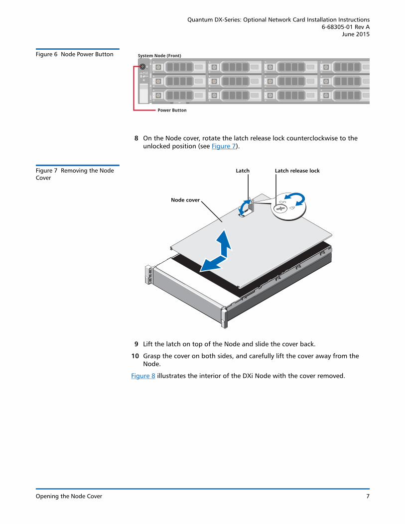
Figure 6 Node Power Button
8 On the Node cover, rotate the latch release lock counterclockwise to the unlocked position (see Figure 7).
Figure 7 Removing the Node Cover
9 Lift the latch on top of the Node and slide the cover back.
10 Grasp the cover on both sides, and carefully lift the cover away from the Node.
Figure 8 illustrates the interior of the DXi Node with the cover removed.
Power Button
System Node (Front)
Node cover
Latch Latch release lock
Opening the Node Cover 7
Quantum DX-Series: Optional Network Card Installation Instructions6-68305-01 Rev AJune 2015
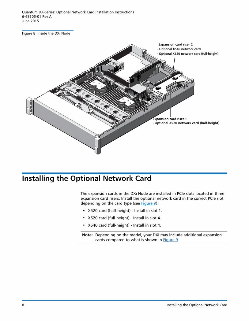
Figure 8 Inside the DXi Node
Installing the Optional Network Card
The expansion cards in the DXi Node are installed in PCIe slots located in three expansion card risers. Install the optional network card in the correct PCIe slot depending on the card type (see Figure 9).
• X520 card (half-height) - Install in slot 1.
• X520 card (full-height) - Install in slot 4.
• X540 card (full-height) - Install in slot 4.
Note: Depending on the model, your DXi may include additional expansion cards compared to what is shown in Figure 9.
10
23
10
23
Expansion card riser 1 - Optional X520 network card (half-height)
Expansion card riser 2- Optional X540 network card- Optional X520 network card (full-height)
8 Installing the Optional Network Card

Quantum DX-Series: Optional Network Card Installation Instructions6-68305-01 Rev A
June 2015
Figure 9 Optional Network Card Location
Installing the Half-Height X520 Network Card
To install the optional half-height X520 network card in the DXi Node:
Caution: Use appropriate ESD precautions, including the use of a grounding strap, when performing this procedure.
1 Holding the touch points, lift the expansion card riser 1 from the riser connector on the system board (see Figure 10).
Figure 10 Removing and Installing the Expansion Card Riser 1
- Install half-height X520 network card in slot 1
Node rear
1
2
3
4
5
6
7
- Install full-height X540 network card in slot 4
- Install full-height X520 network card in slot 4
Touch pointsExpansion card riser 1
Back riser guidesFront riser guide
Expansion card riser 1 connector
Installing the Optional Network Card 9

Quantum DX-Series: Optional Network Card Installation Instructions6-68305-01 Rev AJune 2015
2 Press the tab to release the expansion card latch and rotate the latch away from the expansion card riser (see Figure 11).
Note: Depending on the DXi model, one or more expansion cards may already be installed in expansion card riser 1. Do not remove any installed cards from expansion card riser 1.
Figure 11 Installing the Optional Network Card in Riser 1
3 Remove the metal slot cover from sliding it out of slot 1.
4 Holding the network card by its edges, position the card so that the card edge connector aligns with the expansion card connector.
5 Insert the card edge connector firmly into the expansion card connector until the card is fully seated. Make sure the card is inserted into slot 1.
6 Close the expansion card latch.
7 Holding the touch points, insert the expansion card riser 1 into the riser connector on the system board (see Figure 11).
8 (Optical 10 GbE option only) Insert an SFP+ unit into each 10 GbE port on the X520 card. (The SFP+ units are included with the optional 10 GbE network card.)
Installing the Full-Height X520 Network Card
To install the optional full-height X520 network card in the DXi Node:
Caution: Use appropriate ESD precautions, including the use of a grounding strap, when performing this procedure.
1 Lift the expansion card latch out of the slot (see Figure 12).
Expansion card connector
Network card
Expansion card latch tab
10 Installing the Optional Network Card

Quantum DX-Series: Optional Network Card Installation Instructions6-68305-01 Rev A
June 2015
The expansion card latch is located to the right of PCIe slot 4 as you face the rear of the Node. the latch will remain attached to the system.
Figure 12 installing the Full-Height X520 Card in Riser 2
2 Remove the metal slot cover from slot 4 by sliding it out of the slot.
3 Holding the X520 card by its edges, position the card so that the connector on the X520 card aligns with the expansion card connector on the riser.
4 Insert the card-edge connector firmly into the expansion card connector until the card is fully seated.
5 Push the expansion card latch down to lock the X520 card in place.
Installing the X540 Network Card
To install the X540 10 GBase-T network card in the DXi4700 Node:
Caution: Use appropriate ESD precautions, including the use of a grounding strap, when performing this procedure.
1 Lift the expansion card latch out of the slot (see Figure 13).
The expansion card latch is located to the right of PCIe slot 4 as you face the rear of the Node. the latch will remain attached to the system.
Expansion card
Expansion card latch
Expansion card connector
Expansion card riser
Installing the Optional Network Card 11

Quantum DX-Series: Optional Network Card Installation Instructions6-68305-01 Rev AJune 2015
Figure 13 installing the X540 Card in Riser 2
2 Remove the metal slot cover from slot 4 by sliding it out of the slot.
3 Holding the X540 card by its edges, position the card so that the connector on the X540 card aligns with the expansion card connector on the riser.
4 Insert the card-edge connector firmly into the expansion card connector until the card is fully seated.
5 Push the expansion card latch down to lock the X540 card in place.
Expansion card
Expansion card latch
Expansion card connector
Expansion card riser
12 Installing the Optional Network Card

Quantum DX-Series: Optional Network Card Installation Instructions6-68305-01 Rev A
June 2015
Closing the Node Cover
To close the DXi Node cover:
1 Lift the latch on the cover (see Figure 14).
Figure 14 Replacing the Node Cover
2 Place the cover onto the Node chassis and offset the cover slightly back so that it clears the chassis hooks and lays flush on the chassis.
3 Push down the latch to move the cover into the closed position.
4 Rotate the latch release lock in a clockwise direction to secure the cover.
5 Pull the inner slide rails out of the rack until they lock into place (see Figure 15).
Node cover
Latch Latch release lock
Closing the Node Cover 13

Quantum DX-Series: Optional Network Card Installation Instructions6-68305-01 Rev AJune 2015
Figure 15 Installing the DXi Node in the Rack
6 Locate the rear rail standoff on each side of the Node and lower them into the rear J-slots on the slide assemblies.
7 Rotate the Node downward until all the rail standoffs are seated in all four of the J-slots.
8 Press the slide-release lock buttons on both rails and slide the Node into the rack. (Make sure the Node is squarely aligned with the rack as you slide it in.)
9 If applicable, replace the front bezel by inserting the right side of the bezel into the slots on the Node and then snapping the left side of the bezel into place.
10 Reconnect all power, SAS, Ethernet, and Fibre Channel cables on the rear of the Node.
Note: For detailed system cabling information, see the Installation Guide for your DXi system.
11 Connect Ethernet cables to the ports on the new network card:
• Dual port 10 GbE (X520) card - Connect up to two 10 GbE cables (optical or Twinax).
• Dual port 10GBase-T (X540) card - Connect up to two 10 GBase-T CAT6 cables.
Inner slide rails
Rear rail standoffs
Rear rail J-slots
Slide-release lock button
Lock lever
Front of Node
14 Closing the Node Cover

Quantum DX-Series: Optional Network Card Installation Instructions6-68305-01 Rev A
June 2015
Turning On the System
To turn on the system:
1 Turn on each Array or Expansion module (if any):
Note: For detailed information about turning on Array or Expansion modules, see the User’s Guide for your DXi system.
• Turn on both power switches on the back of each Expansion module (JBOD). Wait 30 seconds for the Expansion modules to initialize.
2 Press the power button on the front of the Node (see Figure 16). Wait for the system to boot. (This can take up to 30 minutes.)
Figure 16 Node Power Button
3 Navigate to the Configuration > System > Network page in the remote management console and verify that the new network ports are available to the DXi.
The new ports should display under Bonding Details and Interface Details. They should also display on the Backpanel Locations diagram at the bottom of the page.
The new ports are numbered E4 and E5.
Note: The current network configuration is not changed when adding the additional network card. To make use of the additional Ethernet ports, edit the settings on the Network page as needed.
Power Button
System Node (Front)
Turning On the System 15