quantum nondemolition measurement of mechanical motion …
TRANSCRIPT

ARTICLE
Quantum nondemolition measurementof mechanical motion quantaLuca Dellantonio1,2, Oleksandr Kyriienko 1,3, Florian Marquardt 4,5 & Anders S. Sørensen 1,2
The fields of optomechanics and electromechanics have facilitated numerous advances in the
areas of precision measurement and sensing, ultimately driving the studies of mechanical
systems into the quantum regime. To date, however, the quantization of the mechanical
motion and the associated quantum jumps between phonon states remains elusive. For
optomechanical systems, the coupling to the environment was shown to make the detection
of the mechanical mode occupation difficult, typically requiring the single-photon strong-
coupling regime. Here, we propose and analyse an electromechanical setup, which allows
us to overcome this limitation and resolve the energy levels of a mechanical oscillator.
We found that the heating of the membrane, caused by the interaction with the environment
and unwanted couplings, can be suppressed for carefully designed electromechanical
systems. The results suggest that phonon number measurement is within reach for modern
electromechanical setups.
DOI: 10.1038/s41467-018-06070-y OPEN
1 The Niels Bohr Institute, University of Copenhagen, Blegdamsvej 17, 2100 Copenhagen Ø, Denmark. 2 Center for Hybrid Quantum Networks (Hy-Q), TheNiels Bohr Institute, University of Copenhagen, Blegdamsvej 17, 2100 Copenhagen Ø, Denmark. 3 NORDITA, KTH Royal Institute of Technology andStockholm University, Roslagstullsbacken 23, 106 91 Stockholm, Sweden. 4 Institute for Theoretical Physics, University Erlangen-Nürnberg, Staudstraße 7,91058 Erlangen, Germany. 5Max Planck Institute for the Science of Light, Günther-Scharowsky-Straße 1, 91058 Erlangen, Germany. Correspondence andrequests for materials should be addressed to L.D. (email: [email protected])
NATURE COMMUNICATIONS | (2018) 9:3621 | DOI: 10.1038/s41467-018-06070-y | www.nature.com/naturecommunications 1
1234
5678
90():,;
Energy quantization is one of the hallmarks of quantummechanics. First theorized for light by Einstein and Planck,it was found to be ubiquitous in nature and represents a
cornerstone of modern physics. It has been observed in variousmicroscopic systems starting from nuclei, atoms and molecules,to larger mesoscopic condensed matter systems such as super-conductors1. For macroscopic systems, however, the observationof energy quantization is hindered by the smallness of the Planckconstant. Thus, although being a milestone of contemporaryphysics, up to date the discrete energy spectrum of mechanicalresonators has never been seen directly.
Extreme progress in studying mechanical systems has beenachieved in experiments exploiting radiation pressure. This is thecore of optomechanics2, where photons and phonons of theoptical and mechanical subsystems interact with each other. Asimilar type of coupling can be realized in the microwave domainwith electrical circuits, leading to the field of electromechanics3–8.The numerous advances of optomechanics and electromechanicsinclude ground state cooling4,5,9–11, ultra precise sensing12–15,generation of squeezed light and mechanical states7,8,16–18, backaction cancellation19,20 and detection of gravitational waves21. Inall of these systems, however, the operation in the single-photon/phonon regime is challenging due to the small value of the barecoupling3,22. Instead, experiments exploit an enhanced linearizedeffective coupling induced by a large driving field. This severelylimits the nature of the interactions23 and possible quantumeffects. In particular, it precludes the observation of the energyquantization in mechanical resonators.
Quantization of mechanical energy can be observed by aquantum nondemolition (QND) measurement24,25 of an oscilla-tor’s phonon number operator nb. Here, QND means thatthe interaction, which couples the mechanical system with themeasurement apparatus, does not affect the observable we areinterested in. This is achieved if the total Hamiltonian commuteswith nb, and the influence of the environment is minimized.
Considering the electromechanical setups in Fig. 1, we showthat QND detection is feasible for a capacitor in which one of theelectrodes is a light micromechanical oscillator. By choosing anantisymmetric mode for the oscillator, the interaction betweenthe electrical and mechanical subsystems is quadratic in thedisplacement. Along with the suppression of the linear coupling,this ensures the QND nature of the measurement, as originallyproposed in refs. 26,27 for an optomechanical system. In thatsystem, however, it was shown in refs. 28,29 that the combinationof unwanted losses and the coupling to an orthogonal electro-magnetic mode spoils the interaction, unless strong single-photoncoupling is achieved. Here, we show that for the consideredelectromechanical setup the equivalent orthogonal mode can havedramatically different properties, allowing for the phonon QNDdetection. We derive general conditions under which the QNDmeasurement is possible, and characterize its experimental sig-natures. As compared to most approaches to phonon QNDmeasurement26,27,30–32, our procedure does not impose stringentrequirements on the single-photon optomechanical coupling,but relies on the ratio of the involved coupling constants. Thismakes our approach attractive even for systems where theinteraction is limited, for example, due to stray capacitances inthe setup. For a measurement of the square displacement, asimilar advantage was identified in ref. 31.
ResultsProceeding. We first study an RLC circuit with one capacitorplate being an oscillating membrane, without assuming thesymmetry discussed above (Fig. 1b). The mechanical motion ofthe plate shifts the resonance frequency of the circuit, while the
electric potential exerts a force on the membrane. In order toperform a QND measurement of the phonon number, we requirethis interaction to be proportional to nb. We therefore Taylorexpand the inverse of the capacitance to second orderin the displacement, 1=CðxÞ≃ C�1
0 + ~g1ðbþ byÞ+ ~g2ðbþ byÞ2=2,where we replaced the position x with the creation byand annihilation b operators of the mechanical motion, and ~g1;2denote linear and quadratic coupling constants. Within therotating wave approximation, ~g2ðbþ byÞ2=2≃ ~g2nb, leading to thedesired QND interaction, while the ~g1 term adds unwantedheating that spoils the phonon measurement.
The main aim of this work is to identify conditions underwhich the QND measurement is feasible, despite the presence ofheating. We initially consider the simple circuit in Fig. 1b, andassume the incoming signal Vin to be in a coherent state resonantwith the circuit. The quadratic interaction then shifts theelectrical resonance frequency proportionally to the phononnumber ~g2nb. For small ~g2, this shift leads to a phase change of theoutgoing signal Vout that can be determined by homodynemeasurement. Different phononic states will thus lead to distinctoutcomes VM, as shown in Fig. 2. The distance d between outputsignals for different nb and the standard deviation σ of the noisedefine the signal-to-noise ratio D= d/σ (see Fig. 2), which needsto be maximized.
In order to have a successful QND measurement, the phononnumber nb must be conserved. If the mechanical state jumps duringa measurement, the outcome VM ends up between the desiredpeaks. This leads to a reduced contrast, as illustrated by thedistribution in the background of Fig. 2. The probability for nb tochange is generally state-dependent, in the sense that higher Fockstates are more likely to jump. A state-independent characterizationof this heating is given by the average phonons Δnb added to theground state during the measurement time T. The jump probabilityfor any state can then be derived from Δnb using standard resultsfor harmonic oscillators (for details see Supplementary Note 3available in Supplementary Material online).
Both D and Δnb are proportional to the incoming intensity. Wetherefore characterize a setup by the parameter λ=D2/Δnb,where λ � 1 is required for successful QND detection. For theRLC circuit in Fig. 1b, we find below that
λ ¼ 1
2 1þ 2�neð Þ2g2g1
� �2 ωm
γt
� �2
; ð1Þ
where g1 ¼ ~g1C0ωs, g2 ¼ ~g2C0ωs and �ne is the thermal occupationof R0 and Zout (assumed equal, R0= Zout). Here, ωm andωs= (C0L0)−1/2≫ ωm are the mechanical and electrical frequen-cies, respectively, and γt= Zout/L0 corresponds to the outputcoupling rate. A result similar to Eq. (1) is derived in ref. 33.
Despite progresses in reaching the resolved sideband regimeωm � γt in both optomechanical and electromechanical systems,g2 is generally much smaller than g1, implying λ � 1 in Eq. (1).To circumvent this problem, we use the second fundamentalmode of the membrane in the capacitor, as depicted in Fig. 1a.The first-order coefficient ~g1 of the 1=CðxÞ expansion thenvanishes, leaving ~g2 to be the largest contribution to theelectromechanical coupling. In this situation λ seemingly growsindefinitely, the induced heating disappears and the QNDmeasurement of the phonon number is easily realized. Inpractice, however, two effects will limit the achievable value ofλ. First, inaccuracies in the nanofabrication can cause misalign-ments and, consequently, a residual linear coupling. Second, theoscillation of the membrane induces a charge redistribution inthe capacitor to maintain it at an equipotential. The associatedantisymmetric electrical mode introduces an effective linearcoupling, and a similar heating mechanism as the one identified
ARTICLE NATURE COMMUNICATIONS | DOI: 10.1038/s41467-018-06070-y
2 NATURE COMMUNICATIONS | (2018) 9:3621 | DOI: 10.1038/s41467-018-06070-y | www.nature.com/naturecommunications

in ref.28 for the optomechanical setup of refs26,27. In these papers,the quadratic interaction results from a hybridization of twomodes linearly coupled to the mechanical position, and the QNDdetection was found to be impossible unless the single-photoncoupling g1 exceeded the intrinsic cavity damping. In our case, theQND interaction arises directly from the Taylor expansion of thecapacitance. Hence, there is no constraint tying the second-ordercoupling g2 to the properties of the symmetric and antisymmetricelectrical modes, which can have vastly different resonancefrequencies and dampings. This inhibits the mechanical heatingand ultimately allows for the QND detection of the phononnumber. We model the charge redistribution in the capacitor byparasitic inductances (L) and resistances (R) in the equivalentcircuit of Fig. 1c. Each of the two arms containing R and Lrepresents one half of the capacitor, with opposite dependence onthe membrane position, CðxÞ and Cð�xÞ.
Single-arm RLC circuit. In the following, we derive Eq. (1) forthe RLC circuit in Fig. 1b. The methods sketched here willthen be generalised for the double-arm circuit in Fig. 1c. Usingthe standard approach34, we write the circuit Hamiltonianas HðxÞ= Φ
2= 2L0½ � þ Q2= 2CðxÞ½ �, where the conjugate variables
Q and Φ are the charge and magnetic flux, respectively. Wecan expand HðxÞ in the mechanical position x / bþ by, inorder to obtain the circuit Hamiltonian He = H x ¼ 0ð Þand the coupling Hamiltonian Hem = g1ωsL0Q
2ðbþ byÞ=2+g2ωsL0Q
2ðnb þ bb=2þ byby=2Þ. The total Hamiltonian Htot =He þ Hem þ Hm is therefore the sum of the circuit, interactionand the mechanical Hamiltonian Hm = �hωmb
yb.
Next, we describe the environmental effects corresponding todecay and heating of the modes. Associating each resistor Ri withits own Johnson–Nyquist noise VRi
, we find the equations ofmotion of the composite system
:
Q ¼ Φ
L0; ð2Þ
:
Φ ¼ � QC0� γt þ γr� �
Φ� g1ωsL0Q bþ by� �
�g2ωsL0Q nb þ bbþby by2
� �þ 2 Vin þ VR0
� �;
ð3Þ
:
b ¼ �iωmb� g1iωsL0Q
2
2�h� g2
iωsL0Q2
2�hbþ by
� �� γb
2bþ i
x0�hFb;
ð4Þwhere γr= R0/L0, γb is the intrinsic mechanical dampingrate with associated noise Fb and x0=
ffiffiffiffiffiffiffiffiffiffiffiffiffiffiffiffiffiffiffiffiffi�h= 2mωmð Þp
is theamplitude of the zero-point motion for a membrane ofmass m. From now on, we consider optimally loaded setupswith γr= γt. Equations (2)–(4) fully characterize the dynamicsof the system, and represent the starting point for our detailedanalysis.
C (x)
Vin
VoutZ
out V
in
VoutZ
out
C (x) C (–x)
R0R0
RRL0
L0
L L
a
b c
Fig. 1 Experimental setup. a Sketch of a capacitor with an oscillating plate, here represented by a graphene membrane. We consider an antisymmetric (2, 1)mechanical mode. b RLC oscillator formed by the inductance L0, resistance R0, and position-dependent capacitance CðxÞ. The circuit is driven by the inputvoltage Vin through a transmission line of impedance Zout. Vout is the reflected signal. c Model circuit for an RLC system where the capacitor has the sameform as in a. The membrane has a vanishing linear coupling to the symmetric electrical mode used for probing the system. The antisymmetric mode,residing in the small loop containing parasitic inductances L and resistances R, describes the redistribution of charge on the capacitor
NATURE COMMUNICATIONS | DOI: 10.1038/s41467-018-06070-y ARTICLE
NATURE COMMUNICATIONS | (2018) 9:3621 | DOI: 10.1038/s41467-018-06070-y | www.nature.com/naturecommunications 3

The feedback of the membrane’s motion on the electricalcircuit is described by Eq. (3). Driving the system at the electricalresonance frequency ωs, the terms proportional to g1ðbþ byÞ andg2ðbbþ bybyÞ give rise to sidebands at frequencies ωs ± ωm andωs ± 2ωm, respectively, whereas g2nb induces a phonon-dependentfrequency shift of the microwave cavity. Since homodynedetection is only sensitive to signals at the measured frequency,the sidebands are removed in the outcome VM, which is definedas the phase quadrature of Vout ¼ Vin � γtΦ. This allows us toneglect oscillating terms in the calculation of VM (the linear termalso leads to mechanically induced damping, but this is typicallynegligible compared to γt). The only contribution to VM istherefore the phonon-dependent frequency shift, which allows usto resolve the mechanical state. On the contrary, the electricallyinduced mechanical heating only involves the sidebands ωs ± ωm
and ωs ± 2ωm, being unaffected by the term g2nb in theHamiltonian. For the RLC circuit in Fig. 1b, the heating isdominated by the linear term, since g1 � g2, and we shall neglectg2 for the calculation of Δnb.
Below, we quantify the heating of the membrane and thephonon-dependent LC frequency shift. We first assume that themechanical state does not jump during the measurement. Then,the equations of motion of the two subsystems decouple and wefind D2= g22 αj j2= 4ð1þ 2�neÞγ2t
, where the number of photons
αj j2 sent into the circuit within the measurement time T sets themeasurement strength. As discussed above, Δnb is the averagephonon number at the end of the measurement Δnb= nbðTÞh i,with the mechanics initially in its ground state. For T muchshorter than the mechanical lifetime γ�1
b , Δnb can be linearized tofind the rate at which the membrane heats up. For the RLC circuitin Fig. 1b, we find Δnb= 1þ 2�neð Þg21 αj j2= 2ω2
m
� �. The parameter
λ given in Eq. (1) is then found as the ratio λ=D2/Δnb. Fordetails see Supplementary Note 1 available in SupplementaryMaterial online.
Double-arm circuit. With the overall linear coupling vanishing,the parameter λ will be limited by fabrication imperfections andcoupling to the antisymmetric mode. To model these phenomena,
we consider the circuit in Fig. 1c, where the antisymmetric moderesides inside the small loop containing the two capacitors, andthe symmetric one probes the system. We derive g1 and g2 fromthe expansion of each of the two capacitors: 1=C ± xð Þ≃C�10 ± ~g1ðbþ byÞ þ ~g2nb, so that in the absence of fabrication
imperfections the total capacitor Ctot= C xð Þ þ C �xð Þ is notlinearly coupled to the symmetric mode. The coefficients g1 andg2 are related to their tilde counterparts in the same way as before,and the parameters D2 and Δnb are evaluated in a similar fashionas we did for the RLC circuit. Since we quantify two sources ofheating, it is convenient to write λ= ðλ�1
b þ λ�1p Þ�1, where λb
takes into account heating from charge redistribution, and λpdescribes the influence of fabrication imperfections. With thedetails presented in Supplementary Note 2 (for details, see Sup-plementary Material available online) and Methods, we find
λb ¼2
1þ 2�neð Þ2g2g1
� �2 ωs
γt
� �2Zout
R; ð5Þ
λp ¼2
1þ 2�neð Þ2g2g1
� �2 g1gr
� �2 ωm
γt
� �2
; ð6Þ
where ωs= [C0(L+ 2L0)]−1/2 is the frequency of the symmetricmode, γt= [2Zout]/[L+ 2L0] is the decay to the transmission lineand gr= 2C0x0ωs∂xC
�1tot ðxÞ is the residual linear coupling induced
by fabrication imperfection. We use the same notation introducedfor the RLC circuit to allow a direct comparison. Equations (5)and (6) express the gain of our approach to QND detection. First,Eq. (6) quantifies the advantage of symmetry: λ dramaticallyimproves compared to Eq. (1) by having a small residual linearcoupling gr � g1. Second, Eq. (5) is multiplied by the factor(ωs/ωm)2 with respect to Eq. (1). For microwave readout of amegahertz oscillator, this factor can be substantial. Furthermore,the mechnical oscillator is now only susceptible to the noiseassociated with charge redistribution on the capacitor, and not tothe resistance in the inductor. This gives an additionalimprovement if R < Zout.
JumpslR
l1
l0 d
Out
com
es
nb = 0 nb = 1VM
�
�
Fig. 2 Sketch of the experimental outcome. Distribution of outcomes VM for two different phonon numbers: nb= 0 (first peak to the left) and nb= 1(last peak to the right). For a given value of nb, repeated measurements are Gaussian distributed with a variance σ2 / 1þ 2�ne of the outgoing signal Vout,consisting of vacuum and thermal noise. The distance d between the two peaks depends on the circuit parameters and the number of incident photons, andidentifies the signal-to-noise ratio D= d/σ. Ideally, for each shot of the measurement, the mechanics is either in its ground or first excited state. However,for Δnb > 0 there will be events where the mechanical state jumps, resulting in outcomes VM in between the peaks relative to nb= 0 and nb= 1(smaller peaks in the figure). This leads to the smeared distribution shown in the back. The visibility of the QND measurement is quantified by the valuesat the peaks and valleys, as indicated by I0, I1 and IR (see Eq. (9)). The figure is for illustration only, and is not to scale
ARTICLE NATURE COMMUNICATIONS | DOI: 10.1038/s41467-018-06070-y
4 NATURE COMMUNICATIONS | (2018) 9:3621 | DOI: 10.1038/s41467-018-06070-y | www.nature.com/naturecommunications
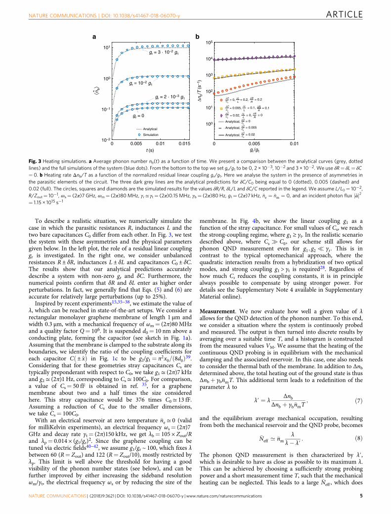
To describe a realistic situation, we numerically simulate thecase in which the parasitic resistances R, inductances L and thetwo bare capacitances C0 differ from each other. In Fig. 3, we testthe system with these asymmetries and the physical parametersgiven below. In the left plot, the role of a residual linear couplinggr is investigated. In the right one, we consider unbalancedresistances R ± δR, inductances L ± δL and capacitances C0 ± δC.The results show that our analytical predictions accuratelydescribe a system with non-zero gr and δC. Furthermore, thenumerical points confirm that δR and δL enter as higher orderperturbations. In fact, we generally find that Eqs. (5) and (6) areaccurate for relatively large perturbations (up to 25%).
Inspired by recent experiments15,35–38, we estimate the value ofλ, which can be reached in state-of-the-art setups. We consider arectangular monolayer graphene membrane of length 1 μm andwidth 0.3 μm, with a mechanical frequency of ωm= (2π)80MHzand a quality factor Q= 106. It is suspended d0= 10 nm above aconducting plate, forming the capacitor (see sketch in Fig. 1a).Assuming that the membrane is clamped to the substrate along itsboundaries, we identify the ratio of the coupling coefficients foreach capacitor Cð± xÞ in Fig. 1c to be g2/g1= π2x0= 8d0ð Þ39.Considering that for these geometries stray capacitances Cs aretypically preponderant with respect to C0, we take g1≃ (2π)7 kHzand g2≃ (2π)1 Hz, corresponding to Cs≃ 100C0. For comparison,a value of Cs= 50 fF is obtained in ref. 35, for a graphenemembrane about two and a half times the size consideredhere. This stray capacitance would be 376 times C0≃ 13 fF.Assuming a reduction of Cs due to the smaller dimensions,we take Cs= 100C0.
With an electrical reservoir at zero temperature �ne ≃ 0 (validfor milliKelvin experiments), an electrical frequency ωs= (2π)7GHz and decay rate γt= (2π)150 kHz, we get λb= 105 × Zout/Rand λp= 0.014 × (g1/gr)2. Since the graphene coupling can betuned via electric fields40–42, we assume g1/gr ~ 100, which fixes λbetween 60 (R= Zout) and 122 (R= Zout/10), mostly restricted byλp. This limit is well above the threshold for having a goodvisibility of the phonon number states (see below), and can befurther improved by either increasing the sideband resolutionωm/γt, the electrical frequency ωs or by reducing the size of the
membrane. In Fig. 4b, we show the linear coupling g1 as afunction of the stray capacitance. For small values of Cs, we reachthe strong-coupling regime, where g1 ≥ γt. In the realistic scenariodescribed above, where Cs � C0, our scheme still allows forphonon QND measurement even for g1; g2 � γt . This is incontrast to the typical optomechanical approach, where thequadratic interaction results from a hybridization of two opticalmodes, and strong coupling g1 > γt is required28. Regardless ofhow much Cs reduces the coupling constants, it is in principlealways possible to compensate by using stronger power. Fordetails see the Supplementary Note 4 available in SupplementaryMaterial online).
Measurement. We now evaluate how well a given value of λallows for the QND detection of the phonon number. To this end,we consider a situation where the system is continuosly probedand measured. The output is then turned into discrete results byaveraging over a suitable time T, and a histogram is constructedfrom the measured values VM. We assume that the heating of thecontinuous QND probing is in equilibrium with the mechanicaldamping and the associated reservoir. In this case, one also needsto consider the thermal bath of the membrane. In addition to Δnbdetermined above, the total heating out of the ground state is thusΔnb+ γb�nmT. This additional term leads to a redefinition of theparameter λ to
λ′ ¼ λΔnb
Δnb þ γb�nmT; ð7Þ
and the equilibrium average mechanical occupation, resultingfrom both the mechanical reservoir and the QND probe, becomes
�Neff ’ �nmλ
λ� λ′: ð8Þ
The phonon QND measurement is then characterized by λ′,which is desirable to have as close as possible to its maximum λ.This can be achieved by choosing a sufficiently strong probingpower and a short measurement time T, such that the mechanicalheating can be neglected. This leads to a large �Neff , which does
105
104
103
102
Δnb/
T (
s–1 )
101
100
0 0.005 0.01gr /g1
100
101
gr = 10–2 g1
gr = 2 · 10–3 g1
gr = 3 · 10–2 g1
gr = 0
⟨nb⟩
10–1
10–20 0.005
Analytical
Simulation
0.01 0.015
t (s)
�C �L �RRC0 L
= 0, = 0.2, = 0.2
�CC0
�LL
= 0.02, = 0, �RR
= 0
�CC0
�L
L= 0.005, = 0.1, �R
R= 0.1
= 0Analytical, �CC0
Analytical, = 0.005C0
�C
Analytical, = 0.02�CC0
a b
Fig. 3 Heating simulations. a Average phonon number nb(t) as a function of time. We present a comparison between the analytical curves (grey, dottedlines) and the full simulations of the system (blue dots). From the bottom to the top we set gr/g1 to be 0, 2 × 10⁻³, 10−2 and 3 × 10⁻². We use δR= δL= δC= 0. b Heating rate Δnb/T as a function of the normalized residual linear coupling gr/g1. Here we analyse the system in the presence of asymmetries inthe parasitic elements of the circuit. The three dark grey lines are the analytical predictions for δC/C0 being equal to 0 (dotted), 0.005 (dashed) and0.02 (full). The circles, squares and diamonds are the simulated results for the values δR/R, δL/L and δC/C reported in the legend. We assume L/L0= 10−2,R/Zout= 10−1, ωs= (2π)7 GHz, ωm= (2π)80MHz, γr≃ γt= (2π)0.15MHz, γb= (2π)80 Hz, g1= (2π)7 kHz, �ne ¼ �nm ¼ 0, and an incident photon flux ~αj j2= 1.15 × 10¹⁵ s−1
NATURE COMMUNICATIONS | DOI: 10.1038/s41467-018-06070-y ARTICLE
NATURE COMMUNICATIONS | (2018) 9:3621 | DOI: 10.1038/s41467-018-06070-y | www.nature.com/naturecommunications 5

not significantly change the contrast of the QND measurement(see Eq. (10) and Fig. 5b), but increases the time for acquiringsignificant statistics (the mechanical system spends less time ineach Fock state).
Given λ′, we now want to optimize all remaining parametersof the system, to be able to discern the ground and first excitedstates with the largest contrast. We simulate the mechanicalsystem with the quantum-jump method, and pick Gaussiandistributed random values for the electrical vacuum and thermalnoise. From this, we make the histogram of the resulting outputvoltages VM presented in Fig. 5a, where the induced heatingΔnb is optimized numerically. For the optimization we considerthe visibility
ξ ¼12 I0 þ I1ð Þ � IR12 I0 þ I1ð Þ þ IR
; ð9Þ
where I0 and I1 are the heights of the peaks correspondingto nb= 0 and nb= 1 phonons, while IR is the lowest height inbetween I0 and I1 (see Fig. 2).
Additionally, we make an analytical model where we allow forone jump during each measurement period. We can extract theasymptotic behaviour of the visibility
ξ λ′; �Neffð Þ ¼ 1� 83þ 5�Neff
1þ 2�Neff
ffiffiffiffiffiffiffiffiffiffiffiffiffiffiπ logλ′
pλ′
; ð10Þ
reflecting the compromise between the contributions to IRfrom the noise ∝ exp(−D2/8) and from the jumps during themeasurements ∝ Δnb.
The results of simulations and model are shown in Fig. 5a. Theblue points are the numerical optimization, which are in goodagreement with the analytical result (red, dotted line). Notice thatfor small values of λ′, the optimal Δnb is sufficiently high to allowmultiple jumps during the measurement time T, leading to minor
discrepancies. The black, solid line is Eq. (10), and the shadowedregion corresponds to the predicted values of λ for the parametersintroduced above. Qualitatively, clear signatures of the mechan-ical energy quantization are present for λ′≳ 40, where thevisibility exceeds 20%.
For the experimental parameters considered above, themaximum attainable value of λ′ is λ= 122 (for R= Zout/10),and is achieved with a strong probe such that �Neff � �nm. Theincident power and the measurement time T provide a handle tooptimize the performance for given experimental conditions.Qualitatively, a short value of T minimizes the effects of themechanical heating, and makes λ′≃ λ. On the other hand, therequired power to reach such a regime can be troublesome43, andwe may need to integrate for too long time to have sufficientstatistics (since �Neff � 1). This last problem can be solved byadding an electrical cooling, red-detuned by ωm � γt from theQND probe. This cooling would not affect the parameter λ′, sinceit does not heat up the system, but only reduces �Neff . The visibilityξ thus remains almost unaltered (see Eq. (10) and Fig. 5b), butthe probability to find the membrane in low excited states isincreased, reducing the experimental time.
As an example, assume that the heating from the electricalfeedback and the mechanical bath are equal, such that λ′= λ/2=61. Considering a cryogenic temperature of 14mK37, the averagemechanical occupation is �nm ≃ 3, implying �Neff ¼ 6. The optimalΔnb is then 0.3, and can be obtained with a driving power of 16 nWand a measurement time of 0.1 ms for a mechanical quality factorQ= 106 and a stray capacitance Cs= 100C0. For other values of Qand Cs, the driving power can be varied to fulfil the constraint�Neff ¼ 2�nm, as shown in Fig. 4a. The incident field is ratherintense, which may cause additional heating to the system. In theset up of ref. 43, such additional heating has been observed abovean intracavity photon number of 108. For comparison, in Fig. 4awe show the intracavity photon number ~αj j2=γt for our system,where ~αj j2¼ αj j2=T is the photon flux. Depending on theparameters, we see that ~αj j2=γt will be similar or higher than 108
for Cs≳ 100C0. These devices cannot, however, be compareddirectly. Nevertheless, since ref. 43 indicates that the source of thisheating is electrical, we believe that it would be strongly suppressedfor the QND measurement considered here. Since the linearcoupling is almost cancelled by symmetry, the resulting heatingrate is likely reduced by a factor (gr/g1)2≃ 10−4. In absence of thissuppression, conducting our experiment in a pulsed regime maysubstantially reduce other heating mechanisms.
DiscussionWe have revisited the challenge of performing a phonon QNDmeasurement. Employing symmetry to inhibit the linear cou-pling, the detrimental heating is suppressed while retaining thedesired quadratic coupling. Contrary to the generally studiedoptomechanical case28, the residual coupling to the antisym-metric mode is strongly suppressed by its higher frequency andreduced resistance. A particularly attractive feature of the currentapproach is that it is only sensitive to the ratio g2/g1, and not totheir absolute values. Stray capacitances, which reduce theelectromechanical couplings, can thus be compensated usingstronger input fields.
These attractive features put QND detection within reach ofpresently available technology. A successful realization of a QNDdetection will not only represent a demonstration of genuine non-classical behaviour of mechanical systems, but also extend theinteractions available in electro/optomechanics to non-Gaussianoperations44. This will considerably expand the realm of effectsthat can be studied with these systems, and facilitate theirapplication for quantum information processing23.
1012
100 nW
10 nW
1 μW
1 nW
100 pW
10 pW
g1 ≥ �t
Strongcoupling
1010
|~ α|2
/ �t
108
106
106
g 1/2�
(H
z)
104
102
100 3.8 101 102
Q = 107
Q = 106
Q = 105
103
CS/C0
a
b
Fig. 4 Operating conditions in the presence of stray capacitances.a Average intracavity photons ~αj j2=γt required for the QND measurement,as a function of the relative value of the stray capacitance Cs/C0. The threelines correspond to different values of the mechanical quality factor, asindicated in the legend. We assume Δnb= 0.3 and equal contributions fromthe mechanical and electrically induced reservoirs �nm ¼ �Neff=2 ¼ 3. As areference, the grey dashed lines indicate the associated powers of theprobe. b Linear coupling g1 as a function of Cs/C0. For both figures, theshadowed region indicates the strong coupling g1≥ γt, where QNDdetection is feasible with other approaches26, 31, 32
ARTICLE NATURE COMMUNICATIONS | DOI: 10.1038/s41467-018-06070-y
6 NATURE COMMUNICATIONS | (2018) 9:3621 | DOI: 10.1038/s41467-018-06070-y | www.nature.com/naturecommunications

As an outlook, it is desirable to extend this work to theoptomechanical case, where mechanical systems with a similarquadratic coupling have recently been studied33,45,46, but condi-tions to have a successful phonon QND measurement have notbeen yet determined. The electromechanical systems consideredhere can be described with Kirchoff’s laws, which give rigorousresults within a well-defined model. The physical mechanismsbehind the heating are identified to be the Johnson–Nyquistnoises associated to the resistors, and fabrication imperfections.For comparison, the exact description of dissipation in a multi-mode optomechanical system may be more involved. Never-theless, the results presented here could be useful for guiding theintuition towards QND detection in the optical regime. As afurther extension, it would be interesting to investigate the effectof squeezing. By reducing the vacuum noise, squeezing can leadto a direct improvement in λ, thus reducing the physicalrequirements for the QND detection.
MethodsThe double-arm circuit. The Hamiltonian for the system in Fig. 1c is given by
H ¼ �hωmby bþ Φ
2a
4L þ Q2a
C0þ Φ
2s
Lþ2L0þ Q2
s4C0
þ g1C0ωs
QaQsðbþ byÞ þ g2C0ωs
Q2a b
y bþ g24C0ωs
Q2s b
yb;ð11Þ
where subscripts “a” and “s” indicate the asymmetric and the symmetricelectrical fields, respectively. From Eq. (11) and using Kirchoff’s laws, it ispossible to determine the equations of motions, including noises and decays.The normalized distance D2= d2/σ2 is obtained assuming the phonon number tobe constant within T—that is: setting g1= 0—so that the asymmetric andsymmetric fields decouple. Looking at the phase quadrature of the reflected signalVout ¼ Vin � γtΦs , we determine d. The noise σ is the sum of vacuum
noise from the input coherent field, and the Johnson–Nyquist noises of theresistors.
As discussed above, the heating Δnb ¼ nbðTÞh i has two contributions:asymmetries leading to a non-vanishing linear coupling gr, and the chargeredistribution. The first is found by assuming R � R0 and L � L0, such that thecircuit in Fig. 1c is equivalent to the one in Fig. 1b, for which we already know Δnb.The contribution from charge redistribution is determined from the Hamiltonianin Eq. (11) neglecting the quadratic interaction, which does not alter the phononnumber. The strongly driven symmetric electrical field is then substituted with itssteady state, obtained assuming a constant photon flux. The time evolution of nbh iis finally found by looking at the equations of motion for the asymmetric field andthe mechanical creation/annihilation operators. With the amplitude of thesymmetric mode replaced by its steady state, these equations are now linear in theannihilation (creation) operators b ðbyÞ and can be solved by standardoptomechanics techniques.
Asymmetric circuit. To obtain Fig. 3, we analyse the system in the presenceof asymmetries. First, we derive the generalization of the Hamiltonian in Eq. (11)with unequal rest capacitors, resistors, inductors and linear couplings.Differently from above, we linearize the symmetric/asymmetric electrical fieldsaround their mean values (Qa=s ! hQa=si þ δQa=s and ϕa=s ! hϕa=si þ δϕa=s),
and the mechanical creation/annihilation operators ðbðyÞ ! hbðyÞi þ δbðyÞÞ. Here,besides the usual oscillatory behaviour of the mechanical operators hbðyÞi, theamplitude is generally time dependent47. This can be understood by lookingat Eq. (11); since both the electrical fields have now non-zero average, thethree body interaction / QaQsðbþ byÞ is equivalent to a force directly drivingthe mechanical system. Once solutions for the averages are found, it ispossible to determine the variations, and finally the time evolution of thephonon number.
Optimization of the visibility. To obtain Fig. 5 we rely on both an analyticaland a numerical optimization of the visibility ξ. To determine the red, dottedcurve, we assume that the initial mechanical state is thermal, such that theoccupations of the Fock states can be found. Given Δnb, the probability tojump once either up or down during the measurement time T is a Poissonianprocess. The probability distribution function for the outcomes VM can then beobtained and maximized, by varying Δnb. The histograms and the blue pointsare derived with Monte Carlo simulations, where the time evolution of singlemechanical trajectories are replicated with the stochastic wave-function method48.Importantly, every measurement interval of duration T has been discretized,to allow for multiple jumps. The parameter Δnb is then varied to find the bestvisibility ξ.
Data availabilityAll material related to this work can be found at https://sid.erda.dk/share_redirect/eUaGoI8JbN.
Received: 5 February 2018 Accepted: 26 July 2018
References1. Martinis, J. M., Devoret, M. H. & Clarke, J. Energy-level quantization in the
zero-voltage state of a current-biased josephson junction. Phys. Rev. Lett. 55,1543–1546 (1985).
2. Aspelmeyer, M., Kippenberg, T. J. & Marquardt, F. Cavity optomechanics.Rev. Mod. Phys. 86, 1391 (2014).
3. Teufel, J. et al. Circuit cavity electromechanics in the strong-coupling regime.Nature 471, 204–208 (2011).
4. Teufel, J. D. et al. Sideband cooling of micromechanical motion to thequantum ground state. Nature 475, 359–363 (2011).
5. O’Connell, A. D. et al. Quantum ground state and single-phonon control ofa mechanical resonator. Nature 464, 697–703 (2010).
6. Heinrich, G. & Marquardt, F. Coupled multimode optomechanics in themicrowave regime. Europhys. Lett. 93, 18003 (2011).
7. Wollman, E. E. et al. Quantum squeezing of motion in a mechanical resonator.Science 349, 952–955 (2015).
8. Ockeloen-Korppi, C. F. et al. Noiseless quantum measurement and squeezingof microwave fields utilizing mechanical vibrations. Phys. Rev. Lett. 118,103601 (2017).
9. Chan, J. et al. Laser cooling of a nanomechanical oscillator into its quantumground state. Nature 478, 89–92 (2011).
10. Peterson, R. W. et al. Laser cooling of a micromechanical membraneto the quantum backaction limit. Phys. Rev. Lett. 116, 063601 (2016).
Out
com
es
102104
0.8
0.6
0.4
0.2
VM
VM
N–
eff = 1N–
eff = 10N–
eff = 100
�(�′
)
�′
Out
com
esa
b
Fig. 5 Visibility of the phonon QND measurement. a 3D plot: histograms ofoutcomes for different λ′ (from left to right, λ′= 32, 102, 3 × 10², 103, 3 ×10³ and 104). The optimal values of Δnb are (from left to right) 0.43, 0.27,0.12, 0.05, 2 × 10⁻³ and 8 × 10⁻⁴, and have been determined by anumerical optimization. The shadowed region corresponds to the estimatedvisibility for state-of-the-art technology, λ≃ 60–130. 2D plot (back):maximum visibility ξ for different values of the parameter λ′. The bluecircles have been evaluated numerically from the histograms in the 3D plot(and others). The error bars of the Monte Carlo simulation (black linesinside) have been determined assuming Poissonian statistics in each bin,and are negligible on this scale. The red dotted curve comes from ourmodel for the visibility, and the black solid curve is the simplified expressionpresented in Eq. (10). We consider �Neff ¼ 1. See Methods for more details.b Expected outcomes for λ′= 75 and �Neff being 1 (full), 10 (dashed) and100 (dotted line). The parameter Δnb has been optimized to achievemaximum visibility for each value of �Neff
NATURE COMMUNICATIONS | DOI: 10.1038/s41467-018-06070-y ARTICLE
NATURE COMMUNICATIONS | (2018) 9:3621 | DOI: 10.1038/s41467-018-06070-y | www.nature.com/naturecommunications 7

11. Schliesser, A., Del’Haye, P., Nooshi, N., Vahala, K. J. & Kippenberg, T. J.Radiation pressure cooling of a micromechanical oscillator using dynamicalbackaction. Phys. Rev. Lett. 97, 243905 (2006).
12. Teufel, J., Donner, T., Castellanos-Beltran, M., Harlow, J. & Lehnert, K.Nanomechanical motion measured with an imprecision below that at thestandard quantum limit. Nat. Nanotechnol. 4, 820–823 (2009).
13. Gil-Santos, E. et al. Nanomechanical mass sensing and stiffness spectrometrybased on two-dimensional vibrations of resonant nanowires. Nat.Nanotechnol. 5, 641–645 (2010).
14. Hanay, M. et al. Single-protein nanomechanical mass spectrometry in realtime. Nat. Nanotechnol. 7, 602–608 (2012).
15. Weber, P., Güttinger, J., Noury, A., Vergara-Cruz, J. & Bachtold, A. Forcesensitivity of multilayer graphene optomechanical devices. Nat. Commun. 7,12496 (2016).
16. Brooks, D. W. et al. Non-classical light generated by quantum-noise-drivencavity optomechanics. Nature 488, 476–480 (2012).
17. Safavi-Naeini, A. H. et al. Squeezed light from a silicon micromechanicalresonator. Nature 500, 185–189 (2013).
18. Purdy, T. P., Yu, P.-L., Peterson, R. W., Kampel, N. S. & Regal, C. A. Strongoptomechanical squeezing of light. Phys. Rev. X 3, 031012 (2013).
19. Møller, C. B. et al. Back action evading quantum measurement of motionin a negative mass reference frame. Nature 547, 191 (2017).
20. Ockeloen-Korppi, C. F. et al. Quantum backaction evading measurement ofcollective mechanical modes. Phys. Rev. Lett. 117, 140401 (2016).
21. Abbott, B. P. et al. Observation of gravitational waves from a binary black holemerger. Phys. Rev. Lett. 116, 061102 (2016).
22. Gröblacher, S., Hammerer, K., Vanner, M. R. & Aspelmeyer, M. Observationof strong coupling between a micromechanical resonator and an optical cavityfield. Nature 460, 724–727 (2009).
23. Lloyd, S. & Braunstein, S. L. Quantum computation over continuous variables.Phys. Rev. Lett. 82, 1784–1787 (1999).
24. Braginsky, V. B. & Khalili, F. Y. Quantum nondemolition measurements: theroute from toys to tools. Rev. Mod. Phys. 68, 1 (1996).
25. Clerk, A. A., Devoret, M. H., Girvin, S. M., Marquardt, F. & Schoelkopf, R. J.Introduction to quantum noise, measurement, and amplification. Rev. Mod.Phys. 82, 1155 (2010).
26. Thompson, J. D. et al. Strong dispersive coupling of a high-finesse cavity to amicromechanical membrane. Nature 452, 72–75 (2008).
27. Jayich, A. M. et al. Dispersive optomechanics: a membrane inside a cavity.N. J. Phys. 10, 095008 (2008).
28. Miao, H., Danilishin, S., Corbitt, T. & Chen, Y. Standard quantum limit forprobing mechanical energy quantization. Phys. Rev. Lett. 103, 100402 (2009).
29. Yanay, Y., Sankey, J. C. & Clerk, A. A. Quantum backaction and noiseinterference in asymmetric two-cavity optomechanical systems. Phys. Rev. A.93, 063809 (2016).
30. Ludwig, M., Safavi-Naeini, A. H., Painter, O. & Marquardt, F. Enhancedquantum nonlinearities in a two-mode optomechanical system. Phys. Rev.Lett. 109, 063601 (2012).
31. Yanay, Y. & Clerk, A. A. Shelving-style qnd phonon-number detection inquantum optomechanics. N. J. Phys. 19, 033014 (2017).
32. Ding, S., Maslennikov, G., Hablützel, R. & Matsukevich, D. Cross-kerrnonlinearity for phonon counting. Phys. Rev. Lett. 119, 193602 (2017).
33. Martin, I. & Zurek, W. H. Measurement of energy eigenstates by a slowdetector. Phys. Rev. Lett. 98, 120401 (2007).
34. Devoret, M. H. et al. Quantum fluctuations in electrical circuits. Les Houches,Session LXIII 7, 351–386 (1995).
35. Song, X. et al. Stamp transferred suspended graphene mechanical resonatorsfor radio frequency electrical readout. Nano Lett. 12, 198–202 (2012).
36. Bunch, J. S. et al. Electromechanical resonators from graphene sheets. Science315, 490–493 (2007).
37. Singh, V. et al. Optomechanical coupling between a multilayer graphenemechanical resonator and a superconducting microwave cavity. Nat.Nanotechnol. 9, 820–824 (2014).
38. Weber, P., Güttinger, J., Tsioutsios, I., Chang, D. E. & Bachtold, A. Couplinggraphene mechanical resonators to superconducting microwave cavities.Nano Lett. 14, 2854–2860 (2014).
39. Zeuthen, E. Electro-Optomechanical Transduction & Quantum Hard-Sphere Model for Dissipative Rydberg-EIT Media. Ph.D. thesis, TheNiels Bohr Institute, Faculty of Science, University of Copenhagen(2015).
40. De Alba, R. et al. Tunable phonon-cavity coupling in graphene membranes.Nat. Nanotechnol 11, 741–746 (2016).
41. Mathew, J. P., Patel, R. N., Borah, A., VijayR. & Deshmukh, M. M. Dynamicalstrong coupling and parametric amplification of mechanical modes ofgraphene drums. Nat. Nanotechnol. 11, 747–751 (2016).
42. Chen, C. et al. Performance of monolayer graphene nanomechanicalresonators with electrical readout. Nat. Nanotechnol. 4, 861–867 (2009).
43. Rocheleau, T. et al. Preparation and detection of a mechanical resonator nearthe ground state of motion. Nature 463, 72 (2010).
44. Braunstein, S. L. & van Loock, P. Quantum information with continuousvariables. Rev. Mod. Phys. 77, 513–577 (2005).
45. Anetsberger, G. et al. Near-field cavity optomechanics with nanomechanicaloscillators. Nat. Phys. 5, 909 (2009).
46. Li, H.-K. et al. Proposal for a near-field optomechanical system with enhancedlinear and quadratic coupling. Phys. Rev. A 85, 053832 (2012).
47. He, B., Yang, L., Lin, Q. & Xiao, M. Radiation pressure cooling as a quantumdynamical process. Phys. Rev. Lett. 118, 233604 (2017).
48. Dalibard, J., Castin, Y. & Mølmer, K. Wave-function approach to dissipativeprocesses in quantum optics. Phys. Rev. Lett. 68, 580 (1992).
AcknowledgementsWe gratefully acknowledge funding from the European Union Seventh FrameworkProgramme through the ERC Grant QIOS, the European HOT network, and the DanishCouncil for Independent Research (DFF). We thank Emil Zeuthen and Albert Schliesserfor fruitful discussions.
Author contributionsO.K., A.S.S. and F.M. conceived the study. L.D. derived the main results, did thenumerical calculations and wrote the first draft. All authors contributed to the manu-script. A.S.S. supervised the project.
Additional informationSupplementary Information accompanies this paper at https://doi.org/10.1038/s41467-018-06070-y.
Competing interests: The authors declare no competing interests.
Reprints and permission information is available online at http://npg.nature.com/reprintsandpermissions/
Publisher's note: Springer Nature remains neutral with regard to jurisdictional claims inpublished maps and institutional affiliations.
Open Access This article is licensed under a Creative CommonsAttribution 4.0 International License, which permits use, sharing,
adaptation, distribution and reproduction in any medium or format, as long as you giveappropriate credit to the original author(s) and the source, provide a link to the CreativeCommons license, and indicate if changes were made. The images or other third partymaterial in this article are included in the article’s Creative Commons license, unlessindicated otherwise in a credit line to the material. If material is not included in thearticle’s Creative Commons license and your intended use is not permitted by statutoryregulation or exceeds the permitted use, you will need to obtain permission directly fromthe copyright holder. To view a copy of this license, visit http://creativecommons.org/licenses/by/4.0/.
© The Author(s) 2018
ARTICLE NATURE COMMUNICATIONS | DOI: 10.1038/s41467-018-06070-y
8 NATURE COMMUNICATIONS | (2018) 9:3621 | DOI: 10.1038/s41467-018-06070-y | www.nature.com/naturecommunications