quench tank performance and part quality through cfd analysis
TRANSCRIPT

Improved Quench Tank Performanceand
Part Quality Through CFD Analysis
Andrew L. Banka and Dennis C. Manning Airflow Sciences Corporation
andD. Scott MacKenzie
Houghton International, Inc.,
Quenching is a critical part of heat treatment
Quench agitation systems have not necessarily been designed for uniform treatment of the parts
Improvements to these systems would represent a significant improvement in part quality
Most effective approach is to modify the installed base
An effective tool is needed to assess potential changes
Motivation

Use CFD to investigate design options
Focus on isothermal convection – better flow uniformity should lead to more uniform quenching through all three stages of the quench
Approach
Film Boiling Nucleate Boiling Convection

Quench Tank GeometryBase Case
Draft tubesSupport beams
Genericload
Deflectorvanes
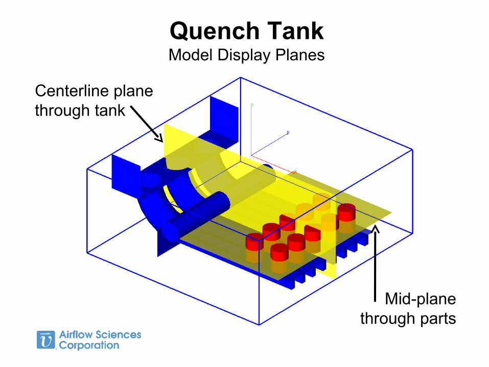
Quench TankModel Display Planes
Centerline planethrough tank
Mid-planethrough parts

Velocity DistributionBase Case
Deflector vanes create localized jets of flow
A portion of the flow bypasses the load entirely
Presence of support beams creates low velocity areas

Heat Transfer Coefficient Distribution
Base Case
“Shadows” from support beams create low heat transfer areas
Vanes cause front side of parts to have higher heat transfer than rear

Quench Tank GeometryOption 1 – Add Flow Baffles
Prevent flow bypass
Channel flow through load
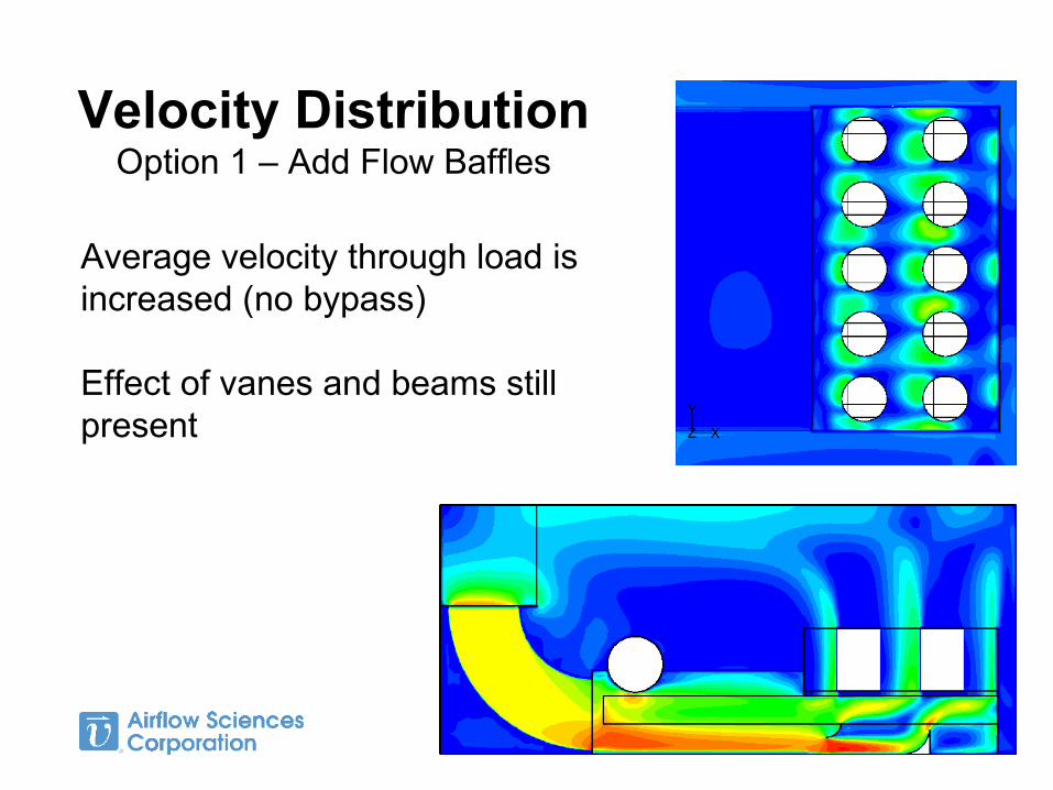
Velocity DistributionOption 1 – Add Flow Baffles
Average velocity through load is increased (no bypass)
Effect of vanes and beams still present

Heat Transfer Coefficient Distribution
Option 1 – Add Flow Baffles
Peak heat transfer rates are increased over base case
Pattern remains largely unchanged

How good can it get?
CFD allows for the exploration of idealized cases that are not necessarily practical
Quick and easy on the computer – difficult to try things out in hardware
Overall flow concept is to bring flow in from bottom
Try an idealized version of that concept to see if it works
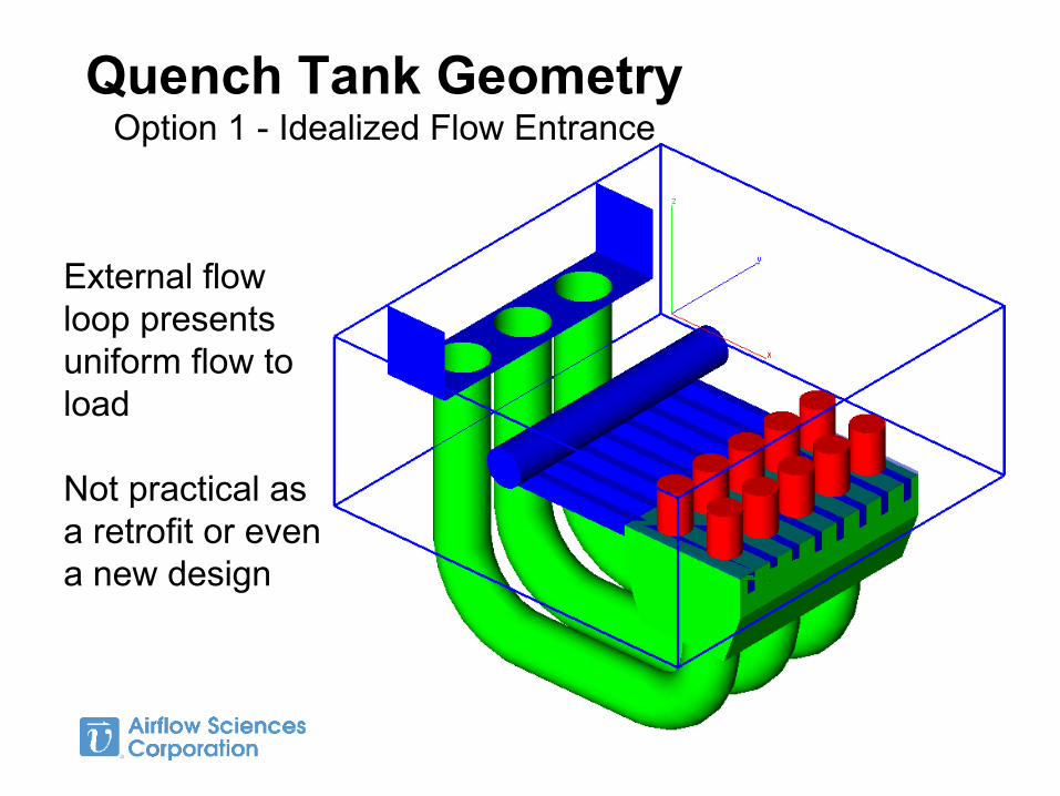
Quench Tank GeometryOption 1 - Idealized Flow Entrance
External flow loop presents uniform flow to load
Not practical as a retrofit or even a new design

Velocity DistributionOption 2 – Idealized Flow Entrance
Good front to back flow uniformity
Presence of support beams prevents better uniformity

Heat Transfer Coefficient DistributionOption 2 – Idealized
flow entrance
Lower overall heat transfer rates than baseline
Good front to back uniformity
Flow around beams creates high and low heat transfer zones

Quench Tank GeometryOption 3 – Revised Support Structure
Egg crateSupport structure
allows flow to pass1/2” web, 6” spacing, 12” tall
Flow baffles omitted for clarity
16% flow blockage compared to
32% for beams

Velocity DistributionOption 3 – Bottom Inlet, Egg-Crate
Support Structure
Very uniform flow throughout the load

Heat Transfer Coefficient Distribution
Option 3 – Bottom inlet,egg-crate support
structure
Lower overall heat transfer coefficient
Very good uniformity

Quench Tank GeometryOption 4 Design
Modified flow baffles channel flow beneath
support structure
“Ladder” vanes distribute and turn flow
up into the load

Ladder Vane Detail
Evenly spaced vanes along diagonal of 90 degree elbow evenly splits and turns flow
Requires even incoming flow

Velocity DistributionOption 4 – Final Design
Spacing of ladder vanes matches spacing of egg-crate support.
Good flow uniformity

Heat Transfer Coefficient Distribution
Option 4 - Final Design
Good part to part uniformity
Good front to back uniformity
Higher heat transfer coefficient on bottom than on top
Overall heat transfer coefficient slightly less than baseline

Comparison of Cases
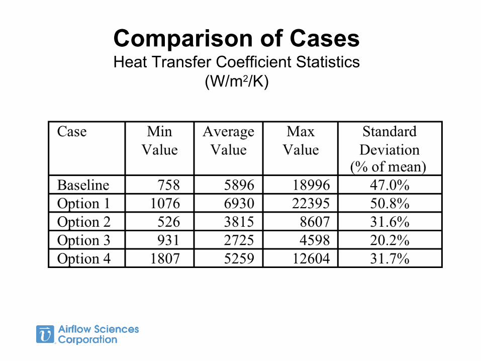
Comparison of CasesHeat Transfer Coefficient Statistics
(W/m2/K)

SummaryFour alternatives to initial quench tank design were investigated
Final design had:• 11% reduced overall heat transfer coefficient• 33% reduced variation in heat transfer coefficient
Baffles and flow control devices require 2.7 times as much pumping power (6 15.7 HP)
Overall quench rate could be increased by increasing quench flow rate
Modifications could be incorporated in existing quench tank

Questions?