quick guide vlt automationdrive fc 360 - 4006119988.com · making modern living possible quick...
TRANSCRIPT
MAKING MODERN LIVING POSSIBLE
Quick GuideVLT® AutomationDrive FC 360
vlt-drives.danfoss.com


Contents
1 Introduction 3
1.1 Purpose of the Manual 3
1.2 Additional Resources 3
1.3 Document and Software Version 3
1.4 Approvals and Certifications 3
1.5 Disposal 3
1.6 Product Overview 3
2 Safety 7
2.1 Safety Symbols 7
2.2 Qualified Personnel 7
2.3 Safety Precautions 7
3 Quick Start 9
3.1 Identification and Variants 9
3.2 Hand On/Auto On Mode 10
3.3 Application Selections 10
3.4 Jumper Terminal 12 and 27 14
3.5 Automatic Motor Adaptation (AMA) 14
4 Installation 15
4.1 Mechanical Installation 15
4.2 Electrical Installation 16
4.3 Serial Communication 22
5 Local Control Panel and Programming 23
5.1 Local Control Panel (LCP) Operations 23
5.2 Main Menu 25
5.3 Quick Menu 27
5.4 PM Motor Set-up 29
5.5 PROFIBUS 31
5.6 PROFINET 32
5.7 Parameter List 33
6 Application Examples 39
7 Diagnostics and Troubleshooting 43
7.1 Warning and Alarm Types 43
7.2 Warning and Alarm Displays 43
7.3 Warning and Alarm Code List 44
7.4 Error Code List 46
Contents Quick Guide
MG06A602 Danfoss A/S © 04/2015 All rights reserved. 1

7.5 Troubleshooting 46
8 Specifications 48
8.1 Mains Supply 3x380–480 V AC 48
8.2 General Technical Data 51
8.3 Fuses 55
8.4 Connection Tightening Torques 56
Index 57
Contents VLT® AutomationDrive FC 360
2 Danfoss A/S © 04/2015 All rights reserved. MG06A602
1 Introduction
1.1 Purpose of the Manual
The quick guide provides information for safe installationand commissioning of the frequency converter.
The quick guide is intended for use by qualified personnel.Read and follow the quick guide to use the frequencyconverter safely and professionally, and pay particularattention to the safety instructions and general warnings.Always keep this quick guide available with the frequencyconverter.VLT® is a registered trademark.
1.2 Additional Resources
Other resources are available to understand advancedfrequency converter functions and programming.
• The programming guide provides greater detail onworking with parameters.
• The design guide provides detailed capabilitiesand functionality to design motor controlsystems.
• Optional equipment is available that may changesome of the procedures described. Be sure to seethe instructions supplied with those options forspecific requirements.
Contact the local Danfoss supplier for technical documen-tations.
1.3 Document and Software Version
The quick guide is regularly reviewed and updated. Allsuggestions for improvement are welcome.
Edition Remarks Software version
MG06A6xx Replaces MG06A5xx 1.5x
1.4 Approvals and Certifications
Illustration 1.1 Approval
1.5 Disposal
Do not dispose of equipment containingelectrical components together withdomestic waste.Collect it separately in accordance withlocal and currently valid legislation.
1.6 Product Overview
A frequency converter is an electronic motor controllerthat converts AC mains input into a variable AC waveformoutput. The frequency and voltage of the output areregulated to control the motor speed or torque. Thefrequency converter can vary the speed of the motor inresponse to system feedback, such as changingtemperature or pressure for controlling fan, compressor, orpump motors. The frequency converter can also regulatethe motor by responding to remote commands fromexternal controllers.
In addition, the frequency converter monitors the systemand motor status, issues warnings or alarms for faultconditions, starts and stops the motor, optimises energyefficiency, and offers many more control, monitoring, andefficiency functions. Operation and monitoring functionsare available as status indications to an outside controlsystem or serial communication network.
Introduction Quick Guide
MG06A602 Danfoss A/S © 04/2015 All rights reserved. 3
1 1
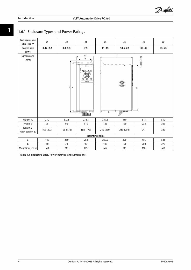
1.6.1 Enclosure Types and Power Ratings
Enclosure size380–480 V
J1 J2 J3 J4 J5 J6 J7
Power size[kW]
0.37–2.2 3.0–5.5 7.5 11–15 18.5–22 30–45 55–75
Dimensions[mm]
A a D
CBb
130B
C449
.10
Height A 210 272.5 272.5 317.5 410 515 550
Width B 75 90 115 133 150 233 308
Depth C(with option B)
168 (173) 168 (173) 168 (173) 245 (250) 245 (250) 241 323
Mounting holes
a 198 260 260 297.5 390 495 521
b 60 70 90 105 120 200 270
Mounting screw M4 M5 M5 M6 M6 M8 M8
Table 1.1 Enclosure Sizes, Power Ratings, and Dimensions
Introduction VLT® AutomationDrive FC 360
4 Danfoss A/S © 04/2015 All rights reserved. MG06A602
11

1.6.2 Exploded Views
130B
C439
.10
17
16
15
14
13
12
11
10
9
8
7
65
4
3
2
1
0302
01
0504
1 NLCP (accessory) 10 2-pole relay 2 (0.37–7.5 kW), pluggable3-pole relay 2 (11–22 kW), pluggable
2 Control cassette 11 Mains terminals
3 RFI switch (screw M3x12 only) 12 Cable strain relief (accessory for 0.37–2.2 kW units)
4 Removable fan assembly 13 Pluggable RS485 terminal
5 Grounding clamp (accessory) 14 Fixed I/O terminals
6 Screened cable grounding clamp and strain relief (accessory) 15 Fixed I/O terminals
7 Motor terminals (U, V, W), and brake and load sharing terminals 16 Terminal cover
8 PE ground 17 B options (MCB 102/MCB 103 accessories)
9 3-pole relay 1
Illustration 1.2 Exploded View, J1–J5 (0.37–22 kW), IP20
Introduction Quick Guide
MG06A602 Danfoss A/S © 04/2015 All rights reserved. 5
1 1
3
2
1
18
17
16 1514
13 12
11
10
9
8
7
6
5
4
130B
D64
7.10
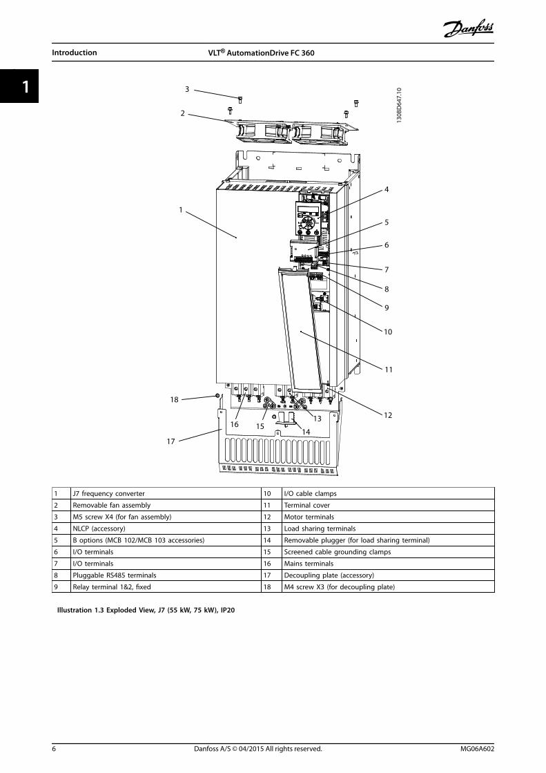
1 J7 frequency converter 10 I/O cable clamps
2 Removable fan assembly 11 Terminal cover
3 M5 screw X4 (for fan assembly) 12 Motor terminals
4 NLCP (accessory) 13 Load sharing terminals
5 B options (MCB 102/MCB 103 accessories) 14 Removable plugger (for load sharing terminal)
6 I/O terminals 15 Screened cable grounding clamps
7 I/O terminals 16 Mains terminals
8 Pluggable RS485 terminals 17 Decoupling plate (accessory)
9 Relay terminal 1&2, fixed 18 M4 screw X3 (for decoupling plate)
Illustration 1.3 Exploded View, J7 (55 kW, 75 kW), IP20
Introduction VLT® AutomationDrive FC 360
6 Danfoss A/S © 04/2015 All rights reserved. MG06A602
11
2 Safety
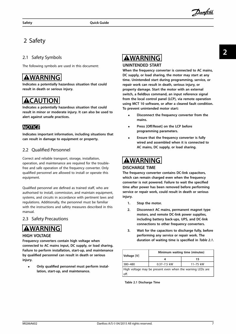
2.1 Safety Symbols
The following symbols are used in this document:
WARNINGIndicates a potentially hazardous situation that couldresult in death or serious injury.
CAUTIONIndicates a potentially hazardous situation that couldresult in minor or moderate injury. It can also be used toalert against unsafe practices.
NOTICEIndicates important information, including situations thatcan result in damage to equipment or property.
2.2 Qualified Personnel
Correct and reliable transport, storage, installation,operation, and maintenance are required for the trouble-free and safe operation of the frequency converter. Onlyqualified personnel are allowed to install or operate thisequipment.
Qualified personnel are defined as trained staff, who areauthorised to install, commission, and maintain equipment,systems, and circuits in accordance with pertinent laws andregulations. Additionally, the personnel must be familiarwith the instructions and safety measures described in thismanual.
2.3 Safety Precautions
WARNINGHIGH VOLTAGEFrequency converters contain high voltage whenconnected to AC mains input, DC supply, or load sharing.Failure to perform installation, start-up, and maintenanceby qualified personnel can result in death or seriousinjury.
• Only qualified personnel must perform instal-lation, start-up, and maintenance.
WARNINGUNINTENDED STARTWhen the frequency converter is connected to AC mains,DC supply, or load sharing, the motor may start at anytime. Unintended start during programming, service, orrepair work can result in death, serious injury, orproperty damage. Start the motor with an externalswitch, a fieldbus command, an input reference signalfrom the local control panel (LCP), via remote operationusing MCT 10 software, or after a cleared fault condition.To prevent unintended motor start:
• Disconnect the frequency converter from themains.
• Press [Off/Reset] on the LCP beforeprogramming parameters.
• Ensure that the frequency converter is fullywired and assembled when it is connected toAC mains, DC supply, or load sharing.
WARNINGDISCHARGE TIMEThe frequency converter contains DC-link capacitors,which can remain charged even when the frequencyconverter is not powered. Failure to wait the specifiedtime after power has been removed before performingservice or repair work, could result in death or seriousinjury.
1. Stop the motor.
2. Disconnect AC mains, permanent magnet typemotors, and remote DC-link power supplies,including battery back-ups, UPS, and DC-linkconnections to other frequency converters.
3. Wait for the capacitors to discharge fully, beforeperforming any service or repair work. Theduration of waiting time is specified in Table 2.1.
Voltage [V]Minimum waiting time (minutes)
4 15
380–480 0.37–7.5 kW 11–75 kW
High voltage may be present even when the warning LEDs areoff.
Table 2.1 Discharge Time
Safety Quick Guide
MG06A602 Danfoss A/S © 04/2015 All rights reserved. 7
2 2

WARNINGLEAKAGE CURRENT HAZARDLeakage currents exceed 3.5 mA. Failure to ground thefrequency converter properly can result in death orserious injury.
• Ensure the correct grounding of the equipmentby a certified electrical installer.
WARNINGEQUIPMENT HAZARDContact with rotating shafts and electrical equipmentcan result in death or serious injury.
• Ensure that only trained and qualified personnelperform installation, start-up, and maintenance.
• Ensure that electrical work conforms to nationaland local electrical codes.
• Follow the procedures in this manual.
NOTICEHIGH ALTITUDESFor installation at altitudes above 2000 m, contactDanfoss regarding PELV.
CAUTIONINTERNAL FAILURE HAZARDAn internal failure in the frequency converter can resultin serious injury, when the frequency converter is notproperly closed.
• Ensure that all safety covers are in place andsecurely fastened before applying power.
NOTICEUse on Isolated MainsFor details about the use of the frequency converter onisolated mains, refer to section RFI Switch in the designguide.Follow the recommendations regarding the installationon IT-mains. Use relevant monitoring devices for IT-mainsto avoid damage.
Safety VLT® AutomationDrive FC 360
8 Danfoss A/S © 04/2015 All rights reserved. MG06A602
22

3 Quick Start
WARNINGImproper use could result in death, serious injury,equipment, or property damage. Before installing orusing the equipment, carefully read chapter 2 Safety andchapter 4 Installation.
3.1 Identification and Variants
Confirm that the equipment matches the requirements andordering information by checking power size, voltage data,and overload data on the nameplate of the frequencyconverter.
130B
C435
.11
CHASSIS/IP20
VLT
MADE BY DANFOSS IN CHINA
AutomationDrivewww.danfoss.com
R
T/C: FC-360HK37T4E20H2BXCDXXSXXXXAXBXP/N: 134F2970 S/N: 691950A2400.37 kW 0.5HP High OverloadIN: 3x380-480V 50/60Hz 1.24/0.99A
OUT: 3x0-Vin 0-500Hz 1.2/1.1A(Tamb. 45 C)o
1
2
3
CAUTION:SEE MANUAL
WARNING:
AND LAODSHARING BEFORE SERVICE
STORED CHARGE DO NOT TOUCH UNTIL 4 MIN. AFTER DISCONNECTIONRISK OF ELECTRIC SHOCK-DUAL SUPPLY DISCONNECT MAINS
1 Type code
2 Ordering number
3 Specifications
Illustration 3.1 Nameplate 1 and 2
1–6: Product Name
7: OverloadH: Heavy duty
Q: Normal duty1)
8–10: Power size
0.37–75 kW. For example:
K37: 0.37 kW2)
1K1: 1.1 kW11K: 11 kW
11–12: Voltage class T4: 380–480 V 3-phases
13–15: IP class E20: IP20
16–17: RFI H2: C3 Class
18: Brake chopperX: No
B: Built-in3)
19: LCP X: No
20: PCB coating C: 3C3
21: Mains terminals D: Load sharing
29–30: Embeddedfieldbus
AX: NoA0: PROFIBUSAL: PROFINET
Table 3.1 Type Code: Selection of Different Features and Options
For options and accessories, refer to the section Options andAccessories in the FC 360 Design Guide.1) Only 11–75 kW for normal duty variants. PROFIBUS and PROFINETunavailable for normal duty.2) For all power sizes, see chapter 8.1.1 Mains Supply 3x380–480 VAC.3) 0.37–22 kW with built-in brake chopper. 30–75 kW with externalbrake chopper only.
130B
C437
.10
1 2 3 4 5 6 7 8 9 10 11 12 13 14 15 16 17 18 19 20 21 22 23 24 25 26 27 28 29 30 31 32
F C - 3 6 0 H T 4 E 2 0 H 2 X X C D X X S X X X X A X B X
Q B 0
L
A
A
Illustration 3.2 Type Code String
Quick Start Quick Guide
MG06A602 Danfoss A/S © 04/2015 All rights reserved. 9
3 3

3.2 Hand On/Auto On Mode
After installation (see chapter 4 Installation), there are 2simple ways to start up the frequency converter: Hand Onand Auto On mode. At the first power-up, it is in Auto Onmode.
130B
D06
2.10
D HandOn Reset
AutoOn
OKOn
Warn
Alarm
Illustration 3.3 Location of Hand On, Off/Reset and Auto OnKeys on the NLCP
• Press [Hand On] to provide a local start commandto the frequency converter. Press [] and [] toincrease and decrease speed.
• Press [Off/Reset] to stop the frequency converter.
• Press [Auto On] to control the frequencyconverter either via control terminals or serialcommunication.
CAUTIONSince the frequency converter is in Auto On mode at firstpower-up, the frequency converter may start the motordirectly.
NOTICEParameter 5-12 Terminal 27 Digital Input has coast inverseas default setting. Connect terminals 12 and 27 to testHand On/Auto On running.
For LCP operation, see chapter 5 Local Control Panel andProgramming.
3.3 Application Selections
Use the selections for quick application set-up of the mostcommon applications by setting parameter 0-16 ApplicationSelection. When necessary, the selections can be modifiedfor individual needs. All selections are for Auto On mode.
NOTICEWhen an application is selected, relevant parameters areautomatically set. Customer-specific configuration of allparameters based on specific requirements is stillpossible.
NOTICEIf any of the applications are selected, relay 1 is set to[Running] and relay 2 is set to [Alarm]
ApplicationPumps, fans, compressors
DescriptionFor applications where a value (for example, pressure,temperature) must be kept at a desired level by sensor feedback
130B
C43
0.10
+24V 12
DI1 18
DI2 19
DI3 27
DI4 29
DI5 32
DI6 33
DI7 31
COM 20
+10V 50
AI1 53 - +
AI2 54
COM 55
AO1 45
AO2 42
1
2
3
4
5
6
R1
R2
FC 360
Start
Coast inverse
Jog
4-20mA
Parameter settings
Parameter Option/value
Parameter 1-00 Configuration Mode [3] Process ClosedLoop
Parameter 1-03 Torque Characteristics [1] Variable Torque
Parameter 3-00 Reference Range [0] Min- Max
Parameter 3-15 Reference 1 Source [0] No Function
Parameter 4-12 Motor Speed Low Limit [Hz] 30.0 Hz
Parameter 4-14 Motor Speed High Limit[Hz]
50.0 Hz
Parameter 5-10 Terminal 18 Digital Input [8] Start
Parameter 5-12 Terminal 27 Digital Input [2] Coast Inverse
Parameter 5-14 Terminal 32 Digital Input [14] Jog
Parameter 5-40 Function Relay(Relay 1 Selection)
[5] Running
Parameter 5-40 Function Relay(Relay 2 Selection)
[9] Alarm
Parameter 6-22 Terminal 54 Low Current 4.0 mA
Parameter 6-23 Terminal 54 High Current 20.0 mA
Parameter 6-29 Terminal 54 mode [0] Current Mode
Parameter 6-70 Terminal 45 Mode [0] 0–20 mA
Quick Start VLT® AutomationDrive FC 360
10 Danfoss A/S © 04/2015 All rights reserved. MG06A602
33

Parameter 6-71 Terminal 45 Analog Output [100] Outputfrequency
Parameter 6-90 Terminal 42 Mode [0] 0–20 mA
Parameter 6-91 Terminal 42 Analog Output [103] Motor Current
Parameter 7-20 Process CL Feedback 1Resource
[2] Analog input 54
Table 3.2 Process Closed Loop
ApplicationLocal/remote
DescriptionFor applications where the speed reference can be switchedbetween local potentiometer and remote current signal
130B
C43
1.10
+24V 12
DI1 18
DI2 19
DI3 27
DI4 29
DI5 32
DI6 33
DI7 31
COM 20
+10V 50
AI1 53
- +AI2 54
COM 55
AO1 45
AO2 42
1
2
3
4
5
6
R1
R2
FC 360
Start
Coast inverse
Setup select
4-20mA
Parameter settings Set-up 1 Set-up 2
Parameter 0-10 Active Set-up
[9] Multi Set-up [9] Multi Set-up
Parameter 0-12 Link Setups [20] Linked [20] Linked
Parameter 1-00 Configu-ration Mode
[0] Speed Open Loop [0] Speed OpenLoop
Parameter 3-00 ReferenceRange
[0] Min–Max [0] Min–Max
Parameter 3-15 Reference 1Source
[1] AI 53 [2] AI 54
Parameter 3-16 Reference 2Source
Parameter 4-12 MotorSpeed Low Limit [Hz]
25.0 Hz 25.0 Hz
Parameter 4-14 MotorSpeed High Limit [Hz]
50.0 Hz 50.0 Hz
Parameter 5-10 Terminal 18Digital Input
[8] Start [8] Start
Parameter 5-12 Terminal 27Digital Input
[2] Coast Inverse [2] CoastInverse
Parameter 5-14 Terminal 32Digital Input
[23] Set-up select [23] Set-upselect
Parameter 5-40 FunctionRelay (Relay 1 Selection)
[5] Running [5] Running
Parameter 5-40 FunctionRelay (Relay 2 Selection)
[9] Alarm [9] Alarm
Parameter 6-10 Terminal 53Low Voltage
0.07 V
Parameter 6-11 Terminal 53High Voltage
10 V
Parameter 6-19 Terminal 53mode
[1] Voltage Mode
Parameter 6-22 Terminal 54Low Current
4.0 mA
Parameter 6-23 Terminal 54High Current
20.0 mA
Parameter 6-29 Terminal 54mode
[0] CurrentMode
Parameter 6-70 Terminal 45Mode
[0] 0–20 mA [0] 0–20 mA
Parameter 6-71 Terminal 45Analog Output
[100] Outputfrequency
[100] Outputfrequency
Parameter 6-90 Terminal 42Mode
[0] 0–20 mA [0] 0–20 mA
Parameter 6-91 Terminal 42Analog Output
[103] Motor Current [103] MotorCurrent
Table 3.3 Local/Remote
Quick Start Quick Guide
MG06A602 Danfoss A/S © 04/2015 All rights reserved. 11
3 3

ApplicationConveyors, extruders
DescriptionFor running at a stable speed by a voltage reference signal.
130B
C43
2.10
+24V 12
DI1 18
DI2 19
DI3 27
DI4 29
DI5 32
DI6 33
DI7 31
COM 20
+10V 50
AI1 53
AI2 54
COM 55
AO1 45
AO2 42
1
2
3
4
5
6
R1
R2
FC 360
Start
Coast inverse
Parameter settings
Parameter Option/value
Parameter 1-00 Configuration Mode [0] Speed Open Loop
Parameter 3-00 Reference Range [0] Min–Max
Parameter 3-15 Reference 1 Source [1] AI 53
Parameter 4-12 Motor Speed Low Limit[Hz]
25.0 Hz
Parameter 4-14 Motor Speed High Limit[Hz]
50.0 Hz
Parameter 5-10 Terminal 18 Digital Input [8] Start
Parameter 5-12 Terminal 27 Digital Input [2] Coast Inverse
Parameter 5-40 Function Relay (Relay 1Selection)
[5] Running
Parameter 5-40 Function Relay (Relay 2Selection)
[9] Alarm
Parameter 6-10 Terminal 53 Low Voltage 0.07 V
Parameter 6-11 Terminal 53 High Voltage 10 V
Parameter 6-19 Terminal 53 mode [1] Voltage Mode
Parameter 6-70 Terminal 45 Mode [0] 0–20 mA
Parameter 6-71 Terminal 45 AnalogOutput
[100] Output frequency
Parameter 6-90 Terminal 42 Mode [0] 0–20 mA
Parameter 6-91 Terminal 42 AnalogOutput
[103] Motor Current
Table 3.4 Speed Open Loop
ApplicationMachine tools, texturizers
DescriptionFor precise speed applications with 24 V encoder feedback
130B
C433
.12
+24 V 12
DI1 18
DI2 19
DI3 27
DI4 29
DI5 32
DI6 33
DI7 31
COM 20
50
AI1 53
AI2 54
COM 55
AO1 45
AO2 42
1
2
3
4
5
6
R1
R2
FC 360
Start
Coast inverse
+10 V
B
A
Parameter settings
Parameter Option/value
Parameter 1-00 Configuration Mode [1] Speed Close Loop
Parameter 3-00 Reference Range [0] Min–Max
Parameter 3-15 Reference 1 Source [1] AI 53
Parameter 3-16 Reference 2 Source [11] Local Bus Ref
Parameter 4-12 Motor Speed Low Limit[Hz]
20.0 Hz
Parameter 4-14 Motor Speed High Limit[Hz]
50.0 Hz
Parameter 5-10 Terminal 18 Digital Input [8] Start
Parameter 5-12 Terminal 27 Digital Input [2] Coast Inverse
Parameter 5-14 Terminal 32 Digital Input [82] Encoder input B
Parameter 5-15 Terminal 33 Digital Input [81] Encoder input A
Parameter 5-40 Function Relay (Relay 1Selection)
[5] Running
Parameter 5-40 Function Relay (Relay 2Selection)
[9] Alarm
Parameter 6-10 Terminal 53 Low Voltage 0.07 V
Parameter 6-11 Terminal 53 High Voltage 10 V
Parameter 6-19 Terminal 53 mode [1] Voltage Mode
Parameter 6-70 Terminal 45 Mode [0] 0–20 mA
Parameter 6-71 Terminal 45 AnalogOutput
[100] Output frequency
Parameter 6-90 Terminal 42 Mode [0] 0–20 mA
Parameter 6-91 Terminal 42 AnalogOutput
[103] Motor Current
Quick Start VLT® AutomationDrive FC 360
12 Danfoss A/S © 04/2015 All rights reserved. MG06A602
33

Parameter 7-00 Speed PID FeedbackSource
[1] 24 V encoder
Table 3.5 Speed Close Loop
ApplicationIndustrial washing machines, conveyors
DescriptionFor applications with 8 different speeds by digital input. By usinganother digital input, 16 speeds are possible.
130B
C43
4.10
+24V 12
DI1 18
DI2 19
DI3 27
DI4 29
DI5 32
DI6 33
DI7 31
COM 20
+10V 50
AI1 53
AI2 54
COM 55
AO1 45
AO2 42
1
2
3
4
5
6
R1
R2
FC 360
Start
Coast inverse
Pre set ref bit 0
Pre set ref bit 1
Pre set ref bit 2
Parameter settings
Parameter Option/value
Parameter 1-00 Configuration Mode [0] Speed Open Loop
Parameter 3-00 Reference Range [0] Min–Max
Parameter 3-15 Reference 1 Source [0] No Function
Parameter 4-14 Motor Speed High Limit[Hz]
50.0 Hz
Parameter 5-10 Terminal 18 Digital Input [8] Start
Parameter 5-12 Terminal 27 Digital Input [2] Coast Inverse
Parameter 5-13 Terminal 29 Digital Input [16] Preset ref bit 0
Parameter 5-14 Terminal 32 Digital Input [17] Preset ref bit 1
Parameter 5-15 Terminal 33 Digital Input [18] Preset ref bit 2
Parameter 6-70 Terminal 45 Mode [0] 0–20 mA
Parameter 6-71 Terminal 45 AnalogOutput
[100] Output frequency
Parameter 6-90 Terminal 42 Mode [0] 0–20 mA
Parameter 6-91 Terminal 42 AnalogOutput
[103] Motor Current
Table 3.6 Multi-speed
ApplicationOne Gear Drive (OGD)
DescriptionFor applications that use OGD. For example, conveyors in foodand beverage industries.
+24V 12
DI1 18
DI2 19
DI3 27
DI4 29
DI5 32
DI6 33
DI7 31
COM 20
+10V 50
AI1 53 - +AI2 54
COM 55
AO1 45
AO2 42
1
2
3
4
5
6
R1
R2
FC 360
Start
Coast inverse
4-20mA
130B
D89
8.10
Parameter settings
Parameter Option/value
Parameter 1-00 Configuration Mode [0] Open Loop
Parameter 1-01 Motor Control Principle [1] VVC+
Parameter 1-08 Motor Control Bandwidth high
Parameter 1-10 Motor Construction [1] PM, non-salient SPM
Parameter 1-14 Damping Gain 120
Parameter 1-15 Low Speed Filter TimeConst.
0.175
Parameter 1-16 High Speed Filter TimeConst.
0.175
Parameter 1-17 Voltage filter time const. 0.035
Parameter 1-24 Motor Current 7.2
Parameter 1-25 Motor Nominal Speed 3000
Parameter 1-26 Motor Cont. Rated Torque 12.6
Parameter 1-29 Automatic MotorAdaptation (AMA)
[0] Off
Parameter 1-30 Stator Resistance (Rs) 0.5
Parameter 1-37 d-axis Inductance (Ld) 5
Parameter 1-39 Motor Poles 10
Parameter 1-40 Back EMF at 1000 RPM 120
Parameter 1-42 Motor Cable Length 50 m
Parameter 1-66 Min. Current at Low Speed 50
Parameter 1-73 Flying Start [2] Enable always
Parameter 2-06 Parking Current 80
Parameter 2-07 Parking Time 0.5
Quick Start Quick Guide
MG06A602 Danfoss A/S © 04/2015 All rights reserved. 13
3 3

Parameter 2-10 Brake Function [0] Off
Parameter 3-03 Maximum Reference 250 Hz
Parameter 4-14 Motor Speed High Limit[Hz]
250 Hz
Parameter 4-16 Torque Limit Motor Mode 160
Parameter 4-18 Current Limit 160
Parameter 5-10 Terminal 18 Digital Input [8] Start
Parameter 5-11 Terminal 19 Digital Input [0] No operation
Parameter 5-12 Terminal 27 Digital Input [2] Coast inverse
Parameter 5-13 Terminal 29 Digital Input [0] No operation
Parameter 5-14 Terminal 32 Digital Input [0] No operation
Parameter 5-15 Terminal 33 Digital Input [0] No operation
Parameter 5-16 Terminal 31 Digital Input [0] No operation
Parameter 6-10 Terminal 53 Low Voltage 4.0 mA
Parameter 6-11 Terminal 53 High Voltage 20.0 mA
Parameter 6-14 Terminal 53 Low Ref./Feedb. Value
0
Parameter 6-15 Terminal 53 High Ref./Feedb. Value
250
Parameter 6-19 Terminal 53 mode [0] Current Mode
Parameter 14-01 Switching Frequency 10.0 kHz
Parameter 14-07 Dead Time Compen-sation Level
65
Parameter 14-64 Dead Time Compen-sation Zero Current Level
[0] Disabled
Parameter 14-65 Speed Derate Dead TimeCompensation
250
Parameter 14-51 DC-Link Voltage Compen-sation
[0] Off
Parameter 30-20 High Starting TorqueTime [s]
0
Parameter 30-21 High Starting TorqueCurrent [%]
100
Parameter 30-22 Locked Rotor Protection [0] Off
Parameter 30-23 Locked Rotor DetectionTime [s]
1
Table 3.7 One Gear Drive (OGD)
For further examples, refer to chapter 6 ApplicationExamples.
3.4 Jumper Terminal 12 and 27
When the factory default programming values are used,connect a jumper wire between terminal 12 and terminal27 for the frequency converter to operate.
• Digital input terminal 27 is designed to receive a24 V DC external interlock command. In manyapplications, wire an external interlock device toterminal 27.
• When no interlock device is used, wire a jumperbetween control terminal 12 and terminal 27. Thisprovides internal 24 V signal on terminal 27.
• No signal present prevents the unit fromoperating.
3.5 Automatic Motor Adaptation (AMA)
Automatic motor adaptation (AMA)It is highly recommended to run AMA because it measuresthe electrical characteristics of the motor to optimisecompatibility between the frequency converter and themotor under VVC+ mode.
• The frequency converter builds a mathematicalmodel of the motor for regulating output motorcurrent, thus enhancing motor performance.
• Some motors are unable to run the completeversion of the test. In that case, select Enablereduced AMA.
• If warnings or alarms occur, seechapter 7.3 Warning and Alarm Code List.
• Run this procedure on a cold motor for bestresults.
To run AMA using the numeric LCP1. By default parameter setting, connect terminals
12 and 27 before running AMA.
2. Enter the Main Menu.
3. Go to parameter group 1-** Load and Motor.
4. Press [OK].
5. Set motor parameters using nameplate data forparameter group 1-2* Motor Data.
6. Set motor cable length in parameter 1-42 MotorCable Length
7. Go to parameter 1-29 Automatic Motor Adaptation(AMA).
8. Press [OK].
9. Select [1] Enable complete AMA.
10. Press [OK].
11. The test runs automatically and indicates when itis complete.
Depending on the power size, the AMA takes 3–10minutes to complete.
NOTICEThe AMA function in FC 360 does not cause the motor torun, and it does not harm the motor.
Quick Start VLT® AutomationDrive FC 360
14 Danfoss A/S © 04/2015 All rights reserved. MG06A602
33

4 Installation
4.1 Mechanical Installation
Select the best possible operation site by considering:• Ambient operating temperature.
• Installation method.
• Cooling.
• Position of the frequency converter.
• Cable routing.
• Power source supplying correct voltage andnecessary current.
• Motor current rating within the maximum currentfrom the frequency converter.
• Correct rating of external fuses and circuitbreakers.
Cooling and Mounting:• Provide top and bottom clearance for air cooling,
see Table 4.1 for clearance requirements.
• Consider derating for temperatures starting from45 °C and elevation 1000 m above sea level. Seethe design guide for details on derating.
Enclosure size J1–J5 J6 and J7
Clearance above and below theunit [mm]
100 200
Table 4.1 Minimum Airflow Clearance Requirements
• Mount the unit vertically.
• IP20 units allow side-by-side installation.
• Improper mounting can result in overheating andreduced performance.
• Use the slotted mounting holes on the unit forwall mounting, when provided.
• See chapter 8.4 Connection Tightening Torques forproper tightening specifications.
Installation Quick Guide
MG06A602 Danfoss A/S © 04/2015 All rights reserved. 15
4 4

4.2 Electrical Installation
This section describes how to wire the frequency converter.
130B
C438
.15
3 Phasepowerinput
Switch ModePower Supply
Motor
Analog Output
Interface
(PNP) = Source (NPN) = Sink
ON=TerminatedOFF=Open
Brakeresistor
91 (L1)92 (L2)93 (L3)
PE
50 (+10 V OUT)
53 (A IN)
54 (A IN)
55 (COM A IN)
0/4-20 mA
12 (+24 V OUT)
31 (D IN)
18 (D IN)
20 (COM D IN)
10 V DC15 mA 100 mA
+ - + -
(U) 96(V) 97
(W) 98(PE) 99
(A OUT) 45
(A OUT) 42
(P RS-485) 68
(N RS-485) 69
(COM RS-485) 61
0V
5V
S801
0/4-20 mA
RS-485RS-485
03
+10 V DC
0/4-20 mA0-10 V DC
24 V DC
02
01
05
04
240 V AC, 3 A
24 V (NPN) 0 V (PNP)
0 V (PNP)24 V (NPN)
19 (D IN)
24 V (NPN) 0 V (PNP)27 (D IN/OUT)
24 V
0 V
0 V (PNP)24 V (NPN)
0 V
24 V29 (D IN/OUT)
24 V (NPN) 0 V (PNP)
0 V (PNP)24 V (NPN)
33 (D IN)
32 (D IN)
95
P 5-00
21 O
N
(+UDC) 89
(BR) 81 5)
24 V (NPN) 0 V (PNP)
0-10 V DC
(-UDC) 88
RFI
3)
0 V
240 V AC, 3 A
Relay 1
1)
Relay 2 2)
4)
06
Illustration 4.1 Basic Wiring Schematic Drawing
A=Analog, D=Digital1) Built-in brake chopper available from 0.37–22 kW.2) Relay 2 is 2-pole for J1–J3 and 3-pole for J4–J7. Relay 2 of J4–J7 with terminals 4, 5, and 6 has the same NO/NC logic as relay1. Relays are pluggable in J1–J5, and fixed in J6–J7.3) Single DC choke in 0.37–22 kW (J1–J5); Dual DC choke in 30–75 kW (J6–J7).4) Switch S801 (bus terminal) can be used to enable termination on the RS485 port (terminals 68 and 69).5) No BR for 30–75 kW (J6–J7).
Installation VLT® AutomationDrive FC 360
16 Danfoss A/S © 04/2015 All rights reserved. MG06A602
44

130B
D39
1.11
1
23
4
5
6
78
9 10
ResetAuto
OnHand
On
OK
Back
Menu
Status QuickMenu
MainMenu
PE
UVW
L1L2L3PE
1 PLC 6 Minimum 200 mm (7.9 inch) between control cables, motor, andmains
2 Frequency converter 7 Motor, 3-phase and PE
3 Output contactor (not recommended) 8 Mains, 3-phase and reinforced PE
4 Grounding rail (PE) 9 Control wiring
5 Cable shielding (stripped) 10 Equalising minimum 16 mm2 (6 AWG)
Illustration 4.2 Typical Electrical Connection
Installation Quick Guide
MG06A602 Danfoss A/S © 04/2015 All rights reserved. 17
4 4

4.2.1 General Requirements
WARNINGEQUIPMENT HAZARD!Rotating shafts and electrical equipment can behazardous. It is important to protect against electricalhazards when applying power to the unit. All electricalwork must conform to national and local electrical codes.Installation, start up, and maintenance must beperformed only by trained and qualified personnel.Failure to follow these guidelines could result in death orserious injury.
CAUTIONWIRING ISOLATION!Run input power, motor wiring, and control wiring in 3separate metallic conduits or use separated screenedcable for high frequency noise isolation. Failure to isolatepower, motor, and control wiring could result in less thanoptimum frequency converter and associated equipmentperformance.Run motor cables from multiple frequency convertersseparately. Induced voltage from output motor cablesrun together can charge equipment capacitors even withthe equipment turned off and locked out.
• An electronically activated function within thefrequency converter provides overload protectionfor the motor. The overload provides Class 20motor overload protection.
Wire type and ratings
• All wiring must comply with local and nationalregulations regarding cross-section and ambienttemperature requirements.
• Danfoss recommends that all power connectionsbe made with a minimum 75 °C rated copperwire.
• See chapter 8 Specifications for recommendedwire sizes.
4.2.2 Grounding Requirements
WARNINGGROUNDING HAZARD!For operator safety, a certified electrical installer shouldground the frequency converter in accordance withnational and local electrical codes as well as instructionscontained within this manual. Ground currents are higherthan 3.5 mA. Failure to ground the frequency converterproperly could result in death or serious injury.
• Establish proper protective grounding forequipment with ground currents higher than 3.5mA must be established.
• A dedicated ground wire is required for inputpower, motor power, and control wiring.
• Use the clamps provided with the equipment forproper ground connections.
• Do not ground 1 frequency converter to anotherin a daisy chain fashion (see Illustration 4.3).
• Keep the ground wire connections as short aspossible.
• Use high-strand wire to reduce electrical noise.
• Follow motor manufacturer wiring requirements.
130B
C500
.10
FC 1
FC 1
FC 2
FC 2
FC 3
FC 3
PE
PE
Illustration 4.3 Grounding Principle
4.2.3 Mains, Motor, and GroundConnections
WARNINGINDUCED VOLTAGE!Run output motor cables from multiple frequencyconverters separately. Induced voltage from outputmotor cables run together can charge equipmentcapacitors even when the equipment is turned off andlocked out. Failure to run output motor cables separatelycould result in death or serious injury.
Grounding clamps are provided for motor wiring (seeIllustration 4.4).
Installation VLT® AutomationDrive FC 360
18 Danfoss A/S © 04/2015 All rights reserved. MG06A602
44
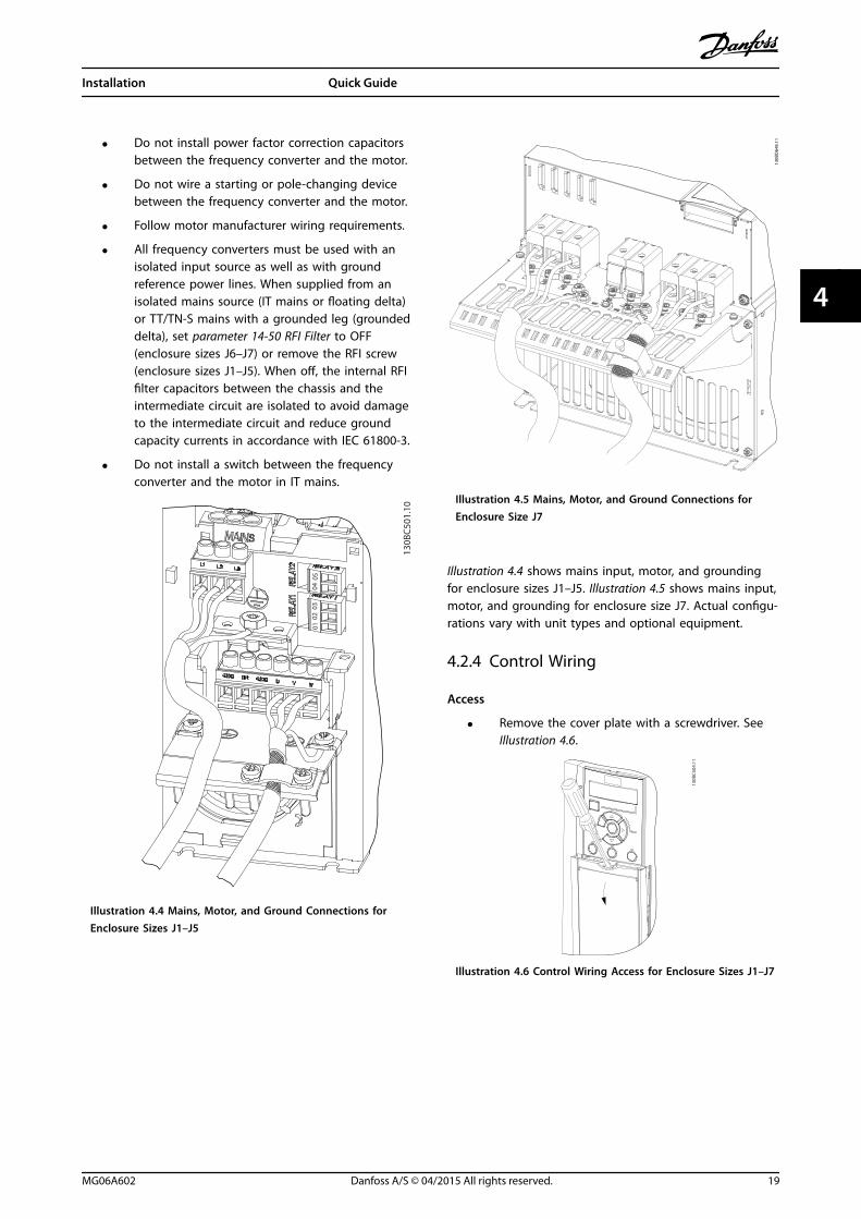
• Do not install power factor correction capacitorsbetween the frequency converter and the motor.
• Do not wire a starting or pole-changing devicebetween the frequency converter and the motor.
• Follow motor manufacturer wiring requirements.
• All frequency converters must be used with anisolated input source as well as with groundreference power lines. When supplied from anisolated mains source (IT mains or floating delta)or TT/TN-S mains with a grounded leg (groundeddelta), set parameter 14-50 RFI Filter to OFF(enclosure sizes J6–J7) or remove the RFI screw(enclosure sizes J1–J5). When off, the internal RFIfilter capacitors between the chassis and theintermediate circuit are isolated to avoid damageto the intermediate circuit and reduce groundcapacity currents in accordance with IEC 61800-3.
• Do not install a switch between the frequencyconverter and the motor in IT mains.
130B
C501
.10
0102
0304
05
Illustration 4.4 Mains, Motor, and Ground Connections forEnclosure Sizes J1–J5
130B
D64
8.11
Illustration 4.5 Mains, Motor, and Ground Connections forEnclosure Size J7
Illustration 4.4 shows mains input, motor, and groundingfor enclosure sizes J1–J5. Illustration 4.5 shows mains input,motor, and grounding for enclosure size J7. Actual configu-rations vary with unit types and optional equipment.
4.2.4 Control Wiring
Access
• Remove the cover plate with a screwdriver. SeeIllustration 4.6.
130B
C504
.11
Illustration 4.6 Control Wiring Access for Enclosure Sizes J1–J7
Installation Quick Guide
MG06A602 Danfoss A/S © 04/2015 All rights reserved. 19
4 4

Control Terminal TypesIllustration 4.7 shows the frequency converter controlterminals. Terminal functions and default settings aresummarised in Table 4.2.
42 45
12 18 19 27 29 31 32 33 20 50 53 54 55
130B
C505
.12
Illustration 4.7 Control Terminal Locations
See chapter 8.2 General Technical Data for terminal ratingsdetails.
Terminal ParameterDefaultsetting
Description
Digital I/O, pulse I/O, encoder
12 – +24 V DC
24 V DC supplyvoltage.Maximumoutput current is100 mA for all24 V loads.
18Parameter 5-10 Ter
minal 18 DigitalInput
[8] Start
Digital inputs.
19Parameter 5-11 Ter
minal 19 DigitalInput
[10]Reversing
31Parameter 5-16 Ter
minal 31 DigitalInput
[0] Nooperation
Digital input
32parameter 5-14 Ter
minal 32 DigitalInput
[0] Nooperation
Digital input, 24V encoder.Terminal 33 canbe used forpulse input.33
Parameter 5-15 Terminal 33 Digital
Input
[0] Nooperation
Terminal ParameterDefaultsetting
Description
27
Parameter 5-12 Terminal 27 Digital
Inputparameter 5-30 Ter
minal 27 DigitalOutput
DI [2] CoastinverseDO [0] Nooperation
Selectable foreither digitalinput, digitaloutput, or pulseoutput. Defaultsetting is digitalinput.Terminal 29 canbe used forpulse input.
29
Parameter 5-13 Terminal 29 Digital
Inputparameter 5-31 Ter
minal 29 DigitalOutput
DI [14] JogDO [0] Nooperation
20 –
Common fordigital inputsand 0 Vpotential for 24V supply.
Analog inputs/outputs
42Parameter 6-91 Ter
minal 42 AnalogOutput
[0] Nooperation
Programmableanalog output.The analogsignal is 0–20mA or 4–20 mAat a maximum of
500 Ω. Can alsobe configured asdigital outputs
45Parameter 6-71 Ter
minal 45 AnalogOutput
[0] Nooperation
50 – +10 V DC
10 V DC analogsupply voltage.15 mA maximumcommonly usedfor potenti-ometer orthermistor.
536-1* parameter
groupReference Analog input.
Selectable forvoltage orcurrent.54
6-2* parametergroup
Feedback
55 –
Common foranalog input
Serial communication
61 –
Integrated RC-filter for cablescreen. ONLY forconnecting thescreen whenexperiencingEMC problems.
Installation VLT® AutomationDrive FC 360
20 Danfoss A/S © 04/2015 All rights reserved. MG06A602
44

Terminal ParameterDefaultsetting
Description
68 (+)8-3* parameter
group
RS485 interface.A control cardswitch isprovided forterminationresistance.
69 (-)8-3* parameter
group
Relays
01, 02, 03 5-40 [0][0] Nooperation
Form C relayoutput. Theserelays are invarious locationsdepending uponthe frequencyconverter config-uration and size.Usable for AC orDC voltage andresistive orinductive loads.RO2 in J1–J3enclosure is 2-pole, onlyterminals 04 and05 are available
04, 05, 06 5-40 [1][0] Nooperation
Table 4.2 Terminal Descriptions
Control terminal functionsFrequency converter functions are commanded byreceiving control input signals.
• Programme each terminal for the function itsupports in the parameters associated with thatterminal.
• Confirm that the control terminal is programmedfor the correct function. See chapter 5 LocalControl Panel and Programming for details onaccessing parameters and programming.
• The default terminal programming initiatesfrequency converter functioning in a typicaloperational mode.
Using screened control cablesThe preferred method in most cases is to secure controland serial communication cables with screening clampsprovided at both ends to ensure the best possible highfrequency cable contact.If the ground potential between the frequency converterand the PLC is different, electric noise could disturb theentire system. Solve this problem by fitting an equalisingcable as close as possible to the control cable. Minimumcable cross-section: 16 mm2 (6 AWG).
12
PE
FC
PE
PLC
130B
B922
.12
PE PE<10 mm
1 Minimum 16 mm2 (6 AWG)
2 Equalising cable
Illustration 4.8 Screening Clamps at Both Ends
50/60 Hz ground loopsWith long control cables, ground loops could occur. Toeliminate ground loops, connect 1 end of the screen-to-ground with a 100 nF capacitor (keeping leads short).
100nF
FC
PEPE
PLC
<10 mm 130B
B609
.12
Illustration 4.9 Connection with a 100 nF Capacitor
Avoid EMC noise on serial communicationThis terminal is connected to ground via an internal RClink. Use twisted-pair cables to reduce interferencebetween conductors. The recommended method is shownin Illustration 4.10.
PE
FC
PE
FC
130B
B923
.12
PE PE
696861
696861
12
<10 mm
1 Minimum 16 mm2 (6 AWG)
2 Equalising cable
Illustration 4.10 Twisted-pair Cables
Alternatively, the connection to terminal 61 can beomitted.
PE
FC
PE
FC
130B
B924
.12
PE PE
69696868
12
<10 mm
1 Minimum 16 mm2 (6 AWG)
2 Equalising cable
Illustration 4.11 Twisted-pair Cables without Terminal 61
Installation Quick Guide
MG06A602 Danfoss A/S © 04/2015 All rights reserved. 21
4 4
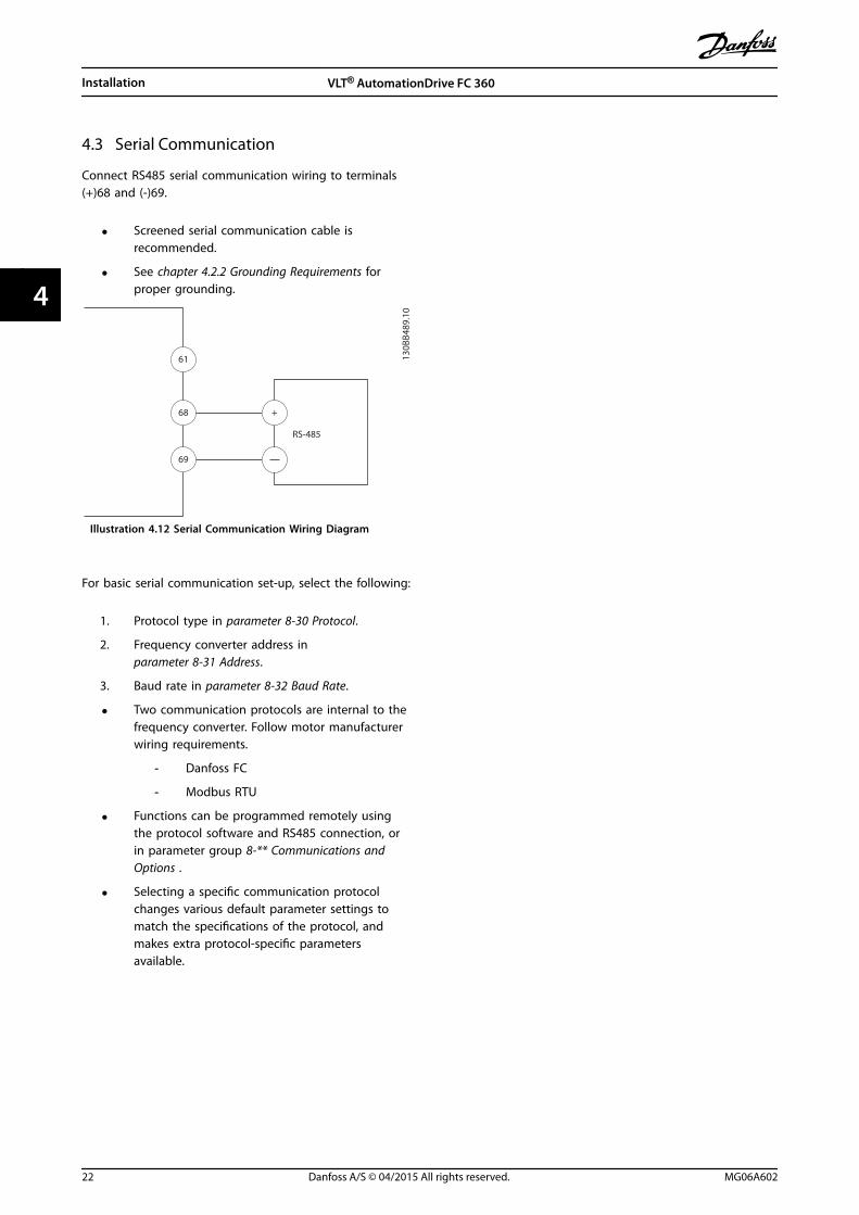
4.3 Serial Communication
Connect RS485 serial communication wiring to terminals(+)68 and (-)69.
• Screened serial communication cable isrecommended.
• See chapter 4.2.2 Grounding Requirements forproper grounding.
61
68
69
+13
0BB4
89.1
0
RS-485
Illustration 4.12 Serial Communication Wiring Diagram
For basic serial communication set-up, select the following:
1. Protocol type in parameter 8-30 Protocol.
2. Frequency converter address inparameter 8-31 Address.
3. Baud rate in parameter 8-32 Baud Rate.
• Two communication protocols are internal to thefrequency converter. Follow motor manufacturerwiring requirements.
- Danfoss FC
- Modbus RTU
• Functions can be programmed remotely usingthe protocol software and RS485 connection, orin parameter group 8-** Communications andOptions .
• Selecting a specific communication protocolchanges various default parameter settings tomatch the specifications of the protocol, andmakes extra protocol-specific parametersavailable.
Installation VLT® AutomationDrive FC 360
22 Danfoss A/S © 04/2015 All rights reserved. MG06A602
44
5 Local Control Panel and Programming
5.1 Local Control Panel (LCP) Operations
FC 360 supports numerical local control panel (LCP 21),graphic local control panel (LCP 102), and blind cover. Thischapter describes the operations with LCP 21 and LCP 102,as well as how to program with LCP 21.
NOTICEThe frequency converter can also be programmed fromthe MCT-10 Set-up Software on PC via RS485 com-port.This software can be ordered using code number130B1000 or downloaded from the Danfoss website:www.danfoss.com/BusinessAreas/DrivesSolutions/software-download.
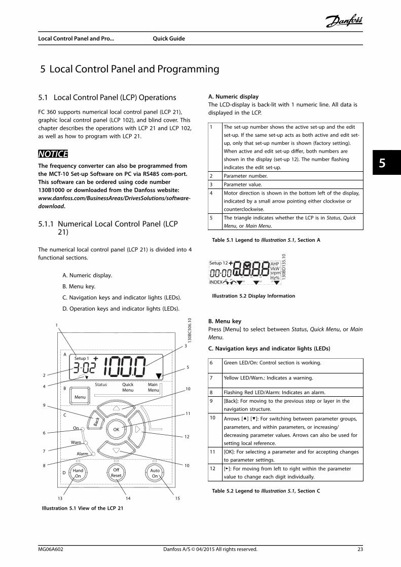
5.1.1 Numerical Local Control Panel (LCP21)
The numerical local control panel (LCP 21) is divided into 4functional sections.
A. Numeric display.
B. Menu key.
C. Navigation keys and indicator lights (LEDs).
D. Operation keys and indicator lights (LEDs).
130B
C506
.10
Setup 1A
B
C
D
5
12
13 14 15
10
11
10
9
6
7
8
4
1
2
3
Menu
Status QuickMenu
MainMenu
HandOn
OReset
AutoOn
Back
OKOn
Warn
Alarm
Illustration 5.1 View of the LCP 21
A. Numeric displayThe LCD-display is back-lit with 1 numeric line. All data isdisplayed in the LCP.
1 The set-up number shows the active set-up and the editset-up. If the same set-up acts as both active and edit set-up, only that set-up number is shown (factory setting).When active and edit set-up differ, both numbers areshown in the display (set-up 12). The number flashingindicates the edit set-up.
2 Parameter number.
3 Parameter value.
4 Motor direction is shown in the bottom left of the display,indicated by a small arrow pointing either clockwise orcounterclockwise.
5 The triangle indicates whether the LCP is in Status, QuickMenu, or Main Menu.
Table 5.1 Legend to Illustration 5.1, Section A
130B
D13
5.10
Setup 12
INDEX
AHPVkWsrpmHz%n2n1 n3
p5 p4p3 p2 p1
Illustration 5.2 Display Information
B. Menu keyPress [Menu] to select between Status, Quick Menu, or MainMenu.
C. Navigation keys and indicator lights (LEDs)
6 Green LED/On: Control section is working.
7 Yellow LED/Warn.: Indicates a warning.
8 Flashing Red LED/Alarm: Indicates an alarm.
9 [Back]: For moving to the previous step or layer in thenavigation structure.
10 Arrows [] []: For switching between parameter groups,
parameters, and within parameters, or increasing/decreasing parameter values. Arrows can also be used forsetting local reference.
11 [OK]: For selecting a parameter and for accepting changesto parameter settings.
12 []: For moving from left to right within the parametervalue to change each digit individually.
Table 5.2 Legend to Illustration 5.1, Section C
Local Control Panel and Pro... Quick Guide
MG06A602 Danfoss A/S © 04/2015 All rights reserved. 23
5 5

D. Operation keys and indicator lights (LEDs)
13 [Hand On]: Starts the motor and enables control of thefrequency converter via the LCP.
NOTICEParameter 5-12 Terminal 27 Digital Input has coastinverse as the default setting. This means that[Hand On] does not start the motor if there is no24 V to terminal 27.
14 [Off/Reset]: Stops the motor (off). If in alarm mode, thealarm is reset.
15 [Auto On]: The frequency converter is controlled either viacontrol terminals or serial communication.
Table 5.3 Legend to Illustration 5.1, Section D
WARNINGHIGH VOLTAGETouching the frequency converter after pressing the [Off/Reset] key is still dangerous, because the key does notdisconnect the frequency converter from the mains.
• Disconnect the frequency converter from themains, and wait for the frequency converter tofully discharge. See the discharge time inTable 2.1.
5.1.2 Local Control Panel LCP 102
The graphical local control panel (GLCP or LCP 102) has alarger display area, which displays more information thanLCP 21.
Autoon ResetHand
onO
StatusQuickMenu
MainMenu
AlarmLog
Cancel
Info
Status 1(1)1234rpm
Back
OK
43,5Hz
Run OK
43,5Hz
On
Alarm
Warn.
130B
C362
.10
a
b
c
d
1.0 A
Illustration 5.3 Local Control Panel LCP 102
a. Display area.
b. Menu keys for changing the display to showstatus, programming, or error message history.
c. Navigation keys for programming functions,moving the display cursor, and speed control inlocal operation. Also included are the statusindicator lights.
d. Operational mode keys and reset.
NOTICEThe [Info] key does not function when the LCP 102 isconnected to the frequency converter.
Functions
• English and Chinese display
• Status messages
Local Control Panel and Pro... VLT® AutomationDrive FC 360
24 Danfoss A/S © 04/2015 All rights reserved. MG06A602
55

• Quick menu for easy commissioning
• Parameter setting and explanation of parameterfunction
• Parameter adjustment
• Full parameter back-up and copy function
• Alarm logging
• Hand-operated start/stop, or automatic modeoption
• Reset function
MountingUse the GLCP adapter and a cable to connect the LCP 102to frequency converter, as shown in Illustration 5.4.
130B
D53
2.10
Illustration 5.4 GLCP Adapter and Connecting Cable
5.1.3 The Right-key Function on LCP 21
Press [] to edit any of the 4 digits on the displayindividually. When pressing [] once, the cursor moves tothe first digit and the digit starts flashing as shown inIllustration 5.5. Press the [] [] to change the value.Pressing [] does not change the value of the digits ormove the decimal point.
130B
C440
.10
Setup 1
Setup 1
Setup 1
Setup 1
Setup 1
Illustration 5.5 Right-key Function
[] can also be used for moving between parametergroups. When in Main Menu, press [] to move to the firstparameter in the next parameter group (for example, movefrom parameter 0-03 Regional Settings [0] International toparameter 1-00 Configuration Mode [0] Open loop).
5.2 Main Menu
The Main Menu gives access to all parameters.
1. To enter Main Menu, press [Menu] until theindicator in the display is placed above MainMenu.
2. [] []: Browse through the parameter groups.
3. Press [OK] to select a parameter group.
4. [] []: Browse through the parameters in thespecific group.
5. Press [OK] to select the parameter.
6. [] and [] []: Set/change the parameter value.
7. Press [OK] to accept the value.
8. To exit, press either [Back] twice (or 3 times forarray parameters) to enter Main Menu, or press[Menu] once to enter Status.
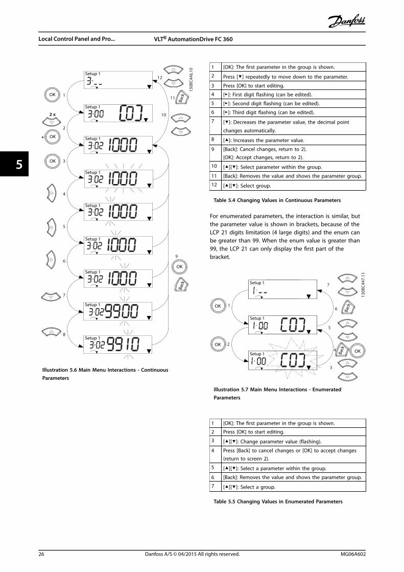
See Illustration 5.6, Illustration 5.7, and Illustration 5.8 for theprinciples of changing the value of continuous,enumerated, and array parameters, respectively. Theactions in the illustrations are described in Table 5.4,Table 5.5, and Table 5.6.
Local Control Panel and Pro... Quick Guide
MG06A602 Danfoss A/S © 04/2015 All rights reserved. 25
5 5
130B
C446
.10
Setup 1
Setup 1
Setup 1
Setup 1
Setup 1
Setup 1
Setup 1
Setup 1
1
2
3
4
5
6
7
10
11
12
OK
OK
Back
8
Back
Setup 1
2 x
+ OK
9
OK
Illustration 5.6 Main Menu Interactions - ContinuousParameters
1 [OK]: The first parameter in the group is shown.
2 Press [] repeatedly to move down to the parameter.
3 Press [OK] to start editing.
4 []: First digit flashing (can be edited).
5 []: Second digit flashing (can be edited).
6 []: Third digit flashing (can be edited).
7 []: Decreases the parameter value, the decimal point
changes automatically.
8 []: Increases the parameter value.
9 [Back]: Cancel changes, return to 2).[OK]: Accept changes, return to 2).
10 [][]: Select parameter within the group.
11 [Back]: Removes the value and shows the parameter group.
12 [][]: Select group.
Table 5.4 Changing Values in Continuous Parameters
For enumerated parameters, the interaction is similar, butthe parameter value is shown in brackets, because of theLCP 21 digits limitation (4 large digits) and the enum canbe greater than 99. When the enum value is greater than99, the LCP 21 can only display the first part of thebracket.
130B
C447
.11
Setup 1
Setup 1
Setup 1
1
2
3
4
5
6OK
OKBa
ck
7
OKBack
Illustration 5.7 Main Menu Interactions - EnumeratedParameters
1 [OK]: The first parameter in the group is shown.
2 Press [OK] to start editing.
3 [][]: Change parameter value (flashing).
4 Press [Back] to cancel changes or [OK] to accept changes(return to screen 2).
5 [][]: Select a parameter within the group.
6 [Back]: Removes the value and shows the parameter group.
7 [][]: Select a group.
Table 5.5 Changing Values in Enumerated Parameters
Local Control Panel and Pro... VLT® AutomationDrive FC 360
26 Danfoss A/S © 04/2015 All rights reserved. MG06A602
55

Array parameters function as follows:
130B
C448
.10
1
2
4
5
6
7
8
9
10
OK
Back
Back
Back
5 x
Setup 1
Setup 1
Setup 1
Setup 1
%INDEX
%INDEX
%INDEX
Setup 1
INDEX%
OK
OK
OK
Illustration 5.8 Main Menu Interactions - Array Parameters
1 [OK]: Shows parameter numbers and the value in the firstindex.
2 [OK]: Index can be selected.
3 [][]: Select index.
4 [OK]: Value can be edited.
5 [][]: Change parameter value (flashing).
6 [Back]: Cancels changes.[OK]: Accepts changes.
7 [Back]: Cancels editing index, a new parameter can beselected.
8 [][]: Select parameter within the group.
9 [Back]: Removes parameter index value and shows theparameter group.
10 [][]: Select group.
Table 5.6 Changing Values in Array Parameters
5.3 Quick Menu
The Quick Menu gives easy access to the most frequentlyused parameters.
1. To enter Quick Menu, press [Menu] until theindicator in display is placed above Quick Menu.
2. Press [] [] to select either QM1 or QM2, thenpress [OK].
3. Press [] [] to browse through the parameters inQuick Menu.
4. Press [OK] to select a parameter.
5. Press [] [] to change the value of a parametersetting.
6. Press [OK] to accept the change.
7. To exit, press either [Back] twice (or 3 times if inQM2 and QM3) to enter Status, or press [Menu]once to enter Main Menu.
Local Control Panel and Pro... Quick Guide
MG06A602 Danfoss A/S © 04/2015 All rights reserved. 27
5 5

130BC445.12
1-22
XXX
X V
Mot
or
nom
inal
sp
eed
QM 1
0-01
[0]
1-10
[0]
1-24
XXX
X A
Lang
uage
Mot
or Ty
pe
PM M
otor
Asyn
chro
nous
Mot
or
1-20
XXX
X kW
Mot
or p
ower
Mot
or vo
ltage
Mot
or C
ont.
Rat
ed To
rque
1-26
XXX
X1-
23 X
XXX
Hz
Stat
or
Resis
tanc
e
Mot
or fr
eque
ncy
1-25
XXX
X rp
m
(Rs)
1-30
XXX
X
1-39
XXX
X
1-40
XXX
X
1-37
XXX
X
1-25
XXX
X rp
m
1-24
XXX
X A
Mot
or C
urre
nt
3-02
XXX
X Hz
3-03
XXX
X Hz
3-41
XXX
X S
3-42
XXX
X S
5-12
[2]
1-29
[1]
Min
imum
Ref
eren
ce
Max
imum
Ref
eren
ce
Ram
p 1
Ram
p up
Tim
e
Ram
p 1
Ram
p Do
wn
Tim
e
Term
inal
27
Digi
tal in
put
AMA
Mot
or P
oles
Back
EMF a
t 10
00 R
PM
d-ax
is In
duct
ance
(Ld)
Basic
Mot
or S
etup
Adv.
Mot
or S
etup
Enco
der S
etup
QM 2
BMS
AMS
ES
5-70
XXX
X
5-71
[0]
1-30
XXX
X
1-39
XXX
X
1-90
[0]
2-10
[0]
4-16
XXX
X %
4-17
XXX
X %
4-18
XXX
X %
1-00
[0]
1-01
[1]
1-10
[0]
1-24
XXX
X A
1-20
XXX
X kW
1-22
XXX
X V
Mot
or
nom
inal
sp
eed
PM M
otor
Asyn
chro
nous
Mot
or
Mot
or p
ower
Mot
or vo
ltage
Mot
or C
ont.
Rate
d To
rque
1-26
XXX
X1-
23 X
XXX
Hz
Stat
or
Resis
tanc
e
Mot
or fr
eque
ncy
1-25
XXX
X rp
m
(Rs)
1-30
XXX
X
1-40
XXX
X
1-37
XXX
X
1-25
XXX
X rp
m
1-24
XXX
X A
Mot
or C
urre
nt
Mot
or P
oles
Back
EMF a
t 10
00 R
PM
d-ax
is In
duct
ance
(Ld)
1-39
XXX
X 4-19
XXX
X Hz
4-14
XXX
X Hz
Stat
or
Resis
tanc
e (R
s)
Mot
or P
oles
Mot
or
Ther
mal
Pro
tect
ion
Brak
e Fu
nctio
n
Torq
ue Li
mit
Mot
or M
ode
Torq
ue Li
mit
Gene
rato
r Mod
e
Curre
nt Li
mit
Term
32/
33 P
ulse
s pe
r Rev
olut
ion
Term
32/
33
Enco
der D
irect
ion
QM 3
QM 4
QM 5
L10C
SFS
Last
10
Chan
ges
Sinc
e Fa
ctor
y Set
ting
Chan
ges M
ade
Alar
m Lo
gTB
D
Mot
or C
urre
nt
Mot
or
nom
inal
sp
eed
Mot
or
nom
inal
sp
eed
Mot
or
Curre
nt M
ode
Mot
or C
ontro
l Pr
incip
le
Mot
or Ty
pe
Mot
or S
peed
Hig
h Li
mit
[Hz]
Max
Out
put F
requ
ency
Illus
trat
ion
5.9
Qui
ck M
enu
Str
uctu
re
Local Control Panel and Pro... VLT® AutomationDrive FC 360
28 Danfoss A/S © 04/2015 All rights reserved. MG06A602
55

5.4 PM Motor Set-up
Initial programming steps
1. Set parameter 1-10 Motor Construction to thefollowing options to activate PM motor operation:
1a [1] PM, non salient SPM
1b [2] PM, salient IPM, non Sat
1c [3] PM, salient IPM, Sat
2. Select [0] Open Loop in parameter 1-00 Configu-ration Mode.
NOTICEEncoder feedback is not supported for PM motors.
Programming motor dataWhen the initial programming steps are completed, the PMmotor-related parameters in parameter groups 1-2* MotorData, 1-3* Adv. Motor Data, and 1-4* are active.The information can be found on the motor nameplateand in the motor datasheet.Programme the following parameters in the listed order:
1. Parameter 1-24 Motor Current.
2. Parameter 1-26 Motor Cont. Rated Torque.
3. Parameter 1-25 Motor Nominal Speed.
4. Parameter 1-39 Motor Poles.
Run a complete AMA using parameter 1-29 AutomaticMotor Adaption (AMA)[1] Enable Complete AMA. If acomplete AMA is not performed successfully, configure thefollowing parameters manually.
1. Parameter 1-30 Stator Resistance (Rs).Enter phase common stator winding resistance(Rs). If only phase-to-phase data is available,divide the phase-to-phase value by 2 to achievethe phase value.It is also possible to measure the value with anohmmeter, which also takes the resistance of thecable into account. Divide the measured value by2 and enter the result.
2. Parameter 1-37 d-axis Inductance (Ld).Enter direct axis inductance of the PM motor.If only phase-to-phase data is available, divide thephase-to-phase value by 2 to achieve the phasevalue.It is also possible to measure the value with aninductance meter, which also takes theinductance of the cable into account. Perform themeasurement multiple times to get the maximumphase-to-phase inductance value. Divide thevalue by 2 and enter the result.
3. Parameter 1-38 q-axis Inductance (Lq).
This parameter is active only whenparameter 1-10 Motor Construction is set to [2] PM,salient IPM, non Sat or [3] PM, salient IPM, Sat.Enter the quadrature axis inductance of the PMmotor. If only phase-to-phase data is available,divide the phase-to-phase value by 2 to achievethe phase value.It is also possible to measure the value with aninductance meter, which also takes theinductance of the cable into account. Perform themeasurement multiple times to get the minimumphase-to-phase inductance value. Divide thevalue by 2 and enter the result.
4. Parameter 1-44 d-axis Inductance Sat. (LdSat).This parameter is active only whenparameter 1-10 Motor Construction is set to [3] PM,salient IPM, Sat.This parameter corresponds to the saturationinductance of d-axis. The default value is thevalue set in parameter 1-37 d-axis Inductance (Ld).Do not change the default value in most cases. Ifthe motor supplier provides the saturation curve,enter the d-axis inductance value, which is 100%of the nominal current.
5. Parameter 1-45 q-axis Inductance Sat. (LqSat).This parameter is active only whenparameter 1-10 Motor Construction is set to [3] PM,salient IPM, Sat.This parameter corresponds to the saturationinductance of q-axis. The default value is thevalue set in parameter 1-38 q-axis Inductance (Lq).In most cases, do not change the default. If themotor supplier provides the saturation curve,enter the q-axis inductance value, which is 100%of the nominal current.
6. Parameter 1-40 Back EMF at 1000 RPM.Enter the phase-to-phase back EMF RMS value ofthe PM motor at 1000 RPM mechanical speed.Back EMF is the voltage generated by a PM motorwhen no frequency converter is connected, andthe shaft is turned externally. Back EMF isnormally specified for nominal motor speed or for1000 RPM measured between 2 lines. If the valueis not available for a motor speed of 1000 RPM,calculate the correct value as follows: Forexample, if back EMF at 1800 RPM is 320 V, theback EMF at 1000 RPM is:Back EMF=(Voltage/RPM)x1000=(320/1800)x1000=178.Program this value for parameter 1-40 Back EMF at1000 RPM.
Local Control Panel and Pro... Quick Guide
MG06A602 Danfoss A/S © 04/2015 All rights reserved. 29
5 5

Test motor operation
1. Start the motor at low speed (100`1200 RPM). Ifthe motor does not turn, check installation,general programming, and motor data.
2. Check if the start function in parameter 1-70 PMStart Mode fits the application requirements.
Rotor detectionThis function is the recommended selection forapplications where the motor starts from standstill, forexample pumps or conveyors. For some motors, a sound isheard when the frequency converter performs the rotordetection. This sound does not harm the motor. Adjust thevalue in parameter 1-46 Position Detection Gain for differentmotors. If the frequency converter fails to start, or anovercurrent alarm occurs when the frequency converterstarts, check if the rotor is blocked or not. If the rotor isnot blocked, set parameter 1-70 PM Start Mode to [1]Parking and try again.
ParkingThis function is the recommended option for applicationswhere the motor is rotating at low speed, for examplewindmilling in fan applications. Parameter 2-06 ParkingCurrent and parameter 2-07 Parking Time are adjustable.Increase the factory setting of these parameters forapplications with high inertia.
Start the motor at nominal speed (100–200 RPM). If theapplication does not run well, check the VVC+ PM settings.Table 5.7 shows recommendations in different applications.
Application Settings
Low inertia applications
ILoad1)/IMotor2) <5• Increase the value for
parameter 1-17 Voltage filter timeconst. by factor 5 to 10.
• Reduce the value forparameter 1-14 Damping Gain.
• Reduce the value (<100%) forparameter 1-66 Min. Current atLow Speed.
Medium inertiaapplications50>ILoad/IMotor >5
Keep calculated values.
High inertia applicationsILoad/IMotor > 50
Increase the values forparameter 1-14 Damping Gain,parameter 1-15 Low Speed Filter TimeConst., and parameter 1-16 HighSpeed Filter Time Const.
High load at low speed<30% (rated speed)
Decrease parameter 1-17 Voltagefilter time const.Decrease parameter 1-66 Min. Currentat Low Speed (>100% for longer timecan overheat the motor).
Table 5.7 Recommendations in Different Applications
1) ILoad=The inertia of load.
2) IMotor=The inertia of motor
If the motor starts oscillating at a certain speed, increaseparameter 1-14 Damping Gain. Increase the value in smallsteps.
Adjust the starting torque in parameter 1-66 Min. Current atLow Speed. 100% provides nominal torque as startingtorque.
Local Control Panel and Pro... VLT® AutomationDrive FC 360
30 Danfoss A/S © 04/2015 All rights reserved. MG06A602
55

5.5 PROFIBUS
FC 360 frequency converters support PROFIBUS. IfPROFIBUS is needed,
• Order a new frequency converter on which thecontrol cassette with PROFIBUS is pre-installed;
• Order a control cassette with PROFIBUS to replacethe standard control cassette on an existingfrequency converter. In this case, upgrade thefirmware with MCT-10 Set-up Software.
In both cases, ensure that parameter 15-43 Software Versionis higher than 1.20.
Illustration 5.10 shows the front panel of a control cassettewith PROFIBUS.
1
2
130B
D65
0.10
1 Termination resistor switch
2 PROFIBUS address selector
Illustration 5.10 Front Panel of a Control Cassette withPROFIBUS
The functions of the LEDs and switches on the front panelare introduced in Table 5.8.
LED/Switch Description
NS2 Not used for PROFIBUS.
NS1 Indicates the network status when communi-cating with the PROFIBUS master. When thisindicator light shows constant green, dataexchange between the master and the frequencyconverter is active.
MS Indicates the module status, which is acyclic DPV1 communication from either a PROFIBUSmaster class 1 (PLC) or a master class 2 (MCT-10Set-up Software, FDT tool). When this indicatorlight shows constant green, DP V1 communi-cation from master classes 1 and 2 is active.
COM Communication status for RS485. Not used forPROFIBUS.
Terminationresistorswitch
When the switch is turned on, the terminationresistor is in effect.
PROFIBUSaddressselector
Use the switches in the selector to set thePROFIBUS address. The address change comesinto effect at the next power-up.
NOTICESwitch off the power supply beforechanging the switches.
Table 5.8 Functions of LEDs and Switches
Local Control Panel and Pro... Quick Guide
MG06A602 Danfoss A/S © 04/2015 All rights reserved. 31
5 5
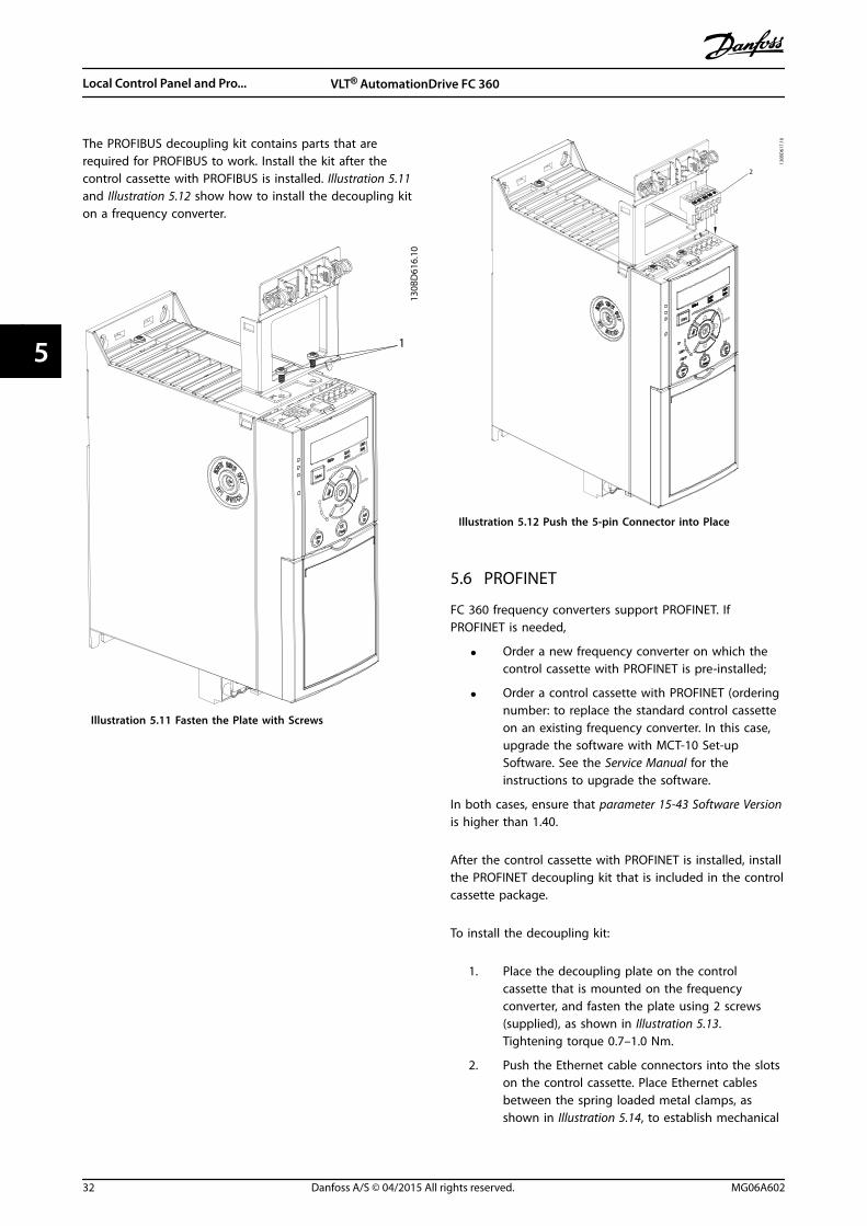
The PROFIBUS decoupling kit contains parts that arerequired for PROFIBUS to work. Install the kit after thecontrol cassette with PROFIBUS is installed. Illustration 5.11and Illustration 5.12 show how to install the decoupling kiton a frequency converter.
1
130B
D61
6.10
Illustration 5.11 Fasten the Plate with Screws
130B
D61
7.10
2
Illustration 5.12 Push the 5-pin Connector into Place
5.6 PROFINET
FC 360 frequency converters support PROFINET. IfPROFINET is needed,
• Order a new frequency converter on which thecontrol cassette with PROFINET is pre-installed;
• Order a control cassette with PROFINET (orderingnumber: to replace the standard control cassetteon an existing frequency converter. In this case,upgrade the software with MCT-10 Set-upSoftware. See the Service Manual for theinstructions to upgrade the software.
In both cases, ensure that parameter 15-43 Software Versionis higher than 1.40.
After the control cassette with PROFINET is installed, installthe PROFINET decoupling kit that is included in the controlcassette package.
To install the decoupling kit:
1. Place the decoupling plate on the controlcassette that is mounted on the frequencyconverter, and fasten the plate using 2 screws(supplied), as shown in Illustration 5.13.Tightening torque 0.7–1.0 Nm.
2. Push the Ethernet cable connectors into the slotson the control cassette. Place Ethernet cablesbetween the spring loaded metal clamps, asshown in Illustration 5.14, to establish mechanical
Local Control Panel and Pro... VLT® AutomationDrive FC 360
32 Danfoss A/S © 04/2015 All rights reserved. MG06A602
55
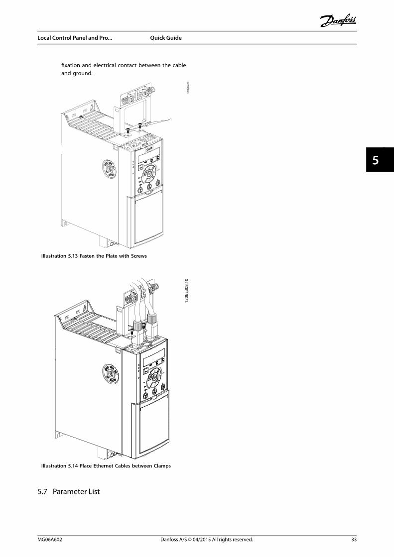
fixation and electrical contact between the cableand ground.
1
130B
E332
.10
Illustration 5.13 Fasten the Plate with Screws
130B
E308
.10
Illustration 5.14 Place Ethernet Cables between Clamps
5.7 Parameter List
Local Control Panel and Pro... Quick Guide
MG06A602 Danfoss A/S © 04/2015 All rights reserved. 33
5 5
0-**
Ope
ratio
n /
Dis
play
0-0*
Basi
c Se
ttin
gs0-
01La
ngua
ge0-
03Re
gion
al S
ettin
gs0-
04O
pera
ting
Sta
te a
t Po
wer
-up
0-06
Grid
Type
[10]
>380
-440
V/50
Hz/
IT-g
rid<
[11]
>380
-440
V/50
Hz/
Del
ta<
[12]
>380
-440
V/50
Hz<
[20]
>440
-480
V/50
Hz/
IT-g
rid<
[21]
>440
-480
V/50
Hz/
Del
ta<
[22]
>440
-480
V/50
Hz<
[110
]>3
80-4
40V/
60H
z/IT
-grid
<[1
11]
>380
-440
V/60
Hz/
Del
ta<
[112
]>3
80-4
40V/
60H
z<[1
20]
>440
-480
V/60
Hz/
IT-g
rid<
[121
]>4
40-4
80V/
60H
z/D
elta
<[1
22]
>440
-480
V/60
Hz<
0-07
Auto
DC
Bra
king
0-1*
Set-
up O
pera
tions
0-10
Activ
e Se
t-up
*[1]
>Set
-up
1<
[2]
>Set
-up
2<
[9]
>Mul
ti S
et-u
p<0-
11Pr
ogra
mm
ing
Set
-up
0-12
Link
Set
ups
0-14
Read
out:
Edi
t Se
t-up
s /
Chan
nel
0-16
App
licat
ion
Sel
ectio
n*[
0]N
one
[1]
>Pro
cess
Clo
se L
oop<
[2]
>Loc
al/R
emot
e<[3
]>S
peed
Ope
n L
oop<
[4]
>Spe
ed C
lose
Loo
p<[5
]>M
ulti
Spe
ed<
[6]
>OG
D<
0-2*
LCP
Dis
play
0-20
Dis
play
Lin
e 1.
1 Sm
all
0-21
Dis
play
Lin
e 1.
2 Sm
all
0-22
Dis
play
Lin
e 1.
3 Sm
all
0-23
Dis
play
Lin
e 2
Larg
e0-
24D
ispl
ay L
ine
3 La
rge
0-3*
LCP
Cus
tom
Rea
dout
0-30
Cust
om R
eado
ut U
nit
0-31
Cust
om R
eado
ut M
in V
alue
0-32
Cust
om R
eado
ut M
ax V
alue
0-37
Dis
play
Tex
t 1
0-38
Dis
play
Tex
t 2
0-39
Dis
play
Tex
t 3
0-4*
LCP
Key
pad
0-40
[Han
d o
n] K
ey o
n L
CP0-
42[A
uto
on]
Key
on
LCP
0-44
[Off/
Rese
t] K
ey o
n L
CP0-
5*Co
py/S
ave
0-50
LCP
Cop
y*[
0]>N
o c
opy<
[1]
>All
to L
CP<
[2]
>All
from
LCP
<[3
]>S
ize
inde
p. fr
om L
CP<
0-51
Set-
up C
opy
*[0]
>No
cop
y[1
]>C
opy
from
set
up 1
<[2
]>C
opy
from
set
up 2
<[9
]>C
opy
from
Fac
tory
set
up<
0-6*
Pass
wor
d0-
60M
ain
Men
u P
assw
ord
1-**
Load
and
Mot
or1-
0*G
ener
al S
ettin
gs1-
00Co
nfigu
ratio
n M
ode
[0]*
>Ope
n L
oop<
[1]
>Spe
ed c
lose
d lo
op<
[2]
>Tor
que
clos
ed lo
op<
[3]
>Pro
cess
Clo
sed
Loo
p<[4
]>T
orqu
e op
en lo
op<
[6]
>Sur
face
Win
der<
[7]
>Ext
ende
d P
ID S
peed
OL<
1-01
Mot
or C
ontr
ol P
rinci
ple
[0]
>U/f
<*[
1]>V
VC+<
1-03
Torq
ue C
hara
cter
istic
s*[
0]>C
onst
ant
torq
ue<
[1]
>Var
iabl
e To
rque
<[2
]>A
uto
Ene
rgy
Opt
im. C
T<1-
06Cl
ockw
ise
Dire
ctio
n1-
08M
otor
Con
trol
Ban
dwid
th1-
1*M
otor
Sel
ectio
n1-
10M
otor
Con
stru
ctio
n1-
14D
ampi
ng G
ain
1-15
Low
Spe
ed F
ilter
Tim
e Co
nst.
1-16
Hig
h S
peed
Filt
er T
ime
Cons
t.1-
17Vo
ltage
filte
r tim
e co
nst.
1-2*
Mot
or D
ata
1-20
Mot
or P
ower
[2]
>0.1
2 kW
- 0
.16
hp<
[3]
>0.1
8 kW
- 0
.25
hp<
[4]
>0.2
5 kW
- 0
.33
hp<
[5]
>0.3
7 kW
- 0
.5 h
p<[6
]>0
.55
kW -
0.7
5 hp
<[7
]>0
.75
kW -
1 h
p<[8
]>1
.1 k
W -
1 h
p<[9
]>1
.5 k
W -
2 h
p<[1
0]>2
.2 k
W -
3 h
p<[1
1]>3
kW
- 4
hp<
[12]
>3.7
kW
- 5
hp<
[13]
>4 k
W -
5.4
hp<
[14]
>5.5
kW
- 7
.5 h
p<[1
5]>7
.5 k
W -
10
hp<
[16]
>11
kW -
15
hp<
[17]
>15
kW -
20
hp<
[18]
>18.
5 kW
- 2
5 hp
<[1
9]>2
2 kW
- 3
0 hp
<[2
0]>3
0 kW
- 4
0 hp
<[2
1]>3
7 kW
- 5
0 hp
<[2
2]>4
5 kW
- 6
0 hp
<[2
3]>5
5 kW
- 7
5 hp
<[2
4]>7
5 kW
- 1
00 h
p<[2
5]>9
0 kW
- 1
20 h
p<[2
6]>1
10 k
W -
150
hp<
1-22
Mot
or V
olta
ge
1-23
Mot
or F
requ
ency
1-24
Mot
or C
urre
nt1-
25M
otor
Nom
inal
Spe
ed1-
26M
otor
Con
t. R
ated
Tor
que
1-29
Auto
mat
ic M
otor
Ada
ptio
n (A
MA
)*[
0]>O
ff<[1
]>E
nabl
e Co
mpl
ete
AM
A<
[2]
>Ena
ble
Redu
ced
AM
A<
1-3*
Adv
. Mot
or D
ata
I1-
30St
ator
Res
ista
nce
(Rs)
1-31
Roto
r Re
sist
ance
(Rr)
1-33
Stat
or L
eaka
ge R
eact
ance
(X1)
1-35
Mai
n R
eact
ance
(Xh)
1-37
d-ax
is In
duct
ance
(Ld)
1-38
q-ax
is In
duct
ance
(Lq)
1-39
Mot
or P
oles
1-4*
Adv
. Mot
or D
ata
II1-
40Ba
ck E
MF
at 1
000
RPM
1-42
Mot
or C
able
Len
gth
1-43
Mot
or C
able
Len
gth
Fee
t1-
5*Lo
ad In
dep.
Set
ting
1-50
Mot
or M
agne
tisat
ion
at
Zero
Spe
ed1-
52M
in S
peed
Nor
mal
Mag
netis
ing
[Hz]
1-55
U/f
Cha
ract
eris
tic -
U1-
56U
/f C
hara
cter
istic
- F
1-6*
Load
Dep
en. S
ettin
g1-
60Lo
w S
peed
Loa
d C
ompe
nsat
ion
1-61
Hig
h S
peed
Loa
d C
ompe
nsat
ion
1-62
Slip
Com
pens
atio
n1-
63Sl
ip C
ompe
nsat
ion
Tim
e Co
nsta
nt1-
64Re
sona
nce
Dam
peni
ng1-
65Re
sona
nce
Dam
peni
ng T
ime
Cons
tant
1-66
Min
. Cur
rent
at
Low
Spe
ed1-
7*St
art
Adj
ustm
ents
1-71
Star
t D
elay
1-72
Star
t Fu
nctio
n[0
]>D
C H
old/
dela
y tim
e<*[
2]>C
oast
/del
ay t
ime<
[3]
>Sta
rt s
peed
cw
<[4
]>H
oriz
onta
l ope
ratio
n<[5
]>V
VC+
clo
ckw
ise<
1-73
Flyi
ng S
tart
*[0]
>Dis
able
d<[1
]>E
nabl
ed<
[2]
>Ena
bled
Alw
ays<
[3]
>Ena
bled
Ref
. Dir.
<[4
]>E
nab.
Alw
ays
Ref.
Dir.
<1-
75St
art
Spee
d [H
z]1-
76St
art
Curr
ent
1-78
Com
pres
sor
Star
t M
ax S
peed
[Hz]
1-79
Com
pres
sor
Star
t M
ax T
ime
to T
rip1-
8*St
op A
djus
tmen
ts1-
80Fu
nctio
n a
t St
op*[
0]>C
oast
<[1
]>D
C h
old
/ M
otor
Pre
heat
<[3
]>P
re-m
agne
tizin
g<1-
82M
in S
peed
for
Func
tion
at
Stop
[Hz]
1-9*
Mot
or T
empe
ratu
re1-
90M
otor
The
rmal
Pro
tect
ion
*[0]
>No
pro
tect
ion<
[1]
>The
rmis
tor
war
ning
<[2
]>T
herm
isto
r tr
ip<
[3]
>ETR
war
ning
1<
[4]
>ETR
trip
1<
1-93
Ther
mis
tor
Sour
ce2-
**Br
akes
2-0*
DC-
Brak
e2-
00D
C H
old/
Mot
or P
rehe
at C
urre
nt2-
01D
C B
rake
Cur
rent
2-02
DC
Bra
king
Tim
e2-
04D
C B
rake
Cut
In S
peed
2-06
Park
ing
Cur
rent
2-07
Park
ing
Tim
e2-
1*Br
ake
Ener
gy F
unct
.2-
10Br
ake
Func
tion
*[0]
>Off<
[1]
>Res
isto
r br
ake<
[2]
>AC
bra
ke<
2-11
Brak
e Re
sist
or (o
hm)
2-12
Brak
e Po
wer
Lim
it (k
W)
2-14
Brak
e vo
ltage
redu
ce2-
16AC
Bra
ke, M
ax c
urre
nt2-
17O
ver-
volta
ge C
ontr
ol*[
0]>D
isab
led<
[1]
>Ena
bled
(not
at
stop
)<[2
]>E
nabl
ed<
2-19
Ove
r-vo
ltage
Gai
n2-
2*M
echa
nica
l Bra
ke2-
20Re
leas
e Br
ake
Curr
ent
2-22
Activ
ate
Brak
e Sp
eed
[Hz]
2-23
Activ
ate
Brak
e D
elay
3-**
Refe
renc
e /
Ram
ps3-
0*Re
fere
nce
Lim
its3-
00Re
fere
nce
Rang
e*[
0]>M
in -
Max
<[1
]>-
Max
- +
Max
<3-
01Re
fere
nce/
Feed
back
Uni
t3-
02M
inim
um R
efer
ence
3-03
Max
imum
Ref
eren
ce3-
04Re
fere
nce
Func
tion
*[0]
>Sum
<[1
]>E
xter
nal/P
rese
t<3-
1*Re
fere
nces
3-10
Pres
et R
efer
ence
>-10
0-10
0%<
*0%
3-11
Jog
Spe
ed [H
z]3-
12Ca
tch
up/
slow
Dow
n V
alue
3-14
Pres
et R
elat
ive
Refe
renc
e3-
15Re
fere
nce
1 So
urce
[0]
>No
func
tion<
*[1]
>Ana
log
Inpu
t 53
<[2
]>A
nalo
g In
put
54<
[7]
>Fre
quen
cy in
put
29<
[8]
>Fre
quen
cy in
put
33<
[11]
>Loc
al b
us r
efer
ence
<[3
2]>B
us P
CD<
3-16
Refe
renc
e 2
Sour
ce3-
17Re
fere
nce
3 So
urce
3-18
Rela
tive
Scal
ing
Ref
eren
ce R
esou
rce
3-4*
Ram
p 1
3-40
Ram
p 1
Typ
e*[
0]>L
inea
r<[2
]>S
-ram
p C
onst
Tim
e<3-
41Ra
mp
1 R
amp
Up
Tim
e>0
.05-
3600
s<
* S
ize
rela
ted
3-42
Ram
p 1
Ram
p D
own
Tim
e>0
.05-
3600
s<
* S
ize
rela
ted
3-5*
Ram
p 2
3-50
Ram
p 2
Typ
e3-
51Ra
mp
2 R
amp
Up
Tim
e3-
52Ra
mp
2 R
amp
Dow
n T
ime
3-6*
Ram
p 3
3-60
Ram
p 3
Typ
e3-
61Ra
mp
3 R
amp
up
Tim
e3-
62Ra
mp
3 R
amp
dow
n T
ime
3-7*
Ram
p 4
3-70
Ram
p 4
Typ
e3-
71Ra
mp
4 R
amp
up
Tim
e3-
72Ra
mp
4 R
amp
Dow
n T
ime
3-8*
Oth
er R
amps
3-80
Jog
Ram
p T
ime
3-81
Qui
ck S
top
Ram
p T
ime
3-9*
Dig
ital P
oten
tiom
eter
3-90
Step
Siz
e3-
92Po
wer
Res
tore
3-93
Max
imum
Lim
it3-
94M
inim
um L
imit
3-95
Ram
p D
elay
4-**
Lim
its /
War
ning
s4-
1*M
otor
Lim
its4-
10M
otor
Spe
ed D
irect
ion
[0]
>Clo
ckw
ise<
*[2]
>Bot
h d
irect
ions
<4-
12M
otor
Spe
ed L
ow L
imit
[Hz]
4-14
Mot
or S
peed
Hig
h L
imit
[Hz]
4-16
Torq
ue L
imit
Mot
or M
ode
4-17
Torq
ue L
imit
Gen
erat
or M
ode
4-18
Curr
ent
Lim
it4-
19M
ax O
utpu
t Fr
eque
ncy
4-2*
Lim
it F
acto
rs4-
20To
rque
Lim
it F
acto
r So
urce
4-21
Spee
d L
imit
Fac
tor
Sour
ce4-
22Br
eak
Away
Boo
st4-
3*M
otor
Fb
Mon
itor
4-30
Mot
or F
eedb
ack
Loss
Fun
ctio
n4-
31M
otor
Fee
dbac
k Sp
eed
Err
or4-
32M
otor
Fee
dbac
k Lo
ss T
imeo
ut4-
4*A
dj. W
arni
ngs
24-
40W
arni
ng F
req.
Low
4-41
War
ning
Fre
q. H
igh
4-42
Adju
stab
le T
empe
ratu
re W
arni
ng4-
5*A
dj. W
arni
ngs
4-50
War
ning
Cur
rent
Low
4-51
War
ning
Cur
rent
Hig
h4-
54W
arni
ng R
efer
ence
Low
4-55
War
ning
Ref
eren
ce H
igh
4-56
War
ning
Fee
dbac
k Lo
w
Local Control Panel and Pro... VLT® AutomationDrive FC 360
34 Danfoss A/S © 04/2015 All rights reserved. MG06A602
55

4-57
War
ning
Fee
dbac
k H
igh
4-58
Mis
sing
Mot
or P
hase
Fun
ctio
n4-
6*Sp
eed
Byp
ass
4-61
Bypa
ss S
peed
Fro
m [H
z]4-
63By
pass
Spe
ed T
o [H
z]5-
**D
igita
l In/
Out
5-0*
Dig
ital I
/O m
ode
5-00
Dig
ital I
/O M
ode
*[0]
>PN
P<[1
]>N
PN<
5-01
Term
inal
27
Mod
e5-
02Te
rmin
al 2
9 M
ode
5-1*
Dig
ital I
nput
s5-
10Te
rmin
al 1
8 D
igita
l Inp
ut[0
]>N
o o
pera
tion<
[1]
>Res
et<
[2]
>Coa
st in
vers
e<[3
]>C
oast
and
rese
t in
v<[4
]>Q
uick
sto
p in
vers
e<[5
]>D
C-br
ake
inve
rse<
[6]
>Sto
p in
vers
e<*[
8]>S
tart
<[9
]>L
atch
ed s
tart
<[1
0]>R
ever
sing
<[1
1]>S
tart
reve
rsin
g<[1
2]>E
nabl
e st
art
forw
ard<
[13]
>Ena
ble
star
t re
vers
e<[1
4]>J
og<
[15]
>Pre
set
refe
renc
e on
<[1
6]>P
rese
t re
f bi
t 0<
[17]
>Pre
set
ref
bit
1<[1
8]>P
rese
t re
f bi
t 2<
[19]
>Fre
eze
refe
renc
e<[2
0]>F
reez
e ou
tput
<[2
1]>S
peed
up<
[22]
>Spe
ed d
own<
[23]
>Set
-up
sel
ect
bit
0<[2
6]>P
reci
se s
top
inve
rse<
[28]
>Cat
ch u
p<[2
9]>S
low
dow
n<[3
4]>R
amp
bit
0<
[35]
>Ram
p b
it 1
<[5
1]>E
xter
nal I
nter
lock
<[6
0]>C
ount
er A
(up)
<[6
1]>C
ount
er A
(dow
n)<
[62]
>Res
et C
ount
er A
<[6
3]>C
ount
er B
(up)
<[6
4]>C
ount
er B
(dow
n)<
[65]
>Res
et C
ount
er B
<[7
2]>P
ID e
rror
inve
rse<
[73]
>PID
rese
t I p
art<
[74]
>PID
ena
ble<
[150
]>G
o T
o H
ome<
[151
]>H
ome
Ref.
Swtic
h<[1
55]
>HW
Lim
it P
ositi
ve<
[156
]>H
W L
imit
Neg
ativ
e<[1
57]
>Pos
. Qui
ck S
top<
[160
]>G
o T
o T
arge
t Po
s<[1
62]
>Pos
. Idx
Bit0
<
[163
]>P
os. I
dx B
it1<
[164
]>P
os. I
dx B
it2<
[165
]Co
re d
iam
eter
sou
rce
[166
]N
ew d
iam
eter
sel
ect
[167
]Re
set
diam
eter
[168
]W
inde
r jo
g fo
rwar
d[1
69]
Win
der
jog
rev
erse
[170
]Te
nsio
n o
n5-
11Te
rmin
al 1
9 D
igita
l Inp
ut5-
12Te
rmin
al 2
7 D
igita
l Inp
ut5-
13Te
rmin
al 2
9 D
igita
l Inp
ut[3
2]Pu
lse
time
base
d5-
14Te
rmin
al 3
2 D
igita
l Inp
ut[8
2]En
code
r in
put
B5-
15Te
rmin
al 3
3 D
igita
l Inp
ut[3
2]Pu
lse
time
base
d[8
1]En
code
r in
put
A5-
16Te
rmin
al 3
1 D
igita
l Inp
ut5-
3*D
igita
l Out
puts
5-30
Term
inal
27
Dig
ital O
utpu
t*[
0]>N
o o
pera
tion<
[1]
>Con
trol
Rea
dy<
[2]
>Driv
e re
ady<
[3]
>Driv
e rd
y/re
m c
trl<
[4]
>Sta
nd-b
y/no
war
ning
<[5
]>R
unni
ng<
[6]
>Run
ning
/no
war
ning
<[7
]>R
un in
ran
ge/n
o w
arn<
[8]
>Run
on
ref
/no
war
n<[9
]>A
larm
<[1
0]>A
larm
or
war
ning
<[1
1]>A
t to
rque
lim
it<[1
2]>O
ut o
f cu
rren
t ra
nge<
[13]
>Bel
ow c
urre
nt, l
ow<
[14]
>Abo
ve c
urre
nt, h
igh<
[15]
>Out
of
freq
uenc
y ra
nge<
[16]
>Bel
ow fr
eque
ncy,
low
<[1
7]>A
bove
freq
uenc
y, h
igh<
[18]
>Out
of
feed
b. r
ange
<[1
9]>B
elow
feed
back
, low
<[2
0]>A
bove
feed
back
, hig
h<[2
1]>T
herm
al w
arni
ng<
[22]
>Rea
dy, n
o t
herm
al w
arni
ng<
[23]
>Rem
ote,
read
y,no
TW
<[2
4]>R
eady
, no
ove
r/un
der
volta
ge<
[25]
>Rev
erse
<[2
6]>B
us O
K<[2
7]>T
orqu
e lim
it &
sto
p<[2
8]>B
rake
, no
bra
ke w
arni
ng<
[29]
>Bra
ke r
eady
, no
faul
t<[3
0]>B
rake
faul
t (IG
BT)<
[31]
>Rel
ay 1
23<
[32]
>Mec
h b
rake
ctr
l<[3
6]>C
ontr
ol w
ord
bit
11<
[37]
>Con
trol
wor
d b
it 1
2<[4
0]>O
ut o
f re
f ra
nge<
[41]
>Bel
ow re
fere
nce,
low
<[4
2]>A
bove
ref
, hig
h<[4
3]>E
xten
ded
PID
Lim
it<
[45]
>Bus
ctr
l.<[4
6]>B
us c
ontr
ol, t
imeo
ut: O
n<[4
7]>B
us c
ontr
ol, t
imeo
ut: O
ff<[5
5]>P
ulse
out
put
<[5
6]>H
eat
sink
cle
anin
g w
arni
ng, h
igh<
[60]
>Com
para
tor
0<[6
1]>C
ompa
rato
r 1<
[62]
>Com
para
tor
2<[6
3]>C
ompa
rato
r 3<
[64]
>Com
para
tor
4<[6
5]>C
ompa
rato
r 5<
[70]
>Log
ic r
ule
0<[7
1]>L
ogic
rul
e 1<
[72]
>Log
ic r
ule
2<[7
3]>L
ogic
rul
e 3<
[74]
>Log
ic r
ule
4<[7
5]>L
ogic
rul
e 5<
[80]
>SL
digi
tal o
utpu
t A
<[8
1]>S
L di
gita
l out
put
B<[8
2]>S
L di
gita
l out
put
C<[8
3]>S
L di
gita
l out
put
D<
[91]
>Enc
oder
em
ulat
e ou
tput
A<
[160
]>N
o a
larm
<[1
61]
>Run
ning
reve
rse
<[1
65]
>Loc
al re
f ac
tive
<[1
66]
>Rem
ote
ref
activ
e<[1
67]
>Sta
rt c
omm
and
act
iv<
[168
]>D
rive
in h
and
mod
e<[1
69]
>Driv
e in
aut
o m
ode<
[170
]>H
omin
g C
ompl
eted
<[1
71]
>Tar
get
Posi
tion
Rea
ched
<[1
72]
>Pos
ition
Con
trol
Fau
lt<[1
73]
End
of
roll
[174
]TL
D in
dica
tor
[175
]Ru
nnin
g o
n t
ensi
on[1
76]
Read
y to
run
[179
]Po
sitio
n M
ech
Bra
ke[1
93]
>Sle
ep M
ode<
[194
]>B
roke
n B
elt
Func
tion<
5-31
Term
inal
29
Dig
ital O
utpu
t5-
34O
n D
elay
, Dig
ital O
utpu
t5-
35O
ff D
elay
, Dig
ital O
utpu
t5-
4*Re
lays
5-40
Func
tion
Rel
ay[0
]>N
o o
pera
tion<
[1]
>Con
trol
Rea
dy<
[2]
>Driv
e re
ady<
[3]
>Driv
e rd
y/re
m c
trl<
[4]
>Sta
nd-b
y/no
war
ning
<[5
]>R
unni
ng<
[6]
>Run
ning
/no
war
ning
<[7
]>R
un in
ran
ge/n
o w
arn<
[8]
>Run
on
ref/
no w
arn<
*[9]
>Ala
rm<
[10]
>Ala
rm o
r w
arni
ng<
[11]
>At
torq
ue li
mit<
[12]
>Out
of
curr
ent
rang
e<[1
3]>B
elow
cur
rent
, low
<[1
4]>A
bove
cur
rent
, hig
h<
[15]
>Out
of
freq
uenc
y ra
nge<
[16]
>Bel
ow fr
eque
ncy,
low
<[1
7]>A
bove
freq
uenc
y, h
igh<
[18]
>Out
of
feed
b. r
ange
<[1
9]>B
elow
feed
back
, low
<[2
0]>A
bove
feed
back
, hig
h<[2
1]>T
herm
al w
arni
ng<
[22]
>Rea
dy, n
o t
herm
al w
arni
ng<
[23]
>Rem
ote,
read
y,no
TW
<[2
4]>R
eady
, no
ove
r/un
der
volta
ge<
[25]
>Rev
erse
<[2
6]>B
us O
K<[2
7]>T
orqu
e lim
it &
sto
p<[2
8]>B
rake
, no
bra
ke w
arni
ng<
[29]
>Bra
ke re
ady,
no
faul
t<[3
0]>B
rake
faul
t (IG
BT)<
[31]
>Rel
ay 1
23<
[32]
>Mec
h b
rake
ctr
l<[3
6]>C
ontr
ol w
ord
bit
11<
[37]
>Con
trol
wor
d b
it 1
2<[4
0]>O
ut o
f re
f ra
nge<
[41]
>Bel
ow re
fere
nce,
low
<[4
2]>A
bove
ref
, hig
h<[4
5]>B
us c
trl.<
[46]
>Bus
con
trol
, tim
eout
: On<
[47]
>Bus
con
trol
, tim
eout
: Off<
[56]
>Hea
t si
nk c
lean
ing
war
ning
, hig
h<[6
0]>C
ompa
rato
r 0<
[61]
>Com
para
tor
1<[6
2]>C
ompa
rato
r 2<
[63]
>Com
para
tor
3<[6
4]>C
ompa
rato
r 4<
[65]
>Com
para
tor
5<[7
0]>L
ogic
rul
e 0<
[71]
>Log
ic r
ule
1<[7
2]>L
ogic
rul
e 2<
[73]
>Log
ic r
ule
3<[7
4]>L
ogic
rul
e 4<
[75]
>Log
ic r
ule
5<[8
0]>S
L di
gita
l out
put
A<
[81]
>SL
digi
tal o
utpu
t B<
[82]
>SL
digi
tal o
utpu
t C<
[83]
>SL
digi
tal o
utpu
t D
<[1
60]
>No
ala
rm<
[161
]>R
unni
ng r
ever
se <
[165
]>L
ocal
ref
act
ive
<[1
66]
>Rem
ote
ref
activ
e<[1
67]
>Sta
rt c
omm
and
act
iv<
[168
]>D
rive
in h
and
mod
e<[1
69]
>Driv
e in
aut
o m
ode<
[170
]>H
omin
g C
ompl
eted
<[1
71]
>Tar
get
Posi
tion
Rea
ched
<[1
72]
>Pos
ition
Con
trol
Fau
lt<[1
75]
Runn
ing
on
ten
sion
[176
]Re
ady
to r
un[1
79]
Posi
tion
Mec
h B
rake
[193
]>S
leep
Mod
e<[1
94]
>Bro
ken
Bel
t Fu
nctio
n<5-
41O
n D
elay
, Rel
ay
5-42
Off
Del
ay, R
elay
5-5*
Puls
e In
put
5-50
Term
. 29
Low
Fre
quen
cy5-
51Te
rm. 2
9 H
igh
Fre
quen
cy5-
52Te
rm. 2
9 Lo
w R
ef./F
eedb
. Val
ue5-
53Te
rm. 2
9 H
igh
Ref
./Fee
db. V
alue
5-55
Term
. 33
Low
Fre
quen
cy5-
56Te
rm. 3
3 H
igh
Fre
quen
cy5-
57Te
rm. 3
3 Lo
w R
ef./F
eedb
. Val
ue5-
58Te
rm. 3
3 H
igh
Ref
./Fee
db. V
alue
5-6*
Puls
e O
utpu
t5-
60Te
rmin
al 2
7 Pu
lse
Out
put
Varia
ble
*[0]
>No
ope
ratio
n<[4
5]>B
us c
trl.<
[48]
>Bus
ctr
l., t
imeo
ut<
[100
]>O
utpu
t fr
eque
ncy<
[101
]>R
efer
ence
<[1
02]
>Pro
cess
Fee
dbac
k<[1
03]
>Mot
or C
urre
nt<
[104
]>T
orqu
e re
l to
lim
it<[1
05]
>Tor
q r
elat
e to
rat
ed<
[106
]>P
ower
<[1
07]
>Spe
ed<
[109
]>M
ax O
ut F
req<
5-62
Puls
e O
utpu
t M
ax F
req
27
5-63
Term
inal
29
Puls
e O
utpu
t Va
riabl
e5-
65Pu
lse
Out
put
Max
Fre
q 2
95-
7*24
V E
ncod
er In
put
5-70
Term
32/
33 P
ulse
s Pe
r Re
volu
tion
5-71
Term
32/
33 E
ncod
er D
irect
ion
5-9*
Bus
Cont
rolle
d5-
90D
igita
l & R
elay
Bus
Con
trol
5-93
Puls
e O
ut 2
7 Bu
s Co
ntro
l5-
94Pu
lse
Out
27
Tim
eout
Pre
set
5-95
Puls
e O
ut 2
9 Bu
s Co
ntro
l5-
96Pu
lse
Out
29
Tim
eout
Pre
set
6-**
Ana
log
In/O
ut6-
0*A
nalo
g I/
O M
ode
6-00
Live
Zer
o T
imeo
ut T
ime
6-01
Live
Zer
o T
imeo
ut F
unct
ion
*[0]
>Off<
[1]
>Fre
eze
outp
ut<
[2]
>Sto
p<[3
]>J
oggi
ng<
[4]
>Max
. spe
ed<
[5]
>Sto
p a
nd t
rip<
6-1*
Ana
log
Inpu
t 53
6-10
Term
inal
53
Low
Vol
tage
>0-1
0 V<
*0.
07 V
6-11
Term
inal
53
Hig
h V
olta
ge>0
-10
V< *
10 V
6-12
Term
inal
53
Low
Cur
rent
>0-2
0 m
A<
*4
mA
6-13
Term
inal
53
Hig
h C
urre
nt>0
-20
mA
< *
20 m
A6-
14Te
rmin
al 5
3 Lo
w R
ef./F
eedb
. Val
ue6-
15Te
rmin
al 5
3 H
igh
Ref
./Fee
db. V
alue
6-16
Term
inal
53
Filte
r Ti
me
Cons
tant
6-19
Term
inal
53
mod
e
Local Control Panel and Pro... Quick Guide
MG06A602 Danfoss A/S © 04/2015 All rights reserved. 35
5 5
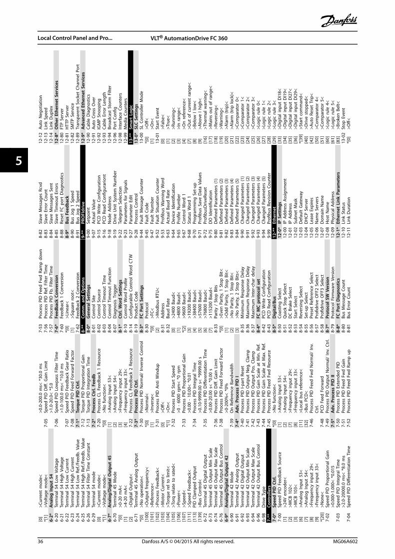
[0]
>Cur
rent
mod
e<*[
1]>V
olta
ge m
ode<
6-2*
Ana
log
Inpu
t 54
6-20
Term
inal
54
Low
Vol
tage
6-21
Term
inal
54
Hig
h V
olta
ge6-
22Te
rmin
al 5
4 Lo
w C
urre
nt6-
23Te
rmin
al 5
4 H
igh
Cur
rent
6-24
Term
inal
54
Low
Ref
./Fee
db. V
alue
6-25
Term
inal
54
Hig
h R
ef./F
eedb
. Val
ue6-
26Te
rmin
al 5
4 Fi
lter
Tim
e Co
nsta
nt6-
29Te
rmin
al 5
4 m
ode
[0]
>Cur
rent
mod
e<*[
1]>V
olta
ge m
ode<
6-7*
Ana
log/
Dig
ital O
utpu
t 45
6-70
Term
inal
45
Mod
e*[
0]>0
-20
mA
<[1
]>4
-20
mA
<[2
]>D
igita
l Out
put<
6-71
Term
inal
45
Ana
log
Out
put
*[0]
>No
ope
ratio
n<[1
00]
>Out
put
freq
uenc
y<[1
01]
>Ref
eren
ce<
[102
]>P
roce
ss F
eedb
ack<
[103
]>M
otor
Cur
rent
<[1
04]
>Tor
que
rel t
o li
mit<
[105
]>T
orq
rela
te t
o r
ated
<[1
06]
>Pow
er<
[107
]>S
peed
<[1
11]
>Spe
ed F
eedb
ack<
[113
]PI
D C
lam
ped
Out
put
[139
]>B
us C
ontr
ol<
6-72
Term
inal
45
Dig
ital O
utpu
t6-
73Te
rmin
al 4
5 O
utpu
t M
in S
cale
6-74
Term
inal
45
Out
put
Max
Sca
le6-
76Te
rmin
al 4
5 O
utpu
t Bu
s Co
ntro
l6-
9*A
nalo
g/D
igita
l Out
put
426-
90Te
rmin
al 4
2 M
ode
6-91
Term
inal
42
Ana
log
Out
put
6-92
Term
inal
42
Dig
ital O
utpu
t6-
93Te
rmin
al 4
2 O
utpu
t M
in S
cale
6-94
Term
inal
42
Out
put
Max
Sca
le6-
96Te
rmin
al 4
2 O
utpu
t Bu
s Co
ntro
l6-
98D
rive
Type
7-**
Cont
rolle
rs7-
0*Sp
eed
PID
Ctr
l.7-
00Sp
eed
PID
Fee
dbac
k So
urce
[1]
>24V
enc
oder
<[2
]>M
CB 1
02<
[3]
>MCB
103
<[6
]>A
nalo
g In
put
53<
[7]
>Ana
log
Inpu
t 54
<[8
]>F
requ
ency
inpu
t 29
<[9
]>F
requ
ency
inpu
t 33
<*[
20]
>Non
e<7-
02Sp
eed
PID
Pro
port
iona
l Gai
n>0
.000
-1.0
00<
*0.
015
7-03
Spee
d P
ID In
tegr
al T
ime
>2.0
-200
00.0
ms<
*8.
0 m
s7-
04Sp
eed
PID
Diff
eren
tiatio
n T
ime
>0.0
-200
.0 m
s< *
30.0
ms
7-05
Spee
d P
ID D
iff. G
ain
Lim
it>1
.0-2
0.0<
*5.
07-
06Sp
eed
PID
Low
pass
Filt
er T
ime
>1.0
-100
.0 m
s< *
10.0
ms
7-07
Spee
d P
ID F
eedb
ack
Gea
r Ra
tio7-
08Sp
eed
PID
Fee
d F
orw
ard
Fac
tor
7-1*
Torq
ue P
ID C
trl.
7-12
Torq
ue P
ID P
ropo
rtio
nal G
ain
7-13
Torq
ue P
ID In
tegr
atio
n T
ime
7-2*
Proc
ess
Ctrl.
Fee
db7-
20Pr
oces
s CL
Fee
dbac
k 1
Reso
urce
*[0]
>No
func
tion<
[1]
>Ana
log
Inpu
t 53
<[2
]>A
nalo
g In
put
54<
[3]
>Fre
quen
cy in
put
29<
[4]
>Fre
quen
cy in
put
33<
7-22
Proc
ess
CL F
eedb
ack
2 Re
sour
ce7-
3*Pr
oces
s PI
D C
trl.
7-30
Proc
ess
PID
Nor
mal
/ In
vers
e Co
ntro
l*[
0]>N
orm
al<
[1]
>Inv
erse
<7-
31Pr
oces
s PI
D A
nti W
indu
p[0
]>O
ff<*[
1]>O
n<7-
32Pr
oces
s PI
D S
tart
Spe
ed>0
- 6
000
rpm
< *
0 rp
m7-
33Pr
oces
s PI
D P
ropo
rtio
nal G
ain
>0.0
0 -
10.0
0< *
0.01
7-34
Proc
ess
PID
Inte
gral
Tim
e>0
.10-
9999
.00
s< *
9999
.00
s7-
35Pr
oces
s PI
D D
iffer
entia
tion
Tim
e>0
.00-
20.0
0 s<
*0.
00 s
7-36
Proc
ess
PID
Diff
. Gai
n L
imit
7-38
Proc
ess
PID
Fee
d F
orw
ard
Fac
tor
>0-2
00%
< *
0%7-
39O
n R
efer
ence
Ban
dwid
th7-
4*A
dv. P
roce
ss P
ID I
7-40
Proc
ess
PID
I-pa
rt R
eset
7-41
Proc
ess
PID
Out
put
Neg
. Cla
mp
7-42
Proc
ess
PID
Out
put
Pos.
Cla
mp
7-43
Proc
ess
PID
Gai
n S
cale
at
Min
. Ref
.7-
44Pr
oces
s PI
D G
ain
Sca
le a
t M
ax. R
ef.
7-45
Proc
ess
PID
Fee
d F
wd
Res
ourc
e*[
0]>N
o fu
nctio
n<[1
]>A
nalo
g In
put
53<
[2]
>Ana
log
Inpu
t 54
<[7
]>F
requ
ency
inpu
t 29
<[8
]>F
requ
ency
inpu
t 33
<[1
1]>L
ocal
bus
ref
eren
ce<
[32]
>Bus
PCD
<7-
46Pr
oces
s PI
D F
eed
Fw
d N
orm
al/
Inv.
Ctrl.
7-48
PCD
Fee
d F
orw
ard
7-49
Proc
ess
PID
Out
put
Nor
mal
/ In
v. C
trl.
7-5*
Adv
. Pro
cess
PID
II7-
50Pr
oces
s PI
D E
xten
ded
PID
7-51
Proc
ess
PID
Fee
d F
wd
Gai
n7-
52Pr
oces
s PI
D F
eed
Fw
d R
amp
up
7-53
Proc
ess
PID
Fee
d F
wd
Ram
p d
own
7-56
Proc
ess
PID
Ref
. Filt
er T
ime
7-57
Proc
ess
PID
Fb.
Filt
er T
ime
7-6*
Feed
back
Con
vers
ion
7-60
Feed
back
1 C
onve
rsio
n*[
0]>L
inea
r<[1
]>S
quar
e ro
ot<
7-62
Feed
back
2 C
onve
rsio
n8-
**Co
mm
. and
Opt
ions
8-0*
Gen
eral
Set
tings
8-01
Cont
rol S
ite8-
02Co
ntro
l Sou
rce
8-03
Cont
rol T
imeo
ut T
ime
8-04
Cont
rol T
imeo
ut F
unct
ion
8-07
Dia
gnos
is T
rigge
r8-
1*Ct
rl. W
ord
Set
tings
8-10
Cont
rol W
ord
Pro
file
8-14
Confi
gura
ble
Cont
rol W
ord
CTW
8-19
Prod
uct
Code
8-3*
FC P
ort
Sett
ings
8-30
Prot
ocol
*[0]
>FC<
[2]
>Mod
bus
RTU
<8-
31Ad
dres
s8-
32Ba
ud R
ate
[0]
>240
0 Ba
ud<
[1]
>480
0 Ba
ud<
*[2]
>960
0 Ba
ud<
[3]
>192
00 B
aud<
[4]
>384
00 B
aud<
[5]
>576
00 B
aud<
[6]
>768
00 B
aud<
[7]
>115
200
Baud
<8-
33Pa
rity
/ St
op B
its*[
0]>E
ven
Par
ity, 1
Sto
p B
it<[1
]>O
dd P
arity
, 1 S
top
Bit<
[2]
>No
Par
ity, 1
Sto
p B
it<[3
]>N
o P
arity
, 2 S
top
Bits
<8-
35M
inim
um R
espo
nse
Del
ay8-
36M
axim
um R
espo
nse
Del
ay8-
37M
axim
um In
ter-
char
del
ay8-
4*FC
MC
pro
toco
l set
8-42
PCD
Writ
e Co
nfigu
ratio
n8-
43PC
D R
ead
Con
figur
atio
n8-
5*D
igita
l/Bus
8-50
Coas
ting
Sel
ect
8-51
Qui
ck S
top
Sel
ect
8-52
DC
Bra
ke S
elec
t8-
53St
art
Sele
ct8-
54Re
vers
ing
Sel
ect
8-55
Set-
up S
elec
t8-
56Pr
eset
Ref
eren
ce S
elec
t8-
57Pr
ofidr
ive
OFF
2 Se
lect
8-58
Profi
driv
e O
FF3
Sele
ct8-
7*Pr
otoc
ol S
W V
ersi
on8-
79Pr
otoc
ol F
irmw
are
Vers
ion
8-8*
FC P
ort
Dia
gnos
tics
8-80
Bus
Mes
sage
Cou
nt8-
81Bu
s Er
ror
Coun
t
8-82
Slav
e M
essa
ges
Rcvd
8-83
Slav
e Er
ror
Coun
t8-
84Sl
ave
Mes
sage
s Se
nt8-
85Sl
ave
Tim
eout
Err
ors
8-88
Rese
t FC
por
t D
iagn
ostic
s8-
9*Bu
s Fe
edba
ck8-
90Bu
s Jo
g 1
Spe
ed8-
91Bu
s Jo
g 2
Spe
ed9-
**PR
OFI
driv
e9-
00Se
tpoi
nt9-
07Ac
tual
Val
ue9-
15PC
D W
rite
Confi
gura
tion
9-16
PCD
Rea
d C
onfig
urar
iont
9-18
Nod
e Ad
dres
s9-
19D
rive
Uni
t Sy
stem
Num
ber
9-22
Tele
gram
Sel
ectio
n9-
23Pa
ram
eter
s fo
r Si
gnal
s9-
27Pa
ram
eter
Edi
t9-
28Pr
oces
s Co
ntro
l9-
44Fa
ult
Mes
sage
Cou
nter
9-45
Faul
t Co
de9-
47Fa
ult
Num
ber
9-52
Faul
t Si
tuat
ion
Cou
nter
9-53
Profi
bus
War
ning
Wor
d9-
63Ac
tual
Bau
d R
ate
9-64
Dev
ice
Iden
tifica
tion
9-65
Profi
le N
umbe
r9-
67Co
ntro
l Wor
d 1
9-68
Stat
us W
ord
19-
70Pr
ogra
mm
ing
Set
-up
9-71
Profi
bus
Save
Dat
a Va
lues
9-72
Profi
busD
riveR
eset
9-75
DO
Iden
tifica
tion
9-80
Defi
ned
Par
amet
ers
(1)
9-81
Defi
ned
Par
amet
ers
(2)
9-82
Defi
ned
Par
amet
ers
(3)
9-83
Defi
ned
Par
amet
ers
(4)
9-84
Defi
ned
Par
amet
ers
(5)
9-90
Chan
ged
Par
amet
ers
(1)
9-91
Chan
ged
Par
amet
ers
(2)
9-92
Chan
ged
Par
amet
ers
(3)
9-93
Chan
ged
Par
amet
ers
(4)
9-94
Chan
ged
Par
amet
ers
(5)
9-99
Profi
bus
Revi
sion
Cou
nter
12-*
*Et
hern
et12
-0*
IP S
ettin
gs12
-00
IP A
ddre
ss A
ssig
nmen
t12
-01
IP A
ddre
ss12
-02
Subn
et M
ask
12-0
3D
efau
lt G
atew
ay12
-04
DH
CP S
erve
r12
-05
Leas
e Ex
pire
s12
-06
Nam
e Se
rver
s12
-07
Dom
ain
Nam
e12
-08
Hos
t N
ame
12-0
9Ph
ysic
al A
ddre
ss12
-1*
Ethe
rnet
Lin
k Pa
ram
eter
s12
-10
Link
Sta
tus
12-1
1Li
nk D
urat
ion
12-1
2Au
to N
egot
iatio
n12
-13
Link
Spe
ed12
-14
Link
Dup
lex
12-8
*O
ther
Eth
erne
t Se
rvic
es12
-80
FTP
Ser
ver
12-8
1H
TTP
Ser
ver
12-8
2SM
TP S
ervi
ce12
-89
Tran
spar
ent
Sock
et C
hann
el P
ort
12-9
*A
dvan
ced
Eth
erne
t Se
rvic
es12
-90
Cabl
e D
iagn
ostic
s12
-91
Auto
Cro
ss O
ver
12-9
2IG
MP
Sno
opin
g12
-93
Cabl
e Er
ror
Leng
th12
-94
Broa
dcas
t St
orm
Filt
er12
-96
Port
Con
fig12
-98
Inte
rfac
e Co
unte
rs12
-99
Med
ia C
ount
ers
13-*
*Sm
art
Logi
c13
-0*
SLC
Set
tings
13-0
0SL
Con
trol
ler
Mod
e*[
0]>O
ff<[1
]>O
n<13
-01
Star
t Ev
ent
[0]
>Fal
se<
[1]
>Tru
e<[2
]>R
unni
ng<
[3]
>In
ran
ge<
[4]
>On
refe
renc
e<[7
]>O
ut o
f cu
rren
t ra
nge<
[8]
>Bel
ow I
low
<[9
]>A
bove
I hi
gh<
[16]
>The
rmal
war
ning
<[1
7]>M
ains
out
of
rang
e<[1
8]>R
ever
sing
<[1
9]>W
arni
ng<
[20]
>Ala
rm (t
rip)<
[21]
>Ala
rm (t
rip lo
ck)<
[22]
>Com
para
tor
0<[2
3]>C
ompa
rato
r 1<
[24]
>Com
para
tor
2<[2
5]>C
ompa
rato
r 3<
[26]
>Log
ic r
ule
0<[2
7]>L
ogic
rul
e 1<
[28]
>Log
ic r
ule
2<[2
9]>L
ogic
rul
e 3<
[33]
>Dig
ital i
nput
DI1
8<[3
4]>D
igita
l inp
ut D
I19<
[35]
>Dig
ital i
nput
DI2
7<[3
6]>D
igita
l inp
ut D
I29<
*[39
]>S
tart
com
man
d<[4
0]>D
rive
stop
ped<
[42]
>Aut
o R
eset
Trip
<[5
0]>C
ompa
rato
r 4<
[51]
>Com
para
tor
5<[6
0]>L
ogic
rul
e 4<
[61]
>Log
ic r
ule
5<[8
3]>B
roke
n B
elt<
13-0
2St
op E
vent
*[0]
>Off<
Local Control Panel and Pro... VLT® AutomationDrive FC 360
36 Danfoss A/S © 04/2015 All rights reserved. MG06A602
55

[1]
>On<
13-0
3Re
set
SLC
*[0]
>Do
not
rese
t SL
C<[1
]>R
eset
SLC
<13
-1*
Com
para
tors
13-1
0Co
mpa
rato
r O
pera
nd13
-11
Com
para
tor
Ope
rato
r13
-12
Com
para
tor
Valu
e13
-2*
Tim
ers
13-2
0SL
Con
trol
ler
Tim
er13
-4*
Logi
c Ru
les
13-4
0Lo
gic
Rule
Boo
lean
113
-41
Logi
c Ru
le O
pera
tor
113
-42
Logi
c Ru
le B
oole
an 2
13-4
3Lo
gic
Rule
Ope
rato
r 2
13-4
4Lo
gic
Rule
Boo
lean
313
-5*
Stat
es13
-51
SL C
ontr
olle
r Ev
ent
13-5
2SL
Con
trol
ler
Actio
n14
-**
Spec
ial F
unct
ions
14-0
*In
vert
er S
witc
hing
14-0
1Sw
itchi
ng F
requ
ency
[0]
>Ran
3<[1
]>R
an5<
[2]
>2.0
kH
z<[3
]>3
.0 k
Hz<
[4]
>4.0
kH
z<*[
5]>5
.0 k
Hz<
[6]
>6.0
kH
z<[7
]>8
.0 k
Hz<
[8]
>10.
0 kH
z<[9
]>1
2.0k
Hz<
[10]
>16.
0kH
z<14
-03
Ove
rmod
ulat
ion
[0]
>Off<
*[1]
>On<
14-0
7D
ead
Tim
e Co
mpe
nsat
ion
Lev
el14
-08
Dam
ping
Gai
n F
acto
r14
-09
Dea
d T
ime
Bias
Cur
rent
Lev
el14
-1*
Mai
ns O
n/O
ff14
-10
Mai
ns F
ailu
re*[
0]>N
o fu
nctio
n<[1
]>C
trl.
ram
p-do
wn<
[2]
>Ctr
l. ra
mp-
dow
n, t
rip<
[3]
>Coa
stin
g<[4
]>K
inet
ic b
ack-
up<
[5]
>Kin
etic
bac
k-up
, trip
<[6
]>A
larm
<[7
]>K
in. b
ack-
up, t
rip w
reco
very
<14
-11
Mai
ns V
olta
ge a
t M
ains
Fau
lt14
-12
Func
tion
at
Mai
ns Im
bala
nce
*[0]
>Trip
<[1
]>W
arni
ng<
[2]
>Dis
able
d<[3
]>D
erat
e<14
-15
Kin.
Bac
kup
Trip
Rec
over
y Le
vel
14-2
*Re
set
Func
tions
14-2
0Re
set
Mod
e*[
0]>M
anua
l res
et<
[1]
>Aut
omat
ic r
eset
x 1
<[2
]>A
utom
atic
res
et x
2<
[3]
>Aut
omat
ic re
set
x 3<
[4]
>Aut
omat
ic re
set
x 4<
[5]
>Aut
omat
ic r
eset
x 5
<[6
]>A
utom
atic
rese
t x
6<[7
]>A
utom
atic
res
et x
7<
[8]
>Aut
omat
ic r
eset
x 8
<[9
]>A
utom
atic
res
et x
9<
[10]
>Aut
omat
ic r
eset
x 1
0<[1
1]>A
utom
atic
rese
t x
15<
[12]
>Aut
omat
ic r
eset
x 2
0<[1
3]>I
nfini
te a
uto
res
et<
[14]
>Res
et a
t po
wer
-up<
14-2
1Au
tom
atic
Res
tart
Tim
e>0
-600
s<
*10
s14
-22
Ope
ratio
n M
ode
*[0]
>Nor
mal
ope
ratio
n<[2
]>I
nitia
lisat
ion<
14-2
4Tr
ip D
elay
at
Curr
ent
Lim
it14
-25
Trip
Del
ay a
t To
rque
Lim
it14
-27
Actio
n A
t In
vert
er F
ault
[0]
>Trip
<*[
1]>W
arni
ng o
r tr
ip a
fter
war
ning
<14
-28
Prod
uctio
n S
ettin
gs14
-29
Serv
ice
Code
14-3
*Cu
rren
t Li
mit
Ctr
l.14
-30
Curr
ent
Lim
Ctr
l, Pr
opor
tiona
l Gai
n14
-31
Curr
ent
Lim
Ctr
l, In
tegr
atio
n T
ime
14-3
2Cu
rren
t Li
m C
trl,
Filte
r Ti
me
14-4
*En
ergy
Opt
imis
ing
14-4
0VT
Lev
el14
-41
AEO
Min
imum
Mag
netis
atio
n>4
0–75
%<
*66
%14
-44
d-ax
is c
urre
nt o
ptim
izat
ion
for
IPM
>0–2
00%
< *
100%
14-5
*En
viro
nmen
t14
-50
RFI F
ilter
14-5
1D
C-Li
nk V
olta
ge C
ompe
nsat
ion
14-5
2Fa
n C
ontr
ol*[
5]>C
onst
ant-
on m
ode<
[6]
>Con
stan
t-off
mod
e<[7
]>O
n-w
hen-
Inve
rter
-is-o
n-el
se-o
ffM
ode<
[8]
>Var
iabl
e-sp
eed
mod
e<14
-55
Out
put
Filte
r14
-6*
Aut
o D
erat
e14
-61
Func
tion
at
Inve
rter
Ove
rload
*[0]
Trip
[1]
Der
ate
14-6
3M
in S
witc
h F
requ
ency
*[2]
>2.0
kH
z<[3
]>3
.0 k
Hz<
[4]
>4.0
kH
z<[5
]>5
.0 k
Hz<
[6]
>6.0
kH
z<[7
]>8
.0 k
Hz<
[8]
>10.
0 kH
z<[9
]>1
2.0
kHz<
[10]
>16.
0 kH
z<14
-64
Dea
d T
ime
Com
pens
atio
n Z
ero
Cur
rent
Leve
l14
-65
Spee
d D
erat
e D
ead
Tim
e Co
mpe
n-sa
tion
14-8
*O
ptio
ns14
-89
Opt
ion
Det
ectio
n14
-9*
Faul
t Se
ttin
gs14
-90
Faul
t Le
vel
15-*
*D
rive
Info
rmat
ion
15-6
1O
ptio
n S
W V
ersi
on15
-62
Opt
ion
Ord
erin
g N
o15
-63
Opt
ion
Ser
ial N
o15
-70
Opt
ion
in S
lot
A15
-71
Slot
A O
ptio
n S
W V
ersi
on15
-0*
Ope
ratin
g D
ata
15-0
0O
pera
ting
hou
rs15
-01
Runn
ing
Hou
rs15
-02
kWh
Cou
nter
15-0
3Po
wer
Up'
s15
-04
Ove
r Te
mp'
s15
-05
Ove
r Vo
lt's
15-0
6Re
set
kWh
Cou
nter
15-0
7Re
set
Runn
ing
Hou
rs C
ount
er15
-3*
Ala
rm L
og15
-30
Ala
rm L
og: E
rror
Cod
e15
-31
Inte
rnal
Faul
tRea
son
15-4
*D
rive
Iden
tifica
tion
15-4
0FC
Typ
e15
-41
Pow
er S
ectio
n15
-42
Volta
ge15
-43
Soft
war
e Ve
rsio
n15
-44
Ord
ered
Typ
eCod
e15
-45
Actu
al T
ypec
ode
Strin
g15
-46
Driv
e O
rder
ing
No
15-4
8LC
P Id
No
15-4
9SW
ID C
ontr
ol C
ard
15-5
0SW
ID P
ower
Car
d15
-51
Driv
e Se
rial N
umbe
r15
-53
Pow
er C
ard
Ser
ial N
umbe
r15
-6*
Opt
ion
Iden
t15
-60
Opt
ion
Mou
nted
15-9
*Pa
ram
eter
Info
15-9
2D
efine
d P
aram
eter
s15
-97
App
licat
ion
Typ
e15
-98
Driv
e Id
entifi
catio
n15
-99
Para
met
er M
etad
ata
16-*
*D
ata
Read
outs
16-0
*G
ener
al S
tatu
s16
-00
Cont
rol W
ord
16-0
1Re
fere
nce
[Uni
t]16
-02
Refe
renc
e [%
]16
-03
Stat
us W
ord
16-0
5M
ain
Act
ual V
alue
[%]
16-0
9Cu
stom
Rea
dout
16-1
*M
otor
Sta
tus
16-1
0Po
wer
[kW
]16
-11
Pow
er [h
p]16
-12
Mot
or V
olta
ge
16-1
3Fr
eque
ncy
16-1
4M
otor
cur
rent
16-1
5Fr
eque
ncy
[%]
16-1
6To
rque
[Nm
]16
-18
Mot
or T
herm
al16
-22
Torq
ue [%
]16
-3*
Dri
ve S
tatu
s16
-30
DC
Lin
k Vo
ltage
16-3
3Br
ake
Ener
gy /
2 m
in16
-34
Hea
tsin
k Te
mp.
16-3
5In
vert
er T
herm
al16
-36
Inv.
Nom
. Cur
rent
16-3
7In
v. M
ax. C
urre
nt16
-38
SL C
ontr
olle
r St
ate
16-3
9Co
ntro
l Car
d T
emp.
16-5
*Re
f. &
Fee
db.
16-5
0Ex
tern
al R
efer
ence
16-5
2Fe
edba
ck[U
nit]
16-5
7Fe
edba
ck [R
PM]
16-6
*In
puts
& O
utpu
ts16
-60
Dig
ital I
nput
16-6
1Te
rmin
al 5
3 Se
ttin
g16
-62
Ana
log
Inpu
t 53
16-6
3Te
rmin
al 5
4 Se
ttin
g16
-64
Ana
log
Inpu
t A
I54
16-6
5A
nalo
g O
utpu
t 42
[mA
]16
-66
Dig
ital O
utpu
t16
-67
Puls
e In
put
29[H
z]16
-68
Puls
e In
put
33 [H
z]16
-69
Puls
e O
utpu
t 27
[Hz]
16-7
0Pu
lse
Out
put
29 [H
z]16
-71
Rela
y O
utpu
t16
-72
Coun
ter
A16
-73
Coun
ter
B16
-79
Ana
log
Out
put
AO45
16-8
*Fi
eldb
us &
FC
Por
t16
-80
Fiel
dbus
CTW
116
-82
Fiel
dbus
REF
116
-84
Com
m. O
ptio
n S
TW16
-85
FC P
ort
CTW
116
-86
FC P
ort
REF
116
-9*
Dia
gnos
is R
eado
uts
16-9
0A
larm
Wor
d16
-91
Ala
rm W
ord
216
-92
War
ning
Wor
d16
-93
War
ning
Wor
d 2
16-9
4Ex
t. S
tatu
s W
ord
16-9
5Ex
t. S
tatu
s W
ord
217
-**
Feed
back
Opt
ions
17-6
0Fe
edba
ck D
irect
ion
17-6
1Fe
edba
ck S
igna
l Mon
itorin
g17
-1*
Inc.
Enc.
Inte
rfac
17-1
0Si
gnal
Typ
e17
-11
Reso
lutio
n (P
PR)
17-5
*Re
solv
er In
terf
ace
17-5
0Po
les
17-5
1In
put
Volta
ge17
-52
Inpu
t Fr
eque
ncy
17-5
3Tr
ansf
orm
atio
n R
atio
17-5
6En
coce
r Si
m. R
esol
utio
n17
-59
Reso
lver
Inte
rfac
e17
-6*
Mon
itori
ng a
nd A
pp.
18-*
*D
ata
Read
outs
218
-9*
PID
Rea
dout
s18
-90
Proc
ess
PID
Err
or18
-91
Proc
ess
PID
Out
put
18-9
2Pr
oces
s PI
D C
lam
ped
Out
put
18-9
3Pr
oces
s PI
D G
ain
Sca
led
Out
put
22-*
*A
ppl.
Func
tions
22-4
*Sl
eep
Mod
e22
-40
Min
imum
Run
Tim
e22
-41
Min
imum
Sle
ep T
ime
22-4
3W
ake-
Up
Spe
ed [H
z]22
-44
Wak
e-U
p R
ef./F
B D
iff22
-45
Setp
oint
Boo
st22
-46
Max
imum
Boo
st T
ime
22-4
7Sl
eep
Spe
ed [H
z]22
-6*
Brok
en B
elt
Det
ectio
n22
-60
Brok
en B
elt
Func
tion
22-6
1Br
oken
Bel
t To
rque
22-6
2Br
oken
Bel
t D
elay
30-*
*Sp
ecia
l Fea
ture
s30
-2*
Adv
. Sta
rt A
djus
t30
-20
Hig
h S
tart
ing
Tor
que
Tim
e [s
]30
-21
Hig
h S
tart
ing
Tor
que
Curr
ent
[%]
30-2
2Lo
cked
Rot
or P
rote
ctio
n30
-23
Lock
ed R
otor
Det
ectio
n T
ime
[s]
32-*
*M
otio
n C
ontr
ol B
asic
Set
tings
32-1
1U
ser
Uni
t D
enom
inat
or32
-12
Use
r U
nit
Num
erat
or32
-67
Max
. Tol
erat
ed P
ositi
on E
rror
32-6
9PI
D S
ampl
e Ti
me
32-8
0M
axim
um A
llow
ed V
eloc
ity32
-81
Mot
ion
Ctr
l Qui
ck S
top
Ram
p33
-**
Mot
ion
Con
trol
Adv
. Set
tings
33-0
0Fo
rce
Hom
e33
-01
Hom
e O
ffset
33-0
2H
ome
Ram
p T
ime
33-0
3H
omin
g V
eloc
ity33
-04
Hom
e Ty
pe33
-41
Neg
ativ
e So
ftw
are
Lim
it33
-42
Posi
tive
Soft
war
e Li
mit
33-4
3N
egat
ive
Soft
war
e Li
mit
Act
ive
33-4
4Po
sitiv
e So
ftw
are
Lim
it A
ctiv
e33
-47
Targ
et P
ositi
on W
indo
w34
-**
Mot
ion
Con
trol
Dat
a Re
adou
ts34
-01
PCD
1 W
rite
For
App
licat
ion
34-0
2PC
D 2
Writ
e Fo
r A
pplic
atio
n34
-03
PCD
3 W
rite
For
App
licat
ion
34-0
4PC
D 4
Writ
e Fo
r A
pplic
atio
n34
-05
PCD
5 W
rite
For
App
licat
ion
34-0
6PC
D 6
Writ
e Fo
r A
pplic
atio
n34
-07
PCD
7 W
rite
For
App
licat
ion
34-0
8PC
D 8
Writ
e Fo
r A
pplic
atio
n34
-09
PCD
9 W
rite
For
App
licat
ion
34-1
0PC
D 1
0 W
rite
For
App
licat
ion
34-2
1PC
D 1
Rea
d F
or A
pplic
atio
n34
-22
PCD
2 R
ead
For
App
licat
ion
Local Control Panel and Pro... Quick Guide
MG06A602 Danfoss A/S © 04/2015 All rights reserved. 37
5 5
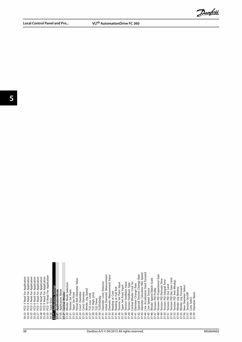
34-2
3PC
D 3
Rea
d F
or A
pplic
atio
n33
-24
PCD
4 R
ead
For
App
licat
ion
33-2
5PC
D 5
Rea
d F
or A
pplic
atio
n33
-26
PCD
6 R
ead
For
App
licat
ion
33-2
7PC
D 7
Rea
d F
or A
pplic
atio
n33
-28
PCD
8 R
ead
For
App
licat
ion
33-2
9PC
D 9
Rea
d F
or A
pplic
atio
n33
-30
PCD
10
Read
For
App
licat
ion
34-5
6Tr
ack
Erro
r37
-**
App
licat
ion
Set
tings
37-0
*A
pplic
atio
nMod
e37
-00
App
licat
ion
Mod
e37
-2*
Cent
ral W
inde
r37
-20
Win
der
Mod
e Se
lect
ion
37-2
1Te
nsio
n S
et P
oint
37-2
2Ta
per
Set
Poin
t37
-23
Part
ial R
oll D
iam
eter
Val
ue37
-24
Core
1 D
iam
eter
37-2
5Co
re2
Dia
met
er37
-26
Win
der
Jog
Spe
ed37
-27
TLD
Low
Lim
it37
-28
TLD
Hig
h L
imit
37-2
9TL
D T
imer
37-3
0TL
DO
nDel
ay37
-31
Dia
met
er L
imit
Det
ecto
r37
-32
Initi
al D
iam
eter
Mea
sure
men
t37
-33
Dia
met
er M
easu
rem
ent
Inpu
t37
-34
Read
ing
at
Core
37-3
5Re
adin
g a
t Fu
ll Ro
ll37
-36
Tens
ion
Set
Poi
nt In
put
37-3
7Ta
per
Set
Poin
t In
put
37-3
8Te
nsio
n F
eedb
ack
Inpu
t37
-39
Tens
ion
Fee
dbac
k Ty
pe37
-40
Cent
ral W
inde
r Cm
d S
rc37
-41
Dia
met
er C
hang
e Ra
te37
-42
Tape
red
Ten
sion
Cha
nge
Rate
37-4
3D
iam
eter
Cal
cula
tor
Min
Spe
ed37
-44
Line
Acc
eler
atio
n F
eed
For
war
d37
-45
Line
Spe
ed S
ourc
e37
-46
Win
der
Spee
d M
atch
Sca
le37
-47
Tens
ion
PID
Pro
file
37-4
8Te
nsio
n P
ID P
ropo
rtio
nal G
ain
37-4
9Te
nsio
n P
ID D
eriv
ate
Tim
e37
-50
Tens
ion
PID
Inte
gral
Tim
e37
-51
Tens
ion
PID
Out
Lim
it37
-52
Tens
ion
PID
Der
Gai
n L
imit
37-5
3Te
nsio
n P
ID A
nti W
indu
p37
-54
Win
der
Jog
Rev
erse
37-5
5W
inde
r Jo
g F
orw
ard
37-5
6N
ew D
iam
eter
Sel
ect
37-5
7Te
nsio
n O
n/O
ff37
-58
Core
Sel
ect
37-5
9D
iam
eter
Res
et
Local Control Panel and Pro... VLT® AutomationDrive FC 360
38 Danfoss A/S © 04/2015 All rights reserved. MG06A602
55

6 Application Examples
6.1.1 AMA
Parameters13
0BE2
03.1
0
FC
+24 V
D IN
D IN
D IN
COM
D IN
D IN
D IN
+10 VA IN
A IN
COM
12
18
19
20
27
29
32
33
50
53
54
55
42A OUT
Function Setting
Parameter 1-29 Automatic MotorAdaptation(AMA)
[1] EnablecompleteAMA
Parameter 5-12 Terminal 27Digital Input
[2]* Coastinverse
*=Default value
Notes/comments: Setparameter group 1-2* MotorData according to motorspecifications.
NOTICEIf terminal 12 and 27 arenot connected, setparameter 5-12 Terminal 27Digital Input to [0] Nooperation.
Table 6.1 AMA with T27 Connected
6.1.2 Speed
Parameters
130B
E204
.10
+24 V
D IN
D IN
D IN
COM
D IN
D IN
D IN
+10 VA IN
A IN
COM
A OUT
12
18
19
20
27
29
32
33
50
53
54
55
420 ~10 V
+
-
FCFunction Setting
Parameter 6-10 Terminal 53 LowVoltage
0.07 V*
Parameter 6-11 Terminal 53 HighVoltage
10 V*
Parameter 6-14 Terminal 53 LowRef./Feedb. Value
0
Parameter 6-15 Terminal 53 HighRef./Feedb. Value
1500
Parameter 6-19 Terminal 53 mode
[1] Voltage
*=Default value
Notes/comments:
Table 6.2 Analog Speed Reference (Voltage)
Parameters
130B
E205
.10
+24 V
D IN
D IN
D IN
COM
D IN
D IN
D IN
+10 VA IN
A IN
COM
A OUT
12
18
19
20
27
29
32
33
50
53
54
55
424 - 20mA
+
-
FCFunction Setting
Parameter 6-12 Terminal 53 LowCurrent
4 mA*
Parameter 6-13 Terminal 53 HighCurrent
20 mA*
Parameter 6-14 Terminal 53 LowRef./Feedb. Value
0
Parameter 6-15 Terminal 53 HighRef./Feedb. Value
1500
Parameter 6-19 Terminal 53 mode
[0] current
*=Default value
Notes/comments:
Table 6.3 Analog Speed Reference (Current)
Parameters13
0BE2
08.1
0
+24 V
D IN
D IN
D IN
COM
D IN
D IN
D IN
+10 VA IN
A IN
COM
A OUT
12
18
19
20
27
29
32
33
50
53
54
55
42
≈ 5kΩ
FCFunction Setting
Parameter 6-10 Terminal 53 LowVoltage
0.07 V*
Parameter 6-11 Terminal 53 HighVoltage
10 V*
Parameter 6-14 Terminal 53 LowRef./Feedb. Value
0
Parameter 6-15 Terminal 53 HighRef./Feedb. Value
1500
Parameter 6-19 Terminal 53 mode
[1] voltage
*=Default value
Notes/comments:
Table 6.4 Speed Reference (Using a Manual Potentiometer)
Application Examples Quick Guide
MG06A602 Danfoss A/S © 04/2015 All rights reserved. 39
6 6
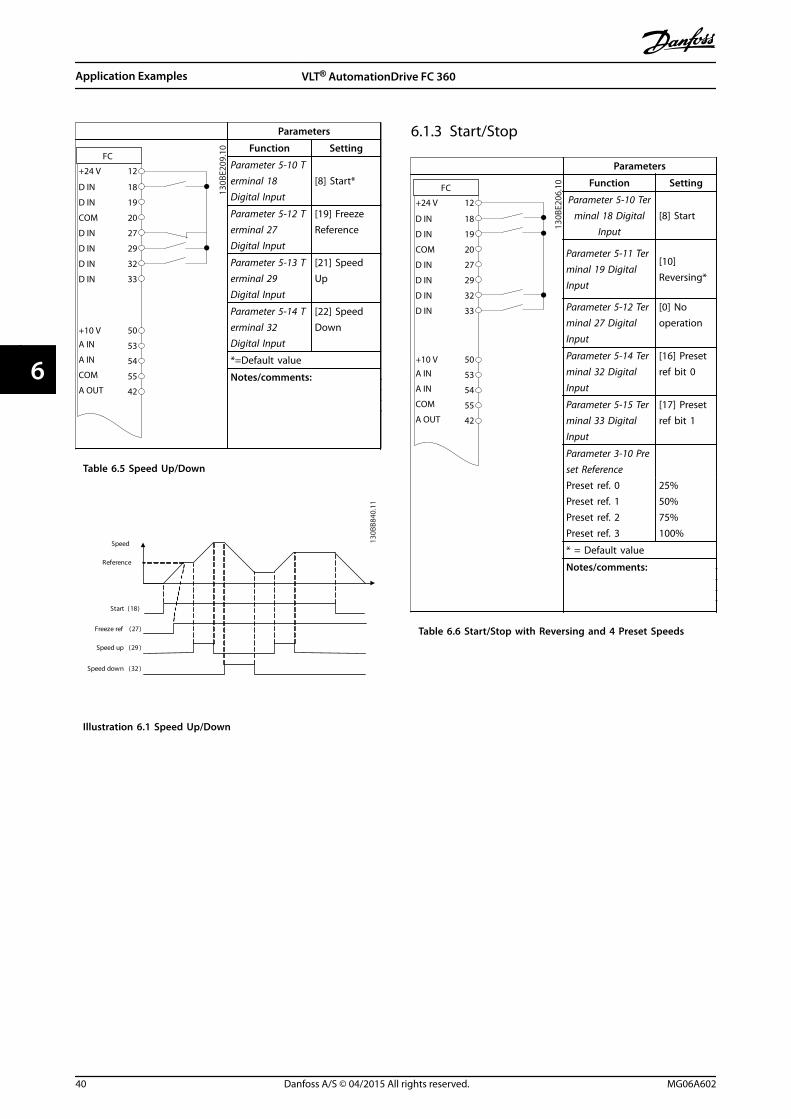
Parameters
FC
+24 V
D IN
D IN
D IN
COM
D IN
D IN
D IN
+10 VA IN
A IN
COM
A OUT
12
18
19
20
27
29
32
33
50
53
54
55
42
130B
E209
.10 Function Setting
Parameter 5-10 Terminal 18Digital Input
[8] Start*
Parameter 5-12 Terminal 27Digital Input
[19] FreezeReference
Parameter 5-13 Terminal 29Digital Input
[21] SpeedUp
Parameter 5-14 Terminal 32Digital Input
[22] SpeedDown
*=Default value
Notes/comments:
Table 6.5 Speed Up/Down
Start (18)
Freeze ref (27)
Speed up (29 )
Speed down (32 )
Speed
Reference
130B
B840
.11
Illustration 6.1 Speed Up/Down
6.1.3 Start/Stop
Parameters
130B
E206
.10
FC
+24 V
D IN
D IN
D IN
COM
D IN
D IN
D IN
+10 VA IN
A IN
COM
A OUT
12
18
19
20
27
29
32
33
50
53
54
55
42
Function Setting
Parameter 5-10 Terminal 18 Digital
Input[8] Start
Parameter 5-11 Terminal 19 DigitalInput
[10]Reversing*
Parameter 5-12 Terminal 27 DigitalInput
[0] Nooperation
Parameter 5-14 Terminal 32 DigitalInput
[16] Presetref bit 0
Parameter 5-15 Terminal 33 DigitalInput
[17] Presetref bit 1
Parameter 3-10 Preset Reference
Preset ref. 0Preset ref. 1Preset ref. 2Preset ref. 3
25%50%75%100%
* = Default value
Notes/comments:
Table 6.6 Start/Stop with Reversing and 4 Preset Speeds
Application Examples VLT® AutomationDrive FC 360
40 Danfoss A/S © 04/2015 All rights reserved. MG06A602
66

6.1.4 External Alarm Reset
Parameters
130B
E207
.10
FC
+24 V
D IN
D IN
D IN
COM
D IN
D IN
D IN
+10 VA IN
A IN
COM
A OUT
12
18
19
20
27
29
32
33
50
53
54
55
42
Function Setting
Parameter 5-11 Terminal 19Digital Input
[1] Reset
*=Default value
Notes/comments:
Table 6.7 External Alarm Reset
6.1.5 Motor Thermistor
NOTICETo meet PELV insulation requirements, use reinforced ordouble insulation on the thermistors.
Parameters
130B
E210
.10
+24 V
D IN
D IN
D IN
COM
D IN
D IN
D IN
+10 VA IN
A IN
COM
A OUT
12
18
19
20
27
29
32
33
50
53
54
55
42
FCFunction Setting
Parameter 1-90 Motor ThermalProtection
[2]Thermistortrip
Parameter 1-93 Thermistor Source
[1] Analoginput 53
Parameter 6-19 Terminal 53 mode [1] Voltage
* = Default value
Notes/comments:If only a warning is needed, setparameter 1-90 Motor ThermalProtection to [1] Thermistorwarning.
Table 6.8 Motor Thermistor
6.1.6 SLC
Parameters
FC
+24 V
D IN
D IN
COM
D IN
D IN
D IN
D IN
+10 VA IN
A IN
COM
A OUTR1
12
18
19
20
27
29
32
33
50
53
54
55
42
01
02
03
130B
E211
.10 Function Setting
Parameter 4-30 Motor FeedbackLoss Function
[1] Warning
Parameter 4-31 Motor FeedbackSpeed Error
100
Parameter 4-32 Motor FeedbackLoss Timeout
5 s
Parameter 7-00 Speed PIDFeedback Source
[2] MCB 102
Parameter 17-11 Resolution (PPR)
1024*
Parameter 13-00 SL ControllerMode
[1] On
Parameter 13-01 Start Event
[19] Warning
Parameter 13-02 Stop Event
[44] Resetkey
Parameter 13-10 ComparatorOperand
[21] Warningno.
Parameter 13-11 ComparatorOperator
[1] ≈*
Parameter 13-12 ComparatorValue
90
Parameter 13-51 SL ControllerEvent
[22]Comparator 0
Parameter 13-52 SL ControllerAction
[32] Setdigital out Alow
Parameter 5-40 Function Relay
[80] SL digitaloutput A
* = Default value
Table 6.9 Using SLC to Set a Relay
Application Examples Quick Guide
MG06A602 Danfoss A/S © 04/2015 All rights reserved. 41
6 6

Notes/comments:If the limit in the feedbackmonitor is exceeded, warning90 feedback monitor is issued.The SLC monitors warning 90feedback monitor. If warning 90feedback monitor becomes true,relay 1 is triggered.External equipment couldindicate that service is required.If the feedback error goesbelow the limit again within 5s, the frequency convertercontinues and the warningdisappears. But relay 1 persistsuntil [Off/Reset] is pressed.
Table 6.10 Using SLC to Set a Relay
Application Examples VLT® AutomationDrive FC 360
42 Danfoss A/S © 04/2015 All rights reserved. MG06A602
66

7 Diagnostics and Troubleshooting
7.1 Warning and Alarm Types
Warning/alarm type
Description
Warning A warning indicates an abnormal operatingcondition that leads to an alarm. A warning stopswhen the abnormal condition is removed.
Alarm An alarm indicates a fault that requiresimmediate attention. The fault always triggers atrip or trip lock. Reset the frequency converterafter an alarm.Reset the frequency converter in any of 4 ways:
• Press [Reset].
• Digital reset input command.
• Serial communication reset input command.
• Auto reset.
TripA trip is an action by the frequency converter to suspendoperation to prevent damages to the frequency converterand other equipment. When a trip occurs, the motor coaststo a stop. The frequency converter logic continues tooperate and monitor the frequency converter status. Afterthe fault condition is remedied, the frequency converter isready for a reset.
Trip lockA trip lock is an action by the frequency converter tosuspend operation to prevent damages to the frequencyconverter and other equipment. When a trip lock occurs,the motor coasts to a stop. The frequency converter logiccontinues to operate and monitor the frequency converterstatus. The frequency converter starts a trip lock only whenserious faults occur that can damage the frequencyconverter or other equipment. After the faults are fixed,cycle the input power before resetting the frequencyconverter.
7.2 Warning and Alarm Displays
Setup 1
Status Quick Menu
MainMenu
130B
D11
1.10
Illustration 7.1 Warning and Alarm Displays
An alarm or trip-lock alarm flashes in the display alongwith the alarm number.
Setup 1
Status Quick Menu
MainMenu
130B
D11
2.10
Illustration 7.2 Alarm/Trip Lock Alarm
In addition to the text and alarm code on the frequencyconverter display, there are 3 status indicator lights. Thewarning indicator light is yellow during an alarm. Thealarm indicator light is red and flashing during an alarm.
130B
D06
2.10
D HandOn Reset
AutoOn
OKOn
Warn
Alarm
Illustration 7.3 Status Indicator Lights
Diagnostics and Troubleshoo... Quick Guide
MG06A602 Danfoss A/S © 04/2015 All rights reserved. 43
7 7
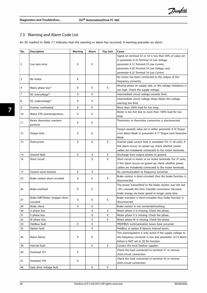
7.3 Warning and Alarm Code List
An (X) marked in Table 7.1 indicates that the warning or alarm has occurred. A warning precedes an alarm.
No. Description Warning Alarm Trip lock Cause
2 Live zero error X X
Signal on terminal 53 or 54 is less than 50% of value setin parameter 6-10 Terminal 53 Low Voltage,parameter 6-12 Terminal 53 Low Current,parameter 6-20 Terminal 54 Low Voltage, andparameter 6-22 Terminal 54 Low Current.
3 No motor X No motor has been connected to the output of the
frequency converter.
4 Mains phase loss1) X X XMissing phase on supply side, or the voltage imbalance istoo high. Check the supply voltage.
7 DC overvoltage1) X X Intermediate circuit voltage exceeds limit.
8 DC undervoltage1) X X Intermediate circuit voltage drops below the voltagewarning low limit.
9 Inverter overloaded X X More than 100% load for too long.
10 Motor ETR overtemperature X X Motor is too hot due to more than 100% load for too
long.
11Motor thermistor overtem-perature
X X Thermistor or thermistor connection is disconnected.
12 Torque limit X X Torque exceeds value set in either parameter 4-16 Torque
Limit Motor Mode or parameter 4-17 Torque Limit GeneratorMode.
13 Overcurrent X X X Inverter peak current limit is exceeded. For J1–J6 units, ifthis alarm occurs on power-up, check whether powercables are mistakenly connected to the motor terminals.
14 Ground fault X X X Discharge from output phases to ground.
16 Short circuit X X Short circuit in motor or on motor terminals. For J7 units,if this alarm occurs on power-up, check whether powercables are mistakenly connected to the motor terminals.
17 Control word timeout X X No communication to frequency converter.
25 Brake resistor short-circuited X X XBrake resistor is short-circuited, thus the brake function isdisconnected.
26 Brake overload X X The power transmitted to the brake resistor over the last120 s exceeds the limit. Possible corrections: Decreasebrake energy via lower speed or longer ramp time.
27Brake IGBT/Brake chopper short-circuited
X X XBrake transistor is short-circuited, thus brake function isdisconnected.
28 Brake check X X Brake resistor is not connected/working.
30 U phase loss X X Motor phase U is missing. Check the phase.
31 V phase loss X X Motor phase V is missing. Check the phase.
32 W phase loss X X Motor phase W is missing. Check the phase.
34 Fieldbus fault X X PROFIBUS communication issues have occurred.
35 Option fault X Fieldbus or option B detects internal errors.
36 Mains failure X X This warning/alarm is only active if the supply voltage to
the frequency converter is lost and parameter 14-10 MainsFailure is NOT set to [0] No Function.
38 Internal fault X X Contact the local Danfoss supplier.
40 Overload T27 X Check the load connected to terminal 27 or remove
short-circuit connection.
41 Overload T29 X Check the load connected to terminal 29 or remove
short-circuit connection.
46 Gate drive voltage fault X X
Diagnostics and Troubleshoo... VLT® AutomationDrive FC 360
44 Danfoss A/S © 04/2015 All rights reserved. MG06A602
77

No. Description Warning Alarm Trip lock Cause
47 24 V supply low X X X 24 V DC may be overloaded.
51 AMA check Unom and Inom X Wrong setting for motor voltage and/or motor current.
52 AMA low Inom X Motor current is too low. Check the settings.
53 AMA big motor X The power size of the motor is too large for the AMA tooperate.
54 AMA small motor X The power size of the motor is too small for the AMA tooperate.
55 AMA parameter range X The parameter values of the motor are outside of the
acceptable range. AMA does not run.
56 AMA interrupt X The AMA is interrupted.
57 AMA timeout X
58 AMA internal X Contact Danfoss.
59 Current limit X X Frequency converter overload.
61 Encoder loss X X
63 Mechanical brake low X Actual motor current has not exceeded release brake-
current within start delay-time window.
65 Control card temp X X X The cut-out temperature of the control card is 80 °C.
67 Option change X A new option is detected or a mounted option isremoved.
69 Power card temp X X X
80 Drive initialised to default value X All parameter settings are initialised to default settings.
87 Auto DC braking X
Occurs in IT mains when the frequency converter coastsand the DC voltage is higher than 830 V. Energy on DC-link is consumed by the motor. This function can beenabled/disabled in parameter 0-07 Auto DC Braking.
88 Option detection X X The option is removed successfully.
90 Feedback monitor X X A feedback fault is detected by option B.
95 Broken belt X X
101 Flow/pressure informationmissing
X X
120 Position control fault X
250 New spare part X X
251 New type code X X
252 Tension limit X
nwrun
Not while running Parameter can only be changed when the motor is
stopped.
Err. A wrong password was entered Occurs when using a wrong password for changing a
password-protected parameter.
Table 7.1 Warnings and Alarms Code List
1) These faults may be caused by mains distortions. Installing a Danfoss line filter may rectify this problem.
For diagnosis, read out the alarm words, warning words, and extended status words.
Diagnostics and Troubleshoo... Quick Guide
MG06A602 Danfoss A/S © 04/2015 All rights reserved. 45
7 7
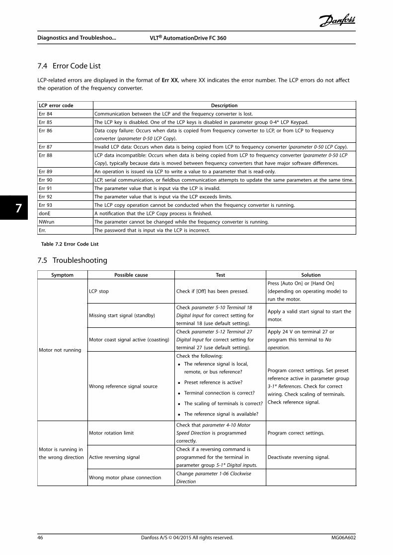
7.4 Error Code List
LCP-related errors are displayed in the format of Err XX, where XX indicates the error number. The LCP errors do not affectthe operation of the frequency converter.
LCP error code Description
Err 84 Communication between the LCP and the frequency converter is lost.
Err 85 The LCP key is disabled. One of the LCP keys is disabled in parameter group 0-4* LCP Keypad.
Err 86 Data copy failure: Occurs when data is copied from frequency converter to LCP, or from LCP to frequencyconverter (parameter 0-50 LCP Copy).
Err 87 Invalid LCP data: Occurs when data is being copied from LCP to frequency converter (parameter 0-50 LCP Copy).
Err 88 LCP data incompatible: Occurs when data is being copied from LCP to frequency converter (parameter 0-50 LCPCopy), typically because data is moved between frequency converters that have major software differences.
Err 89 An operation is issued via LCP to write a value to a parameter that is read-only.
Err 90 LCP, serial communication, or fieldbus communication attempts to update the same parameters at the same time.
Err 91 The parameter value that is input via the LCP is invalid.
Err 92 The parameter value that is input via the LCP exceeds limits.
Err 93 The LCP copy operation cannot be conducted when the frequency converter is running.
donE A notification that the LCP Copy process is finished.
NWrun The parameter cannot be changed while the frequency converter is running.
Err. The password that is input via the LCP is incorrect.
Table 7.2 Error Code List
7.5 Troubleshooting
Symptom Possible cause Test Solution
Motor not running
LCP stop Check if [Off] has been pressed.Press [Auto On] or [Hand On](depending on operating mode) torun the motor.
Missing start signal (standby)Check parameter 5-10 Terminal 18Digital Input for correct setting forterminal 18 (use default setting).
Apply a valid start signal to start themotor.
Motor coast signal active (coasting)Check parameter 5-12 Terminal 27Digital Input for correct setting forterminal 27 (use default setting).
Apply 24 V on terminal 27 orprogram this terminal to Nooperation.
Wrong reference signal source
Check the following:
• The reference signal is local,remote, or bus reference?
• Preset reference is active?
• Terminal connection is correct?
• The scaling of terminals is correct?
• The reference signal is available?
Program correct settings. Set presetreference active in parameter group3-1* References. Check for correctwiring. Check scaling of terminals.Check reference signal.
Motor is running inthe wrong direction
Motor rotation limitCheck that parameter 4-10 MotorSpeed Direction is programmedcorrectly.
Program correct settings.
Active reversing signalCheck if a reversing command isprogrammed for the terminal inparameter group 5-1* Digital inputs.
Deactivate reversing signal.
Wrong motor phase connectionChange parameter 1-06 ClockwiseDirection
Diagnostics and Troubleshoo... VLT® AutomationDrive FC 360
46 Danfoss A/S © 04/2015 All rights reserved. MG06A602
77
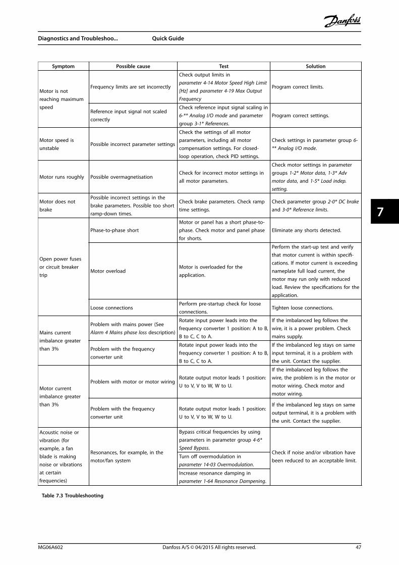
Symptom Possible cause Test Solution
Motor is notreaching maximumspeed
Frequency limits are set incorrectly
Check output limits inparameter 4-14 Motor Speed High Limit[Hz] and parameter 4-19 Max OutputFrequency
Program correct limits.
Reference input signal not scaledcorrectly
Check reference input signal scaling in6-** Analog I/O mode and parametergroup 3-1* References.
Program correct settings.
Motor speed isunstable
Possible incorrect parameter settings
Check the settings of all motorparameters, including all motorcompensation settings. For closed-loop operation, check PID settings.
Check settings in parameter group 6-** Analog I/O mode.
Motor runs roughly Possible overmagnetisationCheck for incorrect motor settings inall motor parameters.
Check motor settings in parametergroups 1-2* Motor data, 1-3* Advmotor data, and 1-5* Load indep.setting.
Motor does notbrake
Possible incorrect settings in thebrake parameters. Possible too shortramp-down times.
Check brake parameters. Check ramptime settings.
Check parameter group 2-0* DC brakeand 3-0* Reference limits.
Open power fusesor circuit breakertrip
Phase-to-phase shortMotor or panel has a short phase-to-phase. Check motor and panel phasefor shorts.
Eliminate any shorts detected.
Motor overloadMotor is overloaded for theapplication.
Perform the start-up test and verifythat motor current is within specifi-cations. If motor current is exceedingnameplate full load current, themotor may run only with reducedload. Review the specifications for theapplication.
Loose connectionsPerform pre-startup check for looseconnections.
Tighten loose connections.
Mains currentimbalance greaterthan 3%
Problem with mains power (SeeAlarm 4 Mains phase loss description)
Rotate input power leads into thefrequency converter 1 position: A to B,B to C, C to A.
If the imbalanced leg follows thewire, it is a power problem. Checkmains supply.
Problem with the frequencyconverter unit
Rotate input power leads into thefrequency converter 1 position: A to B,B to C, C to A.
If the imbalanced leg stays on sameinput terminal, it is a problem withthe unit. Contact the supplier.
Motor currentimbalance greaterthan 3%
Problem with motor or motor wiringRotate output motor leads 1 position:U to V, V to W, W to U.
If the imbalanced leg follows thewire, the problem is in the motor ormotor wiring. Check motor andmotor wiring.
Problem with the frequencyconverter unit
Rotate output motor leads 1 position:U to V, V to W, W to U.
If the imbalanced leg stays on sameoutput terminal, it is a problem withthe unit. Contact the supplier.
Acoustic noise orvibration (forexample, a fanblade is makingnoise or vibrationsat certainfrequencies)
Resonances, for example, in themotor/fan system
Bypass critical frequencies by usingparameters in parameter group 4-6*Speed Bypass.
Check if noise and/or vibration havebeen reduced to an acceptable limit.
Turn off overmodulation inparameter 14-03 Overmodulation.
Increase resonance damping inparameter 1-64 Resonance Dampening.
Table 7.3 Troubleshooting
Diagnostics and Troubleshoo... Quick Guide
MG06A602 Danfoss A/S © 04/2015 All rights reserved. 47
7 7
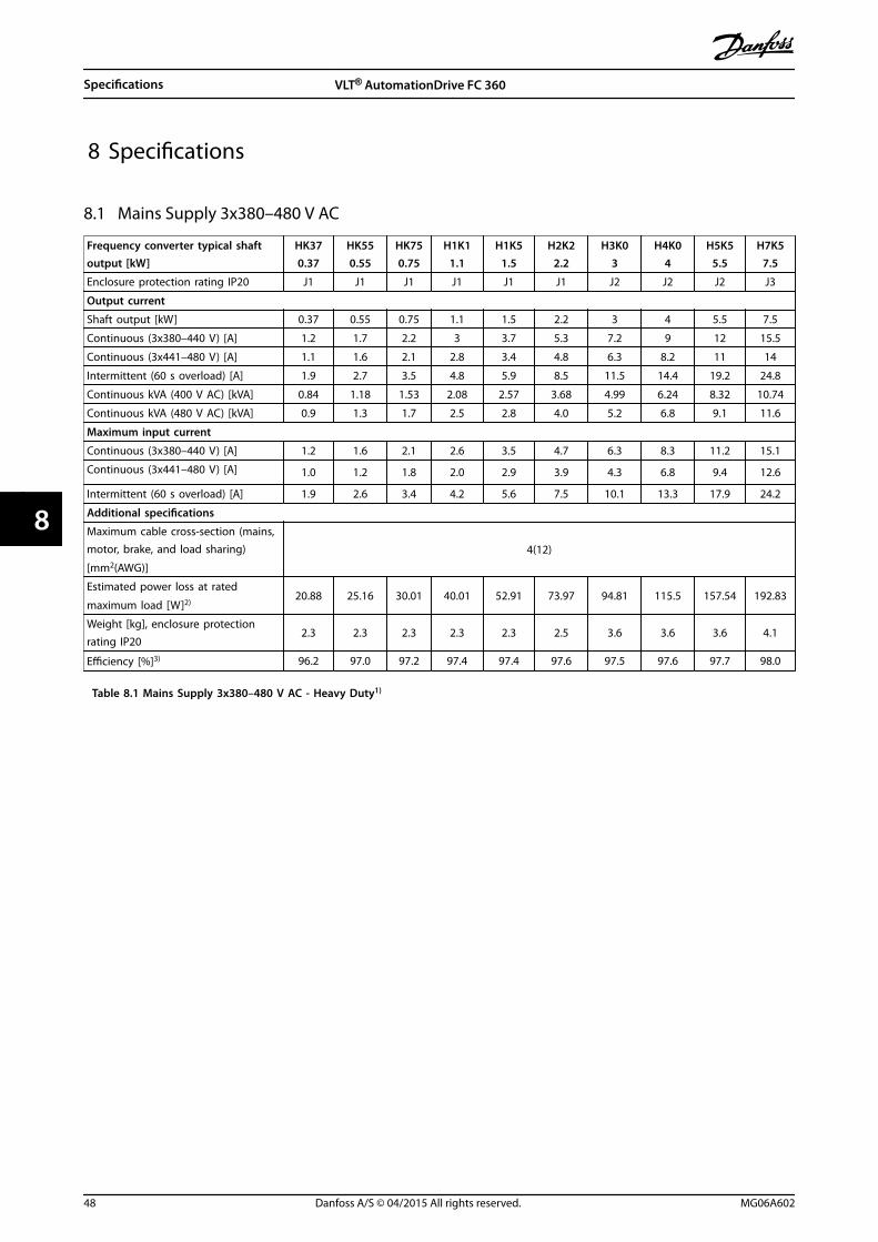
8 Specifications
8.1 Mains Supply 3x380–480 V AC
Frequency converter typical shaftoutput [kW]
HK370.37
HK550.55
HK750.75
H1K11.1
H1K51.5
H2K22.2
H3K03
H4K04
H5K55.5
H7K57.5
Enclosure protection rating IP20 J1 J1 J1 J1 J1 J1 J2 J2 J2 J3
Output current
Shaft output [kW] 0.37 0.55 0.75 1.1 1.5 2.2 3 4 5.5 7.5
Continuous (3x380–440 V) [A] 1.2 1.7 2.2 3 3.7 5.3 7.2 9 12 15.5
Continuous (3x441–480 V) [A] 1.1 1.6 2.1 2.8 3.4 4.8 6.3 8.2 11 14
Intermittent (60 s overload) [A] 1.9 2.7 3.5 4.8 5.9 8.5 11.5 14.4 19.2 24.8
Continuous kVA (400 V AC) [kVA] 0.84 1.18 1.53 2.08 2.57 3.68 4.99 6.24 8.32 10.74
Continuous kVA (480 V AC) [kVA] 0.9 1.3 1.7 2.5 2.8 4.0 5.2 6.8 9.1 11.6
Maximum input current
Continuous (3x380–440 V) [A] 1.2 1.6 2.1 2.6 3.5 4.7 6.3 8.3 11.2 15.1
Continuous (3x441–480 V) [A] 1.0 1.2 1.8 2.0 2.9 3.9 4.3 6.8 9.4 12.6
Intermittent (60 s overload) [A] 1.9 2.6 3.4 4.2 5.6 7.5 10.1 13.3 17.9 24.2
Additional specifications
Maximum cable cross-section (mains,motor, brake, and load sharing)
[mm2(AWG)]
4(12)
Estimated power loss at rated
maximum load [W]2)20.88 25.16 30.01 40.01 52.91 73.97 94.81 115.5 157.54 192.83
Weight [kg], enclosure protectionrating IP20
2.3 2.3 2.3 2.3 2.3 2.5 3.6 3.6 3.6 4.1
Efficiency [%]3) 96.2 97.0 97.2 97.4 97.4 97.6 97.5 97.6 97.7 98.0
Table 8.1 Mains Supply 3x380–480 V AC - Heavy Duty1)
Specifications VLT® AutomationDrive FC 360
48 Danfoss A/S © 04/2015 All rights reserved. MG06A602
88

Frequency converter typicalshaft output [kW]
H11K11
H15K15
H18K18.5
H22K22
H30K30
H37K37
H45K45
H55K55
H75K75
Enclosure protection ratingIP20
J4 J4 J5 J5 J6 J6 J6 J7 J7
Output current
Continuous (3x380–440 V) [A] 23 31 37 42.5 61 73 90 106 147
Continuous (3x441–480 V) [A] 21 27 34 40 52 65 77 96 124
Intermittent (60 s overload) [A] 34.5 46.5 55.5 63.8 91.5 109.5 135 159 220.5
Continuous kVA (400 V AC)[kVA]
15.94 21.48 25.64 29.45 42.3 50.6 62.4 73.4 101.8
Continuous kVA (480 V AC)[kVA]
17.5 22.4 28.3 33.3 43.2 54.0 64.0 79.8 103.1
Maximum input current
Continuous (3x380–440 V) [A] 22.1 29.9 35.2 41.5 57 70.3 84.2 102.9 140.3
Continuous (3x441–480 V) [A] 18.4 24.7 29.3 34.6 49.3 60.8 72.7 88.8 121.1
Intermittent (60 s overload) [A] 33.2 44.9 52.8 62.3 85.5 105.5 126.3 154.4 210.5
Additional specifications
Maximum cable size (mains,
motor, brake) [mm2(AWG)]16(6) 50(1/0) 85(3/0)
Estimated power loss at rated
maximum load [W]2)289.53 393.36 402.83 467.52 630 848 1175 1250 1507
Weight [kg], enclosureprotection rating IP20
9.4 9.5 12.3 12.5 22.4 22.5 22.6 37.3 38.7
Efficiency [%]3) 97.8 97.8 98.1 97.9 98.1 98.0 97.7 98.0 98.2
Table 8.2 Mains Supply 3x380–480 V AC - Heavy Duty1)
Specifications Quick Guide
MG06A602 Danfoss A/S © 04/2015 All rights reserved. 49
8 8

Frequency converter typicalshaft output [kW]
Q11K11
Q15K15
Q18K18.5
Q22K22
Q30K30
Q37K37
Q45K45
Q55K55
Q75K75
Enclosure protection ratingIP20
J4 J4 J5 J5 J6 J6 J6 J7 J7
Output current
Continuous (3x380–440 V)[A]
23 31 37 42.5 61 73 90 106 147
Continuous (3x441–480 V)[A]
21 27 34 40 52 65 77 96 124
Intermittent (60 s overload)[A]
25.3 34.1 40.7 46.8 67.1 80.3 99 116.6 161.7
Continuous kVA (400 V AC)[kVA]
15.94 21.48 25.64 29.45 42.3 50.6 62.4 73.4 101.8
Continuous kVA (480 V AC)[kVA]
17.5 22.4 28.3 33.3 43.2 54.0 64.0 79.8 103.1
Maximum input current
Continuous (3x380–440 V)[A]
22.1 29.9 35.2 41.5 57 70.3 84.2 102.9 140.3
Continuous (3x441–480 V)[A]
18.4 24.7 29.3 34.6 49.3 60.8 72.7 88.8 121.1
Intermittent (60 s overload)[A]
24.3 32.9 38.7 45.7 62.7 77.3 92.6 113.2 154.3
Additional specifications
Maximum cable size (mains,
motor, brake) [mm2(AWG)]16(6) 50(1/0) 85(3/0)
Estimated power loss at
rated maximum load [W]2)289.53 393.36 402.83 467.52 630 848 1175 1250 1507
Weight [kg], enclosureprotection rating IP20
9.4 9.5 12.3 12.5 22.4 22.5 22.6 37.3 38.7
Efficiency [%]3) 97.8 97.8 98.1 97.9 98.1 98.0 97.7 98.0 98.2
Table 8.3 Mains Supply 3x380–480 V AC - Normal Duty1)
1) Heavy duty=150–160% current during 60 s, Normal duty=110% current during 60 s.
2) The typical power loss is at nominal load conditions and expected to be within ±15% (tolerance relates to variety in voltage andcable conditions).Values are based on a typical motor efficiency (IE2/IE3 border line). Motors with lower efficiency add to the power loss in the frequencyconverter and motors with high efficiency reduce power loss.Applies for dimensioning of frequency converter cooling. If the switching frequency is higher than the default setting, the power lossesmay rise. LCP and typical control card power consumptions are included. Further options and customer load may add up to 30 W to thelosses (though typical only 4 W extra for a fully loaded control card, fieldbus, or options for slot B).For power loss data according to EN 50598-2, refer to www.danfoss.com/vltenergyefficiency.
3) Measured using 5 m screened motor cables at rated load and rated frequency for enclosure sizes J1–J5, and using 33 m screenedmotor cables at rated load and rated frequency for enclosure sizes J6 and J7. For energy efficiency class, see the Ambient Conditionssection in chapter 8.2 General Technical Data. For part load losses, see www.danfoss.com/vltenergyefficiency.
Specifications VLT® AutomationDrive FC 360
50 Danfoss A/S © 04/2015 All rights reserved. MG06A602
88

8.2 General Technical Data
Mains supply (L1, L2, L3)Supply terminals L1, L2, L3Supply voltage 380–480 V: -15% (-25%)1) to +10%
1) The frequency converter can run at -25% input voltage with reduced performance. The maximum output power of thefrequency converter is 75% in case of -25% input voltage and 85% in case of -15% input voltage.Full torque cannot be expected at mains voltage lower than 10% below the lowest rated supply voltage of the frequencyconverter.
Supply frequency 50/60 Hz ±5%Maximum imbalance temporary between mains phases 3.0% of rated supply voltageTrue power factor (λ) ≥0.9 nominal at rated loadDisplacement power factor (cos ϕ) near unity (>0.98)Switching on input supply L1, L2, L3 (power-ups) ≤7.5 kW Maximum 2 times/minuteSwitching on input supply L1, L2, L3 (power-ups) 11–75 kW Maximum 1 time/minute
The unit is suitable for use on a circuit capable of delivering less than 100000 RMS symmetrical Amperes, 480 V maximum.
Motor output (U, V, W)Output voltage 0–100% of supply voltageOutput frequency 0–500 HzOutput frequency in VVC+ Mode 0–200 HzSwitching on output UnlimitedRamp time 0.05–3600 s
Torque characteristicsStarting torque (constant torque) Maximum 160% for 60 s1)
Overload torque (constant torque) Maximum 160% for 60 s1)
Starting torque (variable torque) Maximum 110% for 60 s1)
Overload torque (variable torque) Maximum 110% for 60 sStarting current Maximum 200% for 1 sTorque rise time in VVC+ (independent of fsw) 10 ms
1) Percentage relates to the nominal torque.2) The torque response time depends on application and load, but generally, the torque step from 0 to reference is 4–5 x torquerise time.
Cable lengths and cross-sections1)
Maximum motor cable length, screened 50 mMaximum motor cable length, unscreened 0.37–22 kW: 75 m, 30–75 kW: 100 mMaximum cross-section to control terminals, flexible/rigid wire 2.5 mm2/14 AWGMinimum cross-section to control terminals 0.55 mm2/30 AWG
1) For power cables, see Table 8.1 to Table 8.3.
Specifications Quick Guide
MG06A602 Danfoss A/S © 04/2015 All rights reserved. 51
8 8

Digital inputsProgrammable digital inputs 7Terminal number 18, 19, 271), 291), 32, 33, 31Logic PNP or NPNVoltage level 0–24 V DC Voltage level, logic 0 PNP < 5 V DCVoltage level, logic 1 PNP > 10 V DCVoltage level, logic 0 NPN > 19 V DCVoltage level, logic 1 NPN < 14 V DCMaximum voltage on input 28 V DCPulse frequency range 4 Hz–32 kHz(Duty cycle) minimum pulse width 4.5 msInput resistance, Ri approximately 4 kΩ
1) Terminals 27 and 29 can also be programmed as output.
Analog inputsNumber of analog inputs 2Terminal number 53, 54Modes Voltage or currentMode select softwareVoltage level 0–10 VInput resistance, Ri approximately 10 kΩMaximum voltage -15 to +20 VCurrent level 0/4 to 20 mA (scaleable)Input resistance, Ri approximately 200 ΩMaximum current 30 mAResolution for analog inputs 11 bitAccuracy of analog inputs Maximum error 0.5% of full scaleBandwidth 100 Hz
The analog inputs are galvanically isolated from the supply voltage (PELV) and other high-voltage terminals.
Mains
Functionalisolation
PELV isolation
Motor
DC Bus
Highvoltage
Control+24 V
RS-485
18
31
130B
D31
0.10
Illustration 8.1 Analog Inputs
Pulse inputsProgrammable pulse inputs 2Terminal number pulse 29, 33Maximum frequency at terminal 29, 33 32 kHz (push-pull driven)Maximum frequency at terminal 29, 33 5 kHz (open collector)Minimum frequency at terminal 29, 33 4 HzVoltage level see section on digital inputMaximum voltage on input 28 V DCInput resistance, Ri approximately 4 kΩPulse input accuracy (0.1–1 kHz) Maximum error: 0.1% of full scalePulse input accuracy (1–32 kHz) Maximum error: 0.05% of full scale
Specifications VLT® AutomationDrive FC 360
52 Danfoss A/S © 04/2015 All rights reserved. MG06A602
88

Analog outputsNumber of programmable analog outputs 2Terminal number 45, 42Current range at analog output 0/4–20 mAMaximum resistor load to common at analog output 500 ΩAccuracy on analog output Maximum error: 0.8% of full scaleResolution on analog output 10 bit
The analog output is galvanically isolated from the supply voltage (PELV) and other high-voltage terminals.
Control card, RS485 serial communicationTerminal number 68 (P,TX+, RX+), 69 (N,TX-, RX-)Terminal number 61 Common for terminals 68 and 69
The RS485 serial communication circuit is galvanically isolated from the supply voltage (PELV).
Digital outputsProgrammable digital/pulse outputs 2Terminal number 27, 291)
Voltage level at digital/frequency output 0–24 VMaximum output current (sink or source) 40 mAMaximum load at frequency output 1 kΩMaximum capacitive load at frequency output 10 nFMinimum output frequency at frequency output 4 HzMaximum output frequency at frequency output 32 kHzAccuracy of frequency output Maximum error: 0.1% of full scaleResolution of frequency output 10 bit
1) Terminal 27 and 29 can also be programmed as input.
The digital output is galvanically isolated from the supply voltage (PELV) and other high-voltage terminals.
Control card, 24 V DC outputTerminal number 12Maximum load 100 mA
The 24 V DC supply is galvanically isolated from the supply voltage (PELV), but has the same potential as the analog and digitalinputs and outputs.
Relay outputsProgrammable relay outputs 2Relay 01 01–03 (NC), 01–02 (NO), 04–06 (NC), 04–05 (NO)Maximum terminal load (AC-1)1) on 01–02/04–05 (NO) (Resistive load) 250 V AC, 3 AMaximum terminal load (AC-15)1) on 01–02/04–05 (NO) (Inductive load @ cosφ 0.4) 250 V AC, 0.2 AMaximum terminal load (DC-1)1) on 01–02/04–05 (NO) (Resistive load) 30 V DC, 2 AMaximum terminal load (DC-13)1) on 01–02/04–05 (NO) (Inductive load) 24 V DC, 0.1 AMaximum terminal load (AC-1)1) on 01–03/04–06 (NC) (Resistive load) 250 V AC, 3 AMaximum terminal load (AC-15)1)on 01–03/04–06 (NC) (Inductive load @ cosφ 0.4) 250 V AC, 0.2 AMaximum terminal load (DC-1)1) on 01–03/04–06 (NC) (Resistive load) 30 V DC, 2 AMinimum terminal load on 01–03 (NC), 01–02 (NO) 24 V DC 10 mA, 24 V AC 20 mA
1) IEC 60947 t 4 and 5The relay contacts are galvanically isolated from the rest of the circuit by reinforced isolation.
Control card, +10 V DC outputTerminal number 50Output voltage 10.5 V ±0.5 VMaximum load 15 mA
The 10 V DC supply is galvanically isolated from the supply voltage (PELV) and other high-voltage terminals.
Specifications Quick Guide
MG06A602 Danfoss A/S © 04/2015 All rights reserved. 53
8 8

Control characteristicsResolution of output frequency at 0–500 Hz ±0.003 HzSystem response time (terminals 18, 19, 27, 29, 32, and 33) ≤2 msSpeed control range (open loop) 1:100 of synchronous speedSpeed accuracy (open loop) ±0.5% of nominal speedSpeed accuracy (closed loop) ±0.1% of nominal speed
All control characteristics are based on a 4-pole asynchronous motor.
Ambient ConditionsEnclosure sizes J1–J7 IP20Vibration test, all enclosure sizes 1.0 gRelative humidity 5–95% (IEC 721-3-3; Class 3K3 (non-condensing) during operationAggressive environment (IEC 60068-2-43) H2S test Class KdTest method according to IEC 60068-2-43 H2S (10 days)Ambient temperature (at 60 AVM switching mode)- with derating Maximum 55 °C1)
- at full continuous output current with some power size Maximum 50 °C- at full continuous output current Maximum 45 °CMinimum ambient temperature during full-scale operation 0 °CMinimum ambient temperature at reduced performance -10 °CTemperature during storage/transport -25 to +65/70 °CMaximum altitude above sea level without derating 1000 mMaximum altitude above sea level with derating 3000 m
EMC standards, emissionEN 61800-3, EN 61000-3-2, EN 61000-3-3, EN 61000-3-11,
EN 61000-3-12, EN 61000-6-3/4, EN 55011, IEC 61800-3
EMC standards, immunityEN 61800-3, EN 61000-6-1/2, EN 61000-4-2,
EN 61000-4-3, EN 61000-4-4, EN 61000-4-5, EN 61000-4-6Energy efficiency class1) IE2
1) Determined according to EN 50598-2 at:
• Rated load.
• 90% rated frequency.
• Switching frequency factory setting.
• Switching pattern factory setting.
Control card performanceScan interval 1 ms
Protection and features• Electronic thermal motor protection against overload.
• Temperature monitoring of the heat sink ensures that the frequency converter trips when the temperature reachesa predefined level. An overload temperature cannot be reset until the temperature of the heat sink is below thetemperature limit.
• The frequency converter is protected against short circuits on motor terminals U, V, W.
• If a mains phase is missing, the frequency converter trips or issues a warning (depending on the load andparameter setting).
• Monitoring of the intermediate circuit voltage ensures that the frequency converter trips when the intermediatecircuit voltage is too low or too high.
• The frequency converter is protected against ground faults on motor terminals U, V, W.
Specifications VLT® AutomationDrive FC 360
54 Danfoss A/S © 04/2015 All rights reserved. MG06A602
88
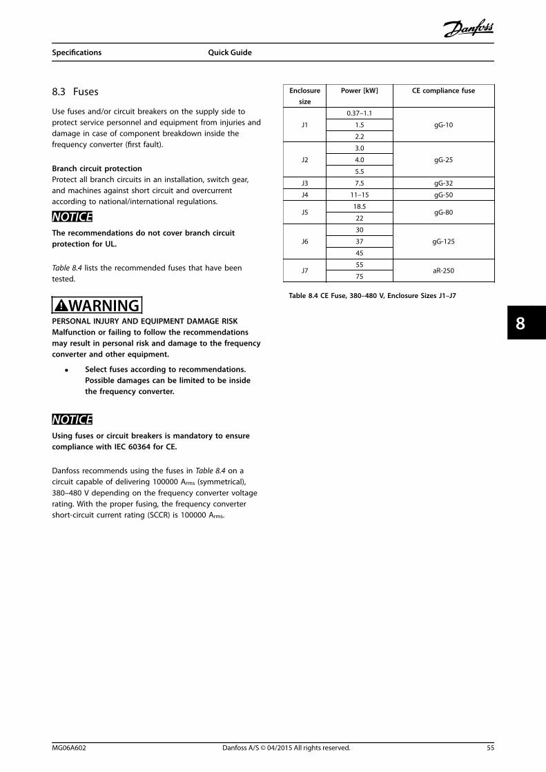
8.3 Fuses
Use fuses and/or circuit breakers on the supply side toprotect service personnel and equipment from injuries anddamage in case of component breakdown inside thefrequency converter (first fault).
Branch circuit protectionProtect all branch circuits in an installation, switch gear,and machines against short circuit and overcurrentaccording to national/international regulations.
NOTICEThe recommendations do not cover branch circuitprotection for UL.
Table 8.4 lists the recommended fuses that have beentested.
WARNINGPERSONAL INJURY AND EQUIPMENT DAMAGE RISKMalfunction or failing to follow the recommendationsmay result in personal risk and damage to the frequencyconverter and other equipment.
• Select fuses according to recommendations.Possible damages can be limited to be insidethe frequency converter.
NOTICEUsing fuses or circuit breakers is mandatory to ensurecompliance with IEC 60364 for CE.
Danfoss recommends using the fuses in Table 8.4 on acircuit capable of delivering 100000 Arms (symmetrical),380–480 V depending on the frequency converter voltagerating. With the proper fusing, the frequency convertershort-circuit current rating (SCCR) is 100000 Arms.
Enclosuresize
Power [kW] CE compliance fuse
J1
0.37–1.1
gG-101.5
2.2
J2
3.0
gG-254.0
5.5
J3 7.5 gG-32
J4 11–15 gG-50
J518.5
gG-8022
J6
30
gG-12537
45
J755
aR-25075
Table 8.4 CE Fuse, 380–480 V, Enclosure Sizes J1–J7
Specifications Quick Guide
MG06A602 Danfoss A/S © 04/2015 All rights reserved. 55
8 8

8.4 Connection Tightening Torques
Make sure to use the right torques when tightening all electrical connections. Too low or too high torque may causeelectrical connection problems. Use a torque wrench to ensure that correct torques are applied.
Enclosuresize
Power [kW]Torque [Nm]
Mains Motor DC connection Brake Ground Relay
J1 0.37–2.2 0.8 0.8 0.8 0.8 3 0.5
J2 3.0–5.5 0.8 0.8 0.8 0.8 3 0.5
J3 7.5 0.8 0.8 0.8 0.8 3 0.5
J4 11–15 1.2 1.2 1.2 1.2 1.6 0.5
J5 18.5–22 1.2 1.2 1.2 1.2 1.6 0.5
J6 30–45 3.5 3.5 3.5 – 2.5 0.5
J7 55 12 12 12 – 2.5 0.5
J7 75 14 14 14 – 2.5 0.5
Table 8.5 Tightening Torques
Specifications VLT® AutomationDrive FC 360
56 Danfoss A/S © 04/2015 All rights reserved. MG06A602
88

Index
AAC waveform............................................................................................ 3
AMA with T27 connected.................................................................. 39
Ambient condition............................................................................... 54
Analog input.......................................................................................... 52
Analog output....................................................................................... 53
Application example........................................................................... 39
Approval..................................................................................................... 3
Automatic motor adaptation........................................................... 14
BBranch circuit protection................................................................... 55
CCable length........................................................................................... 51
Clearance requirement....................................................................... 15
Control cable.......................................................................................... 21
Control card+10 V DC output............................................................................... 53Performance...................................................................................... 54RS485 serial communication....................................................... 53
Control characteristic.......................................................................... 54
Control system......................................................................................... 3
Control terminal.................................................................................... 45
Control wiring........................................................................................ 18
Cross-section.......................................................................................... 51
DDerating............................................................................................ 15, 54
Digital input..................................................................................... 14, 52
Digital output......................................................................................... 53
Discharge time......................................................................................... 7
EElectrical noise....................................................................................... 18
EMC............................................................................................................ 54
Energy efficiency..................................................................... 48, 49, 50
Energy efficiency class........................................................................ 54
External controller.................................................................................. 3
External interlock.................................................................................. 14
FFloating delta......................................................................................... 19
Fuse............................................................................................................ 55
GGround connection.............................................................................. 18
Ground loop........................................................................................... 21
Ground wire............................................................................................ 18
Grounded delta..................................................................................... 19
Grounding........................................................................................ 18, 19
HHigh altitude............................................................................................. 8
High voltage............................................................................................. 7
IIEC 61800-3...................................................................................... 19, 54
Induced voltage.................................................................................... 18
Input power............................................................................................ 18
Input signal............................................................................................. 21
Installation.............................................................................................. 15
Isolated mains........................................................................................ 19
LLeakage current....................................................................................... 8
Load sharing............................................................................................. 7
MMain menu.............................................................................................. 25
Mains supply (L1, L2, L3).................................................................... 51
Mains supply data................................................................................ 48
Menu key................................................................................................. 23
Motorcable..................................................................................................... 18current.................................................................................................. 14data....................................................................................................... 14output.................................................................................................. 51power................................................................................................... 18protection.................................................................................... 18, 54status....................................................................................................... 3wiring................................................................................................... 18
Multiple frequency converters........................................................ 18
NNavigation key....................................................................................... 23
Noise isolation....................................................................................... 18
Numeric display.................................................................................... 23
OOpen loop............................................................................................... 54
Operation key........................................................................................ 23
Optional equipment....................................................................... 3, 19
Index Quick Guide
MG06A602 Danfoss A/S © 04/2015 All rights reserved. 57

Output current...................................................................................... 53
Overload protection............................................................................ 18
PPELV................................................................................................ 8, 41, 53
Power connection................................................................................ 18
Power factor........................................................................................... 19
PROFIBUS................................................................................................. 31
Programming......................................................................................... 14
Protection and feature........................................................................ 54
Pulse input.............................................................................................. 52
QQualified personnel................................................................................ 7
Quick menu............................................................................................ 27
RRelay output........................................................................................... 53
Remote command.................................................................................. 3
Reset................................................................................................... 43, 54
RFI filter.................................................................................................... 19
SSafety........................................................................................................... 8
Screened control cable....................................................................... 21
Serial communication...................................................... 3, 21, 22, 43
Shielded cable....................................................................................... 18
Specification.................................................................................... 15, 22
Specifications......................................................................................... 48
Speed reference.................................................................................... 39
Supply voltage....................................................................................... 53
System feedback..................................................................................... 3
TTechnical data........................................................................................ 51
Terminal programming...................................................................... 21
Terminal tightening torque.............................................................. 56
Thermistor............................................................................................... 41
Torque characteristic........................................................................... 51
Trip function........................................................................................... 18
Troubleshooting................................................................................... 43
UUnintended start..................................................................................... 7
VVoltage level........................................................................................... 52
WWarning and alarm list........................................................................ 45
Wire size................................................................................................... 18
Index VLT® AutomationDrive FC 360
58 Danfoss A/S © 04/2015 All rights reserved. MG06A602

Index Quick Guide
MG06A602 Danfoss A/S © 04/2015 All rights reserved. 59

Danfoss can accept no responsibility for possible errors in catalogues, brochures and other printed material. Danfoss reserves the right to alter its products without notice. This also applies toproducts already on order provided that such alterations can be made without subsequential changes being necessary in specifications already agreed. All trademarks in this material are propertyof the respective companies. Danfoss and the Danfoss logotype are trademarks of Danfoss A/S. All rights reserved.
Danfoss A/SUlsnaes 1DK-6300 Graastenvlt-drives.danfoss.com
*MG06A602*130R0413 MG06A602 04/2015