quick installation guide - climate.emerson.com · 3 wireless remote kit installation quick...
TRANSCRIPT
1
1F85RF-275Wireless Remote Kit
IMPORTANTDo not apply power to the thermostat or wirelesssensor until instructed to do so.
For proper operation of the RF wirelesscommunication, when installing:
Avoid locating thermostat or sensor near anywireless or noise generating devices, particularlyradio devices that operate in the range of 418 to428 MHz.
Be sure that there are no electrical wires, metalpipes or ductwork in the part of the wall chosen forthermostat or sensor location
Avoid locating the thermostat or sensor on aconcrete wall, metal junction box or metal plate.
Thermostat antenna wire must be installed into thewall. Do not allow the antenna wire to be betweenthe thermostat and the wall.
Thermostat must have uninterrupted 24VAC forproper communication.
System Power
Thermostat is received from the factory for systempower to be hardwired with a common wire connected toterminal C. If no common wire is available, the thermo-stat will use Power Stealing and must be configured.See Thermostat 24VAC Requirement on page 5.
This device complies with Part 15 of the FCC Rules.Operation is subject to the following two conditions:(1) this device may not cause harmful interference, and(2) this device must accept any interference received,including interference that may cause undesiredoperation.
www.white-rodgers.comwww.emersonclimate.com
PART NO. 37-6841EReplaces 37-6841C and D
1039
FAILURE TO READ AND FOLLOW ALLINSTRUCTIONS CAREFULLY BEFOREINSTALLING OR OPERATING THIS
CONTROL COULD CAUSE PERSONAL INJURYAND/OR PROPERTY DAMAGE.
!
QUICK INSTALLATION GUIDE
INSTALLER NOTES
Index Page
Wireless Remote Kit Installation 2Applications 4Specifications 4Installation 5Wiring Connections 6Thermostat/Sensor Quick Reference 8Installer Configuration Menu 10Operating Your Thermostat and Sensor 14Programming 17Troubleshooting 18
Any of the above can diminish or prevent properRF communication for this kit. Be sure to performa thorough checkout and confirm signal strengthbetween thermostat and wireless sensor.
Read Installer Notesbefore removing cover
from Thermostat.

2
System power must be turned off beforebeginning installation
1 Mount thermostat
Position and mount thermostat on wall followingstandard installation procedures. Questions oninstallation, see Guidelines for Thermostat/SensorLocations and Mounting Thermostat and Sensor onpage 5.
When system power is turned on, if the display isblank, the thermostat is not receiving 24VAC.
3 Provide battery power to remote sensor
and check sensor transmission
Now, remove Battery Tag from remote sensor toprovide power.The remote sensor will transmit once every 10seconds for one hour.Place the sensor on the thermostat for the besttransmitting-receiving conditions.
2 Connect wires to thermostat
Connect wires following standard wiring procedures.Questions on wiring, see system diagrams on page 7.
24 VAC Requirement
The thermostat must have 24VAC to operate. If acommon wire is connected to terminal C, thesystem is providing 24VAC to the thermostat andthe RC/PS switch (S7) should be in the RC posi-tion. (See Figure 1 on page 5) Proceed to step 3.If the thermostat does not have a common wireconnected to terminal C, the RC/PS switch must bein the PS position to allow Power Stealing.
Antenna Wire – When installing the thermostat,antenna wire must be installed into the wall forproper communication between the thermostatand the remote sensor.
QUICK INSTALLATION GUIDE
WIRELESS REMOTE KIT INSTALLATION
installed through wall
Thermostat Antenna Wire
Power Stealing – If the HVAC system does notprovide enough power, we recommend connectinga 150 Ohm, 10 Watt resistor between terminals Wand C of the furnace or Y and C on the airconditioner or both to increase the power provided.
Indicatessensor is
transmittingsignal
Indicatessensor isreceivingsignal
Signalstrength
3
WIRELESS REMOTE KIT INSTALLATION
QUICK INSTALLATION GUIDE
6 Mount Remote Sensor
Once the ideal position is determined, mark mount-ing holes for the remote sensor. The batteries willhave to be removed from the remote sensor toaccess the mounting hole under them.After mounting the remote sensor, reinstall thebatteries. The remote transmitter will begin trans-mitting again. Confirm that communication with thethermostat is still good as describe in step 5.
7 Complete Installation
Perform operation check of thermostat with heatingand cooling systems. Questions on thermostatoperation, see Check Thermostat Operation onpage 13.Check Remote Sensor operation as described inRemote Temperature Sensor Information on theThermostat Display on page 14.In normal operation, the remote sensor will transmitwhen it senses a temperature change of 3/16 of adegree from the last transmission or after 10minutes. The antenna icons will turn on briefly toindicate the sensor is transmitting and the thermo-stat is receiving.
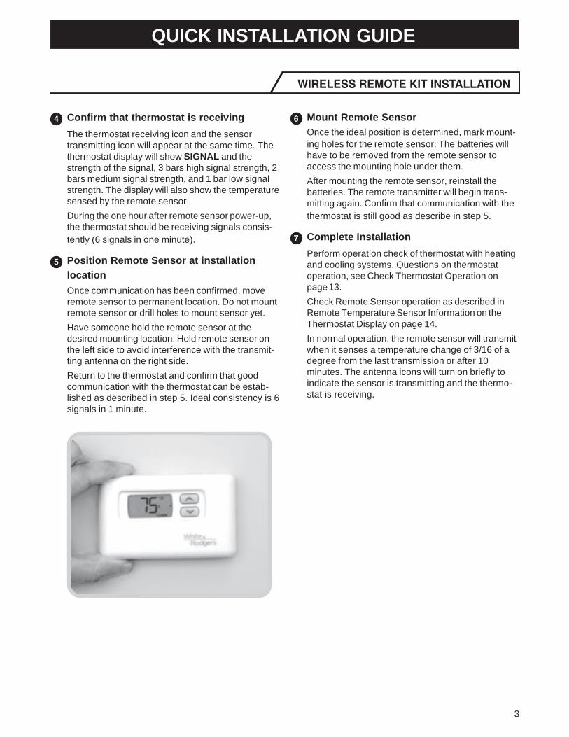
4 Confirm that thermostat is receiving
The thermostat receiving icon and the sensortransmitting icon will appear at the same time. Thethermostat display will show SIGNAL and thestrength of the signal, 3 bars high signal strength, 2bars medium signal strength, and 1 bar low signalstrength. The display will also show the temperaturesensed by the remote sensor.During the one hour after remote sensor power-up,the thermostat should be receiving signals consis-tently (6 signals in one minute).
5 Position Remote Sensor at installation
location
Once communication has been confirmed, moveremote sensor to permanent location. Do not mountremote sensor or drill holes to mount sensor yet.Have someone hold the remote sensor at thedesired mounting location. Hold remote sensor onthe left side to avoid interference with the transmit-ting antenna on the right side.Return to the thermostat and confirm that goodcommunication with the thermostat can be estab-lished as described in step 5. Ideal consistency is 6signals in 1 minute.
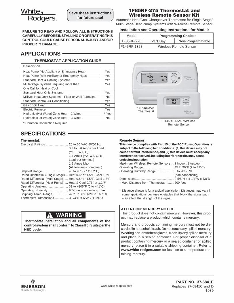
1F85RF-275 Thermostat andWireless Remote Sensor Kit
Automatic Heat/Cool Changeover Thermostat for Single Stage/Multi-Stage/Heat Pump Systems with Wireless Remote Sensor
Installation and Operating Instructions for Model:
Save these instructionsfor future use!
FAILURE TO READ AND FOLLOW ALL INSTRUCTIONSCAREFULLY BEFORE INSTALLING OR OPERATING THISCONTROL COULD CAUSE PERSONAL INJURY AND/ORPROPERTY DAMAGE.
APPLICATIONS
Description
Heat Pump (No Auxiliary or Emergency Heat) YesHeat Pump (with Auxiliary or Emergency Heat) YesStandard Heat & Cooling Systems YesMulti-Stage Systems requiring more than YesOne Call for Heat or CoolStandard Heat Only Systems YesMillivolt Heat Only Systems – Floor or Wall Furnaces NoStandard Central Air Conditioning YesGas or Oil Heat YesElectric Furnace YesHydronic (Hot Water) Zone Heat – 2 Wires * YesHydronic (Hot Water) Zone Heat – 3 Wires No
THERMOSTAT APPLICATION GUIDE
ATTENTION: MERCURY NOTICEThis product does not contain mercury. However, this prod-uct may replace a product which contains mercury.
Mercury and products containing mercury must not be dis-carded in household trash. Do not touch any spilled mercury.Wearing non-absorbent gloves, clean up any spilled mercuryand place in a sealed container. For proper disposal of aproduct containing mercury or a sealed container of spilledmercury, place it in a suitable shipping container. Refer towww.white-rodgers.com for location to send product con-taining mercury.
Model Programming Choices
1F85RF-270 5/1/1 Day Non-ProgrammableF145RF-1328 Wireless Remote Sensor
Thermostat:Electrical Ratings .......................... 20 to 30 VAC 50/60 Hz
0.2 to 0.6 Amps per Load(Y1, E/W1, G)1.5 Amps (Y2, W2, O, BLoad per terminal)1.5 Amps Max(All terminals combined)
Setpoint Range .............................. 45 to 90°F (7 to 32°C)Rated Differential (Single Stage) ... Heat 0.6° or 1.5°F, Cool 1.2°FRated Differential (Multi-Stage) ..... Heat 0.6° or 1.5°F, Cool 1.2°FRated Differential (Heat Pump) ..... Heat & Cool 0.75° or 1.2°FOperating Ambient ........................ 32 to +105°F (0 to +41°C)Operating Humidity ....................... 90% non-condensing max.Shipping Temp. Range .................. -4 to +150°F (-20 to +65°C)Thermostat Dimensions ............... 3-3/4"H x 6"W x 1-1/4"D
Remote Sensor:This device complies with Part 15 of the FCC Rules, Operation issubject to the following two conditions: (1) this device may notcause harmful interference, and (2) this device must accept anyinterference received, including interference that may causeundesired operation.Maximum Wireless Remote Sensors ....1 indoor, 1 outdoorOperating Range .................................... 45 to 90°F (7 to 32°C)Operating Humidity Range ..................... 0 to 90% RH
(non-condensing)Dimensions ............................................. 2-5/8"H x 4-1/4"W x 7/8"D* Max. Distance from Thermostat ..........200 feet
* Distance shown is for a typical application. Distances may vary insome applications because obstacles that block the signal pathmay affect the strength of the signal.
* Common Connection Required
1F85RF-270Thermostat
F145RF-1328 WirelessRemote Sensor
WARNING!Thermostat installation and all components of thecontrol system shall conform to Class II circuits per theNEC code.
www.white-rodgers.comPART NO. 37-6841E
Replaces 37-6841C and D1039
SPECIFICATIONS

5
Figure 1 – Thermostat base
Figure 2 – Back of thermostat base
RC/PSSwitch
Position DescriptionRC For Hardwire Applications. Requires Common Wire
from System Transformer to "C" Terminal on ThermostatPS For Power Stealing Applications. Use When Common
from the System Transformer is not Available forConnection to the "C" Terminal on the Thermostat
RC/PS Switch (Thermostat Power Option)
NOTE: If set to PS (Power Stealing), the thermostat "C" terminalmust not have a wire connected.
When the system is not providing enough power for thethermostat, the display will be bright when the system is notrunning and dim when the system is running. If the system isnot providing enough power, we recommend connecting a150 Ohm, 10 Watt resistor between terminals W and C of thefurnace or Y and C of the air conditioner, or both, to increasethe power provided.
ANTENNA
MOUNTING HOLE
MOUNTING HOLE
ELEC/GAS SWITCH
RC/PSSWITCH
MOUNTINGHOLE
MOUNTINGHOLE
ANTENNAWIRE
Figure 3 – Remote sensor base
REMOTECOMMUNICATIONRECEIVER
ANTENNAWIRE
Thermostat 24 VAC RequirementThe thermostat must have 24 VAC supplied for the receiverto operate. When the system wiring is connected, if a systemcommon wire is connected to terminal C, the system isproviding 24 VAC to the thermostat. The RC/PS switch (seeFig 1) must be in the RC position.
If the thermostat does not have a common wire connected toterminal C, the thermostat can use Power Stealing to get therequired 24 VAC. The RC/PS switch must be in the PSposition.
INSTALLATION
Do not remove battery tag to power the sensor with batteriesuntil instructed to do so. The thermostat requires 24 volt systempower to operate correctly. If the thermostat goes blank, systempower is not reliable and will be corrected in the System Powersection below.
1. Remove the packing material from the thermostat andsensor.
2. Pull the front cover of the thermostat straight off the base.Forcing or prying will cause damage to the control.
3. Using the thermostat base as a template, place on theselected wall locations and mark the location of allmounting holes (Figure 1), and the hole for the thermostatantenna wire illustrated in Figure 2.
4. Move base out of the way and drill the holes. If mountingholes drilled are too large and do not allow you to tightenbase snugly, use the plastic screw anchors (provided) forsecure mounting.
5. Make sure the remote communication receiver isplugged in properly to the thermostat and that theantenna wire is routed through the thermostat subbaseas shown in Figure 2.
6. Insert antenna wire into the wall and position base intomounting position.
7. Fasten base loosely to wall, using two mounting screws.Place a level against bottom of base (leveling is forappearance only and will not affect sensor operation)and then tighten screws.
8. In the thermostat location, push excess wire into wall andplug hole with a fire resistant material (such as fiberglassinsulation) to prevent drafts from affecting the thermostatoperation.
Mounting Thermostat and Sensor
CAUTION!To prevent electrical shock and/or equipment damage,disconnect electric power to system at main fuse orcircuit breaker box until power is required.
Before disconnecting wires from the old thermostat, markwires for terminal identification so the proper wiring connec-tions will be made to the new thermostat.
Remove Old Thermostat
Locate the thermostat/sensor about 5 ft. above floor level onan interior wall in an area that represents the average roomtemperature.
Do not mount directly on or near HVAC equipment or othersources of electrical noise.
Avoid locations close to windows or near adjoining outsidewalls, doors leading outside, areas close to air registers ortheir direct air flow or areas with poor circulation like alcoves.Avoid locating the sensor on a concrete wall, junction box ormetal plate. Make sure there are no electrical wires, metal,pipes or duct work in the part of the wall chosen for thesensor location.
For proper RF wireless communication, the antenna wireMUST be installed into the wall. If the antenna wire ishanging between the wall and the thermostat the RFcommunication may not be reliable
Antenna wire must be installed into the wall, it can not bebetween the thermostat and wall.
Thermostat and indoor sensor are not approved forinstallation in unconditioned space.
Guidelines for Thermostat/Sensor Locations

6
INSTALLATION9. Connect wires to thermostat terminals as required. Refer
to wiring diagrams Fig. 4 thru 7 for proper wiring.10.Apply system power and confirm that thermostat display
is on and SYSTEM mode is OFF. Press SYSTEM buttonto OFF if necessary.
11.Enter the configuration as described in ThermostatConfiguration Menu on page 10. Configure the thermo-stat for system operation. While in the configurationmenu, enable the indoor remote wireless sensor (item 4)by changing OFF to ON.
Confirming Communication of RemoteSensor to Thermostat
Before finding a good location to mount the remote sensor,confirm that the thermostat is receiving the remote sensorsignals consistently and at the best strength possible.
Reliable Communication: While the sensor is in the LearnMode, to be sure the thermostat and sensor have good commu-nication. The thermostat receiving icon and the sensor transmit-ting icon will appear and turn off at about the same time. Thethermostat will display SIGNAL and the strength of the signal.3 bars indicates a strong signal and the most desirable, 2 barsindicates a medium strength signal and 1 bar indicates a weaksignal which is acceptable if it can not be improved. Thethermostat display will also show the temperature sensed by theremote. The thermostat should receive 6 signals in 1 minute andthe signal strength should be 3 bars if possible.
1. Remove the battery tag from only the remote sensor. Thebattery tag must still be in the thermostat. The remote sensorwill begin transmitting a signal once every 10 seconds forone hour.
2. Place the remote sensor on the thermostat and check thatthe thermostat is receiving signals from the sensor. Confirmthat the sensor and thermostat have reliable communicationas described above in Reliable Communication.
3. Move the remote sensor to the room where it is to beinstalled. Do not mark a mounting location or drill holes yet.
4. Have someone hold the remote sensor at the locationselected for the remote sensor. Hold the remote sensor onthe left side to avoid interference with the transmittingantenna on the right side of the sensor.
6. Return to the sensor and confirm that reliable communica-tion with the sensor can be established again as describedin Reliable Communication. Have the sensor moved, ifnecessary to improve the signal strength if it is not a consis-tent signal with signal strength of 3 bars.
7. Once the ideal position for the sensor is determined, markmounting holes using the sensor base as a template (Figure3). The batteries will have to be removed to access amounting under them.
8. After the sensor is firmly attached to the wall and the batteriesare reinstalled, the remote sensor will begin transmittingagain for one hour. Return to the thermostat and once againconfirm that communication is still good as described inReliable Communication.
Battery LocationThe sensor requires 2 "AAA" alkaline batteries. Batteries areincluded at the factory with a battery tag to prevent powerdrainage. The battery tag must be removed to engage thebatteries. For best results, replace batteries once a year withnew premium brand alkaline batteries such as Duracell® orEnergizer®.
Electric/Gas Switch (Fan Option)The ELEC/GAS switch on the thermostat (Fig. 1) is factoryset to the ELEC position. In this position, the thermostat willpower the circulator fan on a call for heat. Electric heatsystems may require the switch to be in the ELEC position.
If your system does not require that the thermostat power thecirculator fan, this switch should be set to the GAS position.Typically, gas and oil heating systems do not require thethermostat to power the circulator fan during a call for heat. Ifyour heat is gas or oil, the switch should be set to the GASposition.
When the thermostat is configured for Heat Pump, thethermostat will always power the circulator fan on a call forheat in the HEAT mode. The ELEC/GAS switch must be setto match the type of Auxiliary heat your system uses forproper operation in the EMERgency mode.
Typical wiring diagrams are provided below for the following systems:Single Stage Heat/Cool systemsMulti-Stage Heat/Cool systems (No Heat Pump)Heat Pump system, one compressor or one speed compressor with Aux. HeatHeat Pump systems, two compressors or two speed compressor with Aux. Heat
Refer to the equipment manufacturers instructions for specific wiring information. After completing the connections configurethe thermostat in the Installer Configuration Menu to match your system type.
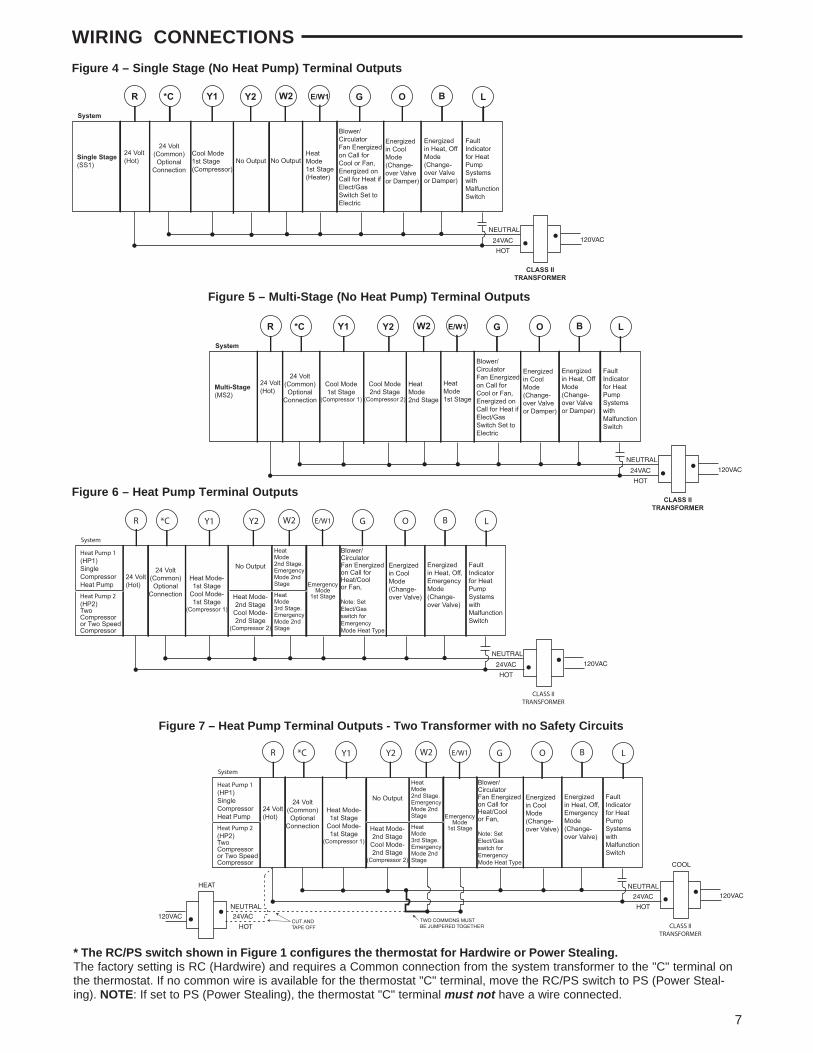
WIRING CONNECTIONS
7
Heat Pump 1(HP1)SingleCompressorHeat Pump
24 Volt(Hot)
Blower/CirculatorFan Energizedon Call forHeat/Coolor Fan,
Note: SetElect/Gasswitch forEmergencyMode Heat Type
24 Volt(Common)Optional
Connection
System
*C
CLASS IITRANSFORMER
HOT
24VAC
24VAC
COOL
HEAT NEUTRAL120VAC
FaultIndicatorfor HeatPumpSystemswithMalfunctionSwitch
LR E/W1Y2 G
EmergencyMode
1st Stage
Heat Mode-1st Stage
Cool Mode-1st Stage
(Compressor 1)
Y1 W2
Energizedin CoolMode(Change-over Valve)
O
Energized in Heat, Off,EmergencyMode(Change-over Valve)
B
Heat Mode-2nd Stage
Cool Mode-2nd Stage
(Compressor 2)
Heat Pump 2(HP2)TwoCompressoror Two SpeedCompressor
No Output
HeatMode2nd Stage.EmergencyMode 2nd Stage
HeatMode3rd Stage.EmergencyMode 2nd Stage
CUT AND TAPE OFF
TWO COMMONS MUSTBE JUMPERED TOGETHERHOT
NEUTRAL
120VAC
Multi-Stage(MS2)
24 Volt(Hot)
Blower/CirculatorFan Energizedon Call forCool or Fan,Energized onCall for Heat ifElect/GasSwitch Set toElectric
24 Volt(Common)Optional
Connection
System
*C
CLASS IITRANSFORMER
HOT
24VAC
NEUTRAL
120VAC
FaultIndicatorfor HeatPumpSystemswithMalfunctionSwitch
LR E/W1Y2 G
HeatMode1st Stage
Cool Mode1st Stage
(Compressor 1)
Y1
HeatMode2nd Stage
W2
Energizedin CoolMode(Change-over Valveor Damper)
O
Energized in Heat, OffMode(Change-over Valveor Damper)
B
Cool Mode2nd Stage
(Compressor 2)
Figure 5 – Multi-Stage (No Heat Pump) Terminal Outputs
Heat Pump 1(HP1)SingleCompressorHeat Pump
24 Volt(Hot)
Blower/CirculatorFan Energizedon Call forHeat/Coolor Fan,
Note: SetElect/Gasswitch forEmergencyMode Heat Type
24 Volt(Common)Optional
Connection
System
*C
CLASS IITRANSFORMER
HOT
24VAC
NEUTRAL
120VAC
FaultIndicatorfor HeatPumpSystemswithMalfunctionSwitch
LR E/W1Y2 G
EmergencyMode
1st Stage
Heat Mode-1st Stage
Cool Mode-1st Stage
(Compressor 1)
Y1 W2
Energizedin CoolMode(Change-over Valve)
O
Energized in Heat, Off,EmergencyMode(Change-over Valve)
B
Heat Mode-2nd Stage
Cool Mode-2nd Stage
(Compressor 2)
Heat Pump 2(HP2)TwoCompressoror Two SpeedCompressor
No Output
HeatMode2nd Stage.EmergencyMode 2nd Stage
HeatMode3rd Stage.EmergencyMode 2nd Stage
Figure 6 – Heat Pump Terminal Outputs
Figure 7 – Heat Pump Terminal Outputs - Two Transformer with no Safety Circuits
WIRING CONNECTIONS
* The RC/PS switch shown in Figure 1 configures the thermostat for Hardwire or Power Stealing.The factory setting is RC (Hardwire) and requires a Common connection from the system transformer to the "C" terminal onthe thermostat. If no common wire is available for the thermostat "C" terminal, move the RC/PS switch to PS (Power Steal-ing). NOTE: If set to PS (Power Stealing), the thermostat "C" terminal must not have a wire connected.
Single Stage(SS1)
24 Volt(Hot)
Blower/CirculatorFan Energizedon Call forCool or Fan,Energized onCall for Heat ifElect/GasSwitch Set toElectric
No Output
24 Volt(Common)Optional
Connection
System
*C
CLASS IITRANSFORMER
HOT
24VAC
NEUTRAL
120VAC
FaultIndicatorfor HeatPumpSystemswithMalfunctionSwitch
LR E/W1Y2 G
HeatMode1st Stage(Heater)
Cool Mode1st Stage(Compressor)
Y1
No Output
W2
Energizedin CoolMode(Change-over Valveor Damper)
O
Energized in Heat, OffMode(Change-over Valveor Damper)
B
Figure 4 – Single Stage (No Heat Pump) Terminal Outputs

8
THERMOSTAT/REMOTE SENSOR QUICK REFERENCE
Figure 8 – Thermostat display, buttons and switches
Before operating the thermostat, familiarize yourself with thedisplay and button functions. Both thermostat and remotesensor consist of two parts: the cover and the base. To removea cover, pull it straight out from the base. To replace a cover, lineit up with the base and press until the cover snaps into place onthe base.
The Thermostat Buttons and Switches and Display
1 Raises and lowers the temperature setting.
2 Light flashes every 20 seconds indicating acceptablesignal reception from indoor or outdoor remote sensor.
3 Buttons for setting time (Time), programming (Prgm),running program (Run) and bypassing program tohold a constant temperature (Hold).
4 SYSTEM button (COOL, AUTO, HEAT, OFF, EMERheat pump systems only).
5 FAN switch (ON, AUTO).
6 Displays the active temperature sensor (outside,remote, local) and its sensed temperature if more thanone sensor is enabled.
7 Displays ( ) when in keypad lockout mode.
8 Indicates day of the week.
9 Indicates the thermostat mode information:"HOLD" alternates with the system mode (see item 12)if the HOLD button is pressed to bypass the programand maintain a constant temperature.
10 Displays currently programmed set temperature (blankwhen SYSTEM is OFF).
11 Alternately displays the current time and the tempera-ture average of sensors (thermostat [local] and/orindoor remote) turned on.
12 "HEAT" is displayed when set to heating,"COOL" is displayed when set to cooling,"AUTO" is displayed when set for automatic change-over between heating and cooling.When "AUTO" is displayed, the currently active mode(Heat or Cool) will also display."EMER" is displayed flashing (heat pump systemsonly) when the thermostat is set to the EmergencyMode. Emergency is used to bypass the heat pumpand use only the back-up heating system."FLTR" is displayed as a reminder to change or cleanthe air filter after system has run for the programmedfilter time period.
13 Stage 1 & 2 indicator."STG 1" indicates when the first stage heat or cool isenergized. "STG + 2" indicates when the second stageheat or cool is energized. "+2" blinking indicatesAuxiliary Heat stages are energized on Heat PumpSystems.
2
45
14 Displays "LR" when the limited range feature isactivated. Limited range limits the temperature thethermostat can be set to.
15 Indicates the system is sending a fault signal to thethermostat "L" terminal. This does not indicate a faultin the thermostat.
16 Antenna will display for a few seconds when the remoteor outdoor transmitted signal is received.
17 Indicates the current signal strength level of the remotetemperature system. Signal strength level is low (onebar on), medium (two bars on) or high (three bars on).The remote will operate with 1 bar showing.
8
6
9
12
7
10
1311
14 15
17
16

9
1
2
THERMOSTAT/SENSOR QUICK REFERENCEThe Sensor Buttons and Display
1 Raises the Comfort adjust graph setting.
2 Lowers the Comfort adjust graph setting.
3 Sensed temperature from –40 to 140°F with °F and °Cindicator
4 Channel identification A B C O indicator
5 9 bar comfort adjust graph with H (hotter) and C (cooler)
6 Transmission occurrence indicator
7 Keypad lockout indicator
8 Calibrate temperature offset indicator
9 Learn mode activated indicator
10 Low battery indicator
11 Temperature offset used when hold time is active
12 Displays PWR and on to indicate normal operationwith display turned OFF
Figure 9 – Remote Sensor display and buttons
ABCO LOCK
LEARNBATT PWR HLD
H
CALIB
C
o
11 9
6
8
7
10
5
4
12
3
5
5
A
o6
4
3
5
Normal Operation
Configuration Items

10
Press Displayed Press or Step Button(s) (Factory Default) to select Comments
1 System MS2 SS1, HP2, HP1 Selects Single stage, Multi-stage, or Heat Pump(Single stage or 2-stage) system configuration
2 System LER (OFF) LER (ON) Selects learn mode OFF or ON
3 System OUTSIDE (OFF) OUTSIDE (ON) Selects OUTSIDE sensor OFF or ON
4 System REMOTE (ON) REMOTE (OFF) Selects REMOTE (indoor) sensor OFF or ON
5 System LOCAL (ON) LOCAL (OFF) Selects LOCAL sensor ON or OFF
6 System CH (0) 1 to 9 Select Receiver frequency offset
7 System PRG 4 PRG 0, PRG 2 Selects Programmable Periods
8 System EMR (ON) EMR (OFF) Selects Energy Management Recovery OFF or ON
9 System CR HEAT COOL (FA) SL Selects Fast or Slow cycle selection
10 System CL (OFF) CL (ON) Selects Compressor Lockout CL OFF or ON
11 System CdL (ON) CdL (OFF) Selects Backlight Display ON or OFF
12 System FA HEAT COOL (ON) FA HEAT COOL (OFF) Selects Fast Second Stage ON or OFF
13 System 0 FLTR 0–1950 (increments of 50) Selects filter replacement run time.0 =Disabled
14 System 0 F 4 LO to 4 HI Selects Temperature Display Adjustment 4 LO 4 HI(Room Temperature)
15 System 4:00 HOLD 0:00 to 8:00 Selects Temporary Program Override Time(Increments of 15 minutes) 0:00 =Disabled
16 System F C For C selectionSelects temperature display as F° or C°
17 System LR HEAT (90) LR 62 to LR 89 Selects Limited HEAT range
18 System LR COOL (45) LR 46 to LR 82 Selects Limited COOL range
19 System CA (OFF) CA (ON) Selects Comfort Alert Lock
20 System OFF LOCK ON LOCK Selects Button pad Lockout
21 0 00 LOCK 001 to 999 Selects Buttonpad lockout combination numberPress System to set code
Run Returns to the OFF mode
The configuration menu allows you to set certain thermostatoperating characteristics to your system or personal require-ments.
Set SYSTEM button to OFF, then simultaneously press and to enter configuration menu. The display will
show the first item in the configuration menu.
The configuration menu table summarizes the configurationoptions. An explanation of each option follows.
Press SYSTEM to change to the next menu item. To exit themenu and return to the program operation, press RUN. If nokeys are pressed within fifteen minutes, the thermostat willrevert to normal operation.
1) Single Stage, Multi-stage or Heat Pump ConfigurationThis menu item requires you configure the thermostat tomatch your system. Choose your system option from thetable below:
System Type Select Option
Single Stage Heat/Cool systems SS1Multi-Stage Heat/Cool systems (No Heat Pump) MS2Heat Pump system, 1 compressor or 1 speed compressor HP1Heat Pump systems, 2 compressors or 2 speed compressor HP2
The thermostat is factory defaulted to MS2. To select adifferent option, press the or key to scroll throughthe choices.
THERMOSTAT CONFIGURATION MENU
2) Select Learn Mode On or Off – Selecting LER Onenables the learn mode of the thermostat receiver. Yourthermostat is configured at the factory to recognize theremote sensor shipped with it. The Learn Mode Optionis used only when required as described in Learn ModeOption.
3) Selects OUTSIDE sensor OFF or ON – SelectingOUTSIDE ON enables the thermostat to read a wirelessoutdoor temperature sensor that has been configuredfor Sensor O in the Learn Mode. This allows the thermo-stat to display the outdoor temperature reading.
4) Selects REMOTE sensor OFF or ON – SelectingREMOTE ON allows the thermostat to sense an indoorremote sensor that has been set-up the Learn mode.The maximum number of Indoor Remote Sensors is 1configured to sensor A, B or C.
5) Selects LOCAL sensor ON or OFF – Appears ifRemote is set to ON. Selecting LOCAL ON allows thethermostat to use the onboard temperature sensorexclusively or for averaging with the remote sensorreadings. To control temperature using only the indoorremote sensor temperature(s), use the or buttonsto select LOCAL OFF.
6) Select Receiver frequency offset – Appears if Remote isset to ON. This option allows you to select a differentchannel than the factory default for communicationbetween the thermostat and remote sensor. Note: If a
INSTALLER/CONFIGURATION MENUPress the System button until OFF is displayed, then press the and simultaneously

11
14) Select Temperature Display Adjustment 4 LO to 4 HI –Allows you to adjust the room temperature display up to4° higher or lower. Your thermostat was accuratelycalibrated at the factory but you have the option tochange the display temperature to match your previousthermostat. The current or adjusted room temperature willbe displayed on the left side of the display.
15)Select Temporary Program Override Time – The thermo-stat can hold any temperature you set it to for the amountof time you select on this option. Your choices are 0:00 to8:00 hours in 15 minute increments. 0:00 means disable.Example:1. You have selected 3:00 hours for the Temporary Pro-
gram Override time period.2. With the thermostat set to Heat or Cool, press HOLD
for approximately 5 seconds until "HOLD time 3:00"(indicating 3 hours) appears as a setting reminder.
3. After releasing the button, "HOLD" on the display willblink.
4. Use or to set the temperature to your preference. The thermostat will maintain this temperaturesetting for 3 hours with "HOLD" blinking to remind youit is in Temporary Hold. After 3 hours, the thermostatwill go back to the program temperature and "HOLD"will no longer blink or display.
16)Select F° or C° Readout – Changes the display readoutto Celsius or Fahrenheit as required.
17)Limited Heat Range – This feature provides a maximumsetpoint temperature for heat. The default setting is 90°F. Itcan be changed between 62°F and 89°F by pressing the
or key.18)Limited Cool Range – This feature provides a minimum
setpoint temperature for cool. The default setting is 45°F. Itcan be changed between 46°F and 82°F by pressing the
or key.19)Comfort Alert – This feature is available in Passive
mode on this thermostat. If a Comfort Alert module isconnected, the thermostat will receive and flash the faultcodes from the Comfort Alert module.
20 & 21) Keypad Lockout – This menu selection willdisplay lock ( ) icon. The and are used to togglethe function and display the lock icon and OFF (keypadnot locked out, default) indicating in the time digits to thelock icon and ON (keypad locked out). When the keypadlockout function is enabled (ON), and the SYSTEM buttonis pressed again, the display will indicate the number 000(default, still disabled) in the time digits. The and are used to set the combination number from 0 to 999. Ifa combination of 000 is selected and the SYSTEM buttonis pressed, the menu will be exited and keypad will not belocked. If 1 to 999 is selected and the SYSTEM button ispressed again, the combination is locked into non-volatilememory and the menu is exited. The lock icon (todesignate keypad locked with a valid combination) willdisplay when the menu is exited. The SYSTEM buttonwill operate for 10 seconds after the menu mode is exitedto allow the user to change the mode from OFF to thedesired system mode.While the keypad is locked out, a simultaneous press of and will enter the menu item from any mode instead ofonly OFF mode. When the menu is entered with thekeypad lockout feature enabled, the first menu itemdisplayed is the combination code 0. The or keysare used to set the combination unlock number from 0 to999. If the unlock number matches exactly with thecombination lock number stored in memory when theSYSTEM button is pressed, the keypad is unlocked andthe lock icon is removed. If the unlock number does notmatch when the SYSTEM button is pressed, menu isexited and the keypad remains disabled.To reset the combination code and unlock the keypad if thecode is forgotten, see troubleshooting section, page 20.
different channel is selected on the thermostat it must alsobe changed to the same setting on the remote. This isonly used in areas where there are other wirelessdevices or electronic equipment that interfere with thedefault frequency of the thermostat/remote sensorcommunication.
7) Programmable Periods – This control can be config-ured for 4, 2 or 0 programmable periods. The displayindicates "PRG 4" in the display as default. The program-mable periods can be changed to 2 or 0 by pressing the
or keys. With "PRG 0" selected for non-program-mable, SYSTEM key selection will skip EMR (item 8) andtemporary program override (item 15).
8) Select Energy Management Recovery OFF or ON –Energy Management Recovery (EMR) causes thethermostat to start heating or cooling early to make thebuilding temperature reach the program setpoint at thetime you specify. Heating will start 5 minutes early forevery 1° of temperature required to reach setpoint.Example: You select EMR and have your heatingprogrammed to 65° at night and 70° at 7 AM. If thebuilding temperature is 65° the difference between 65°and 70° is 5°. Allowing 5 minutes per degree the thermo-stat setpoint will change to 70° at 6:35 AM. Cooling allowsmore time per degree because it takes longer to reachtemperature.
9) Fast or Slow Cycle Selection – The factory defaultsetting is fast cycle, which cycles 1st stage at approxi-mately 1.2°F and 2nd stage 0.75°F. If you prefer slowcycle, press the temperature key to change to SL. The 1ststage and 2nd stage would be 1.5°F and 1.2°F respec-tively.
10)Select Compressor Lockout CL OFF or ON – SelectingCL ON will cause the thermostat to wait 5 minutes beforeturning on the compressor if the heating and coolingsystem loses power. It will also wait 5 minutes minimumbetween cooling and heating cycles. This is intended tohelp protect the compressor from short cycling. Somenewer compressors already have a time delay built in anddo not require this feature. Your compressor manufac-turer can tell you if the lockout feature is already presentin their system. When the thermostat compressor timedelay occurs it will flash the setpoint for about fiveminutes.
11)Select Backlight Display – The display backlight improvesdisplay contrast in low lighting conditions. When the "C"terminal is powered, selecting backlight CdL ON will keepthe light on continuously. Select backlight OFF will keepthe light on momentarily after any key is pressed. When the"C" terminal is not powered, the light will be on momen-tarily after any key is pressed no matter the backlight isselected ON or OFF.
12)Select Fast Second Stage On or OFF – For Heat:During normal operation if the setpoint temperature ismanually raised by 3°F or more above the actualtemperature with the button, and the fast secondstage feature is enabled, FA ON, the second stage willenergize immediately.For Cool: During normal operation if the setpoint tem-perature is manually lowered by 3°F or more below theactual temperature with the button, and the fastsecond stage feature is enabled, FA ON, the secondstage will energize immediately.
13)Select filter replacement run time – The thermostat willdisplay "FLTR" after a set time of operation. This is areminder to change or clean your air filter. This time can beset from 0 to 1950 hours in 50 hour increments. A selec-tion of 0 will cancel this feature. When "FLTR" isdisplayed, you can clear it by pressing HOLD and RUN atthe same time. This resets the timer and starts counting thehours until the next filter change. Contact your systemmanufacturer for a specific replacement/maintenanceinterval.
THERMOSTAT CONFIGURATION MENU
12
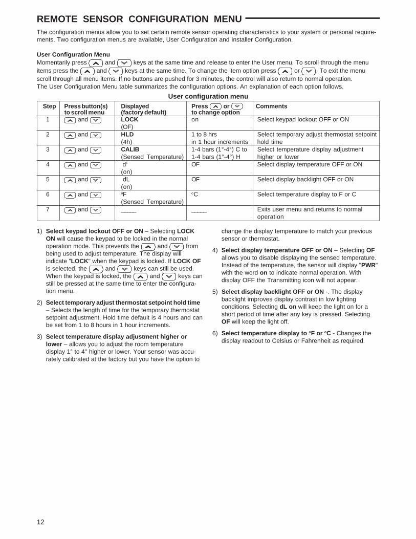
REMOTE SENSOR CONFIGURATION MENUThe configuration menus allow you to set certain remote sensor operating characteristics to your system or personal require-ments. Two configuration menus are available, User Configuration and Installer Configuration.
User Configuration MenuMomentarily press and keys at the same time and release to enter the User menu. To scroll through the menuitems press the and keys at the same time. To change the item option press or . To exit the menuscroll through all menu items. If no buttons are pushed for 3 minutes, the control will also return to normal operation.The User Configuration Menu table summarizes the configuration options. An explanation of each option follows.
Step Press button(s) Displayed Press or Commentsto scroll menu (factory default) to change option
1 and LOCK on Select keypad lockout OFF or ON(OF)
2 and HLD 1 to 8 hrs Select temporary adjust thermostat setpoint(4h) in 1 hour increments hold time
3 and CALIB 1-4 bars (1°-4°) C to Select temperature display adjustment(Sensed Temperature) 1-4 bars (1°-4°) H higher or lower
4 and dF OF Select display temperature OFF or ON(on)
5 and dL OF Select display backlight OFF or ON(on)
6 and oF oC Select temperature display to F or C(Sensed Temperature)
7 and _____ _____ Exits user menu and returns to normaloperation
User configuration menu
1) Select keypad lockout OFF or ON – Selecting LOCKON will cause the keypad to be locked in the normaloperation mode. This prevents the and frombeing used to adjust temperature. The display willindicate "LOCK" when the keypad is locked. If LOCK OFis selected, the and keys can still be used.When the keypad is locked, the and keys canstill be pressed at the same time to enter the configura-tion menu.
2) Select temporary adjust thermostat setpoint hold time– Selects the length of time for the temporary thermostatsetpoint adjustment. Hold time default is 4 hours and canbe set from 1 to 8 hours in 1 hour increments.
3) Select temperature display adjustment higher orlower – allows you to adjust the room temperaturedisplay 1° to 4° higher or lower. Your sensor was accu-rately calibrated at the factory but you have the option to
change the display temperature to match your previoussensor or thermostat.
4) Select display temperature OFF or ON – Selecting OFallows you to disable displaying the sensed temperature.Instead of the temperature, the sensor will display "PWR"with the word on to indicate normal operation. Withdisplay OFF the Transmitting icon will not appear.
5) Select display backlight OFF or ON -. The displaybacklight improves display contrast in low lightingconditions. Selecting dL on will keep the light on for ashort period of time after any key is pressed. SelectingOF will keep the light off.
6) Select temperature display to oF or oC - Changes thedisplay readout to Celsius or Fahrenheit as required.

13
REMOTE SENSOR CONFIGURATION MENUInstaller Configuration MenuYour thermostat is configured at the factory to recognize the remote sensor it is shipped with as indoor sensor A. The InstallerConfiguration Menu is used only when adding or replacing a remote sensor or selecting a frequency offset.Press and buttons at the same time for a minimum of five seconds then release to enter the Installer menu. Toscroll through the menu items, momentarily press the and buttons at the same time. To change the item option,press or . To exit the menu scroll through all menu items. If no buttons are pushed for 3 minutes, the control willreturn to normal operation. The Installer Configuration Menu table summarizes the configuration options. An explanation ofeach option follows.
Step Press button(s) Displayed Press or Commentsto scroll menu (factory default) to change options
1 and LEARN on Select learn mode OFF or ON(OF) (will be ON for one hour after sensor
power-up) 2 and CH B, C, O Select sensor identification as A, B, C or O
(A) 3 and C 1 through 9 Select transmitter frequency offset
(0) 4 and _____ _____ Exit installer menu and return to normal
operation
Installer Configuration Menu
1) Select learn mode OFF or ON – Selecting LEARN onenables the sensors learning mode. In the learning modethe sensor will transmit identification information onceevery 10 seconds for a period of 10 minutes. The LEARNicon will be displayed during the learning mode. TheTransmitting icon will be displayed for a short period oftime with each transmission. See Learn Mode Option.If the display is selected OFF, the Transmit icon andLearn icon will not appear. Learn mode is ON at power-up for one hour.
2) Select sensor identification from A to O – For multiplesensors systems, each sensor must have a designatedidentification. The thermostat can operate with one indoorsensor and one outdoor sensor. For indoor sensors youmay select A, B or C. For outdoor sensor you must selectO.
3) Select transmitter frequency offset – The sensor’stransmitter operates on 418MHz radio frequency bydefault. Interference may occur if another device orequipment operates on the same frequency. The interfer-ence may degrade the communications between thesensor and the thermostat. To avoid interference, youmay select a different radio frequency for your sensor.This menu item allows you to select a radio frequencyoffset from 1 to 9MHz from the base frequency. Forexample; if you selected an offset of 4, the transmitterradio frequency will be 418MHz + 4MHz = 422MHz. Notethat the sensor’s transmitter and the thermostat’s receivermust operate on the same frequency to communicate. Tochange thermostat’s receiver frequency please refer toThermostat Configuration Menu (Item 6).
OPERATING YOUR THERMOSTAT AND REMOTE SENSOR
NOTECheck Thermostat Operation
To prevent static discharge problems, touch side ofthermostat to release static build-up before touchingany keys.
Do not allow the compressor to run unless the compres-sor oil heaters have been operational for 6 hours andthe system has not been operational for at least 5minutes.
CAUTION!
If at any time during testing your system does not operateproperly, contact a qualified service person.
Fan OperationIf your system does not have a G terminal connection, skip toHeating System.
1. Turn on power to system.2. Move FAN switch to ON position. The blower should
begin to operate.3. Move FAN switch to AUTO position. The blower should
stop immediately.
Heating System1. Press SYSTEM button to select HEAT. If the auxiliary
heating system has a standing pilot, be sure to light it.2. Press to adjust thermostat setting to 1° above room
temperature. The heat pump system should begin tooperate. The display should show "STG1". However, if thesystem configuration is set to HP1 or HP2 and setpointtemperature display is flashing, the 5 minute compressorlockout feature is operating (see Configuration menu,item 10).
3. Adjust temperature setting to 3° above room temperature.If your system configuration is set at MS2, HP2 or HP1,the auxiliary heat system should begin to operate andthe display will show "STG 1+2".
4. Press to adjust the thermostat below room tempera-ture. The heating system should stop operating.

14
CAUTION!
Emergency SystemEMER bypasses the Heat Pump to use the heat source wiredto terminal E/W1 on the thermostat. EMER is typically usedwhen compressor operation is not desired, or you preferback-up heat only.1. Press SYSTEM button to select EMER. "EMER" will flash
on the display.2. Press to adjust thermostat setting above room
temperature. The Emergency heating system will begin tooperate. The display will show "STG1" flashing "EMER"and "HEAT" to indicate that the Emergency system isoperating.
3. Press to adjust the thermostat below room tempera-ture. The Emergency heating system should stop operat-ing.
To prevent compressor and/or property damage, if theoutdoor temperature is below 50°F, DO NOT operatethe cooling system.
Cooling System1. Press SYSTEM button to select COOL.2. Press to adjust thermostat setting below room
temperature. The blower should come on immediately onhigh speed, followed by cold air circulation. The displayshould show "STG1". If the setpoint temperature displayis flashing, the compressor lockout feature is operating(see Configuration menu, item 5).
3. Adjust temperature setting to 3° below room temperature.The second stage cooling should begin to operate andthe display should show "STG 1+2".
4. Press to adjust the temperature setting above roomtemperature. The cooling system should stop operating.
Remote Temperature Sensor Informationon the Thermostat Display
During normal operation, the upper left of the thermostatdisplay changes every 6 seconds to show the temperaturesat the sensors that are turned on in the configuration menu.The sensors are the thermostat (LOCAL), the outdoorremote sensor (OUTDOOR) and the indoor remote sensor(REMOTE). Below that, the display alternately shows thetime and temperature average of the sensors that are turnedon.
The word "SIGNAL" is shown along with number of bars (1-3) indicating the relative signal strength. More bars meanbetter reception. The antenna icon also displays for fewseconds when information from the remote sensor isreceived.
If the thermostat does not receive an update signal from anenabled remote sensor (REMOTE or OUTDOOR) for 30minutes or more, the thermostat will display FAULT andANTENNA icons continuously. The REMOTE or OUTDOORsensor that has communication with the thermostat inter-rupted will display a temperature of --. If the active sensor isthe REMOTE, the thermostat will revert back to LOCALsense only mode.
OPERATING YOUR THERMOSTAT AND REMOTE SENSOR
Automatic System ChangeoverWhen the thermostat is in the AUTO mode, the thermostatwill call for heat or cool depending on the room temperature.The setpoint temperature displayed will be the last modecalled. If the last system cycle was heat, the HEAT setpointwill be displayed. If the room temperature raises above theHEAT setpoint and the COOL setpoint and a call for cool isrequired, the temperature displayed will change to be theCOOL setpoint.
If you manually override the temperature in AUTO and itdoes not switch to the mode (HEAT or COOL) that you want,press the and keys once, at the same time to switchmodes. At the end of your override time it will revert back toAUTO.
Second Stage Time DelayYour thermostat is designed to determine the optimum timeto activate the second stage. Simply raising the temperaturein heating or lowering it in cooling will not always force thethermostat to bring the second stage on quickly. If the fastsecond stage option in the configuration menu (step 12) isset to "OFF", there is a delay from 0-30 minutes dependingon the performance of the first stage of the system.
EXAMPLE: For the last 2 hours the thermostat is set on 70°and the room temperature is 70° with the equipment usingonly the first stage of heat. Since the equipment is keepingthe temperature within 1 degree of setpoint, the thermostatwill delay second stage for a longer time if you manuallyraise the temperature or if the room temperature quicklychanges. Once the second stage comes on, it will come onsooner the next time there is a difference between thesetpoint and the room temperature. The net effect of thestaging program is that when the first stage is capable ofholding temperature, the second stage will delay longer.
When the thermostat calculates that first stage cannot maketemperature in a reasonable time, the second stage willcome on sooner. This built in function automatically opti-mizes the use of additional stages of heat or cool.
Learn Mode OptionYour thermostat is configured at the factory to recognize thewireless remote sensor shipped with it. This sensor is storedas Sensor A. The Learn Mode Option must be performed onthe thermostat and wireless remote sensor if:
• A wireless remote sensor is added to another channel.• The wireless remote sensor is replaced.• The thermostat is replaced.• The thermostat has been reset using , , and SYSTEM keys.
During the Learn Mode, the wireless remote sensor willtransmit identification information every ten seconds for tenminutes. In this ten-minute period, the display will show“LEARN” and the antenna icon will show for a short time witheach transmission. The thermostat will be receiving thetransmitted identification information.
To perform the Learn Mode on the thermostat and sensor:Remove the batteries from all wireless remote sensors inthe same building except the sensor you are going to putinto the Learn Mode. This will prevent interference fromthe other sensors.

15
OPERATING YOUR THERMOSTAT AND REMOTE SENSOR
Be sure that the remote sensor is set for the properidentification (A, B or C for indoor or O for outdoor) andthe thermostat and remote sensor are set to the samefrequency.On the thermostat, enter the thermostat ConfigurationMenu by pressing the SYSTEM button to OFF and thenmomentarily pressing and at the same time.Momentarily press SYSTEM button to advance to step 2of the Configuration Menu. The display will show “LER”and “OFF”.Momentarily press or to select “LER” and “On”.The display will flash “LER” with “On” displayed con-stantly.On the wireless remote sensor, enter the InstallerConfiguration Menu by pressing and for fiveseconds. The remote sensor display will change to“LEARN OFF”.Momentarily press or to select “LEARN On”.Exit the menu. The sensor will begin the Learn mode.After the thermostat has successfully identified theremote sensor in approximately one minute, the sensorinformation will be stored and the thermostat display willchange to “LER” and “OK”.
If the identification sequence is not successful after tenminutes, the thermostat display will show “LER”, “Fault” andthe antenna icon. If the Learn Mode is unsuccessful, refer toTroubleshooting section, Antenna + Fault.
If you are replacing a thermostat that has more than onewireless remote sensor, the Learn Mode must be performedfor each sensor. Once a sensor has been identified, it willremain in the thermostat memory until the Learn Mode isperformed again and a different sensor for the storedchannel is identified.
Wireless Remote IndoorTemperature Averaging
Your thermostat is designed to sense the temperature ofthe indoor remote sensor and average or weight it with thelocal sensor in the thermostat for each program period. Theaveraging will only be active when both the local and theindoor remote sensors are functional and turned on in theconfiguration menu. When the thermostat is placed in viewschedule mode (press PRGM once), the weight of theindoor remote sensor will be shown on the left side of thedisplay when HOLD button is pressed. The weightingclasses of the indoor remote sensor are designated as A(default for average weight), HI (high weight), or LO (lowweight). The HI weight is two times the weight of A (aver-age). The A weight is two times the weight of LO. The weightof the local sensor is fixed to A (average weight).The actual temperature displayed, in the clock digits, in thenormal operation mode is the mathematical weighted sumof the enabled functioning sensors. For example, if the localsensed temperature is 80°F and the remote sensedtemperature is 70°F then:
If weight selected is HI , then the averaged temperature is(2 x (80°F) + 4 x (70°F))/ 6 = 73.3°F.If weight selected is A , then the averaged temperatureis (2 x (80°F) + 2 x (70°F))/ 4 = 75°F.If weight selected is LO , then the averaged temperatureis (2 x (80°F) + 1 x (70°F))/ 3 = 76.6°F.
The example above shows that the weight selected would
prioritize the overall averaged temperature between the twosensors. The high weight selection caused the remotesensor to carry more weight in the calculated temperatureaverage than the local sensor. The low weight selectioncaused the remote sensor to carry less weight in thecalculated temperature average than the local sensor.
Choose the Fan Setting (Auto or On)Set the FAN Switch to Auto or On.Fan Auto is the most commonly selected setting and runsthe fan only when the heating or cooling system is on.Fan On runs the fan continuously for increased air circula-tion or to allow additional air cleaning.
Choose the System Setting(Heat, Off, Cool, Auto, Emer)
Press the SYSTEM button to select:Heat: Thermostat controls only the heating system.Off: Heating and Cooling systems are off.Cool: Thermostat controls only the cooling system.Auto: Auto Changeover is used in areas where both heatingand cooling may be required on the same day. AUTO allowsthe thermostat to automatically select heating or coolingdepending on the indoor temperature and the selected heatand cool temperatures. When using AUTO, be sure to set theCooling temperatures more than 1° Fahrenheit higher thanthe heating temperature.Emer: Setting is available only when the thermostat isconfigured in HP1 or HP2 mode.
Manual Operation forNon-Programmable Thermostats
Press the SYSTEM button to select Heat or Cool and usethe or buttons to adjust the temperature to yourdesired setting. After selecting your desired settings you canalso press the SYSTEM button to select AUTO to allowthe thermostat to automatically change between Heat andCool.
Manual Operation (Bypassing the Program)Programmable Thermostats
Press or and adjust the temperature wherever youlike. Then press HOLD. This will override the program. TheHOLD feature bypasses the program and allows you toadjust the temperature manually, as needed. Whatevertemperature you set in HOLD will be maintained 24 hours aday, until you manually change the temperature or pressRUN to cancel HOLD and resume the programmed sched-ule.
Program Override (Temporary Override)Press or buttons to adjust the temperature. This willoverride the temperature setting for a (default) four houroverride period. The override period can be shortened orlengthened by adjusting the temporary hold time in theconfiguration menu.Example: If you turn up the heat during the morning pro-gram, it will be automatically lowered later, when thetemporary hold period ends. To cancel the temporary settingat any time and return to the program, press RUN.If the SYSTEM button is pressed to select AUTO thethermostat will change to Heat or Cool, whichever ran last. Ifit switches to heat but you want cool, or it changes to coolbut you want heat, press both and buttons simulta-neously to change to the other mode.

16
PERIOD WEEKDAYS (5 DAYS) SATURDAY (1 DAY) SUNDAY (1 DAY)START REMOTE START REMOTE START REMOTETIME TEMP WEIGHT TIME TEMP WEIGHT TIME TEMP WEIGHT
MORNDAYEVENITEMORNDAYEVENITE
PROGRAMMING YOUR THERMOSTATThis section will help you plan your thermostat's program tomeet your needs. For maximum comfort and efficiency, keepthe following guidelines in mind when planning your program.
• When heating (cooling) your building, program the temper-atures to be cooler (warmer) when the building is vacant orduring periods of low activity.
• During early morning hours, the need for cooling is usuallyminimal.
Planning Your ProgramLook at the factory preprogrammed times and temperaturesshown in the sample schedule. If this program will suit yourneeds, simply set the time and day and press the RUNbutton to begin running the factory preset program.
If you want to change the preprogrammed times and tem-peratures, follow these steps.
Determine the time periods and temperatures for yourprogram. You must program four periods for each day.However, you may use the same heating and coolingtemperatures for consecutive time periods. You can choosestart times, heating temperatures, and cooling temperaturesindependently (for example, you may select 5:00 AM and 70°as the weekday 1st period heating start time and tempera-ture and also choose 7:00 AM and 76° as the weekday 1stperiod cooling start time and temperature).
Use the table to plan your program time periods and thetemperatures you want during each period. Fill in thecomplete table to have a record of your programs.
OPERATING YOUR THERMOSTAT AND REMOTE SENSOR
PERSONAL PROGRAM
Remote Sensor OperationThe sensor monitors the temperature and sends informationto the thermostat. Updated information is sent to the thermo-stat when the temperature changes 3/16 degree or morefrom the last update. If the temperature does not change for10 minutes, the sensor will transmit to assure communica-tion.
Low Battery power: The sensor will display the word LOalong with BATT icon to indicate a low battery powercondition. The 2 "AAA" batteries must be replaced to ensurea proper sensor performance. For optimum performance,replace batteries once a year with new premium brandalkaline batteries such as Duracell® or Energizer®.
Thermostat Setpoint Offset: The thermostat displayedsetpoint can be offset using the remote sensor and buttons. The remote setpoint offset is defaulted to 0 (zero).Press to increase the setpoint up to 4o (four bars C) orpress to decrease the setpoint up to 4o (four bars H). Afterthe last button press, the remote sensor will delay for tenseconds and then transmit the setpoint offset information.When the thermostat receives the offset information, it willstart a remote sensor temporary hold for the length of timeset in the Remote Sensor Configuration Menu, item 2. Thesetpoint temperature will be changed by the amount of offsettransmitted. HOLD on the thermostat will flash and HLD onthe sensor will display for the period of the hold. The remotesensor Thermostat Setpoint offset can be cancelled at anytime by pressing the thermostat RUN button.
PERIOD WEEKDAYS (5 DAYS) SATURDAY (1 DAY) SUNDAY (1 DAY)START REMOTE START REMOTE START REMOTETIME TEMP WEIGHT TIME TEMP WEIGHT TIME TEMP WEIGHT
MORN 6:00 AM 70 F A 6:00 AM 70 F A 6:00 AM 70 F ADAY 8:00 AM 62 F A 8:00 AM 62 F A 8:00 AM 62 F AEVE 5:00 PM 70 F A 5:00 PM 70 F A 5:00 PM 70 F ANITE 10:00 PM 62 F A 10:00 PM 62 F A 10:00 PM 62 F AMORN 6:00 AM 78 F A 6:00 AM 78 F A 6:00 AM 78 F ADAY 8:00 AM 85 F A 8:00 AM 85 F A 8:00 AM 85 F AEVE 5:00 PM 78 F A 5:00 PM 78 F A 5:00 PM 78 F ANITE 10:00 PM 82 F A 10:00 PM 82 F A 10:00 PM 82 F A
FACTORY PROGRAM
CO
OL
HE
AT
CO
OL
HE
AT

PROGRAMMING
Enter Heating Program1. Press the SYSTEM button to HEAT.2. Press PRGM once. "MO TU WE TH FR" (indicating
weekday program) will appear in the display. Also dis-played are the currently programmed start time for the1st heating period and the currently programmed temp-erature (flashing).
EXAMPLE:
This display window shows that for the 1st weekdayperiod, the start time is 6:00 AM and 70° is the program-med temperature (this example reflects factory prepro-gramming.
3. Press or to change the displayed temperatureto your selected temperature for the 1st heating programperiod.
4. Press TIME once (the programmed time will flash). Press or until your selected time appears. The time
will change in 15 minute increments. When your selectedtime is displayed, press TIME again to return to thechange temperature mode.
5. If both the local and the remote sensors are enabled, thenyou may press HOLD button to change the remote sensor
Setting the Clock and DaySet Current Time and Day
1. Press TIME button once. The display will show the houronly.
EXAMPLE:
2. Press and hold either or until you reach thecorrect hour and AM/PM designation (AM begins at mid-night; PM begins at noon). A will indicate for AM. P willindicate for PM in the minutes digits.
3. Press TIME once again. The display window will showthe minutes only.
EXAMPLE:
4. Press and hold either or until you reach thecorrect minutes.
5. Press TIME once again. The display will show the day ofthe week.
6. Press or until you reach the current day of theweek.
7. Press RUN once. The display will show the correct timeand room temperature alternately.
This thermostat starts the programmed temperature earlierthan the time selected in your program. This allows thesystem to reach your setting by the time you specify in yourprogram. This feature is called EMR (Energy ManagementRecovery). If you do not want the thermostat to start early,you may cancel the EMR feature in the Configuration Menu.
17
weighting setting. Remote icon will display. The pro-grammed weight (A, HI or LO) will flash. Press or to change the displayed weight to your selected weightfor the 1st heat program period.
CHECK YOUR PROGRAMMINGFollow these steps to check your thermostat programmingone final time before beginning thermostat operation.1. Press SYSTEM button to HEAT position.2. Press PRGM to view the 1st weekday heating period
time and temperature. Each time you press PRGM, thenext heating period time and temperature will be display-ed in sequence for weekday, then Saturday and Sundayprogram periods (you may change any time or tempera-ture during this procedure.
3. Press RUN.4. Press SYSTEM button to COOL position.5. Repeat step 2 to check cooling program.6. Press SYSTEM button to HEAT or COOL and press
RUN to begin program operation.
YOUR THERMOSTAT IS NOW PROGRAMMED AND READY TOPROVIDE MAXIMUM COMFORT AND EFFICIENCY!
6. Press PRGM once. The currently programmed start timeand setpoint temperature for the 2nd heating programperiod will appear.
7. Repeat steps 3 and 5 to select the start time and heatingtemperature for the 2nd heating program period.
8. Repeat steps 3 through 6 for the 3rd and 4th heatingprogram periods.
9. Press PRGM once "SA" (indicating Saturday program)will appear in the display, along with the start time for the1st heating period and the currently programmed temp-erature.
10.Repeat steps 3 through 8 to complete Saturday heatingprogramming.
11.Press PRGM once to change to "SU" (Sunday) heatingprogramming and repeat steps 3 through 7 to completeSunday programming.
12.When you have completed entering your heating pro-gram, press RUN.
Enter Cooling Program
1. Press SYSTEM button to COOL.2. Follow Enter Heating Program for entering your cooling
program, using your selected cooling times and tempera-tures.
CAUTION!If the outside temperature is below 50°F, disconnectpower to the cooling system before programming.Energizing the air conditioner compressor duringcold weather may cause personal injury or propertydamage.
Possible Cause
1. Blown fuse or tripped circuit breaker.2. Furnace power switch to OFF.3. Furnace blower compartment door or
panel loose or not properly installed.1. Pilot light not lit.2. SYSTEM Switch not set to HEAT.
3. Loose connection to thermostat orsystem.
4. Furnace Lock-Out Condition. Heatmay also be intermittent.
5. Heating system requires service orthermostat requires replacement.
1. SYSTEM Switch not set to COOL.
2. Loose connection to thermostat orsystem.
3. Cooling system requires service orthermostat requires replacement.
1. Program or current time(s) setincorrectly (AM, PM or Day of theweek).
2. Energy Management Recovery(EMR) starting the program early.
In power stealing mode (RC/PS Switchset to PS), the thermostat draws a smallamount of power through the heating circuitto operate. Some furnace systems usinghigh impedance input electronic modulesmay react to the current draw and actuatesystem components.
1. Loss of power from heating/coolingsystem to thermostat.
2. Remote sensor too far from thermostat.3. Thermostat or remote sensor set to
different channels or a different frequencyoffset.
4. Incorrect sensor identification selected.5. Replacement Sensor requires
running learn mode.6. Remote sensor requires replacement.
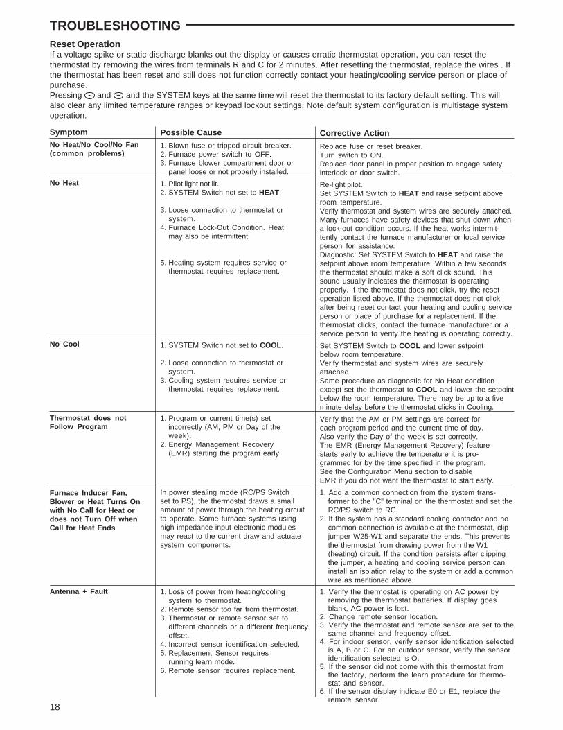
TROUBLESHOOTINGReset OperationIf a voltage spike or static discharge blanks out the display or causes erratic thermostat operation, you can reset thethermostat by removing the wires from terminals R and C for 2 minutes. After resetting the thermostat, replace the wires . Ifthe thermostat has been reset and still does not function correctly contact your heating/cooling service person or place ofpurchase.Pressing and and the SYSTEM keys at the same time will reset the thermostat to its factory default setting. This willalso clear any limited temperature ranges or keypad lockout settings. Note default system configuration is multistage systemoperation.
Symptom
No Heat/No Cool/No Fan(common problems)
No Heat
No Cool
Thermostat does notFollow Program
Furnace Inducer Fan,Blower or Heat Turns Onwith No Call for Heat ordoes not Turn Off whenCall for Heat Ends
Antenna + Fault
Corrective Action
Replace fuse or reset breaker.Turn switch to ON.Replace door panel in proper position to engage safetyinterlock or door switch.Re-light pilot.Set SYSTEM Switch to HEAT and raise setpoint aboveroom temperature.Verify thermostat and system wires are securely attached.Many furnaces have safety devices that shut down whena lock-out condition occurs. If the heat works intermit-tently contact the furnace manufacturer or local serviceperson for assistance.Diagnostic: Set SYSTEM Switch to HEAT and raise thesetpoint above room temperature. Within a few secondsthe thermostat should make a soft click sound. Thissound usually indicates the thermostat is operatingproperly. If the thermostat does not click, try the resetoperation listed above. If the thermostat does not clickafter being reset contact your heating and cooling serviceperson or place of purchase for a replacement. If thethermostat clicks, contact the furnace manufacturer or aservice person to verify the heating is operating correctly.Set SYSTEM Switch to COOL and lower setpointbelow room temperature.Verify thermostat and system wires are securelyattached.Same procedure as diagnostic for No Heat conditionexcept set the thermostat to COOL and lower the setpointbelow the room temperature. There may be up to a fiveminute delay before the thermostat clicks in Cooling.Verify that the AM or PM settings are correct foreach program period and the current time of day.Also verify the Day of the week is set correctly.The EMR (Energy Management Recovery) featurestarts early to achieve the temperature it is pro-grammed for by the time specified in the program.See the Configuration Menu section to disableEMR if you do not want the thermostat to start early.1. Add a common connection from the system trans-
former to the "C" terminal on the thermostat and set theRC/PS switch to RC.
2. If the system has a standard cooling contactor and nocommon connection is available at the thermostat, clipjumper W25-W1 and separate the ends. This preventsthe thermostat from drawing power from the W1(heating) circuit. If the condition persists after clippingthe jumper, a heating and cooling service person caninstall an isolation relay to the system or add a commonwire as mentioned above.
1. Verify the thermostat is operating on AC power byremoving the thermostat batteries. If display goesblank, AC power is lost.
2. Change remote sensor location.3. Verify the thermostat and remote sensor are set to the
same channel and frequency offset.4. For indoor sensor, verify sensor identification selected
is A, B or C. For an outdoor sensor, verify the sensoridentification selected is O.
5. If the sensor did not come with this thermostat fromthe factory, perform the learn procedure for thermo-stat and sensor.
6. If the sensor display indicate E0 or E1, replace theremote sensor.
18
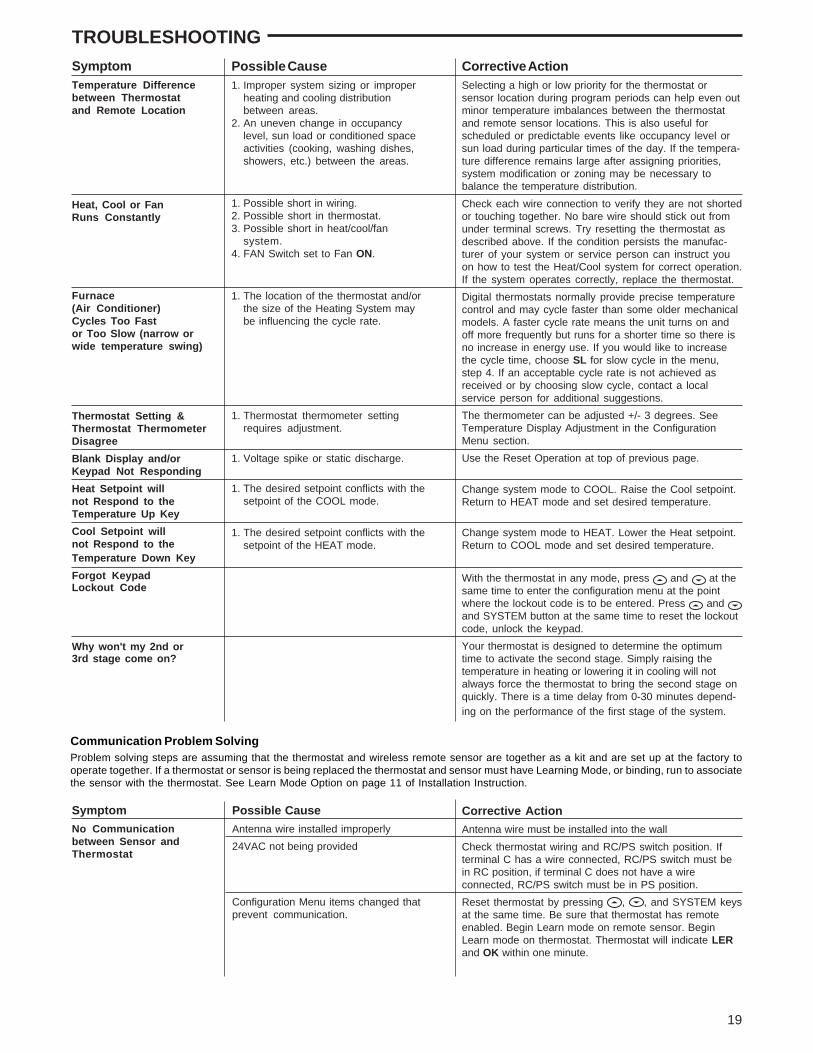
Possible Cause1. Improper system sizing or improper
heating and cooling distributionbetween areas.
2. An uneven change in occupancylevel, sun load or conditioned spaceactivities (cooking, washing dishes,showers, etc.) between the areas.
1. Possible short in wiring.2. Possible short in thermostat.3. Possible short in heat/cool/fan
system.4. FAN Switch set to Fan ON.
1. The location of the thermostat and/orthe size of the Heating System maybe influencing the cycle rate.
1. Thermostat thermometer settingrequires adjustment.
1. Voltage spike or static discharge.
1. The desired setpoint conflicts with thesetpoint of the COOL mode.
1. The desired setpoint conflicts with thesetpoint of the HEAT mode.
SymptomTemperature Differencebetween Thermostatand Remote Location
Heat, Cool or FanRuns Constantly
Furnace(Air Conditioner)Cycles Too Fastor Too Slow (narrow orwide temperature swing)
Thermostat Setting &Thermostat ThermometerDisagree
Blank Display and/orKeypad Not Responding
Heat Setpoint willnot Respond to theTemperature Up Key
Cool Setpoint willnot Respond to theTemperature Down Key
Forgot KeypadLockout Code
Why won't my 2nd or3rd stage come on?
Corrective ActionSelecting a high or low priority for the thermostat orsensor location during program periods can help even outminor temperature imbalances between the thermostatand remote sensor locations. This is also useful forscheduled or predictable events like occupancy level orsun load during particular times of the day. If the tempera-ture difference remains large after assigning priorities,system modification or zoning may be necessary tobalance the temperature distribution.Check each wire connection to verify they are not shortedor touching together. No bare wire should stick out fromunder terminal screws. Try resetting the thermostat asdescribed above. If the condition persists the manufac-turer of your system or service person can instruct youon how to test the Heat/Cool system for correct operation.If the system operates correctly, replace the thermostat.Digital thermostats normally provide precise temperaturecontrol and may cycle faster than some older mechanicalmodels. A faster cycle rate means the unit turns on andoff more frequently but runs for a shorter time so there isno increase in energy use. If you would like to increasethe cycle time, choose SL for slow cycle in the menu,step 4. If an acceptable cycle rate is not achieved asreceived or by choosing slow cycle, contact a localservice person for additional suggestions.The thermometer can be adjusted +/- 3 degrees. SeeTemperature Display Adjustment in the ConfigurationMenu section.Use the Reset Operation at top of previous page.
Change system mode to COOL. Raise the Cool setpoint.Return to HEAT mode and set desired temperature.
Change system mode to HEAT. Lower the Heat setpoint.Return to COOL mode and set desired temperature.
With the thermostat in any mode, press and at thesame time to enter the configuration menu at the pointwhere the lockout code is to be entered. Press and and SYSTEM button at the same time to reset the lockoutcode, unlock the keypad.Your thermostat is designed to determine the optimumtime to activate the second stage. Simply raising thetemperature in heating or lowering it in cooling will notalways force the thermostat to bring the second stage onquickly. There is a time delay from 0-30 minutes depend-ing on the performance of the first stage of the system.
TROUBLESHOOTING
19
Communication Problem SolvingProblem solving steps are assuming that the thermostat and wireless remote sensor are together as a kit and are set up at the factory tooperate together. If a thermostat or sensor is being replaced the thermostat and sensor must have Learning Mode, or binding, run to associatethe sensor with the thermostat. See Learn Mode Option on page 11 of Installation Instruction.
Symptom
No Communicationbetween Sensor andThermostat
Possible Cause
Antenna wire installed improperly24VAC not being provided
Configuration Menu items changed thatprevent communication.
Corrective Action
Antenna wire must be installed into the wallCheck thermostat wiring and RC/PS switch position. Ifterminal C has a wire connected, RC/PS switch must bein RC position, if terminal C does not have a wireconnected, RC/PS switch must be in PS position.Reset thermostat by pressing , , and SYSTEM keysat the same time. Be sure that thermostat has remoteenabled. Begin Learn mode on remote sensor. BeginLearn mode on thermostat. Thermostat will indicate LERand OK within one minute.

Corrective ActionAntenna wire must be installed into the wall
Thermostat and sensor must be at least 5 feet above thefloor
Relocate thermostat or sensor
Relocate thermostat or sensor away from obstacle
If thermostat is indicating that it is receiving, the remote istransmitting. If you wish to have the remote sensordisplay show Temperature and Transmitting icon, changethe User Configuration Menu, item 4 from OFF to On
TROUBLESHOOTING
White-Rodgers is a divisionof Emerson Electric Co.
The Emerson logo is atrademark and service mark of Emerson Electric Co.
www.white-rodgers.comwww.emersonclimate.com
HOMEOWNER HELP LINE: 1-800-284-2925
SymptomPoor Communicationbetween sensor andthermostat
Remote sensor displayshows only PWR and On.Transmitting icon does notappear. In Learn mode,Transmitting icon andLearn icon do not appear
Possible CauseAntenna were installed improperlyThermostat and/or sensor not at properheight
Thermostat or sensor may be too close to awireless device or noise producing deviceThermostat or sensor may have obstaclesin wallRemote sensor is configured to havedisplay OFF
Communication DiagnosticThe thermostat will monitor the integrity of the communication between the thermostat, receiver and wireless remote sensors. When thethermostat detects a potential communication problem, the LED will flash to indicate a failure code. The LED will flash at 1/2 second On/Off with a 2 second pause. If more than one error occurs, the highest priority warning will be shown until it is resolved. The indication ofthe codes is listed below in the highest priority order.
Possible Cause
Power Mode Switch S7 set to RC and common wire notconnected to C terminal.Receiver antenna not positioned properlyPoor remote sensor location or orientationNoisy environmentRadio interferring signalTo prevent this error indication press and hold RUN for 4seconds to override. Override will be cleared on power-up.Receiver not programmed (learned) to sensorOther remote sensor operating on same RF frequencychannelReceiver installed improperly
Receiver module inoperative
Remote sensor battery dead
Remote sensor has been moved or removed
Remote sensor battery dead
Remote sensor has been moved or removed
Local sensor temperature sensing circuit malfunction.
Code(Flashes)
1
2
3
4
5
6
7
Indication
24 VAC lost or not present (receiver will turn off and stopcommunication with wireless remote sensor)The receiver detected an invalid packet that fails CRCcheckThe receiver detected abnormal false tripping
Receiver detected unidentified packet that passes CRCcheck
Thermostat failed to communicate with receiver module
Indoor remote sensor not responding (Indoor sensor isenabled and thermostat has not received update for over30 minutes) thermostat will display Fault and antenna icon
Outdoor remote sensor not responding (Outdoor sensor isenabled and thermostat has not received update for over30 minutes) thermostat will display Fault and antenna icon
Local sensor faulty