quick selection guide coninvers - rde connectors & · pdf filesignal connectors • m23...
TRANSCRIPT

Quick Selection GuideSignal Connectors
• M23 Coupling
• Bayonet Coupling
Edition 03/02
CO
NIN
VER
S®

Signal C
onnectors • M23 • B
ayonetQ
uick Selection G
uide • Edition 03/02
Contact inserts male (pin)
PContact inserts female (socket)
S
1Insert with pin contacts numbering clockwise (mating face)
1Insert with socket contacts numbering counter clockwise (mating face)
2Insert with pin contacts numbering counter clockwise (mating face)
2Insert with socket contacts numbering clockwise (mating face)
C O N I N V E R S – P a r t N u m b e r
RC/UC/ TU-
RC
/UC
/TU
-Series In
sertsD
efinin
g th
e Insert o
f Co
nn
ectors
1 2 S 1 N 1 2T
he first 7 digits out of the 11 digit part number define the contact insert.
This applies for R
C, U
C and T
U connector series.
The standard coding is "N".Other coding options available on request.
Not all codings are available for all No. of positions.
Standard Versions
12 =Solder Cup
8A =Crimp Style(up to 17 pos./up to 0,75 mm2 )
RA =Crimp Style(16-19 pos./up to 1,0 mm2)
S2 =Screw Style(6, 7, 9 pos.)
22 =Dip Solder32 (PCB mounting) A2 for receptacles C2 in various
lengths
42 =IP67 unmatedK2 (12 pos. only)N2L2
Other on Request
06 6 Positions
07 7 Positions
09 9 Positions (8+1)
63 9 Positions (6+3)
12 12 Positions
2R 12 Pos. (11 + PE)
16 16 Positions
17 17 Positions
19 19 Pos. (16 + 3)
1R 19 Pos. (16 + 2 + PE)
Pin Socket
Number of Contacts(View: mating face)
Style of Contacts
Contact Insert Numbering
Contact Insert Coding
ContactTerminations

Vibration brake(CuZn only)
Receptacle round flange, front mounting, 6000 With hex. nut and gasket,
threading 6 mm length6R00 With hex. nut and gasket,
threading 10 mm length6100 With hex. nut and o-ring,
threading 6 mm length6300 With threading only PG13,5
6 mm length
1,5 mmsealing ringalternativeO-Ring
Coding channel 18,9Receptacle square flange, rear mounting,Shell material CuZn / GD-Zn *
4000 With gasket, 4 threads M2,5, CuZn4100 With gasket, 4 threads M3, CuZn4200 With o-ring, 4 threads M2,5, CuZn4300 With o-ring, 4 threads M3, CuZn4F00 With gasket, 4 threads M2,5, GD-Zn4E00 With gasket, 4 threads M3, GD-Zn4Z00 With o-ring, 4 threads M2,5, GD-Zn4D00 With o-ring, 4 threads M3, GD-Zn
5000 With gasket, 4 holes Ø 2,7 mm, CuZn5100 With gasket, 4 holes Ø 3,2 mm, CuZn5200 With o-ring, 4 holes Ø 2,7 mm, CuZn5300 With o-ring, 4 holes Ø 3,2 mm, CuZn5F00 With gasket, 4 holes Ø 2,7 mm, GD-Zn5E00 With gasket, 4 holes Ø 3,2 mm, GD-Zn5Z00 With o-ring, 4 holes Ø 2,7 mm, GD-Zn5D00 With o-ring, 4 holes Ø 3,2 mm, GD-Zn
Signal C
onnectors • M23 • B
ayonetQ
uick Selection G
uide • Edition 03/02
M23 R
C-S
eries Recep
taclesD
efinin
g th
e Sh
ell Style o
f Co
nn
ectors
The last 4 digits out of the 11 digit part num
ber define the body style.
C O N I N V E R S – P a r t N u m b e r
RC- 2 3 0 0
Receptacle round flange, rear mounting, H000 O-ring axial Receptacle square flange, front mounting,
Shell material CuZn / GD-Zn *2200 With gasket, 4 holes Ø 2,7 mm, CuZn2300 With gasket, 4 holes Ø 3,2 mm, CuZn2K00 With gasket, 4 holes Ø 2,7 mm, GD-Zn2S00 With gasket, 4 holes Ø 3,2 mm, GD-Zn
Receptacle square flange, front mountingY200 With gasket, 4 holes Ø 2,7 mmY300 With gasket, 4 holes Ø 3,2 mmYR00 With o-ring radial, 4 holes Ø 3,2 mmYF00 With o-ring axial, 4 holes Ø 3,2 mm
Receptacle square flange, front mountingWQ00 With o-ring radial, 4 holes Ø 2,7 mmWR00 With o-ring radial, 4 holes Ø 3,2 mmWS00 With o-ring axial, 4 holes Ø 2,7 mmWT00 With o-ring axial, 4 holes Ø 3,2 mm
Vibration brake(CuZn only) Gasket
1mm
O-Ring radialalternativeO-Ring axial
O-Ring
alternative 1mm gasket
A
A
B
B
see fig.
Asee fig.
Asee fig.
see fig.
see fig.
B
Asee fig.
see fig. B
see fig. B
B
see fig.
A
see fig.
A B A B
Asee fig.
see fig. B
A BA B
Contact insert can not be disassembled(shell material GD-Zn only)
*

53 57 E7 HA MA
4,0 5,0
2,5
3,2
3,6
3,8
4,1
4,3
4,6
4,9
5,2
5,5
5,8
6,2
6,6
7,0
7,4
7,7
6,0 7,5 8,5 10,0 11,0 NBRUniv.
FPMUniv.
58 50 U7 HB MB
A7 59 60 V7 HC MC
61 62 Q5 99 HD MD
54 56 P5 J8 HE ME
W7 X9 Y9 Z9 HF MF
X7 55 03 P8 HG MG
J9 G6 P6 HH MH
63 64 05 HJ MJ
84 49 04 JC HK MK
H7 N8 07 E6 HL ML
G5 NY Q6 HM MM
Q8 06 V5 HN MN
52 L6 HP MP
51 Q9 HQ MQ
98 J0 HR MR
D = Sealing ring inner dia.
d
Cable outer dia. = D1Washer
d = Shielding sleeve inner dia.
Signal C
onnectors • M23 • B
ayonetQ
uick Selection G
uide • Edition 03/02
Example for determining D1, d
C O N I N V E R S – P a r t N u m b e r
RC- 8 0 4 9
80 Cable connector with integrated cable gland,max 10,5 mm cable dia., IP 67
Q0 Cable connector with integrated cable gland,max 10,5 mm cable dia., IP 67, for rear mounting to use as a receptacle
T0 Cable connector with integrated cable gland,max 10,5 mm cable dia., IP 67
90 Cable connecting receptacle with integratedcable gland, max 10,5 mm cable dia., IP 67,fits into connector with coupling nut
Cable connector with integrated cable gland,max 10,5 mm cable dia., IP 67, for rear mounting to use as a receptacle
C0 With gasket, 4 threads M2,5C1 With gasket, 4 threads M3 C2 With o-ring, 4 threads M2,5 C3 With o-ring, 4 threads M3
M23 R
C-S
eries Sh
ielded
Defin
ing
the S
hell S
tyle of C
on
necto
rsT
he last 4 digits out of the 11 digit part number define the body style.
O-R
ing
radi
alal
tern
ativ
e1m
mG
aske
t
Diameter between cable bundle and the braiding = d
Outside diameter of cable = D1
Regarding the RC shielded connectors, the EMI accessoriesare defined by the last two digits as shown in the matrixbelow. This is not applicable to the UC / TU series.
Dimensions in mm
D =
D1
+ 2
mm
(ap
prox
.)Universal type: shielding disc / universalsealing ring for cable dia. up to 9,5 mm = EP

Signal C
onnectors • M23 • B
ayonetQ
uick Selection G
uide • Edition 03/02
Receptacle, rear mounting, with IP 68 cable gland, PG 7 to PG 13,5
GH00 PG 7 cable entry 4-6 mm dia.GI00 PG 9 cable entry 6-10 mm dia.GK00 PG 11 cable entry 8-12 mm dia.GL00 PG 13,5 cable entry 10-14 mm dia.
C O N I N V E R S – P a r t N u m b e r
RC- 1 L 0 0
Cable connector with standard cable gland,PG 7 to PG 13,5
Z400 PG 7 cable entry 4-6 mm dia.Z500 PG 9 cable entry 6-10 mm dia.Z600 PG 11 cable entry 8-12 mm dia.Z700 PG 13,5 cable entry 10-14 mm dia.
Receptacle, rear mounting, with standardcable gland, PG 7 to PG 13,5
G400 PG 7 cable entry 4-6 mm dia.G500 PG 9 cable entry 6-10 mm dia.G600 PG 11 cable entry 8-12 mm dia.G700 PG 13,5 cable entry 10-14 mm dia.
Cable connecting receptacle with standardcable gland, PG 7 to PG 13,5
7400 PG 7 cable entry 4-6 mm dia.7500 PG 9 cable entry 6-10 mm dia.7600 PG 11 cable entry 8-12 mm dia.7700 PG 13,5 cable entry 10-14 mm dia.
Cable connector with IP 68 cable gland, PG 7 to PG 13,5
ZH00 PG 7 cable entry 4-6 mm dia.ZI00 PG 9 cable entry 6-10 mm dia.ZK00 PG 11 cable entry 8-12 mm dia.ZL00 PG 13,5 cable entry 10-14 mm dia.
Cable connector with standard cable gland,PG 7 to PG 13,5
1400 PG 7 cable entry 4-6 mm dia.1500 PG 9 cable entry 6-10 mm dia.1600 PG 11 cable entry 8-12 mm dia.1700 PG 13,5 cable entry 10-14 mm dia.
Cable connector with IP 68 cable gland, PG 7 to PG 13,5
1H00 PG 7 cable entry 4-6 mm dia.1I00 PG 9 cable entry 6-10 mm dia.1K00 PG 11 cable entry 8-12 mm dia.1L00 PG 13,5 cable entry 10-14 mm dia.
Cable connecting receptacle with IP 68cable gland, PG 7 to PG 13,5
7H00 PG 7 cable entry 4-6 mm dia.7I00 PG 9 cable entry 6-10 mm dia.7K00 PG 11 cable entry 8-12 mm dia.7L00 PG 13,5 cable entry 10-14 mm dia.
M23 R
C-S
eries Un
shield
edD
efinin
g th
e Sh
ell Style o
f Co
nn
ectors
The last 4 digits out of the 11 digit part num
ber define the body style.
Further cable glands and metric threadings available on request

Signal C
onnectors • M23 • B
ayonetQ
uick Selection G
uide • Edition 03/02
80DU Cable connector with integrated cable gland,universal shielding, enlarged cable entry upto 14,5 mm dia., IP 67
C O N I N V E R S – P a r t N u m b e r
UC- 8 0 D U
Q0DU Receptacle, rear mounting, with integratedcable gland, universal shielding, enlargedcable entry up to 14,5 mm dia., IP 67
Receptacle (long version), rear mounting,with additional strain relief, Pg 13,5 or Pg 16, universal shielding, enlarged cableentry up to 14,5 mm dia., IP 67
Q3DU PG 13,5 cable entry 10-13,5 mm dia.QNDU PG 16 cable entry 12-14,5 mm dia.
Cable connecting receptacle (long version),with additional strain relief, Pg 13,5 or Pg 16, universal shielding, enlarged cableentry up to 14,5 mm dia., IP 67
F3DU PG 13,5 cable entry 10-13,5 mm dia.FNDU PG 16 cable entry 12-14,5 mm dia.
90DU Cable connecting receptacle with integratedcable gland, universal shielding, enlargedcable entry up to 14,5 mm dia., IP 67
T0DU Cable connector with integrated cable gland,universal shielding, enlarged cable entry upto 14,5 mm dia., IP 67
Cable connector (long version), with additional strain relief, Pg 13,5 or Pg 16,universal shielding, enlarged cable entry upto 14,5 mm dia., IP 67
N3DU PG 13,5 cable entry 10-13,5 mm dia.NNDU PG 16 cable entry 12-14,5 mm dia.
Cable connector (long version), with additional strain relief, Pg 13,5 or Pg 16,universal shielding, enlarged cable entry upto 14,5 mm dia., IP 67
R3DU PG 13,5 cable entry 10-13,5 mm dia.RNDU PG 16 cable entry 12-14,5 mm dia.
M23 U
C-S
eries Sh
ielded
Defin
ing
the S
hell S
tyle of C
on
necto
rsT
he last 4 digits out of the 11 digit part number define the body style.
Please order cable glands (IP 68 /double lever strain relief) separately
Further cable glands and metric threadings available on request
1
1 1
1
1
Signal C
onnectors • M23 • B
ayonetQ
uick Selection G
uide • Edition 03/02
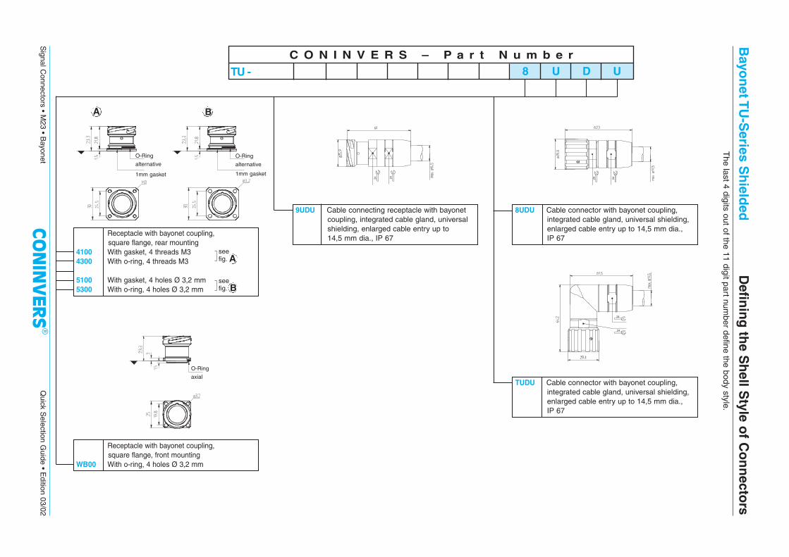
8UDU Cable connector with bayonet coupling, integrated cable gland, universal shielding,enlarged cable entry up to 14,5 mm dia., IP 67
C O N I N V E R S – P a r t N u m b e r
TU - 8 U D U
9UDU Cable connecting receptacle with bayonetcoupling, integrated cable gland, universalshielding, enlarged cable entry up to 14,5 mm dia., IP 67
TUDU Cable connector with bayonet coupling, integrated cable gland, universal shielding,enlarged cable entry up to 14,5 mm dia., IP 67
Bayo
net T
U-S
eries Sh
ielded
Defin
ing
the S
hell S
tyle of C
on
necto
rsT
he last 4 digits out of the 11 digit part number define the body style.
O-Ring
alternative
1mm gasket
O-Ring
alternative
1mm gasket
Receptacle with bayonet coupling, square flange, rear mounting
4100 With gasket, 4 threads M34300 With o-ring, 4 threads M3
5100 With gasket, 4 holes Ø 3,2 mm5300 With o-ring, 4 holes Ø 3,2 mm
O-Ring
axial
Receptacle with bayonet coupling, square flange, front mounting
WB00 With o-ring, 4 holes Ø 3,2 mm
Asee fig.
see fig. B
A B

RC/UC/TU-Series Technical Data
Mechanical Data
Shell materialMachined component by Copper-Zinc alloy (CuZn) , die cast component by Zinc (GD-Zn)Shell platingNickel (standard), on request: black chromated, plastic moldedInsulator/flammabilityThermoplastic Polyester (PBT), Polyamid (PA 66), Polycarbonat (PC)/UL 94 V0Contact materialCopper-Zinc alloy (CuZn)Contact platingNickel (Ni) with Gold (Au) and passivatedContact terminationSolder cup, dip solder, crimp type, screw typeSeal and O-RingFluor rubber (FPM) GasketPerbunan (NBR-stiffened gasket), Fluor rubber (FPM)Temperature range-40°C/+125°C (long term temperature)Cable entry RC-SeriesEMI version: outer dia. of cable 2 - 10,5 mm, without EMI protection: outer dia. of cable 4 - 14 mmCable entry UC/TU-SeriesEMI version: outer dia. of cable 2 - 14,5 mmMating method Mating cycles mechan.RC/UC-Series: threaded coupling M23; TU-Series: bayonet coupling Standard: 50, higher on request Protection classIP 67 mated, for EMI versionsIP 65 - IP 68 mated, being subject to cable gland used, for versions without EMI protectionApproval RC-SeriesUL-recognized File No 153698 (M) Underwriters Laboratories Inc.®
Electrical Data
Number of positions6, 7 9(8+1) 9(6+3) 12 16 17 19(16+3)
12(11+PE) 16(15+PE) 17(16+PE) 19(16+2+PE)12 Hybrid
Contact 6, 7 8 + 1 6 + 3 11, 12 15, 16 16, 17 16 + 3Contact dia. (mm) 2 1 2 1 2 1 1 1 1 1,5Rated current (A) 20 8 20 8 20 8 8 8 8 10
Rated voltage (V AC eff. / DC) 250 150 150 150 150 150 150
Test voltage (kV AC) 2,5 1,5 1,5 1,5 1,5 1,5 1,5
Overvoltage category 1) II II II II II II IIInsulation resistance (Ω) ≥1016 ≥1016 ≥1012 ≥1012 ≥1012 ≥1012 ≥1012
Contact resistance (mΩ) ≤3 ≤3 ≤3 ≤3 ≤3 ≤3 ≤3Pollution degree acc. to IEC 664-1 2 (31) 2 (31) 2 (31) 2 (31) 2 (31) 2 (31) 2 (31)
1) Reference: DIN EN 61984:2001
AD
-000
9-02
Fax to: +49 (0)70 32/92 74-330 We desire a technical consultation regarding the products:
Description Part No.
Description Part No.
Description Part No.
Description Part No.
Please send us the CONINVERS Short Form Catalog
Contact Person Dept.
Company
Zip, City Street
Phone/Fax E-mail
Heisenbergstr. 1 • D-71083 HerrenbergTel. +49 (0) 70 32/92 74-0 • Fax +49 (0)70 32/92 74-330