quick start guide - getscw · properly connect an rj45 connector to bare wire cat5e or cat6 cable...
TRANSCRIPT

Quick Start Guide
Fall 2016 Ver. 2.0

2
Table of ContentsBench Testing Guide 1Creating Your Own Ethernet Cabling 3RJ45 Weatherproofing Guide 6Weatherproofing Mounts 8Preamble to Recording 10Setting Up Recording 12Email Notifications 15Infrared Guide 17Store Policies 21FAQ 23

3
Thank You from SCWOn behalf of the entire SCW team, we sincerely thank you for your purchase! If you have any questions or need some assistance please don’t hesitate to contact us.
This quick start guide is intended to get your system up and running with the basic necessities like cabling, weatherproofing, recording, motion and more. This guide is not intended to replace the full manuals available at our full support portal at www.scwguide.com which goes into greater detail and covers more advanced options of the system.
Contact InfoToll Free: 866-414-2553
www.security-camera-warehouse.com
Support Portal: www.scwguide.com
Email: [email protected]
Essential InfoDefault Recorder Password: 12345scw or 12345
Default Camera Password: 12345 or the password of the NVR it was plugged into
11
Bench Testing Guide
When your system arrives, the first step before installation is to do a “bench test”. Bench testing allows you to test the equipment prior to installation. This can save both time and headache down the road, as you can ensure cameras work prior to being mounted.
Bench testing may also be used to troubleshoot cameras that experienced connectivity issues or go down in order to isolate the issue.
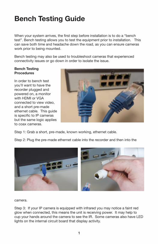
Bench Testing Procedures
In order to bench test you’ll want to have the recorder plugged and powered on, a monitor with HDMI or VGA connected to view video, and a short pre-made ethernet cable. This guide is specific to IP cameras but the same logic applies to coax cameras.
Step 1: Grab a short, pre-made, known working, ethernet cable.
Step 2: Plug the pre-made ethernet cable into the recorder and then into the
camera.
Step 3: If your IP camera is equipped with infrared you may notice a faint red glow when connected, this means the unit is receiving power. It may help to cup your hands around the camera to see the IR. Some cameras also have LED lights on the internal circuit board that display activity.
2
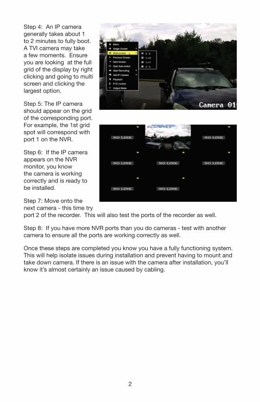
Step 4: An IP camera generally takes about 1 to 2 minutes to fully boot. A TVI camera may take a few moments. Ensure you are looking at the full grid of the display by right clicking and going to multi screen and clicking the largest option.
Step 5: The IP camera should appear on the grid of the corresponding port. For example, the 1st grid spot will correspond with port 1 on the NVR.
Step 6: If the IP camera appears on the NVR monitor, you know the camera is working correctly and is ready to be installed.
Step 7: Move onto the next camera - this time try port 2 of the recorder. This will also test the ports of the recorder as well.
Step 8: If you have more NVR ports than you do cameras - test with another camera to ensure all the ports are working correctly as well.
Once these steps are completed you know you have a fully functioning system. This will help isolate issues during installation and prevent having to mount and take down camera. If there is an issue with the camera after installation, you’ll know it’s almost certainly an issue caused by cabling.
3
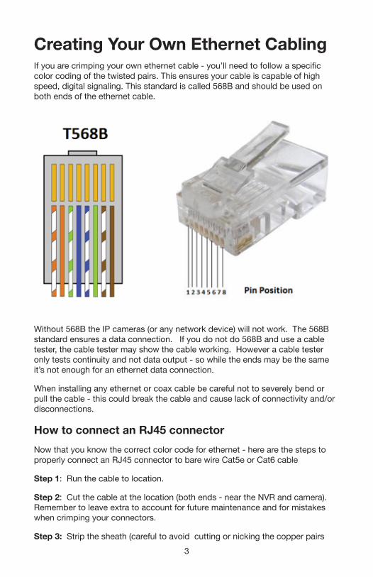
Creating Your Own Ethernet CablingIf you are crimping your own ethernet cable - you’ll need to follow a specific color coding of the twisted pairs. This ensures your cable is capable of high speed, digital signaling. This standard is called 568B and should be used on both ends of the ethernet cable.
Without 568B the IP cameras (or any network device) will not work. The 568B standard ensures a data connection. If you do not do 568B and use a cable tester, the cable tester may show the cable working. However a cable tester only tests continuity and not data output - so while the ends may be the same it’s not enough for an ethernet data connection.
When installing any ethernet or coax cable be careful not to severely bend or pull the cable - this could break the cable and cause lack of connectivity and/or disconnections.
How to connect an RJ45 connectorNow that you know the correct color code for ethernet - here are the steps to properly connect an RJ45 connector to bare wire Cat5e or Cat6 cable
Step 1: Run the cable to location.
Step 2: Cut the cable at the location (both ends - near the NVR and camera). Remember to leave extra to account for future maintenance and for mistakes when crimping your connectors.
Step 3: Strip the sheath (careful to avoid cutting or nicking the copper pairs
4
inside the Cat5e connector)
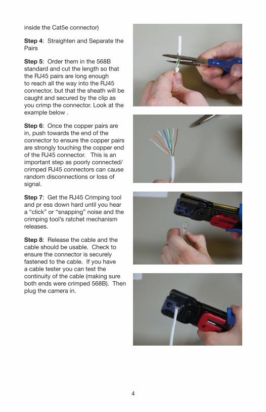
Step 4: Straighten and Separate the Pairs
Step 5: Order them in the 568B standard and cut the length so that the RJ45 pairs are long enough to reach all the way into the RJ45 connector, but that the sheath will be caught and secured by the clip as you crimp the connector. Look at the example below .
Step 6: Once the copper pairs are in, push towards the end of the connector to ensure the copper pairs are strongly touching the copper end of the RJ45 connector. This is an important step as poorly connected/crimped RJ45 connectors can cause random disconnections or loss of signal.
Step 7: Get the RJ45 Crimping tool and pr ess down hard until you hear a “click” or “snapping” noise and the crimping tool’s ratchet mechanism releases.
Step 8: Release the cable and the cable should be usable. Check to ensure the connector is securely fastened to the cable. If you have a cable tester you can test the continuity of the cable (making sure both ends were crimped 568B). Then plug the camera in.
5
Cable TroubleshootingIf you are having connectivity issues after installation - you may need to recheck the RJ45 connections to make sure this guide was followed correctly. If it continues to have issues and you bench tested the cameras - you may have bent/damaged the cable sometime during installation which may require you to re-run the cable.
Finally, the max distance of ethernet is 100 meters, or about 320FT. Any run going above 100 meters may not work or may suffer packet loss which results in dropped signal from the camera and disconnections. If you are running a cable longer than 320FT then you will need a PoE extender or a switch before the 320 foot mark.
If you get stuck on any of these steps please contact the SCW support team!
6
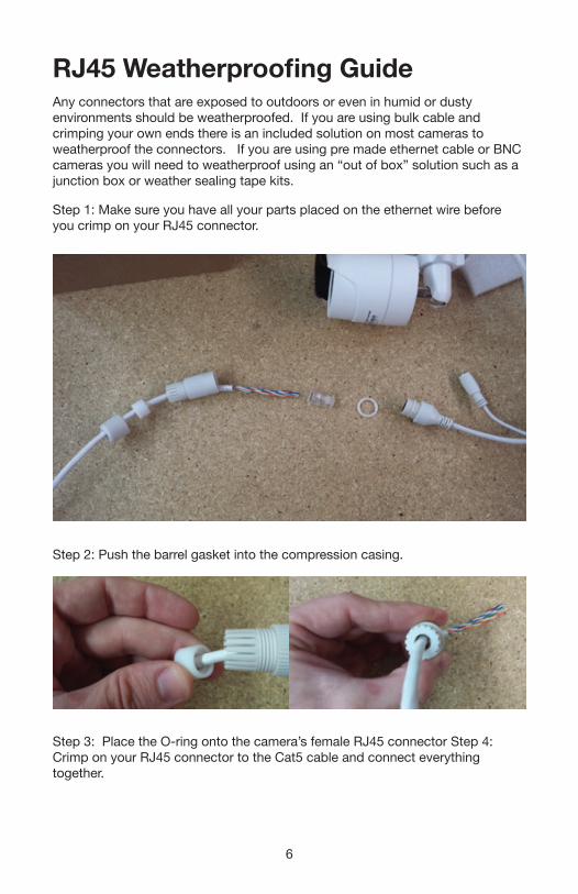
RJ45 Weatherproofing GuideAny connectors that are exposed to outdoors or even in humid or dusty environments should be weatherproofed. If you are using bulk cable and crimping your own ends there is an included solution on most cameras to weatherproof the connectors. If you are using pre made ethernet cable or BNC cameras you will need to weatherproof using an “out of box” solution such as a junction box or weather sealing tape kits.
Step 1: Make sure you have all your parts placed on the ethernet wire before you crimp on your RJ45 connector.
Step 2: Push the barrel gasket into the compression casing.
Step 3: Place the O-ring onto the camera’s female RJ45 connector Step 4: Crimp on your RJ45 connector to the Cat5 cable and connect everything together.
7
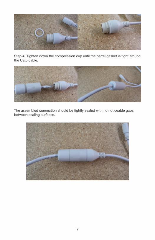
Step 4: Tighten down the compression cup until the barrel gasket is tight around the Cat5 cable.
The assembled connection should be tightly sealed with no noticeable gaps between sealing surfaces.
8
Weatherproofing MountsIf you are installing cameras outdoors or even in humid/dusty environments you’ll need to properly protect your cameras and equipment. Equipment damaged from improper weather proofing is not covered under warranty. For more information on warranty coverage check the warranty section.
General Weatherproofing GuidelinesStep 1: Ensure that connectors of the cable are weatherproofed if they are outdoors or in humid/dusty environments. This will prevent any kind of moisture or dust intrusion into the RJ45/BNC connector.
For IP cameras follow the RJ45 guide. For BNC cameras you’ll want to use a water sealed junction box or other “out of box” weatherproofing solution.
Improper weatherproofing of the connectors is the most common cause of failure for cameras and cable.
Step 2: Pay close attention to the specs listed on the product page as far as relative humidity, temperature ranges, etc. If the temperature drops below recommended specs it will temporarily impact image quality and the operation of the camera. If the temperature goes above it can permanently damage the equipment.
Step 3: Ensure proper weather proofing of the camera type.
General Guidelines for all modelsIP66 rating covers the following:
Water projected in powerful jets (12.5 mm nozzle) against the enclosure from any direction shall have no harmful effects.
Test duration: at least 3 minutes Water volume: 100 liters per minute Pressure: 100 kPa at distance of 3 m
In summary - this means that all IP66 rated cameras are completely weatherproof and can also withstand quite a bit of high pressure water for short amount of times.
In Real World: This means simple things like not putting cameras right under gutter/water drainage as the constant high pressure water could break the seals, as well as avoiding high pressure washers to clean, etc.
Bullet Cameras: On bullet cameras make sure the gap between the wall and the base of the camera is even. If there are gaps from uneven wall (brick/tile/etc) use silicon or some kind of sealing agent to prevent water ingress.
Dome Cameras: The IP66 Rating on Dome cameras relies on the base of the camera being completely sealed off from the elements and the screws
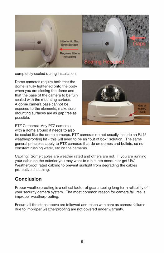
9
completely sealed during installation.
Dome cameras require both that the dome is fully tightened onto the body when you are closing the dome and that the base of the camera to be fully sealed with the mounting surface. A dome camera base cannot be exposed to the elements, make sure mounting surfaces are as gap free as possible.
PTZ Cameras: Any PTZ cameras with a dome around it needs to also be sealed like the dome cameras. PTZ cameras do not usually include an RJ45 weatherproofing kit - this will need to be an “out of box” solution. The same general principles apply to PTZ cameras that do on domes and bullets, so no constant rushing water, etc on the cameras.
Cabling: Some cables are weather rated and others are not. If you are running your cable on the exterior you may want to run it into conduit or get UV/Weatherproof rated cabling to prevent sunlight from degrading the cables protective sheathing.
ConclusionProper weatherproofing is a critical factor of guaranteeing long term reliability of your security camera system. The most common reason for camera failures is improper weatherproofing.
Ensure all the steps above are followed and taken with care as camera failures due to improper weatherproofing are not covered under warranty.
10
Preamble to RecordingBefore setting up recording, you will want to configure the following items.
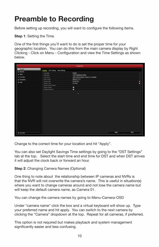
Step 1: Setting the Time
One of the first things you’ll want to do is set the proper time for your geographic location. You can do this from the main camera display by Right Clicking - Click on Menu - Configuration and view the Time Settings as shown below.
Change to the correct time for your location and hit “Apply”.
You can also set Daylight Savings Time settings by going to the “DST Settings” tab at the top. Select the start time and end time for DST and when DST arrives it will adjust the clock back or forward an hour.
Step 2: Changing Camera Names (Optional)
One thing to note about the relationship between IP cameras and NVRs is that the NVR will not overwrite the camera’s name. This is useful in situation(s) where you want to change cameras around and not lose the camera name but will keep the default camera name, as Camera 01.
You can change the camera names by going to Menu-Camera-OSD
Under “camera name” click the box and a virtual keyboard will show up. Type your preferred name and hit apply. You can switch to the next camera by clicking the “Camera” dropdown at the top. Repeat for all cameras, if preferred.
This option is not required but makes playback and system management significantly easier and less confusing.

11
12
RJ45 Camera CorrosionAs covered in the previous pages, weatherproofing your ethernet (RJ45) connector plays a key role in keeping your camera working reliably through the years. The consequence of improper weatherproofing is corrosion. Corrosion caused by improper weatherproofing or failure to weatherproof is not covered under warranty, for more information check the warranty section of this guide.
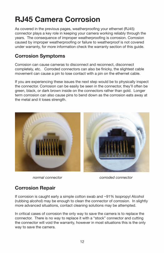
Corrosion SymptomsCorrosion can cause cameras to disconnect and reconnect, disconnect completely, etc. Corroded connectors can also be finicky, the slightest cable movement can cause a pin to lose contact with a pin on the ethernet cable.
If you are experiencing these issues the next step would be to physically inspect the connector. Corrosion can be easily be seen in the connector, they’ll often be green, black, or dark brown inside on the connectors rather than gold. Longer term corrosion can also cause pins to bend down as the corrosion eats away at the metal and it loses strength.
Corrosion RepairIf corrosion is caught early a simple cotton swab and ~91% Isopropyl Alcohol (rubbing alcohol) may be enough to clean the connector of corrosion. In slightly more advanced situations, contact cleaning solutions may be attempted.
In critical cases of corrosion the only way to save the camera is to replace the connector. There is no way to replace it with a “stock” connector and cutting the connector will void the warranty, however in most situations this is the only way to save the camera.
normal connector corroded connector
13
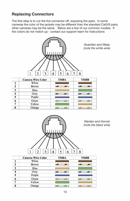
Replacing ConnectorsThe fi rst step is to cut the the connector off , exposing the pairs. In some cameras the color of the jackets may be diff erent than the standard Cat5/6 pairs, other cameras may be the same. Below are a few of our common models. If the colors do not match up - contact our support team for instructions
Guardian and Wasp (note the white wire)
Warden and Hornet (note the black wire)
14
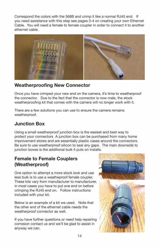
Correspond the colors with the 568B and crimp it like a normal RJ45 end. If you need assistance with this step see pages 3-4 on creating your own Ethernet Cable. You will need a female to female coupler in order to connect it to another ethernet cable.
Weatherproofing New ConnectorOnce you have crimped your new end on the camera, it’s time to weatherproof the connector. Due to the fact that the connector is now male, the stock weatherproofing kit that comes with the camera will no longer work with it.
There are a few solutions you can use to ensure the camera remains weatherproof.
Junction BoxUsing a small weatherproof junction box is the easiest and best way to protect your connectors A junction box can be purchased from many home improvement stores and are essentially plastic cases around the connectors. Be sure to use weatherproof silicon to seal any gaps. The main downside to junction boxes is the additional bulk it puts on installs.
Female to Female Couplers (Weatherproof)One option to attempt a more stock look and use less bulk is to use a weatheproof female coupler. These kits vary from manufacturer to manufacturer, in most cases you have to put one end on before crimping the RJ45 end on. Follow instructions included with your kit.
Below is an example of a kit we used. Note that the other end of the ethernet cable needs the weatherproof connector as well.
If you have further questions or need help repairing corrosion contact us and we’ll be glad to assist in anyway we can.
15
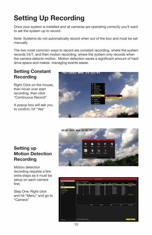
Setting Up RecordingOnce your system is installed and all cameras are operating correctly you’ll want to set the system up to record.
Note: Systems do not automatically record when out of the box and must be set manually
The two most common ways to record are constant recording, where the system records 24/7, and then motion recording, where the system only records when the camera detects motion. Motion detection saves a significant amount of hard drive space and makes managing events easier.
Setting Constant RecordingRight Click on the mouse, then hover over start recording, then click “Continuous Record”
A popup box will ask you to confirm, hit “Yes”
Setting up Motion Detection RecordingMotion detection recording requires a few extra steps as it must be setup on each camera first.
Step One: Right click and hit “Menu” and go to “Camera”
16
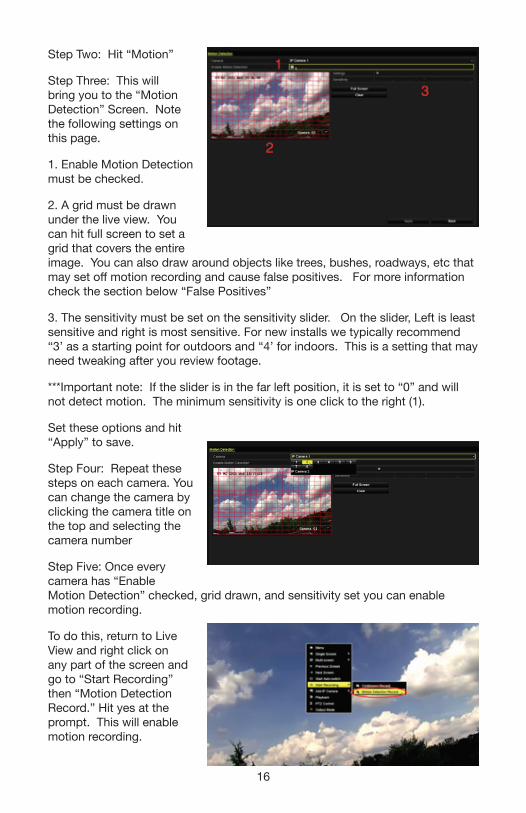
Step Two: Hit “Motion”
Step Three: This will bring you to the “Motion Detection” Screen. Note the following settings on this page.
1. Enable Motion Detection must be checked.
2. A grid must be drawn under the live view. You can hit full screen to set a grid that covers the entire image. You can also draw around objects like trees, bushes, roadways, etc that may set off motion recording and cause false positives. For more information check the section below “False Positives”
3. The sensitivity must be set on the sensitivity slider. On the slider, Left is least sensitive and right is most sensitive. For new installs we typically recommend “3’ as a starting point for outdoors and “4’ for indoors. This is a setting that may need tweaking after you review footage.
***Important note: If the slider is in the far left position, it is set to “0” and will not detect motion. The minimum sensitivity is one click to the right (1).
Set these options and hit “Apply” to save.
Step Four: Repeat these steps on each camera. You can change the camera by clicking the camera title on the top and selecting the camera number
Step Five: Once every camera has “Enable Motion Detection” checked, grid drawn, and sensitivity set you can enable motion recording.
To do this, return to Live View and right click on any part of the screen and go to “Start Recording” then “Motion Detection Record.” Hit yes at the prompt. This will enable motion recording.

17
False Positives and Motion DetectionMotion Detection works by detecting pixel changes in the image. The more the pixels change the more likely it is to trigger motion detection. To understand motion detection better you should understand what options you can tweak on motion.
A “false positive” is a motion event that isn’t capturing something important, such a bugs, branches, light changes, etc. You can reduce, but not completely eliminate the amount of false positives by tweaking the motion settings. Refer to step three above in order to adjust the grid and sensitivity settings to reduce false positives.
The other most common reason for false alerts is bugs at night. Insects get attracted to the infrared light for the same reason they get attracted to any other normal light. For more information and ways to reduce bug issues on cameras check the Infrared Section later in the guide.
18
Email Notifi cationsYour recorder has the ability to send email notifi cations on multiple event types, including:
• Motion Detection (Guide Below)• Video/Signal Loss• Video Tampering• Exceptions (Hard Drive Errors, etc)
And more - check the full manuals at www.scwguide.com for more information on how to set up some of these.
Email Notifi cations are sent from an email you provide. These are direct, point to point notifi cations that are very fast and reliable. Email notifi cations also have the option of including 3 attached screenshots. We typically recommend email notifi cations for the speed of the alert and the reliability.
Email notifi cations do require you to BYOE or Bring Your Own Email to send and receive the emails. You can use your own email you currently use or create a brand new one to send.
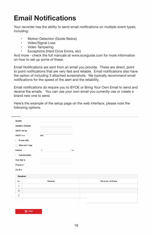
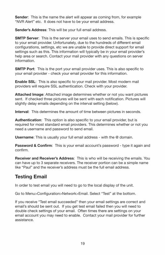
Here’s the example of the setup page on the web interface, please note the following options.
19
Sender: This is the name the alert will appear as coming from, for example “NVR Alert” etc. It does not have to be your email address.
Sender’s Address: This will be your full email address.
SMTP Server: This is the server your email uses to send emails. This is specific to your email provider. Unfortunately, due to the hundreds of different email configurations, settings, etc we are unable to provide direct support for email settings such as this. This information will typically be in your email provider’s help area or search. Contact your mail provider with any questions on server information.
SMTP Port: This is the port your email provider uses. This is also specific to your email provider - check your email provider for this information.
Enable SSL: This is also specific to your mail provider. Most modern mail providers will require SSL authentication. Check with your provider.
Attached Image: Attached image determines whether or not you want pictures sent. If checked three pictures will be sent with each notification. Pictures will slightly delay emails depending on the interval setting (below).
Interval: This determines the amount of time between pictures in seconds.
Authentication: This option is also specific to your email provider, but is required for most standard email providers. This determines whether or not you need a username and password to send email.
Username: This is usually your full email address - with the @ domain.
Password & Confirm: This is your email account’s password - type it again and confirm.
Receiver and Receiver’s Address: This is who will be receiving the emails. You can have up to 3 separate receivers. The receiver portion can be a simple name like “Paul” and the receiver’s address must be the full email address.
Testing EmailIn order to test email you will need to go to the local display of the unit.
Go to Menu>Configuration>Network>Email. Select “Test” at the bottom.
If you receive “Test email succeeded” then your email settings are correct and email’s should be sent out. If you get test email failed then you will need to double check settings of your email. Often times there are settings on your email account you may need to enable. Contact your mail provider for further assistance.
20
Infrared GuideInfrared is almost invisible thermal light that helps illuminate low light areas. Infrared works great because it’s mostly invisible by human eyes - allowing low light footage without lighting the property using conventional lighting.
Infrared light does have a small, light red glow on the LEDs. This is normal and is part of the wavelength IR cameras are on. Cameras that advertise not having the glow usually use a far less effective range of infrared. Most customers use the red glow as a deterrent for theft.
Infrared (IR) does have limitations and issues to be aware of during installation. Most underperforming or infrared issues are the result of improper installation positions or other simple fixes.
Reflectiveness of InfraredInfrared is a very reflective light source, so positioning a camera where reflections or “bounceback” doesn’t occur is imperative.
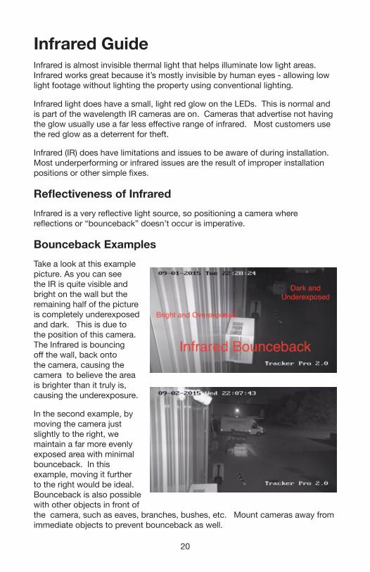
Bounceback ExamplesTake a look at this example picture. As you can see the IR is quite visible and bright on the wall but the remaining half of the picture is completely underexposed and dark. This is due to the position of this camera. The Infrared is bouncing off the wall, back onto the camera, causing the camera to believe the area is brighter than it truly is, causing the underexposure.
In the second example, by moving the camera just slightly to the right, we maintain a far more evenly exposed area with minimal bounceback. In this example, moving it further to the right would be ideal. Bounceback is also possible with other objects in front of the camera, such as eaves, branches, bushes, etc. Mount cameras away from immediate objects to prevent bounceback as well.
21
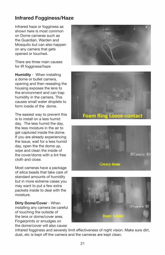
Infrared Fogginess/HazeInfrared haze or fogginess as shown here is most common on Dome cameras such as the Guardian, Warden and Mosquito but can also happen on any camera that gets opened or touched.
There are three main causes for IR fogginess/haze
Humidity - When installing a dome or bullet camera, opening and then resealing the housing exposes the lens to the environment and can trap humidity in the camera. This causes small water droplets to form inside of the dome.
The easiest way to prevent this is to install on a less humid day. The less humid the day, the less moisture in the air to get captured inside the dome. If you are already experiencing the issue, wait for a less humid day, open the the dome up, wipe and clean the inside of the cover/dome with a lint free cloth and close.
Most cameras have a package of silica beads that take care of standard amounts of humidity but in more extreme cases you may want to put a few extra packets inside to deal with the moisture.
Dirty Dome/Cover - When installing any camera be careful of touching the outside of the lens or dome/cover area. Fingerprints or smudges on the dome/cover will also cause infrared fogginess and severely limit effectiveness of night vision. Make sure dirt, dust, etc is kept off the camera and the cameras are kept clean.
22
Model Specific Rings - All cameras need to be completely tightened to ensure the infrared is working. Most dome cameras also have a light-proof foam ring around the lens to prevent the IR from leaking in on the lens/sensor. Make sure each camera is fully tightened and that the foam ring is touching the glass.
Infrared & Insects - Infrared, like any light source, attracts insects. Insects can have a surprisingly large impact on infrared
Insects can cause infrared bounce back, reducing quality like the above images show.
Insects more commonly cause issues by setting motion detection off during the night.
There is no specific way to prevent bugs from setting off motion detection because the bugs get so close to the camera’s sensor it appears be a large object.
The simplest fix for insects is to keep another light on. A front porch light or a flood light in the area will typically attract the bugs to that light and away from the camera. This fixes the issue for the majority of users.
License Plates & IR
License plate recognition even in broad daylight can be challenging - There are various factors that are involved in such as speed of vehicle, angle of the car, frames per second on the camera, etc.
During nighttime this challenge is increased exponentially. Beyond the standard factors you have to deal with IR and the reflectiveness of most license plates.
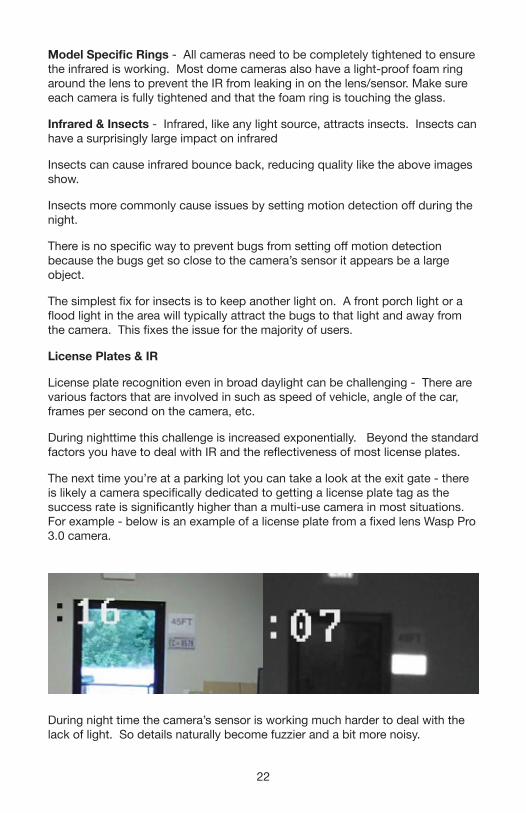
The next time you’re at a parking lot you can take a look at the exit gate - there is likely a camera specifically dedicated to getting a license plate tag as the success rate is significantly higher than a multi-use camera in most situations. For example - below is an example of a license plate from a fixed lens Wasp Pro 3.0 camera.
During night time the camera’s sensor is working much harder to deal with the lack of light. So details naturally become fuzzier and a bit more noisy.
23
The biggest issue however is the reflection of the license plate with the infrared. Depending on the angle the light hits the license plate the license plate will reflect significantly.
The amount of reflection will greatly depend on the angle of light.
Potential Solutions
Area Lighting and Infrared Off - Think of IR as a flashlight, it’s a high powered beam of light and any light (especially infrared lighting) will reflect against reflective objects.
The license plate recognition success rate will go up exponentially with IR off. With IR off you no longer have to deal with reflections.
This will require sufficient lighting around the area license plate recognition is required.
Stop Gate - If license plate recognition is absolutely critical to the facility - having a stop gate or a significant speed bump to stop/slow down cars is another way of increasing the success rate.
Smart IR - If area lighting is not a possibility - Smart IR may have a minor effect. Smart IR will tone down the IR if it detects reflections. However in most cases the reflectiveness of license plates is too much even on low powered IR and Smart IR isn’t all that useful.
ConclusionLicense plate recognition tests a camera’s limit better than anything. We recommend at least 1080p cameras for consistent levels of recognition. For long ranges you’ll need both high resolution and high levels of zoom with area lighting.
24
Store PoliciesReturns (Non Defective Items)Customers may return any new SCW equipment within 30 days of the order date.
If you have chosen to return your equipment within the 30 day return period, please contact SCW for an RMA number and RMA sheet to be included with your return. Failure to get an RMA may result in the return being sent back, delays in refund, and/or a restocking fee.
Please include all original accessories and packaging. Also, be sure to double box and preserve any original packaging/boxes/etc. Do not place return labels or any writing on product boxes. Damaged product packaging may result in a restocking fee. For more info check our full return policy at https://www.security-camera-warehouse.com/store-returns.php
Note: Return shipping is not covered for non defective items.
Warranty CoverageWe want our warranty coverage to be as simple as possible, so to simply put it, if any SCW equipment fails that was properly installed - we will repair or replace it within the warranty period.
However there are exceptions to this including:
The following situations void the product warranty: Opening the housing of any camera with a fixed lens (excluding domes designed to be opened). Cutting the connectors off any equipment. Adding 3rd party software to a DVR without prior approval from our technical support department.
Damage caused by the fault of the installer or customer with or without their knowledge (for example dropping or breaking the product, improper voltage, failing to waterproof connections or improper installation). Lightning strikes, physical damage due to dropping or improperly mounting the devices are not covered, or any unconventional or unauthorized use of the product. We cannot warranty any used cable.
Equipment that is used in environments beyond the recommended specifications will also void the warranty.
Troubleshooting PolicyIf you believe the equipment that you received is defective, the first step in fixing your issue is to contact the SCW support staff who will troubleshoot the problem to determine if a fix is possible. We may ask you to bench test the camera again, or ask you to send pictures to [email protected]
Defective Product Repair/Replacement
25
If an SCW technician has determined your product is faulty and requires a replacement you will have two methods of replacement, either a standard repair or an advance exchange.
Standard Repair: In this option, you’ll get a prepaid label to ship the defective product back to SCW. From here we’ll test and either repair or exchange the defective product and ship the product back to you.
Advanced Exchange: With an advance exchange we’ll ship you a replacement first, and then you ship back the defective product. Limiting your downtime. In order to process an advance exchange, we’ll need to take down a valid Debit or Credit card and put a hold charge for the cost of the product. The hold charge will be lifted when the defective product is received.
Note: Advance Exchange may not be available on all products and will depend on availability of the product.
Shipping Speeds for RMAAll advance replacements after 30 days from the order date will be shipped UPS Ground. All advanced replacements prior to 30 days after order date will be shipped at the same speed of the original order.
If you’d prefer a faster shipping option you will be required to pay the cost of your requested shipping speed.
International WarrantyAll products outside of the US carry the same warranty. However shipping charges aren’t covered outside of the US.
Replacement ConditionItems unable to be repaired or items replaced under advance exchange may be replaced with open box or refurbished items. They may feature minor cosmetic defects such as small scratches or marks.
Replacement items continue the balance of warranty from the original item. For example, if your item fails at 12 months and the item had a 36 month warranty, your replacement will carry on the remaining 24 months and not reset the warranty timer.

26
FAQListed below are commonly asked questions about the system ranging from installation to common icons, issues, etc.
Physical Installation FAQs• What’s this DC12V connector on my IP camera?
The DC12V connector is only necessary if you are not using PoE. If you have a PoE NVR you can ignore and tuck this cable away. Do not cut this off as doing so will void your warranty.
• How long can I run Ethernet cable?
100 meters or about 320 FT. If you have longer runs you’ll need to use a PoE extender.
• How long can I run coax cable?
For TVI cameras you can run up to 1500 feet. Avoid any electrical lines or areas that may cause interference. DC12V power can only go 300FT with analog.
• What are these red (or sometimes blue) cables in the accessory box?
They are SATA cables. SATA cables are cables for hard drives if you ever install additional drives.
• Why didn’t my recorder come with a remote?
At the moment remotes are quickly being phased off the product, the local user interface of the recorders is a mouse based UI. Most menus and options are either not possible to configure with a remote or very difficult to do so. If you need the range of a remote you can use any HID compliant wireless mouse. HID means it has a USB dongle with it and that it does not require any software to function.
27
User Interface FAQs• What is the default password?
Please check the front page of this Quickstart guide. On most equipment it will be 12345scw or 12345
• What happens if the hard drive gets full?
By default all recorders will begin overwriting the oldest footage in real time so the recording will not stop. Think of it like a recycling symbol it will continue to overwrite footage.
• What happens if I forget the password?
Due to strict security measures on the equipment a password reset will require you to have a computer on the same local network as the recorder. From there we can generate an individual reset code based on the day, device, and serial number. In rare cases password resets could take up to 2-3 business days. If you do not have the system on a local network or have a display connected, it will need to be sent to SCW for reset.
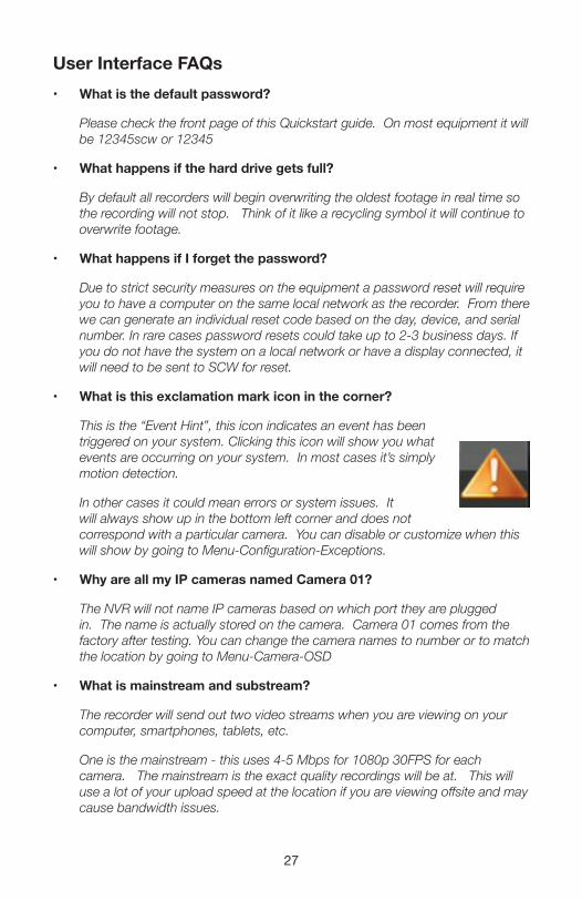
• What is this exclamation mark icon in the corner?
This is the “Event Hint”, this icon indicates an event has been triggered on your system. Clicking this icon will show you what events are occurring on your system. In most cases it’s simply motion detection.
In other cases it could mean errors or system issues. It will always show up in the bottom left corner and does not correspond with a particular camera. You can disable or customize when this will show by going to Menu-Configuration-Exceptions.
• Why are all my IP cameras named Camera 01?
The NVR will not name IP cameras based on which port they are plugged in. The name is actually stored on the camera. Camera 01 comes from the factory after testing. You can change the camera names to number or to match the location by going to Menu-Camera-OSD
• What is mainstream and substream?
The recorder will send out two video streams when you are viewing on your computer, smartphones, tablets, etc.
One is the mainstream - this uses 4-5 Mbps for 1080p 30FPS for each camera. The mainstream is the exact quality recordings will be at. This will use a lot of your upload speed at the location if you are viewing offsite and may cause bandwidth issues.
28
Substream is a secondary stream coming from the recorder or cameras. This stream is customizable, but uses about 512Kbps when configured at its maximum setting. This is great for viewing over the internet as most upload speeds do not have adequate bandwidth to accommodate mainstream.
Note: When viewing substream the system will still record on the full, main stream quality.
• What is the recorder’s monitor resolution set to?
The recorders display resolution ships at 720p to ensure compatibility with most displays. You can change this by going to Menu-Configuration-VGA/HDMI Resolution and set the resolution to match your display/TV.
• What recording bitrate should I use?
720p at 30FPS - 2048Kbps 1080p at 30FPS - 4096Kbps 3MP At 20FPS - 4096Kbps 4MP At 20FPS - 6144Kbps
In most cases you can safely cut the frame rate in half and then cut the bitrate, such as 1080p at 15FPS would be 2048Kbps. This would essentially double the amount of time held on the hard drive.
• What substream bitrate should I use?
We recommend the following:
704x480 at 30FPS (or highest resolution available to the camera) - 512Kbps
• How do I view my cameras on my phone?
This requires some networking on both the recorder and the router. We have a full guide at www.scwguide.com. First, assign an IP to the recorder that is within the IP range for your network. Second, Add port forwarding rules on your router to allow remote access to the NVR. Finally, connecting via your public IP. If you need any assistance with this step feel free to give us a call at 1-866-414-2553.
• What internet speed should I get for remotely viewing?
The important specification in internet speed for remotely viewing is your upload speed. We recommend around 1Mbps upload for reasonable performance. Our cameras use between 4-5Mbps to do 1080p at 30FPS for full recorded quality - this is called the “main stream”. Our systems have the ability to send out a secondary stream that uses less data and is standard definition called a “sub stream”. The sub stream typically uses around 256-512Kbps but can be lowered at the cost of image quality. It will still record in full quality while you’re looking at sub stream.

Security Camera Warehouse, Inc.
6 Celtic Drive, Ste. A6
Arden, NC 28704
Toll Free: 866-414-2553
Local: 828-483-4237