quick terminal panel 16 keys
TRANSCRIPT

USER MANUAL
QTP 16
http://www.grifo.it http://www.grifo.comTel. +39 051 892.052 (a.r.) FAX +39 051 893.661
grifo®
ITALIAN TECHNOLOGY
Via dell' Artigiano, 8/640016 San Giorgio di Piano
(Bologna) ITALYEmail: [email protected]
QTP 16Quick Terminal Panel 16 Keys
Edition 5.20 Rel. 21 February 2000
, GPC®, grifo®, are trade marks of grifo®
Intelligent user panel equipped with Fluorescent or LCD display, LEDsback lighted, 20x2 or 20x4 characters; RS 232, RS 422 or Current Loopserial line; EEPROM for set-up and messages; 16 keys; Buzzer drivenby software; Autorepeat and Keyclick functions; Master-Slavecommunication available; Built-in switching power supply; Possibilityof re-naming the panel name by inserting label with new name oridentification code into a proper slot; 4 optocoupled inputs, managed byuser software or by on board firmware to select 16 messages that canbe shown on the display.

USER MANUAL
QTP 16
http://www.grifo.it http://www.grifo.comTel. +39 051 892.052 (a.r.) FAX +39 051 893.661
grifo®
ITALIAN TECHNOLOGY
Via dell' Artigiano, 8/640016 San Giorgio di Piano
(Bologna) ITALYEmail: [email protected]
QTP 16Quick Terminal Panel 16 Keys
Edition 5.20 Rel. 21 February 2000
, GPC®, grifo®, are trade marks of grifo®
DOCUMENTATION COPYRIGHT BY grifo® , ALL RIGHTS RESERVED.
No part of this document may be reproduced, transmitted, transcribed, stored in aretrieval system, or translated into any language or computer language, in any form orby any means, either electronic, mechanical, magnetic, optical, chemical, manual, orotherwise, without the prior written consent of grifo®.
IMPORTANT
Although all the information contained herein have been carefully verified, grifo®
assumes no responsibility for errors that might appear in this document, or for damageto things or persons resulting from technical errors, omission and improper use of thismanual and of the related software and hardware.grifo® reservs the right to change the contents and form of this document, as well as thefeatures and specification of its products at any time, without prior notice, to obtainalways the best product.For specific informations on the components mounted on the card, please refer to theData Book of the builder or second sources.
SYMBOLS DESCRIPTION
In the manual could appear the following symbols:
Attention: Generic danger
Attention: High voltage
Trade marks
, GPC®, grifo® : are trade marks of grifo®.Other Product and Company names listed, are trade marks of their respective companies.
ITALIAN TECHNOLOGY grifo®
Page I QTP 16 Rel. 5.20
GENERAL INDEXINTRODUCTION ........................................................................................................................ 1
FIRMWARE RELEASE .............................................................................................................. 1
TERMINAL GENERAL FEATURES ........................................................................................ 2 SERIAL COMMUNICATION ............................................................................................... 2 BUZZER ................................................................................................................................... 3 DISPLAY .................................................................................................................................. 3 KEYBOARD ............................................................................................................................ 3 EEPROM.................................................................................................................................. 3 OPTOCOUPLED INPUT LINES .......................................................................................... 3 ON BOARD POWER SUPPLY ............................................................................................. 3
TECHNICAL FEATURES .......................................................................................................... 4 GENERAL FEATURES.......................................................................................................... 4 PHYSICAL FEATURES ......................................................................................................... 4 ELECTRICAL FEATURES ................................................................................................... 6
TERMINAL INSTALLATION ................................................................................................... 9 CN5 - POWER SUPPLY CONNECTOR. ............................................................................. 9 4 PINS CONNECTOR FOR POWER SUPPLY ............................................................. 9 2 PINS CONNECTOR FOR A.C. SUPPLY ................................................................... 10 2 PINS CONNECTOR FOR QTP 16 D.C. SUPPLY ..................................................... 10 CN6 - OPTOCOUPLED INPUTS CONNECTOR (OPTIONAL) .................................... 11 CN4 - CONNECTOR FOR SERIAL COMMUNICATION ............................................. 12 RS 232 CONNECTION ................................................................................................... 12 RS 422 CONNECTION ................................................................................................... 13 RS 485 CONNECTION ................................................................................................... 14 RS 485 MASTER-SLAVE COMMUNICATION NETWORK .................................... 15 CURRENT LOOP CONNECTION ................................................................................ 16
SOFTWARE DESCRIPTION ..................................................................................................... 9 LOCAL SETUP ..................................................................................................................... 18 KEYBOARD ACQUISITION .............................................................................................. 19 DEFAULT KEY CODES ................................................................................................. 19 CHARACTER VISUALIZATION ON THE DISPLAY .................................................... 20 COMMANDS FOR CURSOR POSITIONING ................................................................. 20 CURSOR LEFT ................................................................................................................ 20 CURSOR RIGHT ............................................................................................................. 20 CURSOR DOWN ............................................................................................................. 20 CURSOR UP ..................................................................................................................... 20 HOME ............................................................................................................................... 21 CARRIAGE RETURN .................................................................................................... 21 CARRIAGE RETURN+LINE FEED ............................................................................. 21 CURSOR ABSOLUTE POSITIONING WITH 20H OFFEST .................................... 21

grifo® ITALIAN TECHNOLOGY
Page II QTP 16 Rel. 5.20
COMMANDS FOR CHARACTERS ERASURE .............................................................. 22 BACKSPACE .................................................................................................................... 22 CLEAR PAGE .................................................................................................................. 22 CLEAR LINE ................................................................................................................... 22 CLEAR END OF LINE.................................................................................................... 22 CLEAR END OF PAGE .................................................................................................. 23 COMMANDS FOR CURSOR ATTRIBUTES ................................................................... 23 CURSOR OFF .................................................................................................................. 23 STEADY CURSOR ON ................................................................................................... 23 BLINKING BLOCK CURSOR ON ............................................................................... 23 COMMANDS FOR EEPROM ............................................................................................. 24 REQUEST FOR EEPROM WRITING POSSIBILITY ............................................... 24 WRITING OF LIFE BYTE ............................................................................................. 24 READING OF LIFE BYTE............................................................................................. 24 COMMANDS FOR KEYBOARD ....................................................................................... 25 KEY RECONFIGURATION .......................................................................................... 25 KEYCLICK ON WITHOUT MEMORIZATION ........................................................ 25 KEYCLICK OFF WITHOUT MEMORIZATION ...................................................... 25 KEYCLICK ON WITH MEMORIZATION ................................................................. 26 KEYCLICK OFF WITH MEMORIZATION ............................................................... 26 COMMANDS FOR GENERAL FUNCTIONS .................................................................. 27 BEEP .................................................................................................................................. 27 READING OF VERSION NUMBER ............................................................................. 27 COMMANDS FOR MESSAGES MANAGEMENT ......................................................... 28 READING OF THE LAST STORABLE MESSAGE NUMBER ................................ 28 MESSAGE STORING ..................................................................................................... 28 MESSAGE READING ..................................................................................................... 29 MESSAGES VISUALIZATION ..................................................................................... 29 SCROLLING MESSAGE VISUALIZATION............................................................... 30 COMMANDS FOR OPTOCOUPLED INPUTS MANAGEMENT................................. 31 OPTOCOUPLED INPUTS CONFIGURATION .......................................................... 31 OPTOCOUPLED INPUTS-DRIVEN MESSAGES MANAGEMENT MODE ......... 31 OPTOCOUPLED INPUTS READING .......................................................................... 33 COMMAND CODES SUMMARY TABLES ...................................................................... 34 MASTER-SLAVE COMMUNICATION MODE ............................................................... 36

ITALIAN TECHNOLOGY grifo®
Page III QTP 16 Rel. 5.20
FIGURE INDEXFIGURE 1: QTP 16 SIZE ................................................................................................................... 5FIGURE 2: QTP 16 CONSUMPTIONS TABLE ....................................................................................... 6FIGURE 3: QTP 16 PHOTO ............................................................................................................... 7FIGURE 4: QTP 16 PANEL ................................................................................................................ 8FIGURE 5: CN5 - 4 PINS CONNECTOR FOR POWER SUPPLY ................................................................. 9FIGURE 6: CN5 - 2 PINS CONNECTOR FOR A.C. SUPPLY .................................................................. 10FIGURE 7: CN5 - 2 PINS CONNECTOR FOR D.C. SUPPLY .................................................................. 10FIGURE 8: CN6 - OPTOCOUPLED INPUTS CONNECTOR ..................................................................... 11FIGURE 9: OPTOCOUPLED INPUTS CONNECTION EXAMPLE ................................................................ 11FIGURE 10: CN4 - RS 232 PIN-OUT AND CONNECTION EXAMPLE ................................................... 12FIGURE 11: CN4 - RS 422 PIN-OUT AND CONNECTION EXAMPLE ................................................... 13FIGURE 12: RS 485 PIN-OUT AND CONNECTION EXAMPLE ................................................................ 14FIGURE 13: RS 485 NETWORK CONNECTION EXAMPLE .................................................................... 15FIGURE 14: CN4 - CURRENT LOOP PIN-OUT ................................................................................. 16FIGURE 15: 4 WIRES CURRENT LOOP POINT TO POINT CONNECTION EXAMPLE .......................... 17FIGURE 16: 2 WIRES CURRENT LOOP POINT TO POINT CONNECTION EXAMPLE .......................... 17FIGURE 17: DEFAULT KEY CODES .................................................................................................... 19FIGURE 18: NUMBER OF MESSAGES STORABLE ON EEPROM ......................................................... 28FIGURE 19: MESSAGES AND RELATIVE OPTOCOUPLED INPUTS COMBINATION ..................................... 32FIGURE 20: COMMAND CODES SUMMARY TABLE 1 .......................................................................... 34FIGURE 21: COMMAND CODES SUMMARY TABLE 2 .......................................................................... 35FIGURE A1: LCD 20X2 CHARACTERS TABLE ................................................................................ A-1FIGURE A2: LCD 20X4 CHARACTERS TABLE ................................................................................ A-2FIGURE A3: FLUORESCENT 20X2 AND 20X4 CHARACTERS TABLE ................................................... A-3FIGURE B1: PERSONALIZATION LABEL SIZE ................................................................................... B-1FIGURE B2: PERSONALIZATION LABEL INSERTION .......................................................................... B-1

grifo® ITALIAN TECHNOLOGY
Page IV QTP 16 Rel. 5.20

ITALIAN TECHNOLOGY grifo®
Page 1 QTP 16 Rel. 5.20
INTRODUCTION
The use of these devices has turned - IN EXCLUSIVE WAY - to specialized personnel.
The purpose of this handbook is to give the necessary information to the cognizant and sure use ofthe products. They are the result of a continual and systematic elaboration of data and technical testssaved and validated from the Builder, related to the inside modes of certainty and quality of theinformation.
The reported data are destined- IN EXCLUSIVE WAY- to specialized users, that can interact withthe devices in safety conditions for the persons, for the machine and for the enviroment, impersonatingan elementary diagnostic of breakdowns and of malfunction conditions by performing simplefunctional verify operations , in the height respect of the actual safety and health norms.
The informations for the installation, the assemblage, the dismantlement, the handling, the adjustment,the reparation and the contingent accessories, devices etc. installation are destined - and thenexecutable - always and in exclusive way from specialized warned and educated personnel, ordirectly from the TECHNICAL AUTHORIZED ASSISTANCE, in the height respect of the builderrecommendations and the actual safety and health norms.
The devices can't be used outside a box. The User must always insert the cards in a container thatrispect the actual safety normative. The protection of this container is not threshold to the onlyatmospheric agents, but specially to mechanic, electric, magnetic, etc. ones.
To be on good terms with the products, is necessary guarantee legibility and conservation of themanual, also for future references. In case of deterioration or more easily for technical updates,consult the AUTHORIZED TECHNICAL ASSISTANCE directly.
To prevent problems during card utilization, it is a good practice to read carefully all the informationsof this manual. After this reading, the User can use the general index and the alphabetical index,respectly at the begining and at the end of the manual, to find information in a faster and more easyway.
FIRMWARE RELEASE
This handbook makes reference to firmware release 1.2 and following ones. The validity of theinformation contained in this manual is subordinated to the firmware release number, so the user mustalways verify the correct correspondence beetween the notations. Inside the device, the firmwarerelease number is written on the label stuck on the CPU or it can be obtained by a proper commandsent through the serial line.

grifo® ITALIAN TECHNOLOGY
Page 2 QTP 16 Rel. 5.20
TERMINAL GENERAL FEATURES
QTP 16 (Quick Terminal Panel 16 Keys) is a complete IP-54 operator panel, specifically designedfor industrial use and for direct mounting on automatic machinery. It is, in every respect, videoterminals suitable to be the direct interface between operator and machinery in any of the controlor comand operations which could be necessary during running or diagnostic of the same. QTP 16is available with Alphanumeric Fluorescent or LCD displays, back lighted or not and with 2 or4 lines of 20 characters. The QTP 16 affords 16 keys. A label slot can be used to carry a name forthe QTP 16 or the user’s own logo. The basic QTP 16 can be expanded utilizing the various optionsavailable, namely serial EEPROM, up to 2 Kbyte storage room for message saving; 4 optocoupledinput lines used as user input (readable through serial line) or for direct management of 16 messages;etc. The QTP 16 is able to execute an entire range of display commands, including Clear Screen,Position cursor, EEPROM reading or writing, etc., with code compatibility to ADDS ViewPointstandard video terminal.Features of QTP 16, including options, are as follows:
- Overall dimension: Standard DIN 96x192 mm frontal frame size; 8 mm frontalframe depth; 22 mm rear metallic housing depth
- Tropicalized metallic housing with front plastics frame- Aluminium front panel with anti-scratch polyester mask- Case with rear mounting bracket "U" type- Front panel mounting- Keypad with 16 keys- IP-54 standard protection for front display panel- Panel name personalization label slot- 4 optocoupled input lines for direct management of 16 messages- Reading of the 4 optocoupled input lines through serial line- Alphanumeric display options:
QTP 16-C2: LCD display, back lighted or not, with 2 lines of 20 charactersQTP 16-C4: LCD display, back lighted or not, with 4 lines of 20 charactersQTP 16-F2: Fluorescent display with 2 lines of 20 charactersQTP 16-F4: Fluorescent display with 4 lines of 20 characters
- Buzzer programmable as BELL or to sound with keystroke- E2 up to 2 Kbyte for permanent storage of set-up, messages, key codes,etc.- Memorization on E2 and visualization, also scrolled, of more than 100 messages- RS 232, RS 422, RS 485 or Current Loop serial line- Communication configurable as Point-to-point or Master-Slave- Local set up for communication parameters (Baud Rate, Stop bits, Keyclick, etc.)- Internal power supply capable of driving small external loads- DC or AC power supply from 5 Vdc to 24 Vac
SERIAL COMMUNICATION
The communication with remote units is by standard RS 232 serial line, but it can be optionallychanged in RS 422, RS 485 or Current Loop. Communication mode can be point-to-point or Master-Slave, employing the nineth-bit techinque; communication protocol is 8 (point-to-point) or 9(Master-Slave) Bit, no parity, Baud Rate selectable amongst 1200, 2400, 4800, 9600, 19200, 38400Baud and Stop bit selectable amongst 1, 2. Baud rate and stop bits are defined through set up mode.

ITALIAN TECHNOLOGY grifo®
Page 3 QTP 16 Rel. 5.20
BUZZER
QTP 16 has a circuitery capable to emit a steady sound based on a capacitive buzzer. Such circuiterycan be activated by software through a specific comand for generating a sound-beep or it can belinked to a key-pressure just to get the KeyClick function.
DISPLAY
QTP 16 is available with Fluorescent alphanumeric displays and with LCD alphanumeric displaysback lighted or not. The displays are available with 20 characters per line, available options are:Fluorescent 20x2, Fluorescent 20x4, LCD 20x2, LCD 20x4.
KEYBOARD
QTP 16 has a 16 keys keyboard. Code output to the serial line by pressing one key is completelysoftware configurable, in addition these keys are equipped with AutoRepeat feature and there isthe possibility to switch on/off the KeyClick function, i.e the Buzzer function each time a chosen keyis pressed.
EEPROM
QTP 16 has the on-board EEPROM (the size varies from 256Bytes to 2 KBytes) for memorizingset-up, communication protocol, messagges, and so on. It is possible to memorize up to 100messages of 20 characters to be read in any moment or shown on the display, just giving theidentifying number of the message to the terminal. QTP 16 also features the scrolling mode to displaya messages: this way it is possible to show on a single display row informations that occupy morespace than the amount normally available.Please remember that the first 16 messages can be recalled on display, simply setting with a propercombination on the 4 optocoupled input lines.
OPTOCOUPLED INPUT LINES
QTP 16 has 4 NPN optocoupled input lines. They can be used as generic inputs from the field througha specific serial line command or they can recall and show on display the first 16 messages.
ON BOARD POWER SUPPLY
QTP 16 has an on board switching power supply so it can be powered with a voltage up to 24 Vac.Optionally, the +5Vdc voltage generated by this power supply, can be used to power small externalloads directly from the terminal itself.Please note that QTP 16 can also be delivered with a circuitery that allows to power the terminaldirectly with a +5Vdc voltage.

grifo® ITALIAN TECHNOLOGY
Page 4 QTP 16 Rel. 5.20
TECHNICAL FEATURES
GENERAL FEATURES
On board resources: - 16 keys.- LCD Display (2 or 4 lines of 20 characters) back lighted or not, trimmer for contrast regulation; or Fluorescent Display (2 or 4 lines of 20 characters).- BUZZER for BELL function, or sound feed back when keys are pressed.- Full duplex RS 232 or RS 422 or Current Loop serial line.- EEPROM for set-up, messagges and so on (Max. 2 KBytes).- 4 NPN Optocoupled input lines (Option).
On board CPU: 89C2051 with 14.7456 MHz Quartz.
Communication protocols: Master-Slave or point-to-point modesBaud Rate: 1200, 2400, 4800, 9600, 19200 or 38400 Bauds.1 or 2 Stop Bit.No Parity.8 Bit.
Character size: Fluorescent 20x2: 5 x 7 dots, 2,40 x 4,70 mm (Horiz., Vertical)Fluorescent 20x4: 5 x 7 dots, 2,40 x 4,70 mm (Horiz., Vertical)LCD 20x2: 5 x 7 dots, 3,20 x 4,85 mm (Horiz., Vertical)LCD 20x4: 5 x 7 dots, 2,95 x 4,75 mm (Horiz., Vertical)
PHYSICAL FEATURES
Size: Please refer to figure 1
Weight: 600 g max
Mounting: On panel as Front-panel.
Temperature range: from 0 to 50 °C.
Relative humidity: 20% up to 90% (without condense)
Connectors: CN4: 9 pins female D connector for serial connection.CN5: 2 or 4 pins quick scew connector for power supply.CN6: 6 pins quick screw connector for OPTOCOUPLED inputs connection (Option).
ITALIAN TECHNOLOGY grifo®
Page 5 QTP 16 Rel. 5.20
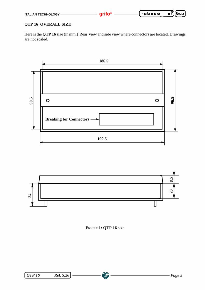
QTP 16 OVERALL SIZE
Here is the QTP 16 size (in mm.) Rear view and side view where connectors are located. Drawingsare not scaled.
FIGURE 1: QTP 16 SIZE
238.
5
34
192.5
96.5
186.5
90.5
Breaking for Connectors
grifo® ITALIAN TECHNOLOGY
Page 6 QTP 16 Rel. 5.20
ELECTRICAL FEATURES
Power supplt voltages: 5Vdc or 8÷24Vac
External loads power supply: 5Vdc (Option)
Power supply power: 5 W
RS 422-485 Termination Network: pull-up resistor on positive: 3.3 KΩpull-down resistor on negative: 3.3 KΩline termination resistor: 120 Ω
Optocoupler Power supply voltage: +12÷24 Vdc
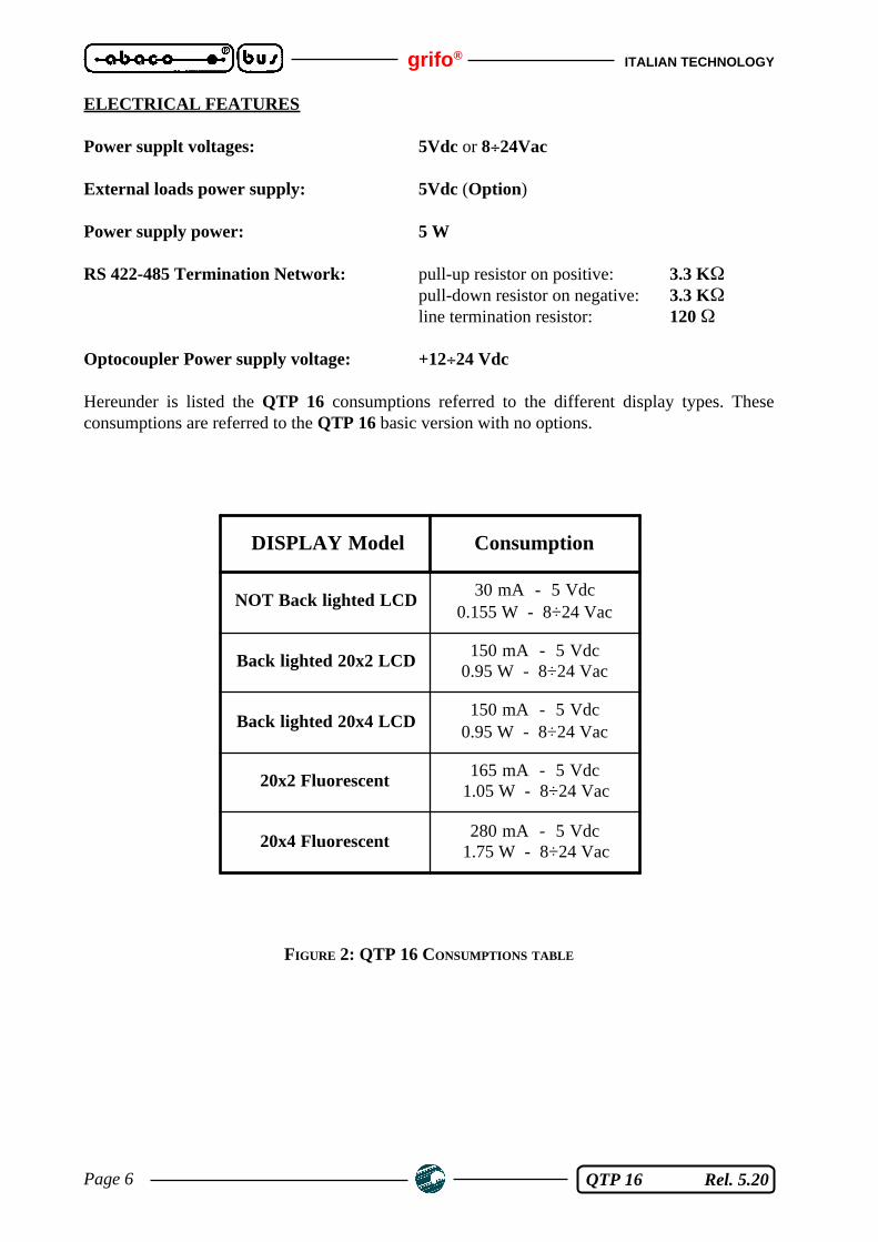
Hereunder is listed the QTP 16 consumptions referred to the different display types. Theseconsumptions are referred to the QTP 16 basic version with no options.
FIGURE 2: QTP 16 CONSUMPTIONS TABLE
DISPLAY Model Consumption
NOT Back lighted LCD30 mA - 5 Vdc
0.155 W - 8÷24 Vac
Back lighted 20x2 LCD150 mA - 5 Vdc
0.95 W - 8÷24 Vac
Back lighted 20x4 LCD150 mA - 5 Vdc
0.95 W - 8÷24 Vac
20x2 Fluorescent165 mA - 5 Vdc
1.05 W - 8÷24 Vac
20x4 Fluorescent280 mA - 5 Vdc
1.75 W - 8÷24 Vac
ITALIAN TECHNOLOGY grifo®
Page 7 QTP 16 Rel. 5.20
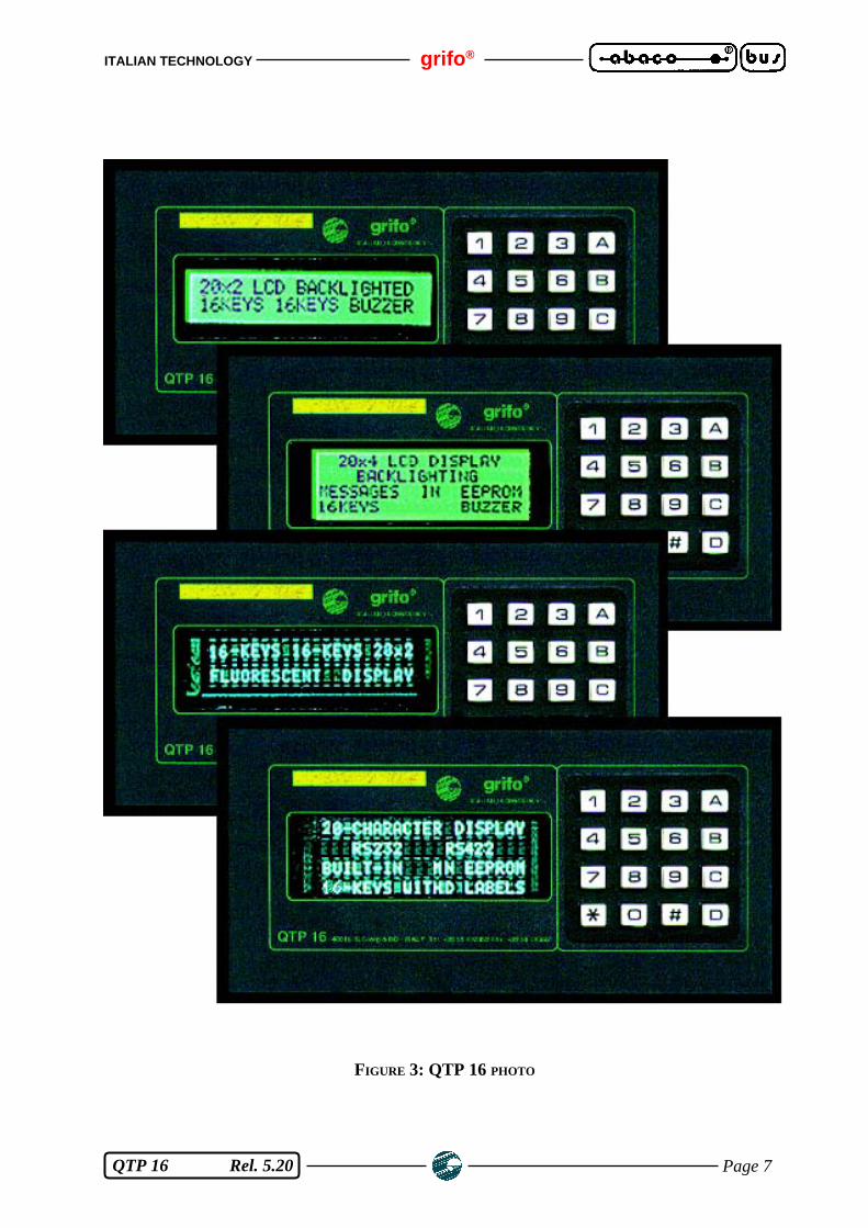
FIGURE 3: QTP 16 PHOTO

grifo® ITALIAN TECHNOLOGY
Page 8 QTP 16 Rel. 5.20
FIGURE 4: QTP 16 PANEL
QT
P 1
6
A B DC
2 5 08
1 4 *7
3 6 9 #
gri
fo®

ITALIAN TECHNOLOGY grifo®
Page 9 QTP 16 Rel. 5.20
TERMINAL INSTALLATION
This chapter illustrates all the operations which have to be done for the proper use of QTP 16terminal. QTP 16 is provided with 3 connectors (1 of which is optional) for getting all theconnections to the system. Here under please find the list of their Pin-Out and the meaning of theconnected signals.
CN5 - POWER SUPPLY CONNECTOR.
CN5 is a quick screw terminal connector having 2 or 4 pins. This connector must be used to supplyand/or get the requested and/or generated power supply voltage of the terminal.The standard QTP 16 version is supplied with a 2 pins connector for 8÷24Vac supply (please referto figure n. 6). All the other configurations are OPTIONS and must be requested in order phase.Here there is the rear view of the terminal where are shown the possible connector configurations.
4 PINS CONNECTOR FOR POWER SUPPLY
FIGURE 5: CN5 - 4 PINS CONNECTOR FOR POWER SUPPLY
Signals description:
8÷24 Vac = I - Lines for QTP 16 powering through A.C. voltage connected to theon-board switching section.
+5Vdc = O - Output line to supply an external load through the on-boardswitching power supply.
GND = Ground line for external load supply.
+ 5 VdcGND8÷24 Vac
grifo® ITALIAN TECHNOLOGY
Page 10 QTP 16 Rel. 5.20
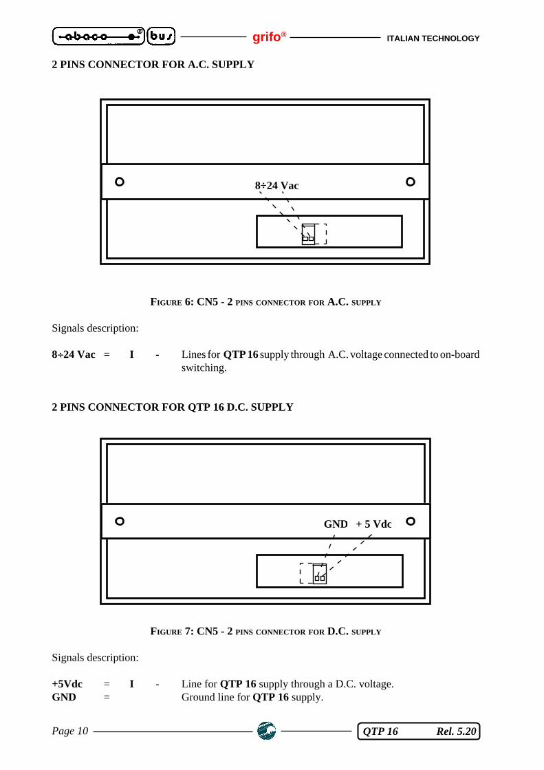
2 PINS CONNECTOR FOR A.C. SUPPLY
FIGURE 6: CN5 - 2 PINS CONNECTOR FOR A.C. SUPPLY
Signals description:
8÷24 Vac = I - Lines for QTP 16 supply through A.C. voltage connected to on-boardswitching.
2 PINS CONNECTOR FOR QTP 16 D.C. SUPPLY
FIGURE 7: CN5 - 2 PINS CONNECTOR FOR D.C. SUPPLY
Signals description:
+5Vdc = I - Line for QTP 16 supply through a D.C. voltage.GND = Ground line for QTP 16 supply.
8÷24 Vac
+ 5 VdcGND

ITALIAN TECHNOLOGY grifo®
Page 11 QTP 16 Rel. 5.20
CN6 - OPTOCOUPLED INPUTS CONNECTOR (OPTIONAL)
CN6 is a 5 pins quick screw terminal connector. On this connector the 4 NPN optocoupled input linesand the +Vopto signal to power the on-board OPTOCOUPLER components are available.
FIGURE 8: CN6 - OPTOCOUPLED INPUTS CONNECTOR
Signals description:
INn = I - NPN input connected to the optocoupled "n" line.+Vopto = I - Power supply for the Optocoupler (+12÷+24 Vdc).
FIGURE 9: OPTOCOUPLED INPUTS CONNECTION EXAMPLE
+Vopto IN3 IN2 IN1 IN0
5
4
1
+Vopto
IN3
IN0
5 P
in C
onne
ctor
CN
6 Q
TP
16
3
2
IN2
IN1
+ -
12÷24 Vdc

grifo® ITALIAN TECHNOLOGY
Page 12 QTP 16 Rel. 5.20
CN4 - CONNECTOR FOR SERIAL COMMUNICATION
CN4 is a 9 pins D female connector. On CN4 connector are available the buffered signals for RS 232,RS 422-485 or Current Loop serial communication. Only one of the described standards isconnected to CN4, but the same connector can be used for any of the listed electric protocols (CCITTnormative). Signals location has been carefully studied in order to reduce to the minimum level theinterferences and making easier the connection to the field.
RS 232 CONNECTION
FIGURE 10: CN4 - RS 232 PIN-OUT AND CONNECTION EXAMPLE
Signals description:
RxD = I - Receive Data.TxD = O - Transmit Data.GND = Ground line.
3
4
5
9
7
GND
TxD
1
2 RxD
6
8
2
3
5
RxD
TxD
GND GND
RxD
TxD
Mas
ter
Rem
ote
Syst
em
9 P
in C
onne
ctor
CN
4 Q
TP
16

ITALIAN TECHNOLOGY grifo®
Page 13 QTP 16 Rel. 5.20
RS 422 CONNECTION
FIGURE 11: CN4 - RS 422 PIN-OUT AND CONNECTION EXAMPLE
Signals description:
RX- = I - Receive Data Negative for 4 wires RS 422.RX+ = I - Receive Data Positive for 4 wires RS 422.TX- = O - Transmit Data Negative for 4 wires RS 422.TX+ = O - Transmit Data Positive for 4 wires RS 422.GND = Ground line.
3
4
5
9
7
GND
TX+
TX-
1RX-
2RX+
6
8
1
2
5
RX -
RX +
GND GND
TX +
TX -
Mas
ter
Rem
ote
Syst
em
9 P
in C
onne
ctor
CN
4 Q
TP
16
3
4
TX -
TX + RX +
RX -
grifo® ITALIAN TECHNOLOGY
Page 14 QTP 16 Rel. 5.20
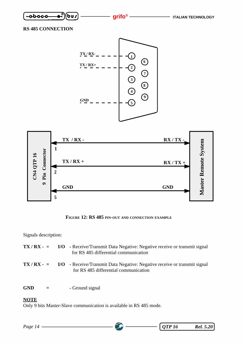
RS 485 CONNECTION
FIGURE 12: RS 485 PIN-OUT AND CONNECTION EXAMPLE
Signals description:
TX / RX - = I/O - Receive/Transmit Data Negative: Negative receive or transmit signal for RS 485 differential communication
TX / RX - = I/O - Receive/Transmit Data Negative: Negative receive or transmit signal for RS 485 differential communication
GND = - Ground signal
NOTEOnly 9 bits Master-Slave communication is available in RS 485 mode.
1
2
5
TX / RX -
TX / RX +
GND GND
RX / TX +
RX / TX -
Mas
ter
Rem
ote
Syst
em
9 P
in C
onne
ctor
CN
4 Q
TP
16
3
4
5
9
7
GND
1TX / RX-
2TX / RX+
6
8
ITALIAN TECHNOLOGY grifo®
Page 15 QTP 16 Rel. 5.20
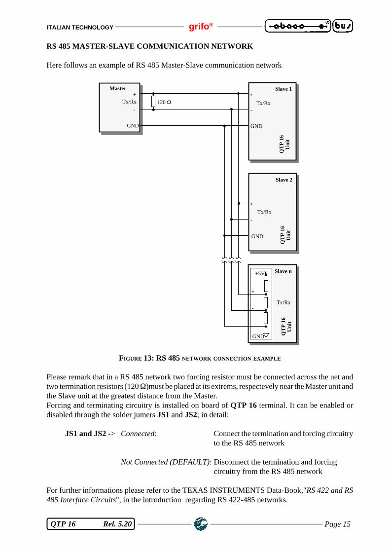
RS 485 MASTER-SLAVE COMMUNICATION NETWORK
Here follows an example of RS 485 Master-Slave communication network
FIGURE 13: RS 485 NETWORK CONNECTION EXAMPLE
Please remark that in a RS 485 network two forcing resistor must be connected across the net andtwo termination resistors (120 Ω)must be placed at its extrems, respectevely near the Master unit andthe Slave unit at the greatest distance from the Master.Forcing and terminating circuitry is installed on board of QTP 16 terminal. It can be enabled ordisabled through the solder jumers JS1 and JS2; in detail:
JS1 and JS2 -> Connected: Connect the termination and forcing circuitryto the RS 485 network
Not Connected (DEFAULT): Disconnect the termination and forcingcircuitry from the RS 485 network
For further informations please refer to the TEXAS INSTRUMENTS Data-Book,"RS 422 and RS485 Interface Circuits", in the introduction regarding RS 422-485 networks.
Tx/Rx +
-
GND
Master
120 Ω
QT
P 1
6U
nit
Tx/Rx
+
-
Slave n
GND
+5V
Tx/Rx
+
-
GND
Slave 2
QT
P 1
6U
nit
Tx/Rx
+
-
GND
Slave 1
QT
P 1
6 U
nit
grifo® ITALIAN TECHNOLOGY
Page 16 QTP 16 Rel. 5.20
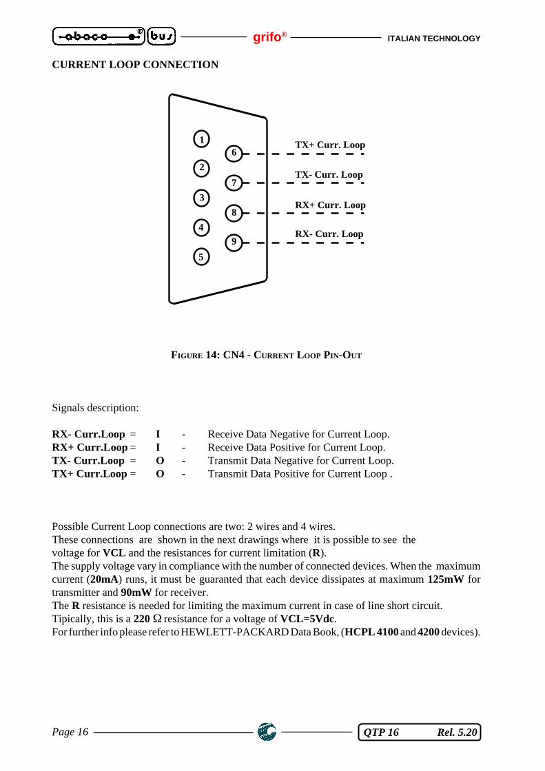
CURRENT LOOP CONNECTION
FIGURE 14: CN4 - CURRENT LOOP PIN-OUT
Signals description:
RX- Curr.Loop = I - Receive Data Negative for Current Loop.RX+ Curr.Loop = I - Receive Data Positive for Current Loop.TX- Curr.Loop = O - Transmit Data Negative for Current Loop.TX+ Curr.Loop = O - Transmit Data Positive for Current Loop .
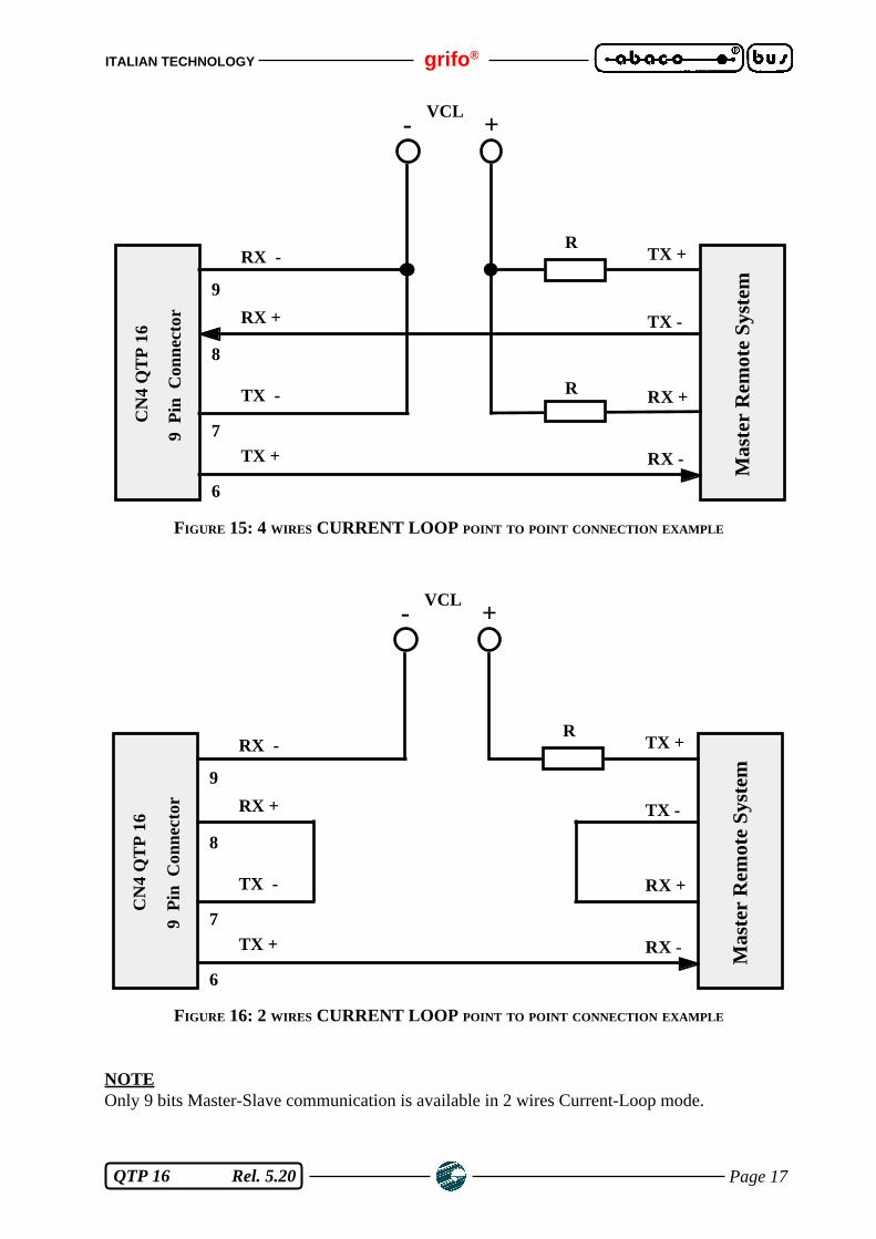
Possible Current Loop connections are two: 2 wires and 4 wires.These connections are shown in the next drawings where it is possible to see thevoltage for VCL and the resistances for current limitation (R).The supply voltage vary in compliance with the number of connected devices. When the maximumcurrent (20mA) runs, it must be guaranted that each device dissipates at maximum 125mW fortransmitter and 90mW for receiver.The R resistance is needed for limiting the maximum current in case of line short circuit.Tipically, this is a 220 Ω resistance for a voltage of VCL=5Vdc.For further info please refer to HEWLETT-PACKARD Data Book, (HCPL 4100 and 4200 devices).
3
4
5
9
7
RX- Curr. Loop
TX- Curr. Loop
1
2
6TX+ Curr. Loop
8RX+ Curr. Loop
ITALIAN TECHNOLOGY grifo®
Page 17 QTP 16 Rel. 5.20
FIGURE 15: 4 WIRES CURRENT LOOP POINT TO POINT CONNECTION EXAMPLE
FIGURE 16: 2 WIRES CURRENT LOOP POINT TO POINT CONNECTION EXAMPLE
NOTEOnly 9 bits Master-Slave communication is available in 2 wires Current-Loop mode.
9
8
RX -
RX + TX -
TX +
Mas
ter
Rem
ote
Syst
em
9 P
in C
onne
ctor
CN
4 Q
TP
16
7
6
TX -
TX + RX -
RX +
- +VCL
R
R
9
8
RX -
RX + TX -
TX +M
aste
r R
emot
e Sy
stem
9 P
in C
onne
ctor
CN
4 Q
TP
16
7
6
TX -
TX + RX -
RX +
- +VCL
R

grifo® ITALIAN TECHNOLOGY
Page 18 QTP 16 Rel. 5.20
SOFTWARE DESCRIPTION
As already said QTP 16 terminal is a complete video terminal and for this reason any thing receivedthrough serial line, if it is not a command, is shown on the display and codes of any key pressed onthe keyboard is transmitted to the control master unit. On board of this terminal panel is alsoimplemented a local set-up program which allows to set the communication protocol by using theQTP’s keyboard and display. This manual contains, in addition to the description of the differentfunctions, a complete list of the comand sequences and the recognized combination to be used tobenefit of the main features of QTP 16. For each code or codes sequence, there is a double descriptioni.e: the mnemonic one through the ASCII characters and the numerical one under decimal andhexdecimal form. The said commands respect the ADDS View Point standard so all the sequencesbegin with ESC character corresponding to the 27 decimal code (1B Hex).
LOCAL SETUP
To enter in Setup mode the user must press the "1" and "D" keys at the power-on time.When entered in Setup mode on the display appears the "-Setup-" string and the terminal awaits untilthe user presses one of the following keys:
Key "1" : Allows to select the parameter to set, switching amongst the following menus:
"COMMUNICATION" (communication mode), "BAUD RATE" (Baud Rate),"KEYCLICK" (Key-Click function), "NAME" (first figure of NAME),"NAME" (second figure of NAME) and "SAVE and EXIT" (exit from Setup).
Key "2" : Allows to set the parameter selected by the key "1", in detail:
COMMUNICATION: Normal or Master-Slave.BAUD RATE: 38400, 19200, 9600, 4800, 2400 or 1200 Baud.STOP BIT: 1 or 2 when communication is Normal.
1 when communication is Master-Slave.KEYCLIK: ON or OFF.NAME: Changes the figure indicated by ">" and "<" in the range
0÷F Hex.SAVE and EXIT: Exits from setup and configures QTP 16 with the
parameters set now.
Please remark that the code input under the menu "NAME" will be the code to be used to identifythe QTP 16 during the Master-Slave communication, as shown in the paragraph dedicated to thissubject.

ITALIAN TECHNOLOGY grifo®
Page 19 QTP 16 Rel. 5.20
KEYBOARD ACQUISITION
When QTP 16 recognizes the key pressure, it transmits the pertinent code on serial line.The AutoRepeat function of the pressed key is also implemented so when QTP 16 recognizes thepressure on a specific key for a period of time over 0.5 sec. it will start the serial transmission ofits code for about 0.1 sec. and it lasts until that specific key is released.
DEFAULT KEY CODES
Here follows a table reporting the codes sent to the serial line when a key is pressed; the codes areexpressed in decimal, hexadecimal and ASCII.
FIGURE 17: DEFAULT KEY CODES
KEY CODE HEX CODE MNEMONIC
1 (number 0) 49 31 1
2 (number 1) 50 32 2
3 (number 2) 51 33 3
A (number 3) 65 41 A
4 (number 4) 52 34 4
5 (number 5) 53 35 5
6 (number 6) 54 36 6
B (number 7) 66 42 B
7 (number 8) 55 37 7
8 (number 9) 56 38 8
9 (number 10) 57 39 9
C (number 11) 67 43 C
* (number 12) 27 1B ESC
0 (number 13) 48 30 0
# (number 14) 13 0D CR
D (number 15) 68 44 D

grifo® ITALIAN TECHNOLOGY
Page 20 QTP 16 Rel. 5.20
CHARACTER VISUALIZATION ON THE DISPLAY
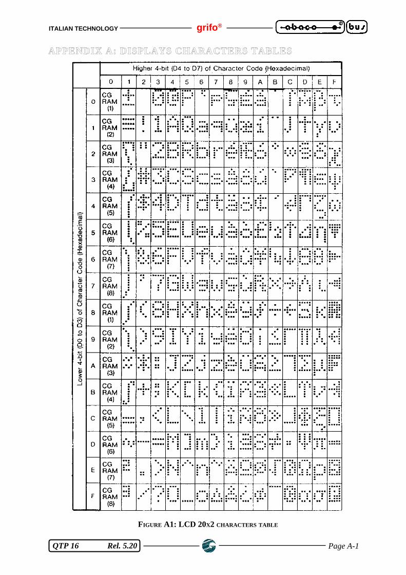
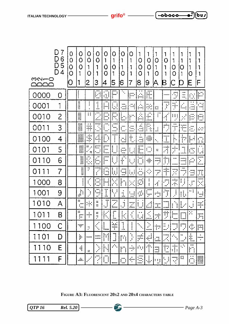
QTP 16 shows on the display all the characters having a code included in the range 32÷255 (20÷FFHex); if it is sent a code not included in this range and this latter is not a command, the code is ignored.The characters in the range: 32÷127 (20÷7F Hex) correspond to those ones of the standard ASCIItable, while characters associated to 128÷255 (80÷FF Hex) codes, vary depending on the type of thedisplay installed. This is the reason why the User sholud refer to appendix "A" tables.The character is visualized in the at the cursor position and this latter will go the the next position;if it is placed in the last position of the last row, it will be moved to Home position.
COMMANDS FOR CURSOR POSITIONING
Here follows the list of the cursor positioning commands.
CURSOR LEFT
Code: 21 (15Hex)Mnemonic: NACK
The cursor is shifted of one position to the left without modifying the display contents. If the cursoris in Home position, it will be placed in the last position of the last row of the display.
CURSOR RIGHT
Code: 06Mnemonic: ACK
The cursor is shifted of one position to the right.If the cursor is placed in the last position of the last row, il will be moved to the Home position.
CURSOR DOWN
Code: 10 (0A Hex)Mnemonic: LF
The cursor will be moved to the line below but it will remain in the same column.If the cursor is in the last display line, it will be moved to the first display line.
CURSOR UP
Code: 26 (1A Hex)Mnemonic: SUB
The cursor will be moved to the line above but it will remain in the same column. If the cursor is inthe first display line, it will be moved to the last display line.

ITALIAN TECHNOLOGY grifo®
Page 21 QTP 16 Rel. 5.20
HOME
Code: 01Mnemonic: SOH
The cursor is moved to Home position i.e first line, first column of the display.
CARRIAGE RETURN
Code: 13 (0D Hex)Mnemonic: CR
The cursor is moved to the beginning of the line where it finds.
CARRIAGE RETURN+LINE FEED
Code: 29 (1D Hex)Mnemonic: GS
The cursor is moved to the beginning of line above the one where it finds.If the cursor is at the last display line, it will be moved to the beginning of the first line i.e Homeposition.
CURSOR ABSOLUTE POSITIONING WITH 20H OFFEST
Code: 27 89 r c (1B 59 r c Hex)Mnemonic: ESC Y ASCII(r) ASCII(c)
The cursor is moved to the absolute position indicated by "r" and "c".These codes are line and column values of the position plus 32 (20 Hex). If, for example, the User wants to place the cursor at Home position (line 0, column 0), the followingbyte sequence must be sent to the QTP 16: 27 89 32 32.If line and/or column values are not compatible to the installed display, the command is ignored.

grifo® ITALIAN TECHNOLOGY
Page 22 QTP 16 Rel. 5.20
COMMANDS FOR CHARACTERS ERASURE
In the following paragraphs are described all the commands that deletes one or more characters fromthe display.
BACKSPACE
Code: 08 (08 Hex)Mnemonic: BS
This command moves the cursor one character position to the left and it erase the contents of thereached cell. If the cursor is in home position, it will be erased the last character of the last row ofthe display.
CLEAR PAGE
Code: 12 (0C Hex)Mnemonic: FF
This command clears all data on the display and it moves the cursor to home position.
CLEAR LINE
Code: 25 (19 Hex)Mnemonic: EM
This command erases all characters displayed on the current line and it moves the cursor to the firstcolumn of the said line.
CLEAR END OF LINE
Code: 27 75 (1B 4B Hex)Mnemonic: ESC K
This command erases all characters displayed from the current cursor position to the end of lineinclusive. The cursor doesn't move and at the end of the command execution it mantains the previouscurrent position. If, for example, the cursor is at the beginning of a display line, the complete line willbe erased.
ITALIAN TECHNOLOGY grifo®
Page 23 QTP 16 Rel. 5.20
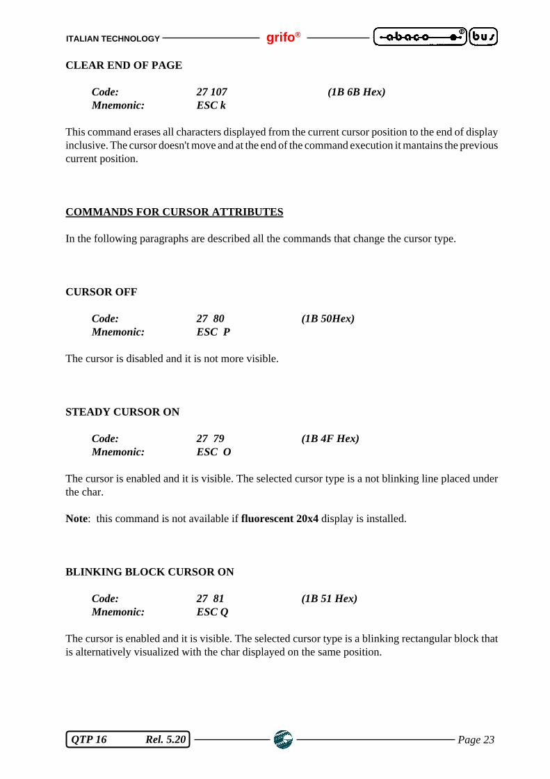
CLEAR END OF PAGE
Code: 27 107 (1B 6B Hex)Mnemonic: ESC k
This command erases all characters displayed from the current cursor position to the end of displayinclusive. The cursor doesn't move and at the end of the command execution it mantains the previouscurrent position.
COMMANDS FOR CURSOR ATTRIBUTES
In the following paragraphs are described all the commands that change the cursor type.
CURSOR OFF
Code: 27 80 (1B 50Hex)Mnemonic: ESC P
The cursor is disabled and it is not more visible.
STEADY CURSOR ON
Code: 27 79 (1B 4F Hex)Mnemonic: ESC O
The cursor is enabled and it is visible. The selected cursor type is a not blinking line placed underthe char.
Note: this command is not available if fluorescent 20x4 display is installed.
BLINKING BLOCK CURSOR ON
Code: 27 81 (1B 51 Hex)Mnemonic: ESC Q
The cursor is enabled and it is visible. The selected cursor type is a blinking rectangular block thatis alternatively visualized with the char displayed on the same position.

grifo® ITALIAN TECHNOLOGY
Page 24 QTP 16 Rel. 5.20
COMMANDS FOR EEPROM
In the following paragraphs are described all the commands that manage the data saved on QTP 16on board EEPROM.
REQUEST FOR EEPROM WRITING POSSIBILITY
Code: 27 51 (1B 33 Hex)Mnemonic: ESC 3
This command checks if the QTP 16 is ready for writing data on its on board EEPROM. Thiscommand must be executed any time there are messages to be memorized or when some EEPROMcommands must be sent.When QTP 16 receives this command, it answers with the following codes:
6 - 06 Hex (ACK) QTP 16 READY21 - 15 Hex (NACK) QTP 16 NOT READY
If the QTP 16 sends back the NACK code, it is not yet possible to memorize a new data on EEPROM.
WRITING OF LIFE BYTE
Code: 27 33 78 byte (1B 21 4E byte Hex)Mnemonic: ESC ! N ASCII (byte)
This command sets the card "Life Byte" with the value indicated in the byte parameter that can beincluded in 0÷255 range.This byte has a reserved allocation on the on board EEPROM that, once it is set with the desideredvalue, it allows for example, to verify that QTP 16 runs correctly, or if there are some communicationproblems on the serial line.
NOTEThis command writes data on the on board EEPROM, so before executing it is better to check theEEPROM writing possibility through the proper command; in fact if it is not ready the command isignored.
READING OF LIFE BYTE
Code: 27 33 110 (1B 21 6E Hex)Mnemonic: ESC ! n
The QTP 16 sends back on the serial line the value of its "Life Byte".This command can be useful if you have to verify the presence or the correct running of the card.

ITALIAN TECHNOLOGY grifo®
Page 25 QTP 16 Rel. 5.20
COMMANDS FOR KEYBOARD
In the following paragraphs are described all the commands that manage the QTP 16 externalkeyboard.
KEY RECONFIGURATION
Code: 27 55 key no. code (1B 37 key no. code Hex)Mnemonic: ESC 7 ASCII(key no.) ASCII(code)
When the selected key is reconfigured, each time it is pressed, the card will send the new specifiedcode on serial line. The value of key no. to be reconfigured must be in the range 0÷15 (0÷F Hex) andit will replace the codes described in figure 17.
The code value can vary in the range 0÷254 (0÷FE Hex) as the 255 value (FF Hex) indicates thatthe key is disabled and when it will be pressed the QTP 16 will not send any code.
NOTEThis command writes data on the on board EEPROM, so before executing it is better to check theEEPROM writing possibility through the proper command; in fact if it is not ready the command isignored. Furthermore if the key no. is not valid, the entire command is ignored.
KEYCLICK ON WITHOUT MEMORIZATION
Code: 27 53 (1B 35 Hex)Mnemonic: ESC 5
This command enables KeyClick function, so there is an audible feedback when a key is pressed.This setting is not stored on the on board EEPROM so if the card is turned off and on, it returns tothe previous condition.
KEYCLICK OFF WITHOUT MEMORIZATION
Code: 27 54 (1B 36 Hex)Mnemonic: ESC 6
This command disables KeyClick function, so there is not audible feedback when a key is pressed.This setting is not stored on the on board EEPROM so if the card is turned off and on, it returns tothe previous condition.

grifo® ITALIAN TECHNOLOGY
Page 26 QTP 16 Rel. 5.20
KEYCLICK ON WITH MEMORIZATION
Code: 27 33 53 (1B 21 35 Hex)Mnemonic: ESC ! 5
This command enables KeyClick function, so there is an audible feedback when a key is pressed.This setting is stored on the on board EEPROM so if the card is turned off and on, it keeps the currentcondition.
NOTEThis command writes data on the on board EEPROM, so before executing it is better to check theEEPROM writing possibility through the proper command; in fact if it is not ready the command isignored.
KEYCLICK OFF WITH MEMORIZATION
Code: 27 33 54 (1B 21 36 Hex)Mnemonic: ESC ! 6
This command disables KeyClick function, so there is not audible feedback when a key is pressed.This setting is stored on the on board EEPROM so if the card is turned off and on, it keeps the currentcondition.
NOTEThis command writes data on the on board EEPROM, so before executing it is better to check theEEPROM writing possibility through the proper command; in fact if it is not ready the command isignored.

ITALIAN TECHNOLOGY grifo®
Page 27 QTP 16 Rel. 5.20
COMMANDS FOR GENERAL FUNCTIONS
In the following paragraphs are described all the general purspose commands that manage some ofthe QTP 16 functions.
BEEP
Code: 07 (07 Hex)Menomonic: BEL
This command enables the buzzer for 1/10 of second.
READING OF VERSION NUMBER
Code: 27 86 (1B 56 Hex)Mnemonic: ESC V
When QTP 16 receives this command, it answers with a string of 3 chars containing the version, inthe format x.x, of the firmware that is saved on, and executed by, its CPU. For example with a 1.2firmware version the following characters will be transmitted: 49 46 50 (31 2E 32 Hex).
grifo® ITALIAN TECHNOLOGY
Page 28 QTP 16 Rel. 5.20
COMMANDS FOR MESSAGES MANAGEMENT
In the following paragraphs are described all the commands that manage messages on QTP 16.
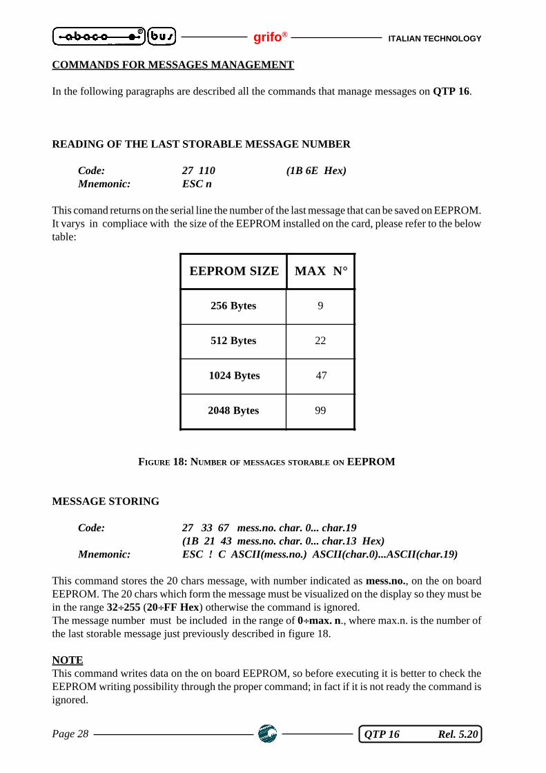
READING OF THE LAST STORABLE MESSAGE NUMBER
Code: 27 110 (1B 6E Hex)Mnemonic: ESC n
This comand returns on the serial line the number of the last message that can be saved on EEPROM.It varys in compliace with the size of the EEPROM installed on the card, please refer to the belowtable:
FIGURE 18: NUMBER OF MESSAGES STORABLE ON EEPROM
MESSAGE STORING
Code: 27 33 67 mess.no. char. 0... char.19(1B 21 43 mess.no. char. 0... char.13 Hex)
Mnemonic: ESC ! C ASCII(mess.no.) ASCII(char.0)...ASCII(char.19)
This command stores the 20 chars message, with number indicated as mess.no., on the on boardEEPROM. The 20 chars which form the message must be visualized on the display so they must bein the range 32÷255 (20÷FF Hex) otherwise the command is ignored.The message number must be included in the range of 0÷max. n., where max.n. is the number ofthe last storable message just previously described in figure 18.
NOTEThis command writes data on the on board EEPROM, so before executing it is better to check theEEPROM writing possibility through the proper command; in fact if it is not ready the command isignored.
EEPROM SIZE MAX N°
256 Bytes 9
512 Bytes 22
1024 Bytes 47
2048 Bytes 99
ITALIAN TECHNOLOGY grifo®
Page 29 QTP 16 Rel. 5.20
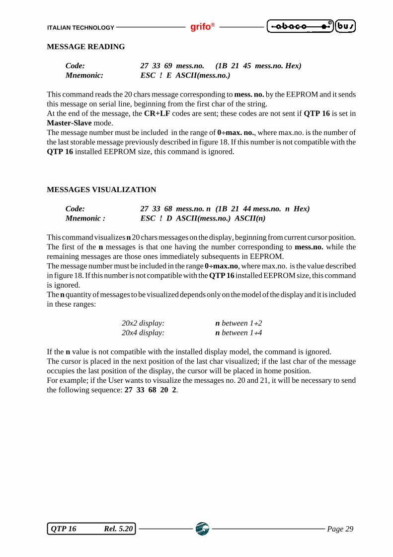
MESSAGE READING
Code: 27 33 69 mess.no. (1B 21 45 mess.no. Hex)Mnemonic: ESC ! E ASCII(mess.no.)
This command reads the 20 chars message corresponding to mess. no. by the EEPROM and it sendsthis message on serial line, beginning from the first char of the string.At the end of the message, the CR+LF codes are sent; these codes are not sent if QTP 16 is set inMaster-Slave mode.The message number must be included in the range of 0÷max. no., where max.no. is the number ofthe last storable message previously described in figure 18. If this number is not compatible with theQTP 16 installed EEPROM size, this command is ignored.
MESSAGES VISUALIZATION
Code: 27 33 68 mess.no. n (1B 21 44 mess.no. n Hex)Mnemonic : ESC ! D ASCII(mess.no.) ASCII(n)
This command visualizes n 20 chars messages on the display, beginning from current cursor position.The first of the n messages is that one having the number corresponding to mess.no. while theremaining messages are those ones immediately subsequents in EEPROM.The message number must be included in the range 0÷max.no, where max.no. is the value describedin figure 18. If this number is not compatible with the QTP 16 installed EEPROM size, this commandis ignored.The n quantity of messages to be visualized depends only on the model of the display and it is includedin these ranges:
20x2 display: n between 1÷220x4 display: n between 1÷4
If the n value is not compatible with the installed display model, the command is ignored.The cursor is placed in the next position of the last char visualized; if the last char of the messageoccupies the last position of the display, the cursor will be placed in home position.For example; if the User wants to visualize the messages no. 20 and 21, it will be necessary to sendthe following sequence: 27 33 68 20 2.

grifo® ITALIAN TECHNOLOGY
Page 30 QTP 16 Rel. 5.20
SCROLLING MESSAGE VISUALIZATION
Code: 27 33 83 mess.no. chars (1B 21 45 mess.no. chars Hex)Mnemonic: ESC ! E ASCII(mess.no.) ASCII(chars)
This command visualizes, on the first row of the display, a scrolling message chars charactes long;in fact the characters that form the message are shifted from the right to the left, making possible toshow on an unique row of the display (the first row), an amount of informations greater than the onenormally available.The message, which is chars characters long, begins from the first character of the message whosenumber is mess.no. and is composed by the characters that make the mess.no. message and thefollowing ones (making the following messages stored on the EEPROM).The message number must be included in the range of 0÷max. no., where max.no. is the number ofthe last storable message previously described in figure 18. If this number is not compatible with theQTP 16 installed EEPROM size, this command is ignored.The value chars may have these meanings:
0 Stops the current scrolling (value of mess.no. is irrilevant)
20÷200 Starts to scroll the indicated number of characters
If chars has a vaule out of these ranges or it extends the scrolling messages beyond the limit of theEEPROM storage space, the command is ignored.
The message will scroll in the first row of the display, without changing position and attributes ofthe cursor.
This command is ignored if the optocoupled inputs-driven messages management mode is enabled.
If, for example, the User wants to show a scrolling message 23 characters long, made by message5 (20 characters) and the first 3 characters of message 6,it will be necessary to send the followingsequence: 27 33 83 5 23.
NOTEScrolling a message involves a continuous display updating; this operation slows the interpretationof commands coming from the serial port.So if a great amount of informations must be sent to QTP 16 and a message is scrolling on the display,it is suggestable to wait for some msec between the transmission of a 20÷30 bytes data block and thenext one, to assure that the terminal has had the time to interpretate correctly the transmitted data.

ITALIAN TECHNOLOGY grifo®
Page 31 QTP 16 Rel. 5.20
COMMANDS FOR OPTOCOUPLED INPUTS MANAGEMENT
Here follow the commands that manage the QTP 16 four optocoupled inputs.
OPTOCOUPLED INPUTS CONFIGURATION
Code: 27 33 73 byte (1B 21 49 byte Hex)Mnemonic: ESC ! I ASCII(byte)
The 4 optocoupled inputs configuration byte is stored on EEPROM with the following meaning:
Bit 0 --> 0 The optocoupled inputs are configured as GENERAL PURPOSE INPUTS1 The optocoupled inputs are configured for MESSAGE SELECTION
Bit 1÷7 --> 1 Not used (must be to "1" logic state)
Enabling or disabling the optocoupled inputs for message selection involves the stop of an eventualscrolling message.
For example; if the User wants to configure the optocoupled inputs for message selection, it will benecessary to send the following sequence 27 33 73 254 to the card.While, if the User wants to disable such feature, it will be necessary to send the following sequence27 33 73 255 to the card.
NOTEThis command needs a data writing in on-board EEPROM so before executing it be sure that the cardis ready for the new writing on that device, otherwise the command will be ignored. Please rememberthat the settings stored in EEPROM are maintained also after the power-off.
OPTOCOUPLED INPUTS-DRIVEN MESSAGES MANAGEMENT MODE
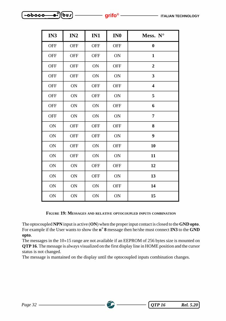
Through this working modality it is possible to show on the display of QTP 16 up to 16 messagestwenty characters long, simply by changing the status of the optocouped input lines. In fact the first16 messages stored in EEPROM are matched to the combinations obtainable with the possible valuesof optocoupled inputs.
Whenever the status of any of the inputs is changed, the matching message is shown on the first rowon the display. The message will remain on the display until the next change in the optocoupled inputsstatus occours.
The following table shows the matching between message number and optocoupled input.
grifo® ITALIAN TECHNOLOGY
Page 32 QTP 16 Rel. 5.20
FIGURE 19: MESSAGES AND RELATIVE OPTOCOUPLED INPUTS COMBINATION
The optocoupled NPN input is active (ON) when the proper input contact is closed to the GND opto.For example if the User wants to show the n° 8 message then he/she must connect IN3 to the GNDopto.The messages in the 10÷15 range are not available if an EEPROM of 256 bytes size is mounted onQTP 16. The message is always visualized on the first display line in HOME position and the cursorstatus is not changed.The message is mantained on the display until the optocoupled inputs combination changes.
IN3 IN2 IN1 IN0 Mess. N°
OFF OFF OFF OFF 0
OFF OFF OFF ON 1
OFF OFF ON OFF 2
OFF OFF ON ON 3
OFF ON OFF OFF 4
OFF ON OFF ON 5
OFF ON ON OFF 6
OFF ON ON ON 7
ON OFF OFF OFF 8
ON OFF OFF ON 9
ON OFF ON OFF 10
ON OFF ON ON 11
ON ON OFF OFF 12
ON ON OFF ON 13
ON ON ON OFF 14
ON ON ON ON 15

ITALIAN TECHNOLOGY grifo®
Page 33 QTP 16 Rel. 5.20
OPTOCOUPLED INPUTS READING
Code: 27 73 byte (1B 49 byte Hex)Mnemonic: ESC I ASCII(byte)
A 1 byte value containing the optocoupled inputs status is sent to the serial line:
Bit 7 --> 0Bit 6 --> 0Bit 5 --> 0Bit 4 --> 0Bit 3 --> IN3Bit 2 --> IN2Bit 1 --> IN1Bit 0 --> IN0
where:
Bit n = "1" logic status --> Input ON --> Input contact CLOSEDBit n = "0" logic status --> Input OFF --> Input contact OPEN
Remember that an optocoupled NPN input is active (ON) when the proper input contact is closedto the GND opto.
grifo® ITALIAN TECHNOLOGY
Page 34 QTP 16 Rel. 5.20
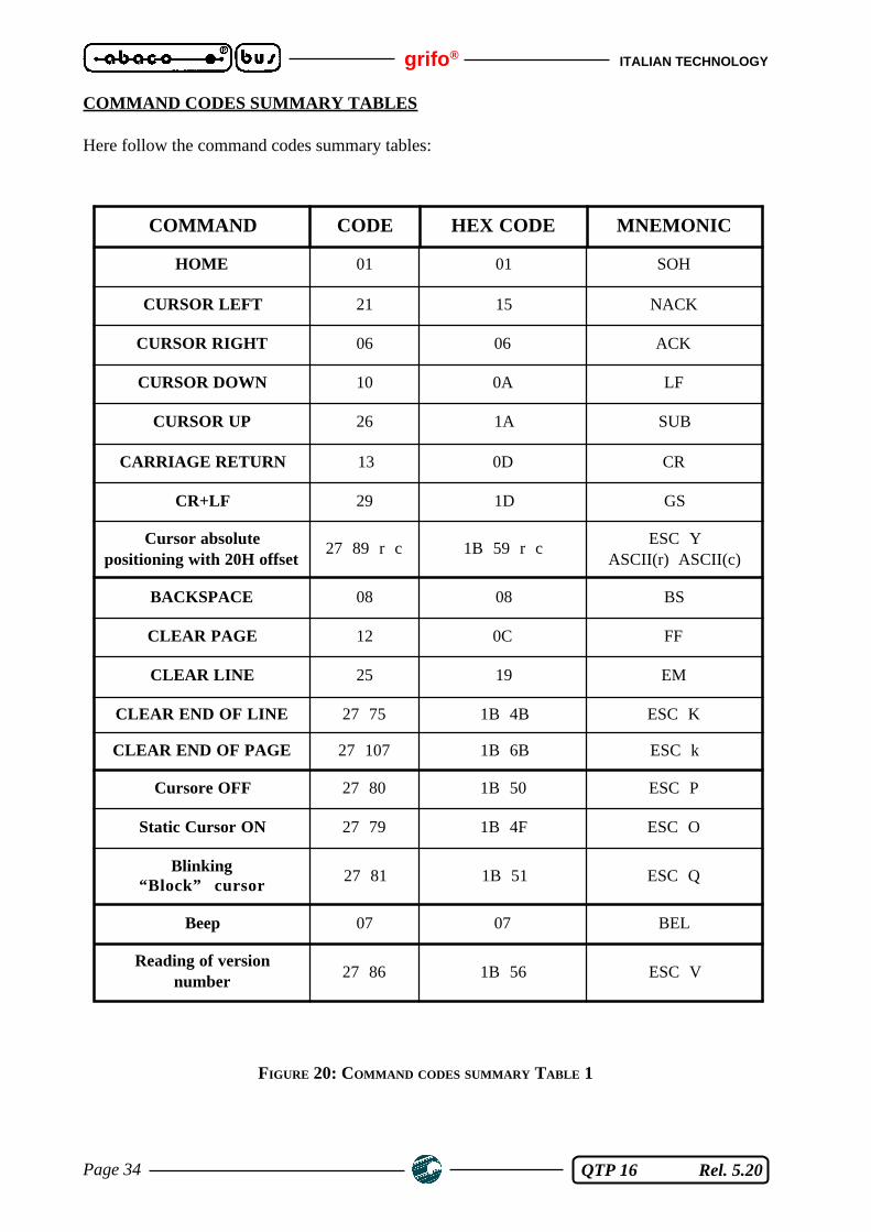
COMMAND CODES SUMMARY TABLES
Here follow the command codes summary tables:
FIGURE 20: COMMAND CODES SUMMARY TABLE 1
COMMAND CODE HEX CODE MNEMONIC
HOME 01 01 SOH
CURSOR LEFT 21 15 NACK
CURSOR RIGHT 06 06 ACK
CURSOR DOWN 10 0A LF
CURSOR UP 26 1A SUB
CARRIAGE RETURN 13 0D CR
CR+LF 29 1D GS
Cursor absolutepositioning with 20H offset
27 89 r c 1B 59 r cESC Y
ASCII(r) ASCII(c)
BACKSPACE 08 08 BS
CLEAR PAGE 12 0C FF
CLEAR LINE 25 19 EM
CLEAR END OF LINE 27 75 1B 4B ESC K
CLEAR END OF PAGE 27 107 1B 6B ESC k
Cursore OFF 27 80 1B 50 ESC P
Static Cursor ON 27 79 1B 4F ESC O
Blinking“Block” cursor
27 81 1B 51 ESC Q
Beep 07 07 BEL
Reading of versionnumber
27 86 1B 56 ESC V

ITALIAN TECHNOLOGY grifo®
Page 35 QTP 16 Rel. 5.20
FIGURE 21: COMMAND CODES SUMMARY TABLE 2
COMMAND CODE HEX CODE MNEMONIC
Request forEEPROM writing
27 51 1B 33 ESC 3
Writing of "life" byte27 33
78 key1B 21 4E key
ESC ! NASCII(key)
Reading of "life" byte 27 33 110 1B 21 6E ESC ! n
Characters show 32÷255 20÷FF “space”÷ASCII(255)
Key reconfiguration27 55
key no. code1B 37
key no. codeESC 7
ASCII(key no.) ASCII(code)
KeyClick ON withoutmemorization
27 53 1B 35 ESC 5
KeyClick OFF withoutmemorization
27 54 1B 36 ESC 6
KeyClick ON withmemorization
27 33 53 1B 21 35 ESC ! 5
KeyClick OFF withmemorization
27 33 54 1B 21 36 ESC ! 6
Number reading of thelast stored message
27 110 1B 6E ESC n
Storing message
27 33 67mess.no.
char.0…char.19
1B 21 43 mess.no.char.0…char.13
ESC ! CASCII(mess.no.)
ASCII(char.0)…ASCII(char.19)
Message reading27 33 69mess.no.
1B 21 45 mess.no. ESC ! E ASCII(mess.no.)
Messages visualization27 33 68mess.no. 1
1B 21 44mess.no. 1
ESC ! DASCII(mess.no.) SOH
SCROLLINGMESSAGE
VISUALIZATION
27 33 83mess.no.
chars
1B 21 53 mess.no. chars
ESC ! SASCII(mess.no.)
ASCII(chars)
Optocoupled inputsconfiguration
27 33 73byte
1B 21 49 byte ESC ! I ASCII(byte)
Optocoupled inputsreading
27 73 1B 49 ESC I
grifo® ITALIAN TECHNOLOGY
Page 36 QTP 16 Rel. 5.20
MASTER-SLAVE COMMUNICATION MODE
The Master-Slave mode uses the 9 bits communication technique. In addition to the 8 data bit alsoa 9th bit is managed as it is needed for recognizing between a call coming from the "Master" to anyof the "Slave" structures and a simple info transmission between Master and the selected device.When 9th bit is placed at 1, the data byte has to contain the name, or identifying code, of the devicetowards it needs to communicate, while by placing this particular bit at 0 position, it is possible totake out or supply with info at this device.
As far as communications to QTP 16, the identifying code must be that one set by the local Set upprogramm of the terminal itself.When this byte is sent (with 9th bit set to 1) the QTP 16 recognizes itself and it waits the stringcontaining chars., data or commands; this string must be at most 25 bytes wide. In this string theremust only be a comand that involves the return of an information sent via serial line on QTP 16 part;if there is an higher number, the remaining commands of these type are ignored.Between the transmission of a char. and the next one there must be an interval of time shorter thanthe Time-Out, as elapsed this delay, the QTP 16 will consider the data string ended and it will beginthe answering phase.
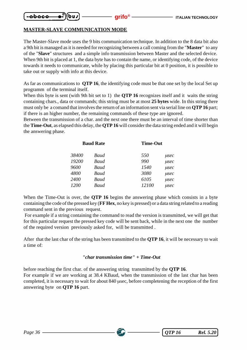
Baud Rate Time-Out
38400 Baud 550 µsec19200 Baud 990 µsec9600 Baud 1540 µsec4800 Baud 3080 µsec2400 Baud 6105 µsec1200 Baud 12100 µsec
When the Time-Out is over, the QTP 16 begins the answering phase which consists in a bytecontaining the code of the pressed key (FF Hex, no key is pressed) or a data string related to a readingcommand sent in the previous request. For example if a string containing the command to read the version is transmitted, we will get thatfor this particular request the pressed key code will be sent back, while in the next one the numberof the required version previously asked for, will be transmitted .
After that the last char of the string has been transmitted to the QTP 16, it will be necessary to waita time of:
"char transmission time" + Time-Out
before reaching the first char. of the answering string transmitted by the QTP 16.For example if we are working at 38.4 KBaud, when the transmission of the last char has beencompleted, it is necessary to wait for about 840 µsec, before completening the reception of the firstanswering byte on QTP 16 part.

ITALIAN TECHNOLOGY grifo®
Page 37 QTP 16 Rel. 5.20
NOTES
1) Between a call and the next one, it is necessary to wait for a time that is related to the numberof commands sent and type of operations these latter ones involve.
2) If the scrolling messages function or the optocoupled inputs-driven messages managementmode is enabled, the time between two calls must be the one of point 1) plus 12 msec.
3) If the Master unit cannot communicate using 9 bits, it is possible to simulate this communicationmode by means of the parity but and programming its value opportunally before anytranmission according to this scheme:
If the byte to transmit has EVEN number of "1" bitsIf 9th bit must be 1 -> Set parity to ODDIf 9th bit must be 0 -> Set parity to EVEN
If the byte to transmit has ODD number of "1" bitsIf 9th bit must be 1 -> Set parity to EVENIf 9th bit must be 0 -> Set parity to ODD

grifo® ITALIAN TECHNOLOGY
Page 38 QTP 16 Rel. 5.20
ITALIAN TECHNOLOGY grifo®
QTP 16 Rel. 5.20 Page A-1
APPENDIX A: DISPLAYS CHARACTERS TABLES
FIGURE A1: LCD 20X2 CHARACTERS TABLE

grifo® ITALIAN TECHNOLOGY
Page A-2 QTP 16 Rel. 5.20
FIGURE A2: LCD 20X4 CHARACTERS TABLE
ITALIAN TECHNOLOGY grifo®
QTP 16 Rel. 5.20 Page A-3
FIGURE A3: FLUORESCENT 20X2 AND 20X4 CHARACTERS TABLE

grifo® ITALIAN TECHNOLOGY
Page A-4 QTP 16 Rel. 5.20

ITALIAN TECHNOLOGY grifo®
QTP 16 Rel. 5.20 Page B-1
APPENDIX B: INSTALLATION NOTES
LABEL INSERTION
The QTP 16 has a personalization label window where the user can put its own logo, identificationcode or anything else. By using a 80 g/m2 paper sheet to create this label. In the following picture isshown the personalization label size express in mm.Note that in this picture the "grey part" is that one that can be read in the QTP 16 personalizationwindow.
FIGURE B1: PERSONALIZATION LABEL SIZE
Note for inserting the label:
A) Unscrew the 2 black screws from the front panel (if any).
B) Take the panel out separating the back carter - frame group from the printed circuit - keyboardgroup. The user must press connectors on the QTP 16 to facilitate this operation.
C) Now the keyboard is ready to accept the personalization label (see figure B2).
D) Remount the panel following the previous instructions but on the back-way.
FIGURE B2: PERSONALIZATION LABEL INSERTION
50
20
Personalization label
Insertion window
Insertion slot
QTP 16 front panel(rear view)

grifo® ITALIAN TECHNOLOGY
Page B-2 QTP 16 Rel. 5.20
HOW TO FIX THE FRONT PANEL TO THE CARTER
The QTP 16 is supplied with the front panel (printed circuit - keyboard) fitted to the rear carter.If the User wants to improve the mechanical fixing between the panel and the carter, to avoid anaccidental panel out-of-frame, then he/she must follow these instructions point by point:
1) Take the panel out separating the rear carter + frame group from the printed circuit + keyboardgroup. The User should press connectors on the QTP 16 to facilitate this operation.
2) Unscrew the 2 central screws to separate the frame from the rear carter.
3) On the front panel, in corrispondance to those 2 central screws, there are 2 countersink holeswhich are visible only in the rear view. To get these two holes accesible, the user needs to holethe polycarbonate panel covering.
4) Remount the panel by using the two screws of point "2". They will be screwed on the frontpanel instead of the frontal frame.
AUXILIARY FIXING SCREW

ITALIAN TECHNOLOGY grifo®
QTP 16 Rel. 5.20 Page C-1
APPENDIX C: ALPHABETICAL INDEX
SYMBOLS
9 BITS 14
A
ADDS VIEW POINT 2, 18AUTOREPEAT 3
B
BACK LIGHTED 2BACKSPACE, command 22BAUD RATE 2, 4BEEP, command 27BELL 2, 4BLINKING BLOCK CURSOR ON, command 23BUZZER 2, 3, 4, 27
C
CARRIAGE RETURN, command 21CARRIAGE RETURN+LINE FEED, command 21CHARACTER SIZE 4CHARACTER VISUALIZATION ON THE DISPLAY 20CLEAR END OF LINE, command 22CLEAR END OF PAGE, command 23CLEAR LINE, command 22CLEAR PAGE, command 22COMANDS FOR CURSOR POSITIONING 20COMMAND CODES SUMMARY 34, 35COMMANDS FOR CHARACTERS ERASURE 22COMMANDS FOR CURSOR POSITIONING 20COMMANDS FOR DIFFERENT FUNCTIONS 25COMMANDS FOR MESSAGES MANAGEMENT 27COMMANDS FOR OPTOCOUPLED INPUTS MANAGEMENT 31CONNECTORS 4
CN4 4, 12CN5 4, 9CN6 4, 11
CONSUMPTION 6CPU 4CURRENT LOOP 2, 4, 12, 14, 17CURSOR ABSOLUTE POSITIONING WITH 20H OFFEST, command 21CURSOR DOWN, command 20CURSOR LEFT, command 20CURSOR RIGHT, command 20CURSOR UP, command 20
D
DEFAULT KEY CODES 19DISPLAY 3, 4
E
EEPROM 2, 3, 4, 24EXTERNAL LOADS 2EXTERNAL LOADS POWER 6

grifo® ITALIAN TECHNOLOGY
Page C-2 QTP 16 Rel. 5.20
F
FIRMWARE RELEASE 1FLUORESCENT 2, 3, 4
G
GENERAL FEATURES 4
H
HOME 21
I
INSTALLATION 9INTRODUCTION 1IP-65 2
K
KEY RECONFIGURATION, command 25KEYBOARD 3KEYCLICK 2, 3KEYCLICK OFF WITH MEMORIZATION, command 26KEYCLICK OFF WITHOUT MEMORIZATION, command 25KEYCLICK ON WITH MEMORIZATION, command 26KEYCLICK ON WITHOUT MEMORIZATION, command 25KEYS 2, 4KEYS CODES 19
L
LCD 2, 3, 4
M
MASTER-SLAVE 2, 14, 17, 36MASTER-SLAVE COMMUNICATION MODE 36MESSAGE READING, command 29MESSAGE STORING, command 28MESSAGES VISUALIZATION, command 29MOUNTING 4
N
NOTES 37
O
OPTOCOUPLED INPUTS 2, 3, 4, 11, 32OPTOCOUPLED INPUTS CONFIGURATION, command 31OPTOCOUPLED INPUTS READING, command 33OPTOCOUPLED INPUTS-DRIVEN MESSAGES MANAGEMENT MODE 31OVERALL DIMENSION 2OVERALL SIZE 5
P
PARITY 4PHOTO 7PHYSICAL FEATURES 4POWER SUPPLY 2, 3, 6
Q
QTP 16 PANEL 8

ITALIAN TECHNOLOGY grifo®
QTP 16 Rel. 5.20 Page C-3
R
READING OF LIFE BYTE, command 24READING OF THE LAST STORABLE MESSAGE NUMBER, command 28READING OF VERSION NUMBER, command 27RELATIVE HUMIDITY 4REQUEST FOR EEPROM WRITING POSSIBILITY, command 24RS 232 2, 4, 12RS 422 2, 4, 12, 13RS 422 TERMINATION NETWORK 6RS 485 2RS 485 CONNECTION 14RS 485 MASTER-SLAVE COMMUNICATION NETWORK 15
S
SCROLLING MESSAGE VISUALIZATION, command 30SERIAL COMMUNICATION 2, 12SETUP 2, 18SIZE 4, 5SOFTWARE 18STEADY CURSOR ON, command 23STOP BITS 2, 4
T
TEMPERATURE RANGE 4
W
WEIGHT 4WRITING OF LIFE BYTE, command 24

grifo® ITALIAN TECHNOLOGY
Page C-4 QTP 16 Rel. 5.20