quik start guide candcnc · start install of mach3 software by clicking on the file . if you...
TRANSCRIPT
Quik Start GuideCandCNC
All Content Copyrighted 2008-2009
any reproduction in printed or electronic formats is prohibitedwithout the express written permission of CandCNC
CNC and motion control involves equipment that can cause serious injuries.
CandCNC assumes no liability for ANY damages to any person or propertyfrom the proper or improper use of any equipment CandCNC sells or from anyadvice verbal or written. Use the equipment at your own risk. Practice good
safety precautions. Be smarter than the machine.
REV2

RELEASE NOTES:
We Found on the first run of units that the EPO jumper on the Table I/O card hadnot been added. It is REQUIRED for proper operation. Due to a design flaw it is notfunctional (will not put MACH into E-stop if you remove it). You cannot replace thejumper with a NC switch.
The use of a software e-stop is marginal since the only time you need it is if you arenot close enough to the screen or keyboard to hit E-stop. We are going to correct theerror on later releases of the BladeRunner and will fix it on any unit returned. There is abetter place to add a true e-stop switch. Inside the BladeRunner there are twoSolderless crimpon terminals in the Main G250-5 Card (where the Blades plug in) that isjumpered from the factory. If you remove that jumper the BladeRunner will not supplypower to the motors. It also holds MACH in reset or puts it there if it’s running. Thatfunctions as a true emergency stop by removing the DC and Drive from the motors andsends an e-stop to MACH.
Some of the Gecko drives need retuning for the anti-resonance pot on the drive. Ifyou have a motor that runs rough at lower RPM then the Blade needs the resonance potset. Since resonance is a factor of the total mechanics it’s best to do the final tuning onthe Blade after the motors are mounted.
To open case remove the two screws on the bottom of the case and spring thesides of the top outward slightly and lift it off. The only high voltage in the case is at thepower switch on the front. When working inside the case keeps hands and tools awayfrom the front panel switch.
To tune for resonance: Note the Gecko overlay below. You will need a very smallscrewdriver (or make one out of a small piece of wood)that will fit the slot. You canaccess it with the blade in place. Set the jog (with the motor settingsat the default to about 8% by opening the Diagnostics screen and finding the Jog Rateinput box) According to Gecko instructions you need to have the motor turning about1/2 turn per second. While jogging the motor (as it runs) move the tiny pot firstclockwise by 1/4 turn and counter-clockwise by 1/4 turn from where it is. There will be adistinct “null” point where the motor runs more smoothly and with less vibration. Theseare the same instructions from the Gecko Manual.
!
!
!
!
!
!
Power the unit up.
!"
PowerLED
Anti-resonanceAdjust.
GECKO 250 Drive
Blade Bracket/Heatsink
Updated:10/07/08

!"
PowerLED
Anti-resonanceAdjust.
GECKO 250 Drive

Outline for QuickStart Hardware - Preliminary1.
a. Open box.b. Remove electronics/cables. Check packing carefully for smaller packages. Retain packing until youare satisified the unit is working properly
2. (must use that version) or get the specific version from website atand the . CAUTION: MACH3 is over 25Megabytes and can take a long time
to download on slow dial-up internet.a. The supplied Mach version is a special compile and MUST be used. . There are later
versions on the MACH Support site but may not work correctly.b. Run a quick check to see if MACH loaded by opening the MACH3Mill Profile.
3. from CD/Downloada. MAKE SURE YOU HAVE MACH RUNNING WHEN YOU USE THE INSTALLER OR NOT ALL OF
THE COMPONENTS WILL INSTALL!b. The Bladerunner Install adds in the BladeRunner Profile, the BladeRunner screens and all of the plug-ins
4. in MACH shows up In MACH Loader and Icon on Desktop
7. (DB25 plug on the Power Controller) Other end to Table I/O input on BladeRunnerFront8. (tab)
10.Power up sequence-----Fault LED's do a double scan on initialization.Status LED's. Both Power LED's are on and RED Stop LED is on
11. .You will need to remove the Table I/O II card from the inside of the Power controller to access the Terminals forthe Homes and limits. Make SURE you have the Power Controller unplugged from AC when you open it up.You do not need the AC connected to test the Inputs or outputs on the Table I/O II Card. You can skip this stepuntil later if you want.
12. (Relays) card lights and relays click.13. .14. (leave switch off)14. between back of BladeRunner and Power Control side panel
19. (green light)20.21. on all installed blades (rear panel)22. . Note S&D Monitor and check motor for direction change.23.24. .25. .26. .27. Steps per unit in MACH has to be calibrated to the table mechanics.28 . Direction of motor rotation is set in MACH Ports & Pins/Motor Outputs.
A more detailed manual will be posted by Tuesday Oct 7th in the Manuals section of www.CandCNC.com
SEE FOLLOWING PAGES FOR STEP BY STEP PICTURES AND DETAILS
Unpacking.
Load MACH version from CD ourwww.CandCNC.com Manuals section
It's MACH ver 3.041
Run INSTALL.exeDO NOT
Confirm that BladeRunner Profile
Plug in Table I/O II card
Open MACH Diagnostics page
Power up BladeRunner
Test Home inputs and E-stop
Test Output 1 and Output 2Power Down BladeRunnerPlug in Power Controller Box to ACPlug in 9 pin Power Controller Cable
Activate DC Power ButtonCheck for motor lock.Check BLADE active LEDJog X from Program Run screenMove (same) motor to YJog Y from Program Run ScreenCheck Z and A same wayPlug all motors and check movement on all axis
and settings. All settings for a profile in MACH are stored in the XML file with the same name (e.g.BladeRunner.xml.) While you will not need to change much of the profile you will need to do Motor Tuning
and possibly change some DIR (direction) polarity settings for one or more axis. REMEMBER: TheBladerunner. xml gets changed anytime there is a setting in Config that is changed. The BladeRunner.xmlin the Install program does not see those changes, so if you reinstall for any reason you will lose anychanges you have made in Config. If you copy the Bladerunner.xml off to another location or MemoryStick you can restore your old profile.
5. .(1) cable (Port1 Input on Front. Other end to PC Parallel port 1
9. (no other cables)
18. . (AC Switches)15. from Front Panel (Audible relay click)
Use RED STOP button16. (Two pin RED/BLK cable to rear of BladeRunner17. to X axis plug
Load MACH BladeRunner Profile.6. Plug in Parallel Port
Plug in BladeRunner unit to AC
Power up BladeRunner and Power Controller boxTest DC power up using green Start Button
16. TURN OFF DC Power.Attach DC power Cable.Plug in one motor

Start Install of MACH3 software by clicking on the file . If you already have a version ofMACH on the PC, you will be prompted to upgrade the version. Let it upgrade. If you have a versionthan 3.041 then you will need to first that newer version. Make a backup of the XML and SET files inthe new version first THEN remove and re-install. You will see the screen above when you start the install.
MACH3ver3.041.exe
NEWER
uninstall
Software Install InstructionsIf you are installing from the Support CD you can find the MACH3 ver 3.041 in the BladeRunner\MACH-PROGfolder as . If you are installing from a web download you will first have to UNZIP thefiles you downloaded and place them in a Folder on your PC. Name the folder something that you can easilyidentify later. Unzip the files all into that folder (MACH3 program, BladeRunner-Install.exe, etc)
While MACH will run under Windows Vista a lot of other programs you may need won’t. Vista uses LOT’s ofresources so your PC needs to be the fastest one with 2G of RAM to have a shot at making it work. We do notcurrently support Vista so PLEASE don’t call and ask for support for MACH from us if you are running anythingbut WIN2000 or XP (any level).
Mach3VersionR3.041.exe
A NOTE ABOUT HARDWARE (PC) THAT YOU NEED TO RUN MACH:
1. Not all hardware is compatible with MACH3 regardless of how fast the PC is. It’s rare that a PC rated over1.8GHZ won’t run MACH but not unheard of. Usually the problems show up as jerky motor movements, badmotion in running code and other control problems. Things like Inputs and Outputs and not getting any motormovement is NOT typically a MACH / PC issue. If in doubt about the ability of the PC run (WithMACH not running) located in the MACH3 folder.2. The minimum computer recommended is a 1 GHZ processor with 256MRam. We find that a 1.8 or 2.4 GHZwith 512M RAM tends to work better especially if the MB has on-board video. The higher you can run the corefreq in MACH the more Steps per Second you can get and the smoother the pulse train of those steps. Thereare also Windows processes that can effect the timing in MACH. Never run realtime virus protection or other“tray” programs not need for basic Windows functions.
DriverTest.exe
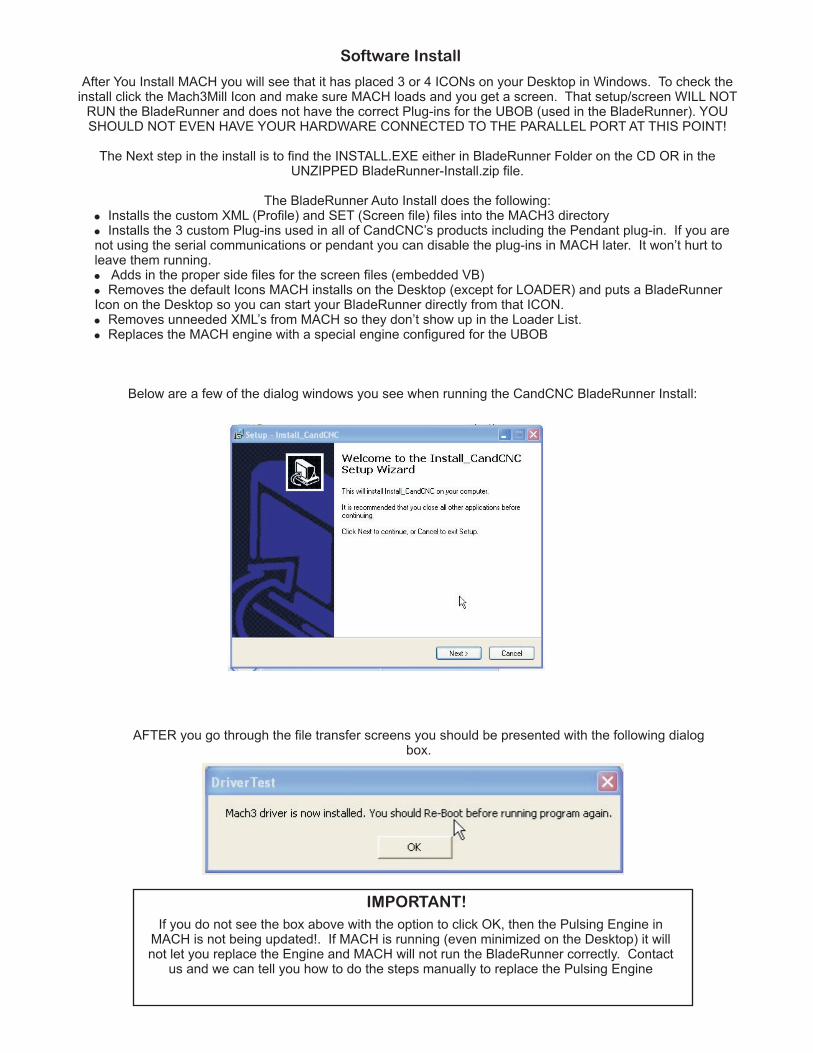
After You Install MACH you will see that it has placed 3 or 4 ICONs on your Desktop in Windows. To check theinstall click the Mach3Mill Icon and make sure MACH loads and you get a screen. That setup/screen WILL NOT
RUN the BladeRunner and does not have the correct Plug-ins for the UBOB (used in the BladeRunner). YOUSHOULD NOT EVEN HAVE YOUR HARDWARE CONNECTED TO THE PARALLEL PORT AT THIS POINT!
The Next step in the install is to find the INSTALL.EXE either in BladeRunner Folder on the CD OR in theUNZIPPED BladeRunner-Install.zip file.
The BladeRunner Auto Install does the following:Installs the custom XML (Profile) and SET (Screen file) files into the MACH3 directoryInstalls the 3 custom Plug-ins used in all of CandCNC’s products including the Pendant plug-in. If you are
not using the serial communications or pendant you can disable the plug-ins in MACH later. It won’t hurt toleave them running.
Adds in the proper side files for the screen files (embedded VB)Removes the default Icons MACH installs on the Desktop (except for LOADER) and puts a BladeRunner
Icon on the Desktop so you can start your BladeRunner directly from that ICON.Removes unneeded XML’s from MACH so they don’t show up in the Loader List.Replaces the MACH engine with a special engine configured for the UBOB
!
!
!
!
!
!
Below are a few of the dialog windows you see when running the CandCNC BladeRunner Install:
AFTER you go through the file transfer screens you should be presented with the following dialogbox.
If you do not see the box above with the option to click OK, then the Pulsing Engine inMACH is not being updated!. If MACH is running (even minimized on the Desktop) it willnot let you replace the Engine and MACH will not run the BladeRunner correctly. Contact
us and we can tell you how to do the steps manually to replace the Pulsing Engine
IMPORTANT!
Software Install

NOTE: The BladeRunner Monitor section of the screen (Lower right) will not display parameters if you do not havethe Serial Port on your PC connected to the BladeRunner Serial Input on the front panel. See the BladeRunnerUser Manual for more informatrion.
After you finish the BladeRunner Install Process:Reboot the PC and select the BladeRunner Profile by using the Desktop Icon OR from the
BladeRunner Entry in the Mach Loader list.Go to the Quik Start Section and hook up your hardware.
!
!
Software Install (Cont)
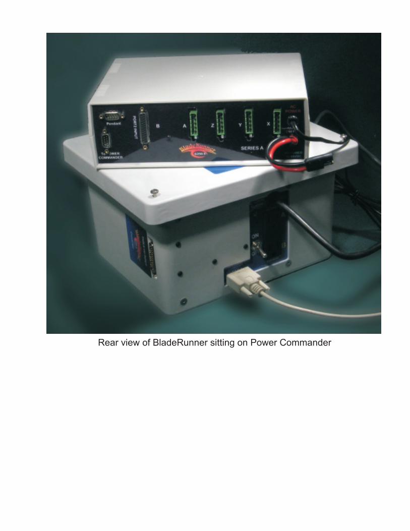
Rear view of BladeRunner sitting on Power Commander
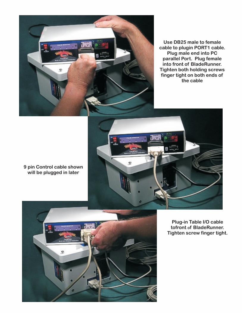
Use DB25 male to femalecable to plugin PORT1 cable.
Plug male end into PCparallel Port. Plug femaleinto front of BladeRunner.
Tighten both holding screwsfinger tight on both ends of
the cable
9 pin Control cable shownwill be plugged in later
Plug-in Table I/O cabletofront f BladeRunner.
Tighten screw finger tight.o

Plug other end of Table I/O cable intoDB25 connector on the end of the
Power Commander Box (PowerSupply)
Plug-in DB9 Power ControlCable to rear of BladeRunnerand into side panel of PowerController. You will need to
add a DB9 gender changer atone end or the other
(included). Make sure thegender changer is screwed
tightly into the matingconnector on both sides. Youmay need to remove the nutsoff the gender changer so the
thumbscrew will screw intothe male plug.
Power up sequence-----Fault LED's do a double scan on initialization.Status LED's. Both Power LED's are on and RED Stop LED is on
Plug in BladeRunner unit to ACPower up BladeRunner
Po
rt1
IN
PU
TS
ER
IAL
INP
UT
To
PC
To
PC
FA
ULT
S
Ov
er
Vo
lts
Ge
ck
o
TE
MP
LD
XY
ZA
PU
LS
E M
ON
ITO
R
Iso
late
d T
ab
le I
/O
Po
we
r
RE
C
XM
T
AC
PO
WE
R
ON
OF
F
Ca
nd
CN
C
MO
TO
R D
C
ON
OF
F
Mu
lti-
Ax
is S
tep
pe
r C
on
tro
lle
r
INP
UT
CP
G250-5
Pa
rall
el
Po
rtC
ab
le
Ta
ble
I/O
Ca
ble
Pow
er
Indic
ato
rs s
how
sta
tus o
f +
5 o
n U
BO
Band +
12 o
n U
BO
B. B
oth
LE
D’s
should
be o
nanytim
e the
AC
Pow
er
Sw
itch is O
N
RE
C 7
XM
Tlig
hts
show
sta
tus o
f S
ER
IAL
port
.Lig
hts
will
Flic
ker
slig
htly
when d
ata
is p
assin
g
FA
ULT
IND
ICA
TO
RN
orm
al S
tatu
s:
All
Off
Initia
l S
tart
up (
pow
er
ON
) tw
o s
weeps o
f th
ree R
ED
OverV
olts O
N. U
nit h
as s
hutd
ow
n d
ue to a
n o
verv
oltage
conditio
n to p
rote
ct th
e d
rives. O
verv
oltage triggers
at 58 v
olts
DC
. U
nit c
an b
e s
tart
ed a
gain
.G
ecko F
lashin
g. U
nit h
as s
hutd
ow
n d
ue to o
verload o
f one o
rm
ore
of th
e G
250 D
rives.
The n
um
ber
of flashes indic
ate
sw
hic
h d
rive/a
xis
caused the s
hutd
ow
n. O
ne fla
sh for
X; tw
o for
Y, tr
ee for
Z , e
tc. C
heck a
xis
indic
ate
d to m
ake s
ure
it is
not
jam
med. If conditio
n r
epeats
it m
ay indic
ate
a s
erious c
onditio
n.
See tro
uble
shooting s
ection for
more
help
Tem
p F
lashin
g. U
nit is lose to s
hutd
ow
n fro
m o
vert
em
p.
Turn
DC
off a
s s
oon a
s p
ossib
le. C
heck F
an insid
eTem
p S
olid
ON
. U
nit h
as s
hutd
ow
n fro
m o
ver
tem
p.
! ! ! ! ! !
CP
Lig
ht in
dic
ate
s C
harg
eP
um
pA
ctive.
Must be o
n for
Moto
rs to r
un. C
Pla
mp
does n
ot stick thro
ugh the p
anel and
may b
e h
ard
to s
ee u
nle
ss y
ou look
str
aig
ht in
PU
LS
E M
ON
ITO
RS
how
s the a
ctu
al S
tep a
nd D
irection s
ignals
at th
e G
250 C
ard
.N
o F
lash =
No S
ignal
Fla
sh R
ED
indic
ate
s S
tep p
uls
es a
nd D
IR o
f R
ED
Fla
sh G
RE
EN
indic
ate
s S
tep P
uls
es a
nd o
pposite D
IR o
f R
ED
Pro
per
sig
nals
will
puls
e a
nd c
hange c
olo
r as y
ou jog/r
un a
nd c
hange
directions
! ! ! !
MO
TO
R D
CG
RE
EN
BU
TT
ON
Turn
s o
n D
C to M
oto
rsR
ED
BU
TT
ON
Turn
s O
FF
DC
to M
oto
rsP
ow
er
off s
ends e
-sto
p to M
AC
HLE
D indic
ato
rs s
how
sta
tus o
f D
C P
OW
ER
! ! ! !
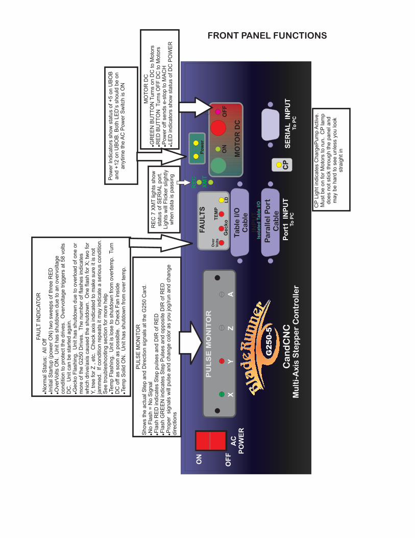
FRONT PANEL FUNCTIONS
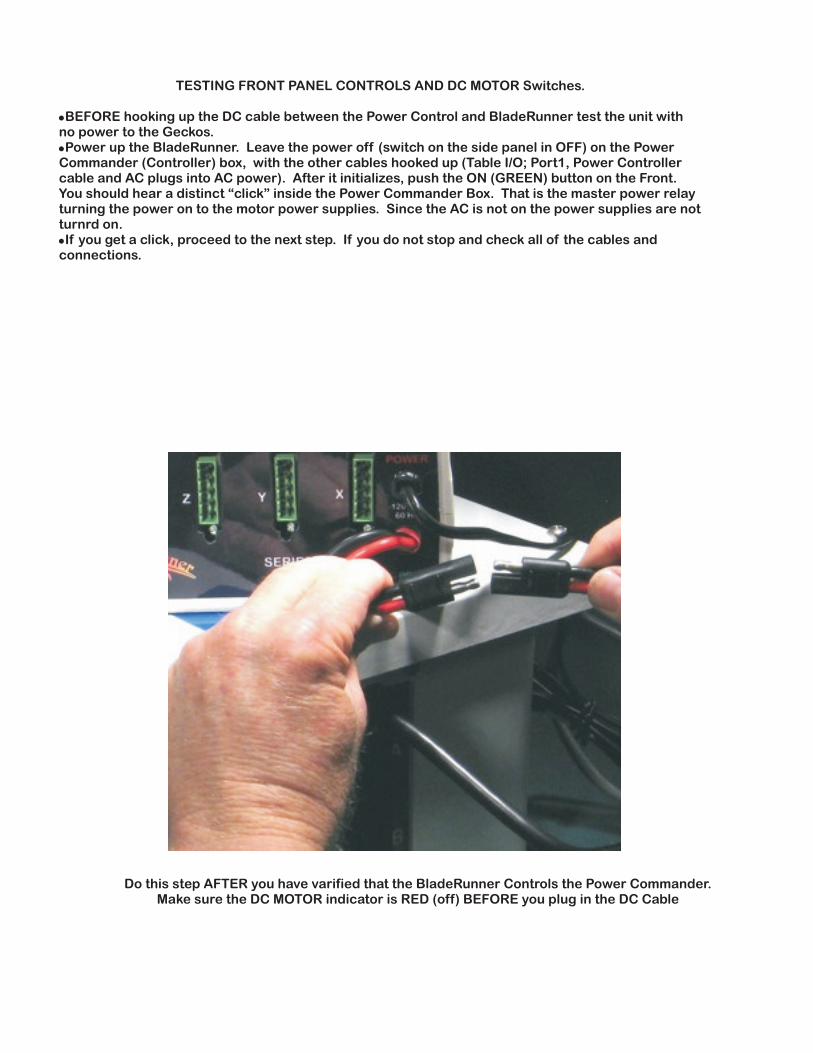
TESTING FRONT PANEL CONTROLS AND DC MOTOR Switches.
BEFORE hooking up the DC cable between the Power Control and BladeRunner test the unit withno power to the Geckos.Power up the BladeRunner. Leave the power off (switch on the side panel in OFF) on the Power
Commander (Controller) box, with the other cables hooked up (Table I/O; Port1, Power Controllercable and AC plugs into AC power). After it initializes, push the ON (GREEN) button on the Front.You should hear a distinct “click” inside the Power Commander Box. That is the master power relayturning the power on to the motor power supplies. Since the AC is not on the power supplies are notturnrd on.If you get a click, proceed to the next step. If you do not stop and check all of the cables and
connections.
!
!
!
Do this step AFTER you have varified that the BladeRunner Controls the Power Commander.Make sure the DC MOTOR indicator is RED (off) BEFORE you plug in the DC Cable
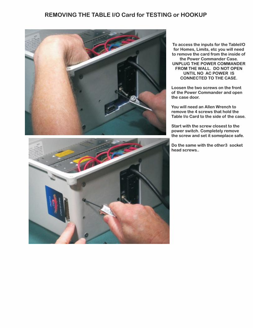
To access the inputs for the TableI/Ofor Homes, Limits, etc you will need
to remove the card from the inside ofthe Power Commander Case.
UNPLUG THE POWER COMMANDERFROM THE WALL. DO NOT OPEN
UNTIL NO AC POWER ISCONNECTED TO THE CASE.
Loosen the two screws on the frontof the Power Commander and openthe case door.
You will need an Allen Wrench toremove the 4 screws that hold theTable I/o Card to the side of the case.
Start with the screw closest to thepower switch. Completely removethe screw and set it someplace safe.
Do the same with the other3 sockethead screws..
REMOVING THE TABLE I/O Card for TESTING or HOOKUP
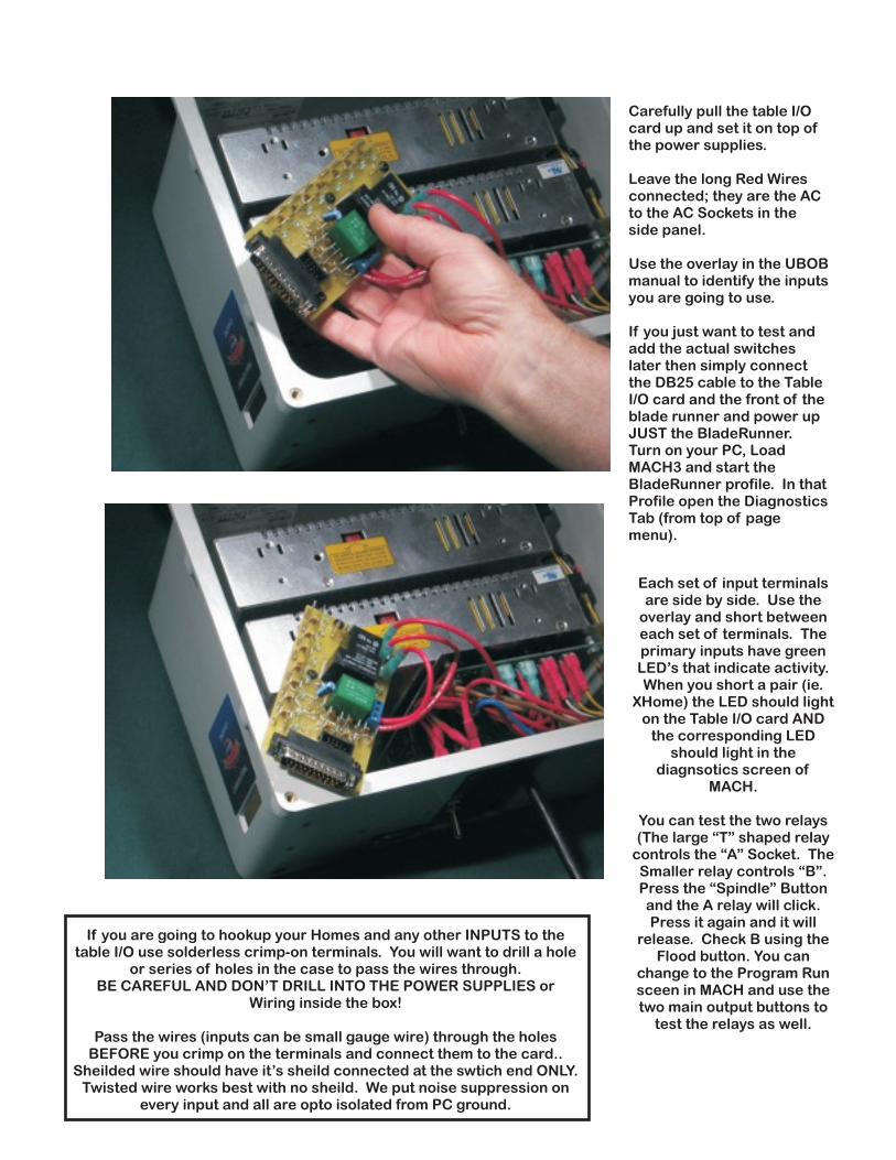
Carefully pull the table I/Ocard up and set it on top ofthe power supplies.
Leave the long Red Wiresconnected; they are the ACto the AC Sockets in theside panel.
Use the overlay in the UBOBmanual to identify the inputsyou are going to use.
If you just want to test andadd the actual switcheslater then simply connectthe DB25 cable to the TableI/O card and the front of theblade runner and power upJUST the BladeRunner.Turn on your PC, LoadMACH3 and start theBladeRunner profile. In thatProfile open the DiagnosticsTab (from top of pagemenu).
Each set of input terminalsare side by side. Use the
overlay and short betweeneach set of terminals. Theprimary inputs have greenLED’s that indicate activity.When you short a pair (ie.
XHome) the LED should lighton the Table I/O card AND
the corresponding LEDshould light in the
diagnsotics screen ofMACH.
You can test the two relays(The large “T” shaped relay
controls the “A” Socket. TheSmaller relay controls “B”.Press the “Spindle” Buttonand the A relay will click.Press it again and it will
release. Check B using theFlood button. You can
change to the Program Runsceen in MACH and use thetwo main output buttons to
test the relays as well.
If you are going to hookup your Homes and any other INPUTS to thetable I/O use solderless crimp-on terminals. You will want to drill a hole
or series of holes in the case to pass the wires through.BE CAREFUL AND DON’T DRILL INTO THE POWER SUPPLIES or
Wiring inside the box!
Pass the wires (inputs can be small gauge wire) through the holesBEFORE you crimp on the terminals and connect them to the card..
Sheilded wire should have it’s sheild connected at the swtich end ONLY.Twisted wire works best with no sheild. We put noise suppression on
every input and all are opto isolated from PC ground.
NO
NO
NO C
C
C
XHome
YHome
ZHome
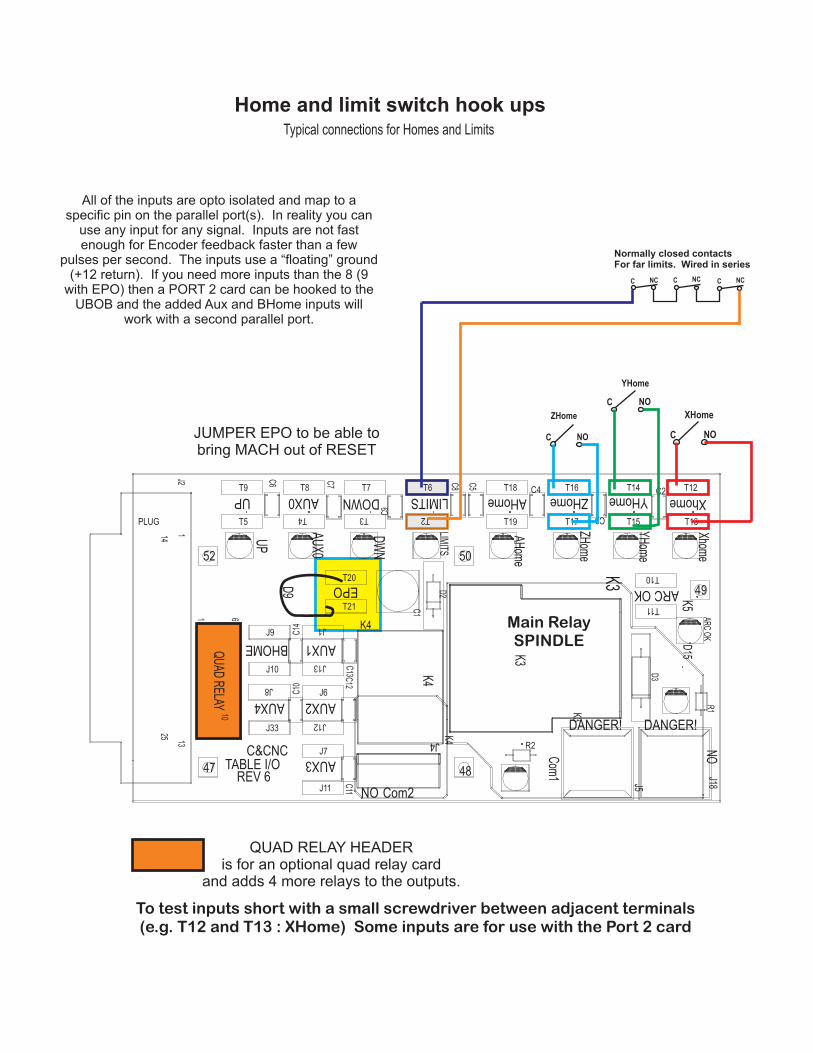
Home and limit switch hook ups
T17
K3
NO
NO
LIMIT
S
J4K
3
EPO
K4
ZHome
AUX3
AUX4
BHOME
C&CNC
47
AUX1
AHome
Com
1
K4
C2
48
AR
C O
K
TABLE I/O
DANGER!
C6
Com2
AUX2
T19
C3
REV 6
Xhome
C8
YHome
R2
K3
K4
LIMITS
K5
D3
C1
R1
C4
J33
D15
ARC OK
10
52
J18
AUX0UP
T14
T15
C5
D2
DANGER!
D9
J5
1
PLUG
J2
14
13
25
DOWN
C9
C7
YH
ome
J1
J6
J7
J8
J9
J10
50
J11
T20
T21
UP
AU
X0
DW
N
AH
ome
ZH
ome
Xhom
e
C11
C13C
12
J12
J13
T2T3T4
T5
T6T7
C14
T16
6
T8
49
T18
1
QU
AD
RE
LAY
C10
T9
T10
T11
T12
T13
NC NC NCC C C
Normally closed contactsFor far limits. Wired in series
Typical connections for Homes and Limits
All of the inputs are opto isolated and map to aspecific pin on the parallel port(s). In reality you can
use any input for any signal. Inputs are not fastenough for Encoder feedback faster than a few
pulses per second. The inputs use a “floating” ground(+12 return). If you need more inputs than the 8 (9
with EPO) then a PORT 2 card can be hooked to theUBOB and the added Aux and BHome inputs will
work with a second parallel port.
JUMPER EPO to be able tobring MACH out of RESET
QUAD RELAY HEADERis for an optional quad relay card
and adds 4 more relays to the outputs.
Main RelaySPINDLE
To test inputs short with a small screwdriver between adjacent terminals(e.g. T12 and T13 : XHome) Some inputs are for use with the Port 2 card

FINAL TESTING
After you have verified that the Power Commander Works:
Turn the BladeRunner around and with the DC Power Cable and the AC swtich on the CLOSED PowerCommander and the BladeRunner under power (Power Switch on Front Panel), Activate the ON switch(green) on the front of the BladeRunner. All of the Blades have a power indicator located below eachmotor plug on the rear.. All installed blades should have the LED illuminated.
After verifying that each blade is getting power:
TURN OFF THE DC MOTOR POWER WITH THE RED BUTTONPlug in ONE motor to the X Blade (as shown in the photo) Make sure the connector seats and
locks.Power up the DC MOTOR Power with the Green front panel button. The Motor should locked (be
hard to turn). If the motor is between poles it may jump to the nearest pole (slight bump).With MACH loaded and the BladeRunner Profile running, use the left and right arrow keys on the
keyboard to jog the X mot\or. The default jog rate is 50% of full speed. Push/hold the SHIFT keybefore you push an arrow key and the jog rate goes to 100%.Turn off the DC again and move the same motor to Y and power it back up. Test jogging Y using
the Up and Down arrow keys.Do the same thing with Z (Page Up and Page Down keys) and A (- and + on numeric pad).Hook up all of the motors and Load a G-code file (Look in MACH3/GCode folder for the Roadrunner
test file.RUN the file; listen to the “SONG of the STEPPERS” !
!
!
!
!
!
!
!
!

SETTING UP THE MPG101B Pendant.
This section to be added shortly. You will need to add a second parallel port card to your PC and get itsetup in Windows and setup in MACH (hex address). The default Hex address in the BladeRunner
Profile probably WILL NOT WORK.. The units ordered with a pendant have an installed PORT2 cardand have the Pendant plug and Port 2 input on the back of the BLadeRunner.