qzss - groups.itu.intgroups.itu.int/portals/19/activeforums_attach/4._qzss_status_update.pdf ·...
TRANSCRIPT

QZSS
RNSS Symposium on October 5, 2018 in Abuja, Nigeria
Cabinet Office, Government of Japan

Contents
1. QZSS Overview
Services
System Architecture
Development Status
2. Recent Development
QZSS Performance
SBAS Service and Experiments
QZSS Satellite Information
3. International Cooperation
4. Summary
2
40 50
60
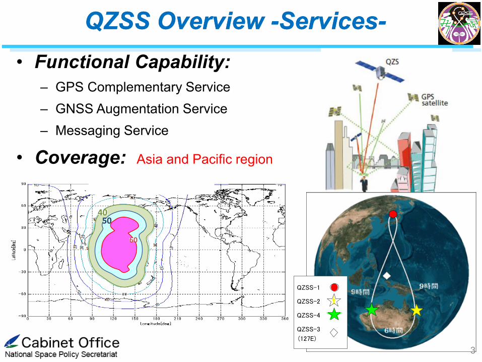
• Functional Capability:
– GPS Complementary Service
– GNSS Augmentation Service
– Messaging Service
• Coverage: Asia and Pacific region
QZSS-1
QZSS-2
QZSS-4
QZSS-3
(127E)
3
QZSS Overview -Services- QZSS Overview -Services-

• Coverage: Asia and Pacific region
40
50
60
QZSS Overview -Services- QZSS Overview -Services-
Minimum Largest Elevation Angle Contour in the QZSS 4SV Constellation
4

QZSS improves positioning
availability
• Navigation signals L1-C/A, L1C,
L2C, and L5 coming from high
elevation (near zenith) improve
PNT availability.
• QZSS is the first L1C and L5
signals provider offering inter-
operability among other GNSS.
• SIS-URE: 2.6m (95%)
QZS
GPS
Functional Capability 1 GPS Complementary Service Functional Capability 1 GPS Complementary Service
QZSS Overview -Services- QZSS Overview -Services-
5

QZSS improves positioning accuracy and reliability
Functional Capability 2 GNSS Augmentation Service Functional Capability 2 GNSS Augmentation Service
Augmentation Data Generation
GNSS Earth Observation Network
QZSS
Navigation Signal
Galileo GPS GLONASS
Global Monitoring Stations L6 L1S centimeter (accuracy ) sub-meter
Navigation Signal and Augmentation Data
Ground Segment
User Segment
QZSS Overview -Services- QZSS Overview -Services-
6

Sub-meter Level Augmentation Service: SLAS
Functional Capability 2 GNSS Augmentation Service Functional Capability 2 GNSS Augmentation Service
Augmentation Data Generation
Reference Stations
QZSS
Ground Segment
Using GPS only ~ 10m
Sub-meter level Augmentation Data L1S (250 bps)
Using QZSS Augmentation Signal
~ 2m
Differential code phase positioning
H 1.0 m (95%), V 2.0 m (95%)
Domestic Service
QZSS Overview -Services- QZSS Overview -Services-
7
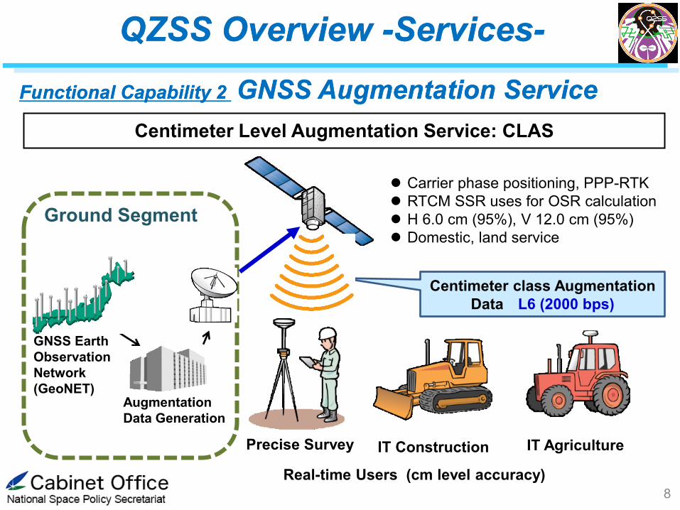
Centimeter Level Augmentation Service: CLAS
Functional Capability 2 GNSS Augmentation Service Functional Capability 2 GNSS Augmentation Service
Augmentation
Data Generation
GNSS Earth
Observation
Network
(GeoNET)
QZSS
Ground Segment
Real-time Users (cm level accuracy)
Centimeter class Augmentation
Data L6 (2000 bps)
Precise Survey IT Construction IT Agriculture
Carrier phase positioning, PPP-RTK
RTCM SSR uses for OSR calculation
H 6.0 cm (95%), V 12.0 cm (95%)
Domestic, land service
QZSS Overview -Services- QZSS Overview -Services-
8

9
QZSS Overview -Services- QZSS Overview -Services-
Functional Capability 3 Messaging Service Functional Capability 3 Messaging Service
Satellite Report for Disaster and Crisis Management (DC Report)
Disaster Info. Disaster Info.
Japan Meteorological Agency (JMA)
Ground Control Segment
QZSS
Using one of four slots of L1S:1575.42MHz,
once a four seconds, 250 bits short code can
transmits disaster management info with
applicable location
Using one of four slots of L1S:1575.42MHz,
once a four seconds, 250 bits short code can
transmits disaster management info with
applicable location
Disaster Info. provided by JMA such
as Tsunami, Volcanic eruption,
weather warning and so on.
DC Report available Handset (GNSS Rx, Car Navigation device)
Rx can select the Info which shown the devices
depending on their location
Using margin of L1S signal
Same service coverage as GPS
complementary service

10
QZSS Overview -Services- QZSS Overview -Services-
Functional Capability 3 Messaging Service Functional Capability 3 Messaging Service
QZSS Safety Confirmation Service (Q-ANPI)
Disaster organization, Municipal government
Ground
Control
Segment
#3 QZS (GEO)
Collected Info is
browsed at web-site
via Internet
Q-ANPI
Terminal
Wifi, BLE
Evacuation shelter
Using Smartphone App, Info such as shelter’s capacity, shorten
resources, safety of evacuee collected and sent to the Q-ANPI
center via QZS-3
Two-way S-band Com. link
Only #3 QZS (GSO SV) has capability
to provide Q-ANPI
Domestic service
This service is available on S-band devices that support Q-ANPI, Q-ANPI terminal. This service is available on S-band devices that support Q-ANPI, Q-ANPI terminal.
Contents
1. QZSS Overview
Services
System Architecture
Development Status
2. Recent Development
QZSS Performance
SBAS Service and Experiments
QZSS Satellite Information
3. International Cooperation
4. Summary
11

• Constellation:
– 1 GEO Satellite, 127E
– 3 QZO Satellite (IGSO)
• Ground System
– 2 Master Control Stations
• Hitachi-Ota and Kobe
– 7 Satellite Control Stations
• Located south-western islands
– Over 30 Monitor Stations around
the world
QZSS Overview -System- QZSS Overview -System-
Equator
12
13
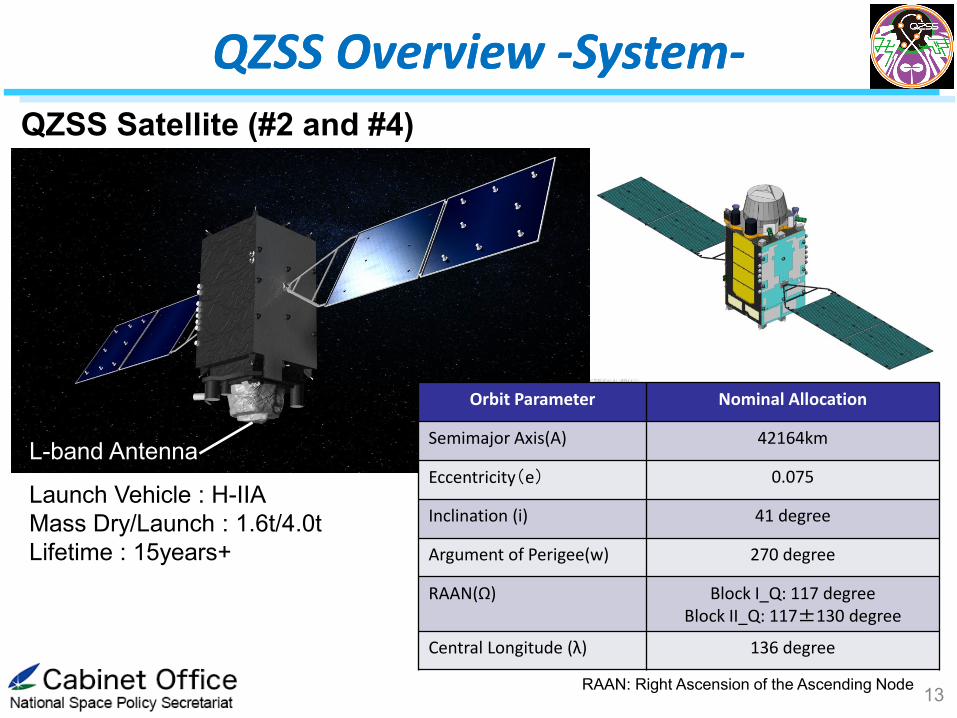
QZSS Overview -System- QZSS Overview -System-
L-band Antenna
QZSS Satellite (#2 and #4)
Orbit Parameter Nominal Allocation
Semimajor Axis(A) 42164km
Eccentricity(e) 0.075
Inclination (i) 41 degree
Argument of Perigee(w) 270 degree
RAAN(Ω) Block I_Q: 117 degree Block II_Q: 117±130 degree
Central Longitude (λ) 136 degree
RAAN: Right Ascension of the Ascending Node
Launch Vehicle : H-IIA
Mass Dry/Launch : 1.6t/4.0t
Lifetime : 15years+

14
QZSS Overview -System- QZSS Overview -System-
QZSS Satellite (#3 GEO)
S-band Antenna
Orbit Parameter Nominal Allocation
Longitude E 127
Latitude 0
Launch Vehicle : H-IIA
Mass Dry/Launch : 1.8t/4.7t
Lifetime : 15years+
• Additional S-band antenna for two-way communication for emergency safety
report (Q-ANPI service).
• L1Sb signal for SBAS service.

QZSS Overview -System- QZSS Overview -System-
15
QZSS Master Ground Station
Two-Ground Station (Control Center)are available with site diversity.
Hitachi-Ota station is main operation site and Kobe is a redundant site.
QZSS Control Center, Kobe
QZSS Control Center, Hitachi-Ohta,
http://www.mlit.go.jp/koku/15_bf_000367.html
http://www.mlit.go.jp/koku/15_bf_000367.html

16
• 7 TTC (Telemetry, Tracking, and Command) stations: Most are at the southern part of Japan for satellite continuous visibility.
• All TTC stations were built and set operational by the end of 2016.
宮古島
石垣島
久米島
種子島
常陸太田
沖縄宇宙通信所
常陸太田
神戸
Hitachi Ota
Kobe
Tanegashima Is.
Okinawa Is.
Miyako Is. Ishigaki Is.
Kume Is.
QZSS TTC Stations
QZSS Overview -System- QZSS Overview -System-

QZSS Overview -System- QZSS Overview -System-
17
:Monitor Site
Wellington
Istanbul
Johannesburg Brisbane
Perth
Manila
Jakarta
Kandy
Bangkok
Kobe Sapporo
Mauritius
Miyako Isd
Lethbridge
Maspalomas
Tromso
Sao Paulo
Santiago
Fiji Darwin
Panama
Makassar Singapore
Dubai
25 monitor stations for POD of both QZSS and GPS satellites
Additional 10 domestic stations for SLAS (totally 13 sites)
CLAS uses GEONET, Japanese CORS more than 1200 stations
QZSS Monitor Stations Distribution
Inuvic
QZSS Overview -System- QZSS Overview -System-
18
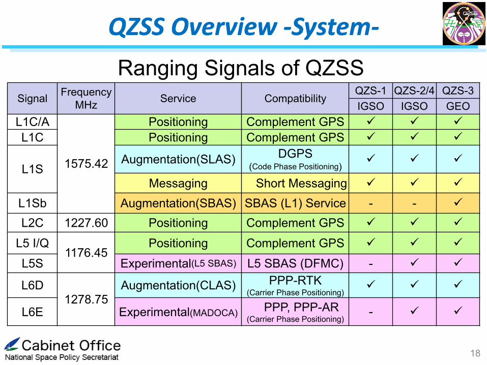
Signal Frequency
MHz Service Compatibility
QZS-1 QZS-2/4 QZS-3
IGSO IGSO GEO
L1C/A
1575.42
Positioning Complement GPS
L1C Positioning Complement GPS
L1S Augmentation(SLAS) DGPS
(Code Phase Positioning)
Messaging Short Messaging
L1Sb Augmentation(SBAS) SBAS (L1) Service - -
L2C 1227.60 Positioning Complement GPS
L5 I/Q 1176.45
Positioning Complement GPS
L5S Experimental(L5 SBAS) L5 SBAS (DFMC) -
L6D 1278.75
Augmentation(CLAS) PPP-RTK (Carrier Phase Positioning)
L6E Experimental(MADOCA) PPP, PPP-AR
(Carrier Phase Positioning) -
Ranging Signals of QZSS

QZSS Overview -System- QZSS Overview -System-
19
Interface Documents Interface Documents
Performance Standard (PS-QZSS) and Interface
Specification (IS-QZSS) are available in our website
http://qzss.go.jp/en/technical/ps-is-qzss/ps-is-qzss.html

Contents
1. QZSS Overview
Services
System Architecture
Development Status
2. Recent Development
QZSS Performance
SBAS Service and Experiments
QZSS Satellite Information
3. International Cooperation
4. Summary
20

QZSS Program Schedule (latest)
QZSS Overview -Development Status- QZSS Overview -Development Status-
21
JFY H27
(2015) )
H28
(2016)
H29
(2017) )
H30
(2018)
H31
(2019)
H32
(2020)
H33
(2021)
H34
(2022)
H35~
(2023~)
1st Michibiki
QZSS
4-Sat.
Constellation
QZSS
7-Sat.
Constellation
QZSS Service
Development / Design (Additional 3 Sats.) Development / Design (Additional 3 Sats.) QZSS Service
In-Operation In-Operation
Replacement of Michibiki Launch No.1R satellite
Launch No.2,3,4
SBAS Service

Three consecutive launches: Ready for service-in! Three consecutive launches: Ready for service-in!
QZSS Overview -Development Status- QZSS Overview -Development Status-
22
#2 satellite: Jun. 1, 2017
00:17:46(UCT)
#3 satellite: Aug. 19, 2017
05:29:00(UTC) #4 satellite: Oct. 9, 2017
22:01:37 (UTC)
©三菱重工/JAXA

Contents
1. QZSS Overview
Services
System Architecture
Development Status
2. Recent Development
QZSS Performance
SBAS Service and Experiments
QZSS Satellite Information
3. International Cooperation
4. Summary
23

QZSS Performance -PNT Service- QZSS Performance -PNT Service-
24
▌Performance(SIS Accuracy)
[ Specification ] less than 2.6m(95%)
[ Evaluation (2018/5/11~ 2018/5/17) ]
QZS-1: 0.61m(95%), QZS-2: 1.11m(95%), QZS-3: 0.96m(95%), QZS-4: 1.01m(95%)
▌The improvement by the tuning
In order to improve SIS Accuracy (i.e. orbit error and clock error), parameters in our estimation
engine were adjusted.
Before the tuning of QZS-2 After the tuning of QZS-2

QZSS Performance -SLAS Service- QZSS Performance -SLAS Service-
25
▌Service Area of SLAS
▌Accuracy of SLAS
Sapporo
Sendai
Hitachi-ohta
Komatsu
Kobe
Hiroshima
Fukuoka
Tanegashima
Amami
Itoman
Miyako-jima
Ishigaki-jima
Chichi-jima
monitoring station:
Service Area is the area surrounded by the red line.
The left-axis is latitude, and lower-axis is longitude.
positioning errorm(95%) Remarks
horizontal vertical
≤ 1.0 m ≤ 2.0 m
EL mask : 10°
User range error caused by user’s receivers and
user’s situation : 0.87 m(95%)
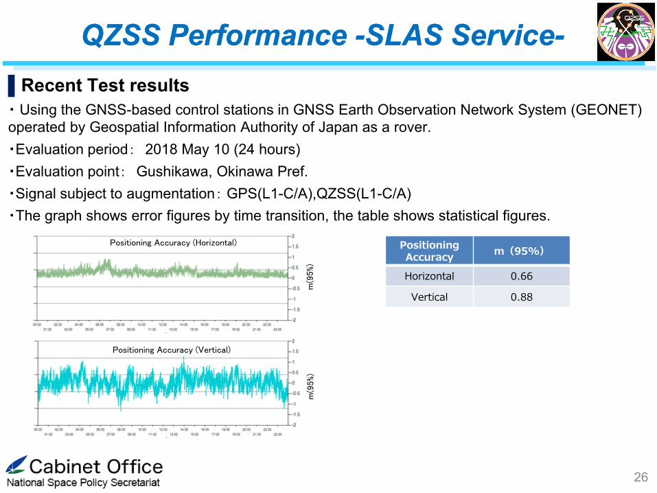
▌Recent Test results
・ Using the GNSS-based control stations in GNSS Earth Observation Network System (GEONET)
operated by Geospatial Information Authority of Japan as a rover.
・Evaluation period: 2018 May 10 (24 hours)
・Evaluation point: Gushikawa, Okinawa Pref.
・Signal subject to augmentation: GPS(L1-C/A),QZSS(L1-C/A)
・The graph shows error figures by time transition, the table shows statistical figures.
QZSS Performance -SLAS Service- QZSS Performance -SLAS Service-
26
Positioning Accuracy
m(95%)
Horizontal 0.66
Vertical 0.88 m
(95%)
m(9
5%)
Positioning Accuracy (Vertical)
Positioning Accuracy (Horizontal)

QZSS Performance -CLAS Service- QZSS Performance -CLAS Service-
27
3.Servicing situation
1) Present: Test service on running
2) From 1st Nov 2018: Public service distribution
・Range of service: Japanese domain and
800,000km2 area off shore
・Accuracy:
H ≤ 6.0 cm (95%), V ≤ 12.0 cm (95%) (Static)
H ≤ 12.0 cm (95%), V ≤ 24.0 cm (95%) (Kinematic)
4.Examples of use and demonstration
1) Automobile
Precise positioning used in
combination with HD Maps
for automated control
2) Agriculture
Precise positioning
used for automated control
of tractors
3) Snowplough
Assists recognition of self
position in comparison with
HD maps
2.Technical features
1)Augmentation data is created from CORS data
2)Error resulting from Ionosphere, Troposphere
conditions can be corrected
3)Augmentation data is broadcasted from QZSS
free of charge
Positioning Signal
Altitude
500km
CORS
(Continously Operationg
Reference Station)
Users
①Error in Positioning
Signals
④
④
Space & On-Ground Infrastructure
for High-Precision Positioning
Quasi-Zenith Satellite System
(QZSS: JPN)
④ Positioning errors
corrected by
each receiver
②Create augmentation
data and compress
③Broadcast via satellite
(or on ground
communication)
GNSS
1.CLAS (Centimeter Level Augmentation Service)
Orbit clock,
Biases,
Ionosphere,
Troposphere
Server and facility
for CLAS
QZSS Performance -CLAS Service- QZSS Performance -CLAS Service-
28
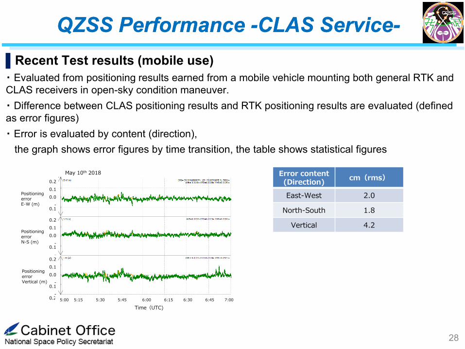
▌Recent Test results (mobile use)
・ Evaluated from positioning results earned from a mobile vehicle mounting both general RTK and
CLAS receivers in open-sky condition maneuver.
・ Difference between CLAS positioning results and RTK positioning results are evaluated (defined
as error figures)
・ Error is evaluated by content (direction),
the graph shows error figures by time transition, the table shows statistical figures
Error content (Direction)
cm(rms)
East-West 2.0
North-South 1.8
Vertical 4.2
May 10th 2018
0.2
0.1
0.0
-0.1
-
0.2 0.2
0.1
0.0
-0.1
-
0.2 0.2
0.1
0.0
-0.1
-
0.2
Time(UTC)
Positioning error E-W (m)
5:00 5:15 5:30 5:45 6:00 6:15 6:30 6:45 7:00
Positioning error N-S (m)
Positioning error Vertical (m)

Contents
1. QZSS Overview
Services
System Architecture
Development Status
2. Recent Development
QZSS Performance
SBAS Service and Experiments
QZSS Satellite Information
3. Summary
29

30
MSAS: Japanese SBAS MSAS: Japanese SBAS
Ranging Signals
GPS Satellites
Ground
Network
Naha GMS
Fukuoka GMS
Tokyo
GMS
Sapporo
GMS
Hitachi-Ota MCS
(and GMS)
Kobe MCS
(and GMS)
Users
MTSAT-2
Augmentation Signals
MSAS: Japanese SBAS in operation.
Operational since Sept. 27, 2007.
Currently operated by JCAB with a GEO called MTSAT-2.
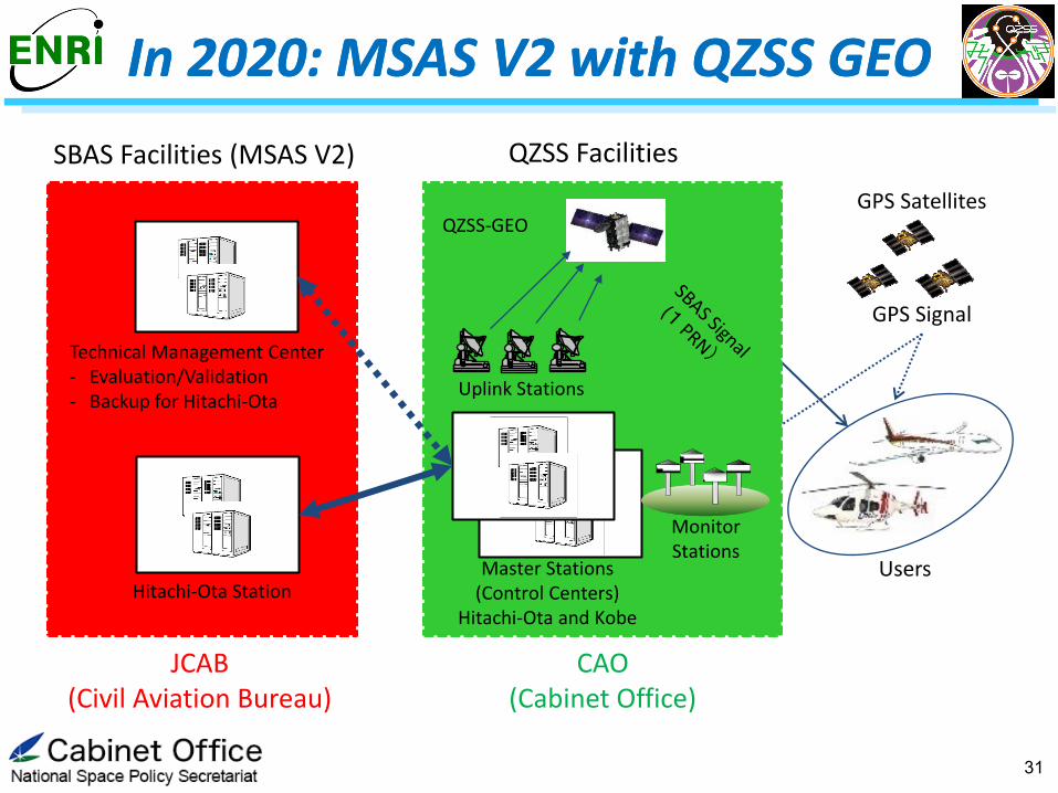
SBAS Facilities (MSAS V2)
Hitachi-Ota Station
GPS Signal
GPS Satellites
JCAB (Civil Aviation Bureau)
CAO (Cabinet Office)
QZSS Facilities
Master Stations (Control Centers)
Hitachi-Ota and Kobe
Uplink Stations
Monitor Stations
QZSS-GEO
Users
Technical Management Center - Evaluation/Validation - Backup for Hitachi-Ota
31
In 2020: MSAS V2 with QZSS GEO In 2020: MSAS V2 with QZSS GEO

32
MSAS V2 RF Performance MSAS V2 RF Performance
MSAS-v2 RF Spectrum
PRN 129 and PRN 137 are transmitted from MTSAT-2 (MSAS-v1).
PRN 187 is currently transmitted from QZS-3 GEO; Will be switched to
PRN 129 or 137 for MSAS-v2.
Current MSAS
MSAS V2
Current MSAS
MSAS V2
30 MHz
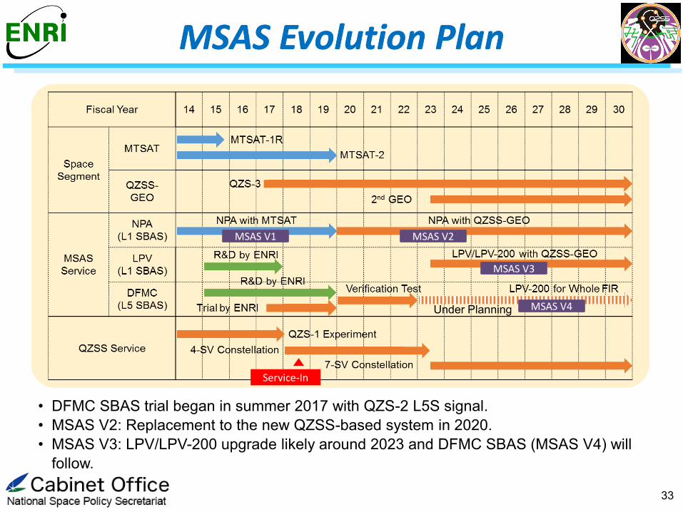
• DFMC SBAS trial began in summer 2017 with QZS-2 L5S signal.
• MSAS V2: Replacement to the new QZSS-based system in 2020.
• MSAS V3: LPV/LPV-200 upgrade likely around 2023 and DFMC SBAS (MSAS V4) will
follow.
33
MSAS Evolution Plan MSAS Evolution Plan
MSAS V1 MSAS V2
MSAS V3
MSAS V4 Under Planning
Service-In
34
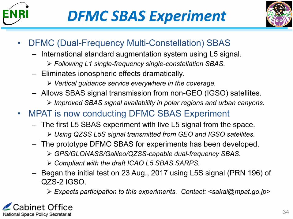
• DFMC (Dual-Frequency Multi-Constellation) SBAS
– International standard augmentation system using L5 signal.
Following L1 single-frequency single-constellation SBAS.
– Eliminates ionospheric effects dramatically.
Vertical guidance service everywhere in the coverage.
– Allows SBAS signal transmission from non-GEO (IGSO) satellites.
Improved SBAS signal availability in polar regions and urban canyons.
• MPAT is now conducting DFMC SBAS Experiment
– The first L5 SBAS experiment with live L5 signal from the space.
Using QZSS L5S signal transmitted from GEO and IGSO satellites.
– The prototype DFMC SBAS for experiments has been developed.
GPS/GLONASS/Galileo/QZSS-capable dual-frequency SBAS.
Compliant with the draft ICAO L5 SBAS SARPS.
– Began the initial test on 23 Aug., 2017 using L5S signal (PRN 196) of
QZS-2 IGSO.
Expects participation to this experiments. Contact: <[email protected]>
DFMC SBAS Experiment DFMC SBAS Experiment

35
• Supports DFMC
• Provides observation in
real time
• Operates in real time
• Supports GPS+GLONASS
+Galileo+QZSS
• Relays L5S
message data
ENRI L5 SBAS
Prototype GEONET QZSS C&C
Meas.
Data L5 SBAS
Message
GSI
(Shinjuku, Tokyo)
ENRI, MPAT (Chofu, Tokyo)
QZSS MCS (Hitachi-Ota, Ibaraki)
QZSS
#2, #3, and #4 GLONASS
GPS Galileo
BeiDou
GEO (QZS-3) +
IGSO (QZS-2/4)
System Configuration System Configuration
36
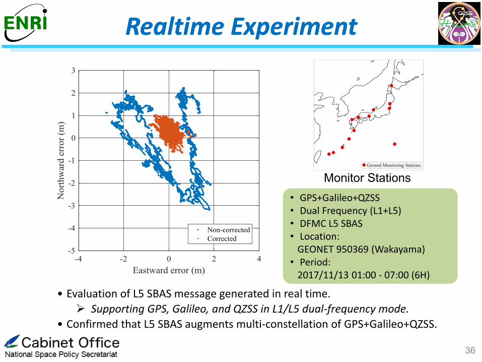
• GPS+Galileo+QZSS • Dual Frequency (L1+L5) • DFMC L5 SBAS • Location: GEONET 950369 (Wakayama) • Period: 2017/11/13 01:00 - 07:00 (6H)
• Evaluation of L5 SBAS message generated in real time.
Supporting GPS, Galileo, and QZSS in L1/L5 dual-frequency mode.
• Confirmed that L5 SBAS augments multi-constellation of GPS+Galileo+QZSS.
Monitor Stations
Realtime Experiment Realtime Experiment

A precise positioning methodology obtaining absolute location with deci-meter level
Resolving Integer ambiguity of carrier phase is called “PPP-AR” which can reach a couple
of cm level solution.
①satellite orbit and clock error
②Ionospheric delay error
③Tropospheric delay error
④Noise・Multipath
Relative position wrt. reference station
Double Difference between satellites and ref
stations cancels errors above shown ①②③
cm level accuracy with instant convergence time
Dense reference network required
Absolute position
Precise orb and clk are indispensable
Iono-error ② is canceled by using Iono-free
combination or estimated by using some models
cm(PPP-AR)~deci meter (PPP) accuracy but
long convergence time (30-40 minutes)
Global coverage with global ref. network
Reference station
Precise Point Positioning (PPP)
RTK PPP/PPP-AR
main error sources
37
PPP Experiment using MADOCA PPP Experiment using MADOCA

38
QZSS orbit
QZSS
QZSS cover area
• CLAS (Centimeter Level
Augmentation Service) will be
provided via L6D signal.
• Employs the dense GNSS
monitoring network in service
area.
• CLAS for Japanese territory
begins in 2018.
• Service for other regions is under
consideration.
:region
• Experimental augmentation based
on PPP with MADOCA will be
conducted using L6E signal on
QZS-2/3/4.
• MADOCA: Multi-GNSS Advanced
Demonstration tool for Orbit and
Clock Analysis.
• Global GNSS monitoring network.
• Will also begin in 2018.
:region
CLAS on L6D MADOCA-PPP
on L6E
CLAS
MADOCA-PPP
CLAS Service and MADOCA Experiment CLAS Service and MADOCA Experiment

Contents
1. QZSS Overview
Services
System Architecture
Development Status
2. Recent Development
QZSS Performance
SBAS Service and Experiments
QZSS Satellite Information
3. International Cooperation
4. Summary
39
• Considering ICG WG-D recommendation and IGS White Paper, Satellite Property Information (SPI) and Operational History Information (OHI) for each QZS SV was published on our web-site.
http://qzss.go.jp/en/technical/qzssinfo/index.html
• Following info are included;
40
QZSS Satellite Information QZSS Satellite Information
■Satellite Property Information(SPI)
• Reference Frame
• Attitude Law
• Mass and Center of Mass
• Navigation Antenna Phase Center Corrections
• Geometry
• Satellite dimension
• Optical Property
• Laser Retro Reflector Location
• Differential Code Bias
■Operational History Information(OHI)
• Attitude Change history
• mode/start・end
• Orbit maintenance maneuver history
• time/duration/delta-V/direction
• Estimated mass history

Contents
1. QZSS Overview
Services
System Architecture
Development Status
2. Recent Development
QZSS Performance
SBAS Service and Experiments
QZSS Satellite Information
3. International Cooperation
4. Summary
41

International Collaboration International Collaboration
42
JP-US Continuous discussion on Interference Mitigation on L1C/A
Cooperation on Ground Segment (Monitoring Site) for future extension
JP-EU Cooperation Agreement relative to Satellite Navigation Applications
between Japan (National Space Policy Secretariat, Cabinet Office) and EU
(DG-Glow, European Commission) was established on March 8, 2017.
• Annual Round Table and Working Group discussions
• Emergency Warning Services, Autonomous driving and 3D mapping, E6/L6 signals,
DFMC SBAS, Knowledge sharing about Operations
Current Activities
• Definition of common EWS message format is on going.
• Galileo-QZSS joint EWS trial in Australia was successfully completed on 19 Sept.
• Joint working team activity will begin soon: Joint R&D activity on DFMC SBAS
supporting IGSO SBAS concept will be planned.
Summary
QZSS is Japanese regional satellite navigation system to
improve not only GNSS availability but also accuracy
and reliability.
4 satellite constellations: Three IGSO and one GEO satellites.
Three consecutive launches have successfully been conducted
in 2017; All four satellites are now ready on their orbits.
Operational Service begins on November 1, 2018.
GPS complement service, GNSS augmentation service including
SBAS, and messaging service.
Precise positioning service can be utilized in many applications
with Multiple GNSS as well as multi-sensors.
Some experiments including DFMC SBAS and PPP are also
ongoing.
43

For more information, please visit our web site
http://qzss.go.jp/en/
For more information, please visit our web site
http://qzss.go.jp/en/
Thank you for your attention.
44

Backup: IGSO SBAS Concept Backup: IGSO SBAS Concept
45
• DFMC SBAS could be transmitted by non-GEO satellites like QZSS IGSO.
• Transmission from the Zenith: Improves availability of augmentation signals
where GEO signal is blocked.
Polar regions, mountain area, urban canyons, building on the south
side, approaching aircraft, and so on.
QZSS-IGSO GEO