r cooling research scoping study - …cbe.berkeley.edu/research/pdf_files/ir_radcoolscoping...page 2...
TRANSCRIPT
INTERNAL REPORT APRIL 2006
RADIANT COOLING RESEARCH SCOPING STUDY
Timothy Moore, Fred Bauman, and Charlie Huizenga Center for the Built Environment (CBE) University of California, Berkeley
April 20, 2006
1. BACKGROUND
1.1 OBJECTIVE
The objective of this project is to characterize the opportunities and limitations of radiant cooling strategies for North America and identify research needs that CBE might most effectively address. Based on literature, case studies, and interviews with experienced designers, CBE has set out to determine the focus of radiant cooling research that will best address shortcomings of industry resources and thus provide the most benefit to CBE partners.
1.2 RADIANT COOLING
Radiant cooling uses actively cooled surfaces to absorb excess thermal energy and remove it from a space. This is more or less the inverse of the radiant floor heating systems that have become relatively popular in North American residential applications. In the case of radiant cooling, thermal energy is flowing from the occupants, equipment, lights, and other surfaces in the room to the actively cooled surface. As long as the cooled surface is at a lower temperature than other surfaces in the room, heat will flow to it from all higher temperature surfaces accessible by line of sight. The radiant exchange itself has negligible effect on air temperature. However, some air in the occupied space is cooled when it comes in contact with the active surface and any other surface indirectly cooled by radiant exchange with the active surface.
Once having been absorbed by the actively cooled surface, heat is removed by water flowing through a hydronic circuit thermally coupled to the surface. Since there are typically internal latent loads (humidity) from occupants and infiltration, plus sensible and latent loads associated with outside ventilation air, radiant cooling is often part of a hybrid system that includes conditioning of ventilation air to address these loads. In some designs conditioned air provides a significant means of addressing thermal loads in occupied spaces. Many of the potential advantages and challenges related to radiant cooling are associated with the shift toward hydronic systems and away from typical airside systems. Therefore it is important to consider how each of these is affected.

PAGE 2 Radiant Cooling Research Scoping Study April 2006
In terms of achieving thermal comfort in cooling mode, system design and control strategies are often intended to operate with slightly warmer-than-typical interior air temperatures and relatively cooler surfaces as compared to conventional all-air systems. Roughly speaking, a one-degree reduction in surface temperatures can offset a one-degree increase in air temperature. Other strategies are aimed at supporting natural ventilation or mixed-mode operation.
1.3 FOCUS
This research is focused on hydronic radiant cooling for commercial and institutional buildings. Radiant cooling refers to any system where surrounding surface temperatures are lowered to remove sensible thermal loads from a conditioned space and its occupants, thus providing or contributing to thermal comfort. The technology encompasses a broad range of applications, system design strategies, and technologies. The principal system types investigated in this project are hydronic radiant slabs and suspended radiant panels, inclusive of hybrid systems for which these are the primary means of space conditioning. Because slab-integrated radiant cooling systems with significant thermal mass, often referred to as thermo-active slabs, appear less well understood in North America, this report discusses them in somewhat greater depth. Passive chilled beams with a significant radiant component are within the scope of radiant cooling systems studied. An actively controlled surface is considered a “radiant panel” if at least 50% of the design heat transfer is by thermal radiation (2004 ASHRAE Handbook).
Active chilled beams, fan coils, and similar hydronic terminal devices that provide cooling primarily through convection and induction are considered herein only as supplementary technologies that may be part of a hybrid system. Hydronic and electric-resistance radiant heating are considered only where they are an alternate seasonal function of an otherwise cooling-dominated system or a supplementary heat source for local adjustment of thermal comfort. Airside systems, ventilation, and conditioning of outside air are discussed within the context of systems where radiant exchange is the primary means of space conditioning.
2. CHARACTERIZATION
The basic radiant cooling system types are chilled slabs and panels. While panels have advantages related to zoning and installation flexibility, responsiveness, and control, slabs have advantages of lower cost per unit area of active surface and better coupling with the thermal mass of the building structure. Each of these primary system characteristics comes with a range of associated potential advantages and disadvantages, synergies, benefits, and challenges. These are described in subsequent sections of this report.
The following generalized characteristics are representative of typical design strategies and applications for slab vs. panel radiant cooling. There are many other variants possible and considerations worthy of discussion. These are intended to highlight some of the defining differences between the two primary system types.
PAGE 3 Radiant Cooling Research Scoping Study April 2006
2.1 SLAB-INTEGRATED SYSTEMS
Depending on the design, the exposed surface of an active radiant cooling slab can be a floor or ceiling, or may even include walls. Generally, an overhead active surface is most effective, particularly in removing heat gain from an occupied space. Reasons for this include the relative effectiveness of exposed thermal mass in ceilings vs. floors and the likelihood that furnishings and/or carpet will significantly attenuate radiant exchange (ASHRAE Handbook 2004). Exceptions include spaces with very high ceilings, spaces with no carpet and little or no furnishings, or designs wherein direct-beam solar gain is to be removed from the floor slab or light shelf receiving it.
Typical characteristics and applications of slab-integrated systems
Significant thermal mass and associated thermal lag and inertia Low cost per unit surface area Larger active surfaces as a function of low cost and integration with structure Surface temperatures of 64–75°F (18–24°C) for the entire cooling-to-heating range Relatively lower sensible cooling capacity on the order of 24 Btu/hr-ft2 (~7 W/ft2 or 77 W/m2)
active surface, not including associated ventilation systems or strategies Ventilation supply air normally just below space temperature Better suited to buildings with high-performance envelopes, moderate climates, or use with
natural ventilation and/or low-energy cooling (heating) sources Operation most often addresses loads first with radiant exchange and secondarily with
conditioned ventilation air (except during airside economizer operation or natural cooling in mixed-mode buildings)
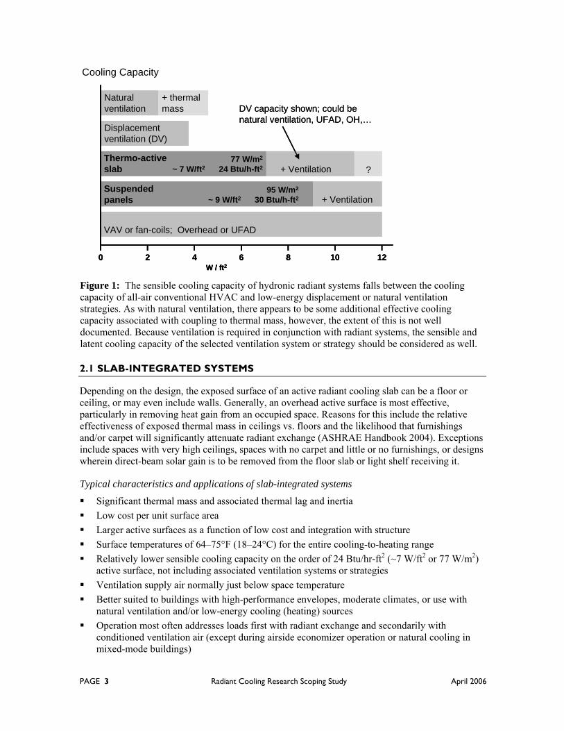
Figure 1: The sensible cooling capacity of hydronic radiant systems falls between the cooling capacity of all-air conventional HVAC and low-energy displacement or natural ventilation strategies. As with natural ventilation, there appears to be some additional effective cooling capacity associated with coupling to thermal mass, however, the extent of this is not well documented. Because ventilation is required in conjunction with radiant systems, the sensible and latent cooling capacity of the selected ventilation system or strategy should be considered as well.
Cooling Capacity
Thermo-active slab
Displacement ventilation (DV)
VAV or fan-coils; Overhead or UFAD
Natural ventilation
77 W/m2
~ 7 W/ft2 24 Btu/h-ft2
Suspended panels
+ Ventilation
+ Ventilation
DV capacity shown; could be natural ventilation, UFAD, OH,…
0 2 4W / ft2
6 8 10 12
95 W/m2
~ 9 W/ft2 30 Btu/h-ft2
+ thermal mass
?Thermo-active slab
Displacement ventilation (DV)
VAV or fan-coils; Overhead or UFAD
Natural ventilation
77 W/m2
~ 7 W/ft2 24 Btu/h-ft2
Suspended panels
+ Ventilation
+ Ventilation
DV capacity shown; could be natural ventilation, UFAD, OH,…
0 2 4W / ft2
6 8 10 120 2 4W / ft2
6 8 10 12
95 W/m2
~ 9 W/ft2 30 Btu/h-ft2
+ thermal mass
?

PAGE 4 Radiant Cooling Research Scoping Study April 2006
Option for “constant-temperature” slab and pre-cooling strategies Can be used to remove solar loads directly from receiving structural elements Additional low-mass hydronic or electric radiant panels are sometimes used to “tune”
individual spaces according to differences in load, occupant preferences, or transient loads Condensation avoidance tends to depend more often on robust design strategies than on
controls, although controls become more important where dehumidification is required
2.2 PANEL SYSTEMS
Radiant panels are usually suspended from the ceiling, either with pendant type mounts or in a T-bar grid forming a continuous drop ceiling with acoustic panels. Some radiant panels can also be mounted directly on the ceiling surface or walls. Many of their characteristic advantages and disadvantages are a product of their minimal thermal mass and modular construction.
Within this report, passive chilled beams are generally considered another type of suspended radiant panel, but with added convective space conditioning properties. Thus most discussion of suspended panels applies also to chilled beams. Chilled beams are referenced directly where their convective characteristics are discussed.
Typical characteristics and applications of panel systems
Low mass and thus very little thermal inertia or associated risk of overcooling/overheating Relatively high cost per unit active surface Typical panel surface area installed is on the order of 50% of total ceiling area Lower cooling-mode surface temperatures of 56–59°F (13–15°C) in keeping with smaller
installed surface areas Higher sensible cooling capacity on the order of 30 Btu/hr-ft2 (~9 W/ft2 or 95 W/m2) active
surface, not including associated ventilation systems or strategies Lower cooling-mode ventilation supply air temperatures in the range of 44–55°F (7–13°C) Higher heating surface temperatures up to 92°F (33°C) for spaces with normal ceiling height Surface area required is sometimes reduced by increasing convective heat transfer, either
through the design of the radiant panel itself or the design of airside systems Passive chilled beam variants can increase cooling of the air by inducing convective currents,
but, given the added buoyancy of warm air, this detracts from heating effectiveness and is thus better suited to internal-load-dominated core zones
Perforated radiant panels and other designs offer options for acoustic damping; many can also be integrated with a standard T-bar drop ceiling of acoustic tiles
Faster response is better suited to buildings with greater variation in skin load loads or spaces, such as conference rooms, with highly variable internal loads
Use in mixed-mode buildings is typically either as a supplement to natural ventilation or for separately zoned or seasonal (i.e., non-concurrent) operation
Generally more suitable for retrofit applications and for providing supplementary space conditioning in hybrid systems or spaces where loads are greater than originally anticipated
Operation may address loads primarily with either radiant exchange or conditioned ventilation air depending on design strategy
Condensation avoidance tends to depend on dehumidification, sensors, and controls

PAGE 5 Radiant Cooling Research Scoping Study April 2006
3. POTENTIAL BENEFITS
3.1 COOLING ENERGY CONSUMPTION
Research conducted at Lawrence Berkeley National Laboratory suggests that, on average, radiant panel cooling might save 30% of overall cooling energy for applications across a range of representative climates in North America (Stetiu 1999). These predicted savings, as compared to a conventional all-air VAV system, result mainly from reductions in energy used to remove sensible heat from conditioned spaces. The same research also indicated that potential energy savings would range from approximately 17% in cool, humid regions to 42% in hot, arid regions. This range reflects both the relatively larger latent load in humid regions, which requires the same dehumidification for both systems, and the smaller sensible load in cool regions. The sensible cooling that can be addressed by the radiant system is smallest relative to the total cooling load in a cool but very humid region where much of the load is latent. Conversely, hot, dry climates where the preponderance of cooling load is sensible have the greatest potential for saving with radiant systems. While this research is informative, it was constrained by a number of limitations related to the simulation tools used and also does not reflect potentially important synergies and design challenges related to integrated systems.
There are a steadily growing number of buildings with radiant cooling in North America. However, available information regarding energy savings for these buildings is generally the product of simulations performed during design, and not actual measured performance. Furthermore, predicted savings are often based on a large number of simultaneously implemented measures, only some of which are in fact enabled by radiant cooling. For example, the simulations performed for the Earth Rangers Wildlife Center near Toronto, Canada indicate 65% energy savings compared to a baseline design meeting the Canadian energy code (Carpenter and Lay 2003). However, the building includes numerous energy efficiency measures. Thus it is not clear how much of the predicted energy savings are attributable to radiant cooling or strategies specifically enabled by it.
Much of the energy savings with radiant cooling stems from the fact that thermal energy can be transported more efficiently with water than with air. Depending on the building and HVAC design, the electrical energy required to move one unit of thermal energy by pumping water can be less than 5% of that required to move the same amount of thermal energy with fans (FT Energy EDR Design Brief).1 When also accounting for ventilation, which is about 20–25% of the total fan energy in a typical commercial office building, the total energy for transporting coolth and fresh air may therefore be just 25–30% of the fan energy for an all-air system.
In radiant cooling systems where thermal mass facilitates nighttime or off-peak pre-cooling, chillers can be operated more efficiently as a result of improved heat rejection. Similarly, where, for at least some cooling hours, there is no need for chiller-driven dehumidification, chiller efficiency can be improved through the use of warmer chilled water temperatures. Some “free” cooling may also be permitted either by use of simple fluid cooler and/or by continuous circulation of hydronic loops to redistribute heat from areas in need of cooling to those in need of heating. Other energy savings may be available through synergies with low-energy cooling and heating sources, airside mechanical systems and design strategies, and natural or mixed-mode ventilation. For example, the shift to substantially downsized 100% outside air systems permitted by many radiant cooling designs can directly vent as much as half the heat from lighting to the outdoors (FT
1 This relative energy consumption for hydronic systems accounts for the pressure drop associated with pumping water throughout a typical commercial building.
PAGE 6 Radiant Cooling Research Scoping Study April 2006
Energy EDR Design Brief). These potential synergies, the mechanisms by which they may offer energy savings, and some associated challenges are discussed below.
Energy savings depend on appropriate application, design, and operation. For example, because the time-dependent thermodynamics of slab radiant cooling are relatively complex, the cooling capacity at any given time and the amount of energy actually saved via pre-cooling may be difficult to accurately predict. If natural ventilation is added, the design problem becomes even more complex. This may present related system-design and equipment-sizing challenges.
Similarly, generic design guidelines and project budgetary constraints might suggest minimizing airside capacity to the full extent permitted by sensible cooling capacity of the hydronic radiant system. The prospect of substantially downsized air handlers and ductwork, perhaps as much as fivefold, is certainly attractive. However, a sufficiently moderate climate might allow for greater energy savings when redundant airside capacity is provided for the purpose of expanded airside economizer operation. The value of these saving would need to be weighed against the costs associated with either redundant airside capacity or options for smaller radiant systems and greater dependence on space conditioning via airside systems. The former presents potential first-cost issues. The latter begins to get in the way of achieving benefits related to separating primary removal of sensible loads via radiant systems from handling of latent and ventilation-related sensible loads with a dedicated 100% outside air system. These are but two examples of situations where maximizing energy savings and minimizing first costs may not be entirely straightforward.
3.3 THERMAL STORAGE AND PEAK LOADS
Coupling with building mass, either directly though the radiant system water loop or via radiant exchange between exposed surfaces, facilitates reduction and/or shifting of peak loads. Depending on thermal lag, slab systems have some capacity for off-peak operation to reduce peak demand and for nighttime chiller operation for improved chiller efficiency (McCarry 2006).
Even without direct coupling to thermal mass, however, research at Lawrence Berkeley National Laboratory suggests a 27% reduction in peak power demand. The system modeling in this study comprised suspended aluminum panels. The reduced demand is thus a function of reduced fan energy and more effective cooling of the building mass by radiant exchange. The cooling of building mass would undoubtedly be somewhat more effective with a direct-coupled hydronic system in the slab; the extent of additional demand reduction appears yet to be determined.
Ice storage may also be an appropriate option for panel systems, which lack a direct connection to building mass. However, the greater temperature differential between ice and nighttime outside air (as compared to nighttime pre-cooling of building thermal mass) causes the chiller to use more energy. It would also eliminate the option of using a low-energy, non-refrigerant cooling source, such as a night-sky radiation roof spray (see Non-refrigerant cooling sources below).
PAGE 7 Radiant Cooling Research Scoping Study April 2006
3.2 FIRST AND LIFE-CYCLE COSTS
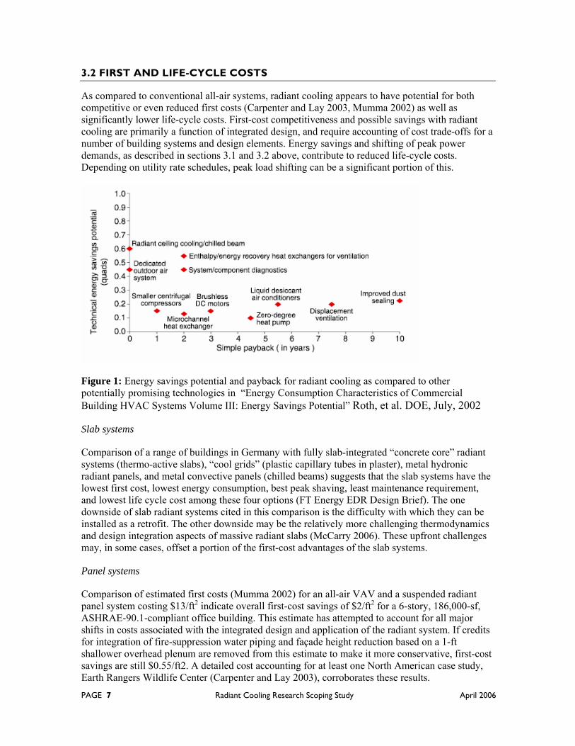
As compared to conventional all-air systems, radiant cooling appears to have potential for both competitive or even reduced first costs (Carpenter and Lay 2003, Mumma 2002) as well as significantly lower life-cycle costs. First-cost competitiveness and possible savings with radiant cooling are primarily a function of integrated design, and require accounting of cost trade-offs for a number of building systems and design elements. Energy savings and shifting of peak power demands, as described in sections 3.1 and 3.2 above, contribute to reduced life-cycle costs. Depending on utility rate schedules, peak load shifting can be a significant portion of this.
Figure 1: Energy savings potential and payback for radiant cooling as compared to other potentially promising technologies in “Energy Consumption Characteristics of Commercial Building HVAC Systems Volume III: Energy Savings Potential” Roth, et al. DOE, July, 2002
Slab systems
Comparison of a range of buildings in Germany with fully slab-integrated “concrete core” radiant systems (thermo-active slabs), “cool grids” (plastic capillary tubes in plaster), metal hydronic radiant panels, and metal convective panels (chilled beams) suggests that the slab systems have the lowest first cost, lowest energy consumption, best peak shaving, least maintenance requirement, and lowest life cycle cost among these four options (FT Energy EDR Design Brief). The one downside of slab radiant systems cited in this comparison is the difficulty with which they can be installed as a retrofit. The other downside may be the relatively more challenging thermodynamics and design integration aspects of massive radiant slabs (McCarry 2006). These upfront challenges may, in some cases, offset a portion of the first-cost advantages of the slab systems.
Panel systems
Comparison of estimated first costs (Mumma 2002) for an all-air VAV and a suspended radiant panel system costing $13/ft2 indicate overall first-cost savings of $2/ft2 for a 6-story, 186,000-sf, ASHRAE-90.1-compliant office building. This estimate has attempted to account for all major shifts in costs associated with the integrated design and application of the radiant system. If credits for integration of fire-suppression water piping and façade height reduction based on a 1-ft shallower overhead plenum are removed from this estimate to make it more conservative, first-cost savings are still $0.55/ft2. A detailed cost accounting for at least one North American case study, Earth Rangers Wildlife Center (Carpenter and Lay 2003), corroborates these results.

PAGE 8 Radiant Cooling Research Scoping Study April 2006
3.4 THERMAL COMFORT
Interior surface temperatures play a significant role in determining overall thermal comfort. While most evident for glazing and other perimeter surfaces, which tend to stray further from interior temperature set points, the same can be said of non-perimeter interior surfaces. Radiant cooling permits direct thermal control of active interior surfaces and, via radiant exchange between non-active and active surfaces, indirect control over or influence of the temperature of non-active surfaces. And, this combination of direct and indirect surface temperature control is almost entirely independent of ventilation supply air temperature.
All-air HVAC systems, on the other hand, address surface temperatures only indirectly, which tends to result in surface temperatures lagging behind the set-point temperature of conditioned air (warmer in cooling mode and cooler in heating mode). Because radiant cooling is typically part of a hybrid system that also includes conditioning of ventilation air, surface temperature control in radiant systems permits control over an added dimension of thermal comfort.
In contrast to an all-air system, non-perimeter surfaces in view of the active radiant absorber tend to be at or below the air temperature in cooling mode and at or above the air temperature in heating mode. Some research (Külpmann 1993) suggests that, for any particular resultant temperature, this relationship between surface and air temperatures may contribute to improved thermal comfort. Furthermore, conditioning of the building mass through radiant exchange with interior surfaces (plus direct coupling for hydronic slabs) provides improved thermal comfort for those who arrive before or stay after the operating hours of space conditioning systems (Stetiu 1999).
There is potential for improved thermal comfort related to decoupling means of addressing radiant sensible loads from those used to address latent and ventilation-air thermal conditioning loads. For example, when the conditioned space, especially perimeter space, is on the cool side—e.g., early in the day when building mass has yet to warm up—excessive or otherwise undesirable air movement might be more readily avoided as a function of both the smaller volume of air delivered to meet only ventilation requirements and the option for a system design that delivers ventilation air very near the room temperature set point.
Lastly, radiant cooling can be designed to provide local control of surface temperatures to balance perimeter gains and losses or other local conditions. Radiant cooling might thus more effectively balance radiant sources of discomfort, such as hot or cold interior surfaces of glazing.
3.5 INDOOR AIR QUALITY
Decoupling of primary space cooling loads and outside-air ventilation offers opportunities to improve indoor air quality. Potential benefits are related to minimizing or eliminating recirculation and synergies with certain airside systems. Eliminating recirculation provides relative air-quality benefits in proportion to the fraction of annual operating hours that a building in a given climate would not be able to use a 100% outside-air economizer for free cooling. The potential for reduced indoor air quality with smaller airside systems is further discussed in the section below on Indoor Air Quality in Moderate Climates. However, eliminating recirculation does not require a corresponding decrease in the ventilation system capacity for airside economizer operation. Rather, once the sensible load in the design has been shifted to the hydronic system, the extent of airside downsizing and the benefits associated with it should be weighed against the costs and benefits of economizer capacity for free cooling and air-quality benefits related to larger volumes of outside air.
PAGE 9 Radiant Cooling Research Scoping Study April 2006
4. POTENTIAL SYNERGIES
4.1 CHILLER OPERATION
Radiant cooling surfaces are typically operated at relatively warmer temperatures than the cooling coils in all-air systems. Cooling mode operating surface temperatures tend to be on the order of 56–59°F (13–15°C) for suspended panel systems (Simmonds 1996) and 63–68°F (17–20°C) for radiant slabs (McCarry 2003, Keller), with initial supply water temperatures ~1–3°F colder. These more moderate supply water temperatures reduce the temperature differential relative to the outside air where heat must be rejected. This permits more efficient chiller operation as compared to all-air systems requiring lower supply water temperatures around 44°F (7°C). In humid climates, however, more typical chilled water temperatures may still be required dehumidification. Given that many radiant cooling designs (particularly slab systems with high thermal inertia) require supply air to be delivered at no more than 1–4°F (0.6–2.2°C) below the air temperature in the conditioned space and are intentionally design not to allow for re-introduction of bypassed return air, a heat pipe, runaround coil, or exhaust-to-supply air heat exchanger may at least avoid the need for reheat.
4.2 NON-REFRIGERANT COOLING SOURCES
Radiant cooling designs operated with warmer-than-typical chilled water temperatures—e.g., 64°F (18°C)—enable the use of a broad range of low-energy cooling sources. This most often applies to slab-integrated systems, but is an option for panel systems where cooling loads are sufficiently moderate relative to available panel area. While the larger active surface area of slab systems facilitates the use of warmer water, it is also actually required by the slab’s thermal inertia (in all cases where the thermal mass of the slab is significant) to avoid overcooling following a rapid reduction in load. Waterside low-energy cooling sources include, among others:
Cooling towers and related fluid-air heat exchangers or coolers Indirect evaporative coolers Roof-spray evaporative cooling Stormwater retention ponds Night-sky radiant cooling Ground water Municipal water supply
Exceptionally moderate ventilation supply air temperatures suitable for certain designs—e.g., up to one degree below room air temperature (73–75°F or 23–24°C)—expand available hours for free cooling operation. Again, this applies mainly to slab systems, but not always. Even with an essentially neutral supply air temperature, the flow of unconditioned ventilation can remove a significant fraction of heat from people, lighting fixtures, and other convective sources, especially in the case of thermal stratification of the occupied space. However, this capability may be limited if airside systems are downsized with the shift of sensible space conditioning to a hydronic system.
The current state of the art, which is not widely understood or practiced in North America, uses an energy efficient building envelope to further expand opportunities for low-energy cooling sources. For example, an optimized building envelope with slab-integrated radiant cooling may be able to use natural ventilation and provide appropriate cooling with supply water no cooler than 68°F (20°C), thus expanding the useful capacity of an indirect evaporative source of chilled water.

PAGE 10 Radiant Cooling Research Scoping Study April 2006
4.3 OPTIMIZED AND/OR LOW-GRADE HEATING SOURCES
Large surface areas permit supply water temperatures around 86–104°F (30–40°C) for panel systems (Carpenter and Koklo 1988, McCarry 2003) and just 77–79°F (25–26°C) for radiant slabs (Zent-Fenger mbH). Not exceeding the latter is recommended for slabs (Keller) in order to avoid overshoot in heating mode as a result of thermal inertia if the heating load rapidly diminishes (e.g., when solar gain or internal heat sources increase over a short period of time). These moderate heating-mode supply water temperatures can facilitate either the use of relatively low-grade heat sources, such as solar-thermal collectors, or the optimized application of a condensing boiler. In the latter case, even an 86°F (30°C) inlet water temperature for radiant panel heating would maximize condensing mode operation.
While not a given, all types of hydronic systems can be designed to redistribute thermal energy when available, much as is done with a common-loop heat pump. For hydronic radiant slabs in buildings with moderate perimeter zone loads, continuous circulation of the cooling/heating supply water through the thermal mass can contribute to re-distribution of excess thermal energy from core zones. In the case of large core-load dominated buildings, recovered thermal energy from winter and shoulder-season mechanical cooling of core zones may be useful for heating in perimeter zones. Similarly, excess heat from perimeter zones with excess solar gain may be, at least partially, redistributed to zones in need of heat (McDonnell 2005)
The low-energy requirements for moderate to neutral supply air temperatures in ventilation-focused air systems may permit extended reliance on energy recovery devices as a principle means of ventilation air conditioning. Furthermore, the reduced need for relatively high air temperatures in heating mode would tend to expand the climatic application of transpired solar collectors (typically perforated metal) designed to directly heat ventilation air as it is drawn into the building.
4.4 NATURAL VENTILATION AND MIXED-MODE DESIGNS
The season or climate for effective natural ventilation may be extended in some cases by using radiant systems to supplement passive design and natural ventilation and cooling. Both radiant panels and slabs may be applicable for mixed-mode designs using a seasonal changeover control strategy, but this provides little advantage in terms of extending the season or climate for the natural ventilation. Rather, opportunities for extending natural ventilation tend to be in the context of either zoned or concurrent mixed-mode control strategies.
Radiant panels, which have more rapid response times and tend to allow for added compartmentalization of local space conditioning, may be better suited to zoned mixed-mode applications, particularly in humid climates. For example, a zoned mixed-mode system could control panel groups according to outdoor conditions and the status of operable windows.
Slab systems, on the other hand, tend to operate at much more moderate surface temperatures. Direct coupling to thermal mass also provides expanded opportunities for precooling. So, while they may be inappropriate for a fast-acting zoned control strategies, they can be paired with natural ventilation in a broader range of climates without concern for condensation. Thus radiant slabs tend to be better suited to designs with concurrent space conditioning by natural ventilation. One possible exception to this is hot, dry climates, where panels may be equally applicable in terms of avoiding condensation, but will have both advantages and disadvantages related to cooling capacity and potential for use of low-energy cooling sources.

PAGE 11 Radiant Cooling Research Scoping Study April 2006
4.5 UNDERFLOOR AIR DISTRIBUTION (UFAD)
Thermal decay may be reduced in UFAD systems by removing thermal energy directly from floor slabs (in the case of slab-integrated radiant systems), and via radiant exchange from raised floor surfaces, overhead surfaces, and lighting fixtures that normally contribute to heating the underfloor plenum. While this potential for reduction in thermal decay has yet to be documented, the phenomena of thermal decay in UFAD plenums has been the subject of recent CBE research (Bauman et al. 2006, Jin et al. 2006). Reducing thermal decay provides designers with greater assurance that diffuser discharge air temperatures will not be excessively high, and may allow greater freedom in configuring underfloor plenums (e.g., larger zones). Active slab control in UFAD systems may also provide an opportunity for nighttime precooling of the slab without overcooling the occupied space, more often a problem for morning warm-up in airside precooling strategies.
Moderate ventilation supply air temperatures in the range of 64–75°F (18–24°C) permitted or even required by some radiant cooling design and control strategies (Keller, Olesen 2000) may also reduce sensitivity to thermal decay. This is because thermal decay in UFAD plenums is both a function of residence time in the plenum and the ∆T between supply air and the surfaces of the floor slab and underside of the raised floor panels. However, not all designs permit such moderate SA temperatures and some depend on the added airside cooling capacity derived from delivering supply air as cold as is feasible without detracting from occupant comfort near diffusers (Mumma 2001).
There may also be synergies with UFAD systems in terms of contributing to improved ventilation effectiveness and indoor air quality. As a result of thermal stratification, all-air UFAD systems are generally believed to at least offer potential for improved ventilation effectiveness, and thus some improvement of indoor air quality, even in designs with recirculation. To the extent that diffuser selection, air velocities, and thermal stratification are successful in maintaining mixed air only in the lower occupied zone, pollutants tend to be transported to the warmer, stratified layers of the unoccupied zone above, which are then gradually displaced by the addition of air to the occupied zone. While these systems are most often designed with swirl diffusers and other terminal devices that tend to mix air within the occupied zone, some UFAD systems are designed and operated as true displacement ventilation (DV). Where appropriately applied and when in cooling mode, this may contribute to further improvements in ventilation effectiveness.
With reference to just the UFAD systems itself, the principal difference in DV vs. non-DV strategies are the type and number of diffusers and the airflow rate at each diffuser. When radiant cooling is used, the reduced airflow and associated requirement that ventilation air is introduced at temperatures consistently below that of the occupied space suggests a DV design strategy for UFAD. Regardless of the specific UFAD strategy, for a fixed number of diffusers a reduced airflow rate will tend to increase thermal stratification and decrease mixing in the occupied zone, thus pushing the operation of UFAD towards the DV end of the spectrum (Bauman, F. 2003). Caution should be exercised, however, as excessive thermal stratification may compromise occupant comfort.
4.6 DISPLACEMENT VENTILATION
The potential for separating sensible space conditioning and ventilation with hydronic radiant systems allows designers to employ a dedicated 100%-outside-air ventilation system (DOAS). By minimizing mixing with air already in a conditioned space, displacement ventilation (DV) has the potential to deliver the indoor air-quality benefits of DOAS to occupants.

PAGE 12 Radiant Cooling Research Scoping Study April 2006
Radiant cooling can be used to extend the applicability of DV, which has a low cooling capacity relative to other all-air systems (Carpenter and Koklo 1988). For example, DV alone may be insufficient for many perimeter applications where loads would tend to exceed the practical limits of cooling capacity, airflow volume, diffuser area, and thermal gradient within the occupied zone. In many such cases a radiant system would be an appropriate means of providing the added sensible cooling required.
It is widely accepted that DV is inappropriate means of providing heat. Warm air introduced at very low velocities, particularly in the case of large wall-mounted diffusers, tends to rise up to the ceiling where it flows to return grills before reaching occupants or mixing with room air. Radiant systems provide a source of heating that is generally compatible with DV. In heating mode, fresh air delivered by the DV system very slightly below the space temperature will facilitate even distribution and the intended thermal stratification of the space.
Radiant cooling of the floor slab also has potential synergies with DV in high-ceiling spaces, such as airport terminals (Simmonds et al. 2000, Simmonds et al. 2006). DV is well suited to this type of space because it can be used to thermally stratify the space, creating an appropriately conditioned occupied zone near the floor while allowing a potentially vast upper portion of the space to “float” at a much higher temperature. Addressing some fraction of the sensible load via a radiant floor slab, various forms of suspended and wall-mounted panels, or even an active surface relatively high above the occupied zone will tend to complement a DV solution. As with the DV system, thermal comfort is provided without conditioning the entire space volume.
4.7 AIR FILTRATION AND THERMAL ENERGY RECOVER
Shifting sensible cooling loads to hydronic radiant surfaces permits designs using airside systems sized primarily for ventilation. Because all-air systems typically circulate between two-and-one-half and five times as much air for cooling purposes as is required for ventilation, hydronic radiant cooling can reduce airflow 60–80% as compared to an all-air system. The fan energy required to move all supply air through filtration and/or energy recover devices is thus also reduced. This facilitates the use of finer filtration media for improved indoor air quality. Likewise, the viable application of enthalpy wheels or other types of energy recovery ventilators is expanded.
4.8 DUCTWORK AND DAYLIGHTING
The 50–80% range of likely airflow reductions with hydronic radiant cooling, depending on the particular climate and design—e.g., degree of airside space conditioning, types of airside terminal units, value of airside economizer capacity, etc.—allows for a corresponding downsizing of ductwork. Where UFAD or DV systems are used, overhead ductwork can be more or less eliminated from occupied spaces (Bauman 2003). Even when using a more conventional overhead air system, downsizing of ducts to handle mainly ventilation requirements could free up space.2 Where suspended radiant panels or chilled floor slabs are used in conjunction with overhead air distribution and a T-bar drop ceiling, the reduced size of ducts may permit a smaller overhead return plenum. In either case, expansion of floor-to-ceiling height for a given floor-to-floor height could potentially allow for higher clerestory fenestration and thus deeper penetration of daylight. If the drop ceiling were eliminated, smaller or minimized ductwork in the overhead space would provide similar advantages for daylighting.
2 Alternatively, larger ducts (in the context of hydronic space conditioning) could be specified as a means of reducing energy consumption related to duct static pressure.

PAGE 13 Radiant Cooling Research Scoping Study April 2006
Alternatively, a reduction or elimination of space dedicated to overhead ductwork might, for some designs, facilitate reduced deck-to-deck heights. This could offer first-cost savings, particularly in taller multi-story buildings. Downsizing ductwork, however, should be thoughtfully balanced with other benefits of maintaining larger duct capacities, such as reduced fan energy and maintenance of airside economizer capacity.
4.9 FAÇADE OPTIMIZATION
Downsizing of ductwork and, in some cases elimination of ceiling plenums, permits either reduced deck-to-deck façade height, saving materials and construction, or taller glazing units that may contribute to improved daylighting.
5. CHALLENGES, CONSIDERATIONS, AND PERFORMANCE TRADEOFFS
5.1 CLIMATE AND COOLING CAPACITY
Depending on design and operation, radiant cooling may be applicable to the full range of climates in North America. Humidity and solar gain play significant roles in this determination.
For all types of radiant cooling, applications are constrained according to climate to the extent that humidity limits surface temperatures. As a general rule, the surface temperature must not equal or drop below the space dew-point temperature. There is, however, evidence that suggests dropping below the dew-point temperature for a limited period of time may not cause sufficient condensation for droplet formation (Mumma 2002). Questions remain about the range of conditions for which this would be true. On the other hand, with available control options, condensation appears only to be a significant limitation in cases of operable windows, other natural ventilation, or the absence of adequate dehumidification. The Humidity section below discusses this further.
If humidity can be addressed, application within all climates across North America may be feasible, provided building skin and internal loads do not exceed the capacity of radiant systems. Humidity aside, cooling capacity is constrained by different factors for slabs vs. panels.
Slab systems
Sensible cooling capacity for typical slab-to-space temperature differentials is on the order of 24 Btu/hr-ft2 (~7 W/ft2 or 77 W/m2) of active surface, not including associated ventilation systems or strategies. When even a relatively low-cooling-capacity ventilation system, such as DV, is also accounted for, cooling capacities begin to approach those of conventional all-air VAV systems. Although not yet well understood (McCarry 2006), thermal mass in conjunction with various precooling strategies may add to useful cooling capacity (see bar graph in § 2.0).
Because of their thermal mass and associated thermal inertia, capacity for slab systems is constrained by the need to avoid either over cooling or overheating a space with a change in loads. One strategy that is helpful in maximizing the usable capacity of slab systems is to minimize variations in load. While this is relatively feasible with regard to the building envelope, internal loads associated with normal variations in occupancy, lighting, use of equipment, and so forth are not something the designer can control. Thus the capacity is still constrained by the need to maintain slab surface temperatures within the range desired for human thermal comfort—typically 64°F (18°C) minimum in cooling mode, and 75°F (24°C) in heating mode.

PAGE 14 Radiant Cooling Research Scoping Study April 2006
While residential radiant floor slab heating systems are often operated at surface temperatures outside of this range—e.g., up to 85°F (29°C) or more, the approach discussed here for radiant slabs in commercial buildings seeks to avoid the overshoot that might be caused by this if the thermal load were to be reduced more quickly than the slab could respond. (This is actually a relatively common problem with radiant slab heating in passive solar homes, wherein the slab that was the sole source of heat in the very early morning continues adding heat to the space later in the morning when the winter sun first begins significantly adding heat as well.)
At 64°F (18°C) the cooling capacity of a radiant slab is approximately 24 BTU/hr/ft2 (76 W/m2) (Mikler 1999). For those who prefer to think of internal loads in mixed units, this is approximately 7 W/ft2. Typical internal sensible loads for office spaces can easily be 3–4 W/ft2, including lights (1.0–1.8 W/ft2), equipment (1.5 W/ft2), and people (0.4–0.8 W/ft2 sensible fraction). This leaves relatively little room for skin loads, suggesting that the use of radiant slabs as the primary source of cooling might actually require a high-performance building envelope.
A look at sensible cooling loads for average interior spaces suggests that buildings designed for existing energy codes are already within range. For example, non-ventilation peak sensible cooling loads for the average of all spaces in a Title-24-compliant Los Angeles, CA 2-story office building would be in the range of 4–5 W/ft2 (and similar for a building designed to ASHRAE standard 90.1). However, the key to applicability of radiant slab cooling would tend to be reduction of non-ventilation peak sensible perimeter loads, which could be on the order of 10 W/ft2 in the very same Title-24-compliant building. Improving the building envelope to reduce peak perimeter loads will also reduce the variations in loads discussed above as presenting potential challenges for radiant cooling slabs with significant thermal mass. On the other hand, the mass will also tend to buffer some (mainly slower) load fluctuations to some degree, thereby at least partially offsetting limitations related to response time.
Panel systems
At roughly 30 Btu/hr-ft2 (~9 W/ft2 or 95 W/m2) active surface, not including associated ventilation systems or strategies, the sensible cooling capacity of hydronic radiant panels generally greater than that of slabs. However, that added capacity is provided by lower surface temperatures, and thus may rely to a greater degree on dehumidification. Capacity will also be constrained by cost, which is considerably higher per unit active surface area than for hydronic slabs.
Increased convective cooling tends to improve effective cooling capacity through added air movement—as achieved in typical mixing systems, passively via louvered “chilled beams,” or even high-velocity nozzle type diffusers directing airflow along panel surfaces. According to Penn State University research with panel systems, capacity may be increased as much as 30% with a panel surface of 59°F (15°C) with an adjacent diffuser exit velocity of 6 m/s (Jeong and Mumma, 2003). However, by increasing the convective cooling component, this approach may negate some of the benefits of radiant cooling systems.
5.2 ADDRESSING DIURNAL SWINGS AND VARIABILITY OF SOLAR GAINS
Within the limits of cooling capacity for the radiant surface temperature, changes in load are handled by corresponding changes in radiant exchange governed by the fundamental physics of radiant systems. When a non-active surface is warmed by solar gain or new source of heat is added to the occupied space, the rate of exchange with available chilled surfaces increases in keeping with the temperature differential. However, when the added load exceeds the cooling capacity of the available chilled surface and current supply water temperature, response time becomes a factor.
PAGE 15 Radiant Cooling Research Scoping Study April 2006
Slab systems
For radiant slabs, variability of solar gains should be addressed by building envelope design, materials, and technologies. Radiant slabs are generally too slow to react to rapid changes in load, such as a sharp rise in solar gain when clouds disperse. Even when there is capacity in the slab to absorb the added load, the rate of heat penetration in massive materials such as concrete tends to be quite slow—on the order of one–two hours per inch (25 mm) of thickness for the typical range of slab/space temperature differentials. This thermal lag has distinct advantages for nighttime pre-cooling strategies and riding out moderate midday increases in solar load, but is not well suited to reacting to rapid changes in load.
Conditioned ventilation air, fan-coil units, and added lightweight hydronic radiant cooling panels can be used to address fluctuations in load beyond the base load addressed by the active slab. However, these solutions tend to diminish benefits associated with radiant cooling slabs. Therefore, it tends to makes more sense to focus first on minimizing transient loads. Added attention to improving the building envelope may also minimize radiant asymmetry in perimeter zones—a potential source of local discomfort, even when the mean radiant temperature appears satisfactory.
To some extent, differences between spaces—e.g., an east-facing perimeter zone heated by the morning sun vs. a cooler zone facing north—can be reduced by a strategy of constant water circulation. Thermal energy is thus redistributed from a warmer zone to a cooler zone in much the same manner as a common-loop heat pump. The same strategy can be applied to buffering significant variations in internal loads. Basically, the thermal mass in the cooler zones acts as a sink for the excess heat in the warmer zones. This is similar, in principal, to using a common-loop heat pump to redistribute thermal energy among zones. Because of the mass involved, however, there is some thermal lag built into this approach.
If insufficiently minimized by the building envelope, supplementary systems can address local or zone-specific variable loads. These include VAV control of conditioned ventilation air, fan-coil units, induction units, chilled-beam convectors and diffusers, and added radiant panels, each of which has a faster response time than the radiant slab, but has costs that must be absorbed. Several of these options would require significantly larger air system capacity than required for minimum ventilation.
Panel systems
Because they are not thermally massive, panel systems can react very quickly, and thus are flexible with respect to handling variations in loads or the differences among zones that might results from solar orientation, etc. However, this is still limited by cooling capacity. In the case of panels, capacity is constrained by available space, relatively high cost per unit area of the panels, and the minimum temperature of the panel surfaces in keeping with available dehumidification.
5.3 HUMIDITY
Because thermal inertia in a slab could easily override a dehumidification or supply-water temperature control failure, most designs for slab-integrated radiant cooling tend to avoid the potential for condensation altogether. Most often this is achieved through cooling surface temperatures held above even the outdoor dew-point temperature (DPT) (Olesen 2000).
Where outdoor DPT can run right up against and even above desired indoor temperatures, radiant slabs tend to be used as part of a hybrid system. For example, the Callaway Discovery Center, Pine Mountain, GA is a 34,000-SF visitors center and educational facility with highly variable
PAGE 16 Radiant Cooling Research Scoping Study April 2006
occupancy. The mid-summer average DPT for Pine Mountain, GA is 73°F (22°C) with a maximum DPT of 79°F (26 °C). Open public and circulation areas of the building have radiant heated and cooled floor slabs, plus conditioned ventilation air. Closed spaces use a more conventional VAV system. Heated and chilled water is provided by a water-source heat pump using the adjacent lake as a heat source and sink. According to Flack+Kurtz, designers of the system, environmental controls have achieved desired comfort levels and there has been no indication of floor condensation.
For some radiant slab designs dehumidification is essential. For example, Bangkok Airport, Thailand (Simmonds et al. 2006) uses constant 66°F (19°C) floor slab surface temperature to remove direct gain from short-wave solar radiation and 24-hour/day airside dehumidification. Moisture detection is provided at slab headers as a back-up in case of a building management system failure.
Lightweight panel systems, on the other hand, are more often designed to operate at the temperature of the coldest available chilled water in order to maximize cooling capacity with limited surface area. Chilled surfaces may frequently operate well below the space DPT. While failure of dehumidification is almost certain to occur at some point in time, research at Penn State University suggests that the resulting condensation may not present a significant risk. Testing of condensation on a horizontal chilled surface after 8.5 hours at 14°F (7.8°C) below the space DPT (Mumma 2002) was not enough to cause a single drop to fall.
This research should also be considered in the broader context of various real-world applications, including panels with irregular edges, louvered chilled beams, surfaces with more textural irregularity (e.g., a poured concrete slab), or non-horizontal surfaces (e.g., downturn beams or convoluted waffle surfaces). It is not clear that droplets would not at least begin to fall much more readily in one of these situations. However, there appears to be little other research on this topic.
Fortunately, for the inevitable failure or unanticipated situation, there is one more possible line of defense: a water sensor (also tested at Penn State University) comprising an element that swells when moistened, a normally closed switch, and a normally closed, spring-return control valve for each hydronic loop or panel group. The swelling element is located on most nearly vertical element of the inlet to the first panel or slab in a series (the location that will receive the chilled water first, and thus be the first place condensation would occur). The swelling in the presence of water allows the normally open switch to open, thus breaking the current to the normally open spring-return valve. The spring-return valve then closes, cutting off the flow of chilled water. (Mumma 2002)
Operable windows
With operable windows, natural ventilation, high levels of infiltration, or other situations lacking dehumidification, surface temperatures must not equal or drop below the space dew-point temperature. For example, with operable windows or natural ventilation, many North American climates will require chilled surface temperatures no less than about 64°F (18°C) to avoid condensation. This limits cooling capacity as described above in the Climate section.
Entryways
For building with operable windows or natural ventilation, entryways are clearly a non-issue, or at least no more of an issue than the operable windows. Where the building is otherwise sealed and outdoor conditions are likely to cause condensation on radiant surfaces, entryways are often separately conditioned using a fan-coil unit or other non-radiant terminal device.

PAGE 17 Radiant Cooling Research Scoping Study April 2006
5.4 INTERFERENCE WITH DV OR UFAD THERMAL STRATIFICATION
Low-temperature surfaces near the top of a space can potentially interfere with desirable thermal stratification and buoyancy in DV and UFAD applications. However, assuming chilled surfaces are horizontal and continuous (i.e., not vertical, suspended, or louvered, etc.) stratification and buoyancy are not significantly affected until the chilled surface temperature is sufficiently low relative to the occupied space—for example, 60°F or lower with 75°F typical occupied space temperature (Mikler 2006). Thus, while typical operating temperatures on the order of 55°F for suspended panel systems and chilled beams might be incompatible with stratified environments, the considerably warmer operating temperatures of overhead slab systems are less likely to interfere with stratification. Even with slab systems, however, a convoluted form with down-turn beams or similar non-horizontal surfaces may increase the potential for interference with stratification.
5.5 AIR MOVEMENT AND VENTILATION-ONLY AIRFLOW
Downsizing airside systems and ducts to focus on delivering only the required volume of conditioned outside air is among the more attractive potential benefits of radiant cooling. Given this, it may be all too easy to design a system with insufficient air movement for optimal thermal comfort in a hot and/or humid climate. In some cases it may therefore be necessary to increase the ventilation air volume or velocity at the diffusers. Alternatively, ceiling fans or similar means of introducing air movement might effectively augment such designs.
If not handled appropriately, the reduction in airflow rate and quantity from diffusers may also present challenges related to getting ventilation air to the breathing zone. While conventional all-air overhead systems tend to have more than adequate airflow to provide mixing of ventilation air into the breathing zone, airflow at the diffuser for overhead ventilation with radiant cooling may be inadequate for complete mixing. Conveyance of ventilation air to the breathing zone is thus more likely to be driven by differences in buoyancy. Ventilation air from a mechanical DOAS or other source, including ducted natural ventilation, should therefore preferably be delivered at a temperature slightly below that of the occupied space, even in heating mode, to ensure that fresh air will descend into occupied zone (OH system) or stay in the occupied zone (UFAD & DV) until heated by occupants, other thermal gains, or mixing (Mikler 2006). When in heating mode, radiant systems sized for cooling loads generally have more than adequate capacity to offset added space load associated with introducing cooler ventilation air.
That said, consideration should be given to how this approach to SA temperature would succeed in situations where loads vary among spaces on a common thermostat and hydronic loop. This may be of particular concern where the radiant system is a slab with significant thermal inertia, and thus more likely to require at least transient airside tuning of space temperatures. The radiant system may need to be operated to satisfy the space with the least need for cooling so that control of ventilation air introduced at a temperature below the target space temperature can be used to tune thermal comfort according to differences in solar gain, internal loads, etc. among all other spaces on the same loop. Another possible solution is to include low-mass suspended radiant panels in spaces such as conference rooms and corner offices that are expected to have intermittent cooling loads exceeding those in other spaces on the loop. If the intermittent heating loads are anticipated, these added panels would need either to be on a four-pipe hydronic system or be electric rather than hydronic.

PAGE 18 Radiant Cooling Research Scoping Study April 2006
In the case of radiant panels, where maximizing effective cooling capacity for relatively more expensive active surfaces is often a primary design objective, increased air movement may be desirable (see §5.1 Climate and cooling capacity). However, this will tend to drive the design towards greater dependence on maintaining higher airflow velocities, and thus greater reliance on airside systems. If airside systems are also to be downsized as allowed by the hydronic system, supply air temperatures will then tend toward the low end of the spectrum. While beneficial in terms of maintaining a low space dew-point temperature, this approach is generally compatible only with mixing overhead air distribution (i.e., not UFAD or DV), and thus may not fully capture the potential indoor air quality benefits of non-recirculating dedicated outside air systems.
5.6 INDOOR AIR QUALITY IN MODERATE CLIMATES
Replacing a typical all-air system with radiant cooling and a much smaller air system focused on ventilation and latent loads can affect indoor air quality (IAQ) both positively and negatively, depending on the climate. In moderate climates where ambient temperatures range between approximately 55°F and 65°F (13–18°C) during a significant fraction of annual building operating hours, choosing radiant cooling and a much smaller air system focused on ventilation and latent loads may bring about a net IAQ reduction, at least for those hours of operation. This is because a conventional all-air system in a moderate climate can use an economizer to take advantage of 100% outside-air (OA) free cooling whenever ambient conditions are favorable.
Downsizing the air system in a case such as this would reduce the amount of outside air that could be drawn into the building during economizer operation. (The impact of this can be far less in buildings where operable windows or mixed-mode natural/mechanical ventilation systems provide alternative means of getting additional outside air into the building.) Furthermore, the moderate 61–65°F (16–18°C) cooling supply air temperatures required in UFAD systems tends to expand the number of hours available for 100%-OA economizer operation in a given climate, effectively expanding the potential for undesirable reduction in IAQ with a smaller air system. Thus the reduction of air system capacity in a moderate climate may, depending significantly on the particular climate, partially or wholly offset IAQ improvements associated with radiant cooling plus a dedicated 100%-OA ventilation-only air system.
For climates where this is a relevant concern, mitigating it in the context of radiant cooling would necessitate a larger air system than needed to meet minimum ventilation air requirements. This strategy for optimizing IAQ in moderate climates gives up some potential first-cost and interior-space savings related to downsizing equipment and ducts. If airflow is reduced during non-economizer hours, an increase in part-load fan operation may also slightly increase energy consumption. However, these losses may in turn be offset by significantly reduced pressure drop in a duct system sized for larger air volumes. At a given load fraction—e.g., 50% of full capacity—and using current motor technology, typical fan energy savings from reduced pressure drop (depending on duct layout and design) tend to far outweigh fan energy losses resulting from part-load operation of the fan, motor, and drive.
To avoid far more significant additional losses from part-load chiller operation, the chiller would need to be sized according to the cooling load corresponding to the maximum airflow anticipated during non-economizer operation. That said, a moderate cooling climate that makes this relevant would also tend to enable the use of non-refrigerative cooling sources, many of which are much less prone to part-load losses.

PAGE 19 Radiant Cooling Research Scoping Study April 2006
5.7 ACOUSTICS
Like UFAD, both major types of radiant cooling systems come with a combination of benefits and challenges related to reducing the background noise associated with all-air HVAC systems. With the typical 60–80% reduction in airflow, substantial reduction in fan, duct, and diffuser noise is probably inevitable. Reduction of background noise may enhance indoor environmental quality for individuals and facilitate verbal communication. However, it also tends to reduce masking of other distracting noises and conversations, particularly in open-plan office configurations.
Slab systems
While radiant slabs generally have the advantage of greater active surface area per unit cost, keeping this surface appropriately exposed can contribute to acoustic challenges. Even with sound damping drop ceilings, open-plan office spaces often face challenges of acoustic privacy. Reducing the background noise associated with all-air HVAC systems and removing the drop ceiling to expose an overhead concrete slab would appear to exacerbate the challenges at hand.
Some designers have reported, however, that in spaces with both carpeting and cubical type furniture systems, this has not been a significant problem (McDonell 2005). Others have suggested that partially covering the overhead slab with an appropriate arrangement of surface-mounted acoustic damping material does not significantly impair cooling capacity, as the mass covered by the acoustic materials still contributes to removing heat from the exposed portions (McGinn 2005). Furthermore, with some overhead slab designs there may be opportunity to place acoustic materials on the vertical surfaces of integrated structural beams. The vertical orientation of these surfaces that makes them less desirable for radiant cooling does not appear to detract from their capacity for absorbing sound (McGinn 2005). A suspended “cloud” of acoustical panels can also be hung below the ceiling where it has a reduced impact on cooling capacity. However, given the relatively low cooling capacity per unit area of slab systems, any acoustic treatment that obscures even part of the surface will tend to be better suited to core zones where perimeter loads are more or less absent (McCarry 2006). Alternatively, a sinusoidal or other non-planar ceiling surface, such as provided in the San Francisco Federal building by EHDD Architects now under construction, may improve acoustics, at least for some individuals in the space.
Panel systems
Where panels are suspended in a T-bar drop ceiling, they are often made from perforated metal and have acoustic damping material placed on top of them. Many pendant-mount panel systems, however, may not include acoustic damping. In this case acoustic materials could be mounted on the ceiling above without significantly affecting cooling performance.3 Some perforated suspended metal panels also have desirable acoustic damping properties similar to acoustic ceiling tile in the range of 125–4,000 Hz (Conroy and Mumma 2001). With regard to acoustical challenges, panel systems might be preferable in applications that include hard floors.
3 When using this approach, there may be a reduction in potentially desirable radiant exchange with the mass of the floor deck above.

PAGE 20 Radiant Cooling Research Scoping Study April 2006
5.8 CONSTRUCTION, ACCESS, AND MODIFICATION
Slab systems
Modern radiant slab technology embeds flexible polymer tubing within the concrete. The tubing is usually tied to the reinforcing metal prior to pouring of the slab. Thoughtful designers also include a grid of metal inserts to facilitate hanging items from the ceiling without having to drill holes. The polymer tubing is robust, flexible, and can accommodate numerous zones with a minimal number of connections. Once the slab is poured, the configuration of zones is fixed.
Panel systems
Whether hung from pendant mounts or suspended on T-bar within a drop ceiling, installation of panels is more or less akin to installation of similarly suspended lighting fixtures. While panel systems are generally much more plumbing-intensive, this adds a degree of flexibility. Furthermore, all plumbing and connections are usually readily accessible for reconfiguration, modification, or repair. The relatively complex mounting hardware sometimes included to facilitate access can, however, add to cost.
5.9 POTENTIAL FOR LEAKS
Historically there have been problems with leaks from certain types of metal pipe that were prone to corrosion as a result of contact with sulfates in concrete, stray electrical currents, or contact with dissimilar metals. Some early plastic tubing also had problems associated with oxygen diffusion into the circulating water, which could then contribute to corrosion of the metal fittings and other components to which the tubing was attached. However, current building codes, materials, and technologies appear to have addressed those problems. The Uniform Mechanical Code, for example, requires that all tubing embedded in slabs be continuous—i.e., with no joints whatsoever—thus minimizing the potential for a leak within a slab. Furthermore, PEX, or cross-linked high-density polyethylene tubing, has thus far earned a reputation for robust performance in both residential radiant heating applications and in European commercial buildings (Rea et al. 2001). With accelerated testing predictions of a 100-200-year life for PEX, and other claimed benefits over copper pipe, PEX is now provided by major suppliers for a broad range of residential and commercial plumbing applications outside of radiant heating and cooling (Zurn).
It is essential to avoid embedded tubing being punctured when installing an anchor in the slab. This is generally handled by first including regularly spaced anchors in the slab at the time of construction, and then by using an infrared camera to determine the location of the embedded tubing if a hole must be drilled.

PAGE 21 Radiant Cooling Research Scoping Study April 2006
6. FUTURE RADIANT COOLING RESEARCH AT CBE
6.1 RESEARCH NEEDS AND UNANSWERED QUESTIONS
The following are research needs and questions raised by CBE, our industry partners, or a combination thereof. They are collectively based on a combination of literature review, interviews, and other CBE research. They were also informed by a meeting that CBE held in Vancouver, BC with representatives from Stantec (formerly Keen Engineering), Omicron, and Cobalt Engineering, specifically aimed at including the perspective of those currently designing radiant systems. These needs and questions fall into two categories: 1) those that remain largely underserved or unanswered by the literature and related industry resources that CBE has thus far reviewed; 2) those intended to frame more specific inquiries that might address needs implied by the first category.
Broader needs and questions
According to several CBE industry partners and other designers interviewed, education appears to be critical to the adoption, where appropriate, and then to the successful design and implementation of radiant cooling. Education appears to play a particularly critical role where experience with radiant cooling is lacking or limited. The target audience includes building owners, architects, engineers, and facility managers and operators. Given that ASHRAE Handbook series provides reasonable coverage of radiant panel design fundamentals and numerous technical papers have been published on particular designs or design strategies, what tools, products, or processes might best serve the need for further education?
Within the context of the previous question, CBE partners and others have suggested a need for engineering education emphasizing reduction of loads as a precursor to the adoption of radiant cooling (and/or related or similar low-energy cooling systems). This is in contrast to the current engineering emphasis in North America on mechanical systems and the degree to which the optimized low-energy design of the building itself is therefore overlooked. It is considered particularly important in the context of active hydronic slab systems, as the viability of these systems and the capture of their benefits appears closely linked to space loads reduction. What tools, products, or processes might best either support a shift in this balance or support those seeking to optimize the low-energy design of buildings? Should this fall within the scope of CBE work on radiant cooling specifically, or does it suggest a need for an expanded CBE role in education and tools related effectively optimizing buildings for reduced loads?
Within the context of the two previous statements of needs and associated questions, CBE partners and others have suggested there is currently a lack of design guidance beyond engineering fundamentals. Our literature review, interviews, and discussions indicate that there is a range of guidance and examples available beyond the fundamentals, but that these are generally either specific to a particular strategy or climate or are insufficiently based upon documentation of actual performance. This suggests interrelated overarching needs for:
1. An expanded pool of rigorous data regarding the actual performance of radiant cooling systems in North American buildings and climates, including evaluation of both system performance and occupant comfort;
2. More comprehensive assessment of radiant cooling with respect to design strategies, applications, climates, thermal and energy performance, acoustics,
PAGE 22 Radiant Cooling Research Scoping Study April 2006
financial considerations, and interactions with both building design optimization and other building systems;
3. Design guidance that is both more comprehensive and better grounded in field studies of actual radiant systems.
Specific questions and needs suggesting or framing future inquiry
According to CBE partners and other system designers, there is need for more accessible and better-integrated tools for understanding and optimizing glazing, façade performance, thermal bridging, and so forth as the precursor to application of radiant cooling. While TAS, Virtual Environment, TRNSYS, and EnergyPlus, for example, all have appropriate capabilities, the learning curve and per-project investment of time required by these tools makes it difficult for average design engineers to make practical use of them on most projects. Furthermore, in some North American markets, including Canada, for example, those with the required skills and appropriate knowledge for use of these tools are in high demand and short supply. What then might appropriately accessible and integrated tools for average engineers look like and how might CBE contribute to their development? Should CBE somehow also contribute to the broader evaluation and awareness of TAS, Virtual Environment, TRNSYS, and EnergyPlus such that they might be better understood by educators as potential design tools?
If, in certain cases, radiant slabs in buildings with exceptionally energy efficient envelopes do provide the combined benefits of improved performance and reduced first cost, what are the factors that need to be present for this outcome to be realized? Are there thresholds related to climate, building type, building scale, etc., below or beyond which this solution set is no longer viable or cost-competitive? Are there circumstances for which this combination of improved performance and reduced first cost is also available with hydronic radiant panel systems?
To what extent are energy savings achievable with radiant cooling across all major climate zones in North America? What are the constraining factors and thresholds? What are the target systems parameters and technological options best suited to these various climates?
What is the true impact of radiant cooling surfaces on thermal comfort? How might we learn more about this through a combination of analytical modeling, field measurements, and post-occupancy evaluations for buildings with and without radiant cooling?
How effective is radiant cooling in compensating for asymmetrical radiant environments? How might an improved understanding of this be made useful for designers in the field?
To what extent is acoustic performance actually a more significant issue for radiant cooling than for more conventional systems? What might constitute viable solutions, particularly in the case of systems using exposed radiant slabs rather than suspended panels? Are there appropriate examples of these solutions that could be used to verify performance via field measurements?
Given the range of enabling functions of radiant cooling for natural ventilation—i.e., in mixed-mode buildings—what are the corresponding limitations and boundaries across a range of climate zones?
To what extent are there synergies between radiant cooling and UFAD systems, and what benefits might these synergies offer? Are there measurable first-cost or life-cycle financial benefits? If so, under what circumstances are these benefits likely to be available or not? Can

PAGE 23 Radiant Cooling Research Scoping Study April 2006
radiant cooling effectively address thermal decay in UFAD systems? Are there applications where this combination would either be technically undesirable or more costly on a life-cycle basis than UFAD in conjunction with more conventional HVAC technologies? Under what circumstances is a non-UFAD displacement ventilation system likely to be more suitable in combination with radiant cooling?
What might constitute an optimized integration of radiant cooling and UFAD? Can the combined and synergistic benefits of these systems be more or less optimized by means that account for both quantitative cost and benefits and qualitative aspects, such as indoor environmental quality? What practical tools might most effectively assist designers in answering these questions for a given project?
Prevention or minimization of the possibility for condensation has been demonstrated through various approaches to design and/or controls, and this has been recorded in the literature. Given these relatively recent developments, is there sufficient evidence to support clear and rigorous conclusions and to dispel concerns related to historical problems with condensation? Is the range of illustrative projects yet large enough to be truly convincing and broadly applicable across the range of climate zones in North America? Have these projects been in operation long enough to establish a suitable track record of condensation-free performance?
According to CBE partners and others, the adoption of radiant cooling is hampered by a perceived lack of legitimacy as a viable option. Is there an appropriate role for CBE research in providing unbiased support to programs that might counter this, such as those carried out by utilities in Canada to improve recognition of ground-source heat pumps as an option?
Design engineers see capillary tube radiant cooling products as a desirable option for certain plaster-in-place and suspended panel applications. However, there lack of availability in the North American domestic market and the relatively high cost of imports precludes there use in many cases. Is there a role that CBE might play in evaluating the effectiveness of such products, and thus raising awareness of their attributes among North American HVAC equipment suppliers?
According to design engineers at Omicron and Cobalt Engineering, overall costs and cost trade-offs associated with installed radiant cooling systems are generally not well understood and can be challenging to estimate. Engineers are increasingly motivated by performance goals and objectives, and not simply by fees related to cost of specified equipment. Contractors unfamiliar with radiant systems, however, tend to “overprice” them, adding fees to cover the apparent number of unknowns. Thus engineers or consultants need to have and understand cost information as reality check and to assist owners in understanding benefit/cost relationships. Might a radiant cooling first-cost estimating tool that includes trade-offs with other building systems and components, such as that developed by CBE for UFAD systems, be helpful to designers or in support of research and education?
There is clearly a need for actual system performance data and post-occupancy evaluation (POE) of thermal comfort and other variables for buildings with radiant cooling in North America. Given the number of buildings with radiant cooling in Europe, this need might be partially addressed if performance and POE data were available. However, if that data is in fact available, there appears to be a lack of translation to English and publication in North America. Might CBE’s connection to industry partners with European offices be leveraged to assess the availability of this information and possibility if its being translated if required?

PAGE 24 Radiant Cooling Research Scoping Study April 2006
6.2 POTENTIAL SYNERGIES WITH PAST AND ONGOING CBE RESEARCH
Several of the current and past CBE research projects have potential to either support or provide a starting point for future radiant cooling research. Some may be more immediately applicable, while others may be better suited to supporting future work following intermediate steps.
Thermal Comfort Model and Façade & Perimeter Zone (FAPZ) Research
Understanding the relative contribution of interior radiant surface temperatures to human thermal comfort may be of value when optimizing radiant cooling as appears to be the case for building façades. The CBE Advanced Thermal Comfort Model capability for detailed calculation of asymmetrical radiant exchange could support better understanding of radiant cooling contributions to thermal comfort in a range of environments. The thermal comfort model could also be used to gain better understanding of the control of radiant systems in the context of various thermal environments. Based on this research, a practical design tool for optimizing radiant cooling surfaces, systems, and control could then be developed. Some of the CBE-developed methods for evaluating fenestration in terms of thermal comfort may also be applicable to evaluating radiant cooling and could contribute to the development of the design tool.
Underfloor Plenum Testing and Model Development
Recent CBE work published in the ASHRAE paper “Heat Transfer Pathways in UFAD Systems” provides clarification of where thermal energy is going in those systems, the principal materials properties involved, and the fundamental interaction of those properties. This is an essential first step in determining the role that radiant slabs or panel might play in UFAD systems. CBE’s simplified heat transfer model could be used to assess the potential of chilled slabs at various temperatures for reducing thermal decay in the underfloor plenum. This may be of particular relevance to designers of combined slab-integrated radiant cooling and UFAD systems. It might also be feasible to develop a design tool, based on the simplified plenum heat transfer model, for this particular type of application.
UFAD Cooling Airflow Design Tool
Addressing sensible loads primarily through radiant systems changes the role and performance requirements of airside systems. Their design tends to become more focused on provision of conditioned outside air, removal of latent loads, and sufficient capability for desirable airside economizer operation. There may therefore be value in determining how and to what degree downsizing of airside components and airflow might affect UFAD design considerations. The knowledge base and software tools now being developed by CBE that could facilitate this determination include room air stratification testing and model development, underfloor plenum airflow modeling, simplified plenum heat transfer analysis, and EnergyPlus UFAD simulations.
Development of EnergyPlus-UFAD
In conjunction with the radiant cooling module developed at the University of Illinois, the UFAD module for EnergyPlus offers a possible tool for investigation of system performance and energy efficiency when combing radiant and UFAD technologies. The radiant cooling simulation capability could also, of course, be used on its own. EnergyPlus simulation capability could be compared with other available tools, such as TAS and Virtual Environment. CBE could also leverage experience with EnergyPlus to advise the developers of user interfaces, such as Design Builder, as to how these modules might best be incorporated.
PAGE 25 Radiant Cooling Research Scoping Study April 2006
UFAD First Cost and Life-Cycle Cost Models
CBE’s ongoing UFAD cost model development could be leveraged to provide a similar set of tools for radiant cooling. Given similar cost-structures and dynamics, some elements of CBE’s UFAD cost model could be modified rather than redeveloped from scratch. Radiant cooling could be integrated with the existing model so that researchers and designers could assess combinations of the two systems. This would entail collection and incorporation of additional cost data, modification and expansion of design inputs and input parameters, and expansion of modeling capabilities for both performance and cost dynamics.
There are both cost-structure similarities and potential cost-related synergies between radiant cooling and UFAD systems. The similarities, such as affects on duct and ceiling systems, suggest overlap in the variables and considerations involved in modeling costs. The potential for synergies between UFAD and radiant cooling, and the influence those synergies may have on first and life-cycle costs, suggests that an ideal cost model should support assessment of either radiant and UFAD systems separately or a combination of the two. Indeed, a significant fraction of recent designs for buildings with radiant cooling also incorporate underfloor air distribution. Many others employ displacement ventilation, which has some similarities to UFAD, but perhaps less overlap in terms of first costs.
Developing a tool to assess radiant cooling costs for a given building type, design, climate, system configuration, etc. may be of value to CBE partners. Given the large number of variables involved, even firms that have successfully implemented radiant cooling might benefit from a tool for assessing first and life-cycle costs. Such a tool might, however, be best suited to supporting research and subsequent provision of guidelines and educational information surrounding the likely costs for radiant cooling systems in various situations.
Acoustical Performance in UFAD Buildings
Acoustic privacy has been shown by CBE post-occupancy surveys to be among the most significant sources of occupant dissatisfaction in open plan offices. The trend toward more open-plan office spaces to permit unimpeded penetration of daylight suggests this shortcoming may become more prevalent. Both UFAD and radiant cooling systems can present challenges with regard to acoustics. As a result of changes in air systems as compared to more conventional approaches, both tend towards reduced background noise masking, which may exacerbate the problems encountered in open-plan office spaces.
Beyond the issue of background noise, however, the nature of these challenges is somewhat different. While UFAD systems present possible challenges related to acoustical bridging across partitions separating rooms, radiant cooling can present challenges related to an increase in exposed hard surfaces. Given the CBE Acoustical Performance in UFAD Buildings project is focused on bridging of partitions, this work is not likely to contribute to understanding of acoustic challenges for radiant cooling. Because the concern for acoustic privacy is significant and may be even more pressing with an increase in exposed hard surfaces, acoustic performance appears nonetheless to be a worthwhile research topic with respect to radiant cooling.
Case Studies of Mixed Mode Buildings
CBE is in the process of assembling case studies of mixed-mode buildings as a design resource. Radiant cooling has the potential to facilitate natural ventilation and mixed-mode space conditioning systems in climates where it might otherwise be overly challenging or even infeasible. On the other hand, mixed-mode buildings also present design and/or controls challenges for radiant
PAGE 26 Radiant Cooling Research Scoping Study April 2006
cooling in certain climates. Case studies of mixed-mode buildings that include radiant cooling might contribute to this CBE design resource while more specifically calling attention to the role of radiant cooling. Control challenges and solutions could be highlighted to inform subsequent designs.
A more analytical approach might investigate how or to what extent radiant cooling has potential to facilitate natural ventilation and mixed-mode space conditioning in certain climates. This could include constraints suggested by the case studies. Similarly, CBE could investigate how or to what extent mixed-mode buildings present design and/or controls challenges for radiant cooling. These investigations might both contribute to and benefit from a design resource for mixed-mode buildings. Analytical investigations would require adding a new layer of information to the more general scope and format of the existing CBE case-study research—now mainly characterizing mixed-mode buildings rather than investigating the relative success and thermal comfort of specific design and control strategies.
6.3 PROPOSED NEXT PROJECT PHASE: RADIANT COOLING DESIGN TOOLS AND APPLICATIONS ASSESSMENT
Objective
The multi-faceted objective of this project phase is to assess radiant cooling design and simulation tools, applications in actual buildings, synergies with other strategies and building systems, and climate-related limitations for North America.
This is intended to address research needs, including those voiced by CBE partners, leveraging past or ongoing CBE projects as appropriate, through a logical progression towards long-term goals associated with deeper research questions and needs. It will contribute to understanding of existing radiant cooling systems and provide the basis for follow-on CBE research and development of design guidance and tools.
Approach
This project will assess design tools, current and ongoing projects in the field, and the simulated performance of radiant cooling applications for a range of climate and design contexts.
We will start with evaluation of existing and emerging design and simulation tools to assess which are most effective and where further development is most needed. For example, we will compare the capability of Energy Plus with that of Integrated Environmental Solutions’ Virtual Environment. When the CBE lifecycle cost model for UFAD applications is complete, we will also begin to look at modifying this tool and its first-cost counterpart for radiant cooling, both alone and in combination with UFAD.
CBE will seek to uncover a deeper level of information regarding where and when radiant cooling is appropriate and the drivers behind its successful application. To this end, we will conduct a small number of field studies, benefiting, at least in some cases, from data collection and continuous monitoring undertaken by the owners of noteworthy radiant cooling projects and supplementing that with our own measurements. Parameters investigated will include energy efficiency, thermal performance, and cost. Where building owners are interested, we will administer a CBE post-occupancy survey and will attempt also to collect measurements regarding acoustic concerns, particularly in spaces that incorporate exposed radiant slabs. The timing of these field studies will

PAGE 27 Radiant Cooling Research Scoping Study April 2006
depend upon owners’ schedules for installing monitoring equipment in existing projects and the construction schedule for buildings yet to be completed.
Finally, we will use simulation tools to assess energy, thermal, and energy-related economic performance across a representative range of North American climate zones. This assessment will begin by looking at a baseline ASHRAE-90.1-2004-compliant office building with and without radiant cooling. We will then expand the investigation to integrated radiant cooling applications that include UFAD, DOAS, pre-cooling, low-energy cooling sources (evaporative, night-sky, etc.), low-energy building envelopes, and/or other similar strategies.
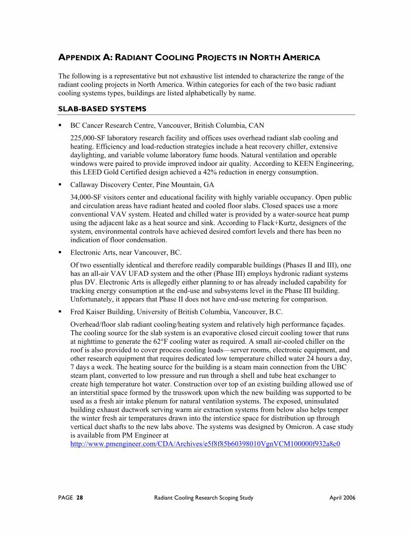
PAGE 28 Radiant Cooling Research Scoping Study April 2006
APPENDIX A: RADIANT COOLING PROJECTS IN NORTH AMERICA
The following is a representative but not exhaustive list intended to characterize the range of the radiant cooling projects in North America. Within categories for each of the two basic radiant cooling systems types, buildings are listed alphabetically by name.
SLAB-BASED SYSTEMS
BC Cancer Research Centre, Vancouver, British Columbia, CAN
225,000-SF laboratory research facility and offices uses overhead radiant slab cooling and heating. Efficiency and load-reduction strategies include a heat recovery chiller, extensive daylighting, and variable volume laboratory fume hoods. Natural ventilation and operable windows were paired to provide improved indoor air quality. According to KEEN Engineering, this LEED Gold Certified design achieved a 42% reduction in energy consumption.
Callaway Discovery Center, Pine Mountain, GA
34,000-SF visitors center and educational facility with highly variable occupancy. Open public and circulation areas have radiant heated and cooled floor slabs. Closed spaces use a more conventional VAV system. Heated and chilled water is provided by a water-source heat pump using the adjacent lake as a heat source and sink. According to Flack+Kurtz, designers of the system, environmental controls have achieved desired comfort levels and there has been no indication of floor condensation.
Electronic Arts, near Vancouver, BC.
Of two essentially identical and therefore readily comparable buildings (Phases II and III), one has an all-air VAV UFAD system and the other (Phase III) employs hydronic radiant systems plus DV. Electronic Arts is allegedly either planning to or has already included capability for tracking energy consumption at the end-use and subsystems level in the Phase III building. Unfortunately, it appears that Phase II does not have end-use metering for comparison.
Fred Kaiser Building, University of British Columbia, Vancouver, B.C.
Overhead/floor slab radiant cooling/heating system and relatively high performance façades. The cooling source for the slab system is an evaporative closed circuit cooling tower that runs at nighttime to generate the 62°F cooling water as required. A small air-cooled chiller on the roof is also provided to cover process cooling loads—server rooms, electronic equipment, and other research equipment that requires dedicated low temperature chilled water 24 hours a day, 7 days a week. The heating source for the building is a steam main connection from the UBC steam plant, converted to low pressure and run through a shell and tube heat exchanger to create high temperature hot water. Construction over top of an existing building allowed use of an interstitial space formed by the trusswork upon which the new building was supported to be used as a fresh air intake plenum for natural ventilation systems. The exposed, uninsulated building exhaust ductwork serving warm air extraction systems from below also helps temper the winter fresh air temperatures drawn into the interstice space for distribution up through vertical duct shafts to the new labs above. The systems was designed by Omicron. A case study is available from PM Engineer at http://www.pmengineer.com/CDA/Archives/e5f8f85b60398010VgnVCM100000f932a8c0
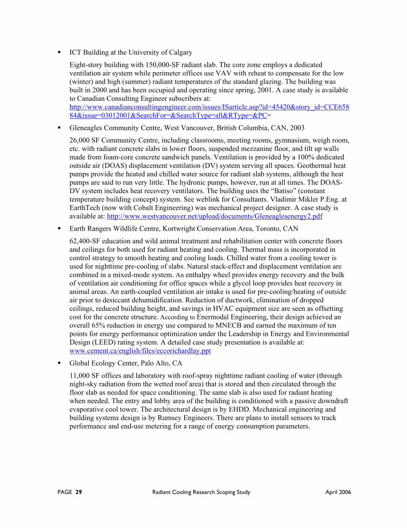
PAGE 29 Radiant Cooling Research Scoping Study April 2006
ICT Building at the University of Calgary
Eight-story building with 150,000-SF radiant slab. The core zone employs a dedicated ventilation air system while perimeter offices use VAV with reheat to compensate for the low (winter) and high (summer) radiant temperatures of the standard glazing. The building was built in 2000 and has been occupied and operating since spring, 2001. A case study is available to Canadian Consulting Engineer subscribers at: http://www.canadianconsultingengineer.com/issues/ISarticle.asp?id=45420&story_id=CCE65884&issue=03012001&SearchFor=&SearchType=all&RType=&PC=
Gleneagles Community Centre, West Vancouver, British Columbia, CAN, 2003
26,000 SF Community Centre, including classrooms, meeting rooms, gymnasium, weigh room, etc. with radiant concrete slabs in lower floors, suspended mezzanine floor, and tilt up walls made from foam-core concrete sandwich panels. Ventilation is provided by a 100% dedicated outside air (DOAS) displacement ventilation (DV) system serving all spaces. Geothermal heat pumps provide the heated and chilled water source for radiant slab systems, although the heat pumps are said to run very little. The hydronic pumps, however, run at all times. The DOAS-DV system includes heat recovery ventilators. The building uses the “Batiso” (constant temperature building concept) system. See weblink for Consultants. Vladimir Mikler P.Eng. at EarthTech (now with Cobalt Engineering) was mechanical project designer. A case study is available at: http://www.westvancouver.net/upload/documents/Gleneaglesenergy2.pdf
Earth Rangers Wildlife Centre, Kortwright Conservation Area, Toronto, CAN
62,400-SF education and wild animal treatment and rehabilitation center with concrete floors and ceilings for both used for radiant heating and cooling. Thermal mass is incorporated in control strategy to smooth heating and cooling loads. Chilled water from a cooling tower is used for nighttime pre-cooling of slabs. Natural stack-effect and displacement ventilation are combined in a mixed-mode system. An enthalpy wheel provides energy recovery and the bulk of ventilation air conditioning for office spaces while a glycol loop provides heat recovery in animal areas. An earth-coupled ventilation air intake is used for pre-cooling/heating of outside air prior to desiccant dehumidification. Reduction of ductwork, elimination of dropped ceilings, reduced building height, and savings in HVAC equipment size are seen as offsetting cost for the concrete structure. According to Enermodal Engineering, their design achieved an overall 65% reduction in energy use compared to MNECB and earned the maximum of ten points for energy performance optimization under the Leadership in Energy and Environmental Design (LEED) rating system. A detailed case study presentation is available at: www.cement.ca/english/files/eccorichardlay.ppt
Global Ecology Center, Palo Alto, CA
11,000 SF offices and laboratory with roof-spray nighttime radiant cooling of water (through night-sky radiation from the wetted roof area) that is stored and then circulated through the floor slab as needed for space conditioning. The same slab is also used for radiant heating when needed. The entry and lobby area of the building is conditioned with a passive downdraft evaporative cool tower. The architectural design is by EHDD. Mechanical engineering and building systems design is by Rumsey Engineers. There are plans to install sensors to track performance and end-use metering for a range of energy consumption parameters.

PAGE 30 Radiant Cooling Research Scoping Study April 2006
Institute for Computing, Information, and Cognitive Systems (ICICS) at the University of British Columbia, BC, CAN
This six-story expansion and new lecture pavilion includes 70,000-SF of radiant cooling and heating slab systems. Keen Engineering believes the range of strategies they employed will result in 52% better energy efficiency and a 75% reduction in greenhouse gas emissions relative to a code-compliant design. Principal strategies included first optimizing building envelope and lighting levels to reduce heat gain, thus permitting a smaller cooling system. A heat recovery chiller serves as the primary thermal source for the slab system. The addition of natural ventilation added to reduction of HVAC demands and equipment size. Operable windows throughout plus underfloor air distribution on three of six floors were included with the aim of improved indoor air quality.
Irving Barber Learning Centre at University of British Columbia, Vancouver, BC, Canada
A radiant slab provides radiant exchange via both floor and ceiling surfaces. Ventilation is provided by a mechanical dedicated outside air system. This building may have appropriate metering for performance data collection, but it’s unclear yet whether that was implemented as planned. Mechanical systems were designed by EarthTech.
MacLeod II ECE Building at the University of British Columbia, BC, CAN, 2004
60,000 SF of radiant cooling and heating slab systems with induced natural ventilation with “demand controlled ventilation controls” (Geoff McDonell P.Eng., Omicron Consultants Architectural and Mechanical). Uses campus central plant steam for heating and a fluid cooler for nighttime slab pre-cooling.
Pier One, San Francisco, 2000
160,000-SF office space retrofit of a 1930s warehouse—originally a cargo terminal for sugar—using 132,000 feet of cross-linked polyethylene tubing for radiant heating and cooling of floor slabs. A case study published by BNP is available at: http://www.pmengineer.com/CDA/ArticleInformation/features/BNP__Features__Item/0,2732,67399,00.html
Star Mart, Davis, CA
3,900 SF gas station, convenience store, and fast-food outlet with nighttime evaporative pre-cooling (cooling-tower-only chilled water source) of a radiant floor slab to cover daytime “base load.” A 10-ton compressor-based packaged rooftop unit provides additional cooling to meet peak loads. According to Davis Energy Group, the designer of this system, actual monitored cooling energy savings are 50% and, based on this, the design is expected to save $3,000 annually and pay for the incremental cost of the evaporative pre-cooling and radiant slab systems in just under one year (incremental cost takes credit for downsizing the conventional rooftop system from 15 to 10 tons).
St. Meinrad Archabbey Church, IN
12,000-SF Gothic church with highly variable occupancy (small numbers on daily basis and about 500 people on holy days) was originally built in the 1900s and recently retrofit with radiant heating and cooling over the original floor. Variable-air-volume perimeter displacement ventilation is controlled by a space air sensor, while floor temperature is controlled by a wall-mounted sensor. The system was designed by Flack+Kurtz.
PAGE 31 Radiant Cooling Research Scoping Study April 2006
Westmont High School Science Education Facility, Campbell, CA, 2004
12,360-SF including classrooms, laboratories, and support facilities has radiant floor slabs pre-cooled at night by chilled water from a cooling tower and heated in winter by a condensing boiler. According to Rumsey Engineers, designers of system and consultants on related aspects of building optimization and systems integration, the low-energy heating and cooling for this facility uses 40% less energy than a standard design.
William Jefferson Clinton Presidential Center, Little Rock, AK, 2004
Radiant heating and cooling via floor slabs throughout the building are combined with demand-controlled conditioned displacement ventilation (selected with the 30-ft tall museum space in mind).
PANEL-BASED SYSTEMS
Centre High, Edmonton, Alberta, CAN 1997
3,100 renovated timber frame and brick warehouse using radiant heating and cooling panels.
GAP retail store, 1996
This retail clothing store uses suspended radiant heating and cooling panels plus mechanical displacement ventilation.
Green on the Grand, Kitchener, Ontario, 1996
23,000 SF office building includes approximately 6,000 SF of radiant heating and cooling panels. According to Enermodal Engineering, annual energy costs are 28% lower than a comparable ASHRAE 90.1-compliant building. A case study is available at: www.enermodal.com/greenongrand.html
Architecture Studios Building, Penn State University, University Park, PA, 2001
3,200-SF architecture studio space serving 40 students uses 640 SF of suspended panels plus a 100%-OA dedicated outside air (DOAS) ventilation system for to handle latent loads.
Imperial Oil Building, Toronto, Ontario, CAN mid 1960’s
Originally used copper pipe imbedded in the plaster walls and ceilings that gradually (over 30-plus years) began to leak as a result of corrosion from inappropriate water treatment. A 1990’s retrofit installation of radian radiant panels sought to address these problems and improve temperature control and comfort.
National Works Yard, City of Vancouver, Omicron
A ground source heat pump & radiant heating cooling system is said by Omicron to reduce energy use by 40% (this may include some energy savings from other measures).

PAGE 32 Radiant Cooling Research Scoping Study April 2006
NOAA Lab, Hawaii, 2002 design
This radiantly cooled design was shelved with the project shift to renovation of an existing building, now planned to use wind catchers, passive downdraft evaporative cooling, and stack-effect natural ventilation via underfloor air distribution systems.
The original 2002 design separated temperature control, dehumidification, and ventilation. Radiant cooling ceiling panels were to use chilled water from a solar-heated absorption chiller. Individual room temperature sensors would have controlled room temperatures by regulating the flow of chilled water to the radiant ceiling panels. Outside air was to be dehumidified by a solar-regenerated desiccant system using heat from roof-mounted solar thermal collectors. A phase-change material was to store heat from the thermal collectors for use when insolation was inadequate. Ventilation was designed to use 100% outside air.
Kaiser Center, Oakland, CA, high-rise office building, mid-1960s
Twenty-three stories of office space were originally cooled by a hydronic system using steel pipes with approximately 650,000 SF of ceiling-integrated aluminum panels clamped to them. Given typical 1960s office space internal loads as the basis for design, poorly insulated façades with single-pane glazing, ineffective thermal connections between chilled water pipes and the ceiling panels, and lacking integration with airside system design, the system capacity proved inadequate for handling the much larger internal loads introduced in the 1980’s. This in turn forced excessive dependence on the 100%-OA ventilation system for removal of loads, and thus also excessive energy consumption. On-site tests and analysis documented in a detailed case study by International Energy Studies, Inc. at www.tga-feustel.de/ies/kaiser.html indicate that retrofitting newer radiant cooling panels with higher capacity at same operating temperatures, along with revision of ventilation diffuser and exhaust locations, would effectively address these issues.
La Loch General Hospital, La Lock, Saskatchewan, CAN
8,000 SF of radiant heating and cooling panels are used in conjunction with a constant-volume overhead ventilation system.
Fox Pavilion Building: built late ‘60’s, Jenkinstown, PA
Nine-story office building using radiant cooling panels integrated with the lights (Lithonia Lighting). According to information provided by Omicron Consulting, the design saved floor-to-floor height to allow an economically viable building to be developed.
Manulife Building, Toronto, Ontario
Incorporated radiant panels with chilled water for supplemental space cooling.
Segal Hall, Simon Fraser University, Vancouver, BC
52,000-SF renovation of a 1915 Heritage building. Uses suspended radiant heating/cooling panels as a supplement to space conditioning with displacement ventilation (DV), including perimeter temperature control. Dedicated outside air ventilation is supplied by the DV system to all spaces. The 100% outside air supply uses heat recovery ventilators and is tempered as needed by chilled and heated water coils.
ST Dana Hall, School of Natural Sciences and Environment, University of Michigan, 2002
90,000-SF facility including classrooms, labs, and offices with 13,300 SF of suspended radiant panels for cooling only plus a constant-volume overhead ventilation system.

PAGE 33 Radiant Cooling Research Scoping Study April 2006
Suncor Accommodation Complex, Fort McMurray, Alberta, 1999
120,000-SF, 1,500-room employee dormitory with radiant heating and cooling panels in each room and, according to information provided by Omicron consulting, yielded savings in both first costs and electric utility costs.
United States Veterans Administration Hospitals
For over 40 years radiant cooling has been used in patient rooms and other areas in the VA Hospitals across the US. Hundreds of thousands of SF currently conditioned with radiant cooling panels. For more information: Airtite Contractors, Paul Nider, 440-356-0040.
Wellesley Hospital, Windsor, Ontario, 1994
Valence cooling panels are provided in each room.
PAGE 34 Radiant Cooling Research Scoping Study April 2006
REFERENCES
Bauman, F. 2003. Underfloor Air Distribution (UFAD) Design Guide. Atlanta: ASHRAE, American Society of Heating, Refrigerating, and Air-Conditioning Engineers.
Bauman, F., H. Jin, and T. Webster. 2006. "Heat Transfer Pathways in Underfloor Air Distribution (UFAD) Systems." To be published in ASHRAE Transactions, Vol. 112, Part 2.
Carpenter S. and J. Koklo, 1988. “Radiant Heating and Cooling, Displacement Ventilation with Heat Recovery and Storm Water Cooling: An Environmentally Responsible HVAC System,” ASHRAE Transactions, v. 4, part.
Carpenter, S R. Lay, 2003 “Radiant Cooling Systems – A Solution for LEED Buildings in Temperate Climates” Enermodal Engineering Ltd., Kitchener Ontario
Conroy, C. and S.A. Mumma. 2001. “Ceiling radiant cooling panels as a viable distributed parallel sensible cooling technology integrated with dedicated outdoor-air systems.” ASHRAE Transactions 107(1):571–579.
Feustel, H. 1994. “Hydronic Radiant Cooling Systems.” Center for Building Science News (Fall issue), Lawrence Berkeley Laboratory
FT Energy EDR Design Brief. “Radiant Cooling Design Brief” prepared by Financial Times Energy, Boulder, CO for Energy Design Resources. www.energydesignresources.com
Jeong, J., S. A. Mumma and W. P. Bahnfleth. 2003. “Energy conservation benefits of a dedicated outdoor air system with parallel sensible cooling by ceiling radiant panels.” ASHRAE Transactions 109(2).
Jin, H., F. Bauman, and T. Webster. 2006. "Testing and Modeling of Underfloor Air Supply Plenums." To be published in ASHRAE Transactions, Vol. 112, Part 2.
Keller, B. “Low Temperature Heating and Cooling Systems for Low-Energy Buildings, Proved in Practice” Institute of Building Technology, ETH-Z (Swiss Federal Institute of Technology), Zurich, Switzerland
Kulpmann, R.W. 1993. Thermal comfort and air quality in rooms with cooled ceilings—Results of scientific investigations. ASHRAE Transactions 99(2): 488-502.
McCarry, B. 2006. Personal communication. Stantec, Vancouver, BC, Canada
McDonnell, G. 2005. Personal Communication. Omicron, Vancouver, BC, Canada
McGinn, T. 2005. Personal communication. Keen Engineering, Vancouver, BC, Canada
Meierhans, R.A. 1996. “Room air conditioning by means of overnight cooling of the concrete ceiling.” ASHRAE Transactions. 102(2).
Mikler, V. 1999. In-house design guidelines. Cobalt Engineering, Vancouver, BC
Mikler, V. 2006. Personal communication. Cobalt Engineering, Vancouver, BC
Mumma, S.A. 2002. “Chilled ceilings in parallel with dedicated outdoor air systems: Addressing the concerns of condensation, capacity, and cost.” ASHRAE Transactions 108(2):220–231.
Mumma, S.A. 2001. “Dedicated outdoor air in parallel with chilled ceiling systems.” Engineered Systems 18(11):56–66.
PAGE 35 Radiant Cooling Research Scoping Study April 2006
Olesen, B W. 2002. Radiant Floor Heating in Theory and Practice. ASHRAE Journal, July 2002, pp. 19-26.
Olesen, B.W. 2000. “Hydronic Radiant Heating and Cooling of Buildings Using Pipes Embedded in the Building Structure.” 41 AICARR Conference.
Rea, M., R. Zechin, B.Olesen, and M. De Carli, 2001. New Technologies in Radiant Heating and Cooling Università Degli Studi Di Padova, Dipartimento di Fisica Tecnica, Tesi di Dottorato in Energetica, XIV Ciclo
Shank, K. and S.A. Mumma. 2001. “Selecting the supply air conditions for a dedicated outdoor air system working in parallel with distributed sensible cooling terminal equipment.” ASHRAE Transactions 107(1):562–570.
Simmonds, P. Holst, S. Gaw, W. and Reuss, S. “Using Radiant Cooled Floors to Condition Large Spaces and Maintain Comfort Conditions.” ASHRAE Transactions 2000, V.106 pt 1
Simmonds, P. and B. Mehlomakulu. 2006. “Radiant Cooled Floors: Operation and Control Dependent Upon Solar Radiation.” To be published in ASHRAE Transactions, V. 112
Simmonds, P., B. Mehlomakulu, I. Chambers, and C. Simmonds. 2006. “Applied Performance of Radiant Ceiling Panels for Cooling.” To be published in ASHRAE Transactions, V. 112
Simmonds, P. 1996. “Practical applications of radiant heating and cooling to maintain comfort conditions.” ASHRAE Transactions 102(1): 659-666.
Simmonds, Peter, 2006 personal communication. IBE Consulting Engineers, 14130 Riverside Dr., #201, Sherman Oaks, CA 91423.
Stetiu, C. 1999. “Energy and Peak Power Savings Potential of Radiant Cooling Systems in U.S. Commercial Buildings,” Energy and Buildings, v.30, no.2
Webster, T., F. Bauman, J. Reese. 2002. “Underfloor Air Distribution: Thermal Stratification,” ASHRAE Journal, May.
Zent-Fenger mbH. Product literature and design guidelines. www.zent-frenger.de
Zurn. Product literature and independent testing. www.Zurn.com