r fighter 1110 - nibeonline.com · in order to get the ultimate benefit from your heat pump fighter...
TRANSCRIPT

RINSTALLATION AND MAINTENANCE INSTRUCTIONS
FIGHTER 1110MOS GB 0337-1 611843FIGHTER 1110
+2
0
-2
1
R
0
LEK


For the Installer
Contents 1
FIGHTER 1110
For Home Owners
General points for the installation engineerTransport and storage .......................................... 14Installation ............................................................ 14Floating condensing ............................................ 14Fixed condensing ................................................ 14Guideline values for collectors ............................ 14Inspection of the installation ................................ 14
Control (also with accessories)General ................................................................ 15Settings ................................................................ 15Drying process ......................................................17
Pipe connectionsGeneral ................................................................ 18Heating medium pump ........................................ 18Pipe connections (brine) .................................... 18Pipe connections (heating medium) .................... 18Ventilation recovery .............................................. 18Free cooling ........................................................ 18Pump capacity diagrams, heating medium side .. 19
DockingGeneral ................................................................ 20Option 1 – immersion heater and water heater .... 20Option 2 – as option 1 with room sensor only ...... 21Option 3 – oil-fired boiler ...................................... 21Option 4 – double shelled boiler .......................... 22Option 5 – double shelled water heater .............. 22Option 6 – firewood boiler .................................... 23Option 7 – immersion heater, double curves ...... 23Option 8 – boiler, double curves .......................... 24Abbreviations ...................................................... 24
Electrical connectionsRemoving the covers .......................................... 25Electrical installation ............................................ 25Connection, 3-phase and 1-phase 4 kW .............. 26Connection, 1-phase ..............................................26Connecting the outside sensor ............................ 26External control of the immersion heater ............ 27Connecting the supplied temperature sensor
with floating condensing .................................... 27Connecting the supplied temperature sensor
with fixed condensing ........................................ 27Connection of heating medium pump,
fixed condensing ................................................ 27
Control with oil supplementConnecting ............................................................ 28Function, oil supplement ........................................29
Control with electrical supplement in seven stepsConnecting ............................................................ 30Function, immersion heater....................................31
Control, double curvesConnecting .......................................................... 32Control, double curves with external shunt ............33
Commissioning and adjustingPreparations ........................................................ 34Filling and venting the heat transfer system ........ 34Filling the heating/heating medium system .......... 35Start-up and inspection ........................................ 35Readjustment, heating medium side .................... 35Readjustment, heat transfer side ........................ 35Drying process ......................................................36
Setting the automatic heating control systemSetting using diagrams with diagrams ................ 37Heating curve offset -2 ........................................ 37Heating curve offset 0 .......................................... 37Heating curve offset +2 ........................................ 37
Component locationsComponent locations .......................................... 38
List of componentsList of components .............................................. 39
Electrical circuit diagram Wiring diagram 3-phase/1-phase 4 kW ................ 40Circuit diagram 3-phase/1-phase 4 kW ................ 41Wiring diagram 1-phase ........................................42Circuit diagram 1-phase ........................................43
DimensionsDimensions and setting-out coordinates .............. 44
AccessoriesAccessories .......................................................... 45
Technical dataTechnical data 3-phase ........................................ 46Technical data 1-phase..........................................47
Enclosed kitEnclosed kit .......................................................... 48
Dealing with malfunctionsLow room temperature ........................................ 49High room temperature ........................................ 49Low temperature or a lack of hot water ................ 49Indications ............................................................ 50Draining, heat medium side ................................ 51Draining, heat transfer fluid side .......................... 51Helping the circulation pump to start .................... 51
GeneralConcise product description ................................ 2Setting table ........................................................ 2
System descriptionPrinciple of operation .......................................... 3
Front panelFront panel .......................................................... 4Functions .............................................................. 5Setting different operating modes (even with
accessories) ...................................................... 5
ControlsGeneral ................................................................ 6Setting heat .......................................................... 6Changing the room temperature .......................... 6Basic values ........................................................ 7Domestic hot water .............................................. 7Electric boiler mode .............................................. 7Heat transfer pump .............................................. 7Fixed condensing ................................................ 7
Control, normalInformation available on the display .................... 8
Control, double curvesInformation available on the display .................. 11

General
FIGHTER 1110
For Home Owners
2In order to get the ultimate benefit from your heat pump FIGHTER 1110 you should read throughthe For Home Owners section in this Installation and Maintenance Instruction.
FIGHTER 1110 is a base heat pump for heating small houses, apartment blocks and industrial premis-es. The ground, rock or lakes can be used as the heat source.
FIGHTER 1110 is a Swedish made quality product offering a long life span and safe operation.
Completed by the installation engineer when the heat pump is installed
Installation date
Accessories: Electrical supplement .. Room control ..............
Hot water control ........ Oil supplement ............
Load monitor ................ Other ..........................
The serial number (95), should always be stated with all correspondence with NIBE, 689 _ _ _ _ _ _ _ _ _ _ _FIGHTER 1110- _ _ kW
Installation engineers
The type of brine – Mixing proportion/freezing point
Active drilling depth/collector length
Menu Basic setting
2 Room * ..............
3 WW-in .............. A
3 HW start .............. 44
4 Brine Out .............. -12
5 Curveslope .............. 9
5 Room-comp +/-*............ 4
5b WW-out min .............. 15
5b WW-out max .............. 45
9b HP-°min .............. 60
9b Add-min .............. 300
Menu Basic setting
10 WW diff HP .............. 13
10 Diff HP-Add .............. 3
11 HP-int .............. 20
11 HWT-stop .............. 50
12 XWW-stop .............. 65
12 XWW interval .............. 14
12b Shunt P .............. 30
12b Shunt time .............. 10
17 Parallel ..............
18 Shunt .............. 1
Date ________ Signed ____________________________
* Accessories
Commissioning checksTemperature brine (flow/return)____ / ____ Pump setting ___
(Nominal temperature diff 2 - 5 °C)
Temperature heat medium (in/out) ____ / ____ Pump setting ___(Nominal temperature diff 5 – 10 °C)
Control, double curves
Menu Basicsetting
5 Curveslope 1 .............. 95 Curveslope 2 .............. 95b Parallel 1 .............. 05b Parallel 2 .............. 05c WW-Out 1 min .............. 105c WW-Out 1 max .............. 455d WW-Out 2 min .............. 105d WW-Out 2 max .............. 45

FIGHTER 1110 consists of a heat pump module and acontrol computer with a display for operating the heatpump and additional heat (immersion heater notincluded in the basic design). FIGHTER 1110 has inte-grated circulation pumps making it easy to connect toboth the brine and heating medium circuits.The absorption of heat from the heat source (rock,ground or lake) is through a closed heat transfer sys-tem containing water mixed with antifreeze.
Ground water can also be used as a heat source. Thisrequires an intermediate heat exchanger.The brine emits its heat to the refrigerant in the heatpump’s evaporator. It then vaporises and is com-pressed in the compressor. The refrigerant, with itsincreased temperature, is led into the condenserwhere it emits its energy to the heat medium circuit.
System description 3For Home Owners
FIGHTER 1110
Principle of operation
Brine out Cirk.pump
Värmepump
Varmvatten
Tillsatsvärme
Larm
Kontrollera
att vatten
finns i pan-
nan innan
den in-
kopplas.
1
R
0
Compressor Radiator
Horizontal loop collector Vertical loop collector
Heating water pump
Condenser
Expansion valve
Brine in
Evaporator
Brine pump
Heating water flow
Heating water return
The heating medium side and the hotwater side must be fitted with the nec-essary safety equipment in accor-dance with the applicable regulations.

+20
-2
1
R
0
WW-out 49 (50) °CHot-water 51 °C
Front panel
FIGHTER 1110
For Home Owners
4
Indicator lampsFunction keys
Display
Front panel
B
Switch
A
D
Increase/decreaseheat
C
E
NOTE! Make sure there is water in the heat pump
before putting switch (A) into position 1 or R.

Power switchThree-position switch (1 – 0 – R)0 Heat pump off.1 Normal mode. All control functions connected.R Spare mode, only heating medium pump and
electrical additional. Not connected at the fac-tory.
Function keysChannelTo choose window menu.
IncreaseTo increase the current value.
DecreaseTo decrease the value currentlydisplayed.
Operating modeConnecting and disconnecting the addi-tional heat (accessory) and/or room tem-perature. See the following section.
Extra hot waterTemporary or periodic increase in the hotwater temperature.
DisplayIn normal mode the display shows:1 WW Out: The current temperature of the heat
medium (the temperature of the water comingout of the heat pump).Hot-water: The current hot water temperature(accessory, for docking options 1, 2 and 3).
Indicator lampsRoom heating– Shows room heating is allowed when lit
(circulation pump in operation).Heat pump– Shows the compressor is running when
lit.Hot water (accessory)– A steady light shows that hot water
charging is in progress.– Flashes rapidly when temporary
increase of the hot water temperature isselected (approx. 60 °C during 24hours).
– Flashes slowly when periodic increaseof the hot water temperature is selected(approx. 60°C in accordance with theselected interval).
Additional heat (accessory)– Shows that additional heat is switched
on when lit.– Flashes slowly when additional heat is
allowed.– Flashes rapidly when only additional
heat is allowed.AlarmsFlashes rapidly when a fault has occurred.
Increase/decrease heatThe Raise/lower heat knob raises or lowers theroom temperature (changes the temperature ofWW-out). Applies to docking options 1, 2, 3 and 4.
Front panel 5For Home Owners
FIGHTER 1110
B
A
C
E
Functions
D
Normal mode (basic setting): Additional heatready to start if needed. Hot water charging cutsin if needed.
LEDs:Room heating: LitHot water: Lit during hot water chargingAdditional heat: Flashes/LitNo additional heat mode: Press the Operating modebutton once.LEDs:Room heating: LitHot water: Lit during hot water chargingAdditional heat: Not litNo room heating mode (only hot water): Press theOperating mode button again.LEDs:Room heating: Not litHot water: Lit during hot water chargingAdditional heat: Not lit
The system returns to normal mode the next time theOperating mode button is pressed.
Normal mode: No raised hot water temperatureconnected.
Temporarily raised hot water temperature: Pressthe Extra hot water button once. A raised hot watertemperature is obtained for 24 hours. The Hot waterLED flashes rapidly. Lit during charging.Periodically raised hot water temperature: Pressthe Extra hot water button again. The hot water tem-perature is raised as shown on menu 12. The Hotwater LED flashes slowly. Lit during hot water charg-ing.The next time the Extra hot water button is pressed,the system returns to normal mode.
Setting different operating modes (even with accessories)

ControlFor Home Owners
6
FIGHTER 1110
Setting takes place by programming the ”Curveslope”, see the ”Available information and settings onthe display” section, and by setting the ”Heating curveoffset” using the ”Increase/decrease” heat knob on thepanel.Initial values can be taken from the map if you do notknow which values to set, see the ”Control Basic val-ues” section.If the required room temperature is not obtained, read-justment may be necessary.NOTE! Wait one day between settings so that thetemperatures have time to stabilise.
Readjusting the settingCold weather conditions
If the room temperature is too low, increase thevalue for the heating curve by one step.If the room temperature is too high, decrease thevalue for the heating curve by one step.
Warm weather conditionsIf the room temperature is too low, turn the”Increase/decrease heat” knob one step clockwise.If the room temperature is too high, turn the”Increase/decrease heat” knob one step anticlock-wise.
The indoor temperature depends on several factors.Sunlight and heat emissions from people and house-hold machines are normally sufficient to keep thehouse warm during the warmer parts of the year.When it gets colder outside, the heating system mustbe started. The colder it is outside, the warmer radia-tors and floor heating system must be. FIGHTER 1110controls this automatically through a computer, butcorrect basic setting must first be made. FIGHTER1110 also offers the possibility to control two differenttemperature curves.The heat pump is controlled by built-in sensors forflow and return heat transfer fluid temperatures (col-lector). The brine return temperature can, if sorequired, be limited to a minimum (e.g. for groundwater systems).Heat production is usually controlled using the floatingcondensing principle. This means that the tempera-ture level needed for heating at a given outside tem-perature is produced on the basis of values taken fromsensors for outside temperature and flow temperature(see docking options 1, 2, 3 and 4). As an option,room sensors can also be used to compensate fordeviations in room temperature.
GeneralChanging the room temperature manuallyIf you want to temporarily or permanently increase orlower the indoor temperature in relation to the previ-ous heat setting turn the ”Increase/decrease heat”knob clockwise or anticlockwise. One line approxi-mately represents a 1 degree change in the room tem-perature. NOTE! An increase in the room temperature may be”inhibited” by the radiator or floor heating thermostats,if so these must be turned up.
Changing the room temperature
Setting heat

Control 7For Home Owners
If the FIGHTER 1110 is fitted with the ”Electrical sup-plement” accessory the unit can be used solely as anelectric boiler to produce heat and hot water. This isespecially useful, for example, before the collectorinstallation is finished.
The brine pump normally follows the operation of theheat pump. There is a special operating mode for con-tinuous operation for 10 days, followed by return tonormal mode (used before stable circulation has beenestablished).
FIGHTER 1110 can also be docked to an external unitwith its own heating controls. FIGHTER 1110 thensupplies heating up to a permanent temperature level.This is known as ”Fixed condensing”. To regulate the room temperature, see the instructions for theexternal units.
FIGHTER 1110 can be supplemented with ”Hot watercontrol”, VST 11 and, for example, our hot water accu-mulator VPA to produce domestic hot water. NOTE! Only the correct type of water heating cylinder,such as the VPA, may be used. DO NOTE USEOTHER TYPES OF CYLINDERS WITHOUT CON-SULTING THE MANUFACTURER.
The supply of heat to the building is controlled by thecontrol computer settings (curve slope and offset).After adjustment the correct amount of heat for thecurrent outdoor temperature is supplied. The heatpump’s flow temperature (WW-out) will hover aroundthe theoretical required value (the value in brackets onthe display). For subnormal temperatures the comput-er calculates a demand in the form of ”degree min-utes”, which results in the acceleration of heat produc-tion. The larger the subnormal temperature, thegreater the heat production.
Control, normalThe heat pump computer can control an immersionheater in three output steps if fitted, or an external oil-fired boiler and shunt valve.
Control, double curvesCurve 1 controls the operation of the compressors.Curve 2 controls an external shunt at lower tempera-tures. In this operating instance the supplement is limitto one step.
Heat production Hot water production
Electric boiler mode
Brine pump
Fixed condensing
FIGHTER 1110

Control, normal
FIGHTER 1110
For Home Owners
8
FIGHTER 1110 is equipped with a 2 row LCD-display.The heat pump can be set via this display and itsassociated buttons.
Channel selectionThe ”Channel” button lets you browse throughthe following display modes to find the informa-
tion you require. Values within brackets are also described withinbrackets.If a value is programmable, this is denoted by a [P](Programmable) in front of the value.If the next value cannot be changed, you can accessthe next menu by pressing Channel.
Setting upThe first step when changing a value is to pressthe ”Increase” button once. A cursor (line) thenappears under the value. Now you can eitherincrease or decrease the value with the”Increase” or ”Decrease” buttons.
Available information and on-display settings
In normal mode, the above information appears onthe LCD display of the heat pump.WW-out
Current flow temperature(Calculated flow temperature.)
Hot waterIndication of the hot water temperature.
1
OutdoorActual outdoor temperature.
RoomActual room temperature. Only shown if a roomsensor is connected[P] (Target value set on room sensor.)Setting range: 5 – 30 °C.
OutdoorActual outdoor temperature.
Temp inkTemperature drop, the heating curve is lowered,for example, by 8 degrees when the contact inthe room unit (accessory) makes. If the room unitis connected a room sensor cannot be con-nected.[P] (Set the set point value for temperatur dropp.)Setting range: 5 – 30 °C.
2
2c
Boiler *Current boiler water temperature.(Start temperature for shunting from the boiler).
* Only displayed if a boiler sensor is connected.
2b
NOTE! If the system is to be controlled
according to two temperature curves see the section,
”Control, double curves”.
WW-out 47(52) °CHot water 48 °C Outdoor -14 °C
Room 20,5(20) °C
Outdoor -14 °CBoiler 70(55) °C
Outdoor -14 °CTemp ink 8 °C
Control, normal 9For Home Owners
FIGHTER 1110
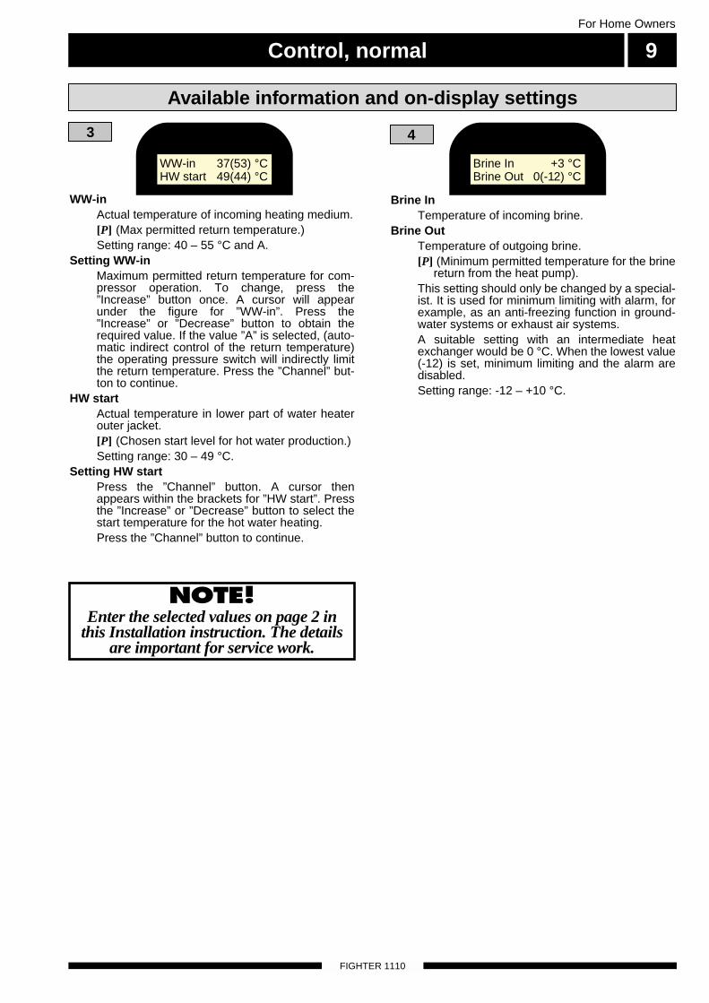
WW-inActual temperature of incoming heating medium.[P] (Max permitted return temperature.)Setting range: 40 – 55 °C and A.
Setting WW-inMaximum permitted return temperature for com-pressor operation. To change, press the”Increase” button once. A cursor will appearunder the figure for ”WW-in”. Press the”Increase” or ”Decrease” button to obtain therequired value. If the value ”A” is selected, (auto-matic indirect control of the return temperature)the operating pressure switch will indirectly limitthe return temperature. Press the ”Channel” but-ton to continue.
HW startActual temperature in lower part of water heaterouter jacket. [P] (Chosen start level for hot water production.)Setting range: 30 – 49 °C.
Setting HW startPress the ”Channel” button. A cursor thenappears within the brackets for ”HW start”. Pressthe ”Increase” or ”Decrease” button to select thestart temperature for the hot water heating.Press the ”Channel” button to continue.
3
NOTE! Enter the selected values on page 2 in
this Installation instruction. The detailsare important for service work.
Brine InTemperature of incoming brine.
Brine OutTemperature of outgoing brine.[P] (Minimum permitted temperature for the brine
return from the heat pump). This setting should only be changed by a special-ist. It is used for minimum limiting with alarm, forexample, as an anti-freezing function in ground-water systems or exhaust air systems.A suitable setting with an intermediate heatexchanger would be 0 °C. When the lowest value(-12) is set, minimum limiting and the alarm aredisabled.Setting range: -12 – +10 °C.
4
Available information and on-display settings
WW-in 37(53) °CHW start 49(44) °C
Brine In +3 °CBrine Out 0(-12) °C

Control, normal
FIGHTER 1110
For Home Owners
10
Curveslope[P] Set heating curve.Setting range: 1 – 15.
Setting the curveslopePress the ”Increase” button once. A cursor appearsunder the figure for curveslope. Press either the”Increase” or ”Decrease” button to set the requiredcurveslope.Press the ”Channel” button to continue.Room-comp
[P] When the room temperature differs by 1 °Cchange the set point value WW-out with the indi-cated value.A higher value gives a quicker reaction to excessor low indoor temperatures. The normal value fora radiator system is 4.
Setting range: 0 – 6 °C)Setting room-comp(Only applies if a room sensor is connected).
After setting the curve slope, press the ”Channel”button. The cursor moves under the figure for”Room-comp”. Change the figure using the”Increase” or ”Decrease buttons”. A higher valuegives a quicker reaction to excess or low indoortemperatures. The normal value for a radiator sys-tem is 4.
5
5b
This menu is a submenu to menu 5a and is acti-vated by placing the cursor under the value for”Curveslope” (or ”Room-comp” if a room sensor isconnected) and pressing the ”Channel” button.
WW-out min[P] Setting for the minimum calculated flow tem-perature. Setting range: 10 – 50 °C.Preset value: 15 °C
WW-out max[P] Setting for the maximum calculated flow tem-perature. Setting range: 30 – 70 °C.The preset value is 45 °C. Therefore thisvalue must normally be increased when a radiator system is used.
As the flow temperature normally hovers in relation tothe calculated temperature, values above and belowthe set value can temporarily occur.For example, the suitable values for floor heating withfloating condensing could be min 18 °C, max 40 °C.
Setting WW-out min and WW-out maxPress the ”Increase” button once. A cursor will appearunder the figure for ”WW-out min”. Press either the”Increase” or ”Decrease” button to set the required”WW-out min” value.Press the ”Channel” button to move to ”WW-out” max and change as required.For fixed condensing, 50 °C is suitable for both minand max levels. (sensor placement and pump flowobserved.)
6
7
8
HP start: Counts the starts of the heat pump (cumula-tive).HP off: Shows the operating mode: ”HP off”, ”HP on”,”HP start in X minutes” or ”WW in high”.
HP-time: Shows the total number running hours forheat pump.
Add-time: Shows the total hours of operation foradditional heat.
Basic: Change the left figure from 0 to 1 using the”Increase” button at the same time as pressing the”Operating mode” button to return to the basic settings.The two figures to the right specify the selected oper-ating mode. The middle figure specifies the operatingmode for room heating.0 signifies ”Normal mode”.1 signifies ”No addition”.2 signifies ”No room heating”.The right figure specifies the operating mode for hotwater.0 signifies Normal mode.1 signifies temporary increased hot water temp.2 signifies periodically increased hot water temp.English: Selected language.Setting of languageLanguage selection is accessed the next time ”Channel”is pressed. Press ”Increase” to change language. Whenthe required language is selected, press the ”Channel”button. You then return to display 1.
Available information and on-display settings
WW-out min 15 °CWW-out max 45 °C
HP start 10HP off
HP-time 40 hAdd-time 0 h
Basic 0 00English
Curveslope 9Room-comp 4 °C

Hold the ”Channel” button down for about 7 secondsto access the following menus. Press the ”Channel”button to scroll to channel 18 and select Shunt ”1”.The channels below will then be accessible ”Controls,double curves”.
Control, double curves 11For Home Owners
FIGHTER 1110
Available information and on-display settings
In normal mode, the above information appears onthe LCD display of the heat pump.WW-out
Current flow temperature(Calculated flow temperature.)
Hot waterIndication of the hot water temperature.
1
18
OutdoorCurrent outdoor temperature.
RoomActual room temperature. Only shown if a roomsensor is connected[P] (Target value set on room sensor.)Setting range: 5 – 30 °C.
OutdoorActual outdoor temperature.
Temp inkTemperature drop, the heating curve is lowered,for example, by 8 degrees when the contact inthe room unit (accessories) makes. If the roomunit is connected a room sensor cannot be con-nected.[P] (Set the set point value for temperatur dropp.)Setting range: 5 – 30 °C.
2
2c
WW-out 2Current flow temperature 2.(Calculated flow temperature.)
2b
WW-inActual temperature of incoming heating medium.[P] (Max permitted return temperature.)Setting range: 40 – 55 °C and A.
Setting WW-inMaximum permitted return temperature for com-pressor operation. To change, press the”Increase” button once. A cursor will appearunder the figure for ”WW-in”. Press the”Increase” or ”Decrease” button to obtain therequired value. If the value ”A” is selected, (auto-matic indirect control of the return temperature)the operating pressure switch will indirectly limitthe return temperature. Press the ”Channel” but-ton to continue.
HW startActual temperature in lower part of water heaterouter jacket. [P] (Chosen start level for hot water production.)Setting range: 30 – 49 °C.
Setting HW startPress the ”Channel” button. A cursor thenappears within the brackets for ”HW start”. Pressthe ”Increase” or ”Decrease” button to select thestart temperature for the hot water heating.Press the ”Channel” button to continue.
3
Shunt ”0” or ”1”Shunt = ”0” Normal control, supplement electric boiler or oil-fired boiler. Shunt = ”1” Control, double curves.
A system with ”Control, double curves” means thatcontrol of the shunt valve takes place against curveslope 2 and flow temperature 2. The sensor is con-nected to PG on terminal block 31. The shunt valve forcircuit 2 is always operational and is connected toTS1/SH- and TS2/SH+ on terminal block 6.The connection TS3 controls the electrical supple-ment, if fitted. The shunt valve is closed with hot waterheating.
Shunt 1
Outdoor -14 °CTemp ink 21(13) °C
Outdoor -14 °CWW-out 2 47(52) °C
Outdoor -14 °CRoom 20,5(20) °C
WW-out 47(52) °CHot water 48 °C
WW-in 37(53) °CHW start 49(44) °C

Control, double curves
FIGHTER 1110
For Home Owners
12
This menu is a submenu to menu 5 and is activat-ed by placing the cursor under the value for”Curveslope 1” (or ”Room-comp” if a room sensoris connected) and pressing the ”Channel” button.
WW-out 1 min[P] Setting for the minimum calculated flow tem-perature. Setting range: 10 – 50 °C.Preset value: 15 °C
WW-out 1 max[P] Setting for the maximum calculated flow tem-perature. Setting range: 30 – 70 °C.The preset value is 45 °C. This value musttherefore normally be increased when a radiator system is used.
5d
5c
5b
Parallel offset[P] Setting the parallel offset for curve ”1”. Shows
the parallel offset for curve ”2”, which is setusing the ”Increase/decrease heat” knob.
Room-comp[P] When the room temperature differs by 1 °Cchange the set point value WW-out with the indi-cated value.A higher value gives a quicker reaction to excessor low indoor temperatures. The normal value fora radiator system is 4.
Setting range: 0 – 6 °C)Setting room-comp(Only applies if a room sensor is connected).
After setting the curve slope, press the ”Channel”button. The cursor moves under the figure for”Room-comp”. Change the figure using the”Increase” or ”Decrease” buttons. A higher valuegives a quicker reaction to excess or low indoortemperatures. The normal value for a radiator sys-tem is 4.
5
Curveslope[P] Set heating curve.Setting range: 1 – 15.
Brine InTemperature of incoming heat transfer fluid.
Brine OutTemperature of outgoing heat transfer fluid.[P] (Minimum permitted temperature for the heat
transfer fluid return from the heat pump). This setting should only be changed by a special-ist. It is used for minimum limiting with alarm, forexample, as an anti-freezing function in ground-water systems or exhaust air systems.A suitable setting with an intermediate heatexchanger would be 0 °C. When the lowest value(-12) is set, minimum limiting and the alarm aredisabled.Setting range: -12 – +10 °C.
4
Available information and on-display settings
Brine In +3 °CBrine Out 0(-12) °C
Curveslope 1 10Curveslope 2 4
Parallel 1 6Parallel 2 -2
WW-out 1 min 15 °CWW-out 1 max45 °C
Room-comp 4 °C

Control, double curves 13For Home Owners
FIGHTER 1110
Available information and on-display settings
5e
This menu is a submenu to menu 5 and is acti-vated by placing the cursor under the value for”Curveslope 2” (or ”Room-comp” if a room sen-sor is connected) and pressing the ”Channel”button”.
WW-out 2 min[P] Setting for the minimum calculated flow tem-perature. Setting range: 10 – 50 °C.Preset value: 15 °C
WW-out 2 max[P] Setting for the maximum calculated flow tem-perature. Setting range: 30 – 70 °C.The preset value is 45 °C. Therefore thisvalue must normally be increased when a radiator system is used.
As the flow temperature normally hovers in relation tothe calculated temperature, values above and belowthe set value can temporarily occur.For example, the suitable values for floor heating withfloating condensing could be min 18 °C, max 40 °C.Setting WW-out min and WW-out maxPress the ”Increase” button once. A cursor will appearunder the figure for ”WW-out min”. Press either the”Increase” or ”Decrease” button to set the required”WW-out min2 value.
Press the ”Channel” button to move to ”WW-out max” and change as required.
For fixed condensing, 50 °C is suitable for both minand max levels. (sensor placement and pump flowobserved.)
6
7
8
HP startCounts the starts of the heat pump (cumulative).
HP offShows the operating mode: ”HP off”, ”HP on”,”HP start in X min” or ”WW in high”.
HP-time: Shows the total number running hours forheat pump.
Basic: Change the left figure from 0 to 1 using the”Increase” button at the same time as pressing the”Operating mode” button to return to the basic set-tings.The two figures to the right specify the selected oper-ating mode. The middle figure specifies the operatingmode for room heating.0 signifies ”Normal mode”.1 signifies ”No addition”.2 signifies ”No room heating”.The right figure specifies the operating mode for hotwater.0 signifies normal mode.1 signifies temporary increased hot water temp.2 signifies periodically increased hot water temp.English: Selected language.Setting of languageLanguage selection is accessed the next time ”Chan-nel” is pressed. Press ”Increase” to change language.When the required language is selected, press the”Channel” button. You then return to display 1.
HP start 10HP off
HP-time 40 h
Basic 0 00English
WW-out 2 min 15 °CWW-out 2 max45 °C

General points for the installation engineer
FIGHTER 1110
For the Installation engineer
14
Current regulations require the heating installation tobe inspected before it is commissioned. The inspec-tion must be carried out by a suitably qualified personand should be documented. The above applies toclosed heating systems. If the heat pump is replaced,the installation must be inspected again.
FIGHTER 1110 is placed on a firm base, preferably aconcrete floor or foundation. FIGHTER 1110 shouldbe setup with its rear against an outer wall in ascullery or similar type of room to eliminate noiseproblems. If this is not possible, avoid placing itagainst a wall behind a bedroom or other room wherenoise may be a problem. Irrespective of the placementthe wall should be sound insulated. Route pipes sothey are not fixed to an internal wall that backs on to abedroom or living room.
The FIGHTER 1110 must be transported and storedupright and dry.
Transport and storage
Setting up the heat pumpInspection of the installation
FIGHTER 1110 can also be docked to an external unitwith its own heating controls. FIGHTER 1110 thensupplies heating up to a permanent temperature level.This is known as ”fixed condensing”. See dockingoptions 5 and 6. For setting, see the ”For the houseowner, Control, Setting of min/max temp, displaymode 5b” section. Also see the ”For the installer sec-tion, Control, Settings, display mode 10” section.Reconnection is done according to ”Electrical connec-tion, Connecting the heat transfer fluid pump for fixedcondensing”.See the instructions for the external units on how toregulate the room temperature.The outside sensor has no function with this option,but it should be connected to prevent error messagesappearing on the display. There is no need to installthe sensor outside.
Heat production is usually controlled using the ”float-ing condensing” principle. This means that the tem-perature level needed for heating at a given outsidetemperature is produced on the basis of values takenfrom sensors for outside temperature and flow tem-perature (see docking options 1, 2, 3 and 4). As anoption, room sensors can also be used to compensatefor deviations in room temperature.
Fixed condensing
Floating condensing
The length of the collector hose varies depending onthe rock/ground conditions and on the heating system,i. e. radiators or floor heating.
Collectors

Control (also with accessories) 15For the Installation engineer
FIGHTER 1110
Hold the ”Channel” button down for about 7 secondsto access the following menus.Then press ”Channel” again until you reach thedesired display mode. To change the value of a dis-played variable, first press the ”Increase” button once.A cursor will appear under the value. The value cannow be changed by pressing the ”Increase” or”Decrease” buttons. Pressing the ”Channel” buttonagain moves the cursor to the value below, which insome cases can now be changed.
Control of the electrical output for best comfort is man-aged by the computer. It calculates the flow tempera-ture demand in the form of degree-minutes.
If, for example, the flow temperature has been 3degrees lower than the calculated flow temperature for 60 minutes; 3 x 60 = 180 degree minutes is registeredby the computer. Using the standard setting the num-ber of degree minutes should amount to 360 (60 +300) before the immersion heater’s first step is con-nected. After which the following steps are connectedwith a further 100 degree minutes difference. The out-put step remains actuated until the degree minutedemand for each step has been compensated, whichmeans that the flow temperature must be as manydegree minutes above the calculated flow level as itwas previously under. This is how the average flowtemperature calculated by the computer is obtained.
General
Settings
GM[P] Actual value for number of degree-minutes. For example, this value can be changed toaccelerate the start of heating production.Setting range: -3050 – +100.
9
9b
This menu is a submenu to menu 9 and is activatedby using the ”Increase” button, set the cursor underthe value for ”GM” and press ”Channel”.The first stage of additional heat (if used) is notswitched on until the sum of the HP-°min and Add-°min set in this menu is reached. Any othersteps are connected between 360 degree minutesand 560 degree minutes at even intervals.HP-°min
[P] Degree minute demand before the heatpump can start.Basic setting: 60.Setting range: 5 – 250.
Add-°min[P] Additional degree-minute demand before thefirst stage of additional heat (SH) is allowed to beswitched on.Basic setting: 300.Setting range: 50 – 2500.
WW diff HP[P] The greatest temperature variation from thenominal value for the heat medium (HM) beforepositive operation of the heat pump takes place.Basic setting: 13.Setting range: 3 – 25.
Diff HP-Add[P] Downward deviation from ”WW diff HP” forwhich value forced control of additional heat (SH)takes place.Basic setting: 3.Setting range: 1 – 8.Appropriate settings with fixed condensing are”WW diff HP”= 3 and ”Diff HP-Add” = 2.
10
HP-int[P] Min interval in minutes between heat pumpstarts.Basic setting: 20.Setting range: 20 – 60.
HWT-stop[P] Stop temperature for water heater chargingwhen operating with additional heat only.Basic setting: 50. Setting range: 10 – 70.
11
GM 0
HP-°min 60Add-°min 300
WW diff HP 13Diff HP-Add 3
HP-int 20 mHWT-stop 50 °C

Control (also with accessories)
FIGHTER 1110
For the Installation engineer
16
Settings
XWW-stop[P] Extra hot water stop temperature.Basic setting: 65. Setting range: 60 – 65.
XWW-int[P] Interval in days for periodic extra hot water.Basic setting: 14. Setting range: 1 – 90.
12*
Shunt P [P] The length of the shunt period in seconds.Basic setting: 30 s. Setting range: 10 – 60 s.
Shunt time [P] Proportion of the running time per degree oftemperature variation. Ex: 2 °C x 10 % x 30 sec = 6 sec.This function compensates for the speed varia-tion found on different shunt motors that may beinstalled.Basic setting: 10 %.Setting range: 1 – 50 %.
12b**
* Not shown if a system with double curves hasbeen selected.
** Only shown if a boiler sensor is connected.
DriftP: Shows the status of the operating pressostat(1 = closed, 0 = open).HP/MS: Shows the status of the high pressure presso-stat/motor protection (1 = closed, 0 = open). Gives apermanent alarm. Manual resetting of the motor pro-tection.LP: Shows the status of the low-pressure pressostat(1 = closed, 0 = open). Gives a permanent alarm.
Brine-pump: Positive operation of heat transfer fluidpump. Change 0 to 1 using the ”Increase” button at thesame time as pressing the ”Operating mode” button. 1 isthen replaced by KB. Return to normal mode after 10days or with a restart.Add-drift: If electric boiler operation is required (e.g.before the collector installation is ready), switch 0 to 1, 3or 5 and press the ”Operating mode” button. The figure isthen supplemented with ”Add”.Selectable operating modes:0 Compressor operation + 3-step binary electrical sup-
plement.Recommended operating mode for accessory ETS 11.
1 3-step binary Add-drift (after acknowledgement).2 Compressor operation + 7-step binary electrical sup-
plement.3 7-step binary Add-drift (after acknowledgement).4 Compressor operation + 3-step linear electrical supple-
ment.5 3-step linear Add-drift (after acknowledgment).Select the right operating mode before Add-drift is activat-ed. (Add-drift locks the operating mode function).Only the operating modes 0 or 1 can be used if a boilersensor is installed.
13
14
15
Cal. Out[P] Calibration of outside sensors.
Room[P] Calibration of room sensor.
Brine In[P] Calibration of heat transfer fluid flow sensor.
Brine Out[P] Calibration of heat transfer fluid return.
Setting values for all quantities: -5 – +5.
XWW-stop 65 °CXWW-int 14d
Shunt P 30 sShunt time 10 %
DriftP 1HP/MS 1 LP 1
Brine-pump 0Add-drift 0
Cal.Out 0 Room 0BrinIn 1 BrinO 1

Control (also with accessories) 17For the Installation engineer
FIGHTER 1110
NOTE! Enter the selected values on page 2 in this Installation instruction. The
details are important for service work.
Relay 68: Start contactor, HPRelay 69: Operating contactor, HPRelay 35: Heat transfer pumpRelay xx: Reversing valve rvRelay 16: Heating medium pump.Relay L: Not activeRelay x1: Supplement 1Relay x2: Supplement 2Relay x3: Not active
Functions with oil-fired boilerdockingRelay L: Not activeRelay S-: Shunt, closed.Relay S+:Shunt, open.Relay T3: External oil burner
Settings
Service time: Change from 0 to 1 to speed up theperiod of time by 60 times. Resets 8 minutes after thelast button was pushed.Parallel: Current setting for the rotary potentiometer”Increase /Decrease heating” to offset the heatingcurve (parallel offset).Press the ”Channel” button to return to display 9. Youthen return to the original display 1. Press the ”Chan-nel” button and keep it held down for about 7 secondsto return to service mode, display 9.
Man: Manual test of outputs. Change ”Man 0” to”Man 1” or ”Man 2” to test different functions. ”Man 0” must be set before you can exit the menu.
16
17
18
Shunt ”0” or ”1”Shunt = ”0” Normal control, additional electricboiler or oil-fired boiler. Shunt = ”1” Control, double curves.
A system with ”Control, double curves” means thatcontrol of the shunt valve takes place against curveslope 2 and flow temperature 2. The sensor is con-nected to PG on terminal block 31. The shunt valve forcircuit 2 is always operational and is connected toTS1/SH- and TS2/SH+ on terminal block 6.Connection TS3 controls an electrical supplement, iffitted. The shunt valve is closed with hot water heating.
19
19b
It is important with some concrete floors to maintain theright floor temperature during an initial period. This isso the floor dries correctly. FIGHTER 1110 has a function for this drying process.The process can be divided into two periods where thenumber of days and temperature are set for respectiveperiods. This setting is made on the channel 19.
FDP-int 1Shows the number of days at step 1.
WW-outShows the flow temperature at step 1.
FDP-int 1Shows the number of days at step 2.
WW-outShows the flow temperature at step 2.
It is possible to set the number of days from 1 to 10and the temperature from 15 to 50 °C. Once the dry-ing process is finished the FIGHTER 1110 automati-cally returns to normal control.If a power failure occurs during the drying process thecurrent time and temperature are stored. When thepower returns the drying process continues with thesettings that applied before the power failure. Thusthe drying process is carried out to a 100%.
Drying process
Man 0
Man1 68 0 69 035 0 xx 0
Man2 16 0 L 0x1 0 x2 0 x3 0
Man2 16 0 L 0S- 0 S+ 0 T3 0
Servicetime 0Parallel 0
Shunt 1
FDP-int1 8dWW-out 25 °C
FDP-int2 8dWW-out 40 °C

Pipe connectionsFor the Installation engineer
18
When dimensioning the collector, consideration mustbe given to the geographical location, type of rock andground and the degree of coverage provided by theheat pump. When installing the collector hose ensure it rises con-stantly towards the heat pump to avoid air pockets. Ifthis is not possible, install high points to vent the air.All heat transfer pipes in heated rooms must be insu-lated against condensation. The level vessel (NK)must be installed as the highest point in the heattransfer system and on the incoming pipe before theheat transfer pump. Note that condensation may dripfrom the level vessel. Position the vessel so that thisdoes not harm other equipment.If it possible for the HTF system to fall below 0 °C, ithas to be frost-protected with ethanol spirit such asSvedol or Brineol. The mixture should be around 30 %ethanol and the rest water. As a guideline for the vol-ume calculation, use 1 litre of ready mixed heat trans-fer fluid per metre of collector hose, (for 40 x 2.4 PN6.3 PEM hose). The level vessel must be marked to show the type ofantifreeze used.Shut-off valves should be installed as close to the heatpump as possible. Fit a particle filter to the incomingpipe.When connecting to an open ground water system,due to the dirt and risk for freezing in the evaporator,an intermediate frost protection circuit must beinstalled. This requires an additional heat exchanger.
Pipe installation must be carried out in accordancewith current norms and directives. FIGHTER 1110 canonly work up to a return temperature of around 50 °Cand a flow temperature from the heat pump of around60 °C. FIGHTER 1110 is not equipped with shut-offvalves so you have to install them yourself outside theheat pump to facilitate future service.
General
Pipe connections for the heat medium side are madeat the top. All required safety devices, shut-off valves(as close to the heat pump as possible), and particlefilter (supplied) are fitted.
You should fit either an overflow valve or removesome of the thermostats when connecting to systemswith thermostats on all the radiators (coils).
Pipe connections (heating medium)
Pipe connections (brine)
The electrical connection for the heat medium pump(HMP) is changed for fixed condensing, see ”Electricalconnections, Connecting the heat medium pump forfixed condensing”.
Heating medium pump
The installation can be supplemented with the exhaustair module FLM 30 to provide ventilation recovery.To avoid condensation, all pipes and other cold sur-faces must be isolated with diffusion-proof material.
Ventilation recovery
The equipment can be supplemented with a fan coilunit to make the connection of free cooling possible.To avoid condensation, all pipes and other cold sur-faces must be isolated with diffusion-proofed material.Where the cooling demand is high, fan coil units with adrip tray and drain connection are needed.
Fan convector
Inlet to heat pump
Outlet from heat pump
Rock-/soil collector
EXP
P
Free cooling
Köldbärare ut
FIGHTER 1115
FLM 30
Frånluft Ø 160
Avluft Ø 160
+20
-2
1
R
0
HM flow 49 (50) °CHot water 51 °C
Köldbärare in
FIGHTER 1110
FLM 30
Extract airØ 160
Brine In
Brine out
Exhaust airØ 160
FIGHTER 1110

Pipe connections 19For the Installation engineer
FIGHTER 1110
Pump capacity diagrams, heating medium side
Available pressure setup
00
mvpkPa
250 500 7500
l/h1000
2
4
8
20
80
40
Tryckfall
Flöde
1250 1500 1750
60 6
00
mvpkPa
250 500 7500
l/h1000
2
4
8
20
80
40
Tryckfall
Flöde
1250 1500 175025002250 250022502000 2000
60 6
00
mvpkPa
250 500 7500
l/h1000
2
4
8
20
80
40
Tryckfall
Flöde
1250 1500 1750
60 6
00
mvpkPa
250 500 7500
l/h1000
2
4
8
20
80
40
Tryckfall
Flöde
1250 1500 175025002250 250022502000 2000
60 6
FIGHTER 1115 4 kW
FIGHTER 1115 7 kW FIGHTER 1115 8,5 kW
FIGHTER 1115 10 kW
FIGHTER 1115 5 kW
00
mvpkPa
250 500 7500
l/h1000
2
4
8
20
80
40
Tryckfall
Flöde
1250 1500 1750 250022502000
60 6
FIGHTER 1115 13/15 kW
00
mvpkPa
250 500 7500
l/h1000
2
4
8
20
80
40
Tryckfall
Flöde
1250 1500 1750 250022502000
60 6
100 10 100 10
FIGHTER 1110 4 kW
FIGHTER 1110 7 kW
FIGHTER 1110 10 kW FIGHTER 1110 13/15 kW
FIGHTER 1110 8.5 kW
FIGHTER 1110 5 kWPressure drop
Flow
Pressure drop
Flow
Pressure drop
Flow
Pressure drop
Flow
Pressure drop
Flow
Pressure drop
Flow

Docking20
FIGHTER 1110
For the Installation engineer
FIGHTER 1110 can be installed in several differentways a few of which are presented below.Accessories such as room sensor kit ”RG 20”, equip-ment for controlling hot water ”VST 11”, additionalheat ”ETS 11” etc. are ordered separately. The safetyequipment must be installed in accordance with cur-rent regulations for all docking options.
General
Option 1 – FIGHTER 1110 docked with immersion heater and hot water heater (floating condensing)
El VVB
NK
VVG
BK / JK
SF
AV
SÄV
SÄV
AV
AV
AV AV
VXV
SF AV
AV
Cirk.pump
Värmepump
Varmvatten
Tillsatsvärme
Larm
Kontrollera
att vatten
finns i pan-
nan innan
den in-
kopplas.
1
R
0
UG
ELK
FG
EXP
VVB / ACK
FIGHTER 1110 prioritises heating of hot water via areversing valve (VXV). When the water heater/accu-mulator tank (VVB/ACK) is fully charged the reversingvalve (VXV) switches over to the heating circuit. Theheat pump is then controlled by the outdoor sensor(UG) in combination with the built-in flow sensor (FG).The immersion heater (ELK) is connected automati-
cally when the energy requirement exceeds thecapacity of the heat pump. This option can also besupplemented with a room sensor.This option requires accessories ”ETS 11” and ”VST 11”.See the ”Control with electrical supplement in sevensteps” section for the electrical connection.

Docking 21
FIGHTER 1110
For the Installation engineer
Option 2 – As option 1 but only with a room sensor (floating condensing)
NK
VVG
BK / JK
SF
AV
SÄV
SÄVEXP
VXV
AV
AV
AV
AVSF AV
RG
FG
AV
Oljepanna
Cirk.pump
Värmepump
Varmvatten
Tillsatsvärme
Larm
Kontrollera
att vatten
finns i pan-
nan innan
den in-
kopplas.
1
R
0
UG
PGSV
VVB / ACK
FIGHTER 1110 prioritises charging the hot waterheater (VVB/ACK). When the preset hot water temper-ature is reached, the reversing valve switches to heat-ing. If the heat pump cannot manage to keep the cor-rect flow temperature, the oil-fired boiler starts and theshunt valve (SV) begins to open from the boiler. Thisoption is activated automatically when a boiler sensor
(PG) is connected. The flow sensor (FG) and returnsensor (RG) should be positioned on the main pipe tothe radiators.This alternative requires accessories ”OTS 10” and”VST 11”.See the ”Control with oil supplement” section for theelectrical connection.
El VVB
NK
VVG
BK / JK
SF
AV
SÄV
SÄV
AV
AV
AV AV
RTG
VXV
SF AV
AV
Cirk.pump
Värmepump
Varmvatten
Tillsatsvärme
Larm
Kontrollera
att vatten
finns i pan-
nan innan
den in-
kopplas.
1
R
0
FG
ELK
EXP
VVB / ACK
FIGHTER 1110 prioritises heating of hot water via areversing valve (VXV). When the water heater/accu-mulator tank (VVB/ACK) is fully charged the reversingvalve (VXV) switches over to the heating circuit. Theheat pump is then operated by the room sensor(RTG). The immersion heater (ELK) is connectedautomatically when the energy requirement exceeds
the capacity of the heat pump. This option is activatedautomatically when there is no outdoor sensor con-nected. This option requires the accessories ”ETS 11”, ”VST 11” and ”RG 20”.See the ”Control with electrical supplement in sevensteps” section for the electrical connection.
Option 3FIGHTER 1110 docked to an oil-fired boiler (floating condensing)
Oil-fired boiler

Docking
FIGHTER 1110
For the Installation engineer
22
Option 4 – FIGHTER 1110 docked to a double-shelled electric boiler (floating condensing)
FIGHTER 1110 heats the water heater/accumulator(VVB/ACK) to the temperature set on the flow sensor(FG). The immersion heater (ELK) starts at a low tem-perature. The flow sensor (FG) is placed in the sub-merged tube on the accumulator tank.
This alternative requires accessory ”ETS 11”.See the ”Control with electrical supplement in sevensteps” section for the electrical connection.
El VVB
NK
BK / JK
AVAV
SÄV
SÄV
AV
AV
AV
SFFG
Cirk.pump
Värmepump
Varmvatten
Tillsatsvärme
Larm
Kontrollera
att vatten
finns i pan-
nan innan
den in-
kopplas.
1
R
0
SF
AV AV
ELK
EXP
VVB / ACK
NK
BK / JK
SF
AV
AVAV
AV AV
AV
FGSÄV
SF
SV1
Cirk.pump
Värmepump
Varmvatten
Tillsatsvärme
Larm
Kontrollera
att vatten
finns i pan-
nan innan
den in-
kopplas.
1
R
0
The ground heat pump only heats the heating circuit.The electric boiler heats the hot water.When the ground heat pump cannot cope with therequirements, the SV1 shunt valve opens towards theelectric boiler. SV1 is connected to the terminal block(36), positions 4-6.
The electric boiler then supplies additional heat. A permanent resistor of 560 – 820 Ω is installed on theboiler sensor’s terminal block (31) positions 1-2. Notincluded.
Option 5 – FIGHTER 1110 docked to a double-shelled water heater (fixed condensing)

Docking 23For the Installation engineer
FIGHTER 1110
NK
UG
FG
BK / JK
RC
SF
AV AV
AV
BV
SÄV
SÄV
AV
AV
AV
AV SF
Vedpanna
Cirk.pump
Värmepump
Varmvatten
Tillsatsvärme
Larm
Kontrollera
att vatten
finns i pan-
nan innan
den in-
kopplas.
1
R
0
Extern altbefintlig regler-utrustning.
VVB / ACK
FIGHTER 1110 prioritises loading the hot waterheater/accumulator tank (VVB/ACK). When the wood-fired boiler is used, the heat pump and immersionheater are disconnected with a rising temperature onthe flow sensor (FG) and start again when the temper-
ature starts to drop. Self-circulation through the heatpump is prevented by the check valve (BV). The flowsensor (FG) is placed in the submerged tube on theaccumulator tank.
Option 6FIGHTER 1110 docked to an wood-fired boiler (fixed condensing)
As alternative 1, but the heat pump is controlled byheating curve 1 and the shunt valve (SV) is controlledby heating curve 2. The flow sensor FG2 should beplaced on the flow line on the other heating system.
This option requires the accessories ”ETS 11”, and”VST 11”.See the ”Controls, double curves” section for the elec-trical connection.
Alternative 7 – FIGHTER 1110 docked with immersion heater and control, double curves (floating condensing)
El VVB
NK
VVG
BK / JK
SF
AV
SÄV
SÄV
AV
AV
AV AV
VXV
SF AV
AV
Cirk.pump
Värmepump
Varmvatten
Tillsatsvärme
Larm
Kontrollera
att vatten
finns i pan-
nan innan
den in-
kopplas.
1
R
0
UG
ELK
FG1
EXP
VVB / ACK
FG2
SV
Wood-fired boiler
External orexisting controlequipment

Docking24For the Installation engineer
FIGHTER 1110
AV Shutoff valveBK/JK Rock collector/Ground collector
BV Check valveELK immersion heater Accessory in ETS 11
El VVB Electrical hot water heaterNK Level vessel Included with FIGHTER 1110SF Particle filter Included with FIGHTER 1110
SÄV Safety valvePG Boiler temperature sensor Included with FIGHTER 1110FG Flow sensor Included with FIGHTER 1110
FG2 Flow sensor 2 Included with FIGHTER 1110VVG Hot water temperature sensor Included with FIGHTER 1110
UG Outdoor temperature sensor Included with FIGHTER 1110RTG Room temperature sensor Included as accessory in RG 20
RG Return temperature sensor Included with FIGHTER 1110VVB/ACK Accumulator with water heater e.g. VPA
VXV Reversing valve Accessory in VST 11SV Shunt valve Motor shunt (230V)
Abbreviations
As alternative 7, but with a boiler (electricity, gas oroil). The boiler is controlled on/off by the heat pump.The boiler is installed after the heat pump. The flowsensor FG1 and return sensor RG1 are placed afterthe boiler. The flow sensor FG2 should be placed on
the flow line in the other heating system.This alternative needs the accessory ”VST 11”.See the ”Controls, double curves” section for the elec-trical connection.
Alternative 8 – FIGHTER 1110 docked with boiler and control, double curves (floating condensing)
VVG
FG2
EXP
UG
Cirk.pump
Värmepump
Varmvatten
Tillsatsvärme
Larm
Kontrollera
att vatten
finns i pan-
nan innan
den in-
kopplas.
1
R
0
VVB / ACK
FG1
RG
NK
SV
VXV
BVAV
SÄV
BK / JK
AV
AV AV
Boiler

Electrical connections 25
FIGHTER 1110
For the Installation engineer
NOTE! Electrical installation and service
must be carried out under thesupervision of a qualified electrician.The electrical installation and wiringmust conform to current regulations.
Cables to the compressor and immersion heater areplaced in the cable duct on the left of the unit.Cables for external sensors must enter on the right-hand side. Cables may leave via the top or the rear.
Electrical installation
Removing the covers
1
R
0
+2-2
LEK LEK
1 2
LEK
3
LEK
4
LEK
1
R
0
+2-2
maxmin
Svart
Vit
Grå
Brun
Röd
Röd
Grå
Grå
Grön
Grön
Brun
Blå
Grå
Grå
Brun
Blå
Grå
Svart
Blå
Vit
Cable duct for sensors.
Cable duct forthe supply.
Terminal block,incoming electricity (9)

The outside sensor (15) must be installed in ashaded location on a wall facing north or north-west, where it will not be affected by any morningsun. The sensor is connected by two wires to termi-nals ”7” and ”8” of terminal block (30) on the relaycard (29). The minimum cable cross section is 0.4mm2 up to 50 metres. Suitable cable types areEKKX or LiYY.
If the outside sensor cable runs close to powercables, shielded cable must be used. If a conduit isused it must be sealed to prevent condensation inthe sensor capsule.
Electrical connectionsFor the Installation engineer
26
FIGHTER 1110
SELV+ B A –B+ – A
RTG EXT.EL.UG
15
12345678
30
A heat pump must not be connected without thepermission of the electricity supplier and must beconnected under the supervision of a qualified elec-trician.
If a miniature circuit breaker is used this shouldhave motor characteristic “D” (compressor opera-tion). For MCB sizes see ”Technical Specifications”.
FIGHTER 1110 does not include an isolator switchon the incoming electrical supply. Therefore theinstallation must be preceded by a circuit-breaker.
If an insulation test is to be carried out in the build-ing, disconnect the heat pump.
Connect the heat pump to 400 V 3-phase, neutral +ground via a distribution board with fuses. Does notapply to FIGHTER 1110-4 kW without electricalsupplement, where 230V 1-phase + ground is suffi-cient.
Connection, 3-phase and 1-phase 4 kW
Connecting the outside sensor
LEK
1
R
0
+2-2
maxmin
Svart
Vit
Grå
Brun
Röd
Röd
Grå
Grå
Grön
Grön
Brun
Blå
Grå
Grå
Brun
Blå
Grå
Svart
Blå
Vit
d
rå
Grå
Grön
Grön
30
A heat pump must not be connected without the per-mission of the electricity supplier and must be connect-ed under the supervision of a qualified electrician. If a miniature circuit breaker is used this should
have motor characteristic ”D” (compressor opera-tion). For MCB sizes see ”Technical Specifications”.
FIGHTER 1110 does not include an isolator switchon the incoming electrical supply. Therefore theinstallation must be preceded by a circuit-breaker.
If an insulation test is to be carried out in the build-ing, disconnect the heat pump.
Connect the heat pump to 230 V 1-phase, neutral +ground via a distribution board with fuses.
Connection, 1-phase
NOTE!A 1-phase connection without
electrical supplement requires pos L1and L3 to be strapped on terminal (9).

Electrical connections 27For the Installation engineer
FIGHTER 1110
5 6 7 8 9 103 41 2 13
16 35
Existing sensors are disconnected from terminal (21),positions 1 and 2. The supplied sensor is connectedinstead via a two-wire cable to this position. The sen-sor is placed in the submerged tube on the electricboiler/accumulator tank.See docking options 5 – 6.
12
34
56
21 VVG
VB retur
VB fram
88
For fixed condensing the electrical connection for theheat medium pump (16) is moved from position ”6” toposition ”9” on terminal (13) and is then connected inparallel to the heat transfer fluid pump (35). This con-cerns docking options 5 and 6, see ”Docking”.
Connection of the heat medium pump for fixed condensing
Connecting the supplied temperature sensor withfixed condensing
The supplied sensor is connected using a two-wirecable to terminal (21) positions 5 and 6. The sensor isplaced in a submerged tube on the accumulator tank,e.g. VPA.See docking options 1 – 4, 7 – 8.
12
34
56
21 VVG
VB retur
VB fram
88
Connecting the supplied temperature sensor with floating condensing
Disconnection of the entire electrical power isachieved by connecting an external potential-freemake (NO) contact to terminal (30) pos 1. and 2.
Connect an external, potential free make contact toterminal (30) pos 1 and 3 to disconnect the entireelectrical output, but with the possibility to use”Extra hot water” during the period without output.
Connect the load monitor ”EBV 200” (accessory) toterminal (30) pos 1 and 2 to disconnect the electri-cal output in steps.
Connections pos 2 and 3 should be connectedtogether to block the compressor as well as thesupplement. Connection pos 1 is then connected toeach side of the contact that controls the blocking.
External control of the immersion heater
LEK
1
R
0
+2-2
maxmin
Svart
Vit
Grå
Brun
Röd
Röd
Grå
Grå
Grön
Grön
Brun
Blå
Grå
Grå
Brun
Blå
Grå
Svart
Blå
Vit
13
21
The figure shows FIGHTER 1110-4 kWwith electrical supplement ETS 11.
WW-out
WW-in
WW-out
WW-in

Control with oil supplement
FIGHTER 1110
For the Installation engineer
28
Connection
RT 20
Mixing valve VST 11
12345678
21
43
65
4321
21
43
65
26 25 24 23 22 21 20 19 18 17 16 15 14 13 12 11 10 9 8 7 6 5 4 3 2 1
1 2 3 4 5 6 7 8 9 10
N L1 L2 L3
N L1 L2 L3
21
43
65
21
43
65
TS-UT
N
+
-
6
36
31
21
13
FIGHTER 1110
Main supply
30
22
9
29
N
P37
1589948832
Controllbox
TS-IN
6 Terminal block, hot water control
9 Terminal block, incoming electricity
13 Terminal block, pumps, high pressure pressostat
15 Outdoor sensor, connection
21 Terminal block, sensor
22 Connection terminal, immersion heater kit
29 Relay card with power supply unit
30 Terminal block, relay card
31 Terminal block
32 Boiler sensor
36 Terminal block, external units
37 External pressure switch for the collector
88 Temperature sensor, “hot water”
89 Temperature sensor, ”WW-out”, heating medium flow
94 Temperature sensor, ”WW-in”, heating medium return

Control with oil supplement 29For the Installation engineer
FIGHTER 1110
If a temperature drop is required a make contact in atimer, for example, accessory ”Room thermostat, RT20”, should be connected to positions ”1” and ”5” onterminal block 30. The preset value is 8, this can bechanged on menu 2b.If the room thermostat, RT 20 is connected a roomsensor cannot be connected.
When starting FIGHTER 1110 the control computersenses whether the boiler sensor is installed andswitches to the oil supplement program mode. Thesupply to the oil burner is connected so that it can becontrolled via the relay from FIGHTER 1110. In situa-tions where the heat pump cannot maintain the setcontrol curve the minus value for ”degree minutes” isincreased. Once the programmed level for starting the additionalheat is reached the relay makes so the oil burner canstart. When the boiler temperature has risen toapprox. 55 °C the shunt valve starts to open. Theshunt adjusts so the true flow temperature corre-sponds with the control computer’s calculated value. If the heating requirement drops sufficiently so theadditional heat is longer required the shunt closescompletely. However, the oil boiler will be kept warmfor a further 12 hours to be prepared for any increasein the heating requirement. Note that the temperaturelevel of the oil boiler is adjusted by its existing controlequipment.
Function, oil supplement
The temperature sensors for the flow FG (89), PG (32)and the return RG (94) must make good contact withthe measuring point to provide the best performance.If a submerged tube is not available, use the coppertube supplied on the main pipes to the heating sys-tem. Secure the copper tube with 2-4 turns of alumini-um tape wound tightly. Now secure the tube usinglashing wire. Insert the temperature sensors and insu-late using two turns of thermal insulating tape.
A shunt valve, if used, is connected to terminal block(36) at position 4 ”Shunt+”, position 6 ”Shunt-” andposition 5 ”-N”. The control voltage is 230 V AC, max0.5 A.
The control voltage to the external starter used to con-nect and disconnect the oil burner is connected to ter-minal block (36) at position 3 ”TS-IN” and position 1”TS-OUT”. The relay card’s relay contactor is potentialfree and breaks max 0.5 A, 230 V AC.
Temperature sensor placement
Connection, external shunt
Connection, external oil burner
Temperature drop

Control with electrical supplement in seven steps
FIGHTER 1110
For the Installation engineer
30
Connection
RT 20
VST 11
12345678
21
43
65
4321
21
43
65
26 25 24 23 22 21 20 19 18 17 16 15 14 13 12 11 10 9 8 7 6 5 4 3 2 1
1 2 3 4 5 6 7 8 9 10
N L1 L2 L3
N L1 L2 L3
21
43
65
21
43
65N
2
1
6
36
31
21
13
FIGHTER 1110
Main supply
30
22
9
29
N
P37
15
ETS 11Supplement heating
Singel Double
88
Controllbox
Controllbox
6 Terminal block, hot water control
9 Terminal block, incoming electricity
13 Terminal block, pumps, high pressure pressostat
15 Outdoor sensor, connection
21 Terminal block, sensor
22 Connection terminal, immersion heater kit
29 Relay card with power supply unit
30 Terminal block, relay card
31 Terminal block
36 Terminal block, external units
37 External pressure switch for the collector
88 Temperature sensor, “hot water”

Control with electrical supplement in seven steps 31For the Installation engineer
FIGHTER 1110
The control voltage for the external contactors can betaken from terminal block (36) at positions 4-6. Theimmersion heater’s first output step is controlled atposition 6. The other output steps are controlled atposition 4. The common zero for the contactors is con-nected at position 5. If only one output step is to beused the positions 4 and 6 must be connected togeth-er. The control voltage is 230 V AC, max 0.5 A. Theexternal immersion heater control should be equippedwith a temperature limiter.
Connection, Externalimmersion heater control
When the immersion heater in the existing immersionheater or electric boiler is connected the control cir-cuits for two output groups can be controlled via relaysin the heat pump. Control is binary, which means thateither the first relay is switched or only the second orboth relays are switched simultaneously. Connection of the immersion heater is controlled bothby the true flow temperature’s deviation from the con-trol computer’s calculated value and by the duration ofthe deviation with floating condensing. In theseinstances the flow line sensor integrated in the heatpump must be replaced by a temperature sensorinstalled after the immersion heater. The connection of the immersion heater is controlledby the selected fixed temperature levels with fixedcondensing.
Function, immersion heater
If a temperature drop is required a make contact in atimer, for example, accessory ”Room thermostat, RT20”, should be connected to positions ”1” and ”5” onterminal block 30. The preset value is 8, this can bechanged on menu 2b.If the room thermostat, RT 20 is connected a roomsensor cannot be connected.
Temperature drop

Control, double curves
FIGHTER 1110
For the Installation engineer
32
Connection
RT 20
Mixing valve VST 11
12345678
21
43
65
4321
21
43
65
26 25 24 23 22 21 20 19 18 17 16 15 14 13 12 11 10 9 8 7 6 5 4 3 2 1
1 2 3 4 5 6 7 8 9 10
N L1 L2 L3
N L1 L2 L3
21
43
65
21
43
65
TS-UT
N
+
-
6
36
31
21
13
FIGHTER 1110
Main supply
30
22
9
29
N
P37
1589948832Control
box
TS-IN
Or
6 Terminal block, hot water control
9 Terminal block, incoming electricity
13 Terminal block, pumps, high pressure pressostat
15 Outdoor sensor, connection
21 Terminal block, sensor
22 Connection terminal, immersion heater kit
29 Relay card with power supply unit
30 Terminal block, relay card
31 Terminal block
32 Flow sensor/heating curve 2
36 Terminal block, external units
37 External pressure switch for the collector
88 Temperature sensor, “hot water”
89 Temperature sensor, ”WW-out”, heating medium flow
94 Temperature sensor, “WW-in”, heating medium return

Control, double curves 33For the Installation engineer
FIGHTER 1110
If a temperature drop is required a make contact in atimer, for example, accessory ”Room thermostat, RT20”, should be connected to positions ”1” and ”5” onterminal block 30. The preset value is 8, this can bechanged on menu 2b.If the room thermostat, RT 20 is connected a roomsensor cannot be connected.
The temperature sensors for the flow FG (89) FG2(32) and the return RG (94) must make good contactwith the measuring point to provide the best perfor-mance. If a submerged tube is not available, use thecopper tube supplied on the main pipes to the heatingsystem. Secure the copper tube with 2-4 turns of alu-minium tape wound tightly. Now secure the tube usinglashing wire. Insert the temperature sensors and insu-late using two turns of thermal insulating tape.
A shunt valve, if used, is connected to terminal block(36) at position 4 ”Shunt+”, position 6 ”Shunt-” andposition 5 ”-N”. The control voltage is 230 V AC, max0.5 A.
The control voltage to the external starter used to con-nect and disconnect the oil burner is connected to ter-minal block (36) at position 3 ”TS-IN” and position 1”TS-OUT”. The relay card’s relay contactor is potentialfree and breaks max 0.5 A, 230 V AC.
Temperature sensor placement
Connection, external shunt
Connection, external additional heat
If a system with double curves has been selected, thevalue in menu 18 is set to 1. The heat pump worksagainst curve 1, FG1, and the heating system thatrequires a higher temperature. The flow sensorFG2/PG (32) works against curve 2 and the systemthat needs a lower temperature. The heat pump's sen-sor for the flow and return should remain connected.Position 3 ”TS-IN” and position 1 ”TS-OUT” on termi-nal (36) can be used to control an immersion heater orgas boiler. The relay (Re2) is potential free and breaksmax 0.5 A 230 V AC.
Control, double curves with external shunt
Temperature drop

Commissioning and adjusting
FIGHTER 1110
For the Installation engineer
34
To fill the heat transfer system, mix about 30 %antifreeze with water in an open container and con-nect with the filler pump and hoses as illustrated. Thevalve on the main line between the service connectionis shut and filling is carried out under the level vessel(NK), until the liquid comes back in the return hose.The following settings are then carried out on the con-trol panel. Set the switch to 1. Go to the ”Brine-pump, Add-drift” menu in the
service menu. Set ”Brine-pump” in pos 1 andpress ”Operating mode”. Set ”Add-drift” to 1 andpress ”Operating mode”.
The heat pump cannot start due to ”Add” operatingmode (electrical operation only). The heat transferpump is now operational together with the filling pump.The fluid can circulate via the mixing vessel until fluid,without air, returns to the return hose. Stop the heattransfer pump by setting ”Brine-pump” to ”0”. Stopthe filling pump and clean the particle filter. Then startthe filling pump again. Open the valve on the mainpipe between the service branches while the fillingpump is still operational (to release the air betweenthe branches). Now shut the valve on the return hose.Pressurise the system (to max 3 bar) with the fillerpump. Then shut the valves closest to the level vesseland stop the filling pump. Fill the level vessel with liq-uid up to around 75%. Now shut the filling plug andopen the valve under the vessel. Reset normal modeby setting ”Add” to ”0”.
Stängs
BK / JK
Cirk.pump
Värmepump
Varmvatten
Tillsatsvärme
Larm
Kontrollera
att vatten
finns i pan-
nan innan
den in-
kopplas.
1
R
0
SF
AV
AV
AV
AV
AV
NK
SÄV
Ensure that the heating and heat transfer fluid circuitsare filled and vented before commissioning.Check the pipe system for leaks.
Preparations
AV ShutoffSÄV Safety valveSF Particle filter
BK Rock collectorJK Ground collectorNK Level vessel
Filling and venting the heat transfer system
”Operating mode” button
The heating medium system is filled with water untilthe required pressure is reached and then vented.
Filling the heating /heating medium system
Close

Commissioning and adjusting 35For the Installation engineer
FIGHTER 1110
Air is initially released from the hot water and ventingmay be necessary. If bubbling sounds can be heardfrom the heat pump, the entire system requires furtherventing. When the system is stable (correct pressureand all air eliminated) the automatic heating controlsystem can be set as required.
Check the fluid level in the level vessel (85). If thelevel has dropped, close the valve under the vessel.You can then fill through the connection at the top ofthe vessel. After filling, open the valve again. The pressure is raised by closing the valve on theincoming main line when the heat transfer fluid pump(HTF pump) is running and the level vessel (NK) isopen, so that liquid is drawn down from the vessel.
Readjustment, heat transfer side
Set the switch to 1. Check the settings on the control computer, and
adjust so there is a heating requirement. Go to the ”Brine-pump, Add-drift” menu in the ser-
vice menu. Set ”Brine-pump” in pos 1 and press”Operating mode”. Set ”Add-drift” in pos 1 andpress ”Operating mode”.
Ensure the heat transfer and heating mediumpumps are vented and help the pumps to start ifnecessary.
Go to the ”Brine In, Brine Out” menu. Ensure thatthe temperature corresponds with the ground/rocktemperature, which indicates the heat transfer fluidflow.
Go to the ”Brine-pump, Add-drift” menu in the ser-vice menu. Set ”Add-drift” to pos 0, the compressorstarts, and go to the ”Brine In, Brine Out” menu”.Read the heat transfer fluid temperatures. The dif-ference between these two temperatures shouldbe 2 – 5°C when the system has come into bal-ance. A high difference indicates a low heat trans-fer flow. A low difference indicates a high heattransfer flow.
Particular attention should be given to the level inthe heat transfer system when initially using theheat pump. Some topping-up may be necessary.
Read the heat medium temperatures ”WW-out”and ”WW-in”. The difference between these twotemperatures, with floating condensing, should be5 – 10 °C when the heat pump heats the hot waterwithout additional heat. A high difference coulddepend on a low heat medium flow.
Fill in the commissioning report on page 2. Set the control computer to suit the needs of the
building.
Starting and checking Readjustment, heating medium side

Commissioning and adjusting
FIGHTER 1110
For the Installation engineer
36
19
19b
It is important with some concrete floors to maintain theright floor temperature during an initial period. This isso the floor dries correctly. FIGHTER 1110 has a function for this drying process.The process can be divided into two periods where thenumber of days and temperature are set for respectiveperiods. This setting is made on the channel 19.
FDP int 1Shows the number of days at step 1.
WW outShows the flow temperature at step 1.
FDP int 2Shows the number of days at step 2.
WW outShows the flow temperature at step 2.
It is possible to set the number of days from 1 to 10and the temperature from 15 to 50 °C. Once the dry-ing process is finished the FIGHTER 1110 automati-cally returns to normal control.If a power failure occurs during the drying process thecurrent time and temperature are stored. When thepower returns the drying process continues with thesettings that applied before the power failure. Thusthe drying process is carried out to a 100%.
FDP-int2 8dWW-out 40 °C
Drying process
FDP-int1 8dWW-out 25 °C

Setting the heating controls 37For the Installation engineer
FIGHTER 1110
FIGHTER 1110 is equipped with outdoor temperaturecontrolled automatic heating system. This means theflow temperature is regulated in relation to the currentoutdoor temperature.The relationship between the outdoor temperatureand the flow temperature is set using the computer,see ”Control – Setting the heating”.The diagram is based on the dimensioned outdoortemperature in the area and the dimensioned flowtemperature of the heating system. When these twovalues ”meet”, the heating control’s curve slope canbe read.The ”Increase/Decrease heating” knob (heating curveoffset) can then be set. A suitable value for floor heat-ing is -1 and for radiator systems -2.
30
40
50
60
70°C
FR
AM
LE
DN
ING
ST
EM
PE
RA
TU
R
- 40 °C
UTETEMPERATUR
- 10010 - 20 - 30
15 14 13 12 11 10 9
8
7
6
5
4
3
2
1
KURVLUTNING
- 5
+ 5
PARALLELLFÖRFLYTTNING
15 14 13 12 11 10
9
8
7
6
5
4
3
2
1
- 40 °C
UTETEMPERATUR
- 10010
- 5
+ 5
30
40
50
60
70°C
FR
AM
LE
DN
ING
ST
EM
PE
RA
TU
R
- 20 - 30
PARALLELLFÖRFLYTTNING
KURVLUTNING
1514 13 12 11 108
7
6
5
4
3
2
1
- 40 °C
UTETEMPERATUR
- 10010
- 5
+ 5
30
40
50
60
70°C
FR
AM
LE
DN
ING
ST
EM
PE
RA
TU
R
- 20 - 30
PARALLELLFÖRFLYTTNING
9
KURVLUTNING
Heating curve offset 0
Heating curve offset -2Setting using diagrams
Heating curve offset +2
HEATING CURVE
HEATING CURVE
HEATING CURVE
HEATING CURVEOFFSET
HEATING CURVEOFFSET
FLO
W T
EMPE
RA
TUR
EFL
OW
TEM
PER
ATU
RE
FLO
W T
EMPE
RA
TUR
E
OUTSIDE TEMPERATURE
OUTSIDE TEMPERATURE
HEATING CURVEOFFSET
OUTSIDE TEMPERATURE

Component locations38For the Installation engineer
Cirk.pump
Värmepump
Varmvatten
Tillsatsvärme
Larm
Kontrollera
att vatten
finns i pan-
nan innan
den in-
kopplas.
1
R
0
LEK
65
17
27
7
42
48
4118
2833
LEK
4 86 71 70 895
94
35
77
87
76
16
96
24
The figure shows the heat pump with accessories.The figure shows the heat pump with start-ing current limiter and accessories.
FIGHTER 1110
LEK
1
R
0
+2-2
maxmin
Brun
Blå
Grå
Grå
Brun
Blå
Grå
Svart
Blå
Vit
Svart
Grå
Brun
Röd
Röd
Grå
Grå
Grön
Grön
95
8
68692622
9
21 30 29
34
202613
14
11
12
36 31
LEK
1
R
0
+2-2
maxmin
Svart
Vit
Grå
Brun
Röd
Röd
Grå
Grå
Grön
Grön
Brun
Blå
Grå
Grå
Brun
Blå
Grå
Svart
Blå
Vit
95
8
68692622
9
21 30 29
34
20261397
3136
The figure shows 1-phase 11 kW.
LEK
65
17
27
7
42
48
4118
2833

List of components 39For the Installation engineer
FIGHTER 1110
2 Miniature circuit breaker
3 ** Operating thermostat, standby mode
4 Heat transfer fluid connection, in (f)
5 Heat transfer fluid connection, out (r)
6 Terminal block, hot water control
7 Service connection, high pressure
8 Switch, 1 – 0 – R
9 Terminal block, incoming electricity
10 ** Contactor, immersion heater step 1
11 * Starting capacitor, compressor
12 * Start relay
13 Terminal block, pumps, high pressure pressostat
14 *** Operating capacitor, compressor
15 Outdoor sensor, connection
16 Heating medium pump
17 Evaporator
18 Condenser
19 ** Reversing valve
20 ** Contactor kit
21 Terminal block, sensor
22 Connection terminal, immersion heater kit
24 ** immersion heater 9 kW
25 ** Overheat protection
26 Motor protection, including reset
27 Compressor
28 Operating pressostat
29 Relay card with power supply unit
30 Terminal block, relay card
31 Terminal block
32 Boiler sensor/Flow sensor 2
33 High pressure pressostat
34 Computer with display, including sensor
35 Heat transfer pump
36 Terminal block, external units
37 ** External pressure switch for the collector
41 Low pressure pressostat
42 Service connection, low pressure
48 Expansion valve
52 Safety valve, heat transfer side
63 Particle filter
65 Drying filter
67 ** Contactor, immersion heater step 2
68 Contactor, compressor start
69 Contactor, compressor operation
70 Connection, heating flow
71 Connection, heating return
76 Drainage for heating system
77 Venting valve, heat transfer system
85 Level vessel
86 Temperature sensor, ”Brine In”, heat transferflow, in
87 Temperature sensor, ”Brine Out”, heat transferreturn, out
88 Temperature sensor, ”hot water”
89 Temperature sensor, ”WW-out”, heating mediumflow
94 Temperature sensor ”WW-in”, heat carrier return
95 Type plate/serial number
96 Type plate, cooling part
97 Starting current limiter
* Only FIGHTER 1110, 4 kW** Accessories*** Only FIGHTER 1110, 1-phase 4 kW and 1-phase 11 kW

Wiring diagram 3-phase/1-phase 4 kW
FIGHTER 1110
40For the Installation engineer
P
25
4
3
2
1
6
7
8
9
10
12
13
14
15
16
17
18
19
20
21
22
23
24
26
11
5
Re 1
Re 2
Re 3
Re 4
Re 5
Re 6
Re 7
Re 8
Re 9
230
V
12 V
27
82
6
16 35
68
26
33
13
9
22
69
5 63 41 2L2 L3N L1
29
12345678
2A
10R
5B
211A
4B
3A
6B
30
L2 L3N L1
5 6 7 8 9 103 41 2
34
15
21
87862841 899488
31
37
56 34 12
56 34 12
P
36
5 63 41 2
97
27
68
26
69
Från L3på plint (9)
Från Npå plint (9)
1 2
5
12
14
11
5 – 15 kW3-phase
4 kW single phase
From N on terminalblock (9)
From L3 on terminalblock (9)

Circuit diagram 3-phase/1-phase 4 kW 41
FIGHTER 1110
For the Installation engineer
P
T
T
X9L1
X9L2
X9L3
X2911A
3A2A
4B T5AH
6B5B
X292
X2914
X131
X132
Re3
Re9
Re8
Re6
Re7
Re5
Re4
X925
X2917
X2911
X2913
X2916
X2915
X2919
X64
X61 X13
9
X1310
X137
X135
X138
X136
X63
1
35
2
46
1
35
2
46
1
35
2
46
C
SR
1
35
2
46
1
35
2
46
1
35
2 CSR
1
2
546
X2922
X2923 X29
18
X2920
X22 L3
X22 L1X22 L2
X2912
X22N
X134
X2921
X62
X293
X9N PE
X2924
X133
2
833
3
26
68
68
68 26
69
69
68 26 69
35
67
10
19
16
27
27
12
11 14
2467
10
25
5 – 15 kW 3-fas
4 kW 1-fas
6 kW
3 kW
10R
97
5 – 15 kW3-phase
4 kW single phase

Wiring diagram 1-phase
FIGHTER 1110
For the Installation engineer
42
P
25
4
3
2
1
6
7
8
9
10
12
13
14
15
16
17
18
19
20
21
22
23
24
26
11
5
Re 1
Re 2
Re 3
Re 4
Re 5
Re 6
Re 7
Re 8
Re 9
230
V
12 V
82
6
16 3533
13
9
22
5 63 41 2L2 L3N L1
29
12345678
2A
10R
5B
211A
4B
3A
6B
30
L2 L3N L1
5 6 7 8 9 103 41 2
27
68
26
69
14
34
15
21
87862841 899488
31
37
56 34 12
56 34 12
P
365 63 41 2

Circuit diagram 1-phase 43For the Installation engineer
FIGHTER 1110
P
X9L1
X9L2
X9L3
X2911A
3A2A
4B T5AH
6B5B
X292
X2914
X131
X132
Re3
Re9
Re8
Re6
Re7
Re5
Re4
X925
X2917
X2911
X2913
X2916
X2915
X2919
4
X61
X139
X1310
X137
X135
X138
X136
1
35
2
46
1
35
2
46
1
35
2 CSR
46
22
X2923
X2918
X2920
X22 L3
X22 L1
X22L2
X2912
X22N
X134
21
X62
X293
X9N PE
X2924
X133
2
833 26
68
6869
68 26 69
35
19
16
27
14
10R
3

Dimensions and setting-out coordinates
Dimensions44
FIGHTER 1110
For the Installation engineer
5 4 71 70
+20
-2
1
R
0
HM flow 49 (50) °CHot water 51 °C
598
525 525
625
+20
-2
1
R
0
HM flow 49 (50) °CHot water 51 °C
30 –
50
1000
75
198100100 100
30
100
67
A clear space of 800mm is needed in frontof the heat pump forservicing.
Leave space free tothe right of the heatpump for servicing.

Accessories 45For the Installation engineer
FIGHTER 1110
Electrical supplement ETS 11Part no 089 148
Hot water control VST 11Part no 089 152
LEK
Immersion heater andcomplete contactor kit 9 kW.
LEK
25 A
2525
24 6
810 A
TillBegränsningStröm
Marginal
Effektvakt 100
5V
LEK
LEK
Reversing valve
Room sensor RG 20Part no 418 345
Level monitor NV 10Part no 089 315
Load monitor EBV 200Part no 418 346
LE
K
21
3
4
5678 9
LEK
LEK
Exhaust air module FLM 30Part no 089 268
Room unit RT 20Part no 418 645
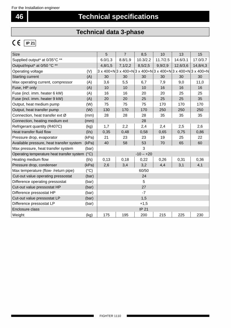
Technical specifications
FIGHTER 1110
For the Installation engineer
46
IP 21
Technical data 3-phase
Cut-out value pressostat LP (bar) 1,5
Size 5 7 8,5 10 13 15
Cut-out value pressostat HP (bar) 27
Starting current (A) 30 30 30 30 30 30
Fuse, HP only (A) 10 10 10 16 16 16
Fuse (incl. imm. heater 9 kW) (A) 20 20 25 25 25 35
Connection, heating medium ext (mm) 28
Heat transfer fluid flow (l/s) 0,35 0,48 0,58 0,65 0,75 0,86
Operating temperature heat transfer system (°C) -10 – +20
Pressure drop, condenser (kPa) 2,6 3,4 3,2 4,4 3,1 4,1
Cut-out value operating pressostat (bar) 24
Output, heat transfer pump (W) 130 170 170 250 250 250
Available pressure, heat transfer system (kPa) 40 58 53 70 65 60
Operating voltage (V) 3 x 400+N 3 x 400+N 3 x 400+N 3 x 400+N 3 x 400+N 3 x 400+N
Max operating current, compressor (A) 3,6 5,5 6,7 7,9 9,0 11,0
Fuse (incl. imm. heater 6 kW) (A) 16 16 20 20 25 25
Output, heat medium pump (W) 75 75 75 170 170 170
Connection, heat transfer ext Ø (mm) 28 28 28 35 35 35
Refrigerant quantity (R407C) (kg) 1,7 2,2 2,4 2,4 2,5 2,6
Pressure drop, evaporator (kPa) 21 23 23 19 25 22
Heating medium flow (l/s) 0,13 0,18 0,22 0,26 0,31 0,36
Difference pressostat HP (bar) -7
Difference pressostat LP (bar) +1,5
Weight (kg) 175 195 200 215 225 230
Max temperature (flow- /return pipe) (°C) 60/50
Max pressure, heat transfer system (bar) 3
Difference operating pressostat (bar) 5
Supplied output* at 0/35°C ** 6.0/1.3 8.8/1.9 10.3/2.2 11.7/2.5 14.6/3.1 17.0/3.7
Output/Input* at 0/50 °C ** 4,8/1,5 7,1/2,2 8,5/2,5 9,9/2,9 12,6/3,6 14,8/4,3
Enclosure class IP 21

Technical specifications 47For the Installation engineer
FIGHTER 1110
Technical data 1-phase
IP 21
* Compressor output only.** Refers to the heat transfer fluid temperature in / heat medium temperature flow according to EN 255.*** If ETS 11 is installed, 3 x 400 V + N is required.
Difference pressostat LP (bar) +1,5
Size 4 11
Difference pressostat HP (bar) -7
Starting current (A) 42 113
Fuse, HP only (A) 16 25
Output, heat medium pump (W) 75 170
Refrigerant quantity (R407C) (kg) 1,4 2,4
Pressure drop, evaporator (kPa) 22 19
Heating medium flow (l/s) 0,10 0,31
Max temperature (flow- /return pipe) (°C) 60/50
Difference operating pressostat (bar) 5
Connection, heat transfer ext Ø (mm) 28 35
Max pressure, heat transfer system (bar) 3
Operating voltage (V) 1 x 230*** 1 x 230***
Max operating current, compressor (A) 8,0 19,0
Fuse (incl. imm. heater 6 kW) (A) 16 -
Output, heat transfer pump (W) 130 250
Connection, heating medium ext Ø (mm) 28
Heat transfer fluid flow (l/s) 0,25 0,65
Available pressure, heat transfer system (kPa) 45 70
Pressure drop, condenser (kPa) 2,7 3,1
Cut-out value pressostat LP (bar) 1,5
Enclosure class IP 21
Cut-out value operating pressostat (bar) 24
Operating temperature heat transfer system (°C) -10 – +20
Cut-out value pressostat HP (bar) 27
Supplied output* at 0/35°C ** 4.8/1.0 11.5/2.5
Output/Input * at 0/50 °C ** 3.9/1.2 10.7/3.6
Weight (kg) 170 200

Enclosed kit
FIGHTER 1110
For the Installation engineer
48
LEK
LEK
NIBE AB
Utetemperatur givare
Outdoor temperature sensor
Aussentemperatur fühler
Artikel 018764
Level vessel with safety valve
15
85
Temperature sensors with probes Particle filter
63
Outside sensor
52
Pipe for sensors. Aluminium tape
LE
K
LE
K
Insulation tape
Conex connectors

Dealing with malfunctions 49For the Installation engineer
FIGHTER 1110
Cause: Incorrect setting of the ”Curveslope” and/or”Increase/decrease heat”.
Action: Adjust the setting.
Cause: Large amount of hot water drawn off.Action: Wait until the water heater reheats.
Cause: Compressor and/or immersion heater doesnot heat up.Action: Check and replace any blown circuit and
main fuses.
Cause: Too low start temperature setting on thecontrol computer (34).
Action: Adjust the hot water setting ”HW start”, see”Available information and on-display set-tings – display 3”.
Cause: Possible earth circuit-breaker tripped.Action: Reset the earth circuit-breaker, if the earth
circuit-breaker trips repeatedly, call an elec-trician.
Cause: Compressor and immersion heater do notheat up.
Action: Check and replace any blown circuit andmain fuses.
Cause: The compressor does not start because of atoo low value set on the heating curve.
Action: Check and possibly raise the ”Increase/decrease heat” (knob on the front panel) or”Curveslope”.
Cause: The compressor standstills due to the inter-nal overheating protection tripping.
Action: Automatic resetting after cooling for a fewhours.
Cause: Possible earth circuit-breaker tripped.Action: Reset the earth circuit-breaker, if the earth
circuit-breaker trips repeatedly, call an electri-cian.
Low hot water temperature orno hot water
Low room temperature
In the event of malfunction or operating disturbances first check the points below:
NOTE! As FIGHTER 1110 can be connectedto a large number of external units
even these should be checked.
Ifthe operating disturbance cannot be rectified by means of the above a installationengineer should be called.
High room temperature

Dealing with malfunctionsFor the Installation engineer
50
FIGHTER 1110
Alarm lamp flashes and the text”HP/MS–alarm” is displayedCause: Bad circulation in the heating medium cir-cuit.Action: Check the heating medium pump (16). Open
any radiator thermostats. Check that theparticle filter is not blocked.
Once the fault cause has been rectified set switch (8)to ”0” and then to ”1”.If the alarm lamp still flashes the motor cut-out hastripped due to the following causes.
Cause: Dropped phase or temporary mainsdisturbance.
Action: Check the fuses.
Cause: Overloaded compressor (27).Action: Call qualified service personnel.
Cause: Mechanical fault on the compressor (27).Action: Call qualified service personnel.
Cause: Faulty motor protection (26).Action: Call qualified service personnel.
Cause: Fine-wire fuse on the relay card has blown.Action: Replace the fuse.
Alarm lamp flashes and the text”LP–alarm” is displayedCause: Start up of a cold installationAction: Use ”Electric boiler” mode.
Cause: Bad circulation in heat transfer system due toinferior venting/low pressure or ice (if ice hasformed the heat transfer pump (35) will bewarm).
Action: Vent and top up the fluid. Wait a few hours.
Cause: Heat transfer pump (35) malfunction.Action: Check the heat transfer pump.
Cause: Lack of refrigerant or other fault in the coolingcircuit.Action: Call qualified service personnel.
Cause: Blocked evaporator due to too low antifreezeconcentration.
Action: Check the freezing point of the brine.After taking action, check, on the display, that the dif-ference between "Brine In" and "Brine Out" is 2 – 5 °Cthe compressor is then operational. (See ”Control –Information available on the display”, point 4.) Once the fault cause has been rectified set switch (8)to ”0” and then to ”1”.
Indications
NOTE! The fault status must not be repeatedlyreset, as there is a risk of overheating
the motor windings.

Dealing with malfunctions 51For the Installation engineer
FIGHTER 1110
Close the shut-off valves in heating medium system.Now open the drain valve (76). A small amount ofwater runs out, however, to fully empty the heatingmedium side requires the connector that joins theheating medium side and the connection on the heatpump ”Brine In” to be loosened a little to allow air toenter so the remaining water can run out. When theheating medium is empty the requisite service can becarried out.
When replacing the KB pump or drive side or whencleaning the pump, the shut-off valves in the heattransfer system should be closed. The hose betweenthe top of the evaporator and the KB pump is loos-ened on the evaporator. The loose hose end can nowbe bent down and emptied in a small bowl. Nowloosen the connection on ”Brine In” a little to allow airto enter so the heat pump’s heat transfer side is emp-tied completely. When the circuit is empty the requisiteservice can be carried out.
Draining, heat transfer sideDraining, heating medium side
Shut down FIGHTER 1110 by turning the switch(8) to ”0”.
Open the front cover.
Loosen the air screw with a screwdriver. Hold acloth around the screwdriver blade as a certainamount of water may run out.
Insert a screwdriver and turn the pump rotor.
Screw in the air screw.
Start FIGHTER 1110 and check whether the circu-lation pump runs.
It is usually easier to start the circulation pump withFIGHTER 1110 running, switch (8) set to ”1”. If help-ing the circulation pump to start is performed withFIGHTER 1110 running, be prepared for the screw-driver to jerk when the pump starts.
Helping the circulation pump to start
Luftningsskruv
16
LE
K
GR
UN
DFO
SType
UP
S25 -
60
130
P/N
:59526447
230V
-
HE
JS
AN
PC
;0017N
IBD
K50H
z
IP 44
TF
110
Cla
ss H
Max. 1
0bar
2.5
uF
45
0.2
065
0.3
090
0.4
0
1m(A
)P,
(W)
NOTE! The product’s serial number
should always be stated with allcorrespondence with NIBE.
689_ _ _ _ _ _ _ _ _ _ _
Venting screw

FIGHTER 1110
52


NIBE ABSWEDEN
R
Tel: +46 - (0)433 - 73 000Fax: +46 - (0)433 - 73 190www.nibe.com
Box 14Järnvägsgatan 40SE-285 21 MARKARYD