r iva 5 3 /6 7 in set c o n vecto r fire - goto gas docs 53-67... · flue check pass fail 1. flue...
TRANSCRIPT

Riva 53/67 Inset Convector Fire
Conventional Flue
Instructions for Use,Installation and ServicingFor use in GB, IE (Great Britain and Eire)
PR0635 Issue 13 (April 2007)
IMPORTANTDo not attempt to burn rubbish in this appliance. This appliance must only be operated with the glass door secured firmly inposition. The front casing of this appliance will become hot whilst in operation, it is therefore recommended that a suitable
guard should be used for the protection of young children, the elderly or infirm.
Please read these Instructions carefully before installation or use. Keep them in a safe place for future reference and when servicing the fire.
The commissioning sheet found at the end of the Users Sections of these instructions should be completed by the Installer.
This appliance has been certified for use in countries other than those stated. To install this appliance in these countries, it is essential to obtain thetranslated instructions and in some cases the appliance will require modification. Contact Gazco for further information.

2
PAGE
APPLIANCE COMMISSIONING CHECKLIST 3
USER INSTRUCTIONS 4
INSTALLATION INSTRUCTIONS 10
Technical Specifications 10
Site Requirements 11
Installation 14
Commissioning 22
SERVICING INSTRUCTIONS 23Servicing Requirements 23
Fault Finding 23
How to replace parts 25
Basic spare parts list 32
Service Records 33
COVERING THE FOLLOWING MODELS8590LUC P8590LUC
8596 P8596
CONTENTS

FLUE CHECK PASS FAIL
1. Flue is correct for appliance
2. Flue type (delete as appropriate) Lined Debris Kit
3. Flue flow test
4. Spillage test
GAS CHECK
1. Gas soundness & let by test
2. Standing pressure test mb
3. Appliance working pressure (on High Setting) mb
NB All other gas appliances must be operating on full
4. Gas rate m3/h
5. Does ventilation meet appliance requirements
6. Have controls been upgraded (Upgradeable models only) 8455 Standard YES NO
8456 Programmable Thermostatic and Timer YES NO
3
APPLIANCE COMMISSIONING CHECKLIST
Dealer . . . . . . . . . . . . . . . . . . . . . . . . . . . . . . . . . . . . . . . . . . . . . . . . . . . . . . . . . . . . . . . . . . . . . . .
. . . . . . . . . . . . . . . . . . . . . . . . . . . . . . . . . . . . . . . . . . . . . . . . . . . . . . . . . . . . . . . . . . . . . . . . . . . . . . . .
. . . . . . . . . . . . . . . . . . . . . . . . . . . . . . . . . . . . . . . . . . . . . . . . . . . . . . . . . . . . . . . . . . . . . . . . . . . . . . . .
Contact No. . . . . . . . . . . . . . . . . . . . . . . . . . . . . . . . . . . . . . . . . . . . . . . . . . . . . . . . . . . . . . . .
Date of Purchase. . . . . . . . . . . . . . . . . . . . . . . . . . . . . . . . . . . . . . . . . . . . . . . . . . . . . . . .
Model No. . . . . . . . . . . . . . . . . . . . . . . . . . . . . . . . . . . . . . . . . . . . . . . . . . . . . . . . . . . . . . . . . .
Serial No. . . . . . . . . . . . . . . . . . . . . . . . . . . . . . . . . . . . . . . . . . . . . . . . . . . . . . . . . . . . . . . . . . .
Gas Type . . . . . . . . . . . . . . . . . . . . . . . . . . . . . . . . . . . . . . . . . . . . . . . . . . . . . . . . . . . . . . . . . . .
Installation Company. . . . . . . . . . . . . . . . . . . . . . . . . . . . . . . . . . . . . . . . . . . . . . . . . .
. . . . . . . . . . . . . . . . . . . . . . . . . . . . . . . . . . . . . . . . . . . . . . . . . . . . . . . . . . . . . . . . . . . . . . . . . . . . . . . . .
. . . . . . . . . . . . . . . . . . . . . . . . . . . . . . . . . . . . . . . . . . . . . . . . . . . . . . . . . . . . . . . . . . . . . . . . . . . . . . . . .
Engineer . . . . . . . . . . . . . . . . . . . . . . . . . . . . . . . . . . . . . . . . . . . . . . . . . . . . . . . . . . . . . . . . . . . .
Contact No.. . . . . . . . . . . . . . . . . . . . . . . . . . . . . . . . . . . . . . . . . . . . . . . . . . . . . . . . . . . . . . . .
Corgi Reg No.. . . . . . . . . . . . . . . . . . . . . . . . . . . . . . . . . . . . . . . . . . . . . . . . . . . . . . . . . . . . .
Date of Installation . . . . . . . . . . . . . . . . . . . . . . . . . . . . . . . . . . . . . . . . . . . . . . . . . . . . .
IMPORTANT NOTICEExplain the operation of the appliance to the end user, hand the completed instructions to them for safe keeping,
as the information will be required when making any guaranteed claims.
DEALER AND INSTALLER INFORMATION
This product is guaranteed for 2 years from the date of installation, as set out in the terms and conditions of sale between Gazco and yourlocal Gazco dealer. This guarantee will be invalid, to the extent permitted by law, if the above Appliance Commissioning Checklist isnot fully completed by the installer and available for inspection by a Gazco engineer. The guarantee will only be valid during thesecond year, to the extent permitted by law, if the annual service recommended in the Instructions for Use has been completed by aCorgi registered engineer, and a copy of the service visit report is available for inspection by a Gazco engineer.

4
USER INSTRUCTIONS
1.1 A competent person must carry out installation andservicing.
1.2 In all correspondence, please quote the appliancetype and serial number, which can be found on thedatabadge located on a plate under the appliance.
1.3 Ensure that curtains are not positioned above the applianceand there is at least 300mm between the sides of theappliance and any curtains.
1.4 If any cracks appear in the glass panel do not use theappliance until the panel has been replaced.
1.5 This product is guaranteed for 2 years from the date ofinstallation, as set out in the terms and conditions of salebetween Gazco and your local Gazco dealer. Please consultyour local Gazco dealer if you have any questions. In allcorrespondence always quote the Model Number andSerial Number.
2.1 Locate the control valve on the appliance. There are twocontrol knobs on the valve, the right-hand knob controls thepilot ignition and the left-hand knob controls the mainburner.
2.2 If your appliance has already been upgraded to batteryremote control, please refer to the instructions providedwith the upgrade to operate the remote control. Thefollowing instructions will work for either situation.
2.3 Ensure that the left-hand control knob is pointing to off ( ).2.4 Ensure that the right-hand control knob is pointing to off ( ).2.5 Press in the right-hand control knob and rotate it anti-
clockwise until a click is heard (keep pressing in) and theknob is pointing to pilot ( ). The pilot should now light. Ifthe pilot has not lit, repeat the procedure until it does.
2.6 Keep the control knob pressed for 10 seconds and thenrelease it, the pilot should stay alight. If the pilot goes out,repeat the procedures until it does.
2.7 If the pilot will not light after repeated attempts, contact theretailer or installer from whom the appliance waspurchased.
2.8 Turn the right-hand control to point to main burner ( ).The appliance can now be controlled using the left-handcontrol knob.
1
AR0914
2. LIGHTING THE RIVA
1. GENERAL2.9 Turn the left-hand control knob to point to low fire ( ),
the main burner will light on low. The burner can now becontrolled between low and high settings. Turn the controlknob anticlockwise to increase the flame height andclockwise to decrease the flame height.THE YELLOW FLAMES WILL APPEAR WHEN THE FIRE HASGAINED SUFFICIENT HEAT - TYPICALLY 10 TO 20 MINUTES.
3.1 To turn the Riva off, locate the control valve, turn the left-hand control knob until it points to off ( ). The mainburner will go out leaving the pilot burning.
3.2 To turn the pilot off, locate the control valve, turn the right-hand control knob until it points to off ( ), the pilot will goout.IF THE FIRE IS EXTINGUISHED OR GOES OUT IN USE,WAIT 3 MINUTES BEFORE ATTEMPTING TO RELIGHTTHE FIRE. THE CONTROL VALVE HAS AN INTERLOCKDEVICE AND THEREFORE CANNOT BE LIT UNTIL THE 3MINUTES HAVE ELAPSED.
4.1 Your Riva is fitted with a control valve that can easily beupgraded to battery powered remote control. This upgradecan be fitted by anyone capable of simple DIY jobs andrequires no special training. There are two versions of thiscontrol which can be obtained through your local Gazcostockist.
4.2 STANDARD REMOTE CONTROL This remote control cancontrol the gas appliance after the pilot has been lit. It canturn the main burner on and regulate it from low through tohigh and back again. It can turn the main burner off leavingthe pilot burning. GAZCO PART NUMBER 8455.
4.3 PROGRAMMABLE THERMOSTATIC AND TIMER REMOTECONTROL This remote control can control the gasappliance after the pilot has been lit. In ‘MANUAL MODE’it can be used to turn the main burner on and manuallyregulate it from low through to high and back again. It canalso be used to turn the main burner off leaving the pilotburning. In ‘AUTO MODE’ it will automatically regulate theroom temperature to a pre-set temperature. In ‘TIMERMODE’ it will turn the fire on and off according to a pre-setprogramme and automatically regulate the roomtemperature during the two on periods. GAZCO PARTNUMBER 8456.
4. UPGRADING YOUR RIVA
3. TURNING THE RIVA OFF
5
USER INSTRUCTIONS
ADVICE ON HANDLING AND DISPOSAL OF FIRE CERAMICS
The fuel effect and side panels in this appliance are made fromRefractory Ceramic Fibre (RCF), a material which is commonlyused for this application.Protective clothing is not required when handling these articles,but we recommend you follow normal hygiene rules of notsmoking, eating or drinking in the work area and always wash yourhands before eating or drinking. To ensure that the release of RCF fibres are kept to a minimum,during installation and servicing a HEPA filtered vacuum isrecommended to remove any dust accumulated in and around theappliance before and after working on it. When servicing theappliance it is recommended that the replaced items are notbroken up, but are sealed within heavy duty polythene bags andlabelled as RCF waste.RCF waste is classed as stable, non-reactive hazardous waste andmay be disposed of at a licensed landfill site.Excessive exposure to these materials may cause temporaryirritation to eyes, skin and respiratory tract; wash hands thoroughlyafter handling the material.
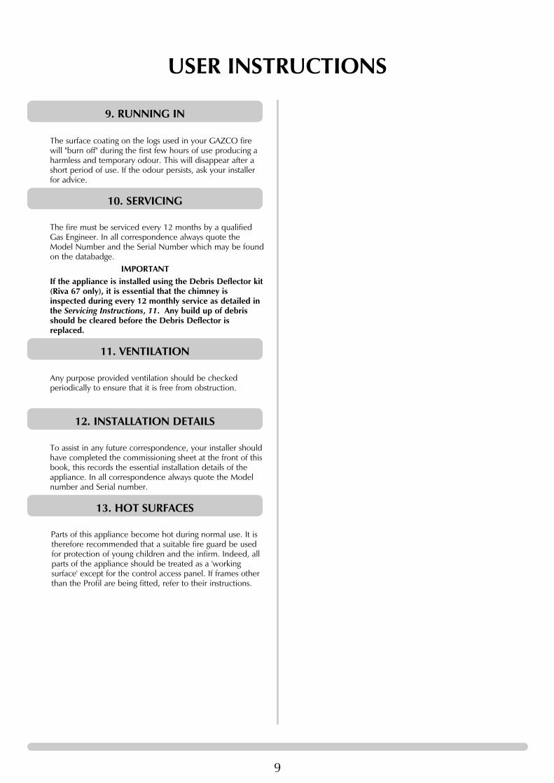
5.1 Remove the Profil frame from the appliance by removingthe 2 concealed screws behind the lower access door. Seediagram 2. Pull the frame forward at the bottom then liftclear of the top fixing lugs.
Note: If the appliance is fitted with an alternative GazcoRiva front, please refer to the separate leaflet suppliedwith the front.
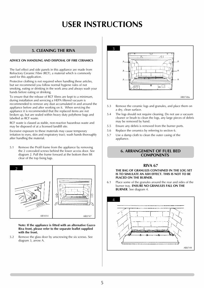
5.2 Remove the glass door by unscrewing the six screws. Seediagram 3, arrow A.
2
AR1014 AR0747
5. CLEANING THE RIVA
5.3 Remove the ceramic logs and granules, and place them ona dry, clean surface.
5.4 The logs should not require cleaning. Do not use a vacuumcleaner or brush to clean the logs, any large pieces of debrismay be removed by hand.
5.5 Ensure any debris is removed from the burner ports. 5.6 Replace the ceramics by referring to section 6.5.7 Use a damp cloth to clean the outer casing of the
appliance.
RIVA 67THE BAG OF GRANULES CONTAINED IN THE LOG SETIS TO SIMULATE AN ASH EFFECT. THIS IS NOT TO BEPLACED ON THE BURNER.
6.1 Place some of the granules around the rear and sides of theburner tray. ENSURE NO GRANULES FALL ON THEBURNER. See diagram 4.
4
AR0749
6. ARRANGEMENT OF FUEL BEDCOMPONENTS
3
AR0748a

6
USER INSTRUCTIONS6.2 Place log 1 (large black log) on the burner. Ensure the rear
of the log touches the rear of the burner. See diagram 5.
CENTRALISE THE LOG BETWEEN THE BURNER PORTSAT EITHER END.ALL THE REMAINING LOGS EXCEPT FOR THE SMALLESTONE HAVE LOCATION HOLES ON THE UNDERSIDE, THESELOCATE ON THE STUDS AT THE FRONT OF THE FIRE.
6.3 Place log 2 on the centre and locate the rear of the log onthe large flat area of log 1. See diagram 6.
6.4 Place log 3 on the far left-hand stud. The recess on theunderside of the log should locate on the top of log 1 onthe far left-hand side. See diagram 7.
7
AR0752
6
AR0751
5
AR0750
6.5 Place log 4 on the right-hand side of the centre log. There isa large recess on the underside of the log, which is locatedon log 1. See diagram 8.
6.6 Place log 5 on top of log 4 and ensure the two largelocations engage. Locate the front of the log on to the farright-hand stud. See diagram 9.
6.7 Place log 6 on the remaining stud and lean the log on to log1 between logs 2 and 3. There is a notch to locate the log.See diagram 10.
10
AR0755
9
AR0754
8
AR0753

7
USER INSTRUCTIONS6.8 Place log 7 at the front of the fire between logs 4 and 5.
DO NOT PLACE THIS LOG ON THE BURNER. IT ISONLY TO FILL THE GAP BETWEEN LOGS 4 AND 5. Thecharred effect should face the rear of the fire.Place the remaining granules between the logs so that theycover the front metal ledge. See diagram 11.ENSURE NO GRANULES FALL ON THE BURNER.
RIVA 536.9 Place log A on to the burner. Ensure the rear of the log
touches the rear burner. See diagram 12.
CENTRALISE THE LOG BETWEEN THE BURNER PORTS AT EITHER END.Four of the remaining logs have location holes on the underside. These locate on the studs at the front of the fire
12
AR1193
11
AR0756
6.10 Place log D on the third stud from the left and resting at therear on log A. See diagram 13.
6.11 Place log C on the second stud resting at the rear on log A. See diagram 14.
6.12 Place log B on the first stud. The recess on the underside of the log should locate on the top of log C. See diagram 15
15
AR1196
14
AR1195
13
AR1194

8
USER INSTRUCTIONS6.13 Place log E on the last stud. The recess on the underside of
the log should locate on to the top of log D. See diagram 16.
6.14 Place log F on the rear tray and leaning forward to locate inthe recess in log E. See diagram 17.
6.15 Place log G at the front of the fire between logs D and E.DO NOT PLACE THIS LOG ON THE BURNER. IT IS ONLYTO FILL THE GAP BETWEEN LOGS D AND E. The charredeffect should face the rear of the fire. See diagram 18.
6.16 With the granules fill the front compartment around the logs evenly. ENSURE NO GRANULES FALL ON THE BURNER. See diagram 19.
18
AR1199
17
AR1198
16
AR11976.17 NOTE: ENSURE THAT THE LOGS ARE POSITIONED AS
ABOVE. ONLY USE THE CORRECT AMOUNT OF LOGSAS SPECIFIED IN THE DIAGRAMS.
6.18 Ensure that the fibreglass seal on the back of the glass frameis intact then hook the location tabs over the hooks on thetop of the firebox. Replace the six screws working from thetop down. Tighten the screws evenly. DO NOT OVERTIGHTEN.NEVER OPERATE THE APPLIANCE WHEN THE GLASSPANEL IS REMOVED OR BROKEN.
6.19 Replace the Profil frame by hooking the top over thelocation lugs on top of the flanges, replace the two fixingscrews. See diagram 2, section 5 'Cleaning the Riva'.Note: If the appliance is fitted with an alternative GazcoRiva front, please refer to the separate leaflet supplied withthe front.
The appliance is fitted with an oxygen sensitive pilot systemthat will act to cut off the gas supply to the fire should theoxygen in the room fall below its normal level. If the fire isturned off by this device it usually indicates that there is aproblem with the flue system, this should be inspected by aqualified engineer.DO NOT ATTEMPT TO USE THE FIRE UNTIL ANENGINEER SAYS IT IS SAFE TO DO SO.THIS DEVICE IS NOT A SUBSTITUTE FOR ANINDEPENDENTLY MOUNTED CARBON MONOXIDEDETECTOR.
This is a safety feature incorporated on this appliance whichautomatically switches off the gas supply if the pilot goesout and fails to heat the thermocouple.
8. FLAME FAILURE DEVICE
7. OXYGEN DEPLETION SENSOR
19
AR1120
9
USER INSTRUCTIONS
The surface coating on the logs used in your GAZCO firewill "burn off" during the first few hours of use producing aharmless and temporary odour. This will disappear after ashort period of use. If the odour persists, ask your installerfor advice.
The fire must be serviced every 12 months by a qualifiedGas Engineer. In all correspondence always quote theModel Number and the Serial Number which may be foundon the databadge.
IMPORTANTIf the appliance is installed using the Debris Deflector kit(Riva 67 only), it is essential that the chimney isinspected during every 12 monthly service as detailed inthe Servicing Instructions, 11. Any build up of debrisshould be cleared before the Debris Deflector isreplaced.
Any purpose provided ventilation should be checkedperiodically to ensure that it is free from obstruction.
To assist in any future correspondence, your installer shouldhave completed the commissioning sheet at the front of thisbook, this records the essential installation details of theappliance. In all correspondence always quote the Modelnumber and Serial number.
Parts of this appliance become hot during normal use. It istherefore recommended that a suitable fire guard be usedfor protection of young children and the infirm. Indeed, allparts of the appliance should be treated as a 'workingsurface' except for the control access panel. If frames otherthan the Profil are being fitted, refer to their instructions.
13. HOT SURFACES
12. INSTALLATION DETAILS
11. VENTILATION
10. SERVICING
9. RUNNING IN

10
INSTALLATION INSTRUCTIONSTECHNICAL SPECIFICATION
COVERING THE FOLLOWING MODELS
MODELGAS
GAS TYPE PRESSURE AERATION INJECTORGAS RATE INPUT Kw
COUNTRYCAT. m3/h
Riva 53 I2HNatural Gas
20 mbar 8mm x 15mm 390 0.6486.8 3.0
GB, IE8596 G20 GROSS GROSS
HIGH LOW
Riva 53P8596
Riva 67P8590LUC
Riva 678590LUC
LPG PropaneG31
Natural GasG20
LPG PropaneG31
185 0.248
0.252
6.6GROSS
3.0GROSS
6.8GROSS
3.25GROSS
6.7GROSS
3.25GROSS
GB, IE
GB, IE
GB, IE
16 x 23
BLANK 16 x 23
ø5.0mm37 mbar
20 mbar 400 0.648
185
16mm x 12mm
37 mbar
I3P
I2H
I3P
Efficiency Class II
Flue Outlet Size 127mm (5") Ø
Gas Inlet Connection Size 8mm Ø
Minimum flue specification T260 / N2 / O / D / 1
Maximum flue temperature 235°C
RIVA 53PACKING CHECKLIST
Qty Description
1 Cassette and burner assembly1 Decorative frame (if supplied)1 Ceramic back panel*1 Ceramic LH side panel*1 Ceramic RH side panel*1 Log set (7 logs)1 Bag of granules
1 Fixing kit containing:1 Instruction manual4 Woodscrews4 Rawlplugs1 Self adhesive foam strip
*Fitted in appliance
NOTE: All dimensions refer to the Riva when fitted with theProfil front.
Please refer to the separate Installation leaflet supplied withany alternative Gazco Riva front for applicable dimensions.
Optional Kits• Debris Deflector (Riva 67 only) 8736• Convection fan kit 8571• Warm air ducting kit 8572
RIVA 67

11
INSTALLATION INSTRUCTIONSSITE REQUIREMENTS
WHEN INSTALLING A FLUE SYSTEM PLEASE REFER TOTHE MANUFACTURERS INSTRUCTIONS.Due to the recent changes to European chimney standards,new flue’s and chimney’s are now described by theirtemperature, pressure and resistance to corrosion,condensation and fire. To assist in identifying the correctflue system, the minimum flue specification is shown in theTechnical Specification. Existing chimneys are not coveredby this system.
1.1 The chimney or flue system must comply with the rules inforce, and must be 127mm (5") in diameter. Suitablesystems are:
1.1.1 Within an existing masonry fire place and chimney:a) Flexible liner which must be continuous from the
appliance spigot to the roof terminal.b) Gazco Debris Deflector kit (Riva 67 only)UNDER NO CIRCUMSTANCES MUST THE DEBRISDEFLECTOR KIT BE USED WITH ANY INSTALLATIONOTHER THAN AN EXISTING MASONRY CHIMNEYWHICH HAS A MINIMUM DIAMETER OF 178mm (7”).THE CHIMNEY MUST BE SOUND AND CLEAN. IFPREVIOUSLY USED FOR SOLID FUEL, IT MUST BESWEPT PRIOR TO PROCEEDING WITH THEINSTALLATION.NOTE: If the Debris Deflector kit is to be used, due careshould be taken to prevent condensation forming in thechimney. Do not fit the Debris Deflector kit if thechimney is taller than 10 metres (external wall) or 12metres (internal wall).
1.1.2 Within a false chimney breast:a) Single or twin wall rigid flue pipe.
1.2 The minimum effective height of the flue must be 3 metres(10ft).
1.3 The flue must be free from any obstruction.Any damper plates should be removed or secured in thefully open position and no restrictor plates should be fitted.
1.4 The chimney should be swept immediately prior to theinstallation of the appliance. However, where it can be seenthat the chimney is clean and unobstructed throughout itsentire length, it need not be swept.
1.5 The Riva 53 is supplied with a flue fixing plate which allowsthe flue to be attached to the appliance within the aperture.See diagram 1.
1. FLUE AND CHIMNEY REQUIREMENTS
NOTE: If it is intended to install the Riva 53 into anexisting masonry fireplace, a 5" (127mm) liner MUST beused.
1.6 The Riva 67 is designed so that the internal parts can beremoved from the outer casing to make installation easier.This allows the liner or Debris Deflector to be connectedand positioned within the chimney after the outer skin hasbeen installed.
2.1 Before installation, ensure that the local distributionconditions (identification of the type of gas and pressure)and the adjustment of the appliance are compatible.
2.2 Ensure that the gas supply is capable of delivering therequired amount of gas and is in accordance with the rulesin force.
2.3 Soft copper tubing can be used to install the appliance. Softsoldered joints can be used externally of the appliance butmust be restricted to the area shown in diagram 3.
2. GAS SUPPLY
2
AR1724 + 1724a
Debris Deflector Flexible or rigid liner
RIVA 67
1
AR1010
RIVA 53
12
INSTALLATION INSTRUCTIONSSITE REQUIREMENTS
2.4 This appliance is supplied complete with a factory fittedisolation device incorporated into the inlet connection, nofurther isolation device is required.
2.5 All supply gas pipes must be purged of any debris that mayhave entered, prior to connection to the appliance.
2.6 The gas supply enters through the silicone panel located onthe RH side of the outer box; this will need to be slit with asharp knife prior to passing the supply pipe through.
3.1 This appliance has a rated input below 7Kw and thereforedoes not normally require any additional ventilation.PLEASE REFER TO LOCAL AND NATIONAL CODES OFPRACTICE FOR VENTILATION REQUIREMENTS.
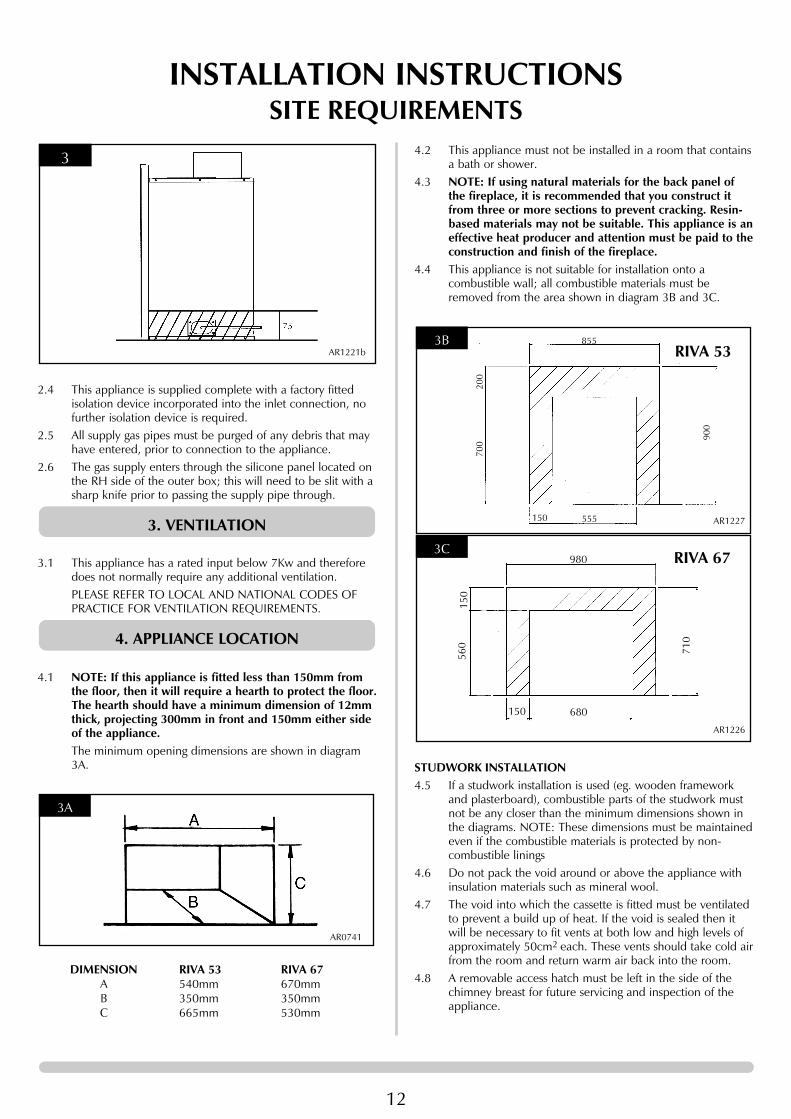
4.1 NOTE: If this appliance is fitted less than 150mm fromthe floor, then it will require a hearth to protect the floor.The hearth should have a minimum dimension of 12mmthick, projecting 300mm in front and 150mm either sideof the appliance.The minimum opening dimensions are shown in diagram3A.
DIMENSION RIVA 53 RIVA 67A 540mm 670mmB 350mm 350mmC 665mm 530mm
3A
AR0741
4. APPLIANCE LOCATION
3. VENTILATION
3
AR1221b
4.2 This appliance must not be installed in a room that containsa bath or shower.
4.3 NOTE: If using natural materials for the back panel ofthe fireplace, it is recommended that you construct itfrom three or more sections to prevent cracking. Resin-based materials may not be suitable. This appliance is aneffective heat producer and attention must be paid to theconstruction and finish of the fireplace.
4.4 This appliance is not suitable for installation onto acombustible wall; all combustible materials must beremoved from the area shown in diagram 3B and 3C.
STUDWORK INSTALLATION4.5 If a studwork installation is used (eg. wooden framework
and plasterboard), combustible parts of the studwork mustnot be any closer than the minimum dimensions shown inthe diagrams. NOTE: These dimensions must be maintainedeven if the combustible materials is protected by non-combustible linings
4.6 Do not pack the void around or above the appliance withinsulation materials such as mineral wool.
4.7 The void into which the cassette is fitted must be ventilatedto prevent a build up of heat. If the void is sealed then itwill be necessary to fit vents at both low and high levels ofapproximately 50cm2 each. These vents should take cold airfrom the room and return warm air back into the room.
4.8 A removable access hatch must be left in the side of thechimney breast for future servicing and inspection of theappliance.
3C RIVA 67980
680150
560
150
710
AR1226
3BRIVA 53
855
555150
700
200
900
AR1227

13
INSTALLATION INSTRUCTIONSSITE REQUIREMENTS
4.9 Build the studwork chimney breast to the desired size.Ensure that the clearances to combustible materials ismaintained.
NOTE: THERE IS AN OPTIONAL CONVECTION FAN KIT AVAILABLE (GAZCO PART NUMBER 8571). THIS CAN BE FITTED EITHER DURING OR AFTER INSTALLATION BUT PROVISION FOR A POWER SUPPLY MUSTBE MADE PRIOR TO INSTALLATION OF THE APPLIANCE. ALSOTHERE IS A DUCT KIT (GAZCO PART NUMBER 8572) WHICHMUST BE INSTALLED AT THE SAME TIME AS THE APPLIANCEINSTALLATION.
4B
Riva 67
MINIMUMCOMBUSTIBLE MATERIAL
CLEARANCES FOR RIVA 67
4ARiva 53
MINIMUMCOMBUSTIBLE MATERIAL
CLEARANCES FOR RIVA 53
It is recommended that a marble slip or similar material is usedwhen fitting cassette fireplaces into a plastered surface, in order toallow for heat dissipation. Also allow adequate time for newlyplastered areas to dry out. Rapid drying can create cracks. If indoubt, seek the advice of a professional plasterer.
Parts of this appliance become hot during normal use. It istherefore recommended that a suitable fire guard be used forprotection of young children and the infirm.
14
INSTALLATION INSTRUCTIONSINSTALLATION
IMPORTANT: ENSURE THAT THE APPLIANCE ISCORRECTLY ADJUSTED FOR THE GAS TYPE ANDCATEGORY APPLICABLE IN THE COUNTRY OF USE.REFER TO DATABADGE AND TECHNICALSPECIFICATIONS ON PAGE 12.
FOR DETAILS OF CHANGING BETWEEN GAS TYPESREFER TO THE SERVICING SECTION.
1.1 This appliance is fitted with a control valve that can beeasily upgraded to battery powered remote control. Thereare two versions of this control which can be obtainedthrough your local Gazco stockist.
1.2 This upgrade can be fitted before or after installation. Fullinstructions are included with the kit.
1.3 STANDARD REMOTE CONTROL This remote control cancontrol the gas appliance after the pilot has been lit. It canturn the main burner on and regulate it from low through tohigh and back again. It can turn the main burner off leavingthe pilot burning. GAZCO PART NUMBER 8455.
1.4 THERMOSTATIC AND TIMER REMOTE CONTROL Thisremote control can control the gas appliance after the pilothas been lit. In ‘MANUAL MODE’ it can be used to turn themain burner on and manually regulate it from low throughto high and back again. It can also be used to turn the mainburner off leaving the pilot burning. In ‘AUTO MODE’ itwill automatically regulate the room temperature. In ‘TIMERMODE’ it will turn the appliance on and off according to apre-set programme and automatically regulate the roomtemperature during two on periods. GAZCO PARTNUMBER 8456.
2.1 This appliance must be installed in accordance with therules in force, and used only in a sufficiently ventilatedspace. Please read these instructions fully before installationand use.
2.2 These instructions must be left intact with the user.2.3 Do not attempt to burn rubbish on this appliance.2.4 In your own interest, and those of safety, this appliance
must be installed by competent persons in accordance withlocal and national codes of practice. Failure to install theappliance correctly could lead to prosecution.
2.5 Keep all plastic bags away from young children.2.6 Do not place any object on or near to the appliance.2.7 The appliance is fitted with an oxygen sensitive pilot that
will act to cut off the gas supply to the appliance in theevent of incorrect operation of the flue. If the system acts toshut off the gas supply, this indicates that there isinsufficient flue pull. Continued operation of this safetydevice means that there may be a serious problem with theflue system, and this should be inspected by a qualified gasengineer. Do not use the appliance until an engineer saysit is safe to do so.
2. SAFETY PRECAUTIONS
1. CONTROL UPGRADE
The oxygen sensitive pilot must not be tampered with. Useonly genuine Gazco replacement parts when servicing theappliance - refer to Servicing section.
3.1 Remove the appliance from the carton and discard allunnecessary packaging. Ensure no components are thrownaway when unpacking.
3.2 If you have purchased a Profil decorative front, this will belocated inside the cardboard fitment situated in front of theRiva cassette. Remove from packaging and place to oneside until required.
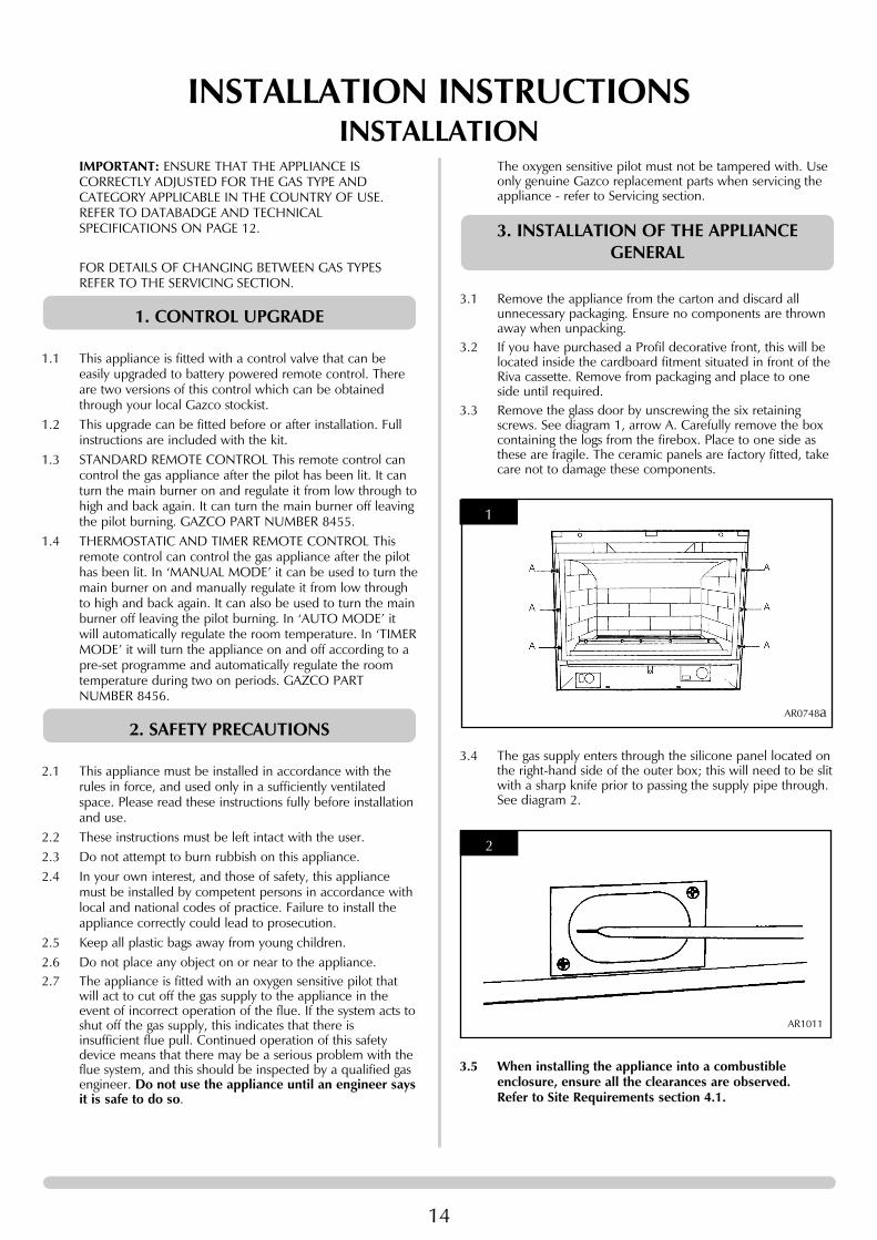
3.3 Remove the glass door by unscrewing the six retainingscrews. See diagram 1, arrow A. Carefully remove the boxcontaining the logs from the firebox. Place to one side asthese are fragile. The ceramic panels are factory fitted, takecare not to damage these components.
3.4 The gas supply enters through the silicone panel located onthe right-hand side of the outer box; this will need to be slitwith a sharp knife prior to passing the supply pipe through.See diagram 2.
3.5 When installing the appliance into a combustibleenclosure, ensure all the clearances are observed.Refer to Site Requirements section 4.1.
2
AR1011
1
AR0748a
3. INSTALLATION OF THE APPLIANCEGENERAL

15
INSTALLATION INSTRUCTIONSINSTALLATION
4.1 The flue spigot on this appliance is suitable for connectionto a 5" (127mm) flexible flue liner or rigid flue pipe. If aliner is to be used, detach the sliding flue connector fromthe top of the appliance by removing the 2 screws locatedon the front flange. See diagram 3.
4.2 Locate the flue liner in position and place the flue securingclip over the liner, push the end of the liner over theoutside of the spigot and secure by tightening the securingclip. See diagram 3.
4.3 Place the liner in its final position ensuring that the slidingflue plate rests at the correct height in the opening, and thatthe front flange of the plate rests against the outside face atthe top of the opening.
4.4 Check the pull of the flue system by applying a lightedsmoke pellet to the flue system opening. If there is adefinite flow into the chimney, proceed with theinstallation, if not; warm the chimney for a few minutes.IF THERE IS STILL NO DEFINITE FLOW, THE FLUE MAYREQUIRE ATTENTION - SEEK EXPERT ADVICE.
4.5 Remove the backing paper from the silicone foam stripsupplied in the fixing kit and fix to the back of the outerflanges of the appliance, ensure that it is located below theframe location lugs on the top flange.
4.6 Feed gas supply through right-hand side of the appliance.See Diagram 2. Locate the edges of the sliding flue plate inthe runners located on top of the outer box and slide theappliance backwards into the opening ensuring that thesliding plate fully locates in the runners, secure in place withthe 2 previously removed screws. See diagram 3.
4.7 Remove the compression elbow from the appliance andconnect it to the gas supply pipe. As the appliance islocated into the enclosure pass the elbow and supply pipethrough the silicone panel on the right-hand side. PURGETHE SUPPLY PIPE. This is essential to expel any debris thatmay block the gas controls. Connect the elbow to theappliance inlet pipe. See diagram 4.
3
AR1010
4. INSTALLATION OF RIVA 53
4.8 Secure the appliance through the four fixing holes using thescrews provided. See diagram 5, arrow B.
5.1 When installing the appliance into a combustibleenclosure, ensure all the clearances are observed.Refer to Site Requirements section 4.1.
5.2 The flue spigot on this appliance is suitable for connectionto a 5” (127mm) flexible flue liner or rigid flue pipe.Alternatively, it can be fitted to the optional Gazco DebrisDeflector. This removes the need for a flue liner.
Note: Ensure that the flue is not subject to condensation, see1.1
5.3 If a liner or the Debris Deflector is being fitted proceed asfollows:
5.4 Remove the ceramic panels and log support as detailed inSection 2 of the Servicing Instructions. Remove the burnermodule and place safely to one side.
5.5 Remove the four screws securing the inner to the outer boxand undo the two screws behind the rear ceramic panel.Diagram 6.
5. INSTALLATION OF RIVA 67
5
AR0748B
4
AR1013

16
INSTALLATION INSTRUCTIONSINSTALLATION
5.6 Slide the inner box away from the outer box by pulling itforward. Diagram 7
5.7 Remove the backing paper from the silicone foam stripsupplied in the fixing kit and fix to the back of the outerflanges of the appliance, ensure that it is located below theframe location lugs on the top flange.
5.8 Feed the gas supply through the right-hand side of the outerbox, see Diagram 2, and slide the outer box backwardsuntil its outer flange sits neatly onto the wall. Secure theouter box through the four fixing holes using the screwsprovided. Diagram 8.
8
AR1730
7
AR1725
6
AR1727
5.9 Flexible Liner5.9.1 Remove the eight screws on the spigot plate, Diagram 9.
5.9.2 Pull the liner through the hole in the top of the outer boxand attach it to the flue spigot plate using the clip provided.Tighten the clip securely. Diagram 10.
5.9.3 Secure the flue spigot plate to the inside top surface usingthe eight screws provided. Diagram 9.
5.10 Debris Deflector AssemblyComponents:a) Flue pipeb) End terminalc) Clipd) Warning label
5.10.1 The flue pipe is supplied with tape around each end of theflue to protect your hands from the sharp edges. You mustremove the tape before assembling the debris deflector.
5.10.2 Place clip over one end of the flue pipe and insert the EndTerminal inside of the flue pipe. Do not insert the EndTerminal past the point shown in Diagram 11.
11
AR1734
10
AR1726
9
AR1728

17
INSTALLATION INSTRUCTIONSINSTALLATION
5.10.3Tighten the clip until the End Terminal is secured firmly inplace.
5.11 Attach the Debris Deflector to the flue spigot plate using theclip provided. Tighten the clip securely. Diagram 12.
5.12 Push the Debris Deflector up into the chimney and securethe flue spigot plate to the inside top surface using the eightscrews provided. Diagram 13.
5.13 Attach the label supplied with the Debris Deflector to thebase of the appliance on the front right-hand side asshown.
14
AR1731
13
AR1724 AR1728
AR1726
12
5.14 Locate the top of the inner box into the runners at the topof the outer box. Diagram 15.
5.15 Gently slide the inner box into the outer box until the twoflanges meet. Secure with the screws on the flange and thetwo screws on the inside rear surface as shown.
5.16 Replace the burner module and secure in position. Replacethe log support and ceramic panels as detailed in Section 2of the Servicing Instructions.
5.17 PURGE THE SUPPLY PIPE. This is essential to expel anydebris that may block the gas controls. Connect the elbowto the appliance inlet pipe. See diagram 17.
17
AR1012
16
AR1727
15
AR1725a
18
INSTALLATION INSTRUCTIONSINSTALLATION
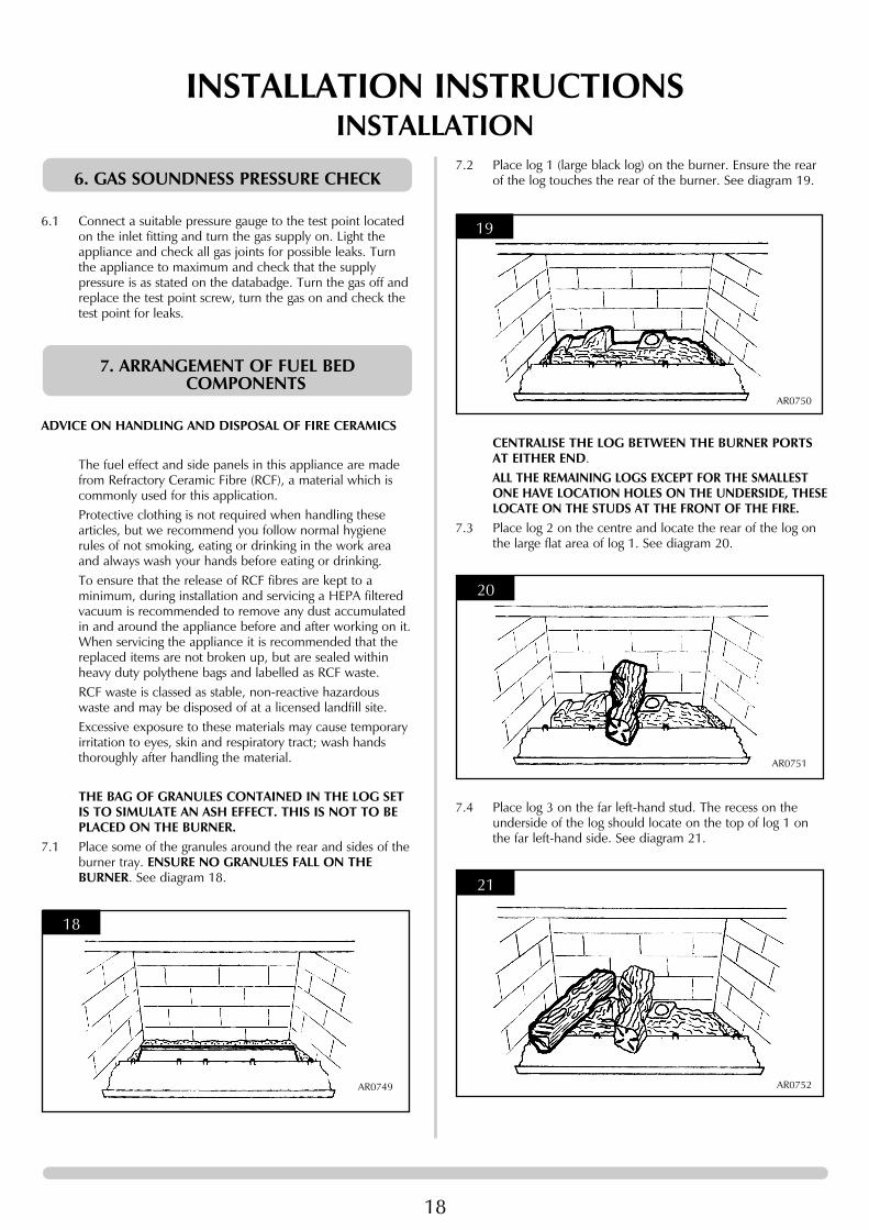
6.1 Connect a suitable pressure gauge to the test point locatedon the inlet fitting and turn the gas supply on. Light theappliance and check all gas joints for possible leaks. Turnthe appliance to maximum and check that the supplypressure is as stated on the databadge. Turn the gas off andreplace the test point screw, turn the gas on and check thetest point for leaks.
ADVICE ON HANDLING AND DISPOSAL OF FIRE CERAMICS
The fuel effect and side panels in this appliance are madefrom Refractory Ceramic Fibre (RCF), a material which iscommonly used for this application.Protective clothing is not required when handling thesearticles, but we recommend you follow normal hygienerules of not smoking, eating or drinking in the work areaand always wash your hands before eating or drinking. To ensure that the release of RCF fibres are kept to aminimum, during installation and servicing a HEPA filteredvacuum is recommended to remove any dust accumulatedin and around the appliance before and after working on it.When servicing the appliance it is recommended that thereplaced items are not broken up, but are sealed withinheavy duty polythene bags and labelled as RCF waste.RCF waste is classed as stable, non-reactive hazardouswaste and may be disposed of at a licensed landfill site.Excessive exposure to these materials may cause temporaryirritation to eyes, skin and respiratory tract; wash handsthoroughly after handling the material.
THE BAG OF GRANULES CONTAINED IN THE LOG SETIS TO SIMULATE AN ASH EFFECT. THIS IS NOT TO BEPLACED ON THE BURNER.
7.1 Place some of the granules around the rear and sides of theburner tray. ENSURE NO GRANULES FALL ON THEBURNER. See diagram 18.
18
AR0749
7. ARRANGEMENT OF FUEL BEDCOMPONENTS
6. GAS SOUNDNESS PRESSURE CHECK7.2 Place log 1 (large black log) on the burner. Ensure the rear
of the log touches the rear of the burner. See diagram 19.
CENTRALISE THE LOG BETWEEN THE BURNER PORTSAT EITHER END.ALL THE REMAINING LOGS EXCEPT FOR THE SMALLESTONE HAVE LOCATION HOLES ON THE UNDERSIDE, THESELOCATE ON THE STUDS AT THE FRONT OF THE FIRE.
7.3 Place log 2 on the centre and locate the rear of the log onthe large flat area of log 1. See diagram 20.
7.4 Place log 3 on the far left-hand stud. The recess on theunderside of the log should locate on the top of log 1 onthe far left-hand side. See diagram 21.
21
AR0752
20
AR0751
19
AR0750

19
INSTALLATION INSTRUCTIONSINSTALLATION
7.5 Place log 4 on the right-hand side of the centre log. There isa large recess on the underside of the log, which is locatedon log 1. See diagram 22.
7.6 Place log 5 on top of log 4 and ensure the two largelocations engage. Locate the front of the log on to the farright-hand stud. See diagram 23.
7.7 Place log 6 on the remaining stud and lean the log on to log1 between logs 2 and 3. There is a notch to locate the log.See diagram 24.
7.8 Place log 7 at the front of the fire between logs 4 and 5.DO NOT PLACE THIS LOG ON THE BURNER. IT IS ONLYTO FILL THE GAP BETWEEN LOGS 4 AND 5. The charredeffect should face the rear of the fire.
24
AR0755
23
AR0754
22
AR0753
Place the remaining granules between the logs so that theycover the front metal ledge. See diagram 25.ENSURE NO GRANULES FALL ON THE BURNER.
RIVA 537.9 Place log A on to the burner. Ensure the rear of the log
touches the rear burner. See diagram 26.
CENTRALISE THE LOG BETWEEN THE BURNER PORTS ATEITHER END.Four of the remaining logs have location holes on the underside. These locate on the studs at the front of the fire.
7.10 Place log D on the third stud from the left and resting at therear on log A. See diagram 27.
27
AR1194
26
AR1193
25
AR0756
20
INSTALLATION INSTRUCTIONSINSTALLATION
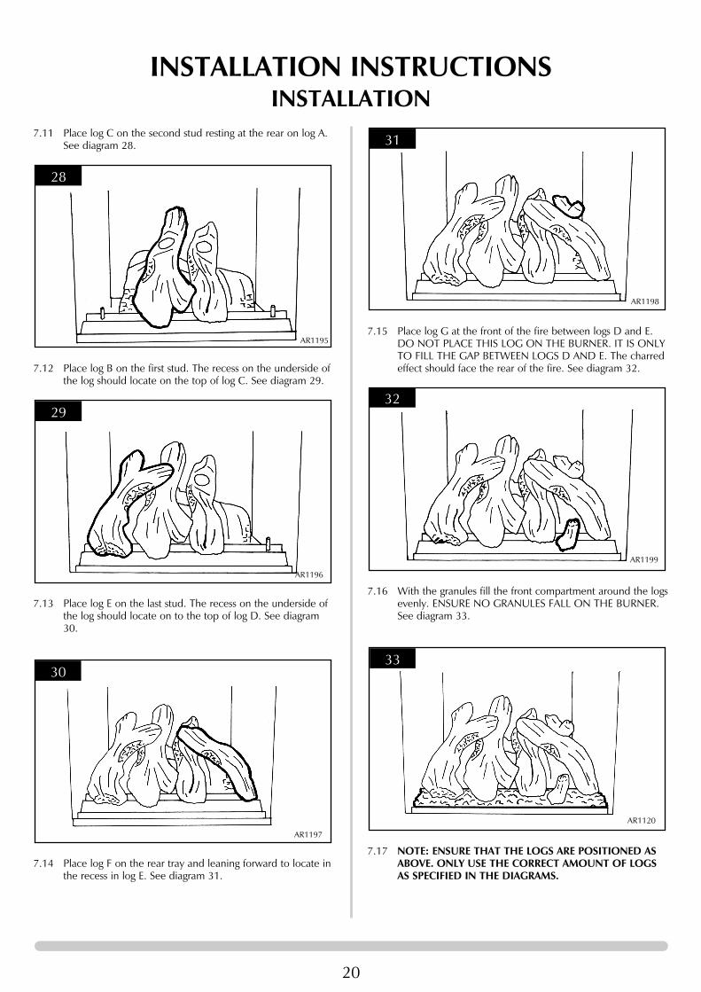
7.11 Place log C on the second stud resting at the rear on log A. See diagram 28.
7.12 Place log B on the first stud. The recess on the underside of the log should locate on the top of log C. See diagram 29.
7.13 Place log E on the last stud. The recess on the underside of the log should locate on to the top of log D. See diagram 30.
7.14 Place log F on the rear tray and leaning forward to locate inthe recess in log E. See diagram 31.
30
AR1197
29
AR1196
28
AR11957.15 Place log G at the front of the fire between logs D and E.
DO NOT PLACE THIS LOG ON THE BURNER. IT IS ONLYTO FILL THE GAP BETWEEN LOGS D AND E. The charred effect should face the rear of the fire. See diagram 32.
7.16 With the granules fill the front compartment around the logsevenly. ENSURE NO GRANULES FALL ON THE BURNER. See diagram 33.
7.17 NOTE: ENSURE THAT THE LOGS ARE POSITIONED ASABOVE. ONLY USE THE CORRECT AMOUNT OF LOGSAS SPECIFIED IN THE DIAGRAMS.
33
AR1120
32
AR1199
31
AR1198

21
INSTALLATION INSTRUCTIONSINSTALLATION
7.18 Ensure that the fibreglass seal on the back of the glass frameis intact then hook the location tabs over the hooks on thetop of the firebox. Replace the six screws working from thetop down. Tighten the screws evenly. DO NOT OVERTIGHTEN.NEVER OPERATE THE APPLIANCE WHEN THE GLASSPANEL IS REMOVED OR BROKEN.
7.19 Replace the Profil frame by hooking the top over thelocation lugs on top of the flanges, replace the two fixingscrews. See diagram 5, section 7 'Cleaning the Riva'.Note: If the appliance is fitted with an alternative GazcoRiva front, please refer to the separate leaflet supplied withthe front.
8.1 Ensure that the fibreglass seal on the back of the glass frameis intact then hook the location tabs over the hooks on thetop of the firebox. Replace the six screws working from thetop down. Tighten the screws evenly. DO NOT OVERTIGHTEN. See diagram 2, Section 5 'Cleaning the Riva'.NEVER OPERATE THE APPLIANCE WHEN THE GLASSPANEL IS REMOVED OR BROKEN.
8.2 Replace the decorative frame by hooking the top over thelocation lugs on top of the flanges, replace the two fixingscrews, see diagram 1, Section 5 'Cleaning the Riva'.NOTE: If the appliance is fitted with an alternative Gazco Rivafront, please refer to the separate leaflet supplied with the front.NOTE: ENSURE THAT THE LOGS ARE POSITIONED ASABOVE. ONLY USE THE CORRECT AMOUNT OF LOGSAS SPECIFIED IN THE DIAGRAMS.
9.1 Locate the control valve on the appliance. There are twocontrol knobs on the valve, the right-hand knob controls thepilot ignition and the left-hand knob controls the mainburner. See diagram 32.
9.2 If your appliance has already been upgraded to batteryremote control, please refer to the instructions providedwith the upgrade to operate the remote control. Thefollowing instructions will work for either situation.
9.3 Ensure that the left-hand control knob is pointing to off ( ).9.4 Ensure that the right-hand control knob is pointing to off .
AR0914
32
9. LIGHTING THE RIVA
8. FITTING THE DOOR
9.5 Press in the right-hand control knob and rotate it anti-clockwise until a click is heard (keep pressing in) and theknob is pointing to pilot ( ). The pilot should now light. Ifthe pilot has not lit, repeat the procedure until it does.
9.6 Keep the control knob pressed for 10 seconds and thenrelease it, the pilot should stay alight. If the pilot goes out,repeat the procedures until it does.
9.7 If the pilot will not light after repeated attempts, contact theretailer or installer from whom the appliance waspurchased.
9.8 Turn the right-hand control to point to main burner ( ).The appliance can now be controlled using the left-handcontrol knob.
9.9 Turn the left-hand control knob to point to low fire ( ),the main burner will light on low. The burner can now becontrolled between low and high settings. Turn the controlknob anticlockwise to increase the flame height andclockwise to decrease the flame height.THE YELLOW FLAMES WILL APPEAR WHEN THE FIRE HASGAINED SUFFICIENT HEAT - TYPICALLY 10 TO 20 MINUTES.

22
INSTALLATION INSTRUCTIONSCOMMISSIONING
1.1 Check flame picture.1.2 Check gas pressure.1.3 Close all doors and windows in the room, ignite the
appliance and operate on maximum for 5 minutes.Position a lighted smoke match just inside the draughtdiverter opening and check that all the smoke is drawn inall along the opening. If there is any doubt, run theappliance for a further 10 minutes, and repeat the test. Seediagram 1.
1.4 If there are any extractor fans in the room or adjacentrooms, the test must be repeated with the fans running onmaximum.IF SPILLAGE PERSISTS, DISCONNECT THE APPLIANCEAND SEEK EXPERT ADVICE.For future reference record the installation details on thecommissioning sheet on page 3.
1
AR0757
1. COMMISSIONING THE RIVA

23
SERVICING INSTRUCTIONSSERVICING/FAULT FINDING CHARTS
This appliance must be serviced at least once a year by acompetent person.All tests must be serviced by best practice as described by thecurrent CORGI recommendations.1.1 Before any test are undertaken on the appliance, conduct a
gas soundness test for the property to ensure that there areno gas leaks prior to starting work.
1.2 Before any tests are undertaken on the appliance it is alsorecommended to fully check the operation of theappliance.
1.3 RIVA 67 OnlyCheck if the appliance has been fitted with a DebrisDeflector as indicated on the Appliance CommissioningChecklist on page 3 and a label attached to the base of theunit. See diagram 1.
If the appliance has been fitted with this device, then it isessential to remove the appliance to check the debriscollection space immediately above the appliance inside thechimney. See Installation of Riva 67, Section 5, InstallationInstructions.
1. SERVICING REQUIREMENTS
1.4 Correct any faults found during the initial tests. Re-commission the appliance conducting the usual safetychecks.
1.5 Advise the customer of any remedial action taken.1.6 Check the seal on the inner lip of the spigot plate is intact.
Replace if necessary, see Replacing Parts, 11.
2
AR1736
1
AR1731
IGN
ITIO
N F
UN
CTI
ON
AL C
HEC
K 1
PILO
T W
ILL
NO
T LI
GH
T
Ensu
re th
ere
is no
deb
ris a
roun
d th
e pi
lot a
ssem
bly,
(e
.g. s
oot,
etc.
) whi
ch c
ould
sho
rt th
e sp
ark,
cle
an th
e ar
ea.
Ope
rate
the
valv
e.Is
ther
e a
spar
k?
Con
sult
Use
r In
stru
ctio
ns a
nd re
try.
Che
ck a
lignm
ent o
f pilo
tbu
rner
hea
d, c
hang
e th
eig
nitio
n le
ad.
See
Repl
acin
g Pa
rts, s
ectio
n 2.
Che
ck is
olat
ion
tap
and
gas
met
er, r
etry
.
Cor
rect
and
re
try.
Purg
e th
e ga
s pi
pes
and
retry
.
GO
TO
TH
E N
EXT
CH
ARG
E IG
NIT
ION
FUN
CTI
ON
AL C
HEC
K 2
SYST
EM O
K
Ther
e is
a bl
ocka
ge in
the
syst
em, c
heck
the
inle
t tes
t poi
nt,
the
mag
sea
ting
and
valv
e.
Is th
e ga
s tu
rned
on
to th
eap
plia
nce?
Is th
e ga
s pr
essu
re c
orre
ct?
Has
the
syst
em g
ot
any
air i
n it?
Doe
s th
e pi
lot l
ight
?
Is th
e co
ntro
l bei
ng
oper
ated
cor
rect
ly?
Will
the
pilo
t lig
ht
with
a m
atch
?
No
Yes
No
Yes
No
Yes
Yes
No
NoYe
s
No No
Yes
Yes

24
SERVICING INSTRUCTIONSFAULT FINDING CHARTS
PILO
T W
ILL
NO
T ST
AY L
IT O
R FI
RE G
OES
OU
T IN
USE
Ensu
re th
ere
is no
deb
ris a
roun
d th
e pi
lot a
ssem
bly,
(e
.g. s
oot e
tc.)
Che
ck fo
r flu
ff in
the
pilo
t aer
atio
n ho
le.
See
diag
ram
5 in
Rep
laci
ng P
arts
, sec
tion
2.3.
Prob
lem
is w
ith th
epi
pew
ork
or
fittin
gs w
hich
lead
to
the
fire.
Cor
rect
an
d re
try.
Is th
erm
ocou
ple
conn
ectio
n go
od
in b
ack
of v
alve
?
Repl
ace
OD
S un
it.
Will
pilo
t st
ay a
light
?
Cha
nge
mag
unit.
Is th
e pi
lot f
lam
e of
the
corr
ect l
engt
h? S
eedi
agra
m 5
in R
epla
cing
Parts
, sec
tion
2.3.
Cha
nge
the
OD
S un
it.
Will
pilo
t st
ay a
light
?W
ith th
e pi
lot
runn
ing
is th
e ga
spr
essu
re a
s st
ated
on
the
data
badg
e?
With
the
fire
runn
ing
on fu
ll is
the
gas
at
the
pres
sure
sta
ted
on th
e da
taba
dge?
Run
for 3
min
s, tu
rn o
ff, ti
me
inte
rval
until
mag
uni
t shu
tsw
ith a
clic
k. Is
this
grea
ter t
han
7se
cond
s?
Run
for 3
min
s, tu
rnof
f, tim
e in
terv
al u
ntil
mag
uni
t shu
ts w
ith a
clic
k. Is
this
grea
ter
than
7 s
econ
ds?
Tigh
ten
the
conn
ectio
n an
d re
try.
No
No
No
No
No
No
Yes
SYST
EM O
K
Yes
Yes
Yes
Yes
No
Yes
Yes
NoLigh
t the
pilo
t and
kee
p th
e co
ntro
l kno
b pu
shed
in
at le
ast 1
0 se
cond
s be
fore
letti
ng g
o.
FLAM
E FA
ILU
RE F
UN
CTI
ON
AL C
HEC
K 3
IGN
ITIO
N F
UN
CTI
ON
AL C
HEC
K 2
NO
SPA
RK
Ensu
re th
ere
is no
deb
ris a
roun
d th
e pi
lot a
ssem
bly,
(e
.g. s
oot e
tc.)
whi
ch c
ould
sho
rt th
e sp
ark,
cle
an th
e ar
ea.
Con
sult
the
user
s in
stru
ctio
ns, r
etry
.
From
Igni
tion
Faul
t Fi
ndin
g C
hart
1
Is th
e ga
p be
twee
nel
ectro
de a
nd
ther
moc
oupl
e 4.
0mm
?
Has
igni
tion
lead
be
com
e de
tach
ed o
r is
conn
ectio
n po
or?
Rem
ove
the
elec
trode
lead
fro
m e
lect
rode
with
insu
late
d pl
iers
. Hol
d th
e tip
3.5
mm
from
the
pilo
t pip
ewor
k, is
ther
e a
spar
k w
hen
the
valv
e ‘c
licks
’?
Is th
e el
ectro
de w
irede
tach
able
from
the
piez
o in
the
valv
e?
Repl
ace
the
lead
, ret
ry.
Cor
rect
and
retry
.
Che
ck fo
r def
ectiv
e or
da
mag
ed c
ontro
l kno
b sp
indl
e or
cam
ope
ratio
n. C
heck
for
corr
ect l
ocat
ion
of p
iezo
com
pone
nts.
Cor
rect
and
retry
.
Rem
ove
the
elec
trode
lead
from
the
piez
o. O
pera
te th
e va
lve.
Doe
s a
spar
k ju
mp
from
the
piez
o to
the
valv
e bo
dy?
Is th
e va
lve
bein
g op
erat
ed c
orre
ctly
?
Rese
t the
ele
ctro
de g
ap, r
etry
.
Yes
Yes
Yes
No
No
No
Yes
Yes
Yes
No N
o
Repl
ace
the
pilo
t uni
t.Re
plac
e th
e el
ectro
de
lead
and
retry
.
Yes
No

25
SERVICING INSTRUCTIONSREPLACING PARTS
1.1 All principal components can be replaced without removingthe appliance from its installation, although it is essentialthat the gas supply to the appliance is turned off at theisolation device before proceeding further.
1.2 It will be necessary to remove the complete burner modulebefore any of the components can be serviced.
1.3 If the appliance is fitted with a debris deflector (Servicing1.3), it will be necessary to remove the inner appliance toinspect the debris collection space.
2.1 To remove the module the procedure is as follows:a) Remove the decorative front, see diagram 1.(If the appliance is fitted with any front other than the Profil,please refer to the Instructions supplied with the front forremoval.)
b) Remove the glass frame. See diagram 2, arrow A.
c) Remove the ceramic logs.d) Remove the granules.e) Carefully slide the side panels forward and store safely.
(These are very fragile). See diagram 3.
2
AR0748A
1
AR1014 AR0747
2. REMOVE THE BURNER MODULE
1. GENERAL
HAVE YOU ISOLATED THE GAS SUPPLY?f) Disconnect the isolating device from the appliance inlet
pipe so as to leave the gas supply isolated.g) If the appliance has been upgraded to a remote
control, disconnect the leads from the top lefthand corner of the gas valve. See diagram 4.
h) Remove the screws retaining the log support. See diagram 5.
5
AR0758
4
AR0744
3
AR0759

26
SERVICING INSTRUCTIONSREPLACING PARTS
i) Remove the two screws at the front of the burner tray and loosen the screw at the rear. See diagram 6.
j) Hold the burner tray at the front, pull forward and rotate upwards. The unit can now be serviced.
k) When replacing the unit ensure the location tabs engage under the divider plate. See diagram 7.
3.1 With the module removed as in Servicing Instructionssection 2.1, undo the injector nut. Remove thethermocouple from the rear of the gas valve.
3.2 Remove the pilot pipe from the pilot unit and the gas valve.See diagram 8. Pull the ignition lead off the electrode. Turn
3. MAIN BURNER
5
AR0760
6
AR0767(A)
the module over and remove the four screws. See diagram9. The burner can now be removed.
3.3 To replace the burner, align the injector with the feed pipeand loosely attach the nut. Replace the four screws andtighten the injector nut. Replace the thermocouple, pilotpipe and ignition lead.
3.4 When replacing the module ensure the thermocouple, feedpipe and pilot pipe engage in the divider plate slot. Seediagram 10. Check for leaks.
10
AR0760
9
AR0767
8
AR0763

27
SERVICING INSTRUCTIONSREPLACING PARTS
4.1 Undo the compression nut on the pilot burner then undothe thermocouple at the rear of the gas valve. Carefully cutthe cable ties holding the thermocouple to the pilot pipe.Remove the HT lead from the electrode, undo the tworetaining screws and remove the pilot. See diagram 11.
4.2 When replacing the pilot ensure the thermocouple followsits original route, i.e. along the pilot pipe. Attach thethermocouple to the pipe with new cable ties.
4.3 Set the spark gap. See diagram 12.
12
AR0097
11
AR0761
4. PILOT UNIT
5.1 Gain access to the pilot assembly, (see section 2) anddisconnect the ignition lead from the electrode.
5.2 Remove the front cover from the control valve, (seediagrams 13 and 14), disconnect the other end of theignition lead from the valve body, note the existing route ofthe ignition lead.
5.3 Replace with a new ignition lead following the same routeas the old one. Replace the valve cover and the pilotassembly.
5.4 Check the operation of the new ignition lead.
6.1 The piezo assembly used on this appliance is notserviceable and is unlikely to fail.
6.2 If a new piezo is required it will be necessary to change thegas valve. Refer to Section 7.
6. PIEZO
14
AR0916
13
AR0915
5. IGNITION LEAD

SERVICING INSTRUCTIONSREPLACING PARTS
28
7.1 Remove the burner module as described in Servicingsection 2.1.
7.2 Disconnect the 2 x 8mm and 1 x 4mm gas pipe fittings atthe back of the gas valve and also disconnect thethermocouple. See diagram 15.
7.3 Undo the single screw that secures the left-hand side of thecontrol cover. See diagram 16.
7.4 To release the right-hand side of the control cover insert thenarrow blade screwdriver into the slot shown in diagram 17,lever it gently and pull from the right-hand side at the sametime. The cover will now come off, there is a smallcylindrical metal spacer inside the cover, this must be keptand replaced on the fixing screw during re-assembly.
NOTE: If this appliance has been upgraded to remotecontrol, the small metal spacer will have been replacedby a motor.
16
AR0915
15
AR0763
7. GAS VALVE
7.5 Disconnect the ignition lead from the gas valve. 7.6 Undo the two bolts securing the gas valve to the appliance
and remove the valve.7.7 Replace in reverse order.7.8 Check all joints for gas leaks, check the operation of the
thermocouple and ignition lead.
8.1 Remove the burner module as described in Servicingsection 1.4. Undo the thermocouple connection from theback of the gas valve.
8.2 Undo the mag valve retaining nut at the back of the controlvalve, gently tap out the mag valve and replace with a newunit. Replace the retaining nut and tighten. See diagram 18.
8.3 Reassemble the thermocouple into the rear of the valve.DO NOT OVERTIGHTEN. Check for leaks afterreassembly.
18
AR0763
8. MAGNETIC SAFETY VALVE
17
AR0916

29
SERVICING INSTRUCTIONSREPLACING PARTS
9.1 Remove the burner module as described in Servicingsection 2.1. Disconnect the pipe from the injector and thegas valve. See diagram 19.
9.2 Rotate the injector until it is fully removed, and install thecorrect replacement injector. Re-assemble and turn the gassupply on, check for any leaks.
NOT ALL MODELS HAVE AERATION PLATES. REFER TONOTE AT BEGINNING OF INSTALLATIONINSTRUCTIONS.
10.1 Remove the burner module as described in Servicingsection 2.1.
10.2 Remove the fixing screw and slide the plate off the venturi.10.3 Replace with the correct size plate and secure with the
screw. Ensure the lower edge of the plate is located overthe venturi flange. See diagram 20.
20
AR0766
10. PRIMARY AERATION PLATE
19
AR0763
9. MAIN INJECTOR
In order to change between gas types, it will benecessary to change the following items:
Burner UnitPilot UnitControl ValveInjectorAeration Plate (if required)Databadge
A kit of parts is available for this, always quote the Modelnumber and Serial number when ordering any spare parts.NOTE: THE CONTROL VALVE IS FACTORY PRESET FORTHE CORRECT GAS TYPE AND MODEL, A NEW UNITWILL NEED TO BE ORDERED WHEN CHANGINGBETWEEN GAS TYPES.
See Installation Instructions, section 1.
13.1 To remove the module the procedure is as follows:a) Remove the outer surround, see diagram 21.
b) Remove the glass frame. See diagram 22, arrow A.
c) Remove the ceramic logs.d) Remove the granules.e) Carefully slide the side panels forward and store safely.
(These are very fragile). See diagram 23
13. DEBRIS DEFLECTOR INSPECTION
12. CONTROL UPGRADE
11. CHANGING BETWEEN GAS TYPES
22
AR0748A
21
AR1014 AR0747

30
SERVICING INSTRUCTIONSREPLACING PARTS
HAVE YOU ISOLATED THE GAS SUPPLY?f) Disconnect the isolating device from the appliance inlet
pipe so as to leave the gas supply isolated.g) To remove the main burner:
• Undo the three screws, Diagram 24• Pull the unit out
For more detail, see Replacing Parts, Removing the BurnerModule.
h) Remove the four screws securing the inner to the outer box and undo the two screws behind the rear ceramic panel. Diagram 25.
24
AR0767B
23
AR0759
i) Slide the inner box away from the outer box by pulling itforward. Diagram 26.
j) Undo the eight screws securing the flue spigot plate to the inside top surface. See Diagram 27.
k) Pull the debris deflector down and out of the chimneyand inspect the space immediately above the appliance fora build up of debris. See Diagram 28.
27
AR1728
26
AR1725
25
AR1727

31
SERVICING INSTRUCTIONSREPLACING PARTS - RIVA 67
k) Inspect the debris deflector for damage and replace ifnecessary. Check the seal is intact, see ServicingRequirements, Section 1 and replace if necessary.
13.2 Follow these instructions in reverse order to reassemble theappliance.
28
AR1724

Component RIVA 67 RIVA 53NG LPG NG LPG
PILOT PI0044 PI0045 PI0044 PI0045INJECTOR IN0007 IN0040 IN0028 IN0040BURNER UNIT GZ3124 GZ3125 GZ4321 GZ4322AERATION PLATE Nat Gas Nat Gas
G20 G20GZ3867 GZ3966
LPG LPGG30 G31 G30 G31N/A GZ2003 GZ3865 GZ4333
GAS VALVE* GC0088MAG UNIT GC0092IGN LEAD GC0090CERAMIC LINERS BLACK RIBBED BRICK EFFECT BLACK RIBBEDREAR CERAMIC PANEL CE0345 CE0326 CE0385L/H CERAMIC PANEL CE0346 CE0327 CE0450R/H CERAMIC PANEL CE0347 CE0328 CE0450GRANULES CE0424 CE0423LOG SET CE0306 CE0415LOG 1 CE0307 CE0416LOG 2 CE0308 CE0417LOG 3 CE0309 CE0418LOG 4 CE0310 CE0419LOG 5 CE0311 CE0420LOG 6 CE0312 CE0421LOG 7 CE0313 CE0422STANDARD UPGRADE KIT 8455TIMER/THERMO. UPGRADE KIT 8456CONVECTION FAN KIT 8571DUCT KIT 8572WINDOW FRAME ASSEMBLY GZ3111 GZ4310DEBRIS DEFLECTOR KIT 8736 N/A
* Gas Valve is pre-set for the appliance
14. SHORT SPARES LIST
32
SERVICING INSTRUCTIONSREPLACING PARTS

33
SERVICE RECORDS
1ST SERVICE
Date of Service:...........................................................................
Next Service Due:.......................................................................
Signed:........................................................................................
Dealer's Stamp/CORGI Registration Number
3RD SERVICE
Date of Service:...........................................................................
Next ServiceDue:........................................................................
Signed:........................................................................................
Dealer's Stamp/CORGI Registration Number
5TH SERVICE
Date of Service:...........................................................................
Next Service Due:.......................................................................
Signed:........................................................................................
Dealer's Stamp/CORGI Registration Number
7TH SERVICE
Date of Service:...........................................................................
Next Service Due:.......................................................................
Signed:........................................................................................
Dealer's Stamp/CORGI Registration Number
9TH SERVICE
Date of Service:...........................................................................
Next Service Due:.......................................................................
Signed:........................................................................................
Dealer's Stamp/CORGI Registration Number
2ND SERVICE
Date of Service:...........................................................................
Next Service Due:.......................................................................
Signed:........................................................................................
Dealer's Stamp/CORGI Registration Number
4TH SERVICE
Date of Service:...........................................................................
Next Service Due:.......................................................................
Signed:........................................................................................
Dealer's Stamp/CORGI Registration Number
6TH SERVICE
Date of Service:...........................................................................
Next Service Due:.......................................................................
Signed:........................................................................................
Dealer's Stamp/CORGI Registration Number
8TH SERVICE
Date of Service:...........................................................................
Next Due:........................................................................
Signed:........................................................................................
Dealer's Stamp/CORGI Registration Number
10TH SERVICE
Date of Service:...........................................................................
Next Service Due:.......................................................................
Signed:........................................................................................
Dealer's Stamp/CORGI Registration Number

34
Gazco Limited, Osprey Road, Sowton Industrial Estate, Exeter, Devon, England EX2 7JGTel: (01392) 261999 Fax: (01392) 444148 E-mail: [email protected]
A member of the Stovax Group