r011412646t tbs 视频发射器 tbs greenhorn report …shenzhen anbotek compliance laboratory...
TRANSCRIPT

Shenzhen Anbotek Compliance Laboratory Limited Page 1 of 19 Report No. R011412646T
Shenzhen Anbotek Compliance Laboratory Limited
Tel:(86)755-26066544 Fax:(86)755-26014772 www.anbotek.com
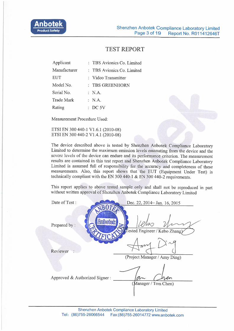
R&TTE (Radio) TEST REPORT for
TBS Avionics Co. Limited
Video Transmitter Model No.: TBS GREENHORN
Report Number : R011412646T Date of Test : Dec. 22, 2014~ Jan. 16, 2015 Date of Report : Jan. 20, 2015
Prepared for : TBS Avionics Co. Limited Address : Room G, 4/F, Winner Factory Building, No.55 Hung To Road,
Kwun Tong, Kln, HK
Prepared By : Shenzhen Anbotek Compliance Laboratory Limited Address : 1/F., Building 1, SEC Industrial Park, No.0409 Qianhai Road,
Nanshan District, Shenzhen, Guangdong, China Tel: (86) 755-26066544 Fax: (86) 755-26014772

Shenzhen Anbotek Compliance Laboratory Limited Page 2 of 19 Report No. R011412646T
Shenzhen Anbotek Compliance Laboratory Limited
Tel:(86)755-26066544 Fax:(86)755-26014772 www.anbotek.com
TABLE OF CONTENT
Description
Page Test Report 1. GENERAL INFORMATION ......................................................................................................... 4
1.1. Description of Device (EUT) ..................................................................................................... 4 1.2. Description of Test Facility ........................................................................................................ 5 1.3. Measurement Uncertainty .......................................................................................................... 5 1.4. Test Standards ............................................................................................................................. 6 1.5. Auxiliary Equipment Used during Test ...................................................................................... 6
2. MEASURING DEVICE AND TEST EQUIPMENT .................................................................... 7
3. TECHNICAL TEST ........................................................................................................................ 8 3.1. Summary of Test Results ............................................................................................................ 8 3.2. Test Report ................................................................................................................................. 8 3.3. Description of Test Modes ......................................................................................................... 8
3.4. TECHNICAL REQUIREMENTS ............................................................................................... 9
3.4.1. EQUIVALENT ISOTROPICALLY RADIATED POWER ................................................... 9 3.4.1.1. Standard Applicable ............................................................................................................. 9 3.4.1.2.Test Procedure ....................................................................................................................... 9 3.4.1.3. Test Result .......................................................................................................................... 10
3.4.2. PERMITTED RANGE OF OPERATING FREQUENCIES ............................................... 11 3.4.2.1. Standard Application .......................................................................................................... 11 3.4.2.2. Test Procedure .................................................................................................................... 11 3.4.2.3. Test Result .......................................................................................................................... 12
3.4.3. UNWANTED EMISSIONS IN THE SPURIOUS DOMAIN ............................................... 13 3.4.3.1. Standard Application .......................................................................................................... 13 3.4.3.2. Measurement Uncertainty .................................................................................................. 13 3.4.3.3. Test Procedure .................................................................................................................... 14 3.4.3.4. Test Result .......................................................................................................................... 16
3.4.4. RECEIVER REQUIREMENTS-SPURIOUS RADIATIONS ............................................. 17 3.4.4.1. Measurement Uncertainty .................................................................................................. 17 3.4.4.2. Limit of Spurious Emissions .............................................................................................. 17 3.4.4.3. Test Procedure .................................................................................................................... 17 3.4.4.4. Corrected Amplitude & Margin Calculation ...................................................................... 17 3.4.4.5. Measurement Result ........................................................................................................... 18
APPENDIX I (TEST PHOTOGRAPHS) ........................................................................................ 19 1. Photo of Emission Test ................................................................................................................ 19

Shenzhen Anbotek Compliance Laboratory Limited Page 4 of 19 Report No. R011412646T
Shenzhen Anbotek Compliance Laboratory Limited
Tel:(86)755-26066544 Fax:(86)755-26014772 www.anbotek.com
1. GENERAL INFORMATION
1.1. Description of Device (EUT)
EUT : Video Transmitter
Model Number : TBS GREENHORN Test Voltage : DC 3V Via Battery
Frequency : 5733~5866MHz
Channel : 24 Channels Antenna Gain : 0dBi
(The device uses an integral PCB antenna which is not intended and easy to modify.)
Applicant : TBS Avionics Co. Limited Address : Room G, 4/F, Winner Factory Building, No.55 Hung To Road,
Kwun Tong, Kln, HK
Manufacturer : TBS Avionics Co. Limited Address : Room G, 4/F, Winner Factory Building, No.55 Hung To Road,
Kwun Tong, Kln, HK Factory : TBS Avionics Co. Limited Address : Room G, 4/F, Winner Factory Building, No.55 Hung To Road,
Kwun Tong, Kln, HK Date of receipt : Dec. 22, 2014
Date of Test : Dec. 22, 2014~ Jan. 16, 2015

Shenzhen Anbotek Compliance Laboratory Limited Page 5 of 19 Report No. R011412646T
Shenzhen Anbotek Compliance Laboratory Limited
Tel:(86)755-26066544 Fax:(86)755-26014772 www.anbotek.com
1.2. Description of Test Facility
The test facility is recognized, certified, or accredited by the following organizations: CNAS - LAB Code: L3503 Shenzhen Anbotek Compliance Laboratory Limited., Laboratory has been assessed and in compliance with CNAS/CL01: 2006 accreditation criteria for testing laboratories (identical to ISO/IEC 17025:2005 General Requirements) for the Competence of Testing Laboratories. FCC-Registration No.: 752021 Shenzhen Anbotek Compliance Laboratory Limited, EMC Laboratory has been registed and fully described in a report filed with the (FCC) Federal Communications Commission. The acceptance letter from the FCC is maintained in our files. Registration 752021, July 10, 2013. IC-Registration No.: 8058A-1 Shenzhen Anbotek Compliance Laboratory Limited., EMC Laboratory has been registered and fully described in a report filed with the (IC) Industry Canada. The acceptance letter from the IC is maintained in our files. Registration 8058A-1, February 22, 2013. Test Location All Emissions tests were performed at Shenzhen Anbotek Compliance Laboratory Limited. at 1/F., Building 1, SEC Industrial Park, No.0409 Qianhai Road, Nanshan District, Shenzhen, Guangdong, China
1.3. Measurement Uncertainty
Radiation Uncertainty : Ur = 4.3dB
Conduction Uncertainty : Uc = 3.4dB

Shenzhen Anbotek Compliance Laboratory Limited Page 6 of 19 Report No. R011412646T
Shenzhen Anbotek Compliance Laboratory Limited
Tel:(86)755-26066544 Fax:(86)755-26014772 www.anbotek.com
1.4. Test Standards
ETSI EN 300 440-1 V1.6.1 (2010-08) Electromagnetic compatibility and Radio spectrum Matters (ERM);
Short range devices; Radio equipment to be used
in the 1 GHz to 40 GHz frequency range; Part 1: Technical characteristics and test methods
ETSI EN 300 440-2 V1.4.1 (2010-08)
Electromagnetic compatibility and Radio spectrum Matters (ERM); Short range devices;
Radio equipment to be used in the 1 GHz to 40 GHz frequency range;
Part 2: Harmonized EN covering the essential requirements of article 3.2 of the R&TTE Directive
Note: All radiated measurements were made in all three orthogonal. The values reported are the maximum values.
1.5. Auxiliary Equipment Used during Test
N/A

Shenzhen Anbotek Compliance Laboratory Limited Page 7 of 19 Report No. R011412646T
Shenzhen Anbotek Compliance Laboratory Limited
Tel:(86)755-26066544 Fax:(86)755-26014772 www.anbotek.com
2. MEASURING DEVICE AND TEST EQUIPMENT Equipment Manufacturer Model # Serial # Date of Cal. Cal. IntervalSpectrum Analyzer
Agilent E4407B US39390
582 Aug. 08, 2014 1 Year
Test Receiver Rohde & Schwarz
ESPI 101604 Apr. 22, 2014 1 Year
Test Receiver Rohde & Schwarz
ESCI 100627 Apr. 22, 2014 1 Year
Bilog Broadband Antenna
Schwarzbeck VULB916
3 VULB
9163-289Apr. 24, 2014 1 Year
Double Ridged Horn Antenna
Instruments corporation
GTH-0118 351600 Apr. 04, 2014 1 Year
Preamplifier Instruments corporation
EMC011830
980100 Aug. 08, 2014 1 Year
Pre-amplifier SONOMA 310N 186860 Aug. 08, 2014 1 Year AC Power
Source Sepcial power
system YF650 N/A N/A N/A
Pulse Limiter Rohde & Schwarz
ESH3-Z2 N/A N/A N/A
EMI Test Software EZ-EMC
SHURPLE EZ-EMC N/A N/A N/A
Coaxial Cable N/A N/A N/A N/A N/A Coaxial Cable N/A N/A N/A N/A N/A Coaxial Cable N/A N/A N/A N/A N/A
3m Semi-Anechoic
Chamber
Zhong Yu Electronic
N/A N/A N/A N/A

Shenzhen Anbotek Compliance Laboratory Limited Page 8 of 19 Report No. R011412646T
Shenzhen Anbotek Compliance Laboratory Limited
Tel:(86)755-26066544 Fax:(86)755-26014772 www.anbotek.com
3. Technical Test
3.1. Summary of Test Results
No Deviations from the technical specification(s) were ascertained in the course of the tests Performed
Final Verdict: (only “Passed” if all single measurements are “Passed”)
Passed
3.2. Test Report
Test Report Reference
ETSI EN 300 440-2 V1.6.1 (2010-08) Description of Test Rule Result
Transmitter requirements Section 4.2.1 Equivalent isotropically radiated power Section 4.2.1.1 Complies
Permitted range of operating frequencies Section 4.2.1.2 Complies Unwanted emissions in the spurious domain Section 4.2.1.3 Complies
Duty cycle Section 4.2.1.4 N/Anote(1) Receiver requirements Section 4.2.2
Adjacent channel selectivity Section 4.2.2.1 N/Anote(2) Blocking or desensitization Section 4.2.2.2 N/Anote(3)
Spurious radiations Section 4.2.2.3 Complies Note (1): Not applicable , This requirement applies to RFID transmitters operating in 2 446 MHz to 2 454 MHz only. Note (2): Not applicable, since the test applies to class 1 receivers only Note (3): Not applicable, since the test applies to class 1 and class 2 receivers only
3.3. Description of Test Modes
The EUT has been tested under operating condition. Manual control the EUT for staying in continuous transmitting mode. Channel Low(5733MHz), Channel Mid(5800MHz) and Channel High(5866MHz) are chosen for the final testing.

Shenzhen Anbotek Compliance Laboratory Limited Page 9 of 19 Report No. R011412646T
Shenzhen Anbotek Compliance Laboratory Limited
Tel:(86)755-26066544 Fax:(86)755-26014772 www.anbotek.com
3.4. Technical Requirements
3.4.1. Equivalent isotropically radiated power
3.4.1.1. Standard Applicable
According to ETSI EN 300 440-2 V1.4.1, The equivalent isotropically radiated power, as defined in EN 300 440-1 [1], clause 7.1.1, shall not exceed the limits in EN 300 440-1 [1], clause 7.1.3, table 4. This requirement applies to transmitters with an integral or dedicated antenna.
3.4.1.2.Test Procedure
The measurement arrangement see following figure:

Shenzhen Anbotek Compliance Laboratory Limited Page 10 of 19 Report No. R011412646T
Shenzhen Anbotek Compliance Laboratory Limited
Tel:(86)755-26066544 Fax:(86)755-26014772 www.anbotek.com
1. The transmitter output was connected to the spectrum analyzer through an attenuator. 2. The transmitter output was connected to the spectrum analyzer via a cable and cable loss is used
as the offset of the spectrum analyzer. 3. Set both RBW and VBW of spectrum analyzer to 100KHz with convenient frequency span
including 100MHz bandwidth from lower band edge. Then detector set to peak and max hold this trace.
4. For peak power measurements, a spectrum analyser or frequency-selective voltmeter shall be used
and tuned to the transmitter carrier at which the highest level is detected. 5. The equivalent isotropically radiated power is then calculated from the measured value, the known
antenna gain, relative to an isotropic antenna. 6. The transmitter shall be tested under normal and extreme test conditions
3.4.1.3. Test Result
Temperature ( ℃ ) 22~23Humidity ( %RH ) 40~42
Barometric Pressure ( mbar ) 950~1000
Operating Mode Continuous Transmitting
TEST CONDITIO
N:
Frequency
(MHz)
Power
(dBm)
Factor
(dB)
Corrected Power
(dBm)
Limit
(dBm)
Margin
(dBm)
Result
Normal 5733 11.22 1.5 12.72 13.97 -1.25 PASS
5800 10.98 1.5 12.48 13.97 -1.49 PASS
5866 10.89 1.5 12.39 13.97 -1.58 PASS
Extreme 5733 11.13 1.5 12.63 13.97 -1.34 PASS
5800 11.09 1.5 12.59 13.97 -1.38 PASS
5866 10.94 1.5 12.44 13.97 -1.53 PASS

Shenzhen Anbotek Compliance Laboratory Limited Page 11 of 19 Report No. R011412646T
Shenzhen Anbotek Compliance Laboratory Limited
Tel:(86)755-26066544 Fax:(86)755-26014772 www.anbotek.com
3.4.2. Permitted range of operating frequencies
3.4.2.1. Standard Application
The permitted range of operating frequencies includes all frequencies on which the equipment may operate within an assigned frequency band. The operating frequency range shall be declared by the manufacturer.
The frequency range of the equipment is determined by the lowest and highest frequencies occupied by the power envelope. FH is the highest frequency of the power envelope, it is the frequency furthest above the frequency of maximum power where the output power drops below the level of –80dBm/Hz spectral power density (-30dBm if measured in a 100kHz bandwidth) eirp.
FL is the lowest frequency of the power envelope; it is the frequency furthest below the frequency of maximum power where the output power drops below the level of –80dBm/Hz spectral lower density (-30dBm if measured in a 100kHz bandwidth) eirp.
3.4.2.2. Test Procedure
Put the spectrum analyzer in video averaging mode with a minimum of 50 sweeps selected; Select the lowest operating frequency of the equipment under test and activate the transmitter with modulation applied. The RF emission of the equipment shall be displayed on the spectrum analyzer. Using the marker of the spectrum analyzer, find lowest frequency below the operating frequency at which spectral power density drops below the required value. Select the highest operating frequency of the equipment under test and find the highest frequency at which the spectral power density drop below the required value. The difference between the frequencies measured in step 3 and step 4 is the operating frequency range.

Shenzhen Anbotek Compliance Laboratory Limited Page 12 of 19 Report No. R011412646T
Shenzhen Anbotek Compliance Laboratory Limited
Tel:(86)755-26066544 Fax:(86)755-26014772 www.anbotek.com
3.4.2.3. Test Result
Temperature ( ℃ ) 22~23Humidity ( %RH ) 40~42
Barometric Pressure ( mbar ) 950~1000
Operating Mode Continuous Transmitting
Test Condition Test Result
Voltage (V) Temperature
(℃) FL(MHz) FH(MHz)
Normal Condition
DC 5V 24 5729.59 5869.97
Extreme Condition
DC 5.5V -10 5730.13 5869.13
+55 5729.76 5869.49
DC 4.5V -10 5729.68 5869.85
+55 5730.12 5869.66
Limit FL﹥5725MHz FH<5875MHz
Conclusion PASS PASS

Shenzhen Anbotek Compliance Laboratory Limited Page 13 of 19 Report No. R011412646T
Shenzhen Anbotek Compliance Laboratory Limited
Tel:(86)755-26066544 Fax:(86)755-26014772 www.anbotek.com
3.4.3. Unwanted emissions in the spurious domain
3.4.3.1. Standard Application
According to ETSI EN 300 440-2 V1.4.1, Unwanted emissions in the spurious domain (spurious emissions) are those at frequencies beyond the limit of 250 % of the necessary bandwidth above and below the centre frequency of the emission. The level of spurious emissions shall be measured as either: a) i) their power level in a specified load (conducted emission); and ii) their effective radiated power when radiated by the cabinet and structure of the equipment (cabinet radiation); or b) their effective radiated power when radiated by the cabinet and the integral or dedicated antenna, in the case of equipment fitted with such an antenna and no permanent RF connector. For measurements above 1 000 MHz the peak value shall be measured using a spectrum analyser. The "max hold" function of a spectrum analyser shall be used. For measurements up to 1 000 MHz the quasi-peak detector set in accordance with the specification of CISPR 16 [1] shall be used. The power of any spurious emission shall not exceed the following values given in table 5.
Frequency ranges 47MHz to 74MHz
87.5MHz to 108MHz 174MHz to 230MHz 470MHz to 862MHz
Other frequencies≦1000MHz
Frequencies >1000MHz State
Operating 41.25 dBuV/m 59.20 dBuV/m 65.23 dBuV/m Standby 38.22 dBuV/m 38.22 dBuV/m 48.24 dBuV/m
3.4.3.2. Measurement Uncertainty
All measurements involve certain levels of uncertainties, especially in field of EMC. The factors contributing to uncertainties are spectrum analyzer, cable loss, antenna factor calibration, antenna directivity, antenna factor variation with height, antenna phase center variation, antenna factor frequency interpolation, measurement distance variation, site imperfections, mismatch (average), and system repeatability. Based on NIS 81, The Treatment of Uncertainty in EMC Measurements, the best estimate of the uncertainty of a radiation emissions measurement is +4.0 dB.

Shenzhen Anbotek Compliance Laboratory Limited Page 14 of 19 Report No. R011412646T
Shenzhen Anbotek Compliance Laboratory Limited
Tel:(86)755-26066544 Fax:(86)755-26014772 www.anbotek.com
3.4.3.3. Test Procedure
Radiated measurements were performed with the aid of a test antenna and measurement instruments. The test antenna and measurement instrument shall be calibrated according to the procedure defined in this annex. The equipment to be measured and the test antenna shall be oriented to obtain the maximum emitted power level. This position was recorded in the measurement report. The frequency range was measured in this position. Preferably, radiated measurements were performed in an anechoic chamber. For other test sites corrections may be needed. The following test procedure applies: a) a test site which fulfils the requirements of the specified frequency range of this measurement shall be used. The test antenna were oriented initially for vertical polarization unless otherwise stated and the transmitter under test shall be placed on the support in its standard position and switched on; b) for average power measurements a non-selective voltmeter or wide band spectrum analyzer were used. For other measurements a spectrum analyzer or selective voltmeter shall be used and tuned to the measurement frequency. In either case a) or b), the test antenna shall be raised or lowered, if necessary, through the specified height range until the maximum signal level is detected on the spectrum analyzer or selective voltmeter.
c) the transmitter shall be rotated through 360o about a vertical axis until a higher maximum signal is received;
d) the test antenna shall be raised or lowered again, if necessary, through the specified height range until a maximum is obtained. This level shall be recorded.
NOTE: This maximum may be a lower value than the value obtainable at heights outside the specified limits.

Shenzhen Anbotek Compliance Laboratory Limited Page 15 of 19 Report No. R011412646T
Shenzhen Anbotek Compliance Laboratory Limited
Tel:(86)755-26066544 Fax:(86)755-26014772 www.anbotek.com
The test antenna need not be raised or lowered if the measurement is carried out on a test site according to clause b.1.2. This measurement shall be repeated for horizontal polarization. The actual signal generated by the measured equipment may be determined by means of a substitution measurement in which a known signal source replaces the device to be measured, see figure C.2. Preferably, this method of measurement shall be used in an anechoic chamber. For other test sites corrections may be needed.
a) using measurement arrangement NO.2, the substitution antenna shall replace the transmitter antenna in the same position and in vertical polarization. The frequency of the signal generator shall be adjusted to the measurement frequency. The test antenna shall be raised or lowered, if necessary, to ensure that the maximum signal is still received. The input signal to the substitution antenna shall be adjusted in level until an equal or a known related level to that detected from the transmitter is obtained in the transmitter is obtained in the test receiver; - the radiated power is equal to the power supplied by the signal generator, increased by the known relationship if necessary and after corrections due to the gain of the substitution antenna and the cable loss between the signal generator and the substitution antenna; b) this measurement shall be repeated with horizontal and vertical polarization.

Shenzhen Anbotek Compliance Laboratory Limited Page 16 of 19 Report No. R011412646T
Shenzhen Anbotek Compliance Laboratory Limited
Tel:(86)755-26066544 Fax:(86)755-26014772 www.anbotek.com
3.4.3.4. Test Result
Temperature ( ℃ ) 22~23Humidity ( %RH ) 40~42
Barometric Pressure ( mbar ) 950~1000
Operating Mode Continuous Transmitting (CH Low) Tx mode
Frequency MHz
Antenna Polar (H/V)
Read Level(dBuV)
Correct Factor(dB)
Measurement(dBuV/m)
Limit (dBuV/m)
Margin (dB)
11467.15 H 45.17 -8.73 36.44 65.23 -28.79
17199.83 H 46.94 -8.16 38.78 65.23 -26.45
22933.05 H 45.97 -7.42 38.55 65.23 -26.68
--- --- --- --- --- --- ---
--- --- --- --- --- --- ---
--- --- --- --- --- --- ---
11467.15 V 46.84 -11.76 35.08 65.23 -30.15
17199.83 V 49.36 -8.66 40.70 65.23 -24.53
22933.05 V 49.12 -7.53 41.59 65.23 -23.64
--- --- --- --- --- --- ---
--- --- --- --- --- --- ---
--- --- --- --- --- --- ---
Standby mode
Frequency MHz
Antenna Polar (H/V)
Read Level(dBm)
Correct Factor(dB)
Measurement(dBuV/m)
Limit (dBuV/m)
Margin (dB)
315.29 V 6.15 13.24 19.39 38.22 -18.83
379.46 V 5.77 16.85 22.62 38.22 -15.60
492.58 V 5.09 18.41 23.50 38.22 -14.72
644.79 V 4.36 20.25 24.61 38.22 -13.61
876.54 V 4.94 23.66 28.60 38.22 -9.62
205.71 H 6.75 9.10 15.85 38.22 -22.37
429.91 H 8.29 16.85 25.14 38.22 -13.08
681.02 H 3.61 18.20 21.81 38.22 -16.41

Shenzhen Anbotek Compliance Laboratory Limited Page 17 of 19 Report No. R011412646T
Shenzhen Anbotek Compliance Laboratory Limited
Tel:(86)755-26066544 Fax:(86)755-26014772 www.anbotek.com
3.4.4. Receiver requirements-Spurious radiations
3.4.4.1. Measurement Uncertainty
All measurements involve certain levels of uncertainties, especially in field of EMC. The factors contributing to uncertainties are spectrum analyzer, cable loss, antenna factor calibration, antenna directivity, antenna factor variation with height, antenna phase center variation, antenna factor frequency interpolation, measurement distance variation, site imperfections, mismatch (average), and system repeatability. The Treatment of Uncertainty in EMC Measurements, the best estimate of the uncertainty of a radiation emissions measurement is +4.0 dB.
3.4.4.2. Limit of Spurious Emissions
Frequency Range 1000MHz > 1000MHz
Power Limit 2nW(38.22 dBuV/m) 20nW(48.24 dBuV/m)
3.4.4.3. Test Procedure
Rx was placed on a nonmetal table which is 1.5 meter above the grounded reference plane and set to work in normal operation mode. Details refer to ETSI EN 300 220-1 V1.3.1 subclause 9.4.3. All data was recorded in the peak detection mode. Quasi-peak readings performed only when an emission was found to be marginal (within -4 dBV of specification limitation), and are distinguished with a "QP" in the data table. The EUT was operating at normal to represent worst case during final qualification test.
3.4.4.4. Corrected Amplitude & Margin Calculation
The Corrected Amplitude is calculated by adding the Antenna Factor and Cable Factor, and subtracting the Amplifier Gain from the Amplitude reading. The basic equation is as follows:
Corr. Ampl. = Indicated Reading + Antenna Factor + Cable Factor - Amplifier Gain
The “Margin” column of the following data tables indicates the degree of compliance with the applicable limit. For example, a margin of -7dBV means the emission is 7dBV below the maximum limit for Class B. The equation for margin calculation is as follows:
Margin = Corr. Ampl. –Limit

Shenzhen Anbotek Compliance Laboratory Limited Page 18 of 19 Report No. R011412646T
Shenzhen Anbotek Compliance Laboratory Limited
Tel:(86)755-26066544 Fax:(86)755-26014772 www.anbotek.com
3.4.4.5. Measurement Result
Temperature ( ℃ ) 22~23Humidity ( %RH ) 40~42
Barometric Pressure ( mbar ) 950~1000
Operating Mode Continuous Transmitting
Frequency MHz
Antenna Polar (H/V)
Read Level(dBuV)
Correct Factor(dB)
Measurement(dBuV/m)
Limit (dBuV/m)
Margin (dB)
1456.39 H 42.97 -7.6 35.37 48.24 -12.87
1577.43 H 41.03 -8.4 32.63 48.24 -15.61
1905.67 H 36.54 -7.3 29.24 48.24 -19.00
2446.39 H 34.79 -7.2 27.59 48.24 -20.65
2793.82 H 39.58 -7.6 31.98 48.24 -16.26
3305.47 H 38.76 -7.6 31.16 48.24 -17.08
1116.25 V 34.99 -7.1 27.89 48.24 -20.35
1497.08 V 42.56 -7.3 35.26 48.24 -12.98
1966.34 V 45.25 -8.0 37.25 48.24 -10.99
2287.03 V 45.03 -7.1 37.93 48.24 -10.31
2708.93 V 43.14 -7.2 35.94 48.24 -12.30
3145.62 V 39.88 -7.6 32.28 48.24 -15.96

Shenzhen Anbotek Compliance Laboratory Limited Page 19 of 19 Report No. R011412646T
Shenzhen Anbotek Compliance Laboratory Limited
Tel:(86)755-26066544 Fax:(86)755-26014772 www.anbotek.com
APPENDIX I (TEST PHOTOGRAPHS)
1. Photo of Emission Test