r1_100pn... · web view2.4 - set-point configuration14 2.5 - pid control configuration15 2.6 -...
TRANSCRIPT
R1-100P-N MANUAL
1 - Installation..........................................................................................................................11.1 - Packaging check....................................................................................................................1
1.2 - Dimensions...........................................................................................................................2
1.3 - Fixing method.......................................................................................................................2
1.4 - Electric wiring.......................................................................................................................41.4.1 - Supply and absorption............................................................................................51.4.2 - Control inputs.........................................................................................................51.4.3 - Command inputs....................................................................................................61.4.4 - Control outputs.......................................................................................................71.4.5 - Serial link...............................................................................................................81.4.6 - Earth wiring and shielding...................................................................................101.4.7 - Communication protocol.....................................................................................111.4.8 - Device identification............................................................................................11
2 - Operation..........................................................................................................................122.1 - Introduction.........................................................................................................................12
2.2 - Input configuration..............................................................................................................12
2.3 - Control output configuration...............................................................................................13
2.4 - Set-point configuration.......................................................................................................14
2.5 - PID control configuration...................................................................................................15
2.6 - Alarm configuration............................................................................................................16
2.7 - Start up sequence programming..........................................................................................17
2.8 - Supervision.........................................................................................................................18
2.9 - Self-test led.........................................................................................................................18
3.3 - Personal computer supervision...........................................................................................27
A – Gates list.........................................................................................................................28A.1 – Numeric gates list (holding registers)...............................................................................28
A.2 – Digital gates list (coils)......................................................................................................32

R1-100P-N MANUAL
1 - Installation
0.1 - Packaging check
Before starting installation, it is necessary to check that the packaging content is in compliance with your order. In the packaging there must be:
#1 R1-100P series controller#1 instruction manual
Check that the model controller code is in compliance with the ordered code. If it is not correct, please contact Sielco.The R1-100P has the following features:
- 24 Vdc power supply- 14 PT100/RTD sensor analog inputs with the following features:
- temperature range: - 199.9 °C + 500.0 °C- resolution: 12 bit- precision: ±0,05 % full scale
- 3 digital inputs with the following features:- optoisolated with common ground- state 1: 0 2 Vdc- state 0: 3 32 Vdc
Verify that the manual edition correspond to the purchase year.R1-100P series controllers are covered by 1 year of warranty except for damages caused by tampering or wrong wiring.The label on the controller backside certificates the purchase date.
0.2 - Dimensions
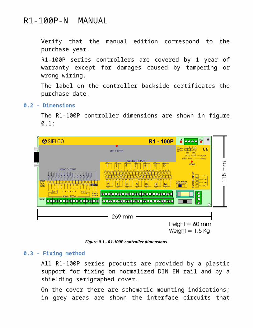
The R1-100P controller dimensions are shown in figure 0.1:
R1-100P-N MANUAL
Figure 0.1 - R1-100P controller dimensions.
0.3 - Fixing method
All R1-100P series products are provided by a plastic support for fixing on normalized DIN EN rail and by a shielding serigraphed cover.On the cover there are schematic mounting indications; in grey areas are shown the interface circuits that are inside the module, in yellow areas are shown common use sensors and actuators to be connected externally.The cover serigraph provides, obviously, only a general wiring diagram and cannot show every possible connection cases; for this reason it is necessary, before starting R1-100P installation, to read carefully this manual.Do not use excessive pressure on the cover, mounting or dismounting the module on the rail.Remember to mount or dismount module with supply voltage switched off or not connected (see paragraph 0.4.1).

R1-100P-N MANUAL
0.4 - Electric wiring

R1-100P-N MANUAL
Figure 0.2 - R1-100P scheme.
M1 Pt100 input screws (see par. 0.4.2)M2 Supply screws 24Vcc (see par. 0.4.1)M3 NPN digital outputs screws (see par. 0.4.4)C1 Communication serial channel connector (see par. 0.4.8)C2 Command digital inputs connector (see par. 0.4.3)C3 F1-10 programming console connectorD1 Address and communication protocol selection dipswitchS1 Write protect Flash-memory switch J1 RS422/RS485 jumper J2 Output pull up selection jumper (15V/24V)Com Communication ledLed TX Transmitted data ledLed RX Received data ledSelf-test Self – test led
0.1.1 - Supply and absorption
The controller needs a 24 Vdc (18V < Vdc < 36 V) supply (M2 screws) and absorbs a 250 mA maximum current.
0.1.2 - Control inputs
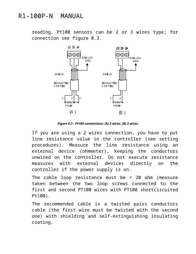
R1-100P controllers have 14 Pt100 control inputs (M1 screws). Be sure that the sensors used are in compliance with IEC 751 standard. Choosing the sensor, be sure that the wires (2 or 3) connected to the sensor are electrically isolated from its metallic case. Dispersion currents towards the sensor metallic case can be detrimental to the precision of the reading. Pt100 sensors can be 2 or 3 wires type; for connection see figure 0.3.

R1-100P-N MANUAL
Figure 0.3 - Pt100 connections: (A) 3 wires; (B) 2 wires.
If you are using a 2 wires connection, you have to put line resistance value in the controller (see setting procedures). Measure the line resistance using an external device (ohmmeter), keeping the conductors unwired on the controller. Do not execute resistance measures with external devices directly on the controller if the power supply is on.The cable loop resistance must be < 20 ohm (measure taken between the two loop screws connected to the first and second PT100 wires with PT100 shortcircuited Pt100).The recommended cable is a twisted pairs conductors cable (the first wire must be twisted with the second one) with shielding and self-extinguishing insulating coating.Do not connect Pt100 using single wires not belonging to the same cable: the outward wire resistance (first wire connected at the first screw of each set of three) must be the same of the inward wire one (second wire connected at the second screw of each set of three).
0.1.3 - Command inputs
R1-100P controllers are equipped with 3 digital inputs with common ground (C2 connector). Input state is OFF for voltage between 3 and 32Vcc, ON for voltage between 0 and 2Vcc. On C2 connector, with 3 digital inputs, is provided the device ground by which activate the inputs (simple contact as relay or mechanical switch).
R1-100P-N MANUAL
0.1.4 - Control outputs
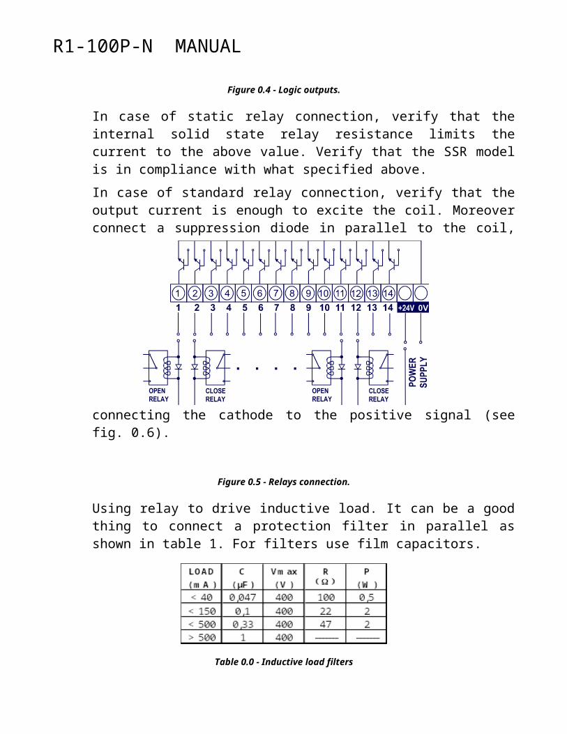
R1-100 controller has 14 transistor outputs. Logic outputs are NPN transistor with selectable pull up, by J2 jumper, between 15Vcc and 24Vcc and with 30 mA of output channel Imax. These outputs can be used to command standard or solid state relays (SSR) see figure 0.5.
Figure 0.4 - Logic outputs.
In case of static relay connection, verify that the internal solid state relay resistance limits the current to the above value. Verify that the SSR model is in compliance with what specified above.In case of standard relay connection, verify that the output current is enough to excite the coil. Moreover connect a suppression diode in parallel to the coil, connecting the cathode to the positive signal (see fig. 0.6).

R1-100P-N MANUAL
Figure 0.5 - Relays connection.
Using relay to drive inductive load. It can be a good thing to connect a protection filter in parallel as shown in table 1. For filters use film capacitors.
Table 0.0 - Inductive load filters
It is better to supply SSR and relays with the same power supply used for the controllers.
0.1.5 - Serial link
R1-100P controller can be connected to:to a remote PC or to a master unit for supervision and configuration using RS422 or RS485 (J1 jumper) serial link (C1 connector)to programming and supervision console F-10 (C3 connector)
Supervisor connection
To connect to R1-100P controllers, it is necessary to use a RS422/485 serial interface that usually are not standard equipment in personal computers. Sielco produce C1-25 model , a RS232-422/485 serial interface converter with triple optical isolation; see table 0.2.
Table 0.1 - C1-25 converter input/output signals.
R1-100P-N MANUAL
This converter can be connected to PC serial port (COM) and to R1-100P C1 connector as shown in table 0.3.
Table 0.2 - C1-25 - R1-100P (RS 422/485) wiring.
In case of alternative products choice, it is better to choose optically isolated products with galvanically isolated grounds.
F1-10 programming and supervision panel
It is possible to connect R1-100P controller to the local operator panel F1-10 to provide a synthetic programming and supervision.
Figure 0.6 - F1-10 operator panel.

R1-100P-N MANUAL
0.1.6 - Earth wiring and shielding
Earth wiring
It is suggested to make the following earth:- leave serial channel ground unwired- device ground (pin #4 connector C2) must be connected to earth- the power supply negative signal must be connected to a local earth
It is a good thing to avoid to share the same wire path with power devices as inverter, drives etc.
Inputs shielding
Temperature reading is based on low intensity signal detection (Pt100 and potentiometer).To improve the sensors reading particularly in environment noise affected by power devices (motor driver , power contact etc.), follow these shielding rules:
- Use shielded and twisted cables for sensors connection.- Keep connection cables as short as possible.- It is a good thing to avoid to share the same wire path with power
devices as inverter, drives etc..- Connect all sensor cable metal shields to the controller negative screw,
leaving them not connected by the sensor side (parasite currents on the shields can induce disturbances that can affect sensor reading).
- Connect all sensor cable metal shields to the pin n°4 of C2 connector.
Serial communication wire cable
Use shielded and twisted cable in compliance with EIA RS422 or EIA RS485.Recommended cable: Belden 9841 (RS485) 9842 (RS422).Maximum signal loss: 6 dB.Maximum line capacitance: 100 nf.Maximum line length: 1200 m.
0.1.7 - Communication protocol
Software communication protocol is realised according to ModBus ASCII or RTU standard: protocol selection is made by #7 selector of dipswitch (ON=RTU, OFF=ASCII)ASCII protocol features

R1-100P-N MANUAL
Baud rate 9600 / 19200Data bits 7Parity bit evenStop bit 1
RTU protocol featuresBaud rate 9600 / 19200Data bits 8Parity bit noneStop bit 1
The baudrate selection is made by #8 selector of dipswitch (ON=19200, OFF=9600).
0.1.8 - Device identification
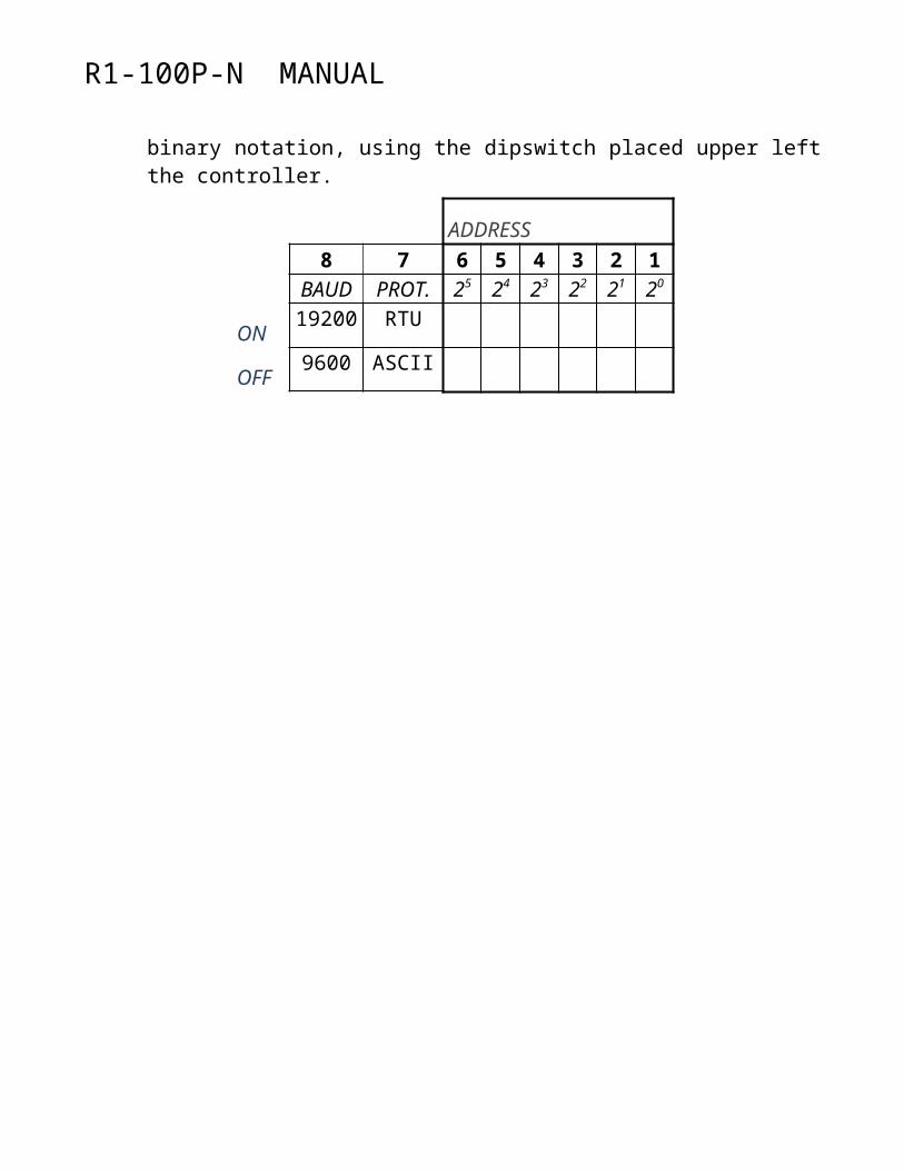
Up to 63 R1-100P controllers can be connected to same master unit. Modules identification is made through binary notation, using the dipswitch placed upper left the controller.
ADDRESS8 7 6 5 4 3 2 1
BAUD PROT. 25 24 23 22 21 20
ON19200 RTU
OFF9600 ASCII
R1-100P-N MANUAL
2 - Operation
0.1 - IntroductionThe R1-100P-N multiloop temperature controller can handle up to 14 independent PID control loops; it provides 14 analog input channels to read temperature through Pt100/RTD sensor (2 or 3 wires).The controller also provides 3 digital inputs, which can be used as follow:
- input 1 on disables all control loops and resets start-up procedure;- input 2 on puts all loops in manual operation mode;- input 3 on selects second set-point for all control loops.
0.2 - Input configurationInput configuration allows independent setting for each loop of options and parameters for reading temperature:
- Sensor presence (Pt100 not connected)- Line resistance value (xxx.xx ohm)- Read options
- bit 0: filter on temperature reading- bit 1: rounding- bit 2: automatic compensation of line resistance

R1-100P-N MANUAL
In case of Pt100 sensor not connected, the 0.0 °C temperature value is forced and all alarms are disabled.Filters on reading are necessary only in case of disturbance; the instantaneous reading value is substituted by a dynamic mean calculated on a period of 8 seconds.The rounding option has no effect on control; it allows filtering of small changes (< 1 °C) of temperature values available for supervision (Tr).The compensation value of the line resistance of Pt100 sensors can be manually set by the operator or automatically calculated by the controller; to do this it is enough to set the automatic compensation option; when the procedure ends, the compensation option resets and the compensation value is automatically updated.
0.3 - Control output configuration Output configuration allows independent setting, for each of the 14 available output channels, of the following parameters:
- Control type- 0 = none- 1 = On/Off primary control- 2 = time proportioning (SSR) primary control- 3 = analog primary control- 4 = On/Off secondary control - 5 = time proportioning (SSR) secondary control- 6 = analog secondary control
- Reference loop (0, 1 ... 14)- Duty cycle (xx sec)- Low value (xxx.x %)- High value (xxx.x %)- Ramp value (xxx.x %/sec)
If output is configured, it is necessary to specify the reference loop. In case of On/Off control, the control output goes on or off when the 100% or 0% values are reached; in case of time proportioning control, the duty cycle parameter must be specified; in case of analog control, the output channel must be connected to the pwm to analog converter C1-10.
R1-100P-N MANUAL
High and low values limit the range of the control output; the ramp value allows setting of the maximum variation per second of the control output.
0.4 - Set-point configurationSet point configuration allows independent setting for each loop of options and parameters which control the set point value and the up/down slope in case of set-point variation:
- Set-point type- 0 = programmed value- 1 = channel 1 temperature.........................................- 14 = channel 14 temperature
- Set-point 1 (xxx.x °C)- Set-point 2 (xxx.x °C)
- Set-point increment step (xxx.x °C)- Set point increment time (xxx sec)- Set-point decrement step (xxx.x °C)- Set point decrement time (xxx sec)
- Set-point options- bit 0: "soft start"- bit 1: "holdback"
The set-point type parameter allows using as control set-point the programmed temperature set-point value (type=0) or the temperature value read by one of the input channels (type=1..14).The selection between set-point 1 and 2 is controlled via the third logic input (off = SP1).In case of set-point update, the current set point points towards the final set-point with a ramp which depends on parameters set-point step and set-point time; for example, if the increment is 0.1 °C each 5 seconds, that means that the total ramp time for a set-point variation of 10.0 °C will be 500 seconds.With the "soft-start" option enabled, after power fail or a manual operation the current set-point is forced equal to the current temperature value.

R1-100P-N MANUAL
With the "holdback" option enabled, the set-point ramp is suspended in case of an out of temperature alarm.
0.5 - PID control configuration PID control parameters can be set independently for each loop; these are:
- Control type (0=none, 1=heat, 2=cool, 3=heat/cool)- PID control cycle time (xxx sec)- Proportional Band (xxx.x °C)- Dead Band (xx.x °C) - Integral time (xxxx sec)- Derivative time (xxxx sec)- Impulse reaction value (default = 3)- Lower integral band (xxx.x °C)- Upper integral band (xxx.x °C)
- Cool Proportional Band (xxx.x °C)- Heat/Cool Dead Band (xx.x %)
- Operation mode- 0 = disable- 1 = manual- 2 = automatic- 3 = autotuning
- Start-up sequence number (Oa) (refers to par. 0.7)
The operation mode can be controlled via logic inputs 1 and 2:- input 1 on disables all control loops and resets start-up procedure;- input 2 on puts all loops in manual operation mode.
The dead band parameter allows disabling the PID control in case of little differences between temperature and set-point.Impulse reaction value allows a modification of the derivative action which takes into account the whole trend of the process variable and not only the last change; default value is 3.Lower and upper integral band values usually are the same as proportional band value; they can be modified to reduce a possible overshoot in case of set-point change.

R1-100P-N MANUAL
The heat/cool dead band specifies the band of exclusion (+) or overlapping (-) of heat and cool control actions. Setting operation mode to "disable", the control output is disabled; setting operation mode to "manual", the control output is controlled by the operator; setting operation mode to "automatic", the control output is controlled by the PID algorithm; setting operation mode to "autotuning", it is possible to start the procedure which automatically calculates the PID parameters with a temperature near to set-point; when the procedures ends, the operation status goes back to automatic.The PID control algorithm calculates the percentage values of the primary and secondary control output; the association between physical output channels and primary or secondary control outputs is specified by the output configuration (par. 0.2).
0.6 - Alarm configurationConfiguration alarm allows setting alarm conditions independent for each loop; for each loop the alarm conditions depend on the following alarm thresholds:
- relative low temperature (xxx.x °C)- relative high temperature (xxx.x °C)- minimum temperature (xxx.x °C)- maximum temperature (xxx.x °C)
The relative alarm conditions go on if the difference between the process and the set-point value exceeds the relative low or high temperature; the absolute alarm conditions go on if the set-point exceeds the minimum or the maximum temperature.The alarm conditions are stored in the alarm status word (par. 0.7); alarm conditions can be used to generate a general loop alarm which can be addressed toward a physical output channel; the following parameters must be programmed:
- Alarm mask- bit 0: sensor break alarm- bit 1: high temp. alarm- bit 2: low temp. alarm- bit 3: minimum temp. alarm- bit 4: maximum temp. alarm- bit 5: ------ bit 6: -----

R1-100P-N MANUAL
- bit 7: -----
- Time filter (xxxx sec)
- Alarm output channel- 0 = no output channel- 1 = output channel 1……...............................- 14 = output channel 14
The alarm condition mask defines the alarm conditions which generate a general loop alarm; the time filter allows filtering of short time alarms; the output channel parameter allows addressing of the general loop alarm toward a physical output channel; in case of many loop alarms addressed toward the same physical output channel, an OR operation is executed.
0.7 - Start up sequence programmingThe proper start-up sequence programming allows all zones to reach set-point temperature in such a way to reduce total energy consumption and to avoid current peaks.It can be convenient to start with heating zones which take more time to reach the set-point temperature; by this way it is possible to achieve two advantages: to reduce the total amount of energy required during start-up and to avoid the case of a full power required by all zones at the same time.Through the parameter "start-up sequence number" Oa it is possible to assign to each loop a sequential number which specifies the start-up order; to program the start-up sequence it is necessary to set, for each loop, the parameter Oa and the minimum temperature alarm threshold; if Oa=0, heating starts immediately and the start-up procedure is bypassed.The start-up sequence is controlled through the parameter "start-up step" (Pa), which varies from 1 (start of sequence) to 7 (end of sequence); when Pa=1, all loops with Oa=1 start heating; when these loops reach a temperature greater then minimum temperature alarm threshold, the parameter Pa automatically increases (Pa=2); at this point all loops with Oa=2 start heating, and the procedure goes on until Pa reaches the maximum value Pa=7;

R1-100P-N MANUAL
The parameter Pa can be reset by the logic input 1; when the logic input 1 goes on, the value of Pa is forced to zero; when the logic input 1 goes off, the value of Pa is forced to 1 and the start-up sequence begins.
0.8 - SupervisionFor each loop the following read gates are available, in addition to read/write gates used for configuration:
- Current temperature (xxx.x °C)- Current set-point temperature (xxx.x °C)- Primary control output percentage (xxx.x %) - Secondary control output percentage (xxx.x %)
- Operation mode- 0 = disabled- 1 = manual- 2 = automatic- 3 = autotuning
- alarm conditions:- bit 0: sensor break alarm- bit 1: high temp. alarm- bit 2: low temp. alarm- bit 3: minimum temp. alarm- bit 4: maximum temp. alarm- bit 5: ------ bit 6: ------ bit 7: -----
The read/write gate "start-up step" (Pa), which is common to all loops, is also available.
0.9 - Self-test ledThe self-test led gives a synthetic indication about the operation of the controller; there are five possibilities:
- a no flicker situation (the led is always on or off) signals that the CPU is not working; it can depend on a power loss or a fault

R1-100P-N MANUAL
- a constant flicker with on and off pulses of the same width signals corrects device opera
R1-100P-N MANUAL
A - Gates list
A.1 - Numeric gates list (holding registers)
AD
DR
ESS
DES
CR
IPTI
ON
UN
IT
BYT
E
MIN
MA
X
FOR
MA
T
REA
D O
NLY
000 Device - Identification “R1” 2 0 0 SS001 Device - Identification “105” # 2 0 0 nnn002 Device - firmware version # 2 0 65535 nnn.nn
005 Board status bit 1 0 7 xxxxxbbb006 PT100 noise index # 1 0 255 nnn
010 Digital inputs status bit 1 0 7 xxxxxbbb011 Start step # 1 0 7 n
020 Channel 1 - Input options bit 1 0 7 xxxxxbbb021 Channel 1 - PT100 line resistance 2 0 4000 nn.nn022 Channel 1 - Control operation status # 1 0 3 n023 Channel 1 - Control type bit 1 0 1 xxxxxxxb024 Channel 1 - Control cycle time s 1 0 240 nnn025 Channel 1 - Proportional band °C 2 1 400 nn.n026 Channel 1 - Dead band °C 2 0 400 nn.n027 Channel 1 - Integral time sec 2 0 4000 nnnn028 Channel 1 - Derivative time sec 2 0 4000 nnnn
R1-100P-N MANUAL
029 Channel 1 - Pulse reaction # 1 1 30 nn030 Channel 1 - Integral action low band °C 2 0 400 nn.n031 Channel 1 - Integral action high band °C 2 0 400 nn.n032 Channel 1 - Cold proportional band °C 2 1 400 nn.n033 Channel 1 - Hot/Cold dead band % 2 -500 500 nn.n034 Channel 1 - Start order # 1 0 7 n035 Channel 1 - Setpoint type bit 1 0 3 xxxxxxbb036 Channel 1 - Setpoint options bit 1 0 3 xxxxxxbb037 Channel 1 - Setpoint increasing step °C 2 0 8000 nnn.n038 Channel 1 - Setpoint decreasing step °C 2 0 8000 nnn.n039 Channel 1 - Setpoint increasing time sec 2 0 240 nnn040 Channel 1 - Setpoint decreasing time sec 2 0 240 nnn041 Channel 1 - Alarm 1 mask bit 1 0 255 bbbbbbbb042 Channel 1 - Alarm output channel # 1 0 14 nn043 Channel 1 - Low temp. alarm threshold °C 2 0 8000 nnn.n044 Channel 1 - High temp. alarm threshold °C 2 0 8000 nnn.n045 Channel 1 - Min temp. alarm threshold °C 2 -2999 +8000 nnn.n046 Channel 1 - Max temp. alarm threshold °C 2 -2999 +8000 nnn.n047 Channel 1 - Alarm filter s 2 0 1000 nnn.n048 Channel 1 - Output options bit 1 0 1 xxxxxxxb049 Channel 1 - Output min value % 2 0 1000 nnn.n050 Channel 1 - Output max value % 2 0 1000 nnn.n051 Channel 1 - Output slope value %/s 2 0 1000 nnn.n052 Channel 1 - Output cycle time s 1 0 240 nnn053 Channel 1 - Output relative loop # 1 0 14 nn
060 Channel 2 - Input options bit 1 0 7 xxxxxbbb… … same as channel 1 … … … … …
100 Channel 3 - Input options bit 1 0 7 xxxxxbbb… … same as channel 1 … … … … …
140 Channel 4 - Input options bit 1 0 7 xxxxxbbb… … same as channel 1 … … … … …
180 Channel 5 - Input options bit 1 0 7 xxxxxbbb… … same as channel 1 … … … … …
220 Channel 6 - Input options bit 1 0 7 xxxxxbbb… … same as channel 1 … … … … …
260 Channel 7 - Input options bit 1 0 7 xxxxxbbb… … same as channel 1 … … … … …
300 Channel 8 - Input options bit 1 0 7 xxxxxbbb… … same as channel 1 … … … … …
340 Channel 9 - Input options bit 1 0 7 xxxxxbbb… … same as channel 1 … … … … …

R1-100P-N MANUAL
380 Channel 10 - Input options bit 1 0 7 xxxxxbbb… … same as channel 1 … … … … …
420 Channel 11 - Input options bit 1 0 7 xxxxxbbb… … same as channel 1 … … … … …
460 Channel 12 - Input options bit 1 0 7 xxxxxbbb… … same as channel 1 … … … … …
500 Channel 13 - Input options bit 1 0 7 xxxxxbbb… … same as channel 1 … … … … …
540 Channel 14 - Input options bit 1 0 7 xxxxxbbb… … same as channel 1 … … … … …
600 Channel 1 - Loop status # 1 0 7 n
601 Channel 1 - Alarm conditions bit 1 0 255 bbbbbbbb
602 Channel 1 - Temperature °C 2 -2999 +8000 nnn.n
603 Channel 1 - Current Setpoint °C 2 -2999 +8000 nnn.n
604 Channel 1 - Final setpoint 1 °C 2 -2999 +8000 nnn.n605 Channel 1 - Final setpoint 2 °C 2 -2999 +8000 nnn.n606 Channel 1 - Primary control output % 2 0 1000 nnn.n607 Channel 1 - Secondary control output % 2 0 1000 nnn.n
610 Channel 2 - Loop status # 1 0 7 n
… … same as channel 1 … … … … …
620 Channel 3 - Loop status # 1 0 7 n
… … same as channel 1 … … … … …
630 Channel 4 - Loop status # 1 0 7 n
… … same as channel 1 … … … … …
640 Channel 5 - Loop status # 1 0 7 n
… … same as channel 1 … … … … …
650 Channel 6 - Loop status # 1 0 7 n
… … same as channel 1 … … … … …
660 Channel 7 - Loop status # 1 0 7 n
… … same as channel 1 … … … … …
670 Channel 8 - Loop status # 1 0 7 n
… … same as channel 1 … … … … …
680 Channel 9 - Loop status # 1 0 7 n
… … same as channel 1 … … … … …
R1-100P-N MANUAL
690 Channel 10 - Loop status # 1 0 7 n
… … same as channel 1 … … … … …
700 Channel 11 - Loop status # 1 0 7 n
… … same as channel 1 … … … … …
710 Channel 12 - Loop status # 1 0 7 n
… … same as channel 1 … … … … …
720 Channel 13 - Loop status # 1 0 7 n
… … same as channel 1 … … … … …
730 Channel 14 - Loop status # 1 0 7 n
… … same as channel 1 … … … … …
750 Output 1 - Final power % 2 0 100 nnn.n
751 Output 1 - Actual power % 2 0 100 nnn.n
752 Output 2 - Final power % 2 0 100 nnn.n
753 Output 2 - Actual power % 2 0 100 nnn.n
754 Output 3 - Final power % 2 0 100 nnn.n
755 Output 3 - Actual power % 2 0 100 nnn.n
756 Output 4 - Final power % 2 0 100 nnn.n
757 Output 4 - Actual power % 2 0 100 nnn.n
758 Output 5 - Final power % 2 0 100 nnn.n
759 Output 5 - Actual power % 2 0 100 nnn.n
760 Output 6 - Final power % 2 0 100 nnn.n
761 Output 6 - Actual power % 2 0 100 nnn.n
762 Output 7 - Final power % 2 0 100 nnn.n
763 Output 7 - Actual power % 2 0 100 nnn.n
764 Output 8 - Final power % 2 0 100 nnn.n
765 Output 8 - Actual power % 2 0 100 nnn.n
766 Output 9 - Final power % 2 0 100 nnn.n
767 Output 9 - Actual power % 2 0 100 nnn.n
768 Output 10 - Final power % 2 0 100 nnn.n
769 Output 10 - Actual power % 2 0 100 nnn.n
770 Output 11 - Final power % 2 0 100 nnn.n
771 Output 11 - Actual power % 2 0 100 nnn.n
772 Output 12 - Final power % 2 0 100 nnn.n
773 Output 12 - Actual power % 2 0 100 nnn.n
774 Output 13 - Final power % 2 0 100 nnn.n
775 Output 13 - Actual power % 2 0 100 nnn.n
776 Output 14 - Final power % 2 0 100 nnn.n
777 Output 14 - Actual power % 2 0 100 nnn.n

R1-100P-N MANUAL
A.2 - Digital gates list (coils)
AD
DR
ESS
DES
CR
IPTI
ON
REA
D O
NLY
000 Digital Output 1001 Digital Output 2002 Digital Output 3003 Digital Output 4004 Digital Output 5005 Digital Output 6006 Digital Output 7007 Digital Output 8008 Digital Output 9009 Digital Output 10010 Digital Output 11011 Digital Output 12012 Digital Output 13013 Digital Output 14