search.jsp?r=19660028394 2018-03-02t09:07:40+00:00z · summary ordinary electric ... in a prime...
TRANSCRIPT

https://ntrs.nasa.gov/search.jsp?R=19660028394 2018-05-30T04:50:38+00:00Z

NASA TM X-1294
SMALL PLASMA PROBES WITH GUARD RINGS AND THERMOCOUPLES
By James F. Morris I
Lewis Research Center Cleveland, Ohio
NATIONAL AERONAUT ICs AND SPACE ADMINISTRATION
For sale by the Clearinghouse for Federal Scientific and Technical Information Springfield, Virginia 22151 - Price $1.00

.
SMALL PLASMA PROBES WITH GUARD RINGS AND THERMOCOUPLES
by James F. Morr is
Lewis Research Center
SUMMARY
Ordinary electric probes for ionized gases have thermal and edge effects. In the past, these effects were either the source of er rors or the cause of enlarged probes.
Now, however, cylindric, spheric, and plane probes with guard rings and thermo- couples have been made nearly as small as usual Langmuir probes. Although the pri- mary, guard, and thermocouple elements are effective, these probes are not thermally durable. This deficiency is the result of an absence of microscopic refractory tubing. Because of the lack of proper materials, nickel and ceramic cements were used. Soon, though, small high-temperature probes with guards and thermocouples can be made with tantalum and alumina tubes. These probes will be more resistant to heat and alkali metals and can be used to give more control and knowledge in plasma tests than common probes do.
INTRODUCTION
The ordinary Langmuir probe (ref., 1) is popular because it can be used to measure plasma conditions simply and locally. But these measurements are not accurate. First, since currents to the probe must be passed through sheaths that are dependent on volt- age, the plasma is changed by the probe. Furthermore, the insulating support of the probe becomes charged, and electrons and positive ions are separated by the resulting floating potential. Because of this effect, a wall sheath is formed around the base of the probe. Knowledge of these sheaths and end effects is lacking, and therefore, the effec- tive areas cjf pr&es am& 5e defied. P. additic~, when films of conducting material are formed on dielectrics in plasma tubes, currents from the surface of the insulating support are received by the probe. Finally, if the contact potential between the probe and the plasma is changed by the probe temperature, which is dependentoon probe voltage, the measured effects of properties of the ionized gas are altered (refs. 2 to 10).

L
Although more problems could be mentioned, the preceding difficulties are basic to the operation of a direct-current probe in a low-energy plasma. In the past, when these malfunctions were corrected, analyses became more complicated, operations were ex- panded, and the probe was made bigger. Perhaps this dilemma is responsible in a way for the small amount of good probe theory. If some of the experimental problems were removed or lessened, techniques and theories for plasma probes might be generally im- proved.
A guard ring around and a thermocouple within the primary element can be used to correct usual probe results and to obtain new data. With the thermocouple, changes in contact potential can be adjusted or avoided, and overall coefficients for energy transport can be determined. But with the guard ring wall currents can be removed, the primary can be separated from the floating potential and sheath of the insulating support, and the geometry of the primary can be continued to allow definition of the effective probe a rea (refs. 10 to 13). Yet with these contributions the guard must be small and the primary must not be enlarged greatly for the thermocouple. Otherwise, local data cannot be taken, and the plasma may be quenched.
In a prime sense, smallness is the contribution of this project. Separately and in large sizes thermocouples and guards are not new to the plasma probe. But together in minute probes thermocouples and guards are an innovation. Miniature plane, cylindric, and spheric plasma probes with guards and thermocouples were developed in this project.
Because their diameters were smaller than those of available refractory tubing, these plasma probes were made with ceramic cement between nickel electrodes. The present materials were utilized to reveal the problems and the potentials of minute plasma probes with guards and thermocouples. Ultimately, however, high-density alumina of high purity and a refractory metal, such as tantalum, niobium, or tungsten, will be used to assemble these probes. Then the guarded, thermocoupled plasma probes will be re- sistant to high temperatures and alkali metals.
NAS-3 2179 and 4914 by the High Temperature Instruments Corporation, Philadelphia, Pennsylvania (ref. 14).
These probes were designed and tested by the author and were made under contracts
SYMBOLS
Ap area of primary probe
dn diameter of gas atom
e electronic charge
e i electronic saturation current
2

i
'i - Je 3-
me
mn
ne
"n
Te
V O
vP
ve
'D
'ea
ea
K
V
net negative current in Maxwellian transition
electronic saturation current density
net negative current density in Maxwellian transition
electronic mass
mass of gas atom
electronic number density
number density of gas atoms
electronic temperature
plasma potential
probe voltage
electronic velocity
Boltzmann constant
Debye distance
mean free path for electron-atom collisions
frequency of electron-atom collisions
PROBE GEOMmRIES
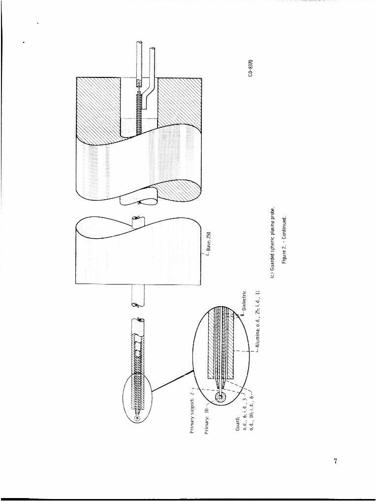
The probe geometries are shown in figures 1 and 2. Except the probe size the diameters in the overall assembly (fig. 1) are between 0.25 inch for the actuator tube and 1.155 inches for the bellows. With this bellows, a 2.2'75-inch vacuum-tight stroke can be made. The movement is alined through the 0.5-inch-diameter guide section and the entry port in the vacuum nut on the end. When the nut is welded to a metal tube in which a plasma is to be contained, the adapter package can be screwed in to deform two copper
During storing and shipping the internal gasket is replaced by a copper disk. With 5ao-Gro. - "17.4ri 'I?IGE, the tz-msh+~hle 3 r d ~ is sealed into the environment of the plasma.
this disk contaminants are excluded from the inside of the package after it is heated in a vacuum. A stay rod that is not shown is used to prevent the fragile probe from being pushed against anything. When the adzpter package is in ?lace a d the stay rod is re- moved, the probe can be inserted safely into the tube for the plasma. If these precautions are not taken, the probes can be destroyed easily; their insulating supports a r e only 45 mils for thermocoupled and 25 mils for nonthermocoupled versions.
tails of the guarded plasma probes. Here thermocoupled planar (fig. 2(a)), spheric (fig.
3
Yet in figure 2 the insulating supports appear to be much larger than the other tip de-

m
v) m n.
E -
L 0) c Q m w
4

W
0 3
5

M
6 v) m M
-4
N c I m 2 m
n d M
ai - 0 .c b 3 c m
6
a V
7

8

. n n
d e n 0
9

2(b)), and cylindric (fig. 2(d)) and nonthermocoupled spheric (fig. 2(c)) and cylindric (fig. 2(e)) probes a r e shown. Diameters a r e specified in the drawings, but lengths a r e left to be determined for particular applications. For example, in a good design more or less of the guard is exposed as thicker or thinner sheaths on the insulating support a r e ex- pected. Local measurements and small disturbances, however, are favored by short lengths as wel l as small diameters consistent with effective probe geometries.
The general structure of the probes is one of alternate concentric rings of conductor and insulator. Even the thermocouple w a s initially a single central wire of tungsten which was coupled with the nickel primary. Later this arrangement was changed to a Chromel- Constantan thermocouple in a 2-hole, 3-mil quartz tube (ref. 15). In each probe the guard is nearly touching the base of the primary. Between these electrodes, a gap is inter- posed to replace the usual insulator upon which charge is collected, a floating potential is developed, and a sheath is built up. The insulating support is also made to stand away from the guard. These narrow intervening spaces are intended to quench the plasma in- ternally. In addition, the gaps prevent the collection of wall currents when films of con- ducting material a r e condensed from certain plasmas on the insulating supports. A s a result, the guard, and not the primary, is affected by any edge effects.
The guard is also essential for continuing the geometry of the primary to allow the probe a rea to be defined. The latter function is successful in the plane probe, where the face of the primary is extended by the guard. Such extensions can also be built into large spheric and cylindric probes. In these small spheric and cylindric geometries, though, the guard is effective in defining the a rea only when the probe voltage is near the plasma
Detector
I d 3 Amplifier
I Primary Detector
resistance - probe
Figure 3. - Probe power and instruments.
potential. But this capability is an improve- ment over nonguarded probes; their areas are always distorted by the wall sheaths of the in- sulating supports.
With these comments and figures 1 and 2 the description of the probe geometries is com- pleted. But because this new plasma probe is composed of a primary, a secondary, and a thermocouple, extra attention is required fo r the power supply and instruments.
PROBE INSTRUMENTS AND POWER
The probe system is an assembly of elec- tronic shelf i tems (fig. 3). Some of these de- V i c e s a r e used to generate a nearly 100-volt
10

triangle wave with a bias and frequency that can be varied. Others are used to detect minute probe currents, to isolate and amplify thermocouple signals, and to synchronize and display guard and primary currents and temperature as functions of probe voltage.
This signal can be made to carry up to 40 milliamperes at 90 volts peak-to-peak with fre- quencies from to cycle per second. In the middle of the figure are the ampli-
3 fiers that are used to enlarge the signals listed on the right by factors up to 10 . These amplified data are displayed on oscilloscopes each having two traces.
the potentials of either the emitter in the direct-current arc o r the collectors in the plas- ma ionized by electron bombardment (fig. 4).
tions; for example, the measurements were lost initially in noise. But extensive shield- ing and grounding were found to remove this problem. Then only the difficulties of the probes were left.
On the left side of figure 3 are the components used to supply a biased triangle wave.
I The currents and temperature are shown for probe potentials that are varied about
I Although the probe and plasma systems seem simple enough, there were complica-
Argon
Figure 4. - Test plasmas for probes.
nnhnr n r r i i f TC rKUDC nC3ULI J
The important contributions of this work are shown in figures 1 and 2. These small yet complex plasma probes with guards and thermocouples have been made. If larger versions are required for particular conditions, the problems of assembiy are iess mfi- cult. But as it w a s stated previously, available refractory tubes were not small enough. The probes were constructed, therefore, of an alumina external tube, nickel tubing, a ceramic cement, and the thermocouple elements. And again, though these materials were suitable to demonstrate the fabrication and operation of the probes, they are not resistant
11

to high temperatures and alkali metals. Furthermore, the great thermal expansion of nickel is in opposition to putting the probe elements together and keeping them together during temperature changes. As a result, the probes were ruined by thermal effects be- fore the conditions and instruments could be adjusted in many tests.
Some data were collected, however, which can be used to show how guards and ther- mocouples a re essential to plasma probes. These added elements are intended to remove or solve the problems of edge and thermal effects. Therefore, simple interpretations of some data are given here t o demonstrate the functions of the guards and thermocouples, not to exhibit detailed probe results for various plasmas.
In figure 5 measurements are shown that were made with a plane probe (fig. 2(a)) in an electron bombardment plasma of argon (fig. 4, bottom). Temperatures (figs. 5(a) to (d)), primary (fig. 5(e)) and guard currents (figs. 5(a) to (e)), and calibrations are given for probe potentials that were varied at 0.1, 1, 10, and 100 cps from -75.5 to 25.5 volts relative to the collector screens. While the data were taken, the probe tip was cen-
1 tered radially and axially between the screens. These anodes were 35 centimeters in di- ameter, 10 centimeters apart, and 2 centimeters from their cathodes. The emitters were taken from 872A rectifier tubes made without mercury and were each heated with 8 amperes. In the direct-current arcs , 3 .3 amperes each were maintained when the volt- age drops were 32 volts for the discharge near the argon inlet and 9 volts for the other discharge. During this test the pressure was held at 40 microns of mercury.
From experience, it seemed probable that the nickel probe would have a short life- time. Therefore, two different amplifications were used for the guard and primary cur- rents to ensure at least partial success of the experiment. The circuits for the thermo- couple at 1 millivolt for each large division and the guard at 5 ~ 1 0 - ~ ampere per division were adequately set (figs. 5(a) t o (d)). With 5 ~ 1 0 - ~ ampere per division, however, the primary probe curve (fig. 5(e)) was not extended enough to analyze properly. Before the second series of tes ts with higher amplification the probe was destroyed by thermal ef- fects.
Prior to a discussion of the temperature data the plasma conditions might be esti- mated. Because the primary curve appears worthy of nothing elaborate, the simple Langmuir probe theory will be used. The validity of this approach will be indicated by the results.
In figure 5(e) the curve fo r the guard is shown above that for the primary. The line for the electron current at the top of the primary curve and its break into the transition region are quite clear. That knee can be used to compute the plasma potential (the no- sheath, total-random -current point):
*
I
I
l
2.1 8.7
Vo = 25.5 - - (25.5 + 75.5) = 1.1 V
12

(a) Thermocouple and guard traces. Voltage cycle frequency, 0.01 cps; temperature variation, AT = 28" C.
(b) Thermocouple and guard traces. Voltage cycle frequency, 10 cps; temperature variation, AT - 2" C.
(c) Thermocouple and guard traces. Voltage cycle frequency, 1 cps; temperature variation, AT = 10" C.
(d) Thermocouple and guard traces. Voltage cycle frequency, 1 0 cps; temperature variation. AT - 0" C.
l e ) Primary and guard traces. Voltage cycle frequency. 10 Cps.
bombardment plasma to s h w temperature variations wi th voltage cycle frequency for plane probe.
Figure 5. - Thermocouple. primary, and guard traces for r u n s in an electron
13

(a) Plasma held at 35.3 volts, 3 amperes, and 23 microns of mercury.
(b-1) Guarded
(b-2) Unguarded.
(b ) Plasma held at 41 volts, 0.9 ampere, and 2 microns of mercury. Voltage cycle frequency, 100 cps.
Figure 6. - Cyl indric probe with and without guarding in a hot-cathode d i rect -current argon arc 12 centimeters long in an 8-centimeters-diam- eter tube.
Another characteristic of the primary curve should be pointed out. The unblurred, exactly horizontal line at the bottom left is due to am- plifier saturation, not ion saturation. There is a slight bend in the probe curve 15 volts be- low the plasma potential, however, where the current is nearly zero. But this leveling ten- dency of ion saturation was apparently over- whelmed by some prebreakdown mechanism (refs. 16 and 17). As the voltage was made more negative, greater ion currents were ob- served. If the potential became too negative, a bright discharge was noted at the probe tip.
A second anomaly was responsible for separating the probe trace into two nearly par- allel curves in the ion-saturation and transition regions. This splitting was recorded for the guard as the voltage-cycling frequencies were increased to 100 cps (fig. 5(d)). The hystere- sis was probably the result of the resistance and capacitance of the positive-ion sheath (refs. 18 and 19). A s the voltages were changed rapidly, the currents and the structure of the sheath were unable to shift quickly enough to follow the same curve for both rising and fall- ing potentials.
Although the separation effect might be the product of instrumentation problems, several pieces of evidence a r e alined against this con- clusion. First, the same instruments, power supplies, and leads to the probe tip that were used for figure 5(d) at 100 cps were utilized in obtaining the data at 100 cps for figure 6. The latter curves are not split. Next, the hys- teresis (fig. 5(d), 100 cps) became less as the prebreakdown mechanism became more effec- tive. Then ionization and recombination were occurring within and around the probe sheath. Therefore, ions were made or lost as they
14

were required, charging and discharging the sheath internally and avoiding the lag to bring in or return plasma ions. Finally, if the sheath of positive ions was the cause of the curve separation, the hysteresis should have terminated at the plasma potential where no sheath exists. This closing of the curve is near the plasma potential. But these are data for the guard, which was always in contact with the sheath of positive ions of the insulating support. The probe curve for the primary, which was shielded from the sheath d the in- sulating support, began to split near 1000 cps.
This phenomenon is interesting as a diagnostic tool for cylindric probes. These probes are unable to give curves with sharp breaks at plasma potentials. By increasing the frequency of probe-voltage cycling to the point d curve splitting, however, the opera- tor might estimate the plasma potential as the end d the hysteresis loop near electron saturation. Such a technique seems as good as many that are now used. Of course, the cylindric probe should be equipped with a guard to avoid effects of the ion sheath of the
But these observations are delaying the proposed calculations d plasma conditions for the plasma d figure 5. Calibrations for the f u l l 101-volt cycle were compared at all potential-cycling frequencies to assure their applicability. From these calibrations the electron saturation current was found to be
insulating support.
(2) 4 = 2.55X10- A ie
The primary area was
(3) 2 2 2 Ap = ~(0 .01 ) (2.54) = 2.03~10-~ cm
Theref ore,
Because a semilogarithmic plot d the Maxwellian transition is impractical, another ap- proach to the electron temperature seems necessary. The following relation can be used if the distribution is Maxwellian:
(5) dvP
i dV - P KTe
The slope of the Maxwellian transition for the primary curve (fig. 5(e)) in the region of
15

. electron saturation is approximately
5 di : = 5.65X10- A/V
dvP
This rate (6) and the electron saturation current (2) can be used in equation (5) t o estimate the electron temperature:
1
i dVp
di Te = 11 600 - x 52 400' K = 4 . 5 eV/electron (7) I
Then, the electron number density is given by
15 If the gas temperature were 386' K at a pressure of 40 microns of mercury, 10 trals would occupy a cubic centimeter of such a plasma. This type of ionized gas would be similar to the Lorentz electron and atom model (ne << nn, me << m,), where the temperature of the neutrals should be low, of the order of 386' K. In such a gas colli- sions of electrons would be primarily with neutral atoms. The mean free path for these encounters between electrons and atoms should be near
neu-
V ~ 0 . 2 2 cm (9) - e - he, - - - -
V ea mn{
where dn is the cesium atom diameter ( ~ 3 . 8 ~ 1 0 ' ~ cm). This length is in contrast with
and 21). But of course, mean free paths near to o r greater than the plasma dimensions lack significance. For this test, therefore, the length separating collisions of electrons with atoms (eq. (9)) must be considered in the selection of probe dimensions. Because the probe diameter is about half of the smallest mean free path, replenishment of the dis- tribution is partially blocked, and the measured electron number density is probably slightly low.
Langmuir theory is applicable. Because there is no sheath at the plasma potential, the
average distances between coulombic collisions of the order of 10 3 centimeters (refs. 20
When the distance between collisions is large compared with the sheath thickness, the
16

' point for which these calculations were made, the assumption of no collisions was ful- filled. It might be wise, though, to check how the sheath thickness could vary through the Maxwellian transition to the floating potential, where the wall sheath is present. The distance through the wall sheath, which maintains the plasma, is assumed to be of the order of a Debye length:
B
The value obtained is much smaller than the smallest computed mean free path for elec- trons. The Debye length is also less than one-sixth of the overall active probe diameter. Thus, within the limits d the assumptions, the Langmuir theory should be a good apprax- imation.
For the plasma with properties given by equations (7) and (8), temperature data taken with the Chromel-Constantan thermocouple in the planar primary are shown in figures 5(a) to (d). The probe was operated at 0.1, 1, 10, and 100 cps from 24.4 to -76.6 volts relative t o the plasma. The thermocouple circuit was set to amplify by 10 ; thus, 14' C was spread vertically over one big division.
The probe temperature for 0.1 cps (fig. 5(a)) was terminated on the right at 29' C for 24.4 volts. There the probe was receiving the random electron current. At the left end d the loop the temperature was near 53' C for -76.6 volts, where accelerated ions heated the probe. Apparently ion currents that were created by the previously mentioned prebreakdown mechanism were responsible for much of the temperature rise. Usual thermal inertial effects were the cause d the maximum of 55' C and the minimum d 27' C, an overall change of 28' C. This difference was lowered through 28', loo, 2O, and 0' C as the probe-voltage frequency was raised through 0.1, 1, 10, and 100 cps.. But the average temperature was changed only a few degrees upward as the frequency was in- creased from 0.1 to 100 cps.
In the series shown in figure 5, thermal effects are emphasized even though the data were collected from a plasma with little heating tenciency. Fi'Obe sirfazes are dtered with temperature changes, and the resulting differences in contact potential between the probe and the plasma are sources of error. Many plasma devices a r e run with high tem- peratures, great thermal gradients, and condensing gases. When probes are needed in these conditions, thermocouples can be used to correct for o r to avoid iarge tnermal ef- fects. Furthermore, with the right geometry or proper calibration, a thermocoupled probe can be used to estimate overall energy transport in a plasma.
In any event, the thermocouple is necessary to follow o r to fix probe temperatures. But the guard is even more essential. If the probe is operated in an ionized gas contain-
1
3 I
1 4 I
1 I
L
I
17

ing a conducting material that is condensing, the guard is a shield against wall currents. However, many important plasmas are made up of gases that are neither condensable nor conductive at wall temperatures. Then the guard can only be used to separate the primary from the floating potential and the wall sheath of the insulating support. These base ef- fects are important in plane probes; cylindric versions, though, are made long com- pared with their diameters to reduce end er rors . Operating a cylindric probe at constant plasma conditions first with the guard disconnected and then with the guard at the primary potential should test shielding against the voltage and sheath of the support.
Figure 6 gives the results obtained with the guard either isolated or connected to the voltage of a cylindric primary. The thermocoupled probe was centered axially and radi- ally in a direct-current hot-cathode a r c of argon (fig. 4, top) 12 centimeters long in an ungrounded metal tube 8 centimeters in diameter. When the probe voltage was cycled in a hundredth of a second, the problem of temperature variation was removed. While the plasma for figure 6(a) was held at 35.3 volts, 3 amperes, and 23 microns of mercury, the probe was driven from 5.9 (left) to -5.1 (right) volts relative to the emitter. The heavy curves are data for the guard at primary potential, which can be compared directly with results for the disconnected guard shown by the light lines.
tive wall potential at the base of the probe. This shift is approximately 0.4 milliampere, but the relative change is great enough to reveal the problem. Although the end effect seems to be confined to the electron collection region in figure 6(a), situations can be found to show guard contributions near ion saturation.
For example, figures 6(b) and (c) were obtained for the probe and plasma tube of fig- ure 6(a) in a direct-current hot-cathode a rc of argon. Here, though, the data were taken at primary voltages near the floating potential with operating conditions changed to 0.9 ampere, 41 volts, and 2 microns of mercury. The right ends of the t races are 10.9 volts below the emitter with the left ends of the curves 13.4 volts above the emitter but slightly out of the photographs.
In figure 6(b) the curve for the guarded primary is seen to break abruptly away and to slope sharply downward from the nearly horizontal line for the ion current. In figure 6(c) the trace for the unguarded primary is shown to curve slowly away and to slant gently downward from ion saturation. Actually, the primary data of figure 6(c) are much like the guard data of figure 6(b). This similarity might be expected because both results were influenced by floating potential and wall sheath. Even in this probe curve the ion current is changed little from the guarded to the unguarded primary, but ion currents are gener- ally near zero. Shielding, however, is responsible fo r major differences in the Maxwel- lian transition near ion saturation.
When these errors in the transition and electron saturation regions are not removed by a proper guard, the two best measurements of the Langmuir probe are jeopardized.
'
Without shielding, the electron current of the primary is lowered because of the nega-
18

. e
From these data the electron temperature and number density are computed. Thus, guards are needed by plasma probes even when wall currents are not problems, and ther- mocouples in primaries are necessary to correct probe data or to avoid such adjustments by isothermal operation and to obtain additional information.
For these reasons, guards and thermocouples are essential if plasma probes are re- quired to determine local properties in ionized gases. The minute plasma probes devel- oped in this work, however, are not resistant to alkali metals and high temperatures. But a prototype of tantalum and alumina has been made and cycled without failure for hours in a plasma that the nickel probes would not have survived long. Unfortunately, this new cylindric probe was equipped with a faulty thermocouple. Development of re- fractory probes is continuing.
CONCLUDING REMARKS
Ionized gases are changed by Langmuir probes. Part d this transformation is caused by the insulating support with its floating potential and wall sheath. The floating potential and the wall sheath are also immediately adjacent to the base of the probe itself. Thus, the usual Langmuir probe is a wire extending from a negatively charged insulator through a positive ion sheath into a plasma altered by the presence of a foreign body.
Of course, any attempt to make a truly local measurement is expected to affect the ionized gas. But if this kind of testing is necessary, it should be done accurately. Minute plasma probes with guards and thermocouples can be used to obtain data corrected for thermal and base effects. These probes are also small enough to cause little more dis- turbance than conventional versions and to take spatially discrete data in many plasmas.
Lewis Research Center, National Aeronautics and Space Administration,
Cleveland, Ohio, July 14, 1966, 123-33-02-09-22.
REFERENCES
1. Suits, C. G. , ed. : The Collected Works of Irving Langmuir. Vol. 4, Electrical Dis- charge. Pergamon Press, 1961. Von Engel, A. : Ionized Gases. Oxford Univ. Press, Inc., 1955. Cobine, J. D. : Gaseous Conductors, Theory and Engineering Applications. Dover Pub., Inc., 1958. Anderson, T. P. ; Springer, R. W. ; and Warder, R. C., Jr., eds. : Physico-Chemical Diagnostics of Plasmas. North- western Univ. Press, 1963. Extended series of papers by longstanding experts such
19

?
as K. G. Emeleus and G. Medicus. Many current research and development papers in journals of physics and electronics.
2. Loeb, Leonard B. : Basic Processes of Gaseous Electronics. Univ. of California Press, 1960.
3. Seitz, Frederick: Modern Theory of Solids. McGraw-Hill Book Co., Inc., 1940.
4. Suits, C. G., ed. : The Collected Works of Irving Langmuir. Vol. 4, Electrical Discharge. Pergamon Press , 1961.
5. Nottingham, Wayne B. : Thermionic Emission. Rept. No. 321, M.I . T . , Dec. 10, 1956.
6. Moore, George E. ; and Allison, H. W. : Adsorption of Strontium and of Barium on Tungsten. J. Chem. Phys., vol. 23, no. 9, Sept. 1955, pp. 1609-1621.
7. Gavrilyuk, V. M. : Influence of Adsorption Film of Atoms of Barium and Molecules Ukrain. Fiz. of Barium Oxide on the Energy of Escape of Electrons from Metals.
Zhur., vol. 1, no. 1, 1956, pp. 73-80.
8. Ranken, W. A.; Aamodt, R. L.; Brown, L. J . ; andNichols, B. D.: Experimental Studies of Cs-CsF-Mo and Cs-CsF-W Plasma Diode Emitters. Adv. Energy Con- version, vol. 3, no. 1, Jan. 1963, pp. 235-244.
9. Tower, Leonard K. : The Erected Dipole Model in the Adsorption of Cesium on Fluo- rinated Molybdenum. NASA TN D-3223, 1966.
10. Aisenberg, Sol: Modern Probe Techniques for Plasma Diagnosis. Third Engineering Aspects of Magnetohydrodynamics Symposium, Norman W. Mather and George W. Sutton, eds. , Gordon and Breach Sci. Publ., 1964, pp. 89-126.
11. Bullis, R. H. : Electrostatic Probe Measurements in a Cesium Plasma. Adv. Energy Conversion, vol. 2, July-Sept. 1962, pp. 523-526.
12. Cobine, J. D. : Gaseous Conductors, Theory and Engineering Applications. Dover Publications, 1958.
13. Dotson, J. P.; and Janes, G. S. : Use of Guard Ring Shields on Negatively Biased Langmuir Ion Collection Current Probes. Rept. No. AMP- 137, Avco-Everett Res. Lab., Apr. 1964.
14. Morris, J. F. ; Tischler, R. F.; and Beckman, p.: Plasma Probes. U.S. Patent Application Serial No. 489,442.
15. Anon. : HT Micro-Miniature Thermocouples. Baldwin-Lima-Hamilton Corp. , Nov. 1965.
Product Data 205-1, Electronics Div. ,
20

r ,
0
16. Loeb, Leonard B. : Secondary Processes Active in the Electrical Breakdown of Gases. British J. Appl. Phys., vol. 3, Nov. 1952, pp. 341-349.
17. von Engel: Ionized Gases. Oxford at Clarendon Press, 1955.
18. Appleton, E. V.; and Childs, E. C. : On Some Radio-Frequency Properties of Ion- ized Air. Phil. Mag., ser. 7, vol. 10, no. 67, Dec. 1930, pp. 969-994.
19. Anderson, T. A.: Dynamic Probe Characteristics. Phil. Mag., ser. 7, vol. 38, no. 278, Mar. 1947, pp. 179-185.
20. Spitzer, Lyman, Jr. : Physics of Fully Ionized Gases. Interscience Publishers, 1962.
21. Thompson, W. B. : An Introduction to Plasma Physics. Pergamon Press, 1962.
NASA- L.inglrv 1966 E -3 29 1 21
-