search.jsp?r=19690030758 2019-09-30t18:28:53+00:00z · for example, the directive gain is less than...
TRANSCRIPT
https://ntrs.nasa.gov/search.jsp?R=19690030758 2020-01-06T01:18:25+00:00Z


DIRECTIVE G A I N OF CIRCULAR TAYLOR PATTERNS
D.C.F. Wu and R.C. Rudduck
TECHNICAL REPORT 1691-32
Grant Number NGR 36-008-005
August 12, 1969
National Aeronautics and Space Administration Of f ice o f Grants and Research Contracts
Washington, D . C . 20546
ABSTRACT
The d i r e c t i v e gain o f c i r c u l a r Taylor patterns i s determined. It is shown t h a t so-cal led optimum patterns, i.e., uniform sidelobes i n a l l planes, are severely l i m i t e d f o r planar apertures because o f excessive sidelobe power. I t i s shown tha t optimum d i r e c t i v e gain o f the c i r c u l a r Taylor pa t te rn w i t h a given sidelobe leve l can be obtained by appropriate design. Two parameters, A , a quant i t y uniquely re la ted t o the design sidelobe leve l and ii a number c o n t r o l l i n g the degree o f un i formi ty o f the sidelobes have been determined t o achieve the optimum d i r e c t i v e gain.
ii

CONTENTS
Page
I. INTRODUCTION
11. DIRECTIVE GAIN ANALYSIS FOR CIRCULAR APERTURES
A. B.
C.
Radiat ion Pat te rn Functions D i r e c t i v e Gain Ca lcu la t ion 1. Idea l Tay lo r D i s t r i b u t i o n 2 . Tay lor d i s t r i b u t i o n Results
(Dol ph-Chebyshev)
111. CONCLUSIONS
REFERENCES
1
2
9
10
iii
DIRECTIVE GAIN OF CIRCULAR TAYLOR PATTERNS
I . INTRODUCTION
The dire'ctive gain of the circular Taylor pattern is examined i n this publication. The radiation pattern of the Taylor distribution has a specified number of equal level sidelobes followed by tapered lobes. T h i s research was motivated by consideration of the design of large ground based antennas fo r space communications.
Over the past two decades of antenna research, considerable a t - tention has been devoted to the design of h i g h gain, narrow beam antennas. I t is well known that the Chebyshev pattern gives the optimum beamwidth t o sidelobe level relationship. The true Chebyshev patterns are applicable only t o arrays, not to continuous aperture distributions. Furthermore, the continuous aperture equivalent of the Chebyshev or the ideal Taylor pattern i s not physically realizable. However, Taylor1 introduced a physically realizable pattern which i s obtained by approximating the Chebyshev or ideal Taylor pattern by nearly equal sidelobe level out to a t ransi t ion point K, beyond which the sidelobe level is tapered as sin ( x ) / x . As Taylor pointed out, the ideal space factor can be practically approximated by choosing the transit ion point i i w i t h i n the visible region, t h u s avoiding supergain. throughout the vis ible region are not optimum w i t h respect t o directive gain.
patterns, and has shown the limitations of long l ine sources. are also applicable t o rectangular planar apertures for which the pattern I's the product o f two perpendicular Taylor l ine sources. l a t t e r do not have the optimum beamwidth t o sidelobe level relationship, because even the near sidelobes are depressed outside the principal planes. The c i rcular Taylor pattern by i t s circular symmetr approximates the optimum beamwidth to sidelobe level relationship.398 Tseng and Cheng5 have also derived the uniform sidelobe pattern (optimum Chebyshev pattern) fo r a rectangular planar aperture which i s optimum w i t h respect to the beamwidth t o sidelobe level relationship.
However, patterns w i t h nearly uniform sidelobes
2 Hansen has determined the directive gain fo r Taylor l ine source His results
However, the
In this paper directive gain is determined fo r the circular Taylor patterns, including both approximate and ideal Taylor space factors , i .e., only the omnidirectional element pattern is considered. I t is shown tha t the optimum Chebyshev (uniform sidelobes i n a l l planes) o r the ap- proximation t o the ideal Taylor space factor (nearly uniform visible sidelobes) is more severely limited fo r planar apertures, e i ther rec- tangular o r c i rcular , than fo r l ine source apertures. For example, a 20 dB sidelobe level design w i t h t ransit ion point near the edge of the visible region gives poor directive gain fo r c i rcular apertures which exceed 1 0 ~ i n diameter whereas a line source may be useable to 1 0 0 ~ . Further, i t i s seen tha t maximum directive gain of the circular Taylor pattern is achieved for a given sidelobe level by appropriate choice of t ransi t ion point E.
1
11. DIRECTIVE GAIN ANALYSIS FOR CIRCULAR APERTURES
A. Radiation Pattern Functions
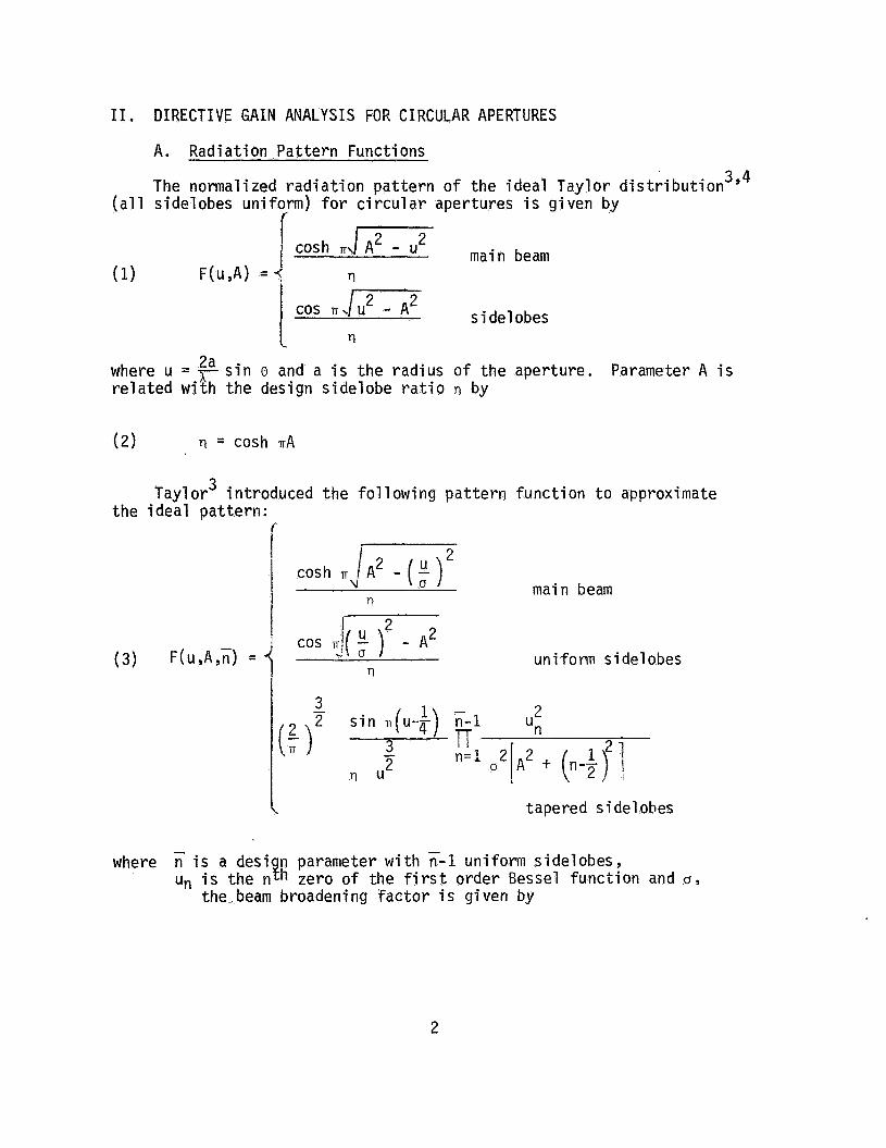
The normalized radiation pattern of the ideal Taylor d i ~ t r i b u t i o n ~ ’ ~ ( a l l sidelobes uniform) for c i rcular apertures i s given by
f
2 1 Gosh R J A 2 - u main beam (1) F(Li,A) =i n 1 ‘Os nm sidelobes
n 2a where u = r s i n e and a i s the rad ius of the aperture.
related w i t h the design sidelobe ra t io Q by Parameter A i s
3 Taylor introduced the fo l l owing pattern function t o approximate the ideal pattern:
’ COS IT!( 2 2 ) - A uniform sidelobes u
I rl
1
t tapered s i del obes
where is a desi n parameter w i t h n-1 uniform sidelobes, U n i s the nyh zero o f the f i r s t order Bessel function and cry
the,beam broadening factor is given by
2
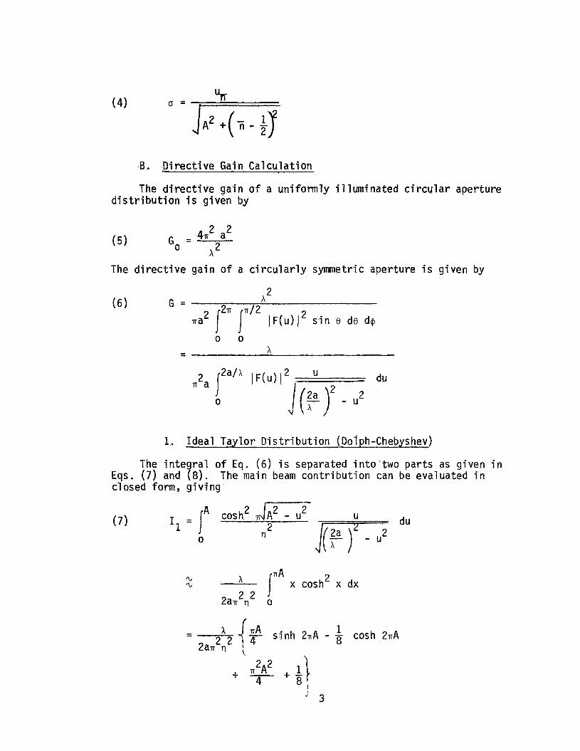
B. Directive Gain Calculation
The directive ga in of a uniformly illuminated circular aperture d i s t r i b u t i o n i s given by
2 2 - 471 a (5) Go - , 2
A
The directive gain o f a circularly symmetric aperture i s given by
2
0 0
1. Ideal Taylor Distribution (Dolph-Chebyshev)
The integral o f E q . (6 ) is separated i n t o two parts as given i n E q s . ( 7 ) and ( 8 ) . closed form, g i v i n g
The main beam contribution can be evaluated i n
(7 ) I1 = I" 0
cos h A F T 2 n
du
2 A ITA x cosh x dx 'L 'L
v2A2 + .\ 8 f - 4

The sidelobe contribution i s given by
2a’A cos2 ITJ u2 - A2 2
0 (8) U
p- du
A r n
2 - - (I(F)L-A2 x 1 r . cos ITX dx
J 0
2J(:)L-A 2 2 - x rl
1-
The l a s t integral can be readily evaluated since ~ 1 - y ~ defined, slowly varying function. The numerical technique used con- sists basically of summing maximum values of the slowly varying modulus o f the rapidly osci l la t ing sinusoidal function times the area under one lobe of the sine function. Hence the directive gain of the circular Taylor distribution i s given by
i s a well
2. Taylor distribution
The gain o f the circular Taylor distribution can be calculated i n a similar manner. mated by us ing the beam broadening factor a, g i v i n g
T h e main beam contribution can be accurately approxi-
I 3
du
4

The contribution of the uniform sidelobe region can be approximated i n closed form i f less than 1 /2 of the visible sidelobes are uniform; i . e . , W < a/x. T h i s gives
The con t r ibu t ion o f the tapered sidelobe region i s given by
where
The integrals o f Eq. (12) can also be accurately evaluated by numerical integration. Hence the gain of the Taylor distribution is given by
x (14) G = 
2 a a(T1 + T2 + T3)
where T1, T2 and T3 are given by Eqs. (10) t o (12) respectively.
5

C . Results
Values of normalized directive gain for c i rcular Taylor patterns are given i n Table I for various sidelobe rat ios and fo r various tran- s i t ion values Ti ranging from 3 t o 10. I t is t o be noted that the normalized gain does not vary for large circular apertures, say a > 1 O A . The transit ion point T i is chosen t o be less than a/h (less than harf of the sidelobes are uniform) due to the approximation i n Eq. (11). How- ever, for normalized directive gain approaches tha t of the Taylor Ideal c i rcular patterns
> a/A (more than half of the sidelobes are uniform), the
The normalized directive gain o f various sidelobe rat ios of the ideal c i rcular Taylor patterns i s plotted i n F i g . 1 as a function of aperture radius a. I t is noted that the directive gain of the ideal pattern (or practical distributions w i t h more than 1/2 of the vis ible sidelobes uniform) i s severely limited for large planar apertures. For example, the directive gain is less than 30% of that available froin a uniform aperture distribution for aperture diameters 2a > lox (20 dB sidelobes or higher), o r 2a > 30x (30 dB sidelobes or h i g h e r ) . As evident from the figure the normalized directive gain for a fixed sidelobe level decreases rapidly w i t h increasing aperture s ize . The useable range i s considerably greater f o r the line source case, e.g., the normalized directive gain of an ideal Taylor l ine source w i t h 20 dB sidelobes is greater than 50% for lengths u p to 100h.2
As seen from Table I , appropriate choice of the transit ion point ii yields a maximum value fo r the directive gain of the circular Taylor pattern w i t h a given sidelobe design. values and corresponding ii values are given i n Table 11. directive gain is not particularly sensit ive t o choice of K, substantial departure from optimum K will resul t i n decreased g a i n . gain represents a tradeoff between beam w i d t h and sidelobe power. As ii is increased the beamwidth decreases, tending t o increase gain; however, sidelobe power also increases, t h u s l i m i t i n g the maximum value of d i - rective gain.
These optimum directive gain Although the
O p t i m u m directive
For comparison the optimum directive g a i n fo r the rectangular planar aperture (two perpendicular Taylor l ine sources) as determined by Hansen2 is also shown i n Table 11. rective gain fo r the circular aperture i s higher than that of the rectangular aperture, especially for larger sidelobe rat ios .
I t i s noted that the optimum d i -
6

I .o
0.8
0.2
UNIFORM DISTRIBUTION I
20 de- n=3- - <
O5 I O I O 0 I O 0 0
Fig. 1. Normalized ga in vs radius of circular a p e r t u r e .
7

TABLE I
Si del obe level in dB 3
15 0.8752 18 0.9552 20 0.9614 22 0.9455 25 0.9032 30 0.8273 35 40
4
0.7266 0.8839 0.9327 0.9441 0.9185 0.8378 0.7602 0.6985
5
0.5838 0.7832 0.8713 0.9163 0.9210 0.8525 0.7695 0.6987
TABLE I1
S i del obe Circular 1 eve1 Optimum - i n dB Gain n
20 0.9614 3 25 0.9210 5 30 0.8679 8
6
0.4671 0.6782 0.7957 0.8691 0 .go90 0.8631 0.7806 0,7052
8
0.3074 0,4978 0.6325 0.7481 0.8536 0.8679 0.7982 0.7203
10
0.2130 0.3683 0.4960 0.6247 0.7757 0.8550 0.8072 0.7322
Rectangular 0 p t i mum Gai n n
-
0.941 9 0.81 18 0.5625 36
8
111. CONCLUSIONS
The directive gain i s evaluated f o r c i rcular Taylor dis t r ibut ions, both ideal and tapered space factors. The c i rcular Taylor patterns offer a practical approximation to the optimum beamwidth-sidelobe relationship for planar apertures.
I t is shown t h a t the so-called optimum patterns, i .e., w i t h a l l v is ible sidelobes uniform, are severely limited for planar apertures because of excessive sidelobe power. I t is also shown that maximum directive gain can be achieved for the circular Taylor pattern by appropriate choice of the number of uniform sidelobes. The optimum directive gain is found to be higher f o r the circular Taylor than for the square Tayl or pattern since the off -p r i nci pl e pl ane s i del obes are lower fo r the square Taylor.
9

REFERENCES
1.
2.
3 .
4.
5.
Taylor, T.T. , "Design of Line-Source Antennas f o r Narrow Beamwidth and Low Side Lobes ,' IRE Trans. on Antennas and Propagation, vol. AP-3, No. 1, January 1955.
Hansen, R.C . 9 "Gain Limitations of Large Antennas," IRE Trans. on Antennas and Propagation, vol . AP-8, No. 5 , September 1960.
Taylor , T .T. , "Design of C i rcul a r Apertures f o r Narrow Beamwidth and Low Sidelobes," IRE Trans. on Antennas and Propagation, vol . AP-8, No. 1, January 1960.
Hansen, R . C . , "Tab1 es of Tayl o r Distributions f o r C i rcul a r Aperture Antennas ,I' IRE Trans. on Antennas and Propagation, vol . AP-8, No. 1, January 1960.
Tseng , F. I . and Cheng , D . K . , "Optimum Scannable P1 anar Arrays w i t h an Invariant Sidelobe Level 9 " Proceedings of the IEEE , vol . 56, No. 11, November 1968.
10