search.jsp?r=19740019264 2018-09 … · preface.. the hughes aircraft company pioneer venus final...
TRANSCRIPT
https://ntrs.nasa.gov/search.jsp?R=19740019264 2018-09-26T23:20:57+00:00Z
00000001-TSA03
PREFACE
.. The Hughes Aircraft Company Pioneer Venus final report is based on
; study task reports prepared during performance of the "System Design Studyi _ of the Pioneer Spacecraft." These task reports were forwarded to Ames
: :.. Research Center as they were completed during the nine months study phase.
The significant results from these task reports, along with study results
developed niter task report publication dates_ are reviewed in this finali
report to provide complete study documentation. Wherever appropriate, thetask reports are cited by referencing a task number and Hughes report refer-
! .,
ence number. The task reports can be made available to the reader specific-i ally interested in the details omitted in the final report for the sake of brevity.
: This Pioneer Venus Study final report describes the following baseline,_ c onfigurations:
, - • "Thor/Delta Spacecraft Baseline" is the baseline presented at_:'" the rnidterrn review on 26 February 1973.
: • "Atlas/Centaur Spacecraft Baseline" is the baseline resultingfrom studies conducted since the midterm_ but prior to receipt
of the NASA execution phase RFP, and subsequent to decisions:__...
_. to launch both the multiprobe and orbiter missions in 1978 and" use the Atlas/Centaur launch vehicle.
_t2 _s/Centaur Spacecraft Midterm Baseline" is the baseline:. presented at the Z6 February 1973 review and is only used in the
launch vehicle utilization trade study•
,:i The use of the International System of Units (SI) followed by otherunits in parentheses implies that the principal measurements or calculations
' = were made in units other than SI. The use of SI units alone implies that theprincipal measuren=ents or calculations were made in Si units All conver-
- sion factors were obtained or derived from NASA SP-701Z (1969}.r
The Hughes Aircraft Company final report consists of the following• documents:
Volume l -.Executive Su_imary -provides a summary of the major: i-ssue-s_tnd de_s_oris re_tc_/ed d-uring the course of the study. A brief
: description of the Pioneer Venus Atlas/Centaur baseline spacecraft
and prcbes is also presented.
iii ]?RECEDING I AGI,, BLANK NOT FILMED
:' ' ' ...." ".............." 00000001-TSA04

.M
-_ Volume 2 -Science - reviews science requirements, documents the(_..,. science.*peculiar trade studies and describes the Hughes approach
i-= for science implementation.
Volume 3 - Systems Analysis - documents the mission, systems_operati0ns} gr0und systems S and reliabilityanalysis conducted on
; the Thor/Delta baseline design.
Volume 4 - Probe Bus and Orbiter Spacecraft Vehicle Stt,dies -: presents the configuration, structure_ thermal control and cabling_ studies for the probe bus and orbiter. Thor/Delta and Atlas/Centaur: baseline descriptions are also presented.
Volume 5 - Probe Vehicle Studies - presents configuration,i
ae amicand structure studies for the large and small probes: pressure vessel modules and deceleration modules. Pressure: vessel module thermal control and science integration are discussed.
Deceleration module heat shield, parachute and separation/despin,- ' are presented. Thor/Delta and Atlas/Centaur baseline descriptions
are provided.
"¢olume 6 - Power Subsystem Studies
• Volume 7 = Cornmt'"_cation Subsystem Studies
:- Volume 8 - C.ommand/Data Handlin_ Subsystems Studies
iil Volume 9 = Altitude Control/Mechanisms Subsystem Studies
- Volume I0 - Propulsion/0rbit lnsertign Subsystem Studies
Volumes 6 through I0 = discuss the respective subsystems for the:- probe bus, probes, and orbiter. Each volume presents the sub-: system requirements, trade and design studies, Thor/Delta baseline
descriptions_ and Atlas/Centaur baseline descriptions.
Volume II - Launch Vehicle Utilization = provides the comparisonBetween the Pioneer Venus spacecraft system for the two launch
i " vehicles, Thor/Delta and Atlas/Centaur. Cost analysis data is• ::
presented also.
! Volume 12 - International Co0_eration - aocurnents Hughes suggestedal-lternatiVes to implement a cooperative effort with ESRO for theorbiter mission. Recornmer_dations were formulated prior to the
! deletion of internat `)¬�¨�cooperation.
Volume 13 - Preliminary.LDevelopmcnt Plans - provides the
.... ' ' '.... " ..... 00000001 -TSA05
ttt
Volums 14 - Test Planning Trades -documents studies conducted to_e'termlne t_e desirabie testin-ga'pproach for the Thor/Delta space-craft system. Final Atlas/Centaur test plans are presented inVolume 13.
Volume 15 - Hughes IR_D Documentatioh - provides Hughes internal
,, documents generated ou independent' research and development moneywhich relates to some aspects of the Pioneer Venus program. Thesedocuments are referenced within the final report and are provided forready access by the reader.
Data Book -presents the latest Atlas/Centaur Baseline design in ani'nformal tabular and sketch format. The informal.approach is usedto provide the customer with the most current design with the finalreport.
V
...... ....... TSA06" 00000001-
l
/ ....
CONTENTS
Pa ge
1. SUMMARY I-I
I. I Major Issues I-II. 2 Baseline Design I-3
' 2. INTRODUCTION 2- 1
3. SUBSYSTEM REQUIREMENTS 3-I
3. 1 Mission Requirements 3-13.Z System Requirements 3- 1
: 3.3 Subsystems Requirements 3-8
4. TRADE STUDIES 4-1
4. i Probe Antennas 4-34.Z Probe Bus Antennas 4-I l
Medium Gain Antenna Selection 4- l 1i "loroidal Beam Antenna Selection 4-13
Spherical Coverage Antenna Selection 4-154.3 Orbiter Antennas 4-17
Electronically Despun Antenna (EDA) 4- 18Mechanically Despun Antenna (MDA) Array 4-21L
: MDA Reflector Antennas 4-28MDA-EDA Tradeoff 4-3 1
4.4 Power Amplifier Selection 4-35Solid State Amplifier Versus TWTA Tradeoff 4-35
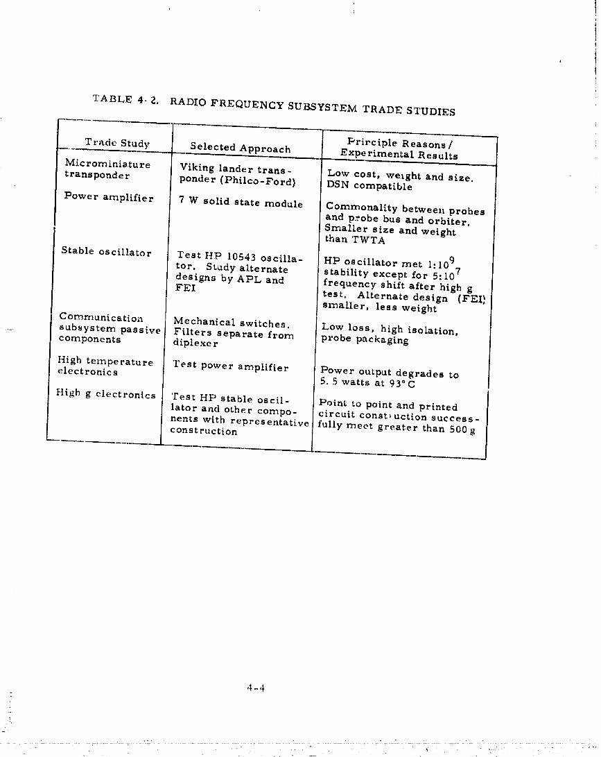
4. 5 Microrniniature Transponder Selection 4-394.6 Stable Oscillator 4-414. 7 Communication Subsystem Passive Cu..ponents 4-43
Switches 4-46Filters 4-47
: Rotary Joint 4-49Circulator-Isolator 4-49Coaxial Cables 4-49
4.8 Probe Environmental Considerations 4-51
High Temperature Electronics 4-51High-G Electror:ics 4-53
vii NG,
00000001-TSA07
[L
_ 5. THOR/DEI,TA LASELINE 5- !_, -_. 5. I Radio Frequency Subsystem 5-I_ Probe Bus 5- |i_ ' Orbiter 5-5'.;:. "_ I,arge Probe 5-9_. Small Probe 5-9[U 5.Z Antenna Subsystem 5- 13_:_ " O rbite r 5-13!i_ . Probe Bus 5-15'-t_ _ Large Probe 5-19!_ :- Small Probe 5-19
!- 6. ATLAS�CENTAUR BASELINE 6-I
h. ' 6. 1 Dual Frequency Occultation Implementation Trade 6-4' 6. Z Radio Frequency Subsystem 6-9_ i! Probe Bus 6-9_j _ Orbiter 6-9_ La rge Probe 6- 13
Small Probe 6-17
6.3 Antenna Subsystem Description 6-17_ Probe Bus Antenna Subsystem 6-17_i , Orbiter Antenna Assembly 6-23_-, P robe Antennas 6-Z 7
i2_ "I =
°,
2 '-
i
!.?,
i,
i -
- viii
00000001-TSAO
I. SUMMARY
I. I MAJOR ISSUES
Communications subsystem tradeoffs were undertaken to establish alow cost and low weight design consistent with the mission req,drements.Because of the weight constraint of the Thor/Delta launched configuration,minimum weight was emphasized in determining the Thor/Delta design. In
: contrast, because of the greatly relaxed weight constraint of the Atlas/Centat/rlaunched configuration, minimum cost and off the shelf hardware were empha-sized and the attendant weight penalties accepted. Commut:ication subsystemhardware elements identifiedfo_"study included probe and bus antennas (CM-6,CM-17), power amplifiers (CM-10), and the large probe transponder andsmall probe stable oscillator required for doppler tracking (CM-II, CM-16).In addition, particular hardware problems associated with the probe hightemperature and hig_t-genvirot.ment were investigated (CM-7).
Various antennas were considered for the large and small probesconsistent with the basic requirement of conical coverage at 45 • I0 deg forthe large probe and 60± I0 deg for the three small probes. Candidateantennas identifiedincluded the annular slot, turnstile, discone, archimedean
spiral, equiangular spiral and [oop-vee. The loop-vee was selected for thesmall probe and the equiangular spiral for the large probe because of theirminimum size and weight.
Because of the diverse requirements of the probe and orbiter mission,different antennas were selected (Task CM-12) for the probe bus and orbiter.For the selected spin axis orientatio, perpendicular to the ecliptic(TaskEX-IZ), probe bus communication during cruise required a toroidal beam.A bicone was chosen over a conical log spiral or radiator array as the mini-mum weight solution that would provide the required gain. Probe bus highdata rate science return at entry required gain concentrated along the aft spinaxis. An 18 dB medium gain horn was selected over an endfire radiator orradiator array for minimum system weigh_ and cost. The orb:.er require-ment of high gain perpendicular to the spin axis resulted in a trade of a mech-anically despun antenna (MDA) and an electronically despun anterr_a(EDA).An alternate azimuthal omnidirectiol,al design w,as eliminated dui to theattendant increase in required transrnitte_'power. Because of developmentstatus, demonstrated reliability on previous Hughes spacec-aft and flexibilityto varying requirements (in particular the potential addition of a dual fre-qtlency occultation requirement (Task CIvI-19)), the MD.& was selected. In
1-!
..... 00000001-TsA09

i •
addiffon to the high gain devices a pair of omni antennas were ir_ctuded(common to the probe bus and orbiter) to provide 4 Trsr command coverage.
* A conical tog sprial and slotted cone radiator was selected for low weight• and availability.
:i A comparison of solid state versus travelin_ wave tube amplifiers• was undertaken. A solid state a1_plifierwas chosen for minimum weight
and for commonality. A basic 7W module for the Thor/Delta spacecraft anda 9 W module for the Atlas/Centaur spacecraft was _sed as a building block
Z_ to meet the requirements of the probes, the probe bus, and the orbiter.
ii_ The science tracking reqt_irement of two-way doppler for the large: probe and one-way doppler for the small probe resulted in the study of avail-i ii able transponders for the large probe and stable _sciliators for the small
probe. Atransponder was also required for the probe bus and orbiter but_:. not as part of the science payload. For maximum commonality, the t:ans-! ponder selected to meet the large probe sci¢,ncerequirements was also
selected for the orbiter and probe bus. The Viking lander transponder was_ selected for the large probe based on hardware availability. The added cost
of repackaging the unit to modify its footprint on the shelf to reduce its impacton the large probe was accepted for the Thor/Delta design.
i - Three available stable oscillators were identifiedas applicable to thesmall probe require,nents. A Hewtett-Packard oscillator met all criteriai Y"
except for a frequency shiftexperienced after exposure to simulated entry- acceleration. An alternate Applied Physics Laboratory design was tighter,
smaller, and much less sensitive to shock, but exhibited inadequate short
_ term stability. The third design, by Frequency Electronics, Inc., demon-strated the required stabilityof one part in 109 when tested in the probe
!. acceleration and temperature environment. It was potentiallythe mosti__ stable design and by far required the lowest powe_.
A trade cf mechanical switching versus fertile or diode switchingi resulted in selection of mechanical switching based on low insertion loss andi '
i - high isolation A diptexer was chosen consistLng of a circulatr- and separatei . . e
- filtersas opposed to an integrated design because of higher acnievable isola-tion and easier packaging in the probes. The exciter output isolator waseliminated in the small probes for magnetic cleanliness. T.his resulted in a
i..... need to turn off the small probe transmitter during entry to avoid damagLr.gi :
reflections from the plasma sheath.i
i " High temperature performance was considered for criticalele heats- of the probe communication subsystem. In particl,lar,it was shown that the
transponder would have an acceptable noise figt_reat temperatures up to 70o C- at_d that the filters could function up tc 77°G. High-g periormance was
similarly considered. Point-to-point and printed circuit construction similarto those used in the power amplifier and transponder were shown to survive
- the ':,igh-glevels associated with entry. A perma,_ent frequency shiftwas' exhibited in the Hewlett-Packard oscillator requiring further study. The
large probe transponder and small probe exciter den_onstrated adeqtlate per-refinance when exposed to shock acceleration levels well above the 700 gqualification requiren_ent.
1-2
7
.... O0000001'TSAIO

- :( :
- ..
_ ,-!ii•..
: Selection of the Atlas/Centaur launch vehicle has directly benefited_!:,: : the communication subsystem design, principally in the resulting use of the ,_'_:; Viking lander transponder without modification. Itowever, updates of the-' mission set and science payload that were considered for the Thor/Delta ':._... have resulted in many additional changes in the final Atlas/Centaur baseline ij.:.... : design, In particular, the elimination of the small probe magneton_eter hasIY_: _ allowed the inch_sion of an output isolator. The increased large probe com-:-_.::: . corrunication angle and different small probe comtnunication angles bare;_:::_ resulted in the selection of an oronihemispherical antenna for all the probes,
•:- The omni reduces the sensitivity of the communication link to probe attitudel_:k_:: variation during the descent and allows use of a common antenna design for"i f :
_.:: _ large and small probes, The selection of dual frequency occultation for the....=-: nominal orbiter payload has resulted in the addition of an X-band transmitter_'. and horn and a dual channel rotary joint to the MDA. The increased space-- available for the fixed probe bus bicone antenna has led to the selection of a
.::.,_ larger bicone array to take advantage of the attendance increase in gain.!i ? - _ -
_ .:: A trade studies summary is presented in Table I-I.,:!'-
!: I.2 BASELINE DESIGN
The communication system consists of the radio frequency subsystemi-:: and the antenna subsystem. For the Thor/Delta configuration, these sub-}.:_i.'-? systems were designed for the lowest possible cost within the system weight: : " and performance constrair:ts. In particular, the greatest possible design
•++,7-'..... :-=. commonality and selection of developed hardware was emphasized whereverweight limitations would allow. ',"he relaxed weight constraint of the Atlas/
!:_: Centaur resulted in design changes to achieve greater commonality and_. increased use of developed hardware. Changes in the science payload and thei : i mission requirements that were not incorporated in the Thor/Delta baseline• .._ but were incorporated in the final Atlas/Centaur baseline account for addi-, tional differences between the two configurations.
, The Thor/Delta probe bus radio frequency subsystem consists of two!_" :" 7 W solid state power amplifiers, redundant preamplifiers/receivers and:' e:.citers,and the associated rf switches, transmit filters_and diplexers.', +, :. Three rf power operating modes are incorporated in the power amplifier_i :i .... and summing hybrid design° Ten rf W output power can be d_livered through
: the bicone_ medium gam horn, or widebeam omni. Five or one W can bei delivered through any antenna from either power amplifier. Redundant low
noise preamplifiers and the Viking transponder are connected through the• i
, diplexer to either omni for the receive function. >
......:" The Thor/Delta orbiter rt"subsystem is identicalto that of the probe?, bus except for changes in the switching arrangement necessary to accommo-: : date the different antenna complement. In particular, the orbiter has only
.- three antenna instead of four. Ten, five and one rf W output power levels can•:. be delivered to the high gain antenna or widebeam omni and, as in the probe
bus_ the narrowbeam (spinning) omni can transmit only the 5 and 1 W modes,
: .... 1-3
i '%_ .
y+
" 0 0----.----+000001/5A1 1
TABL_ I-1, TRADE STUDIES SUMMARY
Thor/J:)e|ta
L Bmaaline
Iaa_e ConflR_r_tL_n Alternatives fla_|onale Fnr Selection
Probe antennas Loop re, (small pl'ohe) Annular lint. G.tr,, ¢overalia_I_:q.lanku|ar rap|re! tnrnat;|e, dia_of;n, hl|nill_nl,) sixe And welRht(larir i_robe) Archlmadaan spiral (hen)tspherical coverage,
curved turnatile ilia(ted/Or Atlaa/Centaur largea_d smaLL probee!
Probe b_lb crulaa a_tenna _t¢one CohIcaL log apireL Scaled |run) exiating hard.r tdlatot lrrl_ ware
Mlnlmam complexity(Black nf two biconea aelnctndfor AtJia/Cente_lr denig.)
PrOb4 bus entry antenna Medi<ln) gain horn E.dflre radiator, Scaled from enlatink hard-. r a_lator _rray wnlre
Mlnln',anl weight and _ostMin|rnttm interierence(shadowing)
Orbiter htl[h gain antenna Mechanically despot1 Electronic&SLy de_pttn. FlitUit experienceazimuthal umnl Mature terhnolosy
Gro_ th #otnctttatRedio occ_zltatton accommo-dation
Spacecralt omni "ireetim=a Conical lo_ spiral PLanar =plr81 Gain, cove)'al_e,antennas nlotted cone radiator Cttrved turnstile Lov. weight
Availability of des|Rn
" Power ampiitier _olld state TWT Stfitable for p_'obe e.trye_wi ro_l_entC.oe_i[no<_lity (modular
• _pproach)Mlntt_um s_ei_ht
Tran.lponder Vikin_ I_nder Phlh'o Ford S,,lt_ble for probe entry. trllnspondrr Motnrola enx i ro:_ment,
General D_namtcn I,o_ co_t, _.etght. lL_.eTRW Commonality,AF.,G- T,qefunken Ava_labhity
-'liable olciltatora Freq_tent y Hewlett Packard Best it_._|lity
Electronic| lnr. Applied Physil e |.ah Leant power requiredL,l!nl[ _e,_nitive to ahnck
',
RF awLtching Mechanl_ x[ Ferritr diode howeat insertion luas,
_)_pleaer CtrcLilator/ |nteKrated de_iA_n |il_he_t iuolatLon_ep._rato |ilt_v_ l_:a_ier prnoe pa¢'kaRin_
!Atlas/C.,,_aar only
Atlas/CentaurBaseline
|litre - CnnfigotaHon Alternntl_,es I_M_nle For ,_etecttt_n[,= _ __ L .. __
Dalai [req_ency _e_,p_ll% _epar_te _.;_balt'd MDA |.o'._eat to_t _nd weiRht; : occultation experiment X banrt horn, J W reflector _Ith d_nl lii_he._treliability
X hand trannmitter Ireq_onrf lead 14eat operabilLtyi : No ch_le to S hand MDA with dual
( nrtlrllllnlcattonn freq_lent'y _eertMoved by eternising
: _bd¢ e_ TAft
H
l-4
00000001-TSA12

" The Thur/Delta large probe rf subsystem is a nonredundant) single= antenna 10 W mode only version of the bus subsystem. All hardware parts
are identical to those used in the probe bus and orbiter except for deletion ofthe internal regulator in the power amplifier.
The Thor/Delta small probe ri' subsystem is simila_ but simplified.Only one power amplifier is included) identical to the module used in the
......... large probe. The receiver of the Viking transponder is deleted. The exciter.---- is the same except for deletion of the auxiliar'/ oscillator. Isolators are not: included due to magnetic cleanliness requirements. A stable oscillator
designed for one part in 109 stability is provided for one-way doppler.
-- The probe bus antenna subsystem consists of a medium gain horn forhigh data rate science transmis'Jion at entry, a biconic horn for cruise datatransmission 9 and an omnidirectional conical log spiral/slotted cone combina-tion to provide 4_ sr command coverage and transmission during m_tneuvers
..... or prol_e targeting. The orbiter antenna subsystem consists of the same omni
pair, but employs a mechanically despun high gain antenna for transmission-- during cruise or orbital operation. The high gain antenn.,is a focal point fed
! _ reflector based on IntelsatIV flighthardware. The large probe antenna sub-system consists of a planar four-arm equiangular spiral to provide conicalcoverage peaked at 45 deg from the spin axis. The small probe antenna sub-system consists of a loop-yes radiator to provide similar coverage peaked at
:: 60 deg.
, : The Atlas/Centaur, probe bus rf subsystem configur_ttionis essential.tythe same as the Thor/Delta configuration; the main differences are power
_ amplifiers with higher output levels (9 instead of 7 W), and the elimination of; separate rf preamplification ahead of the receiver. The diplexer is simpli-
fiedto only a circulator, since filtering is provided within the Viking receiver." " The power amplifier 1 W mode is eliminated.
..... These changes are also incorporated into the Atlas/Centaur orbiter rf; subsystem. In addition, the switching arrangement of the despun portion of
" the subsystem is changed from the Thor/Delta configuration to provide recep-:_ tion as well as transmission through the high gain antenna. Additional changes_' reflect the inclusion of the X-band occultation experiment. These include an
X-band 'rWTA transmitter, a dual•channel (S and X-band) rotary just and an" i X-band horn mounted so as to be boresight coincident with the S-band cornmuni-
-" cations MDA. An increase from two to four power anaplifier modules resultsfrom increased losses due to longer rf lines and increased data rate require-
.._ ments. RF switching is slightly different to account for the increased )mmber.... of power amplifiers.
- The Atlas/Centaur large probe rf subsystem is substant_,aliyrevised." As in the case of the spacecraft subsystem, the power amplifie_ outptxtlevel
has been increased and the preamplifier deleted. Three power amplifiers• are included instead of two. Corresponding switching and filtering changes
are incorporated,
- I-5
00000001-TSA13

: .rd,/
_'_ . The Atlas/Centaur small probe rf subsystem differs from the Thor/Delta configuration only in the use of a larger (9 W) power amplifier.
: _' The Atlas/Centaur probe bus antenna subsystem differ_ from the Thoz/Delta probe bus subsystem only In the revised bicone design. In particular_
a double bicone stack is er_ployod to increase the gain• This increase in sizeis directly due to the re!&xt:d weight constraint and the increased sltroud!_', volume provided in the Atlas/Centaur• This antenna does not need _o be_ deployed after lltunch as in the Thor/Delta case The Atlas/Centaur c,rbiter
:_. antenna subsystem differs from the Thor/Delta orbiter subsystem in the duM" frequency feed and gimbal required for X-band occultation_ and in providedreception_ as well as transmission with the.high gain transmitter. IOrobe
_'_!_' _ntennas have been redesigned to provide essenttally hemispherical coverage• , with _0 dBi gain over the earthward hemisphere. This allows flexibility int; = probe targeting and rel_xes communications restraints on probe spin axis11_. alignment with the local vertical. The cur_,ed turnstileis selected for both
; probes fox commonelity and resulting lower development costs.V-d:
• Atx Atlas/CentaLtr baseline subsysterrlhardware seminary is given in_ : Table 1-2.
! "i
i t ,
L
t....
I.,6
0000000]-TSA]4

TABLE l-Z. ATLAS/CENTAUR DESIGN
SUBSYSTEM HARDWARE SUMMARY
. ,J,.._u ....
Unit Characteristics Selection Criteria Hardwar_ Source
Probe antet'.nas Hemispheric coverage Cornmonallty, insensitive Newcurved turnstile to probe spin axis
0. 23 kg (0.5 Ib) allignrnent
Orbiter high Mechanically despun Developed, allows adding Intelsat IV
gain antenna palabolic reflector separate despun X bandI. 54 kg (3.4 ib) horn
Probe bus cruise Dual bicone Minimum complexity *Data systems
antenna 3.45 kg (7.0 Ib) scaled fro,: existinghardware
Probe bus entry Medium gain horn Minimum weight and inteisat IVantenna 0.91 kg (Z. 0 ib) cost, rnlnirnam interfer- (modified frequency
ence, scaled from beamwidth)
existing ha:-dware i
Ornni antennas Conical log/spiral Low we#ght, availability *HS- 350/ surveyorslotted cone radiator0.18 kg (0.4 Ib),0.27 kg (0.6 Ib)
Rotary joint Dual channel Developed technology Telesat (derived)(orbiter) concentric coaxial
line
0.78 kg (I. 7 ib)
Transponder 2,0 kg (4.4 Ib) SttitabLe for probe Viking landerentry environmentCommonality"Avalability
Exciter (small 0.64 kg (1.4 lb) Stlitable for probe Part of viking landerentry environment transponder
probe) Availa hi!_ty
Switches Mechanical Lowest insertion Loss Pioneer, HeliosHighes isolatio.
Power amplifier Solid state Suitable for probe OHS-3500.86 kg (I. 9 lb) entry environment
CommonalityAvailability
Bandpass filter 0.45 k8 (1.04 lb) Highest isolation ATS Eand easiest probe (modified frequencypackaFing and bandwidth)
Circulator 0. II kg (0.25 lb) Highest isolation *HS-350and easiest probe
:" packaging
: Stable oscillator 0.34 kg (0.75 lb) Best stability FrequencyLeast power Electronics, IncLeast sensitive to shock New design
X band horn 25.4 cm (10 in. ) Meets occultatiot* httelsat IV
O, 3Z kg (0.7 lb) requirementMinirnun_ cobt
X band trans- 3 W rt" Meets occultation
rnitter _. 67 kR (8.1 lb) requirementMin ttntl._,, cost
'7
::tHughes classified progr,_ms
1-7
/
O0000001-TSB01
_. INTRODUCTION
This volume discusses the communication subsystem hardwaretradeoffs and the resulting Thor/Delta baseline design. It also summarizes
: the finalAtlas/Centaur baseline design. Information is derived from Hughes: contract study tasks and from re,ated internal reports.
-- The subsystem requirements derived for the Thor/Delta baselinedesign are described in section 3. These are divided into the mission require-
: ments, the requirements dictated by system considerations_ and those dic-tated by subsystem considerations.
- System tradeoffs are discussed in Volume 3 of this report. The Thor/" Delta design subsystem tradeoffs performed are presented in section 4.
Large and small probe antenna designs are discussed in subsection 4. 1 in•. response to Statement of Work 2.2.4-(6) as performed in Study Task CM-6.
- - Several antenna designs are identifiedwhich meet the basic requirement of aconical antenna pattern. The equiangular spiral is selected for the large
: probe and the loop-vee for the small probe Thor/Delta designs.
_ Probe bus and orbiter antennas are discussed in subsections 4.2 and
: 4.3_ using data from study task CNI-18. For both the orbiter and the probebus a conical log spiral and slotted cone radiator combination is selected to
: provide the requireddr sr command coverr,ge. For the probe bus abiconeantenna is selected for communication during cruise and a medium gain hornselected for communication at bus entry. A mechanically despun antenna{MDA) is selected over an electronically despun antenna (EDA) to provide highgain normal to the spin axis for the orbiter.
Based on study task CM-10_ atrade of solid state versus travelingwave tube amplifiers is urescnted in subsection 4.4. A 7 W solid statemodule is selected for _se in the Thor/Delta design in multiple configura-tions to satisfy the requirements of all vehicles.
:! The large probe transponder and small probe stable oscillator arei discussed in subsections 4.5 and 4.6. Although part of the probe science
payload_ they are presented here as an integral part of the communicationsubsystem. The Viking lander transponder is selected as the most advancedspace qualified design able to meet the .large probe recLuirements. The sametransponder is then selected for the probe bus and orbiter to provide low cost
)_ commonality between the vehicles. Available stable oscillators are comparedwith respect to low weight_ low vohlrne_ low power, azld frequency stability
: under 3imulatcd probe entry and de, scent environments.
Z-,I/
J
O000000q-TSB02
_=_
_=._
_ • Passive elements of the design are discussed in subsection 4.7. In
_ _ particular, mechanical switches are selected over ferrite or diode switchesto provide low insertion losses and. high isolation. Also, a flexible diplexer
design is selected based on incorporating a circulator and separate receiver
and transmitter filters for packaging versitility.
_, Results of high temperature and high-g tests from Study Task CM-7are discussed in subsection 4.8. Adequate temperature and acceleration per-formance is demonstrated.
_ The Thor/Delta baseline resulting from the study task trades is pre-
, tented in section 5. The Atlas/Centaur baseline design is presented in
_, section 6. The principal difference due to the added weight capabilit 7 and_ i low cost emphasi_ is in the selection of an unmodified Viking lander trans-
ponder and a 9 W solid state module. Science payload changes and mission, redefinition not included in the Thor/Delta study account for ma_ 7 additional
changes in the baseline Atlas/Centaur design. The previous Atlas/Cevtaur '
__: spacecraft design derived in parallel with and using the same mission defini-
_ii. tion as the Thor/Delta spacecraft (done as part of the launch vehicle utiliza ......• • tion study) is given in Voh_me II of this report.
7_.: i
: "7
2-2
7
" ' 00000001-TSB03
3. SUBSYSTEM REQUIREMZ',NTS
The design of the telecommunications subsystems must satisfythemission scientificand engineering data return and interplanetary navigationobjectives. Scientificdata return consists of both telemetering data from theon-board scientificinstruments and providing for radio science and gravita- itional investigations which utilize the telecommunications subsystems directly, iIn this section, the general mission requirements are used to generate space-craft telecommunications system requirements which, in turn, lead torequirements for both the antenna and radio frequency subsystems.
3. 1 MISSION REQUIREMENTS
IV_.issionrequirements fallinto two main categories. The "physical"mission objectives determine the obvious telecommunications power require-ments and the spacecraft environments. The mission requirements relatedto the low cost and spacecraft operability objectives influence subsystemdesign philosophy in requiring maximum commonality between subsystems,the use of existing hardware to the fullestextent possible, maximum corn-patibilitywith the deep space network (DSN) as configured for the 1975-1980time period_ and the use of techniques which lead to good operability. Thissection addresses mainly the impact of the "physical" mission objectives. Inthe remainder of this section the low cost and operability objectives will notbe discussed explicitly;however, they are determining factors in the tradestudy and baseline design sections that follow.
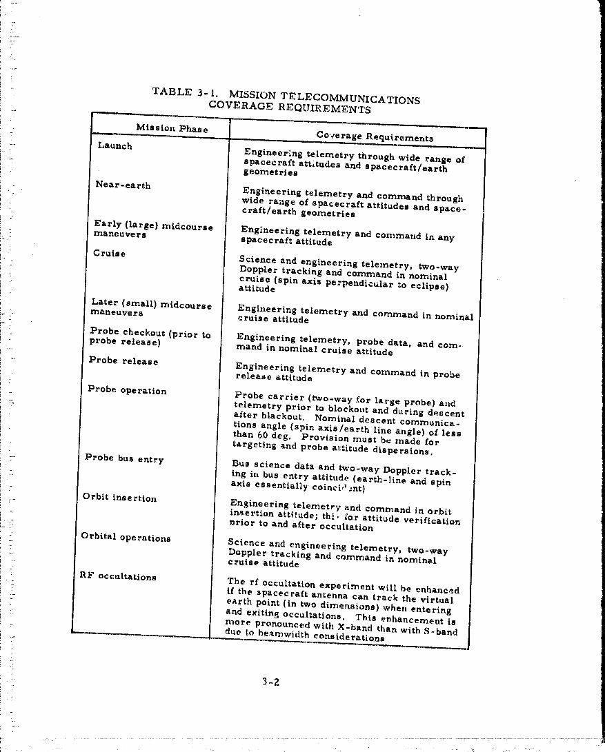
The telecommunications coverage required for the various missionphases is summarized in Table 3-I.
3. Z SYSTEM REQUIREMENTS
This subsection documents the basic Thor/Delta design communicationsystem requirements. Deviations to these requirements caused by changingto the Atlas/Centaur launch vehicle and the change in mission set are dis-cussed in section 6.
A review of Table 3-1 leads to the adoption of the following groundrules for the telecommunications design:
3-1 i
--- 00000001_-r'c_nA|_v.
i-
i "
"4"
.. TABLE 3- I, MISSION TELECOMMUNICATIONSCOVERAGE REQUIREMENTS
: Missiol% Phase Co','erage Requirements"" ___ ._L , L , J, ,t J
.... Launch Engineer'ng telemetry through wide range ofi- spacecraft attitudes and spacecraft/earthi
i-_i: geometries
i Near-earth Engineering telemetry and command throughwide range of spacecraft attitudes and space-
i ' craft/earth geometries
i : Early (large) midcourse Engineering telemetry and command in any
if: !: maneuvers spacecraft attitude! -
Cruise Science and engineering tele,netry, two-way_: Doppler tracking and command in nominal
cruise (spin axis perpendicular to eclipse)i ' attitude
[ :
' Later (small) midcourse Engineering telemetry and command in nominal'_ maneuvers c raise attitudei"
Probe checkout (prior to Engineering telemetry, probe data, and corn-probe release) mand in nominal cruise attitude
Probe release Engineering telemetry and command in proberelease attitude
Probe operation Probe carrier (two-way for large probe) andtelemetry prior to blockout and during descentafter blackout. Nominal descent commanica-
• tions angle (spin axis/earth line angle) of less
i than 60 deg. Provision must be made fori targeting and probe a_:titude dispersions.i :
_' Probe bus entry Bus science data and two-way Doppler track-
! : ing in bus entry attitude (earth-line and spin•-- axis essentially coinci,_..nt)
i -- Orbit insertion Engineering telemetry and command in orbit_ insertion atti!ude; the., [or attitude verification
l_rior to and after occultation
: Orbital operations Science and engineering telemetry, two-way_" Doppler tracking and command in nominal- c raise attitude
RF occultations The rf occultation experiment will be enhancedif the spacecraft antenna can track the virtual
: earth point (in two dimensions) when enteringi :Z and exiting occultations. This enhancement is
more pronounced with X-band than with S-,banddue to beamwidth considerations
.... 3-2
...... oooooo01:TsBi_- .... _ -
! .....
_i i. • _ull mission spacecraft command capability in attitudean_
- • Near-earth telemetry coverage in any attitude (.launch,
near-earth, early TCMs)
.... . • Full mission coverage in nominal cruise attitude
r_.' • Coverage for unique scheduled situations (probe release, probe_, " bus entry, orbit insertion)
., Additional ground rules arising from mission requirements, the low cost
!_.!-" objective and design decisions include the following:
_, • Compatible with DSN configuration specified for the 1975-1980
I_ I period
_ • Maximum use of the Z6 m net. The 64 m net used only for
_,;..... mission critical events.
_._ - • Utilize S-band for all telecommunications. Limit X-band to
_- radio science applicv:tions.
• Maximum commonality between the telecommunications
_:i_ subsystems on each of the vehicles
___' : Good spacecraft operability considerations include:
_-_ --
_i_, • Separate transmit and receive functions as much as possibleL_
!_-._ • Provide circular polarization for all links for operational_:'__ simplicity
_., • Size beamwidths for minimum operational impact
_: " The design philosophy arising from these ground rules is to provide!_i spherical command capability throughout the multiprobe and orbiter missions
I by the use of two switched, omni antennas which together give greater than
L_ i -6 dBi gain over the sphere. Given the existence of the omni antennas for
the receive function, they can be efficiently utilized for the transmit function
_i.... times of nonstandard spacecraft attitude such the launch andduring as phase
_. TCMs. The transmit function during standard or predictable spacecraft_- _ attitudes (cruise, bus entry, and probe and orbital operations) is provided byi_, ,
_ : antennas selected especially for these purposes. The selection of these
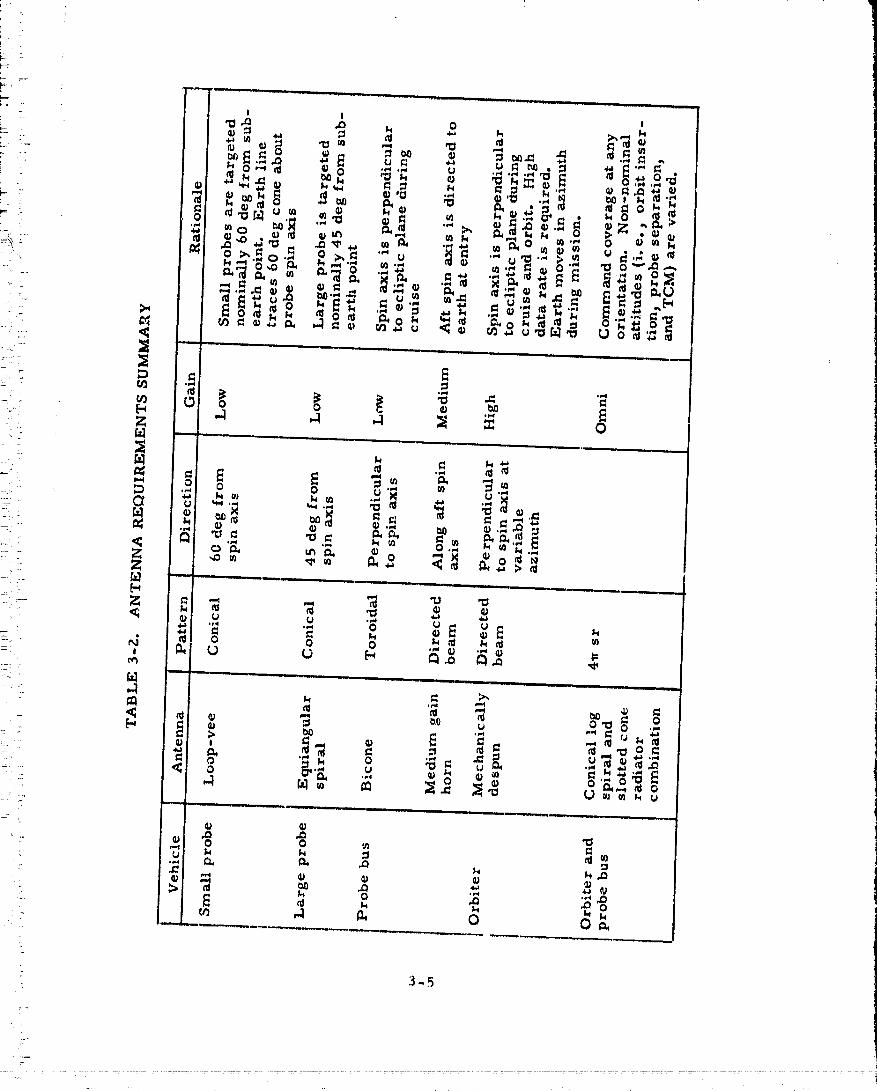
_ . antennas is discussed in the trade study section of this voluJne. Antennai;._ coverage requirements are surnmarized in Table 3-2. Line drawings of the
probe bus and orbiter showing the location of the antennas selected to meet
_ i' these systems coverage requirements are shown as Figures 3-I and 3-.2.
i
?
'"
3-3
: " 00000001-TSB06

NARROWBE/UW OMNI
g
MEDIUM GAIN
BICONE
- 3-4
3-5
-m
..... 00000001-TSB08
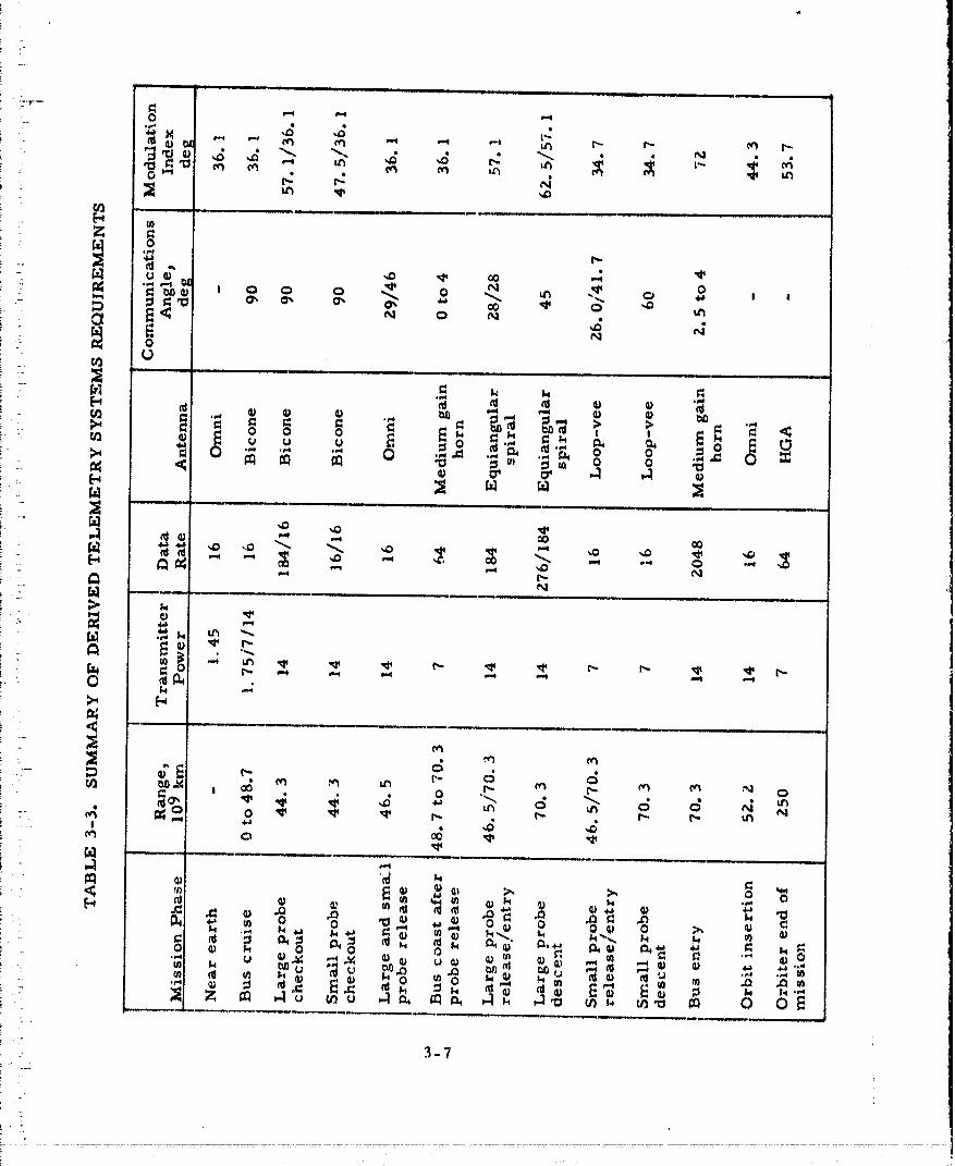
In the launch, near-earth_ and midcourse phases, _he requirementwas telemetry coverage at modest bit rates for spac.ecraD control and moni-toring. During the cruise phase, emphasis was on providing telemetrycoverage for science and engineering without altering the spacecraft attitude.The probe bus had special requirements relating to bus attitude during proberelease and._cience return during bus planetary entry. The orbiter had tostzpport high science return data rates during orbit operations. No communi-cations requirement exist_ d for orbit insertion since this occurs in earthoccultation. However, communications had to be maintained before and afteroccultation for spacecraft operations.
The sizing of the telemetry links followed directly from the sciencecomplement and associated experiment data return requirements given forthis systems design study. The probe data rates resulted from the descentoptimization trades discussed in Volume 3 of this report wherein descent
:: speed (and thus data rate) was varied to achieve weight and/or cost minimiza-:_ tion. The orbiter link was sized by the requirement to telemeter science data
at maximum Earth-Venus range (end of mission). In this case the raw data- return requirement was further modified by the addition of spacecraft data-_ storage so that the required data transmission could be averaged over a signi-! ficant portion of the orbital period to prevent designing to a peak rate of small
duration (periapsis pass). The probe bus link was sized by science datareturn requirements during probe bus entry and by the requirements forspacecraft status data over omnidirectional antennas during the probe releasesequence when the spacecraft is not in its ;:tandard altitude.
The command links utilized the standard DSN PCM/PSK/PM modulation.• he telemetry links were also PCM/PSK/PM and compatible with the DSNmultimission telemetry system. Convolutional encod_.ng was used on the down-links to improve link performance with minimum cost and hardware impact.The link performance calculations are discussed in Volume 3 of this report.From these calculations the system design parameters were derived. Forthe downlinks the required effective radiated power (ERP) can be allocatedbetween antenna gain and transmitted power considering the spacecraft primepower availability and the antenna coverage requirement discussed previously.There is a great deal of interaction between the selected implementation andthe allocation of these resources a_ will be discussed in the followingparagraph.
The design of communication links with existing spare hardware andground station links is an itera'Ave process. The requirements specify theperformance, and then the available hardware and existing ground stationcapabilities are examined to see how this performance can best be met. Insome cases this process r...sults in a modification of performance if the over-i
all requirements can be satisfied with a cheaper or more _asily implementedsolutions. Under these circumstances_ it is not possible to entirely separatethe required performance from specific implementation schemes and thesystem requirements. This can be seen in Table 3-3, which lists the telemetrysystems requir(;me.nts derived from the cor_sid(_rati¢ms discussed in thissection.
:7
?,-(_
00000001-TSB09

3. 3 SUBSYSTEMS REQUIREMENTS
. The telecommunications subsystems requirentents resulting from the- mission _nd systems requiret_aentsdiscussed above and from other systems" and subsystems trades are listed on Tables 3-4 through 3-7. These require-- ments are the basis for the subsystems designs discussed in sections 5 and 6
of this volume.
' TABLE S-4. ORBITER COMMUNICATION SUBSYSTEMSREQUIREMENTS
Antenna Subsystem
_ = • Two switched omnidirectional antennas
!_'!,i- Right hand circular polarization i
i :.... > =6 dBi gain over sphere ITransmit 2295 MHz_ receive 2115 MH_ i
t I3_J
• Mechanically despun high gain parabolic dish antenn,t (MDA)i _ !i pointed normal to spin axis
i"
• Right h_nd circular polarizationDespin azimuth pointing contr ol
"! > 23.5 dBi peak gain_. ' 1 1 deg beamwidth!.-
_ Transmit only, 2295 MHz
RF Subsystem
!i_ • DSN compatible• PCM/PSK./PM uplinks and downlinks
i _ -_ • Three selected levels of power delivered to MDA:38.9/36, O/SO. 0 dBm
! -:
: . • Three selectable levels of power delivered to despun omni:_ 38.7/35.8/'_9.5 dBm
" • Two selectable levels of powsr delivered to spinning omni:36.8/30.8
!
i '..: • Low noise preamplifier (noise figure = 3. 5 dB)
• System noise temperature = 600°K
_. • Two 7/I. 75 W dual mode solid state power amplifiers
• Phase lock receivers
! • Redundant exciters
• T_o-way doppler tracking, receiver/exciter combination used as'_ -. transponder_ 240/221 turnaround ratio
• One.-way doppler tracking with no upiink (auxiliary oscillator)
3-8
: i
7:.
O0000001-TSB11
TABLE 3-5. PROBE BUS COMMUNICATION SUBSYSTEMR EQU IP,EMENTS
Antenna Subsystem
• Two switched omnidirectional antennas
Right hand circular polarization> -6 dBi gain over sphereTransmit 2295 MHz, receive 2115 MHz
• Bicone antenna
Right hand circular polarization> 3 dBi gain over spin plane30 deg beamwidthTransmit only_ Z295 MHz
: • Medium gain horn
Right hand circular polarir.ation
> 18 dBi peak gain along aft spin axis, Z0 deg beamwidthTransmit only, 2295 MHz
RF Subsystem
• DSN compatible
• PCM/PSK/PM uplinks and downlinks
• Three-selectable levels o£ power delivered to bicone:39.7/36.8/30.8 dBm
• Three selectable levels of power delivered to medium gain horn:40.0/37. 1/31. l dBm
• Three s_lectable levels of power delivered to widebeam omni:39.5/36.6/30.6 dBm
• Two selectable levels of I '_wer delivered to narrowbeam omni:36.8/30.8 dBm
• Low noise preamplifier, (noise figure = 3.5 dB)
• System noise temperature = 600°K
• Two 7/1.75 W dual mode solid state power amplifiers• Phase lock receivers
: • Redundant exciters_
• Two-way doppler tracking., receiver/exciter combination used astransponder., 240/221 turnaround ratXo
• One-way doppler tracking with no uplink (auxiliary oscillator)
3-9
O0000001-TSB12
_- 'FABLE 3-6. LARGE PROBE COMMUNICATION SUBEYSTEMSREQUIREMENTS
I
Antenna Subsystem
:: • Equiangular spiral antenna
Right hand circular polari_.ation: Conical pattern.... Peak gain 45 deg from sphl axis
> 3.9 dBi ± 10 deg from peak: 40 deg beamw_dth:: Transmit 2295 MHz_ receive 2115 MHv,
,.-._ RF Subsystem
- • DSN compatible
,: • PCM/PSK/PM downlink; carrier only uplink
i • Power deltvered to antenna >40.4 dBm
i . • Low noise preamplifier (noise fi-gure= 3.5 dB)
'::: . • System noise temperature ---600°K
.-:/ • Tw_ 7 W solid state power amplifiers
: • Phase lock receiver
i-.. • Two-way doppler tracking_ receiver/exciter combination used asa transponder_ Z40/2ZI turnaround ratio
• One-way doppler tracking with no upli,_.k(auxiliary oscillator)i .
i=
i-
} ..
i-- .
_-.
•" 3.,]0
" ...... O0000001-TSBI'
_...... TABLE 3-7. SMALL I_ROBE COMMUNICATION__ .. SIIBSYS'I'r?MS REQUIRI£MEN'YS
. ::. Antenna Subsystem
- • Loop-w¢o anteenai ,'1,':
,._r. Right hand circular polarization:- - Conical pattern!'__ tJeak g_in 60 dog from spin axis-,, : >Z. 4 dBi _ 10 deg from peak
• ' 40 deg bean,widthTransmit only_ Z295 1Mlfz
_.,,-- RF Subsystem
• DSN compatible
: • PCM/PSK/PM downlink
.<. - • Power delivered to antenna > 38. 3 dBm
" , • One 7 W solid state power amplifier
? . • One-way doppler tracking (stable oscillator)
:i
.
:i
2;
, $
'- 3-ii
• 7
O0000001-TSBla
_-: . 4. TRADE STUDIES
_:i:i;7=21:= ....... The communication subsystems have a number of special requirements_, : imposed by the Pioneer Venus mission. The high-g ( - 500 g) and high temp-
!__- eratur_ environment (-'700°C at the antenna) experienced by the probes,-:_ ... coupled with th_ demands of minimum size and weight, required preliminar 7_2_;: experimental investigations The measured performance of a stable oscil-
..:. lator revealed that this was indeed a problem area requiring further_'! investlgation. These investigations also included obtaining antenna test
..... patterns for preliminary antenna designs applicable to the large and small_;_,. probes. Probe thermal desigh tradeoffs also required knowledge of how
,i : severely the components would degrade with increasing temperature so:--,. th_ !imlts could be set on the internal probe temperatures. Measurements-_:: were, therefore, made on the performance of an S-band power amplifier at
_!:_i: elevated temperatures. Performance wi.th temperature of existing DSNcompatible transponders was also investigated
:. Other tradeoffs included a comparison between electronically and.-2 ]:
__ mechanically despun high gain antennas, an industry survey of available_;.,_ microminiature transponders, and a tradeoff between solid state powerJ=- amplifiers and TWT amplifiers.
_:_ The final selection of preferred components meeting the communi-_:_'- cations subsystems requirements has been made on the basis of several
criteria, derived principally from the overall mission requirement of low_Z)I::=. cost. They are:
5_ _.... 1) Low technical risk, known design== i.: _
:._.,:-- 2) Off-the-shelf availability
_:: : 3} Commonality between probe bus, orbiter', large probe,• :: and small probe
,::. ,- 4) Low weight and volume (particularly for the Thor/Delta- : design)
5) High reliability
4_1
• ...... "" 00000001-TSC01

,(
i i_
:- [['ABLE 4-I. ANTENNA SUBSYSTEM TRADE STUDIES
Principle Reasons /Trade Study Selected Approach Experimental Results
Omni-directional Combination of conical Gain/coverage. weight,i antennas for probe log spiral and slotted availabilityof design[ ,
bus and orbiter cone radiator
Orbiter high gain Mechanically despun Proven space hardwareantenna antenna-parabolic design, low weight, and
reflector with focal complexity: point feed
Probe bus medium Conical horn Rugged, simple, design; gain antenna scaled from existing hard-
ware, easily mountable
:. Probe bus azi- Bicone Scaled from existing hard-muthal omnidi- ware. meets gain require-rectional antenna merits with minimum
t- : complexity! "i
i_ Probe antennas Equiangular spiral for Equiangular spiral chosen! : large probe, and loop- for gain/coverage. Loop- 'i i vee for small probe vee because of its small• size. Former satisfiesall
_- requirements but loop-veei i" had low gain because of', : small, curved ground plane
e
:i
r,
(.
:-
L
._
00000001-TSC02
L
r"
......_' Tables 4-1 and 4-2 summarize the principal results of the various- trade studies. Although the studies were originally performed to be
directly applicable to the Thor/Delta spacecraft design with great emphasis_-. on weight reduction, most of the results are also applicable to the Atlas/:_ Centaur design. Section 5, the Thor/Delta baseline:design, is directly,,_ ,. based on the results of these studies. Section 6, which represents the
Atlas/Centaur baseline, modifies some of the conclusions reached herein.- due to the relaxed weight constraint which allows increased emphasis on
_ low cost approacims. Also, coincident with the change of launch vehicle,: there was a change of mission set and baseline science complement which
! altered the subsystems requirements somewhat.k,
2-
,. c" 4. 1 PROBE ANTENNAS
'_ The gain/coverage and other electrical requirements associated with: " :: the probe antennas are listed in Table 4-3. The gain/coverage values are:. design goals. The dimensions are proportioned from the pressure vessel
'_=" sizes and the approximate sp_.ceavailable for the antennas.
The conical pattern for the probes can be achieved with any one ofi the antennas listed in Table 4-4. Size weight, polarization and pattern
_- constraints limit the number of candidates worthy of consideration to just a_ r" few types. For example, the pattern has to have uniform signal level in- :- the $ (spin) direction, and a conical pattern with a null at B = 0 in the 8_-_: (elevation)plane. Main lobe radiation patterns of some of the more interest-
' ing candidate antennas are compared in Figure 4-1. The pattern of an axial' :: mode helix radiator is included for comparison to show the relative differ°
' ence in gain and the pattern fall-off as a function of coverage angle. The' radiation patterns of these candidate antennas were obtained from the lit-. , erature. These data were used as an indication of the approximate and
: :. relative performance achievable with the candidate antennas.
.! .... The equiangular spiral is selected as a model antenna because iti :- best meets the overall design goals listed in Table 4-3. Two important: " advantages of the equianguler spiral antenna are that it is smaller than
,,.. the annular slot antenna and it .easi].y provides the needed beamwidth.
• The loop-vee antenna is chosen as a possible antenna for the small': probe, because it is small. The peak gaiP is not so high as some others, but
it is nea.rly constant over a wide angle.
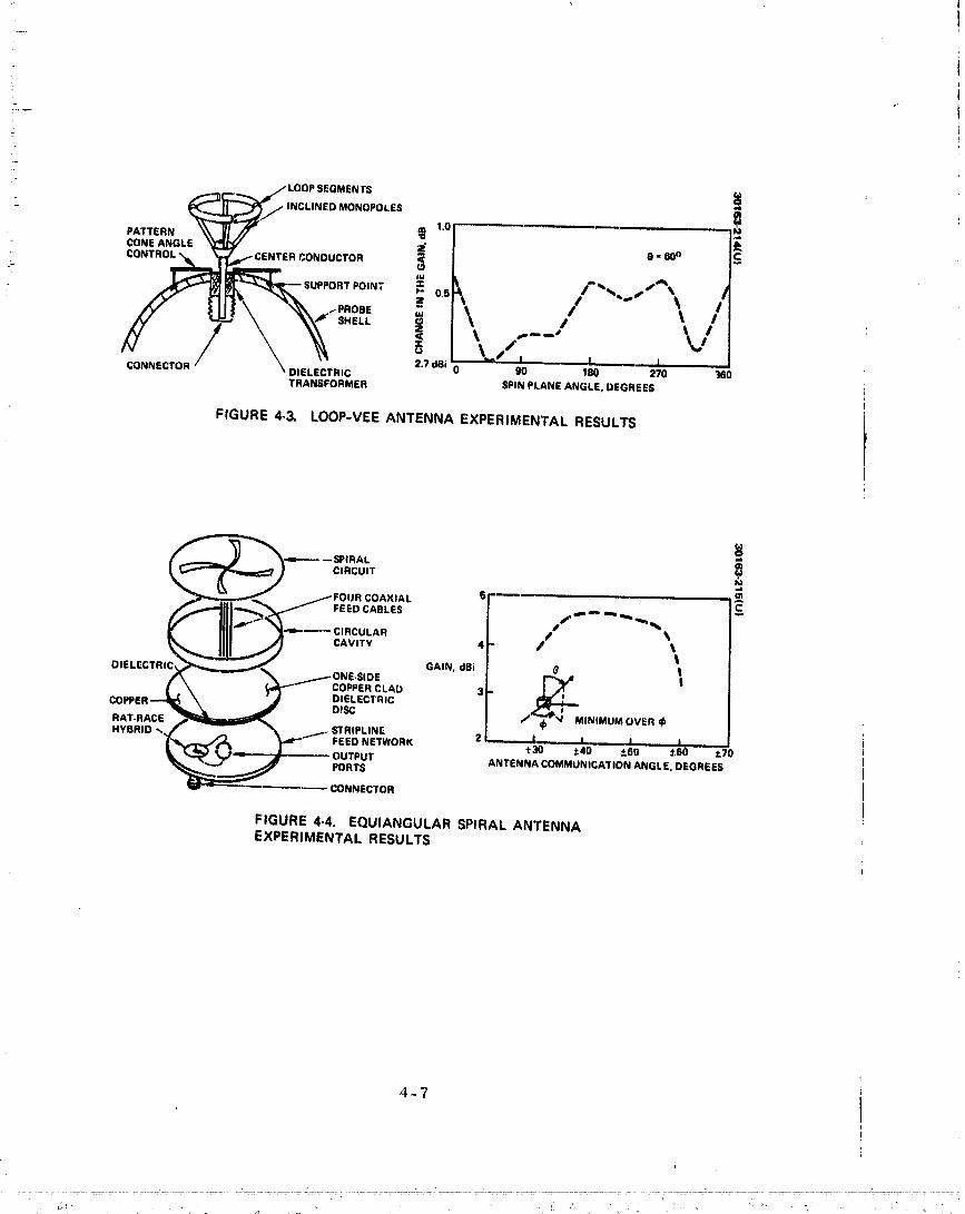
- :i Experimental models of these antennas, shown in Figure 4-Z, were:-- built and tested. Construction details of the loop-vee a.ntenr,aa,..ditsgain
in the spin plane are shown in Figure 4-3. Similar information is givenf r the equiangular spiral in Figure 4-4. Figure 4-5 illustrates the
:- symmetry of the antenna gain with spin angle. Typical antenna radiation"_ " patterns are shown in Figures 4-6 and 4-7. Further information concerning
: this experimental trade study (:an be found in tlughes Aircraft CompanyTIC 41-16/73/051, "Development Study of Planetary Probe Antennas"
:_ included i.n Volume 15 of this report.
4 _.3
, , 00000001-TSC03
i
TABLE 4-Z. RADIO FREQUENCY SUBSYSTEM TRADE STUDIES
Principle Reasons /Triode Study Selected Approach Experimental Results
Microminiature Viking lander trans- Low cost, weight and size.transponder ponder (Philco-Ford) DSN compatible
Power amplifier 7 W solid state module Commonality between probesand probe bus and orbiter.Smaller size and weightthan TWTA
Stable oscillator Test HP 10543 oscilla- HP oscillator met 1:109_tot. Study alternate stabilityexcept for 5:10'designs by APL and frequency shiftafter high gFEI test. Alternate design (FEI}
smaller, less weight
Communication Mechanical switches. Low loss, high isolation,...... subsystem passive Filters separate from probe packaging
components diplexer
High temperature Test power amplifier Power output degrades toelectronics 5.5 watts at 93°C
High g electronics 'restHP stable oscil- Point to point and printedlator and other compo- circuit construction success-nents with representative fully meet greater than 500gconstruction
4 -4
- ^^.... TSCO_.... " -_-......":: .... ...... ..... UOOuOu01-...... i

7̧
7--
,7
TABLE 4-3. PROBE ANTENNA DESIGN GOALS
i'
- Item Large Probe Small Probe
Frequency, GHz 2.115±0.005;2, 295 2.295 ±0,005_. ± 0. 005
Antenna pattern Conical Conical
i Polarization Right-hand circular Right-hand circular
i /i Coverage angle (elevation) 45 ± I0 60 ± 10,_ deg
:r
L .....
ir :"
_"/L
S _ ....................
p. , _.HELIX /ANN.r: ULA.SLOTR*NG
6 ! ,_ _ "_ CON=CALSPIRAL
:.E lat3 _ /(_, MOD=)r-.. > %,
-14 '= ar • "__ _WFOUR-ARM _ • •PLANAR SPI RAL _ _ I;(A MODE _ Jr
2
" '_ LOOPVi[E •
0 10 20 30 40 80 60 70 80 90
::_ PATTERN ANGLE, 8, DEGREES
-, :i FIGURE4.1. PROBEANTENNACOVERAGEPATTERN!-
!-
_ ! _
; FIGURE4-2, EOUIANGULARSPIRALAND LOOP-VEE; ANTENNAS(PHOTO4R29622)
4-6
II I I , , ............
00000001-TSC06
t
_ _/,-1"-'_ ,j,,,,,LOOPSEGMENTS
! _NEANGLE___ CONDUCTOR_ I e'"° /S
I _.,/, • " I,D,E.EC,.,C ,.,,B,o ,o ,_o ,',o _loTRANSFORMER S.iN,',.ANEANGLE,.EG.EES
FIGURE 4-3. LOOP-VEE ANTENNA EXPERIMENTAL RESULTS
01
O1
t
COPPEROI ELECTRIC/,_,____..,_ _. m- _ONE DISC SIDE GAIN, dBi _M t
/ \ _ CO_ERCLAD tL .,, \ ' • DIELECTRIC
--_.J_. J / ,._MU.o,,E.RAT.RACEHYBRID _. f _- _ _..i.,,, STRIPLINE
--_ _'r FEED NETWORK 2 l, ,A I J_3o ,.4o ±_o _6o _?o• r_ _,,,_.,,,,m,-----_..,_ OUTPUT ANTENNA COMMUNICATION ANGLE. DEGREES
_ F_DRTS_-- CONNECTOR
FIGURE 4-4. EQUIANGULAR SPIRAL ANTENNAEXPERIMENTAL RESULTS
4-'7 I
nnnnnnn I _T.qC.fl7U_Jk/k/_,./vv| |_'_'"--

W̧
77} L.
_, _= 90 DEGREES
..... - |1 / GAIN _' ntl,m t _JlOdB
'-;';,_." _= leO,--__EVEL dB "-_]X-_O.0 DEGR
, 13o-,..<.---]- .>./3,0i _= 270 DEGREESi
_' _ FIGURE 4.5, SPIRAL ANTENNA GAIN VERSUS
i :.: AZIMUTH ANGLE, 0--- 45 DEGREESi
i-
. . , . .. • ..... , .... _
............... .... 00000001 TSCCi

00000001-TSC09
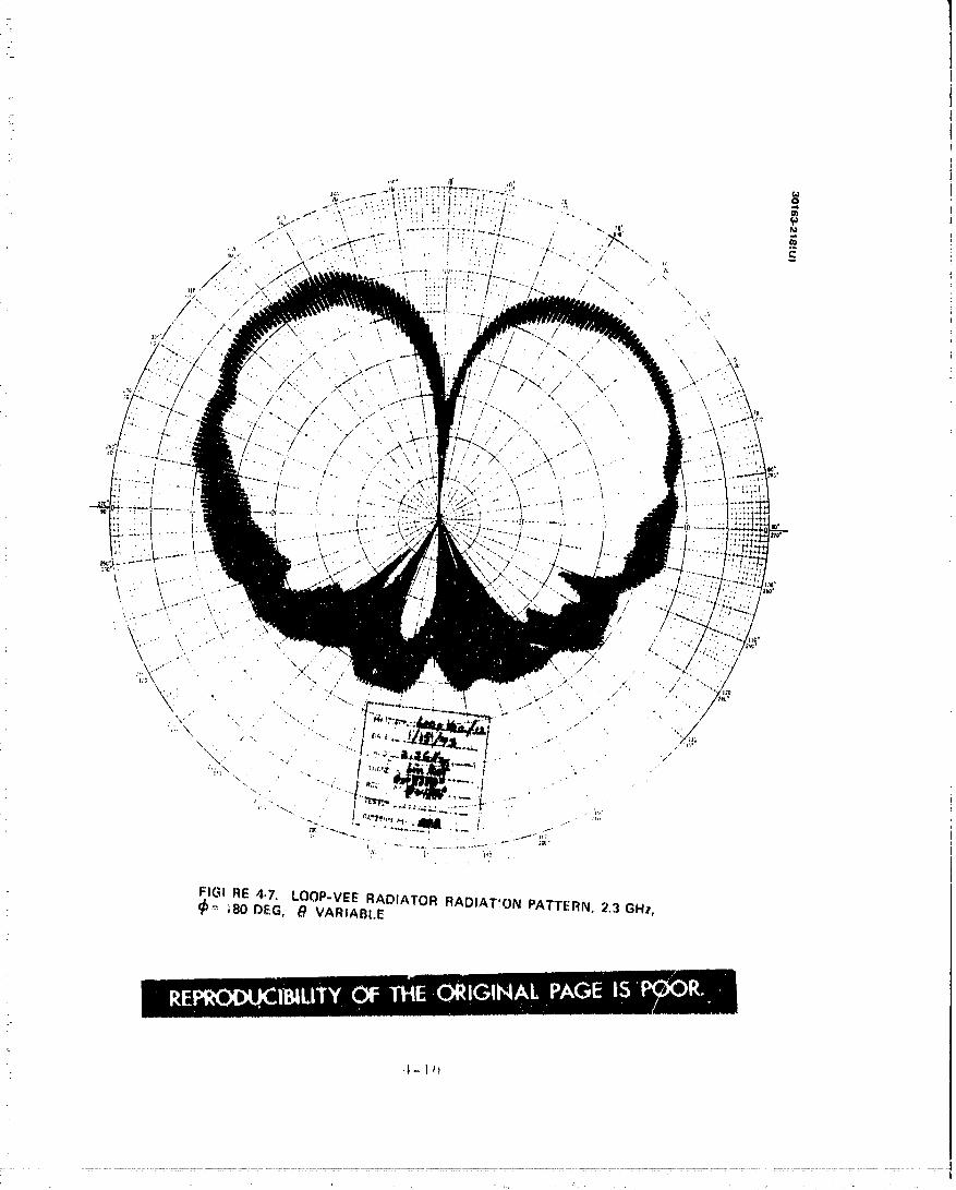
FIG! RE 4-7. LOOP-VEE RADIATOR RADIATION PATTERN, 2.3 GHz,_ ;80 DEG, _9 VARIABI.E
O0000001-TS(

i
r
/
! : 4. 2 PROBE BUS ANTENNAS
_] :: The subsystem must iulfill three different antenna coverage require-..... ments on the probe bus. A medium gain antenna with gain directed along
:,- the aft spin axis is required during bus entry, an antenna with a to, oidalbeam about the spin axis is required during cruise, and essentially omni-
! .... directional coverage is required for command reception and telemetrywhile the bus i_ in nonstandard attitudes.
Medium Gain Antenna Selection
Prime candidates for the medium gain antenna are end-fire radiators. and horns. The end-fire radiators such as the helL_, yagi, and disc on rodi-: antennas must be mounted away from the spacecraft structure to avoid inter-_-__. ference. These antennas also have to be at least five wavelengths long and
:!i thus are structurally undesirable. An array of end-fire radiators would bei '
_- _" more suitable, but the array stillhas the problem of mounting so as to,, avoid interference from the spacecraft structure. Since only the aperture
i-_;.S of a horn must be unobstructed, this antenna can be located within thespacecraft structure with no interference. The horn antenna is also much
[ ....
_--_• simpler than the end-fire radiator, and the design parameters can bei:!" scaledfrom existinghardware.
i= ..... Table 4-5 summarizes the candidate medium-gain antennas. A' single conical horn is selected as the most advantageous when all factors_,. are considered.
,m }.
•:: " TABLE 4-5. CANDIDATE MEDIUM GAIN ANTENNAS
L .
Antenna Type A dvantage s Dis advantage s
i End-f_re radiator Design available Mounting to avoid interferencei--_ ; with structure [s difficult.i .... Length of antenna is structural
i " problem.i
i Array of radiators Shorter than single Compl.ex, new design, mounting, :. end-fire radiator to avoid structu.ralinterference; is difficult.i "
__/:-: Conical b.orn No st'.rucb_ralinter- --.... fe rence problem.
Can be scaled from
:. existing hardware|
'i
7o
" 4-11
............. J..._
O0000001-TSCl 1

!, ]
!i
4-17.
00000001-TSC12
i'
Toroidal Beam Antenna Selection
Candidate antennas to provide omnidirectional coverage in the spin- plane during probe bus transit awe a bicone, conical log spiral, and an
array of radiators. The third candidate is the m_Jst complex and expensive.It is related to the electronically despun antenna in design concept. 'the
, pattern in the spin plane will have a gain ripple, The bicone arid conical:: log spiral are simpler antennas and caa be scaled from existing hardware.
The bicone consists of a circular array of slots on a circular feed"" waveguide radiating into a circularly symme.tric flared region. Circular
polarization can he achieved either by using crossed slots or single slots: at 45 deg inclination.
- The conicalspiralis smaller indiameter than the bicone antenna,but longer. For a base diameter of I0.6 cm, the heightofthe conical
: spiral is 40 cm. To provide an azimuthal omni pattern, a four arm sp,_.ralhas to be excited in the first order difference mode and designed with afastspiralgrowth rate as shown inFigure 4-8. The cone angle is con-
, trolled by the spiral growth rate. If the spiral antenna had more gain: when operated in the difference mode, it could be used as two antennas in
: one, by exciti_:_gthe spiral in the sum and difference mode and using it in,_ : place of the bicone and *.he back-omni.
i _ Table 4-6 summarizes theadvantages and disadvantagesof the !i _ various antennas which give rise to toroidal beam patterns. The antenna ',i gain requirement in ,:he probe bus is best met with the bicone antenna since '_
it is relatively low cost and its design can be scaled from existing space: hardware.
i
! i
i.
; : TABLE 4-6° CANDIDATE TOROIDAL BEAM ANTENNAS
Type of Antenna Advantages and Disadvantages
_: Bicone S caled frorn existing ha rdwa re
i Conical log spiral. Low gain, long, slender, small base diameter,g scaled from existing hardware
Multiple radiators Complex, heavy, costly design, ripple ini spin plane
i_
i :
i
. " 4-13f
i
t
' 00000001-TSC13

!1
it-}.
i,I 1
.L _ "CI' '#_,;IJC IOR
_lw .
_ " CONICAL I.OG TYPICAL (_.PLANE RADIATION;t- " SPIRAL RADIATOR PATTERN
FIGURE4.9. CONICAL LOG SPIRAL ANTENNAi
i-: Li-- "
i "
i l .:. 220[ 7.5 _
=.. 2oo_ ,180,-. ',, 10 i 0 _ -_
L 5\\ ,.,oo_ \_ \\\\ :_,6oii
,,oi "_'d Ilo• 20[- ,,.,!" ¢ n_
A.= 15,O in.)
. t.,,...:__._do_, I°a-_--a'o-_6o7o
7
SPIRAL ANGLE )"_
FIGURE 4-10. CONICAL LOG SPIRAL HALF FIGURE 4-tl. 3L,OTTED CONE RADIATORPOWER BEAMWIDTH AND APPROXIM_,TE (SURVEYOR TYPE)
" DIRECTIVITY
4-14
I
O0000001-TSC14

3' S_pherical Coverage Antenna Selection
.... To provide spherical coverage about the spacecraft, at least two_i - radiators, each giving approximately hemispherical coverage, are needed.
Several antennas are app.£icableincluding the conical log spiral, slotted.- cone, planar spiral and curved turnstile. The first two can provide better
i? than hemispherical coverage whereas the latter two provide coverage over.... only one-half to three-fourths o£ a hemisphere..
_. The conical log spiral (Figure 4-9) is a broadband radiator that can
,! be designed for wide angle coverage. Much design information has beengenerated over the years and design costs can be reduced by using these
_ ava'lable data. Figure 4-10 shows the wide range of gain/coverage_. achievable. The spiral angle, _, is related to the spiral wrap factor. A _
large spiral angle means a tightlywound spiral. The angle 6oiS the spiralhalf-angle. As e° approaches zero, the conical log spiral becomes a log
-_ : helix.
The slotted cone radiator, Figure 4-11, consists of a crossed-dipole_' element radiating through a slotted cone. The feed of the crossed-dipole_i is a simple split-tubebalun. Circular polarization is achieved by exciting- _ the orthogonal elements of the dipole in phase quadrature and with equal__ ::. amplitude. The latter is accomplished by keeping the length-versus-=_ diameter ratios of the two dipole arms equal. The proper phasing is
achieved by adjusting the length of the two dipole arms to be unequal until...... a 90-deg phase difference exists between the impedances of the arms.
- Measured patterns (Figures 4-12 and 4-13) show the wide angle coverage_ achievable.
7'
-j, The planar spiral is the special case of the conical spiral with
8 o -C_0 deg. The spiral growth can be defined either as geometric change_ r = e _or as an arithmetic change, r = C¢. The dimension r is the radius'" vector from the center of the spiral to a point on the spiral _bdeg from _b=0.
The other variable, C, relates to the spiral growth rate. The geometrically-_'_ growing spiral is known as the equiangular spiral. The arithmetic spiral is_T
__ also called the Archimedean spiral. Typk:ally, coverage is over not morethan lZ0 deg with either type of planar spiral. The more tightly wound
= i- Archimedean spiral is preferred when clean, circularly symmetric, .... patterns with good axial ratio are important as they are here. However, the
..... gain coverage is on the order of one to two dB lower.
The curved turnstile radiator has itsdipole arms bent down towardsthe ground plane so that the beam broadens. To obtain acceptable circularpolarization, a two-line feed is energized through a 90-deg quadrature
_ - hybrid. The dipole arms can be flatleaves curved down. The modifiedi_ turnstile radiator has gain/co_,erage characteristics very similar to the
planar spiral antenna.
4-15J, ,
......... • O0000001-TSD01
9o_meRs ._
_yX.- _ \ / " "\ RELATIVE POWEE LEVEL dB
' a5 Is180 -""" _"....." ............. ' ..... *" 0/
: ._. \ ,/ \ S#\ / _ j
/ . \
\
I/1 _ i x
- 270
_. FIGURE 4-12. ELEVATION (8 PLANE) PATTERN, SLOTTED CONEANTENNA, 2.295 GHz
)0 DE_,EES oI
I \ __ RELATIVE POWEk LEVEL dBi
t
: " _ 25 15, 58o - -I ; : - -----+---4-_4- o. ._ _ I -.
/
.- \ / "_. _- \ ",/
I I i- 2 r0
_. FIGUHE 4-13. AZIMUTH (• OR SPIN PLANE) PATTERN, SI._TTED.- CONE ANTENNA, 2.295 GHz
4- 16
::-:" 00000001-TSDO:,
! -
i -
7
Table 4-7 summarizes the characteristics of the candidate omni-
. coverage radiators. Considering size, weight, design availability,and- gain/coverage performance., an antenna subassembly consisting of a_- slotted cone radiator and a conical log spiral is preferred. The slotted• cone radiator provides coverage over 220 deg, and the conical log spiral: fills in the remainder of the sphere. This antenna combination is appli-t cable to the orbiter as well as the probe bus.
4.3 ORBITER ANTENNAS
" The orbiter requires a high-gain antenna to support science telemetryi _: during the orbital phase of the mission and spherical antenna coverage for
command reception and for telemetry transmission while the orbiter is ini , nonstandard altitudes. The spherical coverage antenna requirement trade
i is identicalto that presented in subsection 4.Z for the probe bus. The} antennas (slottedcone and conical log spiral) selected to provide omni-- directional coverage are the same for both bus and orbiter.
i -
:- The choice and design of the high-gain antenna for the orbiter space-. craft is influenced by the spacecraft and communication system design sel-
ections. For the axis normal to the of thespin plane ecliptic, a despuni • antenna assembly or an azimuthal omnidirectional (toroidal)antenna pattern_: :- are required. The latter approach is very unfavorable because of the muchi= lower antenna gain and the concomitant requirement of much higher tzans-i :i mitter power to support the orbiter data rates. Therefore, this sectioni- focuses on the following three candidate despun antenna systems:i_ I) electronically despun antennas, 2) mechanically despun antennas,i ': and 3) mechanically despun reflectors.J! 7"
i i:-_. TABLE 4-7. OMNIDIRECTIONAL/SPHERICAL COVERAGE ANTENNAS
= .
_ _, Conical log spiral Design-variable coverage, 50 to ZZ0 deg half-power beamwidth. Broad frequency band of
: operation. Hardware can be scaled frorn existing
_-: hardware.
i Slotted cone Lightweight, greater than hemispherical coverage,radiator hardwa re available,
i-: Planar spiral Less than hemispherical coverage, low profile,! hardware can bc scaled from existing hardware.
: Curved turnstile Less than hen,ispherical coverage, new design
i
_ .
_: .
4-17
i - 00000001-TSD03

7
/
i_ ElectronicallD_un Antenna (EDA)
The electronically despun antenna system has as its functional unitsthe transmit assembly, the antenna proper, and the beam steering/interfaceassembly. The transmit assembly may be a central signal source feeding
-- into a power distributionand control network or itmay be a network of dfs--_: tributed signal amplifiers. The antenna proper consists of the radiators,
' groundplane, and associated structures. The beam steering interface:- assembly includes such items &_ cabling and the power dividing and
switching networks.
For an EDA to be applicable and competitive with an MDA, the EDAshould have low ripple, continuous signal transmission capability, the
_- required gain at the specified coverage angle, low antenna system losses,and low prime power requirement. The criticalassembly of an EDA is theelectronic and control circuitry to despin the antrnna beam. Much of the
_ weight and loss can be due to the method and imph. _.ntationof the despinassemb ly.
:__ The various EDA approaches differ in the following ways:
_, .... 1) Type of array element
_:: 2) Type of rf power sourcei"
-=_. 3) Type of electronic beam despinning
The radiating element for a circularly polarized EDA is chosen on the_ basis of radiation efficiency, gain, axial ratio over the half-power beamwidth
angle, weight, and size. Table 4-8 listsseveral candidate radiators for an_. EDA. The preferred radiators are those that can easily be fed by coax and_:: have a low form factor. The crossed dipole is a prlme candidate. The two:: cavity backed slot radiators are also suitable elements, especially when the•_, EDA is to be integrated with the solar array. A helix is applicable when:- the space is available between the EDA ground plane cylinder and the inside
wall of the shroud.
o
_. The beam despin network may be one of several designs. Oneapproach uses phase controlled hybrid network_ to feed the rf to a sector
...... on the cylindrical array. A second approach uses rf switches to feed the_.!i signal to only a fraction of the totalnumber of elements at a given time._ In a third approach, final distributed rf amplifiers at the e._.ementlevel in/ the array are dc controlled to vary the rf output at each radiator.
_- In a practical application of the phase controlled hybrid concept_i,_ the phase variation is digitallycontrolled, the ramp portion of the current
" waveforms being approximated in a number of steps. A tradeoff exists"_=- between control complexity and rf ripple. The rf switch control technique:._ is considered least desirable, since it requires the use of a highly reliable,
4_I_
............................ TSDC......... 00000001-

: TABLE 4-8. RADIATION ELEMENTS FOR AN EDA: IN ORDER OF PREFERENCE
Type Design Remarks
Crossed _.,/ Can be integrated with solar array, butdipole ,,d_'._. some shadowing on the solar array.
-if\ Design can be based on Surveyor slottedcone dipoles
Slots -- /_,:._'_'I Can be integrated with a solar array.
i ! J , _,
Helix or Long, does not gitflush with groundplane,other end- _ ":'"_, _,_ does require only part of area available.fire _'_-.l._ ....-_._"radiator
Square or " '" ?,.,h// Best with a waveguide feed network,circular I--__ _ mounts flush, requires fullavailableareawaveg_tide •
Cavity- Heavy, requires full available area, low
backed _ gainspiral . _
Orthogonal / /// Can be integrated with a solar array,
slots loop i!i...._lv/ mounts flush, designed hardwareexcited ill !i/ available
t"-:':L_:'J/
lightweight switch which is not readily available. Using distributed rfamplifiers in the EDA allows amplitucte control at each radiator to despinthe radiated beam. Recent advances in technology make this approachfeasible. The important advantage is the minimization of rf losses in thepower distributionand phasing networks. A phase shifter is required ateach final.amplifier to vary the phase to the appropriate value as a functionof the relative position of the radiating array sector.
A particular EDA design based on an existing design of an L/S-bandEDA which had been developed on company funds for Metsat/SMS was usedas a representative EDA. Alternatives were also considered during the
4-19
........... 00000001-TSD05
-- .'
ZL:
....ii_ F'rELD 0_'V'rEW _.
- \
',.... ELECTnONICALLY DESPUN ANTENNA - LAYOUT OF THE 32 STACKS. OF _ADIATORS, EIGHT STACKS RADIATING AT ONE TIME
7_ 'i }'Ob'I_-TtB, OW 1. 9 25 2 10 18 26 8_],6_2_. 32' SWZTCHES
2' .__zm.P_ _ ........ .._
• PHASE SttlFEE_" ................
': PREAMPLIFIE"R I IlCP,UT FROM ,THE /iF lIVE
FIGUSE 4-'_4. ELECTRONICALLY DESPUN ANTENNA SWITCH/PHASE NETWORK
! 4-20i
7"
00000001-TSD06

_ - systems study. In particular, a distributed rf a_iplifierscheme based on a. Texas Instruments study performed for Ames Research Center" was examined
: during a.systems trade study of high-gain antenna candidates The results ofi' , :
_. - this trade study are given in Volumes 3 and 4 of this report.
The candidate company funded design is illustrated in Figures 4-14.°,
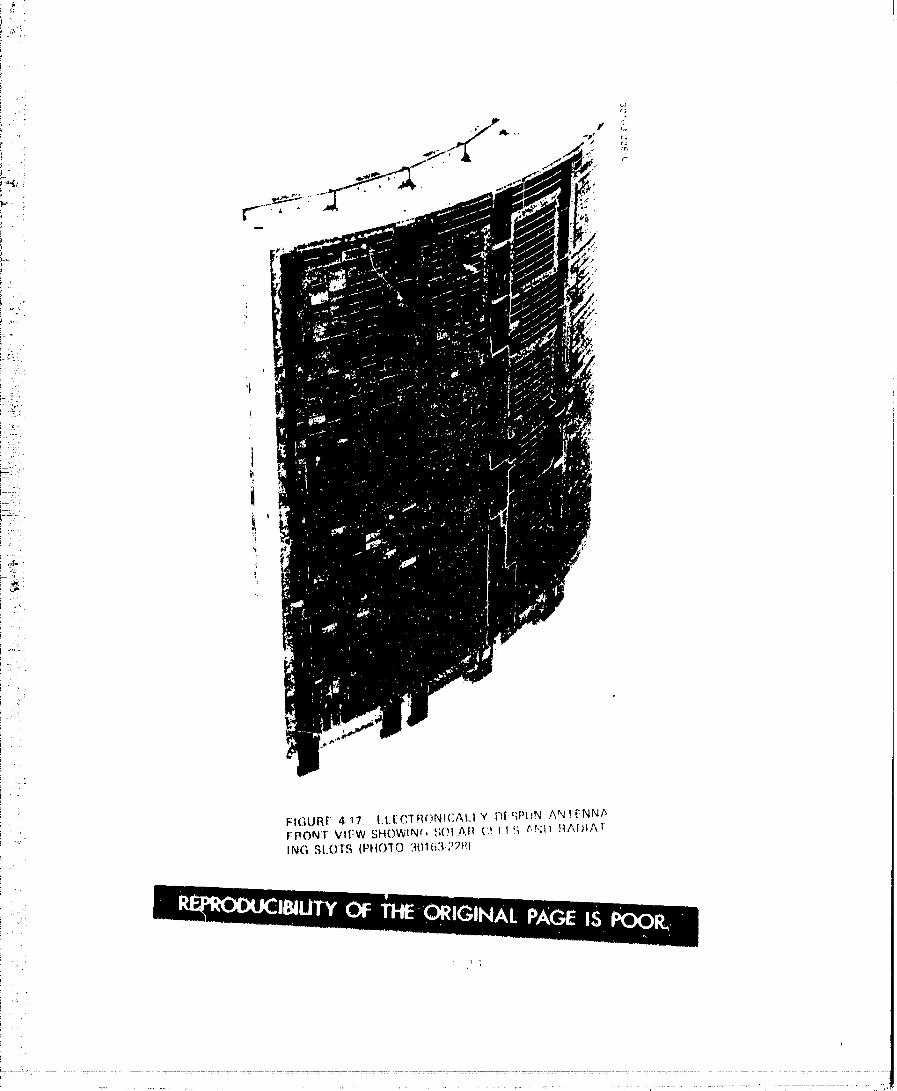
, _ through 4-17. The aperture is a ring of 32 stacks of 5 radiators each. Each,,,,. radiator consists of four slots backed by a loop-excited cavity as shown in
;: ; the cutaway view of Figure 4-15. The crossed loops are excited through .....
_- 90-deg, 3 dB hybrids in order to obtain two equal fieldcomponents in phase_. quadrature_ As seen from Figure 4-17, the slot radiators are interlaced}_ _! with the solar array.
m_ The diameter of the EDA is sized for a 10-deg beamwidth in the.::i. plane of spin. The height of the cylindrical antenna determines the ele-' vation beamwidth (along the spin axis) Of the 3Z stacks of radiators g
_='• are energized at any given time resulting in a net gain of 22.5 dB.
_! ° A switching/phasing network (Figure 4-14) provides for synchronousi-t" :/ rotation of a well defined directional antenna beam. There are eight single-_": pole, four throw switches. Eight phase shifters are required to control thei _.! phase of each energized stack of cavity backed slots. Since the phase
shifters add several dB of loss itis desirable to include transistorF> 7:-
_. amplifiers in the network to reduce the primary rf source power leveli_:._ and establish a better dc to rf conversion ratio.
- Table 4-9 summarizes characteristics of this EDA. The weight...... assumes special construction techniques such as foam structure with
i , 0. 015 cm (0. 006 in) aluminum foil facing.[ - '
: Mgchanical.ly Despun Antenna (MD.A!A'r____ -!2_i
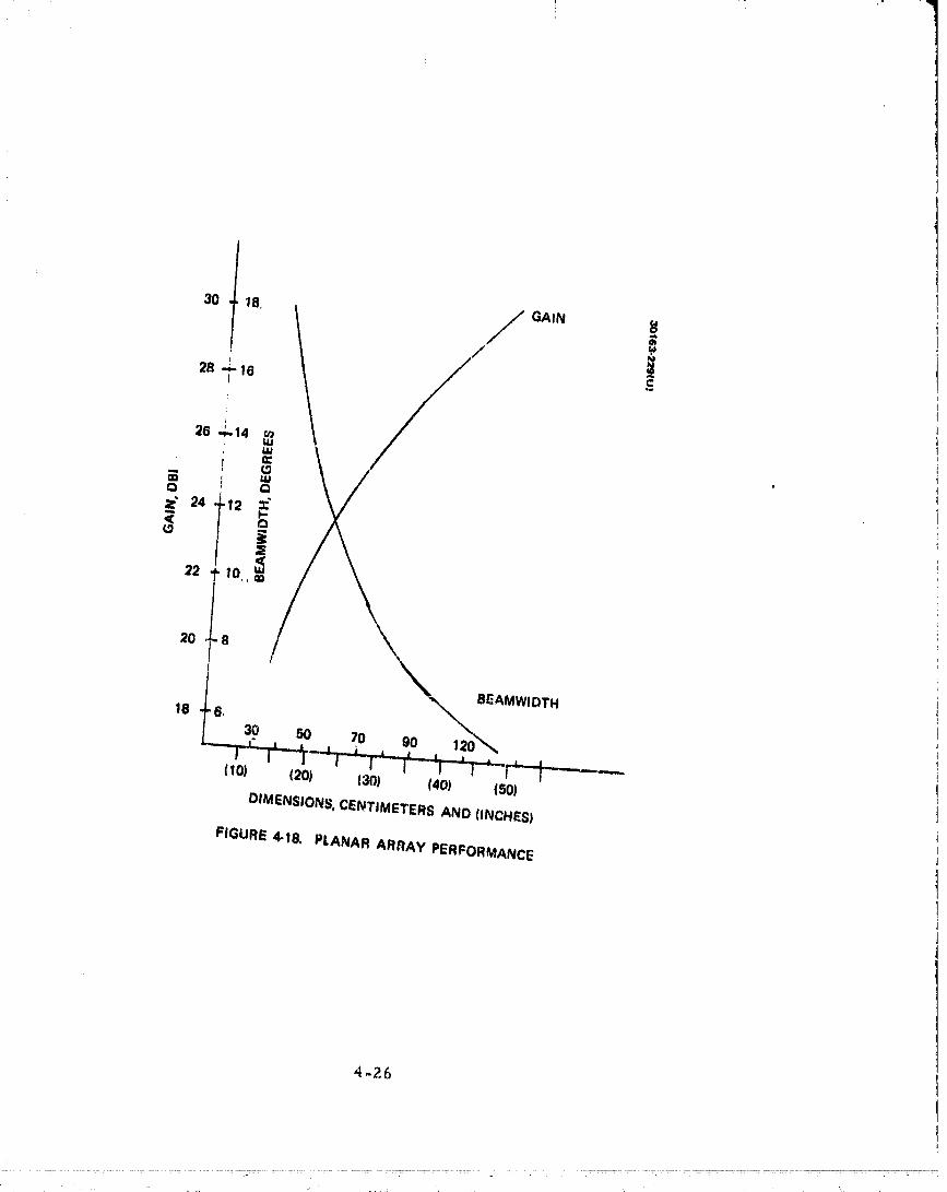
To obtain an II-deg beamwidth and a net gain (afterantenna losses)of 23.5 dB, the mechanically despun array dimensions must be on the order
of six wavelengths. Figure 4-18 plots the planar array performance as ai!__ i_ function of its size. A mechanically despun array may be slightlysmaller
i , than a reflector because greater control over the aperture illuminationexists, 'and therefore more efficient use of the aperture can be made.7
However, this is obtained at the expense of greater complexity.
i _ i. A mechanically despun array may consist of an array of radiatorsi- such as helices or dipoles or the array may be a flatplate slotarray. Thei design of the array of radiators requires the selection of the type of radiat-! ing element and the feed network. Table 4- 10 lists radiating elements.
: R.D. Meeks, "An Electronically Phased Modular Array Antenna forZ Pioneer Venus Communications", NASA/Ames Report U 1-991840-F,
': 22 November [972.
' i°
[ .. ,
q 4-2 t
{ :7} :
[
'.... : ....... ".... 00 00 SD07" 000 l-T----

COAXIAL
. LINES ° 4 OF 32
PACtSWITCHING AND
FHAS INO N_TWORK
z
FIGURE 4-15. S-.BAND ELECTRONICALLY DESPUN ANTENNA CUTAWAY VIEW
00000001-TSD08
i_ _
" _' " 102
L__' '_ 1-- ..- (32.0) , " _
.,.-2:0 ....
;2
;.": 60L
i'
' ;i "' LI
1
_,• \ j
_=:_. DIMENSIONS IN.... CENTIMETERS AND |INCHES)
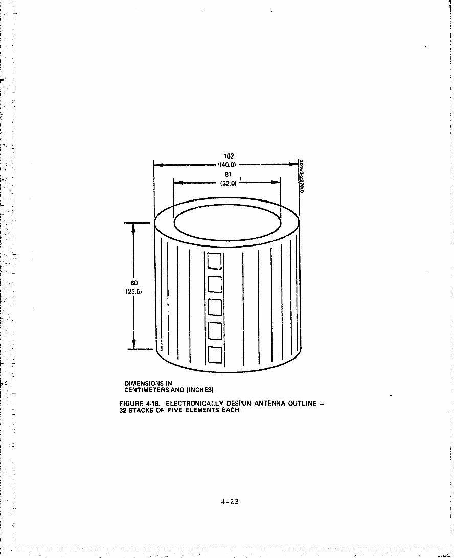
: FIGURE 4"16. ELECTRONICALLY DESPUN ANTENNA OUTLINE -_ 32 STACKS OF FIVE ELEMENTS EACH
! •
:: 4-23
i
00000001 -TSD09

! • !
_Lr"' '
r ": "
. ! TABLE 4-9. HIGtt GAIN ELECTRONICALLY DESPUN ANTENNA (EDA): PERFORMANCE PARAMETERSi
! : Size (cylinder) 1.04 m (40 in. ) diameter, 60 cm-: .: (23 in. ) high
"i
'-: Polarization Circular; axial ratio, 3 dB
!2_ Peak' gain 25.5 dBi
i= : Circuit losses (hybrids/cable) -I. 0 dB
: Switch loss -0° 5 dB
ili Aperture efficiency loss (7¢ l_ercent) -I.5 dBi
_:i:: Total losses -3.0 dB
! i
_: Net gain 2L 5 dBi= .
r=_:- Beamwie_th (spin/plane/normal I0 by I2 deg..... to spin plane)
Massr _
EDA assembly
: Structure (includes slot radiators} 6. i kg (13.5 Ib)
, _. Feed network I.8 kg (4.0 Ib)
Swi_.ches 0.68 kg (I.5 Ib)
i Total weight 8.6 kg (19.0 Ib)
! .,i
,?
s
:.,._
4-25- ;
•1 ' _ ..... 7
20 ...e
I
B_AMWIDTH18 '6,
30 50 70 90 120"_
,,o) ,_o) ,_o) ,40, ,_o)DIMENSIONS, CENTIMETERS AND (INCHES)
FIGURE 4-18, PLANAR ARRAY PERFORMANCE
4-26
\
00000001'TSD12
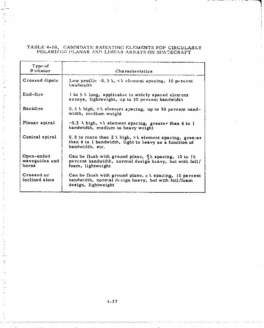
TABLE 4-10. C.ANDIDA_L:" o RADIATING ELEMENTS FOP CIRCULARLY• t:_OLARIZt;:D ]'LANAR AND LINEAR ARRAYS ON SPACECRAFT
: 'rype ofR "tdiato r Cha racte ristics
• Crossed dipole Low profile-.0.3 k, <k element spacing, 10 percenthandwidth
End-fire 1 to 5 k long, applicabie in widely spaced elementarrays, lightweight, up to 30 percent bandwidth
" Backfire 0. 6 X high, >k element s2acing, up to 30 percent band-width, medium weight
Planar spiral _0.3 k high, >k element spacing, greater than 4 to 1bandwidth, medium to heavy weight
Conical spiral 0.8 to more than 2 k high, >k element spacing, grea_,=erthan 4 to 1 bandwidth, light to heavy as a function of
• bandwidth, etc.
Open-ended Can be flush with ground plane, _k spacing, I0 to ]5waveguides and percent bandwidth, normal design heavy, but with foil/horns foam, lightweight
Crossed or Can be flush with ground plane,<k spacing, I0 percent: inclined slots bandwidth, normal design heavy, but with foil/foam" design, lightweight
4-27
00000001-TSD13

!. Table 4-11 lists the candidate feed networks. Open ended waveguideradiators are applicable when the feed network is also in waveguide,
. A helix, disc on rod, or yagi are very similar; they are end-fire radiators• extending above the ground plane by a minimum uf ] I/Z wavelengths. The: crossed dipole extends only 0. 3 wavelength above tile g,round p)ane, It can
be easily fed end-on from a stripHne feed. The backfire radiator is anextension of the dipole radiator by the addition of a second reflector. Ittoo can be connected easily to a coaxial connect,Jr.
The stripline feed with hybrid power dividers is a very commondevice. The loss per power divider is on the order of 0.3 d13, includingline length loss between hybrids. The loss of the feed network can bevery significant in an array of even medium gain. The circuit loss can beminimized by using rf amplifiers at each radiating element. However,
: this adds to the weight, complexity, and cost of the antenna system.
Another type of feed network is a stepped radial hne power divider.It is a parallel plate structure with a central feed point. The parallel plateregion is stepped in order to control the coupling to the pickup probes whichform the interconnect to the radiating elements. The radial power dividerprovides a tapered aperture amplitude distribution so that the aperture
i efficiency is 80 percent or less. With a loss of 0.3 dB in the powerdivider, the total antenna loss (including aperture mismatch and apertureefficiency) is on the order of 2.0 dB.
The flat plate slot array consists of lengths of waveguide with slotscut into the broadwall. The array of waveguides can be fed from anotherlinear slot array or from a feed network as discussed above. The linear
_ slot array is usually preferred, because it is compact and ideal for feedinga linear array. The array of linear arrays of slotted waveguides is most
i_ efficient when the aperture dimensions are greater than 10 wavelengths.The power lost in the terminations of the linear slot arrays increasesrapidly as the length of the arrays is reduced.
The flat plate annular slot array is a combination of the concepts orradial line power divider and a slot array. It is constructed as a parallelplate line, hut radiating slots are used in place of the pickup probes. Theaperture size is limited to a diameter not much more than 10 wavelengthsproviding an aperture efficiency of 60 percent. Circular polarization isnot easily achieved with slot arrays. Design and manufacturing costs arehigh for planar and annular slot arrays.
MDA Reflector Antennas
Several designs of mechanically despun reflector antennas can beconsidered. The cassegrain reflector is not included because it is ineffi-
• cient when the reflector diameter is less than 30 wavelengths. Dualreflector antennas, with the primary reflector mnaller than 30 wavelengthsgenerally have low radiatiou efficiency because of large aperture blockageby the secondary reflector.
: 4-28
O0000001-TSD14

T"
7., ......
!' TABLE 4-II. CANDIDATE ARRAY FEED NETWORKS
[
: Type of
i.... " Feed Networks Advantages and Disadvantages
_-- .- Stripline hybrid Lossy, area propc, rtional to number of radiators,_ -': power dividing custom design required; for linear, planar, or_- network circular arrays
_ " Radial line Low loss, custom designed for system; most appli-power divider cable to planar and circular arrays
}- -i, :. Slotted wave- Medium loss dependent on the length and number ofi : guide line- slots; suitable for feeding line sources_ source feed
_-_:" Quasioptical Large volume; suitable for feeding linear, planar_ " feed and circular arrays
i_!! .
i-/
i!?-= :,
:FL: -i ....
i:?
1 :
. ....i
i!i _ .
ri
O0000001-TSEO

I v_'---_. /_: __INTELSAT
ANTENNA V- (5) :0 SPIONEER VENUS J'_ORBITER MECHANICALLY / _,._" _DESPUN ANTENNA f
_ (,)_g22- "n
i O-- m< r_ m
ZZ 18 :,IGHT vs DIAMETER "4.
/ / _N..EAMWIDT" __ O•/
GAIN vs DIAMETERO
t-_o _(,,o) (_o_ (3o) (,o) (sm z
"! ' '_-_---r't.+--_ --Lt.....Jr---_-+--vu-r"Lv--"I20 30 40 50 fJO 70 80 90 100 110 120 130
REFLECTOR DIAMETER, CENTIMETERS AND (INCHES)
(UPPER SCALE ALSO HALF POWER BE_MWID'rH,DEGREES AT 2.3GHZ)
FIGURE4_19.PARABOLICREFLECTORPERFORMANCE- GAIN,BEAMWIDTH.ANDMASSVERSUSPRIMARY
4-30
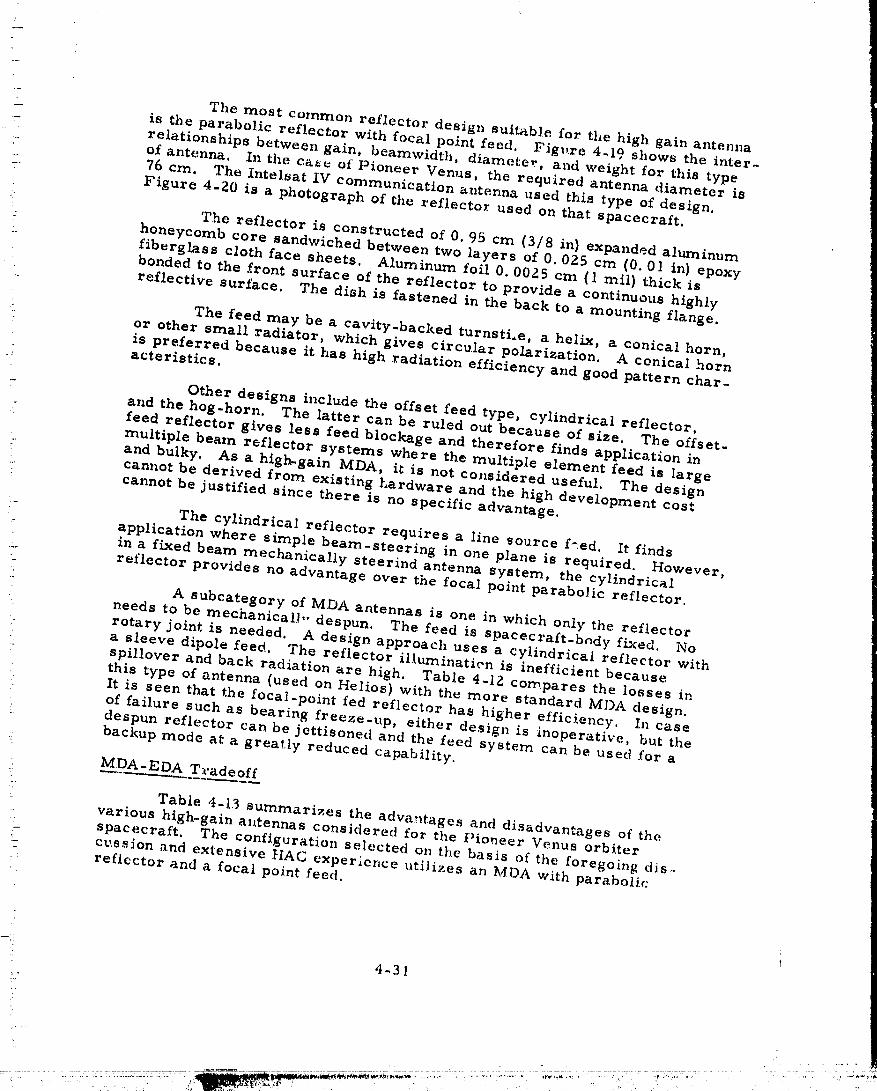
The most common reflector design suitable for the high gain antennais the parabolic reflector with focal point feed. Fig_,re 4-19 shows the inter-relationships between gain, beamwidth, diameter, and weight for this type
- of antenna, In the ca-_ of Pioneer Venus, the required antenna diameter is..... 76 am. The Intelsat IV communication antenna used this type of design.
Figure 4-Z0 is a photograph of the reflector used on that spacecraft•
The reflector is constructed of 0.95 cm (3/8 in) expanded aluminumhoneycomb core sandwiched between two layers of 0. 025 cm (0.01 in) epoxyfiberglass cloth face sheets. Aluminum foil 0. 0025 cm {I rail) thick is
• bonded to the front surface of the reflector to provide a continuous highlyreflective surface• The dish is fastened in the back to a mounting flange•
The feed may be a cavity-backed turnsti.e, a helix, a conical horn,: or other small radiator, which gives circular polarization. A conical horn
is preferred because it has high radiation efficiency and good pattern char-: acteristics.!
- Other designs include the offset feed type, cylindrical reflector,and the hog-horn. The lattercan be ruled out because of size. The offset-feed reflector gives less feed blockage and therefore finds application inmultiple beam reflector systems where the multiple element feed is largeand bulky. As a high-gain MDA, itis not considered useful. The designcannot be derived from existing hardware and the high development cost
: cannot be justifiedsince there is no specific advantage.
• The cylindrical reflector requires a line source f_.ed. It finds: application where simple beam-steering in one plane is required. However,
in a fixed beam mechanically steerind antenna system, the cylindricalreflector provides no advantage over the focal point parabolic reflector.
" A subcategory of MDA antennas is one in which only the reflector• needs to be mechanical],, despun. The feed is spacecraft-body fixed. No. rotary jointis needed. A design approach uses a cylindrical reflector with
a sleeve dipole feed. The reflector i11uminatien is inefficientbecausespillover and back radiation are high. Table 4-1Z compares the losses inthis type of antenna (used on Helios) with th_ more standard MDA design.It is seen that the focal-point fed reflector has higher efficiency. In caseof failure such as bearing freeze-up, either design is inoperative, but the
: despun reflector can be jettisoned and the feed system can be used for abackup mode at a greatly reduced capability.
MDA-EDA Tradeoff
i" Tabie 4-13 summarizes the advantages and disadvantages of the= various high-gain a11tennasconsidered for the Pioneer Venus orbiter: spacecraft. The configuration selected on the basis of the foregoing dis-:, cussion and extensive HAG experience utilizesan MDA with parabolic-- reflector and a focal point feed
-:! 4-31
_:-
........-:............... ............." ,,,,O00000 'TS_ .-:-........ , i_ ,
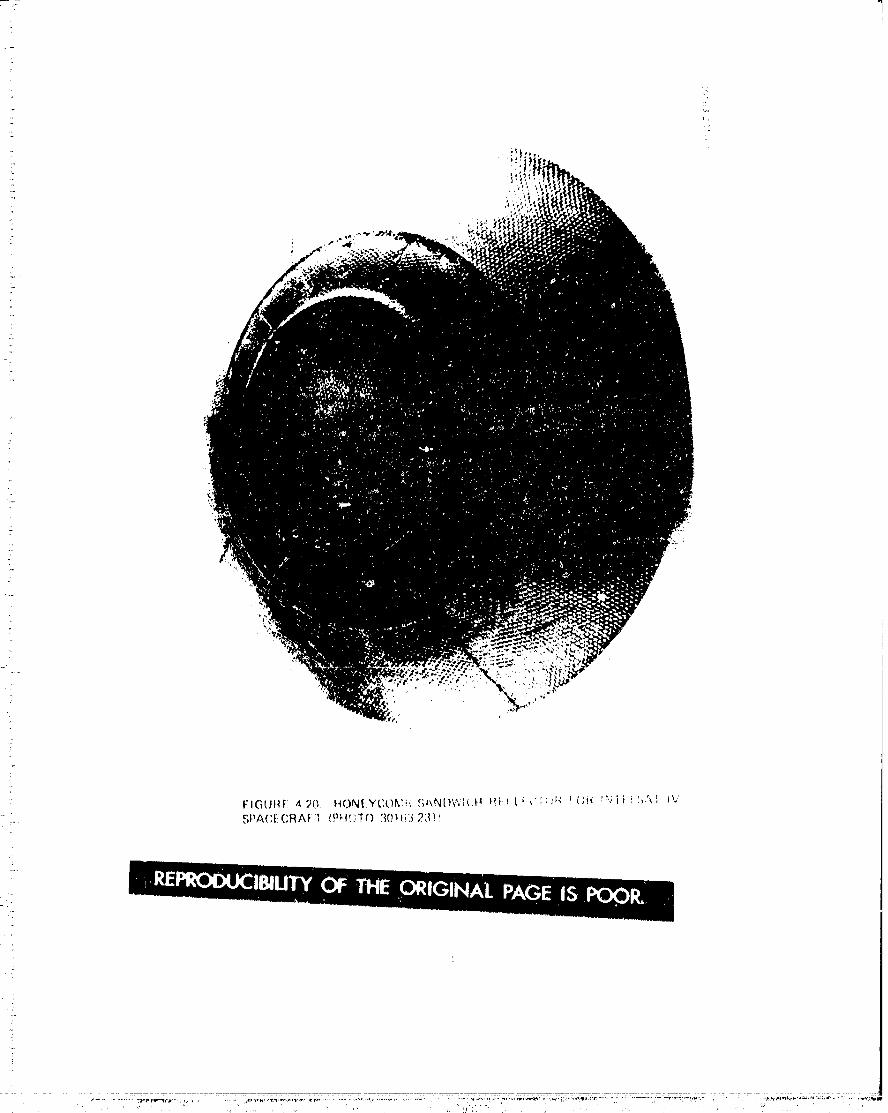
00000001-TSE04
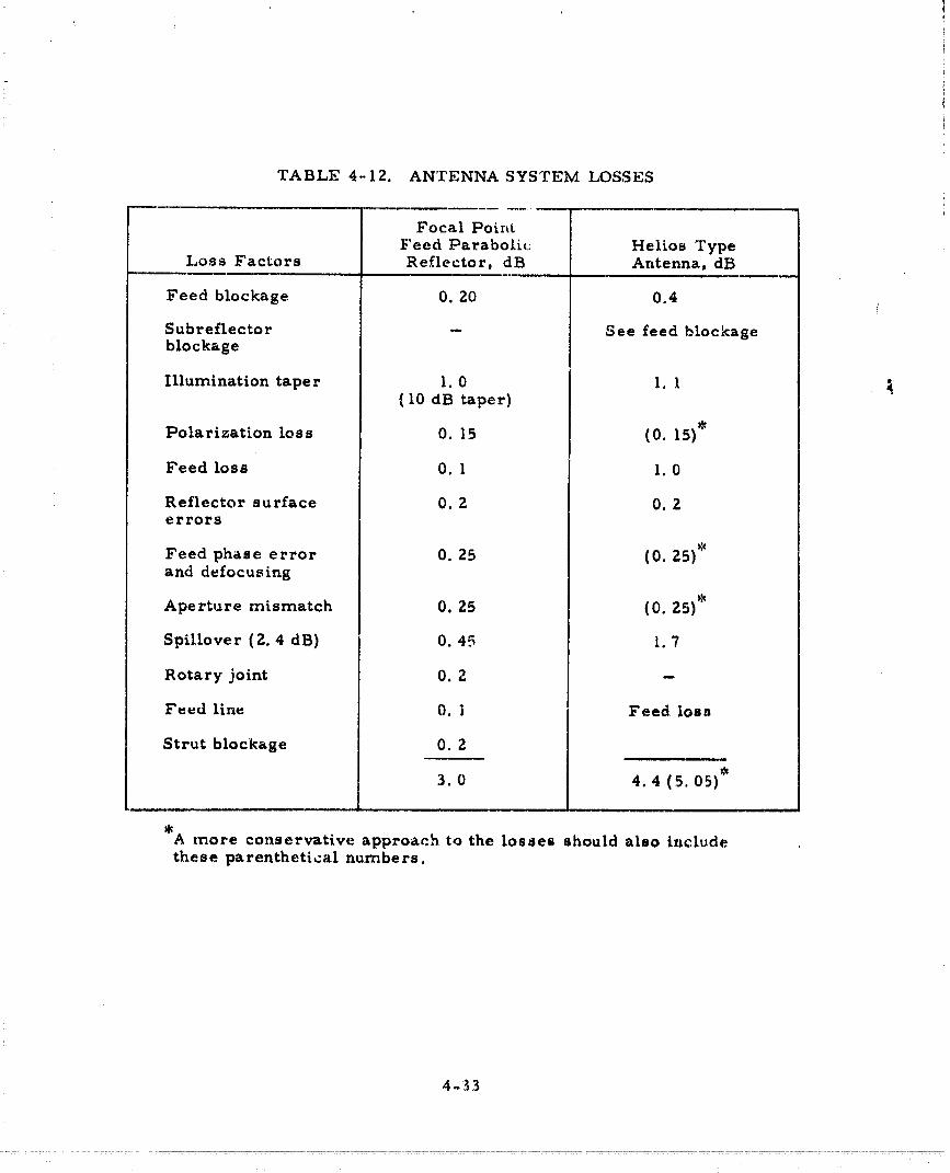
TABLE 4-12. ANTENNA SYSTEM LOSSES
Focal Point
Feed Parabolic Helios TypeLoss Factors Reflector, dB Antenna, dB
Feed blockage 0. 20 0.4
Subreflector -- See feed blockageblockage
Illumination taper 1.0 I.I(I0 dB taper)
Polarization loss 0. 15 (0. 15)*
Feed loss 0. l I.0
Reflector surface 0. 2 0. 2errors
Feed phase error 0. 25 (0.25)*and defocusing
Aperture mismatch 0. 25 (0. 25)*
Spillover (2.4 dB) 0. d5 I. 7
Rotary joint O. 2 --
Feed line 0. 1 Feed loss
Strut blockage 0. 2
3.0 4.4 (5.05)*
*A more conservative approach to the losses should also includethese parenthetical numbers.
4-33
00000001-TSE05
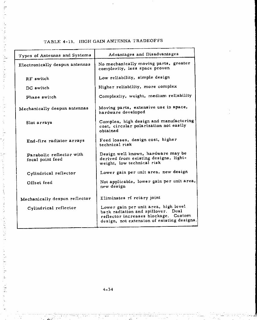
. TABLE 4-13. HIGH GAIN ANTENNA TRADEOFFS7
i.._ Types of Antennas and Systems Advantages and Disadvantages
Electronically despun antennas No mechanically moving parts, greatercomplexity, less space proven
i RF switch Low reliability, simple design
:- DC switch Higher reliability, more complex
:- Phase switch Complexity, weight, medium reliability
Mechanically despun antennas Moving parts, extensive use in space,hardware developed
: Slot arrays Complex, high design and manufacturingcost, circular polarization not easilyobtained
-::. End-fire radiator arrays Feed losses, design cost, highertechnical risk
:= Parabolic reflector with Designwell known, hardware may befocal point feed derived from existing designs, light-
weight, low technical risk
ii Cylindrical reflector Lower gain per unit area, new design
: Offset feed Not applicable, lower gain per unit area,new design
i"
Mechanically despun reflector Eliminates rf rotary joint
• Cylindrical reflector Lower gain per unit area, high levelback radiation and spillover. Dual
= reflector increases blockage, Customdesign, not extension of existing designs
7
.M
4
_. 4-34
00000001-TSE06

iz"
/' 4.4 POWER AMPLIFIER SELEC't'ION
-:- The objective of this study was to investigate the tide of a solid statepower amplifier rnodule that could be used as a building block to form any of
_: the required power ampiificrs in the probes, probe bus, and orbiter. A...... -- second objective was to perform a performance/cost tradeoff with a TWT.
i
....i .. The design choice for the Thor/Delta is a 7 W solid state power ampli=:_= . fier module, 'similar to that employed in a military space application. The-' design, which utilizes the MSC 3005 transistor in its output, Wil be space_:_" qualified this year. The module can be used alone as on the small probe,
or used in a parallel configuration which permits summing for higher power: in an external hybrid combiner as in the large probe, probe bus, and the or=
-:,: biter. This commonality of design aids greatly in reducing subsystem non-_: recurring costs. The power amplifier module can also be operated ina low-:,_ - power mode to conserve the spacecraft primary power. The Atlas/Centaur-:_ design was a 9 W module (see Section 6).
_ ) S-band solid state power amplifiers in the 7 W output range have only_< recently been developed for space applications. However, these applications-:;!::: are increasing in number, and space qualified components as well as actual
flight experience will be available within the next year,
__o:: Traveling-wave tubes (TWT) have had a more extensive application-_.: i history in space. Power outputs have ranged from 4. 5 to 24 W with a dual...... output power mode being a common feature of the higher power amplifiers.::_:-;L_ Much higher power tubes (100 W) are also space qualified.
-=:: A tradeoff between a possible 7 W, solid state power amplifier moduleand the TWT amplifier {TWTA)used on Pioneer 10 shows that the former is
-_ much lighter weight and smaller in size (see Tables 4-14 and 4-15). Efficiency::_. is roughly comparable. The cost of the solid state power amplifier should be=<_= roughly half of the TWTA. At this power level, only one factor favors the-,_ TWTA; namely, that it is "off the shelf" and has proven reliability in space_=,- application. However, if the TWTA were chosen for the orbiter rnission, or....._ - for the probe bus, commonality of design with the large and small probes:-_ would be sacrificed and costs would therefore be much higher.
=-: The power level is certainly a key factor H the required output power., : were greatly increased, a TW'rA would presently be the only available choice.
Obviously, performance of the solid state power amplifier is related" to cost whenever the state of the art is approached. For that reason, if less
stringent limits were imposed on weight and power consumption, the cost: would be less. A 20 percent cost reduction is estimated if the weight were to
increase to 0.7 kg (1, 5 lb) and the dc power requirement were 33.6 W.
i:_ Solid State Amplifier Versus TWTA Tradeoff
Table 4-14 summarizes the performance of variou_ solid state devices.... that ar,: of interest to this study. In the top grouping are integrated power
4-35
.
00000001-TSE07
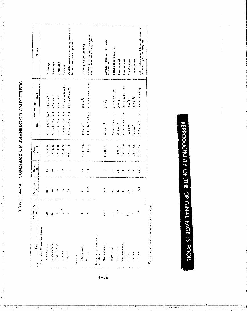
4-36
00000001-TSE08
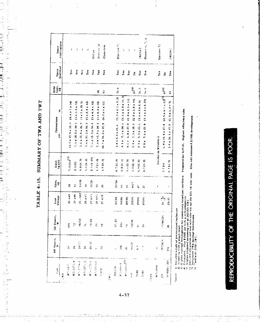

4- 38
_,..,.:...,_-.,...i.......... , ' 00000001 -TSE 10
if
• amplifiers which include an oulput i_olator and a regulating power suppl 7.: The second grouping consists _f exciter drivcr_ which have been or are about
to be used in space applications although at a somewhat lower power level,The performance parameters are for the r.ntire exciter. 2'he last of the three
:: groupings describes just the power amplifier itself. Note that weights and': sizes for these devices are very small,
Table 4-i5 summarizes information for traveling-wave amplifiers: (TWA), TWT, and TWT high voltage power supplies. In addition to those
listed there are previous generations of tubes which have flown on spacemissions. For instance, the forerunner of the 242-HAis the 242-H Whichhas flo_ on Mariner 69. It, in turn, was a selected version of a 394-H,which ha_ been flown on ApoLlo. Older generation Hughes S-band TWTshave also flown on Mariner 4 and 5, Lunar Orbiter, and Surveyor. Themost recent space appticatim_s are the Hughes 242-HA TWT mated with theWS1084 power supply, and the WJI171-1 TWA.
Additional information on both solid state amplifiers and TWT am-- plifiers is contained in a company sponsored I/_.&Dreport 4116.0Z/100 en-i'
:: titled "Solid State Versus TWT Transmitter Trade Study, " which is includedin Volume 15 of this report. Note that alldollar values given in this report
= are rough order of magnitude (ROM) and are exclusve of Hughes G&A and fee.
-:- 4.5 MICROMINIATURE TRANSPONDER SELECTION
A study was made to select a baseline design for a phase lock loopreceiver that is readily adaptable to the large probe, probe bus, and orbiterbus. Emphasis was placed on presently available space hardware or hard-ware which is already in an advanced stage of development. Since this hard-ware in some cases included the modulator/driver as part of an integrated
i_ transponder package, this survey was enlarged to include the entire trans-ponder.
Ithas been shown on a company-funded program that the transponderdesigned for the Viking Lander represents the most advanced design in pre-
: sently space qualified hardware. For the Thor/Delta application, the presentViking transponder would be repackaged to reduce weight and ease layoutconstraints Jn the large probe. This is possible because "footprint" con-straints, peculiar to the Vik_.ngspacecraft, forced the transponder to a non_
_ optimum integcated receiver-exciter package design. However, since theAtl.as/Centaur application is addressed to cost saving, even at some weightexpense, the Viking transponder would be used in its present configurationwith a minimum of modification.
i:
Various companies were cont_tcted for information regarding their:- communications transponder capabilities. Table 4..16 summarizes the data
which was obtained. Note that all costs arc R.OM and do not !nchlde Hughes- G&A and fee.
4-39
..... oouuuuu-,"'-----'-"-"'-
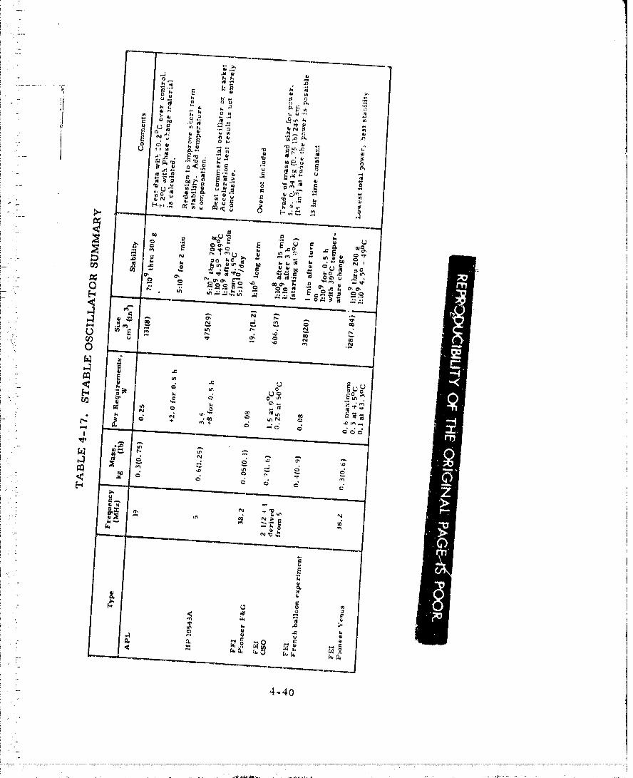
O0000001-TSE12

At the present Lime ti_e Philco microminiature DSN compatible Viking: transponder is clearly the lowest weight and lowest coat unit. The trans-: ponder _s based on a ,nodular design con,:ept in which the transmitter ;,nd
receiver are assembled frona modules into integrated units. All modules areof microelcctric hybrid d,tsign using either thin or thick film technology. Themodules are stacked one behind the other and mount_,d to a machined aluminuminterconnect chassis. *
The transponder has ,t built-in provision for cross strapping and theexciter has an auxiliary oscillator which can be substituted for the coherentfrequency input from the receiver. The Viking transponder design closelyfits the requirements of the Pioneer Venus mission and it will be possible touse this transponder wit'h a minimum of modification.
An alternate possibility is a microminiature transponder which isbeing developed by Motorola. Ultimatel/ this traxxsponder, which uses beamlead monolithic integrated circuits, is expected to be smaller and lighterweight than the Ph!lco-Ford Viking unit. However, its design is not yetcompleted and therefore it has not been selected for the baseline design.The two Motorola units which are represented "m Table 4-16 are muchfurther advanced in terms of availability, but as can be seen from the table,they are clearly less desirable than the Viking transponder.
: Additional information on the Motorola transponders, as well as theremaining DSN compatible units listed in Tabl_ 4-16 rt:ay be found in theIDC, "Deep Space Communications Transponder Survey, " included in Volume15 of this report.
4.6 STABLE OSCILLATOR
Experimental work performed at Hughes on a company-sponsoredprogram to evaluate oscillators for possible space applications is applicableto the selection of the stable oscillator for the Pioneer Venus small probes.Part of this work, "Evaluation of the Hewlett-Packard 10543A Oscillator, "is included in Volume 15 of this report. It is of interest to consider thisH-P oscillator for the Pioneer Venus application, since the unit is fairlycompact and has outstanding frequency stability specifications. However,as shown in Table 4-17, there was a frequency shift of 5 parts in 107 inducedby a 700 g acceleration. If this proves to be a general cha#acteristic of thistype of oscillator, rather than a chance flaw in the unit which underwent thetest, it would seem to rule out this type of oscillator for Pioneer Venus.In any case, the frequency will have to be non-standard for the Pioneer Venusapplication and this factor may negate e.ny cost savings whicb may otherwiseaccrue from selecting an off-the-shelf item.
Under Contract Ni._SZ-7250 from NASA/AB, L, the Applied Phymics.Laboratory of Johns Hopkins University is investigating a stable oscillatordesign for the Pioneer Venus small probe. Us)ng a crystal supplied byBliley, the APL oscillator has beeo run through a preliminary series of
4-41
" ' O0000001-TSE13
:_.- te_ts which iiJdie_att: that it i_ much t_.:s_ _cnsitive t_ ac:ct:l_:rat.ion _ forcesth;tn the tip _:ill;dc_r which *,w,._ t_,.sted at t[agllou. ']'ht_ nuntber rc,.t_orted ,
:- 7 parts in _,09 fc_r i]O(} g, is ._tiLl a iat'gt:," frt;queney shift than du_ired but• |_ecause the Mlort terln drift ir_ frequency was 5 part_ h-, 109 for 2 ndn, the. true _tability may haw.' bt:un l_aasked, 'lhe short term sta}JJlil.y of this
o,_cit)a,'-_Jr would haw_ to bc improved b_,h_re this type ,_f design could bcapplied to P_one_:r Venus, fhc API, o_cill,ttur developmcut is of particular
.: interest hi:cause cal.cul_tion_, ba_t;d on the use of phase change material fortempurature _'ontrol, indieat; that the oscillator would bc very _mall andlightweight. It would also require zr, ttch less powc;r thau the tip oscillator.
In addition to HP and Blilcy, a third rnanufacturer of high qualitycrystal o_cillators is Frequency Electronics Inc. (FEI). FEI also has thebenefit of expt:ricnce in space applications. As indicated in Table 4-17,
=-. FEI has supplied the 38. Z MHz crystal oscillator for the Pioneer. F&G pro-gram. FEIuses a patented crystal cut which allows 1 part in 106 stability
- over a temperature range of 20 ° to 80°C without any additional temperature:_. compensation.
FEI also supplies the master clock for the OSO-I program. The
i. power requirements shown in Table 4-17 arc lower than the actual OSO.... requirements. R.ather the table reflects the power which would be required- if the Pioneer F&G crystal oscillator were mated with the OSO-I oven.
:. Note also the tradeoff between weight and size on the one hand, and dc power_. on the other, Except for the rather long warmup time required for the _ta-- bility to reach 1 part in 199, this approach may satisfy the Pioneer Ve_s
mission requirements. It remains to be seen, however, how the FEI FC cutcrystal reacts to the high deceleration.
Another approach that FEI has taken is to provide a crystal with averylong thermal time constant enclosure. Because there is no oven, the
: circuit requires very little power and stabilizes almost immediately. Wittatriple dewar arrangement the oscillator, used in a balloon experiment by
the French equivalent of NASA (CNFS) had a _tability of 1 part in 109 for0.5 h and over an ambient temperature range of 30°C. The Pioneer Venus
: probe mission is about three times longer in duration and the: ambient tern-: perature change could be kS much as twice as large.
: Under the company-sponsor_.,d study mentioned above, FEIwas ableto perform an analytical and experimental study to develop and test aa o_cilla-
. tor meeting the speeification_ of Table 4-18.
A model 38.2 MHz oscillator was built and tested to demonstrate the
performance of Table 4-18. A single oven type with a duwar flask packagewa_ subjected to 700 g of acceleration. There was r_o appartmt frequency
: change immediately after the deceleration. Acceleration was applic'd in all_: six directions. No significant difference was observed,
: The test oscillator cry,,_ta[ wa_ an AT ctlt in a I'O-8 package, A pro-
posed flight oscillator would use ,:tn b'C cut crystal ;or better thermal per-furmance arnd a ':C '_ type holder re;" m:)re rigid mou_t:i_g. TY_z_ proposed
4-42
...... 1 TSE1...... ooooooo
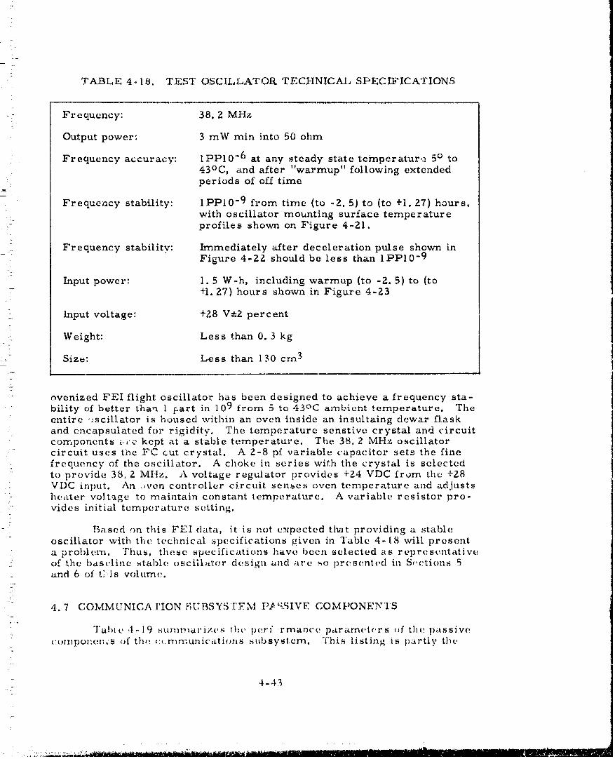
TABLE 4.18, TEST OSCILLATOR TFCHNICAL SPECIFICATIONS
,i: Frequency: 38. Z MHz
Output power: 3 mW rnin into 50 ohm
Frequency accuracy: lPP10 "6 at any steady state temperature 5 ° to43oc, and after "warmup" following extendedperiods of off time
Frequency stability: lPPI0 "9 from time (to -2. 5) to (to +1.27) hours,
: with oscillator mounting surface temperatureprofiles shown on Figure 4-21.
[
_ : Frequency stability: Immediately after deceleration pulse shown inFigure 4-2Z should be less than Il:'Pl0-9
Input power: 1. 5 W-h, including warmup (to -Z. 5) to (to+1.2.7) hours shown in Figure 4-23
input voltage: +Z8 V±2 percent
Weight: Less than 0.3 kg
:_ Size: Less than 130 crn 3
- ovenized FEI flight oscillator has been designed to achieve a frequency sta-bility of better than 1 part in 109 from 5 to ,i3°C arnbicnt temperature. Theentire "_scillator is housed within art oven inside an insultaing dewar flask
and encapsulated for rigidity. T.he temperature senst:,ve crystal and circuitcomponents t.,c kept at a stable temperature. The 38.2 MHz oscillatorcircuit uses the FC cut crystal. A 2-8 pf variable capacitor sets the fine
. frequency c-f the oscillator. A choke in series with the crystal is selectedto provide 38,2 MHz. A voltage regulator provides +24 VDC from the +Z8VDC input. An ,,yen controller circuit senses oven temperature and adjustsht_ater voltage to maintain constant temperature. A variable resistor pro-
" rides initial temperature setting.
Based on this FEI data, it is not v.xpected that providing a stableoscillator with the technical specifications given in ]'able 4-18 will present
a problem. Thus. these specifications have been selected as representative:: of the bast_linc ,_table oscill;_ttor design and are ,,,o presented in S,,ctions 5
and 6 of t;.is volume.) -
4.7 COMMUNICAI'ION V;[;BSYSI'.r'-TM [-'P'-',SIVE COMPONE3VTS
"J'abl e ,t - 19 sttmt_arizt,s l}_t, perf finance paramet¢,r s _,f the passive,::ompotzet_,s of th,; ¢:t, rr_n_uniclttions subsystem. This listing is partly the
4-,13
: .. ,, ,,; ,,..m_--_--- -....... _ ...... _.,._-- __,,,_ _ .-=--- ,. ,,,,
00000001-TSF01

,._.L--_.________ ...... : __ _,_a" ..........00000001-TSF02

[XS _ -+'O
_ ,_6 _ -I lwAtt _ +"WATT-HO
:_ to'2' o to -_TIME, HOURS
FIGURE4-23. POWERCONSUMPTIONVERSUSTIME
TABLE 4-19. RF SUBSYSTEM PASSIVE COMPONENTCHARACTER/STICS SUMMARY
Insertion Loss, dB Isolation, dB VSWR
Circulator-isolator 0. Z 25 I. 15
Filter, receiver bandpass 0.3 50 at fT l. Z5
Filter, transmitter bandpass 0.3 35 at fR 1.25
Filter, harmonic 0. I 30 at 2f T,3f T 1.15
Hybrid 0.3 23 I.20
Switch, SPDT 0.15 80 1.15
Switch, transfer 0.2 60 1. zO
Cable, 0.96 cm (3/8 in.) OD 0.20/m (0.06/ft) 1.100.36 cm (0. 141) OD 0.52/m (0.16/ft) I. 10
Filter, notch 0.2 40 at fR I..20
Rotary joint 0.1 l. 15i............. t 1_
4-45
00000001-TSF03

5
result of an. interaction with the rf ,:ul):;y._terP functJonM ¢!e._ign. Thus fc, r
( ' _)f lh¢: va_'_ou_ _iltcrs ;s (iictatted i,y tt_(: _....instance, Ihe i._.)la,i,m .%11. :iy _: a e,_T'_
.: design consideratitm_, lu ,,d, dili_n t.;; compi.ling the. _xpcct¢:d pe.rt.:.wn;_ncecharacteristics of the (:ommunicatiou ,.,:-;b'_ystem clt..nlents _everaJ. tra,/,eoffs
, : were performed to obtain _rptirnum da'_lgn performance. Mechanical _,,vitches:_ .. are preferred to fertile or diode switches when q}e number of _witching_-" events is relatively low because of the low insertion loss and high isolation,
The choice of a diplexer design based on incorporating a circulator at thejunction of the receiver and transmitter transmission lines is based on
- system as well as component considerations.
: :' Switche s
:
.. R.F switches are required to fulfill the functional requirements of.- the probe bus and orbit.er communication subsystems., 'Three types of
switches were considered: rnechanicM, ferrite, and diode, Diode switchesi
are very small and fast acting but suffer from relatively high inset%ion
,_ v IOSS. Moreover they require a holding current in one of the switch positions.:=,-
!: As an exatnple, one 2 C,Hz coax switch has 0.45 dB insertion loss and pro-i ...... rides 40 dB isolation with I. Z ma of current. The isolallun increases to
. 55 dB with II.9 ma of current. Although the currents are not large, the; insertion loss is prohibitive and therefore diode switches are least attractive
.. for the present applicat.ion.
; Circulator switches have been used in space programs. For instance: Wavecom makes a s,.(tch for the Viking program which has the following
_. specifications:
!
i :' Frequency 2. 2 .-2. 3 GHz
_'_. Isolation Z0 dB
i-: VSWt% 1. Z
_:.:, h_sertion loss -17,8 ° to -106.7°C (0 to 160°F) 0.3 dB
- 4.40 to ..17.soc (.3o o to 0°F)o. s dB
;v Power required 70 ma at 28 Vdc
_ _ Switching time 100 ms[..'
_: " Size 5. lx5 lx6 1 crn (Zx.2,xZ. 4 in)
One disadvantage _ of the clrcut,xtor sw'itcb _s lh,_ magnetic flux leakage.-:::. This is a_ao true, of an _rdinarv cite flator but a.s long _ s the magnetic fielde ,
is not switched, the leakage field n_ay be: con_pen.._ate.d: }towever, a circu-7. lator switch appe.a.rs ,_o be ineo**,patible with the use. ,')f a magnetometer on
l: board the spacecraft, ll). ;,ny v__ts;.:, the i_sevtior_ Loss is stilt quite high andthe isolation is inatffficienl when used to ,_witc.h rt7 energy h_,tweev-_ twoantennas whose antc;r!na Rains differ hy a mtmbe: appr¢_acbhx R the isola.tion
: provided by the .-witch.,
4 -46
'i"
Mechanical switches provide the lowest insertion loss and the highestisolation. Both Transco and Teledyne have made many rf swil.ches for
: space applications but Teledyne has also developed switches that are magne-
tically clean. These use mechanical latching drives rather than the morecommon magnetic latching drives. If magnetic cleanliness is not requiredthe magnetic latching switches would be preferred because of their improvedreliability and lower cost.
Teledyne's CS-Z7T60-3 is a transfer switch which was used on the iPioneer spacecraft. The switch weighs 0. Z8 kg (10 oz) and meets the
• ZO gamma residual field after being subjected to Z5 g field alongall three axes
;_'i_- 10 gamma residual field after demagnetization with ac field alongall three axes
_: ..-
Teledyne's CS33S6S-3 SPDT coaxial latching switch is being supplied
i_ to Thomson CSF for use on the Helios program. Magnetic requirements fori :i this switch are modeled after those imposed in the Pioneer program. Unlike
the transfer switch, which is vented, the SPDT switch is hermetically sealed.:-7-
_-_ Buth switches could handle rf power up to Z0 W.
_i A filter must be provided at the output of the transmitter to prevent_ transmitter generated excess noise at the receiver frequency from degrading
the receiver performance. The noise can either be generated in the exciter_ and amplified by the power amplifier, or it could be due to the noise figure_'_ of the power amplifier itself. In an experiment conducted at Philco-Ford,
: the Viking exciter output was coupled into the Viking receiver input by means
of a 30 dB coupler. No degradation in receiver performance was observed.Based on this measurement, the noise power at the output of a Z0 dB gain
.... power amplifier would have to be isolated from the receiver by at most 50 dB.
The specification of the Viking receiver states that the receiver must:: operate without degradation in the presence of a +20 dBm transmitter fre-
:_:: quency signal at its input. It more than meets this requirement with a five....- pole filter at its input which provides approximately 65 dB isolation. Thus
' _ the isolation provided by a simple circulator would be adequate if the Viking: receiver is used without an external low noise preamplifier. If however, a::: low noise (3.5 dB) preamplifier is required, the total isolation requirement::: . between transmitter and receiver would be determined by the preamplifier
_-_ saturation characteristics. With -_5 dBm at the pr¢,tmplifier input it should
i-::: be entirely unaffected. If then the transmitter output is +40 dBm, a total of65 dB isolation would be required.
4-47
00000001-TSF05

?
-z
There are a number of ways of configuring the rf communications• subsystems for Pioneer Venus spacecraft which lead to variations in filter: design requirements. The original concept pictured a diple.xer as a single
block which included the filtering required to prevent transmitter power
from leaking into the receiver; i. e., signal at the transmit frequency fT,and noise at receiver frequency, fr. Such a diplexer has been flown off'thePioneer F&G programs. This diplexer, developed by Wavecom, has the
= following characteristic s:
Frequency: transmit 3395 MHzreceive 2115 MHz
Passband 10 MHz minimum
Passband loss: transmit 0. 6 dBreceive 0. 76 dB
Passband VSWR I.25:1
Interchannel isolation 85 dB
Weight 0.9 kg (1.95 lb)
Size Z0.6x13.7x7. 1 cm(8. Ix5.4xZ. 8 in)
This is an integral unit and therefore it would not satisfy all the filterrequirements for the probe bus baseline design with its four separateantennas. Moreover the interchannel isolation requirement need not be
as high as 85 dB. In a diplexer with lower isolation and the same volume,the insertion loss should also be lower. Finally, the diplexer is quite
large in terms of packaging into the large probe. If it can be split intosmaller pieces it would allow greater flexibility in packaging.
This flexibility is possible if the diplexer consists of a circulatorand separate filters to provide addit,:onal isolation as required. Assumingthe circulator provides 15 dB isolation (limited by antenna mismatch) andthat at least this much isolation is provided between the various antennas,the most stringent filter requirement would occur in the case when aseparate preamp precedes the Viking receiver. In that case the receiverfilter isolation requiremeni: is 50 dB_ By careful design and fabricationtechniques it should be possible to limit the insertion loss to 0. 3 dB in afilter with a volume 557 crn3 (_4 in3). This represents a four section
stripline type filter. Fo. the filter in the transmit arm assembly 35 dBof isolation is required so *hat a Mmilar design would very easily bruitthe insertion loss o£ 0.3 dB. This distributed approach to the diplexerdesign was selected principally because it made probe packaging easier,
One can also consider the use of much smaller filters which have
: the attendant penalty of higher insertion loss. For instance the receiverfilter described in the Texas Instrument r,;port for the _,lectronically
4-48
00000001-TSF06

It )-
i--
?
i
i - despun antenna sy_,,m ":_provides approximately 45 dB isol_tion and has an;: insertion loss of O• 9 dB. On the other hand the filter is extremely small,i occupying less than 16• 4 cm 3 (I in 3) of volume. This reduction in volume; is not sufficient to justify the additional loss with the current subsystemf-:: design.
: Rotary Joint
i .... The rotary joint that is employed in the communication subsystem of;! , the orbiter spacecraft is a simplified version of the multichannel rotary joint; that has been developed for the Telesat program. The single channel rotary!- joint for the Thor/Delta design consists of the centred portion of the Te!esat}- rotary joint. This portion is a noncontacting, coaxial line design with rfb i" propagation in the TEM mode. The input/output connections to the rotary'- joint are consistent with the transmission line connections employed betweeni Z.
_. the rotary joint, the high gain antenna assembly and the rf subsystem, Thef
: noncontacting rf chokes at the rotational interfaces assure long life of thei _ unit. The only contacting parts are the ball bearings used to maintain ai :
!.: separation between the stationary and rotating portions of the rotary joint•i ;
i Circulator -Isolator
i .: Figure 4-24 is a picture of a 2. 1-Z. 4 GHz isolator which _s being! sic ace qualified under a military program and will be used for Pioneer Venus•i This isolator has a minimum isolation of 25 dB and insertion loss of 0. Z dB
from 4.4°C (40°F) to 71.1°C (160°F). It can also be operated at lower; temperatures, down to -Z3.3°C (-10OF) but the insertion loss increases to
:- 0. Z5 dB• The isolator becomes a three port circulator simply by replacing_- " the load, which is close to the scale in the photograph, with a coaxial
connector• The circulator-isolator dimensions are 5• Ix5.1xl•9 cm (ZxZx
. 3.4 in) excluding connectors. This may be contrasted with a lumped ele-menttype of isolator, such as the Trak Model 1_Z0-1310, which has a 20 dB
_: isolation, 0.4 dB insertion loss, but measures only 1 9xl 9xl 3 cm (3.4x, • • 0
[--" 3.4xl. Z in). Again, as with the filters, the reduction in volume is notf_ .: sufficient to justify the additional insertion loss with the current system_- design,ii
: Coaxial Cables
!: Semirigid coaxial• cables, to which the small OSM type of connector17" attaches, are available with various diameters At tow rf power levels the
' cable with an outer diameter of 0.36 cm (0. 141 J.n) will be used, However,
at higher power levels it is better to use the.: 0.95 cm (3/8 in) diameter coax.i .... This can be seen from the following consideration. The 0.36 cm coax
i . weighs 48 gins/meter and has an insertion loss _f 0.5Z dB/meter. The_. larger 0.95 cm cable has a mass of 136 gins/meter and its loss is 0.Z0 dB/
i : meter. Thus the "cost" of 0.32 dB i.s 88 gins. The rf loss must be compensated
i ( ::"R. D. iV[eeks, r*A_ Electronically Phased Modular Array for Pionerr Venus: Communications, " NASA/Ames Report U1-991 841)-F, 22 Now;tuber 197Z
: 4-4q


/
by additional output from the power amplifier which m turn requires additonal- dc output power. Assuming the power amplifier efficiency to be independent
of power output, the estimated pow¢;r drain increase, with an initial 7 W rf7 power output, is 1.8 W. This translates to approximately 135 gms of solar
panel mass so that the trade is clearly in favor of Lhe larger coax without:: even considering other factors such as possible increase in the power
i amplifier mass or the mass of the thermal control system. Thus, the.. larger coax will be used following the power amplifier_, Even larger .::pax- may be advantageously used on long cable runs butone must then take into:: account losses in the adapter between the OSM connector and the connector- which would be needed to fit the larger cable. OSM connectors are used on
the rf system components such as the circulator since the connector sizedetermines the he:ght of the component. The use of even larger coax forlong runs will be decided based on the particular situations.
r
4. 8 PROBE ENVIRONMENTAL CONSIDERATIONSf
The severe temperature and deceleration environments seen by the7 probes made studies of the impact of these environments on candidate probe
..... units mandatory.
_ H_igh Temperature Electronics
- To evaluate the performance of some critical elements in the probeat the end of the mission, their high temperature performance was considered.
. The acceptance temperature specification range of the present Viking Landertransponder is -It ° to +43°C. Its qualificationtemperature range is -Z6°to +57°C. Philco has also informally tested the transponder at temperaturesup to 70°C. At this high temperature there is some inevitable degradationin the performance of the transponder. For instance the noise teznperatureof the receiver preamplifier will increase about a half dB from its room
, temperature vahle. However, the noise figure at 21oc is typically about: 5.2 dB, well under the 6.5 dB specification, so that even at 70°C the Viking
receiver would meet 6.5 dB. Figure 4-Z5 shows the variation of noise figure:- with temperature in a similar Hughes-built preamplifier,
The power output of the Viking exciter drops by approximately 1• 5 dBi :- when the temperature is raised to 70oC. Over the acceptance test environ-
+0.8 dBi _ meets the present Viking specification calls for +Zl dBm -0 dB output•_ +I. 3 dBi _ This is relaxed to +21 dBm -0 dB over the qualification environmental
i : levels. These changes in power outuut can also be expected in the poweri amplifier Figure 4-26 shows data obtained on a MSC 3005 transistor ampli-
fier circuit. Power and efficiency both drop with increasing temperature.: L_ this experimental amplifier the 7 W power output was obtained only at
' _:- temperatures below 43°C. (h_e could obtain a more constant output power bydesigning the regulator voltage to decrease at lower tempezature but in this
•_ case at least, one could not further raise the voltage at high temperature: since the power dissipation requirement on the transistor would become
excessive,.
i 4-51E
i ....
...........................................: , .... ..........................................' ....:...... "............. ::: "00000001-TSFO!
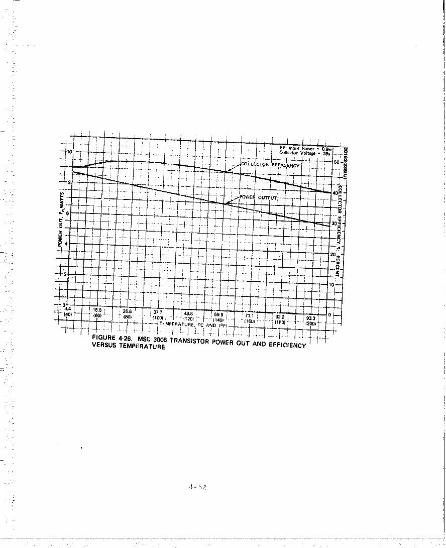
,io
TSFI(-_-'_.............................................................' ..... 00000001

: A third deterioration in the present Viking transponder performancei8 due to frequency drift with tenqperature of the crystal oscillators. Theexciter auxiliary oscillator uses an AT cut uncompensated series resonantthird overtone crystal. The frequency uncertainty specification_is _1.3 parts
: in 105 during acceptance t r.st environments and _Z. 0 parts in 105 duringqualification test environments. Identical frequency uncertainty requirements
- apply to the receiver best lock frequency. The frequency uncertainty willincrease yet further at higher temperatures.
The filter_ used in the Viking transponder, as well as elsewhere in• the large probe communication system, are relatively broadband so that
their performance will not be greatly influenced at temperatures up to 77°C(170OF). _"he coaxial cable leading to the antenna terminal from the rf sub-system will not only convey the ,nicrowave signals but also any heat whichmay be present at the antenna terminal. Hughes Aircraft Company TIC4116/73/051, "Probe Antenna Development, "included in Volume 15 of
, this report, points out that the antenna materials are selected to withstandhigh external temperature environment of 765°K. The antenna itself wiilprovide some thermal impedance between this outside temperature and therf subsystem. If further analysis indicates it is required, the coaxialcable will be designed to further isolate the rf subsystem from this hightemperature. This is done by using silver plated thin wall stainless steelcoaxial cable. A preliminary calculation shows that this approach could
: reduce the coaxial heat lea_ into the probe by a factor of 100 as comparedwith standard 3.5 mm diameter coaxial line.
High -G Electronics
The communication system components on both the large and smallprobes will be subjected to a high g environment during entry into the
_: atmosphere of Venus. A possible deceleration profile for the small probeis shown in Figure 4-22, The communication system must be designed tosurvive this pulse. Due to ionization of the atmosphere, the communicationsystem will in any event be "blacked out" during the deceleration itself.Thus the components need not be tested for normal ope. "tion during the highg period. They will however have to survive the high g and be fully operative
: immediately afterwards.
As described in the Hughes Aircraft Co. TIC, "Electronic ComponentHigh-G Evaluation Tests, t, included in Volume 15 of this report, componentassemblies of various constructions were subjected to high g test levels.Point-to-point and printed circuit constructions are used in the communica-tion system power amplifier and receiver/exciter. The test showed that
: the circuits did survive the high g envirol_ment. However, as described in- Subsection 4.6, permanent frequency shift of 5'. 107 was experienced with
the Hewlett Packard high stability quartz oscillator. A temporary frequencyshift during the high g period is unavoidable. It is the permanent changewhich must be avoided. The oscillator in the cross-.strap converter did notchange frequency after being subjected to the high g but the accuracy of themeasurement was limited to I'.10 8 . The stable oscillator which is beingdeveloped by the Applied IC_hysicsLaboratory of Johns Hopkins University
4-53

7,_-
,i
_7
: under NASA/ARL Contract NAS 2-7250 has been subjected to 300 g level andits frequency changed less than 7:109 - again the limit of measurement
i: accuracy. Further tests conducted L_nd, .c a eolvApany-ftmded program demon-.- stratod that an oscillator with the requisite ].10 _ stability will maintain that- ci:arac_eristie in the face of the high g environment.
!
The major corr_ponent in the baselir_e large probe communicationsystem is the Viking tr_tnsponder ;_nd in the small probe it is 1he exciter
- portion of that transponder. This transponder h_s been tested to 1500 g.... shock level. Th_ anticipated 700 g deceleration requirement is expected to= be tess severe than the shock requirement and therefore it is expected that• the Viking transpondcr can be used "as is" from this point of view.
?i
4-54
O0000001-TSF12
r.
T
- 5. THOR/DELTA BASELINE.%
...... The criteria for selecting the commuuieatiou system components'._ for the Thor/Delta ba_line were based on achieving the lowest possible
:- cost within the weight and performance constraints of the subsystem re-- quirements as they were formulated at the midterm design review in..... February 1973. To achieve low cost the greatest possible design common-
ality between the orbiter, probe bus, large probe, and small probe was'' _ implemented with component hardware which to the greatest extent possible
,' : was directly derived frorr, other space programs. Table 5-1 illustratesL._ this philosophy. Note that the only completely "new" hardware items are
- the stable oscillator and the probe antennas.
..... The communications system is divided into the radio frequencyi
i....... subsystem and the antenna subsystem. Details on the design of these':_. subsystems is given in sections 5.1 and 5.2, below.
5.1 RADIO FREQUENCY SUBSYSTEM
Probe Bus
!-- " Figure 5-I is a block diagram of the rf subsystem proposed for!
i the Thor/Delta probe bus. The diagram also shows the connections and'_: rf powers delivered to the various antennas. Note that there are three rf
___ power operating modes which are referred to as 10, 5, and I W modes,even though these are only approxirrations to the exact powers delivered
] :.
i_ _ to the antennas. In the I0 W mode, both power amplifiers are turned on:: and their outputs are added in the summing hybrid, lu the 5 W mode only• one power amplifier is turned on so that fullredundancy is available. In
the l W mode the power amplifier is operated with reduced voltage applied: to the transistor so that power is conserved. This low pov_ r mode is
required by the type II orbiter trajectory when the spacecraft is greaterthan one AU from the sun. All three power mode_ are available to the
• horn, bicone and wide beam omni antennas by suitable selection of switch: commands. The narrow beam omni is used for transmit only in the 5 and
, _: 1 W modes.
Either of the omni antennas can be connected through a diplexer and• _- the transfer switch to either one of the _,_reamplifierrecei,,ers. The
5"
i....i:..... 5-I
i ....
!
! _ ...... i - i i. iiI i i i HI
00000001-TSF13
7'
t TABLE 5-1. GOMMUNIG.ATIONS !IARDWARI! DI,;RIVATION
[;Rtl |)FO_H' J_q_ [ {)2t){ll.r J,;_r;',r" I £'HJ_r. ._rl,ll[| l'r.)lw
[_n{_ flnll .*
lligh gatn NA I*Im,.l_.l IV NA NAI rnqd_fy fP,'¢pJP'_ _,
I |ll'_lllWldth, ji,i.ri,"_,_11JIIPI }_allll'a]
inl;c' r fee ['
Bi¢on¢ :::f)ata _yut_,nu_ NA NA NAnmdlfy iroq...nry,!)¢'_IIIW I¢ith, P-[1¢Ill_echanica| illtPrflit L'
Wide an_le omni- _4. htrvuyor aiiirr_, ,t_ probe b,z_ NA NAdiroctio_lal (con,ical croas_,l ah)ts)
Narrow beam omni :':IIS-tSO San-e as probe I)u,_ NA NAdirectiona! icon- n_odify frequencyical _,piral) and beamwidth
Medium b_am horn *lntelsat IV NA NA NA
modify frequencyand beamwidth
Equiangular spiral NA NA New (in NAd,._,,.l den:ant )
I, OOp- yea NA NA NA N,'w (in
development
Rotary .joint NA *'Ielesat NA NAmoth fy frequency
and simplify tos ingh. channel
Receiver/exciter Viking. rt.packa2e ViMn_, r..oacka_:t. V!ktnR, r_.pacha;_. NAtO reduce, weight to Pe(]_le(' wl'il_ht tO redllce WeibQ:t
EXCiter NA NA NA Vi_ing, with -kyn,'tpacks R_ni2
Switche_ Pioneer, Helios Same as probe Ires NA NA
POwer &nlplifier "'Military program Sa,':,e as probe h,_s Sa:_:e :is probe i)u_ Saner as probe b_,sIncrease _aia,efficience, decrease
pO',v¢' P, Weight
Preamplifier *Brazilian Same a._ probe bus Sar:_,.as pr,9,)e bus NA"i' g_d e int(,rm_d
for P_i_c figure
Filters:
BanOpass A'I"S_E San;e a,_ pr:q)e hu_ 3ame as pr,)b_, )u_ NAModify frequencybant]_,,idt h
Low pass *r ele_al
Modify frequenty
Notch NA *I'vh, sat NA NA
Modify fr_,nu,,n(
Circulator *080 5amy a_ probe bUS Sa_l(' aS Dr'_h_' l)u._ N__,
Stable oac illator NA NA NA Ne_
* Existin g HAG proaramaa,_ Previous HAC pr_._ram
- 5-2
O0000001-TSF14
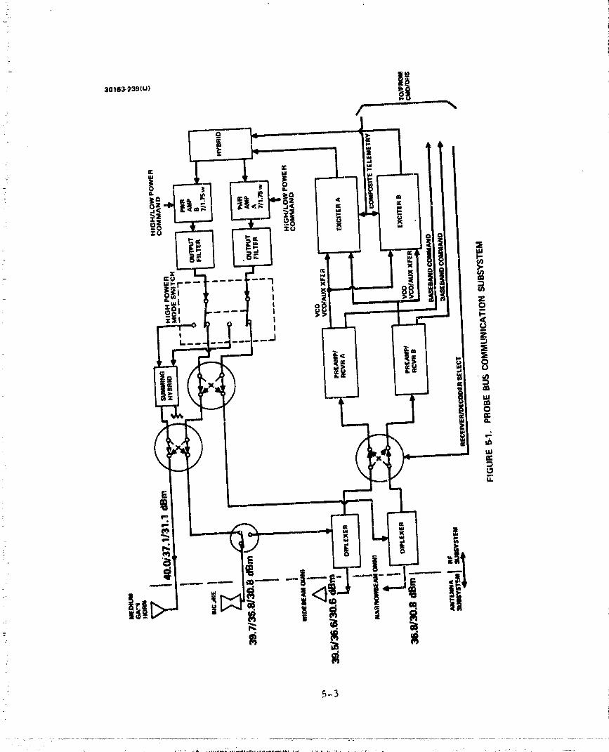
: 5-3
00000001-TSG01
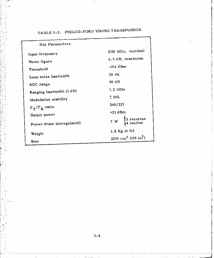
)- .
! . -
i̧:T/_-) z:.
TABLE 5-2. PHILCO-FORD VIKING TRANSPONDER
!: Key Parameters
i' : Input frequency 2115 MIlz, nominal
!2:"!_ Noise figure 6.5 dB, maximum
i-:..,"" Threshold -154 dBm
!--:: Loop noise bandwidth 20 Hz
)_.,._._ AGC range 90 d B
i-,' Ranging bandwidth (IdB) I.2 MHz
i, Modulation stability + 10%
_-!"i FT/F R ratio 240/221[:.):'f;
i-2,_- Output power +21 dBm
)-_: receiver
i_ ' Power drain (unregulated) 7 W exciter
i _ Weight 1.8 Kg (4 lb)i!" ; Size 2210 cm 3 (135 in.31
[-.. "
)L!-
j-'_ •
?_',J,
_ _ tfdiph:xert' contains a circulator and a receiver bandpass filter, the
i__ combination providing 65 dB isolation to the transmitter frequency, The
_ ._ 3.5 dB noise figure preamplifier is a separate unit which improves theoverall receiver sensitivity. The remainder of the receiver is actually
-. part of the Viking transponder whose principle characteristics are summ-
arized in Table 5-2. The transponder has builtin provision for cross.. strapping. Since both receivers are turned on at all times the exciter
output is determined by either receiver VGO, or if neither receiver is"_.... phaselocked, by its own auxiliary oscillator. Only one exciter is turned
_ on at a given time.
Tl:e power amplifier is a solid state module capable of providing: either 7 or 1.75 W of rf power. In the higher power mode the amplifier
has 20.7 dB of gain. Switching between these modes is accomplished by• an internal regulator which switches on command to _ lower dc voltage
_ for operation in the 1 W mode. The power amplifier includes an isolatorat its output to provide protection from high VSWR during switching between
._°_i,- antennas and to the I0 W mode.
_ The output filterincludes a low pass filterto suppress higher_ harmonics of the transmit frequency, and a transmitter bandpass filterto
i_,: suppress noise power at the receive frequency.
_;- The output powers are based on the insertion losses indicated byY
L Table 4-19 in subsection 4.7 of the tradeoff studies and by estimated cablek..... lengths between the rf subsystem components and the antennas. Similarly,i"'_- the system noise temperature is calculated to be 570°K.
.L
Table 5-3 summarizes the power, mass, and size of the rf, subsystem.
Orbiter
_--< Figure 5-2 is a block diagram of the communication subsysternfor the Thor/Delta orbiter spacecraft. The similarity between this andthe probe bus is very obvious. Moreover, this is true not only in the
" block diagrarr:but also in the physical sense. Even cable lengths andcomponent ]-.yourwould, to the greatest extent possible, be identicalonthese two spacecraft.
The principal difference between the orbiter and probe bus,, . communication subsystems is that the former has only three antennas.
The high gain and widebeam (dcspun) omni antennas can transmit in anyof the three power rhodes. As with the probe: bus, the narrow beam
i-, (spinning) omni can transmit only the 5 and I W modes. In order to trans-mit on the despun omni the rf switch following the circulator is connectedto a short circuit and thereby reflects the power back into the circulatorand out of the omni. For r'_- ' ,c_,elw,,the signal from the despun ornhi passes
.-- through the circulator directly to the rotary joint (R J). The purpose ofthe notch filter {NF) is to prewmt interferometry effects in the rece._ved
- 5-5
. ,h¸ ,_ , ........ ,, ,. • ,' ' ..... _. _ # ,,;, • ," " .' , ....
00000001-TSG03


00000001 -TSG05
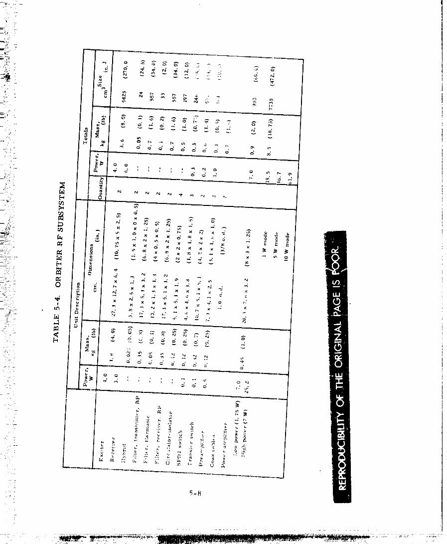
00000001-TSG06

:T
: beam pattern of the high gain and despun omni antennas. This is necessarybecause the high gain antenna gain exceeds the despun omni antenna gai.nby a number comparable to the is()lation prc)vided by the circulator.
:- However, with the addition of the notch filter which rejects the received
: frequency, this destructive interference cannot take place,
Table 5-4 surt,marizes the power, mass, and size of the rf sub-system for the orbiter spacecraft.
Large Probe
Figure 5-3 shows a block diagram of the rf subsystem for thelarge probe. In essence it is a non-redundant, single antenna, 10 Wmode only, version of the two previous subsystems. The filter at thetransmitter output is now shown in its corriponent parts, as is the diplexer
: and the preamplifier receiver. The component parts are identical to_ those used in the probe bus and orbiter except for the power amplifier
which is lightened by deletion of the internal regulator. This deletion ispossible because the duai power operation of the power amplifier is not
: required and the large probe power system provides a regulated +23 V,exactly what the power amplifier requires for 7 W output power. The rfpower amplifier circuit is, however, identical to that used in the probebus and orbiter.
In this case isolators were not provided at the power amplifieroutput in order to keep weight at a m,.'nimum. This means the system, as
" shown, is susceptible to high antenna VSWR, because the reflected trans-: mitter power will simply circulate through the circulator, reflect off.... the receive bandpass filter and thence back into. the power amplifier.
This situationmust be avoided, either by turning offthe transmitterwhenever the antenna is mismatched to its load (as during the start ofentry into the Venus atmosphere), or by providing an isolator somewherein the line. This could most conveniently be done _"itha four port cir-culator-isolator in place of the three port circulator shown. However,for the midterm baseline design shown in Figure 5-3, the large probe wouldhave to operate in just the same way as the small probe where isolato_'n
" are banned because of the magnetometer experiment, i.e. the power• amplifier must be turned off during communications "blackout" at the
!" start of entry into the Venus atmosphere.
" T'_ble 5-5 summarizes the rf subsystem components on the largeprobe.
L
Small Probe
: Figure 5-4 shows the rf subsyst_m block diagram of the Thor/: Delta small probe, 'r}",c 7 W power amplifier module is identical to the
module used it_ the lar,_e prc_be. Th(, exciter i:_ the _,_citer portion ofth_ Viking transponder except that the auxiliary oscillat,_r was deleted
7" 5-9
00000001-TSG07


/
.
I-
?W
..T,.. _ r_,_--_,I I L'-_-_---JI /_',)q"_l:'it[1:_'_ I<1-'tXMTR pIP-,IHYBRID / _HYBRIO]"
2.
.
_1_EV R " -- +21 dBmBP PREAMP RECEIVER EXCITER
FIGURE5-3. LARGE PROBERF SUBSYSTEM
•O,..E,,, I,OW, l �Ô�II .,. M.. STAILE+38.3 dBm-_ AMPLIFIER __EX._ OSCILLATOR
" 7W
: FIGURE 54 SMALL PROBERF SUBSYSTEM
5-I]
00000001-TSG09
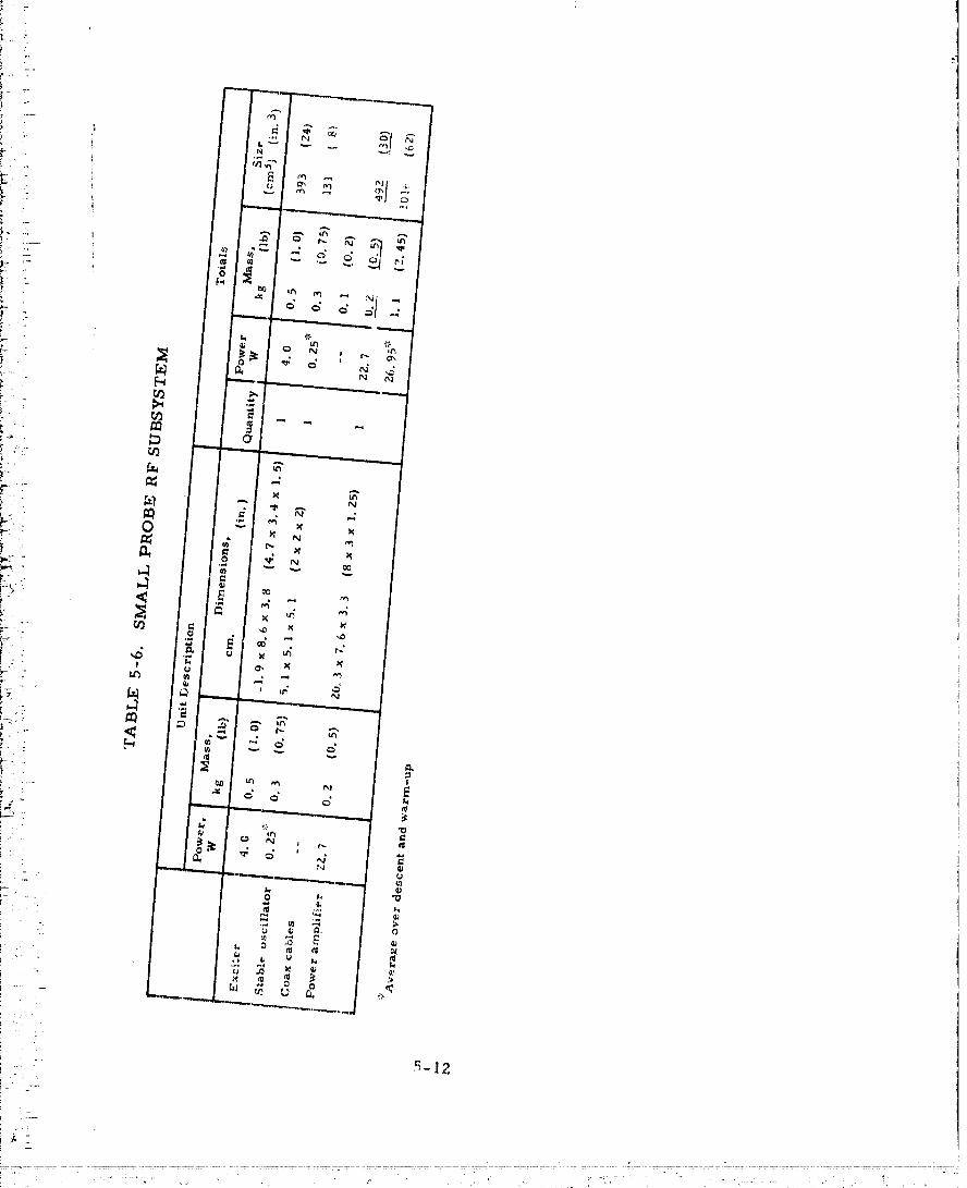
O0000001-TSGIO
and a 3 dB pad is substituted f(_rthe output isolator. The pad slmplyrenorma!izes the exciter output pov_r t¢_the value required by the poweramplifier module. At the same. time itprovides sorrlcisolationbetweenthe excite:routput and power amplifier input. The exciter output isolatorcannot bc leftin the circui_ sin_-cin this version the magnetometer ex-
periment is carried on the small probe. Finally, the exciter is rcpackagcdto a minim_._m 3.8 cm height dimension so as to obtain minimum size andweight for the small probe.
The stable oscillator is included here as part of the rf subsystemalthough it might very well be considered as part of the experimentspayload. The oscillator is designed for l part in 109 stability duringdescent into the Venus atmosphere.
Table 5-6 summarizes the component parameters for the small
probv.
5.2 ANTENNA SUBSYSTEM
Orbiter
The orbiter spacecraft uses a mechanically despun parabolic re-flector antenna for high gain and two broad-beam antennas to provideessentially spherical coverage. Table 5-7 summarizes the performanceof these antennas.
The parabolic reflector has been selected because of its lowweight, design/implementation simplicity, low technical risk and low-level development required. An electronically despun array would havebeen heavier, more complex and had higher technical risk. A mechani-c_lly despun _a_-ray is c,_stly dtle to complexity. The hi_,,h gain antenna isa focal point fed reflector based on a flight-proved communication antennaof the Intelsat IV program. The antenna circuit losses consist of the lossin the rotary joint, the feed llne from the rotary joint to the feed, andthe ohmic loss of the feed. The aperture efficiency loss is due to theeffects of the aperture taper, reflector surface tolerance, apertureblockage, spill-over and feed location tolerance.
t
The reflector is constructed of 0.95 cm (3/8 in. ) expanded aluminun_:
honeycomb core sandwiched between two layers of 0.25 cm (0.01 in.) epoxyfiberglass cloth facesheets. Aluminum foil 0.0025 cm (1 rail) thick _s bonded tothe front surface of the reflector to pro,,_{de a continuous highly reflectivesurface. The dish is fastened in the ban,, to a mounting flange, The feed is_, conical horn, probe-excited to produce right-hand circular polarization.The conical horn is selected over other candidate feeds, because these
antennas provide good axial ratio of the secondary pattern, have highefficie,:cy and low backlobe radiation.
A conical log spiral and a slotted cone antenna were used in com-bination to provide spherical coverage. These antennas have been selected
5-13
O0000001-TSG11

i i:
"" on toe basi_ of cover;_go/spac.t:craft, int_;r_t_'r_u_cv, avaUxinltty and lt_wi.:..... 7 weight:. Th_ ._l_tted cot_¢' is l-ht_ sam(; i_trdor_fla tl_,ai_2,t-t _lSo¢| oil the Surw:yor
;., spat, e_:rafl. It l,r,,vide;i l_¢:liel" ihan henai-.slJh, ei_.:al (:over;iRe and thertff¢)re". ' i_ located above lilt, reflecl_r al-llt, nna |(} gi_v( ' i.l it XVidl' unol)slructed viewi': angle. Tilt! ctmic_xl log _piral is d,_si_,nod I_) fill in Ihc partial hv.rnispher/_!_:'. " not cow!r_,d by th_ 5urveyor-ornni patlx, en. 'l'h¢, c_,nieal log spiral consist,,
-- of a conducting ribbon Wt)ILIaf] ()n all apo.'.:y fil)orRlass con(,. Table 5-8! .. summarizes the orbite.e ant(-,nna subsy._t, em [Jarant('tt,.r,_.? ,,
:: := AS seen Irom the spacecraft configuration, b'igure 3-2, the logconical spiral ornni is spinning with the spacecraft. 'I'h_: ,_lotted co_r
"; omni mounted above the high gain antenna is despun. It is rnor_: convenient:F : to mount it in thai: manner, than on a separate space, craft body fixed mast.
_ On the probe bus spacecraft, the location, of the two wide angle coverage!" antennas is reversed from that on the orbiter to minimize obstruction/
- shadowing by the spacecraft body/structure.
: Probe Bus
i'
_' " The probe bus antenna assembly includes the deployable bicone,! medium gain conical horn and the omnidirection;,1 antennas, Table 5-9L is a listing of the performance characteristics of the probe bus antenna
i assembly.
i_ "i_he bicone antenna gives an omindirectional coverage in the spin
_:_ .... plane w.,th a half power beamwidth of 30 deg. along tile spin axis. The, net gain is not less than 3 dB. A similar antenna has been built and.... tested at a higher frequency verifying the characteristics of the bicone
.. antenna. The circular flared region is excited by a ring of crossed'" dumbbell _lots located on the circumference of the circular waveguide..... feedline.
The bicone antenna is retracted during launch and is deployed after
' separation. The deployment mechanism is electromechanical. No rf-_ :. moveable joint i_ required. A length of flexible coaxial cable provides the
extendable rf connection,!i
' The mesium gain antenna is a circularly polarized conicM horn
: with a polarizer and a transition from rectangular to circular waveguide.E_dfire radiators were considered but rejected, because such an antennai ' would have to be mounted away from the vehicle to avoid shadow!ng oni : the r_.diator. A flat array is complex and becornes inefficient in this range
_ " .... of gain. The horn is a frequency scaled version of the earth coverage horn
i - used on Int:elsat IV.
,,, 'the omnidirectional antennas are the sa_u design as used on the
orbiter spacecraft.i :i .
i ....
i "
, 5-15
/
..........00000001-TSG13
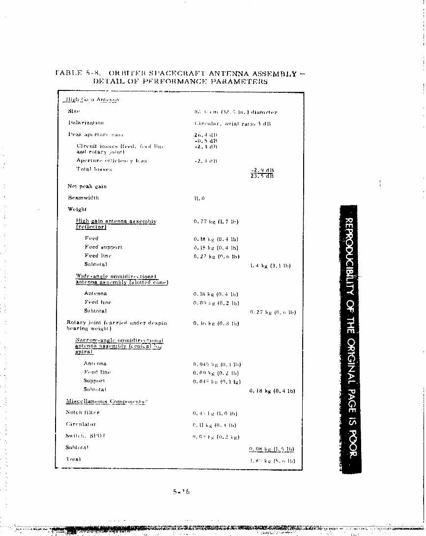

--- J c_° c_
• 0-0000002
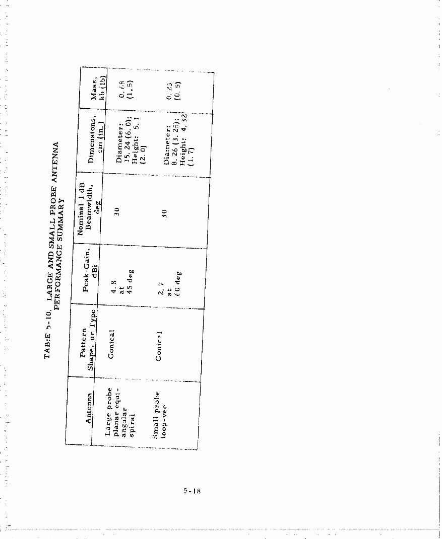
7
5 - 1t_
00000002-TSA03
Large _ Probe
The antenna on the large probe is a planar four-arm equiangularspiral, similar in de_igr_ principle to the conical log spiral used to providenear hemispherical coverage. By feedin_ the four spiral arms in phase,a near hemispherical pattern results. When a 180 deg. phase change iscreated between adjacent arms, a conical pattern results with the patternpeak occuring at 50 _+ 15 deg. The angle of maximum gain is a function ofthe ground plane and spiral growth rate. The characteristics of the spiralantenna designed for the large probe are given in Table 5-10. The antennaconsists of a circular cavity c_,osed off at one end by the spiral circuit andat the other end by the one-to-four port hybrid feed network. The cavityis fill-,] with high-temperature foam to give support to the sp._ral circuitagainst high pressure loading.
Small Probe
The antenna for the small probe is a loop-vee radiator chosenbecause of its small size, low weight and good patte:n performance. Itscharacteristics are given in Table 5-10. The antenna consists of fourinclined monopoles each feeding to a quadrant of a horizontal loop. Theantenna is very simple in construction and suitable for operation in adverseenvironments since only a conductor material is used in the construction ofthe radiator.
5-19
00000002-TSA04

q6. ATLAS�CENTAUR BASELINE l
t
The criteria for selecting the communication system components forthe Atlas/Centaur baseline were based on achieving the lowest possible cost_
since unlike the Thor/Delta design_ weight was not as serious a constraint.Also_ the Atlas/Centaur baseline reflects changes in the subsystem require-
ments up to the present writing. The greatest possible design commonalitybetween the orbiter_ probe bus_ large probe_ and small probe was imple-
mented. In addition_ most of the component hardware wa_ directly derived
from other sFace programs as shown in Table 6-I. Note that the only corn-pletely "new" hardware items are the stable oscillator and the probe antennas.
Changes between the _ihor/Delta baseline described in Section 5 andthe Atlas/Centaur baseline described in this section are due to four factors.
The first is, of course, the change in launch vehicle from Thor/Delta to
Atlas/Centaur. The second factor is the change of mission set. This changeimpacted the design of the communications subsystems for the multiprobemission since the communications ranges at the mission critical events were
changed. A third factor is the new nominal science payload associated with
the new mission set. Changes in scientific data return requirements directly
affect communications subsysten_s sizing. The addition of an X-band capa-
bility to the orbiter for the dual frequency occultation experiment had a signifi-cant effect upon several orbiter subsystems_ especially antenna_ rf_ attitude
control_ and spacecraft c¢,nfiguration. The final factor is normal design evolu-tion. The Atlas/Centaur spacecraft design reflected in this section is a later
design than the Thor/Delta design discussed in section 5. Thus, design improve-rnents that were not included in section 5 are discussed in this section. The
Atlas/Centaur design which is the sanle time-wis,_ as the Thor/Delta designof section 5, is given in the Launch Vehicle Utilization Study, Volume II of thisreport. Table 6-Z lists the differences between the desiuns of sections 5 and6, and ascribes each difference to one or more of the four factors discussedabove.
A major trade study unique to the latest science package was the i_ple-mentation of the dual frequency occultation experiment which is d}scussed in
section 6.1. The communications syster_l is divided into the ra_io frequency
subsystem and the antenna subsystem. Deta:iis on the desiun of these subsystemsis _iven in sections 6.2, and (_.3.
6- ]
00000002-TSA05

00000002-TSA06
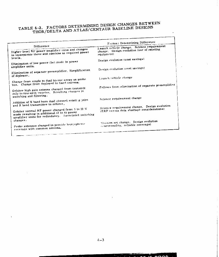
TABLE 6-2. FACTORS DETERMINING DESIGN CHANGES BETWEENTHOR/DELTA AND ATLAS/CENTAUR BASELINE DESIGNS
*
Difference Factor.] Dt, termLning Difference,
liighot • level RF power amplifier _mits and changes Launch v_,hic|e change, Science requLrementto incorporate these and combine to reqt_ired power chan_e. Design evolution (use of existinglevell, equipmentl
Elimination of low power {1_,) mode in power Design evolution (cost savingslamplifier units.
Elimination of sepa rate preamplifier. Simplificat Lon De si_,n evolution (co_t savin2 _)of diplexer.
Change from sin_.le to dual bi,:ono array on probe l.nunch vehicle chanRebus. Cban_e from deployed to fixed _.ntenna.
Orbiter high Rain antenna chanRed from transmit Follnws from elimination of separate preamplifieronly to trar, srrit receive. Resultin_ chan_es inswitching and filtering.
Addition of X band horn dual channel rotatlufl joint Science requirement chan_eand X band transmitter to orbiter.
Orbiter normal RF power changed from 5 to 10 W Science r_quirement change. Design evolutionmode resultmg in additional (2 to 4) power (ERP versus data shortage considerations}
amplifier units for redundancy. Associated switehin_chan_e s .
Probe antennas chanRed to provide hemispheric ,_,li:_._ion ._et chan2e, Design evolutioncox.erase with common antenna, i,-omrnonality, reliable coverage)
.............................................
..... II I [ ' ...............i
O0000002-TSA07
6. I DUAL FREQUENCY OCCULTATION IMPLEMENTATION TRADE
The principal trade in determining the Atlas/Centaur cornmunications
configuration for the orbiter was the selection of the implementation for adding
the X-band capability for the dual frequency occultation experiment. Configura-tion aspects of this trade are discussed in Volume 4 and attitude control con-
s_6crations are covered L: Volume 9 of this report. This discussion will focus
on the systems aspects of the selection. Subsystem design factors willbe dis-cussed in sections 6. Z and 6.3.
The orbiter must have the capability to perform a dual-frequency radio
occultation experiment during the initialEarth occultation season after arrival
at Venus_ The frequencies are S-band (th__spacecraft telemetry downlink) anc_
X-band (an rf system to be added specifically and only for the occultation ex-periment). Requirements for this experiment are:
1) The S- and X-band links must be capable of simultaneous operation.
Z) The two links must be compatible with DSN capabilities.
3) Each link must be receivable for atmospheric refractions of up to
I0 deg, but a capability up to Z0 deg is desired.
4) The period of occultation measurements will normally be limited to
the first 40 days in orbit but coverage for the entire season (YZ
days) is desired (3 dB more ERP ). However, later in the season,things are complicated by the eclipses that occur during the occulta-tions.
5) The frequency relationship of the S- and X-band downlinks must bethe precis ratio of 3/11 for both coherent and noncoherent S-bandcommunic_. ,n modes.
6) The signal level at the DSN receiver shall be -178 dBm or greaterfor both links.
7) The 64 m DSS antennas will be used for all occulta .on measure=ments.
t
The spacecraft ERr requirements to satisfy the above requirements are_ummarized in "Fable 6-3.
]t can be seen from Table 6-3 that the S-band corntnunications system
which has an on-boresight ERP of 63.5 dBm can naeet the most stringent re-
quirenlent_ 20 deg refractive angle, at the end of the occultation season (7Z
days). But, it must be steered in two dir_ensions to track the virtual earth_
since the first null occurs at about 15 deg. However, it can be used without
steerin_ at 10 ch.,._ off-boresi_ht wh(;re the _,_ain is tJOWll by only l0 dB to meetthe nominal requirement of a 10 clc_, refractive angle to 40 days into theoeco,_tati()n,_u&son.
(_- 4
...... ,. .... 00000002-TSA08
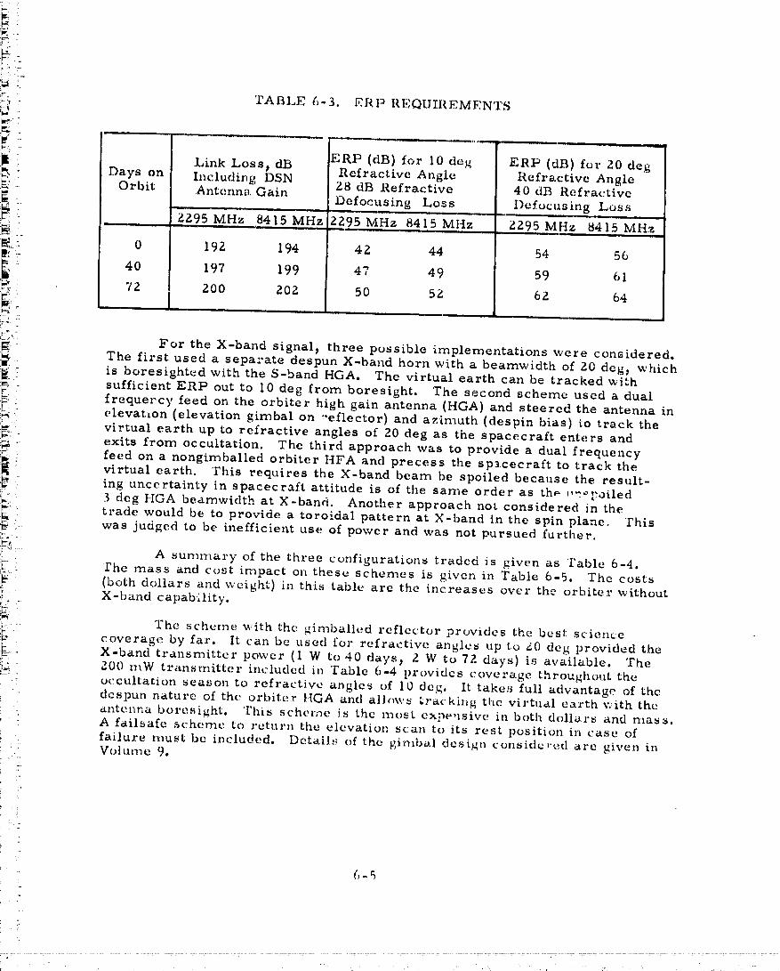
_ _' 7"
:,_- ' TABLE i,-3. ERP REQUII{EMFNTS
_ -
Link Loss_ dB ERP (dB) for I0 deg ERP (dB) for 20 deg
::_- Days on Including DSN Refractive Angle Refractive Angle_K"- Orbit Antenna Gain Z8 dB Refractive 40 ¢113 Refractive
. Defocusing Loss Defocusing LossJr;: :: , ZZ95 M.Hz 8415 MHz ZZ95 MHz 8415 Mttz ZZ95 MHz 8415 MHz
F4,_: 0 192. 194 4Z 44 54 56
::: 40 197 199 47 49 59 61..... 72 ZOO 20Z 50 5Z 62, 64
_ For the X-band signal_ three possible implementations were considered.
._, The first used a separate despun X-hand horn with a beamwidth of Z0 deg_ which
i_ _ is boresightedwith the S-band HGA. The virtual earth can be tracked with. sufficient ERP out to 10 deg from boresight. The second scheme used a dual
._-x. frequerey feed on the orbiter high gain antenna (HGA) and steered the antenna inIN elevatLon (elevation gimbal on ,'eflector) and azimuth (despin bias) to track the:_=: virtual earth up to refractive angles of Z0 deg as the spacecraft enters and
!_:.: exits from occultation. The third approach was to provide a dual frequency
:_ feed on a nongimballed orbiter HFA and precess the spacecraft to track thevirtual earth. This requires the X-band beam be spoiled because the result-_ .; ing uncertainty in spacecraft attitude is of the same order as th_ --,'Fotled!:_" 3 deg HGA beamwidth at X-band. Another approach not considered in the
:_ i trade would be to provide a toroidal pattern at X-band in the spin plane. This:... was judged to be inefficient use of power and was not pursued further.
"_NJ .....
:, A summary of the three configurations traded is given as Table 6-4.!'he mass and cost impact on these schemes is Liven in Table 6-5. The costs
_' _ (both dollars and weight) in this table are the increases over the orbiter without
,; X-band capability.[y -
2. The scheme %,ith the gimballed reflector provides the best science:L- coverage by far. It can be used for refractive angles tlp to g0 deg provided the
:_i_ X-band transmitter power (I W to 40 days_ Z W to 7Z days) is available. The
_ g00 mW transmitter included in Table 6-4 provides coverage throughout the, occultarion season to refractive angles of I0 deg. It takes full advantage of the
'- despun nature of the orbiter }{GA and allow_ _racking the virtual eal'th with the• antenna boresight. This scherne is the most expeusive in both dollars and ma_a.:_ A failsafe scheme to return the elevation scan to its rest position in case of
failure must be included. Details of the gimbal design considcr_;d are given inVol UFrle 9.
!:
5- 5
_ 7.
00000002 TSA09
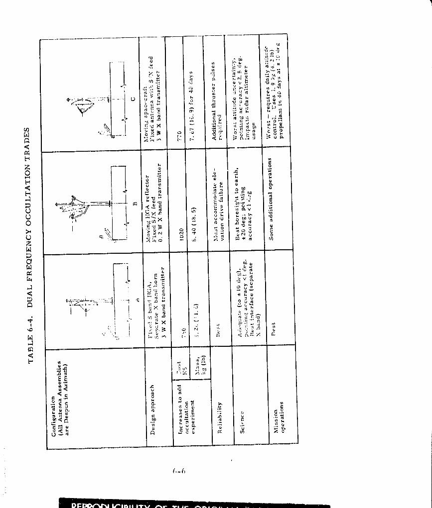
(,-(_
00000002-TSA10
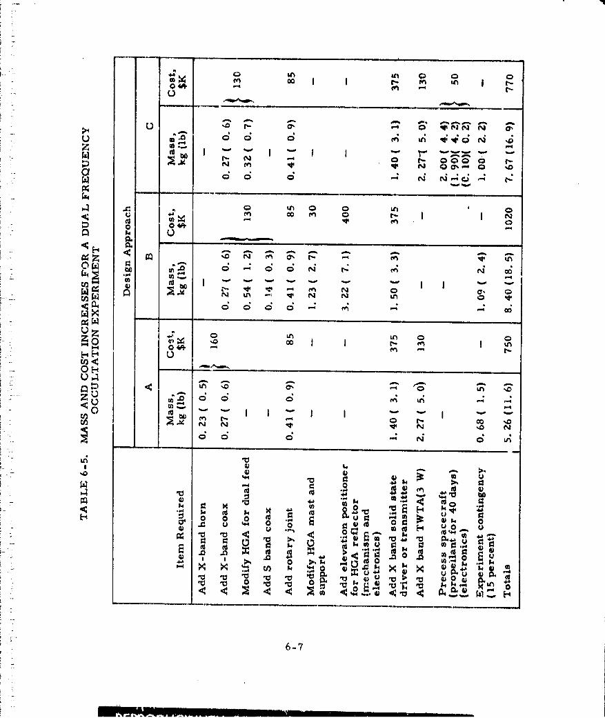
_i_"°
i _ '-J I_I ,'_ I"-
0 qI_NN N 0".
(_ _ 0 l',- 000 0 r'-.t • • • • • •
•,-, r-. I I N
_ _ ,Or.d _ -'-"
_ _ "=_ I "" "" *" "" "" I I "" "-.
i _ d c:;,5 d ,,-;r._ " " -- oo)
r_
.... 7v ....
O _ v I I "
i r
i - !,_ _ _ _ _ _: • _ m U I
_- )))o)_ ) "',,°.°.o°o.-_- _..'@ ._ M @
• _1 ,1:1 u "0 -u_ ;_ ._ _ _ _ _,_ "u'=., ,'_ _ X_ o I
.o
6-?! '
i
00000002-TSA11

A separate despun X band ht)rn prrJvides cove:rage to refractive anglesof l0 dog. However, the beam boresight is not pointed toward the virtual
earth but rather this scheme relies on tile antenna gain at ])tam edge.]%ecause of the nature of the S band beam this scheme cannot be exte.nded togreater refractive angles, in fact, because 10 ° corresponds to a point fardown on the gain slope (-10 dIt) of the S band antenna, the high rate of changeof gain with angle will make data reduction extremely difiicult. 2.8 W of Xband power is required. Table 6-4 refers to an _:xisting 3.3 W TWTA. Thecost in both mass and dollars i$ least of the three schemes and since the
spacecraft or anything on the spacecraft does not move during the occultation,it is the most reliable scheme.
Precession of the spacecraft to keep the antenna virtual earthoriented can be implemented. A discussion of this is given in Volume 9of this report. This scheme can operate to refractive angles of 20 deg.provided enough fuel is provided. Again, Table 6-4 refers to an existingTWTAwhich satisfies the ERP requirements. The costs are intermediatebetween the other schemes considered, bu*, this scheme presents problemsto other science because of the attitude uncertainties it introduces. I_ alsoincre.,ses the thruster pulses required and severely impacts mission opera-tions. Precession could be used in conjunction with_he separate despunX band horn discussed above to extend the refractive angle coverage of theseparate horn scheme.
Based on cost, weight, reliability, and operational simplicity theseparate despun X band horn is selected as the baseline implementation.However, it is recognized that the gimballed reflector implementationprovides a scientifically more attractive experiment at a relatively modestincrease in cost and takes maximum advantage of the features of the mech:..li-tally despun HGA. Combining the orbiter radar altimeter and the S/X bandoccultation experiment in a single dual frequen_'y HGA w'itl_ two-din'mnsionalsteering deserves further consideration when total costs can be evaluated byNASA.
To meet the requirements of this selected implementatio,_, the sub-systems must provide 49 dBm X band ERP at 10 deg. from the antenna bore-sight. This provides coverage to 10 deg. refractive angle to 40 days on orbit.The X band antenna should be separate, despun, boresightedwith the orbiterHGA, and have a beamwidth of 20 deg. and a gain of 17.5 dB (on boresight).The transmitted rf power at X band should be sufficient to meet the ERPrequirement stated previously.
6-8
00000002-TSA12
• 6.2 RADIO I"[_I';QUENCY SUBSYSTEM
P*'obe Bus
• The block diagratn ¢)f the t)*'c)l)e h,',s rf sub,-;yst(.m and its inlercannec-
tion with the ;tntcnna suhsystem is slmwn in Figure ()-l. Th(, l_asic lcqmlogyis essentially tim same, as thai ill the Thor/De.lta with a. pair _)f redtmdanttransponders, two power amplifiers, transmit filterinR, and rf switching
- and summing to {'f)llnf!et ;t, power amplifier output or the sunlrned OUtpllt Ot'
both amplific.r t:o th{_ four RI1|,cIII1D.S. The. main diffc_rcn¢'{,s are power ampla-t'ier mfil:s w:ith higher output levels and the el.imina_ion of separate rf pre..
amplification ahead of the transponder recc;iw,.r. There is no change in the:rf switching arr_, .uement.
Ad(,qualcmar_inin lh_, command link was available with the available
sensitivity of the Philco Ford Viking transponder that had been selected forthe baseline so that the preamplifier was unnecessary. The transponderincludes rf filtering in its input so that separate filtering in the diplexer alsois unnecessary. As a result, the diplexer is simplified to onl; _ circulatorfor coupling transmitter and receiver to an omni antenna.
A power aml_lifier unit composed of components currently underdevelopment on another space program at Hughes, H8-350, has beenincorporated in the baseline design. Each power amplifier unit includesa three stage driver module, a driver output isolator, and a hybrid coupledoutput stage utilizing two MSC 3005 transistors. An output isolator and dcregulator also is inchtded in the output stage module.
The amplifier provides 9 xv output with a gain of Z6.5 db. Althoughthe mass cf the powe.r amplifier unit is ncarly double that of the unit pro-posed for the Thor/Delta b0seline, the savings in development cost and thereduced devcloplr_enl risk in achieving the ,equired power output justifiesthe baselir, e ch;u_ _.
,\ :._mall increase iu otttllut powe. r is rc.quircd on the probe lms as a
result of._lightl._ longer RI?" cables in the "ktlas/Centaur spacecraft desiRn,Itowever, the. significantly hi_her power love.1 is provided to allow greateropcralio,_al fl_ xibi•lity and to permit use of idcnticai power amplifier unitsot_ the crbit(,r a:_d large probe systems where the full increase in power isneeded to meet increased data requirements. Table 6-6 lists the power,mass, and si>'e of the various components of the probe bus rf subsystern.
Orbitcr
'I'llc I,h_ck didgl'all_l t_( [}it., communication subsystem tor the orbiter
spac(,craf!, i:_ sh()x_n iT1 F',gurc 6-g.
r;:,,c,,pt r,_,. unique functions that r_quir(,, dit'fcrc_t eon_poncnts suchas an X baud t:van,,e_itlcr and ;t dual channel RF rota.ry joint, t.hc subsyste_n_-titi:,(:_ the ,_1,,t , },asia. ('(_nl)oncnts l.}l/It arc u:,c{] ot_ the prolm t,us. The
COml)Om,nt 1;tyout.s l(_r tilt, orl,it:_,r ;t,._(t prol)_, I)u:s also will })e made t:, l)e as
ClO.q_' |.0 idt'rtl.Jc/l[. /l:_ l)t)s:;il)l_,0
00000002-TSA13
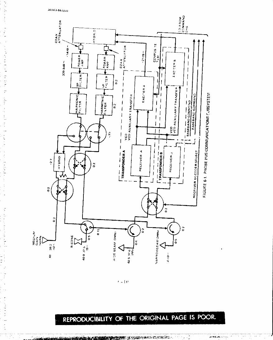
00000002-TSA14

: .........-I-: _
N
I-
-" C' _ ,._ _.] _ 0_, _ P"
• _ N .+ i if3
e_.' --_ ._ i I I I I .
I:l::l _"_ _ _o
i_ _ _
,r ,r _ 0
---_i
:7_I [
_-I-' ..: d ' c_ c-._ _ '
.... -T ....................................................
._ _+ _ ,r _. ¢,_ _ _ _ _. _ r,3 ..,_" +'_ 3o
.. - ...... _,
+ __ .
" _ " _ _ _' _ 7. _... ._ _ .., ,._.... :_; -, _+ i,_ :- / r" _ 2.,
(,-II
, l l I ......• rll
O0000002-TSB01

_,=17.
O0000002-TSB02
The changes from the Thor/Delta baseline, described in Section 5,
include the elimination of separate preamplifiers and simplification of thediplexer as in the case of the probe bus subsystem. The reduction in sensi-
tivity and redefined orbiter mission requirements results in a need to receive
as well as transmit through the high gain antenna. As a result the switching
arrangement on the despun portion of the subsystem is revised with a single
SPDT switch connecting the RF line to either the high gain or ornni antenna.
The notch filter is eliminated, since the uplink signal must pass through theswitched line. Sufficient isolation is provided by the switch to prevent inte1'-
ference between the two antenna patterns.
The power amplifier unit output level is increased to 9 w using the
same unit described for the probe bus. The high power mode, about I0 wat the antenna terminals, uses a pair of amplifier units operating in parallel.
System operation has been changed such that this is now the normal mode ofoperation instead of the single amplifier mode. As a consequence, it is
necessary to provide two additional power amplifier units to serve as
redundant units to the two in operation. All four amplifiers are driven
through hybrid circuits to allow independent selection of amplifier A or B
for operation with either C or D. Following the redundancy selection switch,
the signal paths are the same as in the Thor/Delta baseline, except for theelimination of a transfer switch between the two low power output lines.
In the new configuration, there are two amplifiers available to feed each ofthese lines, one of whi, 1_goes to the spinning omni and the other to the high
gain or despun omni. Thus, each output is fully redundantly driven and thetransfer switch is no longer necessary.
An X band transmitter, dual channel {S and X band) rotary joint and
a separate despun X band horn antenna have been added to the orbiter sub-
systems re."the dual frequency occultation experiment. The 3 W X band
transmitter shown in Figure 6-3 co.nsists of a solid-state driver and a space
qualified TWTA. The rotary joint is a concentric coaxial line design with
the X band signal being carried on the inner coaxial line. This results in
the least impact on the performance of the S band link with the loss increased
by only 0.1 d tS.
'Yal,h_6-7 summarizes the power, mass, and size of the components
in the orbiter space,Traft RF subsyst<'m.
L_c .P r(_be
Figure 6--1 _}lows a blo_k diagram Lsf thL_ l'f _/lbsy_tup.l for the largei)r_._bc. Fhc _ ,)nfi_4uration has b,,*en t'xtcnsivcl,: z'cvi_,cd from that dt, s¢'rib¢_dft_rth,,Tht)r/"Dul_a ba._:linc. As in the ta._c of the apa<t_¢ raf[ sub_.stt;n,s_ the
separate l'_,c_:iv_,, filtci' alxd prc, azllpltfier hay(, beetl clir_linatcd s in¢ c the inptzts_nsitivit, y _Jf t;h(, Vikin_ tra,sp(mch,_r provides actcq,_nlc margin for the, uplink.
The' [.ransnl}tt(,r portion is rt:vi.scd t_, pz'¢_vidc n¢.arJy _ dB high(_r outputlevel, rhia in_.l-¢,_.tse is (l_le p_'imarily Io an in¢ z'_asc Jz_ hlllI,clllla C,r)",'C2"¢i_¢_
((h,'cI ..a._,,.!d ga•,," i_), To at hicvc thi:-;; thrc,: _utp_t ,sta. g_' _:l_,,(h_lt_s of th(' i(le_)ti,'aJ
design as tb(' _;_,d_l,"4 i_1 !ht' st_dard 0 _.' p,,v,'t_r az_)lificr u,_it arc _,pcratcd
(,-13
O0000002-TSB03
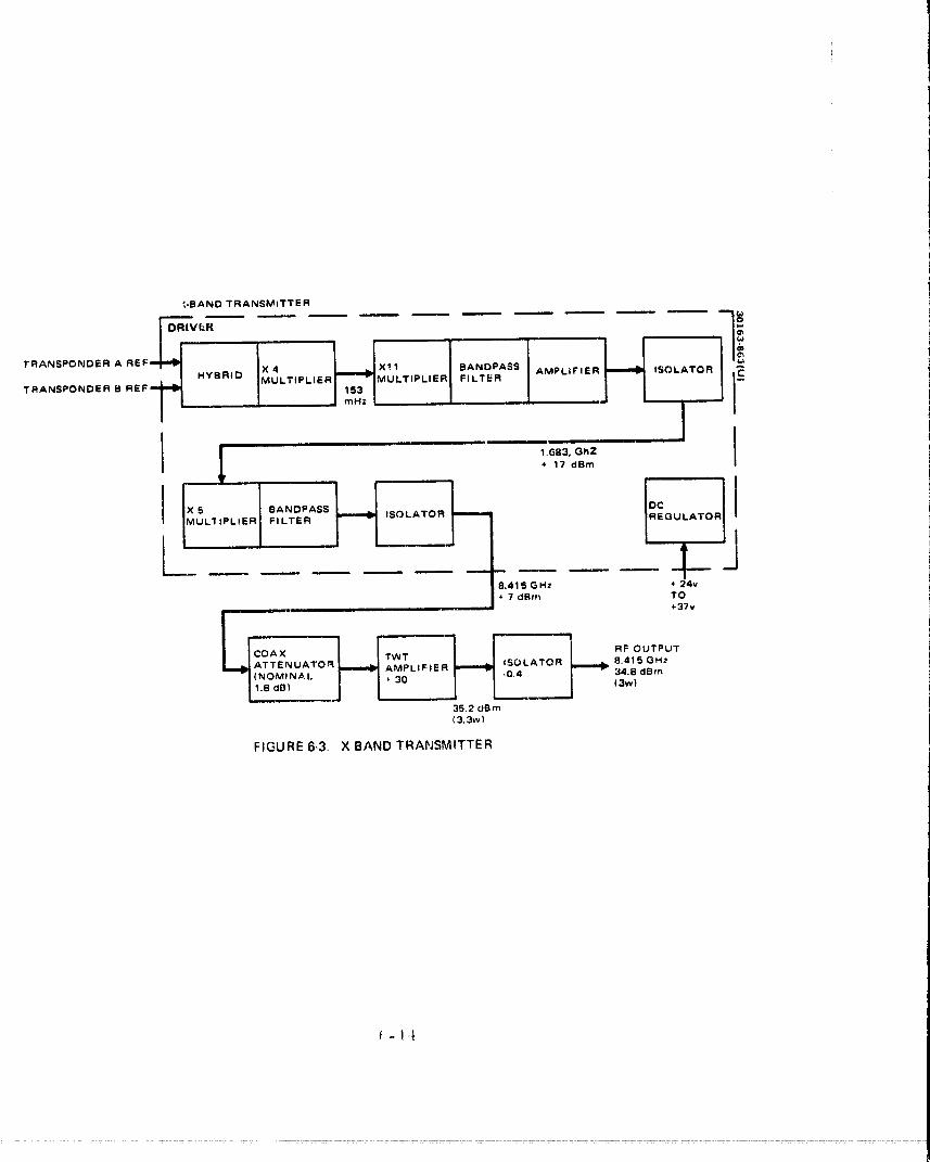
_-BAND TRANSMITTER
I 1.683, GhZ
+ 17 dBm
X 5 BANDPASS REGULATORJMULIIPLIER FILTER
l8.415 GHz * 24v• 7 dflm TO
+37v
ATTENUAI"O_ _ AMPLIFIER ISOLATOR 8,415GHz(NOMINAl,. _' 30 -0.4 34.8 dBm
1,8 clB) / (3w)
35.2 dBm
(3.3w}
FIGURE 6-3. X BAND TRANSMITTER
O0000002-TSB04
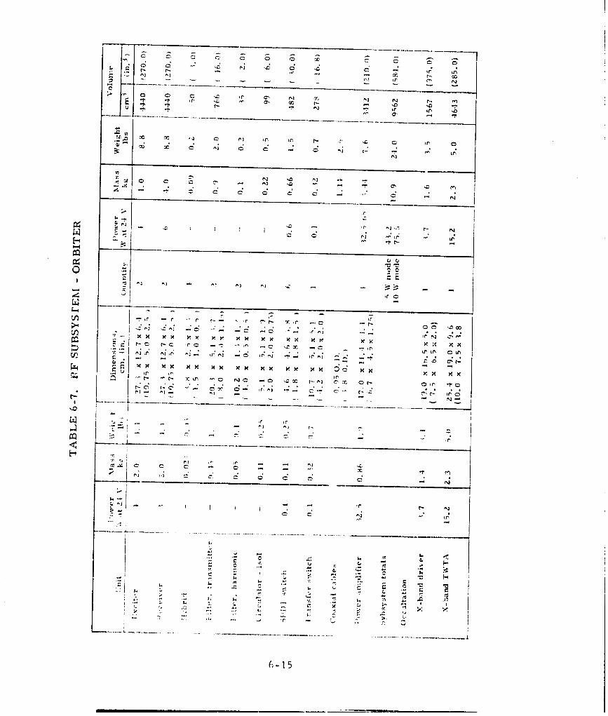
6- 1 5
I I i , , .... l,i.. - --,
O0000002-TSB05
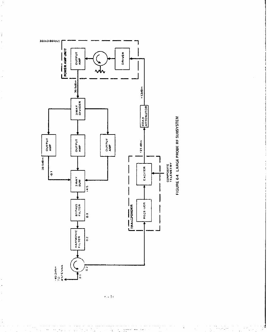
O0000002-TSB06
in paral.l.el. The modules are completely package units, since they are
separately mounted in their present application on the HS-350 satellite system.
They each include regulators and output isolators to provide stable operationunder possible adverse loading conditions during te_ting. The output ampli-
fiers are driven through a 3 way quarter-wave transmission line divider by acomplete power amplifier unit. The outputs of the amplifiers are recomhincdby another identical 3 way transmission line circuit operated in reverse toprovide the summing function. The summer and dividers are similar to spacequalified units that provide 16 and 6 way summing at UHF on the TACSAT andcommunications equipment (HS-318) subaystems.
Since common hardware is used_ a miniature coaxial attenuator is in-serted in the output line from the transponder to the input of the power am" If-tier unit. This compensates for the hybrid losses which are incurred on thespacecraft subsystems.
Table 6-8 lists the power_ maas_ and sizes of the components of the
large probe rf subsystem. The three modules of the power amplifier unit(driver_ isolator_ output amplifier) are listed separately to allow flexibility inthe layout of equipment within the unusual constraints of the probe package.However, they will be tested as a unit with the appropriate interconnectingcables.
Small Probe
Figure 6-5 shows the block diagram of the small probe rf subsystem.The configuration is the same as that for the Thor/Delta baselinc_ except forthe change in poxver amplifier. In the ne_ bascline_ the standard 9 W amplifierunit is used. As in the large probe_ there is flexibility in mounting the threemodules that comprise the unit. The power_ mass_ and size of all the com-ponents are listed in table 6-9.
6. 3 ANTENNA SUBSYSTEM DESCRIPTION
I'he antc_ma,_ on the orbiter_ probe bus_ and the large and small probeshave been _clc,.'t, ed and designed on the basi,_ of the gain and _overagc require-Fnunts st|tru_]_xrizt;d in [able 6-10.
Prob_, l_tl_ Alltenlla Subs\stc, tn
Four anLennas are provided on the })robe bus a_ shoxxn in Figure 6-0,File ilit(,r('<mncction (Jr the ant,,nna._ with the rf ,_ub_v_tcn_ is dt,'_cribed in
._¢:,¢tion t, I. The alltellrla,_ havc beetl ¢ hO_Cl', (;!1 the basis of C¢_lTiIllono.lity J.Ild
off-the-shelf availability t_,; louver the c_l and n_.<,t th(, pcrf()rn_ancc rcquirc-nlc_t,_. Th<, I,_._tlo_ _]i the anlcnna._ <_ the sl)_t,t r_ft _._ ._x(,'rnvd o v the, radia-
Lion patt,'m_ ,,,;hapc a,'_d l!le sl)_tt Ctl'aft strm t_irc t() avoid dcgra(lati_m of ¢ <)v_,r_:.cil_ the doxvn and _11)linl<._ durii_a all l)has,',-: of the n_.s._iun,
I_,_',-¢ ()tli_ et] i±!_(l _t ._l<_tl,.,¢t-, ,,n,, t)_tllidil'_'¢'li¢_ll_.*] _).l/tt, llila_ [(_¢ o.lt'tl ¢,I1
oplmsit¢_ _,.i,([.s t)f l}Ic ._l)<_,_ ¢.'< I'<)f'!_ _Art' _ _)1111¢'¢. it,(] t(_ ,%l'[)/.tl t_.t_' I'¢'_¢'iv'L'!', '_ i_,llt[
.........................." " O0000002-TSB07

O0000002-TSB08

O0000002-TSB09

O
(El{LEVEL) 0_
Q, _t --
OUTPUT COA XIAL g ,_(CITER ORCIL LATOR
3ii.4ANTENNAdBm AMPI.IFIER /,T TENT UA TO R _E '(C_ E R_ i TABLEI COMPOSITE/ POWER AMPLIFIER UNITI,,,=,=_ ..,m..,_., _ .,--.. -.- _ _,.,i " TELEMETRY
FIGURE 6-5. SMALL PROBE RF SUBSYSTEM
m
I t Conical LogSpiral Antenna dD
_I............._L_L
...... Medium GainConical Horn
{ _ Bicones
e--_-___ Broad CoverageSlotted Cone (Surveyor)
• / Omni Antenna
FIGLIRE 6-6. PROBE BUSA',_'rENNASUBASSEMBLY
t',-? 0
: ' O0000002-TSBIO

O0000002-TSB11

(,_22
O0000002-TSB12

transmitters so as to provide nearly spherical coverage at all times. A biconeantenna assembly provides directional co,_eragt: in the spin plane with a _ain
of 6. OdB on bean_ axis. Tile torodial pattern shape makes it annucu,_0,vy tod_spin t.hc antenna. A mediate gain horn radiator is used during prob__ busentry when lhe earth liltt: and the spacecraft spill axiu art: coincident. Thehorn radi_tt, v provid*.'s a gain of 18 dB with a Z0 deg half-power bcan_,_idttt,The two t_mnidirc,:tinnal antennas and the horn are not changed from t|m Their/
Delta baseline. The bicone design ia revised tc incre.ase tim gaill by _$ dB.The charactt.'ri,_tics tat7 tht_ probe bu_ antennas arc _unm,ariaed in Table 6-11.
1'he biconu ant_m_a a_sembly is based on an existing de_ign_ shown inFigurta 6-7. Two identical bit:ones are stacked and arraye(t to achieve a peakgain of b dBi in the spin plane. The maximum allowable dhncnsions of thebiconc assc, n_bly envelope bast.'d on currently available spacecraft tipoff rattanand on a 4. 3 cm (worst case) clearant:c between the antenna and the adapter
during separation ar_ given in Figure 6-8. A single bicone cannot provide the6. 0 dBi gain within the constraints of this envelope (Figure 6-9) btacause phaseerrors limit the gain of a large single bicone, Thus_ two stacked bit:oneswere selected.
Each bicone consists of a short circular wavtaguide feedline that ends
in a coaxial to waveguide transition at one end and a c:lindrical feed cavity
excited in the TM01 mode at the other. Eight equally sp_.ced crossed slotsare machiner' into the outer wall of the feed cavity. The slots setup the
orthogonal modes_ TE 0 and 'rEM in the flared radiation region. The flare1angle of the bicone and the characteristics of the crossed slots are t-se¢l tobring the two modal fields into time quadrature and equal amplitude to provide
right-hand circular polarization.
Orbiter Antenna Assembly
The antenna assembly on tt_e orbiter spacecraft, i;'igure t,-10, includesthe high gain parabt_lic rcflector_ the X band horn for the science experiment_and tx_t) xvidc antic cove rage, low gain antennas. The latter txvo are. identicalin design to those ust.:d on the prt_be bus and arc unt:hanged from the Thor/Delta baueline. The high gain antenna is mechanically despun so that the mainbeam is pointed toward earth. 'rhc design of the high gain antenna also is notchanged from the Thor/Delta design, the X band nacdium gain antenna also innot changed from the Thor/Delta design. The X band medium gain antennahas bt.'en added to accommodate the occultist ion experiment, It is a conicalhorn dt:_igned to operate at a frequency of _¢,415 Gila, l'he nonai_lal gain and3 dI3 beamxvidth al't_ 17. 5 dB and g0 deg_ re'_pc, ttively, The X-band antcm_aas,_end)ly consist_ of the conical horn aperture_ polariser andw,tveguidc
tran._former. All t:omptmcntn are I)asect on tile designs used in the t,,anufac-tare of the global co,..t;ra.,.e conit'al horns for the Intel,_at IV pro!-ram. Thosehorns wcr_: operated in the frequen_:y band_ of 4 attd 0 GHa. rhe horn aper-ture tlirtl_,'_SiOll of 12, 7 {ll_ iu govt;rned [)x' tht, gi±ill slid beanlx_idth rc(luirt;-
month, The overall h.'l)Rth of 21, ¢0 t:tt,, is ct)ntrt)lh.'d by tilt: h_n!-th of the hornitself, tilt: pola,'izt:r and the _avt:_uidc trotnSfol'_:t..r, 'file l.)olarlzt:r i_ _).._i)_-plititad ver.,,it_l! t)f tht,. l nh.'lnat IV dc. sit_ll) b(:t _ttt.'it_ of tht.. reduced bandv, idth,'ectuir,,'_,_,nt _f th,; X-bend ptdarizt_r,
_,-.2 ¢
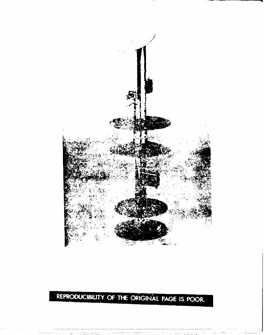
........ "'" ,;" . "_ ,'" _L ,i..." ," _ , ,.* ".................................................: ::_. :Z _ : : ....... _ q -7[_r.................... --[[' . ..... ! : .....
O0000002-TSB14
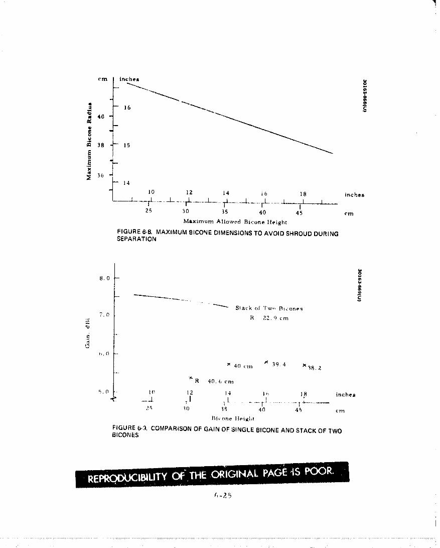
cm inches
.-...._ -
- 16'_ 40 -
._.m 38 - 15
E
_ 14 10 lZ 14 i6 18 inches__L___rL......._L_.... �......_.__TL......._i........I_L......i....r.L__25 30 35 40 45 cm
Maximum Allowed Bicone Height
FIGURE 6-8. MAXIMUM BICONE DIMENSIONS TO AVOID SHROUD DURINGSEPARATION
O
8.0 -Or,
Stack of Tw,, Bicones
7.0 R 22.9 cm
"D
;2
t_.0 --
x 39 4 x38.240 (:I1"_
_"R 40. (, crn
9.0 '-- I_ 12 14 I,_ 18 inches_.1 TI 11...............T1 ............Ia............
2r_ t0 _5 40 45 cm
t_ic _ane lleight
FIGURE 6,3. COMPARISON OF GAIN OF SINGLE BICONE AND STACK OF TWOBICONES
(,-?. 5
.... .... 00000002 TSC01
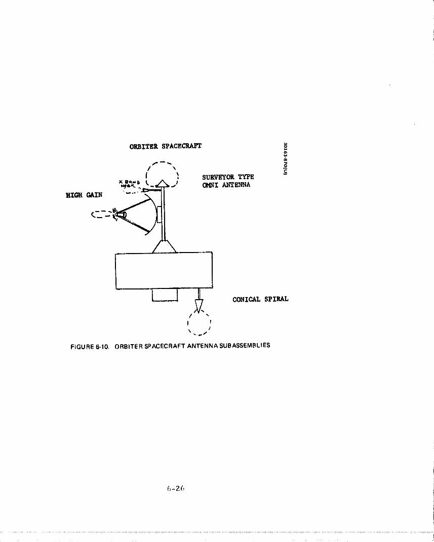
ORBITER SPACECRAFT
, SURVEYOR TYPE -
-._-_._ _-J OMNI ANTENNA
HIGH GAIN
_ ,/\
,J
/ ",t i
FIGURE 6-10. ORBITER SPACECRAFT ANTENNA SUBASSEMBLIES
6-26
00000002-TSC02
Overall characteristics of the orbiter antennas are summarized in'Fable 6- I Z.
Probe Antennas
The antennas on the large and small probes are required to provide
hemispherical covex_ge with a gain of 0 dBi in the horizontal probe plane andpeak gain at b0 to 6_= deg off axis. Several candidate antennas that have beenconsidered for the ,atlas/Centaur baseline are t_xbulated in Table 6-13.
/% candidate is the slotted cone radiato_" which would be identical tothe omnidirectional antenna used on the orbiter spacecraft of the probe bus.
However_ its gain is several dB below isotropic at 90 deg off axis. Other-wise it would be well suited for the application_ since it is lightweight and
small. The conical log spiral can provide coverage in the horizon planesimilar to the curved turnstile radiator. However, it has to extend higher
above the probe shell. /%lso, it is heavier by a factor of two. It is not con-sidered the prime candidate. Even though it is the same type of antenna asused in the omnidirectional antenna assembly on the orbiter spacecraft and
the probe bus_ the antenna for the probe would have to be designed usingdifferent parameters such as a different spiral rate.
The selected baseline for both probes is the curved turnstile which is
shown in Figure 6-11. It is similar to the slotted cone radiator in that bothuse a cross dipole. The design is that of a crossed dipole radiator. By
proper phasing and downward bending of the orthogonal d_pole arms_ thenormal dipole pattern can be perturbed sufficiently to provide nominally0 dBi at 90 deg off axis and maximum gain at an ule_ of 00 to 65 deg off axis.
The circularly polarized radiation can be achieved b', feeding the two crossed
dipoles in equal anaplitude and 90 deg out of phase by using a quadrature
hybrid. Or the hybrid can be omitted and the circular polarization achieved
by having the two dipoles unequal length but keeping the length-versus-diameter ratios of the two dipole arn]s equal. The quadrature hybrid feed is
preferred_ because several design iterations would be expected w[th theunequal length dipo',cs to achieve the desired r,_sult. A loss of 0. I to 0.2 dB
is expected due to the quadrature hybrid.
(;-27
00000002-TSC03

6-28
00000002-TSC04
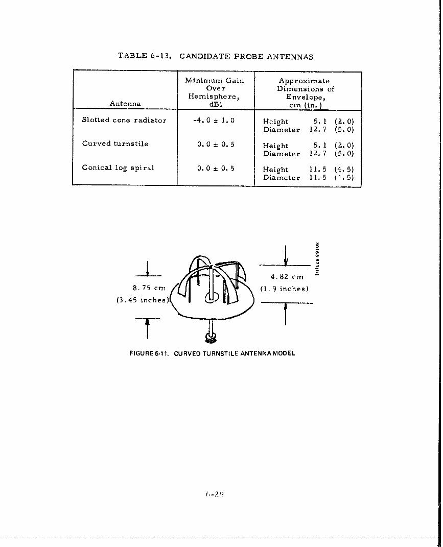
TABLE 6-13. CANDIDATE PROBE ANTENNAS
l .....
Minimum Gain A pp roximateOver Dimensions of
Hemis phe re, EnvelopeAntenna dBi cm (in.)
Slotted cone radiator -4.0 ± 1.0 Height 5. 1 (2.0)Diameter 12.7 (5.0)
Curved turnstile 0.0 + 0.5 Height 5. 1 (2.0)Diameter 12.7 (5.0)
Conical log spiral 0.0 + 0.5 Height 11.5 (4. 5)Diameter 11.5 (4. 5)
•-- 4.82 ¢m -
8.75 crn (1.9 inches}
s)(3.45 inche
!
FIGURE 6-11. CURVED TURNSTILE ANTENNA MODEL
00000002-TSC05