r35 gt-r gt1000 full turbine kit installation manual · published in june, 2012 by hks co., ltd....
TRANSCRIPT

- 24 -
R35 GT-R GT1000 FULL TURBINE KIT
INSTALLATION MANUAL
Installation must be done by a professional. Read this manual prior to the installation.
Always have access to this manual as well as a factory service manual.
Make sure the vehicle is applicable to this kit.
REVISION OF MANUAL
Rev. Number Date Manual Number Details
3-3.01 2012/6 E04211-N49020-00 1st Edition
Published in June, 2012 by HKS Co., Ltd. (Unauthorized reproduction is strictly prohibited.)
NAME OF PRODUCT R35 GT-R GT1000 FULL TURBINE KIT GT800 !GT1000 UPGRADE KIT
PART NUMBER 11003-AN013 (GT1000 FULL TURBINE KIT)
14020-AN006 (GT800 !GT1000 UPGRADE KIT)
APPLICATION NISSAN GT-R (R35)
ENGINE VR38DETT
YEAR 2007/12 -
REMARKS NOTE ! The engine must be removed in order to install this kit. ! This kit does not include the fuel parts and engine management parts. ! Upgrading the engine internals and drive trains are necessary to use this kit. ! The boost pressure setting for the provided Wastegates is approximately 90
to 100 kPa. ! It is recommended to use with HKS Racing Suction Kit. ! GT1000 Upgrade Kit is to upgrade the GT800 Full Turbine Kit to GT1000.
This kit was developed exclusively for off-road race use only. HKS will not be responsible for engine and/or transmission damage caused by the use of this kit. This kit must be used without the catalytic converters. Because of this, the vehicle cannot be driven on any public roads or highways since it may not meet pollution laws and/or safety regulations. Any vehicle with this kit installed may void the factory manufacturer’s warranty.

- 25 -
INDEX
NOTICE ATTENTION 1
PARTS LIST 2
1. REMOVAL OF FACTORY PARTS 7
2. INSTALLATION OF KIT PARTS 7
3. CONFIRMATION AFTER INSTALLATION 22
NOTICEThis manual assumes that you have and know how to use the tools and equipment necessary to safely perform service operations on your vehicle. This manual assumes that you are familiar with typical automotive systems and basic service and repair procedures. Do not attempt to carry out the operations shown in this manual unless these assumptions are correct. Always have access to a factory service manual. To avoid injury, follow the safety precautions contained in the factory service manual.
ATTENTIONThis manual indicates items you need to pay attention to in order to install this product safely and lists precautions to avoid any possible damage and/or accidents. This product is an automobile part. Do not use for any other purposes. HKS will not be responsible for any damage caused by incorrect installation and/or use, or use after modification and/or dismantling of this product. This product was designed for installation on specific factory vehicles. The specifications of this product are subject to change without notice. The instructions are subject to change without notice. Make sure to refer to the most recent instructions.

- 26 -
PARTS LIST NO. DESCRIPTION QT
(11003-AN013)
QT
(14020-AN006)
IMAGE REMARKS
1 Exhaust Manifold LH 1 -
2 Exhaust Manifold RH 1 -
3 Turbocharger LH 1 1
4 Turbocharger RH 1 1
5 Wastegate 2 -
50mm
6 Front Pipe LH 1 1
7 Front Pipe RH 1 1
8 Suction Pipe LH 1 -
9 Suction Pipe RH 1 -
10 Suction Pipe 2 2
11 Chamber Pipe No.1 2 2
12 Chamber Pipe No.2 LH 1 1
13 Chamber Pipe No.2 RH 1 1
14 Oil Inlet Pipe LH 1 -
15 Oil Inlet Pipe RH 1 -
16 Oil Out Adapter 2 -
17 Water Pipe IN LH 1 -
18 Water Pipe IN RH 1 -
19 Water Pipe OUT LH 1 -
20 Water Pipe OUT RH 1 -

- 27 -
PARTS LIST NO. DESCRIPTION QT
(11003-AN013)
QT
(14020-AN006)
IMAGE REMARKS
21 Turbocharger Bracket LH 1 1
22 Turbocharger Bracket RH 1 1
23 Chamber Pipe Bracket LH 1 1
24 Chamber Pipe Bracket RH 1 1
25 Engine Mount 1 1
26 Exhaust Manifold Gasket 2 -
27 Turbocharger Gasket 2 2
Inlet
28 Turbocharger Gasket 2 2
Outlet
29 Front Pipe Gasket 2 2
30 Oil Out Gasket 4 4
31 Compressor Out Gasket 2 2
32 Silicone Hose 2 -
70mm L70
33 Silicone Hose 2 -
70mm L55
34 Silicone Hose 2 2
60mm L70
35 Hose 1 -
10mm L1000
36 Hose 1 1
10mm L600
37 Hose 1 -
8mm L200
38 Hose 1 -
6mm L4000
39 Corrugated Tube 1 1 15mm L500
40 Thermo Tube 1 - 17mm L500

- 28 -
PARTS LIST NO. DESCRIPTION QT
(11003-AN013)
QT
(14020-AN006)
IMAGE REMARKS
41 Banjo Bolt 2 -
12mm Orifice
42 Banjo Bolt 4 -
14mm
43 Plug 4 4
M14
44 Copper Washer 12 12
12mm
45 Copper Washer 12 12
14mm
46 G-cup Ring 2 -
90.8mm
47 G-cup Ring 2 -
58.4mm
48 Hose Clamp 8 -
#48 Bead Type
49 Hose Clamp 4 4
#40 Bead Type
50 Thermo Insulation Sheet 3 -
300×300
51 T-fitting 1 -
8mm
52 T-fitting 3 -
6mm
53 Hose Fitting 2 -
10mm
54 Hose Fitting 3 -
6mm
55 Hose Fitting 2 -
6mm L-shape
56 Elbow 2 -
PT1/8
57 Power Steering Union 1 1
58 O-ring 1 1
59 Fitting 1 1
90°
60 Joint Pipe 1 1
10mm

- 29 -
PARTS LIST NO. DESCRIPTION QT
(11003-AN013)
QT
(14020-AN006)
IMAGE REMARKS
61 Air Cleaner Filter 2 2
62 Hose Clamp 2 2
10mm (155)
63 Hose Clamp 4 -
10mm (138)
64 Hose Clamp 5 -
8mm
65 Hose Clamp 14 -
6mm
66 Spacer 4 4
4mm t1.5
67 Spacer 1 - 6mm-12mm L10
68 Plug 2 -
PT1/8
69 Tie Wrap (M) 10 10
70 Bolt 4 4
M4 L10
71 Cap Bolt 3 3
M10 L30 Low head
72 Cap Bolt 4 - M6 L12
(Small Dia.)
73 Bolt 6 - M6 L10
74 Bolt 1 - M6 L25
75 Bolt 2 2 M8 L15
76 Bolt 3 - M8 L20
77 Bolt 2 2 M8 L25
81 Bolt 2 2 M8 L30
79 Bolt 4 - M10 L40
80 Bolt 2 - M10 L25
- 30 -
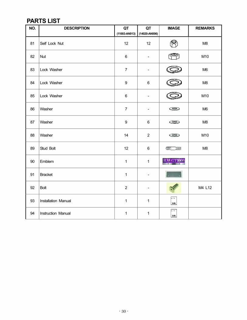
PARTS LIST NO. DESCRIPTION QT
(11003-AN013)
QT
(14020-AN006)
IMAGE REMARKS
81 Self Lock Nut 12 12
M8
82 Nut 6 -
M10
83 Lock Washer 7 -
M6
84 Lock Washer 9 6
M8
85 Lock Washer 6 -
M10
86 Washer 7 - M6
87 Washer 9 6 M8
88 Washer 14 2 M10
89 Stud Bolt 12 6 M8
90 Emblem 1 1
91 Bracket 1 -
92 Bolt 2 -
M4 L12
93 Installation Manual 1 1
94 Instruction Manual 1 1

- 31 -
1. REMOVAL OF FACTORY PARTSRemove the exhaust system, engine, and turbochargers referring to the factory service manual.
NOTE Keep all removed parts until installation process is completed. Some parts will be reused.
2. INSTALLATION OF KIT PARTS
2-1. Relocation of Power Steering Line (Only for LHD)
Disconnect the power steering pipe and pipe clamp as shown in Diagram 2-1-1 and 2-1-2.
Install the Joint Pipe to the pipe clamp. Reinstall the pipe clamp to the vehicle. (Dia.2-1-3, 2-1-5)
Install the O-ring to the Power Steering Union. Install the Power Steering Union to the vehicle. (Dia. 2-1-4,2-1-5
Dia.2-1-1
Disconnect
Dia.2-1-2
Pipe Clamp
Dia.2-1-3
Dia.2-1-4Dia.2-1-5

- 32 -
Install the 90 Fitting to the Power Steering Union.
(Dia. 2-1-6)
Cut the 10mm Hose L=600 to approximately 500mm.
Cut the Corrugated Tube to approximately 430mm.
Cover the cut 10mm Hose with the cut Corrugated
Tube. (Dia. 2-1-6, 2-1-7)
Connect the 10mm Hose with the Corrugated Tube to
the 90 Fitting and factory power steering pipe.
Secure them using the 10mm (155) Hose Clamp.
Make sure to secure the hose using the Tie Wrap(s) so
it does not come in contact with the drive shaft and/or
any other parts of the vehicle. (Dia.2-1-6, 2-1-7)
2-2. Installation of Engine Mount(1) Replace the factory engine mount with the provided
Engine Mount using the following provided parts. (Dia.
2-2-1)
Cap Bolt M10 L=30 x 3
10mm Washer x 2
2-3. Installation of Exhaust Manifold
Install the Stud Bolts to the Exhaust Manifold LH and RH.
(Dia.2-3-1)
Stud Bolt M8 x 6
Dia.2-3-1
Dia.2-1-6
Dia.2-1-7
Dia.2-2-1
Cap Bolt & 10mm Washer
Cap Bolt

- 33 -
Install the Exhaust Manifold LH and RH using the
following provided parts. (Dia.2-3-2)
Exhaust Manifold Gasket x 2
Factory Nut x 12 (Reuse)
Modify the factory heat insulator so it does not come in
contact with the Exhaust Manifold when installing both
parts. (Dia. 2-1-3, 2-1-4)
NOTE
The modified heat insulator will be installed later.
Dia.2-3-2
Dia.2-3-3
Dia.2-3-4

- 34 -
2-4. Installation of Turbocharger
Install the Stud Bolt and Oil Outlet Adapter to the
Turbocharger LH & RH using the following provided parts.
(Dia. 2-4-1, 2-4-2)
Oil Out Gasket x 2
Oil Out Adapter x 2
M6 Cap Bolt x 4
M8 Stud Bolt x 6
Install the Plug to the position circled in Diagram 2-4-3 and
2-4-4 to the Turbocharger LH and RH using the following
provided parts. (Dia.2-4-3, 2-4-4, 2-4-5)
Plug M14 x 4
Copper Washer 14mm x 4
Tightening Torque: 35±2N m
Install the Hose Fitting 6mm to the Compressor Housing LH.
(Dia. 2-4-6)
6mm Hose Fitting x 1
NOTE
Wrap the threaded portion with Teflon tape.
Dia.2-4-6
Dia.2-4-1
Dia.2-4-2
Dia.2-4-3
LH
Dia.2-4-5
Dia.2-4-4
RH

- 35 -
Temporarily install the turbochargers to the exhaust
manifolds. Adjust the angle of the center housing and
compressor housing. (Dia. 2-4-7, 2-4-8)
NOTE
Adjust the positions of the Chamber Pipe, Oil Pipe,
and Water Pipe here so installation of these pipes will
be easier.
Make sure there is sufficient clearance between the
pipes and the vehicle’s body. Adjust the pipe
positions if necessary.
If it is necessary to change the installation angle of
the turbocharger(s), follow the procedure (5) and (6) to
change the angle.
Remove the Turbocharger and install the cup ring as follows:
(Dia. 2-4-9, 2-4-10)
1. Tighten to 16 ±1N m.
2. Lightly hit both sides of the cup ring with a brass bar.
3. Tighten to 16 ±1N m.
4. Lightly hit both sides of the cup ring.
5. Tighten to 16 ±1N m.
Tighten the bolts on the compressor housing to 13±1N m.
There are 6 bolts on each side of the compressor housing.
(Dia. 2-4-11)
Dia.2-4-7
Dia.2-4-9
Dia.2-4-10
No Contact!
Dia.2-4-8
Dia.2-4-11

- 36 -
Install the Turbocharger LH and RH to each Exhaust
Manifold using the following provided parts. (Dia.2-4-12,
2-4-13
Turbocharger Gasket (Inlet) x 2
Self Lock Nut M8 x 6
(9) Install the Turbocharger Bracket LH and RH using the
following provided parts. (Dia.2-4-12, 2-4-13
Bolt M8 L=20 x 2
Washer M8 x 2
Lock Washer x 2
2-5. Installation of Oil Pipe
NOTE
Reuse the factory banjo bolt on the engine block side.
Make sure to use a correct bolt for water and oil line.
The bolt with smaller center hole diameter.
Install the Oil Inlet Pipe LH using the following provided parts
and removed factory part. (Dia.2-5-3)
Banjo Bolt M12 x 1
Copper Washer x 4
Factory Banjo Bolt M12 x 1 (Reuse)
NOTE
Blow air to the pipe before installation to prevent a foreign
object from entering into the pipe.
Dia.2-4-12
Dia.2-4-13Bracket
Dia.2-5-1
RHLH
Water Oil
Dia. 2-5-2
Dia.2-5-3
Reuse
Bracket

- 37 -
Install the Oil Inlet Pipe RH using the following provided parts
and removed factory part. (Dia.2-5-4)
Banjo Bolt M12 x 1
Copper Washer x 4
Factory Banjo Bolt M12 x 1 (Reuse)
NOTE
Blow air to the pipe before installation to prevent a foreign
object from entering into the pipe.
Reinstall the factory oil out pipe using the following provided
parts. (Dia.2-5-5, 2-5-6)
Oil Out Gasket x 2
Factory Bolt M6 L=12 x 4 (Reuse)
NOTE
Blow air to the pipe before installation to prevent a foreign
object from entering into the pipe.
Bent the factory oil pipe so it does not come in contact with
the drive shaft. (Dia.2-5-6)
2-6 Installation of Wastegate
Install the Hose Fitting and Plug to the Wastegate. (Dia.2-6-1)
6mm Hose Fitting x 2
6mm L-shaped Hose Fitting x 2
PT 1/8 Plug x 2
NOTE
Wrap the threaded portion with Teflon tape.
Dia.2-6-1
RHLH
PT1/8 Plug
Dia.2-5-5
LH
Dia.2-5-6
RH
Dia.2-5-4
RH
Bent here

- 38 -
(3) Adjust the positions of the Wastegate’s upper case. (Dia.
2-6-2)
Make sure the Wastegates function properly after installation.
(4) Install the Wastegates to the Exhaust Manifolds using the following provided pars. (Diagram 2-6-3)
G-Cup Ring 90.8mm x 2
NOTE
Temporarily install the Front Pipe to adjust the angle of the pipes.
2-7 Modification of Factory Water Pipe
Modify the factory water pipe so it does not come in contact with
the Wastegate. (Diagram 2-7-1 to 2-7-4)
(1) Cut the factory water pipe as shown in Diagram 2-7-1.
(2) Drill a 7mm hole in the bracket as shown in Diagram 2-7-2.
Caution
When adjusting the upper case, use the SST or proper tools. If the proper tools are not used, the spring may come out and cause an injury.
RH: 30°
Dia.2-6-2
LH: 45°
Dia.2-6-3
Dia.2-7-2
7
7
Dia.2-7-1
Cut off

- 39 -
(3) Insert the provided Spacer between the modified bracket and the engine. Weld the factory water pipe (previously cut in 2-7-1) and install the pipe using the following provided parts. Make sure the pipe does not come in contact with the Wastegate, (Diagram 2-7-3)
Spacer 6mm-12mm t=10 x 1Bolt M6 L=25 x 1Lock Washer M6 x 1Washer M6 x 1
NOTE
If the cut pipes are connected with a joint hose, make sure
the pipes are secure to avoid leaks.
(4) Bent the 8mm pipe so it does not come in contact with the
13mm pipe. (Dia.2-7-4)
2-6 Installation of Turbocharger Water Lines
NOTE
Reuse the factory 12mm banjo bolts on the engine side.
Make sure to use the correct bolts on each water line.
Before installation, blow off any dust and/or debris inside the pipes with an air gun. Make sure no foreign objects enter the Turbocharger Assembly through the pipes.
(1) Install the Water Pipe IN LH using the following provided
parts. (Dia.2-8-2)
Banjo Bolt 14mm x 1
Copper Washer 14mm x 2
Factory Banjo Bolt 12mm x 1 (Reuse)
Copper Washer 12mm x 2
Dia.2-7-4
Dia.2-8-1
Dia.2-8-2
Reuse
Spacer
Dia.2-7-3
Weld here
Need adequate clearance

- 40 -
(2) Modify the factory heat shield so it does not come in contact
with the Water Pipe Out LH. Install the modified heat
shield using the following provided parts. (Dia.2-8-3)
Bolt M6 L=10 x 3
Washer M6 x 3
Lock Washer M6 x 3
(3) Install the Water Pipe OUT LH using the following provided
parts. (Dia.2-8-3)
Banjo Bolt 14mm x 1
Copper Washer 14mm x 2
(4) Install the Water Inlet IN RH using the following provided
parts. (Dia.2-8-4)
Banjo Bolt 14mm x 1
Copper Washer 14mm x 2
Factory Banjo Bolt 12mm x 1 (Reuse)
Copper Washer 12mm x 2
(5) Install the Water Pipe OUT RH using the following provided
parts. (Dia.2-8-5)
Banjo Bolt 14mm x 1
Copper Washer 14mm x 2
Bolt M8 L=20 x 1
Washer M8 x 1
Lock Washer M8 x 1
(6) Modify the factory heat shied on the right side so it does not
come in contact with the compressor housing. Install the
modified heat shield using the following provided parts.
(Dia.2-8-6)
Bolt M6 L=10 x 3
Washer M6 x 3
Lock Washer M6 x 3
Dia.2-8-5
Dia.2-8-4
Reuse
Dia.2-8-3
Dia.2-8-6
Modification required
Modification required

- 41 -
(7) Modify the factory hose as shown in Diagram 2-8-7.
Install the modified hose to the factory water pipe.
(8) Route the water line as shown in Diagram 2-8-8 and 2-8-9
using the following the provided parts.
T-fitting 8mm x 1
Hose Clamp 8mm x 4
Hose 8mm (Cut to 40mm in length)
2-9 Installation of Front Pipe
Install the factory A/F sensor and O2 sensor to both sides’
Front Pipe; then install the pipes to each Turbocharger
using the following provided parts. (Dia. 2-9-1)
Turbocharger Gasket (Outlet) x 2
Self Lock Nut x 6
G-cup Ring 58.4mm x 2
Dia.2-8-9
Dia.2-9-1
Dia.2-8-7
Cut this part to 15mm
Dia.2-8-8
T-fitting 8mm
Hose 8mm (40mm)

- 42 -
Install the Front Pipe Bracket using the following provide
parts. (Dia.2-9-2)
Bolt M10 L=25 x 2
Nut M10 x 2
Lock Washer x 2
Washer M10 x 4
NOTE
Install the bracket in the opposite direction of the factory catalytic converters. Install the center pipe using the following provided parts.
Front Pipe Gasket x 2 Bolt M10 L=40 x 4 Nut M10 x 4 Lock Washer M10 x 4 Washer M10 x 8
2-10 Installation of Chamber Pipe
Install the Camber Pipe No.1 and No.2 using the following
provided parts. (Dia.2-10-1, 2-10-2, 2-10-3)
Compressor Out Gasket x 1
Bolt M8 L=25 x 1
Bolt M8 L=30 x 1
Lock Washer M8 x 2
Washer M8 x 2
Silicone Hose 60mm L=70 x 1
Hose Clamp #40 x 2
Install the Chamber Pipe Bracket LH using the following
provided parts. (Dia.2-10-3)
Bolt M8 L=15 x 1
Lock Washer M8 x 1
Washer M8 x 1
NOTE
Make sure the Chamber Pipe No.1 does not come in
contact with the 90° fitting while the engine vibrates.
Adjust the position of the Chamber Pipe so it does not come
in contact with the vehicle’s body.
Dia.2-9-2
Dia.2-10-2
Dia.2-10-3
Reuse
Dia.2-10-1
M8 L25 M8 L30

- 43 -
Install the Chamber Pipe No.1 and No.2 using the following
provided parts. (Dia.2-10-4)
Compressor Out Gasket x 1
Bolt M8 L=25 x 1
Bolt M8 L=30 x 1
Lock Washer M8 x 2
Washer M8 x 2
Silicone Hose 60mm L=70 x 1
Hose Clamp #40 x 2
Install the Chamber Pipe Bracket RH using the following
provided parts. (Dia.2-10-5)
Bolt M8 L=15 x 1
Lock Washer M8 x 1
Washer M8 x 1
NOTE
Make sure the Chamber Pipe does not come in contact with a
belt and vehicle’s body.
2-11 Connection of Wastegate
NOTE
This section assumes that an HKS EVC will be installed on the vehicle. Refer to the HKS EVC manual when connecting the EVC hoses.
(1) Connect the Wastegates using the following provided parts.
(Dia. 2-11-1, 2-11-2)
Hose 6mm
T-Fitting 6mm x 3
Hose Clamp 6mm x 14
Dia.2-11-1
Dia.2-11-2
To W/G Lower Case
To EVC Valve
Dia.2-10-4
Dia.2-10-5
Reuse

- 44 -
2-12 Installation of Thermo Insulation Sheet
(1) Affix to the vehicle’s body as shown in Diagram 2-12-1 and
2-12-2.
2-13 Installation of Suction Pipe
Install the provided Elbow, Hose Fitting, and Hose to the
Suction Pipe. (Dia.2-13-1, 2-13-2)
Silicone Hose 70mm L=55 x 2
Hose Clamp #48 x 4
Elbow PT1/8 x 2
Hose Fitting 10mm x 2
Hose Clamp 10mm (138) x 4
Hose 10mm L=1000 (Cut to 300mm x 2)
Thermo Tube (Cut to 250mm x 2)
Dia.2-12-1
Dia.2-11-2
Dia.2-13-1
L55
Dia.2-12-2

- 45 -
Install the 10mm Hose to 10mm hose fitting (blow-by) of the
valve cover. (Both right and left side.) (Dia. 2-13-3)
NOTE
Make sure the Suction Pipe does not come in contact with the
vehicle’s body when reinstalling the engine.
Install the air flow sensor to the Suction Pipe using the
following provided parts. (Dia.2-13-4)
Spacer x 4
Bolt M4 L=10 x 4
Install the Suction Pipe using the following provided parts.
(Dia.2-13-4)
Silicone Hose 70mnm L=70 x 2
Hose Clamp #48 x 4
NOTE
HKS Racing Suction Kit is required in order to use this kit.
Do not use the pipe included in the Racing Suction Kit to
install the airflow sensor. Use the pipe included in this kit
instead.)
The provided air cleaner filter is for a race use. Do not use it
on public roads.
Dia.2-13-3
Dia.2-13-5
Dia.2-13-4
Spacer

- 46 -
2-14 Installation of EmblemThe provided Emblem was designed for use with the HKS Superior Finisher (P/N 34005-AN001).
Install the provided Emblem using the following provided
parts. Put the Emblem and Bracket on each side of the
Superior Finisher and tighten the bolts. (Dia.2-12-1)
Emblem x 1
Bracket x 1
Bolt M4 L=12 x 2
Installation is complete.
Make sure to reinstall all removed factory parts.
3. CONFIRMATION AFTER INSTALLATION
(1) After the installation process is complete, check all items listed in the “Confirmation after Installation” section of the Instruction Manual.
Dia.2-14-1