r5/a5 cover 8.5' x 11' - eatonpub/@eaton/@hyd/... · r5 & a5 design features heavy...
TRANSCRIPT

HYDRO-LINE, INC.
R5/A5 SeriesCylindersNFPA Interchangeable
ROCKFORD, IL

Metallic Rod ScrapersA Metallic Rod Scraper providesincreased rod seal life by removingabrasive contamination from therod in severe applications.
Special Rod EndsModifications of standard rod ends or completely special rodend styles are available to meet unique rod end connectionrequirements. (See page 33 for standard rod ends.)
Special PortsMetric, BSP, NPTF, SAE, Manifold, Flange and other portingoptions are available to meet specific requirements. (See page 24.)
Extra Heavy Chrome Tubes and RodsAdded wear and corrosion resistance are available by specifyingExtra Heavy Chrome (.002” to .003” thick).Not available on A5 Series cylinders.
Electronic FeedbackA complete line of precision cylinder position sensing and feedbackdevices are available. These packaged cylinder systems canhandle virtually any application requiring feedback throughoutthe cylinder stroke — pneumatic or hydraulic, large or smallbore, long or short strokes, with or without velocity monitoring —with resolutions of ± 0.001” or better. (See the Hydro-LineSystems Catalog.)
PlatingElectroless Nickel, Cadmium and other plating finishes areavailable for corrosive, washdown, pharmaceutical, and otherapplications.
Low Profile Reed & Hall Effect SwitchesHydro-Line Low Profile Reed and Hall Effect switches are availablefor all bore size A5 Series cylinders. These switches are activatedby a magnetic band fitted around the cylinder piston. Signalsfrom these switches are used as input to programmable controllers,sequencers, relays, and in some cases, to drive valve solenoids.See page 30-31 for specifications.Not Available on R5 Series cylinders.
Stainless Steel Piston RodsPiston rods in 300 and 400 series, 17-4 PH, and others areavailable for those applications requiring increased corrosionresistance.
Special Coating and PaintingCylinders can be prepared with a primer coat or epoxy, lacquer,or enamel paint finish coatings to customer specifications.Synergistic, Nitrocarburizing and other material treatments arealso available for special applications.
Special MaterialsBronze rod cartridges, brass, aluminum and composite tubing,complete stainless steel cylinders or other special materials areavailable to meet most unique material requirements.
Low Breakaway PistonA low breakaway piston reducesbreakaway and running frictionand eliminates metal-to-metalcontact by utilizing a bronze-filledTeflon wearband and a bi-direction-al, o-ring energized, bronze-filledTeflon piston seal.
WearbandsWearbands fitted to the pistonand/or rod cartridge eliminatemetal-to-metal contact on the piston/tube I.D. and the car-tridge/rod O.D. Bronze-filledTeflon wearband material reducesfriction and wear in applicationswhere side-load is present.
Air BleedersWhen specifying bleeders, 1/8”NPTF is standard with SAE #2 asan option. Bleeders are located inthe cylinder end caps. They may belocated in positions 1, 2, 3 or 4.
Rod BootsA rod boot surrounds the pistonrod with an external, expandablecover to protect the rod surfacefrom external contamination.Requires additional rod lengthwhich is determined by the cylinderstroke.
R5/A5 Series Standard Design Options
Table Of ContentsR5 & A5 Standard Design Options ............................page 2R5 & A5 Design Features .....................................pages 3-4R5 & A5 Specifications...............................................page 5R5 & A5 Custom Cylinders ........................................page 6How to Order an A5 ...................................................page 7How to Order an R5...................................................page 8Application Data Sheet ..............................................page 9R5 & A5 Cylinder Types ...........................................page 10
R5 & A5 Mounting Application Data .........................page 11R5 & A5 Mounting Dimensions .........................pages 12-21Technical Data...................................................pages 22-25Cylinder Mounting Accessories.........................pages 26-29Warranty...................................................................page 29Low Profile Reed & Hall Effect Switches ..........pages 30-31Oversized Rods........................................................page 32Rod End Styles ........................................................page 33
2
Drainback PortsDrainback ports are used to returnfluid to the tank that accumulatesbetween the rod seal and rodwiper. Port position No. 1 is standardwith alternate locations at 2, 3and 4. 1/16” NPTF is standard on5/8” and 1” diameter rods. 1/8”NPTF is standard on larger roddiameters.
1/8” NPTF

R5 & A5 Design FeaturesHeavy Duty RodCartridge• Machined from gray iron for
maximum bearing support andwear resistance
• Unitized, threadless assemblyis pilot fitted into the head on aprecision bored diameter toassure true concentricity (SeeFig. 3-1)
Piston Seals• Nitrile lip-type seals standard
on R5, LR5, HR5, LA5 and HA5• Step cut iron piston rings
optional on HR5• Viton lip seals available for
special fluid compatibility ortemperatures to 400°F
• Special seals for high speed,low friction and other require-ments are available
Piston• Ductile iron piston on R5 for
strength and durability• Aluminum piston on A5.
Magnetic ring for switch opera-tion optional (not shown)
Pressure Energized RodSeal• Nitrile rod seal standard,
assures positive sealing withlow drag
• Viton rod seal available forspecial fluid compatibility ortemperatures to 400°F
• Special seals for high speed, lowfriction and other requirementsare available.
• Polymyte backup ring is standard
Double-Lipped RodWiper• Nitrile double-lipped rod wiper
removes foreign materials fromthe exposed rod to extend rodseal life
• The standard rod wiper isnitrile material through 51/2”;Viton for 7” through 10” diameterrods
• Metallic rod scraper and lowfriction wipers available
Ports• SAE ports standard on HR5
and HA5; NPTF ports availableat no extra charge
• NPTF ports standard on R5,LR5, A5 and LA5; SAE portsavailable at no extra charge
• Metric, BSP Manifold, Flangeand other porting options avail-able
A
B
C
D
E F
B
C
G
H
J
K
L
Fig. 3-1Key FeaturesUnitized Rod CartridgeConstruction•The unitized construction contains allcartridge seals in one assembly.
•Standard removable retainer allowscartridge removal with hex wrenchwithout loosening the tie rods.
•See Page 5 for exceptions.
I
3
Sculptured FloatingCushionsSelf-centering cushions aresculptured to allow the cylinderdriving force and load to beabsorbed gradually and smoothlyover the entire cushion lengthmaintaining near constant pressure.
Fig. 3-2

Damage ResistantTubing• High strength chrome plated
steel tubing is standard on R5for dent resistance and rigidity
• Hardcoat anodized aluminumalloy tubing standard on A5 forresistance to corrosion andscoring
• Tubing I.D. finished for low fric-tional drag and maximum seallife on R5 and A5
Captive CushionAdjustment• Inner Hex allows safe cushion
adjustment under pressure• Fine threads and special tip design
allows for precise adjustmentover a broad range of operatingconditions
Precision Steel Heads and Caps• Provides truly flat and parallel
mounting surfaces• Insures correct alignment of
tube and rod cartridge
Self-Centering HeadCushion• Floating design allows closer
tolerances, yet minimum wear(See Fig. 3-2)
• Sculptured shape provides constant deceleration curve
• Large size ball check provided athead end for fast breakaway
Damage ResistantPiston Rod• 5/8” through 41/2” diameters use
90,000 to 100,000 minimum PSIyield steel, case hardened andhard chrome plated
• Over 5” diameter uses 41,000 to80,000 PSI yield steel, hardchrome plated
• All rods polished to 8-14 microinch finish for long seal life
• 17-4 PH stainless steel andother materials also available
Studded Piston Rod End• Roll threaded 125,000 minimum
PSI yield steel• Greater strength and fatigue
resistance• Standard on 1/2”, 5/8”, 1” and 13/8”
diameter rods in styles 1, 1X, 2and 2X
• Available on 13/4”, 2” and 21/2”rods in styles 1, 1X, 2 and 2Xupon request
G H
I
J
K
L
A
F
Teflon Tube Seals• Superior design to prevent
leakage• Compatible with virtually all fluids
Floating Cap CushionInsert• Floating design allows closer
tolerance, yet minimum wear(See Fig. 3-2)
• Replaces ball check to providegreater flow area for fastbreakaway
M
N
D E
K
4
M
N

R5 and A5 SpecificationsR5 SpecificationsBore Sizes: R5 – 1” through 20”Pressure R5, LR5 – 250 psi pneumatic - nominalRatings: HR5 – See page 23 for specific pressure
ratings and safety factors
Temperature: -40°F to 200°F standard
NFPA interchangeable mountingsR5: Pneumatic cylinders incorporate a nitrile lip-
type rod seal, nitrile double-lipped rod wiper,nitrile lip-type piston seals, .0003/.0005” thickchrome plated tube I.D., and NPTF ports.
HR5: Hydraulic cylinders incorporate a urethaneUltra-Seal rod seal, nitrile double-lipped rodwiper, nitrile lip-type piston seals, .0003/.0005”thick chrome plated tube I.D., and SAE ports.
LR5: Pneumatic cylinders incorporate all R5 featuresand are also permanently lubricated at assem-bly by filling the piston and rod seals “V”groove with molybdenum disulfide grease.
A5 SpecificationsBore Sizes: A5 – 11/2” through 6”Pressure A5, LA5 – 250 psi pneumatic - nominalRatings: HA5 – 400 psi hydraulic - nominal
Temperature: -40°F to 200°F standard
NFPA interchangeable mountingsA5: Pneumatic cylinders incorporate a nitrile lip-
type rod seal, nitrile double-lipped rod wiper,aluminum piston, nitrile lip-type piston seals,aluminum tubing with finished I.D., and NPTFports.
HA5: Hydraulic cylinders incorporate a urethaneUltra-Seal rod seal, nitrile double-lipped rodwiper, aluminum piston, nitrile lip-type pistonseals, aluminum tubing with finished I.D., andSAE ports.
LA5: Pneumatic cylinders incorporate all A5 featuresand and are also permanently lubricated atassembly by filling the piston and rod seals “V”groove with molybdenum disulfide grease.
Rod Cartridge Retainers SimplifyCartridge Removal
Circular retainers permit removal of rod cartridgewithout disassembling cylinder. Refer to Figure 5-1 toidentify which bore and rod combinations use thisabove design. (C is designated for circular retainer.)
5
Refer to Figure 5-1 to identify which bore and rodcombinations use the above design. (F is designatedfor full front plate.)
Figure 5-1
* G mounts use circular retainer construction.* 4” rod diameters and larger use circular retainer construction
1/25/8 1 13/8 13/4 2 21/2 3 31/2
1 F F11/2 F F2 F F F
21/2 C C F F31/4 C C F F4 C C C C F5 C C C C C F F
6-30 C C C C C C
Rod SizeBoreSize
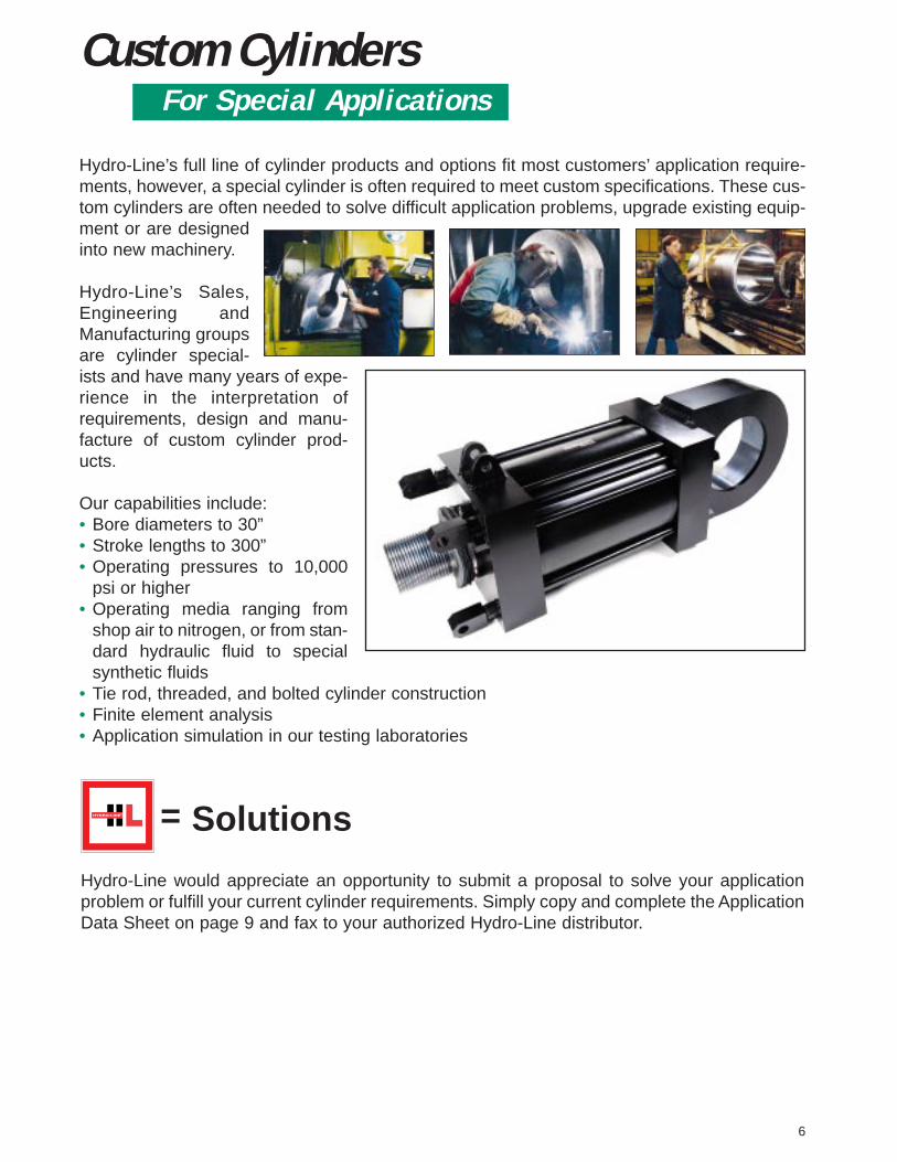
Hydro-Line’s full line of cylinder products and options fit most customers’ application require-ments, however, a special cylinder is often required to meet custom specifications. These cus-tom cylinders are often needed to solve difficult application problems, upgrade existing equip-ment or are designedinto new machinery.
Hydro-Line’s Sales,Engineering andManufacturing groupsare cylinder special-ists and have many years of expe-rience in the interpretation ofrequirements, design and manu-facture of custom cylinder prod-ucts.
Our capabilities include:• Bore diameters to 30”• Stroke lengths to 300”• Operating pressures to 10,000
psi or higher• Operating media ranging from
shop air to nitrogen, or from stan-dard hydraulic fluid to specialsynthetic fluids
• Tie rod, threaded, and bolted cylinder construction • Finite element analysis• Application simulation in our testing laboratories
6
Custom CylindersFor Special Applications
Hydro-Line would appreciate an opportunity to submit a proposal to solve your applicationproblem or fulfill your current cylinder requirements. Simply copy and complete the ApplicationData Sheet on page 9 and fax to your authorized Hydro-Line distributor.
= Solutions

DescriptionSpecify in inches (2 position decimal)NoncushionedCushioned both endsCushioned head endCushioned cap endSpecify in inches (2 position decimal)Specify in inches (2 position decimal)Include ONLY for double-rod cylinderSide lugs, MS2Side tapped, MS4Cap fixed clevis, MP1Cap detachable clevis, MP2Side end lugs, MS7Head rectangular flange, MF1Head square flange, MF5No mountAll tie rods extended, MX1Head end tie rods extended, MX3Cap end tie rods extended, MX2Cap rectangular flange, MF2Cap square flange, MF6Intermediate fixed trunnion, MT4Head trunnion, MT1Cap trunnion, MT2Air 250 psiAir prelubricated 250 psiHydraulic 400 psiMale, largeMale, large, extendedMale, small (standard)Male, small, extended◆ Male modifiedFemale◆ Female modifiedPlain endMale, full rod diameterMale, for rod end coupling◆ ModifiedNPTFSAEManifoldFlangeBSP/G◆ SpecialUrethane Ultra-SealNitrile lip typeNitrile ELF rounded lip typePolyPakViton PolyPakViton lip typeUltra-Seal with scraperNitrile lip type with scraperViton PolyPak with scraperViton lip type with scraper◆ SpecialNitrile lip typeNitrile ELF rounded lip typeLow friction PolyPakPolyPak* Viton Lip TypeLow breakaway Teflon radial seal with
wearbandMagnetic piston (2 switches) Hall EffectMagnetic piston (1 switch) Hall EffectMagnetic piston (no switches) Hall EffectMagnetic piston (2 switches) ReedMagnetic piston (1 switch) ReedMagnetic piston (no switches) Reed◆ SpecialHead End◆ SpecialCap End◆ Special◆ Include ONLY if special modifications arerequired.Air bleedersDrainbacksSpecial sealsNonstd. mountOversize portsBronze bushingsKey PlateStainless steel rod
Symbol–NBHC––DABC
DCEFJKLMNRSTTUWA5LA5HA5
11X2
2X2M4
4M56
10MNSMFGXHNLPFVJSGUXNLDPVB
FGHMOSX
1 thru 4X
1 thru 5X
X
FeatureRod Diameter
Cushions
StrokeBore
Double RodMounting
Style
Model Series
Rod End Style
Ports
Rod Seals
Piston Seals
PortLocations
SpecialModifications
How to Order an A5 CylinderHydro-Line standard cylinders can be completely and accurately identified with a model number that encodesconstruction specifications. To develop the model number for ordering a cylinder, see the following example:
HOW TO ORDER1. Quantity2. Model number3. Special modifications if
required4. Completed Application
Data Sheet(s) (page 9) ifrequired.
5. Required ship date
Customer Number (ifdesired)Hydro-Line Serial Number
HYDRO-LINE, INC.ROCKFORD, IL
AAAA5555KKKKDDDD----3333 .... 22225555XXXX8888 .... 00000000----NNNN----1111----2222----NNNN----NNNN----NNNN----1111----1111----XXXX111199994444000011111111222233334444----1111AAAA 11111111555577779999----333377775555
◆ Include drawing or description* If selected for high temperature, it should be specified
to pin the piston to the rod.
• Urethane Ultra -Seal is standard on HA5 hydraulic
24
3
1
Port LocationsPort location 5 is on thecenter of the back face ofthe end cap.
7
Rod bootsFour rod end flatsPort or cushion
modificationsDouble-end rod with
different rod endsSpecial paint/platingStop tube
A5KD - 3.25 X 8.00 - N - 1- 2 - N - N - N - 1 - 1 - X

DescriptionSpecify in inches (2 position decimal)NoncushionedCushioned both endsCushioned head endCushioned cap endSpecify in inches (2 position decimal)Specify in inches (2 position decimal)Include ONLY for double-rod cylinderSide lugs, MS2Side tapped, MS4Cap fixed clevis, MP1Cap detachable clevis, MP2Side end lugs, MS7Head rectangular flange, MF1Head rectangular, ME5Centerline lugs, MS3Head square flange, MF5No mountAll tie rods extended, MX1Head end tie rods extended, MX3Cap end tie rods extended, MX2Cap rectangular, ME6Cap rectangular flange, MF2Cap square flange, MF6Intermediate fixed trunnion, MT4Head trunnion, MT1Cap trunnion, MT2Air 250 psiAir prelubricated 250 psiHydraulic medium pressureMale, largeMale, large, extendedMale, small (standard)Male, small, extended◆ Male modifiedFemale◆ Female modifiedPlain endMale, full rod diameterMale, for rod end coupling◆ ModifiedNPTFSAEManifoldFlangeBSP/G◆ SpecialUrethane Ultra-SealNitrile lip typeNitrile ELF rounded lip typePolyPakViton PolyPakViton lip typeUltra-Seal with scraperNitrile lip type with scraperViton PolyPak with scraperViton lip type with scraper◆ SpecialNitrile lip typeNitrile ELF rounded lip typeLow friction PolyPakPolyPakCast iron rings* Viton Lip TypeLow breakaway Teflon radial seal with
wearband◆ SpecialHead End◆ SpecialCap End◆ Special◆ Include ONLY if special modifications arerequired.Air bleedersDrainbacksSpecial sealsNonstd. mountOversize portsBronze bushingsKey PlateStainless steel rodStop Tube
Symbol–NBHC––DABC
DCEFGHJKLMNPRSTTUWR5
LR5HR5
11X2
2X2M4
4M56
10MNSMFGXHNLPFVJSGUXNLDPRVB
X1 thru 4
X1 thru 5
X
X
FeatureRod Diameter
Cushions
StrokeBore
Double RodMounting
Style
Model Series
Rod End Style
Ports
Rod Seals
Piston Seals
PortLocations
SpecialModifications
How to Order an R5 CylinderHydro-Line standard cylinders can be completely and accurately identified with a model number that encodes constructionspecifications. To develop the model number for ordering a cylinder, see the following example:
HOW TO ORDER1. Quantity2. Model number3. Special modifications if
required4. Completed Application
Data Sheet(s) (page 9) ifrequired.
5. Required ship date
Customer Number (if desired)Hydro-Line Serial Number
HYDRO-LINE, INC.ROCKFORD, IL
RRRR5555KKKKDDDD----3333 .... 22225555XXXX8888 .... 00000000----NNNN----1111----2222----NNNN----NNNN----NNNN----1111----1111----XXXX
111199994444000011111111222233334444----1111AAAA 11111111555577779999----333377775555
◆ Include drawing or description* If selected for high temperature, it should be specified
to pin the piston to the rod.
• Urethane Ultra -Seal is standard on HA5 hydraulic
24
3
1
8
Rod bootsIndicator switchesFour rod end flatsPort or cushionmodifications
Double-end rod withdifferent rod ends
Special paint/plating
Port LocationsPort location 5 is on thecenter of the back face of the end cap.
R5KD - 3.25 X 8.00 - N - 1- 2 - N - N - N - 1 - 1 - X

9
Hydro-Line Application Data Sheet
FRM-24-005
PREPARED BY: DATE: REVIEWED BY: DATE:
CUSTOMER DRAWING NUMBER: REVISION DATES: HYDRO-LINE QUOTE NUMBER:
APPLICATION SKETCH: DESCRIPTION OF APPLICATIONOR SPECIAL REQUIREMENT:
WHAT INDUSTRY IS THE CYLINDER WHAT TYPE OF MACHINE IS THE WHAT IS THE CYLINDER NAMEUSED IN? CYLINDER USED ON? THE APPLICATION?
WHAT IS THE PRESENT PROBLEM?
WHAT IS THE PRESENT CYLINDER TYPE AND MODEL NUMBER?
WHAT ENVIRONMENTAL CONDITIONS IS THE CYLINDER SUBJECTED TO?
Standard Factory Corrosive Washdown Chemical? Outdoors Other
WHAT IS MOUNTING?Attitude Rod End Connection Kno wn Side LoadVertical Angle Horizontal Firmly Guided
Degrees From Vertical Supported lbs.Rod Up Rod Up Unsupported Rod Down Rod Down
WHAT IS THE OPERATING ENVIRONMENT?Fluid Media Operating Pressure Temperature at CylinderAir Minimum psi Minimum °FOil Typical psi Typical °FOther Maximum psi Maximum °FFluid Type
WHAT IS THE WORK BEING PERFORMED?Load Rod Speed Cycles per Min utePush lbs. Extend in./sec.Pull lbs. Retract in./sec. (in and out)
Company Name:
Contact:
Phone Number: Fax Number:
Distributor Name:
Contact:
Phone Number: Fax Number: ______________
Model Numbering System
Stop Tube Length Trunnion XI Dimension Stainless Steel Rod TypeHEAD CAP HEAD CAP HEAD CAP
Double End Needle Bronze Drain- Ind. ModelRod Style Additional Rod Length Location Keyplate 4-Flat Bleeders Bushing back Switch Prefix
Model/Series Mount Bore Stroke Cushion Rod Diameter Rod End Style Ports Rod Piston Head Cap Model
• • •
QUANTITY
C C
Please fill in all available information above. Refer to the Hydro-Line Model Numbering System on Pages 2.
Seals Port Location

10
R5 and A5 Series Cylinder Types
Back-to-Back CylindersBack-to-back cylinders are two single rod cylinders mountedtogether at the caps. Combinations of positions are possiblethrough various combinations of piston actuation. Consult Hydro-Line for maximum operating pressure.
Spring Return/Extend CylindersSpring return/extend cylinders provide thrust in one direction only(can be either direction). One port is used for pressure to actagainst the load while the inactive port is vented. An internal springis used to return the cylinder to its normal position.
Pumping UnitsPumping units consist of a standard hydraulic cylinder coupledwith a volume displacing lance cylinder via tie-bars. Special sealsand lance surface treatments are available to provide compatibili-ty with resins and chemicals used in the pumping process. Singleand double ended designs are available.
Systems CylindersSystems cylinders integrate position sensing and control valvesto produce a complete servoactuator package. Hydro-Line’sunique HLT In-Cylinder magnetostrictive feedback sensor providesa compact, robust package. External magnetostrictive (with protec-tive covers) or internally mounted linear potentiometer transduc-ers provide additional options. Valve, manifold blocks and a vari-ety of servocontrol valves may be added to yield a complete con-trol solution. (See Hydro-Line’s Systems Catalog for more informa-tion.)
Multiple Position CylindersMultiple position cylinders are similar to tandem cylinders (exceptthat the piston and rod assemblies are not connected) in that theoutput force is increased. Additionally, they may act as a precisionmultiple positioning device by actuating each cylinder successivelyor independently. Consult Hydro-Line for maximum operating pressure.
Single/Double Acting CylindersStandard R5 & A5 Series cylinders are double acting, with fluidpower driving the piston in both directions. Single acting cylin-ders have fluid power driving the piston in one direction, relyingon either the load or an external force to return the piston afterthe pressure is released.
Double End Cylinders Back-to-BackDouble end cylinders mounted back-to-back have common pistonrod and tie rods and the same stroke length. Consult Hydro-Linefor maximum operating pressure.
Tandem CylindersTandem cylinders consist of two cylinders interconnected (pistonand rod assemblies are connected). Pressure can act on twoeffective piston areas allowing the cylinder to be used as a forcemultiplier. This type of cylinder can also be used in air/oil systemsto provide smooth, metered flow because of equal volumes inone chamber of both cylinders. Consult Hydro-Line for maximumoperating pressure. NOTE: Front cylinder stroke is 1/8" longer atfront cylinder when strokes are the same.
Adjustable Stroke CylindersAdjustable stroke cylinders are furnished with a stroke adjustingscrew in the cap end of the cylinder. Adjusting this screw in or outlimits the retract stroke to the precise length desired.
Non-Rotating CylindersNon-rotating cylinders are furnished with internal guide rodswhich prevent piston rod rotation throughout the stroke.Rotational torque and stroke length determine the amount anddiameter of the guide rods.

DESCRIPTION HYDRO-LINE NFPA R5 BORES A5 BORESMOUNT DESIGNATION AVAILABLE AVAILABLE
Head RectangularFlange F MF1 1”-6” 11/2”-6”Cap Rectangular Flange R MF2 1”-6” 11/2”-6”Head Square Flange J MF5 1”-6” 11/2”-6”Cap Square Flange S MF6 1”-6” 11/2”-6”Integral Square Head G ** 8”-20” N/AIntegral Square Cap P ** 8”-20” N/ATie Rods Extended L, N, M MX1, MX2, 1”-20” 11/2”-6”
MX3Head Rectangular G ME5** 11/2”-6” N/ACap Rectangular P ME6** 11/2”-6” N/ANo Mount K N/A 1”-20” 11/2”-6”
DESCRIPTION HYDRO-LINE NFPA R5 BORES A5 BORESMOUNT DESIGNATION AVAILABLE AVAILABLE
Cap Fixed Clevis C MP1** 1”-20” 11/2”-6”Detachable Clevis DC MP2 11/2”-6” 11/2”-6”Head Trunnion U MT1** 1”-20” 11/2”-6”Cap Trunnion W MT2** 1”-20” 11/2”-6”IntermediateFixed Trunnion TT MT4** 11/2”-14” 11/2”-6”
DESCRIPTION HYDRO-LINE NFPA R5 BORES A5 BORESMOUNT DESIGNATION AVAILABLE AVAILABLE
Side Lugs A MS2 1-20” 11/2”-6”
Side Tapped B MS4 11/2”-20” 11/2”-6”
Center-Line Lugs H MS3** 11/2”-20” N/A
Side End Lugs E MS7 11/2”-14” 11/2”-6”
End MountingsThe head and cap rectangular mounts Gand P should be used for hydraulic appli-cations to avoid excessive deflection whichoccurs on the F and R mountings.
The G, P, J and B mounts are useable inboth push and pull at full rated hydraulicpressures as shown on page 23.
On the following bore and rod combinations:1” bore with 1/2” and 5/8” rod, 11/2” bore with1” rod, 2” bore with 13/8” rod and 21/2” borewith 13/4” rod, the G mounting is not available.Use Head Rectangular Flange mounting Fon pull applications and Cap RectangularFlange mounting R on push applicationsfor these sizes or mountings J and S.
R5 and A5 Series Mounting Application Data
Side and Center-Line MountingsThese mounts should be keyed or pinnedto prevent shifting during operation. Keysor pins must be strong enough to resist thefull thrust of the cylinder. The lugs on A andH mounts are large enough to accommodatedowel pins. Extended key plates for stockand custom cylinder models are availablewhen specified. Pin or key the head wheneverpossible. Do not pin or key both ends.Cylinders become longer when pressure isapplied and tube will tend to buckle.
The alignment and center-line height onthe E mount are maintained by accuratelymachined surfaces on the head and capwhich are held against the mounting surfaceby the end lugs.
End and Intermediate PivotMountingsTrunnion and pivot pins are designed tocarry shear loads only. Trunnion and pivotbearings must fit closely for the entirelength of the pin. Hold the trunnion bearingsrigidly and in accurate alignment.
** NFPA mounting dimensions are available on all cylinders 1 1/2”-6” bore. For larger cylinders, seepages 18-21 for mounting dimensions.
Double Rod CylindersDouble rod cylinders are available in all mountings except C, DC, E, N, P, R, S (with 2:1 rods, 11/2” through 21/2” bore) andW. Use the basic dimensional information on page 17 combined with dimensions in the drawings on pages 12-15.
Mounting AccessoriesSee pages 26-29 for mounting accessories.
11

1” - 6” bore cylinders
LB★
ZF ★
P ★
G J FH
YRODDIA.MMKK
AC
VF
K EE(2)
R
ESQ
TFUF
2 4
3
1
B
RM
FB‡ DFLATS
R
LB★
ZB★
P ★
ESQ
TFUF
G J K
Y
24
3
1 RODDIA.MMKK
AVB
FHW
BFLATSD
FB
EE(2)RM
C
R
LB★
ZJ ★
P ★
ESQ
TFUF
G J
YK
2 4
3
1RODDIA.MMKK
A CV
F B
RM
FB‡
St’d cushion adj. locationcap rectangular end
DFLATS
EE(2)
R
LB★
ZB★
P ★
ESQ
TFUF
G J K
Y
24
3
1 RODDIA.MMKK
AC
VF
WFSt’d cushionadj. locationhead rectangular end.
BD
RM
FBFLATS
EE(2)
‡
EE(2)
ESQRB
D
AA
24
3
1
RM
FLATS
LB★
ZT★
P ★
G J
Y
RODDIA.MMKK
A
C VBFH
W
DD
BBBB
K
R5F & A5F – Head Rectangular Flange Mount (NFPA Style MF1) R5R & A5R – Cap Rectangular Flange Mount (NFPA Style MF2)
R5P – Cap Rectangular Mount (NFPA Style ME6)
Not available on A5 Series
Not available on A5 Series
R5G – Head Rectangular Mount (NFPA Style ME5)Not available on following sizes:1” bore, 1/2” & 5/8” rod diameter11/2” bore, 1” rod diameter2” bore, 13/8” rod diameter21/2” bore, 13/4” rod diameter
RA2
1
3
4
CRMDIA. Ref. V
F
12
R5 and A5 SeriesMounting Dimensions
*Mounting styles L and M use filler plate at the head endwhen cylinder has circular retainer.
R5L & M & A5L & M – Tie Rods Extended Mounts (NFPA Style MX1, MX3)
(MX1) L – Both tie rods extended (MX3) M – Head end tie rods extended
RodBore Dia. F RA RM V11/2
5/811/32 1.94 23/8
9/32
2 1 1/2 2.44 25/83/8
21/2 13/819/32 2.94 31/4
13/32
31/413/4
19/32 3.44 37/817/32
2 19/32 3.69 4 17/32
4 21/219/32 – 47/16
21/32
53 23/32 – 51/4
17/32
31/223/32 5.25 55/8
17/32
G-Mounting Retainer DimensionsNOTE: Use the below chart for the cartridge retainer plate dimensions for
the bore and rod combinations listed.

BORE 1* 11/2 2 21/2 31/4 4 5 6
A 5/8 3/4 3/4 3/4 11/8 11/8 11/8 15/8
AA 1.53 2.02 2.6 3.1 3.9 4.7 5.8 6.9
AC N/A 11/8 11/8 11/8 11/2 11/2 11/2 13/4
AD N/A 5/8 5/8 5/8 15/16 15/16 15/16 11/16
AE N/A 1/4 1/4 1/4 3/8 3/8 3/8 3/8
AF N/A 3/8 3/8 3/8 11/16 11/16 11/16 7/8
B-.001
-.003BB 3/4 1 11/8 11/8 13/8 13/8 113/16 113/16
C 3/8 3/8 3/8 3/8 1/2 1/2 1/2 5/8
CC 7/16-20 1/2-20 1/2-20 1/2-20 7/8-14 7/8-14 7/8-14 11/4-12
D 3/8 17/32 17/32 17/32 7/8 7/8 7/8 11/8
DD 10-32 1/4-28 5/16-24 5/16-24 3/8-24 3/8-24 1/2-20 1/2-20
E 11/2 2 21/2 3 33/4 41/2 51/2 61/2
EE NPTF 1/4 3/8 3/8 3/8 1/2 1/2 1/2 3/4
EE SAE #6 #6◆ #6 #6 #10 #10 #10 #12
F ▲ ▲ ▲ 11/32 1/2 1/2 1/2 19/32
FB‡ 1/4 5/16 3/8 3/8 7/16 7/16 9/16 9/16
FH 3/8 3/8 3/8 3/8 5/8 5/8 5/8 3/4
FT 1/2-20 5/8-18 5/8-18 5/8-18 1-14 1-14 1-14 13/8-12
G 11/2 11/2 11/2 11/2 13/4 13/4 13/4 2
J 1 1 1 1 11/4 11/4 11/4 11/2
K 3/16 1/4 5/16 5/16 3/8 3/8 7/16 7/16
KK 5/16-24 7/16-20 7/16-20 7/16-20 3/4-16 3/4-16 3/4-16 1-14
LB★ 31/2 35/8 35/8 33/4 41/4 41/4 41/2 5
MM 1/2 5/8 5/8 5/8 1 1 1 13/8
P NPTF★ 21/8 23/16 23/16 25/16 25/8 25/8 27/8 31/8
P SAE★ 21/16 21/4 21/4 23/8 29/16 29/16 213/16 31/16
R 1.08 1.43 1.84 2.19 2.76 3.32 4.10 4.88
RM § § § 23/8 25/8 25/8 25/8 31/4
TF 2 23/4 33/8 37/8 411/16 57/16 65/8 75/8
UF 21/2 33/8 41/8 45/8 51/2 61/4 75/8 85/8
V ▲ ▲ ▲ 9/32 3/8 3/8 3/8 13/32
VB 1/4 1/4 1/4 1/4 1/4 1/4 1/4 1/4
W 5/8 5/8 5/8 5/8 3/4 3/4 3/4 7/8
WF N/A 1 1 1 13/8 13/8 13/8 15/8
Y NPTF 115/16 131/32 131/32 131/32 27/16 27/16 27/16 213/16
Y SAE 131/32 131/32 131/32 131/32 27/16 27/16 27/16 213/16
ZB★ 411/16 47/8 415/16 51/16 6 6 65/16 71/16
ZF★ 47/8 5 5 51/8 61/4 61/4 61/2 73/8
ZJ★ N/A 45/8 45/8 43/4 55/8 55/8 57/8 65/8
ZT★ 51/4 55/8 53/4 57/8 7 7 711/16 87/16
LB★
ZF
P ★
G J
Y
FH
RODDIA.MMKK
A
C VF
K
★
EE(2)
R
ER SQ
TF
TF
UFSQ
2 4
3
1
B
RM
DFLATS
FB‡
EE(2)
R
LB★
ZB★
P ★
E
R SQ
TF
TF
UFSQ
G JK
Y
24
3
1 RODDIA.MMKK
A
C VBFH
WB
FLATSD
RM
FB‡
LB★
★ZT
P ★
G J K
YRODDIA.MMKK
DD
AV
FW
KBB
E SQRB
D
AA
24
3
1
FLATS
EE(2)RM
C
R5S & A5S – Cap Square Flange Mount (NFPA Style MF6)
R5J & A5J – Head Square Flange Mount (NFPA Style MF5)
R5N & A5N – Cap End Tie Rods Extended Mounts (NFPA Style MX2)
End Mountings
1 11/8 11/8 11/8 11/2 11/2 11/2 2
Cylinder Dimensions
Dimensions shown in green are mounting dimensions.NOTE: To determine piston thickness, subtract G and J dimensions from
LB dimension.NOTE: Additional port information on page 24.
Oversize rods affect dimensions in gray-shaded areas. See pages 32-33 for these dimensions.
★ Add stroke to all starred dimensions.§ Refer to Figure 5-1 on page 5.NOTE: Overall length dimensions that require addition of stroke may vary
from dimensions shown, due to manufacturing tolerances.▲ Use FH dimension in place of F dimension and VB dimension in place
of V dimension.‡ Use screws 1/16” smaller than mounting holes.◆ NOTE: On cushioned rod end 11/2” bore cylinders with one inch rod, a
welded boss is required on rod end cap.* A5 Series cylinders not available in 1” bore.
13

1” – 6” bore cylinders
EE(2)
ST
SS★
ZB★
P ★
ETSUS
SB‡
G J
Y
K
XS
24
1
3
BD
FLATS
SQ
RM
SW
LB★
SU SU
RODDIA.MMKK
A CVF
SW
ST
SS★
ZB★
P ★
ESQ
TSUS
SB‡ G J
Y
K
XS
24
1
3
BD
FLATS
RM
-.005-.010
SW
LB★
SU SU
RODDIA.MMKK
AC
VF
SW
E2
EE (2)
LB ★★
ZE
SE
★
★
P
EL
EO
RODDIA.MMKK
A
WG
K
CVB
FH
Y
★XE
J
2
E
BD
BL
FLATS
SQ
4
EE(2)1
3ET
EB‡
-.005-.010
E2
EG
DIA. COUNTERBORE(2) HOLES HEAD END ONLYEF
1/64 APPROX.
RMEE(2)
SN★
ZB★
P★
E
TK
G J
Y
K
XT
24
1
3
TN NT TAP
DFLATS
SQ
LB★
RODDIA.MMKK
AC V
F
B
RM
-.005-.010
E2
R5A & A5A – Side Lugs Mount (NFPA Style MS2) R5H – Center-Line Lugs Mount (NFPA Style MS3)(Not available in 1” bore)
Not available on A5 Series
R5 and A5 SeriesMounting Dimensions
R5B & A5B – Side Tapped Mount (NFPA Style MS4)(not available in 1” bore)
R5E & A5E – Side End Lugs (NFPA Style MS7)(not available in 1” bore single rod or double rod and 11/2”through 2/2” bore double rod cylinders with 2:1 rod diameters.)
NOTE: Bottoms of heads and caps are mounting surfaces.Lugs hold cylinder against mounting surface.
NOTE: To determine piston thickness, subtract G and J dimensions fromLB dimension.
14
NOTE: Order Series R5 for air service; LR5 for pre-lubricated air service;HR5 for medium pressure hydraulic service by adding the desiredseries to the mounting style number. (Example: R5A or LR5A orHR5A.)

BORE 1* 11/2 2 21/2 31/4 4 5 6A 5/8 3/4 3/4 3/4 11/8 11/8 11/8 15/8
AC N/A 11/8 11/8 11/8 11/2 11/2 11/2 13/4AD N/A 5/8 5/8 5/8 15/16 15/16 15/16 11/16
AE N/A 1/4 1/4 1/4 3/8 3/8 3/8 3/8AF N/A 3/8 3/8 3/8 11/16 11/16 11/16 7/8
B-.001-.003BL 1.08 1.43 1.84 2.19 2.76 3.32 4.10 4.88C 3/8 3/8 3/8 3/8 1/2 1/2 1/2 5/8
CC 7/16-20 1/2-20 1/2-20 1/2-20 7/8-14 7/8-14 7/8-14 11/4-12D 3/8 17/32 17/32 17/32 7/8 7/8 7/8 11/8E 11/2 2 21/2 3 33/4 41/2 51/2 61/2
EB‡ N/A 5/16 3/8 3/8 7/16 7/16 9/16 9/16
EE NPTF 1/4 3/8 3/8 3/8 1/2 1/2 1/2 3/4EE SAE #6 #6◆ #6 #6 #10 #10 #10 #12
EF N/A 1/2 1/2 1/2 N/A N/A 7/8 7/8EG N/A 7/16 15/32 5/8 N/A N/A 11/4 11/4EL N/A 3/4 15/16 11/16 7/8 1 11/16 1EO N/A 1/4 5/16 5/16 3/8 3/8 1/2 1/2ET N/A 9/16 3/4 7/8 1 11/4 11/2 15/8F ▲ ▲ ▲ 11/32 1/2 1/2 1/2 19/32
FH▲ 3/8 3/8 3/8 3/8 5/8 5/8 5/8 3/4FT 1/2-20 5/8-18 5/8-18 5/8-18 1-14 1-14 1-14 13/8-12G 11/2 11/2 11/2 11/2 13/4 13/4 13/4 2J 1 1 1 1 11/4 11/4 11/4 11/2K 3/16 1/4 5/16 5/16 3/8 3/8 7/16 7/16
KK 5/16-24 7/16-20 7/16-20 7/16-20 3/4-16 3/4-16 3/4-16 1-14LB★ 31/2 35/8 35/8 33/4 41/4 41/4 41/2 5MM 1/2 5/8 5/8 5/8 1 1 1 13/8NT N/A 1/4-20 5/16-18 3/8-16 1/2-13 1/2-13 5/8-11 3/4-10
P NPTF★ 21/8 23/16 23/16 25/16 25/8 25/8 27/8 31/8P SAE★ 21/16 21/4 21/4 23/8 29/16 29/16 213/16 31/16
RM § § § 23/8 25/8 25/8 25/8 31/4SB‡ 9/32 7/16 7/16 7/16 9/16 9/16 13/16 13/16
SE★ N/A 51/2 57/8 61/4 65/8 67/8 71/4 73/4SN★ N/A 21/4 21/4 23/8 25/8 25/8 27/8 31/8SS★ 27/8 27/8 27/8 3 31/4 31/4 31/8 35/8ST 5/16 1/2 1/2 1/2 3/4 3/4 1 1SU 3/4 15/16 15/16 15/16 11/4 11/4 19/16 19/16
SW 5/16 3/8 3/8 3/8 1/2 1/2 11/16 11/16
TK N/A 3/8 1/2 5/8 3/4 3/4 1 11/8TN N/A 5/8 7/8 11/4 11/2 21/16 211/16 31/4TS 21/8 23/4 31/4 33/4 43/4 51/2 67/8 77/8UF 21/2 33/8 41/8 45/8 51/2 61/4 75/8 85/8US 23/4 31/2 4 41/2 53/4 61/2 81/4 91/4V ▲ ▲ ▲ 9/32 3/8 3/8 3/8 13/32
VB▲ 1/4 1/4 1/4 1/4 1/4 1/4 1/4 1/4W 5/8 5/8 5/8 5/8 3/4 3/4 3/4 7/8
XE★ N/A 53/8 59/16 513/16 61/2 65/8 615/16 75/8XS 15/16 13/8 13/8 13/8 17/8 17/8 21/16 25/16
XT N/A 115/16 115/16 115/16 27/16 27/16 27/16 213/16
Y NPTF 115/16 131/32 131/32 131/32 27/16 27/16 27/16 213/16
Y SAE 131/32 131/32 131/32 131/32 27/16 27/16 27/16 213/16
ZB★ 411/16 47/8 415/16 51/16 6 6 65/16 71/16
ZE★ N/A 55/8 57/8 61/8 67/8 7 71/16 81/8
★
P ★Y
ZB
★LBG K
RODDIA.MMKK
A
FHESQ
24
1
3
BD
FLATS
RM
JW
VB-.013-.015
C
EE (2)
FH 2
LB★
★ZB
P ★
G J K
YRODDIA.MMKK
AC
VF
W
KEE(2)
ESQ
B
D
24
3
1
RM
FLATS
R
R5 & A5 – Extended Key Plate – Available when specified
R5K & A5K – No Mount
Side and Center-Line Mountings
Dimensions shown in green are mounting dimensions.NOTE: To determine piston thickness, subtract G and J dimension from LB dimen-
sion.NOTE: Additional port information on page 24.
Oversize rods affect dimensions in gray-shaded areas. See pages 32-33 for these dimensions.
★ Add stroke to all starred dimensions.§ Refer to Figure 5-1 on page 5.NOTE: Overall length dimensions that require addition of stroke may vary from
dimensions shown, due to manufacturing tolerances.▲ Use FH dimension in place of F dimension and VB dimension in place of V
dimension.‡ Use screws 1/16” smaller than mounting holes.◆ NOTE: On cushioned rod end 11/2” bore cylinders with one inch rod, a welded
boss is required on rod end cap.* A5 Series Cylinders not available in 1” bore.
Cylinder Dimensions
15
1 11/8 11/8 11/8 11/2 11/2 11/2 2

1” – 6” bore cylinders
TD24
EE (2)
EUT
TL
1
3
BD
FLATS
SQ
RM
TL
±.001
J K
ZB★
G
PY ★
RODDIA.MMKK
AC
VF
LB★XG
TD
J K
ZB★
24
G
EE(2)
EUT
TL
1
3
BD
FLATS
SQ
RM
TL
PY ★
RODDIA.MM
KK
AC
VF
LB★
★XJ
±.001
TD
J K
ZB★
24
G
EE NPT(2)
EUM
TL
1
3
BD
FLATS
SQ
RM
TMTL
PY★
RODDIA.MMKK
AC
XI
VF
LB★
BD
Customer to Specify
UV ±.001
25˚*
EE(2)
MR
LRCD
M
K
LB★
P ★
ESQ
G J
Y
L M
XC★
2 4
CW CW
RODDIA.MM
A
KK
C VF
1
3
FLATSD
RM
CB†
B
EE(2)
MR
LRCD
M
K
LB★
P ★
E
CBSQ
G J FH
Y
L M
XD ★
2 4 B
CW CW
RODDIA.MM
A
KK
C VF
1
3
FLATSD
25˚*
RM
†
R5W & A5W – Cap Trunnion Mount (NFPA Style MT2) R5U & A5U – Head Trunnion Mount (NFPA Style MT1)
R5 and A5 SeriesMounting Dimensions
R5C & A5C – Cap Fixed Clevis Mount (NFPA Style MP1) R5TT & A5TT – Intermediate Fixed Trunnion Mount (NFPA Style MT4)(not available in 1” bore)
R5DC & A5DC – Cap Detachable Clevis Mount (NFPA Style MP2)
16
† Maximum width of mating part.R5 1” bore has single eye, CB wide
* 28° on 1” bore only.
11/2” through 6” bores only. † Maximum width of mating part.

BORE *1 11/2 2 21/2 31/4 4 5 6A 5/8 3/4 3/4 3/4 11/8 11/8 11/8 15/8
AC N/A 11/8 11/8 11/8 11/2 11/2 11/2 13/4AD N/A 5/8 5/8 5/8 15/16 15/16 15/16 11/16
AE N/A 1/4 1/4 1/4 3/8 3/8 3/8 3/8AF N/A 3/8 3/8 3/8 11/16 11/16 11/16 7/8
B-.001-.003BD N/A 11/4 11/2 11/2 2 2 2 2C 3/8 3/8 3/8 3/8 1/2 1/2 1/2 5/8
CB† 7/16 3/4 3/4 3/4 11/4 11/4 11/4 11/2CC 7/16-20 1/2-20 1/2-20 1/2-20 7/8-14 7/8-14 7/8-14 11/4-12CD 7/16 1/2 1/2 1/2 3/4 3/4 3/4 1CW N/A 1/2 1/2 1/2 5/8 5/8 5/8 3/4D 3/8 17/32 17/32 17/32 7/8 7/8 7/8 11/8E 11/2 2 21/2 3 33/4 41/2 51/2 61/2
EE NPTF 1/4 3/8 3/8 3/8 1/2 1/2 1/2 3/4EE SAE #6 ◆#6 #6 #6 #10 #10 #10 #12
EL N/A 3/4 15/16 11/16 7/8 1 11/16 1EO N/A 1/4 5/16 5/16 3/8 3/8 1/2 1/2F ▲ ▲ ▲ ▲ 11/32 1/2 1/2 1/2 19/32
FH▲ 3/8 3/8 3/8 3/8 5/8 5/8 5/8 3/4FT 1/2-20 5/8-18 5/8-18 5/8-18 1-14 1-14 1-14 13/8-12G 11/2 11/2 11/2 11/2 13/4 13/4 13/4 2J 1 1 1 1 11/4 11/4 11/4 11/2K 3/16 1/4 5/16 5/16 3/8 3/8 7/16 7/16
KK 5/16-24 7/16-20 7/16-20 7/16-20 3/4-16 3/4-16 3/4-16 1-14L 1/2 3/4 3/4 3/4 11/4 11/4 11/4 11/2
LB★ 31/2 35/8 35/8 33/4 41/4 41/4 41/2 5LD★ 4 41/8 41/8 41/4 43/4 43/4 5 51/2LR 15/32 9/16 9/16 9/16 11/16 11/16 11/16 15/16
M 7/16 1/2 1/2 1/2 3/4 3/4 3/4 1MM 1/2 5/8 5/8 5/8 1 1 1 13/8MR 17/32 9/16 9/16 9/16 11/16 11/16 11/16 11/8
P NPTF★ 21/8 23/16 23/16 25/16 25/8 25/8 27/8 31/8P SAE★ 21/16 21/4 21/4 23/8 29/16 29/16 213/16 31/16
SP★ N/A 63/8 63/4 71/8 73/4 8 83/8 9SU 3/4 15/16 15/16 15/16 11/4 11/4 19/16 19/16
SV★ 33/8 33/8 33/8 31/2 33/4 33/4 35/8 41/8SX★ N/A 21/4 21/4 23/8 25/8 25/8 27/8 31/8RM N/A § § 23/8 25/8 25/8 25/8 31/4TD 3/4 1 1 1 1 1 1 13/8TL 3/4 1 1 1 1 1 1 13/8TM N/A 21/2 3 31/2 41/2 51/4 61/4 75/8UM N/A 41/2 5 51/2 61/2 71/4 81/4 103/8UT 3 4 41/2 5 53/4 61/2 71/2 91/4UV N/A 21/2 3 31/2 41/4 5 6 7V ▲ ▲ ▲ 9/32 3/8 3/8 3/8 13/32
VB▲ 1/4 1/4 1/4 1/4 1/4 1/4 1/4 1/4W 5/8 5/8 5/8 5/8 3/4 3/4 3/4 7/8
XC★ 5 53/8 53/8 51/2 67/8 67/8 71/8 81/8XD★ N/A 53/4 53/4 57/8 71/2 71/2 73/4 87/8XG 13/4 13/4 13/4 13/4 21/4 21/4 21/4 25/8
XJ★ 4 41/8 41/8 41/4 5 5 51/4 57/8XS 15/16 13/8 13/8 13/8 17/8 17/8 21/16 25/16
XT N/A 115/16 115/16 115/16 27/16 27/16 27/16 213/16
XX N/A 61/4 67/16 611/16 75/8 73/4 81/16 87/8Y NPTF 115/16 131/32 131/32 131/32 27/16 27/16 27/16 213/16
Y SAE 131/32 131/32 131/32 131/32 27/16 27/16 27/16 213/16
ZB★ 411/16 47/8 415/16 51/16 6 6 65/16 71/16
ZL★ 53/8 51/2 51/2 519/32 65/8 65/8 67/8 723/32
ZM★★ 6 61/8 61/8 61/4 71/2 71/2 73/4 83/4
SV★
★
ZM + 2X STROKE
P ★Y
ZL
XS
LD★
SU SU SWSW
E - .0052 - .010
17
R5AD & A5AD – Side Lugs Mount – Double Rod
SX★
ZM + 2X STROKE
ZL
XT
E - .0052 - .010
(4X)NT TAPTK DEEP
LD★
★
R5BD & A5BD – Side Tapped Mount – Double Rod
LD★
★
ZM + 2X STROKE
SP
★XX
EL ELEOEO
R5ED & A5ED – Side End Lugs Mount – Double Rod
NOTE: R5HD has mounting dimensions identical to R5AD.NOTE: Add D for double end after the R5 series and mounting
style. (Example: R5AD)NOTE: Dimensions not shown are same as single rod cylinders.NOTE: Double rod cylinders available in all mounts except C,
DC, E (with 2:1 rods, 11/2” – 21/2” bore) and W.NOTE: Order Series R5 or A5 for air service; LR5 or LA5 for
prelubricated air service; HR5 or HA5 for medium pressurehydraulic service by adding the desired series to themounting style number. (Example: R5Aor LR5Aor HR5A.)
NOTE: To determine piston thickness, subtract G and Gdimensions from LD dimension.
Pivot Mountings and DoubleRod Cylinders
§
1 11/8 11/8 11/8 11/2 11/2 11/2 2
Cylinder Dimensions
Dimensions shown in green are mounting dimensions.NOTE: To determine piston thickness, subtract G
and J dimensions from LB dimension.NOTE: Additional port information on page 24.
Oversize rods affect dimensions in gray-shaded areas. See pages 32-33 for these dimensions
★ Add stroke to all starred dimensions.★★ Plug 2x Stroke† Maximum width of mating part.§ Refer to Figure 5-1 on page 5.
NOTE: Overall length dimensions that requireaddition of stroke may vary from dimensionsshown, due to manufacturing tolerances.
▲ Use FH dimension in place of F dimension andVB dimension in place of V dimension.
‡ Use screws 1/16” smaller than mounting holes.◆ NOTE: On cushioned rod end 11/2” bore cylin-
ders with one inch rod, a welded boss isrequired on rod end cap.
* A5 Series cylinders not available in 1” bore.

BORE 16" 18" 20"RA 7.475 8.396 9.266RB 5.234 5.879 6.488
TIE RODTHREAD
TD
J K
ZB★
24
G
EE (2)
ESQ
UT
TL
1
3
BD
FLATS
RM
TL
PY ★
RODDIA.MMKK
AC V
F
LB★
★XJ
±.001
8” – 20” bore cylinders
ZJ ★
P ★
GJ
Y
LB
RODDIA.MMKK
A
C VF
EE(2)
TE
ESQ
2 4
3
1
BD
RM
EBFLATS
TE
K
ZJ ★
P ★
GJ
YRODDIA.MMKK
A
C VF
K
EE(2)
TE
ESQ
2244
3
1
BD
RM
EB‡FLATS
TE
TD24
EE (2)
EUT
TL
1
3
BD
FLATS
SQ
RM
TL
±.001
J K
ZB★
G
PY ★
RODDIA.MMKK
AC
VF
LB★XG
R5G – Head Square Mount (NFPA Style ME3) R5P – Cap Square Mount (NFPA Style ME4)
R5 SeriesMounting Dimensions
R5U – Head Trunnion Mount (NFPA Style MT1) R5W – Cap Trunnion Mount (NFPA Style MT2)
Tie Rod Information
To make torquing easier, and to permit use of standard sizetools on large-bore cylinders, two tie rods are used at eachcorner of the 16, 18 and 20-inch bore sizes. This alsoreduces flexure of head and cap under pressure.
8, 10, 12, 14 bore tie rod configuration
Dimensions shown in green are mounting dimensions.
NOTE: Order Series R5 for air service; LR5 for prelubricat-ed air service; HR5 for medium pressure hydraulicservice by adding the desired series to the mount-ing style number. (Example: R5A or LR5A orHR5A.)
18
RB
R
RB
RA
RA
1-14 11/8-12 11/4-12

BORE 8 10 12 14 16 18 20A 15/8 2 21/4 3 31/2 4 4
AA 9.1 11.2 13.3 15.4 18.25 20.50 22.62AC 13/4 2 25/8 31/4 43/8 41/2 41/2AD 11/16 15/16 111/16 115/16 211/16 211/16 211/16
AE 3/8 1/2 5/8 3/4 1 1 1AF 7/8 11/8 13/8 13/4 21/2 3 3
B-.001-.003BB 25/16 211/16 211/16 33/16 35/8 41/8 41/2BD 21/2 3 3 31/2 N/A N/A N/AC 5/8 3/4 7/8 1 1 1 1
CB† 11/2 2 21/2 21/2 31/2 4 4CC 11/4-12 11/2-12 13/4-12 21/4-12 31/4-12 33/4-12 33/4-12CD 1 13/8 13/4 2 2 21/2 21/2CW 3/4 1 11/4 11/4 13/4 2 2D 11/8 11/2 13/4 21/8 3 ▼ ▼
DD 5/8-18 3/4-16 3/4-16 7/8-14 1-14 11/8-12 11/4-12E 81/2 105/8 123/4 143/4 171/2 191/2 213/4
EB‡ 11/16 13/16 13/16 15/16 15/16 19/16 113/16
EE NPTF 3/4 1 1 11/4 11/2 11/2 2EE SAE #12 #16 #16 #20 #20 #24 #32
F 19/32 19/32 19/32 19/32 23/32 7/8 7/8FB 11/16 13/16 13/16 15/16 15/16 19/16 113/16
FT 13/8-12 13/4-12 2-12 21/2-12 31/2-12 4-12 4-12G 2 21/4 21/4 23/4 27/8 33/8 37/8J 11/2 2 2 21/4 27/8 33/8 37/8K 9/16 11/16 11/16 13/16 15/16 1 11/8
KK 1-14 11/4-12 11/2-12 17/8-12 21/2-12 3-12 3-12L 11/2 21/8 21/4 21/2 31/2 41/4 43/4
LB★ 51/8 63/8 67/8 81/8 91/4 101/4 113/4LR 13/16 113/16 115/16 23/16 3 33/4 41/4M 1 13/8 13/4 2 23/4 31/4 33/4
MM 13/8 13/4 2 21/2 31/2 4 4MR 11/8 13/4 17/8 21/8 23/4 31/4 33/4
P NPTF★ 31/4 41/8 45/8 51/2 61/2 61/2 73/8P SAE★ 31/4 315/16 47/16 51/4 57/8 61/4 71/4
R 6.44 7.92 9.40 10.90 § § §
RM 31/4 37/8 4 47/16 55/8 67/16 67/16
TD 13/8 13/4 13/4 2 N/A N/A N/ATE 7.57 9.40 11.10 12.87 14.75 16.50 18.25TL 13/8 13/4 13/4 2 23/4 3 31/2TM 93/4 12 14 161/4 N/A N/A N/AUM 121/2 151/2 171/2 201/4 N/A N/A N/AUT 111/4 141/8 161/4 183/4 23 251/2 283/4UV 91/2 113/4 133/4 16 N/A N/A N/AV 13/32 17/32 17/32 21/32 17/32 3/8 3/8
WF 15/8 17/8 2 21/4 21/4 21/4 21/4XC★ 81/4 103/8 111/8 127/8 15 163/4 183/4XG 25/8 3 31/8 35/8 311/16 315/16 43/16
XIXJ★ 6 71/4 77/8 91/4 101/16 1013/16 121/16
Y NPTF 213/16 31/8 31/4 313/16 35/8 41/8 47/16
Y SAE 213/16 37/32 311/32 315/16 315/16 41/4 41/2ZB★ 75/16 815/16 99/16 113/16 127/16 131/2 151/8ZJ★ 63/4 81/4 87/8 103/8 111/2 121/2 14ZT★ 91/16 1015/16 119/16 139/16 151/8 165/8 181/2
2 23/8 25/8 31/8 41/4 43/4 43/4
TD
J K
ZB★
24
G
EE NPT(2)
EUM
TL
1
3
BD
FLATS
SQ
RM
TMTL
PY★
RODDIA.MMKK
AC
XI
VF
LB★
BD
Customer to Specify
UV ±.001
R5TT – Intermediate Fixed Trunnion Mount (NFPA Style MT4)
R5C – Cap Fixed Clevis Mount (NFPA Style MP1)
25˚*
EE(2)
MR
LRCD
M
K
LB★
P ★
ESQ
G J
Y
L M
XC★
2 4
CW CW
RODDIA.MM
A
KK
C VF
1
3
FLATSD
RM
CB†
B
R5L, M, N – Tie Rods Extended Mounts (NFPA Style MX1, MX2, MX3)
LB★
ZT
P ★
G J K
YRODDIA.MMKK
DD
AC
VF
BBEE (2)
E SQRB
D
AA
24
3
1
RM
FLATS
★
Cylinder DimensionsEnd and Pivot Mountings
Dimensions shown in green are mounting dimensions.NOTE: To determine piston thickness, subtract G and J dimensions from
LB dimension.Oversize rods affect dimensions in gray-shaded areas. See pages 32-33 for these dimensions.
★ Add stroke to all starred dimensions.‡ Use screws 1/16” smaller than mounting holes.▼ (4) spanner holes used instead of flats on 4” diameter and larger. § See tie rod information on page 18.NOTE: Overall length dimensions that require addition of stroke may vary
from dimensions shown, due to manufacturing tolerances.
19
† Maximum width of mating part.
NOTE: For trunnion dimensions on 16", 18" and 20" bores, consult factory.
(MX1) L – Both tie rods extended(MX2) N – Cap end tie rods extended(MX3) M – Head end tie rods extended
CUSTOMER TO SPECIFY

8” – 20” bore cylinders
EE(2)
ST
SS★
ZB★
P ★
ETSUS
SB‡
G J
Y
K
XS
24
1
3
BD
FLATS
SQ
RM
SW
LB★
SU SU
RODDIA.MMKK
A CVF
SW
ST
SS★
ZB★
P ★
ETSUS
SB G J
Y
K
XS
24
1
3
BD
FLATS
SQ
RM
-.005-.010
SW
LB★
SU SU
RODDIA.MMKK
A
C VF
SW
E2
EE(2)
‡
LB ★★
ZE
SE
★
★
P
EL
EO
RODDIA.MMKK
A
WFG
K
C VF
Y
★XE
J
2
ESQ
BD
BL
FLATS
4
EE (2)1
3ET
EB‡
-.005-.010
E2
1/64 APPROX.
RM
R5A – Side Lugs Mount (NFPA Style MS2) R5H – Center-Line Lugs Mount (NFPA Style MS3)
R5 SeriesMounting Dimensions
R5E – Side End Lugs Mount (NFPA Style MS7)(not available in 16”- 20” bores)
R5B – Side Tapped Mount (NFPA Style MS4)
EE(2)
SN★
ZB★
P★
E
TK
G J
Y
K
XT
24
1
3
TN NT TAP
DFLATS
SQ
LB★
RODDIA.MMKK
AC V
F
B
RM
-.005-.010
E2
NOTE: Bottoms of heads and caps are mounting surfaces. Lugs hold cylinders against mounting surface.
20

BORE 8 10 12 14 16• 18• 20•A 15/8 2 21/4 3 31/2 4 4
AC 13/4 2 25/8 31/4 43/8 41/2 41/2AD 11/16 15/16 111/16 115/16 211/16 211/16 211/16
AE 3/8 1/2 5/8 3/4 1 1 1AF 7/8 11/8 13/8 13/4 21/2 3 3
B-.001-.003BL 6.44 7.92 9.40 10.90 N/A N/A N/AC 5/8 3/4 7/8 1 1 1 1
CC 11/4-12 11/2-12 13/4-12 21/4-12 31/4-12 33/4-12 33/4-12D 11/8 11/2 13/4 21/8 3 ▼ ▼
E 81/2 105/8 123/4 143/4 171/2 191/2 213/4EB‡ 11/16 13/16 13/16 15/16 N/A N/A N/A
EE NPTF 3/4 1 1 11/4 11/2 11/2 2EE SAE #12 #16 #16 #20 #20 #24 #32
EL 11/8 15/16 15/16 11/2 N/A N/A N/AEO 5/8 5/8 5/8 3/4 N/A N/A N/AET 2 23/4 37/16 37/8 N/A N/A N/AF 19/32 19/32 19/32 19/32 23/32 7/8 7/8
FT 13/8-12 13/4-12 2-12 21/2-12 31/2-12 4-12 4-12G 2 21/4 21/4 23/4 27/8 33/8 37/8J 11/2 2 2 21/4 27/8 33/8 37/8K 9/16 11/16 11/16 13/16 15/16 1 11/8
KK 1-14 11/4-12 11/2-12 17/8-12 21/2-12 3-12 3-12LB★ 51/8 63/8 67/8 81/8 91/4 101/4 113/4LD★ 55/8 65/8 71/8 85/8 91/4 101/4 113/4MM 13/8 13/4 2 21/2 31/2 4 4NT 3/4-10 1-8 1-8 11/4-7 13/4-12 2-12 21/4-12
P NPTF★ 31/4 41/8 45/8 51/2 61/2 61/2 73/8P SAE★ 33/16 315/16 47/16 51/4 57/8 61/4 71/4
RM 31/4 37/8 4 47/16 55/8 67/16 67/16
SB‡ 13/16 11/16 11/16 15/16 113/16 21/16 25/16
SE★ 73/8 9 91/2 111/8 N/A N/A N/ASN★ 31/4 41/8 45/8 51/2 61/2 7 73/4SP★ 77/8 91/4 93/4 115/8 N/A N/A N/ASS★ 33/4 45/8 51/8 57/8 53/4 61/4 7ST 1 11/4 11/4 11/2 2 21/2 3SU 19/16 2 2 21/2 31/2 31/2 35/8
SV★ 41/4 47/8 53/8 63/8 53/4 61/4 7SX★ 31/4 41/8 45/8 51/2 61/2 7 73/4SW 11/16 7/8 7/8 11/8 13/4 2 23/8TK 11/8 11/2 11/2 17/8 3 31/4 33/4TN 41/2 51/2 71/4 83/8 7 8 81/2TS 97/8 123/8 141/2 17 21 231/2 261/2US 111/4 141/8 161/4 191/4 241/4 271/2 311/4V 13/32 17/32 17/32 21/32 17/32 3/8 3/8
WF 15/8 17/8 2 21/4 21/4 21/4 21/4XE★ 77/8 99/16 103/16 117/8 N/A N/A N/AXS 25/16 23/4 27/8 33/8 4 41/4 45/8XT 213/16 31/8 31/4 313/16 311/16 315/16 43/16
XX★ 83/8 913/16 107/16 123/8 N/A N/A N/AY NPTF 213/16 31/8 31/4 313/16 35/8 41/8 47/16
Y SAE 213/16 37/32 311/32 315/16 315/16 41/4 41/2ZB★ 75/16 815/16 99/16 113/16 127/16 131/2 151/8ZE★ 81/2 103/16 1013/16 125/8 N/A N/A N/AZL★ 727/32 93/32 923/32 1115/32 127/32 133/8 147/8ZM 87/8 103/8 111/8 131/8 133/4 143/4 161/4
SV★
★
ZM + 2X STROKE
P ★Y
ZL
XS
LD★
SU SU SWSW
E - .0052 - .010
R5AD – Side Lugs Mount – Double Rod
SX★
ZM + 2X STROKE
ZL
XT
E - .0052 - .010
(4X)NT TAPTK DEEP
LD★
★
R5BD – Side Tapped Mount – Double Rod
LD★
★
ZM + 2X STROKE
SP
★XX
EL ELEOEO
R5ED – Side End Lugs Mount – Double Rod
NOTE: R5HD has mounting dimensions identical to R5AD.NOTE: Add D for double end after the R5 series and mounting
style.(Example: R5AD)
NOTE: Dimensions not shown are same as single rod cylinders.NOTE: Double rod cylinders available in all mounts except C,
DC and W.NOTE: Order Series R5 for air service; LR5 for prelubricated
air service; HR5 for medium pressure hydraulic serviceby adding the desired series to the mounting style number.(Example: R5A or LR5A or HR5A.)
NOTE: To determine piston thickness, subtract G and Gdimensions from LD dimension.
Side, Center-Line Mountings and Double Rod Cylinders
2 23/8 25/8 31/8 41/4 43/4 43/4
Cylinder Dimensions
Dimensions shown in green are mounting dimensions.NOTE: To determine piston thickness, subtract G and J dimensions from LB dimension.NOTE: Additional port information on page 24.
Oversize rods affect dimensions in gray-shaded areas. See pages 32-33 for these dimensions.
★ Add stroke to all starred dimensions.• Mounting E not available in these sizes.NOTE: Overall length dimensions that require addition of stroke may vary from dimensions
shown, due to manufacturing tolerances.§ See tie rod information on page 18‡ Use screws 1/16” smaller than mounting holes.▼ (4) Spanner holes used instead of flats on 4” diameter and larger.NOTE: The interchangeability of the 16”, 18” and 20” bores with other brands has not been
established by the NFPAThe above dimensions are Hydro-Line standards.
21

SS
TT
DD
SS
TT
DD
SS
TT
DD
SS
TT
SS
TT
SS
TT
D = 4SUNSUPPORTED ROD END
D = SSUPPORTED ROD END
D = 1/2 SFIRMLY GUIDED ROD END
D = 4SUNSUPPORTED ROD END
D = SSUPPORTED ROD END
Hydro-Line Technical DataRod Size And Stop Tube Selection
Rod Size Selection:Standard rod sizes are normally suitable for all applications except forlong stroke or high thrust applications. Proper selection of minimum rodsize may be determined by the following steps:1. With knowledge of bore size and operating pressure, thrust may be
determined. Refer to the graph in the next column.2. Select from illustrations above the type of mounting to be used and
determine the length of D with the piston rod in the fully extended position.3. Find the value of D at the bottom of the graph and follow its line vertically
until it intercepts the horizontal line representing the maximum pushthrust that will be applied to your cylinder. The intersection of these twolines will fall within a stripe representing the minimum recommendedpiston rod diameter for your application.
Stop tubes are located between the piston and the rod shoulder on thehead end of the cylinder. Bearing loading is reduced by separating thepiston and the rod bushing. Bearing wear and tendency to buckle isreduced.
To determine if a stop tube is required and the length of stop tube needed,use the following procedure:
Determine the value of D with the piston rod in the fully extended position.If the value of D is under 40”, no stop tube is needed. If D is greaterthan 40”, one inch of stop tube is recommended for each 10” or fractionthereof beyond 40”.
Special note: When specifying stroke and stop tube lengths, pleaseinclude net working stroke plus stop tube length.
Rod Bushing
Stop TubePiston
CAP CLEVISOR TRUNNION
INTERMEDIATETRUNNION
HEADTRUNNION
D = 1/2 SFIRMLY GUIDED ROD END
22
600,000400,000300,000200,000
100,00080,00060,00040,00030,00020,000
10,0008,0006,000
2,000
4,0003,000
1,000
600800
400300
200
1008060
0 50 100 150 250 350 450 500400300200
VALUE OF "D" IN INCHES
AX
IAL
TH
RU
ST
"T
" IN
PO
UN
DS
"DIA.
85/1"
DIA.DIA.
83/1 "DIA.
43/1 "2"DIA.
DIA.2 "
3"DIA.
DIA.3 "
4"DIA.
DIA.21/4 "
5"DIA.
DIA.2
1/5 "
21/
21/
Stop Tubes:

1/2 .20 10 12 16 20 40 50 100 150 200 300 400 600 .00090 .00010 .000075/8 .31 16 19 25 31 62 78 155 233 310 465 620 930 .00138 .00018 .001161 .79 40 47 63 79 158 198 395 593 790 1,185 – – .00342 .00046 .00294
13/8 1.49 75 89 119 149 298 373 745 1,118 – – – – .00645 .00086 .0055513/4 2.41 121 145 193 241 482 603 1,205 – – – – – .01043 .00139 .008982 3.14 157 188 251 314 628 785 1,570 – – – – – .01359 .00182 .01170
21/2 4.91 246 295 393 491 982 1,228 2,455 – – – – – .02126 .00284 .018303 7.07 354 424 566 707 1,414 1,768 3,535 – – – – – .03061 .00409 .02635
31/2 9.62 481 577 770 962 1,924 2,405 4,810 – – – – – .04165 .00557 .035854 12.57 629 754 1,006 1,257 2,514 3,143 6,285 – – – – – .05442 .00727 .04685
41/2 15.90 795 954 1,272 1,590 3,180 3,975 7,950 – – – – – .06883 .00920 .059265 19.63 982 1,178 1,570 1,963 3,926 4,908 9,815 – – – – – .08498 .01136 .07316
51/2 23.76 1,188 1,426 1,901 2,376 4,752 5,940 11,880 – – – – – .10286 .01375 .08855
1 200 3000 .79 40 47 63 79 158 198 395 593 790 1,185 1,580 2,356 .00340 .00050 .0032011/2 200 1500 1.84 92 110 147 184 368 460 920 1,380 1,840 2,760 – – .00797 .00106 .006832 200 1500 3.24 162 194 259 324 648 810 1,620 2,430 3,240 4,860 – – .01403 .00188 .01211
21/2 200 1000 5.03 252 302 402 503 1,006 1,258 2,520 3,773 5,030 – – – .02177 .00291 .0187531/4 200 1500 8.45 423 507 676 845 1,690 2,113 4,230 6,338 8,450 12,675 – – .03658 .00489 .031494 200 1000 12.76 638 766 1,021 1,276 2,552 3,190 6,380 9,570 12,760 – – – .05524 .00738 .047555 200 750 19.87 994 1,192 1,590 1,987 3,974 4,968 9,940 14,903 – – – – .08602 .01150 .074056 200 750 28.56 1,428 1,714 2,285 2,856 5,712 7,140 14,280 21,420 – – – – .12364 .01653 .106448 200 500 50.64 2,532 3,038 4,051 5,064 10,128 12,660 25,320 – – – – – .21922 .02931 .18873
10 200 500 79.01 3,951 4,741 6,321 7,901 15,802 19,753 39,510 – – – – – .34203 .04572 .2944612 200 400 113.66 5,683 6,820 9,093 11,366 22,732 28,415 56,830* – – – – – .49203 .06578 .4235914 200 400 154.60 7,730 9,276 12,368 15,460 30,920 38,650 77,300* – – – – – .66926 .08947 .5761716 200 500 201.82 10,091 12,109 16,146 20,182 40,364 50,455 109,910 – – – – – .87368 .11679 .7521518 200 500 255.32 12,766 15,319 20,426 25,532 51,064 63,830 127,660 – – – – – 1.10528 .14775 .9515420 200 500 315.10 15,755 18,906 25,208 31,510 63,020 78,775 157,550 – – – – – 1.36407 .18235 1.17433
Cyl.Bore
inInches
LA5A5
LR5R5
HA5*HR5
PistonArea
Sq. In.50psi
60psi
80psi
100psi
200psi
250psi
500psi
750psi
1000psi
1500psi
2000psi
3000psi
OilGallons
Displaced
AirPressureCubic Ft.Displaced
Free AirCubic Ft.@ 80 psi
Displaced
Standard OperatingPressure Rating Out-Stroke Thrust In Pounds Force Consumption Per Inch
Of Stroke in One Direction
Hydro-Line Technical DataPressure-Thrust-Consumption-Flow Charts
PistonRod
Dia.inInches
PistonRodArea
Sq. In. 50psi
60psi
80psi
100psi
200psi
250psi
500psi
750psi
1000psi
1500psi
2000psi
3000psi
OilGallons
Displaced
AirPressureCubic Ft.Displaced
Free AirCubic Ft.@ 80 psi
Displaced
In-Stroke Pull In Pounds ForceDeduct The Following Force Or Consumptions Corresponding To Rod Size From Out-Stroke Thrust
Or Consumptions To Determine In-Stroke Pull Or Consumptions
Consumption Per InchOf Stroke in One Direction
R5LR5HR5
Pressures of Operating Medium–Air or Hydraulic
11, 11/2, 2 & 21/2
31/4, 4, 56, 8101214–
1618, 20
–––
1/2 .622 .304 4.7 .157 9.4 .585 14.1 1.215 18.6 2.065 23.5 3.130 28.2 4.343/4 .824 .533 8.3 .117 16.6 .370 24.9 .710 33.2 1.520 41.5 2.300 49.8 3.171 1.049 .864 13.5 .090 26.9 .323 40.4 .673 53.8 1.555 67.3 1.725 80.8 2.44
11/4 1.380 1.495 23.3 .064 46.5 .231 69.8 .488 93.0 .755 116.3 1.240 139.6 1.7411/2 1.610 2.036 31.7 .054 63.4 .181 95.1 .404 126.8 .691 158.5 1.042 190.2 1.482 2.067 3.355 52.3 .047 104.5 .169 156.8 .360 209.0 .609 261.3 .927 313.6 1.11
Pipe Size
Standard Weight PipeVel. = 5 Ft. Per Sec. Vel. = 10 Ft. Per Sec. Vel. = 15 Ft. Per Sec. Vel. = 20 Ft. Per Sec. Vel. = 25 Ft. Per Sec. Vel. = 30 Ft. Per Sec.
Oil Flow Gallons Per Minute And Friction Pressure Drop Pounds Per Square Inch Per Foot Length Of Pipe
1/2 .622 .304 1.5 3.3 .35 17 6 to 30 12 to 603/4 .824 .533 2.2 4.5 .47 22 10 to 50 20 to 1001 1.049 .864 2.7 5.8 .60 28 13 to 65 25 to 125
11/4 1.380 1.495 3.7 7.7 .81 37 15 to 75 30 to 15011/2 1.610 2.036 4.4 9.2 .92 44 20 to 100 40 to 2002 2.067 3.355 5.5 12.0 1.20 57 25 to 125 50 to 250
Standard Weight Pipe
23
* 400 psi maximum operating pressure for HA5Below are cylinder sizes for which therod diameters in the column to the leftare standard. Consult bulletins for rodslarger than standard.
Thrusts for pressures not shown intable, add the thrust for two or moreoperating pressures which combinedequal the desired pressure.
1 Gallon = 231 Cubic InchesOil consumption gal. per min = Gal. per in. times in. per min. piston speedAir consumption cubic ft. per min = Cu. ft. per in. times in. per min. piston speedFree air consumption per in. of stroke = Cu. ft. displaced x (press. + 14.7) ÷ 14.7
NOTE: Bore Dimensions Are 0.030” Larger Than NOMINAL except for 1” bore.
Pipe Size Chart for Hydraulic Cylinders and Systems
The pressure drop shown in the above table is for ordinary wrought iron pipe.For smooth, new wrought iron pipes, multiply the values shown by .7; for verysmooth, straight tubing, multiply the values shown by .54. Pressure drop is thesame regardless of operating pressure. Avoid large pressure drops in lowpressure systems. Note that oil flows through large pipes at high velocity (upto 30 ft. per sec.) with small pressure loss. The pressure drop shown is forhydraulic oil with approximately 225 SSU at 100°F under average operatingconditions. The values also apply to water. In order to accommodate largepump volumes without severe pressure drops, all Hydro-Line hydraulic cylindersare available with oversize ports with welded half pipe couplings or flange fitting.
* Inside diameter and areas shown are standard pipe. For tubing or extraheavy and double extra heavy pipe, use I.D. in table closest to your pipe ortubing I.D.
Pressures of Operating Medium – Air or Hydraulic
InsideDiameter*
AreaSq. In.
Gallons per
Minute
PressureDropin psi
Gallons per
Minute
PressureDropin psi
Gallons per
Minute
PressureDropin psi
Gallons per
Minute
PressureDropin psi
Gallons per
Minute
PressureDropin psi
Gallons per
Minute
PressureDropin psi
Equivalent Length of Straight Pipein Feet for Various Fitting
PipeSize
InsideDiameter*
AreaSq. In.
Std.Elbow
Std.Tee
GateValve
GlobeValve
Cylinders& 2-3 Way
Valves
4-Way Valves

1 1/2 5/8 3000 1800
11/25/8 1 1500 1600
2 5/8 1 13/8 1500 1500
21/25/8 1, 13/8 13/4 1000 1000
31/4 1 13/8, 13/4 2 1500 900
4 1 13/8, 13/4, 2 21/2 1000 650
5 1 13/8, 13/4, 2, 21/2, 3 31/2 750* 650
6 13/8 13/4, 2, 21/2, 3, 31/2 4 750 500
8 13/8 13/4, 2, 21/2, 3, 31/2, 4, 41/2, 5 51/2 500 600
10 13/4 2, 21/2, 3, 31/2, 4, 41/2, 5, 51/2 500 550
12 2 21/2, 3, 31/2, 4, 41/2, 5, 51/2 400 400
14 21/2 3, 31/2, 4, 41/2, 5, 51/2 400 400
16 31/2 4, 41/2, 5, 51/2 500 750
18 4 41/2, 5, 51/2 500 720
20 4 41/2, 5, 51/2 500 650
Manifold
“A’’Mount
“B’’Mount
NPT
OversizeStd.
CylinderBore
(inches) Standard Oversize
Piston Rod Diameters (inches)
2:1Heavy-Duty
Service
4:1 DesignFactory(Yield)†
Pressure Ratings (psi)
* Use 13/8” diameter rod or larger in 5-inch bore pull applications withover 700 psi heavy-duty or 1110 psi nonshock operating pressure.
† Based on minimum yield point of weakest component and standardrod size.
NOTE: R5 and LR5 Series for air service only. Pressures up to 200 psi air.NOTE: Maximum operating pressure 400 psi for A5.
★ Consult factory.★★ Port adapter 1” in diameter and 3/4” high furnished on head end only
on 11/2” bore cylinders with 1” diameter rod.
R5 and A5 Cylinder PortSize Data and Port,Cushion Adjustment andBall Check LocationInformation
Hydraulic Pressure Ratings (R5 Only)
24
PortsStandard ports for HR5, HA5 and WBR5 are SAE straightthread. R5, LR5, A5 and LA5 standard ports are NPT.
Optional and Oversize PortsThe chart at right lists port sizes. Larger welded half-pipecoupling ports are available in some sizes, please contactHydro-Line. For oversize ports where short restrictions indash pot areas cannot be allowed, specify “full flow porting.”
Head HeadCap Cap
CylinderBore Dia.(inches)
CylinderRod Dia.(inches) Std.
SAE
Oversize
1”
11/2”★★
2”
21/2”
31/4”
4”
5”
6”
8”
10”
12”
14”
16”
18”
20”
1/2”5/8”5/8”1”
5/8”1”
13/8”5/8”1”
13/8”13/4”1”
13/8”13/4”2”1”
13/8”13/4”2”
21/2”1”
13/8”13/4”2”
21/2”3”
31/2”13/8”13/4”2”
21/2”3”
31/2”4”
13/8”13/4”2”
21/2”3”
31/2”4”
41/2”5”
51/2”13/4”2”
21/2”3”
31/2”4”
41/2”5”
51/2”2”
21/2”3”
31/2”4”
41/2”5”
51/2”21/2”
3”31/2”
4”41/2”
5”51/2”31/2”
4”41/2”
5”51/2”
4”41/2”
5”51/2”
4”41/2”
5”51/2”
#6 N/A N/A 1/4” 3/8” 3/8” 1/4” N/A#6 N/A N/A 1/4” 3/8” 3/8” 1/4” N/A#6 N/A N/A 3/8” N/A N/A 1/2” 3/16”#6 N/A N/A 3/8” N/A N/A 1/2” 3/16”#6 #8 N/A 3/8” 1/2” N/A 1/2” 1/4”#6 N/A N/A 3/8” N/A N/A 1/2” 1/4”#6 N/A N/A 3/8” N/A N/A 1/2” 1/4”#6 #8 N/A 3/8” N/A N/A 1/2” 1/2”#6 #8 N/A 3/8” N/A N/A 1/2” 1/2”#6 N/A N/A 3/8” N/A N/A 1/2” 1/2”#6 N/A N/A 3/8” N/A N/A 1/2” 1/2”
#10 #12 N/A 1/2” 3/4” N/A 5/8” 5/8”#10 #12 N/A 1/2” 3/4” N/A 5/8” 5/8”#10 N/A N/A 1/2” 3/4” N/A 5/8” 5/8”#10 N/A N/A 1/2” N/A N/A 5/8” 5/8”#10 #12 N/A 1/2” N/A N/A 5/8” 5/8”#10 #12 N/A 1/2” N/A N/A 5/8” 5/8”#10 #12 N/A 1/2” N/A N/A 5/8” 5/8”#10 #12 N/A 1/2” N/A N/A 5/8” 5/8”#10 N/A N/A 1/2” N/A N/A 5/8” 5/8”#10 #12 N/A 1/2” N/A N/A 5/8” 5/8”#10 #12 N/A 1/2” N/A N/A 5/8” 5/8”#10 #12 N/A 1/2” N/A N/A 5/8” 5/8”#10 #12 N/A 1/2” N/A N/A 5/8” 5/8”#10 #12 N/A 1/2” N/A N/A 5/8” 5/8”#10 N/A N/A 1/2” N/A N/A 5/8” 5/8”#10 N/A N/A 1/2” N/A N/A 5/8” 5/8”#12 #14 N/A 3/4” N/A N/A 13/16” 13/16”#12 #14 N/A 3/4” N/A N/A 13/16” 13/16”#12 #14 N/A 3/4” N/A N/A 13/16” 13/16”#12 #14 N/A 3/4” N/A N/A 13/16” 13/16”#12 #14 N/A 3/4” N/A N/A 13/16” 13/16”#12 #14 N/A 3/4” N/A N/A 13/16” 13/16”#12 N/A N/A 3/4” N/A N/A 13/16” 13/16”#12 #14 N/A 3/4” 1” N/A 13/16” 13/16”#12 #14 N/A 3/4” 1” N/A 13/16” 13/16”#12 #14 N/A 3/4” 1” N/A 13/16” 13/16”#12 #14 N/A 3/4” 1” N/A 13/16” 13/16”#12 #14 N/A 3/4” 1” N/A 13/16” 13/16”#12 #14 N/A 3/4” 1” N/A 13/16” 13/16”#12 #14 N/A 3/4” 1” N/A 13/16” 13/16”#12 #14 N/A 3/4” 1” N/A 13/16” 13/16”#12 #14 N/A 3/4” 1” N/A 13/16” 13/16”#12 #14 N/A 3/4” 1” N/A 13/16” 13/16”#16 #20 N/A 1” N/A N/A 11/16” 11/16”#16 #20 N/A 1” N/A N/A 11/16” 11/16”#16 #20 N/A 1” N/A N/A 11/16” 11/16”#16 #20 N/A 1” N/A N/A 11/16” 11/16”#16 #20 N/A 1” N/A N/A 11/16” 11/16”#16 #20 N/A 1” N/A N/A 11/16” 11/16”#16 #20 N/A 1” N/A N/A 11/16” 11/16”#16 #20 N/A 1” N/A N/A 11/16” 11/16”#16 #20 N/A 1” N/A N/A 11/16” 11/16”#16 #20 N/A 1” N/A N/A 11/16” 11/16”#16 #20 N/A 1” N/A N/A 11/16” 11/16”#16 #20 N/A 1” N/A N/A 11/16” 11/16”#16 #20 N/A 1” N/A N/A 11/16” 11/16”#16 #20 N/A 1” N/A N/A 11/16” 11/16”#16 #20 N/A 1” N/A N/A 11/16” 11/16”#16 #20 N/A 1” N/A N/A 11/16” 11/16”#16 #20 N/A 1” N/A N/A 11/16” 11/16”#20 #24 N/A 11/4” 11/2” N/A 13/8” 13/8”#20 #24 N/A 11/4” 11/2” N/A 13/8” 13/8”#20 #24 N/A 11/4” 11/2” N/A 13/8” 13/8”#20 #24 N/A 11/4” 11/2” N/A 13/8” 13/8”#20 #24 N/A 11/4” 11/2” N/A 13/8” 13/8”#20 #24 N/A 11/4” 11/2” N/A 13/8” 13/8”#20 #24 N/A 11/4” 11/2” N/A 13/8” 13/8”#20 #24 #24 11/2” N/A N/A ★ ★
#20 #24 #24 11/2” N/A N/A ★ ★
#20 #24 #24 11/2” N/A N/A ★ ★
#20 #24 #24 11/2” N/A N/A ★ ★
#20 #24 #24 11/2” N/A N/A ★ ★
#24 #32 #32 11/2” 2” 2” ★ ★
#24 #32 #32 11/2” 2” 2” ★ ★
#24 #32 #32 11/2” 2” 2” ★ ★
#24 #32 #32 11/2” 2” 2” ★ ★
#32 N/A N/A 2” 21/2” 21/2” ★ ★
#32 N/A N/A 2” 21/2” 21/2” ★ ★
#32 N/A N/A 2” 21/2” 21/2” ★ ★
#32 N/A N/A 2” 21/2” 21/2” ★ ★
1
11/2
2
21/2
31/4
4 & 5
6
8
10
12
14
1/2
5/8
5/8
5/8
1
13/8
13/8
13/4
2
21/2
.64
.87
.87
.87
1.12
1.37
1.37
1.37
1.37
1.37
.81
.81
.81
.81
1.0
1.25
1.25
1.75
1.75
2
.291
.602
.602
.602
1.108
2.076
2.076
3.144
4.433
6.496
.074
.138
.138
.138
.331
.601
.601
.601
1.226
2.40
CUSHION LENGTHPLUNGER CROSS-SECTIONAL AREA
Standard Cushion Information
* In checking oversized rod cylinders, use the same dimensions as forstandard rods excepting the head end plunger cross-sectional area.For this, find the rod desired in the second column and use head endplunger cross-sectional area.
Refer to Technical Data form TD-213 to calculate your hydraulic cushionrequirements.
Because of space limitations, a fixed cushion only is available on thehead end in the 1” bore with 5/8” diameter rod, 11/2” bore with 1” diameterrod, 2” bore with 13/8” diameter rod, and 21/2” bore with a 13/4” diameterrod.
25
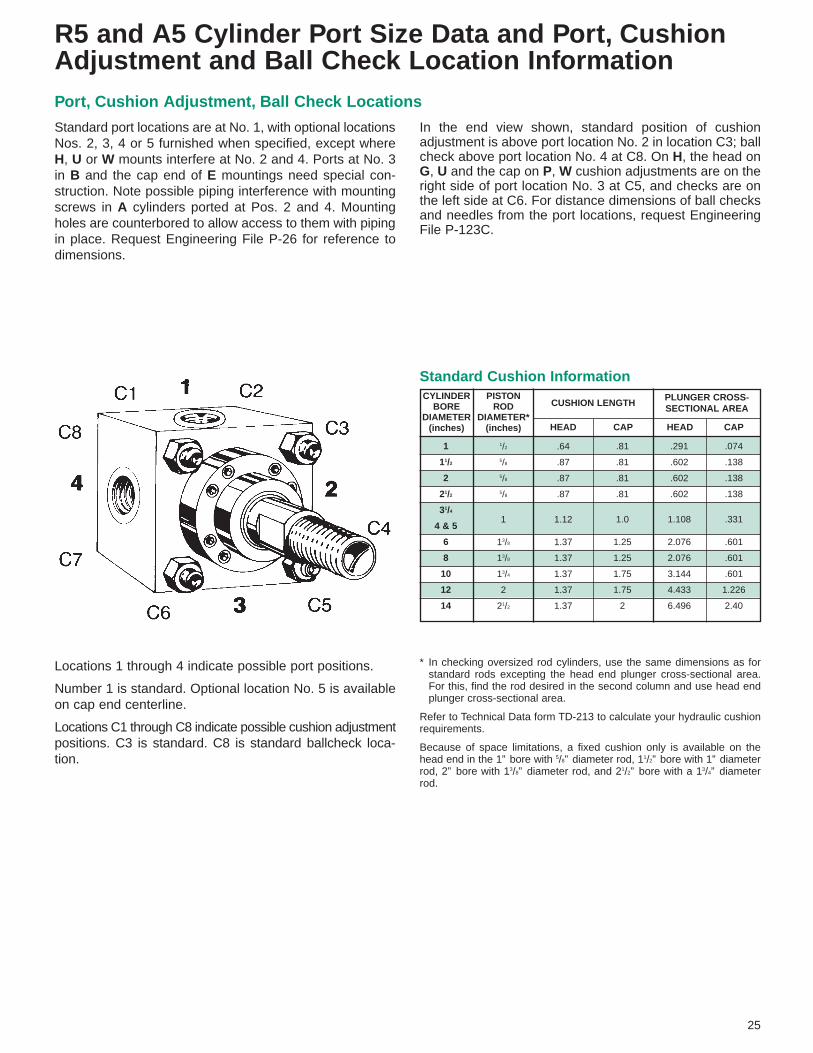
Standard port locations are at No. 1, with optional locationsNos. 2, 3, 4 or 5 furnished when specified, except whereH, U or W mounts interfere at No. 2 and 4. Ports at No. 3in B and the cap end of E mountings need special con-struction. Note possible piping interference with mountingscrews in A cylinders ported at Pos. 2 and 4. Mountingholes are counterbored to allow access to them with pipingin place. Request Engineering File P-26 for reference todimensions.
Locations 1 through 4 indicate possible port positions.
Number 1 is standard. Optional location No. 5 is availableon cap end centerline.
Locations C1 through C8 indicate possible cushion adjustmentpositions. C3 is standard. C8 is standard ballcheck loca-tion.
R5 and A5 Cylinder Port Size Data and Port, CushionAdjustment and Ball Check Location Information
In the end view shown, standard position of cushionadjustment is above port location No. 2 in location C3; ballcheck above port location No. 4 at C8. On H, the head onG, U and the cap on P, W cushion adjustments are on theright side of port location No. 3 at C5, and checks are onthe left side at C6. For distance dimensions of ball checksand needles from the port locations, request EngineeringFile P-123C.
Port, Cushion Adjustment, Ball Check Locations
CYLINDERBORE
DIAMETER(inches)
PISTONROD
DIAMETER*(inches) HEAD CAP HEAD CAP

Part No. A CA CB CD ER KK
C-9302 3/4 11/27/16
7/1619/32
5/16-24
C-9303 3/4 11/23/4
1/25/8
7/16-20
C-9304 11/8 21/16 11/43/4
7/83/4-16
C-93065 15/8 213/16 11/2 1 13/16 1-14
C-9308 2 37/16 2 13/8 19/16 11/4-12
C-9310 21/4 4 21/2 13/4 2 11/2-12
C-9312 3 5 21/2 2 21/4 17/8-12
C-9314 31/2 513/16 3 21/2 213/16 21/412
C-9316 31/2 61/8 3 3 31/4 21/2-12
C-9320 41/2 75/8 4 31/2 37/8 31/4-12
C-9324 51/2 91/8 41/2 4 47/16 4-12
Part No. AA BA CB CD CW DD E FH FJ LR M MR
CN-133-03 2.3 15/8 25/32 1/2 1/2 3/8-24 21/2 3/8 11/8 1/2 1/2 9/16
CN-133-04 2.9 21/16 19/32 3/4 5/8 1/2-20 3 5/8 17/8 1 3/4 11/16
CN-133-05 3.6 29/16 19/32 3/4 5/8 1/2-20 31/2 5/8 17/8 11/16 3/4 11/16
CN-133-065 4.6 31/4 117/32 1 3/4 5/8-18 41/2 3/4 21/4 11/4 1 11/8
CN-133-08 5.4 313/16 21/32 13/8 1 5/8-18 5 7/8 3 17/8 13/8 13/4
CN-133-10 7.0 415/16 217/32 13/4 11/4 7/8-14 61/2 7/8 31/8 2 13/4 17/8
CN-133-12 8.1 53/4 217/32 2 11/4 1-14 71/2 1 31/2 21/8 2 21/8
CN-133-14 9.3 619/32 31/32 21/2 11/2 11/8-12 81/2 1 4 25/8 21/2 21/2
CN-133-16 10.6 71/2 31/32 3 11/2 11/4-12 91/2 1 41/4 27/8 23/4 23/4
CN-133-20 13.6 95/8 41/16 31/2 2 13/4-12 125/8 111/16 511/16 35/8 31/2 31/2
CN-133-24 16.2 111/2 49/16 4 21/4 2-12 147/8 115/16 67/16 4 4 4
Part No. CB CD CE CH CW ER KK L
C-134-04 11/32 5/16 21/4 N/A 7/32 5/16 5/16-24 17/16
C-134-05 3/4 1/2 11/2 7/8 1/2 1/2 7/16-20 3/4
C-134-08 11/4 3/4 23/8 13/8 5/8 3/4 3/4-16 11/4
C-134-11 11/2 1 31/8 15/8 3/4 1 1-14 11/2
C-134-14 2 13/8 41/8 2 1 13/8 11/4-12 21/8
C-134-16 21/2 13/4 41/2 23/8 11/4 13/4 11/2-12 21/4
C-134-20 21/2 2 51/2 215/16 11/4 2 17/8-12 21/2
C-134-24 3 21/2 61/2 31/2 11/2 21/2 21/4-12 3
C-134-28 3 3 63/4 37/8 11/2 23/4 21/2-12 31/4
C-134-36 4 31/2 81/2 5 2 31/2 31/4-12 4
C-134-44 41/2 4 10 61/8 21/4 4 4-12 41/2
Part No. CD CL CP
C-9001-3 5/16 13/16 1
C-9002-3 7/16 15/16 13/4
C-9003-3 1/2 13/4 23/8
C-9004-3 3/4 21/2 31/8
C-90065-3 1 3 33/4
C-9008-3 13/8 4 43/4
C-9010-3 13/4 5 61/32
C-9012-3 2 5 61/32
C-9014-3 21/2 6 71/32
C-9016-3 3 6 71/8
C-9020-3 31/2 8 95/8
C-9024-3 4 9 105/8
1. Pivot pins are furnished with clevis mounted cylinders.2. Pivot pins must be ordered as a separate item if to be used with female eye,
female clevis, standard eye bracket and clevis bracket. They are included onlywith swivel eye bracket.
3. CL=2(CW) + CB
Pivot Pin Female Eye
Mounting Accessories
Clevis Bracket
CDCL
CP
CD
ER
CD CB
CD
CD
CA
KK
A
+.004+.002
CE
ER RADIUS
L
CB*
CD
CW CW
+.004+.002
KK TAP
CH HEX ACROSS FLATS
CB*
E FJ
BD DIA.(4) HOLES
MR
BA
BA2
M
SQ
AAB.C.
M
APPROX.
25°
CW CW
LR
FH
+ .004+ .002 CD
26
1.750
.875
.875
1.750
.218 TYP
#8 Drill (1990)THROUGH(4) HOLES
.692
.682 TYP
1.41
36 TYP
1.00
.441
.439
LINE REAM.031 x 45° CHAMBOTH SIDES
.241
.226.453.483 *
.692 .682
* Maximum width of mating partNOTE: CN-133 Clevis Bracket is not adaptable to the cylinder as an MP2 bracket.
* Maximum width of mating part
Female Clevis
CR-133-02 only

1 1 71/4 C-8902 N/A C-134-04 C-9002-3 90° 60°
11/2 11/8 67/8 C-8903 C-219-3-1 C-134-05 C-9003-3 90° 60°
2 11/8 67/8 C-8903 C-219-3-1 C-134-05 C-9003-3 90° 60°
21/2 11/8 7 C-8903 C-219-3-1 C-134-05 C-9003-3 90° 60°
31/4 17/8 91/4 C-8904 C-219-3-2 C-134-08 C-9004-3 90° 65°
4 17/8 91/4 C-8904 C-219-3-2 C-134-08 C-9004-3 90° 65°
5 17/8 91/2 C-8904 C-219-3-2 C-134-08 C-9004-3 90° 65°
6 23/8 111/4 C-89065X C-219-3-3X C-134-11 C-9065-3 80° 65°
8 23/8 113/8 C-89065X C-219-3-3X C-134-11 C-9065-3 80° 65°
10 3 141/2 C-8908 C-219-3-4 C-134-14 C-9008-3 90° 70°
12 33/8 155/8 C-8910X C-219-3-5X C-134-16 C-9010-3 75° 65°
14 4 183/8 C-8912X C-219-3-6X C-134-20 C-9012-3 75° 65°
Part No. Part No. AA BA BD CB CD E F** FL** LR M MR M MR
C-8903 C-219-3-1 2.3 15/8 13/32 3/4 1/2 21/2 3/8 11/8 1/2 1/2 9/16 11/16 11/16 8,100
C-8904 C-219-3-2 3.6 29/16 17/32 11/4 3/4 31/2 5/8 17/8 1 3/4 11/16 13/16 13/16 18,800
C-89065X C-219-3-3X 4.6 31/4 21/32 11/2 1 41/2 7/8 23/8 1 1 11/8 13/8 13/8 33,300
C-8908 C-219-3-4 5.4 313/16 21/32 2 13/8 5 7/8 3 11/8 13/8 13/4 2 2 59,800
C-8910X C-219-3-5X 7.0 415/16 29/32 21/2 13/4 61/2 11/8 33/8 13/4 13/4 17/8 21/8 21/8 102,000
C-8912X C-219-3-6X 8.1 53/4 11/32 21/2 2 71/2 11/2 4 2 2 21/8 23/8 23/8 132,000
C-8914X 9.3 619/32 15/32 3 21/2 81/2 13/4 43/4 21/2 21/2 21/2
C-8916X 10.6 71/2 19/32 3 3 91/2 2 51/4 23/4 23/4 23/4
C-8920 13.6 95/8 125/32 4 31/2 125/8 111/16 511/16 31/2 31/2 31/2
C-8924 16.2 111/2 21/32 41/2 4 147/8 115/16 67/16 37/8 4 4
1 1 61/2 C-8902 N/A N/A C-9002-3 C-9302 60°
11/2 11/8 67/8 C-8903 C-219-3-1 CN-133-03 C-9003-3 C-9303 60°
2 11/8 67/8 C-8903 C-219-3-1 CN-133-03 C-9003-3 C-9303 60°
21/2 11/8 7 C-8903 C-219-3-1 CN-133-03 C-9003-3 C-9303 60°
31/4 17/8 815/16 C-8904 C-219-3-2 CN-133-04 C-9004-3 C-9304 65°
4 17/8 815/16 C-8904 C-219-3-2 CN-133-04 C-9004-3 C-9304 65°
5 17/8 93/16 C-8904 C-219-3-2 CN-133-04 C-9004-3 C-9304 65°
6 23/8 1015/16 C-89065X C-219-3-3X CN-133-065 C-9065-3 C-93065 65°
8 21/4 111/16 C-89065 C-219-3-3 CN-133-065 C-9065-3 C-93065 65°
10 3 1313/16 C-8908 C-219-3-4 CN-133-08 C-9008-3 C-9308 70°
12 33/8 151/8 C-8910X C-219-3-5X CN-133-10 C-9010-3 C-9310 65°
14 4 177/8 C-8912X C-219-3-6X CN-133-12 C-9012-3 C-9312 65°
Typical Mounting AccessoriesFor Standard Rod Diameters Style #2
Part Number
27
Std. Swivel*Dimensions Standard
BracketSwivelBracket
Swivel BracketRecommended
Static LoadLimit in Pounds
Mounting Accessories
Swivel Eye Bracket * Standard Eye Bracket
R5 and A5 CylindersFor mounting dimensions over 14” bore, consult Hydro-Line.
For mounting dimensions over 14” bore, consult Hydro-Line.
R5 and A5 Cylinders
CB
E FL
BD DIA.(4) HOLES
MR
BA
BA2
FSQ
AAB.C.
M
APPROX.
25°
* NOTE: To assure precision fit-up, pivot pins machined to special tolerances are furnished with all swivel eye brackets, unless otherwise specified.
** Dimensions F and FL reflect revised NFPA standards. Part numbers with suffix letter X are affected.
(Includes spacersto allow swivelaction up to 7°and to maked i m e n s i o n sinterchangeablewith standard eyebracket.)
A B + STROKE
C-89 or C-219
A
C-89 or C-219C-134
D˚ C˚
A B + STROKE
C-89 or C-219 CN-133C-93
D˚
A
PIVOTS FULL 90˚
Bore A BEye Bracket
Standard SwivelFemaleClevis
Pivot Pin C° D°
Bore C B Eye BracketStandard Swivel
ClevisBracket Pivot Pin Female
Eye D°

WELD-PLATE
LOCATORPIN
MACHINEMEMBER
QUICKCONNECT-DISCONNECTCOUPLING
CouplingC-271-
RodDia.MM
AF B C D E F G H KWeldPlate
C-272-L N P
SOC.HD. CAP.Screws
S T U XBoltTorq.
Ft. Lb.
Rod End Coupling
28
Used with the Hydro-Line style 10Rod End, the Hydro-Line RodEnd Coupling provides for closelateral alignment between the rodend and machine member.
The two-piece steel couplingfeatures high tensile strengthsocket head cap screws(with safety factor designedto take full load), permitsquick assembly/disassemblyfor fast and easy installationand servicing.
To order C-271-__ and C-272-__ as an assembly, use part no. C-275-__
SMM
D
N
CAF
A A
B
L
MOUNT -05
SHE DIA.
F NO. BOLTS
G DIA.B.C.
U
MOUNT -08, -11
S
THE DIA.
F NO. BOLTS
G DIA B.C.
S
MOUNT -14, -20, -36
S
THE DIA.
F NO. BOLTS
G DIA.B.C.
S
S
H
G DIA.B.C.
S
G DIA. B.C.MOUNT-16, -24, -28, -32,-40, -44, -56, -72
TU T
U
E DIA.F NO.BOLTS
TU
X
STUX E DIA.F NO. BOLTS
MOUNT -64, -80
Typical section AAdepending on rod diameter
H
C-272-Weld PlateP DIA.
Locator Pin
C-271-Coupling
K
–
–
–
–
–
–
–
–
–
–
–
–
–
4.781
–
5.946
5
14
30
52
52
128
128
255
255
450
255
450
1090
1090
2180
2180
.398
.375
.500
.454
.348
.658
.518
.607
.671
1.088
.801
.890
1.132
.951
1.440
1.183
–
.750
1.000
1.097
.950
1.588
1.414
1.657
1.834
2.627
2.188
2.431
3.094
2.708
3.933
3.368
#10-24 x .881/4”-20 x 1.0
5/16”-18 x 1.253/8”-16 x 1.53/8”-16 x 2.0
1/2”-13 x 2.251/2”-13 x 2.755/8”-11 x 3.05/8”-11 x 3.03/4”-10 x 3.5
5/8”-11 x 3.753/4”-10 x 4.5
1”-8 x 5.5
1”-8 x 5.5
11/4”-7 x 6
11/4”-7 x 6.5
.25
.25
.25
.25
.38
.38
.38
.38
.38
.38
.38
.38
.50
.50
.50
.50
2.00
2.50
3.00
3.50
4.00
5.00
5.50
6.50
7.00
7.50
8.00
9.00
11.00
12.00
14.00
15.00
C-272-05C-272-08C-272-11C-272-14C-272-16C-272-20C-272-24C-272-28C-272-32C-272-36C-272-40C-272-44C-272-56C-272-64C-272-72C-272-80
.50
.50
.62
.75
.88
1.00
1.00
1.12
1.12
1.25
1.38
1.50
1.75
2.00
2.25
2.50
.44
.38
.56
.62
.75
.88
.88
1.00
1.00
1.12
1.25
1.38
1.50
1.50
2.00
2.00
45°
30°
30°
22° 30’15°
30° 30’15°
15°
15°
22° 30’15°
15°
15°
11° 15’15°
11° 15’
1.12
1.50
2.00
2.38
2.69
3.44
4.00
4.69
5.18
5.69
6.18
6.88
8.75
9.75
11.12
12.12
.44
.62
.69
.88
1.25
1.38
1.88
2.00
2.00
2.38
2.50
3.12
4.00
4.00
4.00
4.50
1.50
2.00
2.50
3.00
3.50
4.25
5.00
5.88
6.38
6.88
7.38
8.25
10.38
11.38
13.12
14.12
.218
.281
.343
.406
.406
.531
.531
.656
.656
.781
.656
.781
1.031
1.031
1.281
1.281
4
6
6
8
12
8
12
12
12
8
12
12
12
16
12
16
.41
.75
.94
1.18
1.44
1.88
2.38
2.62
3.12
3.62
4.00
4.50
5.94
6.69
7.50
8.25
.38
.69
.88
1.12
1.38
1.75
2.25
2.50
3.00
3.50
3.88
4.38
5.75
6.50
7.25
8.00
.625
1.000
1.375
1.750
2.000
2.500
3.000
3.500
4.000
4.500
5.000
5.500
7.000
8.000
9.000
10.000
C-271-05C-271-08C-271-11C-271-14C-271-16C-271-20C-271-24C-271-28C-271-32C-271-36C-271-40C-271-44C-271-56C-271-64C-271-72C-271-80
–
.650
.866
–
1.298
–
1.932
2.264
2.505
–
2.988
3.320
4.226
4.053
5.373
5.040

Rod Max. PullPart No. Dia. A B C D F G H J K KK At Yield
AC-2-05 5/83/4 11/4 2 1/2
5/81/2
13/16 1-14 5/167/16-20 8,320
AC-2-08 1 11/8 111/16 25/161/2
31/3213/16 11/8 13/8-12 1/2
3/4-16 35,000
AC-2-11 13/8 15/8 23/8 229/321/2 111/32 15/32 15/8 17/8-12 11/16 1-14 64,500
AC-2-14 13/4 2 25/8 319/323/4 123/32 17/16 2 21/4-12 27/32 11/4-12 82,550
AC-2-16 2 21/4 3 45/327/8 131/32 13/4 23/8 25/8-12 29/32 11/2-12 128,340
AC-2-20 21/2 3 33/4 57/16 1 215/32 21/8 3 31/4-12 15/16 17/8-12 231,000
AC-2-24 3 31/2 41/4 63/16 1 231/32 ▲ 33/8 33/4-12 13/16 21/4-12 289,200
AC-2-28 31/2 31/2 5 67/16 1 315/32 ▲ 4 41/2-12 11/2 21/2-12 342,400
AC-2-36 41/2 41/2 6 77/8 1 415/32 ▲ 43/4 51/4-12 15/8 31/4-12 475,500
AC-2-44 51/2 51/2 71/4 93/8 1 515/32 ▲ 53/4 61/2-12 17/8 4-12 750,010
One Year Normal UseHydro-Line Products are warranted for a period of one year fromdate of shipment from our plant to be free from defects in work-manship and material under correct use, normal operating con-ditions and proper applications. This warranty does not extendto goods damaged, or subjected to accident, abuse, or misuseafter shipment from our factory, nor to goods altered or repairedby anyone other than authorized Hydro-Line representatives.
DisclaimersThis one year limited warranty is the only warranty extended byHydro-Line in connection with any sale by Hydro-Line. THISWARRANTY IS IN LIEU OF ALL OTHER WARRANTIES,EXPRESS OR IMPLIED, INCLUDING WARRANTIES OF MER-CHANTABILITY AND FITNESS FOR A PARTICULAR PUR-POSE, notwithstanding disclosure to Hydro-Line of the prod-uct’s intended use. An affirmation of fact or promise made onbehalf of Hydro-Line shall not be deemed to create an expresswarranty that the goods shall conform to the affirmation of prom-ise; any description of the goods is for the sole purpose of iden-tifying them and shall not be deemed to create an express war-ranty that the goods shall conform to such description; any sampleor model is for illustrative purposes only and shall not bedeemed to create an express warranty that the goods shall con-form to the sample or model; and no affirmation or promise, ordescription, or sample or model, shall be deemed part of thebasis of the bargain.
Exclusive RemedyHydro-Line’s obligation upon breach of warranty shall be limitedto replacing or repairing at our option, free of charge, but notincluding installation, dismantling, reassembling or any other
charge, the particular product or part which inspection disclosesto have been defective at time of shipment. Inspection may beat the place of installation and use, or at our plant if returned tous at our expense including lowest transportation cost, isrequested. Written notice of such defect shall be given by cus-tomer to Hydro-Line within 30 days after such defect(s) appear.Written permission for any warranty claim return must be firstobtained from authorized Hydro-Line representatives. All returnsmust be accompanied with a complete written explanation ofclaimed defects and the circumstances of operational failure.Replacement of cylinders or parts thereof repaired under thiswarranty shall be warranted under the terms of this warranty forthe remainder of the term of the original warranty or for a periodof six months after such repair or replacement, whichever islonger. Upon expiration of the warranty, all of Hydro-Line’s obli-gations hereunder shall terminate.
IN NO EVENT SHALL HYDRO-LINE HAVE ANY LIABILITYFOR PAYMENT OF ANY CONSEQUENTIAL, INCIDENTAL,INDIRECT, SPECIAL OR TORT DAMAGES OF ANY KINDINCLUDING, BUT NOT LIMITED TO, ANY LOSS OF PROFITS,TO THE EXTENT EXCLUSION IS PERMITTED BY LAW.
This warranty states our entire and exclusive liability andbuyer’s exclusive remedy for any claim of damages in connectionwith the sale or furnishing of Hydro-Line’s products or parts,their design, suitability for use, installations or operation, or forany claimed defects therein. Goods not manufactured by Hydro-Line are furnished subject only to the Manufacturer’s war-ranties, if any, and without warranties, express or implied, byHydro-Line.
ONE YEAR LIMITED WARRANTY
Self-Aligning Coupler
▲ Four 1/2” diameter x 1/2” deep spanner holes instead of flats.NOTE: When ordering oversize and 2:1 rod cylinders, specify modification to
suit standard rod diameter’s coupler.
Lateral movement (on push only) and radial movementprovide precision alignment between cylinder andmachine. Couplers preset with proper clearances andcompletely lubricated at factory before shipping.
29
������������@@@@AABBBBCC������������ÀÀÀÀÁÁÂÂÂÂÃÃ������������@@@@AABBBBCC������������ÀÀÀÀÁÁÂÂÂÂÃÃ������������@@@@AABBBBCC������������ÀÀÀÀÁÁÂÂÂÂÃÃ��������������
����
��@@
AABB
CC��
����
��ÀÀ
ÁÁÂÂ
ÃÃ��
����
��@@
AABB
CC��
����
��ÀÀ
ÁÁÂÂ
ÃÃ��
����
��@@
AABB
CC��
����
��ÀÀ
ÁÁÂÂ
ÃÃ��
����
��
1/32"LATERAL
PISTON ROD
JAM NUT
A TAPE DEPTH
(MIN)
C(MIN)
A
KK THDF
J THREADKD
Self-Aligning Rod End CouplerACROSS FLATS
H
B
GACROSS(4) FLATS
1/32(FLOAT)

Part No.C-463 & C-464 &C-463-1 C-464-1
Operating Principle Hall EffectActuated By Piston MagnetInput Voltage 4.5 to 24 VDCOutput Type Sinking (NPN) Sourcing (PNP)Current Rating 200 mA. Max. 100 mA. Max.Voltage Drop .5 VDC Max.Switch Burden 10 mA. Max.Environmental NEMA 1, 2, 3, 4,
12, 13, IEC IP67Operating Temperature 32° to 176°FSwitch Color Yellow Red
Part No.C-463 & C-464 & C-462 & C-461 &C-463-1 C-464-1 C-462-1 C-461-1
Requirements Hall Hall DC AC(Sink) (Source) Reed Reed
AC XDC X X XMechanical Switch X XSolid State Switch X X(zero bounce)Input for Programmable X X X XControllerCoil Direct XLongest Life X X
Hydro-Line LowProfile Reed andHall effect switchesare available for allbore size Q5, A5and E-Line Seriescylinders. Theseswitches are activat-ed by a magneticband fitted around thecylinder position. Signals fromthese switches are used as input toprogrammable controllers, sequencers,relays, and in some cases, to drive valve solenoids.
Benefits• Low profile design is considerably smaller than conventional switches,
saving space and providing additional mounting flexibility. (See mount-ing dimensions.)
• Low profile bracket attaches securely to one tie rod and is easily adjust-ed over the entire piston travel.
• Several switches may be mounted to control or initiate any sequenceor function.
• LED indicator provides convenient means for positioning and trou-bleshooting circuits.
• Optional quick-connect versions allow electrical disconnection withoutchanging the adjustment of the switch on the cylinder.
Low Profile Reed and Hall Effect SwitchesFor use with A5 Series Cylinders only
NOTE: Transient protection should be used with most any switch wireddirect to coil.
Low Profile Hall EffectSwitchesHydro-Line Low Profile Hall Effect Switches are solid-state devicesdesigned specifically to provide an input signal to various types ofprogrammable controllers or logic systems. Since Hall EffectSwitches are solid-state, there are no moving parts to wear out. Due tothis, the switches offer an infinite number of trouble-free operations.Hall Effect Switches operate on DC current only.
Hall Effect Working PrincipleHydro-Line Low Profile Hall Effect Switches contain a Hall gen-erator (or semi-conductor) which has a current flowing through it(Fig. 30-1). Voltage at the edges of the Hall generator equals 0.When influenced by a magnet, negatively charged electrons “pileup” on one edge of the Hall generator and positive charges onthe other, creating a Hall Voltage (V≠0, Fig. 30-2). This voltageprovides the input to the controlling system.
Sink vs. SourceHall Effect Switches are available in either a Sink or Sourcemodel. The Sink Output connects the load (controller or logicsystem) to ground (Fig. 30-3). The Source Output connects theload (controller or logic system) to positive (Fig. 30-4). These twooutputs are supplied because different logic systems requireeither current sinking or current sourcing inputs.
30
Hall Effect - Sink - NPN
Part No. C-463-1
1
3
2/4LOADPIN 2/4
PIN 3
PIN 1 +DC
-DC
HALL
SWIT
CH
Part No. C-463
LOADWHITE
BLACK
RED +DC
-DC
HALL
SWIT
CH
Part No. C-464
LOADWHITE
BLACK
RED +DC
-DC
HALL
SWIT
CH
Hall Effect - Source - PNP
Part No. C-464-1
3
1
2/4LOADPIN 2/4
PIN 3
PIN 1 +DC
-DC
HALL
SWIT
CH
Fig. 30-1
V=0
Sink Type
RED +
–BLACK
WHITE
LOAD
Fig. 30-3
Low Profile Hall Effect Switch WiringSchematics
Low Profile Switch SelectionUse the requirements in the chart below to determine which switchfits the application. By using the process of elimination, you shouldbe able to choose the proper switch. See the specifications for eachswitch to confirm your choice.
NOTE: LED has been omitted from the schematics for clarity.
Fig. 30-2
V=0
_
+_
+
Magnetic Piston
Source Type
RED +
–BLACK
WHITE
LOAD
Fig. 30-4

Operating Principle Magnetic ReedActuated By Piston MagnetInput Voltage 65 to 120 VAC 4.5 to 24 VDCCurrent Rating 200 mA. SwitchedContact Resistance 90 mOhm Max.Output Type Contact ClosureEnvironmental NEMA 1, 2, 3, 4,
12, 13, IEC IP67Operating Temperature 32° to 176°FSwitch Color Blue White
Bore Letter DimensionSize A B C D11/2” 1.375 1.500 2.000 .250
2 1.500 1.750 2.500 .31221/2” 1.750 1.875 3.000 .31231/4” 2.000 2.187 3.750 .3754” 2.375 2.500 4.500 .3755” 3.000 3.125 5.500 .5006” 3.375 3.375 6.500 .5008” 4.000 4.125 8.500 .625
Low Profile Reed SwitchesHydro-Line Low Profile Reed Switches are available in eitheran AC or DC model. They are ideal for use as inputs for manytypes of sequencers and programmable controllers. In somecases they can be used to drive some relays or valve sole-noids. However, electrical transients (inrush currents or linespikes) associated with inductive or capacitive loads candamage and shorten the life of the switch.
Reed Working PrincipleHydro-Line Low Profile Reed Switches contain hermetically sealedreeds (mechanical contacts) which are open in their normal state(Fig. 31-5). When the piston with an axial magnetic band moveswithin proximity of the switch, magnetism is induced into the reeds.Since magnetic poles attract each other, the ends of the reeds aredrawn together making electrical contact (Fig. 31-6). As the piston(with the magnet) moves away, the reeds assume their original openposition.
Switch Mounting BracketsTwo different size brackets are required to cover eight boresizes.
The extruded aluminum brackets mount securely to a singletie rod and do not allow the switch to pull away from the cylin-der barrel.
Optional strain relief clamps may be used to protect theswitch cable from damage at the switch due to flexing.
Quick Connect OptionAll Low Profile Reed and Hall Effect Switches are available withquick connect cable option, shown by a (-1) after the standardswitch part number (i.e. C-463-1).
NOTE: Quick connect switches do not include mating cable assem-bly. Order Part No. C-468.
Switch Cylinder Switch Strain ReliefPart No. Bore Bracket Clamp
Part No. Part No.
C-461, C-461-1 11/2, 2, 21/2, C-465-1
C-462, C-462-1 31/4 & 4 C-466
C-463, C-463-1 5, 6 & 8 C-465-2
C-464, C-464-1
5.500
1.000
.200DIA
4.000
.312 DIA .295.150
.445
4" TYP
.293
.125 CABLE DIA
PIN 1
PIN 2/4PIN 3
PIN 2/4WIRE COLORBLACK
.320
.312 DIA
72"
70.75"
.125 CABLE
LEDINDICATOR
PIN 1WIRE COLORBROWN
PIN 3WIRE COLORBLUE
OPTIONAL: STRAINRELIEF CLAMP
C SQUARE REF.
B REF.
D REF. DIA.
A REF. LED INDICATOR
6 FT. SHIELDEDCABLE X .125DIAMETER
1.000
Fig. 31-5
LOADWHITE
RED
BLACK +DC
-DC
LOADWHITE
BLACK
RED +DC
-DC
LOADPIN 2/4
PIN 1
PIN3 +DC
-DC
LOADPIN 2/4
PIN3
PIN 1 +DC
-DC
SINK CIRCUITS SOURCE CIRCUITS
1
3
2/4
Part No. C-462
Part No. C-462-1
LOADWHITE
BLACK
RED
LOADPIN 2/4
PIN 3
PIN 11
3
2/4
Part No. C-461
LIN
ELI
NE
Part No. C-461-1
Low Profile Reed Switch Wiring Schematics
Mounting Dimensions
Dimensions – Quick Connect
Quick Connector Cable Assembly – Part No. C468
31
NOTE: Bi-polar LED emits a green light in the sinking circuit and ared light in the sourcing circuit.
Reed – AC Reed – DC
Fig. 31-6
S
N NS
SNMagnetic Piston
Part No.C-461 &C-461-1
C-462 &C-462-1

221/23
31/24
41/25
51/221/23
31/24
41/25
51/23
31/24
41/25
51/24 ■
41/2 ■5 ■
51/2 ■41/2 ■5 ■
51/2 ■41/2 ■5 ■
51/2 ■
10
12
14
16
18
20
111/22
21/2
31/4
4
5
6
8
B-.001-.003 C
5/8 §1 †•▲§
1 §13/8 †•▲§
113/8 §
13/4 †•▲§13/8
13/4 ▲§2 ▲†§
13/813/42 ▲
21/2 ▲†13/8 §13/42
21/23 ▲§
31/2 ▲†§13/42
21/23 ▲
31/2 ▲
4 ▲13/42
21/23
31/24 ■
41/2 ■
5 ■51/2 ■
7/16-203/4-163/4-161-14
3/4-161-14
11/4-121-14
11/4-1211/2-121-14
11/4-1211/2-1217/8-121-14
11/4-1211/2-1217/8-1221/4-1221/2-1211/4-1211/2-1217/8-1221/4-1221/2-123-12
11/4-1211/2-1217/8-1221/4-1221/2-123-12
31/4-1231/2-124-12
1/2-207/8-147/8-1411/4-127/8-1411/4-1211/2-1211/4-1211/2-1213/4-1211/4-1211/2-1213/4-1221/4-1211/4-1211/2-1213/4-1221/4-1223/4-1231/4-1211/2-1213/4-1221/4-1223/4-1231/4-1233/4-1211/2-1213/4-1221/4-1223/4-1231/4-1233/4-1241/4-1243/4-1251/4-12
5/8-181-141-14
13/8-121-14
13/8-1213/4-1213/8-1213/4-122-12
13/8-1213/4-122-12
21/2-1213/8-1213/4-122-12
21/2-123-12
31/2-1213/4-122-12
21/2-123-12
31/2-124-12
13/4-122-12
21/2-123-12
31/2-124-12
41/2-125-12
51/2-12
3/411/811/815/811/815/82
15/82
21/415/82
21/43
15/82
21/43
31/231/22
21/43
31/231/242
21/43
31/231/24
41/25
51/2
11/811/211/213/411/213/42
13/42
25/813/42
25/831/413/42
25/831/435/843/82
25/831/435/843/841/22
25/831/435/843/841/251/453/861/4
5/815/16
15/16
11/16
15/16
11/16
15/16
11/16
15/16
111/16
11/16
15/16
111/16
115/16
11/16
15/16
111/16
115/16
27/16
211/16
15/16
111/16
115/16
27/16
211/16
211/16
15/16
111/16
115/16
27/16
211/16
211/16
33/16
33/16
315/16
1/43/83/83/83/83/81/23/81/25/83/81/25/83/43/81/25/83/47/81
1/25/83/47/811
1/25/83/47/811
11/211/217/8
3/811/16
11/16
7/811/16
7/811/87/8
11/813/87/8
11/813/813/47/8
11/813/813/421/421/211/813/813/421/421/23
11/813/813/421/421/23
31/237/843/8
11/811/211/22
11/22
23/82
23/825/82
23/825/831/82
23/825/831/833/441/423/825/831/833/441/443/423/825/831/833/441/443/451/453/461/4
3/81/21/25/81/25/83/45/83/47/85/83/47/81
5/83/47/8111
3/47/81111
3/47/81111111
17/32
7/87/8
11/87/8
11/811/211/811/213/411/811/213/421/811/811/213/421/825/83
11/213/421/825/83▼
11/213/421/825/83▼▼▼▼
––––
11/32
––
19/32
––
19/32
19/32
19/32
–19/32
19/32
19/32
19/32
––
19/32
19/32
19/32
23/32
23/32
23/32
19/32
19/32
19/32
23/32
23/32
7/87/87/83/4
––––
17/32
––
13/32
––
13/32
17/32
17/32
–13/32
17/32
17/32
21/32
––
17/32
17/32
21/32
17/32
17/32
17/32
17/32
17/32
21/32
17/32
17/32
3/83/83/81/2
5/811
11/41
11/411/21
11/413/81
11/413/815/81
11/413/815/815/815/811/811/411/211/211/211/2–––––––––
––
13/8–
13/815/8–
15/817/82
15/817/82
21/415/817/82
21/421/421/417/82
21/421/421/421/417/82
21/421/421/421/421/421/421/4
115/16
211/32
211/32
219/32
211/32
219/32
227/32
211/16
215/16
31/16
211/16
215/16
31/16
35/16
211/16
215/16
31/16
35/16
35/16
35/16
31/16
33/16
37/16
37/16
37/16
37/16
31/16
33/16
37/16
37/16
37/16
37/16
37/16
37/16
37/16
131/32
211/32
211/32
219/32
211/32
219/32
227/32
211/16
215/16
31/16
211/16
215/16
31/16
35/16
211/16
215/16
31/16
35/16
35/16
35/16
31/16
33/16
37/16
37/16
37/16
37/16
31/16
33/16
37/16
37/16
37/16
37/16
37/16
37/16
37/16
––––
231/64
––
31/4––
31/437/84–
31/437/84
47/16
––
37/84
47/16
51/455/86
37/84
47/16
51/455/867/16
71/879/16
7” sq.
1/41/21/25/81/25/83/43/81/21/23/81/21/25/83/81/21/25/85/85/83/83/81/21/21/21/2–––––––––
553/453/46
57/861/863/871/873/871/271/873/871/273/473/875/873/4888
83/881/283/483/483/483/481/285/887/887/887/887/887/887/887/8
Bore MM KK CC FT A AC AD AE AF V* W WF YNPT YSAE RM VB XCD F*
Oversize Rod Information
Dimensions shown in green are mounting dime▼ 4 Spanner holes used instead of flats on 4
* If no dimension is given, use FH dimensio§ Refer to page 5.
• Fixed cushions furnished at the head end in these sizes.▲ Mount B not available with standard dimensions in these sizes. Contact Hydro-Line for special dimensions.■ Mount E not available with standard dimensions in these sizes. Contact Hydro-Line for special dimensions.† Head End Parts shallow tapped.
C
31/833/833/833/833/833/833/833/833/833/833/833/833/833/833/835/835/835/835/835/835/8
311/16
311/16
311/16
311/16
315/16
315/16
315/16
43/16
43/16
43/16
Bore MM KK CC FT A AC AD AE AF B-.001-.003 V YNPT WF YSAE RM XC XE XGD F
13/4-1221/4-1223/4-1231/4-1233/4-1241/4-1243/4-1251/4-1221/4-1223/4-1231/4-1233/4-1241/4-1243/4-1251/4-1223/4-1231/4-1233/4-1241/4-1243/4-1251/4-1233/4-1241/4-1243/4-1251/4-1241/4-1243/4-1251/4-1241/4-1243/4-1251/4-12
11/2-1217/8-1221/4-1221/2-123-12
31/4-1231/2-124-12
17/8-1221/4-1221/2-123-12
31/4-1231/2-124-12
21/4-1221/2-123-12
31/4-1231/2-124-123-12
31/4-1231/2-124-12
31/4-1231/2-124-12
31/4-1231/2-124-12
2-1221/2-123-12
31/2-124-12
41/2-125-12
51/2-1221/2-123-12
31/2-124-12
41/2-125-12
51/2-123-12
31/2-124-12
41/2-125-12
51/2-124-12
41/2-125-12
51/2-1241/2-125-12
51/2-1241/2-125-12
51/2-12
21/43
31/231/24
41/25
51/23
31/231/24
41/25
51/231/231/24
41/25
51/2
441/25
51/2
41/25
51/2
41/25
51/2
25/831/435/843/841/251/453/861/431/435/843/841/251/453/861/435/843/841/251/453/861/441/251/453/861/451/453/861/451/453/861/4
111/16
115/16
27/16
211/16
211/16
33/16
33/16
315/16
115/16
27/16
211/16
211/16
33/16
33/16
315/16
27/16
211/16
211/16
33/16
33/16
315/16
211/16
33/16
33/16
315/16
33/16
33/16
315/16
33/16
33/16
315/16
5/83/47/811
11/211/217/83/47/811
11/211/217/87/811
11/211/217/81
11/211/217/811/211/217/811/211/217/8
13/813/421/421/23
31/237/843/813/421/421/23
31/237/843/821/421/23
31/237/843/83
31/237/843/831/237/843/831/237/843/8
25/831/833/441/443/451/453/461/431/833/441/443/451/453/461/433/441/443/451/453/461/443/451/453/461/451/453/461/451/453/461/4
7/8111111111111111111111111111111
13/421/825/83▼▼▼▼
21/825/83▼▼▼▼
25/83▼▼▼▼▼▼▼▼▼▼▼▼▼▼
19/32
19/32
23/32
23/32
7/87/87/87/8
19/32
23/32
23/32
7/87/87/87/8
23/32
23/32
7/87/87/87/87/87/87/87/87/87/87/87/87/87/8
17/32
21/32
17/32
17/32
3/83/83/83/8
21/32
17/32
17/32
3/83/83/83/8
17/32
17/32
3/83/83/83/83/83/83/83/83/83/83/83/83/83/8
31/431/231/231/2
31/231/231/231/231/231/231/231/231/231/231/2
313/16
313/16
313/16
313/16
313/16
313/16
35/835/835/835/841/841/841/847/16
47/16
47/16
221/421/421/421/421/421/421/421/421/421/421/421/421/421/421/421/421/421/421/421/421/421/421/421/421/421/421/421/421/421/4
311/32
319/32
319/32
319/32
319/32
319/32
319/32
319/32
319/32
319/32
319/32
319/32
319/32
319/32
319/32
315/16
315/16
315/16
315/16
315/16
315/16
315/16
315/16
315/16
315/16
41/441/441/441/241/241/2
447/16
51/455/867/16
71/879/16
83/847/16
51/455/867/16
71/879/16
83/851/455/867/16
71/879/16
83/867/16
71/879/16
83/871/879/16
83/871/879/16
83/8
101/2103/4103/4103/4103/4103/4103/4103/4113/8113/8113/8113/8113/8113/8113/8127/8127/8127/8127/8127/8127/815151515
163/4163/4163/4183/4183/4183/4
911/16
915/16
915/16
915/16
915/16
915/16
915/16
915/16
107/16
107/16
107/16
107/16
107/16
107/16
107/16
117/8117/8117/8117/8117/8117/8
■
■
■
■
■
■
■
■
■
■
32
■ Mount E not available. ▼ (4) Spanner holes used instead of flats on 4” diameter and larger. Dimensions shown in green are mo

–61/861/863/861/461/263/473/48
81/873/48
81/883/88
81/483/885/885/885/891/891/491/291/291/291/2–––––––––
–53/4
515/16
63/16
63/16
67/16
611/16
63/47
71/867/871/871/471/273/16
77/16
79/16
713/16
713/16
713/16
77/88
81/481/481/481/481/881/481/281/281/281/281/281/281/2
13/421/821/823/821/823/825/821/223/427/821/223/427/831/821/223/427/831/831/831/827/83
31/431/431/431/427/83
31/431/431/431/431/431/431/4
441/241/243/445/847/851/851/451/255/851/451/255/857/851/253/457/861/861/861/861/861/461/261/261/261/261/463/865/865/865/865/865/865/865/8
15/16
13/413/42
13/42
21/421/823/821/221/823/821/223/425/16
29/16
211/16
215/16
215/16
215/16
29/16
211/16
215/16
215/16
215/16
215/16
29/16
211/16
215/16
215/16
215/16
215/16
215/16
215/16
215/16
–25/16
25/16
29/16
25/16
29/16
213/16
211/16
215/16
31/16
211/16
215/16
31/16
35/16
211/16
215/16
31/16
35/16
35/16
35/16
31/16
33/16
37/16
37/16
37/16
37/16
31/16
33/16
37/16
37/16
37/16
37/16
37/16
37/16
37/16
411/16
51/455/16
59/16
57/16
511/16
515/16
61/461/265/861/461/265/867/869/16
613/16
615/16
73/16
73/16
73/16
75/16
77/16
711/16
711/16
711/16
711/16
79/16
711/16
715/16
715/16
715/16
715/16
715/16
715/16
715/16
–6
61/461/261/263/47
71/873/871/271/471/275/877/8
711/16
715/16
81/16
85/16
85/16
85/16
83/881/283/483/483/483/483/487/891/891/891/891/891/891/891/8
47/853/853/855/851/253/46
61/263/467/861/263/467/871/863/47
71/873/873/873/875/873/48888–––––––––
––5–
51/853/8–
57/861/861/457/861/861/461/261/863/861/263/463/463/467/87
71/471/471/471/47
71/873/873/873/873/873/873/873/8
53/857/857/861/8
531/32
61/461/2
631/32
71/473/8
631/32
77/32
711/32
75/877/32
715/32
719/32
727/32
77/877/8
731/32
83/32
811/32
815/32
815/32
815/32
83/32
87/32
815/32
819/32
819/32
83/483/483/485/8
667/867/873/87
71/288
81/283/48
81/283/491/481/483/49
91/291/291/291/491/21010101093/895/8
101/8101/8101/8101/8101/8101/8101/8
51/46
61/863/861/461/263/471/471/275/871/471/275/877/8
715/16
83/16
85/16
89/16
89/16
89/16
811/16
813/16
91/16
91/16
91/16
91/16
95/16
97/16
911/16
911/16
911/16
911/16
911/16
911/16
911/16
XD XE XG XJ XS XT ZB ZE ZF ZJ ZL ZTZM
ensions.4” diameter and larger.on in place of F dimension and VB dimension in place of V dimension.
XJ XS XT ZB ZE ZJ ZL ZTZMXI
Cus
tom
er to
spe
cify
* Male End Rod Style No. 2 is standard and will be furnishedunless otherwise specified.
** Rod End Style No. 4 will be furnished when female threadis required unless otherwise specified.
*** Rod End Styles No. 1, 1X, 2 and 2X are furnished studdedon 5/8”, 1” and 13/8” diameter rods. Larger sizes are of one-piece construction.
**** All Hydro-Line mounting accessories are designed to fitNo. 2 and 2X rod end styles only.
NOTE: A 1/8” long taper begins 1/16” from pilot face and leads to theturned down diameter, except on Rod Styles No. 5 and 6.
NOTE: Consult distributor for rod end configurations other thanthose shown.
Rod End StylesChoose from eight
22X
11X
5
6
10
STD.** * ** * * *
* * *
* * *
* * *
ROD ENDSTYLE NO.
DIMENSIONS
33
4 STD.
* *
73/875/875/875/875/875/875/875/881/881/881/881/881/881/881/891/491/491/491/491/491/4
101/16
101/16
101/16
101/16
1013/16
1013/16
1013/16
121/16
121/16
121/16
27/831/831/831/831/831/831/831/831/831/831/831/831/831/831/833/833/833/833/833/833/84444
41/441/441/445/845/845/8
31/431/231/231/2
31/231/231/231/231/231/231/231/231/231/231/2
313/16
313/16
313/16
313/16
313/16
313/16
311/16
311/16
311/16
311/16
315/16
315/16
315/16
43/16
43/16
43/16
91/16
95/16
95/16
95/16
95/16
95/16
95/16
95/16
913/16
913/16
913/16
913/16
913/16
913/16
913/16
113/16
113/16
113/16
113/16
113/16
113/16
127/16
127/16
127/16
127/16
131/2131/2131/2151/8151/8151/8
105/16
109/16
109/16
109/16
109/16
109/16
109/16
109/16
111/16
111/16
111/16
111/16
111/16
111/16
111/16
125/8125/8125/8125/8125/8125/8
■
■
■
■
■
■
■
■
■
■
83/885/885/885/885/885/885/885/891/891/891/891/891/891/891/8
103/8103/8103/8103/8103/8103/8111/2111/2111/2111/2121/2121/2121/2141414
97/32
915/32
919/32
919/32
93/493/493/493/4
931/32
103/32
103/32
101/4101/4101/4101/4
1119/32
1119/32
113/4113/4113/4113/4123/8123/8123/8123/8133/8133/8133/8147/8147/8147/8
105/8111/8111/8111/8111/8111/8111/8111/8115/8115/8115/8115/8115/8115/8115/8131/8131/8131/8131/8131/8131/8133/4133/4133/4133/4143/4143/4143/4161/4161/4161/4
111/16
115/16
115/16
115/16
115/16
115/16
115/16
115/16
1113/16
1113/16
1113/16
1113/16
1113/16
1113/16
1113/16
139/16
139/16
139/16
139/16
139/16
139/16
151/8151/8151/8151/8165/8165/8165/8181/2181/2181/2
ounting dimensions.

Delivering Engineered Solutionsin Actuation Worldwide
REV. 7/98 5,000 CG
HYDRO-LINE Actuation Products
HM SERIES CYLINDERS• Conform to international metric
specifications ISO 6020/2 andDIN 24 554
• 25 mm to 200 mm bore sizes• 210 BAR nominal hydraulic• All steel construction
ROCKFORD SERIESCYLINDERS• ASAE interchangeable
agricultural cylinders• Rockford 2500 –2500 psi hydraulic• Rockford 3000 –3000 psi hydraulic
ELECTRONIC FEEDBACKCYLINDERSHydraulic or pneumatic cylinderswhich incorporate cylinder positionsensing and feedback throughoutthe stroke. Available in N5, R5,A5, Q5, HM, HW, SM or specialcylinders.
SERIES 20/30 BOOSTERS• Standard series to 5000 psi output• Custom designs to 20,000 psi T SERIES AIR/OIL TANKS• All steel constructionQT SERIES AIR/OIL TANKS• Aluminum end caps and translucent
tubing
N5 SERIES CYLINDERS• NFPA interchangeable• N5 – 3000 psi nominal hydraulic• AN5 – to 250 psi very heavy-
duty pneumatic• LAN5 – to 250 psi very heavy-
duty pneumatic – permanentlylubricated
• All steel construction
R5 SERIES CYLINDERS• NFPA interchangeable • A5/R5 – to 250 psi pneumatic• LA5/LR5 – to 250 psi pneumatic –
permanently lubricated• HA5 – to 400 psi hydraulic• HR5 – 1500 psi nominal hydraulic
Q5 SERIES CYLINDERS• NFPA interchangeable • Q5 – to 250 psi pneumatic• LQ5 – to 250 psi pneumatic –
permanently lubricated• HQ5 – to 400 psi hydraulic• Aluminum construction
CUSTOM CYLINDERSCustom cylinders to meet specialrequirements• Bores to 48˝• Strokes to 300˝• Pressures to 10,000 psi or higher
V5 SERIES CYLINDERS• NFPA Interchangeable• To 200 psi pneumatic• Aluminum construction• Now available in
5”, 6” and 8” bore
HW SERIES CYLINDERS• Welded construction• 3000 psi nominal hydraulic
TSAVER CYLINDERS• Threaded body construction• To 200 psi pneumatic• To 1000 psi nominal hydraulic
SM SERIES CYLINDERS• Steel mill type construction• MSM–2000 psi nominal hydraulic• HSM–3000 psi nominal hydraulic• ASM–Pneumatic
830 MEREDITH WAYSPARKS, NEVADA 89431 U.S.A.702-355-7071 • FAX 702-355-7170
HIGHWAY 20 WEST • P.O. BOX 2068DECATUR, ALABAMA 35602 U.S.A.205-350-2603 • FAX 205-351-1264
HYDRO-LINE s.r.1.VIA CAPRETTI 12/141-25136 STOCCHETTA BS, ITALY(39)-030-201-6211 • (39)-030-209-1500
HEADQUARTERS4950 MARLIN DRIVE • P.O. BOX 2045
ROCKFORD, ILLINOIS 61130 U.S.A.815-654-9050 • FAX 815-654-3393
4908 HOVIS ROADCHARLOTTE, NORTH CAROLINA 28208 U.S.A.
704-394-0043 • FAX 704-394-0073
PATRICK GREGORY ROADWOLVERHAMPTON WEST MIDLANDS, WV11 3DZ U.K.
(0) 1902 304000 • FAX (0) 1902 305676
VISIT OUR WEB SITE:www.hydro-line.com