r8c 11/13 application model r8c11/13-fe-a19frontline-electronics.com/downloads//demo6.pdf · 3 4...
TRANSCRIPT

14 Digit Stop Clock
R8C 11/13 Application Model R8C11/13-FE-A19
www.MightyMicons.com
Introduction:
This Demo discusses a complete application based on R8C11/13 microcontroller. The applica-
tion is based on a digital clock with the simple interaction. Four digits of seven segment LED
display are used to display the stop clock along with three switches for the operation.
Demo Hardware:
The hardware contains 4 digits of seven segment LED displays connected in the multiplexed
format. Three push button switches are connected to port lines to get Start, Stop and Clear
commands.
Port line Display LinesP00 BCD I/P A
P01 BCD I/P B
P02 BCD I/P C
P03 BCD I/P D
P04 Digit Selection Control for digit 1
P05 Digit Selection Control for digit 2
P06 Digit Selection Control for digit 3
P07 Digit Selection Control for digit 4
Port line Push Button SwicthesP30 Start Switch
P31 Stop Switch
P32 Clear Switch
24 Digit Stop Clock
R8C 11/13 Application Model R8C11/13-FE-A19
www.MightyMicons.com
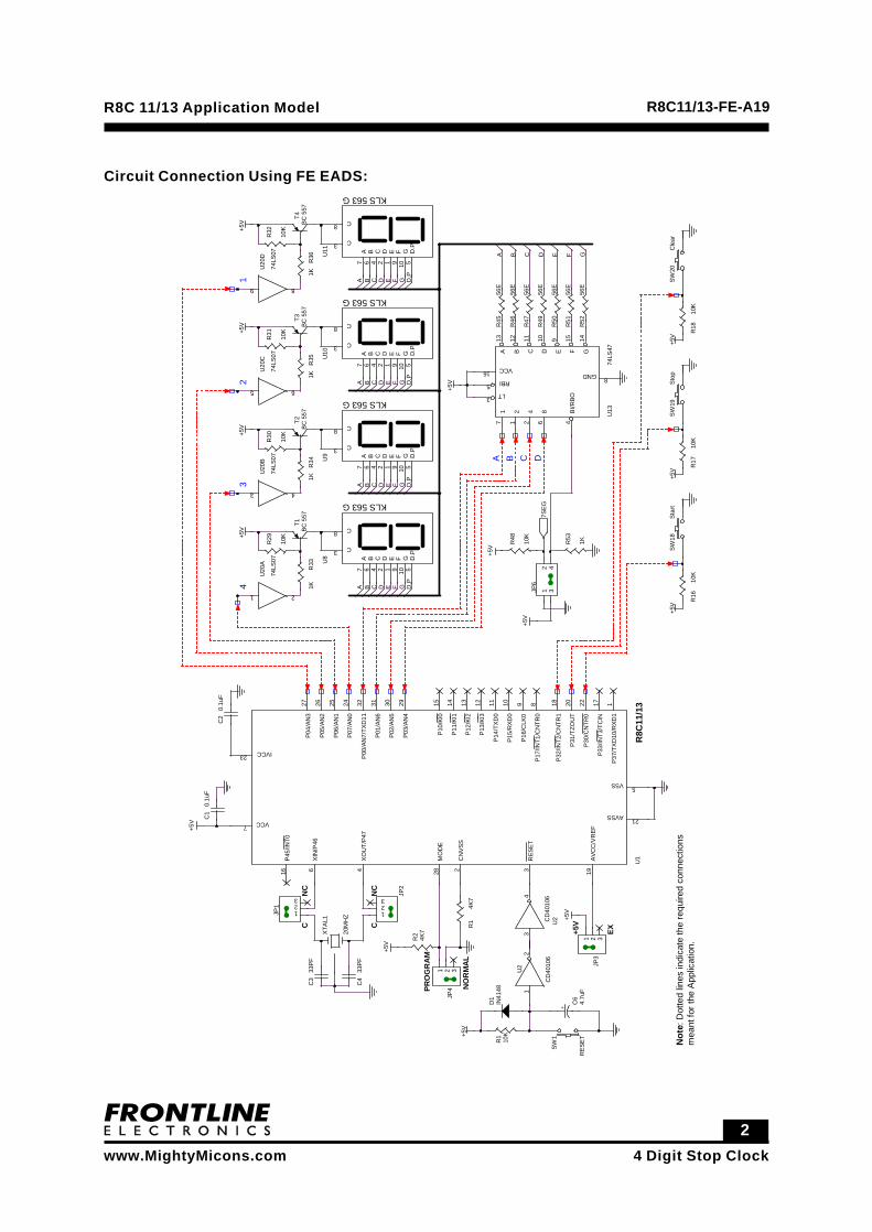
Circuit Connection Using FE EADS:+5
V
+5V
+5V
+5V
+5V
+5V
+5V
+5V
+5V
+5V
+5V
+5V
+5V
+5V
CN
C
NC
C
PRO
GR
AM
NO
RM
AL
+5V
EX
B D
43
21
A C
GD F
C
D.P
D.P
D GFEC D.P
E
C
GFD
GD FE D.P
C E
AA
BAA B
BB
A B C D E F G
0.1u
FC
1
33PF
C4
20M
HZ
XTA
L1
33PF
C3
JP4
1 2 3
IN41
48D
1
CD
4010
6
U2
12
+ 4.7u
FC
6
10K
R1
T4BC
557
R36
1K
U11
KLS 563 G
A7
B6
C4
D2
E1
F9
G10
C8
D.P
5
C3
T3BC
557
R35
1K
U10
KLS 563 G
A7
B6
C4
D2
E1
F9
G10
C8
D.P
5
C3
U9
KLS 563 G
A7
B6
C4
D2
E1
F9
G10
C8
D.P
5
C3
R34
1K
T2B
C 5
57R
331K
T1BC
557
U8
KLS 563 G
A7
B6
C4
D2
E1
F9
G10
C8
D.P
5
C3
R29
10K
R30
10K
R31
10K
R32
10K
U20
A
74LS
07
1 2
U20
B
74LS
07
3 4
U20
C
74LS
07
5 6
U20
D
74LS
07
9 8
R47
56E
R49
56E
R50
56E
R51
56E
R52
56E
R45
56E
R46
56E
U13
74LS
47
17
21
42
86
BI/R
BO4
RBI5LT3
A13
B12
C11
D10
E9
F15
G14
VCC16 GND 8
JP6
12
34
R53
1K
0.1u
FC
2
CD
4010
6U
2
34
R1
4K7
JP2
123
RES
ET
SW1
JP1 1
23
JP3
1 2 3R2
4K7
R48
10K
10K
R16
SW18
Star
t
10K
R17
SW
19St
op
10K
R18
SW20
Cle
ar
R8C
11/1
3U
1
P37/
TXD
10/R
XD1
1
CN
VSS
2
RES
ET3
XO
UT/
P47
4
VSS 5
XIN
/P46
6
VCC7
P17/
INT1
/CN
TR0
8P1
6/C
LK0
9P1
5/R
XD0
10P1
4/TX
D0
11P
13/K
I312
P12
/KI2
13P
11/K
I114
P10
/KI0
15
P45
/INT0
16
MO
DE
28
IVCC23
P30/
CN
TR0
22
AVSS 21
P31
/TZO
UT
20
AVC
C/V
REF
19
P32/
INT2
/CN
TR1
18
P33/
INT3
/TC
IN17
P00
/AN
7/TX
D11
32
P01/
AN6
31
P02/
AN5
30
P03/
AN4
29
P04/
AN3
27
P05/
AN2
26
P06/
AN1
25
P07/
AN0
24
7SE
G
Not
e: D
otte
d lin
es in
dica
te th
e re
quire
d co
nnec
tions
mea
nt fo
r the
App
licat
ion.
34 Digit Stop Clock
R8C 11/13 Application Model R8C11/13-FE-A19
www.MightyMicons.com
Connections:
1. Connect port lines P00 to P03 to BCD inputs of seven segement display.
2. Connect port lines P04 to P07 to digit selection input of seven segment display.
3. Connect port lines P30 to P32 to three push button switches.
Functional Description:
In this module, a complete project for the 4 digit stop clock is provided. 4 digits of seven segment
display are used for displaying the seconds and 3 numbers of push button switches are used to
give Start, Stop and Clear commands. The seven segment display is used in multiplexed mode
with BCD input.
Timer X of the R8C Tiny is used to generate an interrupt at a rate of one milli second. In the timer
X interrupt service routine, the LED display is refreshed and the milli seconds are counted to get
one second delay for counting the seconds after the start command from the user.
Registers Used:
PD0 - Port 0 Direction Register
PD3 - Port 3 Direction Register
TXMR- Timer X mode register
PREX- Prescaler X Register
TX - Timer X Register
TCSS- Timer count source setting register
44 Digit Stop Clock
R8C 11/13 Application Model R8C11/13-FE-A19
www.MightyMicons.com
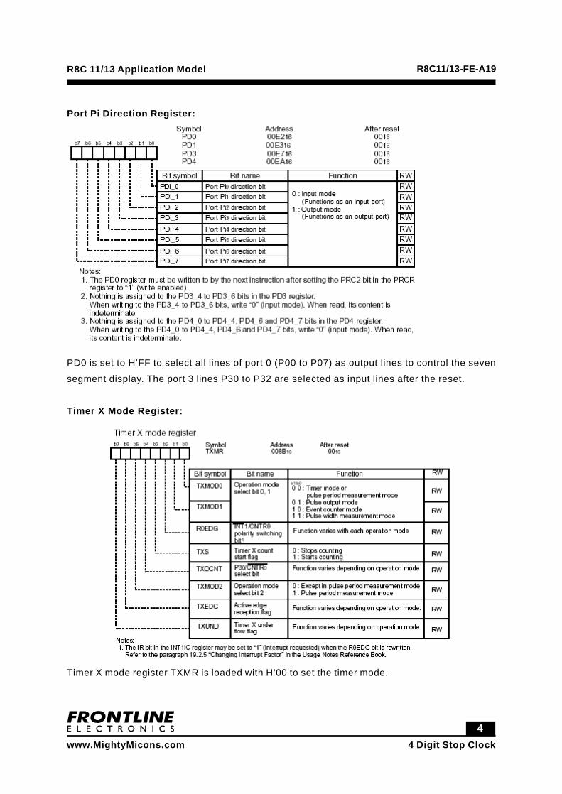
Port Pi Direction Register:
PD0 is set to H’FF to select all lines of port 0 (P00 to P07) as output lines to control the seven
segment display. The port 3 lines P30 to P32 are selected as input lines after the reset.
Timer X Mode Register:
Timer X mode register TXMR is loaded with H’00 to set the timer mode.

54 Digit Stop Clock
R8C 11/13 Application Model R8C11/13-FE-A19
www.MightyMicons.com
Prescalar X Register
The prescaler register PREX is loaded with 100 to divide the selected clock meant for the timer
X.
Timer X Register
The timer X register TX loaded with 100 to generate an interrupt at 1 milli second rate.

64 Digit Stop Clock
R8C 11/13 Application Model R8C11/13-FE-A19
www.MightyMicons.com
Timer Count Source Setting Register.
The data H’03 is moved to Timer Count Source Setting Register TCSS to select “f2” as source
clock for Timer X.
Software Description:
In the main loop, two types of operations are carried out according to the clock status. If the
clock is in active running condition, only stop swicth was enabled during switch scanning to
issue a stop command. In the active stop clock condition, clear command is disabled. When the
clock is stopped, the start and clear switches are enabled to get start and clear commands.
After the start command, the clock running variable is set to clock running state and after the
clear command, the variable holding the seconds count will be cleared to 0.
The files used in this module are listed below:
Files Description
R8C1113_FE_A19.C
The only file for this module, has the processing function for the stop clock, timer X interrupt
service routine and initialization routines for seven segment
display, timer X etc.
74 Digit Stop Clock
R8C 11/13 Application Model R8C11/13-FE-A19
www.MightyMicons.com
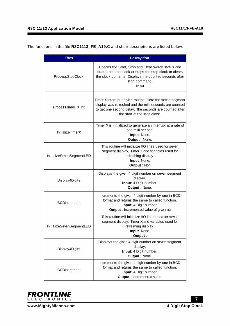
The functions in the file R8C1113_FE_A19.C and short descriptions are listed below:
Files Description
ProcessStopClock
Checks the Start, Stop and Clear switch status and starts the stop clock or stops the stop clock or clears
the clock contents. Displays the counted seconds after start command.
Inpu
ProcessTimer_X_Int
Timer X interrupt service routine. Here the seven segment display was refreshed and the milli seconds are counted to get one second delay. The seconds are counted after
the start of the stop clock.
InitializeTimerX
Timer X is initialized to generate an interrupt at a rate of one milli second.
Input: None. Output : None.
InitializeSevenSegmentLED
This routine will initialize I/O lines used for seven segment display, Timer X and variables used for
refreshing display. Input: None. Output : Non
Display4Digits
Displays the given 4 digit number on seven segment display.
Input: 4 Digit number. Output : None.
BCDIncrement
Increments the given 4 digit number by one in BCD format and returns the same to called function.
Input: 4 Digit number. Output : Incremented value of given nu
InitializeSevenSegmentLED
This routine will initialize I/O lines used for seven segment display, Timer X and variables used for
refreshing display. Input: None.
Output :
Display4Digits
Displays the given 4 digit number on seven segment display.
Input: 4 Digit number. Output : None.
BCDIncrement
Increments the given 4 digit number by one in BCD format and returns the same to called function.
Input: 4 Digit number. Output : Incremented value.
84 Digit Stop Clock
R8C 11/13 Application Model R8C11/13-FE-A19
www.MightyMicons.com
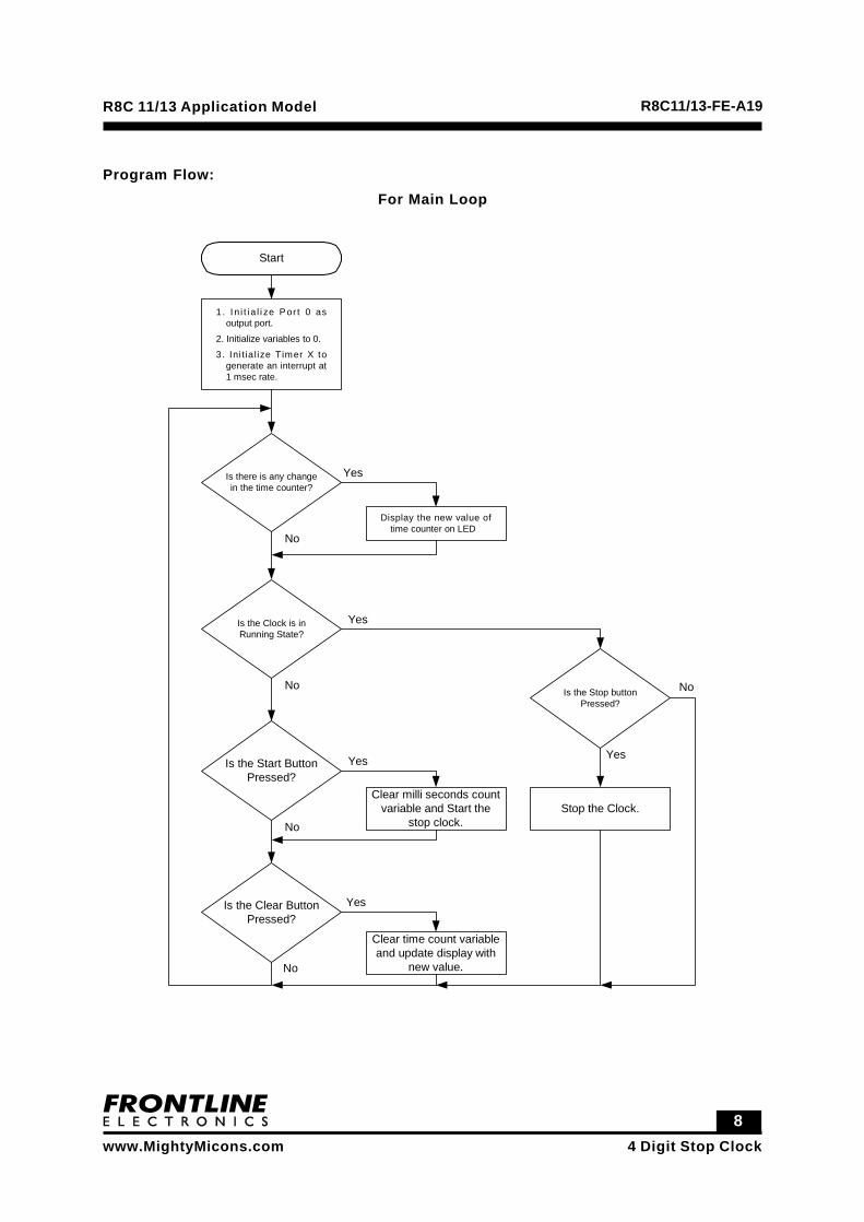
Program Flow:For Main Loop
Start
1. I n i t ia l i ze Por t 0 asoutput port.
2. Initialize variables to 0.
3. Ini t ia lize Timer X togenerate an interrupt at1 msec rate.
Is there is any changein the time counter?
Display the new value oftime counter on LED
Is the Clock is inRunning State?
Yes
No
Yes
NoIs the Stop button
Pressed?
No
YesIs the Start Button
Pressed?Yes
No
Is the Clear ButtonPressed?
Yes
No
Clear milli seconds countvariable and Start the
stop clock.
Clear time count variableand update display with
new value.
Stop the Clock.
94 Digit Stop Clock
R8C 11/13 Application Model R8C11/13-FE-A19
www.MightyMicons.com
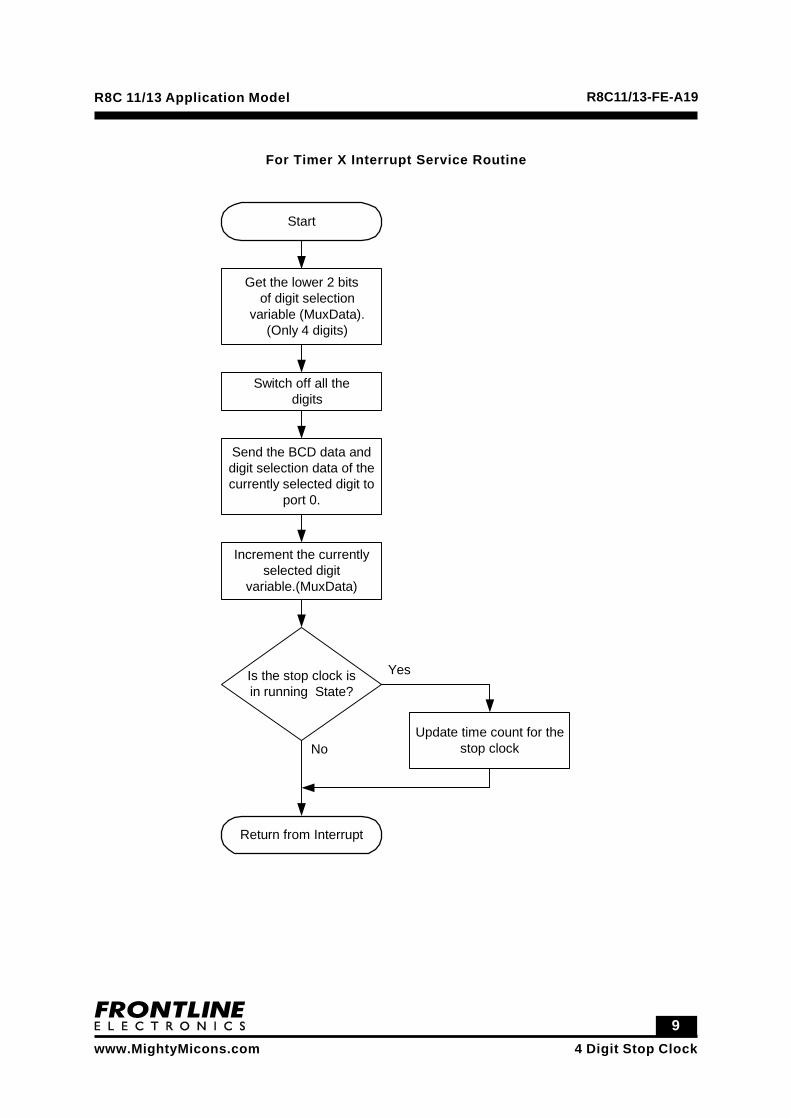
For Timer X Interrupt Service Routine
Start
Get the lower 2 bitsof digit selection
variable (MuxData).(Only 4 digits)
Switch off all thedigits
Send the BCD data anddigit selection data of thecurrently selected digit to
port 0.
Increment the currentlyselected digit
variable.(MuxData)
Is the stop clock isin running State?
Return from Interrupt
No
Yes
Update time count for thestop clock

1 04 Digit Stop Clock
R8C 11/13 Application Model R8C11/13-FE-A19
www.MightyMicons.com
Execute Demo:
After reset, the stop clock starts showing its initial value 0000. The program will wait for start
command from the user. After the start command, the clock will start counting the time and
displayed in four digits from 0000 to 9999 seconds. When the stop button is pressed, the clock
will be stopped and the display will show the current time count. The time count will be cleared
to 0000 if the clear button is pressed when the clock is in stop condition.
1 14 Digit Stop Clock
R8C 11/13 Application Model R8C11/13-FE-A19
www.MightyMicons.com
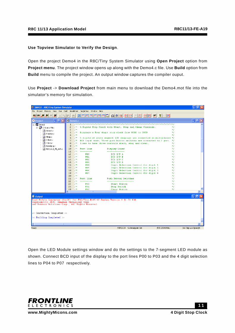
Use Topview Simulator to Verify the Design.
Open the project Demo4 in the R8C/Tiny System Simulator using Open Project option from
Project menu. The project window opens up along with the Demo4.c file. Use Build option from
Build menu to compile the project. An output window captures the compiler ouput.
Use Project -> Download Project from main menu to download the Demo4.mot file into the
simulator’s memory for simulation.
Open the LED Module settings window and do the settings to the 7-segment LED module as
shown. Connect BCD input of the display to the port lines P00 to P03 and the 4 digit selection
lines to P04 to P07 respectively.

1 24 Digit Stop Clock
R8C 11/13 Application Model R8C11/13-FE-A19
www.MightyMicons.com
Open the Keybaord Module settings window and do the settings. Connect the rows to P14 to
P17 and columns to P10 to P13.

1 34 Digit Stop Clock
R8C 11/13 Application Model R8C11/13-FE-A19
www.MightyMicons.com
Then open the LED window usign the option View -> External Modules -> LED as shown
below and the Program Window. Open the Keybaord window usign the option View -> ExternalModules -> Keyboard as shown below and the Program Window.

1 44 Digit Stop Clock
R8C 11/13 Application Model R8C11/13-FE-A19
www.MightyMicons.com
Run the program using Go from the Run menu.
After reset, the stop clock starts showing its initial value 0000. The program will wait for start
command from the user. After the start command, the clock will start counting the time and
displayed in four digits from 0000 to 9999 seconds. When the stop button is pressed, the clock
will be stopped and the display will show the current time count. The time count will be cleared
to 0000 if the clear button is pressed when the clock is in stop condition.