race car aerodynamicsmafija.fmf.uni-lj.si/seminar/files/2007_2008/racecaraer… · ·...
TRANSCRIPT

University of Ljubljana
Faculty of mathematics and physics
Department of physics
Race Car Aerodynamics
Gregor Seljak
May 13, 2008
Mentor: Prof. Dr. Rudolf PodgornikAsist. Dr. Gregor Veble
Abstract
The purpose of this seminar is to describe main aerodynamic principles ofcar racing. In the first part, theoretical solutions for airfoil and finite wingcharacteristics are derived and principle of ground effect is introduced. Inthe second part, practical applications of aerodynamic devices in car racingare described.

Contents
1 Introduction 2
2 Airfoils 2
2.1 Flow over an airfoil . . . . . . . . . . . . . . . . . . . . . . . . 32.2 Thin airfoil theory . . . . . . . . . . . . . . . . . . . . . . . . 42.3 Viscid flow . . . . . . . . . . . . . . . . . . . . . . . . . . . . . 8
3 Finite wings 8
3.1 Prandtl’s classical lifting-line theory . . . . . . . . . . . . . . . 9
4 Ground effect 12
5 Applications in car racing 13
5.1 Rear wing . . . . . . . . . . . . . . . . . . . . . . . . . . . . . 135.2 Front wing . . . . . . . . . . . . . . . . . . . . . . . . . . . . . 145.3 Underbody . . . . . . . . . . . . . . . . . . . . . . . . . . . . 17
6 Conclusion 19
1

1 Introduction
First racing cars were primarily designed to achieve high top speeds and themain goal was to minimize the air drag. But at high speeds, cars developedlift forces, which affected their stability. In order to improve their stabilityand handling, engineers mounted inverted wings profiles1 generating negativelift. First such cars were Opel’s rocket powered RAK1 and RAK2 in 1928[1].However, in Formula, wings were not used for another 30 years. Racing inthis era occured on tracks where the maximum speed could be attained oversignificant distance, so development aimed on reducing drag and potencial ofdownforce had not been discovered until the late 1960’s[2]. But since then,Formula 1 has led the way in innovative methods of generating downforcewithin ever more restrictive regulations.
Figure 1: Opel’s rocket powered RAK2, with large side wings
2 Airfoils
Airfoil can be defined as a shape of wing, as seen in cross-section. In orderto describe an airfoil, we must define the following terms[3](Figure 2)
• The mean camber line is a line drawn midway between the upper andlower surfaces.
• The leading and trailing edge are the most forward an rearward of themean camber line.
1Compared to an aircraft
2

• The chord line is a line connecing leading an trailing edge.
• The chord length is the distance from the leading to the trailing edge,measured along the chord line.
• The camber is the maximum distance between mean camber line andchord line.
• The thickness is the distance between the upper and lower surfaces.
Figure 2: Airfoil nomenclature
The amount of lift L produced by the airfoil, can be expressed in term of lift
coefficient CL
L =1
2ρ∞V
2
∞SCL (1)
where V∞ denotes the freestrem velocity, ρ∞ fluid density and S the airfoilarea.
2.1 Flow over an airfoil
Properties of an airfoil can be measured in a wind tunnel, where constant-chord wing spannes the entire test section, from one sidewall to the other.In this conditions, the flow sees a wing without wing tips. Such wing iscalled infinite wing and streches to infinity along the span. Because theairfoil section is identical along the wing, the properties of the airfoil and theinfinite wing are identical. Therefore the flow over an airfoil can be describedas a 2D incompressible inviscid flow over an infinite wing[3].
Lift per unit span L′ generated by an arbitrary airfoil(or any other body)moving at speed V∞ through the fliud with density ρ∞ and circulation Γ is
3

given by Kutta-Joukowsky theorem[3]
L′ = ρ∞V∞Γ . (2)
Circulation around an airfoil, can be calculated with the concept of a vortexsheet, which was first introduced by Prandtl an his colleagues. Consider anairfoil of arbitrary shape and thickness as shown in Figure 3. Circulation canbe distributed over the whole airfoil area with surface density(vortex sheetstrength) dΓ/ds = γ(s), where γ(s) must satisfy Kutta condition[3]
γ(trailing edge) = 0 (3)
Entire circulation is then given by
Γ =∫
γ(s)ds , (4)
where the integral is taken around the complete surface of the airfoil. How-ever, there is no general solution for γ(s) for an airfoil of arbitrary shapeand it must be found numericaly, but analytical solutions can be found withsome aproximations.
Figure 3: Simulation of an arbitrary airfoil by distributing a vortex sheetover the airfoil surface.
2.2 Thin airfoil theory
Here we discuss thin airfoil in freestream of velocity V∞ under small angleof attack α. Camber and thickness are small in relation with chord length c.In such case, airfoil can be described with a single vortex sheet distributedover the camber line(Figure 4). Our goal is to calculate the variation ofγ(s), such that the chamber line becomes streamline and Kutta condition attrailing edge, γ(c) = 0, is satisfied.
4

Figure 4: Thin airfoil approximation. Vortex sheet is distributed over thechamber line
The velocity at any point in the flow is the sum of the uniform freestreamvelocity and velocity induced by the vortex sheet . In order the camber lineto be a streamline, the component of velocity normal to the camber line mustbe zero at any point along the camber line.
w′(s) + V∞,n = 0 , (5)
where w′(s) is the component of velocity normal to the chamber line inducedby the vortex sheet and V∞,n the component of the freestrem velocity normalto the camber line. Considering small angle of attack2 and defining β(x) =dz/dx as the slope of the chamber line, V∞,n can be written as (Figure 5)
V∞,n = V∞(
α−dz
dx
)
(6)
Because airfoil is very thin, we can make the approximation
w′(s) ≈ w(x) , (7)
where w(x) denotes the component of velocity normal to the chord line andcan be, using the Biot-Savart law[4], expressed as
w(x) = −∫ c
0
γ(ξ)dξ
2π(x− ξ)(8)
Substituting equations (6), (7) and (8) into (5) and considering Kutta con-dition, we obtain
1
2π
∫ c
0
γ(ξ)dξ
x− ξ= V∞
(
α−dz
dx
)
γ(c) = 0 (9)
2tan−1α ≈ α
5

Figure 5: Determination of the component of freestrem velocity normal tothe chamber line
fundamental equations of thin airfoil theory.In order to satisfy this conditions , we first transform our variables x and
ξ into [3]
ξ =c
2(1− cos θ) x =
c
2(1− cos θ0) (10)
and equation (9) becomes
1
2π
∫ π
0
γ(θ) sin θdθ
cos θ − cos θ0= V∞
(
α−dz
dx
)
(11)
with a solution that satisfies Kutta condition γ(π) = 0
γ(θ) = 2V∞(
A0
1 + cos θ
sin θ+∞∑
n=1
An sin(nθ))
(12)
In order to find coefficients A0 and An, we substitute equation (12) intoequation (11) and use the following trigonometric relations[3]
∫ π
0
sin(nθ) sin θdθ
cos θ − cos θ0= −π cos(nθ0) (13)
∫ π
0
cos(nθ)dθ
cos θ − cos θ0=π sin(nθ0)
sin θ0(14)
6

and finally obtain
dz
dx= (α− A0) +
∞∑
n=1
An cos(nθ0) (15)
This equation is in form of a Fourier cosine series expansion for the functiondz/dx. Comparing it to the general form for the Fourier cosine expansion weobtain
A0 = α−1
π
∫ π
0
dz
dxdθ0 (16)
An =2
π
∫ π
0
dz
dxcos(nθ0)dθ0 (17)
The total circulation due to entire vortex sheet from leading to the trailingedge is
Γ =∫ c
0
γ(ξ)dξ =c
2
∫ c
0
γ(θ) sin θ dθ (18)
Substituting equation (12) for γ(θ) into equation (18) and carrying out theintegration, we obtain
Γ = cV∞(
πA0 +π
2A1
)
(19)
hence the lift per unit span, given by Kutta-Joukowski is
L′ = ρ∞V∞Γ = cρ∞V2
∞
(
πA0 +π
2A1
)
(20)
This equation leads to the lift coefficient in form
cl = π(2A0 + A1) = 2π[
α +1
π
∫ π
0
dz
dx(cos(nθ0)− 1)dθ0
]
(21)
and lift slope
lS ≡dcldα
= 2π (22)
Last two results are important. We can see, that lift coefficient is func-tion of the shape of the profile dz/dx and angle of attack α, and that evensymmetrical wing produces lift, when set under an angle of attack. Lift slopeis constant, independently of the shape of the profile, while the zero lift angle
αL=0 = −1
π
∫ π
0
dz
dx
(
cos(nθ0)− 1)
dθ0 (23)
depends on the shape. The more highly chambered the airfoil, the larger isαL=0
7
2.3 Viscid flow
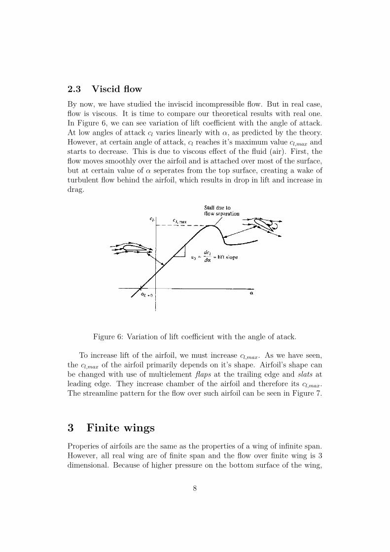
By now, we have studied the inviscid incompressible flow. But in real case,flow is viscous. It is time to compare our theoretical results with real one.In Figure 6, we can see variation of lift coefficient with the angle of attack.At low angles of attack cl varies linearly with α, as predicted by the theory.However, at certain angle of attack, cl reaches it’s maximum value cl,max andstarts to decrease. This is due to viscous effect of the fluid (air). First, theflow moves smoothly over the airfoil and is attached over most of the surface,but at certain value of α seperates from the top surface, creating a wake ofturbulent flow behind the airfoil, which results in drop in lift and increase indrag.
Figure 6: Variation of lift coefficient with the angle of atack.
To increase lift of the airfoil, we must increase cl,max. As we have seen,the cl,max of the airfoil primarily depends on it’s shape. Airfoil’s shape canbe changed with use of multielement flaps at the trailing edge and slats atleading edge. They increase chamber of the airfoil and therefore its cl,max.The streamline pattern for the flow over such airfoil can be seen in Figure 7.
3 Finite wings
Properies of airfoils are the same as the properties of a wing of infinite span.However, all real wing are of finite span and the flow over finite wing is 3dimensional. Because of higher pressure on the bottom surface of the wing,
8

Figure 7: Flow over multielement airfoil.
the flow tends to leak around the wing tips. This flow establishes a circularymotion that trails downstream of the wing. A trailing vortex is created ateach wing tip. These wing-tip vortices induce a small downward componentof air velocity, called downwash . It produces a local relative wind whichis directed downward in the vicinity of the wing, and reduces the angle ofattack that each section of the wing effectively sees
αeff = α− αi (24)
and it creates a component of drag, defined as induced drag.
3.1 Prandtl’s classical lifting-line theory
The idea of lifting line theory, is to use two dimensional results, and correctthem for the influence of the trailing vortex wake and its downwash[5]. Let’sreplace a finite wing of span b, with a bound vortex3 extending from y = −b/2to y = b/2. But due to the Helmholtz’s theorem[3], a vortex filament can’tend in a fluid. Therefore assume the vortex filament continues as two freevortices trailing downstream from the wing tips to infinity(Figure 8). Thisvortex is, due to it’s shape, called horseshoe vortex. Downwash inducedby such vortex, does not realistically simulate that of a finite wing, as itaproaches −∞ at wing tips[3].
Instead of representing the wing by a single horseshoe vortex, Prandtl su-perimposed an infinite number of horseshoe vortices, each with an infinites-imally small strength dΓ, and with all the bound vortices coincident along
3A vortex bound to a fixed location in flow
9

Figure 8: Replacement of the finite wing with single horseshoe vortex.
a single line, called the lifting line. In this model, we have a continious dis-tribution of circulation Γ(y) along the lifting line with the value Γ0 at theorigin. The two trailing vortices in single horseshoe vortex model, have now
Figure 9: Superposition of an infinite number of horseshoe vortices along thelifting line.
became a continious vortex sheet trailing downstream of the lifting line, andthe total downstream velocity w, induced at the coordinate y0 by the entiretrailing vortex sheet can be expressed as
w(y0) = −1
4π
∫ b/2
−b/2
(dΓ/dy)dy
y0 − y(25)
The induced angle of attack at the arbitrary spanwise location y0 is given by
αi(y0) = arctan(−w(y0)
V∞
)
=−w(y0)
V∞, (26)
10

where we considered V∞ ≫ w(y0) and arctan(α) ≈ α for small values of α.Now we can obtain an expression for the induced angle of attack in term ofthe circulation distribution along the wing
αi(y0) = −1
4πV∞
∫ b/2
−b/2
(dΓ/dy)dy
y0 − y(27)
Combining results
cl =2Γ(y0)
V∞(28)
andcl = 2π[αeff(y0)− αL=0] (29)
for coefficient of lift per unit span from thin airfoil theory, we obtain
αeff =Γ(y0)
πV∞c(y0)+ αL=0 (30)
Substituting equations (27) and (30) into (24), we finally obtain the funda-mental equation of Prandtl’s lifting line theory[3].
α(y0) =Γ(y0)
πV∞c(y0)+ αL=0(y0) +
1
4πV∞
∫ b/2
−b/2
(dΓ/dy)dy
y0 − y(31)
Just as in thin airfoil theory, this integral equation can be solved by assuminga Fourier series representation for the distribution of vorticity
Γ(Θ) = 2bV∞N∑
n=1
An sin nΘ (32)
where we considered transormation y = (−b/2) cos Θ, with 0 ≤ Θ ≤ π andcoefficients An must satisfy Equation (31). With such vorticity distribution,Equation (31) becomes
α(Θ0) =2b
πc(Θ0)
N∑
n=1
An sin nΘ0 + αL=0(Θ0) +N∑
n=1
nAnsin nΘ0
sin Θ0
(33)
The total lift distribution is obtained by integrating equation for lift distri-bution over the span
L =∫ b/2
−b/2ρ∞V∞Γ(y)dy (34)
Coefficients of lift and induced drag4, can be calculated via equations
CL =L
q∞S=
2
V∞S
∫ b/2
−b/2Γ(y)dy (35)
4Note the difference in nomenclature. In 2D case, coefficients have been denoted with
lowercase letters-cl, cd. In 3D case, we use capital letters-CL, CD
11

and
CD =D
q∞S=
2
V∞S
∫ b/2
−b/2αi(y)Γ(y)dy (36)
respecteviliy. Considering expressions (32) and (33), they can be written as
CL = A1πAR (37)
and
CD,i =C2
L
πAR(1 + δ) (38)
where AR is aspect ratio of finite fing, defined as AR = b2/S, and δ =∑N
2(An/A − 1)2. Note that CL depends only on the leading coefficient in
Fourier series expansion and that δ ≥ 0. Therefore, the lowest induced dragwill be produced by a wing where δ = 0, that is, n = 1. Such circula-tion distribution is given by Γ(Θ) = 2bV∞A1 sin Θ and is known as elliptical
circulation distribution.
4 Ground effect
The main differece between wing application in aviation and car racing is,that cars are in contact with the ground. Therefore, wing experiences someadditional effects due to ground proximity. Remember the wing tip vorticeswe mentioned at the beginning of the previous section. They do nothingbut harm, as they increase drag and decrease lift at given angle of attack.When flying near to the ground, the ground partially blocks(Figure 10) thetrailing vortices and decreases the amount of downwash generated by thewing[6]. This reduction in downwash increases the effective angle of attackof the wing so that it creates more lift and less drag than it would otherwise.This effect is greater, the closer to the ground the wing operates.
Figure 10: Effect of the ground proximity on creation of the trailing vortices.
Another way to create downforce is to create low pressure area underneaththe car, so that the higher pressure above the car will apply a downward
12

force. The area between car’s underbody and the ground, can be thougthas an example of Venturi nozzle[1]. The Venturi effect may be derived froma combination of Bernoulli’s principle and the equation of continuity. Thefluid velocity increases through the constriction to satisfy the equation ofcontinuity, while it’s pressure decreases due to conservation of energy. Thegain in kinetic energy is supplied by a drop in pressure. The main advantageof ground effect is, that it produces almost no drag.
5 Applications in car racing
Now summarize what we have learned so far. The coefficient of lift increaseswith increasing angle of attack. At some angle, flow seperates from the wing,which causes drop of lift coefficient. With use of multidimensional flaps, weincrease chamber of the airfoil and thus maximum coefficent of lift.
In 3 dimensional case, vortices appear at wing tips. They reduce wing’sefficiency and increase drag. The lowest drag can be achieved with ellipticallyshaped wing. Dimensions of the wing are also important. Wing with greatersurface, produces more lift and wing with higher aspect ratio induces less airresistance.
In the next sections, we will see, how engineers used this principles atdeveloping the main aerodynamical parts of racing cars.
5.1 Rear wing
First rear wing appeared in 1966[1], when Jim Hall equiped his Chaparral2E with a rear wing. From then on, use of wings grew quickly. First wingswere mounted high over the rear end of the car to operate in indisturbedflow. They were also mounted on pivots, so the driver was able to changethe angle of attack during the ride. High mounted wings often broke offduring the race and were therefore prohibited by FIA. In Formula 1, wingswere first introduced in 1968 at the Belgium grand prix[7], when Ferrari usedfull inverted rear wings, and Brabham did likewise, just one day after theFerrari’s wings first appeared.
Modern rear wings produce approximately 30-35 % of the total down-force of the car[2]. A typical configuration(Figure 12) consists of two sets ofairfoils connected to each other by the wing endplates. The most downforceis provided by the upper airfoil. To achieve the greatest possible lift coeffi-cient, it consists of multiple high aspect ratio elements, which prevent flowseparation. Angle of attack depends on circuit configuration. On tracks withmany turns, more downforce is needed, therefore the wing is set at higher
13

Figure 11: Chaparral 2E (left) and Ferrari 312 (right).
angle of attack. Conversely, on tracks with long straights, wing has smallangle attack, thus reducing air drag and allowing higher top speeds. Lowerairfoil section actually reduces the downforce produced by total rear wing,but it creates a low-pressure region just below the wing to help the diffuser5
to create more downforce below the car. Ususally it consists of two elements.Another important part of rear wing are endplates . They provide a con-
venient way of mounting wings, but also have aerodynamic function. Theyreduce the 3D effect of the wing by preventing air leakage around the wingtips and thus formation of trailing vortices. An additional goal of the rearendplates is to help reduce the influence of upflow from the rear wheels.The U-shaped cutout from the endplate further alleviates the developmentof trailing vortices.
5.2 Front wing
The front wing on the car produces 25-30% of the car’s downforce[2] and ithas experienced more modifications than rear wing. It is the first part ofthe car to meet the air mass, therefore, besides creating downforce, it’s maintask is to efficiently guide the air towards the body and rear of the car, asthe turbulent flow impacts the efficiency of the rear wing.
Front wings appeared in Formula 1 just two weaks after the first rearwings, on Lotus 49B[9]. First front wings were quite simple with singlerectangular airfoil with flat vertical endplates to reduce wing tip vortices.First improvement appeared in 1971, with so-called Gurney flap[9]. Thisis a flat trailing edge flap perpendicular to the chord and projects no morethan 5% of the chord. It can improve the performance of a simple airfoil tonearly the same level as a complex design. The same year, the concept of
5See section 5.3
14

Figure 12: Modern rear wing consists of upper(1) an lower(2) airfoil sectionmounted on endplates (3) with U-shaped cutout (4).
Figure 13: Configuration of modern front wing. Two element airfoil (1 & 2)is mounted under the nose of the car (3). Endplates (4) direct air aroundthe wheels and curved area (5) under the nose increases wing’s efficiency.
elliptical wing was applied. March equiped it’s 711 with elliptical front wing.Two years later Ferrari avoided wing-body interaction with wing mountedquite far ahead from the body. Multi element wings were introduced in 1984by McLaren[9]. The angle of attack of the second element was allowed to
15

be modified so that the load applied on the front wing could be changedto balance the car according to the driver’s wishes. In 1990 Tyrell raisedthe nose of it’s 019 to increase the flow under the nose cone and improveflow conditions under the car[9]. This concept avoids wing-body interactionand allows the front wing to operate in undisturbed flow. It also enlargeseffective area of the wing. After Imola 1994, the FIA regulations do notallow any chassis parts under a minimum ground height. This clearance isdifferent between the centre and the side of the car[9]. Teams used this tocurve front wing in the centre of the span and regain some of the lost groundeffect. In 1998, regulations decreased the width of Formula 1 car, so the frontwings overlapped the front wheels. This created unnecessary turbulence infront of the wheels and reducing aerodynamic efficiency of the wing. Withreducing wing’s span this could be avoided, but it would also decrease wing’saspect ratio. Instead of this, teams use wing tips to direct the air around thewheels[9].
Figure 14: Some historical milestones in front wing development. Lotus 49B,March 711, Ferrari 312 B3 and Tyrrell 019.
16
5.3 Underbody
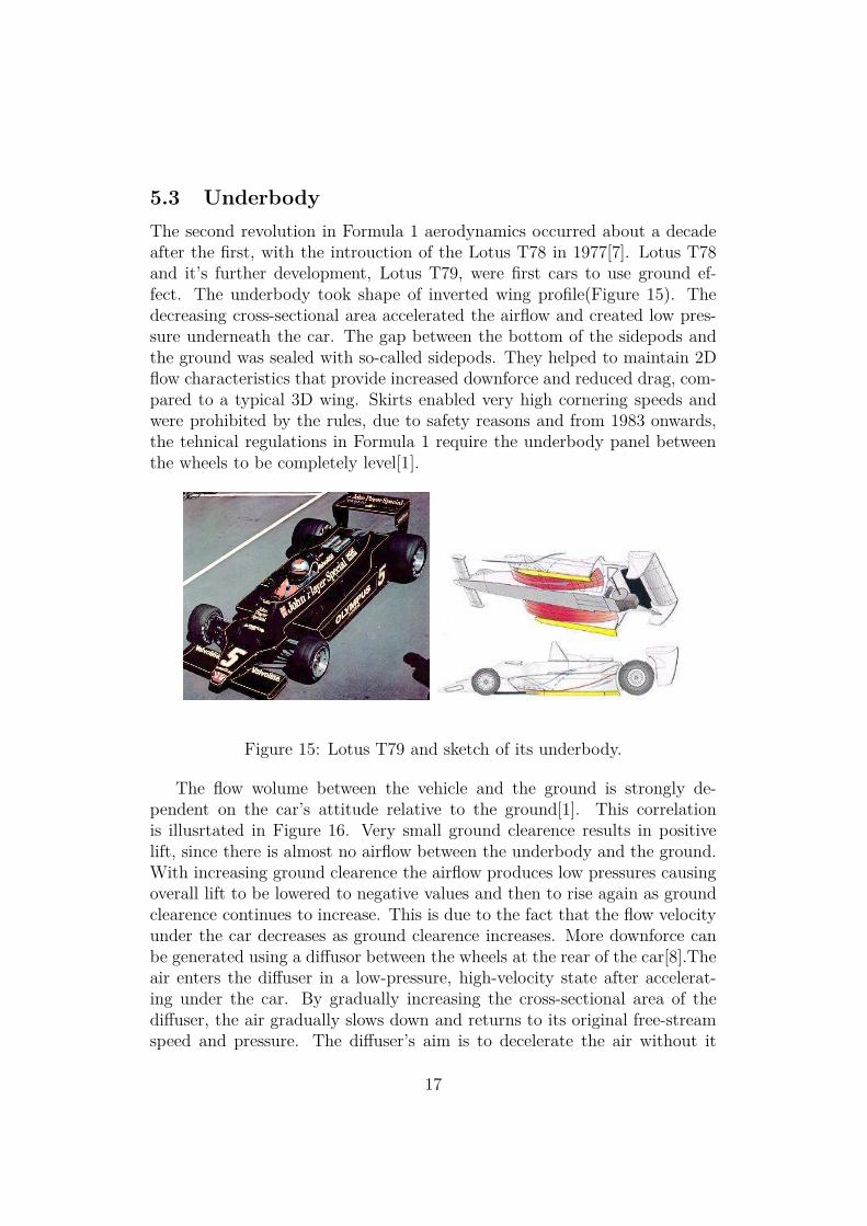
The second revolution in Formula 1 aerodynamics occurred about a decadeafter the first, with the introuction of the Lotus T78 in 1977[7]. Lotus T78and it’s further development, Lotus T79, were first cars to use ground ef-fect. The underbody took shape of inverted wing profile(Figure 15). Thedecreasing cross-sectional area accelerated the airflow and created low pres-sure underneath the car. The gap between the bottom of the sidepods andthe ground was sealed with so-called sidepods. They helped to maintain 2Dflow characteristics that provide increased downforce and reduced drag, com-pared to a typical 3D wing. Skirts enabled very high cornering speeds andwere prohibited by the rules, due to safety reasons and from 1983 onwards,the tehnical regulations in Formula 1 require the underbody panel betweenthe wheels to be completely level[1].
Figure 15: Lotus T79 and sketch of its underbody.
The flow wolume between the vehicle and the ground is strongly de-pendent on the car’s attitude relative to the ground[1]. This correlationis illusrtated in Figure 16. Very small ground clearence results in positivelift, since there is almost no airflow between the underbody and the ground.With increasing ground clearence the airflow produces low pressures causingoverall lift to be lowered to negative values and then to rise again as groundclearence continues to increase. This is due to the fact that the flow velocityunder the car decreases as ground clearence increases. More downforce canbe generated using a diffusor between the wheels at the rear of the car[8].Theair enters the diffuser in a low-pressure, high-velocity state after accelerat-ing under the car. By gradually increasing the cross-sectional area of thediffuser, the air gradually slows down and returns to its original free-streamspeed and pressure. The diffuser’s aim is to decelerate the air without it
17

separating from the tunnel walls, which would cause a stall, reducing thedownforce and inducing a large drag force. By installing an inverted wingclose to the diffuser exit 6 it is possible to create a low-pressure area, whichessentially sucks the air from the diffuser. The diffuser and wing combina-tion permits a higher air mass flow rate through the diffuser, thus resulting inhigher downforce. Sharp edges on the vertical tunnel walls generate vorticesfrom entrained air and help confine the air through the diffuser and reducethe chance it will separate.
Figure 16: Correlation between lift coefficient and ground clearence(left) anddiffuser on Ferrari F430(right).
Again Chaparral, showed completely new way to create downforce. TheChaparral 2J in 1969 used two rear fans to suck in air from under the car,thus creating low pressure under the car[1]. Big advantage of this conceptis, that downforce can be generated independently of the speed. Fans werealso used in Formula 1. Brabham BT46 used a rear mounted fan driven offthe gearbox. It won it’s debut race in 1978, but was promptly banned by thegoverning body.
Barge boards were first seen in 1993 and their purpose is to smooththe airflow around the car and into the radiator intakes. They are mostcommonly mounted between the front wheels and the sidepods (Figure 18).Their main purpose is to direct relatively clean air into the sidepods.Cleanair is from the low section of the front wing where airflow is fairly unaffectedby the wing and far away from tires, which may throw stones and debris into the radiator. Bargeboards also produce vortices to seal the area betweenthe sidepots and the surface, so they work as a substitude for skirts.
6See rear wing section
18

Figure 17: Two cars which used fans to create downforce. The Chaparral 2J"sucker car" (left) and Brabham BT46 "fan car" (right).
Figure 18: Bargeboards on McLaren MP4/8.
6 Conclusion
Nowadays all calculations are made numerically using sophisticated CFD7
software and half- or full-scale car models are tested in wind tunnels. Atdesigning cars, engineers must satisfy technical regulation set by FIA, whichtries to make racing safe for all participants. In its early years, F1 was verydangereous sport. For drivers and also for spectators, as very litle had beendone for their safety. But thanks to more and more restrictive regulations,there has not been any severe accident since 1994. Now the main problem isattractiveness of races, as we see few overtakings and duels between drivers.
7Computational Fluid Dynamics
19

For the next season FIA applied some new regulations, as reintroduction ofslick tyres and driver-adjustable front wing[10], which could make races morespectacular, and we can hope to see some duels like in old days[11].
References
[1] W. H. Hucho, Aerodynamics of Road Vehicles, 4th edition (Warrendale:Society of Automotive Engineers, 1998)
[2] Peter Wright, Formula 1 Technology (Warrendale: Society of Automo-tive Engineers,2001)
[3] J. D. Anderson, Fundamentals of Aerodynamics (Boston: McGraw-Hill,2001)
[4] Applied Aerodynamics: A Digital Textbook,http://www.desktopaero.com/appliedaero/airfoils1/tatderivation.html
[5] Applied Aerodynamics: A Digital Textbook,http://www.desktopaero.com/appliedaero/potential3d/liftingline.html
[6] Ground Effect and WIG Vehicleshttp://www.aerospaceweb.org/question/aerodynamics/q0130.shtml
[7] Gordon McCabe, Explanation And Discovery In Aerodynamics,arXiv:physics/0512224v1 (2008)
[8] Symscape,http://www.symscape.com/blog/f1_aero
[9] F. Mortel: Cranfield Team F1: The Front Wing,http://www.carbodydesign.com/detail.php?id=710 (2003)
[10] http://www.autosport.com/news/report.php/id/67029
[11] http://www.youtube.com/watch?v=LzCqY8Wg5So
20