raceway solutionstm - information solutions & … · 2009-03-28 · raceway solutions tm 4...
TRANSCRIPT

Raceway SolutionsTM
Conventional Underfloor Duct
Casino Duct
Flush Activation Duct
Trench Duct
Wall Duct
In-Floor Wire Management Systems

Raceway Solutions In-floor Wire Management Systems
Applications• Commercial Buildings
• Retail Facilities
• Office Buildings
• Casinos
• Schools and Universities
• Medical Facilities including X-Ray and MRI Rooms
Features and Benefits• Five Labor Saving Designs
• Systems include a complete line of accessories and fittings
for design flexibility
• Unique one-piece multi-compartment duct reduces
installation labor
• Package and ship by room, area, or floor
• Custom sizes available

c2005 Filges www.filgesco.com
The Power of Intelligent DesignRaceway Solutions Underfloor Duct Systems offer maximum flexibility in designing or building in-slab raceway systems for distribution of power, voice and data conductors. Our Conventional,Casino, Flush Activation, Trench Underfloor, and Wall Duct Systems provide a range of distinct ben-efits, depending on chosen application. There are many potential uses for the wide variety of prod-ucts shown in this catalog. Your local representative will assist you in selecting the appropriate com-bination of systems for your project and provide any additional information required to help youcomplete your job.
Raceway SolutionsTM
Conventional Underfloor Duct Pgs. 2-11
Raceway SolutionsTM
Flush Activation Duct Pgs. 12-18
Raceway SolutionsTM
Casino Underfloor Duct Pgs. 19-23
Raceway SolutionsTM
Trench Duct Pgs. 24-34
Raceway SolutionsTM
Wall Duct Pgs. 35-45

Conventional Underfloor Duct
c2005 Filges www.filgesco.com2
Multi-Compartment Conventional Duct Saves Time andMoney in Your In-Slab Wire Management SystemThe Raceway Solutions Conventional Underfloor Duct System is an in-slab wiremanagement product for delivering power, voice and data services tonumerous point of sale locations or office workstations. The Raceway SolutionsConventional Underfloor Duct System is uniquely designed with multiplecompartments, allowing unlimited design options and fantastic cost savingsin labor and materials from other single-compartment systems.
Here is how Raceway Solutions Conventional Underfloor Duct works for you:• Five designs available, providing the most complete offering in the
industry.• Multi-compartment duct, drastically reducing installation and material costs.
• Four insert heights, expanding the design options of 1", 1½", 2" and 3" sizes.• Inclusive tile trim in the junction box, providing the installer the on-site
option of using the trim or leaving it recessed.• Combination duct couplers and supports, reducing material and labor
costs using the same part for two functions.• Meets or exceeds UL 884 specifications, assuring a fully approved system
from one manufacturer.
Matched with our strong national distribution and complete technical andapplications support, the Raceway Solutions Conventional Underfloor Duct sys-tem is the perfect solution for your underfloor wire management needs, and atan affordable price. As a part of our complete wire management and compo-nents offering, Raceway Solutions Conventional Underfloor Duct is perfect for:• Supermarkets • Office Buildings• Retail Facilities • Airports• Casinos • Institutional Facilities
Raceway SolutionsTM
Catalog Number System
203 - 2 - 12
# of Cells Insert Height Insert Spacing1 = Single Cell B = Blank2 = Two Cell 1 = 1” Height 12 & 24 Standard3 = Three Cell 15 = 1½” Height 6, 18, & 36 (optional)4 = Four Cell 2 = 2” Height
3 = 3” Height

Raceway SolutionsTM
c2005 Filges www.filgesco.com3
Standard Single Compartment DuctCat.No. Duct Width Duct Depth Insert Spacing
201-B ¼" 1½" No Inserts
201-3-24 ¼" 1½" 3" High Inserts 24"o.c.
201-2-24 3¼" 1½" 2" High Inserts 24"o.c.
201-15-24 3¼" 1½" 1½" High Inserts 24" o.c.
201-1-24 3¼" 1½" 1" High Inserts 24" o.c.
201-3-12 3¼" 1½" 3" High Inserts 12" o.c.
201-2-12 3¼" 1½" 2" High Inserts 12" o.c.
201-15-12 3¼" 1½" 1½" High Inserts 12" o.c.
201-1-12 3¼" 1½" 1" High Inserts 12" o.c.
Material: 14 gauge pre-galvanized steel with 668 coating Presets: Die-cast zincUL Listing No.884
Wide Single Compartment DuctCat.No. Duct Width Duct Depth Insert Spacing
201W-B 5⅞" 1½" No Inserts
201W-3-24 5⅞" 1½" 3" High Inserts 24" o.c.
201W-2-24 5⅞" 1½" 2" High Inserts 24" o.c.
201W-15-24 5⅞" 1½" 1½" High Inserts 24" o.c.
201W-1-24 5⅞" 1½" 1" High Inserts 24" o.c.
201W-3-12 5⅞" 1½" 3" High Inserts 12" o.c.
201W-2-12 5⅞" 1½" 2" High Inserts 12" o.c.
201W-15-12 5⅞" 1½" 1½" High Inserts 12" o.c.
201W-1-12 5⅞" 1½" 1" High Inserts 12" o.c.
Material: 14 gauge pre-galvanized steel with 668 coating Presets: Die-cast zincUL Listing No.884
Standard Two Compartment DuctCat.No. Duct Width Duct Depth Insert Spacing Compartment Width
202-B 10" 1½" No Inserts 2 @ 5"
202-3-24 10" 1½" 3" High Inserts 24" o.c. 2 @ 5"
202-2-24 10" 1½" 2" High Inserts 24" o.c. 2 @ 5"
202-15-24 10" 1½" 1½" High Inserts 24" o.c. 2 @ 5"
202-1-24 10" 1½" 1" High Inserts 24" o.c. 2 @ 5"
202-3-12 10" 1½" 3" High Inserts 12" o.c. 2 @ 5"
202-2-12 10" 1½" 2" High Inserts 12" o.c. 2 @ 5"
202-15-12 10" 1½" 1½" High Inserts 12" o.c. 2 @ 5"
202-1-12 10" 1½" 1" High Inserts 12" o.c. 2 @ 5"
Material: 14 gauge pre-galvanized steel with 668 coating Presets: Die-cast zincUL Listing No.884
For different compartment spacing consult factory.
Conventional Underfloor Duct

Raceway SolutionsTM
c2005 Filges www.filgesco.com4
Standard Three Compartment DuctCat.No. Duct Width Duct Depth Insert Spacing Compartment Width
203-B 15" 1½" No Inserts 2 @ 4" – 1 @ 6¾"
203-3-24 15" 1½" 3" High Inserts 24" o.c. 2 @ 4" – 1 @ 6¾"
203-2-24 15" 1½" 2" High Inserts 24" o.c. 2 @ 4" – 1 @ 6¾"
203-15-24 15" 1½" 1½" High Inserts 24" o.c. 2 @ 4"– 1 @ 6¾"
203-1-24 15" 1½" 1'' High Inserts 24" o.c. 2 @ 4"– 1 @ 6¾"
203-3-12 15" 1½" 3" High Inserts 12" o.c. 2 @ 4"– 1 @ 6¾"
203-2-12 15" 1½" 2" High Inserts 12" o.c. 2 @ 4"– 1 @ 6¾"
203-15-12 15" 1½" 1½" High Inserts 12" o.c. 2 @ 4"– 1 @ 6¾"
203-1-12 15" 1½" 1" High Inserts 12" o.c. 2 @ 4"– 1 @ 6¾"
All duct standard 10' lengths.Material: 14 gauge pre-galvanized steel with 668 coating Presets: Die-cast zincUL Listing No. 884
For different compartment spacing consult factory.
Standard Four Compartment DuctCat.No. Duct Width Duct Depth Insert Spacing Compartment Width
204-B 15" 1½" No Inserts 4 @ 3⅝"
204-3-24 15" 1½" 3" High Inserts 24" o.c. 4 @ 3⅝"
204-2-24 15" 1½" 2" High Inserts 24" o.c. 4 @ 3⅝"
204-15-24 15" 1½" 1½" High Inserts 24" o.c. 4 @ 3⅝"
204-1-24 15" 1½" 1" High Inserts 24" o.c. 4 @ 3⅝"
204-3-12 15" 1½" 3" High Inserts 12" o.c. 4 @ 3⅝"
204-2-12 15" 1½" 2" High Inserts 12" o.c. 4 @ 3⅝"
204-15-12 15" 1½" 1½" High Inserts 12" o.c. 4 @ 3⅝"
204-1-12 15" 1½" 1" High Inserts 12" o.c. 4 @ 3⅝"
All duct standard 10' lengths.Material: 14 gauge pre-galvanized steel with 668 coating Presets: Die-cast zincUL Listing No. 884
Coupler/SupportsCat.No. Description
201-DCS Standard Single Cell Duct
201W-DCS Wide Single Cell Duct
202-DCS Two Cell Duct
203-DCS Three and Four Cell Duct
Material: 14 gauge pre-galvanized steel with 668 coatingUL Listing No. 668
Raceway Solutions duct coupler/supports provide a means of not only coupling duct sections together but alsosupporting the duct sections. It is recommended that a support/coupler be used every 5' of duct run.
Conventional Underfloor Duct
Raceway SolutionsTM
c2005 Filges www.filgesco.com5
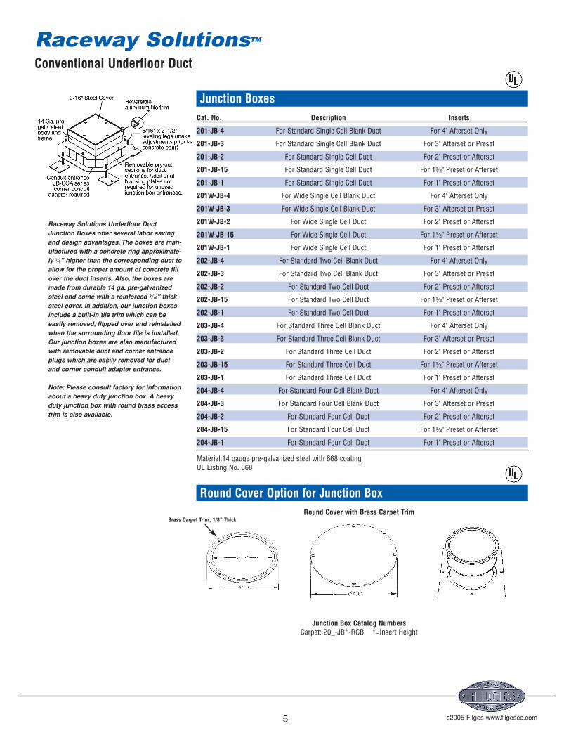
Junction BoxesCat. No. Description Inserts
201-JB-4 For Standard Single Cell Blank Duct For 4" Afterset Only
201-JB-3 For Standard Single Cell Blank Duct For 3" Afterset or Preset
201-JB-2 For Standard Single Cell Duct For 2" Preset or Afterset
201-JB-15 For Standard Single Cell Duct For 1½" Preset or Afterset
201-JB-1 For Standard Single Cell Duct For 1" Preset or Afterset
201W-JB-4 For Wide Single Cell Blank Duct For 4" Afterset Only
201W-JB-3 For Wide Single Cell Blank Duct For 3" Afterset or Preset
201W-JB-2 For Wide Single Cell Duct For 2" Preset or Afterset
201W-JB-15 For Wide Single Cell Duct For 1½" Preset or Afterset
201W-JB-1 For Wide Single Cell Duct For 1" Preset or Afterset
202-JB-4 For Standard Two Cell Blank Duct For 4" Afterset Only
202-JB-3 For Standard Two Cell Blank Duct For 3" Afterset or Preset
202-JB-2 For Standard Two Cell Duct For 2" Preset or Afterset
202-JB-15 For Standard Two Cell Duct For 1½" Preset or Afterset
202-JB-1 For Standard Two Cell Duct For 1" Preset or Afterset
203-JB-4 For Standard Three Cell Blank Duct For 4" Afterset Only
203-JB-3 For Standard Three Cell Blank Duct For 3" Afterset or Preset
203-JB-2 For Standard Three Cell Duct For 2" Preset or Afterset
203-JB-15 For Standard Three Cell Duct For 1½" Preset or Afterset
203-JB-1 For Standard Three Cell Duct For 1" Preset or Afterset
204-JB-4 For Standard Four Cell Blank Duct For 4" Afterset Only
204-JB-3 For Standard Four Cell Blank Duct For 3" Afterset or Preset
204-JB-2 For Standard Four Cell Duct For 2" Preset or Afterset
204-JB-15 For Standard Four Cell Duct For 1½" Preset or Afterset
204-JB-1 For Standard Four Cell Duct For 1" Preset or Afterset
Material:14 gauge pre-galvanized steel with 668 coatingUL Listing No. 668
Round Cover Option for Junction BoxRound Cover with Brass Carpet Trim
Junction Box Catalog NumbersCarpet: 20_-JB*-RCB *=Insert Height
Raceway Solutions Underfloor DuctJunction Boxes offer several labor savingand design advantages. The boxes are man-ufactured with a concrete ring approximate-ly ¼" higher than the corresponding duct toallow for the proper amount of concrete fillover the duct inserts. Also, the boxes aremade from durable 14 ga. pre-galvanizedsteel and come with a reinforced 3/16" thicksteel cover. In addition, our junction boxesinclude a built-in tile trim which can beeasily removed, flipped over and reinstalledwhen the surrounding floor tile is installed.Our junction boxes are also manufacturedwith removable duct and corner entranceplugs which are easily removed for ductand corner conduit adapter entrance.
Note: Please consult factory for informationabout a heavy duty junction box. A heavyduty junction box with round brass accesstrim is also available.
Conventional Underfloor Duct
Brass Carpet Trim, 1/8” Thick

Raceway SolutionsTM
c2005 Filges www.filgesco.com6
End Cap/SupportsCat.No. Description
201-ECS Standard Single Cell Duct
201W-ECS Wide Single Cell Duct
202-ECS Two Cell Duct
203-ECS Three and Four Cell Duct
Raceway Solutions End Cap/Supports provide a means of supporting and closing unused duct ends.Material: 14 gauge pre-galvanized steel with 668 coatingUL Listing No. 668
Conduit AdaptersCat.No. Description
201-UCA Standard Single Cell Duct
201W-UCA Wide Single Cell Duct
202-UCA Two Cell Duct
203-UCA Three Cell Duct
204-UCA Four Cell Duct
Raceway Solutions End Conduit Adapters are provided with a removable blank cover which is field punched for the required com-bination of conduits. Conduit adapters for multi-compartment duct are supplied with interior barriers to maintain separationbetween services.
Material: 14 gauge pre-galvanized steel with 668 coatingUL Listing No. 668
Junction Box Corner Conduit AdaptersCat.No. Description
JB-CCA-B With Removable Blank Cover
JB-CCA-1/2 With pre-punched ½" k.o.
JB-CCA-3/4 With pre-punched ¾" k.o.
JB-CCA-1 With pre-punched 1" k.o.
JB-CCA-1-1/2 With pre-punched 1½" k.o.
JB-CCA-2 With pre-punched 2" k.o.
Features a 16 gauge galvanized steel removable cover that may be field punched for required conduit. Material: 14 gauge pre-galvanized steel with 668 coatingUL Listing No. 668
Vertical RisersCat.No. Description
201-VEL Standard Single Cell Duct
201W-VEL Wide Single Cell Duct
202-VEL Two Cell Duct
203-VEL Three Cell Duct
204-VEL Four Cell Duct
Material: 14 gauge pre-galvanized steel with 668 coatingUL Listing No. 668
Conventional Underfloor Duct

Raceway SolutionsTM
c2005 Filges www.filgesco.com7
Horizontal Elbows – 90 °Cat.No. Description
201-HB90 Standard Single Cell Duct
201W-HB90 Wide Single Cell Duct
202-HB90 Two Cell Duct
203-HB90 Three Cell Duct
204-HB90 Four Cell Duct
Material: 14 gauge pre-galvanized steel with 668 coatingUL Listing No. 668
Duct Cabinet ConnectorsCat.No. Description
201-DCC Standard Single Cell Duct
201W-DCC Wide Single Cell Duct
202-DCC Two Cell Duct
203-DCC Three and Four Cell Duct
Material: 14 gauge pre-galvanized steel with 668 coatingUL Listing No. 668
Afterset Inserts – 2" IPS ThreadCat.No. Height
DAI-1 1"
DAI-2 2"
DAI-3 3"
DAI-4 4"
Material: Zinc die cast
Marker CapsCat.No. Description
DMC-Z Insert marker cap with zinc screw
DMC-B Insert marker cap with brass screw
Material: 14 gauge pre-galvanized steel with 668 coatingUL Listing No. 668
Reducing BushingsCat.No. Description
RB-162 2" to ¾"
RB-163 2" to 1"
Material: Steel, Zinc PlatedUL Listing No. E-1275
Conventional Underfloor Duct

Raceway SolutionsTM
c2005 Filges www.filgesco.com8
Service Fittings for PowerCat. Dimensions Wt.No. Description Finish W D H (lbs.)
PSF-10-DR Furnished with one 15 amp, Brushed 4⅜" 3" 2⅝" 1.6125 volt, 3-wire NEMA Aluminumduplex receptacle
PSF-10 Same as PSF-10-DR Brushed 4⅜" 3" 2⅝" 1.5above less duplex receptacle Aluminum
PSF-20-2DR Furnished with two back to back Brushed 5" 3⅜" 3" 1.3815 amp, 125 volt, 3 wire NEMA Aluminumduplex receptacles
PSF-20 Same as PSF-20-2DR less Brushed 5" 3⅜" 3" 1.25duplex receptacles Aluminum
PSF-21 Furnished with cover plate to Brushed 5" 3⅜" 3" 1.25accommodate one 30 or 50 amp, Aluminum240 volt, 3 wire receptacle andblank cover
PSF-20 Series Component Parts
PSF-20-BASE Standard above floor service fitting base only.
PSF-20-TELEDVP Device plate for PSF-20 with 1" dia. hole.
PSF-20-DUPDVP Device plate for PSF-20 for duplex.
PSF-20-BLDVP Blank device plate for PSF-20.
PSF-20-DVP139 Device plate for PSF-20 with 1⁄" dia. hole.
UL Listing No. 514A
Service Fittings for Communications and Data
Cat. Dimensions Wt.No. Description Finish W D H (lbs.)
CMSF-10 3⁄4 "x 1⅛" bushed opening for Brushed 4⅜" 3⅛" 2⅝" 1.5telephone or computer Aluminum
UL Listing No. 514A
PSF-10-DR
PSF-10 Series• Brushed aluminum finish.• Low profile design.• Furnished with 1" conduit nipple.
PSF-20-2DR
PSF-20 Series• Brushed aluminum finish.• Interchangeable face plates.• Furnished with 1" conduit nipple for
direct screw-threading into a floor boxplate with 1" cover opening.
CMSF-10• Brushed aluminum finish• Low profile design• Furnished with 1" conduit nipple
PSF-20-Base
Telephone Plate,1" HolePSF-20-
TELEDVP
BlankPlate
PSF-20-BLDVP
DuplexReceptacle
PlatePSF-20-DUPDVP
Single ReceptaclePlate, 1.39" Hole
PSF-20-DVP139
Single ReceptaclePlate, 1.60" Hole
PSF-20-DVP160
Service Head Fittings
Raceway Solutuions service fittings provide and data. A variety of service fittingabove-floor service for power, communications designs are available.
Conventional Underfloor Duct
Conventional Underfloor Duct Specifications
c2005 Filges www.filgesco.com9
Part 1 -GENERAL1.1 SUMMARY
Work under this section includesall labor and materials which arerequired for the completion of infloordistribution system, as shown ondrawings and as specified. TheConditions of the Contract apply tothis section as fully as if repeatedherein.1.1.1 Work includes, but is notnecessarily limited to the followingprincipal items.
a.Raceway Solutions metal underfloorraceway.
b.Related accessories, to includejunction boxes,supports, closures,and all other items necessary to theRaceway Solutions system.1.2 REFERENCES: The editions ofspecifications and standardsreferenced herein, published by thefollowing organizations, apply to thework only to the extent specified bythe reference.
a. Underwriters Laboratories,Inc.(UL Standard 884)
b. National Electric Code (NFPANo. 70)1.3 QUALITY ASSURANCE:1.3.1 Standards:
.1 The material, products andequipment specified in this sectionestablish a standard of quality ofrequired function, dimension,appearance and quality to be met byany proposed substitution.
.2 The manufacturer and installershall demonstrate a minimum of fiveyears experience with this type ofunderfloor duct system.1.4 SUBSTITUTIONS:1.4.1 No substitution will beconsidered unless written request forapproval has been submitted by thebidder and has been received by theArchitect at least ten (10) days prior tothe date for receipt of bids.1.4.2 Each such request shall includethe name of the materials orequipment for which it is to besubstituted and a completedescription of the proposed substitute
including drawings, cuts, mock-ups,performance and test data,compliance with codes and approvalsand any other information necessaryfor evaluation.1.5 SUBMITTALS:1.5.1 Manufacturer’s Data: Submitmanufacturer’s specifications andinstallation instructions for eachproduct specified. Includemanufacturer’s certification as may berequired to show compliance withthese specifications. Indicate bytransmittal form that a copy of eachinstruction has been distributed to theinstaller.1.5.2 Shop Drawings:
.1 Submit detailed drawingsshowing layout of all RacewaySolutions raceways, junction boxes,and accessories as necessary for theproper installation of the infloorsystem.
PART 2 -PRODUCTS2.1 RACEWAY SOLUTIONS RACEWAY2.1.1 Typical module as shown ondrawings consisting of 1, 2, 3 or 4compartment raceways.2.1.2 Materials: Raceway Solutionsduct shall be fabricated from 14 (2mm)gauge steel.2.1.3 Capacity: Raceway Solutions 201Series Raceway shown have outsidedimensions of 3½" x 1½".201W Series: 5⅞" x 1½"202 Series: 10" x 1½"203 Series: 15" x 1½"204 Series: 15" x 1½"2.1.4 Raceway Solutions Fabrication:
.1 The Raceway Solutions ductunits shall be manufactured in maxi-mum lengths of 10’ (3048 mm).
.2 Protective Coating: The RacewaySolutions duct shall be coated for cor-rosion resistance.2.1.5 Preset Inserts:
.1 Preset inserts shall be mounted 12"(304.8 mm) or 24" (609.6 mm) on center onthe Raceway Solutions duct raceway.
.2 The preset inserts shall be made ofzinc die cast, and shall be a minimumof 1" (25.4 mm) over top of the duct.
.3 The preset inserts will have aninside diameter of 2" (50.8) IPScapable of housing 2" (50.8 mm)conduit.
.4 The preset inserts shall have abeveled base which is expanded intothe duct to form a continuouspassageway.
.5 Each preset insert will have aremovable cap that is recessed toreceive concrete.2.1.6 Junction Boxes:
.1 The junction boxes shall haveopenings in all 4 corners for conduitadapters.
.2 The junction box shall have pre-pour adjustment (vertical and angular)via 4 leveling legs.
.3 The junction box shall besupplied with integral aluminum tiletrim.
.4 All duct and conduitconnections shall be completelygrounded via a grounding screw.
.5 Junction box shall containinclusive tile trim.2.2 ACTIVATIONS2.2.1 Supply activation assemblies asrequested.2.2.2 The manufacturer shall supplythe necessary pieces to transitionfrom the 2" (50.8 mm) I.P.S. preset tothe service fitting upon request.2.2.3 Activation assemblies shall beRaceway Solutions PSF-20 series, PSF-10series, CMSF-10 series HELP2.2.4 Activation assemblies shall bepedestal style (as specified).3.1 RACEWAY SOLUTIONS UNDERFLOORDUCT INSTALLATION3.1.1 Install distribution racewaysystem and accessories inaccordance with the manufacturer’srecommendation, installationinstructions, the final installationdrawings and as herein specified.Electrical module lines shall be laidout on the concrete base in eachbuilding bay and the raceway unitsshall be located in strict accordancewith the electrical drawings in order to
Raceway SolutionsTM

c2005 Filges www.filgesco.com10
maintain the electrical modulespacing.3.1.2 Place raceway system on thesupporting framework and adjust tofinal position with proper end bearingand alignment at the butt joints beforepermanent fastening. All joints shallbe secured with grounding screws.3.1.3 Permanently fasten the racewaysupports to the supporting frameworkwith screws and nails. Spacingbetween support shall not exceed 5’-0" (1524 mm).3.1.4 The raceway supports and theraceway distribution system shall beadjusted so the top of the presets are1/8 (3.2 mm) inch to 3/8 (9.5 mm) inchbelow the screed line.3.1.5 Marker screw caps shall beused in place of the standard insertcaps at the following locations: (a) ineach insert adjacent to a junction box;(b) in inserts on each side of apermanent wall, and (c) in the lastinsert in each run of duct.3.1.6 Do not use the installed racewaysystem for working platforms orwalkways.3.1.7 After placing of concrete fill andbefore wiring is installed, removedebris and other foreign materials.3.1.8 If moisture is present, removecover plates as necessary to allow aircirculation.3.2 FIELD QUALITY CONTROL:3.2.1 Field testing and inspection arespecified in Section 01410.3.2.2 Protection: Protect installation offloor system from damage. Do notallow equipment or heavy traffic overRaceway Solutions duct during con-struction period, without first installingramps over the duct. Ramps shall bedesigned so that imposed loads arenot transferred to Raceway Solutionsduct. Replace components of the sys-temwhich are damaged duringconstruction, at no cost to the Owner.3.2.3 The installed Raceway Solutionsraceway system shall be U.L. ListedUnder Standard 884 and shall comply with
Article 354 of the National ElectricCode.3.3 CONCRETE PLACEMENT:3.3.1 Concrete topping shall be asindicated on the drawings and asspecified under Section 03300.Concrete containing chlorides fromany source shall not be placed overinfloor units.3.3.2 Before concrete placement,make a final inspection of the entireRaceway Solutions system. Any gaps in the system shall be sealed to pre-vent mortar or concrete from entering.3.3.3 Reinforced concrete designshall be in accordance with AmericanConcrete Institute Specifications forStructural Concrete for Buildings(ACI301-72) and ACI Building CodeRequirements for ReinforcedConcrete (ACI1318-83). Concreteplacement shall follow proper andaccepted industry practice and be inaccordance with ACI RecommendedPractice for Measuring, Mixing,Transporting and Placing Concrete(ACI304-73), Concrete must bevibrated at all headers, junctionboxes, and raceway to insure that theconcrete completely fills underneaththe Raceway Solutions system.However, it is imperative that the con-crete not be over vibrated. Over vibra-tion causes segregation of materials inthe concrete mix which in turn leads toweakening of concrete strength.3.3.4 Shrinkage and temperaturereinforcement above the RacewaySolutions system shall be in accor-dance with ACI318-83. Care shall betaken during concrete placement and,in particular, during concrete vibration,to prevent rising of top reinforcementwithin the slab.3.3.5 Contractors placing theconcrete shall carefully hand finish aminimum of 24" (609.6 mm) adjacentto junction box access openings, sothat the top of finished concrete andjunction box access units are flush.
PART 4 -MANUFACTURER:4.1 Acceptable Brands:
a. Raceway Solutions by Dennis Filges Co. Inc..b.Other suppliers must submit 10
days prior for approval.
Conventional Underfloor Duct Specifications
Raceway SolutionsTM

c2005 Filges www.filgesco.com11
4.875 Sq.In.CompartmentConductor RHW/RHH TW THW THWN XHHW
14 75 140 93 201 14012 55 108 75 147 10810 45 80 59 92 80
5.4375 Sq.In.Compartment
Conductor RHW/RHH TW THW THWN XHHW
14 84 156 104 224 15612 62 120 84 164 12010 50 90 65 103 99
6.0 Sq.In.CompartmentConductor RHW/RHH TW THW THWN XHHW
14 92 173 115 247 17312 68 133 92 180 13310 55 99 72 114 99
7.5 Sq.In.CompartmentConductor RHW/RHH TW THW THWN XHHW14 115 216 144 309 21612 85 166 115 226 16610 69 123 90 142 123
8.8125 Sq.In.CompartmentConductor RHW/RHH TW THW THWN XHHW
14 136 254 169 363 25412 100 195 136 265 19510 81 145 106 167 145
10.125 Sq.In.Compartment
Conductor RHW/RHH TW THW THWN XHHW14 156 291 194 418 29112 115 224 156 305 22410 93 167 122 192 167
Number of allowable conductors at 40% fill.
Conventional Underfloor Duct Specifications
Raceway SolutionsTM
Estimating Raceway Solutions Conventional Underfloor DuctStep 1: Determine the total number of feet of duct you’ll need for your space.
Step 2: Calculate the number of pieces of duct necessary by dividing thetotal number of feet by 10. Always round up to the next wholenumber.
Example: Total length of duct = 226 feet226'/10' = 22.6 pcs.Total number of pieces required forthe job is 23.
Step 3: Determine number of junction boxes and accessories necessary forthe system.• Duct Couplers/Supports – one for every 5’ of duct.• Duct End Cap/Supports – close off unused duct ends.• Conduit Adapters – enters either the junction box or duct end.• Afterset inserts – used primarily with blank duct.• Service heads – PSF - series, CMSF-series or none.

Flush Activation Underfloor Duct
c2005 Filges www.filgesco.com12
Raceway Solutions Flush Activation Underfloor Duct provides an aesthetic wire manage-ment solution for delivering power and communications services. The new flush-styleinserts, which use standard floor box covers for power and data outlets, make it theideal underfloor duct solution for office environments, retail locations, casinos, andmedical facilities. Raceway Solutions Flush Activation Underfloor Duct sets the standard for fast, easy installation by incorporating a unique one-piece duct design along withintegral coupler/supports.
Raceway Solutions Flush Activation Underfloor Duct also sets the standard for application flexibility. The duct comes with activation inserts pre-assembled to the duct,or the inserts can be purchased separately for field installation only where you need them. Unique multi-gang inserts with removable voltage dividers provide the flexibility of installing multiple gangs of the same service at each insert location. In addition, theuse of standard floor box covers enables a wide variety of power and data outlets.
Features & Benefits:
• Available in 1-, 2-, and 3- compartment duct configurations
Unique one-piece duct reduces installation labor.Welded-in dividers create separate channels for power & communications services.
• Unique multi-gang inserts offer application flexibilityRemovable voltage dividers allow multiple gangs of the same service at each insertlocation.
Individual gangs can be activated as needed – keeps costs down.Afterset inserts are available for field installation – inserts only where you need themto minimize system cost.
• Aesthetic, flush-mounted activation trims are available for both carpet and tileapplications
Brass, aluminum and nonmetallic trims are available.Tile trims have after-pour adjustability to accommodate variations in tile thickness.
• Activation trims accept standard Raceway Solutions Floor Box CoversBrass, aluminum and nonmetallic covers are available.Complete cover offering accommodates a wide range of applications.
• Combination coupler/supports simplify installationSame part is used to join raceway sections together and to support/level the duct –reduces labor & material.
Raceway SolutionsTM

201F SeriesSingle Compartment
201WF SeriesWide Single Compartment
202F SeriesTwo Compartment
203F SeriesThree Compartment
c2005 Filges www.filgesco.com13
Duct SectionsCat.No. Duct Depth Duct Width Compartment Width Insert Height Insert Spacing
201-B 1½" 3¼" A =3¼" (no inserts) (no inserts)201F-3-24 1½" 3¼" A =3¼" 3" 24"201F-2-24 1½" 3¼" A =3¼" 2" 24"201F-15-24 1½" 3¼" A =3¼" 1½" 24"201F-3-12 1½" 3¼" A =3¼" 3" 12"201F-2-12 1½" 3¼" A =3¼" 2" 12"201F-15-12 1½" 3¼" A =3¼" 1½" 12"201W-B 1½" 5⅞" A =5⅞" (no inserts) (no inserts)201WF-3-24 1½" 5⅞" A =5⅞" 3" 24"201WF-2-24 1½" 5⅞" A =5⅞" 2" 24"201WF-15-24 1½" 5⅞" A =5⅞" 1½" 24"201WF-3-12 1½" 5⅞" A =5⅞" 3" 12"201WF-2-12 1½" 5⅞" A =5⅞" 2" 12"201WF-15-12 1½" 5⅞" A =5⅞" 1½" 12"202-B 1½" 10" A & B = 5" (no inserts) (no inserts)202F-3-24 1½" 10" A & B = 5" 3" 24"202F-2-24 1½" 10" A & B = 5" 2" 24"202F-15-24 1½" 10" A & B = 5" 1½" 24"202F-3-12 1½" 10" A & B = 5" 3" 12"202F-2-12 1½" 10" A & B = 5" 2" 12"202F-15-12 1½" 10" A & B = 5" 1½" 12"203F-B 1½" 15" A & C = 6"- B =3" (no inserts) (no inserts)203F-3-24 1½" 15" A & C = 6"- B =3" 3" 24"203F-2-24 1½" 15" A & C = 6"- B =3" 2" 24"203F-15-24 1½" 15" A & C = 6"- B =3" 1½" 24"203F-3-12 1½" 15" A & C = 6"- B =3" 3" 12"203F-2-12 1½" 15" A & C = 6"- B =3" 2" 12"203F-15-12 1½" 15" A & C = 6"- B =3" 1½" 12"
All duct sections 10’ long, 14 gauge pre-galvanized steel.
Junction BoxesCat. No. Description
201-JB-3 Junction box for 201 Series Duct with 3" high inserts201-JB-2 Junction box for 201 Series Duct with 2" high inserts201-JB-15 Junction box for 201 Series Duct with 1½" high inserts201W-JB-3 Junction box for 201W Series Duct with 3" high inserts201W-JB-2 Junction box for 201W Series Duct with 2" high inserts201W-JB-15 Junction box for 201W Series Duct with 1½" high inserts202-JB-3 Junction box for 202 Series Duct with 3" high inserts202-JB-2 Junction box for 202 Series Duct with 2" high inserts202-JB-15 Junction box for 202 Series Duct with 1½" high inserts203F-JB-3 Junction box for 203F Series Duct with 3" high inserts203F-JB-2 Junction box for 203F Series Duct with 2" high inserts203F-JB-15 Junction box for 203F Series Duct with 1½" high inserts
Flush Activation Underfloor Duct
Raceway SolutionsTM
Catalog Number System
20_F - 3 - 12
# of Cells Insert Height Insert Spacing1 = Single Cell B = Blank1W = Single Cell Wide 15 = 1½” Height 12 & 24 Standard2 = Two Cell 2 = 2” Height 6, 18, & 36 (optional)3 = Three Cell 3 = 3” Height

c2005 Filges www.filgesco.com14
Coupler/SupportCat. No. Description
201-DCS Duct Coupler/Support for 201 Series Duct201W-DCS Duct Coupler/Support for 201W Series Duct202-DCS Duct Coupler/Support for 202 Series Duct203-DCS Duct Coupler/Support for 203F Series Duct
Provides means for coupling duct sections together and for supporting the duct system. It isrecommended that a support/coupler be used every 5' of duct run.Material: 14 gauge pre-galvanized steel
End Cap/SupportCat. No. Description
201-ECS Duct End Cap/Support for 201 Series Duct201W-ECS Duct End Cap/Support for 201W Series Duct202-ECS Duct End Cap/Support for 202 Series Duct203-ECS Duct End Cap/Support for 203F Series Duct
Provides means for supporting and closing off unused duct ends.Material: 14 gauge pre-galvanized steel
Cabinet ConnectorCat. No. Description
201-DCC Duct Cabinet Connector for 201 Series Duct201W-DCC Duct Cabinet Connector for 201W Series Duct202-DCC Duct Cabinet Connector for 202 Series Duct203-DCC Duct Cabinet Connector for 203F Series Duct
Provides means for connecting duct to an electrical cabinet.Material: 14 gauge pre-galvanized steel
Conduit AdapterCat. No. Description
201-UCA Universal Conduit Adapter for 201 Series Duct201W-UCA Universal Conduit Adapter for 201W Series Duct202-UCA Universal Conduit Adapter for 202 Series Duct203F-UCA Universal Conduit Adapter for 203F Series Duct
Provides means for attaching conduit to the underfloor duct system at the junction box. Theconduit adapter is inserted into a main duct entrance. The blank cover can be field-punched forthe required combination of conduits.Material: 14 gauge pre-galvanized steel
Flush Activation Underfloor Duct
Raceway SolutionsTM
c2005 Filges www.filgesco.com15
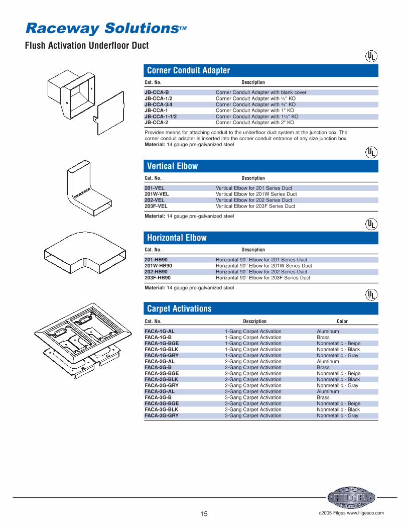
Corner Conduit AdapterCat. No. Description
JB-CCA-B Corner Conduit Adapter with blank coverJB-CCA-1/2 Corner Conduit Adapter with ½" KOJB-CCA-3/4 Corner Conduit Adapter with ¾" KOJB-CCA-1 Corner Conduit Adapter with 1" KOJB-CCA-1-1/2 Corner Conduit Adapter with 1½" KOJB-CCA-2 Corner Conduit Adapter with 2" KO
Provides means for attaching conduit to the underfloor duct system at the junction box. Thecorner conduit adapter is inserted into the corner conduit entrance of any size junction box.Material: 14 gauge pre-galvanized steel
Vertical ElbowCat. No. Description
201-VEL Vertical Elbow for 201 Series Duct201W-VEL Vertical Elbow for 201W Series Duct202-VEL Vertical Elbow for 202 Series Duct203F-VEL Vertical Elbow for 203F Series Duct
Material: 14 gauge pre-galvanized steel
Horizontal ElbowCat. No. Description
201-HB90 Horizontal 90° Elbow for 201 Series Duct201W-HB90 Horizontal 90° Elbow for 201W Series Duct202-HB90 Horizontal 90° Elbow for 202 Series Duct203F-HB90 Horizontal 90° Elbow for 203F Series Duct
Material: 14 gauge pre-galvanized steel
Carpet ActivationsCat. No. Description Color
FACA-1G-AL 1-Gang Carpet Activation AluminumFACA-1G-B 1-Gang Carpet Activation BrassFACA-1G-BGE 1-Gang Carpet Activation Nonmetallic - BeigeFACA-1G-BLK 1-Gang Carpet Activation Nonmetallic - BlackFACA-1G-GRY 1-Gang Carpet Activation Nonmetallic - GrayFACA-2G-AL 2-Gang Carpet Activation AluminumFACA-2G-B 2-Gang Carpet Activation BrassFACA-2G-BGE 2-Gang Carpet Activation Nonmetallic - BeigeFACA-2G-BLK 2-Gang Carpet Activation Nonmetallic - BlackFACA-2G-GRY 2-Gang Carpet Activation Nonmetallic - GrayFACA-3G-AL 3-Gang Carpet Activation AluminumFACA-3G-B 3-Gang Carpet Activation BrassFACA-3G-BGE 3-Gang Carpet Activation Nonmetallic - BeigeFACA-3G-BLK 3-Gang Carpet Activation Nonmetallic - BlackFACA-3G-GRY 3-Gang Carpet Activation Nonmetallic - Gray
Flush Activation Underfloor Duct
Raceway SolutionsTM

c2005 Filges www.filgesco.com16
Tile ActivationsCat. No. Description Color
FATA-AL Tile Activation AluminumFATA-B Tile Activation BrassFATA-BGE Tile Activation Nonmetallic - BeigeFATA-BLK Tile Activation Nonmetallic - BlackFATA-GRY Tile Activation Nonmetallic - Gray
Note: One Tile Activation is required for each gang of the insert.Provides means for height adjustment after the concrete pour to accommodatedifferent tile thickness.
Metallic CoversCat. No. Description Color
FA-MCP-1/2-B Cover Plate w/ ½" NPS Plug BrassFA-MCP-1/2-AL Cover Plate w/ ½" NPS Plug AluminumFA-MCP-3/4-B Cover Plate w/ ¾" NPS Plug BrassFA-MCP-3/4-AL Cover Plate w/ ¾" NPS Plug AluminumFA-MCP-1-B Cover Plate w/ 1" NPS Plug BrassFA-MCP-1-AL Cover Plate w/ 1" NPS Plug AluminumFA-MCP-1-1/4-B Cover Plate w/ 1¼" NPS Plug BrassFA-MCP-1-1/4-AL Cover Plate w/ 1¼" NPS Plug AluminumFA-MCP-2-B Cover Plate w/ 2" UN plug BrassFA-MCP-2-AL Cover Plate w/ 2" UN plug AluminumFA-MCP-1/2-2-B Cover Plate w/ 2" UN & ½" NPS plugs BrassFA-MCP-1/2-2-AL Cover Plate w/ 2" UN & ½" NPS plugs AluminumFA-MCP-3/4-2-B Cover Plate w/ 2" UN & ¾" NPS plug BrassFA-MCP-3/4-2-AL Cover Plate w/ 2" UN & ¾" NPS plug AluminumFA-MCP-2-5/8-B Cover Plate w/ 2⅝" UN plug BrassFA-MCP-2-5/8-AL Cover Plate w/ 2⅝" UN plug AluminumFA-MCP-DP-B Cover Plate w/ Two 1 7/16" Plugs for Duplex BrassFA-MCP-DP-AL Cover Plate w/ Two 1 7/16" Plugs for Duplex AluminumFA-MCP-FDP-B Cover Plate w/ Two Flip Lids for Duplex BrassFA-MCP-FDP-AL Cover Plate w/ Two Flip Lids for Duplex AluminumFA-MCP-GFCI-B Cover Plate w/ One Flip Lid for GFCI Brass
Nonmetallic CoversCat. No. Description Color
FAPCP-U-BGE Universal Cover Plate for Duplex &GFCI BeigeFAPCP-U-BLK Universal Cover Plate for Duplex &GFCI BlackFAPCP-U-GRY Universal Cover Plate for Duplex &GFCI GrayFAPCP-BP-BGE Blank Cover Plate BeigeFAPCP-BP-BLK Blank Cover Plate BlackFAPCP-BP-GRY Blank Cover Plate Gray
Flush Activation Underfloor Duct
Raceway SolutionsTM
c2005 Filges www.filgesco.com17
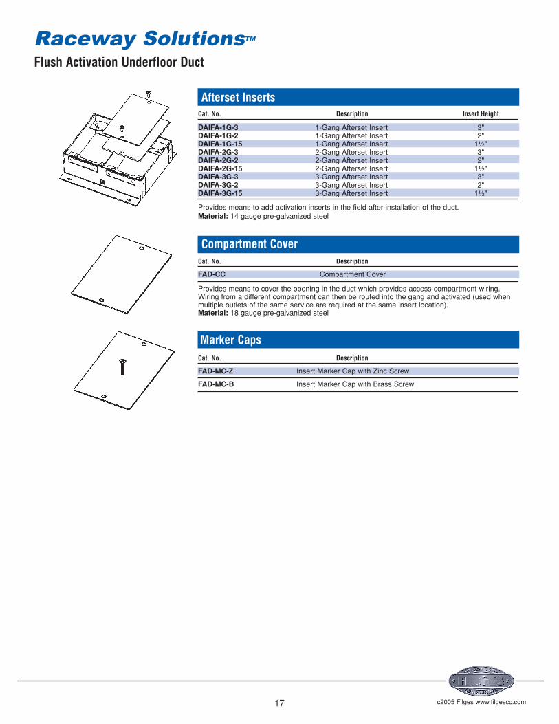
Afterset InsertsCat. No. Description Insert Height
DAIFA-1G-3 1-Gang Afterset Insert 3"DAIFA-1G-2 1-Gang Afterset Insert 2"DAIFA-1G-15 1-Gang Afterset Insert 1½"DAIFA-2G-3 2-Gang Afterset Insert 3"DAIFA-2G-2 2-Gang Afterset Insert 2"DAIFA-2G-15 2-Gang Afterset Insert 1½"DAIFA-3G-3 3-Gang Afterset Insert 3"DAIFA-3G-2 3-Gang Afterset Insert 2"DAIFA-3G-15 3-Gang Afterset Insert 1½"
Provides means to add activation inserts in the field after installation of the duct.Material: 14 gauge pre-galvanized steel
Compartment CoverCat. No. Description
FAD-CC Compartment Cover
Provides means to cover the opening in the duct which provides access compartment wiring.Wiring from a different compartment can then be routed into the gang and activated (used whenmultiple outlets of the same service are required at the same insert location).Material: 18 gauge pre-galvanized steel
Marker CapsCat. No. Description
FAD-MC-Z Insert Marker Cap with Zinc Screw
FAD-MC-B Insert Marker Cap with Brass Screw
Flush Activation Underfloor Duct
Raceway SolutionsTM
c2005 Filges www.filgesco.com18
COAXCABLES
LANCABLES
FIBER OPTICCABLES
62.5 /125 um
SIGNALCABLES
POWER(THHN)
201 SeriesSingle Compartment
201W SeriesWide Single Compartment
202 SeriesTwo Compartment
203F SeriesThree Compartment
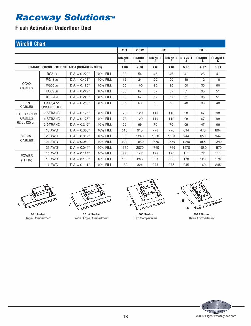
Wirefill Chart201 201W 202 203F
CHANNEL CHANNEL CHANNEL CHANNEL CHANNEL CHANNEL CHANNELA A A B A B C
CHANNEL CROSS SECTIONAL AREA (SQUARE INCHES): 4.38 7.78 6.60 6.60 5.90 4.07 5.90
RG6 /u DIA. = 0.270" 40% FILL 30 54 46 46 41 28 41
RG11 /u DIA. = 0.405" 40% FILL 13 24 20 20 18 12 18
RG58 /u DIA. = 0.193" 40% FILL 60 106 90 90 80 55 80
RG59 /u DIA. = 0.242" 40% FILL 38 67 57 57 51 35 51
RG62A /u DIA. = 0.242" 40% FILL 38 67 57 57 51 35 51
CAT5,4 pr. DIA. = 0.250" 40% FILL 35 63 53 53 48 33 48UNSHIELDED
2 STRAND DIA. = 0.175" 40% FILL 73 129 110 110 98 67 98
4 STRAND DIA. = 0.175" 40% FILL 73 129 110 110 98 67 98
6 STRAND DIA. = 0.210" 40% FILL 50 89 76 76 68 47 68
18 AWG DIA. = 0.066" 40% FILL 515 915 776 776 694 478 694
20 AWG DIA. = 0.057" 40% FILL 700 1240 1050 1050 944 650 944
22 AWG DIA. = 0.050" 40% FILL 922 1630 1380 1380 1240 856 1240
24 AWG DIA. = 0.044" 40% FILL 1160 2070 1760 1760 1570 1080 1570
10 AWG DIA. = 0.164" 40% FILL 83 147 125 125 111 77 111
12 AWG DIA. = 0.130" 40% FILL 132 235 200 200 178 123 178
14 AWG DIA. = 0.111" 40% FILL 182 324 275 275 245 169 245
Flush Activation Underfloor Duct
Raceway SolutionsTM

Casino Underfloor Duct
c2005 Filges www.filgesco.com19
Features & Benefits
• Heavy Duty cast aluminum junction box meets the high load requirements of acasino environment (50,000 pound uniform load rating).
• Two-compartment duct provides separation of power and voice/data.• Junction box provides individual covers for access to power and voice/data
compartments.• Attractive brass carpet trims are available for the junction box covers.• One-piece duct configuration simplifies assembly and leveling for reduced
installation costs.
• System includes a complete line of accessories and fittings for design flexibility.• System meets the requirements of UL 884.
Raceway SolutionsTM
c2005 Filges www.filgesco.com20
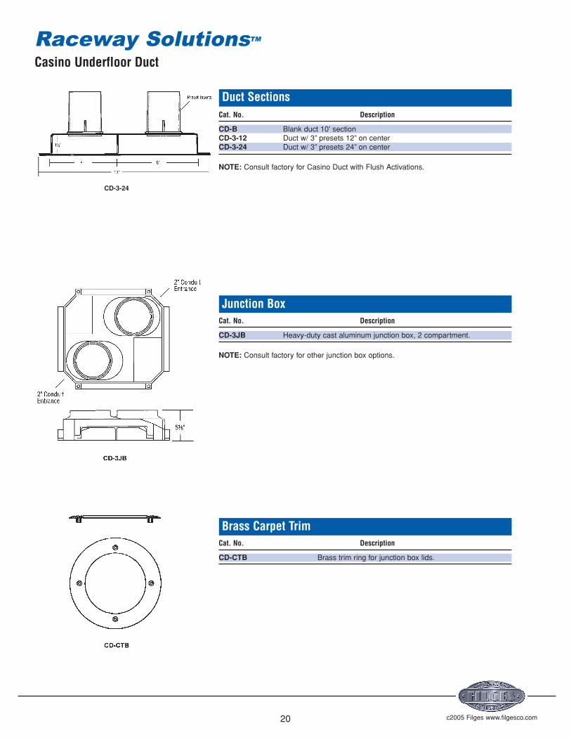
Duct SectionsCat. No. Description
CD-B Blank duct 10' sectionCD-3-12 Duct w/ 3” presets 12” on centerCD-3-24 Duct w/ 3” presets 24” on center
NOTE: Consult factory for Casino Duct with Flush Activations.
Junction BoxCat. No. Description
CD-3JB Heavy-duty cast aluminum junction box, 2 compartment.
NOTE: Consult factory for other junction box options.
Brass Carpet TrimCat. No. Description
CD-CTB Brass trim ring for junction box lids.
Casino Underfloor Duct
Raceway SolutionsTM
CD-3-24

c2005 Filges www.filgesco.com21
Coupler/SupportsCat. No. Description
CD-CS For Casino Duct
Material: 14 gauge pre-galvanized steel with 668 coatingUL Listing No. 668
Raceway Solutions duct coupler/supports provide a means of not only coupling duct sections together but alsosupporting the duct sections. It is recommended that a support/coupler be used every 5'of duct run.
End Cap/SupportCat. No. Description
CD-ES For Casino Duct
Raceway Solutions End Cap/Supports provide a means of supporting and closing unused duct ends.Material: 14 gauge pre-galvanized steel with 668 coatingUL Listing No. 668
Conduit AdapterCat. No. Description
CD-UCA For Casino Duct
Raceway Solutions End Conduit Adapters are provided with a removable blank cover which is fieldpunched for the required combination of conduits. Conduit adapters for multi-compartment ductare supplied with interior barriers to maintain separation between services.Material: 14 gauge pre-galvanized steel with 668 coatingUL Listing No. 668
Verticle RiserCat. No. Description
CD-VEL For Casino Duct
Material: 14 gauge pre-galvanized steel with 668 coatingUL Listing No. 668
Casino Underfloor Duct
Raceway SolutionsTM

c2005 Filges www.filgesco.com22
Horizontal Elbow – 90°Cat. No. Description
CD-HB90 For Casino Duct
Material: 14 gauge pre-galvanized steel with 668 coatingUL Listing No. 668
Horizontal Elbow – 45°Cat. No. Description
CD-HB45L 45° Elbow LeftCD-HB45R 45° Elbow Right
Material: 14 gauge pre-galvanized steel with 668 coatingUL Listing No. 668
Duct Cabinet ConnectorCat. No. Description
CD-CC For Casino Duct
Material: 14 gauge pre-galvanized steel with 668 coatingUL Listing No. 668
Afterset Insert – 2" IPS ThreadCat. No. Description
DAI-3 3"
Marker CapsCat. No. Description
DMC-Z Insert marker cap with zinc screwDMC-B Insert marker cap with brass screw
Material: 14 gauge pre-galvanized steel with 668 coatingUL Listing No. 668
Reducing BushingsCat. No. Description
RB-162 2" to ¾"RB-163 2" to 1"
Material: Steel, Zinc PlatedUL Listing No. E-1275
Casino Underfloor Duct
Raceway SolutionsTM

Service Head Fittings
Raceway Solutions service fittings provide and data. A variety of service fittingabove-floor service for power, communications designs are available.
Service Fittings for PowerCat. Dimensions Wt.No. Description Finish W D H (lbs.)
PSF-10-DR Furnished with one 15 amp, Brushed 4⅜" 3" 2⅝" 1.6125 volt, 3-wire NEMA Aluminumduplex receptacle
PSF-10 Same as PSF-10-DR Brushed 4⅜" 3" 2⅝" 1.5above less duplex receptacle Aluminum
PSF-20-2DR Furnished with two back to back Brushed 5" 3⅜" 3" 1.3815 amp,125 volt, 3 wire NEMA Aluminumduplex receptacles
PSF-20 Same as PSF-20-2DR less Brushed 5" 3⅜" 3" 1.25duplex receptacles Aluminum
PSF-21 Furnished with cover plate to Brushed 5" 3⅜" 3" 1.25accommodate one 30 or 50 amp, Aluminum240 volt, 3 wire receptacle andblank cover
SFH-20 Series Component Parts
PSF-20-BASE Standard above floor service fitting base only.
PSF-20-TELEDVP Device plate for PSF-20 with 1" dia. hole.
PSF-20-DUPDVP Device plate for PSF-20 for duplex.
PSF-20-BLDVP Blank device plate for PSF-20.
PSF-20-DVP139 Device plate for PSF-20 with 1⁄" dia. hole.
UL Listing No.514A
Service Fittings for Communications and Data
Cat. Dimensions Wt.No. Description Finish W D H (lbs.)
CMSF-10 ¾"x 1⅛" bushed opening for Brushed 4⅜" 3⅛" 2⅝" 1.5telephone or computer Aluminum
UL Listing No.514A
c2005 Filges www.filgesco.com23
PSF-10-DR
PSF-10 Series• Brushed aluminum finish.• Low profile design.• Furnished with 1" conduit nipple.
PSF-20-DRPSF-20 Series• Brushed aluminum finish.• Interchangeable face plates.• Furnished with 1" conduit nipple for
direct screw-threading into a floor boxplate with 1" cover opening.
CMSF-10• Brushed aluminum finish.• Low profile design.• Furnished with 1" conduit nipple.
PSF-20-Base
Telephone Plate,1" HolePSF-20-
TELEDVP
BlankPlate
PSF-20-BLDVP
DuplexReceptacle
PlatePSF-20-DUPDVP
Single ReceptaclePlate, 1.39" Hole
PSF-20-DVP139
Single ReceptaclePlate, 1.60" Hole
PSF-20-DVP160
Casino Underfloor Duct
Raceway SolutionsTM
c2005 Filges www.filgesco.com24
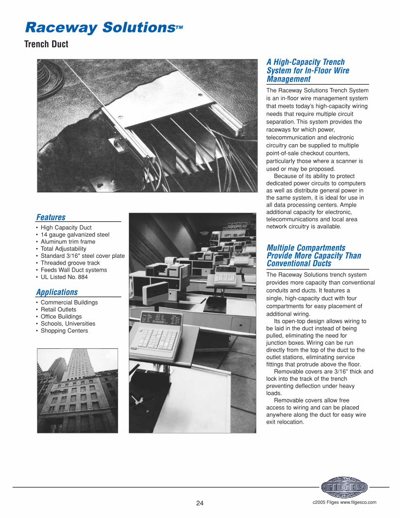
A High-Capacity TrenchSystem for In-Floor WireManagementThe Raceway Solutions Trench System is an in-floor wire management system that meets today’s high-capacity wiringneeds that require multiple circuitseparation. This system provides theraceways for which power,telecommunication and electroniccircuitry can be supplied to multiplepoint-of-sale checkout counters,particularly those where a scanner isused or may be proposed.
Because of its ability to protectdedicated power circuits to computersas well as distribute general power inthe same system, it is ideal for use inall data processing centers. Ampleadditional capacity for electronic,telecommunications and local areanetwork circuitry is available.
Multiple CompartmentsProvide More Capacity ThanConventional DuctsThe Raceway Solutions trench system provides more capacity than conventionalconduits and ducts. It features asingle, high-capacity duct with fourcompartments for easy placement ofadditional wiring.
Its open-top design allows wiring tobe laid in the duct instead of beingpulled, eliminating the need forjunction boxes. Wiring can be rundirectly from the top of the duct to theoutlet stations, eliminating servicefittings that protrude above the floor.
Removable covers are 3/16" thick andlock into the track of the trenchpreventing deflection under heavyloads.
Removable covers allow freeaccess to wiring and can be placedanywhere along the duct for easy wireexit relocation.
Features• High Capacity Duct• 14 gauge galvanized steel• Aluminum trim frame• Total Adjustability• Standard 3/16" steel cover plate• Threaded groove track• Feeds Wall Duct systems• UL Listed No. 884
Applications• Commercial Buildings• Retail Outlets• Office Buildings• Schools, Universities• Shopping Centers
Trench Duct
Raceway SolutionsTM

c2005 Filges www.filgesco.com25
Duct FrameDuct frame includes fixed metalpartitions that create multiplecompartments in the duct. This featurepermits a single duct to distributepower, electronics andcommunications. Duct with fewerpartitions is available to meet yourspecifications and can be located instrategic places to meet specialdistribution requirements.
The duct frame is available in avariety of sizes. The frame is of 14gauge galvanized steel and issupplied in standard 6' lengths. It canbe cut to length which increases fieldflexibility and eliminates the need forordering specialty fabricated material.
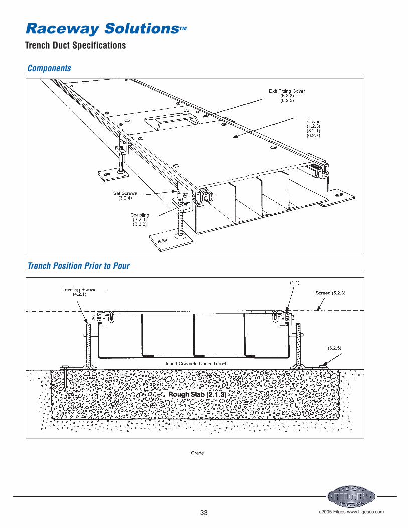
TrackThe track of the structural assemblyintegrates the base aluminum profilewith the tile trim, extruded rubber strip,and the duct support assembly. Thetrack also provides the screed line forthe concrete.• The aluminum profile accepts and
holds the duct frame, rubbercushion, and cover plate screws inaddition to supporting the coverplate; it also acts as a runner for theleveling screw clips.
• The aluminum tile trim provides afinished edge for the tile, assists incutting, and can be reversed whenthe trim is not required; can bereversed when carpet is used
• The extruded rubber gasket acts asa cushion, sound dampener andmoisture barrier between the coverplate and the duct; meets U.L.moptight requirements
Duct Support AssemblyThe unique duct support assemblyprovides one time leveling capabilityand acts as a splice for duct sections.The assembly consists of the levelingscrew clip, mounting plate, andleveling screws, and is independent ofthe final support of the duct.
Leveling screw allows for 1" adjustment.
• The leveling screw clip integrateswith the track and provides fulladjustment along the length of theduct; it also acts as the splice forduct sections
• The heavy gauge mounting platefastens duct to metal deck,roughslab,or wood/metal forms prior topouring concrete; it adjusts to meetmost floor and installationrequirements.
• The leveling screws provide verticaladjustment of the duct prior toconcrete pour; this allows the duct tobe leveled to the screed line so onlyone pour is required
CoverThe cover plates for the RacewaySolutions Trench Duct are horizontallyadjustable to any point along the duct.The 3/16" thick cover plates come instandard 24" lengths — three areprovided per 6' duct section. A 1/4"thick cover plate is also available as acustomer option.
A special threaded groove on thetrack accepts the cover plate screwsat any point along the duct, providingthe cover unlimited adjustment. Thisspecial design relieves the installerfrom matching the duct frame sectionswith the covers, eliminating fieldcutting in most instances. This cansubstantially reduce installation andmaintenance costs.
The cable exit may be installed onan exit fitting cover allowing cable tobe easily pulled out and activated.The cable exit is reversible to provideaccessibility from either direction. Thestandard cover plates may beremoved and exit fitting coversinstalled for the cable exit.
Trench Duct
Raceway SolutionsTM
Partition
LevelingScrew Clip
LevelingScrew
MountingPlate
CarpetTrim
AluminumProfile
Rubber Strip
ThreadedGroove
TileTrim

c2005 Filges www.filgesco.com26
Raceway Solutions Trench Duct is manufac-tured in 6 foot lengths complete with three lev-eling feet on each side (OK/F-2-1/2), threecover plates 24" long (OKC) and three coverjoint protectors (OK/DSD). The leveling feet(screw clips) permit 1" of vertical adjustmentand act as section couplers. Additional verticaladjustment is available on order by increasingthe length of the screw in the OK/F.NOTE: All vertical adjustment should be madebefore the concrete is poured.
Manufactured with a single cover and matchingcompartments to form a 90° Horizontal L.
Duct SectionsOutside
Cover Dimensions Compartment Area Cell WidthCat. Width (in.) (sq.in.) (in.)No. (c) H W A B C D A B C D
Four CompartmentOKA/B12-4C 12 2½ 12⅞ 6.6 6.6 6.6 6.6 3.15 3.15 3.15 3.15
Three CompartmentOKA/B9-3C 9 2½ 9⅞ 6.7 6.7 6.7 — 3.2 3.2 3.2 —OKA/B12-3C 12 2½ 12⅞ 8.8 8.8 8.8 — 4.2 4.2 4.2 —OKA/C12-3C 12 3 12⅞ 10.9 10.9 10.9 — 4.2 4.2 4.2 —
UL Listing No. 884
Catalog Number System
Horizontal L FittingCat. Associated Outside Cover No.ofNo. Trench Dimension Compartments
OKL/B9-3C OKA/B9-3C 12" x 12" 3
OKL/B12-4C OKA/B12-4C 15" x 15" 4
OKL/C12-3C OKA/C12-3C 15" x 15" 3
OKL/B12-3C OKA/B12-3C 15" x 15" 3
Note: Table only an example of available sizes. Please refer to above for catalog number system.
Trench Duct
Raceway SolutionsTM
Note: *Other depths and widths are available. Please consult factoryfor details. Also available in Aluminum.
OKA / B 12 4C - AL 1/4
¼“ Thick Cover Plate (optional)
Trench ProductOKA–TrenchOKB–Pull BoxOKC–Exit CoverOKE–End CapOKL–Horizontal LOKR–Vertical RiserOKT–”T” Junction BoxOKX–”X” Junction Box
Depth½” IncrementsA = 2”B = 2½”C = 3”D = 3½”E = 4”
J = 6”
N = 8”
*Other Depths Available
Number of Compartments1C = 1 Compartment2C = 2 Compartment3C = 3 Compartment4C = 4 Compartment
Aluminum(optional)
Width9, 12, 18, & 24
Standard(Other Widths Available)

c2005 Filges www.filgesco.com27
Single Level “T ” Junction FittingCat. Cover AssociatedNo. Dimensions Trench
OKT/B9-3C 15" x 12" OKA/B9-3C
OKT/B12-4C 18" x 15" OKA/B12-4C
OKT/B12-3C 18" x 15" OKA/B12-3C
OKT/C12-3C 18" x 15" OKA/C12-3C
Note: Table only an example of available sizes. Please refer to page 26 for catalog number system.
Single Level “X ” Junction FittingCat. Cover AssociatedNo. Dimensions Trench
OKX/B9-3C 15" x 15" OKA/B9-3C
OKX/B12-4C 18" x 18" OKA/B12-4C
OKX/B12-3C 18" x 18" OKA/B12-3C
OKX/C12-3C 18" x 18" OKA/C12-3C
End CapCat. MaximumNo. Width Conduit Depth
OKE/B9 10" 1¼" 2⁄"
OKE/B12 13" 1¼" 2⁄"
OKE/C12 13" 2" 3⁄"
Manufactured with internal partitionsand crossovers to isolate power andcommunication.
Manufactured with internal partitionsand crossovers to isolate power andcommunication.
Fits over end of trench run to close trench andprevent foreign material from entering. Endcap may be drilled to accept conduit.
Trench Duct
Raceway SolutionsTM

c2005 Filges www.filgesco.com28
Designed to provide exit and feed for RacewaySolutions Trench Duct trench. Conduit openingsare provided for power and communication exitor feed using conventional fittings or servicefittings. Cable exit cap (OKSK) is for communi-cation cable only. Exit fittings cover may bespaced anywhere along the length ofthe trench. All exit fitting covers are 6" long.
Fits opening on Exit Cover. Provides outlet forcommunication cable. Debris barrier included.Cable Exit Cap constructed from die castaluminum. For use with Type A exit covers only.
Trench to Wallduct AdapterCat. No. A
OWV/D12 11⁄"OWV/D18 17⁄"
Screws included.
Material: 14 gauge pre-galvanized steel.UL Listing No. E116245
Exit CoversCat. Conduit TrenchNo. Hole Size Width
OKC/9-3/4A 3⁄4 " 9"
OKC/12-3/4A 3⁄4 " 12"
OKC/9-3/4C 3⁄4 " 9"
OKC/12-3/4C 3⁄4 " 12"
Note: Table only an example of available sizes. Please refer to page 26 for catalog number system.
Cable Exit CapCat. No. Description
OKSK Cable Exit Cap
Trench Duct
Raceway SolutionsTM

c2005 Filges www.filgesco.com29
Manufactured to mount on trench in place ofcover.Partitioned to separate cells andflanged to attach to pull box. Removable frontcover and top cover. Standard height abovefinish floor —12 inches. Standard depth —3½"inches.
Manufactured to attach to trench sectionreplacing end cap. Divided into compartmentas shown.Additional depth permits attachmentof larger conduit. Will accept up to 4" conduit.Box is field punched.
Accessories to join trench sections for fieldfabrication of horizontal and verticalassemblies.
Vertical Riser FittingCat. Associated No.ofNo. Trench Compartments D W H
OKR/D9-3C OKA/B9-3C 3 3½" 9" 12"
OKR/D12-4C OKA/B12-4C 4 3½" 12" 12"
OKR/D12-3C OKA/B12-3C 3 3½" 12" 12"OKA/C12-3C
Note: Table only an example of available sizes. Please refer to page 26 for catalog number system.
Pull BoxCat. Associated DimensionsNo. Trench A B C
OKB/B9-3C OKA/B9-3C 6" 12" 9"
OKB/B12-4C OKA/B12-4C 6" 12" 12"
OKB/B12-3C OKA/B12-3C 6" 12" 12"
OKB/C12-3C OKA/C12-3C 6" 12" 12"
UL Listing No. 884
Fastening AnglesCat. No. Description
OK/VWI Horizontal Angle
OK/VVW Vertical Angle
Trench Duct
Raceway SolutionsTM
Trench Duct Specifications
c2005 Filges www.filgesco.com30
Specifications
Raceway Solution Trench Duct has beendesigned to offer the most completein-floor wire management system forcomputer terminals. The particular usefor retail store checkout countersusing scanners has been selected forthis catalog. Its potential capacity,unlimited point-of-delivery, and wirecompartmentalization provide flexibilityfor current requirements as well asfuture needs.
Raceway Solution Trench Duct maybe specified for stores that are beingretrofitted for the use of scanners aswell as new stores.
The specifier should consider thefollowing:
1. The two outer compartments forthe 12” size (2½" deep) have 6.6 in2
wiring capacity. (This provides greatercapacity than 2½" conduit). Two powercompartments are offered:
• One for computer dedicated circuits
• One for general purpose power
2. The outer compartments shouldbe chosen for the power since runs ofconduit can be tapped off the sides ofthe duct (¾" and 1") to speciallyplaced floor boxes or stubbed out ofthe concrete to provide power atlocations to the left or right of thetrench.
3. The inside compartments of thefour compartment 12" wide duct(OKA/B12-4C) each have 6.6 in2
wiring capacity in a cross-sectionalarea that is 3.0" x 2¼" on sides. Thelargest electronic connector can passthrough this area and exit with ease.One of these can be designated for
computer cables and the other forintercommunication or telephone.Depending on the sensitivity of thesystem, these two compartments maybe used interchangeably.
4. Covers may be adjusted to anylocation as well as the exit fittingcovers. Therefore, predetermination ofexit locations is not required andfuture access to the wiring at anylocation is available.
5. To feed the computer location orcheckout counter, service fittings withreceptacles may be used or the exitfitting cover hard wired to the point ofdelivery. For example, flexible metallicconduit or liquidtight conduit may beused between the exit fitting coverand a utility box with a receptacledirectly under the counter.
6. Cable exit caps may be used forcomputer, telephone, or intercom-munication cables. In certain cases,armored or other approved cable maybe permitted with the cable exit cap.
Raceway SolutionsTM
c2005 Filges www.filgesco.com31
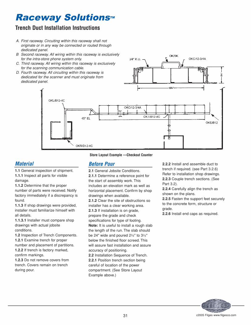
A. First raceway. Circuiting within this raceway shall notoriginate or in any way be connected or routed throughdedicated panel.
B Second raceway. All wiring within this raceway is exclusivelyfor the intra-store phone system only.
C. Third raceway. All wiring within this raceway is exclusivelyfor the scanning communication cable.
D. Fourth raceway. All circuiting within this raceway isdedicated for the scanner and must originate fromdedicated panel.
Material1.1 General inspection of shipment.1.1.1 Inspect all parts for visibledamage.1.1.2 Determine that the propernumber of parts were received. Notifyfactory immediately if a discrepancy isfound.1.1.3 If shop drawings were provided,installer must familiarize himself withall details.1.1.3.1 Installer must compare shopdrawings with actual jobsiteconditions.1.2 Inspection of Trench Components.1.2.1 Examine trench for propernumber and placement of partitions.1.2.2 If trench is factory marked,confirm markings.1.2.3 Do not remove covers fromtrench. Covers remain on trenchduring pour.
2.2.2 Install and assemble duct totrench if required. (see Part 3.2.6)Refer to installation shop drawings.2.2.3 Couple trench sections. (SeePart 3.2).2.2.4 Carefully align the trench asshown on the plans.2.2.5 Fasten the support feet securelyto the concrete form, structure orgrade.2.2.6 Install end caps as required.
Before Pour2.1 General Jobsite Conditions.2.1.1 Determine a reference point forthe start of assembly work. Thisincludes an elevation mark as well ashorizontal placement. Confirm by shopdrawings when available.2.1.2 Clear the site of obstructions soinstaller has a clear working area.2.1.3 If installation is on grade,prepare the grade and checkspecifications for type of footing.Note: It is useful to install a rough slabthe length of the run. The slab shouldbe 24" wide and poured 2½" to 3½"below the finished floor screed. Thiswill assure fast installation and assureaccuracy of positioning.2.2 Installation Sequence of Trench.2.2.1 Position trench section beingcareful of location of the powercompartment. (See Store LayoutExample above.)
Store Layout Example —Checkout Counter
Trench Duct Installation Instructions
Raceway SolutionsTM

c2005 Filges www.filgesco.com32
c. Partitions must match.d. Use OK/VWI to join pieces.3.2.9.4 A vertical Ell may be fieldfabricated using a section of trenchcut to desired height and OK/VVWfastening angles used to join sections.
Part 4 —Securing,Elevating and LevelingSystem Prior to Pour4.1 General. The top of the systemmust be at screed level. Specificallythis includes the trench covers.4.1.1 When elevating and levelingsystem use laser level, electroniclevel, transit, conventional level, or anyapproved system.4.2 Leveling Trench.4.2.1 Turn leveling screws of thetrench support assembly to bring thecover of the trench to screed.4.2.2 Level the trench in one directionto prevent distortion of system.
Part 5 —During and After Pour5.1 General Considerations5.1.1 Check installation for security,location and elevation.CAUTION: The covers of the systemserve as the screed line. They mustbe protected from accidentalmovement before and during pour.Correcting components for elevationafter concrete has set requiresextensive labor.5.1.2 If concrete mix is especially thin(fluid), gaps and openings in thesystem should be sealed with ducttape or other approved method.5.1.3 For aggregate greater than ¼inch, concrete flow aroundcomponents must be assured.5.2 Trench Components.5.2.1 Covers of trench serve as guidefor pouring concrete the level of thefinished floor.5.2.2 Concrete must be inserted undertrench by shovel or trowel.5.2.3 Hand screed to top of trench.5.2.4 The concrete must adhere tightlyto the trench edges.
Part 3 —Assembly of Components3.1 General Assembly Requirements3.1.1 The power compartment oftrench must match and be as shownon the plans.3.1.2 Continuity of ground must beassured in all metal parts.3.2 Trench Components.3.2.1 Do not remove covers beforepour.3.2.2 Trench sections are coupledusing coupling clip furnished on thealuminum profile at the end of thetrench. Clip may be part of thesupport assembly.3.2.3 Check match of internal partitionbefore completing couple.3.2.4 Set screws on trench couplingclip must be tightened to assurecontinuity of ground.3.2.5 If rough slab is not available(see 2.1.3 Note) special care must betaken to assure support of mountingfeet and protect against movementduring pour.3.2.6 Junction fittings to adapt trenchto underfloor raceway do not requirerough slab (see 2.1.3 Note) but mustbe secure.3.2.7 Underfloor raceway requiresconcrete around supports (couplers)and under raceway.3.2.8 Tape underfloor raceway ifingress of concrete could occur.3.2.9 Field modification of trench.3.2.9.1 Where necessary trench canbe cut on the jobsite. For this purpose,bandsaws, hacksaws, or cuttingwheels can be used.3.2.9.2 When field cutting, do notremove cover to assure a properfinished joint.3.2.9.3 Horizontal Ell ’s or offsets maybe field fabricated by cutting equalangles from each of the pieces to bejoined.a. 45° cuts from axis of trench join tomake a 90° horizontal offset.b. 22½° cuts join to make a 45°horizontal offset.
5.2.5 The covers of the trench must beexposed when the concrete floor isfinished.5.2.6 Remove sufficient covers toallow ventilation after concrete is set.
Part 6 —Activation6.1 Activation Sequence.6.1.1 Correct any variation in concretepour along edges of trench.6.1.2 Remove covers from trench, andinspect installation.6.2 Activating Trench.6.2.1 Upon removing covers 6.1.2, laythe covers beside the trench in theirrelative position.6.2.2 Where exit fitting covers or othertrench exit fittings are required, laythem beside the trench in their relativeposition.6.2.3 If floor finish is not to beinterrupted by tile trim to establishcontinuity of floor cover, tile trim is toremain in shipping position. Do notelevate.6.2.4 Lay the required wiring in thetrench.6.2.5 Mount the exit fitting covers orother trench exit fittings on trench atproper location.6.2.6 Install cover joint protectors.OK/DSD.6.2.7 Install standard covers. Coversmay be adjusted or cut if required tocomplete enclosure.6.2.8 Remove cover adjacent to exitfittings to complete wiring.6.2.9 Lay floor covering. Take care toassure level floor over trench. Usefloor patch if necessary.6.2.9.1 If tile trim is used, adhesionbetween outer tile and tile trim mustbe assured and tile on coversaccurately positioned.
Trench Duct Installation Instructions
Raceway SolutionsTM
c2005 Filges www.filgesco.com33
Components
Trench Position Prior to Pour
Trench Duct Specifications
Raceway SolutionsTM

c2005 Filges www.filgesco.com34
Dimensions – Trench DuctA B C D Total
OKA/B12-4C 6.6 6.6 6.6 6.6 26.4OKA/B12-3C 8.8 8.8 8.8 — 26.4OKA/B9-3C 6.7 6.7 6.7 — 20.1
3.4 Sq.In.CompartmentConductor RHW/RHH TW THW THWN XHHW
14 41 100 66 156 10312 35 79 53 116 8110 29 61 43 73 628 16 28 22 36 296 10 16 16 26 21
5.0 Sq.In.Compartment
Conductor RHW/RHH TW THW THWN XHHW
14 61 148 97 229 15212 52 116 79 170 11910 43 90 64 108 928 23 42 33 53 436 16 24 24 38 32
5.4 Sq.In.CompartmentConductor RHW/RHH TW THW THWN XHHW
14 66 160 104 248 16412 56 125 85 184 12910 46 97 69 117 1008 25 45 36 57 476 17 26 26 41 34
7.8 Sq.In.Compartment
Conductor RHW/RHH TW THW THHN/THWN XHHW
14 95 231 151 358 23812 81 181 123 266 18610 67 140 100 169 1448 36 66 52 83 686 25 38 38 60 49
9.2 Sq.In.Compartment
Conductor RHW/RHH TW THW THHN/THWN XHHW
14 112 272 178 422 28012 95 213 146 314 22010 80 165 118 200 1708 43 78 61 98 806 29 44 44 70 58
13.7 Sq.In.CompartmentConductor RHW/RHH TW THW THHN/THWN XHHW
14 167 405 266 629 41812 142 318 217 468 32810 119 246 176 297 2538 64 116 91 146 1206 44 66 66 105 87
15.7 Sq.In.CompartmentConductor RHW/RHH TW THW THHN/THWN XHHW
14 192 465 304 721 47912 163 365 249 536 37610 136 282 201 341 2908 74 133 105 168 1376 50 76 76 121 100
Trench Duct Wirefill Capacity
Raceway SolutionsTM

Wall Duct
c2005 Filges www.filgesco.com35
Flush or Surface MountedWiring System for X-RayRooms
Wall Duct is a steel raceway,approved by U.L. for the enclosure ofwiring to X-ray machines in medicalapplications. The system providescomplete lay-in wiring capability inorder to accomodate the largecables and connectors used intoday’s installations.
Wall Duct, when used incombination with floor trench,provides protection for X-ray roomwiring from control consoles to X-raymachines to power supplies to remotelocations.
Wall Duct is available in either flushor surface mount and a combinationwill usually be required on any job.Vertical runs in the walls are usuallyflush mounted with horizontal runs onwalls and all duct in ceiling plenumbeing surface type.
Raceway SolutionsTM
Catalog Number System
OWA / D 12 S AL
Aluminum (optional)
Wall Duct ProductOWA–Wall DuctOWB–AdapterOWC–CouplingOWD–Reducer CouplingOWE–End ClosureOWF–Cabinet ConnectorOWH–Horizontal ElbowOWI–Internal ElbowOWL–External ElbowOWP–PartitionOWR–Vertical RiserOWT–”T” UnitOWV–Trench to Wall Duct AdapterOWX–”X” Unit
Depth½” IncrementsA = 2”B = 2½”C = 3”D = 3½” StandardE = 4”
J = 6”
N = 8”
*Other Depths Available
Width6, 10, 12, & 18
Standard
*Other Widths Available
Cover Style“S”–Surface“F”–Flush

c2005 Filges www.filgesco.com36
Wall and Ceiling DuctDescriptionWall Duct is manufactured of 14gauge steel. Bodies are pre-galvanized G90-U and covers are dippainted. The covers may be fieldpainted to match room interiors.Straight bodies are 5'0" long with two30" coverplates.Wall Duct is U.L. Listed under FileNumber: E116245A. OKA/B12-3C—Trench 12" wide, 2½"deep, 3 compartment.See page 27.B. OWA/D12F—Wall Duct -12" wide,3½" deep, flush mounted. See page37.C. OWA/D12S—Wall Duct -12" wide,3½" deep, surface mounted. Seepage 37.D. OWR/D12F—Wall Duct Riser -12"wide, 3½" deep, flush mounted. Seepage 41.E. OWB/D12-12—Wall Duct Flush toSurface Adapter -12" wide, 3½" deepflush mounted. See page 37.F. OWH/D12S—Wall Duct 90°Horizontal Elbow -12" wide, 3½" deep,surface mounted. See page 39.G. OWT/D12S—Wall Duct “T ” Unit -12" wide, 3½" deep, surface mounted.See page 42.H. OWE/D12S—Wall Duct EndClosure -12" wide, 3½" deep, surfacemounted. See page 38.I. OWX/D12S—Wall Duct “X ” Unit -12" wide, 3½" deep, surface mounted.See page 43.J. OWL/D12F—Wall Duct ExternalElbow -12" wide, 3½" deep, flushmounted. See page 40.K. OWI/D12F—Wall Duct InternalElbow -12" wide, 3½" deep, flushmounted. See page 39.L. OWA/D18S—Wall Duct —18" wide,3½" deep, surface mounted. See page37.M. OWA/D18F—Wall Duct —18" wide,3½" deep, flush mounted. See page37.
Wall Duct
Raceway SolutionsTM

c2005 Filges www.filgesco.com37
12" or 18" wide x 3½" deep x 60" long body withtwo 30" long coverplates. Each piece includesone coupling (Cat. No. OWC/D12 or OWC/D18)and necessary screws.
To transition from surface raceway to flushdelivery.
Wall and Ceiling DuctCat. “A ” “B ” “C ”No. Cover Width Body Width Area
OWA/D12S 12" 11⁄" 39 sq.in.
OWA/D18S 18" 17⁄" 59 sq.in.
OWA/D12F 14" 11⁄" 39 sq.in.
OWA/D18F 20" 17⁄" 59 sq.in.
May be field cut to required length. See installation instructions.Material: 14 gauge pre-galvanized steel. Also available in aluminum. (consult factory)UL Listing No. E116245
Note: Table only an example of available sizes. Other lengths, depths & widths are available. Please referto page 35 for catalog number system.
Flush to Surface AdapterCat. No. A B C D
OWB/D12-12 15" 12" 11⁄" 11
⁄"OWB/D12-18 15" 18" 17
⁄" 11⁄"
OWB/D18-12 21" 12" 11⁄" 17
⁄"OWB/D18-18 21" 18" 17
⁄" 17⁄"
Includes two couplings.Material: 14 gauge pre-galvanized steel.UL Listing No. E116245
CouplingCat. No. A
OWC/D12 12"
OWC/D18 18"
Screws included.Material: 14 gauge pre-galvanized steel.UL Listing No. E116245
Wall Duct
Raceway SolutionsTM
c2005 Filges www.filgesco.com38
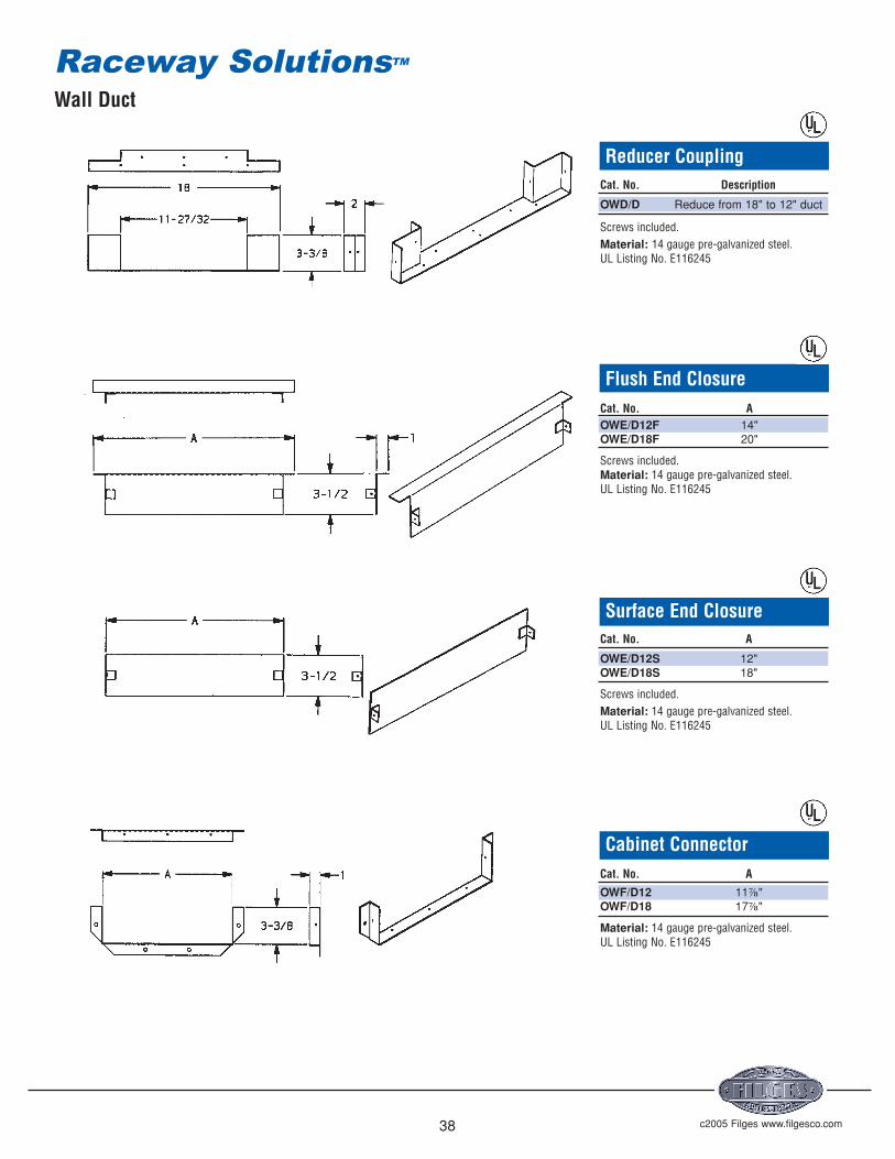
Reducer CouplingCat. No. Description
OWD/D Reduce from 18" to 12" duct
Screws included.Material: 14 gauge pre-galvanized steel.UL Listing No. E116245
Flush End ClosureCat. No. AOWE/D12F 14"OWE/D18F 20"
Screws included.Material: 14 gauge pre-galvanized steel.UL Listing No. E116245
Surface End ClosureCat. No. A
OWE/D12S 12"OWE/D18S 18"
Screws included.Material: 14 gauge pre-galvanized steel.UL Listing No. E116245
Cabinet ConnectorCat. No. A
OWF/D12 11⅞"OWF/D18 17⅞"
Material: 14 gauge pre-galvanized steel.UL Listing No. E116245
Wall Duct
Raceway SolutionsTM

c2005 Filges www.filgesco.com39
Flush 90 °Horizontal ElbowCat. No. A BOWH/D12F 14" 11
⁄"OWH/D18F 20" 17
⁄"
Includes one coupling.
Material: 14 gauge pre-galvanized steel.UL Listing No. E116245
Surface 90 °Horizontal ElbowCat. No. A B
OWH/D12S 12" 11⁄"
OWH/D18S 18" 17⁄"
Includes one coupling.
Material: 14 gauge pre-galvanized steel.UL Listing No. E116245
Flush Internal ElbowCat. No. A B
OWI/D12F 14" 11⁄"
OWI/D18F 20" 17⁄"
Includes one coupling.
Material: 14 gauge pre-galvanized steel.UL Listing No. E116245
Wall Duct
Raceway SolutionsTM
c2005 Filges www.filgesco.com40
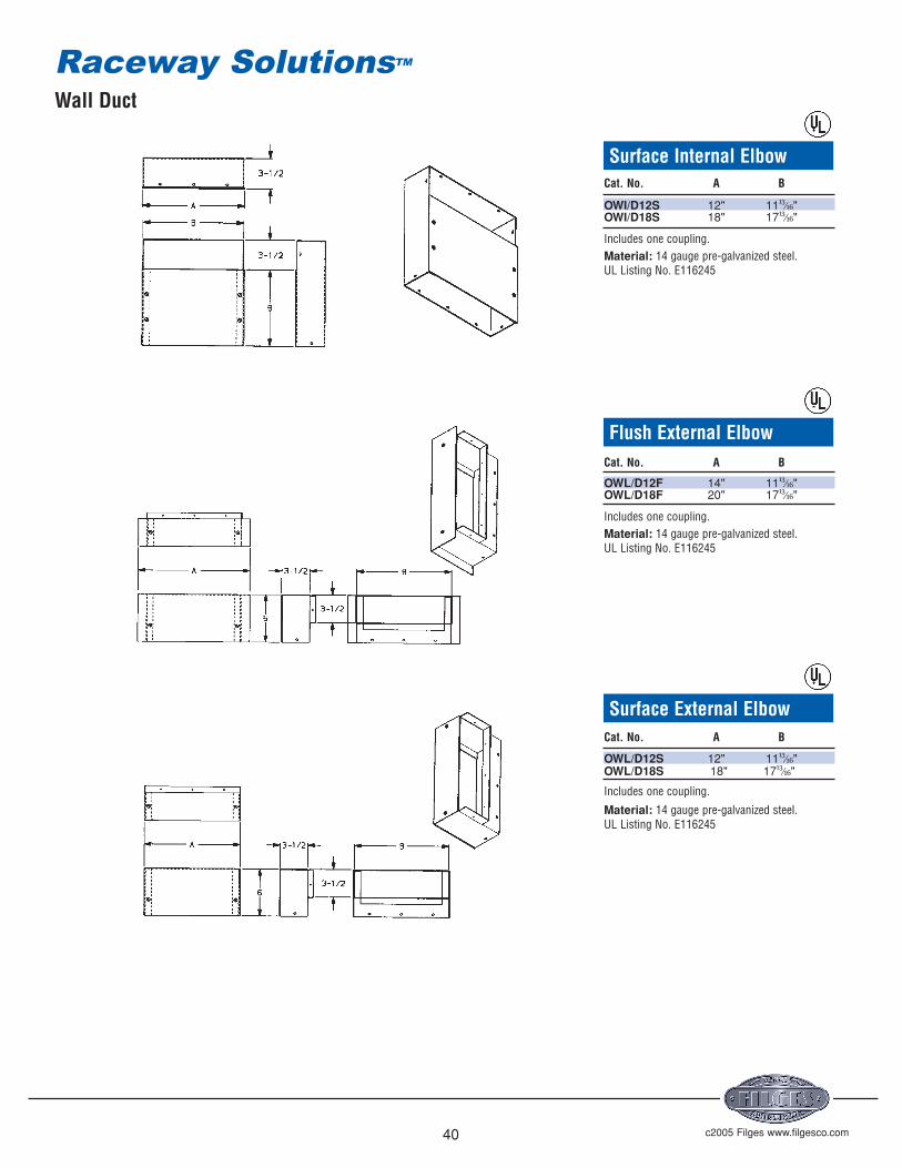
Surface Internal ElbowCat. No. A B
OWI/D12S 12" 11⁄"
OWI/D18S 18" 17⁄"
Includes one coupling.Material: 14 gauge pre-galvanized steel.UL Listing No. E116245
Flush External ElbowCat. No. A B
OWL/D12F 14" 11⁄"
OWL/D18F 20" 17⁄"
Includes one coupling.Material: 14 gauge pre-galvanized steel.UL Listing No. E116245
Surface External ElbowCat. No. A B
OWL/D12S 12" 11⁄"
OWL/D18S 18" 17⁄"
Includes one coupling.
Material: 14 gauge pre-galvanized steel.UL Listing No. E116245
Wall Duct
Raceway SolutionsTM

c2005 Filges www.filgesco.com41
PartitionCat. No. DescriptionOWP/D Internal duct partition
Screws included.Material: 14 gauge pre-galvanized steel.UL Listing No. E116245
Flush Vertical RiserCat.No. A B
OWR/D12F 14" 11⁄"
OWR/D18F 20" 17⁄"
Includes one coupling.Material: 14 gauge pre-galvanized steel.UL Listing No. E116245
Surface Vertical RiserCat. No. A B
OWR/D12S 12" 11⁄"
OWR/D18S 18" 17⁄"
Includes one coupling.
Material: 14 gauge pre-galvanized steel.UL Listing No. E116245
Wall Duct
Raceway SolutionsTM

c2005 Filges www.filgesco.com42
Flush “T ” UnitCat. No. A B C
OWT/D12F 18" 14" 11⁄"
OWT/D18F 24" 20" 17⁄"
Includes one coupling.Material: 14 gauge pre-galvanized steel.UL Listing No. E116245
Surface “T ” UnitCat. No. A B C
OWT/D12S 18" 12" 11⁄"
OWT/D18S 24" 18" 17⁄"
Includes one coupling.
Material: 14 gauge pre-galvanized steel.UL Listing No. E116245
Trench to Wallduct AdapterCat. No. A
OWV/D12 11⅞"OWV/D18 17⅞"
Screws included.Material: 14 gauge pre-galvanized steel.UL Listing No. E116245
Wall Duct
Raceway SolutionsTM

c2005 Filges www.filgesco.com43
Flush “X ” UnitCat. No. A B C
OWX/D12F 18" 14" 11⁄"
OWX/D18F 24" 20" 17⁄"
Includes two couplings.Material: 14 gauge pre-galvanized steel.UL Listing No. E116245
Surface “X ” UnitCat. No. A B C
OWX/D12S 18" 12" 11⁄"
OWX/D18S 24" 18" 17⁄"
Includes two couplings.Material: 14 gauge pre-galvanized steel.UL Listing No. E116245
Wall Duct
Raceway SolutionsTM
Wall Duct Installation Instructions
c2005 Filges www.filgesco.com44
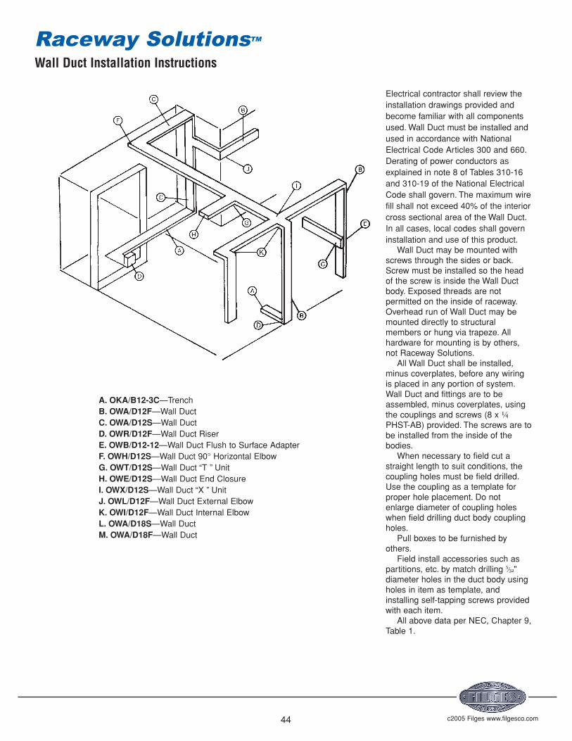
Electrical contractor shall review theinstallation drawings provided andbecome familiar with all componentsused. Wall Duct must be installed andused in accordance with NationalElectrical Code Articles 300 and 660.Derating of power conductors asexplained in note 8 of Tables 310-16and 310-19 of the National ElectricalCode shall govern. The maximum wirefill shall not exceed 40% of the interiorcross sectional area of the Wall Duct.In all cases, local codes shall governinstallation and use of this product.
Wall Duct may be mounted withscrews through the sides or back.Screw must be installed so the headof the screw is inside the Wall Ductbody. Exposed threads are notpermitted on the inside of raceway.Overhead run of Wall Duct may bemounted directly to structuralmembers or hung via trapeze. Allhardware for mounting is by others,not Raceway Solutions.
All Wall Duct shall be installed,minus coverplates, before any wiringis placed in any portion of system.Wall Duct and fittings are to beassembled, minus coverplates, usingthe couplings and screws (8 x ¼PHST-AB) provided. The screws are tobe installed from the inside of thebodies.
When necessary to field cut astraight length to suit conditions, thecoupling holes must be field drilled.Use the coupling as a template forproper hole placement. Do notenlarge diameter of coupling holeswhen field drilling duct body couplingholes.
Pull boxes to be furnished byothers.
Field install accessories such aspartitions, etc. by match drilling
⁄"diameter holes in the duct body usingholes in item as template, andinstalling self-tapping screws providedwith each item.
All above data per NEC, Chapter 9,Table 1.
A. OKA/B12-3C—TrenchB. OWA/D12F—Wall DuctC. OWA/D12S—Wall DuctD. OWR/D12F—Wall Duct RiserE. OWB/D12-12—Wall Duct Flush to Surface AdapterF. OWH/D12S—Wall Duct 90° Horizontal ElbowG. OWT/D12S—Wall Duct “T ” UnitH. OWE/D12S—Wall Duct End ClosureI. OWX/D12S—Wall Duct “X ” UnitJ. OWL/D12F—Wall Duct External ElbowK. OWI/D12F—Wall Duct Internal ElbowL. OWA/D18S—Wall DuctM. OWA/D18F—Wall Duct
Raceway SolutionsTM
Wall Duct Wire Fill Capacity
c2005 Filges www.filgesco.com45
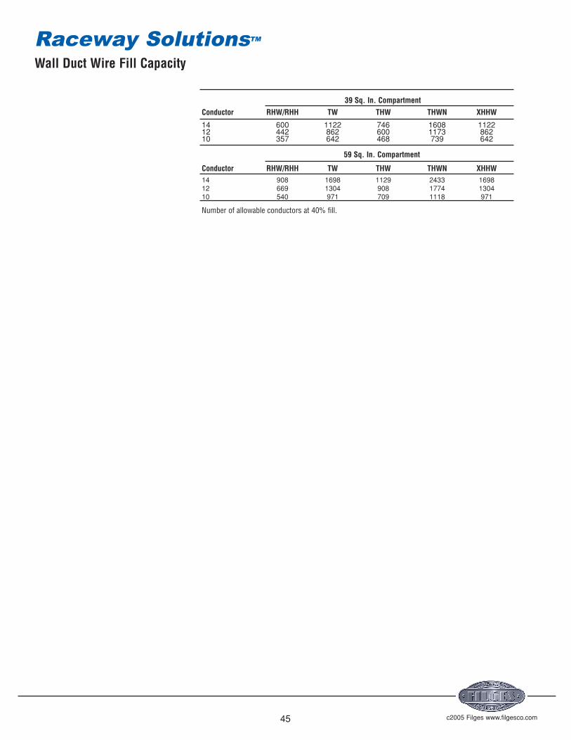
39 Sq. In. CompartmentConductor RHW/RHH TW THW THWN XHHW
14 600 1122 746 1608 112212 442 862 600 1173 86210 357 642 468 739 642
59 Sq. In. Compartment
Conductor RHW/RHH TW THW THWN XHHW14 908 1698 1129 2433 169812 669 1304 908 1774 130410 540 971 709 1118 971
Number of allowable conductors at 40% fill.
Raceway SolutionsTM

c2005 Filges www.filgesco.com
201-1-12 ........................3
201-1-24 ........................3
201-15-12 ......................3
201F-15-12 ....................13
201-15-24 ......................3
201F-15-24 ....................13
201-2-12 ........................3
201F-2-12 ......................13
201-2-24 ........................3
201F-2-24 ......................13
201-3-12 ........................3
201F-3-12 ......................13
201-3-24 ........................3
201F-3-24 ......................13
201-B ............................3, 13
201-DCC........................7, 14
201-DCS........................5, 14
201-ECS ........................6, 14
201-HB90 ......................7, 15
201-JB-1 ........................5
201-JB-15 ......................5, 13
201-JB-2 ........................5, 13
201-JB-3 ........................5, 13
201-JB-4 ........................5
201-UCA........................6, 14
201-VEL ........................6, 15
201W-1-12 ....................3
201W-1-24 ....................3
201W-15-12 ..................3
201WF-15-12 ................13
201W-15-24 ..................3
201WF-15-24 ................13
201W-2-12 ....................3
201WF-2-12 ..................13
201W-2-24 ....................3
201WF-2-24 ..................13
201W-3-12 ....................3
201WF-3-12 ..................13
201W-3-24 ....................3
201WF-3-24 ..................13
201W-B..........................3, 13
201W-DCC ....................7, 14
201W-DCS ....................5, 14
201W-ECS ....................6, 14
201W-HB90 ..................7, 15
201W-JB-1 ....................5
201W-JB-15 ..................5, 13
201W-JB-2 ....................5, 13
201W-JB-3 ....................5, 13
201W-JB-4 ....................5
201W-UCA ....................6, 14
201W-VEL......................6, 15
202-1-12 ........................3
202-1-24 ........................3
202-15-12 ......................3
202F-15-12 ....................13
202-15-24 ......................3
202F-15-24 ....................13
202-2-12 ........................3
202F-2-12 ......................13
202-2-24 ........................3
202F-2-24 ......................13
202-3-12 ........................3
202F-3-12 ......................13
202-3-24 ........................3
202F-3-24 ......................13
202-B ............................3, 13
202-DCC........................7, 14
202-DCS........................5, 14
202-ECS ........................6, 14
202-HB90 ......................7, 15
202-JB-1 ......................5
202-JB-15 ......................5, 13
202-JB-2 ........................5, 13
202-JB-3 ........................5, 13
202-JB-4 ........................5
DAIFA-2G-3 ..................17
202-UCA........................6, 14
202-VEL ........................6, 15
202-UCA........................6, 14
202-VEL ........................6, 15
203-1-12 ........................4
203-1-24 ........................4
203-15-12 ......................4
203-15-24 ......................4
203-2-12 ........................4
203-2-24 ........................4
203-3-12 ........................4
203-3-24 ........................4
203-B ............................4
203-DCC........................7, 14
203-DCS........................5, 14
203-ECS ........................6, 14
203F-15-12 ....................13
203F-15-24 ....................13
203F-2-12 ......................13
203F-2-24 ......................13
203F-3-12 ......................13
203F-3-24 ......................13
203F-B ..........................13
203F-HB90 ....................15
203F-JB-15 ....................13
203F-JB-2 ......................13
203F-JB-3 ......................13
203F-UCA......................14
203F-VEL ......................15
203-HB90 ......................7
203-JB-1 ......................5
203-JB-15 ......................5
203-JB-2 ........................5
203-JB-3 ........................5
203-JB-4 ........................5
203-UCA........................6
203-VEL ........................6
204-1-12 ........................4
204-1-24 ........................4
204-15-12 ......................4
204-15-24 ......................4
204-2-12 ........................4
204-2-24 ........................4
204-3-12 ........................4
204-3-24 ........................4
204-B ............................4
204-HB90 ......................7
204-JB-1 ......................5
204-JB-15 ......................5
204-JB-2 ........................5
204-JB-3 ........................5
204-JB-4 ........................5
204-UCA........................6
204-VEL ........................6
CD-3-12 ........................20
CD-3-24 ........................20
CD-3JF ..........................20
CD-B ..............................20
CD-CC ..........................22
CD-CS ..........................21
CD-CTB ........................20
CD-ES............................21
CD-HB45L ....................22
CD-HB45R ....................22
CD-HB90 ......................22
CD-UCA ........................21
CD-VEL..........................21
CMSF-10 ......................8, 23
DAI-1..............................7
DAI-2..............................7
DAI-3..............................7, 22
DAI-4..............................7
DAIFA-1G-15 ................17
DAIFA-1G-2 ..................17
DAIFA-1G-3 ..................17
DAIFA-2G-15 ................17
DAIFA-2G-2 ..................17
DAIFA-2G-3 ..................17
DAIFA-3G-15 ................17
DAIFA-3G-2 ..................17
IndexCatalog Page Catalog Page Catalog PageNumber Number Number Number Number Number

c2005 Filges www.filgesco.com
JB-CCA-1/2 ........................6, 15
JB-CCA-1-1/2 ....................6, 15
JB-CCA-2 ..........................6, 15
JB-CCA-3/4 ........................6, 15
JB-CCA-B ..........................6, 15
OK/VVW ............................29
OK/VWI ..............................29
OKA/B12-3C ......................26
OKA/B12-4C ......................26
OKA/B9-3C ........................26
OKA/C12-3C ......................26
OKB/B12-3C ......................29
OKB/B12-4C ......................29
OKB/B9-3C ........................29
OKB/C12-3C ......................29
OKC/12-3/4A......................28
OKC/12-3/4C......................28
OKC/9-3/4A........................28
OKC/9-3/4C........................28
OKE/B12 ............................27
OKE/B9 ..............................27
OKE/C12............................27
OKL/B12-3C ......................26
OKL/B12-4C ......................26
OKL/B9-3C ........................26
OKL/C12-3C ......................26
OKR/D12-3C......................29
OKR/D12-4C......................29
OKR/D9-3C........................29
OKSK ................................28
OKT/B12-3C ......................27
OKT/B12-4C ......................27
OKT/B9-3C ........................27
OKT/C12-3C ......................27
OKX/B12-3C ......................27
OKX/B12-4C ......................27
OKX/B9-3C ........................27
OKX/C12-3C ......................27
OWA/D12F ........................37
OWA/D12S ........................37
OWA/D18F ........................37
OWA/D18S ........................37
OWB/D12-12......................37
OWB/D12-18......................37
OWB/D18-12......................37
OWB/D18-18......................37
OWC/D12 ..........................37
OWC/D18 ..........................37
OWD/D ..............................38
OWE/D12F ........................38
OWE/D12S ........................38
OWE/D18F ........................38
OWE/D18S ........................38
DMC-B ..............................7, 22
DMC-Z ..............................7, 22
FACA-1G-AL ....................15
FACA-1G-B ......................15
FACA-1G-BGE ..................15
FACA-1G-BLK ..................15
FACA-1G-GRY ..................15
FACA-2G-AL ....................15
FACA-2G-B ......................15
FACA-2G-BGE ..................15
FACA-2G-BLK ..................15
FACA-2G-GRY ..................15
FACA-3G-AL ....................15
FACA-3G-B ......................15
FACA-3G-BGE ..................15
FACA-3G-BLK ..................15
FACA-3G-GRY ..................15
FAD-CC ............................17
FAD-MC-B ........................17
FAD-MC-Z ........................17
FA-MCP-1/2-2-B................16
FA-MCP-1/2-AL ................16
FA-MCP-1/2-AL ................16
FA-MCP-1/2-B ..................16
FA-MCP-1-1/4-AL..............16
FA-MCP-1-1/4-B................16
FA-MCP-1-AL ....................16
FA-MCP-1-B ......................16
FA-MCP-2-5/8-AL..............16
FA-MCP-2-5/8-B................16
FA-MCP-2-AL ....................16
FA-MCP-2-B ......................16
FA-MCP-3/4-2-AL..............16
FA-MCP-3/4-2-B................16
FA-MCP-3/4-AL ................16
FA-MCP-3/4-B ..................16
FA-MCP-DP-AL ................16
FA-MCP-DP-B ..................16
FA-MCP-FDP-AL ..............16
FA-MCP-FDP-B ................16
FA-MCP-GFCI-B ..............16
FAPCP-BP-BGE................16
FAPCP-BP-BLK ................16
FAPCP-BP-GRY................16
FAPCP-U-BGE..................16
FAPCP-U-BLK ..................16
FAPCP-U-GRY..................16
FATA-AL ............................16
FATA-B ..............................16
FATA-BGE ........................16
FATA-BLK ..........................16
FATA-GRY ........................16
JB-CCA-1 ........................6, 15
OWF/D12..........................38
OWF/D18..........................38
OWH/D12F ......................39
OWH/D12S ......................39
OWH/D18F ......................39
OWH/D18S ......................39
OWI/D12F ........................39
OWI/D12S ........................40
OWI/D18F ........................39
OWI/D18S ........................40
OWL/D12F........................40
OWL/D12S ......................40
OWL/D18F........................40
OWL/D18S ......................40
OWP/D ............................41
OWR/D12F ......................41
OWR/D12S ......................41
OWR/D18F ......................41
OWR/D18S ......................41
OWT/D12F ......................42
OWT/D12S ......................42
OWT/D18F ......................42
OWT/D18S ......................42
OWV/D12 ........................28
OWV/D12 ........................42
OWV/D18 ........................28
OWV/D18 ........................42
OWX/D12F ......................43
OWX/D12S ......................43
OWX/D18F ......................43
OWX/D18S ......................43
PSF-10 ............................8, 23
PSF-10-DR ......................8, 23
PSF-20 ............................8, 23
PSF-20-2DR ....................8, 23
PSF-20-BASE ..................8, 23
PSF-20-BLCOV................8, 23
PSF-20-BLDVP ................8, 23
PSF-20-DUPDVP ............8, 23
PSF-20-DVP139 ..............8, 23
PSF-20-DVP160 ..............8, 23
PSF-20-TELEDVP............8, 23
PSF-21 ............................8, 23
RB-162 ............................7, 22
RB-163 ............................7, 22
IndexCatalog Page Catalog Page Catalog PageNumber Number Number Number Number Number

Dennis Filges Co. Inc.238 Center DriveChicora, PA 16025Phone 724-287-3735Fax 724-285-6212www.filgesco.comEmail: [email protected]
Trench and HospitalWall Duct
Casino Duct
Flush ActivationUnderfloor Duct
ConventionalUnderfloor Duct