rack mount installation and operation manual - aerl sr rack mount user manual … · rack mount...
TRANSCRIPT
aerl USER MANUAL
COOLMAX SR – Rack Mount Australian Energy Research Laboratories
AER05.0013 – G1 v5 25
th January 2015
COOLMAX SR MAXIMIZERTM
RACK MOUNT
Installation and Operation Manual
Models
SRMVR

aerl
USER MANUAL
COOLMAX SR – Rack Mount Australian Energy Research Labs
AER05.0013 – G1.V5 25
th January 2015
1 of 21
Table of Contents
1 WARRANTY .............................................................................................................................................................................. 3
2 SPECIFICATIONS ...................................................................................................................................................................... 4
3 OVERVIEW ................................................................................................................................................................................ 5
4 WHY USE AN MPPT? ................................................................................................................................................................ 5
5 CONNECTOR PINOUT ............................................................................................................................................................... 6
5.1 Power Pin Assignment ................................................................................................................................................................ 6
5.2 Signal Pin Assignment................................................................................................................................................................. 6
5.3 Terminal Board Pinout ................................................................................................................................................................. 7
6 CIRCUIT BREAKERS ................................................................................................................................................................. 7
7 MOUNTING ................................................................................................................................................................................ 8
7.1 Location ..................................................................................................................................................................................... 8
8 INSTALLATION.......................................................................................................................................................................... 8
8.1 Earthing ...................................................................................................................................................................................... 8
8.2 Connections ............................................................................................................................................................................... 9
8.3 Spring Cage Terminal Blocks ...................................................................................................................................................... 9
8.4 Auxiliary Connections ................................................................................................................................................................10
9 CAN COMMUNICATIONS ........................................................................................................................................................ 11
9.1 Can Network Topology .............................................................................................................................................................. 11
9.2 Can Wiring ................................................................................................................................................................................ 11
9.3 Can Connector ..........................................................................................................................................................................12
9.4 SHIELDING ...............................................................................................................................................................................12
9.5 Can Termination ........................................................................................................................................................................13
10 OPERATING GUIDELINES .......................................................................................................................................................14
10.1 Battery Charging Setup .............................................................................................................................................................14
10.2 Temperature Compensation ......................................................................................................................................................15
10.3 Relay Alarm / Genset Control ....................................................................................................................................................15
10.4 Remote On/Off Control ..............................................................................................................................................................16
11 PV ARRAY CONFIGURATION NOTES .....................................................................................................................................16
11.1 Optimal Pv Array Configuration ..................................................................................................................................................16
11.2 Pv Input Blocking Diode ............................................................................................................................................................16
11.3 Pv Module Power Rating And Mounting Considerations ............................................................................................................16
12 TROUBLESHOOTING ..............................................................................................................................................................17
12.1 Low Battery Alarm Triggers Often ..............................................................................................................................................17
12.2 Battery Bank Using Excessive Water (Electrolyte) .....................................................................................................................17
13 APPENDIX A – CAN COMMUNICATIONS PROTOCOL ...........................................................................................................17
13.1 Overview ...................................................................................................................................................................................17
13.2 Coolmax Broadcast Messages ..................................................................................................................................................18
13.3 Coolmax Command Messages ..................................................................................................................................................21

aerl
USER MANUAL
COOLMAX SR – Rack Mount Australian Energy Research Labs
AER05.0013 – G1.V5 25
th January 2015
2 of 21
This Installation Manual contains important safety information and Installation instructions for the AERL COOLMAX SR MAXIMIZER Wall Mount MPPT. The following symbols are used throughout this user manual to indicate ideal Installation methods, potential dangerous conditions and important operational information.
About this Manual
This User Manual provides detailed installation and usage instructions for the COOLMAX SR unit. It
is recommended that all of the Instructions and Cautions in this User Manual be read before begin-ning installation.
Only qualified electricians and technicians should install the COOLMAX SR System. This manual is intended for all Installation technicians and the system owner.
Do not disassemble or attempt to repair the COOLMAX SR unit unless you are a qualified technician and have authority in writing from AERL to do so.
AERL will not be held responsible in any way for the mishandling of this product or for installation of the product in a manner that does not follow the instructions in this manual or as advised by an AERL technician.
Important Indicates information that must be followed to ensure proper operation of the COOLMAX SR unit.
Indicates a critical procedure for the safe Installation of the COOLMAX SR unit. Use extreme
caution when performing this task.
Caution
Important
Important Safety Information

aerl
USER MANUAL
COOLMAX SR – Rack Mount Australian Energy Research Labs
AER05.0013 – G1.V5 25
th January 2015
3 of 21
1 WARRANTY
1. AERL warrants that the Product will be free from manufacturing defects for a period of 24 months from the date of dispatch of the products by AERL to the customer.
2. The Products technical specifications are contained within the Product Datasheet. The Product will conform to the technical specifications contained in the Product Datasheet at the time of dispatch of the Products to the Customer. If the technical specifications as contained in the Product Datasheet are not met, AERL will repair, replace the Product, or refund the amount paid by the Customer in relation to the Product at the Customers option. AERL is under no obligation to provide assistance or advice to the Customer in relation to the technical specifications.
3. The Products must be installed in strict accordance with the Installation Recommendations listed in this Manual.
4. In no event will AERL be liable for:
a) any loss or damage which the Customer suffers arising from, or caused or contributed to by, the Customer's negligence or the negligence of the Customer's agents or servants; and
b) special, indirect or consequential loss or damage as a result of a breach by the Customer of these Standard Terms including, without limitation, loss of profits or revenue, personal injury, death, property damage and the costs of any substitute Products which the Customer obtains.
5. The Product is not covered for damage occurring due to water, including but not limited to condensation, moisture damage and other forms of precipitation.
6. The Product is not covered for damage occurring due to the Product being incorrectly installed or installed in a manner not in accordance with the Installation Recommendations listed in the Product Manual.
7. The Product is not covered for damage occurring due to failure on the part of the customer to operate the product in accordance with the technical specifications as listed in the Product Datasheet.
8. The Product is not covered for damage occurring due to lightning.
9. The Product is not covered for situations where it is used in a manner not specifically outlined in the Product Manual.
10. If any provision in this document is invalid or unenforceable this document will remain otherwise in full force apart from such provision, which will be deemed deleted
Disclaimer: Australian Energy Research Laboratories Pty Ltd, its affiliates, agents, and employees, and all persons acting on its or their behalf (collectively, “AERL”): a) Disclaim any and all liability for any errors, inaccuracies or incompleteness contained in any datasheet or in any other disclosure relating to any product b) Assumes no responsibility or liability for loss or damage whether direct, indirect, consequential or inci-dental, which might arise out of use of such information. The use of any such information will be entirely at the user's risk. c) Reserves the right to change any AERL product, product specifications and data without notice to im-prove
reliability, function or design or otherwise.
Notice of Copyright
AERL COOMAX SR MPPT Solar Charge Controller User Manual Copyright ⓒ2016 all rights reserved. AERL
reserves the right to revise this document and to periodically make changes to the content.

aerl
USER MANUAL
COOLMAX SR – Rack Mount Australian Energy Research Labs
AER05.0013 – G1.V5 25
th January 2015
4 of 21
2 SPECIFICATIONS
CHARACTERISTIC SRMVR
Nominal Battery Voltage - Selectable 24 to 84V
Maximum Output Current 30A
Maximum Recommended PV Array 2500W @ 84Vout(nom) 1500W @ 48Vout (nom) 900W @ 24Vout(nom)
Maximum PV Voltage Open Circuit 180V
Power Conversion Efficiency 99%
Battery Temperature Compensation Yes
Polarity Common Positive
Master/Slave Configurability Yes
Low Battery Alarm/Automatic Low Battery Switch Off Yes
Passive Cooling – no moving parts Yes
Operating Temperature Range -20o to 50+
oC
Storage Temperature -30o to 70
o C
Self Consumption 75mA @ 20V
Data Logging 356 days
Communication Protocol Options CAN
Enclosure type 19” Sub Rack (Indoor Type1)
Weight 2kg
Outer dimensions (L x W x H) 294 x 125 x 92 mm

aerl
USER MANUAL
COOLMAX SR – Rack Mount Australian Energy Research Labs
AER05.0013 – G1.V5 25
th January 2015
5 of 21
3 OVERVIEW
The AERL COOLMAX SR is a high efficiency, buck only, common positive maximum power point tracker. It is the latest development in the MAXIMIZER
TM range, pioneered by AERL in 1985. The SR blends the
famously reliable AERL power stage with easy to use digital features such as system performance logging, fully configurable alarms and remote system monitoring and control.
The COOLMAX SR employs a maximum power point tracking strategy which has been proven to be highly robust, immune to local extrema, and results in power losses of less than 0.5% over the whole operating temperature range of a PV Array.
Increase PV output by approximately 30%
Super high conversion efficiency — 99%
Built-in logging — 1 million sample points
12 months of daily statistic logged internally
Common positive wiring configuration
Passive cooling
CAN bus interface
High power density — 4kW/l & 4kW/kg
Modular subrack mounting design
4 WHY USE AN MPPT?
In simple terms, a Maximum Power Point Tracker sets the voltage of the solar panels to the ideal operating point of the panels. This is the maximum power voltage, or the voltage at which the solar cells can deliver maximum power to the load. This means that by using MPPT technology, the COOLMAX SR can harvest up to 35% more energy from a solar array compared to a non-MPPT regulator.
The bottom line for solar system installers is that a cheaper, less powerful solar array can always be installed when using an MPPT – this saves cost, wiring and solar area. Because the MPPT boosts the panel output by 35%, the required array size and cost is reduced.
The other benefit of MPPT converters is that a high voltage solar array can be converted down to a low voltage battery pack. This is advantageous because solar arrays are designed to be wired in series, and require much lighter wire when doing so. Additionally, a low voltage battery pack is intrinsically safer than a lethal, high voltage pack.

aerl
USER MANUAL
COOLMAX SR – Rack Mount Australian Energy Research Labs
AER05.0013 – G1.V5 25
th January 2015
6 of 21
5 CONNECTOR PINOUT
5.1 POWER PIN ASSIGNMENT
PIN ASSIGNMENT
P1, P2 INPUT NEGATIVE
P3, P4 INPUT POSITIVE
P5, P6 OUTPUT POSITIVE
P7, P8 OUTPUT NEGATIVE
5.2 SIGNAL PIN ASSIGNMENT
PIN ASSIGNMENT FUNCTION ISOLATED
S1 +12V-CAN CAN power YES
S2 CANH CAN signal high YES
S3 TMPCMP For temp comp thermistor NO
S4 GND-CAN CAN ground YES
S5 CANL CAN signal low YES
S6 +3.3V MCU power NO
S7 ALARM+ Alarm relay contact +ve YES
S8 OUTBREAKER Output breaker open/closed sense NO
S9 GND MCU ground NO
S10 ALARM- Alarm relay contact -ve YES
P2 P4 P6 P8
S1 S1 S2 S3
S4 S5 S6
S1
S7 S8 S9
S1
S10 S11 S12
P1 P7 P5 P3

aerl
USER MANUAL
COOLMAX SR – Rack Mount Australian Energy Research Labs
AER05.0013 – G1.V5 25
th January 2015
7 of 21
PIN ASSIGNMENT FUNCTION ISOLATED
S11 ONOFF Remote enable signal NO
S12 INBREAKER Input breaker open/closed sense NO
5.3 TERMINAL BOARD PINOUT
6 CIRCUIT BREAKERS
AERL recommends the use of 6kA, 8kA or 10kA DC rated circuit breakers with an appropriate voltage rating on both input and output. Double or triple ganged circuit-breakers can be connected in series to give the desired voltage rating as shown below.
It is important that the peak voltages are taken into account when selecting breakers. For example a 120V nominal battery pack will be close to 150V at top of charge, so the breaking capability of the circuit breakers will need to be selected accordingly.

aerl
USER MANUAL
COOLMAX SR – Rack Mount Australian Energy Research Labs
AER05.0013 – G1.V5 25
th January 2015
8 of 21
7 MOUNTING
7.1 LOCATION
The COOLMAX SR enclosure is not intended to be mounted where splashing water or direct sunlight can reach the unit.
The terminal board should only be used in dry locations.
Cables should always be routed downwards away from the COOLMAX SR so that moisture which condenses on the cables does not run back into the product.
The COOLMAX SR should be mounted to allow convection airflow to move past the metal enclosure.
If using a version of the COOLMAX SR with a heatsink, it is best practice to mount the Coolmax such that the heatsink fins are in a vertical orientation, so that convection air currents can flow up between them.
8 INSTALLATION
8.1 EARTHING
AERL recommends that the COOLMAX SR MAXIMIZERTM
be utilized in a floating system (no earthing) whenever possible. For very exposed systems, it is recommended that a lightning conductor be provided nearby to prevent damage to PV equipment, batteries and the MAXIMIZER
TM.
Figure 1 - Standard DC breakers with 60V rating per pole are used in triple-gang
configuration to break 180V on the PV side and double gang configuration to break 120V on the output side.
CAUTION: DO NOT EARTH THE ARRAY in any way if a negative earth is used for the
batteries or DC system.

aerl
USER MANUAL
COOLMAX SR – Rack Mount Australian Energy Research Labs
AER05.0013 – G1.V5 25
th January 2015
9 of 21
For systems using Sunpower PV arrays, it is necessary to provide a positive earth for the array.
8.2 CONNECTIONS
Use appropriately rated wire to connect PV input and battery bank output. Check the polarity in the diagram provided in this user's manual.
Install circuit breakers as described in Section 6.
Check the polarity of the input and output with a multimeter before switching on the COOLMAX SR.
8.3 SPRING CAGE TERMINAL BLOCKS
The spring cage terminal blocks are operated with a screwdriver. The recommended part is SZF 3-1,0 x 5,5 manufactured by Pheonix Contact. A flathead screw driver with the same rough dimensions can be used as shown below.
The screwdriver is used to lever the spring cage downwards. This opens the terminal and allows the wire to be inserted.
Figure 2.1 - Dimensions of flathead screwdriver to actuate spring cage
terminals Figure 2.2 - Using the terminal block
CAUTION: Reversing polarity of input or output will cause damage to the COOLMAX SR MAXIMIZER
TM and void product warranty.

aerl
USER MANUAL
COOLMAX SR – Rack Mount Australian Energy Research Labs
AER05.0013 – G1.V5 25
th January 2015
10 of 21
8.4 AUXILIARY CONNECTIONS
The COOLMAX SR has a number of inputs and outputs to add functionality to the product. The correct way to connect these circuits is shown below.
Figure 2.3 - Screwdriver is used to lever down spring cage to allow insertion of wire

aerl
USER MANUAL
COOLMAX SR – Rack Mount Australian Energy Research Labs
AER05.0013 – G1.V5 25
th January 2015
11 of 21
9 CAN COMMUNICTIONS
9.1 CAN NETWORK TOPOLOGY
The CAN bus is structured as a linear network, with short stubs branching from 'T' connectors on the main bus backbone to each device. The CAN bus data lines must be terminated at each end of the main bus with 120 ohm resistors between the CAN-H and CAN-L signals.
The AERL COOLMAX SR CAN connections are implemented with an 'in' and an 'out' connector, therefore placing the 'T' on the device, resulting in a very short fixed-length stub on the circuit board of each device. This is ideal from a signal integrity and network performance point of view.
Multiple COOLMAX SR units can exist on the same CAN bus and this can be connected to other networks using a CAN-Ethernet adaptor.
9.2 CAN WIRING
The CAN data lines (CAN-H and CAN-L) must be implemented with twisted-pair wire for proper data integrity. The wire should have a characteristic impedance of 120 ohms.
Power should also be provided along the CAN cable, ideally with another twisted pair to minimise noise pickup. An overall shield can also be advantageous.
The recommended choice of cable is 7mm Devicenet CANbus 'thin' cable, with 24AWG (data) + 22AWG (power) twisted pairs and a braided shield. Using this cable will result in a robust installation.
Standard CAT5 network cabling (which has an impedance of 100 ohms) can be used, but may become unreliable in longer networks or in the presence of electrical noise from DC/DC converters and other electrical devices in the system.
COOLMAX SR COOLMAX SR CAN/ETHERNET
ADAPTOR
CAN High
CAN Low Termination Resistor
aerl
USER MANUAL
COOLMAX SR – Rack Mount Australian Energy Research Labs
AER05.0013 – G1.V5 25
th January 2015
12 of 21
9.3 CAN CONNECTOR
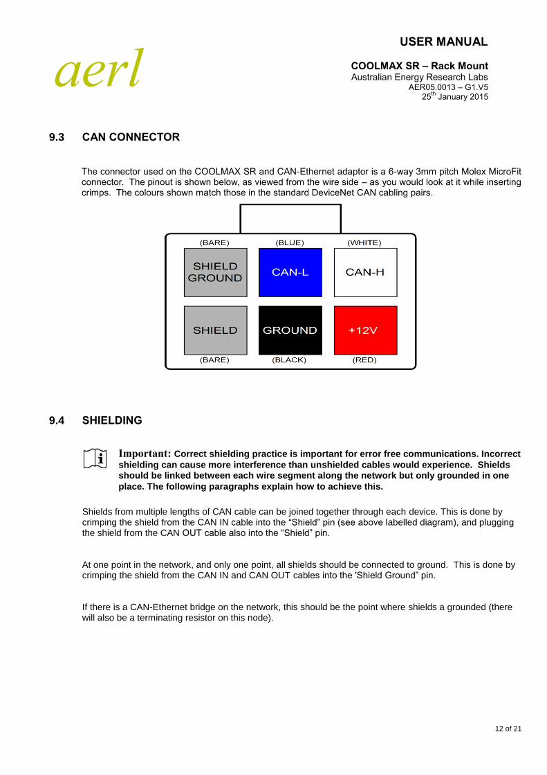
The connector used on the COOLMAX SR and CAN-Ethernet adaptor is a 6-way 3mm pitch Molex MicroFit connector. The pinout is shown below, as viewed from the wire side – as you would look at it while inserting crimps. The colours shown match those in the standard DeviceNet CAN cabling pairs.
9.4 SHIELDING
Shields from multiple lengths of CAN cable can be joined together through each device. This is done by crimping the shield from the CAN IN cable into the “Shield” pin (see above labelled diagram), and plugging the shield from the CAN OUT cable also into the “Shield” pin.
At one point in the network, and only one point, all shields should be connected to ground. This is done by crimping the shield from the CAN IN and CAN OUT cables into the 'Shield Ground” pin.
If there is a CAN-Ethernet bridge on the network, this should be the point where shields a grounded (there will also be a terminating resistor on this node).
Important: Correct shielding practice is important for error free communications. Incorrect
shielding can cause more interference than unshielded cables would experience. Shields should be linked between each wire segment along the network but only grounded in one
place. The following paragraphs explain how to achieve this.

aerl
USER MANUAL
COOLMAX SR – Rack Mount Australian Energy Research Labs
AER05.0013 – G1.V5 25
th January 2015
13 of 21
9.5 CAN TERMINATION
To implement the required 120 Ohm termination resistor at each end of the CAN bus, plug a connector into the unused CAN connector on the last device at each end of the network with a resistor crimped into the appropriate locations.
Coolmax SR
Coolmax SR
Coolmax SR
Can-Ethernet

aerl
USER MANUAL
COOLMAX SR – Rack Mount Australian Energy Research Labs
AER05.0013 – G1.V5 25
th January 2015
14 of 21
10 OPERATING GUIDELINES
10.1 BATTERY CHARGING SETUP
The batteries are charged using an automatic equalise / anti-sulphation charging profile. This profile is designed for lead-acid batteries, which can be equalised automatically by allowing each battery to vent for a short time.
Bulk voltage
Float voltage
Bulk reset voltage
Bulk time
An example charge profile for the Coolmax is shown below to illustrate the charge profile parameters above.
To edit charge profile parameters, refer to the documentation for the COOLMAX SR communication software.
CAUTION: The COOLMAX SR has been specifically designed to charge Lead Acid Batteries and the battery charge profile information detailed below is in relation to charging Lead Acid batteries only.
Installers wishing to use the COOLMAX SR with battery chemistries other than Lead Acid MUST contact AERL to discuss this first prior to any installation and operation of the unit. Failure to do so will void all product warranty.
Important: The charge profile can be edited for other battery chemistries by manipulating the various parameters. However, battery chemistries other than lead acid should be used with extreme caution as there is a high risk of overcharging individual cells. It is always recommended to employ a battery monitoring system as an unbalanced battery pack can result in damage to batteries due to overcharging. Please contact AERL prior to using the COOLMAX SR with battery types other than lead acid to avoid loss of warranty.

aerl
USER MANUAL
COOLMAX SR – Rack Mount Australian Energy Research Labs
AER05.0013 – G1.V5 25
th January 2015
15 of 21
10.2 TEMPERATURE COMPENSATION
Temperature compensation measures the temperature of the batteries and adjusts the float voltage set point to the ideal voltage for batteries at that temperature.
The thermistor is connected as shown in Section 7.4. The Coolmax measures the voltage between TMPCMP+ and GND to determine the temperature of the batteries.
Using the temperature of the batteries, the Coolmax adjusts the float voltage by a user specified factor in millivolts per degrees celcius.
The temperature compensation factor is adjusted using the Coolmax software, refer to its documentation for more information.
10.3 RELAY ALARM / GENSET CONTROL
The ALARM1 and ALARM2 pins are the contacts of an isolated 12V, 1A relay. When an alarm state is in effect, ALARM1 and ALARM2 will be connected inside the Maximizer. When the alarm state is removed, ALARM1 and ALARM2 will be completely disconnected from each other.
An external alarm or genset control circuit can be used to sense whether ALARM1 and ALARM2 are open or closed.
Many different events can be attached to the relay. These are
System init (system starts up after a reset or off period)
Low output voltage warning
Low output voltage fault
Low output voltage genset start
High output voltage fault
High output current fault
High discharge current fault
Input breaker open
Output breaker open
Temperature sensor fault
Regulation fault
Log file full
Panel missing
These are configurable so that multiple faults could trigger the relay. There is also a time hysteresis which prevents the relay from triggering on spurious readings.
To configure the events, consult the documentation for the Coolmax software.

aerl
USER MANUAL
COOLMAX SR – Rack Mount Australian Energy Research Labs
AER05.0013 – G1.V5 25
th January 2015
16 of 21
10.4 REMOTE ON/OFF CONTROL
The remote ON/OFF control can be implemented with a single switch connected between the ONOFF pin and GND pin.
The Coolmax will sense if the ONOFF pin has been connected to GND when the switch closes and this will disable the Maximizer.
11 PV ARRAY CONFIGURATION NOTES
11.1 OPTIMAL PV ARRAY CONFIGURATION
A Maximizer runs at peak efficiency when connected to a PV panel with the minimum recommended open circuit voltage specified in its datasheet.
The input open circuit voltage (Voc) must be above the minimum voltage listed in the datasheet for the Maximizer to run.
11.2 PV INPUT BLOCKING DIODE
A PV Input blocking diode should not be used as long as the open circuit voltage of the PV array is within the range specified by the datasheet for the appropriate Maximizer model and battery voltage. The idea of the blocking diode is to prevent night time reverse leakage from the battery into the PV array. However the diode introduces power wastage during operation which outweighs the leakage, resulting in a net power loss.
11.3 PV MODULE POWER RATING AND MOUNTING CONSIDERATIONS
The nominal power output rating of a particular PV Module is specified bt the PV Module Manufacturer, at One Sun (1000W/sq.m of sunlight radiation) and 25 degees Celcius.
PV Module Maximum Power Voltage (and consequently maximum power) falls off by 4% per every 10 degrees celcius that the PV panel rises above this 25C specification, so typical panel temperatures on a hot summers day of 65C will result in a panel power derating of 16% of the manufacturers rating.
It is best to mount the PV Array in a way that the hot air behind the panels can easily escape via the natural breezes or convection. So don’t mount the PV Array flat against the roof surface, but ensure there is at least 400mm spacing below the panels.
Small gaps (20-30mm) left between adjacent panels are also a good idea to let out the hot air from the sides.
Important: Around 80% of the sun-light energy falling on the solar cells is converted directly into heat, not electricity, and heat is the power output enemy of PV modules.

aerl
USER MANUAL
COOLMAX SR – Rack Mount Australian Energy Research Labs
AER05.0013 – G1.V5 25
th January 2015
17 of 21
12 TROUBLE SHOOTING
12.1 LOW BATTERY ALARM TRIGGERS OFTEN
This could indicate that the PV system is underpowered, never reaching a full 108% equalise value. The battery life will be severely compromised in this situation. The more often the Low Battery Alarm triggers, the more power should be added to the PV array.
Solution: Add more PV modules to the array to increase the power output.
If the array is sufficiently powerful, but the LED is still very often on, check that the Maximizer is set up for the correct voltage of the battery pack. Also check that the Maximizer is charging the battery by checking the output current.
12.2 BATTERY BANK USING EXCESSIVE WATER (ELECTROLYTE)
The battery bank is lightly loaded compared to the input PV power and rarely comes off float voltage. Adjust the float voltage down by a few volts using the COOLMAX SR software.
13 APPENDIX A – CAN COMMUNICATION PROTOCOL
13.1 OVERVIEW
13.1.1 Hardware
The CAN hardware interface used is compatible with the CAN 2.0B standard. The supported bit rates (bits per second) are 1 Mbps, 500 kbps (default), 250 kbps, 125 kbps, 100 kbps and 50 kbps
13.1.2 Software
The CAN protocol uses data frames for most communication. Remote frames are also enabled. All measurement data is transmitted using IEEE single-precision 32-bit format (IEEE 754) with most significant byte (MSB) sent first.
Bit Length 1 11 6 8 Bytes 16 2 7
Start Identifier Control Data Field CRC Ack End
Figure 1. CAN data frame

aerl
USER MANUAL
COOLMAX SR – Rack Mount Australian Energy Research Labs
AER05.0013 – G1.V5 25
th January 2015
18 of 21
13.1.3 Identifier
The identifier field has been split into two sections for the Coolmax SR. Bits 10-5 contain the device identifier and bits 4-0 contains the message identifier associated with that device, as shown in Figure 2.
10 5 4 0
DEVICE IDENTIFIER MESSAGE IDENTIFIER
Figure 2. CAN device identifier address format
13.1.4 Data Field
The data field in all frames is fixed at 8 bytes (64 bits) which allows space for two IEEE 754 32-bit floating point variables as shown in Figure 3. The data field is sent and expected to be received least significant byte first. This allows a direct overlay of a float[2] array and char[8] array on a little endian processor.
High float
s eeeeeeee mmmmmmmmmmmmmmmmmmmmmm
^ ^ ^ ^ ^
63 62 55 54 32
Low float
s eeeeeeee mmmmmmmmmmmmmmmmmmmmmm
^ ^ ^ ^ ^
31 30 23 22 0
Figure 3. Format of the data field in a data frame
13.2 COOLMAX BROADCAST MESSAGES
Data frames containing telemetry values are periodically broadcast onto the bus by the Coolmax.
13.2.1 Identification Information
ID: Coolmax Base Address + 0
Variable Bits Type Description
Serial Number 63 .. 32 Uint32 Device serial number, allocated at manufacture.
Product ID 31 .. 0 Uint32 “A001” stored as a string.

aerl
USER MANUAL
COOLMAX SR – Rack Mount Australian Energy Research Labs
AER05.0013 – G1.V5 25
th January 2015
19 of 21
13.2.2 PV Voltage/Current Measurement
ID: Coolmax Base Address + 1
Variable Bits Type Description
PV Current 63 .. 32 float PV Current
PV Voltage 31 .. 0 float PV Voltage
13.2.3 Output Voltage/Current Measurement
ID: Coolmax Base Address + 2
Variable Bits Type Description
Output Current 63 .. 32 float Output Current
Output Voltage 31 .. 0 float Output Voltage
13.2.4 PV Open Circuit Voltage/Output Charge Measurement
ID: Coolmax Base Address + 3
Variable Bits Type Description
Output charge 63 .. 32 float Output charge
PV OC Voltage 31 .. 0 float PV OC Voltage
13.2.5 PV Power/Battery Temperature Measurement
ID: Coolmax Base Address + 4
Variable Bits Type Description
Battery Temperature 63 .. 32 float Battery Temperature
PV Power 31 .. 0 float PV Power

aerl
USER MANUAL
COOLMAX SR – Rack Mount Australian Energy Research Labs
AER05.0013 – G1.V5 25
th January 2015
20 of 21
13.2.6 Active Flags
ID: Coolmax Base Address + 5
Variable Bits Type Description
Unused 63 .. 13 - -
Panel missing 12 Boolean Input voltage indicates panel missing
Log file full 11 Boolean Log file full
Maximizer fault 10 Boolean Regulation or power stage fault
Variable Bits Type Description
Bat tmp sensor fault 9 Boolean Battery temperature sensor fault
Output breaker open 8 Boolean Output breaker open
Input breaker open 7 Boolean Input breaker open
Hi bat temp 6 Boolean High battery temp fault
Bat current 5 Boolean High battery discharge current fault
Iout fault 4 Boolean High output current fault
Vout high fault 3 Boolean High output voltage fault
Genset start 2 Boolean Low output voltage genset start
Vout low fault 1 Boolean Low output voltage fault
Vout low warning 0 Boolean Low output voltage warning
13.2.7 Time
ID: Coolmax Base Address + 7
Variable Bits Type Description
Time 63 .. 0 Uint64 System unix time

aerl
USER MANUAL
COOLMAX SR – Rack Mount Australian Energy Research Labs
AER05.0013 – G1.V5 25
th January 2015
21 of 21
13.3 COOLMAX COMMAND MESSAGES
13.3.1 Reset Command
ID: Driver Controls Base Address + 23
Variable Bits Units Description
Unused 63..32 Unit32 -
Reset command string
ALL – full reset
RCO – remote config reset
31..0 Uint32 Send 'ALL' or 'RCO' as a string (“00000ALL”) Coolmax replies with Y or N in byte 0