radar set an/tpq-36 (nsn 5840-01-043-4257) and … · tm 11-5840-363-40 technical manual general...
TRANSCRIPT

TM 11-5840-363-40
TECHNICAL MANUAL
GENERAL SUPPORTMAINTENANCE MANUAL
(CARD TEST AND REPAIR)
RADAR SETAN/TPQ-36
(NSN 5840-01-043-4257)AND
RADAR SETAN/TPQ-37(V)
(NSN 5840-01-043-4258)
H E A D Q U A R T E R S , D E P A R T M E N T O F T H E A R M Y24 AUGUST 1982

WARNING PAGE
Solvents used in card repair are flammable. Keep away from heat or open flame. Vapors may beharmful; use with adequate ventilation. Avoid prolonged breathing of vapor. Avoid eye contact. Donot take internally.
To prevent serious burns, use asbestos gloves when handling hot items.

TM 11-5840-363-40C1
CHANGE
NO. 1
HEADQUARTERSDEPARTMENT OF THE ARMYWashington, DC, 11 May 1984
GENERAL SUPPORT MAINTENANCE MANUAL(Card Test and Repair)
FORRADAR SETAN/TPQ-36
(NSN 5840-01-043-4257)AND
RADAR SETAN/TPQ-37(V)
(NSN 5840-01-043-4258)
TM 11-5840-363-40, 24 August 1982, is changed as follows:
1. New or changed material is indicated by a vertical bar in the margin of the page.
2. Added or revised illustrations are indicated by a vertical bar in the margin adjacent to therevised area.
3. Remove old pages and insert new pages as indicated below:
Remove Insert
i thru vi. . . . . . . . . . . . . . . . . . . . . . . . . . . . . . . . . . . . . . . i thru vi3-15 and 3-16 . . . . . . . . . . . . . . . . . . . . . . . . . . . . . . . . 3-15 and 3-16None . . . . . . . . . . . . . . . . . . . . . . . . . . . . . . . . . . . . . . . . . 3-41 and 3-424-1 thru 4-12 . . . . . . . . . . . . . . . . . . . . . . . . . . . . . . . . . 4-1 thru 4-124-13 thru 4-18. . . . . . . . . . . . . . . . . . . . . . . . . . . . . . . . 4-13 thru 4-184-19 thru 4-26. . . . . . . . . . . . . . . . . . . . . . . . . . . . . . . . 4-19 thru 4-264-31 thru 4-242 . . . . . . . . . . . . . . . . . . . . . . . . . . . . . . . 4-31 thru 4-2425-7 and 5-8. . . . . . . . . . . . . . . . . . . . . . . . . . . . . . . . . . . . 5-7 and 5-85-11 and 5-12 . . . . . . . . . . . . . . . . . . . . . . . . . . . . . . . . 5-11 and 5-126-1 thru 6-4 . . . . . . . . . . . . . . . . . . . . . . . . . . . . . . . . . . 6-1 thru 6-4A-1/(A-2 blank). . . . . . . . . . . . . . . . . . . . . . . . . . . . . . . . A-1/(A-2 blank)B-1 and B-2. . . . . . . . . . . . . . . . . . . . . . . . . . . . . . . . . . . B-1 and B-2Index-1 thru lndex-3/(Index-4 blank). . . . . . . . . . . . . . Index-1 thru lndex-3/(Index-4
blank)
4. File this change page in front of this manual.

By Order of the Secretary of the Army:
JOHN A. WICKHAM JR.General, United States Army
Chief of Staff
ROBERT M. JOYCEMajor General, United States Army
The Adjutant General
DISTRIBUTION:To be distributed in accordance with DA Form 12-36B requirements for AN/TPQ-36.
O f f i c a l

TM 11-5840-363-40
SAFETY STEPS TO FOLLOW IF SOMEONEIS THE VICTIM OF ELECTRICAL SHOCK
DO NOT TRY TO PULL OR GRAB THE INDIVIDUAL
IF POSSIBLE , TURN OFF THE ELECTRICAL POWER
IF YOU CANNOT TURN OFF THE ELECTRICALPOWER, PULL, PUSH, OR LIFT THE PERSON TOSAFETY USING A WOODEN POLE OR A ROPE ORSOME OTHER INSULATING MATERIAL
SEND FOR HELP AS SOON AS POSSIBLE
AFTER THE INJURED PERSON IS FREE OFCONTACT WITH THE SOURCE OF ELECTRICALSHOCK, MOVE THE PERSON A SHORT DISTANCEAWAY AND IMMEDIATELY START ARTIFICIALRESUSCITATION
a/(b blank)

TECHNICAL MANUALNo. 11-5840-363-40
CHAPTER 1
CHAPTER 2
TM 11-5840-363-40
HEADQUARTERSDEPARTMENT OF THE ARMY
Washington, DC, 24 August 1982
General SupportMaintenance Manual
(Card Test and Repair)RADAR SETAN/TPQ-36
(NSN 5840-01-043-4257)AND
RADAR SETAN/TPQ-37(V)
(NSN 5840-01-043-4258)
REPORTING ERRORS AND RECOMMENDING IMPROVEMENTS
You can help improve this manual. If you find any mistakes or if youknow of a way to improve the procedures, please let us know. Mail yourletter, DA Form 2028 (Recommended Changes to Publications andBlank Forms), or DA Form 2028-2 located in the back of this manualdirect to: Commander, US Army Communications-ElectronicsCommand and Fort Monmouth, ATTN: DRSEL-ME-MP, Fort Monmouth,New Jersey 07703. A reply will be furnished to you.
HOW TO USE THIS MANUAL . . . . . . . . . . . . . . . . . . . . . . . . . . . . . . . . . . . . .
Scope. . . . . . . . . . . . . . . . . . . . . . . . . . . . . . . . . . . . . . . . . . . . . . . . . . . . . .Maintenance Forms and Records . . . . . . . . . . . . . . . . . . . . . . . . . . . . . . . .Reporting Equipment Improvement Recommendations (EIRs) . . . . . . . .
AN/USM-410(V) TESTER OPERATING ANDMAINTENANCE INSTRUCTIONS . . . . . . . . . . . . . . . . . . . . . . . . .I
AN/USM-410(V) Tester Description . . . . . . . . . . . . . . . . . . . . . . . . . . . . .AN/USM-410(V) Tester Operating Instructions. . . . . . . . . . . . . . . . . . . .AN/USM-410(V) Tester Maintenance Instructions . . . . . . . . . . . . . . . .
I
IPage
ix
1-1
1-11-11-1
2-1
2-12-12-2
Change 1 i
INTRODUCTION . . . . . . . . . . . . . . . . . . . . . . . . . . . . .

CHAPTER 3
Section I
Section II
Section Ill
Section IV
Section V
Section VI
Section VII
ISection Vlll
TEST EQUIPMENT AND ACCESSORIES . . . . . . . . . . . . . . . . . . . . . . . . . . .
General lnformation . . . . . . . . . . . . . . . . . . . . . . . . . . . . . . . . . . . . . . . . . . . . .
Introduction. . . . . . . . . . . . . . . . . . . . . . . . . . . . . . . . . . . . . . . . . . . . . . . . . .Test Equipment and Accessories . . . : . . . . . . . . . . . . . . . . . . . . . . . . . . . .
ID 1 C5000610 Maintenance . . . . . . . . . . . . . . . . . . . . . . . . . . . . . . . . . . . . .
Introduction . . . . . . . . . . . . . . . . . . . . . . . . . . . . . . . . . . . . . . . . . . . . . . . . . .ID 1 C5000610, Schematic. . . . . . . . . . . . . . . . . . . . . . . . . . . . . . . . . . .ID Failure Message . . . . . . . . . . . . . . . . . . . . . . . . . . . . . . . . . . . . . . . . . . . .ID 1 C5000610, Parts List and Parts Location . . . . . . . . . . . . . . . . . . . . .ID 1 C5000610, Wire List. . . . . . . . . . . . . . . . . . . . . . . . . . . . . . . . . . . . . .
1D 2 C5000621 Maintenance . . . . . . . . . . . . . . . . . . . . . . . . . . . . . . . . . . . . .
Introduction. . . . . . . . . . . . . . . . . . . . . . . . . . . . . . . .. . . . . . . . . . . . . . . . . .lD 2 C5000621, Schematic . . . . . . . . . . . . . . . . . . . . . . . . . . . . . . . . . . . .ID Failure Message . . . . . . . . . . . . . . . . . . . . . . . . . . . . . . . . . . . . . . . . . . . .ID 2 C5000621, Parts List and Parts Location . . . . . . . . . . . . . . . . . . . . .lD 2 C5000621, Wire List. . . . . . . . . . . . . . . . . . . . . . . . . . . . . . . . . . . . . .
Test Point Adapter 1 C5000628 Maintenance. . . . . . . . . . . . . . . . . . . . . . . . .
Introduction. . . . . . . . . . . . . . . . . . . . . . . . . . . . . . . . . . . . . . . . . . . . . . . . . .Test Point Adapter 1 C5000628, Schematic.. . . . . . . . . . . . . . . . . . . . .Test Point Adapter 1 C5000628, Parts List and Parts Location . . . . . . .
Test Point Adapter 2 C5000629 Maintenance. . . . . . . . . . . . . . . . . . . . . . . . .
Introduction . . . . . . . . . . . . . . . . . . . . . . . . . . . . . . . . . . . . . . . . . . . . . . . . . .Test Point Adapter 2 C5000629, Schematic. . . . . . . . . . . . . . . . . . . . . .Test Point Adapter 2 C5000629, Parts List and Parts Location . . . . . . .
Test Point Adapter Cable C5000649 Maintenance . . . . . . . . . . . . . . . . . . . . .
Introduction. . . . . . . . . . . . . . . . . . . . . . . . . . . . . . . . . . . . . . . . . . . . . . . . . .Test Point Adapter Cable C5000649, Schematic . . . . . . . . . . . . . . . . . .Test Point Adapter Cable C5000649, Parts List and Parts Location . . .
Test Point Adapter Cable C5000651 Maintenance . . . . . . . . . . . . . . . . . . . . .
Introduction. . . . . . . . . . . . . . . . . . . . . . . . . . . . . . . . . . . . . . . . . . . . . . . . . .Test Point Adapter Cable C5000651 ,Parts List and Parts Location . . .Test Point Adapter Cable C5000651 ,Schematic . . . . . . . . . . . . . . . . . .
Test Point Adapter Cable C5000658 Maintenance . . . . . . . . . . . . . . . . . . . . .
Introduction. . . . . . . . . . . . . . . . . . . . . . . . . . . . . . . . . . . . . . . . . . . . . . . . . .Test Point Adapter Cable C5000658, Parts List and Parts Location . . .Test Point Adapter Cable C5000658, Schematic . . . . . . . . . . . . . . . . . .
Page
3 - 1
3 - 1
3 - 13 - 1
3 - 3
3 - 33 - 33 - 33 - 43 - 6
3-15
3-153-153-153-163-18
3-27
3-273-273-28
3-31
3-313-313-32
3-35
3-353-353-36
3-37
3-373-383 - 3 9
3-41
3-413-423-42
ii Change 1
TM 11-5840-363-40

CHAPTER 4 CARD TEST AND TROUBLESHOOTING . . . . . . . . . . . . . . . . . . . . . .. . . . . . . . . . .
Introduction. . . . . . . . . . . . . . . . . . . . . . . . . . . . . . . . . . . . . . . . . . . . . . . . . .Card Test and Troubleshooting Index . . . . . . . . . . . . . . . . . . . . . . . . . . . .Card Repair Parts Index . . . . . . . . . . . . . . . . . . . . . . . . . . . . . . . . . . . . . . . .Test Equipment and Accessories Index . . . . . . . . . . . . . . . . . . . . . . . . . . .Test Program Index . . . . . . . . . . . . . . . . . . . . . . . . . . . . . . . . . . . . . . . . . . .ID Hookup . . . . . . . . . . . . . . . . . . . . . . . . . . . . . . . . . . . . . . . . . . . . . . . . . . .UUT Hookup. . . . . . . . . . . . . . . . . . . . . . . . . . . . . . . . . . . . . . . . . . . . . . . . .UUT and lD Removal . . . . . . . . . . . . . . . . . . . . . . . . . . . . . . . . . . . . . . . . . .Explanation of Messages. . . . . . . . . . . . . . . . . . . . . . . . . . . . . . . . . . . . . . .UUT Probing. . . . . . . . . . . . . . . . . . . . . . . . . . . . . . . . . . . . . . . . . . . . . . . . .1635841-100 Timing and Reset Card Test and Troubleshooting. . . . .1635842-100 Crowbar Sense Card Test and Troubleshooting . . . . . .1635843-100 HV and RF Sensor Card Test and Troubleshooting . . . .1635845-100 or - 101 HV Area Sense Card Test and
Troubleshooting. . . . . . . . . . . . . . . . . . . . . . . . . . . . . . . . . . . . . . . . . . . .1635846-100 Trigger Control Card Test and Troubleshooting . . . . . .1635847-100 Transmitter Go/No Go Card Test and Troubleshooting1635854-100 Beam Power Supply Control Card Test and
Troubleshooting. . . . . . . . . . . . . . . . . . . . . . . . . . . . . . . . . . . . . . . . . . . .1635870-100 or -101 Phase Shift Driver Card Test and
Troubleshooting. . . . . . . . . . . . . . . . . . . . . . . . . . . . . . . . . . . . . . . . . . . .1635871-100 Phase Shift Computer Card Test and Troubleshooting.1635872-100 Test Driver Card Test and Troubleshooting. . . . . . . . . .1635882-100 B-Scope Video Converter Card Test and
Troubleshooting. . . . . . . . . . . . . . . . . . . . . . . . . . . . . . . . . . . . . . . . . . . .1635883-100 Computer Message Control Card Test and
Troubleshooting. . . . . . . . . . . . . . . . . . . . . . . . . . . . . . . . . . . . . . . . . . . .1635884-100 Clock/TV Sync Generator Card Test and
Troubleshooting. . . . . . . . . . . . . . . . . . . . . . . . . . . . . . . . . . . . . . . . . . . .1635885-100 Cursor/Video Output Card Test and Troubleshooting..1635886-100 B-Scope Video Buffer Card Test and Troubleshooting.1635910-100 Doppler Filter Card Test and Troubleshooting . . . . . . . .1635911-100 Coefficient Generator A Card Test and
Troubleshooting. . . . . . . . . . . . . . . . . . . . . . . . . . . . . . . . . . . . . . . . . . . .1635912-100 Coefficient Generator B Card Test and
Troubleshooting. . . . . . . . . . . . . . . . . . . . . . . . . . . . . . . . . . . . . . . . . . . .1635913-100 Process Cycle Timing Card Test and Troubleshooting .1635914-100 Threshold Crossing Detector Card Test and
Troubleshooting. . . . . . . . . . . . . . . . . . . . . . . . . . . . . . . . . . . . . . . . . . . .
Page
4-1
4 - 14-24 - 44-84-124-184-204-244-264-304-324-344-36
4-384-404-42
4-44
4-464-484-50
4-52
4-54
4-564-584-604-62
4-64
4-664-68
4-70
Change 1 iii
TM 11-5840-363-40

Page
CHAPTER 4 . . . . . . . . . . . . . . . . . . . . . . . .
1635915-100 Target Detector Card Test and Troubleshooting . . . . . .1635916-100 Phase Gain Bias Correction Card Test and
Troubleshooting. . . . . . . . . . . . . . . . . . . . . . . . . . . . . . . . . . . . . . . . . . . .1635917-100 General Purpose Flip-Flop Card Test and
Troubleshooting. . . . . . . . . . . . . . . . . . . . . . . . . . . . . . . . . . . . . . . . . . . .1635918-100 Pulsed interference Detector Card Test and
Troubleshooting. . . . . . . . . . . . . . . . . . . . . . : . . . . . . . . . . . . . . . . . . . . .1635919-100 Target/BITE Buffer Card Test and Troubleshooting . . .1635920-100 1KX24 RAM Card Test and Troubleshooting. . . . . . . .1635921-100 Read Control Card Test and Troubleshooting . . . . . . . .1635922-100 Command Data Card Test and Troubleshooting . . . . . .1635923-100 Collect Cycle Timing Card Test and Troubleshooting..1635924-100 Timing Decoder No.1 Card Test and Troubleshooting.1635925-100 Clock Oscillator Card Test and Troubleshooting . . . . . .1635926-100 Frame Decoder Card Test and Troubleshooting. . . . . . .1635927-100 Data Bus Decoder Card Test and Troubleshooting . . . .1635928-100 MTI Canceller Card Test and Troubleshooting . . . . . . . .1635929-100 Recombiner Card Test and Troubleshooting . . . . . . . . .1635930-100 Signature Generator Card Test and Troubleshooting . .1635931-100 Tri-State Multiplexer Card Test and Troubleshooting. .1635932-100 Receiver Gain Control Card Test and Troubleshooting .1635933-100 RAM Address Generator Card Test and
Troubleshooting. . . . . . . . . . . . . . . . . . . . . ., . . . . . . . . . . . . . . . . . . . . .1635935-100 Differential Driver/Receiver Card Test and
Troubleshooting. . . . . . . . . . . . . . . . . . . . . . . . . . . . . . . . . . . . . . . . . . . .1635936-100 Video Input Multiplex Card Test and Troubleshooting .1635937-100 Power Supply BITE/Buffer Card Test and
Troubleshooting. . . . . . . . . . . . . . . . . . . . . . . . . . . . . . . . . . . . . . . . . . . .1635939-100 General Purpose Register Card Test and
Troubleshooting. . . . . . . . . . . . . . . . . . . . . . . . . . . . . . . . . . . . . . . . . . . .1635940-100 General Purpose Gate Card Test and Troubleshooting.1635941-100 Timing Decoder No. 2 Card Test and Troubleshooting.1635942-100 A/D Converter Card Test and Troubleshooting . . . . . . .1635944-100 or -101 8-MHz Sample and Hold Card Test and
Troubleshooting. . . . . . . . . . . . . . . . . . . . . . . . . . . . . . . . . . . . . . . . . ..1635945-100 A/D Self-Test Card Test and Troubleshooting. . . . . . . .1635946-100 4K RAM Card Test and Troubleshooting . . . . . . . . . . . .1635947-100 Mean Level Select Card Test and Troubleshooting . . . .
4 - 7 2
4 - 7 4
4 - 7 6
4 - 7 84 - 8 04 - 8 24 - 8 44 - 8 64 - 8 84 - 9 04 - 9 24 - 9 44 - 9 64 - 9 84 - 1 0 04 -1024 -1044-106
4 -108
4 -1104 -112
4 -114
4-1164 -1184 -1204-122
4 -1244 -1264 -1284 - 1 3 0
iv Change 1
CARD TEST AND TROUBLESHOOTING (cont)
TM 11-5840-363-40
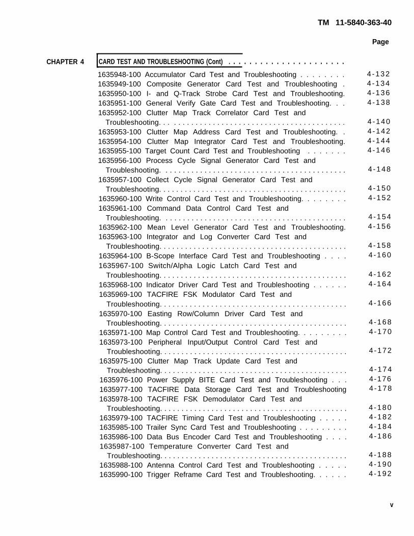
TM 11-5840-363-40
CHAPTER 4 CARD TEST AND TROUBLESHOOTING (Cont) . . . . . . . . . . . . . . . . . . . . . .1635948-100 Accumulator Card Test and Troubleshooting . . . . . . . .1635949-100 Composite Generator Card Test and Troubleshooting .1635950-100 I- and Q-Track Strobe Card Test and Troubleshooting.1635951-100 General Verify Gate Card Test and Troubleshooting. . .1635952-100 Clutter Map Track Correlator Card Test and
Troubleshooting. . . . . . . . . . . . . . . . . . . . . . . . . . . . . . . . . . . . . . . . . . .1635953-100 Clutter Map Address Card Test and Troubleshooting. .1635954-100 Clutter Map Integrator Card Test and Troubleshooting.1635955-100 Target Count Card Test and Troubleshooting . . . . . . .1635956-100 Process Cycle Signal Generator Card Test and
Troubleshooting. . . . . . . . . . . . . . . . . . . . . . . . . . . . . . . . . . . . . . . . . . .1635957-100 Collect Cycle Signal Generator Card Test and
Troubleshooting. . . . . . . . . . . . . . . . . . . . . . . . . . . . . . . . . . . . . . . . . . . .1635960-100 Write Control Card Test and Troubleshooting. . . . . . . .1635961-100 Command Data Control Card Test and
Troubleshooting. . . . . . . . . . . . . . . . . . . . . . . . . . . . . . . . . . . . . . . . . . .1635962-100 Mean Level Generator Card Test and Troubleshooting.1635963-100 Integrator and Log Converter Card Test and
Troubleshooting. . . . . . . . . . . . . . . . . . . . . . . . . . . . . . . . . . . . . . . . . . . .1635964-100 B-Scope Interface Card Test and Troubleshooting . . . .1635967-100 Switch/Alpha Logic Latch Card Test and
Troubleshooting. . . . . . . . . . . . . . . . . . . . . . . . . . . . . . . . . . . . . . . . . . . .1635968-100 Indicator Driver Card Test and Troubleshooting . . . . . .1635969-100 TACFIRE FSK Modulator Card Test and
Troubleshooting. . . . . . . . . . . . . . . . . . . . . . . . . . . . . . . . . . . . . . . . . . . .1635970-100 Easting Row/Column Driver Card Test and
Troubleshooting. . . . . . . . . . . . . . . . . . . . . . . . . . . . . . . . . . . . . . . . . . . .1635971-100 Map Control Card Test and Troubleshooting. . . . . . . . .1635973-100 Peripheral Input/Output Control Card Test and
Troubleshooting. . . . . . . . . . . . . . . . . . . . . . . . . . . . . . . . . . . . . . . . . . . .1635975-100 Clutter Map Track Update Card Test and
Troubleshooting. . . . . . . . . . . . . . . . . . . . . . . . . . . . . . . . . . . . . . . . . . . .1635976-100 Power Supply BITE Card Test and Troubleshooting . . .1635977-100 TACFIRE Data Storage Card Test and Troubleshooting1635978-100 TACFIRE FSK Demodulator Card Test and
Troubleshooting. . . . . . . . . . . . . . . . . . . . . . . . . . . . . . . . . . . . . . . . . . . .1635979-100 TACFIRE Timing Card Test and Troubleshooting . . . . .1635985-100 Trailer Sync Card Test and Troubleshooting . . . . . . . . .1635986-100 Data Bus Encoder Card Test and Troubleshooting . . . .1635987-100 Temperature Converter Card Test and
Troubleshooting. . . . . . . . . . . . . . . . . . . . . . . . . . . . . . . . . . . . . . . . . . . .1635988-100 Antenna Control Card Test and Troubleshooting . . . . .1635990-100 Trigger Reframe Card Test and Troubleshooting. . . . . .
Page
4-1324 -1344 -1364 -138
4 -1404 -1424 -1444 -146
4 -148
4 -1504 -152
4 -1544 -156
4 -1584 -160
4 -1624 -164
4 -166
4 -1684 -170
4 -172
4 -1744-1764 -178
4 -1804 -1824 -1844 -186
4 -1884 -1904 -192
v

CHAPTER 4 CARD TEST AND TROUBLESH00TING (cont) . . . . . . . . . . . . . . . . . . . . . . . . .
1642175-100 Memory Function Interface Card Test andTroubleshooting. . . . . . . . . . . . . . . . . . . . . . . . . . . . . . . . . . . . . . . . . . . .
1642176-100 Arithmetic Register Card Test and Troubleshooting . . .1642177-100 Microsequencer Card Test and Troubleshooting . . . . . .1642178-100 Read Only Memory 1 Card Test and Troubleshooting. .1642179-100 Read Only Memory 2 Card Test and Troubleshooting. .1642180-100 Read Only Memory 3 Card Test and Troubleshooting. .1642181-100 External Register Control Card Test and
Troubleshooting. . . . . . . . . . . . . . . . . . . . . . . . . . . . . . . . . . . . . . . . . . . .1642183-100 External Multiplex Register Card Test and
Troubleshooting. . . . . . . . . . . . . . . . . . . . . . . . . . . . . . . . . . . . . . . . . . . .1642184-100 External Control Card Test and Troubleshooting. . . . . .1642185-100 Program Status Instruction Decoder Card Test and
Troubleshooting. . . . . . . . . . . . . . . . . . . . . . . . . . . . . . . . . . . . . . . . . . . .1642186-100 Fast Multiplier CORDIC Card Test and Troubleshooting1642187-100 I/O Common Data Path Card Test and
Troubleshooting. . . . . . . . . . . . . . . . . . . . . . . . . . . . . . . . . . . . . . . . . . . .1642188-100 I/O Common Control Card Test and Troubleshooting. .1642189-100 Duel Channel Control Card Test and Troubleshooting .1642190-100 Diagnostic Panel Interface Card Test and
Troubleshooting. . . . . . . . . . . . . . . . . . . . . . . . . . . . . . . . . . . . . . . . . . . .1650873-100 External Multiplex Register Card Test and
Troubleshooting. . . . . . . . . . . . . . . . . . . . . . . . . . . . . . . . . . . . . . . . . . . .C500051 1 Phase Shift Computer Card Test and Troubleshooting. . . .SM-D-803125 Data Bus Encoder Card Test and Troubleshooting . . . .SM-D-803128 Data Bus Decoder Card Test and Troubleshooting . . . .SM-D-803137 Temperature Converter Card Test and
Troubleshooting. . . . . . . . . . . . . . . . . . . . . . . . . . . . . . . . . . . . . . . . . . .SM-D-803140 Clock Oscillator Card Test and Troubleshooting. . . . . .SM-D-803146 Tilt Sensor Card Test and Troubleshooting . . . . . . . . . .SM-D-803152 Phase Shifter Driver Card Test and Troubleshooting . .SM-D-803161 Power Supply BITE Card Test and Troubleshooting . . .
4 -1944-1964-1984 -2004-2024 -204
4-206
4 -2104-212
4-2144-216
4-2184 -2204-222
4-224
4-2264-2284-2304-232
4 -2344-2364-2384 -2404-242
CHAPTER 5 CARD REPAIR . . . . . . . . . . . . . . . . . . . . . . . . . . . . . . . . . . . . . . . . . . . . . . . .
Introduction. . . . . . . . . . . . . . . . . . . . . . . . . . . . . . . . . . . . . . . . . . . . . . . . . .Card Repair Overview . . . . . . . . . . . . . . . . . . . . . . . . . . . . . . . . . . . . . . . . .Cleaning Cards . . . . . . . . . . . . . . . . . . . . . . . . . . . . . . . . . . . . . . . . . . . . . .Inspecting Cards. . . . . . . . . . . . . . . . . . . . . . . . . . . . . . . . . . . . . . . . . . . . . .Removing Conformal Coating. . . . . . . . . . . . . . . . . . . . . . . . . . . . . . . . . . .Replacing Bonded Parts. . . . . . . . . . . . . . . . . . . . . . . . . . . . . . . . . . . . . . . .Replacing Card Connector. . . . . . . . . . . . . . . . . . . . . . . . . . . . . . . . . . . . . .Replacing Card Test Point Strip . . . . . . . . . . . . . . . . . . . . . . . . . . . . . . . . .
5 - 1
5 - 15 - 25 - 35 - 45 - 55 - 65 - 1 05 - 1 4
vi Change 1
TM 11-5840-363-40
Page

TM 11-5840-363-40
Page
CHAPTER 5 . . . . . . . . . . . . . . . . . . . . . . . . . . . . . . . . . . . . . . . . . . .
Repairing Conformal Coating . . . . . . . . . . . . . . . . . . . . . . . . . . . . . . . . . . . 5-15Repairing Cards Containing MOS Microelectronic Circuits . . . . . . . . . . . 5-17
CHAPTER 6 ID AND TEST POINT ADAPTER REPAIR . . . . . . . . . . . . . . . . . . . . . . . . . . . .
Introduction . . . . . . . . . . . . . . . . . . . . . . . . . . . . . . . . . . . . . . . . . . . . . . . . . .Repair of Contacts . . . . . . . . . . . . . . . . . . . . . . . . . . . . . . . . . . . . . . . . . . . .Repair of Connector Receptacle . . . . . . . . . . . . . . . . . . . . . . . . . . . . . . . . .Repair of Microcircuits. . . . . . . . . . . . . . . . . . . . . . . . . . . . . . . . . . . . . . . . .Repair of Test Point Adapter Contact . . . . . . . . . . . . . . . . . . . . . . . . . . . .Repair of Test Point Adapter Contacts . . . . . . . . . . . . . . . . . . . . . . . . . . . .
APPENDIX A REFERENCES. . . . . . . . . . . . . . . . . . . . . . . . . . . . . . . . . . . . . . . . . . . . . . . . . .
APPENDIX B EXPENDABLE SUPPLIES AND MATERIALS LIST . . . . . . . . . . . . . . . . . . . . . . .
6 - 1
6 - 16 -26 - 46 -66 -86 - 9
A-1
B-1
vii/(viii blank)
G-1
I-1
CARD REPAIR
GLOSSARY
INDEX

TM 11-5840-363-40
HOW TO USE THIS MANUAL
CONTENT OF MANUAL
This manual contains all of the information that you require for testing, troubleshooting, andrepairing 106 types of cards and assemblies which have been removed from Radar Set AN/TPQ-36 or Radar Set AN/TPQ-37(V).
The manual is divided into six chapters:
● Chapter 1 identifies the scope of the manual and describes how to handle maintenanceforms and records.
● Chapter 2 briefly describes the AN/USM-410(V) tester and tells you where you can findoperating and maintenance instructions for the tester.
● Chapter 3 contains maintenance information (schematic, parts list, parts location, andwire list) for each of the interconnection devices (IDs) and test point adapters.
● Chapter 4 contains the test and troubleshooting procedures for the units under test(UUTS).
● Chapter 5 contains the repair procedures for the UUTS.● Chapter 6 contains the repair procedures for IDs and test point adapter.
HOW TO ACCESS INFORMATION QUICKLY
Pages are numbered consecutively within each chapter. Each page number is prefixed with thechapter number. For example, page 3 of chapter 2 is numbered 2-3. Chapter titles appear on thefront cover of the manual and provide an index for locating the chapters in the manual. Eachchapter title is boxed on the front cover and contains the page number at which the chapter starts.At the right edge of each box is a blackened area. This blackened area matches black markings onthe first page of that chapter of the manual.
THIS CHAPTER IS CONTAINED INTHESE PAGES
THIS CHAPTER IS CONTAINED INTHESE PAGES
In addition, the first page of each chapter contains a chapter index. This index lists the contents ofthe chapter and gives the page numbers of the data.
ix/(x blank)

TM 11-5840-363-40
C H A P T E R 1
I N T R O D U C T I O N
This manual contains general support maintenance instructions to test and repair 105 types ofcards contained in Radar Sets AN/TPQ-36 and AN/TPQ-37(V) using Electronic Equipment RepairFacility OA-8991/USM-410(V).
MAINTENANCE FORMS, RECORDS, AND REPORTS
● Reports of Maintenance and Unsatisfactory Equipment — Department of the Army forms andprocedures used for equipment maintenance will be those prescribed by TM 38-750,The Army Maintenance Management System (TAMMS).
REPORTING EQUIPMENT IMPROVEMENT RECOMMENDATIONS (EIRs)
If your AN/TPQ-36 or AN/TPQ-37(V) cards, test programs, or interconnecting devices needimprovement, let us know. Send us an EIR. You, the user, are the only one who can tell us what youdo not like about your equipment. Let us know why you do not like the design or performance. Putit on an SF 368 (Quality Deficiency Report). Mail it to: Commander, US Army Communications-Electronics Command and Fort Monmouth, ATTN: DRSEL-ME-MP, Fort Monmouth, New Jersey07703. We’ll send you a reply.
1-1/(1-2 blank)
S C O P E

C H A P T E R 2
A N / U S M - 4 1 0 ( V ) T E S T E R O P E R A T I N G A N D
M A I N T E N A N C E I N S T R U C T I O N S
AN/USM-410(V) TESTER DESCRIPTION
Electronic Equipment Test Station AN/USM-410(V) is used for automatic testing and faultisolation of electronic equipment, assemblies, subassemblies, printed circuit boards, andcomponents. This testing and fault isolation is accomplished using a software test program thatdirects the system to provide the proper stimuli to the unit under test (UUT), make measurementsof responses from the UUT, determine the acceptability of the UUT, and fault isolate within theUUT.
The AN/USM-410(V) tester is a computer-controlled automatic test station. It consists of thefollowing major units:
● Tape Station● Control Station● DC Station● UUT Station● Programmable Interface Station● Video Display Terminal (1 terminal)● Printer● RF/Microwave Subsystem
This equipment provides the system functions of control and display, system clock, low frequencyand radio frequency stimulus, measurements, dedicated and programmable UUT interface, andinput power and internal power distribution. The system operates from a 115/200 V, 60-Hz,3-phase power source. See TM 11-6625-2773-12-1 for a detailed description of theAN/USM-410(V) tester.
AN/USM-410(V) TESTER OPERATING INSTRUCTIONS
Operating instructions for the AN/USM-410(V) tester are contained in TM 11-6625-2773-12-1.These instructions include:
●
●
●
●
●
●
●
●
Description of operator controls and indicatorsFull power turn-onNormal power turn-onSystem restartRecovery from loss of powerFull power shutdownNormal power shutdownEmergency shutdown
The procedures in chapter 4 of this manual (TM 11-5840-363-40) contain all operatorinstructions required to test and troubleshoot the UUTs except for the above AN/USM-410(V)tester power turn-on and shutdown procedures.
2-1
TM 11-5840-363-40

TM 11-5840-363-40
AN/USM-410(V) TESTER MAINTENANCE INSTRUCTIONS
Maintenance instructions for the AN/USM-410(V) tester are contained in TM 11-6625-2773-12-1. These instructions include:
● Preventive maintenance● Test● Troubleshooting● Removal and replacement● Parts list
Chapter 3 of this manual (TM 11-5840-363-40) contains the maintenance information requiredto maintain the IDs and test point adapters. Information on how to repair the UUTs is contained inchapter 5. Information on how to repair the IDs and test point adapter is contained in chapter 6.
2-2

TM 11-5840-363-40
C H A P T E R 3
T E S T E Q U I P M E N T A N D A C C E S S O R I E S
Section I . GENERAL INFORMATION
This chapter identifies the test equipment and accessories required to test and troubleshoot cardscontained in Radar Sets AN/TPQ-36 and AN/TPQ-37(V) at the general support level. In addition,information required to maintain the accessories (Interconnecting Device (ID), test point adapter,test point adapter cable, DIP socket plug, and special purpose cable assembly) is provided.
TEST EQUIPMENT AND ACCESSORIES
The following test equipment and accessories are required to test and troubleshoot UUTs at thegeneral support level.
I t e m Description Part Number
1 Electronic Equipment Test Station AN/USM-410(V)
2 Interconnecting Device C5000610
3 Interconnecting Device C5000621
4 Test Point Adapter C5000628
5 Test Point Adapter C5000629
6 Test Point Adapter Cable C5000649
7 DIP Socket Plug (with attached cable) C5000651
8 Special Purpose Electrical Cable Assembly C5000658
9 Test Clip 3781-12(05276)
3-1/(3-2 blank)
I N T R O D U C T I O N

TM 11-5840-363-40
Section Il. ID 1
Introduction. . . . . . . . . . . . . . . . . . . . . . . . . . . . . . . . . . . . ID 1 C5000610, Schematic . . . . . . . . . . . . . . . . . . . . .
ID Failure Message . . . . . . . . . . . . . . . . . . . . . . . . . . . . . .
C 5 0 0 0 6 1 0 M A I N T E N A N C E
Page Page3-3 ID 1 C5000610, Parts List and Parts Location ........ 3-43-3 ID 1 C5000610, Wire List. . . . . . . . . . . . . . . . . . . 3-63-3
This section contains the information required to maintain ID 1 (part number C5000610). Thefollowing maintenance information is provided:
● Schematic●❵ Parts list and parts location● Wire list
ID 1 C5000610, SCHEMATIC
See page FO-1 thru FO-4 for the schematic of ID 1 (part number C5000610).
ID FAILURE MESSAGE
If during execution of a card test program, a failure is detected in the ID, the following message willbe printed out to the operator:
**** END OF PROGRAM ***** ID COOOXXX FAILED *GO-CHAIN=XXXXPCOF: XXXXXXXXXXXX
By using the probable cause of failure (PCOF) and the examples in the following table, thecorrective action can be determined.
PCOF C o r r e c t i v e A c t i o n
U12 ,J3 -26
U1 --SHORT BETWEENPOWER AND GROUND
U7-U9
U1, U2, U3
U2-U9--SHORT ACROSSRELAY COILS
1. Check wiring between J3 Pin 26 and U12. Replace ifrequired.
2. If wiring is okay, replace U12.
Replace U 1.
Replace U7, U8, and U9.
Replace U1, U2, U3.
Replace U2 thru U9.
3-3
I N T R O D U C T I O N

TM 11-5840-363-40
ID 1 C5000610, PARTS LIST AND PARTS LOCATION (1 of 2)
IndexNumber
123456789
1011
12131415161718192 02122232 42526272 8293 03132333 43536373 8
Manufacturer’sCode
5697756977569775697756977569775697796906802058134996906813499690696906969069690681349969068134996906969065697756977969068134956977969065697796906569779690681349969068020556997969065699756997
Part Number
C5000611C5000612C5000613C5000614-1C5000614-2C5000615-1C5000615-2MS51957-45NAS620C8LM24308-2 -5MS51957-5AN960C3LMS35338-134MS35649-224MS51957-30MS35338-136AN960C6LMS39087-3AN960C10LMS35338-138MS51958-64C5000618C5000676-1MS35649-264M24308-2 -15C5000681-1MS51957-51C5000616MS35649-284C5000620MS51957-47AN960C8LMS35649-137NAS620C6LC5000677-1MS51957-31C5000652-1C5000652-2
Description
EnclosurePlate, adapterPlate, mountingConnector receptacleConnector receptacleGuide, circuit cardGuide, circuit cardScrew, machineWasher, flatConnectorScrew, machineWasher, flatWasher, lockNut, hexScrew, machineWasher, lockWasher, flatHandleWasher, flatWasher, lockScrew, machineComponent boardConnector, receptacleNut, hexConnectorBumper, rubberScrew, machineSpacer, bumperNut, hexGuide, connectorScrew, machineWasher, flatWasher, lockWasher, flatConnectorScrew, machineTerminal boardTerminal board
3-4

TM 11-5840-363-40
ID 1 C5OOO61O, PARTS LIST AND PARTS LOCATION (2 of 2)
3-5

TM 11-5840-363-40
ID 1 C5OOO61O, WIRE LIST (1 of 8)
Signal
CH001
RCH001
CH002
CH002
CH002
CH003
CH003
RCH003
CH004
CH004
RCH004
CH005
CH005
RCH005
CH006
CH006
RCH006
CH007
CH007
RCH007
CH008
CH008
RCH008
CH009
CH009
RCH009
CH010
CH010
CH010
CH011
CH011
RCH011
CH012
From
P1-Z1
P1-Z2
J1 -2
P1-Z3
P1-Z3
J1-3
P1-Z5
P1-Z6
J1 -4
P1-Z8
P1-Z9
J1-5
P1-Z10
P1-Z11
J1-6
P1-Z12
P1-Z13
J1-7
P1-Y2
P1-Y1
J1-8
P1-Y4
P1-Y3
J1 -9
P1-Y6
P1-Y5
J1 -10
P1-Y9
P1-Y9
J1-11
P1-Y11
P1-Y10
J1-12
To
J6-56
J6 -76
J2-1
J1-2
J1 -2
J2 -2
J1 -3
TB1-3
J2-3
J1 -4
TB1-4
J2 -4
J1-5
TB1-5
J2-5
J1 -6
TB1-6
J2-6
J1-7
TB1-7
J2-7
J1 -8
TB1-8
J2 -8
J1-9
TB1-9
J2 -9
J1 -10
J1 -10
J2 -10
J1-11
TB1-11
J2-11
Signal
CH012
RCH012
CH013
CH013
RCH013
CH014
CH014
RCH014
CH015
CH015
RCH015
CH016
CH016
RCH016
CH017
CH017
RCH017
CH018
CH018
RCH018
CH019
CH019
RCH019
CH020
CH020
RCH020
CH021
CH021
RCH021
CH022
CH022
RCH022
CH023
From
P1-Y13
F1-Y12
P1-X1
J1 -13
P1-X2
P1-X3
J1 -14
P1-X4
P1-X5
J1-15
P1-X6
P1-X8
J1 -16
P1-X9
P1-X10
J1 -17
P1-X11
P1-X12
J1 -18
P1-X13
P1-W2
J1 -19
P1-W1
P1-W4
J1 -20
P1-W3
P1-W6
J1-21
P1-W5
P1-W9
J1 -22
P1-W8
P1-W11
J1 -12
TB1-12
J1-13
J2 -12
TB1-13
J1 -14
J2 -13
TB1-14
J1 -15
J2 -14
TB1-15
J1 -16
J2-15
TB1-16
J1 -17
J2 -16
TB1-17
J1 -18
J2 -17
TB1-18
J1 -19
J2 -18
TB1-19
J1 -20
J2-19
TB1-20
J1-21
J2 -20
TB1 -21
J1-22
J2-21
TB1-22
J1 -23
3-6
To

TM 11-5840-363-40
CH023
RCH023
CH024
CH024
RCH024
CH025
CH025
RCH025
CH026
CH026
RCH026
CH027
CH027
RCH027
CH028
CH028
RCH028
CH029
CH029
RCH029
CH030
CH030
RCH030
CH031
CH031
RCH031
CH032
CH032
RCH032
CH033
CH033
RCH033
CH034
From
J1-23
P1-W10
P1-W13
J1-24
P1-W12
P1-V1
J1-25
P1-V2
P1-V3
J1-26
P1-V4
P1-V5
J1-27
P1-V6
P1-V8
J1-28
P1-V9
P1-V10
J1-29
P1-V11
P1-V12
J1-30
P1-V13
P1-U2
J1-31
P1-U1
P1-U4
J1-32
P1-U3
P1-U6
J1-33
P1-U5
P1-U9
To
J2-22
TB1-23
J1-24
J2-23
TB1-24
J1-25
J2-24
TB1-25
J1-26
J2-25
TB1-26
J1-27
J2-26
TB1-27
J1-28
J2-27
TB1-28
J1-29
J2-28
TB1-29
J1-30
J2-29
TB1-30
J1-31
J2-30
TB1-31
J1-32
J2-31
TB1-32
J1-33
J2-32
TB1-33
J1-34
Signal
CH034
RCH034
CH035
CH035
RCH035 SH
CH036
CH036
RCH036 SH
CH037
CH037
RCH037
CH038
CH038
RCH038 SH
CH039
CH039
RCH039
CH040
CH040
RCH040
CH041
CH041
RCH041
CH042
CH042
RCH042
CH043
CH043
RCH043 SH
CH044
CH044
RCH044 SH
CH045
From
J1 -34
P1-U8
P1-U11
J1-35
P1-U10
P1-U13
J1-36
P1-U12
P1-S1
J1-37
P1-S2
P1-S3
J1-38
P1-S4
P1-S5
J1-39
P1-S6
P1-S8
J1-40
P1-S9
P1-S10
J1-41
P1-S11
P1-S12
J1-42
P1-S13
P1-R2
J1-43
P1-R1
P1-R4J1-44
P1-R3
P1-R6
To
J2-33
TB1-34
J1-35
J2-34
TB1-35
J1 -36
J2-35
TB1-36
J1 -37
J2 -36
TB1-37
J1 -38
J2-37
TB1-38
J1-39
J2 -38
TB1-39
J1-40
J2-39
TB1-40
J1-41
J2-40
TB1-41
J1-42
J2-41
TB1-42
J1-43
J2-42
TB1-43
J1-44
J2-43
TB1-44
J1-45
3-7
ID 1 C5000610, WIRE LIST (2 of 8)
S i g n a l

TM 11-5840-363-40
ID 1 C5000610, WIRE LIST (3 of 8)
Signal
CH045
RCH045
CH046
CH046
RCH046
CH047
CH047
RCH047
CH048
CH048
CH048
CH048
CH048
CH048
CH048
CH048/077
CH048/077
CH048/077
CH048/077
CH048/077
CH048/077
CH048/077
RCH048/077
CH048A
CH048A
CH048A
CH049
CH049
RCH049 SH
CH050
CH050
RCH050
CH051
3-8
From
J1-45
P1-R5
P1-R9
J1 -46
P1-R8
P1-R11
J1 -47
P1-R10
P1-R13
U6-1
U7-1
U7-8
U8-1
U8-8
U9-1
J1 -77
P1-V14
U7-7
U8-7
U8-7
U9-7
U9-7
TB1-77
J1 -48
J1 -48
P 1 - W 2 6
P1-Q1
J1 -49
P 1 - Q 2
P1-Q3
J 1 - 5 0
P1-Q4
P1-Q5
To
J2 -44
TB1-45
J1 -46
J2-45
TB1-46
J1-47
J2 -46
TB1-47
U6-1
U7-1
U7-8
U8-1
U8-8
U9-1
U9-8
U7-14
U7-7
U7-14
U7-14
U8-14
U8-14
U9-14
U7-6
J2-47
U6-8
U6-8
J1 -49
J2 -48
TB1-49
J1 -50
J2 -49
TB1 -50
J6-37
Signal
RCH051
CH052
CH052
CH052
CH052
CH052
CH052
CH053
CH053
RCH053
CH054
CH054
RCH054
CH055
CH055
RCH055
CH056
CH056
RCH056
CH057
CH057
RCH057
CH058
CH058
RCH058
CH059
CH059
RCH059
CH060
CH060
CH060
CH061
CH061
From
P1-Q6
J1 -52
P1-Q8
P1-Q8
U1-20
U10-14
U11 -14
P1-Q10
J1 -53
P1 -Q11
P1-Q12
J1 -54
P1-Q13
P1-P2
J1 -55
P1-P1
P1-P4
J1 -56
P1-P3
P1-P6
J1-57
P1-P5
P1-P9
J1-58
P1-P8
P1-P11
J1 -59
P1-P10
P1-P13
P1-P13
J1 -60
P1-N1
J1-61
J 6 - 1 7
U1-20
J1 -52
J1 -52
U10-14
U11-14
U12-14
J1 -53
J2-51
TB1-53
J1 -54
J2 -52
TB1-54
J1 -55
J2 -53
TB1-55
J1 -56
J2 -54
TB1-56
J1 -57
J2 -55
TB1-57
J1 -58
J2 -56
TB1-58
J1 -59
J2 -57
TB1 -59
J1 -60
J1 -60
J2 -58
J1-61
J2 -59
To

TM 11-5840-363-40
ID 1 C5OOO61O, WIRE LIST (4 of 8)
RCH061
CH062
CH062
RCH062
CH063
CH063
RCH063
CH064
CH064
RCH064
CH065
CH065
RCH065
CH066
CH066
RCH066
CH067
CH067
RCH067
CH068
CH068
RCH068
CH069
CH069
RCH069
CH070
CH070
RCH070
CH071
CH071
RCH071
CH072
CH072
From
P1-N2
P1-N3
J1-62
P1-N4
P1-N5
J1-63
P1-N6
P1-N8
J1 -64
P1 -N9
P1-N10
J1-65
P1-N11
P1-N12
J1-66
P1-N13
P1-M2
J1-67
P1-M1
P1-M4
J1 -68
P1-M3
P1-M6
J1-69
P1-M5
P1-M9
J1 -70
P1-M8
P1-M11
J1-71
P1-M10
P1-M13
J1-72
To
TB1-61
J1-62
J2 -60
TB1-62
J1-63
J2-61
TB1-63
J1 -64
J2 -62
TB1-64
J1-65
J2-63
TB1-65
J1-66
J2 -64
TB1-66
J1-67
J2-65
TB1-67
J1 -68
J2-66
TB1-68
J1-69
J2-67
TB1-69
J1 -70
J2-68
TB1-70
J1-71
J2-69
TB1-71
J1-72
J2 -70
Signal
RCH072
CH073
CH073
RCH073
CH074
CH074
RCH074
CH075
CH075
RCH075
CH076
CH076
RCH076SH
CH077
CH077
CH077
CH077
CH077
CH077
CH077
CH077
CH078
CH078
RCH078
CH079
RCH079
CH080
RCH080
CH081
CH081
RCH081
CH082
CH082
From
P1-M12
P1-L1
J1-73
P1-L2
P1-L3
J1-74
P1-L4
P1-L5
J1-75
P1-L6
P1-L8
J1-76
P1-L9
P1-L10
U2-2
U3-2
U4-2
U5-2
U6-2
U7-2
U8-2
P1-L12
J1-78
P1-L13
P1-K2
P1-K1
P1-K4
P1-K3
P1-K6
J1-81
P1-K5
P1-K9
J1-82
To
TB1-72
J1-73
J2-71
TB1-73
J1 -74
J2-72
TB1-74
J1-75
J2-73
TB1-75
J1-76
J2 -74
TB1-76
U2-2
U3-2
U4-2
U5-2
U9-2
U7-2
U8-2
U9-2
J1 -78
J2-76
TB1-78
J1-79
TB1-79
J1 -80
TB1-80
J1-81
J2-77
TB1-81
J1-82
J2-78
3-9
Signal

TM 11-5840-363-40
ID 1 C5000610, WIRE LIST (5 of 8)
Signal
RCH082
CH083
CH083
RCH083
CH084
CH084
RCH084
CH085
CH085
RCH085 SH
CH086
CH086
RCH086 SH
CH087
RCH087
CH088
RCH088 SH
CH089
RCH089 SH
CH090
RCH090
CH091
RCH091
CH092
RCH092
CH093
RCH093 SH
CH094
RCH094 SH
CH095
RCH095
CH096
RCH096
From
P1-K8
P1-K1 1
J1-83
P1-K10
P1-K13
J1 -84
P1-K12
P1-J1
J1-85
P1-J2
P1-J3
J1 -86
P1-J4
P1-J5
P1-J6
P1-J8
P1-J9
P1-J10
P1-J11
P1-J12
P1-J13
P1-H2
P1-H1
P1-H4
P1-H3
P1-H6
P1-H5
P1-H9
P1-H8
P1-H11
P1-H10
P1-H13
P1-H12
To
TB1-82
J1-83
J2 -79
TB1-83
J1 -84
J2 -80
TB1-84
J1 -85
J2 -50
TB1-85
J1 -86
J2 -75
TB1-86
J1-87
TB1-87
J1 -88
TB1-88
J1 -89
TB1-89
J1 -90
TB1-90
J1-91
TB1-91
J1 -92
TB1-92
J1-93
TB1-93
J1 -94
TB1-94
J1-95
TB1-95
J1-96
TB1-96
Signal
CH097
RCH097
CH098
CH098
CH099
RCH099 SH
CH100
RCH100
CH101
RCH101
CH102
RCH102
CH103
RCH103
CH104
RCH104
CH105
RCH105
CH106
RCH106
CH107
RCH107
CH108
RCH108
CH109
RCH109
CH110
RCH110
CH111
RCH111
CH112
RCH112
CH113
From
P1-G1
P1-G2
P1-G3
P1-G3
P1-G5
P1-G6
P1-G8
P1-G9
P1-G10
P1-G11
P1-G12
P1-G13
P1-E2
P1-E1
P1-E4
P1-E3
P1-E6
P1-E5
P1-E9
P1-E8
P1 -E11
P1-E10
P1-E13
P1-E1 2
P1-D1
P1-D2
P1-D3
P1-D4
P1-D5
P1-D6
P1-D8
P1-D9
P1-010
To
J1-97
TB1-97
J1-98
J1 -98
J1 -99
TB1-99
J1 -100
TB1-100
J6-1
J6-21
J6-41
J6-61
J6 -22
J6 -2
J6 -77
J6 -57
J6-3
J6-23
J6-43
J6 -63
J6 -24
J6 -4
J6 -64
J6 -44
J6-5
J6-25
J6-45
J6-65
J6-26
J6-6
J6 -66
J6-46
J 6 - 7
3-10

TM 11-5840-363-40
ID 1 C5000610, WIRE LIST (6 of 8)
Signal
RCH113
CH114
CH114
CH114
RCH114
CH114A
CH114A
CH114A
RCH114A
CH115
RCH115
CH116
RCH116
CH117
RCH117
CH118
RCH118
CH119
RCH119
CH120
RCH120
CH121
RCH121
CH122
RCH122
CH123
RCH123
CH124
RCH124
CH125
CH125
CH125
CH125
From
P1-D11
P1-D12
U1-2
U3-7
P1-D13
J6 -47
P1-W22
U2-8
J6 -67
P1-C2
P1-C1
P1-C4
P1-C3
P1-C6
P1-C5
P1-C9
P1-C8
P1-C11
P1-C10
P1-C13
P1-C12
P1-B1
P1-B2
P1-B3
P1-B4
P1-B5
P1-B6
P1-B8
P1-B9
P1-B10
U1-17
U4-1
U5-7
To
J6-27
U2-1
U1-1
U1-2
U2-6
U3-8
U2-8
U3-8
U4-6
J6 -28
J6 -8
J6 -68
J6 -48
J6 -50
J6 -70
J6-31
J6-11
J6-71
J6-51
J6 -18
J6 -38
J6 -52
J6 -72
J6-33
J6 -13
J6-73
J6-53
J6 -14
J6 -34
U4-1
U1-19
U5-1
U1-17
Signal
RCH125
CH125A
CH125A
CH125A
RCH125A
CH126
RCH126
CH127
RCH127
CH128
RCH128
CH1001
CH1001
RCH1001
CH1002
CH1002
RCH1002
CH1003
CH1003
RCH1003
CH1006
CH1006
RCH1006
CH1008
CH1008
RCH1008
CH1009
CH1009
RCH1009
CH1010
CH1010
RCH1010
CH1011
From
P1-B11
J6 -54
P1-W24
U4-8
J6 -74
P1-B12
P1-B13
P1-A2
P1-A1
P1-A4
P1-A3
J3-1
P1-Z14
P1-Z15
J3 -2
P1-Z16
P1-Z17
J3-3
P1-Z18
P I - Z 1 9
J3 -4
P1-Z25
P1-Z26
J3-5
P1-Y17
P1-Y16
J3-6
P1-Y19
P1-Y18
J3-7
P 1 Y 2 2
P1-Y21
J3 -9
To
U5-6
U5-8
U4-8
U5-8
U9-6
J6-35
J6-15
J6 -75
J6-55
J6 -16
J6 -36
U10-1
J3-1
TB2-1
U10-2
J3 -2
TB2-2
U10-3
J3-3
TB2-3
U10-4
J3 -4
TB2-4
U10-5
J3-5
TB2-5
U10-6
J3 -6
TB2-6
U10-13
J3-7
TB2-7
U10-12
3-11

TM 11-5840-363-40
ID 1 C5000610, WIRE LIST (7 of 8)
Signal
CH1011
RCH1011
CH1012
CH1012
RCHI012
CH1013
CH1013
RCH1013
CH1014
CH1014
RCH1014
CH1015
CH1015
RCH1015
CH1016
CH1016
RCH1016
CH1017
CH1017
RCH1017
CH1021
CH1021
RCH1021
CH1042
CH1042
RCH1042
CH1043
CH1043
RCH1043
CH1044
CH1044
RCH1044
CH1046
From
P1-Y24
P1-Y23
J3 -10
P1-Y26
P1-Y25
J3-11
P1-X14
P 1 - X l 5
J3 -12
P1-X16
P 1 - X l 7
J3 -13
P1-X18
P1-X19
J3 -14
P1-X21
P1-X22
J3-15
P1-X23
P1-X24
J3 -16
P1-W19
P1-W18
J3-17
P1-S25
P1-S26
J3 -18
P1-R15
P1-R14
J3 -19
P1-R17
P1-R16
J3 -20
To
J3 -9
TB2-9
U10-11
J3 -10
TB2-10
U10-10
J3-11
TB2-11
U10-9
J3 -12
TB2-12
U10-8
J3 -13
TB2-13
U10-7
J3 -14
TB2-14
U11-1
J3-15
TB2-15
U11-2
J3 -16
TB2-16
U11-3
J3-17
TB2-17
U11-4
J3 -18
TB2-18
U11-5
J3 -19
TB2-19
U11-6
Signal
CH1046
RCH1046
CH1047
CH1047
RCH1047
CH1048
CH1048
RCH1048
CH1050
CH1050
RCH1050
CH1051
RCH1051
CH1057
CH1057
RCHl057
CH1060
CH1060
RCH1060
CH1061
CH1061
RCH1061
CH1062
CH1062
RCH1062
CH1063
CH1063
RCH1063
CH1064
CH1064
RCH1064
CH1065
CH1065
From
P1-R22
P1-R21
J3-21
P1-R24
P1-R23
J3-22
P1-R26
P1-R25
J3 -23
P1-Q16
P1-Q17
P1-Q18
P1-Q19
J3-25
P1-P19
P1-P18
J6 -62
P1-P26
P1-P25
J3-32
P1-N14
P1-N15
J3 -28
P1-N16
P1-N1 7
J3 -27
P1-N18
P1-N19
J3-29
P1-N21
P1-N22
J3 -30
P1-N23
J3 -20
TB2-20
U11-13
J3-21
TB2-21
U11-12
J3 -22
TB2-22
U11-11
J3 -23
TB2-23
J6 -58
J6 -78
U11-10
J3 -25
TB2-25
U12-5
J6 -62
J6 -42
U11-9
J3 -32
TB2-32
U11-8
J3 -28
TB2-28
U11-7
J3-27
TB2-27
U12-1
J3-29
TB2-29
U12-2
J3 -30
3-12
To
TM 11-5840-363-40
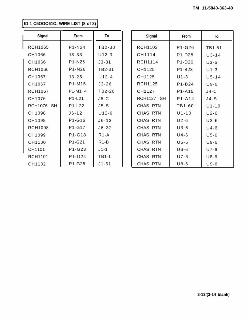
ID 1 C5OOO61O, WIRE LIST (8 of 8)
Signal
RCH1065
CH1066
CH1066
RCH1066
CH1067
CH1067
RCH1067
CH1076
RCH1076 SH
CH1098
CH1098
RCH1098
CH1099
CH1100
CH1101
RCH1101
CH1102
From
P1-N24
J3 -33
P1-N25
P1-N26
J3 -26
P1-M15
P1-M1 4
P1-L21
P1-L22
J6 -12
P1-G16
P1-G17
P1-G18
P1-G21
P1-G23
P1-G24
P1-G25
To
TB2-30
U12-3
J3-31
TB2-31
U12-4
J3-26
TB2-26
J5-C
J5-S
U12-6
J6 -12
J6 -32
R1-A
R1-B
J1-1
TB1-1
J1-51
Signal
RCH1102
CH1114
RCH1114
CH1125
CH1125
RCH1125
CH1127
RCH1127 SH
CHAS RTN
CHAS RTN
CHAS RTN
CHAS RTN
CHAS RTN
CHAS RTN
CHAS RTN
CHAS RTN
CHAS RTN
From
P1-G26
P1-D25
P1-D26
P1-B23
U1-3
P1-B24
P1-A15
P1-A14
TB1-60
U1-10
U2-6
U3-6
U4-6
U5-6
U6-6
U7-6
U8-6
To
TB1-51
U3-14
U3-6
U1-3
U5-14
U9-6
J4-C
J4-S
U1-10
U2-6
U3-6
U4-6
U5-6
U9-6
U7-6
U8-6
U9-6
3-13/(3-14 blank)

TM 11-5840-363-40
Section I l l . ID 2 C5000621 MAINTENANCE
Page PageIntroduction. . . . . . . . . . . . . . . . . . . . . . . . 3-15 ID 2 C5000621, Parts List and Parts Location . 3-16ID 2 C5000621, Schematic . . . . . . . . . . . . . . . . . . 3-15 ID 2 C5000621, Wire List. . . . . . . . . . . . . . 3-18ID Failure Message . . . . . . . . . . . . . . . . . . . . . 3-15
This section contains the information required to maintain ID 2 (part number C5000621 ). Thefollowing maintenance information is provided:
● Schematic● Parts list and parts location● Wire list
ID 2 C5000621, SCHEMATIC
See page FO-5 thru FO-8 for the schematic of ID 2 (part number C5000621).
ID FAILURE MESSAGE
during execution of a card test program, a failure is detected in the ID, the following message willbe printed out to the operator:
**** END OF PROGRAM ***** ID C5000XXX FAILED *GO-CHAIN=XXXXPCOF: XXXXXXXXXXXX
B y u s i n g t h e p r o b a b l e c a u s e o f f a i l u r e ( P C O F ) a n d t h ecorrective action can be determined.
IPCOF I Corrective Action
U1 , J3-4 1. Check wiring between J3 Pin 4 and U1 . Replace ifrequired.
2. If wiring is okay, replace U1.
Change 1 3-15
INTRODUCTION

TM 11-5840-363-40
ID 2 C5000621, PARTS LIST AND PARTS LOCATION (1 OF 2 )
IndexNumber
123456789
101112131415161718192 02122232 4252 6272 8293 031323 33 43536373839
Manufacturer’sCode
5697756977569775697756977569779 6 9 0 6802058 1 3 4 996906813499 6 9 0 696906969069 6 9 0 6813499690681349969069690656977569779 6 9 0 681349569779690656977969065697796906813499690680205569979690656997569978134981349
Part Number
C5000611C5000612C5000613C5000614-1C5000615-1C5000615-2MS51957-45NAS620C8LM24308-2 -5MS51957-5AN960C3LMS35338-134MS35649-224MS51957-30MS35338-136AN960C6LMS39087-3AN960C10LMS35338-138MS51958-64C5000618C5000676-1MS35649-264M24308-2 -15C5000681-1MS51957-51C5000616MS35649-284C5000620MS51957-47AN960C8LMS35338-137NAS620C6LC5000677-1MS51957-31C5000652-1C5000652-2M39024-10-03M39024-10 -02
Description
EnclosurePlate, adapterPlate, mountingConnector, receptacleGuide, circuitcardGuide, circuit cardScrew, machineWasher,f latConnectorScrew,machineWasher,f latWasher,lockNut,hexScrew, machineWasher,lockWasher,f latHandleWasher,f latWasher,lockScrew, machineComponent boardConnecton receptacleNut,hexConnectorBumper,rubberScrew, machineSpacer,bumperNut,hexGuide, connectorScrew, machineWasher,f latWasher,lockWasher,f latConnectorScrew, machineTerminal boardTerminal boardConnector test point (black)Connecton,testpoint (red)
3-16
TM 11-5840-363-40
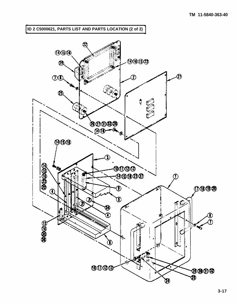
-ID 2 C5000621, PARTS LIST AND PARTS LOCATION (2 of 2)
3-17

TM 11-5840-363-40
ID 2 C5000621, WIRE LIST (1 of 8)
Signal
CH001
CH001
CH001
CH001
RCH001
CH002
CH002
CH002
CH003
CH003
RCH003
CH004
CH004
RCH-1004
CH005
CH005
RCH005
CH006
CH006
RCH006
CH-1007
CH007
RCH007
CH008
CH008
RCH008
CH009
CH009
RCH009
CH010
CH010
CH010
CH011
From
P1-Z1
J1-1
TP1
TP1
P1-Z2
P1-Z3
P1-Z3
J1-2
J1-3
P1-Z5
P1-Z6
J1 -4
P1-Z8
P1-Z9
J1-5
P1-Z10
P1-Z11
J1-6
P1-Z12
P1-Z13
J1-7
P1-Y2
P1-Y1
J1-8
P1-Y4
P1-Y3
J1-9
P1-Y6
P1-Y5
J1-10
P1-Y9
P1-Y9
J1-11
To
J2-1
J2-1
J1-1
J1-1
TB1-1
J1-2
J1 -2
J2-1
J2-3
J1-3
TB1-3
J2 -4
J1 -4
TB1-4
J2-5
J1-5
TB1-5
J2-6
J1-6
TB1-6
J2-7
J1-7
TB1-7
J2-8
J1-8
TB1-8
J2-9
J1-9
TB1-9
J2 -10
J1 -10
J1 -10
J2-11
Signal
CH011
RCH011
CH012
CH012
RCH012
CH013
CH013
RCH013
CH014
CH014
RCH014
CH015
CH015
RCH015
CH016
CH016
RCH016
CH017
CH017
RCH017
CH018
CH018
RCH018
CH019
CH019
RCH019
CH020
CH020
RCH020
CH021
CH021
RCH021
CH022
From
P1-Y11
P1-Y10
J1 -12
P1-Y13
P1-Y12
P1-X1
J1 -13
P1-X2
P1-X3
J1 -14
P1-X4
P1-X5
J1-15
P1-X6
P1-X8
J1-16
P1-X9
P1-X10
J1-17
P1-X11
P1-X12
J1 -18
P1-X13
P1-W2
J1-19
P1-W1
P1-W4
J1 -20
P1-W3
P1-W6
J1-21
P1-W5
P1-W9
To
J1-11
TB1-11
J2-12
J1-12
TB1-12
J1-13
J2-13
TB1-13
J1 -14
J2 -14
TB1-14
J1-15
J2-15
TB1-15
J1-16
J2 -16
TB1-16
J1-17J2-17
TB1-17
J1-18
J2 -18
TB1-18
J1-19
J2-19
TB1-19
J1 -20
J2-20
TB1-20
J1-21
J2-21
TB1-21
J1-22
3-18

TM 11-5840-363-40
I D 2 C5000621, WIRE LIST (2 of 8)
CH022
RCH022
CH023
CH023
RCH023
CH024
CH024
RCH024
CH025
CH025
RCH025
CH026
CH026
RCH026
CH027
CH027
RCH027
CH028
CH028
RCH028
CH029
CH029
RCH029
CH030
CH030
RCH030
CH031
CH031
RCH031
CH032
CH032
RCH032
CH033
From
J1-22
P1-W8
P1-W11
J1-23
P1-W10
P1-W13
J1 -24
P1-W12
P1-V1
J1-25
P1-V2
P1-V3
J1-26
P1-V4
P1-V5
J1-27
P1-V6
P1-V8
J1-28
P1-V9
P1-V10
J1 -29
P1-V11
P1-V12
J1 -30
P1-V13
P1-U2
J1-31
P1-U1
P1-U4
J1-32
P1-U3
P1-U6
To
J2-22
TB1-22
J1-23
J2-23
TB1-23
J1 -24
J2 -24
TB1-24
J1-25
J2-25
TB1-25
J1-26
J2-26
TB1-26
J1-27
J2-27
TB1-27
J1-28
J2 -28
TB1-28
J1 -29
J2 -29
TB1-29
J1 -30
J2 -30
TB1-30
J1-31
J2-31
TB1-31
J1-32
J2-32
TB1-32
J1-33
Signal
CH033
RCH033
CH034
CH034
RCH034
CH035
CH035
RCH035 SH
CH036
CH036
RCH036 SH
CH037
CH037
RCH037
CH038
C H 0 3 8
RCH038 SH
C H 0 3 9
C H 0 3 9
RCH039
C H 0 4 0
C H 0 4 0
C H 0 4 0
C H 0 4 1
C H 0 4 1
RCH041
C H 0 4 2
C H 0 4 2
RCH042
C H 0 4 3
C H 0 4 3
RCH043 SH
C H 0 4 4
From
J1-33
P1-U5
P1-U9
J1 -34
P1-U8
P1-U11
J1-35
P1-U10
P1-U13
J1-36
P1-U12
P1-S1
J1-37
P1-S2
P1-S3
J1-38
P1-S4
P1-S5
J1 -39
P1-S6
P1-S8
J1 -40
P1-S9
P1-S10
J1-41
P1-S11
P1-S12
J1-42
P1-S13
P1-R2
J1-43
P1-R1
P1-R4
To
J2-33
TB1-33
J1 -34
J2 -34
TB1-34
J1-35
J2-35
TB1-35
J1-36
J2-36
TB1-36
J1-37
J2-37
TB1-37
J1-38
J2-38
TB1-38
J1-39
J2-39
TB1-39
J1 -40
J2 -40
TB1-40
J1-41
J2-41
TB1-41
J1-42
J2-42
TB1-42
J1-43
J2-43
TB1-43
J1 -44
3-19
Signal

TM 11-5840-363-40
ID 2 C5000621, WIRE LIST (3 of 8)
Signal
CH044
RCH044 SH
CH045
CH045
RCH045
CH046
CH046
RCH046
CH047
CH047
RCH047
CH048
CH048
CH048
CH048
CH048
CH049
CH049
RCH049 SH
CH050
CH050
RCH050
CH051
CH051
RCH051
CH052
CH052
CH052
CH052
CH053
CH053
RCH053
CH054
From
J1 -44
P1-R3
P1-R6
J1-45
P1-R5
P1-R9
J-146
P1-R8
P1-R11
J1-47
P1-R10
P1-R13
P1-R13
J1-48
TP2
TP2
P1-Q1
J1 -49
P1-Q2
P1-Q3
J1 -50
P1-Q4
P1-Q5
J 1 - 5 1
P1-Q6
P1-Q8
P1-Q8
U1-14
U2-14
P1-Q10
J1-53
P1-Q11
P1-Q12
To
J2 -44
TB1-44
J1-45
J2-45
TB1-45
J1-46
J2-46
TB1-46
J1-47
J2-47
TB1-47
J1-48
J1-48
J2 -48
J1-48
J1-48
J1-49
J2 -49
TB1-49
J1 -50
J2-50
TB1-50
J1-51
J2-51
TB1-51
J1-52
J1-52
U2-14
U3-14
J1-53
J2-53
TB1-53
J1 -54
Signal
CH054
RCH054
CH055
CH055
RCH055
CH056
CH056
RCH056
CH057
CH057
RCH057
CH058
CH058
RCH058
CH059
CH059
RCH059
CH060
CH060
CH060
CH061
CH061
RCH061
CH062
CH062
RCH062
CH063
CH063
RCH063
CH064
CH064
RCH064
CH065
From
J1 -54
P1-Q13
P1-P2
J1-55
P1-P1
P1-P4
J1 -56
P1-P3
P1-P6
J1 -57
P1-P5
P1-P9
J1-58
P1-P8
P1-P11
J1-59
P1-P10
P1-P13
P1-P13
J1 -60
P1-N1
J1-61
P1-N2
P1-N3
J1-62
P1-N4
P1-N5
J1-63
P1-N6
P1-N8
J1 -64
P1-N9
P1-N10
J2 -54
TB1-54
J1-55
J2-55
TB1-55
J1-56
J2-56
TB1-56
J1-57
J2-57
TB1-57
J1 -58
J2-58
TB1-58
J1 -59
J2 -59
TB1-59
J1 -60
J1 -60
J2 -60
J1-61
J2-61
TB1-61
J1-62
J2-62
TB1-62
J1-63
J2 -63
TB1-63
J1 -64
J2 -64
TB1-64
J1-65
3-20
To

TM 11-5840-363-40
ID 2 C5000621, WIRE LIST (4 of 8)
CH065
RCH065
CH066
CH066
RCH066
CH067
CH067
RCH067
CH068
CH068
RCH068
CH069
CH069
RCH069
CH070
CH070
RCH070
CH071
CH071
RCH071
CH072
CH072
RCH072
CH073
CH073
RCH073
CH074
CH074
RCH074
CH075
CH075
RCH075
CH076
From
J1-65
P1-N11
P1-N12
J1 -66
P1-N13
P1-M2
J1-67
P1-M1
P1-M4
J1-68
P1-M3
P1-M6
J1 -69
P1-M5
P1-M9
J1 -70
P1-M8
P1-M11
J1-71
P1-M10
P1-M13
J1 -72
P1-M12
P1-L1
J1-73
P1-L2
P1-L3
J1 -74
P1-L4
P1-L5
J1-75
P1-L6
P1-L8
To
J2-65
TB1-65
J1-66
J2 -66
TB1-66
J1-67
J2 -67
TB1-67
J1 -68
J2 -68
TB1-68
J1-69
J2 -69
TB1-69
J1 -70
J2 -70
TB1-70
J1-71
J2-71
TB1-71
J1 -72
J2 -72
TB1-72
J1-73
J2-73
TB1-73
J1 -74
J2 -74
TB1-74
J1-75
J2-75
TB1-75
J1-76
Signal
CH076
RCH076 SH
CH077
CH077
RCH077
CH078
CH078
RCH078
CH079
CH079
RCH079
CH080
CH080
RCH080
CH081
CH081
RCH081
CH082
CH082
RCH082
CH083
CH083
RCH083
CH084
CH084
RCH084
CH085
CH085
RCH085 SH
CH086
CH086
RCH086 SH
CH087
From
J1-76
P1-L9
P1-L10
J1-77
P1-L1 1
P1-L12
J1-78
P1-L13
P1-K2
J1-79
P1-K1
P1-K4
J1 -80
P1-K3
P1-K6
J1-81
P1-K5
P1-K9
J1 -82
P1-K8
P1-K11
J1-83
P1-K10
P1-K13
J1 -84
P1-K12
P1-J1
J1-85
P1-J2
P1-J3
J1-86
P1-J4
P1-J5
To
J2-76
TB1-76
J1-77
J2-77
TB1-77
J1-78
J2-78
TB1-78
J1-79
J2-79
TB1-79
J1 -80
J2 -80
TB1-80
J1-81
J2-81
TB1-81
J1 -82
J2 -82
TB1-82
J1-83
J2-83
TB1-83
J1 -84
J2 -84
TB1-84
J1-85
J2-85
TB1-85
J1-86
J2 -86
TB1-86
J1-87
3-21
Signal

TM 11-5840-363-40
ID 2 C5000621, WIRE LIST (5 of 8)
Signal
CH087
RCH087
CH088
CH088
RCH088 SH
CH089
CH089
RCH089 SH
CH090
CH090
RCH090
CH091
CH091
RCH091
CH092
CH092
RCH092
CH093
CH093
RCH093 SH
CH094
CH094
RCH094 SH
CH095
CH095
RCH095
CH096
CH096
RCH096
CH097
CH097
RCH097
CH098
From
J1 -87
P1-J6
P1-J8
J1 -88
P1-J9
P1-J10
J1 -89
P1-J11
P1-J12
J1 -90
P1-J13
P1-H2
J1-91
P1-H1
P1-H4
J1-92
P1-H3
P1-H6
J1-93
P1-H5
P1-H9
J1 -94
P1-H8
P1-H11
J7-95
P1-H10
P1-H13
J1 -96
P1-H12
P1-G1
J1 -97
P1-G2
P1-G3
To
J2-87
TB1-87
J1-88
J2-88
TB1-88
J1-89
J2-89
TB1-89
J1 -90
J2 -90
TB1-90
J1-91
J2-91
TB1-91
J1-92
J2-92
TB1-92
J1-93
J2-93
TB1-93
J1 -94
J2 -94
TB1-94
J1-95
J2-95
TB1-95
J1 -96
J2-96
TB1-96
J1-97
J2-97
TB1-97
J1 -98
Signal
CH098
CH098
CH099
CH099
RCH099 SH
CH100
CH100
RCH100
CH101
RCH101
CH102
RCH102
CH103
RCH103
CH104
RCH104
CH105
RCH105
CH106
RCH106
CH107
RCH107
CH108
RCH108
CH109
RCH109
CH110
RCH110
CH111
RCH111
CH112
RCH112
CH113
From
P1-G3
J1-98
P1-G5
J1-99
P1-G6
P1-G8
J1 -100
P1-G9
P1-G10
P1-G11
P1-G12
P1-G13
P1 -E2
P1-E1
P1-E4
P1-E3
P1-E6
P1-E5
P1-E9
P1-E8
P1-E11
P1-E10
P1-E13
P1-E12
P1-D1
P1-D2
P1-D3
P1-D4
P1-D5
P1-D6
P1-D8
P1-D9
P1-D10
J1-98
J2-98
J1-99
J2-99
TB1-99
J1 -100
J2 -100
TB1-100
J6-1
J6-21
J6-41
J6-61
J6-22
J6-2
J6-56
J6-76
J6-3
J6-23
J6-43
J6-63
J6 -24
J6 -4
J6 -64
J6 -44
J6-5
J6-25
J6-45
J6-65
J6-26
J6-6
J6-66
J6-46
J6-7
3-22
To

TM 11-5840-363-40
ID 2 C5000621, WIRE LIST (6 of 8)
CH114
RCH114
CH115
RCH115
CH116
RCH116
CH117
RCH117
CH118
RCH118
CH119
RCH119
CH120
RCH120
CH121
RCH121
CH122
RCH122
CH123
RCH123
CH124
RCH124
CH125
RCH125
CH126
RCH126
CH127
RCH127
CH128
RCH128
CH1001
CH1001
From
P1-D11
P1-D12
P1-D13
P1-C2
P1-C1
P1-C4
P1-C3
P1-C6
P1-C5
P1-C9
P1-C8
P1-C11
P1-C10
P1-C13
P1-C12
P1-B1
P1-B2
P1-B3
P1-B4
P1-B5
P1-B6
P1-B8
P1-B9
P1-B10
P1-B11
P1-B12
P1-B13
P1-A2
P1-A1
P1-A4
P1-A3
U1-1
P1-Z14
To
J6-27
J6-47
J6-67
J6-28
J6-8
J6-68
J6-48
J6 -50
J6-70
J6-31
J6-11
J6-71
J6-51
J6-37
J6-17
J6-52
J6-72
J6-33
J6-13
J6-77
J6-57
J6 -14
J6 -34
J6 -54
J6 -74
J6-35
J6-15
J6-75
J6-55
J6-18
J6-38
J3-1
J3-1
RCH1001
CH1002
CH1002
RCH1002
CH1003
CH1003
RCH1003
CH1006
CH1006
RCH1006
CH1008
CH1008
RCH1008
CH1009
CH1009
RCH1009
CH1010
CH1010
RCH1010
CH1011
CH1011
RCH1011
CH1012
CH1012
RCH1012
CH1013
CH1013
RCH1013
CH1014
CH1014
RCH1014
CH1015
CH1015
P1-Z15
U1-2
P1-Z16
P1-Z17
U1-3
P1-Z18
P1-Z19
U1-4
P1-Z25
P1-Z26
U1-5
P1-Y17
P1-Y16
U1-6
P1-Y19
P1-Y18
U1-13
P1-Y22
P1 -Y21
U1 -12
P1-Y24
P1-Y23
U1-11
P1-Y26
P1-Y25
U1-10
P1-X14
P1-X15
U1 -9
P1-X16
P1-x17
U1-8
P1 -X18
TB2-1
J3-2
J3-2
TB2-2
J3-3
J3-3
TB2-3
J3 -4
J3 -4
TB2-4
J3 -5
J3-5
TB2-5
J3 -6
J3 -6
TB2-6
J3-7
J3-7
TB2-7
J3-9
J3-9
TB2-9
J3 -10
J3 -10
TB2-10
J3-11
J3-11
TB2-11
J3-12
J3-12
TB2-12
J3-13
J3-13
3-23
RCH113
Signal Signal From To

TM 11-5840-363-40
ID 2 C5000621, WIRE LIST (7 of 8)
Signal
RCH1015
CH1016
CH1016
RCH1016
CH1017
CH1017
RCH1017
CH1021
CH1021
RCH1021
CH1023
CH1023
RCH1023
CH1028
CH1028
RCH1028
CH1042
CH1042
RCH1042
CH1043
CH1043
RCH1043
CH1044
CH1044
RCH1044
CH1046
CH1046
RCH1046
CH1047
CH1047
RCH1047
CH1048
CH1048
From
P1-X19
U1-7
P1-X21
P1-X22
U2-1
P1-X23
P1-X24
U2-2
P1-W19
P1-W18
U3-13
P1-W24
P1-W23
U3-12
P1-V21
P1-V22
U2-5
P1-S25
P1-S26
U2-3
P1-R15
P1-R14
U2-4
P1-R17
P1-R16
U2-6
P1-R22
P1-R21
U2-13
P1-R24
P1-R23
U2-12
P1-R26
To
TB2-13
J3 -14
J3 -14
TB2-14
J3-15
J3-15
TB2-15
J3-16
J3-16
TB2-16
J6-73
J6-73
J6-53
J6-16
J6-16
J6-36
J3-17
J3-17
TB2-17
J3-18
J3-18
TB2-18
J3-19
J3-19
TB2-19
J3-20
J3 -20
TB2-20
J3-21
J3-21
TB2-21
J3-22
J3-22
Signal
RCH1048
CH1050
CH1050
RCH1050
CH1051
RCH1051
CH1057
CH1057
RCH1057
CH1060
CH1060
RCH1060
CH1061
CH1061
RCH1061
CH1062
CH1062
RCH1062
CH1063
CH1063
RCH1063
CH1064
CH1064
RCH1064
CH1065
CH1065
RCH1065
CH1066
CH1066
RCH1066
CH1067
CH1067
RCH1067
From
P1-R25
U2-11
P1-Q16
P1-Q17
P1-Q18
P1-Q19
U2-10
P1-P19
P1-P18
U3-5
P1-P26
P1-P25
U2-71
P1-N14
P1-N15
U2-9
P1-N16
P1-N17
U2-8
P1-N18
P1-N19
U3-1
P1-N21
P1-N22
U3-2
P1-N23
P1-N24
U3-3
P1-N25
P1-N26
U3-4
P1-M15
P1-M14
To
TB2-22
J3-23
J3-23
TB2-23
J6-58
J6-78
J3-25
J3-25
TB2-25
J6 -62
J6 -62
J6 -42
J3 -32
J3 -32
TB2-32
J3 -28
J3-28
TB2-28
J3-27
J3 -27
TB2-27
J3-29
J3-29
TB2-29
J3-30
J3-30
TB2-30
J3-33
J3-31
TB2-31
J3-26
J3 -26
TB2-26
3-24

TM 11-5840-363-40
ID 2 C5000621, WIRE LIST (8 of 8)
Signal
RCH1076 SH
CH1098
CH1098
RCH1098
From
P1-L21
P1-L22
U3-6
P1-G16
P1-G17
To
J5-C
J5-S
J6-12
J6-12
J6-32
Signal From To
CH1099 P1-G18 R1-A
CH1100 P1-G21 R1-B
CH1127 P1-A15 J4-C
RCH1127 SH P1-A14 J4-S
3-25/(3-26 blank)
CH1076

TM 11-5840-363-40
Section IV. TEST POINT ADAPTER 1 C5000628 MAINTENANCE
Page PageIntroduction . . . . . . 3-27 Test Point Adapter 1 C5000628, Parts List and Parts
Test Point Adapter 1 C5000628, Schematic. 3-27 Location . . . . . . . . . . . . . ., . 3-28
This section contains the information required to maintain test point adapter 1 (part numberC5000628).
● Schematic● Parts List and Parts Location
TEST POINT ADAPTER 1 C5000628, SCHEMATIC
See page FO-9 for the schematic of Test Point Adapter 1 (part number C5000628).
3-27
INTRODUCTION

TM 11-5840-363-40
TEST POINT ADAPTER 1 C5000628, PARTS LIST AND PARTS LOCATION (1 of 2)
1
2
3
4
5
6
7
8
9
10
11
12
3-28
56977
56977
56977
56977
56977
56977
56977
96906
96906
81349
56977
56977
C5000632
C5000630
C5000646
C5000644
C5000647
C5000655
C5000654
MS51957-27
MS35338-136
AN960C6L
C5000631
C5000691-1
Test clip 1 - circuit card assembly
Spring 1, torsion
Bearing, washer
Pivot 1, rod
Plate 1, pivot
Support top pivot plate
Support base pivot plate
Screw, machine
Washer, lock
Washer, flat
Spring 2, torsion
Probe contact
DescriptionPart Number
Manufacturer'sCode
IndexNumber

TM 11-5840-363-40
TEST POINT ADAPTER 1 C5000628, PARTS LIST AND PARTS LOCATION (2 Of 2)
3-29/(3-30 blank)

TM 11-5840-363-40
Section V. TEST POINT ADAPTER 2 C5000629 MAINTENANCE
Page PageIntroduction. 3-31 Test Point Adapter 2 C5000629, Parts List and PartsTest Point Adapter 2 C5000629, Schematic. 3-31 Location 3-32
This section contains the information required to maintain test point adapter 1 (part numberC5000629). The following maintenance information is provided:
● Schematic● Parts List and Parts Location
TEST POINT ADAPTER 2 C5000629, SCHEMATIC
See page FO-10 for the schematic of Test Point Adapter 2 (part number C5000629).
3-31
. . . . . . . . . . . . . . .. . . . . . . . . . . . .
INTRODUCTION
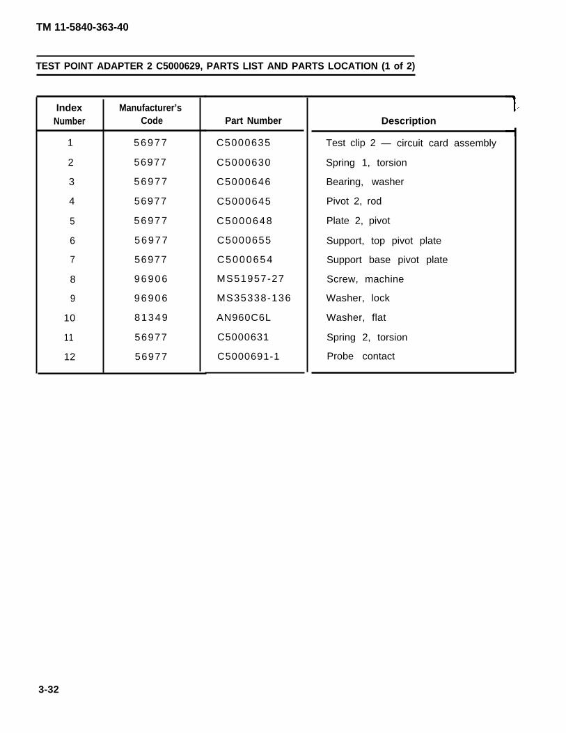
TM 11-5840-363-40
TEST POINT ADAPTER 2 C5000629, PARTS LIST AND PARTS LOCATION (1 of 2)
IndexNumber
1
2
3
4
5
6
7
8
9
10
11
12
Manufacturer’sCode
56977
56977
56977
56977
56977
56977
56977
96906
96906
81349
56977
56977
Part Number
C5000635
C5000630
C5000646
C5000645
C5000648
C5000655
C5000654
MS51957-27
MS35338-136
AN960C6L
C5000631
C5000691-1
Description
Test clip 2 — circuit card assembly
Spring 1, torsion
Bearing, washer
Pivot 2, rod
Plate 2, pivot
Support, top pivot plate
Support base pivot plate
Screw, machine
Washer, lock
Washer, flat
Spring 2, torsion
Probe contact
3-32

TM 11-5840-363-40
TEST POINT ADAPTER 2 C5000629, PARTS LIST AND PARTS LOCATION (2 of 2)
3-33/(3-34 blank)

TM 11-5840-363-40
Section VI. TEST POINT ADAPTER CABLE C5000649 MAINTENANCE
Page PageIntroduction . . . . . . . . . . . . . . . . . . . . . . . . . . . . . . . . . . . 3-35 Test Point Adapter Cable C5000649, Parts List andTest Point Adapter Cable C5000649, Schematic . . . 3-35 Parts Location . . . . . . . . . . . . . . . . . . . . . . . . . . . . . . . 3-36
This section contains the information required to maintain the test point adapter cable (partnumber C5000649). The following maintenance information is provided:
● Schematic● Parts list and parts location
TEST POINT ADAPTER CABLE C5000649, SCHEMATIC
See page FO-11 for the schematic of test point adapter cable (part number C5000649).
3-35
INTRODUCTION

TM 11-5840-363-40
TEST POINT ADAPTER CABLE C5000649, PARTS LIST AND PARTS LOCATION
IndexNumber
1
2
3
Manufacturer’sCode
81349
80063
81349
Part Number
M24308-4 -15
SM-A-800453-3
M24308-2 -4
Description
Plug connector
Identification marker
Receptacle connector
3-36

TM 11-5840-363-40
Section VIl. TEST POINT ADAPTER CABLE C5000651 MAINTENANCE
Page PagoIntroduction. . . . . . . . . . . . . . . . . . . . . . . . . . . . . . . . . . . . 3-37 Test Point Adapter Cable C5000651, Schematic . . . . 3-39Test Point Adapter Cable C5000651. Parts List and
Parts Location . . . . . . . . . . . . . . . . . . . . . . . . . . . . . . . 3-38
This section contains the information required to maintain the test point adapter cable (partnumber C5000651 ). The following maintenance information is provided:
● Parts list and parts location● Schematic
3-37
INTRODUCTION

TM 11-5840-363-40
TEST POINT ADAPTER CABLE C5000651, PARTS LIST AND PARTS LOCATI0N
Index Manufacturer’sNumber Code
1 81349
2 80063
3 56977
Part Number
M24308-4 -5
SM-A-800453-3
C5000697-1
Description
Plug connector
Identification marker
Adapter plug
3-38
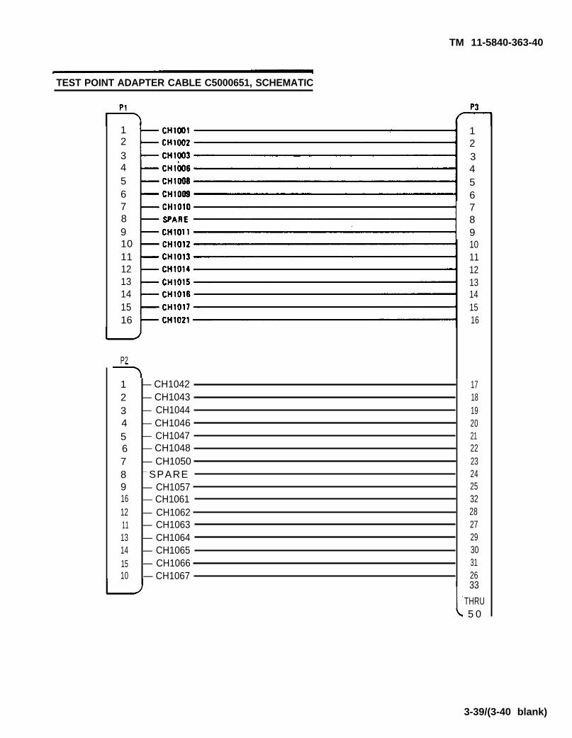
TM 11-5840-363-40
TEST POINT ADAPTER CABLE C5000651, SCHEMATIC
12345678910111213141516
P2
12345678916121113141510
— CH1042— CH1043— CH1044— CH1046— CH1047— CH1048— CH1050— SPARE— CH1057— CH1061— CH1062— CH1063— CH1064— CH1065— CH1066— CH1067
12345678910111213141516
17181920212223242532282729303126
3-39/(3-40 blank)
33
THRU5 0

TM 11-5840-363-40
Section VIII. TEST POINT ADAPTER CABLE C5OO0658 MAINTENANCE
Page PageIntroduction. . . . . . . . . . 3-41 Test Point Adapter Cable C5000658, Schematic 3-42
Test Point Adapter Cable C5000658, Parts List andParts Location . . . . . . . . . . . . . . . . . . . . . . 3-42
This section contains the information required to maintain the test point adapter cable (partnumber C5000658). The following maintenance information is provided:
Parts list and parts location Schemat i c
Change 1 3-41
I N T R O D U C T I O N

TM 11-5840-363-40
I TEST POINT ADAPTER CABLE C5000658, PARTS LIST AND PARTS LOCATION
Index Manufacturer’sNumber Code
1 96906
2 56977
3 56977
Part Number
MS3126F18-11P
C5000663-1
C5000663-2
Jack
TEST POINT ADAPTER CABLE C5000658, SCHEMATIC
Jack
3-42 Change 1
Description

TM 11-5840-363-40
CHAPTER 4
CARD TEST AND TROUBLESHOOTING
PageIntroduction ............................................... 4-1Card Test and Troubleshooting Index . . . . . . . . . . . 4-2Card Repair Parts Index . . . . . . . . . . . . . . . . 4-4Test Equipment and Accessories Index. . . . . . . . . 4-8Test Program Index . . . . . . . . . . . . . . . . . . . . 4-12
PageID Hookup . . . . . . . . . . . . . . . . . . . . . . . . . . . . . . . . . . . 4-18UUT Hookup . . . . . . . . . . . . . . . . . . . . . . . . . . . 4-20UUT and lD Removal . . . . . . . . . . . . . . . . . . . . . . . . . 4-24Explanation of Messages. . . . . . . . 4-26UUT Probing . . . . . . . . . . . . . . . 4-30
INTRODUCTION
This chapter contains the information you need to test and troubleshoot cards (UUTs) repairableat the general support level. There is one test and troubleshooting procedure for each card. Theprocedures are arranged in card part number order, so you can find them easily.
There are three indexes at the beginning of the chapter to help you. The first index (card test andtroubleshooting index) identifies the page number of each card test and troubleshootingprocedure. The second index (card repair parts index) helps you quickly find information requiredto order a new part. The third index (test equipment and accessories index) allows you to selectthe proper interconnection device, test point adapter, and test point adapter cable when testing acard. Procedures for hooking up these items are also contained in this chapter.
4-1

TM 11-5840-363-40
CARD TEST AND TROUBLESHOOTING INDEX (2 of2)
Card (UUT)Part Number
1635961-100
1635962-100
1635963-100
1635964-100
1635967-100
1635968-100
1635969-100
1635970-100
1635971-100
1635973-100
1635975-100
1635976-100
1635977-100
1635978-100
1635979-100
1635985-100
1635986-100
1635987-100
1635988-100
1635990-100
1642175-100
1642176-100
Page
4-152
4 - 1 5 4
4 -156
4 -158
4 -160
4 -162
4 - 1 6 4
4 -166
4 -168
4 - 1 7 0
4 -172
4 -174
4 -176
4 -178
4 -180
4 -182
4 -184
4 -186
4 -188
4 - 1 9 0
4 -192
4 -194
Card (UUT)Part Number
1642177-100
1642178-100
1642179-100
1642180-100
1642181-100
1642183-100
1642184-100
1642185-100
1642186-100
1642187-100
1642188-100
1642189-100
1642190-100
1650873-100
C5000511
SM-D-803125
SM-D-803128
SM-D-803137
SM-D-803140
SM-D-803146
SM-D-803152
SM-D-803161
Page
4-196
4 -198
4 -200
4 -202
4 -204
4 -208
4 - 2 1 0
4 -212
4 -214
4 -216
4 -218
4 -220
4 -222
4 -224
4 -226
4 -228
4 -230
4 -232
4 -234
4 -236
4 -238
4 -240
Change 1 4-2

CARD TEST AND TROUBLESHOOTING INDEX (2 of 2)
Card (UUT)Part Numher
,1635961-100
1635962-100
1635963-100
1635964-100
1635967-100
1635968-100
1635969-100
1635970-100
1635971-100
1635973-100
1635975-100
1635976-100
1635977-100
1635978-100
1635979-100
1635985-100
1635986-100
1635987-100
1635988-100
1635990-100
1642175-100
1642176-100
Page
4-152
4 -154
4 -156
4 -158
4 -160
4 -162
4 - 1 6 4
4 -166
4 -168
4 -170
4 - 1 7 2
4 -174
4 -176
4 -178
4 -180
4 -182
4 - 1 8 4
4 -186
4 -188
4 - 1 9 0
4 -192
4 -194
Card (UUT)Part Number
1642177-100
1642178-100
1642179-100
1642180-100
1642181-100
1642183-100
1642184-100
1642185-100
1642186-100
1642187-100
1642188-100
1642189-100
1642190-100
1650873-100
C5000511
SM-D-803125
SM-D-803128
SM-13-803137
SM-D-803140
SM-D-803146
SM-D-803152
SM-D-803161
Page
4-196
4 -198
4 -200
4 -202
4 -204
4 -208
4 -210
4 -212
4 -214
4 -216
4 -218
4 -220
4 -222
4 -224
4 -226
4 -228
4 -230
4 -232
4 -234
4 -236
4 -238
4 -240
Change 1 4-3
TM 11-5840-363-40

TM 11-5840-363-40
CARD REPAIR PARTS INDEX (1 of 4)
The index below allows you to determine the functional group code associated with the card youare testing. It also identifies the repair parts manual you should use to obtain repair parts for thecard. When you have isolated a problem to a faulty part, use the following procedure to find theinformation required to obtain a new part.
1. Identify card part number located on card.2. Use index below to determine the functional group code of card.3. Use index below to determine the repair parts manual you should use.4. Locate card parts list in repair parts manual.
a. Find functional group code of card in table of contents of repair parts manual,b. Turn to page specified by table of contents.
Card (UUT)
Part Number
4-4
1635841-100
1635842-100
1635843-100
1635845-1001635845-101
1635846-100
1635847-100
1635854-100
1635870-1001635870-101
1635871-100
1635872-100
1635882-100
1635883-100
1635884-100
1635885-100
1635886-100
1635910-100
1635911-100
1635912-100
1635913-100
1635914-100
1635915-100
1635916-100Change 1
FunctionalGroup Code
7TAB3AF01
7TAB3AF02
7TAB3AF03
7TAB3AF05
7TAB3AF06
7TAB3AF07
7TAB3AF04
7TBA6AL00
7TBA6AL60
7TBA6AL61
7SHA2
7SHA3
7SHA4
7SHA5
7SHD5
7SHA7
7SHC5
7SHC6
7SHC7
7SHC8
7SHC9
7SHD1
Repair PartsManual
TM11-584O-355-34P
TM11-5840-355 -34P
TM11-5840-355 -34P
TM11-5840-355 -34P
TM11-5840-355 -34P
TM11-5840-355 -34P
TM11-5840-355 -34P
TM11-5840-355 -34P
TM11-5840-355 -34P
TM11-5840-355 -34P
TM11-5840-364 -34P
TM11-5840-364 -34P
TM11-5840-364 -34P
TM11-5840-364 -34P
TM11-5840-364 -34P
TM11-5840-364 -34P
TM11-5840-364 -34P
TM11-5840-364 -34P
TM11-5840-364 -34P
TM11-5840-364 -34P
TM11-5840-364 -34P
TM11-5840-364-34P
o r
or

TM 11-5840-363-40
CARD REPAIR PARTS INDEX (2 of 4)
Card (UUT)
Part Number
1635917-100
1635918-100
1635919-100
1635920-100
1635921-100
1635922-100
1635923-100
1635924-100
1635925-100
1635926-100
1635927-100
1635928-100
1635929-100
1635930-100
1635931-100
1635932-100
1635933-100
1635935-100
1635936-100
1635937-100
1635939-100
1635940-100
1635941-100
1635942-100
1635944-1001635944-101
1635945-100
1635946-100
1635947-100
1635948-100
1635949-100
1635950-100
FunctionalGroup Code
7SHD3
7SHD6
7SHD7
7SHD9
7SHE2
7SHE3
7SHE4
7SHE5
7SHE6
7SHE7
7TAB2AP19B
7SHE8
7SHE9
7SHF1
7SHF2
7SHF5
7SHF6
7SHF7
7SHF8
7SHM3
7SHG6
7SHH1
7SHH7
7SHH8
7SHI3
7SHI4
7SHI5
7SHJ4
7SHJ5
7SHJ6
7SHJ7
Repair PartsManual
TM11-5840-364 -34P
TM11-5840-364 -34P
TM11-5840-364 -34P
TM11-5840-364 -34P
TM11-5840-364 -34P
TM11-5840-364 -34P
TM11-5840-364 -34P
TM11-5840-364 -34P
TM11-5840-364 -34P
TM11-5840-364 -34P
TM11-5840-355 -34P
TM11-5840-364 -34P
TM11-5840-364 -34P
TM11-5840-364 -34P
TM11-5840-364 -34P
TM11-5840-364 -34P
TM11-5840-364 -34P
TM11-5840-364 -34P
TM11-5840-364 -34P
TM11-5840-364 -34P
TM11-5840-364 -34P
TM11-5840-364 -34P
TM11-5840-364 -34P
TM11-5840-364 -34P
TM11-5840-364 -34P
TM11-5840-364 -34P
TM11-5840-364 -34P
TM11-5840-364 -34P
TM11-5840-364 -34P
TM11-5840-364 -34P
TM11-5840-364 -34PChange 1 4-5
or

TM 11-5840-363-40
CARD REPAIR PARTS INDEX (3 of 4)
Card (UUT)
Part Number
1635951-100
1635952-100
1635953-100
1635954-100
1635955-100
1635956-100
1635957-100
1635960-100
1635961-100
1635962-100
1635963-100
1635964-100
1635967-100
1635968-100
1635969-100
1635970-100
1635971-100
1635973-100
1635975-100
1635976-100
1635977-100
1635978-100
1635979-100
1635985-100
1635986-100
1635987-100
1635988-100
1635990-100
1642175-100
1642176-100
F u n c t i o n a lGroup Code
7SHJ8
7SHJ9
7SHK1
7SHK2
7SHK3
7SHK4
7SHK5
7SHK6
7SHK7
7SHK8
7SHK9
7SHL1
7SHL2
7SHL3
7SHL4
7SHL5
7SHL6
7SHM1
7SHM2
7 T B A 6 A L 6 2
7SHM6
7SHN1
7SHM8
7TAB2AP19F
7TBA6AL63
7TBA6AL65
7TAB2AP19H
7TAB2AP19I
7SHN2
7SHN3
Repair PartsManual
TM11-5840-364 -34P
TM11-5840-364 -34P
TM11-5840-364 -34P
TM11-5840-364 -34P
TM11-5840-364 -34P
TM11-5840-364 -34P
TM11-5840-364 -34P
TM11-5840-364 -34P
TM11-5840-364 -34P
TM11-5840-364 -34P
TM11-5840-364 -34P
TM11-5840-364 -34P
TM11-5840-364 -34P
TM11-5840-364 -34P
TM11-5840-364 -34P
TM11-5840-364 -34P
TM11-5840-364 -34P
TM11-5840-364 -34P
TM11-5840-364 -34P
TM11-5840-364 -34P
TM11-5840-364 -34P
TM11-5840-364 -34P
TM11-5840-364 -34P
TM11-5840-355 -34P
TM11-5840-355 -34P
TM11-5840-355 -34P
TM11-5840-355 -34P
TM11-5840-355 -34P
TM11-5840-364 -34P
TM11-5840-364 -34P
4-6

TM 11-5840-363-40
CARD REPAIR PARTS INDEX (4 of 4)
Card (UUT)
Functional Repair PartsPart Number Group Code Manual
1642177-100 7SHN4 TM11-5840-364 -34P
1642178-100 7SHN5 TM11-5840-364 -34P
1642179-100 7SHN6 TM11-5840-364 -34P
1642180-100 7SHN7 TM11-5840-364 -34P
1642181-100 7SHN8 TM11-5840-364 -34P
1642182-100 7SHN9 TM11-5840-364 -34P
1642183-100 7SHP4 TM11-5840-364 -34P
1642184-100 7SHO9 TM11-5840-364 -34P
1642185-100 7SHP1 TM11-5840-364 -34P
1642186-100 7SHP2 TM11-5840-364 -34P
1642187-100 7SHP3 TM11-5840-364 -34P
1642188-100 7SHP5 TM11-5840-364 -34P
1642189-100 7SHP6 TM11-5840-364 -34P
1642190-100 7SHP9 TM11-5840-364 -34P
1650873-100 7SHQ4 TM11-5840-364 -34P
C5000511 6TGC2AD08 TM11-5840-354 -34P
SM-D-803125 6TGC2AD02 TM11-5840-354 -34P
SM-D-803128 6TGC2AD03 TM11-5840-354 -34P
SM-D-803137 6TGC2AD04 TM11-5840-354 -34P
SM-D-803140 6TGC2AD05 TM11-5840-354 -34P
SM-D-803146 6TGC2AD06 TM11-5840-354 -34P
SM-D-803152 6TGC2AD09 TM11-5840-354 -34P
SM-D-803161 6TGC2AD25 TM11-5840-354 -34P
4-7

TM11-5840-363-40
TEST EQUIPMENT AND ACCESSORIES INDEX (1 of 4)
Use the index below to select the proper ID, test point adapter, test point adapter cable, and DIPsocket plug (with attached cable) for the card (UUT) you are testing. When a card does not require
an item (test point adapter, DIP socket plug, etc), this will be indicated by . . . in the appropriate column.
Card (UUT)
1635841-100
1635842-100
1635843-100
1635845-100
1635845-101
1635846-100
1635847-100
1635854-100
1635870-100
1635871-100
1635872-100
1635882-100
1635883-100
1635884-100
1635885-100
1635886-100
1635910-100
1635911-100
1635912-100
1635913-100
1635914-100
1635915-100
1635916-100
1635917-100
1635918-100
1635919-100
ID
C5000621
C5000621
C5000621
C5000621
C5000621
C5000621
C5000621
C5000621
C5000621
C5000610
C5000610
C5000610
C5000610
C5000610
C5000610
C5000610
C5000610
C5000610
C5000610
C5000610
C5000610
C5000610
C5000610
C5000610
C5000610
C5000610
Test PointAdapter/
Power CableAssembly
C5000628
C5000628
C5000628
C5000628
C5000628
C5000628
C5000628
C5000628
C5000628
C5000628
C5000628
C5000628
C5000628
C5000628
C5000628
C5000628
C5000628
C5000628
C5000628
C5000628
C5000628
C5000628
C5000628
C5000628
Part Number
Test PointAdapter Cable
C5000649
C5000649
C5000649
...
...
C5000649
C5000649
C5000649
C5000649
C5000649
C5000649
C5000649
C5000649
C5000649
C5000649
C5000649
C5000649
C5000649
C5000649
C5000649
C5000649
C5000649
C5000649
C5000649
C5000649
C5000649
DIP
Part Number
. . .
. . .
. . .
. . .
. . .
. . .
. . .
..
. . .
. . .
. . .
C5000651
. . .
. . .
. . .
. .
C5000651
,.
,..
. . .
. .
C5000651
Socket PlugDestination
PlugIdent
. . .
. .
. . .
.
.
.
.
.
. . .
. .
.,.
. .
. .
. . .
. .
.
.,.
Card DIPSocket
.,.
. . .
. . .
. . .
. . .
. . .
.,.
. . .
. . .
. . .
. .
. . .
. . .
TPS38
.
. . .
.
. . .
. . .
TPS44
,..
. .
TPS48
Notes
4-8 Change 1

TM 11-5840-363-40
TEST EQUIPMENT AND ACCESSORIES INDEX (2 of 4)
Card (UUT)
1635920-100
1635921-100
1635922-100
1635923-100
1635924-100
1635925-100
1635926-100
1635927-100
1635928-100
1635929-100
1635930-100
1635931-100
1635932-100
1635933-100
1635935-100
1635936-100
1635937-100
1635939-100
1635940-100
1635941-100
1635942-100
1635944-100
1635944-101
1635945-100
1635946-100
1635947-100
1635948-100
1635949-100
1635950-100
ID
C5000610
C5000610
C5000610
C50000610
C5000610
C5000610
C5000610
C5000610
C5000610
C5000610
C5000610
C5000610
C5000610
C5000610
C5000610
C5000610
C5000610
C5000610
C5000610
C5000610
C5000610
C5000621
C5000621
C5000610
C5000610
C5000610
C5000610
C5000610
C5000610
Part Number
Test PointAdapter/
Power CableAssembly
C5000628
C5000628
. . .
C5000628
C5000628
C5000628
C5000628
C5000628
C5000628
C5000628
C5000628
C5000628
C5000628
C5000628
C5000628
C5000628
C5000628
C5000628
C5000628
C5000628
. . .
. . .
. . .
C5000628
C5000628
C5000628
C5000628
C5000628
C5000628
Test PointAdapter Cable
C5000649
C5000649
. . .
C5000649
C5000649
C5000649
C5000649
C5000649
C5000649
C5000649
C5000649
C5000649
C5000649
C5000649
C5000649
C5000649
C5000649
C5000649
C5000649
C5000649
. . .
. . .
. . .
C5000649
C5000649
C5000649
C5000649
C5000649
C5000649
DIP Socket Plug
Part Number
. . .
. . .
. . .
. . .
. . .
. . .
. . .
. . .
. . .
. . .
. . .
. . .
. . .
C5000651
. . .
. . .
. . .
. . .
. . .
. . .
. . .
,..
. . .
. . .
. . .
C5000651C5000651
.
C5000651C5000651
. . .
Destination
. . .
. . .
. . .
. . .
. . .
. . .
. . .
. . .
. . .
. . .
. . .
. . .
P1
. . .
. . .
.
,..
. . .
. . .
. . .
. . .
. . .
. . .
. . .
P1P2
. . .
P2P1
. .
Card DIPSocket
. . .
. . .
. . .
. . .
. . .
. . .
. . .
. . .
. . .
. . .
. . .
. . .
TPS24
. . .
. . .
. . .
. . .
. . .
. . .
. . .
. . .
. . .
. . .
. . .
TPS24TPS37
. . .
TPS34TPS39
...
Notes
Change 1 4-9
PlugIdent
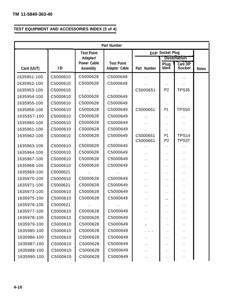
TM 11-5840-363-40
TEST EQUIPMENT AND ACCESSORIES INDEX (3 of 4)
Card (UUT)
1635951-100
1635952-100
1635953-100
1635954-100
1635955-100
1635956-100
1635957-100
1635960-100
1635961-100
1635962-100
1635963-100
1635964-100
1635967-100
1635968-100
1635969-100
1635970-100
1635971-100
1635973-100
1635975-100
1635976-100
1635977-100
1635978-100
1635979-100
1635985-100
1635986-100
1635987-100
1635988-100
1635990-100
C5000610
C5000610
C5000610
C5000610
C5000610
C5000610
C5000610
C5000610
C5000610
C5000610
C5000610
C5000610
C5000610
C5000610
C5000621
C5000610
C5000621
C5000610
C5000610
C5000621
C5000610
C5000610
C5000610
C5000610
C5000610
C5000610
C5000610
C5000610
Part Number
Test PointAdapter/
Power CableAssembly
C5000628
C5000628
. . .
C5000628
C5000628
C5000628
C5000628
C5000628
C5000628
C5000628
C5000628
C5000628
C5000628
C5000628
. . .
C5000628
C5000628
C5000628
C5000628
. . .
C5000628
C5000628
C5000628
C5000628
C5000628
C5000628
C5000628
C5000628
Test PointAdapter Cable
C5000649
C5000649
. . .
C5000649
C5000649
C5000649
C5000649
C5000649
C5000649
C5000649
C5000649
C5000649
C5000649
C5000649
. . .
C5000649
C5000649
C5000649
C5000649
. . .
C5000649
C5000649
C5000649
C5000649
C5000649
C5000649
C5000649
C5000649
DIP
Part Number
. . .
. . .
C5000651
. . .
C5000651
. . .
. . .
. . .
C5000651C5000651
. . .
. . .
. . .
. . .
. . .
. . .
. . .
. . .
. . .
. . .
. . .
. . .
,..
. . .
. . .
. . .
. . .
. . .
. . .
. . .
P2
. . .
P1
. . .
. . .
. . .
P1P2
. . .
. . .
. . .
. . .
. . .
. . .
. . .
. . .
,.,
. . .
. . .
. . .
. . .
. . .
. . .
. . .
. . .
. . .
. . .
. . .
TPS35
. . .
TPS50
. . .
. . .
. . .
TPS14TPS37
. . .
. . .
. . .
. . .
. . .
. . .
. . .
. . .
. . .
. . .
. . .
. . .
. . .
. . .
. . .
. . .
. . .
. . .
Notes
4-10
Socket PlugDestination
PlugIdent
Card DIPSocketI D

TM 11-5840-363-40
TEST EQUIPMENT AND ACCESSORIES INDEX (4 of 4)
Card (UUT)
1642175-100
1642176-100
1642177-100
1642178-100
1642179-100
1642180-100
1642181-100
1642183-100
1642184-100
1642185-100
1642186-100
1642187-100
1642188-100
1642189-100
1642190-100
1650873-100
C5000511
SM-D-803125
SM-D-803128
SM-D-803137
SM-D-803140
SM-D-803146
SM-D-803152
SM-D-803161
C5000621
C5000621
C5000621
C5000621
C5000621
C5000621
C5000621
C5000621
C5000621
C5000621
C5000621
C5000621
C5000621
C5000621
C5000621
C5000621
C5000610
C5000610
C5000610
C5000610
C5000610
C5000610
C5000610
C5000610
Test PointAdapter/
Power CableAssembly
C5000628/C5000658
C5000628
C5000628
C5000628/C5000658
C5000628/C5000658
C5000628/C5000658
C5000628
C5000628
C5000628
C5000628/
C5000658
C5000628
C5000628
C5000628
C5000628
C5000628
C5000628
C5000629
C5000629
C5000629
C5000629
C5000629
C5000629
C5000629
. . .
Part Number
Test PointAdapter Cable
C5000649
C5000649
C5000649
C5000649
C5000649
C5000649
C5000649
C5000649
C5000649
C5000649
C5000649
C5000649
C5000649
C5000649
C5000649
C5000649
C5000649
C5000649
C5000649
C5000649
C5000649
C5000649
C5000649
. . .
Part Number
. . .
. . .
. . .
.,.
. . .
. . .
. . .
...
. . .
. . .
. . .
. . .
. . .
. . .
. . .
. . .
. . .
. . .
. . .
. . .
C5000651
. . .
. . .
. . .
. . .
. . .
. . .
. . .
. . .
. . .
. . .
. . .
. . .
. . .
. . .
. . .
. . .
. . .
. . .
. . .
. . .
. . .
. . .
. . .
P1
. . .
. . .
. . .
Card DIPSocket
. . .
. . .
. . .
. . .
. . .
. . .
. . .
. . .
. . .
. . .
. . .
. . .
. . .
. . .
. . .
. . .
. . .
. . .
. . .
. . .
TPS45
. . .
. . .
. . .
Notes
● Card (UUT) must be tested using TEST CLIP 3781-12(05276) (NSN 6625-00-242-9945)
Change 1 4-11
IDPlugIdent
DIP Socket Plug
Destination

TEST PROGRAM INDEX
For complete listing of test program file names including latest revision numbers, refer to thecurrent issue of the US Army Communications-Electronics Command Test program Set (TPS)Index.
4-12 Change 1
TM 11-5840-363-40

TM 11-5840-363-40
THIS PAGE INTENTIONALLY LEFT BLANK
Change 1 4-13 THRU 4-17 DELETED)

TM 11-5840-363-40
ID HOOKUP (1 of 2)
The ID mating connector J1 (7) on the AN/USM-410V) programmable interface unit (PIU) (1) is avery delicate connector. Use great care when inserting or removing ID (4) from this connector.
Use table on page 4-8 to select ID and obtain selected ID from storage.Examine J1 (7) on PIU and P1 (6) on ID for foreign matter. Clean these connectors as required.
Be certain that J1 on PIU and P1 on ID are both free of foreign matterbefore mating the ID with the PIU. Use great care when mating P1 on IDwith J1 on PIU to avoid damage to the connectors.
Hold ID (4) by handles (5) and carefully slide ID over guide pins (3) and into connector J1 onPIU. Ensure that ID is positioned straight on J1 of PIU.When ID has been fully inserted, rotate black bar handle (2) 90 degrees so that handle pointsoutward.When ID hookup is complete, press PROCEED key at terminal.a. If correct ID has been selected and ID hookup is correct, crt displays the following:
OPERATOR ACTIONPERFORM UUT HOOKUP AS ILLUSTRATED
SEE TM 11-5840-363-40PRESS PROCEED WHEN COMPLETED
b. If incorrect ID has been hooked up or if hookup is faulty, a failure message appears on thecrt along with additional instructions.
4-18 Change 1
1 .2 .
3.
4.
5.

4-19
ID HOOKUP (2 of 2)
TM 11-5840-363-40

TM 11-5840-363-40
UUT HOOKUP (1 of 4)
The UUT is installed in the ID with the ID removed from the PIU. The ID is laid backside down on afirm surface for inserting the UUT. After the UUT is inserted, the ID is reinstalled on the PIU. Afterthe ID is reinstalled, the test point adapter and cable and the DIP socket plug(s) and cable areinstalled if required. Great care should be exercised when installing the UUT in the ID or wheninstalling or removing the ID from the PIU. The connectors are delicate and are easily damaged ifcare is not used. Damaged connectors on the ID mayfailures.
1. Use table on page 4-8 to select test point adapter,plug as required.
cause UUT “failures” that - are not real
test point adapter cable, and DIP socket
Use great care when removing ID from PIU to prevent damage to theconnectors.
2. Remove ID (4) from PIU (1).a. Release ID by rotating black bar handIe (2) 90 degrees so that handle is parallel to PIU
cabinet.b. Hold ID by handles (23) and carefully pull ID straight out to disconnect it from J1 (24) on
PIU.3. Place ID backside down on a firm flat surface.4. Inspect connector on UUT (7) for bent pins. Straighten any pins that are bent before
attempting to install UUT in ID.
Use great care when inserting UUT into ID card connector to prevent damage to theconnector. Do not attempt to install UUT if any UUT connector pins are bent. Duringtesting, many UUT “faults” will be detected on a good UUT if ID connectors or pinsare damaged.
5. Carefully install UUT in ID.a. UUTs with 100-pin connectors are inserted in the ID left-hand card connector with the
UUT components to the left.b. UUTs with 80-pin connectors are inserted in the ID right-hand card connector with the
components to the right.c. Slide- UUT into guide (19) until UUT connector P1 (7) contacts ID connector (22).d. Press firmly on top edge of UUT until UUT seats in ID connector (22).
6. Examine J1 (24) on PIU and P1 on ID for foreign matter. Clean these connectors as required.
Be certain that J1 on PIU and P1 on ID are both free of foreign matterbefore mating the ID with the PIU. Use great care when mating P1 on IDwith J1 on PM to avoid damage to the connectors.
7. Install ID on PIU.a. Hold ID by handles (23) and carefully slide ID over guide pins (3) and into connector J1 (24)
on PIU. Make certain that ID is positioned straight on J1 of PIU.b. When ID has been fully inserted, rotate black bar handle (2) 90 degrees so that it faces
outward.
4-20 Change 1
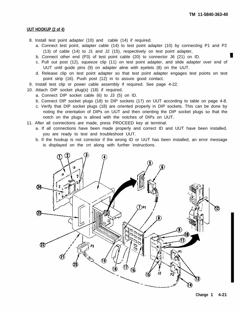
TM 11-5840-363-40
8. Install test point adapter (10) and cable (14) if required.a. Connect test point, adapter cable (14) to test point adapter (10) by connecting P1 and P2
(13) of cable (14) to J1 and J2 (15), respectively on test point adapter,b. Connect other end (P3) of test point cable (20) to connector J6 (21) on ID.c. Pull out post (12), squeeze clip (11) on test point adapter, and slide adapter over end of
UUT until guide pins (9) on adapter aline with eyelets (8) on the UUT.d. Release clip on test point adapter so that test point adapter engages test points on test
point strip (16). Push post (12) in to assure good contact.9. Install test clip or power cable assembly if required. See page 4-22.
10. Attach DIP socket plug(s) (18) if required.a. Connect DIP socket cable (6) to J3 (5) on ID.b. Connect DlP socket plugs (18) to DIP sockets (17) on UUT according to table on page 4-8.c. Verify that DIP socket plugs (18) are oriented properly in DIP sockets. This can be done by
noting the orientation of DIPs on UUT and then orienting the DIP socket plugs so that thenotch on the plugs is alined with the notches of DIPs on UUT.
11. After all connections are made, press PROCEED key at terminal.a. If all connections have been made properly and correct ID and UUT have been installed,
you are ready to test and troubleshoot UUT.b. If the hookup is not corrector if the wrong ID or UUT has been installed, an error message
is displayed on the crt along with further instructions.
Change 1 4-21
UUT HOOKUP (2 of 4)

TM 11-5840-363-40
Some cards require attaching a test clip or power cable assembly during test. Consult thefollowing table to select appropriate part. Do not connect test clip until instructed to do so in therespective procedure.
Card Number Part Number Procedure
1635871-100 3781-12 (05276) 1. Attach Test Clip from P1 Pin 28 to U41 P12. On Test Point Adapter (C5000629) attach Test Clip
from TP18 to TP14.
1635945-100 3781-12 (05276) 1. Attach Test Clip from P1 Pin 7 to U19 Pin 112. Attach Test Clip from P1 Pin 7 to U35 Pin 83. Remove Test Clip
1635954-100 3781-12 (05276) Attach Test Clip from U11 Pin 3 to U22 Pin 5
1642178-100 C5000658 Attach Power Cable Assembly from DIU J36/P1 to P2/lDTP1 (red) and P3/lD TP2 (black)
1642179-100 C5000658 Attach Power Cable Assembly from DIU J36/P1 to P2/lDTP1 (red) and P3/lD TP2 (black)
1642180-100 C5000658 Attach Power Cable Assembly from DIU J36/P1 to P2/lDTP1 (red) and P3/lD TP2 (black)
1642185-100 C5000658 Attach Power Cable Assembly from DIU J36/P1 to P2/lDTP1 (red) and P3/lD TP2 (black)
1642190-100 3781-12 (05276) Attach Test Clip from U8 Pin 7 to TP3
4-22 Change 1
UUT HOOKUP (3 of 4)
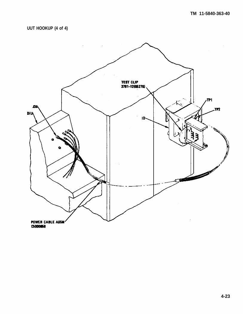
TM 11-5840-363-40
4-23
UUT HOOKUP (4 of 4)

TM 11-5840-363-40
UUT AND ID REMOVAL (1 of 2)
The UUT is removed from the ID after the ID is removed from the PIU. First the DIP plugs and thetest point adapter cable are removed from the UUT and the ID. The ID is then removed from thePIU with the UUT still installed. The ID is placed backside down on a firm flat surface. The testpoint adapter is removed from the UUT; then the UUT is removed from the ID. Great care shouldbe exercised when removing the ID from the PIU to prevent damage to connector J1 on the PIU.
1.2.3.
4.5.
6.7.8.
9.
10.11.
12.13.
If used, remove DIP plugs (12) from DIP sockets (11) on UUT.Remove DIP plug cable connector (5) from ID connector (4).If used, remove test point adapter connectors (9) from test point adapter (10) by pullingstraight out.Remove test point adapter cable plug (14) from J6 (15) on ID (3).Release ID (3) by rotating black bar handle (2) 90 degrees so that handle is parallel to the frontof the PIU.
Use great care when removing P1 on ID from J1 on PIU to prevent damageto the connectors.
Hold ID by handles (18) and carefully pull ID straight out from J1 (17) on PIU (1).Lay ID with backside down on a firm flat surface.Pull post (8) out, squeeze clip (7) on test point adapter (10), and disconnect test point adapterfrom UUT by moving adapter to the right to disengage test point connectors and guide pins.While
Insert
still squeezing clip (7), remove test point adapter from UUT.
When removing UUT from ID, do not grasp UUT by any of the components. Use cardextractor when removing UUT from ID. The card extractor tool is used to unseat theUUT only. When the UUT is unseated, remove the extractor from the UUT and removethe UUT from the ID by hand to avoid dropping the UUT.
2 pins (22) of card extractor into 2 holes (23) in UUT (24).Rest ends of card extractor (18,21) on ID card brackets (13), and push firmly on extractorhandle (20) until UUT unseats.Remove card extractor from UUT (24), and pull UUT out of ID by hand.Return ID, test point adapter, test point adapter cable, and DIP plugs to their proper storage.
4-24 Change 1
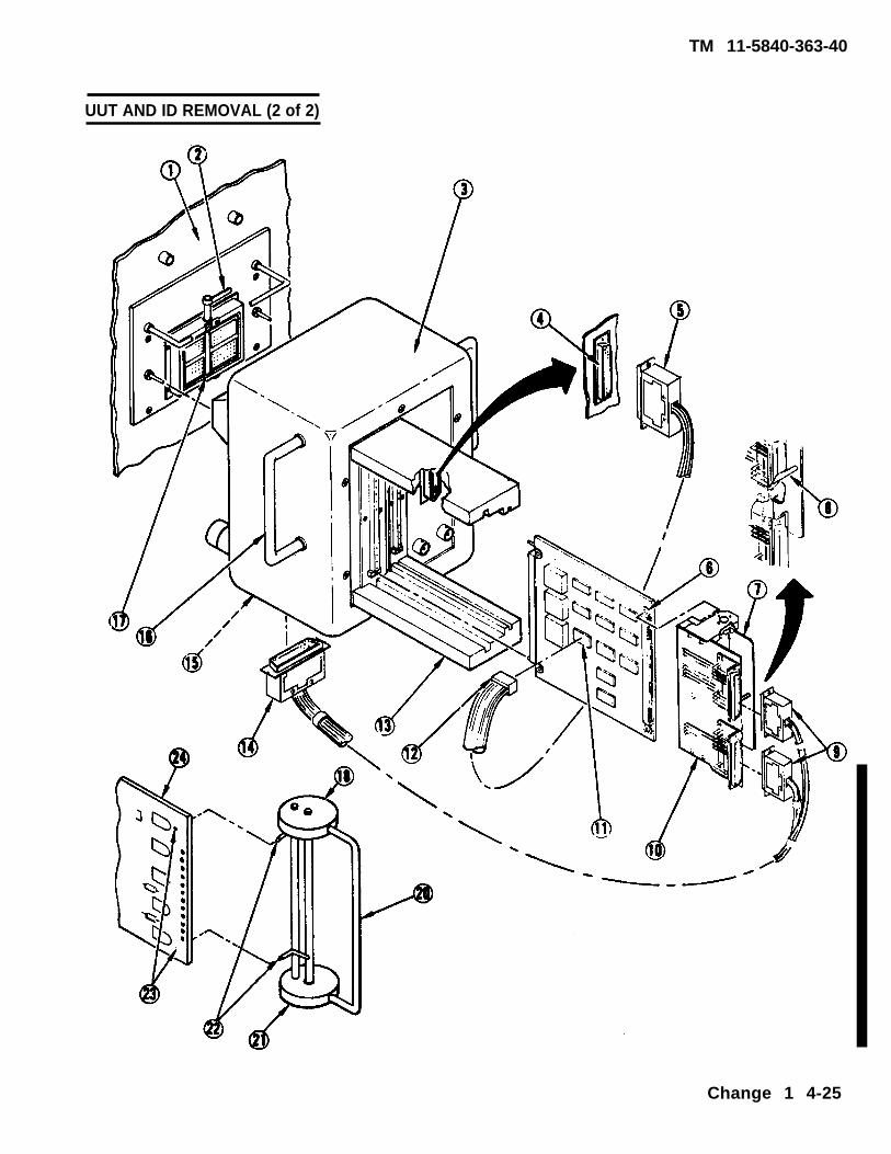
UUT AND ID REMOVAL (2 of 2)
Change 1 4-25
TM 11-5840-363-40

TM 11-5840-363-40
EXPLANATION OF MESSAGES (1 of 4)
During execution of a card test program, messages will be printed at the line printer and/ordisplayed on the crt. There are three types of messages used:
● Operator action messages● End of program messages● Fault or replacement messages.
Some of these messages will require action by the operator to correct a problem. The operatoractions for each messsage type are given in the following paragraphs.
OPERATOR-ACTION MESSAGES
Operator action messages give instructions, to the operator for the following actions:
● To perform lD hookup (page 4-18)● To perform UUT hookup (page 4-20)● To perform PIU probe hookup (page 4-30)● To enter part number and manufacturing sequence number (see appropriate card test
procedure)● To remove ID (page 4-24)● To probe UUT (page 4-30)
For information on how to perform the procedures listed above, see the page number given witheach action.
4-26

TM 11-5840-363-40
EXPLANATION OF MESSAGES (2 of 4)
END OF PROGRAM MESSAGES
End of program messages occur when the test program is terminated. The reason for the programtermination is printed underneath the end of program message. By using the reason and thefollowing table, the next steps for the operator to follow can be determined.
Reason for Termination Message Operator Action
INCORRECT UUT P/N 1. Check out part number and see if correct part number wasentered.
2. Verify that correct test for UUT has been selected.
THIS PROGRAM DOES NOT 1. Check UUT MSN and see if correct MSN number wasTEST MSN XXX entered.
2. Verify that correct test for UUT has been selected.
UUT FAILED 1. Visually inspect UUT for shorts between power and ground,STTO TEST FAILED and power and power, If short exists, repair UUT and then
test UUT.2. If no shorts exist, tag and send UUT to depot for repair.
UUT FAILED Tag and send UUT for repair by replacement of parts asindicated by replacement or fault set message.
UUT PASSED ALL TESTS No further operator action required,
ID SIGNATURE TEST FAILED Check ID part number and verify that the ID part number is thecorrect one for the UUT as given in the table on pages 4-8through 4-11,
ID C5000XXX FAILED 1. Remove ID from PIU and reinstall, then rerun the test.2. If the same termination message appears, send ID for repair.
SYSTEM FAULTY Run system self test.RUN SELF TEST
UUT HAS ONLY FAULTS THAT 1. Remove ID from PIU. Disconnect test point adapter, cable,DO NOT APPEAR IN THE FAULT and DIP socket plug cable (if not required for testing) andDICTIONARY remove UUT from. ID. Rerun the test.
2. If the same termination message appears, send UUT to depot.
4-27

TM 11-5840-363-40
EXPLANATION OF MESSAGES (3 of 4)
When a fault has been detected during execution of a UUT test program, one of three fault orreplacement messages will be printed.
● Safe-to-turn-on test failure message● Replacement message● Fault set message
The safe-to-turn-on test is performed on the UUT before power is applied to the UUT. If a safe-to-turn-on fault is detected, visually inspect the UUT for shorts between power and ground, andpower and power. If a short is found, repair UUT and send for retest. If no visual indication of ashort is found, send the UUT to the depot.
When a fault is detected on a UUT, either a list of parts to be replaced will be printed after the endof program message or a list of probable fault sets is printed before the end of program message.If a list of replacement parts is printed, replace all parts on the list and then run the UUT test again.If UUT still fails test and no new replacement parts are listed, send UUT back to depot. If new partis listed, replace new part and run test again. Repeat this procedure until the UUT passes test orUUT must be sent to depot.
On some UUTs, a list of fault sets is printed as shown below. A fault set is a list of the mostprobable causes of failure detected by the UUT test.
THE MOST PROBABLE FAULT SETS ARE LISTED IN ORDER OF PRECEDENCE.
FAULTY ALTERNATE FAILURE FAILURE DEGREE OFRANK UNIT UNITS DESCRIPTION SET NO. MISMATCH
1 U48 U33 U48P11 (SAO) 236 0U42
. . . . . . . . . . . . . . . . . . . . . . . . . . . . . . . . . . . . . . . . . . . . . . . . . . . . . . . . . . . . . . . . . . . . . . . . . . . . . . . . . . . . . . . . . . . . . . . . . . . . . . . . . . . . . . . . . . .
2 U39 8 8 8 8 *U39-15 214 5. . . . . . . . . . . . . . . . . . . . . . . . . . . . . . . . . . . . . . . . . . . . . . . . . . . . . . . . . . . . . . . . . ... . . . . . . . . . . . . . . . . .
3 U40 U39 U40P8 (SAO) 258 5U23 U4P12 *U23-28U23 GND *U23-27U23 GND *U23-26U23 GND *U23-14U23 U40 U23P5 (SAO)
4 U39 W 5 U39P12 (SAO) 213 15W 5 TP121 W 5 (SAO)
U38U48
INPUT W 5 TP21 (SAO). . . . . . . . . . . . . . . . . . . . . . . . . . . . . . . . . . . . . . . . . . . . . . . . . . . . . . . . . . . . . . . . . . . . . . . . . . . . . . . . . . . . . . . . . . . . . . . . . . . . . . . . . . . . . . . . . . . .
4-28
FAULT AND REPLACEMENT MESSAGES
TM 11-5840-363-40
EXPLANATION OF MESSAGES (4 of 4)
FAULT AND REPLACEMENT MESSAGES
The fault sets are ranked according to the degree of mismatch, with the fault set with the lowestdegree of mismatch ranked number 1. The degree of mismatch indicates how accurately the faultisolation was performed. When the fault sets are Iisted, all parts under FAULTY UNIT column in thefirst fault set must be replaced and the test rerun, If the same fault sets are listed again, replace allparts under ALTERNATE UNITS in first fault set if any exist; otherwise, replace parts listed in nextfault set FAULTY UNIT column. Continue this procedure until the UUT is repaired or the list of faultsets is exhausted, in which case, the UUT must be sent to depot for repair.
As an example, in the list of fault sets shown above, U48 under the FAULTY UNIT column in the firstfault set would be replaced first and the test rerun. If the same fault sets were listed again, bothU33 and U42 under the ALTERNATE UNITS column would be replaced, and so on. When replacingparts, entries in the FAULTY UNIT or ALTERNATE UNITS column such as 88, W5, TP121 and INPUT,as shown in the above list of fault sets, should be ignored because they are not replaceable parts.
4-29

TM 11-5840-363-40
UUT PROBING (1 of 2)
Some UUT test procedures will require probing of parts on the UUT. With a probe connected toone of the jacks on the PIU or ID, you are instructed to connect the probe by one of the followingmessages:
***** OPERATOR ACTION *****CONNECT PIU PROBE TO XXXXXFOR FAULT ISOLATION PROBING
>> PRESS PROCEED WHEN READY <<
Connect probe (5) to either PIU-J2 (1), PIU-J3 (2), ID-J4 (4), ID-J5 (3) as indicated by XXXXX inthe operator action message. Press PROCEED when probe has been connected.
If probing is required after you press PROCEED, one of the following types of messages will beprinted. The first type of message has the following form:
CONNECT PROBE FROM JX TO NODE YY
Where X is the jack number that probe is connected to and YY is the node number. To find nodenumber YY, look up the appropriate card test procedure and use the part location diagram to findthe node YY. The second type of message is as follows:
PRESS YES FOR PROBING INSTRUCTIONSNO TO BYPASS PROBING
This message allows you to choose whether you want to probe to isolate the faulty unit in the firstfault set or to have the most probable fault sets listed. The last type of message has the followingform. Normally, you will want to probe to fault isolate the faulty unit within the first fault. Ifreplacing the faulty units and alternate units in the first fault set does not fix the UUT and the samefault set is listed, you must answer no to this prompt and then replace the parts in the next faultset.
When you answer yes to this prompt the following message will be displayed:
SET PROBE ON UUT POINT XXX
Where XXX has the form and meaning shown in the table below.
Probe Message Form Probe Point
XX or XX INPUT Input pin number XX of UUT connector P 1UXXPYY Pin YY of integrated circuit UXX
TPX Test point X on test point adapter or UUT test point strip
WXX or Look in table on appropriate card test procedure to determine probe pointVCC or The entry in the table will contain a probe point of one of the above formsGND or or a number. If a number is listed, use parts location diagram to locate
UXXZYY or probe point.RXPY
4-30

TM 11-5840-363-40
UUT PROBING (2 of 2)
When probing UUTs, the following rules should be observed:
● If clip type tip of probe is used, scrape conformal coating off part lead and make goodcontact between probe and part lead.
● If needle point of probe is used, use needle point to penetrate conformal coating.● Verify that the probe is connected to the proper ID or PIU jack and the correct node
point before pressing PROCEED.● Rerun test if probe slips off node point.● Do not remove probe from node until instructed by the crt.
4-31

1635841-100 TIMING AND RESET CARD TEST AND TROUBLESHOOTING (1 of 2)
1. Turn on AN/USM-410(V) tester.a. Perform AN/USM-410(V) tester startup per TM 11-6625-2773-12-1.b. Verify R is displayed on crt. If R is not displayed, turn tester off and restart per TM
11-6625-2773-12-1.c. Type DIR BACKGROUND at terminal and press RETURN key.d. Observe R is displayed on crt.e. At TEST OPERATORS PANEL, select ALL TESTS, VIDEO DISPLAY, and PRINTER.
2. Select test.a. Type TEST 1635841TXX at terminal and press RETURN key. See test program index (page
4-12) for current revision number (the Iast two digits of the file name).b. Observe the following message on crt. Verify UUT number on top line is correct; disregard
remainder of message. If UUT number is not correct, press and hold COMMAND key andpress HALT key. Release both keys and type in correct test number per step 2a.
TEST-STEP#: LINE#: EQUATE XXUUT: 1635841TXX. IC XX/XX/XX
MEAS VALUE:. . . . . . . . . . . . . . . . . . . . . . . . . . . . . . . . . . . . . . .- RUN TIME SYSTEM REV X.XX ----------------------------------------
**PIU CAL APPLIED**BNC CAL APPLIED**LSVSU CAL APPLIED**HSVSU CAL APPLIED
COMPILED USING COMPILER REVISION: X.XXSET SELECTOR SWITCHES. ENTER STARTING TEST STEP:
c. Press PROCEED key to start test.3. Enter part number and manufacturing serial number (MSN).
a. Observe OPERATOR ACTION messages on crt which instruct you to enter the part numberand manufacturing serial number (MSN).
b. Locate these numbers on UUT connector and enter them as directed by crt messages.4. Hook UP ID.
a. Observe the following message on crt.OPERATOR ACTIONPERFORM ID HOOKUP AS ILLUSTRATED. SEE TM 11-5840-363-40.
b. Hook up ID per procedure on page 4-18.5. Hook Up UUT.
a. Observe the following message on crt.OPERATOR ACTIONPERFORM UUT HOOKUP AS ILLUSTRATED. SEE TM 11-5840-363-40.
Remove ID before performing UUT hookup.
b. Hook up UUT per procedure on page 4-20.6. Test and troubleshoot UUT.
a. Perform any further OPERATOR ACTION messages that appear on crt until test is complete.b. Use diagram on opposite page to locate probe points (nodes) and components.
7. Remove UUT and ID per procedure on page 4-24.8. Turn off AN/USM-410(V) tester per shutdown procedure in TM 11-6625-2773-12-1.
TM 11-5840-363-40
4-32 Change 1

TM 11-5840-363-40
4-33
1635841-100 TIMING AND RESET CARD TEST AND TROUBLESHOOTING (2 of 2)

TM 11-5840-363-40
1. Turn on AN/USM-410(V) tester.a. Perform AN/USM-410(V) tester startup per TM 11-6625-2773-12-1.b. Verify R is displayed on crt. If R is not displayed, turn tester off and restart per TM
11-6625-2773-12-1.c. Type DIR BACKGROUND at terminal and press RETURN key.d. Observe R is displayed on crt.e. At TEST OPERATORS PANEL, select ALL TESTS, VIDEO DISPLAY, and PRINTER.
2. Select test.a. Type TEST 1635842TXX at terminal and press RETURN key. See test program index (page
4-12) for current revision number (the Iast two digits of the file name).b. Observe the following message on crt. Verify UUT number on top line is correct; disregard
remainder of message. If UUT number is not correct, press and hold COMMAND key andpress HALT key. Release both keys and type in correct test number per step 2a.
TEST-STEP#: LINE#: EQUATE XXUUT: 1635842TXX. IC XX/XX/XX
MEAS VALUE:. . . . . . . . . . . . . . . . . . . . . . . . . . . . . . . . . . . . . . .- RUN TIME SYSTEM REV X.XX ----------------------------------------
**PIU CAL APPLIED**BNC CAL APPLIED**LSVSU CAL APPLIED**HSVSU CAL APPLIED
COMPLIED USING COMPILER REVISION: X.XXSET SELECTOR SWITCHES, ENTER STARTING TEST STEP:
c. Press PROCEED key to start test.3. Enter part number and manufacturing serial number (MSN).
a. Observe OPERATOR ACTION messages on crt which instruct you to enter the part numberand manufacturing serial number (MSN).
b. Locate these numbers on UUT connector and enter them as directed by crt messages.4. Hook Up ID.
a Observe the following message on crt.OPERATOR ACTIONPERFORM ID HOOKUP AS ILLUSTRATED. SEE TM 11-5840-363-40.
b. Hook up ID per procedure on page 4-18.5. Hook Up UUT.
a. Observe the following message on crt.OPERATOR ACTIONPERFORM UUT HOOKUP AS ILLUSTRATED. SEE TM 11-5840-363-40.
Remove ID before performing UUT hookup.
b. Hook up UUT per procedure on page 4-20.6. Test and troubleshoot UUT.
a. Perform any further OPERATOR ACTION messages that appear on crt until test is complete.b. Use diagram on opposite page to locate probe points (nodes) and components.
7. Remove UUT and ID per procedure on page 4-24.8. Turn off AN/USM-410(V) tester per shutdown procedure in TM 11-6625-2773-12-1.
1635842-100 CROWBAR SENSE CARD TEST AND TROUBLESHOOTING (1 of 2)
4-34 Change 1

TM 11-5840-363-40
1635842-100 CROWBAR SENSE CARD TEST AND TROUBLESHOOTING (2 of 2)
4-35

TM 11-5840-363-40
1. Turn on AN/USM-410(V) tester.a. Perform AN/USM-410(V) tester startup per TM 11-6625-2773-12-1.b. Verify R is displayed on crt. If R is not displayed, turn tester off and restart per TM
11-6625-2773-12-1.c. Type DIR BACKGROUND at terminal and press RETURN key.d. Observe R is displayed on crt.e. At TEST OPERATORS PANEL, select ALL TESTS, VIDEO DISPLAY, and PRlNTER.
2. Select test.a. Type TEST 1635843TXX at terminal and press RETURN key. See test program index(page
4-12) for current revision number (the last two digits of the file name)b. Observe the following message on crt. Verity UUT number on top line is correct; disregard
remainder of message. If UUT number is not correct, press and hold COMMAND key andpress HALT key. Release both keys and type in correct test number per step 2a.
TEST-STEP#: LINE#: EQUATE XXUUT: 1635843TXX. IC XX/XX/XX
MEAS VALUE:. . . . . . . . . . . . . . . . . . . . . . . . . . . . . . . . . . . . . . .- RUN TIME SYSTEM REV X.XX -. . . . . . . . . . . . . . . . . .
**PIU CAL APPLIED**BNC CAL APPLIED**LSVSU CAL APPLIED**HSVSU CAL APPLIED
COMPILED USING COMPILER REVISION: X.XXSET SELECTOR SWITCHES. ENTER STARTING TEST STEP:
c. Press PROCEED key to start test.3. Enter part number and manufacturing serial number (MSN).
a. Observe OPERATOR ACTION messages on crt which instruct you to enter the part numberand manufacturing serial number (MSN).
b. Locate these numbers on UUT connector and enter them as directed by crt messages.4. Hook up ID.
a. Observe the following message on crt.OPERATOR ACTIONPERFORM ID HOOKUP AS ILLUSTRATED. SEE TM 11-5840-383-40.
b. Hook up ID per procedure on page 4-18.5. Hook up UUT.
a. Observe the following message on crt.OPERATOR ACTIONPERFORM UUT HOOKUP AS ILLUSTRATED. SEE TM 11-5840-363-40.
Remove ID before performing UUT hookup.
b. Hook up UUT per procedure on page 4-20.6. Test and troubleshoot UUT.
a. Perform any further OPERATOR ACTION messages that appear on crt until test is complete.b. Use diagram on opposite page to locate probe points (nodes) and components.
7. Remove UUT and ID per procedure on page 4-24.8. Turn off AN/USM-410(V) tester per shutdown procedure in TM 11-6625-2773-12-1.
4-36 Change 1
1635843-100 OR -101 HV AREA SENSOR CARD TEST AND TROUBLESHOOTING (1 of 2)

TM 11-5840-363-40
1635843-100 HV AND RF SENSOR CARD TEST AND TROUBLESHOOTING (2 of 2)
4-37

TM 11-5840-363-40
1635845-100 OR -101 HV AREA SENSE CARD TEST AND THROUBLESHOOTING (1 of 2)
1. Turn on AN/USM-410(V) tester.a. Perform AN/USM-410(V) tester startup per TM 11-6625-2773-12-1.b. Verify R is displayed on crt. If R is not displayed, turn tester off and restart per TM
11-6625-2773-12-1.
2.
c. Type DIR BACKGROUND at terminal end press RETURN key.d. Observe R is displayed on crt.e. At TEST OPERATORS PANEL, select ALL TESTS, VIDEO DISPLAY, and PRINTER.Select test.a. Type TEST 1635845TXX at terminal and press RETURN key. See test program index (page
4-12) for current revision number (the last two digits of the file name).b. Observe the following message on crt. Verify UUT number on top line is correct; disregard
remainder of message. If UUT number is not correct, press and hold COMMAND key andpress HALT key. Release both keys and type in correct test number per step 2a.
TEST-STEP#: LINE#: EQUATE XXUUT: 1635845TXX. IC XX/XX/XX
MEAS VALUE:
- RUN TIME SYSTEM REV X.XX -. . . . . . . . . . . . . . . . . . . . . . . . . . . . . . . . . . . . . . .**PIU CAL APPLIED**BMC CAL APPLIED**LSVSU CAL APPLIED**HSVSU CAL APPLIED
COMPILED USING COMPILER REVISION: X.XXSET SELECTOR SWITCHES. ENTER STARTING TEST STEP:
c. Press PROCEED key to start test.3. Enter part number and manufacturing serial number (MSN).
a. Observe OPERATOR ACTION messages on crt which instruct you to enter the part numberand manufacturing serial number (MSN).
b. Locate these numbers on UUT connector and enter them as directed by crt messages.4. Hook up ID.
a. Observe the following message on crt.OPERATOR ACTIONPERFORM ID HOOKUP AS ILLUSTRATED. SEE ITEM 11-5840-363-40.
b. Hook up ID per procedure on page 4-18.5. Hook up UUT.
a. Observe the following message on crt.OPERATOR ACTIONPERFORM UUT HOOKUP AS ILLUSTRATED. SEE TM 11-5840-363-40.
Remove ID before performing UUT hookup.
b. Hook up UUT per procedure on page 4-20.6. Test and troubleshoot UUT.
a. Perform any further OPERATOR ACTION messages that appear on crt until test is complete.b. Use diagram on opposite page to locate probe points (nodes) and components.
7. Remove UUT and ID per procedure on page 4-24.8. Turn off AN/USM-410(V) tester per shutdown procedure in TM 11-6625-2773-12-1.
4-38 Change 1

TM 11-5840-363-40
Change 1 4-39
1635845-100 OR -101 AREA SENSE CARD TEST AND TROUBLESHOOTING (2 OF 2)

TM 11-5840-363-40
1635846-100 TRIGGER CONTROL CARD TEST AND TROUBLESHOOTING (1 of 2)
1. Turn on AN/USM-410(V) tester.a. Perform AN/USM-410(V) tester startup per TM 11-6625-2773-12-1.b. Verify R is displayed on crt. If R is not displayed, turn tester off and restart per TM
11-6625-2773-12-1.C. Type DIR BACKGROUND at terminal and press RETURN key.d. Observe R is displayed on crt.e. At TEST OPERATORS PANEL, select ALL TESTS, VIDEO DISPLAY, and PRINTER.
2. Select test.a. Type TEST 1635846TXX at terminal and press RETURN key. See test program index (page
4-12) for current revision number (the last two digits of the file name).b. Observe the following message on crt. Verify UUT number on top line is correct; disregard
remainder of message. If UUT number is not correct, press and hold COMMAND key andpress HALT key. Release both keys and type in correct test number per step 2a.
TEST-STEP#: LINE#: EQUATE XXUUT: 1635846TXX. IC XX/XX/XX
MEAS VALUE:---------------------------------------- RUN TIME SYSTEM REV X.XX -. . . . . . . . . . . . . . . . . . . . . . . . . . . . . . . . . . . . . . .
**PIU CAL APPLIED**BNC CAL APPLIED**LSVSU CAL APPLIED**HSVSU CAL APPLIED
COMPILED USING COMPILER REVISION: X.XXSET SELECTOR SWITCHES. ENTER STARTING TEST STEP:
c. Press PROCEED key to start test.3. Enter part number and manufacturing serial number (MSN).
a. Observe OPERATOR ACTION messages on crt which instruct you to enter the part numberand manufacturing serial number (MSN).
b. Locate these numbers on UUT connector and enter them as directed by crt messages.4. Hook up ID.
a. Observe the following message on crt.OPERATOR ACTIONPERFORM ID HOOKUP AS ILLUSTRATED. SEE TM 11-5840-363-40.
b. Hook up ID per procedure on page 4-18.5. Hook up UUT.
a. Observe the following message on crt.OPERATOR ACTIONPERFORM UUT HOOKUP AS ILLUSTRATED. SEE TM 11-5840-363-40.
Remove ID before performing UUT hookup.
b. Hook up UUT per procedure on page 4-20.6. Test and troubleshoot UUT.
a. Perform any further OPERATOR ACTION messages that appear on crt until test is complete.b. Use diagram on opposite page to locate probe points (nodes) and components.
7. Remove UUT and ID per procedure on page 4-24.8. Turn off AN/USM-410(V) tester per shutdown procedure in TM 11-6625-2773-12-1.
4-40 Change 1

TM 11-5840-363-40
1635846-100 TRIGGER CONTROL CARD TEST AND TROUBLESHOOTING (2 of 2)
4-41

TM 11-5840-363-40
1635847-100 TRANSMITTER GO/NO GO CARD TEST AND TROUBLESHOOTING (1 of 2)
1. Turn on AN/USM-410(V) tester.a. Perform AN/USM-410(V) tester startup per TM 11-6625-2773-12-1.b. Verify R is displayed on crt. If R is not displayed, turn tester off and restart per TM
11-6625-2773-12-1.c. Type DIR BACKGROUND at terminal and press RETURN key.d. Observe R is displayed on crt.e. At TEST OPERATORS PANEL, select ALL TESTS, VIDEO DISPLAY, and PRINTER.
2. Select test.a.
b.
c.
Type TEST 1635847TXX at terminal and press RETURN key. See test program index (page4-12) for current revision number (the last two digits of the file name).Observe the following message on crt. Verify UUT number on top line is correct; disregardremainder of message. If UUT number is not correct, press and hold COMMAND key andpress HALT key. Release both keys and type in correct test number per step 2a.
TEST-STEP#: LINE#: EQUATE XXUUT: 1635847TXX. IC XX/XX/XX
MEAS VALUE:---------------------------------------- RUN TIME SYSTEM REV X.XX -. . . . . . . . . . . . . . . . . . . . . . . . . . . . . . . . . . . . . . .
**PIU CAL APPLIED**BNC CAL APPLIED**LSVSU CAL APPLIED**HSVSU CAL APPLIED
COMPILED USING COMPILER REVISION: X.XXSET SELECTOR SWITCHES. ENTER STARTING TEST STEP:
Press PROCEED key to start test.3. Enter part number and manufacturing serial number (MSN).
a. Observe OPERATOR ACTION messages on crt which instruct you to enter the part numberand manufacturing serial number (MSN).
b. Locate these numbers on UUT connector and enter them as directed by crt messages.4. Hook up ID.
a. Observe the following message on crt.OPERATOR ACTIONPERFORM ID HOOKUP AS ILLUSTRATED. SEE TM 11-5840-363-40.
b. Hook up ID per procedure on page 4-18.5. Hook up UUT.
a. Observe the following message on crt.OPERATOR ACTIONPERFORM UUT HOOKUP AS ILLUSTRATED. SEE TM 11-5840-363-40.
Remove ID before performing UUT hookup.
b. Hook up UUT per procedure on page 4-20.6. Test and troubleshoot UUT.
a. Perform any further OPERATOR ACTION messages that appear on crt until test is complete.b. Use diagram on opposite page to locate probe points (nodes) and components.
7. Remove UUT and ID per procedure on page 4-24.8. Turn off AN/USM-410(V) tester per shutdown procedure in TM 11-6625-2773-12-1.
4-42 Change 1

TM 11-5840-363-40
1635847-100 TRANSMITTER GO/NO GO CARD TEST AND TROUBLESHOOTING (2 of 2)
4 - 4 3

TM 11-5840-363-40
1635854-100 BEAM POWER SUPPLY CONTROL CARD TEST AND TROUBLESHOOTING (1 of 2)
1. Turn on AN/USM-410(V) tester.a. Perform AN/USM-410(V) tester startup per TM 11-6625-2773-12-1.b. Verify R is displayed on crt. If R is not displayed, turn tester off and restart per TM
11-6625-2773-12-1.c. Type DIR BACKGROUND at terminal and press RETURN key.d. Observe R is displayed on crt.e. At TEST OPERATORS PANEL, select ALL TESTS, VIDEO DISPLAY, and PRINTER.
2. Select test.a. Type TEST 1635854TXX at terminal and press RETURN key. See test program index (page
4-12) for current revision number (the last two digits of the file name).b. Observe the following message on crt. Verify UUT number on top line is correct; disregard
remainder of message. If UUT number is not correct, press and hold COMMAND key andpress HALT key. Release both keys and type in correct test number per step 2a.
TEST-STEP#: LINE#: EQUATE XXUUT: 1635854TXX. IC XX/XX/XX
MEAS VALUE:. . . . . . . . . . . . . . . . . . . . . . . . . . . . . . . . . . . . . . .- RUN TIME SYSTEM REV X.XX -. . . . . . . . . . . . . . . . . . . . . . . . . . . . . . . . . . . . . . .
**PIU CAL APPLIED**BNC CAL APPLIED**LSVSU CAL APPLIED**HSVSU CAL APPLIED
COMPILED USING COMPILER REVISION: X.XXSET SELECTOR SWITCHES. ENTER STARTING TEST STEP:
c. Press PROCEED key to start test.3. Enter part number and manufacturing serial number (MSN).
a. Observe OPERATOR ACTION messages on crt which instruct you to enter the part numberand manufacturing serial number (MSN).
b. Locate these numbers on UUT connector and enter them as directed by crt messages.4. Hook up ID.
a. Observe the following message on crt.OPERATOR ACTIONPERFORM ID HOOKUP AS ILLUSTRATED. SEE TM 11-5840-363-40.
b. Hook up ID per procedure on page 4-18.5. Hook up UUT.
a. Observe the following message on crt.OPERATOR ACTIONPERFORM UUT HOOKUP AS ILLUSTRATED. SEE TM 11-5840-363-40.
Remove ID before performing UUT hookup.
b. Hook up UUT per procedure on page 4-20.6. Test and troubleshoot UUT.
a. Perform any further OPERATOR ACTION messages that appear on crt until test is complete.b. Use diagram on opposite page to locate probe points (nodes) and components.
7. Remove UUT and ID per procedure on page 4-24.8. Turn off AN/USM-410(V) tester per shutdown procedure in TM 11-6625-2773-12-1.
4-44 Change 1

TM 11-5840-363-40
1635854-100 BEAM POWER SUPPLY CONTROL CARD TEST AND TROUBLESHOOTING (2 of 2)
4-45

TM 11-5840-363-40
1635870-100 OR -101 PHASE SHIFT DRIVER CARD TEST AND TROUBLESHOOTING (1 of 2)
1. Turn on AN/USM-410(V) tester.a. Perform AN/USM-410(V) tester startup per TM 11-6625-2773-12-1.b. Verify R is displayed on crt. If R is not displayed, turn tester off and restart per TM
11-6625-2773-12-1.c. Type DIR BACKGROUND at terminal and press RETURN key.d. Observe R is displayed on crt.e. At TEST OPERATORS PANEL, select ALL TESTS. VIDEO DISPLAY, and PRINTER.
2. Select test.a. Type TEST 1635870TXX at terminal and press RETURN key. See test program index (page
4-12) for current revision number (the last two digits of the file name).b. Observe the following message on crt. Verify UUT number on top line is correct; disregard
remainder of message. If UUT number is not correct, press and hold COMMAND key andpress HALT key. Release both keys and type in correct test number per step 2a.
TEST-STEP#: LINE#: EQUATE XXUUT: 1635870TXX. IC XX/XX/XX
MEAS VALUE:. . . . . . . . . . . . . . . . . . . . . . . . . . . . . . . . . . . . . . .- RUN TIME SYSTEM REV X.XX -. . . . . . . . . . . . . . . . . . . . . . . . . . . . . . . . . . . . . . .
**PIU CAL APPLIED**BNC CAL APPLIED**LSVSU CAL APPLIED**MSVSU CAL APPLIED
COMPILED USING COMPILER REVISION: X.XXSET SELECTOR SWITCHES. ENTER STARTING TEST STEP:
c. Press PROCEED key to start test.3. Enter part number and manufacturing serial number (MSN).
a. Observe OPERATOR ACTION messages on crt which instruct you to enter the part numberand manufacturing serial number (MSN).
b. Locate these numbers on UUT connector and enter them as directed by crt messages.4. Hook up ID.
a. Observe the following message on crt.OPERATOR ACTIONPERFORM ID HOOKUP AS ILLUSTRATED. SEE TM 11-5840-363-40.
b. Hook up ID per procedure on page 4-18.5. Hook up UUT.
a. Observe the following message on crt.OPERATOR ACTIONPERFORM UUT HOOKUP AS ILLUSTRATED. SEE TM 11-5840-363-40.
Remove ID before performing UUT hookup.
b. Hook up UUT per procedure on page 4-20.6. Test and troubleshoot UUT.
a. Perform any further OPERATOR ACTION messages that appear on crt until test is complete.b. Use diagram on opposite page to locate probe points (nodes) and components.
7. Remove UUT and ID per procedure on page 4-24.8. Turn off AN/USM-410(V) tester per shutdown procedure in TM 11-6625-2773-12-1.
4-46 Change 1

TM 11-5840-363-40
Change 1 4-47
1635870-100 OR -101 PHASE SHIFT DRIVER CARD TEST AND TROUBLESHOOTING (2 of 2)

TM 11-5840-363-40
1635871-100 PHASE SHIFT COMPUTER CARD TEST AND TROUBLESHOOTING (1 of 2)
1. Turn on AN/USM-410(V) tester.a. Perform AN/USM-410 (V) tester startup per TM 11-6625-2773-12-1.b. Verify R is displayed on crt. If R is not displayed, turn tester off and restart per TM
11-6625-2773-12-1.c. Type DIR BACKGROUND at terminal and press RETURN key.d. Observe R is displayed on crt.e. At TEST OPERATORS PANEL, select ALL TESTS, VIDEO DISPLAY, and PRINTER.
2. Select test.a. Type TEST 1635871TXX at terminal and press RETURN key. See test program index (page
4-12) for current revision number (the last two digits of the file name).b. Observe the following message on crt. Verify UUT number on top line is correct; disregard
remainder of message. If UUT number is not correct, press and hold COMMAND key andpress HALT key. Release both keys and type in correct test number per step 2a.
TEST-STEP#: LINE#: EQUATE XXUUT: 1635871TXX. IC XX/XX/XX
MEAS VALUE:. . . . . . . . . . . . . . . . . . . . . . . . . . . . . . . . . . . . . . .- RUN TIME SYSTEM REV X.XX -. . . . . . . . . . . . . . . . . . . . . . . . . . . . . . . . . . . . . . .
**PIU CAL APPLIED**BNC CAL APPLIED**LSVSU CAL APPLIED**HSVSU CAL APPLIED
COMPILED USING COMPILER REVISION: X.XXSET SELECTOR SWITCHES. ENTER STARTING TEST STEP:
c. Press PROCEED key to start test.3. Enter part number and manufacturing serial number (MSN).
a. Observe OPERATOR ACTION messages on crt which instruct you to enter the part numberand manufacturing serial number (MSN).
b. Locate these numbers on UUT connector and enter them as directed by crt messages.4. Hook up ID.
a. Observe the following message on crt.OPERATOR ACTIONPERFORM ID HOOKUP AS ILLUSTRATED. SEE TM 11-5840-363-40.
b. Hook up ID per procedure on page 4-18.5. Hook up UUT.
a. Observe the following message on crt.OPERATOR ACTIONPERFORM UUT HOOKUP AS ILLUSTRATED. SEE TM 11-5840-363-40.
Remove ID before performing UUT hookup.
b. Hook up UUT per procedure on page 4-20.6. Test and troubleshoot UUT.
a. Perform any further OPERATOR ACTION messages that appear on crt until test is complete. b. Use diagram on opposite page to locate probe points (nodes) and components.
7. Remove UUT and ID per procedure on page 4-24.8. Turn off AN/USM-410(V) tester per shutdown procedure in TM 11-6625-2773-12-1.
4-48 Change 1

TM 11-5840-363-40
1635871-100 PHASE SHIFT COMPUTER CARD TEST AND TROUBLESHOOTING (2 of 2)
4-49

TM 11-5840-363-40
1635872-100 TEST DRIVER CARD TEST AND TROUBLESHOOTING (1 of 2)
1. Turn on AN/USM-410(V) tester.a. Perform AN/USM-410(V) tester startup per TM 11-6625-2773-12-1.b. Verify R is displayed on crt. If R is not displayed, turn tester off and restart per TM
11-6625-2773-12-1.c. Type DIR BACKGROUND at terminal and press RETURN key.d. Observe R is displayed on crt.e. At TEST OPERATORS PANEL, select ALL TESTS, VIDEO DISPLAY, and PRINTER.
2. Select test.a. Type TEST 1635872TXX at terminal and press RETURN key. See test program index (page
4-12) for current revision number (the last two digits of the file name).b. Observe the following message on crt. Verify UUT number on top line is correct; disregard
remainder of message. If UUT number is not correct, press and hold COMMAND key andpress HALT key. Release both keys and type in correct test number per step 2a.
TEST-STEP#: LINE#: EQUATE XXUUT: 1635872TXX. IC XX/XX/XX
MEAS VALUE:---------------------------------------- RUN TIME SYSTEM REV X.XX ----------------------------------------
**PIU CAL APPLIED**BNC CAL APPLIED**LSVSU CAL APPLIED**HSVSU CAL APPLIED
COMPILED USING COMPILER REVISION: X.XXSET SELECTOR SWITCHES. ENTER STARTING TEST STEP:
Press PROCEED key to start test.3. Enter part number and manufacturing serial number (MSN).
a. Observe OPERATOR ACTION messages on crt which instruct you to enter the part numberand manufacturing serial number (MSN).
b. Locate these numbers on UUT connector and enter them as directed by crt messages.4. Hook up ID.
a. Observe the following message on crt.OPERATOR ACTIONPERFORM ID HOOKUP AS ILLUSTRATED. SEE TM 11-5840-363-40.
b. Hook up ID per procedure on page 4-18.5. Hook up UUT.
a. Observe the following message on crt.OPERATOR ACTIONPERFORM UUT HOOKUP AS ILLUSTRATED. SEE TM 11-5840-363-40.
Remove ID before performing UUT hookup.
b. Hook up UUT per procedure on page 4-20.6. Test and troubleshoot UUT.
a. Perform any further OPERATOR ACTION messages that appear on crt until test is complete.b. Use diagram on opposite page to locate probe points (nodes) and components.
7. Remove UUT and ID per procedure on page 4-24.8. Turn off AN/USM-410(V) tester per shutdown procedure in TM 11-6625-2773-12-1.
4-50 Change 1
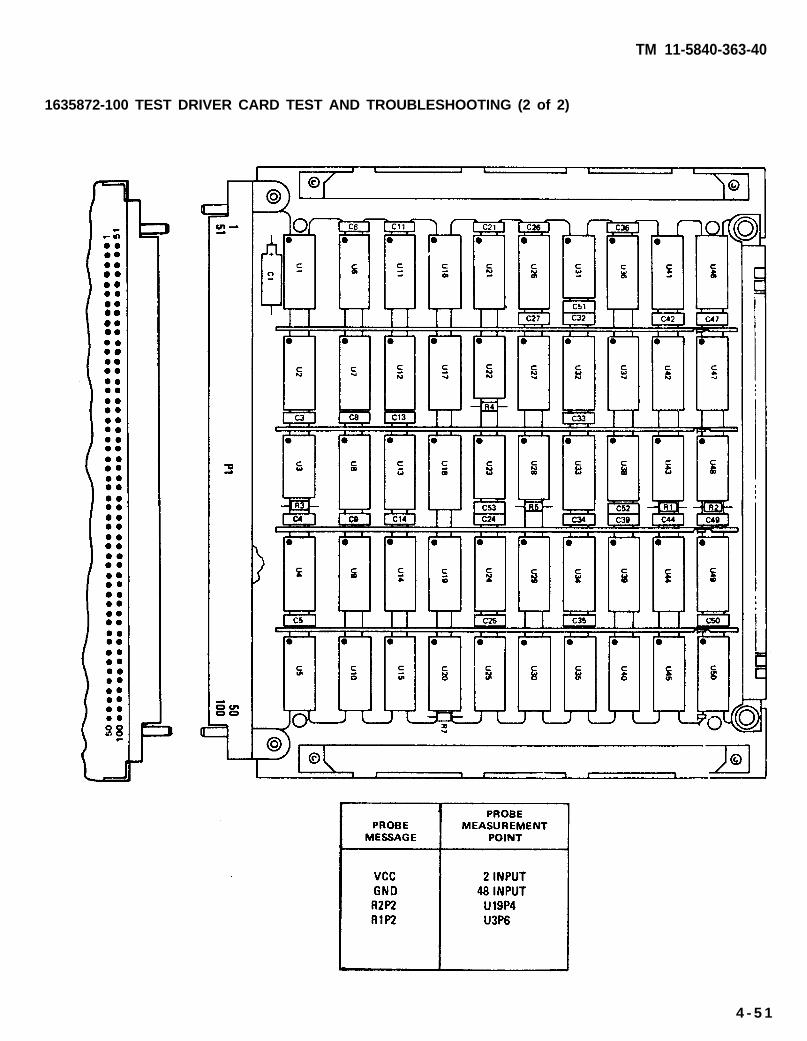
TM 11-5840-363-40
1635872-100 TEST DRIVER CARD TEST AND TROUBLESHOOTING (2 of 2)
4 - 5 1

TM 11-5840-363-40
1635882-100 B-SCOPE VIDEO CONVERTER CARD TEST AND TROUBLESHOOTING (1 of 2)
1. Turn on AN/USM-410(V) tester.a. Perform AN/USM-410(V) tester startup per TM 11-6625-2773-12-1.b. Verify R is displayed on crt. If R is not displayed, turn tester off and restart per TM
11-6625-2773-12-1.c. Type DIR BACKGROUND at terminal and press RETURN key.d. Observe R is displayed on crt.e. At TEST OPERATORS PANEL, select ALL TESTS, VIDEO DISPLAY, and PRINTER.
2. Select test.a. Type TEST 1635882TXX at terminal and press RETURN key. See test program index (page
4-12) for current revision number (the last two digits of the file name).b. Observe the following message on crt. Verify UUT number on top line is correct; disregard
remainder of message, If UUT number is not correct, press and hold COMMAND key andpress HALT key. Release both keys and type in correct test number per step 2a.
TEST-STEP#: LINE#: EQUATE XXUUT: 1635882TXX. IC XX/XX/XX
MEAS VALUE:. . . . . . . . . . . . . . . . . . . . . . . . . . . . . . . . . . . . . . .- RUN TIME SYSTEM REV X.XX -. . . . . . . . . . . . . . . . . . . . . . . . . . . . . . . . . . . . . . .
**PIU CAL APPLIED**BNC CAL APPLIED**LSVSU CAL APPLIED**HSVSU CAL APPLIED
COMPILED USING COMPILER REVISION: X.XXSET SELECTOR SWITCHES. ENTER STARTING TEST STEP:
c. Press PROCEED key to start test.3. Enter part number and manufacturing serial number (MSN).
a. Observe OPERATOR ACTION messages on crt which instruct you to enter the part numberand manufacturing serial number (MSN).
b. Locate these numbers on UUT connector and enter them as directed by crt messages.4. Hook up ID.
a. Observe the following message on crt.OPERATOR ACTIONPERFORM ID HOOKUP AS ILLUSTRATED. SEE TM 11-5840-363-40.
b. Hook up ID per procedure on page 4-18.5. Hook up UUT.
a. Observe the following message on crt.OPERATOR ACTIONPERFORM UUT HOOKUP AS ILLUSTRATED, SEE TM 11-5840-363-40.
Remove ID before performing UUT hookup.
b. Hook up UUT per procedure on page 4-20.6. Test and troubleshoot UUT.
a. Perform any further OPERATOR ACTION messages that appear on crt until test is completeb. Use diagram on opposite page to locate probe points (nodes) and components.
7. Remove UUT and ID per procedure on page 4-24.8. Turn off AN/USM-410(V) tester per shutdown procedure in TM 11-6625-2773-12-1.
4-52 Change 1

TM 11-5840-363-40
1635882-100 B-SCOPE VIDEO CONVERTER CARD TEST AND TROUBLESHOOTING (2 of 2)
I
4 -53

TM 11-5840-363-40
1635883-100 COMPUTER MESSAGE CONTROL CARD TEST AND TROUBLESHOOTING (1 of 2)
1. Turn on AN/USM-410(V) tester.a. Perform AN/USM-410(V) tester startup per TM 11-6625-2773-12-1.b. Verify R is displayed on crt. If R is not displayed, turn tester off and restart per TM
11-6625-2773-12-1.c. Type DlR BACKGROUND at terminal and press RETURN key.d. Observe R is displayed on crt.e. At TEST OPERATORS PANEL, select ALL TESTS, VIDEO DISPLAY, and PRINTER.
2. Select test.a. Type TEST 1635883TXX at terminal and press RETURN key. See test program index (page
4-12) for current revision number (the last two digits of the file name).b. Observe the following message on crt. Verify UUT number on top line is correct; disregard
remainder of message. If UUT number is not correct, press and hold COMMAND key andpress HALT key. Release both keys and type in correct test number per step 2a.
TEST-STEP#: LINE#: EQUATE XXUUT: 1635883TXX. IC XX/XX/XX
MEAS VALUE:. . . . . . . . . . . . . . . . . . . . . . . . . . . . . . . . . . . . . . .- RUN TIME SYSTEM REV X.XX -. . . . . . . . . . . . . . . . . . . . . . . . . . . . . . . . . . . . . . .
**PIU CAL APPLIED**BNC CAL APPLIED**LSVSU CAL APPLIED**HSVSU CAL APPLIED
COMPILED USING COMPILED REVISION: X.XXSET SELECTOR SWITCHES. ENTER STARTING TEST STEP:
c. Press PROCEED key to start test.3. Enter part number and manufacturing serial number (MSN).
a. Observe OPERATOR ACTION messages on crt which instruct you to enter the part numberand manufacturing serial number (MSN).
b. Locate these numbers on UUT connector and enter them as directed by crt messages.4. Hook up ID.
a. Observe the following message on crt.OPERATOR ACTIONPERFORM ID HOOKUP AS ILLUSTRATED. SEE TM 11-5840-363-40.
b. Hook up ID per procedure on page 4-18.5. Hook up UUT.
a. Observe the following message on crt.OPERATOR ACTIONPERFORM UUT HOOKUP AS ILLUSTRATED. SEE TM 11-5840-363-40.
Remove ID before performing UUT hookup.
b. Hook up UUT per procedure on page 4-20.6. Test and troubleshoot UUT.
a. Perform any further OPERATOR ACTION messages that appear on crt until test is complete.b. Use diagram on opposite page to locate probe points (nodes) and components.
7. Remove UUT and ID per procedure on page 4-24.8. Turn off AN/USM-410(V) tester per shutdown procedure in TM 11-6625-2773-12-1.
4-54 Change 1

TM 11-5840-363-40
1635883-1OO COMPUTER MESSAGE CONTROL CARD TEST AND TROUBLESHOOTING (2 of 2)
4-55

TM 11-5840-363-40
1635884-100 CLOCK/TV SYNC GENERATOR CARD TEST AND TROUBLESHOOTING (1 of 2)
1. Turn on AN/USM-410(V) tester.a. Perform AN/USM-410(V) tester startup per TM 11-6625-2773-12-1.b. Verify R is displayed on crt. If R is not displayed, turn tester off and restart per TM
11-6625-2773-12-1.c. Type DIR BACKGROUND at terminal and press RETURN key.d. Observe R is displayed on crt.e. At TEST OPERATORS PANEL, select ALL TESTS, VIDEO DISPLAY, and PRINTER.
2. Select test.a. Type TEST 1635884TXX at terminal and press RETURN key. See test program index (page
4-12) for current revision number (the last two digits of the file name).b. Observe the following message on crt. Verify UUT number on top line is correct; disregard
remainder of message. If UUT number is not correct, press and hold COMMAND key andpress HALT key. Release both keys and type in correct test number per step 2a.
TEST-STEP#: LINE#: EQUATE XXUUT: 1635884TXX. IC XX/XX/XX
MEAS VALUE:. . . . . . . . . . . . . . . . . . . . . . . . . . . . . . . . . . . . . . .- RUN TIME SYSTEM REV X.XX -. . . . . . . . . . . . . . . . . . . . . . . . . . . . . . . . . . . . . . .
**PIU CAL APPLIED**BNC CAL APPLIED**LSVSU CAL APPLIED**HSVSU CAL APPLIED
COMPILED USING COMPILER REVISION: X.XXSET SELECTOR SWITCHES. ENTER STARTING TEST STEP:
c. Press PROCEED key to start test.3. Enter part number and manufacturing serial number (MSN).
a. Observe OPERATOR ACTION messages on crt which instruct you to enter the part numberand manufacturing serial number (MSN).
b. Locate these numbers on UUT connector and enter them as directed by crt messages.4, Hook up ID.
a. Observe the following message on crt.OPERATOR ACTIONPERFORM ID HOOKUP AS ILLUSTRATED. SEE TM 11-5840-363-40.
b. Hook up ID per procedure on page 4-18.5. Hook up UUT.
a. Observe the following message on crt.OPERATOR ACTIONPERFORM UUT HOOKUP AS ILLUSTRATED. SEE TM 11-5840-363-40,
Remove ID before performing UUT hookup.
b. Hook up UUT per procedure on page 4-20.6. Test and troubleshoot UUT.
a. Perform any further OPERATOR ACTION messages that appear on crt until test is complete. b. Use diagram on opposite page to locate probe points (nodes) and components.
7. Remove UUT and ID per procedure on page 4-24.8. Turn off AN/USM-410(V) tester per shutdown procedure in TM 11-6625-2773-12-1.
4-56 Change 1

TM 11-5840-363-40
1635884-100 CLOCK/TV SYNC GENERATOR CARD TEST AND TROUBLESHOOTING (2 of 2)
4-57
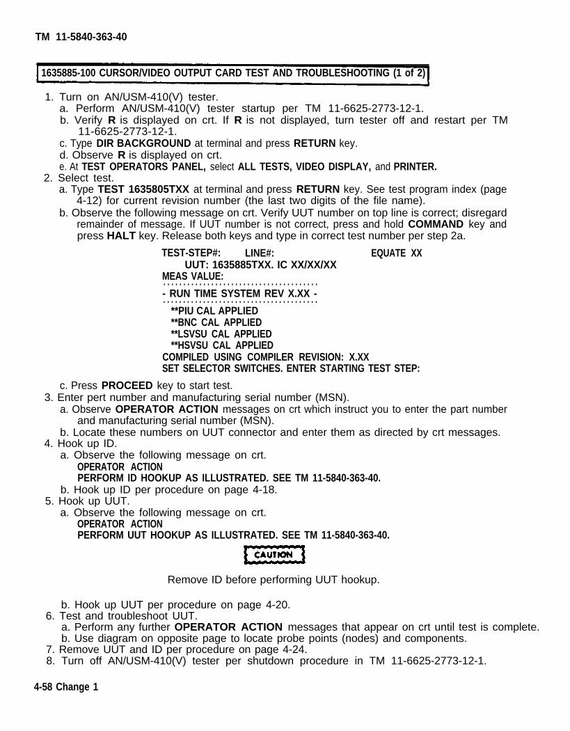
TM 11-5840-363-40
1635885-100 CURSOR/VIDEO OUTPUT CARD TEST AND TROUBLESHOOTING (1 of 2)
1. Turn on AN/USM-410(V) tester.a. Perform AN/USM-410(V) tester startup per TM 11-6625-2773-12-1.b. Verify R is displayed on crt. If R is not displayed, turn tester off and restart per TM
11-6625-2773-12-1.c. Type DIR BACKGROUND at terminal and press RETURN key.d. Observe R is displayed on crt.e. At TEST OPERATORS PANEL, select ALL TESTS, VIDEO DISPLAY, and PRINTER.
2. Select test.a. Type TEST 1635805TXX at terminal and press RETURN key. See test program index (page
4-12) for current revision number (the last two digits of the file name).b. Observe the following message on crt. Verify UUT number on top line is correct; disregard
remainder of message. If UUT number is not correct, press and hold COMMAND key andpress HALT key. Release both keys and type in correct test number per step 2a.
TEST-STEP#: LINE#: EQUATE XXUUT: 1635885TXX. IC XX/XX/XX
MEAS VALUE:. . . . . . . . . . . . . . . . . . . . . . . . . . . . . . . . . . . . . . .- RUN TIME SYSTEM REV X.XX -. . . . . . . . . . . . . . . . . . . . . . . . . . . . . . . . . . . . . . .
**PIU CAL APPLIED**BNC CAL APPLIED**LSVSU CAL APPLIED**HSVSU CAL APPLIED
COMPILED USING COMPILER REVISION: X.XXSET SELECTOR SWITCHES. ENTER STARTING TEST STEP:
c. Press PROCEED key to start test.3. Enter pert number and manufacturing serial number (MSN).
a. Observe OPERATOR ACTION messages on crt which instruct you to enter the part numberand manufacturing serial number (MSN).
b. Locate these numbers on UUT connector and enter them as directed by crt messages.4. Hook up ID.
a. Observe the following message on crt.OPERATOR ACTIONPERFORM ID HOOKUP AS ILLUSTRATED. SEE TM 11-5840-363-40.
b. Hook up ID per procedure on page 4-18.5. Hook up UUT.
a. Observe the following message on crt.OPERATOR ACTIONPERFORM UUT HOOKUP AS ILLUSTRATED. SEE TM 11-5840-363-40.
Remove ID before performing UUT hookup.
b. Hook up UUT per procedure on page 4-20.6. Test and troubleshoot UUT.
a. Perform any further OPERATOR ACTION messages that appear on crt until test is complete. b. Use diagram on opposite page to locate probe points (nodes) and components.
7. Remove UUT and ID per procedure on page 4-24.8. Turn off AN/USM-410(V) tester per shutdown procedure in TM 11-6625-2773-12-1.
4-58 Change 1

TM 11-5840-363-40
1635885-100 CURSOR/VIDEO OUTPUT CARD TEST AND TROUBLESHOOTING (2 of 2)
4 -59

1635886-1OO B-SCOPE VIDEO BUFFER CARD TEST AND TROUBLESHOOTING (1 of 2)
1. Turn on AN/USM-410(V) tester.a. Perform AN/USM-410(V) tester startup per TM 11-6625-2773-12-1.b. Verify R is displayed on crt. If R is not displayed, turn tester off and restart per TM
11-6625-2773-12-1.c. Type DIR BACKGROUND at terminal and press RETURN key.d. Observe R is displayed on crt.e. At TEST OPERATORS PANEL, select ALL TESTS, VIDEO DISPLAY, and PRINTER.
2. Select test.a. Type TEST 1635886TXX at terminal and press RETURN key. See test program index (page
4-1 2) for current revision number (the last two digits of the file name).b. Observe the following message on crt. Verify UUT number on top line is correct; disregard
remainder of message. If UUT number is not correct, press and hold COMMAND key andpress HALT key. Release both keys and type in correct test number per step 2a.
TEST-STEP#: LINE#: EQUATE XXUUT: 1635886TXX. IC XX/XX/XX
MEAS VALUE:. . . . . . . . . . . . . . . . . . . . . . . . . . . . . . . . . . . . . . .- RUN TIME SYSTEM REV X.XX ----------------------------------------
**PIU CAL APPLIED**BNC CAL APPLIED**LSVSU CAL APPLIED**HSVSU CAL APPLIED
COMPILED USING COMPILER REVISION: X.XXSET SELECTOR SWITCHES. ENTER STARTING TEST STEP:
c. Press PROCEED key to start test.3. Enter part number and manufacturing serial number (MSN).
a. Observe OPERATOR ACTION messages on crt which instruct you to enter the part numberand manufacturing serial number (MSN).
b. Locate these numbers on UUT connector and enter them as directed by crt messages.4. Hook up ID.
a. Observe the following message on crt.OPERATOR ACTIONPERFORM ID HOOKUP AS ILLUSTRATED. SEE TM 11-5840-363-40.
b. Hook up ID per procedure on page 4-18.5. Hook up UUT.
a. Observe the following message on crt.OPERATOR ACTIONPERFORM UUT HOOKUP AS ILLUSTRATED. SEE TM 11-5840-363-40.
Remove ID before performing UUT hookup.
b. Hook up UUT per procedure on page 4-20.6. Test and troubleshoot UUT.
a. Perform any further OPERATOR ACTION messages that appear on crt until test is complete. b. Use diagram on opposite page to locate probe points (nodes) and components.
7. Remove UUT and ID per procedure on page 4-24.8. Turn off AN/USM-410(V) tester per shutdown procedure in TM 11-6625-2773-12-1.
4-60 Change 1
TM 11-5840-363-40

TM 11-5840-363-40
1635886-100 B-SCOPE VIDEO BUFFER CARD TEST AND TROUBLESHOOTING (2 of 2)
4-61
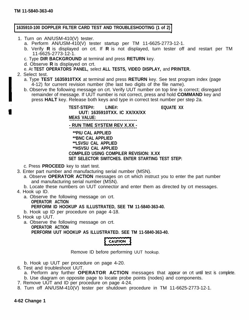
1635910-100 DOPPLER FILTER CARD TEST AND TROUBLESHOOTING (1 of 2)
1. Turn on AN/USM-410(V) tester.a. Perform AN/USM-410(V) tester startup per TM 11-6625-2773-12-1.b. Verify R is displayed on crt. If R is not displayed, turn tester off and restart per TM
11-6625-2773-12-1.c. Type DIR BACKGROUND at terminal and press RETURN key.d. Observe R is displayed on crt.e. At TEST OPERATORS PANEL, select ALL TESTS, VIDEO DISPLAY, and PRINTER.
2. Select test.a. Type TEST 1635910TXX at terminal and press RETURN key. See test program index (page
4-12) for current revision number (the last two digits of the file name).b. Observe the following message on crt. Verify UUT number on top line is correct; disregard
remainder of message. If UUT number is not correct, press and hold COMMAND key andpress HALT key. Release both keys and type in correct test number per step 2a.
TEST-STEP#: LINE#: EQUATE XXUUT: 1635910TXX. IC XX/XX/XX
MEAS VALUE:---------------------------------------- RUN TIME SYSTEM REV X.XX ----------------------------------------
**PIU CAL APPLIED**BNC CAL APPLIED**LSVSU CAL APPLIED**HSVSU CAL APPLIED
COMPILED USING COMPILER REVISION: X.XXSET SELECTOR SWITCHES. ENTER STARTING TEST STEP:
c. Press PROCEED key to start test.3. Enter part number and manufacturing serial number (MSN).
a. Observe OPERATOR ACTION messages on crt which instruct you to enter the part numberand manufacturing serial number (MSN).
b. Locate these numbers on UUT connector and enter them as directed by crt messages.4. Hook up ID.
a. Observe the following message on crt.OPERATOR ACTIONPERFORM ID HOOKUP AS ILLUSTRATED, SEE TM 11-5840-363-40.
b. Hook up ID per procedure on page 4-18.5. Hook up UUT.
a. Observe the following message on crt.OPERATOR ACTIONPERFORM UUT HOOKUP AS ILLUSTRATED. SEE TM 11-5840-363-40.
Remove ID before performing UUT hookup.
b. Hook up UUT per procedure on page 4-20.6. Test and troubleshoot UUT.
a. Perform any further OPERATOR ACTION messages that appear on crt until test is complete.b. Use diagram on opposite page to locate probe points (nodes) and components.
7. Remove UUT and ID per procedure on page 4-24.8. Turn off AN/USM-410(V) tester per shutdown procedure in TM 11-6625-2773-12-1.
4-62 Change 1
TM 11-5840-363-40

TM 11-5840-363-40
163591O-1OO DOPPLER FILTER CARD TEST AND TROUBLESHOOTING (2 of 2)
4 - 6 3

TM 11-5840-363-40
1. Turn on AN/USM-410(V) tester.a. Perform AN/USM-410(V) tester startup per TM 11-6625-2773-12-1.b. Verify R is displayed on crt. If R is not displayed, turn tester off and restart per TM
11-6625-2773-12-1.c, Type DIR BACKGROUND at terminal and press RETURN key.d. Observe R is displayed on crt.
4-12) for current revision number (the last two digits of the file name).b. Observe the following message on crt. Verify UUT number on top line is correct; disregard
remainder of message. If UUT number is not correct, press and hold COMMAND key andpress HALT key. Release both keys and type in correct test number per step 2a.
TEST-STEP#: LINE#: EQUATE XXUUT: 1635911TXX. IC XX/XX/XX
MEAS VALUE:---------------------------------------- RUN TIME SYSTEM REV X.XX ----------------------------------------
**PNJ CAL APPLIED**BNC CAL APPLIED**LSVSU CAL APPLIED**HSVSU CAL APPLIED
COMPILED USING COMPILER REVISION: X.XXSET SELECTOR SWITCHES. ENTER STARTING TEST STEP:
c. Press PROCEED key to start test.3. Enter part number and manufacturing serial number (MSN).
a. Observe OPERATOR ACTION messages on crt which instruct you to enter the part numberand manufacturing serial number (MSN).
b. Locate these numbers on UUT connector and enter them as directed by crt messages.4. Hook up ID.
a. Observe the following message on crt.OPERATOR ACTIONPERFORM ID HOOKUP AS ILLUSTRATED. SEE TM 11-5840-363-40.
b. Hook up ID per procedure on page 4-18.5. Hook up UUT.
a. Observe the following message on crt.OPERATOR ACTIONPERFORM UUT HOOKUP AS ILLUSTRATED. SEE TM 11-5840-363-40.
11635911-100 COEFFICIENT GENERATOR A CARD TEST AND TROUBLESHOOTING (1 of 2)
Remove ID before performing UUT hookup.
b. Hook up UUT per procedure on page 4-20.6. Test and troubleshoot UUT.
a. Perform any further OPERATOR ACTION messages that appear on crt until test is complete.b. Use diagram on opposite page to locate probe points {nodes) and components.
7. Remove UUT and ID per procedure on page 4-24.8. Turn off AN/USM-410(V) tester per shutdown procedure in TM 11-6625-2773-12-1.
4-64 Change 1
e. At TEST OPERATORS PANEL, select ALL TESTS, VIDEO DISPLAY, and PRINTER.2. Select test.
a. Type TEST 1635911TXX at terminal and press RETURN key. See test program index (page

TM 11-5840-363-40
1635911-100 COEFFICIENT GENERATOR A CARD, TEST AND TROUBLESHOOTING (2 of 2)
4 - 6 5

TM 11-5840-363-40
1635912-100 COEFFICIENT GENERATOR B CARD TEST AND TROUBLESHOOTING (1 of 2)
1. Turn on AN/USM-410(V) tester.a. Perform AN/USM-410(V) tester startup per TM 11-6625-2773-12-1.b. Verify R is displayed on crt. If R is not displayed, turn tester off and restart per TM
11-6625-2773-12-1.c. Type DIR BACKGROUND at terminal and press RETURN key.d. Observe R is displayed on crt.e. At TEST OPERATORS PANEL, select ALL TESTS, VIDEO DISPLAY, and PRINTER.
2. Select test. Type TEST 1635912 TXX at terminal and press RETURN key. see test program index (page
4-12) for current revision number (the last two digits of the file name).b. Observe the following message on crt. Verify UUT number on top line is correct; disregard
remainder of message. If UUT number is not correct, press and hold COMMAND key andpress HALT key. Release both keys and type in correct test number per step 2a.
TEST-STEP#: LINE#: EQUATE XX
MEAS VALUE:---------------------------------------- RUN TIME SYSTEM REV X.XX -. . . . . . . . . . . . . . . . . . . . . . . . . . . . . . . . . . . . . . .
** PIU CAL APPLIED** BNC CAL APPLIED** LSVSU CAL APPLIED** HSVSU CAL APPLIED
COMPILED USING COMPILER REVISION: X.XXSET SELECTOR SWITCHES. ENTER STARTING TEST STEP:
c. Press PROCEED key to start test.3. Enter part number and manufacturing serial number (MSN).
a. Observe OPERATOR ACTION messages on crt which instruct you to enter the part numberand manufacturing serial number (MSN).
b. Locate these numbers on UUT connector and enter them as directed by crt messages.4. Hook up ID.
a. Observe the following message on crt.OPERATOR ACTIONPERFORM ID HOOKUP AS ILLUSTRATED. SEE TM 11-5840-363-40.
b. Hook up ID per procedure on page 4-18.5. Hook up UUT.
a. Observe the following message on crt.OPERATOR ACTIONPERFORM UUT HOOKUP AS ILLUSTRATED. SEE TM 11-5840-363-40.
Remove ID before performing UUT hookup.
b. Hook up UUT per procedure on page 4-20.6. Test and troubleshoot UUT.
a. perform any further OPERATOR ACTION messages that appear on crt until test is complete.b. Use diagram on opposite page to locate probe points (nodes) and components.
7. Remove UUT and ID per procedure on page 4-24.8. Turn off AN/USM-410(V) tester per shutdown procedure in TM 11-6625-2773-12-1.
4-66 Change 1
UUT: 1635912TXX. IC XX/XX/XX

TM 11-5840-363-40
1635912-100 COEFFICIENT GENERATOR B CARD TEST AND TROUBLESHOOTING (2 of 2)
4-67

TM 11-5840-363-40
1635913-10O PROCESS CYCLE TIMING CARD TEST AND TROUBLESHOOTING (1 of 2)
1. Turn on AN/USM-410(V) tester.a. Perform AN/USM-410(V) tester startup per TM 11-6625-2773-12-1.b. Verify R is displayed on crt. If R is not displayed, turn tester off and restart per TIu-
11-6625-2773-12-1.c. Type DIR BACKGROUND at terminal and press RETURN key.d. Observe R is displayed on crt.e. At TEST OPERATORS PANEL, select ALL TESTS, VIDEO DISPLAY, and PRINTER.
2. Select test.a. Type TEST 1635913TXX at terminal and press RETURN key. See test program index (page
4-12) for current revision number (the last two digits of the file name).b. Observe the following message on crt. Verify UUT number on top line is correct; disregard
remainder of message. If UUT number is not correct, press and hold COMMAND key andpress HALT key. Release both keys and type in correct test number per step 2a.
TEST-STEP#: LINE#: EQUATE XXUUT: 1635913TXX, IC XX/XX/XX
MEAS VALUE:. . . . . . . . . . . . . . . . . . . . . . . . . . . . . . . . . . . . . . .- RUN TIME SYSTEM REV X.XX -. . . . . . . . . . . . . . . . . . . . . . . . . . . . . . . . . . . . . . .
**PIU CAL APPLIED**BNC CAL APPLIED**LSVSU CAL APPLIED**HSVSU CAL APPLIED
COMPILED USING COMPILER REVISION: X.XXSET SELECTOR SWITCHES. ENTER STARTING TEST STEP:
c. Press PROCEED key to start test.3. Enter part number and manufacturing serial number (MSN).
a. Observe OPERATOR ACTION messages on crt which instruct you to, enter the part numberand manufacturing serial number (MSN).
b. Locate these numbers on UUT connector and enter them as directed by crt messages.4. Hook up ID.
a. Observe the following messaqe on crt.OPERATOR ACTION
5.
PERFORM ID HOOKUP AS ILLUSTRATED. SEE TM 11-5840-363-40.b. Hook up ID per procedure on page 4-18.Hook up UUT.a. Observe the following message on crt.
OPERATOR ACTIONPERFORM UUT HOOKUP AS ILLUSTRATED. SEE TM 11-5840-363-40.
6.
7.8.
Remove ID before performing UUT hookup.
b. Hook up UUT per procedure on page 4-20.Test and troubleshoot UUT.a. Perform any further OPERATOR ACTION messages that appear on crt until test is complete.b. Use diagram on opposite page to locate probe points (nodes) and components.Remove UUT and ID per procedure on page 4-24.Turn off AN/USM-41O(V) tester per shutdown procedure in TM 11-6625-2773-12-1.
Change 14 - 6 8

TM 11-5840-363-40
1635913-100 PROCESS CYCLE TIMING CARD TEST AND TR0UBLESH00TING (2 of 2)
4 - 6 9

TM 11-5840-363-40
1. Turn on AN/USM-410(V) tester.a. Perform AN/USM-410(V) tester startup per TM 11-6625-2773-12-1.b. Verify R is displayed on crt. if R is not displayed, turn tester off and restart per TM,
11-6626-2773-12-1.c. Type DIR BACKGROUND at terminal and press RETURN key.
e. At TEST OPERATORS PANEL, select ALL TESTS, VIDEO DISPLAY, and PRINTER.2. Select test.
4-12) for current revision number (the last two digits of the file name).b. Observe the following message on crt. Verify UUT number on top line is correct; disregard
remainder of message. If UUT number is not correct, press and hold COMMAND key andpress HALT key, Release both keys and type in correct test number per step 2a.
TEST-STEP#: LINE#: EQUATE XXUUT: 1635914TXX. IC XX/XX/XX
MEAS VALUE:----------------------------------------
- - - - - - - - - - - - - - - - - - - - - - - - - - - - - - -**PIU CAL APPLIED**BNC CAL APPLIED**LSVSU CAL APPLIED**HSVSU CAL APPLIED
COMPILED USING COMPILER REVISION: X.XXSET SELECTOR SWITCHES, ENTER STARTING TEST STEP:
c. Press PROCEED key to start test.3. Enter part number and manufacturing serial number (MSN).
a. Observe OPERATOR ACTION messages on crt which instruct you to enter the part numberand manufacturing serial number [MSN).
b. Locate these numbers on UUT connector and enter them as directed by crt messages.4. Hook up ID.
a. Observe the following message on crt.OPERATOR ACTIONPERFORM ID HOOKUP AS ILLUSTRATED, SEE TM 11-5840-363-40.
b. Hook up ID per procedure on page 4-18.5. Hook up UUT.
a. Observe the following message on crt.OPERATOR ACTIONPERFORM UUT HOOKUP AS ILLUSTRATED. SEE TM 11-5840-363-40.
Remove ID before performing UUT hookup.
b. Hook up UUT per procedure on page 4-20.6. Test and troubleshoot UUT.
a. Perform any further OPERATOR ACTION messages that appear on crt until test is complete.b. Use diagram on opposite page to locate probe points (nodes) and components.
7, Remove UUT and ID per procedure on page 4-24.8. Turn off AN/USM-41O(V) tester per shutdown procedure in TM 11-6625-2773-12-1.
4-70 Change 1
1635914-100 THRESHOLD CROSSING DETECTOR CARD TEST AND TROUBLESHOOTING (1 of 2)
a. Type TEST 1635914TXX at terminal and press RETURN key. See test program index (page
-RUN TIME SYSTEM REV X.XX-
d. Observe R is displayed on crt..

TM 11-5840-363-40
1635914-100 THRESHOLD CROSSING DETECTOR CARD TEST AND TROUBLESHOOTING (2 of 2)
4 -71

TM 11-5840-363-40
1635915-100 TARGET DETECTOR CARD TEST AND TROUBLESHOOTING (1 of 2)
1. Turn on AN/USM-410(V) tester.a. Perform AN/USM-410(V) tester startup per TM 11-6625-2773-12-1.b. Verify R is displayed on crt. If R is not displayed, turn tester off and restart per TM
11-6625-2773-12-1.c. Type DIR BACKGROUND at terminal and press RETURN key.d. Observe R is displayed on crt.e. At TEST OPERATORS PANEL, select ALL TESTS, VIDEO DISPLAY, and PRINTER.
2. Select test.. Type TEST 835915TXX at terminal and press RETURN key. See test program index (page
4-12) for current revision number (the last two digits of the file name).b. Observe the following message on crt. Verify UUT number on top line is correct; disregard
remainder of message. If UUT number is not correct, press and hold COMMAND key andpress HALT key. Release both keys and type in correct test number per step 2a.
TEST-STEP#: LINE#: EQUATE XXUUT: 1636915TXX. IC XX/XX/XX
MEAS VALUE:---------------------------------------- RUN TIME SYSTEM REV X.XX -. . . . . . . . . . . . . . . . . . . . . . . . . . . . . . . . . . . . . . .
**PIU CAL APPLIED**BNC CAL APPLIED**LSVSU CAL APPLIED**HSVSU CAL APPLIED
COMPILED USING COMPILER REVISION: X.XXSET SELECTOR SWITCHES. ENTER STARTING TEST STEP:
c. Press PROCEED key to start test.3. Enter part number and manufacturing serial number (MSN).
a. Observe OPERATOR ACTION messages on crt which instruct you to enter the part numberand manufacturing serial number (MSN).
b. Locate these numbers on UUT connector and enter them as directed by crt messages.4. Hook up ID.
a. Observe the following message on crt.OPERATOR ACTIONPERFORM ID HOOKUP AS ILLUSTRATED. SEE TM 11-5840-363-40.
b. Hook up ID per procedure on page 4-18.5. Hook up UUT.
a. Observe the following message on crt.OPERATOR ACTIONPERFORM UUT HOOKUP AS ILLUSTRATED. SEE TM 11-5840-363-40.
Remove ID before performing UUT hookup.
b. Hook up UUT per procedure on page 4-20.6. Test and troubleshoot UUT.
a. Perform any further OPERATOR ACTION messages that appear on crt until test is complete. b. Use diagram on opposite page to locate probe points (nodes) and components.
7. Remove UUT and ID per procedure on page 4-24.8. Turn off AN/USM-410(V) tester per shutdown procedure in TM 11-6625-2773-12-1.
4-72 Change 1

TM 11-5840-363-40
1635915-100 TARGET DETECTOR CARD TEST AND TROUBLESHOOTING (2 of 2)
4-73

TM 11-5840-363-40
1635916-100 PHASE GAIN BIAS CORRECTION CARD TEST AND TROUBLESHOOTING (1 of 2)
1. Turn on AN/USM-410(V) tester.a. Perform AN/USM-410(V) tester startup per TM 11-6625-2773-12-1.b. Verify R is displayed on crt. If R is not displayed, turn tester off and restart per TM
11-6625-2773-12-1.c. Type DIR BACKGROUND at terminal and press RETURN key.d. Observe R is displayed on crt.e. At TEST OPERATORS PANEL, select ALL TESTS, VIDEO DISPLAY, and PRINTER.
2. Select test.
b.
c.
Type TEST 1635916TXX at terminal and press RETURN key. See test program index (page4-12) for current revision number (the last two digits of the file name).
remainder of message. If UUT number is not correct, press and hold COMMAND key andpress HALT key. Release both keys and type in correct test number per step 2a.
TEST-STEP#: LINE#: EQUATE XXUUT: 1635916TXX. IC XX/XX/XX
MEAS VALUE:---------------------------------------- RUN TIME SYSTEM REV X.XX -. . . . . . . . . . . . . . . . . . . . . . . . . . . . . . . . . . . . . . .
**PIU CAL APPLIED **BNC CAL APPLIED**LSVSU CAL APPLIED**HSVSU CAL APPLIED
COMPILED USING COMPILER REVISION: X.XXSET SELECTOR SWITCHES. ENTER STARTING TEST STEP:
Press PROCEED key to start test.3. Enter part number and manufacturing serial number (MSN).
a. Observe OPERATOR ACTION messages on crt which instruct you to enter the part numberand manufacturing serial number (MSN).
b. Locate these numbers on UUT connector and enter them as directed by crt messages.4. Hook up ID.
a. Observe the following message on crt.OPERATOR ACTIONPERFORM ID HOOKUP AS ILLUSTRATED. SEE TM 11-5840-363-40.
b. Hook up ID per procedure on page 4-18.5. Hook up UUT.
a. Observe the following message on crt.OPERATOR ACTIONPERFORM UUT HOOKUP AS ILLUSTRATED. SEE TM 11-5840-363-40.
Remove ID before performing UUT hookup.
b. Hook up UUT per procedure on page 4-20.6. Test and troubleshoot UUT.
a. Perform any further OPERATOR ACTION messages that appear on crt until test is complete.b. Use diagram on opposite page to locate probe points (nodes) and components.
7. Remove UUT and ID per procedure on page 4-24.8. Turn off AN/USM-410(V) tester per shutdown procedure in TM 11-6625-2773-12-1.
4-74 Change 1
a.
Observe the following message on crt. Verify UUT number on top line is correct; disregard

TM 11-5840-363-40
1635916-100 PHASE GAIN BIAS CORRECTION CARD TEST AND TROUBLESHOOTING (2 of 2
4-75

TM 11-5840-363-40
1635917-100 GENERAL PURPOSE FLIP-FLOP CARD TEST AND TROUBLESHOOTING (1 of 2)
1. Turn on AN/USM-410(V) tester.a. Perform AN/USM-410(V) tester startup per TM 11-6625-2773-12-1.b. Verify R is displayed on crt. If R is not displayed, turn tester off and restart per TM
11-6625-2773-12-1.c. Type DIR BACKGROUND at terminal and press RETURN key.d. Observe R is displayed on crt.e. At TEST OPERATORS PANEL, select ALL TESTS, VIDEO DISPLAY, and PRINTER,
2. Select test.a. Type TEST1635917TXX at terminal and press RETURN key. See test program index (page
4-12) for current revision number (the last two digits of the file name).b. Observe the following message on crt. Verify UUT number on top line is correct; disregard
remainder of message. If UUT number is not correct, press and hold COMMAND key andpress HALT key. Release both keys and type in correct test number per step 2a.
TEST-STEP#: LINE#: EQUATE XXUUT: 1635917TXX. IC XX/XX/XX
MEAS VALUE:---------------------------------------- RUN TIME SYSTEM REV X.XX ----------------------------------------
**PIU CAL APPLIED**BNC CAL APPLIED**LSVSU CAL APPLIED**HSVSU CAL APPLIED
COMPILED USING COMPILER REVISION: X.XXSET SELECTOR SWITCHES. ENTER STARTING TEST STEP:
c. Press PROCEED key to start test.3. Enter part number and manufacturing serial number (MSN).
a. Observe OPERATOR ACTION messages on crt which instruct you to enter the part numberand manufacturing serial number (MSN).
b. Locate these numbers on UUT connector and enter them as directed by crt messages.4. Hook up ID.
a. Observe the following message on crt.OPERATOR ACTIONPERFORM ID HOOKUP AS ILLUSTRATED. SEE TM 11-5840-363-40.
b. Hook up ID per procedure on page 4-18.5. Hook up UUT.
a. Observe the following message on crt.OPERATOR ACTIONPERFORM UUT HOOKUP AS ILLUSTRATED. SEE TM 11-5840-363-40.
Remove ID before performing UUT hookup.
b. Hook up UUT per procedure on page 4-20.6. Test and troubleshoot UUT.
a. Perform any further OPERATOR ACTION messages that appear on crt until test is complete.b. Use diagram on opposite page to locate probe points (nodes) and components.
7. Remove UUT and ID per procedure on page 4-24.8. Turn off AN/USM-410(V) tester per shutdown procedure in TM 11-6625-2773-12-1.
4-76 Change 1

TM 11-5840-363-40
1635917-100 GENERAL PURPOSE FLIP-FLOP CARD TEST AND TROUBLESHOOTING (2 of 2)
4-77

TM 11-5840-363-40
1635918-100 PULSED INTERFERENCE DETECTOR CARD TEST AND TROUBLESHOOTING (1 of 2)
1. Turn on AN/USM-410(V) tester.a. Perform AN/USM-410(V) tester startup per TM 11-6625-2773-12-1.b. Verify R is displayed on crt. If R is not displayed, turn tester off and restart per TM
11-6625-2773-12-1.c. Type DIR BACKGROUND at terminal and press RETURN key.d. Observe R is displayed on crt.e. At TEST OPERATORS PANEL, select ALL TESTS, VIDEO DISPLAY, and PRINTER.
2. Select test.a. Type TEST 1635918TXX at terminal and press RETURN key. See test program index (page
4-12) for current revision number (the last two digits of the file name).b. Observe the following message on crt. Verify UUT number on top line is correct; disregard
remainder of message. If UUT number is not correct, press and hold COMMAND key andpress HALT key. Release both keys and type in correct test number per step 2a.
TEST-STEP#: LINE#: EQUATE XXUUT: 1635918TXX. IC XX/XX/XX
MEAS VALUE:. . . . . . . . . . . . . . . . . . . . . . . . . . . . . . . . . . . . . . .- RUN TIME SYSTEM REV X.XX -. . . . . . . . . . . . . . . .
**PIU CAL APPLIED‘*BNC CAL APPLIED**LSVSU CAL APPLIED**HSVSU CAL APPLIED
COMPILED USING COMPILER REVISION: X.XXSET SELECTOR SWITCHES. ENTER STARTING TEST STEP:
c. Press PROCEED key to start test.3. Enter part number and manufacturing serial number (MSN).
a. Observe OPERATOR ACTION messages on crt which instruct you to enter the part numberand manufacturing serial number (MSN).
b. Locate these numbers on UUT connector and enter them as directed by crt messages.4. Hook Up ID.
a. Observe the following message on crt.OPERATOR ACTIONPERFORM ID HOOKUP AS ILLUSTRATED. SEE TM 11-5840-363-40.
b. Hook up ID per procedure on page 4-18.5. Hook Up UUT.
a. Observe the following message on crt.OPERATOR ACTIONPERFORM UUT HOOKUP AS ILLUSTRATED. SEE TM 11-5840-363-40.
Remove ID before performing UUT hookup.
b. Hook up UUT per procedure on page 4-20.6. Test and troubleshoot UUT.
a. perform any further OPERATOR ACTION messages that appear on crt until test is complete.b. Use diagram on opposite page to locate probe points (nodes) and components.
7. Remove UUT and ID per procedure on page 4-24.8. Turn off AN/USM-410(V) tester per shutdown procedure in TM 11-6625-2773-12-1.
4-78 Change 1

TM 11-5840-363-40
1635918-100 PULSED INTERFERENCE DETECTOR CARD TEST AND TROUBLESHOOTING (2 of 2)
4-79

1635919-100 TARGET/BITE BUFFER CARD TEST AND TROUBLESHOOTING (1 of 2
1. Turn on AN/USM-410(V) tester.a. Perform AN/USM-410(V) tester startup per TM11-6625-2773-12-1.b. Verify R is displayed on crt. If R is not displayed, turn tester off and restart per TM
11-6625-2773-12-1.c. Type DIR BACKGROUND at terminal and press RETURN key.d. Observe R is displayed on crt.e. At TEST OPERATORS PANEL, select ALL TESTS, VIDEO DISPLAY, and PRINTER.
2. Select test.a. Type TEST 1635919TXX at terminaI and press RETURN key. See test program index (page
4-12) for current revision number (the last two digits of the file name).b. Observe the following message on crt. Verify UUT number on top line is correct; disregard
remainder of message, If UUT number is not correct, press and hold COMMAND key andpress HALT key. Release both keys and type in correct test number per step 2a.
TEST-STEP#: LINE#: EQUATE XXUUT: 1635919TXX. IC XX/XX/XX
MEAS VALUE:. . . . . . . . . . . . . . . . . . . . . . . . . . . . . . . . . . . . . . .- RUN TIME SYSTEM REV X.XX -. . . . . . . . . . . . . . . . . . . . . . . . . . . . . . . . . . . . . . .
**PIU CAL APPLIED **BNC CAL APPLIED**LWSU CAL APPLIED **HSVSU CAL APPLIED
COMPILED USING COMPILER REVISION: X.XXSET SELECTOR SWITCHES. ENTER STARTING TEST STEP:
c. Press PROCEED key to start test.3. Enter part number and manufacturing serial number (MSN).
a. Observe OPERATOR ACTION messages on crt which instruct you to enter the part numberand manufacturing serial number (MSN).
b. Locate these numbers on UUT connector and enter them as directed by crt messages.4. Hook up ID.
a. Observe the following message on crt.OPERATOR ACTIONPERFORM ID HOOKUP AS ILLUSTRATED. SEE TM 11-5840-363-40.
b. Hook up ID per procedure on page 4-18.5. Hook up UUT.
a. Observe the following message on crt.OPERATOR ACTIONPERFORM UUT HOOKUP AS ILLUSTRATED. SEE TM 11-5840-363-40.
Remove ID before performing UUT hookup.
b. Hook up UUT per procedure on page 4-20.6. Test and troubleshoot UUT.
a. perform any further OPERATOR ACTlON messages that appear on crt until test is complete.b. Use diagram on opposite page to locate probe points (nodes) and components.
7, Remove UUT and ID) per procedure on page 4-24.8. Turn off AN/USM-410(V) tester per shutdown procedure in TM 11-6625-2773-12-1.
4-80 Change 1
TM 11-5840-363-40

TM 11-5840-363-40
1635919-100 TARGET/BITE BUFFER CARD TEST AND TROUBLESHOOTING (2 of 2)
4 - 8 1
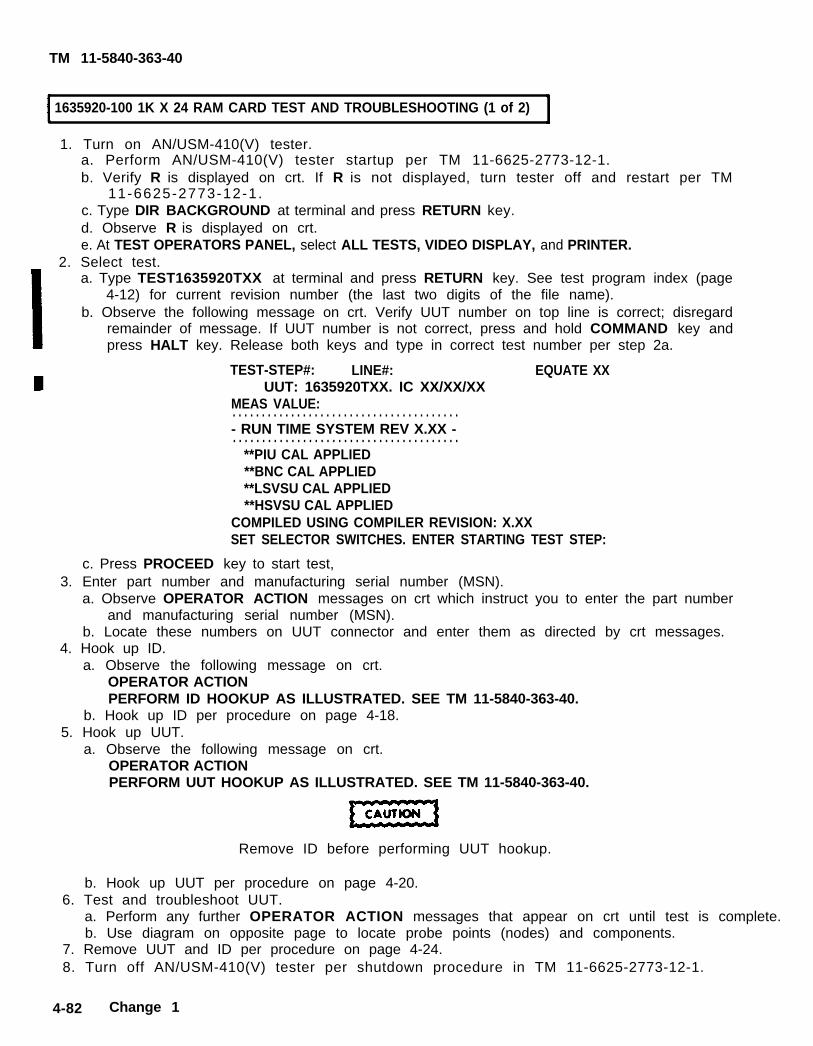
TM 11-5840-363-40
1635920-100 1K X 24 RAM CARD TEST AND TROUBLESHOOTING (1 of 2)
1. Turn on AN/USM-410(V) tester.a. Perform AN/USM-410(V) tester startup per TM 11-6625-2773-12-1.b. Verify R is displayed on crt. If R is not displayed, turn tester off and restart per TM
11-6625-2773-12-1.c. Type DIR BACKGROUND at terminal and press RETURN key.d. Observe R is displayed on crt.e. At TEST OPERATORS PANEL, select ALL TESTS, VIDEO DISPLAY, and PRINTER.
2. Select test.a. Type TEST1635920TXX at terminal and press RETURN key. See test program index (page
4-12) for current revision number (the last two digits of the file name).b. Observe the following message on crt. Verify UUT number on top line is correct; disregard
remainder of message. If UUT number is not correct, press and hold COMMAND key andpress HALT key. Release both keys and type in correct test number per step 2a.
TEST-STEP#: LINE#: EQUATE XXUUT: 1635920TXX. IC XX/XX/XX
MEAS VALUE:. . . . . . . . . . . . . . . . . . . . . . . . . . . . . . . . . . . . . . .- RUN TIME SYSTEM REV X.XX -. . . . . . . . . . . . . . . . . . . . . . . . . . . . . . . . . . . . . . .
**PIU CAL APPLIED**BNC CAL APPLIED**LSVSU CAL APPLIED**HSVSU CAL APPLIED
COMPILED USING COMPILER REVISION: X.XXSET SELECTOR SWITCHES. ENTER STARTING TEST STEP:
c. Press PROCEED key to start test,3. Enter part number and manufacturing serial number (MSN).
a. Observe OPERATOR ACTION messages on crt which instruct you to enter the part numberand manufacturing serial number (MSN).
b. Locate these numbers on UUT connector and enter them as directed by crt messages.4. Hook up ID.
a. Observe the following message on crt.OPERATOR ACTIONPERFORM ID HOOKUP AS ILLUSTRATED. SEE TM 11-5840-363-40.
b. Hook up ID per procedure on page 4-18.5. Hook up UUT.
a. Observe the following message on crt.OPERATOR ACTIONPERFORM UUT HOOKUP AS ILLUSTRATED. SEE TM 11-5840-363-40.
Remove ID before performing UUT hookup.
b. Hook up UUT per procedure on page 4-20.6. Test and troubleshoot UUT.
a. Perform any further OPERATOR ACTION messages that appear on crt until test is complete.b. Use diagram on opposite page to locate probe points (nodes) and components.
7. Remove UUT and ID per procedure on page 4-24.8. Turn off AN/USM-410(V) tester per shutdown procedure in TM 11-6625-2773-12-1.
4-82 Change 1

TM 11-5840-363-40
-1635920-100 1K X 24 RAM CARD TEST AND TROUBLESHOOTING (2 of 2)
4-83

11635921-100 READ CONTROL CARD TEST AND TROUBLESHOOTING (1 of 2)
1. Turn on AN/USM-410(V) tester.a. Perform AN/USM-410(V) tester startup per TM 11-6625-2773-12-1.b. Verify R is displayed on crt. If R is not displayed, turn tester off and restart per TM
11-6625-2773-12-1.c. Type DIR BACKGROUND at terminal and press RETURN key.d. Observe R is displayed on crt.e. At TEST OPERATORS PANEL, select ALL TESTS, VIDEO DISPLAY, and PRINTER.
2. Select test. a. Type TEST 1635921TXX at terminal and press RETURN key. See test program index (page
4-12) for current revision number (the last two digits of the fits name). b. Observe the following message on crt. Verify UUT number on top line is correct; disregard
remainder of message. If UUT number is not correct, press and hold COMMAND key andpress HALT key. Release both keys and type in correct test number per step 2a.
TEST-STEP#: LINE#: EQUATE XXUUT: 1635921TXX. IC XX/XX/XX
MEAS VALUE:---------------------------------------- RUN TIME SYSTEM REV X.XX ----------------------------------------
**PIU CAL APPLIED**BNC CAL APPLIED**LSVSU CAL APPLIED**HSVSU CAL APPLIED
COMPILED USING COMPILER REVISION: X.XXSET SELECTOR SWITCHES. ENTER STARTING TEST STEP:
c. Press PROCEED key to start test.3. Enter part number and manufacturing serial number (MSN).
a. Observe OPERATOR ACTION messages on crt which instruct you to enter the part numberand manufacturing serial number (MSN).
b. Locate these numbers on UUT connector and enter them as directed by crt messages.4. Hook up ID.
a. Observe the following message on crt.OPERATOR ACTIONPERFORM ID HOOKUP AS ILLUSTRATED. SEE TM 11-5840-363-40.
b. Hook up ID per procedure on page 4-18.5. Hook up UUT.
a. Observe the following message on crt.OPERATOR ACTIONPERFORM UUT HOOKUP AS ILLUSTRATED. SEE TM 11-5840-363-40,
Remove ID before performing UUT hookup.
b. Hook up UUT per procedure on page 4-20.6. Test and troubleshoot UUT.
a. Perform any further OPERATOR ACTION messages that appear on crt until testis complete.b. Use diagram on opposite page to locate probe points (nodes) and components.
7. Remove UUT and ID per procedure on page 4-24.8. Turn off AN/USM-410(V) tester per shutdown procedure in TM 11-6625-2773-12-1.
4-84 Change 1
TM 11-5840-363-40

TM 11-5840-363-40
1635921-100 READ CONTROL CARD TEST AND TROUBLESHOOTING (2 of 2)
4-85

TM 11-5840-363-40
1635922-100 COMMAND DATA CARD TEST AND TROUBLESHOOTING (1 of 2)]
1. Turn on AN/USM-410(V) tester.a. Perform AN/USM-410(V) tester startup per TM 11-6625-2773-12-1.b. Verify R is displayed on crt. If R is not displayed, turn tester off and restart per TM
11-6625-2773-12-1.c. Type DIR BACKGROUND at terminal and press RETURN key.d. Observe R is displayed on crt.e. At TEST OPERATORS PANEL, select ALL TESTS, VIDEO DISPLAY, and PRINTER.
2. Select test.a. Type TEST 1635922TXX at terminal and press RETURN key. See test program index (page
4-12) for current revision number (the last two digits of the file name).b. Observe the following message on crt. Verify UUT number on top line is correct; disregard
remainder of message. If UUT number is not correct, press and hold COMMAND key andpress HALT key. Release both keys and type in correct test number per step 2a.
TEST-STEP#: LINE#: EQUATE XXUUT: 1635922TXX. IC XX/XX/XX
MEAS VALUE:. . . . . . . . . . . . . . . . . . . . . . . . . . . . . . . . . . . . . . .- RUN TIME SYSTEM REV X.XX -. . . . . . . . . . . . . . . . . . . . . . . . . . . . . .
**PIU CAL APPLIED**BNC CAL APPLIED**LSVSV CAL APPLIED**HSVSU CAL APPLIED
COMPILED USING COMPILER REVISION: X.XXSET SELECTOR SWITCHES. ENTER STARTING TEST STEP:
c. Press PROCEED key to start test.3. Enter part number and manufacturing serial number (MSN).
a. Observe OPERATOR ACTION messages on crt which instruct you to enter the part numberand manufacturing serial number (MSN).
b. Locate these numbers on UUT connector and enter them as directed by crt messages.4. Hook up ID.
a. Observe the following message on crt.OPERATOR ACTIONPERFORM ID HOOKUP AS ILLUSTRATED. SEE TM 11-5840-363-40.
b. Hook up ID per procedure on page 4-18.5. Hook up UUT.
a. Observe the following message on crt.OPERATOR ACTIONPERFORM UUT HOOKUP AS ILLUSTRATED. SEE TM 11-5840-363-40.
Remove ID before performing UUT hookup.
b. Hook up UUT per procedure on page 4-20.6. Test and troubleshoot UUT.
a. Perform any further OPERATOR ACTION messages that appear on crt until test is complete.b. Use diagram on opposite page to locate probe points (nodes) and components.
7. Remove UUT and ID per procedure on page 4-24.8. Turn off AN/USM-410(V) tester per shutdown procedure in TM 11-6625-2773-12-1.
4-86 Change 1

TM 11-5840-363-40
1635922-100 COMMAND DATA CARD TEST AND TROUBLESHOOTING (2 of 2)
4-87

TM 11-5840-363-40
1635923-100 COLLECT CYCLE TIMING CARD TEST AND TROUBLESHOOTING (1 Of 2)
1.
2.
3.
4.
5.
6.
7.8.
4-88
Turn on AN/USM-410(V) tester.a. Perform AN/USM-410(V) tester startup per TM 11-6625-2773-12-1.b. Verify R is displayed on crt. If R is not displayed, turn tester off and restart per TM
11-6625-2773-12-1.c. Type DIR BACKGROUND at terminal and press RETURN key.d. Observe R is displayed on crt.e. At TEST OPERATORS PANEL, select ALL TESTS, VIDEO DISPLAY, and PRINTER.Select test.a. Type TEST 1635923TXX at terminal and press RETURN key. See test program index (page
4-12) for current revision number (the last two digits of the file name).b. Observe the following message on crt. Verify UUT number on top line is correct; disregard
remainder of message. If UUT number is not correct, press and hold COMMAND key andpress HALT key. Release both keys and type in correct test number per step 2a.
TEST-STEP#: LINE#: EQUATE XXUUT: 1635923TXX. IC XX/XX/XX
MEAS VALUE:---------------------------------------- RUN TIME SYSTEM REV X.XX ----------------------------------------
**PIU CAL APPLIED **BNC CAL APPLIED **LSVSU CAL APPLIED **HSVSU CAL APPLIED
COMPILED USING COMPILER REVISION: X.XXSET SELECTOR SWITCHES. ENTER STARTING TEST STEP:
c. Press PROCEED key to start test.Enter part number and manufacturing serial number (MSN).a. Observe OPERATOR ACTION messages on crt which instruct you to enter the part number
and manufacturing serial number (MSN).b. Locate these numbers on UUT connector and enter them as directed by crt messages.Hook up ID.a. Observe the following message on crt.
OPERATOR ACTIONPERFORM ID HOOKUP AS ILLUSTRATED. SEE TM 11-5840-363-40.
b. Hook up ID per procedure on page 4-18.Hook up UUT.a, Observe the following message on crt.
OPERATOR ACTIONPERFORM UUT HOOKUP AS ILLUSTRATED. SEE TM 11-5840-363-40.
Remove ID before performing UUT hookup.
b. Hook up UUT per procedure on page 4-20.Test and troubleshoot UUT.a. Perform any further OPERATOR ACTION messages that appear on crt until test is complete.b. Use diagram on opposite page to locate probe points (nodes) and components.Remove UUT and ID per procedure on page 4-24.Turn off AN/USM-410(V) tester per shutdown procedure in TM 11-6625-2773-12-1.
Change 1

TM 11-5840-363-40
1635923-100 COLLECT CYCLE TIMING CARD TEST AND TROUBLESHOOTING (2 of 2)
4-89

TM 11-5840-363-40
1635924-100 TIMING DECODER NO. 1 CARD TEST AND TROUBLESHOOTING (1 of 2)
1. Turn on AN/USM-410(V) tester,a. Perform AN/USM-410(V) tester startup per TM 11-6625-2773-12-1.b. Verify R is displayed on crt. If R is not displayed, turn tester off and restart per TM
11-6625-2773-12-1.c. Type DIR BACKGROUND at terminal and press RETURN key.d. Observe R is displayed on crt.e. At TEST OPERATORS PANEL, select ALL TESTS, VIDEO DISPLAY, and PRINTER.
2. Select test.a. Type TEST 1635924TXX at terminal and press RETURN key. See test program index [page
4-12) for current revision number (the last two digits of the file name).b. Observe the following message on crt. Verify UUT number on top line is correct; disregard
remainder of message. If UUT number is not correct, press and hold COMMAND key andpress HALT key. Release both keys and type in correct test number per step 2a.
TEST-STEP#: LINE#: EQUATE XXUUT: 1635924TXX. IC XX/XX/XX
MEAS VALUE:. . . . . . . . . . . . . . . . . . . . . . . . . . . . . . . . . . . . . . .- RUN TIME SYSTEM REV X.XX -. . . . . . . . . . . . . . . . . . . . . . . . . . . . . . . . . . . . . . .
**PIU CAL APPLIED**BNC CAL APPLIED**LSVSU CAL APPLIED**HSVSU CAL APPLIED
COMPILED USING COMPILER REVISION: X.XXSET SELECTOR SWITCHES. ENTER STARTING TEST STEP:
c. Press PROCEED key to start test.3. Enter part number and manufacturing serial number (MSN).
a. Observe OPERATOR ACTION messages on crt which instruct you to enter the part numberand manufacturing serial number (MSN).
b. Locate these numbers on UUT connector and enter them as directed by crt messages.4. Hook up ID.
a. Observe the following message on crt.OPERATOR ACTIONPERFORM ID HOOKUP AS ILLUSTRATED. SEE TM 11-5840-363-40.
b. Hook up lD per procedure on page 4-18.5. Hook up UUT.
a. Observe the following message on crt.OPERATOR ACTIONPERFORM UUT HOOKUP AS ILLUSTRATED, SEE TM 11-5840-363-40.
Remove ID before performing UUT hookup.
b. Hook up UUT per procedure on page 4-20.6. Test and troubleshoot UUT.
a. Perform any further OPERATOR ACTION messages that appear on crt until test is complete.b. Use diagram on opposite page to locate probe points (nodes) and components.
7. Remove UUT and ID per procedure on page 4-24.8. Turn off AN/USM-410(V) tester per shutdown procedure in TM 11-6625-2773-12-1.
4-90 Change 1

TM 11-5840-363-40
1635924-100 TIMING DECORDER NO. 1 CARD TEST AND TROUBLESHOOTING (2 of 2)
4 - 9 1

TM 11-5840-363-40
1635925-100 CLOCK OSCILLATOR CARD TEST AND TROUBLESHOOTING (1 of 2)
1. Turn on AN/USM-410(V) tester.a. Perform AN/USM-410(V) tester startup per TM 11-6625-2773-12-1.b. Verify R is displayed on crt. If R is not displayed, turn tester off and restart per TM
11-6625-2773-12-1.c. Type DIR BACKGROUND at termina[ and press RETURN key.d. Observe R is displayed on crt.e. At TEST OPERATORS PANEL, select ALL TESTS, VIDEO DISPLAY, and PRINTER.
2. Select test.a. Type TEST 1635925TXX at terminal and press RETURN key. see test program index (page
4-12) for current revision number (the last two digits of the file name).b. Observe the following message on crt. Verify UUT number on top line is correct; disregard
remainder of message. If UUT number is not correct, press and hold COMMAND key andpress HALT key. Release both keys and type in correct test number per step 2a.
TEST-STEP#: LINE#: EQUATE XXUUT: 1635925TXX. IC XX/XX/XX
MEAS VALUE:---------------------------------------- RUN TIME SYSTEM REV X.XX ----------------------------------------
**PIU CAL APPLIED **BNC CAL APPLIED **LSVSU CAL APPLIED **HSVSU CAL APPLIED
COMPILED USING COMPILER REVISION: X.XXSET SELECTOR SWITCHES. ENTER STARTING TEST STEP:
c. Press PROCEED key to start test.3. Enter part number and manufacturing serial number (MSN).
a. Observe OPERATOR ACTION messages on crt which instruct you to enter the part numberand manufacturing serial number (MSN).
b. Locate these numbers on UUT connector and enter them as directed by crt messages.4. Hook up ID.
a. Observe the following message on crt.OPERATOR ACTIONPERFORM ID HOOKUP AS ILLUSTRATED. SEE TM 11-5840-363-40.
b. Hook up ID per procedure on page 4-18.5. Hook up UUT.
a. Observe the following message on crt.OPERATOR ACTIONPERFORM UUT HOOKUP AS ILLUSTRATED. SEE TM 11-5840-363-40.
Remove ID before performing UUT hookup.
b. Hook up UUT per procedure on page 4-20.6. Test and troubleshoot UUT.
a. Perform any further OPERATOR ACTION messages that appear on crt until test is complete.b. Use diagram on opposite page to locate probe points (nodes) and components.
7. Remove UUT and ID per procedure on page 4-24.8. Turn off AN/USM-410(V) tester per shutdown procedure in TM 11-6625-2773-12-1.
4-92 Change 1
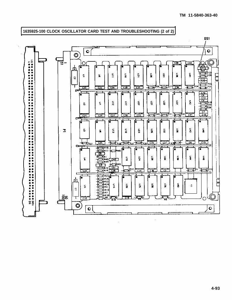
TM 11-5840-363-40
1635925-100 CLOCK OSCILLATOR CARD TEST AND TROUBLESHOOTING (2 of 2)
4-93

TM 11-5840-363-40
1635926-100 FRAME DECODER CARD TEST AND TROUBLESHOOTING (1 of 2)
1. Turn on AN/USM-410(V) tester.a. Perform AN/USM-410(V) tester startup per TM 11-6625-2773-12-1.b. Verify R is displayed on crt. If R is not displayed, turn tester off and restart per TM
11-6625-2773-12-1.c. Type DIR BACKGROUND at terminal and press RETURN key.d. Observe R is displayed on crt.e. At TEST OPERATORS PANEL, select ALL TESTS, VIDEO DISPLAY, and PRINTER.
2. Select test.a. Type TEST 1635926 TXX at terminal and press RETURN key, See test program index (page
4-12) for current revision number (the last two digits of the file name).b. Observe the following message on crt. Verify UUT number on top line incorrect; disregard
remainder of message. If UUT number is not correct, press and hold COMMAND key andpress HALT key. Release both keys and type in correct test number per step 2a.
TEST-STEP#: LINE#: EOUATE XXUUT: 1635926TXX. IC XX/XX/XX
MEAS VALUE:---------------------------------------- RUN TIME SYSTEM REV X.XX ----------------------------------------
**PIU CAL APPLIED **BNC CAL APPLIED **LSVSU CAL APPLIED **HSVSU CAL APPLIED
COMPILED USING COMPILER REVISION: X.XXSET SELECTOR SWITCHES. ENTER STARTING TEST STEP:
c. Press PROCEED key to start test.3. Enter part number and manufacturing serial number (MSN).
a. Observe OPERATOR ACTION messages on crt which instruct you to enter the part numberand manufacturing serial number (MSN).
b. Locate these numbers on UUT connector and enter them as directed by crt messages.4. Hook up ID.
a. Observe the following message on crt.OPERATOR ACTIONPERFORM ID HOOKUP AS ILLUSTRATED. SEE TM 11-5840-363-40.
b. Hook up ID per procedure on page 4-18.5. Hook up UUT.
a. Observe the following message on crt.OPERATOR ACTIONPERFORM UUT HOOKUP AS ILLUSTRATED. SEE TM 11-5840-363-40.
Remove ID before performing UUT hookup.
b. Hook up UUT per procedure on page 4-20.6. Test and troubleshoot UUT.
a. Perform any further OPERATOR ACTION messages that appear on crt until test is complete.b. Use diagram on opposite page to locate probe points (nodes) and components.
7. Remove UUT and ID per procedure on page 4-24.8. Turn off AN/USM-410(V) tester per shutdown procedure in TM 11-6625-2773-12-1.
4-94 Change 1

TM 11-5840-363-40
1635926-100 FRAME DECODER CARD TEST AND TROUBLESHOOTING (2 of 2)
4-95

TM 11-5840-363-40
1635927-100 DATA BUS DECODER CARD TEST AND TROUBLESHOOTlNG (1 of 2)
1. Turn on AN/USM-410(V) tester.a. Perform AN/USM-410(V) tester startup per TM 11-6625-2773-12-1.b. Verify R is displayed on crt. If R is not displayed, turn tester off and restart per TM
11-6625-2773-12-1.c. Type DIR BACKGROUND at terminal and press RETURN key.d. Observe R is displayed on crt.e. At TEST OPERATORS PANEL, select ALL TESTS, VIDEO DISPLAY, and PRINTER.
2. Select test.a. Type TEST 1635927TXX at terminal and press RETURN key. See test program index (page
4-12) for current revision number (the last two digits of the file name).b. Observe the following message on crt. Verify UUT number on top line is correct; disregard
remainder of message. If UUT number is not correct, press and hold COMMAND key andpress HALT key. Release both keys and type in correct test number per step 2a.
TEST-STEP#: LINE#: EQUATE XXUUT: 1635927TXX. IC XX/XX/XX
MEAS VALUE:---------------------------------------- RUN TIME SYSTEM REV X.XX -. . . . . . . . . . . . . . . . . . . . . . . . . . . . . . . . . . . . . . .
**PIU CAL APPLIED**BNC CAL APPLIED**LSVSU CAL APPLIED**HSVSU CAL APPLIED
COMPILED USING COMPILER REVISION: X.XXSET SELECTOR SWITCHES. ENTER STARTING TEST STEP:
c. Press PROCEED key to start test.3. Enter part number and manufacturing serial number (MSN).
a. Observe OPERATOR ACTION messages on crt which instruct you to enter the part numberand manufacturing serial number (MSN).
b. Locate these numbers on UUT connector and enter them as directed by crt messages.4. Hook up ID.
a. Observe the following message on crt.OPERATOR ACTIONPERFORM ID HOOKUP AS ILLUSTRATED. SEE TM 11-5840-363-40.
b. Hook up ID per procedure on page 4-18.5. Hook up UUT.
a. Observe the following message on crt.OPERATOR ACTIONPERFORM UUT HOOKUP AS ILLUSTRATED. SEE TM 11-5840-363-40.
Remove ID before performing UUT hookup.
b. Hook up UUT per procedure on page 4-20.6. Test and troubleshoot UUT.
a. Perform any further OPERATOR ACTION messages that appear on crt until test is complete.b. Use diagram on opposite page to locate probe points (nodes) and components.
7. Remove UUT and ID per procedure on page 4-24.8. Turn off AN/USM-410(V) tester per shutdown procedure in TM 11-6625-2773-12-1.
4-96 Change 1

TM 11-5840-363-40
1635927-100 DATA BUS DECODER CARD TEST AND TROUBLESHOOTING (2 of 2)
4 - 9 7

1635928-100 MTI-CANCELLER CARD TEST AND TROUBLESHOOTING (1 of 2)
1. Turn on AN/USM-410(V) tester.a. Perform AN/USM-410(V) tester startup per TM 11-6625-2773-12-1.b. Verify R is displayed on crt. If R is not displayed, turn tester off and restart per TM
11-6625-2773-12-1.c. Type DIR BACKGROUND at terminal and press RETURN key.d. Observe R is displayed on crt.e. At TEST OPERATORS PANEL, select ALL TESTS, VIDEO DISPLAY, and PRINTER.
2. Select test.a.
b.
c.
Type TEST 1635928TXX at terminal and press RETURN key. See test program index (page4-12) for current revision number (the last two digits of the file name).Observe the following message on crt. Verify UUT number on top line is correct; disregardremainder of message. If UUT number is not correct, press and hold COMMAND key andpress HALT key, Release both keys and type in correct test number per step 2a.
TEST-STEP#: LINE#: EQUATE XXUUT: 1635928TXX. IC XX/XX/XX
MEAS VALUE:. . . . . . . . . . . . . . . . . . . . . . . . . . . . . . . . . . . . . . .- RUN TIME SYSTEM REV X,XX -. . . . . . . . . . . . . . . . . . . . . . . . . . . . . . . . . . . . . . .
**PIU CAL APPLIED**BNC CAL APPLIED**LSVSU CAL APPLIED**HSVSU CAL APPLIED
COMPILED USING COMPILER REVISION: X.XXSET SELECTOR SWITCHES. ENTER STARTING TEST STEP:
Press PROCEED key to start test.3. Enter part number and manufacturing serial number (MSN).
a. Observe OPERATOR ACTION messages on crt which instruct you to enter the part numberand manufacturing serial number (MSN).
b. Locate these numbers on UUT connector and enter them as directed by crt messages.4. Hook up ID.
a. Observe the following message on crt.OPERATOR ACTIONPERFORM ID HOOKUP AS ILLUSTRATED. SEE TM 11-5840-363-40.
5.b. Hook up ID per procedure on page 4-18.Hook up UUT.a. Observe the following message on crt.
OPERATOR ACTIONPERFORM UUT H00KUP AS ILLUSTRATED. SEE TM 11-5840-363-40
Remove ID before performing UUT hookup.
b. Hook up UUT per procedure on page 4-20.
6. Test and troubleshoot UUT.a, Perform any further OPERATOR ACTION messages that appear on crt until test is complete.b. Use diagram on opposite page to locate probe points (nodes) and components.
7. Remove UUT and ID per procedure on page 4-24.8. Turn off AN/USM-410(V) tester per shutdown procedure in TM 11-6625-2773-12-1.
4-98 Change 1
TM 11-5840-363-40

TM 11-5840-363-40
1635928-100 MTI CANCELLER CARD TEST AND TROUBLESHOOTING (1 of 2)
4 -99
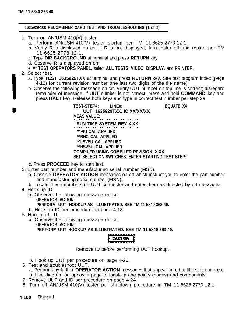
1635929-100 RECOMBINER CARD TEST AND TROUBLESHOOTING (1 of 2)
1. Turn on AN/USM-410(V) tester.a. Perform AN/USM-410(V) tester startup per TM 11-6625-2773-12-1.b. Verify R is displayed on crt. If R is not displayed, turn tester off and restart per TM
11-6625-2773-12-1.c. Type DIR BACKGROUND at terminal and press RETURN key.d. Observe R is displayed on crt.e. At TEST OPERATORS PANEL, select ALL TESTS, VIDEO DISPLAY, and PRINTER.
2. Select test.a. Type TEST 1635929TXX at terminal and press RETURN key. See test program index (page
4-12) for current revision number (the last two digits of the file name).b. Observe the following message on crt. Verify UUT number on top line is correct; disregard
remainder of message. If UUT number is not correct, press and hold COMMAND key andpress HALT key. Release both keys and type in correct test number per step 2a.
TEST-STEP#: LINE#: EQUATE XXUUT: 1635929TXX. IC XX/XX/XX
MEAS VALUE:. . . . . . . . . . . . . . . . . . . . . . . . . . . . . . . . . . . . . . .- RUN TIME SYSTEM REV X.XX -. . . . . . . . . . . . . . . . . . . . . . . . . . . . . . . . . . . . . . .
**PIU CAL APPLIED**BNC CAL APPLIED**LSVSU CAL APPLIED**HSVSU CAL APPLIED
COMPILED USING COMPILER REVISION: X.XXSET SELECTlON SWITCHES. ENTER STARTING TEST STEP:
c. Press PROCEED key to start test.3. Enter part number and manufacturing serial number (MSN).
a. Observe OPERATOR ACTION messages on crt which instruct you to enter the part numberand manufacturing serial number (MSN).
b. Locate these numbers on UUT connector and enter them as directed by crt messages.4. Hook up ID.
a. Observe the following message on crt.OPERATOR ACTIONPERFORM UUT HOOKUP AS ILLUSTRATED. SEE TM 11-5840-363-40.
b. Hook up ID per procedure on page 4-18.5. Hook up UUT.
a. Observe the following message on crt.OPERATOR ACTIONPERFORM UUT HOOKUP AS ILLUSTRATED. SEE TM 11-5840-363-40.
Remove ID before performing UUT hookup.
b. Hook up UUT per procedure on page 4-20.6. Test and troubleshoot UUT.
a. Perform any further OPERATOR ACTION messages that appear on crt until test is complete.b. Use diagram on opposite page to locate probe points (nodes) and components.
7. Remove UUT and ID per procedure on page 4-24.8. Turn off AN/USM-410(V) tester per shutdown procedure in TM 11-6625-2773-12-1.
4-100 Change 1
TM 11-5840-363-40

TM 11-5840-363-40
1635929-100 RECOMBINER CARD TEST AND TROUBLESHOOTING, {2 of 2)
4-101

1635930-100 SIGNATURE GENERATOR CARD TEST AND TROUBLESHOOTING (1 of 2)
1. Turn on AN/USM-410(V) tester.a. Perform AN/USM-410(V) tester startup per TM 11-6625-2773-12-1.b. Verify R is. displayed on crt. If R is not displayed, turn tester off and restart per TM.-
11-6625-2773-12-1.c. Type DIR BACKGROUND at terminal and press RETURN key.d. Observe R is displayed on crt.e. At TEST OPERATORS PANEL, select ALL TESTS, VIDEO DISPLAY, and PRINTER.
2. Select test.a.
b.
c.
Type TEST 1635930TXX at terminal and press RETURN key. See test program index (page4-12) for current revision number (the last two digits of the file name).Observe the following message on crt. Verify UUT number on top line is correct; disregardremainder of message, If UUT number is not correct, press and hold COMMAND key andpress HALT key. Release both keys and type in correct test number per step 2a.
TEST-STEP#: LINE#: EQUATE XXUUT: 1635930TXX. IC XX/XX/XX
MEAS VALUE:. . . . . . . . . . . . . . . . . . . . . . . . . . . . . . . . . . . . . . .- RUN TIME SYSTEM REV X.XX ----------------------------------------
**PIU CAL APPLIED**BNC CAL APPLIED**LSVSU CAL APPLIED**HSVSU CAL APPLIED
COMPILED USING COMPILER REVISION: X.XXSET SELECTOR SWITCHES. ENTER STARTING TEST STEP:
Press PROCEED key to start test.3. Enter part number and manufacturing serial number (MSN).
a. Observe OPERATOR ACTION messages on crt which instruct you to enter the part numberand manufacturing serial number (MSN).
b. Locate these numbers on UUT connector and enter them as directed by crt messages.4. Hook up ID.
a. Observe the following message on crt.OPERATOR ACTIONPERFORM ID HOOKUP AS ILLUSTRATED. SEE TM 11-5840-363-40.
b. Hook up ID per procedure on page 4-18.5. Hook up UUT.
a. Observe the following message on crt.OPERATOR ACTIONPERFORM UUT HOOKUP AS ILLUSTRATED. SEE TM 11-5840-363-40.
Remove ID before performing UUT hookup.
b. Hook up UUT per procedure on page 4-20.6. Test and troubleshoot UUT.
a. Perform any further OPERATOR ACTION messages that appear on crt until test is complete.b. Use diagram on opposite page to locate probe points (nodes) and components.
7. Remove UUT and ID per procedure on page 4-24.8. Turn off AN/USM-410(V) tester per shutdown procedure in TM 11-6625-2773-12-1.
4-102 Change 1
TM 11-5840-363-40

TM 11-5840-363-40
4-103
1635930-100 SIGNATURE GENERATOR CARD TEST AND TROUBLESHOOTING (2 of 2)

TM 11-5840-363-40
1635931-100 TRI-STATE MULTIPLEXER CARD TEST AND TROUBLESHOOTING (1 of 2)
1. Turn on AN/USM-410(V) tester.a. Perform AN/USM-410(V) tester startup per TM 11-6625-2773-12-1.b. Verify R is displayed on crt. If R is not displayed, turn tester off and restart per TM
11-6625-2773-12-1.c. Type DIR BACKGROUND at terminal and press RETURN key.d. Observe R is displayed on crt.e. At TEST OPERATORS PANEL, select ALL TESTS, VIDEO DISPLAY, and PRINTER.
2. Select test.a. Type TEST 1635931TXX at terminal and press RETURN key. See test program index (page
4-12) for current revision number (the last two digits of the file name).b. Observe the following message on crt. Verify UUT number on top line is correct; disregard
remainder of message. If UUT number is not correct, press and hold COMMAND key andpress HALT key. Release both keys and type in correct test number per step 2a.
TEST-STEP#: LINE#: EQUATE XXUUT: 1635931TXX. IC XX/XX/XX
MEAS VALUE:. . . . . . . . . . . . . . . . . . . . . . . . . . . . . . . . . . . . . . .- RUN TIME SYSTEM REV X.XX -.. . . . . . . . . . . . . . . . . . . . . . . . . . . . . . . . . . . . . . .
**PIU CAL APPLIED**BNC CAL APPLIED**LSVSU CAL APPLIED**HSVSU CAL APPLIED
COMPILED USING COMPILER REVISION: X.XXSET SELECTOR SWITCHES. ENTER STARTING TEST STEP:
c. Press PROCEED key to start test.3. Enter part number and manufacturing serial number (MSN).
a. Observe OPERATOR ACTION messages on crt which instruct you to enter the part numberand manufacturing serial number (MSN).
b. Locate these numbers on UUT connector and enter them as directed by crt messages.4. Hook up ID.
a. Observe the following message on crt.OPERATOR ACTIONPERFORM ID HOOKUP AS ILLUSTRATED. SEE TM 11-5840-363-40.
b. Hook up ID per procedure on page 4-18.5. Hook up UUT.
a. Observe the following message on crt.OPERATOR ACTIONPERFORM UUT HOOKUP AS ILLUSTRATED. SEE TM 11-5840-363-40.
Remove ID before performing UUT hookup.
b. Hook up UUT per procedure on page 4-20.6. Test and troubleshoot UUT.
a. Perform any further OPERATOR ACTION messages that appear on crt until test is complete.b. Use diagram on opposite page to locate probe points (nodes) and components.
7. Remove UUT and ID per procedure on page 4-24.8. Turn off AN/USM-410(V) tester per shutdown procedure in TM 11-6625-2773-12-1.
4-104 Change 1

TM 11-5840-363-40
4-105
1635931-100 TRI-STATE MULTIPLEXER CARD TEST AND TROUBLESHOOTING (2 of 2)

TM 11-5840-363-40
1635932-100 RECEIVER GAIN CONTROL CARD TEST AND TROUBLESHOOTING (1 of 2)
1. Turn on AN/USM-410(V) tester.a. Perform AN/USM-410(V) tester startup per TM 11-6625-2773-12-1.b. Verify R is displayed on crt. If R is not displayed, turn tester off and restart per TM
11-6625-2773-12-1.c. Type DIR BACKGROUND at terminal and press RETURN key.d. Observe R is displayed on crt.a. At TEST OPERATORS PANEL, select ALL TESTS, VIDEO DISPLAY, and PRINTER.
2. Select test. a. Type TEST 1635932TXX at terminal and press RETURN key. See test program index (page
4-12) for current revision number (the last two digits of the file name).b. Observe the following message on crt. Verify UUT number on top line is correct; disregard
remainder of message. If UUT number is not correct, press and hold COMMAND key andpress HALT key. Release both keys and type in correct test number per step 2a.
TEST-STEP#: LINE#: EQUATE XXUUT: 1635932TXX. IC XX/XX/XX
MEAS VALUE:. . . . . . . . . . . . . . . . . . . . . . . . . . . . . . . . . . . . . . .- RUN TIME SYSTEM REV X.XX -.. . . . . . . . . . . . . . . . . . . . . . . . . . . . . . . . . . . . . .
**PIU CAL APPLIED**BNC CAL APPLIED**LSVSU CAL APPLIED**HSVSU CAL APPLIED
COMPILED USING COMPILER REVISION: X.XXSET SELECTOR SWITCHES. ENTER STARTING TEST STEP:
c. Press PROCEED key to start test.3. Enter part number and manufacturing serial number (MSN).
a. Observe OPERATOR ACTION messages on crt which instruct you to enter the part numberand manufacturing serial number (MSN).
b. Locate these numbers on UUT connector and enter them as directed by crt messages.4. Hook up ID.
a. Observe the following message on crt.OPERATOR ACTIONPERFORM ID HOOKUP AS ILLUSTRATED. SEE TM 11-5840-363-40.
b. Hook up ID per procedure on page 4-18.5. Hook up UUT.
a. Observe the following message on crt.OPERATOR ACTIONPERFORM UUT HOOKUP AS ILLUSTRATED. SEE TM 11-5840-363-40.
Remove ID before performing UUT hookup.
b. Hook up UUT per procedure on page 4-20.6. Test and troubleshoot UUT.
a. Perform any further OPERATOR ACTION messages that appear on crt until test is complete.b. Use diagram on opposite page to locate probe points (nodes) and components.
7. Remove UUT and ID per procedure on page 4-24.8. Turn off AN/USM-410(V) tester per shutdown procedure in TM 11-6625-2773-12-1.
4-106 Change 1

TM 11-5840-363-40
4-107
1635932-100 RECEIVER GAIN CONTROL CARD TEST AND TROUBLESHOOTING (2 of 2)

TM 11-5840-363-40
1635933-100 RAM ADDRESS GENERATOR CARD TEST AND TROUBLESHOOTING (1 of 2)
1. Turn on AN/USM-410(V) tester.a. Perform AN/USM-410(V) tester startup per TM 11-6625-2773-12-1.b. Verify R is displayed on crt. If R is not displayed, turn tester off and restart per TM
11-6625-2773-12-1.c. Type DIR BACKGROUND at terminal and press RETURN key.d. Observe R is displayed on crt.e. At TEST OPERATORS PANEL, select ALL TESTS, VIDEO DISPLAY, and PRINTER.
2. Select test.a. Type TEST 1635933TXX at terminal and press RETURN key. See test program index (page
4-12) for current revision number (the last two digits of the file name).b. Observe the following message on crt. Verify UUT number on top line is correct; disregard
remainder of message. If UUT number is not correct, press and hold COMMAND key andpress HALT key. Release both keys and type in correct test number per step 2a.
TEST-STEP#: LINE#: EQUATE XXUUT: 1635933TXX. IC XX/XX/XX
MEAS VALUE:. . . . . . . . . . . . . . . . . . . . . . . . . . . . . . . . . . . . . . .– RUN TIME SYSTEM REV X.XX -. . . . . . . . . . . . . . . . . . . . . . . . . . . . . . . . . . . . . . .
**PIU CAL APPLIED**BNC CAL APPLIED**LSVSU CAL APPLIED**HSVSU CAL APPLIED
COMPILED USING COMPILER REVISION: X.XXSET SELECTOR SWITCHES. ENTER STARTING TEST STEP:
c. Press PROCEED key to start test.3. Enter part number and manufacturing serial number (MSN).
a. Observe OPERATOR ACTION messages on crt which instruct you to enter the part numberand manufacturing serial number (MSN).
b. Locate these numbers on UUT connector and enter them as directed by crt messages.4. Hook up ID.
a. Observe the following message on crt.OPERATOR ACTIONPERFORM ID HOOKUP AS ILLUSTRATED. SEE TM 11-5840-363-40.
b. Hook up ID per procedure on page 4-18.5. Hook up UUT.
a. Observe the following message on crt.OPERATOR ACTIONPERFORM UUT HOOKUP AS ILLUSTRATED. SEE TM 11-5840-363-40.
Remove ID before performing UUT hookup.
b. Hook up UUT per procedure on page 4-20.6. Test and troubleshoot UUT.
a. Perform any further OPERATOR ACTION messages that appear on crt until test is complete.b. Use diagram on opposite page to locate probe points (nodes) and components.
7. Remove UUT and ID per procedure on page 4-24.8. Turn off AN/USM-410(V) tester per shutdown procedure in TM 11-6625-2773-12-1.
4-108 Change 1

TM 11-5840-363-40
4-109
1635933-100 RAM ADDRESS GENERATOR CARD TEST AND TROUBLESHOOTING (2 of 2)

TM 11-5840-363-40
1635935-100 DIFFERENTIAL DRIVER/RECEIVER CARD TEST AND TROUBLESHOOTING (1 of 2)
1. Turn on AN/USM-410(V) tester.a. Perform AN/USM-410(V) tester startup per TM 11-6625-2773-12-1.b. Verify R is displayed on crt. If R is not displayed, turn tester off and restart per TM
11-6625-2773-12-1.c. Type DIR BACKGROUND at terminal and press RETURN key.d. Observe R is displayed on crt.e. At TEST OPERATORS PANEL, select ALL TESTS, VIDEO DISPLAY, and PRINTER.
2. Select test.a. Type TEST 1635935TXX at terminal and press RETURN key. See test program index (page
4-12) for current revision number (the last two digits of the file name).b. Observe the following message on crt. Verify UUT number on top line is correct; disregard
remainder of message. If UUT number is not correct, press and hold COMMAND key andpress HALT key. Release both keys and type in correct test number per step 2a.
TEST-STEP#: LINE#: EQUATE XXUUT: 1635935TXX. IC XX/XX/XX
MEAS VALUE:. . . . . . . . . . . . . . . . . . . . . . . . . . . . . . . . . . . . . . .- RUN TIME SYSTEM REV X.XX -. . . . . . . . . . . . . . . . . . . . . . . . . . . . . . . . . . . . . . .
**PIU CAL APPLIED**BNC CAL APPLIED**LSVSU CAL APPLIED**HSVSU CAL APPLIED
COMPILED USING COMPILER REVISION: X.XXSET SELECTOR SWITCHES. ENTER STARTING TEST STEP:
c. Press PROCEED key to start test.3. Enter part number and manufacturing serial number (MSN).
a. Observe OPERATOR ACTION messages on crt which instruct you to enter the part numberand manufacturing serial number (MSN).
b. Locate these numbers on UUT connector and enter them as directed by crt messages.4. Hook up ID.
a. Observe the following message on crt.OPERATOR ACTIONPERFORM ID HOOKUP AS ILLUSTRATED. SEE TM 11-5840-363-40.
b. Hook up ID per procedure on page 4-18.5. Hook up UUT.
a. Observe the following message on crt.OPERATOR ACTIONPERFORM UUT HOOKUP AS ILLUSTRATED. SEE TM 11-5840-363-40.
Remove ID before performing UUT hookup.
b. Hook up UUT per procedure on page 4-20.6. Test and troubleshoot UUT.
a. Perform any further OPERATOR ACTION messages that appear on crt until test is complete b. Use diagram on opposite page to locate probe points (nodes) and components.
7. Remove UUT and ID per procedure on page 4-24.8. Turn off AN/USM-410(V) tester per shutdown procedure in TM 11-6625-2773-12-1.
4-110 Change 1

TM 11-5840-363-40
4-111
1635935-100 DIFFERENTIAL DRIVER/RECEIVER CARD TEST AND TROUBLESHOOTING (2 of 2)

11635936-100 VIDEO INPUT MULTIPLEX CARD TEST AND TROUBLESHOOTING (1 of 2)
1. Turn on AN/USM-410(V) tester.a. Perform AN/USM-410(V) tester startup per TM 11-6625-2773-12-1.b. Verify R is displayed on crt. If R is not displayed, turn tester off and restart per TM
11-6625-2773-12-1.
2.
c. Type DIR BACKGROUND at terminal and press RETURN key.d. Observe R is displayed on crt.e. At TEST OPERATORS PANEL, select ALL TESTS, VIDEO DISPLAY, and PRINTER.Select test.a. Type TEST 1635936TXX at terminal and press RETURN key. See test program index (page
4-12) for current revision number (the last two digits of the file name).b. Observe the following message on crt. Verify UUT number on top line is correct; disregard
remainder of message. If UUT number is not correct, press and hold COMMAND key andpress HALT key. Release both keys and type in correct test number per step 2a.
TEST-STEP#: LINE#: EQUATE XXUUT: 1635936TXX. IC XX/XX/XX
MEAS VALUE:. . . . . . . . . . . . . . . . . . . . . . . . . . . . . . . . . . . . . . .- RUN TIME SYSTEM REV X.XX -. . . . . . . . . . . . . . . . . . . . . . . . . . . . . . . . . . . . . . .
**PIU CAL APPLIED**BNC CAL APPLIED**LSVSU CAL APPLIED**HSVSU CAL APPLIED
COMPILED USING COMPILER REVISION: X.XXSET SELECTOR SWITCHES. ENTER STARTING TEST STEP:
c. Press PROCEED key to start test.3. Enter part number and manufacturing serial number (MSN).
a. Observe OPERATOR ACTION messages on crt which instruct you to enter the part numberand manufacturing serial number (MSN).
b. Locate these numbers on UUT connector and enter them as directed by crt messages.4. Hook up ID.
a. Observe the following message on crt.OPERATOR ACTIONPERFORM ID HOOKUP AS ILLUSTRATED. SEE TM 11-5840-363-40.
b. Hook up ID per procedure on page 4-18.5. Hook up UUT.
a. Observe the following message on crt.OPERATOR ACTIONPERFORM UUT HOOKUP AS ILLUSTRATED. SEE TM 11-5840-363-40.
Remove ID before performing UUT hookup.
b. Hook up UUT per procedure on page 4-20.6. Test and troubleshoot UUT.
a. Perform any further OPERATOR ACTION messages that appear on crt until test is complete.b. Use diagram on opposite page to locate probe points (nodes) and components.
7. Remove UUT and ID per procedure on page 4-24.8. Turn off AN/USM-410(V) tester per shutdown procedure in TM 11-6625-2773-12-1.
4-112 Change 1
TM 11-5840-363-40

TM 11-5840-363-40
4-113
1635936-100 VIDEO INPUT MULTIPLEX CARD TEST AND TROUBLESHOOTING (2 of 2)

TM 11-5840-363-40
1635937-100 POWER SUPPLY BITE/BUFFER CARD TEST AND TROUBLESHOOTING (1 of 2)
1. Turn on AN/USM-410(V) tester.a. Perform AN/USM-410(V) tester startup per TM 11-6625-2773-12-1.b. Verify R is displayed on crt. If R is not displayed, turn tester off and restart per TM
11-6625-2773-12-1.c. Type DIR BACKGROUND at terminal and press RETURN key.d. Observe R is displayed on crt.e. At TEST OPERATORS PANEL, select ALL TESTS, VIDEO DISPLAY, and PRINTER.
2. Select test.a. Type TEST 1635937TXX at terminal and press RETURN key. See test program index (page
4-12) for current revision number (the last two digits of the file name).b. Observe the following message on crt. Verify UUT number on top line is correct; disregard
remainder of message. If UUT number is not correct, press and hold COMMAND key andpress HALT key. Release both keys and type in correct test number per step 2a.
TEST-STEP#: LINE#: EQUATE XXUUT: 1635937TXX. IC XX/XX/XX
MEAS VALUE:---------------------------------------- RUN TIME SYSTEM REV X.XX ----------------------------------------
**PIU CAL APPLIED**BNC CAL APPLIED**LSVSU CAL APPLIED**HSVSU CAL APPLIED
COMPILED USING COMPILER REVISION: X.XXSET SELECTOR SWITCHES. ENTER STARTING TEST STEP:
c. Press PROCEED key to start test.3. Enter part number and manufacturing serial number (MSN).
a. Observe OPERATOR ACTION messages on crt which instruct you to enter the part numberand manufacturing serial number (MSN).
b. Locate these numbers on UUT connector and enter them as directed by crt messages.4. Hook up ID.
a. Observe the following message on crt.OPERATOR ACTIONPERFORM ID HOOKUP AS ILLUSTRATED. SEE TM 11-5840-363-40.
b. Hook up ID per procedure on page 4-18.5. Hook up UUT.
a. Observe the following message on crt.OPERATOR ACTIONPERFORM UUT HOOKUP AS ILLUSTRATED. SEE TM 11-5840-363-40.
Remove ID before performing UUT hookup.
b. Hook up UUT per procedure on page 4-20.6. Test and troubleshoot UUT.
a. Perform any further OPERATOR ACTION messages that appear on crt until test is complete.b. Use diagram on opposite page to locate probe points (nodes) and components.
7. Remove UUT and ID per procedure on page 4-24.8. Turn off AN/USM-410(V) tester per shutdown procedure in TM 11-6625-2773-12-1.
4-114 Change 1

TM 11-5840-363-40
4-115
1635937-100 POWER SUPPLY BITE/BUFFER CARD TEST AND TROUBLESHOOTING (2 of 2)

TM 11-5840-363-40
1635939-100 GENERAL PURPOSE REGISTER CARD TEST AND TROUBLESHOOTING (1 of 2)
1. Turn on AN/USM-410(V) tester.a. Perform AN/USM-410(V) tester startup per TM 11-6625-2773-12-1.b. Verify R is displayed on crt. If R is not displayed, turn tester off and restart per TM
11-6625-2773-12-1.
2.
3.
4.
5.
c. Type DIR BACKGROUND at terminal and press RETURN key.d. Observe R is displayed on crt.e. At TEST OPERATORS PANEL, select ALL TESTS, VIDEO DISPLAY, and PRINTER.Select test.a. Type TEST 1635939TXX at terminal and press RETURN key. See test program index (page
4-12) for current revision number (the last two digits of the file name).b. Observe the following message on crt. Verify UUT number on top line is correct; disregard
remainder of message. If UUT number is not correct, press and hold COMMAND key andpress HALT key. Release both keys and type in correct test number per step 2a.
TEST-STEP#: LINE#: EQUATE XXUUT: 1635939TXX. IC XX/XX/XX
MEAS VALUE:. . . . . . . . . . . . . . . . . . . . . . . . . . . . . . . . . . . . . . .– RUN TIME SYSTEM REV X.XX -. . . . . . . . . . . . . . . . . . . . . . . . . . . . . . . . . . . . . . . .
**PIU CAL APPLIED**BNC CAL APPLIED**LSVSU CAL APPLIED**HSVSU CAL APPLIED
COMPILED USING COMPILER REVISION: X.XXSET SELECTOR SWITCHES. ENTER STARTING TEST STEP:
c. Press PROCEED key to start test.Enter part number and manufacturing serial number (MSN).a. Observe OPERATOR ACTION messages on crt which instruct you to enter the part number
and manufacturing serial number (MSN).b. Locate these numbers on UUT connector and enter them as directed by crt messages.Hook up ID.a. Observe the following message on crt.
OPERATOR ACTIONPERFORM ID HOOKUP AS ILLUSTRATED. SEE TM 11-5840-363-40.
b. Hook up ID per procedure on page 4-18.Hook up UUT.a. Observe the following message on crt.
OPERATOR ACTIONPERFORM UUT HOOKUP AS ILLUSTRATED. SEE TM 11-5840-363-40.
Remove ID before performing UUT hookup.
b. Hook up UUT per procedure on page 4-20.6. Test and troubleshoot UUT.
a. Perform any further OPERATOR ACTION messages that appear on crt until test is complete. b. Use diagram on opposite page to locate probe points (nodes) and components.
7. Remove UUT and ID per procedure on page 4-24.8. Turn off AN/USM-410(V) tester per shutdown procedure in TM 11-6625-2773-12-1.
4-116 Change 1

TM 11-5840-363-40
4-117
1635939-100 GENERAL PURPOSE REGISTER CARD TEST AND TROUBLESHOOTING (2 OF 2)

1635940-100 GENERAL PURPOSE GATE CARD TEST AND TROUBLESHOOTING (1 of 2)
1. Turn on AN/USM-410(V) tester.a. Perform AN/USM-410(V) tester startup per TM 11-6625-2773-12-1.b. Verify R is displayed on crt. If R is not displayed, turn tester off and restart per TM
11-6625-2773-12-1.c. Type DIR BACKGROUND at terminal and press RETURN key.d. Observe R is displayed on crt.e. At TEST OPERATORS PANEL, select ALL TESTS, VIDEO DISPLAY, and PRINTER.
2. Select test.a. Type TEST 1635940TXX at terminal and press RETURN key. See test program index (page
4-12) for current revision number (the last two digits of the file name).b. Observe the following message on crt. Verify UUT number on top line is correct; disregard
remainder of message. If UUT number is not correct, press and hold COMMAND key andpress HALT key. Release both keys and type in correct test number per step 2a.
TEST-STEP#: LINE#: EQUATE XXUUT: 1635940TXX. IC XX/XX/XX
MEAS VALUE:---------------------------------------- RUN TIME SYSTEM REV X.XX -. . . . . . . . . . . . . . . . .... . . . . . . . . . . . . . . . . . . . . . . . . . . . . .
**PIU CAL APPLIED**BNC CAL APPLIED**LSVSU CAL APPLIED** HSVSU CAL APPLIED
COMPILED USING COMPILER REVISION: X.XXSET SELECTOR SWITCHES. ENTER STARTING TEST STEP:
c. Press PROCEED key to start test.3. Enter part number and manufacturing serial number (MSN).
a. Observe OPERATOR ACTION messages on crt which instruct you to enter the part numberand manufacturing serial number (MSN).
b. Locate these numbers on UUT connector and enter them as directed by crt messages.4. Hook up ID.
a. Observe the following message on crt.OPERATOR ACTIONPERFORM ID HOOKUP AS ILLUSTRATED. SEE TM 11-5840-363-40.
b. Hook up ID per procedure on page 4-18.5. Hook up UUT.
a. Observe the following message on crt.OPERATOR ACTIONPERFORM UUT HOOKUP AS ILLUSTRATED. SEE TM 11-5840-363-40.
Remove ID before performing UUT hookup.
b. Hook up UUT per procedure on page 4-20.6. Test and troubleshoot UUT.
a. Perform any further OPERATOR ACTION messages that appear on crt until test is complete. b. Use diagram on opposite page to locate probe points (nodes) and components.
7. Remove UUT and ID per procedure on page 4-24.8. Turn off AN/USM-410(V) tester per shutdown procedure in TM 11-6625-2773-12-1.
4-118 Change 1
TM 11-5840-363-40
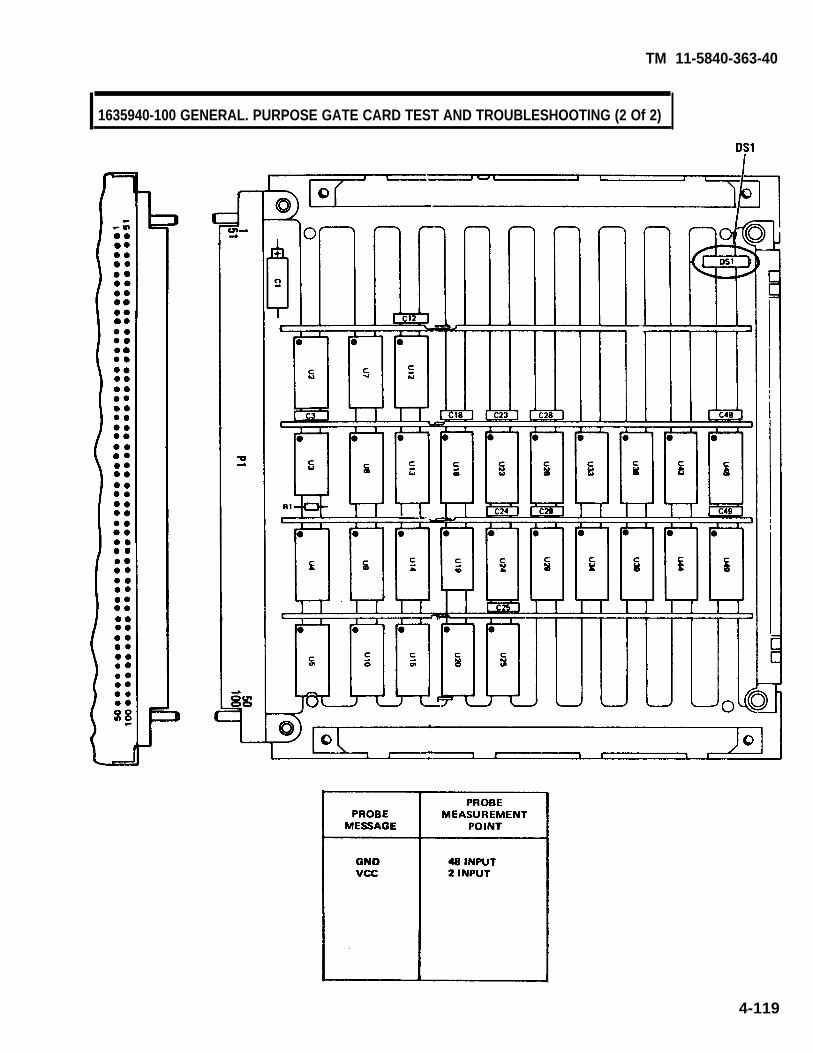
TM 11-5840-363-40
1635940-100 GENERAL. PURPOSE GATE CARD TEST AND TROUBLESHOOTING (2 Of 2)
4-119

TM 11-5840-363-40
1635941-100 TIMING DECODER NO. 2 CARD TEST AND TROUBLESHOOTING (1 of 2)
1. Turn on AN/USM-410(V) tester.a. Perform AN/USM-410(V) tester startup per TM 11-6625-2773-12-1.b. Verify R is displayed on crt. If R is not displayed, turn tester off and restart per TM
11-6625-2773-12-1.c. Type DIR BACKGROUND at terminal and press RETURN key.d. Observe R is displayed on crt.e. At TEST OPERATORS PANEL, select ALL TESTS, VIDEO DISPLAY, and PRINTER.
2. Select test.a. Type TEST 1635941TXX at terminal and press RETURN key. See test program index (page
4-12) for current revision number (the last two digits of the file name).b. Observe the following message on crt. Verify UUT number on top line is correct; disregard
remainder of message. If UUT number is not correct, press and hold COMMAND key andpress HALT key. Release both keys and type in correct test number per step 2a.
TEST-STEP#: LINE#: EQUATE XXUUT: 1635941TXX. IC XX/XX/XX
MEAS VALUE:. . . . . . . . . . . . . . . . . . . . . . . . . . . . . . . . . . . . . . .- RUN TIME SYSTEM REV X.XX -. . . . . . . . . . . . . . . . . . . . . . . . . . . . . . . . . . . . . . .
**PIU CAL APPLIED**BNC CAL APPLIED**LSVSU CAL APPLIED**HSVSU CAL APPLIED
COMPILED USING COMPILER REVISION: X.XXSET SELECTOR SWITCHES. ENTER STARTING TEST STEP:
c. Press PROCEED key to start test.3. Enter part number and manufacturing serial number (MSN).
a. Observe OPERATOR ACTION messages on crt which instruct you to enter the part numberand manufacturing serial number (MSN).
b. Locate these numbers on UUT connector and enter them as directed by crt messages.4. Hook up ID.
a. Observe the following message on crt.OPERATOR ACTIONPERFORM ID HOOKUP AS ILLUSTRATED. SEE TM 11-5840-363-40.
b. Hook up ID per procedure on page 4-18.6. Hook up UUT.
a. Observe the following message on crt.OPERATOR ACTIONPERFORM UUT HOOKUP AS ILLUSTRATED. SEE TM 11-5840-363-40.
Remove ID before performing UUT hookup.
b. Hook up UUT per procedure on page 4-20.6. Test and troubleshoot UUT.
a. Perform any further OPERATOR ACTION messages that appear on crt until test is complete. b. Use diagram on opposite page to locate probe points (nodes) and components.
7. Remove UUT and ID per procedure on page 4-24.8. Turn off AN/USM-410(V) tester per shutdown procedure in TM 11-6625-2773-12-1.
4-120 Change 1

TM 11-5840-363-40
1635941-100 TIMING DECODER NO. 2 CARD TEST AND TROUBLESHOOTING (2 of 2)
4-121

TM 11-5840-363-40
1635942-100 A/D CONVERTER CARD TEST AND TROUBLESHOOTING (1 of 2)
1. Turn on AN/USM-410(V) tester.a. Perform AN/USM-410(V) tester startup per TM 11-6625-2773-12-1.b. verify R is displayed on crt. If R is not displayed, turn tester off and restart per TM
11-6625-2773-12-1.c. Type DIR BACKGROUND at terminal and press RETURN key.d. Observe R is displayed on crt.e. At TEST OPERATORS PANEL, select ALL TESTS, VIDEO DISPLAY, and PRlNTER.
2. Select test.a.
b.
c.
Type TEST 1635942TXX at terminal and press RETURN key. See test program index (page4-12) for current revision number (the last two digits of the file name).Observe the following message on crt. Verify UUT number on top line is correct; disregardremainder of message. If UUT number is not correct, press and hold COMMAND key andpress HALT key. Release both keys and type in correct test number per step 2a.
TEST-STEP#: LINE#: EQUATE XXUUT: 1635942TXX. IC XX/XX/XX
MEAS VALUE:- - - - - - - - - - - ------ -- - - - - - - - - - - - - - - - -- RUN TIME SYSTEM REV X.XX ----------------------------------------
**PIU CAL APPLIED**BNC CAL APPLIED**LSVSU CAL APPLlED**HSVSE CAL APPLIED
COMPILED USING COMPILER REVISION: X.XXSET SELECTOR SWITCHES. ENTER STARTING TEST STEP:
Press PROCEED key to start test.3. Enter path number and manufacturing serial number (MSN).
a. Observe OPERATOR ACTION messages on crt which instruct you to enter the part numberand manufacturing serial number (MSN).
b. Locate these numbers on UUT connector and enter them as directed by crt messages.
4-122 Change 1

635942-100 A/D CONVERTER CARD TEST AND TROUBLESHOOTING (2 of 2)
4. Hook up ID.a. Observe the following message on crt.
OPERATOR ACTIONPERFORM ID HOOKUP AS ILLUSTRATED. SEE TM 11-5840-363-40.
b. Hook up ID per procedure on page 4-18.5. Hook up UUT.
a. Observe the following message on crt.OPERATOR ACTIONPERFORM UUT HOOKUP AS ILLUSTRATED. SEE TM 11-5840-363-40.
Remove ID before performing UUT hookup.
b. Hook up UUT per procedure on page 4-20.6. Test and troubleshoot UUT.
a. Perform any further OPERATOR ACTION messages that appear on crt until test is complete.b. Use diagram on page FO-12 to locate probe points (nodes) and components.
7. Remove UUT and ID per procedure on page 4-24.8. Turn off AN/USM-410(V) tester per shutdown procedure in TM 11-6625-2773-12-1.
4-123
TM 11-5840-363-40

TM 11-5840-363-40
1635944-100 OR -101 8-MHz SAMPLE AND HOLD CARD TEST AND TROUBLESHOOTING (1 of 2)
1. Turn on AN/USM-410(V) tester.a. Perform AN/USM-410(V) tester startup per TM 11-6625-2773-12-1.b. Verify R is displayed on crt. If R is not displayed, turn tester off and restart per TM
11-6625-2773-12-1.c. Type DIR BACKGROUND at terminal and press RETURN key.d. Observe R is displayed on crt.e. At TEST OPERATORS PANEL, select ALL TESTS, VIDEO DISPLAY, and PRINTER.
2. Select test.a. Type TEST 1635944TXX at terminal and press RETURN key. See test program index (page
4-12) for current revision number (the last two digits of the file name).b. Observe the following message on crt. Verify UUT number on top line is correct; disregard
remainder of message. If UUT number is not correct, press and hold COMMAND key andpress HALT key. Release both keys and type in correct test number per step 2a.
TEST-STEP#: LINE#: EQUATE XXUUT: 1635944TXX. IC XX/XX/XX
MEAS VALUE:---------------------------------------- RUN TIME SYSTEM REV X.XX ---- - - - - - - - - - - - - - - - - - - - - - - - - - - - - - - - - - - - - - -
**PIU CAL APPLIED**BNC CAL APPLIED**LSVSU CAL APPLIED**HSVSU CAL APPLIED
COMPILED USING COMPILER REVISION: X.XXSET SELECTOR SWITCHES. ENTER STARTING TEST STEP:
c. Press PROCEED key to start test.3. Enter part number and manufacturing serial number (MSN).
a. Observe OPERATOR ACTION messages on crt which instruct you to enter the part numberand manufacturing serial number (MSN).
b. Locate these numbers on UUT connector and enter them as directed by crt messages.4. Hook up ID.
a. Observe the following message on crt.OPERATOR ACTIONPERFORM ID HOOKUP AS ILLUSTRATED. SEE TM 11-5840-363-40.
b. Hook up ID per procedure on page 4-18.5. Hook up UUT.
a. Observe the following message on crt.OPERATOR ACTIONPERFORM UUT HOOKUP AS ILLUSTRATED. SEE TM 11-5840-363-40.
Remove ID before performing UUT hookup.
b. Hook up UUT per procedure on page 4-20.6. Test and troubleshoot UUT.
a. Perform any further OPERATOR ACTION messages that appear on crt until test is complete.b. Use diagram on opposite page to locate probe points (nodes) and components.
7. Remove UUT and ID per procedure on page 4-24.8. Turn off AN/USM-410(V) tester per shutdown procedure in TM 11-6625-2773-12-1.
4-124 Change 1
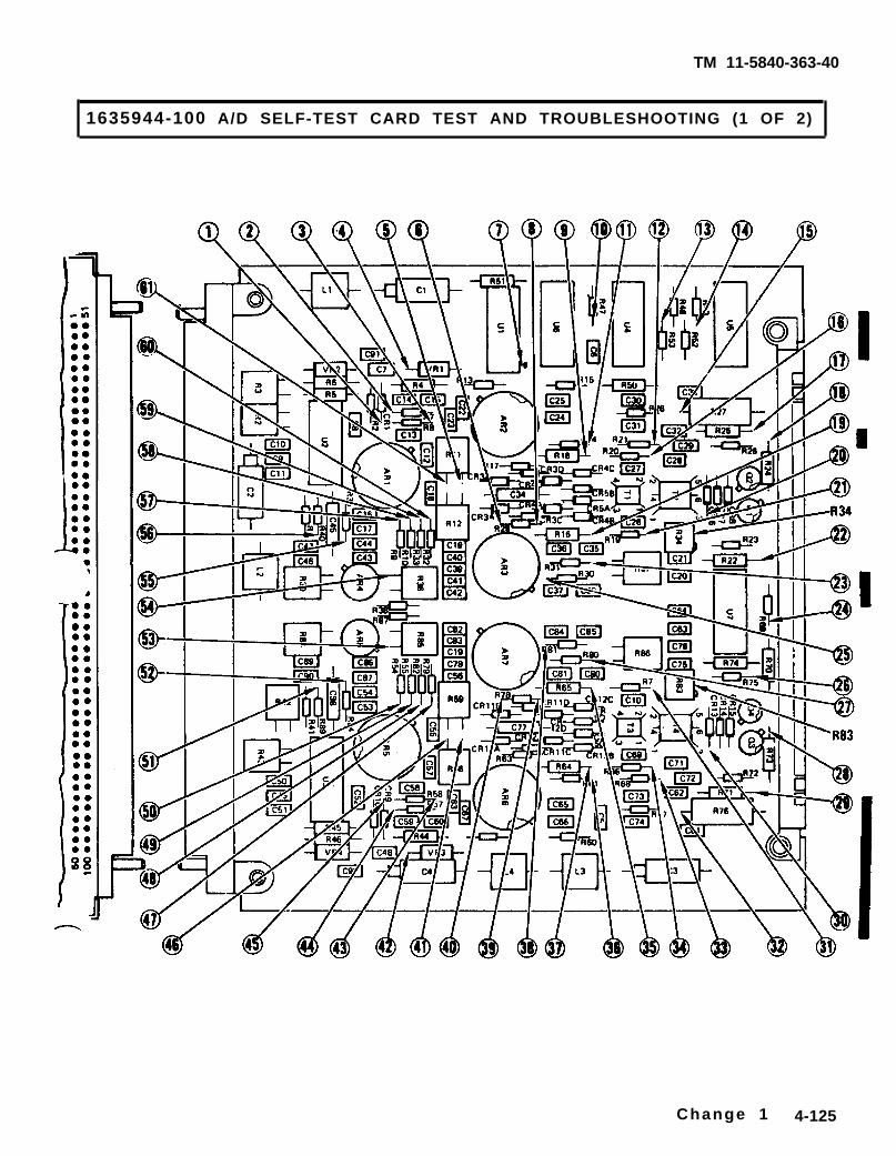
TM 11-5840-363-40
Change 1 4-125
1635944-100 A/D SELF-TEST CARD TEST AND TROUBLESHOOTING (1 OF 2)
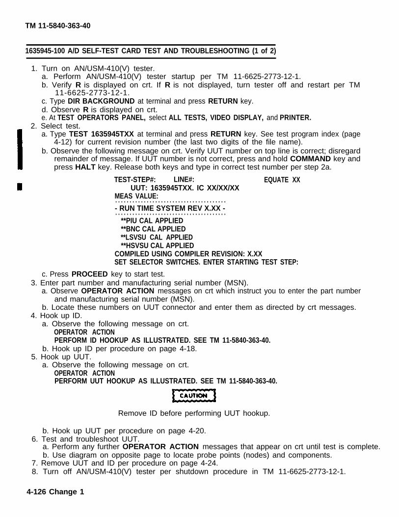
TM 11-5840-363-40
1635945-100 A/D SELF-TEST CARD TEST AND TROUBLESHOOTING (1 of 2)
1. Turn on AN/USM-410(V) tester.a. Perform AN/USM-410(V) tester startup per TM 11-6625-2773-12-1.b. Verify R is displayed on crt. If R is not displayed, turn tester off and restart per TM
11-6625-2773-12-1.c. Type DIR BACKGROUND at terminal and press RETURN key.d. Observe R is displayed on crt.e. At TEST OPERATORS PANEL, select ALL TESTS, VIDEO DISPLAY, and PRINTER.
2. Select test.a. Type TEST 1635945TXX at terminal and press RETURN key. See test program index (page
4-12) for current revision number (the last two digits of the file name).b. Observe the following message on crt. Verify UUT number on top line is correct; disregard
remainder of message. If UUT number is not correct, press and hold COMMAND key andpress HALT key. Release both keys and type in correct test number per step 2a.
TEST-STEP#: LINE#: EQUATE XXUUT: 1635945TXX. IC XX/XX/XX
MEAS VALUE:. . . . . . . . . . . . . . . . . . . . . . . . . . . . . . . . . . . . . . .- RUN TIME SYSTEM REV X.XX -. . . . . . . . . . . . . . . . . . . . . . . . . . . . . . . . . . . . . . .
**PIU CAL APPLIED**BNC CAL APPLIED**LSVSU CAL APPLIED**HSVSU CAL APPLIED
COMPILED USING COMPILER REVISION: X.XXSET SELECTOR SWITCHES. ENTER STARTING TEST STEP:
c. Press PROCEED key to start test.3. Enter part number and manufacturing serial number (MSN).
a. Observe OPERATOR ACTION messages on crt which instruct you to enter the part numberand manufacturing serial number (MSN).
b. Locate these numbers on UUT connector and enter them as directed by crt messages.4. Hook up ID.
a. Observe the following message on crt.OPERATOR ACTIONPERFORM ID HOOKUP AS ILLUSTRATED. SEE TM 11-5840-363-40.
b. Hook up ID per procedure on page 4-18.5. Hook up UUT.
a. Observe the following message on crt.OPERATOR ACTIONPERFORM UUT HOOKUP AS ILLUSTRATED. SEE TM 11-5840-363-40.
Remove ID before performing UUT hookup.
b. Hook up UUT per procedure on page 4-20.6. Test and troubleshoot UUT.
a. Perform any further OPERATOR ACTION messages that appear on crt until test is complete. b. Use diagram on opposite page to locate probe points (nodes) and components.
7. Remove UUT and ID per procedure on page 4-24.8. Turn off AN/USM-410(V) tester per shutdown procedure in TM 11-6625-2773-12-1.
4-126 Change 1

TM 11-5840-363-40
NOTE: THIS CARD REQUIRES AN ADDITIONAL TEST CLIP OR POWER CABLE ASSEMBLY DURING TEST.CONSULT TABLE ON PAGE 4-22 T0 SELECT APPROPRIATE EQUIPMENT.
4-127
1635945-100 A/D SELF-TEST CARD TEST AND TROUBLESHOOTING (2 of 2)

1635946-100 4K RAM CARD TEST AND TROUBLESHOOTING (1 of 2)
1. Turn on AN/USM-410(V) tester.a. Perform AN/USM-410(V) tester startup per TM 11-6625-2773-12-1.b. Verify R is displayed on crt. If R is not displayed, turn tester off and restart per TM
11-6625-2773-12-1.c. Type DIR BACKGROUND at terminal and press RETURN key.d. Observe R is displayed on crt.e. At TEST OPERATORS PANEL, select All TESTS, VIDEO DISPLAY, and PRINTER.
2. Select test.a. Type TEST 1635946TXX at terminal and press RETURN key. See test program index (page
4-12) for current revision number (the last two digits of the file name).b. Observe the following message on crt. Verify UUT number on top line is correct; disregard
remainder of message. If UUT number is not correct, press and hold COMMAND key andpress HALT key. Release both keys and type in correct test number per step 2a.
TEST-STEP#: LINE#: EQUATE XXUUT: 1635946TXX. IC XX/XX/XX
MEAS VALUE:... . . . . . . . . . . . . . . . . . . . . . . . . . . . . . . . . . . . .- RUN TIME SYSTEM REV X.XX -. . . . . . . . . . . . . . . . . . . . . . . . . . . . . . . . . . . . . . .
**PIU CAL APPLIED**BNC CAL APPLIED**LSVSU CAL APPLIED**HSVSU CAL APPLIED
COMPILED USING COMPILER REVISION: X.XXSET SELECTOR SWITCHES. ENTER STARTING TEST STEP:
c. Press PROCEED key to start test.3. Enter part number and manufacturing serial number (MSN).
a. Observe OPERATOR ACTION messages on crt which instruct you to enter the part numberand manufacturing serial number (MSN).
b. Locate these numbers on UUT connector and enter them as directed by crt messages.4. Hook up ID.
a. Observe the following message on crt.OPERATOR ACTIONPERFORM ID HOOKUP AS ILLUSTRATED. SEE TM 11-5840-363-40.
b. Hook up ID per procedure on page 4-18.5. Hook up UUT.
a. Observe the following message on crt.OPERATOR ACTIONPERFORM UUT HOOKUP AS ILLUSTRATED. SEE TM 11-5840-363-40.
Remove ID before performing UUT hookup.
b. Hook up UUT per procedure on page 4-20.6. Test and troubleshoot UUT.
a. Perform any further OPERATOR ACTION messages that appear on crt until test is complete.b. Use diagram on opposite page to locate probe points (nodes) and components.
7. Remove UUT and ID per procedure on page 4-24.8. Turn off AN/USM-410(V) tester per shutdown procedure in TM 11-6625-2773-12-1.
4-128 Change 1
TM 11-5840-363-40

TM 11-5840-363-40
1635946-100 4K RAM CARD TEST AND TROUBLESHOOTING (2 of 2)
4-129

1635947-100 MEAN LEVEL SELECT CARD TEST AND TROUBLESHOOTING (1 of 2)
1. Turn on AN/USM-410(V) tester.a. Perform AN/USM-410(V) tester startup per TM 11-6625-2773-12-1.b. Verify R is displayed on crt. If R is not displayed, turn tester off and restart per TM
11-6625-2773-12-1.c. Type DIR BACKGROUND at terminal and press RETURN key.d. Observe R is displayed on crt.e. At TEST OPERATORS PANEL, select ALL TESTS, VIDEO DISPLAY, and PRINTER.
2. Select test.a. Type TEST 1635947TXX at terminal and press RETURN key. See test program index (page
4-12) for current revision number (the last two digits of the file name).b. Observe the following message on crt. Verify UUT number on top line is correct; disregard
remainder of message. If UUT number is not correct, press and hold COMMAND key and.press HALT key. Release both keys and type in correct test number per step 2a.
TEST-STEP#: LINE#: EQUATE XXUUT: 1635947TXX. IC XX/XX/XX
MEAS VALUE:---------------------------------------- RUN TIME SYSTEM REV X.XX -- - - - - - - - - - - - - - - - - - - - - - - - - - - - - - - - -
**PIU CAL APPLIED**BNC CAL APPLIED**LSVSU CAL APPLIED**HSVSU CAL APPLIED
COMPILED USING COMPILER REVISION: X.XXSET SELECTOR SWITCHES. ENTER STARTING TEST STEP:
c. Press PROCEED key to start test.3. Enter part number and manufacturing serial number (MSN).
a. Observe OPERATOR ACTION messages on crt which instruct you to enter the part numberand manufacturing serial number (MSN).
b. Locate these numbers on UUT connector and enter them as directed by crt messages.4. Hook up ID.
a. Observe the following message on crt.OPERATOR ACTIONPERFORM ID HOOKUP AS ILLUSTRATED. SEE TM 11-5840-363-40.
b. Hook up ID per procedure on page 4-18.5. Hook up UUT.
a. Observe the following message on crt.OPERATOR ACTIONPERFORM UUT HOOKUP AS ILLUSTRATED. SEE TM 11-5840-363-40.
Remove ID before performing UUT hookup.
b. Hook up UUT per procedure on page 4-20.6. Test and troubleshoot UUT.
a. Perform any further OPERATOR ACTION messages that appear on crt until test is complete.b. Use diagram on opposite page to locate probe points (nodes) and components.
7. Remove UUT and ID per procedure on page 4-24.8. Turn off AN/USM-410(V) tester per shutdown procedure in TM 11-6625-2773-12-1.
4-130 Change 1
TM 11-5840-363-40

TM 11-5840-363-40
4 -131
1635947-100 MEAN LEVEL SELECT CARD TEST AND TROUBLESHOOTING (2 of 2)

TM 11-5840-363-40
1635948-100 ACCUMULATOR CARD TEST AND TROUBLESHOOTING (1 of 2)
1. Turn on AN/USM-410(V) tester.a. Perform AN/USM-410(V) tester startup per TM 11-6625-2773-12-1.b. Verify R is displayed on crt. If R is not displayed, turn tester off and restart per TM
11-6625-2773-12-1.c. Type DIR BACKGROUND at terminal and press RETURN key.d. Observe R is displayed on crt.e. At TEST OPERATORS PANEL, select ALL TESTS, VIDEO DISPLAY, and PRINTER.
2. Select test.a. Type TEST 1635948TXX at terminal and press RETURN key. See test program index (page
4-12) for current revision number (the last two digits of the file name).b. Observe the following message on crt. Verify UUT number on top line is correct; disregard
remainder of message. If UUT number is not correct, press and hold COMMAND key andpress HALT key. Release both keys and type in correct test number per step 2a.
TEST-STEP#: LINE#: EQUATE XXUUT: 1635948TXX. IC XX/XX/XX
MEAS VALUE:---------------------------------------- RUN TIME SYSTEM REV X.XX ----------------------------------------
**PIU CAL APPLIED**BNC CAL APPLIED**LSVSU CAL APPLIED**HSVSU CAL APPLIED
COMPILED USING COMPILER REVISION: X.XXSET SELECTOR SWITCHES. ENTER STARTING TEST STEP:
c. Press PROCEED key to start test.3. Enter part number and manufacturing serial number (MSN).
a . Observe OPERATOR ACTION messages on crt which instruct you to enter the part numberand manufacturing serial number (MSN).
b. Locate these numbers on UUT connector and enter them as directed by crt messages.4. Hook up ID.
a. Observe the following message on crt.OPERATOR ACTIONPERFORM ID HOOKUP AS ILLUSTRATED. SEE TM 11-5840-363-40.
b. Hook up ID per procedure on page 4-18.5. Hook up UUT.
a. Observe the following message on crt.OPERATOR ACTIONPERFORM UUT HOOKUP AS ILLUSTRATED. SEE TM 11-5840-363-40.
Remove ID before performing UUT hookup.
b. Hook up UUT per procedure on page 4-20.6. Test and troubleshoot UUT.
a. Perform any further OPERATOR ACTION messages that appear on crt until test is complete.b. Use diagram on opposite page to locate probe points (nodes) and components.
7. Remove UUT and ID per procedure on page 4-24.8. Turn off AN/USM-410(V) tester per shutdown procedure in TM 11-6625-2773-12-1.
4-132 Change 1

TM 11-5840-363-40
4-133
1635948-100 ACCUMULATOR CARD TEST AND TROUBLESHOOTING (2 of 2)

TM 11-5840-363-40
1635949-100 COMPOSITE GENERATOR CARD TEST AND TROUBLESHOOTING (1 of 2)
1. Turn on AN/USM-410(V) tester.a. Perform AN/USM-410(V) tester startup per TM 11-6625-2773-12-1.b. Verify R is displayed on crt. If R is not displayed, turn tester off and restart per TM
11-6625-2773-12-1.c. Type DIR BACKGROUND at terminal and press RETURN key.d. Observe R is displayed on crt.e. At TEST OPERATORS PANEL, select ALL TESTS, VIDEO DISPLAY, and PRINTER.
2. Select test.a.
b.
c.
Type TEST 1635949TXX at terminal and press RETURN key. See test program index (page4-12) for current revision number (the last two digits of the file name).Observe the following message on crt. Verify UUT number on top line is correct; disregardremainder of message. If UUT number is not correct, press and hold COMMAND key andpress HALT key. Release both keys and type in correct test number per step 2a.
TEST-STEP#: LINE#: EQUATE XXUUT: 1635949TXX. IC XX/XX/XX
MEAS VALUE:---------------------------------------- RUN TIME SYSTEM REV X.XX -----------------------------------------
**PIU CAL APPLIED**BNC CAL APPLIED**LSVSU CAL APPLIED**HSVSU CAL APPLIED
COMPILED USING COMPILER REVISION: X.XXSET SELECTOR SWITCHES. ENTER STARTING TEST STEP:
Press PROCEED key to start test.3. Enter part number and manufacturing serial number (MSN).
a. Observe OPERATOR ACTION messages on crt which instruct you to enter the part numberand manufacturing serial number (MSN).
b. Locate these numbers on UUT connector and enter them as directed by crt messages.4. Hook up ID.
a. Observe the following message on crt.OPERATOR ACTIONPERFORM ID HOOKUP AS ILLUSTRATED. SEE TM 11-5840-363-40.
b. Hook up ID per procedure on page 4-18.5. Hook up UUT.
a. Observe the following message on crt.OPERATOR ACTIONPERFORM UUT HOOKUP AS ILLUSTRATED. SEE TM 11-5840-363-40.
Remove ID before performing UUT hookup.
b. Hook up UUT per procedure on page 4-20.6. Test and troubleshoot UUT.
a. Perform any further OPERATION ACTION messages that appear on crt until test is complete.b. Use diagram on opposite page to locate probe points (nodes) and components.
7. Remove UUT and ID per procedure on page 4-24.8. Turn off AN/USM-410(V) tester per shutdown procedure in TM 11-6625-2773-12-1.
4-134 Change 1

TM 11-5840-363-40
4-135
1635949-100 COMPOSITE GENERATOR CARD TEST AND TROUBLESHOOTING (2 OF 2)

1635950-100 I- AND Q-TRACK STROBE CARD TEST AND TROUBLESHOOTING (1 Of 2)
1. Turn on AN/USM-410(V) tester.a. Perform AN/USM-410(V) tester startup per TM 11-6625-2773-12-1.b. Verify R is displayed on crt. If R is not displayed, turn tester off and restart per TM
11-6625-2773-12-1.c. Type DIR BACKGROUND at terminal and press RETURN key.d. Observe R is displayed on crt.e. At TEST OPERATORS PANEL, select ALL TESTS, VIDEO DISPLAY, and PRINTER.
2. Select test.a. Type TEST 1635950TXX at terminal and press RETURN key. See test program index (page
4-12) for current revision number (the last two digits of the file name).b. Observe the following message on crt. Verify UUT number on top line is correct; disregard
remainder of message. If UUT number is not correct, press and hold COMMAND key andpress HALT key. Release both keys and type in correct test number per step 2a.
TEST-STEP#: LINE#: EQUATE XXUUT: 1635950TXX. IC XX/XX/XX
MEAS VALUE:- - - - - - - -- - - - - - - - - - - - - - - - - - - - - - - - - - - - -- RUN TIME SYSTEM REV X.XX ----------------------------------------
**PIU CAL APPLIED**BNC CAL APPLIED**LSVSU CAL APPLIED**HSVSU CAL APPLIED
COMPILED USING COMPILER REVISION: X.XXSET SELECTOR SWITCHES. ENTER STARTING TEST STEP:
c. Press PROCEED key to start test.3. Enter part number and manufacturing serial number (MSN).
a. Observe OPERATOR ACTION messages on crt which instruct you to enter the part numberand manufacturing serial number (MSN).
b. Locate these numbers on UUT connector and enter them as directed by crt messages.4. Hook up ID.
a. Observe the following message on crt.OPERATOR ACTIONPERFORM ID HOOKUP AS ILLUSTRATED. SEE TM 11-5840-363-40.
b. Hook up ID per procedure on page 4-18.5. Hook up UUT.
a. Observe the following message on crt.OPERATOR ACTIONPERFORM UUT H00KUP AS ILLUSTRATED. SEE TM 11-5840-363-40.
Remove ID before performing UUT hookup.
b. Hook up UUT per procedure on page 4-20.6. Test and troubleshoot UUT.
a. Perform any further OPERATOR ACTION messages that appear on crt until test is complete.b. Use diagram on opposite page to locate probe points (nodes) and components.
7. Remove UUT and ID per procedure on page 4-24.8. Turn off AN/USM-410(V) tester per shutdown procedure in TM 11-6625-2773-12-1.
4-136 Change 1
TM 11-5840-363-40

TM 11 -5840-363 -40
4-137
1635950-100 I- AND Q-TRACK STROBE CARD TEST AND TROUBLESHOOTING (2 of 2)

1635951-100 GENERAL VERIFY GATE CARD TEST AND TROUBLESHOOTING (1 of 2)
1. Turn on AN/USM-410(V) tester.a. Perform AN/USM-410(V) tester startup per TM 11-6625-2773-12-1.b. Verify R is displayed on crt. If R is not displayed, turn tester off and restart per TM
11-6625-2773-12-1.c. Type DIR BACKGROUND at terminal and press RETURN key.d. Observe R is displayed on crt.e. At TEST OPERATORS PANEL, select ALL TESTS, VIDEO DISPLAY, and PRINTER.
2. Select test.a. Type TEST 1635951TXX at terminal and press RETURN key. See test program index (page
4-12) for current revision number (the last two digits of the file name).b. Observe the following message on crt. Verify UUT number on top line is correct; disregard
remainder of message. If UUT number is not correct, press and hold COMMAND key and press HALT key. Release both keys and type in correct test number per step 2a.
TEST-STEP#: LINE#: EQUATE XXUUT: 1635951TXX. IC XX/XX/XX
MEAS VALUE:. . . . . . . . . . . . . . . . . . . . . . . . . . . . . . . . . . . . . . .- RUN TIME SYSTEM REV X.XX -. . . . . . . . . . . . . . . . . . . . . . . . . . . . . . . . . . . . . . .
**PIU CAL APPLIED**BNC CAL APPLIED**LSVSU CAL APPLIED**HSVSU CAL APPLIED
COMPILED USING COMPILER REVISION: X.XXSET SELECTOR SWITCHES. ENTER STARTING TEST STEP:
c. Press PROCEED key to start test.3. Enter part number and manufacturing serial number (MSN).
a. Observe OPERATOR ACTION messages on crt which instruct you to enter the part numberand manufacturing serial number (MSN).
b. Locate these numbers on UUT connector and enter them as directed by crt messages.4. Hook up ID.
a. Observe the following message on crt.OPERATOR ACTIONPERFORM ID HOOKUP AS ILLUSTRATED, SEE TM 11-5840-363-40.
b. Hook up ID per procedure on page 4-18.5. Hook up UUT.
a. Observe the following message on crt.OPERATOR ACTIONPERFORM UUT HOOKUP AS ILLUSTRATED. SEE TM 11-5840-363-40.
Remove ID before performing UUT hookup.
b. Hook up UUT per procedure on page 4-20.6. Test and troubleshoot UUT.
a. Perform any further OPERATOR ACTION messages that appear on crt until test is complete.b. Use diagram on opposite page to locate probe points (nodes) and components.
7. Remove UUT and ID per procedure on page 4-24.8. Turn off AN/USM-410(V) tester per shutdown procedure in TM 11-6625-2773-12-1.
4-138 Change 1
TM 11-5840-363-40

TM 11-5840-363-40
4 - 1 3 9
1635951-100 GENERAL VERIFY GATE CARD TEST AND TROUBLESHOOTING (2 of 2)

TM 11-5840-363-40
1635952-100 CLUTTER MAP TRACK CORRELATOR CARD TEST AND TROUBLESHOOTING (1 of 2)
1. Turn on AN/USM-410(V) tester.a. Perform AN/USM-410(V) tester startup per TM 11-6625-2773-12-1.b. Verify R is displayed on crt. If R is not displayed, turn tester off and restart per TM
11-6625-2773-12-1.c. Type DIR BACKGROUND at terminal and press RETURN key.d. Observe R is displayed on crt.e. At TEST OPERATORS PANEL, select ALL TESTS, VIDEO DISPLAY, and PRINTER.
2. Select test.a. Type TEST 1635952TXX at terminal and press RETURN key. See test program index (page
4-12) for current revision number (the last two digits of the file name).b. Observe the following message on crt. Verify UUT number on top line is correct; disregard
remainder of message. If UUT number is not correct, press and hold COMMAND key andpress HALT key. Release both keys and type in correct test number per step 2a.
TEST-STEP#: LINE#: EQUATE XXUUT: 1635952TXX. IC XX/XX/XX
MEAS VALUE:. . . . . . . . . . . . . . . . . . . . . . . . . . . . . . . . . . . . . . .- RUN TIME SYSTEM REV X.XX -. . . . . . . . . . . . . . . . . . . . . . . . . . . . . . . . . . . . . . .
**PIU CAL APPLIED**BNC CAL APPLIED**LSVSU CAL APPLIED**HSVSU CAL APPLIED
COMPILED USING COMPILER REVISION: X.XXSET SELECTOR SWITCHES. ENTER STARTING TEST STEP:
c. Press PROCEED key to start test.3. Enter part number and manufacturing serial number (MSN).
a. Observe OPERATOR ACTION messages on crt which instruct you to enter the part numberand manufacturing serial number (MSN).
b. Locate these numbers on UUT connector and enter them as directed by crt messages.4. Hook UP ID.
a. Observe the following message on crt.OPERATOR ACTIONPERFORM ID HOOKUP AS ILLUSTRATED. SEE TM 11-5840-363-40.
b. Hook up ID per procedure on page 4-18.5. Hook up UUT.
a. Observe the following message on crt.OPERATOR ACTIONPERFORM UUT HOOKUP AS ILLUSTRATED. SEE TM 11-5840-363-40.
Remove ID before performing UUT hookup.
b. Hook up UUT per procedure on page 4-20.6. Test and troubleshoot UUT.
a. Perform any further OPERATOR ACTION messages that appear on crt until test is complete.b. Use diagram on opposite page to locate probe points (nodes) and components.
7. Remove UUT and ID per procedure on page 4-24.8. Turn off AN/USM-410(V) tester per shutdown procedure in TM 11-6625-2773-12-1.
4-140 Change 1

TM 11-5840-363-40
4-141
1635952-100 CLUTTER MAP TRACK CORRELATOR CARD CARD TEST AND TROUBLESHOOTING (2 of 2)

TM 11-5840-363-40
1635953-100 CLUTTER MAP ADDRESS CARD TEST AND TROUBLESHOOTING (1 of 2)
1. Turn on AN/USM-410(V) tester.a. Perform AN/USM-410(V) tester startup per TM 11-6625-2773-12-1.b. Verify R is displayed on crt. If R is not displayed, turn tester off and restart per TM
11-6625-2773-12-1.c. Type DIR BACKGROUND at terminal and press RETURN key.d. Observe R is displayed on crt.C. At TEST OPERATORS PANEL, select ALL TESTS, VIDEO DISPLAY, and PRINTER.
2. Select test.a.
b.
c.
Type TEST 1635953TXX at terminal and press RETURN key. See test program index (page4-12) for current revision number (the last two digits of the file name).Observe the following message on crt. Verify UUT number on top line is correct; disregardremainder of message. If UUT number is not correct, press and hold COMMAND key andpress HALT key. Release both keys and type in correct test number per step 2a.
TEST-STEP#: LINE#: EQUATE XXUUT: 1635953TXX. IC XX/XX/XX
MEAS VALUE:. . . . . . . . . . . . . . . . . . . . . . . . . . . . . . . . . . . . . . .- RUN TIME SYSTEM REV X.XX -. . . . . . . . . . . . . . . . . . . . . . . . . . . . . . . . . . . . . . .
**PIC CAL APPLIED**BNC CAL APPLIED**LSVSU CAL APPLIED**HSVSU CAL APPLIED
COMPILED USING COMPILER REVISION: X.XXSET SELECTOR SWITCHES. ENTER STARTING TEST STEP:
Press PROCEED key to start test.3. Enter part number and manufacturing serial number (MSN).
a. Observe OPERATOR ACTION messages on crt which instruct you to enter the part numberand manufacturing serial number (MSN).
b. Locate these numbers on UUT connector and enter them as directed by crt messages.4. Hook up ID.
a. Observe the following message on crt.OPERATOR ACTIONPERFORM ID HOOKUP AS ILLUSTRATED. SEE TM 11-5840-363-40.
b. Hook up ID per procedure on page 4-18.5. Hook up UUT.
a. Observe the following message on crt.OPERATOR ACTIONPERFORM UUT HOOKUP AS ILLUSTRATED. SEE TM 11-5840-363-40.
Remove ID before performing UUT hookup.
b. Hook up UUT per procedure on page 4-20.6. Test and troubleshoot UUT.
a. Perform any further OPERATOR ACTION messages that appear on crt until test is complete.b. Use diagram on opposite page to locate probe points (nodes) and components.
7. Remove UUT and ID per procedure on page 4-24.8. Turn off AN/USM-410(V) tester per shutdown procedure in TM 11-6625-2773-12-1.
4-142 Change 1
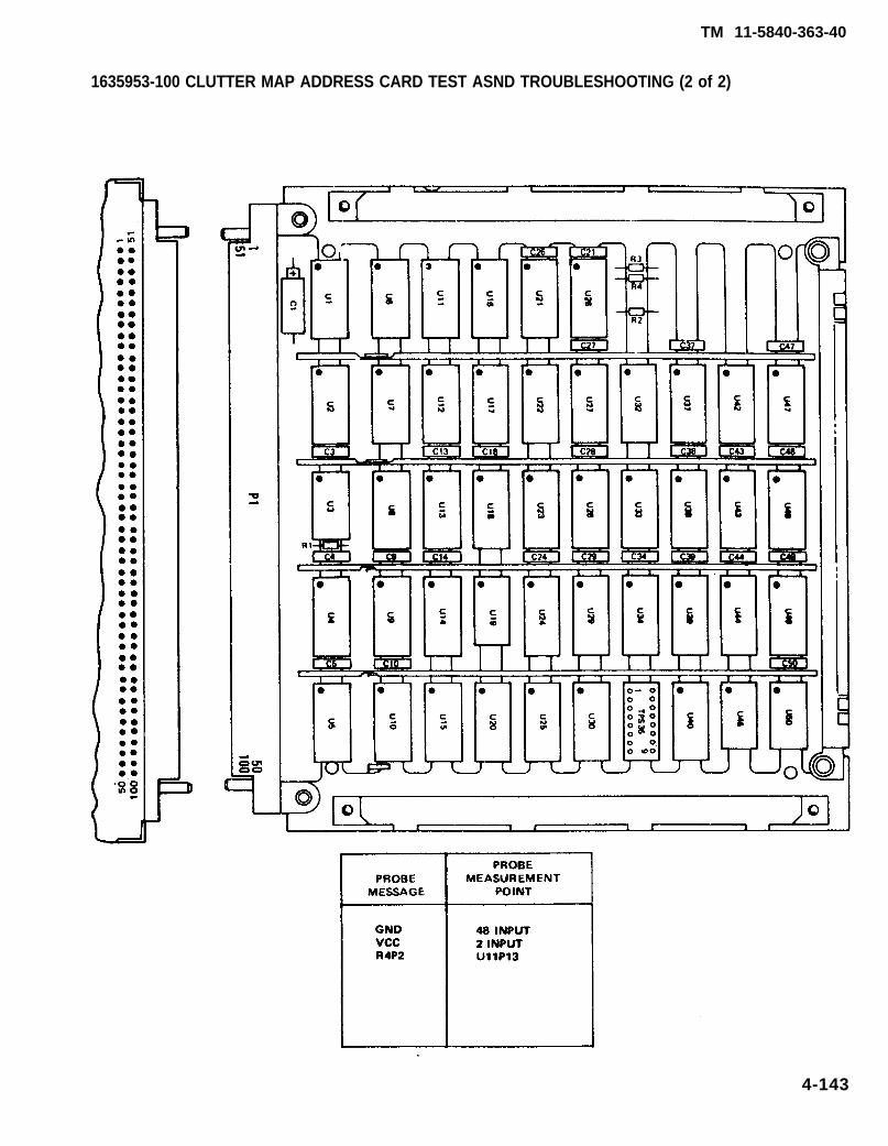
TM 11-5840-363-40
4-143
1635953-100 CLUTTER MAP ADDRESS CARD TEST ASND TROUBLESHOOTING (2 of 2)

TM 11-5840-363-40
1635954-100 CLUTTER MAP INTEGRATOR CARD TEST AND TROUBLESHOOTING (1 of 2)
1. Turn on AN/USM-410(V) tester.a. Perform AN/USM-410(V) tester startup per TM 11-6625-2773-12-1.b. Verify R is displayed on crt. If R is not displayed, turn tester off and restart per TM
11-6625-2773-12-1.c. Type DIR BACKGROUND at terminal and press RETURN key.d. Observe R is displayed on crt.e. At TEST OPERATORS PANEL, select ALL TESTS, VIDEO DISPLAY, and PRINTER.
2. Select test.a. Type TEST 1635954TXX at terminal and press RETURN key. See test program index (page
4-12) for current revision number (the last two digits of the file name).b. Observe the following message on crt. Verify UUT number on top line is correct; disregard
remainder of message. If UUT number is not correct, press and hold COMMAND key andpress HALT key. Release both keys and type in correct test number per step 2a.
TEST-STEP#: LINE#: EQUATE XXUUT: 1635954TXX. IC XX/XX/XX
MEAS VALUE:. . . . . . . . . . . . . . . . . . . . . . . . . . . . . . . . . . . . . . .- RUN TIME SYSTEM REV X.XX -. . . . . . . . . . . . . . . . . . . . . . . . . . . . . . . . . . . . . . .
**PIU CAL APPLIED**BNC CAL APPLIE**LSVSU CAL APPLIED**HSVSU CAL APPLIED
COMPILED USING COMPILER REVISION: X.XXSET SELECTOR SWITCHES. ENTER STARTING TEST STEP:
c. Press PROCEED key to start test.3. Enter part number and manufacturing serial number (MSN).
a. Observe OPERATOR ACTION messages on crt which instruct you to enter the part numberand manufacturing serial number (MSN).
b. Locate these numbers on UUT connector and enter them as directed by crt messages.4. Hook up ID.
a. Observe the following message on crt.OPERATOR ACTIONPERFORM ID HOOKUP AS ILLUSTRATED. SEE TM 11-5840-363-40.
b. Hook up ID per procedure on page 4-18.5. Hook up UUT.
a. Observe the following message on crt.OPERATOR ACTIONPERFORM UUT HOOKUP AS ILLUSTRATED. SEE TM 11-5840-363-40.
Remove ID before performing UUT hookup.
b. Hook up UUT per procedure on page 4-20.6. Test and troubleshoot UUT.
a. Perform any further OPERATOR ACTION messages that appear on crt until test is complete.b. Use diagram on opposite page to locate probe points (nodes) and components.
7. Remove UUT and ID per procedure on page 4-24.8. Turn off AN/USM-410(V) tester per shutdown procedure in TM 11-6625-2773-12-1.
4-144 Change 1

TM 11-5840-364-40
NOTE
THIS CARD REQUIRES AN ADDITIONAL TEST CLIP OR POWER CABLEASSEMBLY DURING TEST. CONSULT TABLE ON PAGE 4-22 TO SELECTAPPROPRIATE EQUIPMENT.
4-145
1635954-100 CLUTTER MAP INTEGRATOR CARD TEST AND TROUBLESHOOTING (1 of 2)

TM 11-5840-363-40
1635955-100 TARGET COUNT CARD TEST AND TROUBLESHOOTING (1 of 2)
1. Turn on AN/USM-410(V) tester.a. Perform AN/USM-410(V) tester startup per TM 11-6625-2773-12-1.b. Verify R is displayed on crt. If R is not displayed, turn tester off and restart per TM
11-6625-2773-12-1.c. Type DIR BACKGROUND at terminal and press RETURN key.d. Observe R is displayed on crt.e. At TEST OPERATORS PANEL, select ALL TESTS, VIDEO DISPLAY, and PRINTER.
2. Select test.a. Type TEST 1635955TXX at terminal and press RETURN key. See test program index (page
4-12) for current revision number (the last two digits of the file name).b. Observe the following message on crt. Verify UUT number on top line is correct; disregard
remainder of message. If UUT number is not correct, press and hold COMMAND key andpress HALT key. Release both keys and type in correct test number per step 2a.
TEST-STEP#: LINE#: EQUATE XXUUT: 1635955TXX. IC XX/XX/XX
MEAS VALUE:---------------------------------------- RUN TIME SYSTEM REV X.XX ----------------------------------------
**PIU CAL APPLIED**BNC CAL APPLIED**LSVSU CAL APPLIED**HSVSU CAL APPLIED
COMPILED USING COMPILER REVISION: X.XXSET SELECTOR SWITCHES. ENTER STARTING TEST STEP:
c. Press PROCEED key to start test.3. Enter part number and manufacturing serial number (MSN)
a. Observe OPERATOR ACTION messages on crt which instruct you to enter the part numberand manufacturing serial number (MSN).
b. Locate these numbers on UUT connector and enter them as directed by crt messages.4. Hook up ID.
a. Observe the following message on crt.OPERATOR ACTIONPERFORM ID HOOKUP AS ILLUSTRATED. SEE TM 11-5840-363-40.
b. Hook up ID per procedure on page 4-18.5. Hook up UUT.
a. Observe the following message on crt.OPERATOR ACTIONPERFORM UUT HOOKUP AS ILLUSTRATED. SEE TM 11-5840-363-40.
Remove ID before performing UUT hookup.
b. Hook up UUT per procedure on page 4-20.6. Test and troubleshoot UUT.
a. Perform any further OPERATOR ACTION messages that appear on crt until test is complete.b. Use diagram on opposite page to locate probe points (nodes) and components.
7. Remove UUT and ID per procedure on page 4-24.8. Turn off AN/USM-410(V) tester per shutdown procedure in TM 11-6625-2773-12-1.
4-146 Change 1

TM 11-5840-363-40
4-147
1635955-100 TARGET COUNT CARD TEST AND TROUBLESHOOTING (2 of 2)

TM 11-5840-363-40
1635956-100 PROCESS CYCLE SIGNAL GENERATOR CARD TEST AND TROUBLESHOOTING (1 of 2)
1. Turn on AN/USM-410(V) tester.a. Perform AN/USM-410(V) tester startup per TM 11-6625-2773-12-1.b. Verify R is displayed on crt. If R is not displayed, turn tester off and restart per TM
11-6625-2773-12-1.c. Type DIR BACKGROUND at terminal and press RETURN key.d. Observe R is displayed on crt.e. At TEST OPERATORS PANEL, select ALL TESTS, VIDEO DISPLAY, and PRINTER.
2. Select test.a. Type TEST 1635956TXX at terminal and press RETURN key. See test program index (page
4-12) for current revision number (the last two digits of the file name).b. Observe the following message on crt. Verify UUT number on top line is correct; disregard
remainder of message. If UUT number is not correct, press and hold COMMAND key andpress HALT key. Release both keys and type in correct test number per step 2a.
TEST-STEP#: LINE#: EQUATE XXUUT: 1635956TXX. IC XX/XX/XX
MEAS VALUE:. . . . .. . . . . . . . . . . . . . . . . . . . . . . . . . . . . . . . . .- RUN TIME SYSTEM REV X.XX -. . . . . . . . . . . . . . . . . . . . . . . . . . . . . . . . . . . . . . .
**PIU CAL APPLIED**BNC CAL APPLIED**LSVSU CAL APPLIED**HSVSU CAL APPLIED
COMPILED USING COMPILER REVISION: X.XXSET SELECTOR SWITCHES. ENTER STARTING TEST STEP:
c. Press PROCEED key to start test.3. Enter part number and manufacturing serial number (MSN).
a. Observe OPERATOR ACTION messages on crt which instruct you to enter the part numberand manufacturing serial number (MSN).
b. Locate these numbers on UUT connector and enter them as directed by crt messages.4. Hook up ID.
a. Observe the following message on crt.OPERATOR ACTIONPERFORM ID HOOKUP AS ILLUSTRATED. SEE TM 11-5840-363-40.
b. Hook up ID per procedure on page 4-18.5. Hook UP UUT.
a. Observe the following message on crt.OPERATOR ACTIONPERFORM UUT HOOKUP AS ILLUSTRATED. SEE TM 11-5840-363-40.
Remove ID before performing UUT hookup.
b. Hook up UUT per procedure on page 4-20.6. Test and troubleshoot UUT.
a. Perform any further OPERATOR ACTION messages that appear on crt until test is complete.b. Use diagram on opposite page to locate probe points (nodes) and components.
7. Remove UUT and ID per procedure on page 4-24.8. Turn off AN/USM-410(V) tester per shutdown procedure in TM 11-6625-2773-12-1.
4-148 Change 1

TM 11-5840-363-40
4-149
1635956-100 PROCESS CYCLE SIGNAL GENERATOR CARD TEST AND TROUBLESHOOTING (2 of 2)

TM 11-5840-363-40
1635957-100 COLLECT CYCLE SIGNAL GENERATOR CARD TEST AND TROUBLESHOOTING (1 of 2)
1. Turn on AN/USM-410(V) tester.a. Perform AN/USM-410(V) tester startup per TM 11-6625-2773-12-1.b. Verify R is displayed on crt. If R is not displayed, turn tester off and restart per TM
11-6625-2773-12-1.c. Type DIR BACKGROUND at terminal and press RETURN key.d. Observe R is displayed on crt.e. At TEST OPERATORS PANEL, select ALL TESTS, VIDEO DISPLAY. and PRINTER.
2. Select test.a. Type TEST 1635957TXX at terminal and press RETURN key. See test program index (page
4-12) for current revision number (the last two digits of the file name).b. Observe the following message on crt. Verify UUT number on top line is correct; disregard
remainder of message. If UUT number is not correct, press and hold COMMAND key andpress HALT key. Release both keys and type in correct test number per step 2a.
TEST-STEP#: LINE#: EQUATE XXUUT: 1635957TXX. IC XX/XX/XX
MEAS VALUE:---------------------------------------– RUN TIME SYSTEM REV X.XX -- ---- - - - - - - - - - - - - - - - - - - - - - - - - - - - - - - - - - -
**PIU CAL APPLIED**BNC CAL APPLIED**LSVSU CAL APPLIED**HSVSU CAL APPLIED
COMPILED USING COMPILER REVISION: X.XXSET SELECTOR SWITCHES. ENTER STARTING TEST STEP:
c. Press PROCEED key to start test.3. Enter part number and manufacturing serial number (MSN).
a. Observe OPERATOR ACTION messages on crt which instruct you to enter the part numberand manufacturing serial number (MSN).
b. Locate these numbers on UUT connector and enter them as directed by crt messages.4. Hook up ID.
a. Observe the following message on crt.OPERATOR ACTIONPERFORM ID HOOKUP AS ILLUSTRATED. SEE TM 11-5840-363-40.
b. Hook up ID per procedure on page 4-18.5. Hook Up UUT.
a. Observe the following message on crt.OPERATOR ACTIONPERFORM UUT HOOKUP AS ILLUSTRATED. SEE TM 11-5840-363-40.
Remove ID before performing UUT hookup.
b. Hook up UUT per procedure on page 4-20.6. Test and troubleshoot UUT.
a. Perform any further OPERATOR ACTION messages that appear on crt until test is complete. b. Use diagram on opposite page to locate probe points (nodes) and components.
7. Remove UUT and ID per procedure on page 4-24.8. Turn off AN/USM-410(V) tester per shutdown procedure in TM 11-6625-2773-12-1.
4-150 Change 1

TM 11-5840-363-40
4-151
1635957-100 COLLECT CYCLE SIGNAL GENERATOR CARD TEST TROUBLESHOOTING (2 of 2)

TM 11-5840-363-40
1635960-100 WRITE CONTROL CARD TEST AND TROUBLESHOOTING (1 of 2)
1. Turn on AN/USM-410(V) tester.a. Perform AN/USM-410(V) tester startup per TM 11-6625-2773-12-1.b. Verify R is displayed on crt. If R is not displayed, turn tester off and restart per TM
11-6625-2773-12-1.c. Type DIR BACKGROUND at terminal and press RETURN key.d. Observe R is displayed on crt.e. At TEST OPERATORS PANEL, select ALL TESTS, VIDEO DISPLAY, and PRINTER.
2. Select test.a. Type TEST 1635960TXX at terminal and press RETURN key. See test program index (page
4-12) for current revision number (the last two digits of the file name).b. Observe the following message on crt. Verify UUT number on top line is correct; disregard
remainder of message. If UUT number is not correct, press and hold COMMAND key andpress HALT key. Release both keys and type in correct test number per step 2a.
TEST-STEP#: LINE#: EQUATE XXUUT: 1635960TXX. IC XX/XX/XX
MEAS VALUE:---------------------------------------– RUN TIME SYSTEM REV X.XX –---------------------------------------
**PIU CAL APPLIED**BNC CAL APPLIED**LSVSU CAL APPLIED**HSVSU CAL APPLIED
COMPILED USING COMPILER REVISION: X.XXSET SELECTOR SWITCHES. ENTER STARTING TEST STEP:
c. Press PROCEED key to start test.3. Enter part number and manufacturing serial number (MSN).
a. Observe OPERATOR ACTION messages on crt which instruct you to enter the part numberand manufacturing serial number (MSN).
b. Locate these numbers on UUT connector and enter them as directed by crt messages.4. Hook up ID.
a. Observe the following message on crt.OPERATOR ACTIONPERFORM ID HOOKUP AS ILLUSTRATED. SEE TM 11-5840-363-40.
b. Hook up ID per procedure on page 4-18.5. Hook up UUT.
a. Observe the following message on crt.OPERATOR ACTIONPERFORM UUT HOOKUP AS ILLUSTRATED. SEE TM 11-5840-363-40.
Remove ID before performing UUT hookup.
b. Hook up UUT per procedure on page 4-20.6. Test and troubleshoot UUT.
a. Perform any further OPERATOR ACTION messages that appear on crt until test is complete.b. Use diagram on opposite page to locate probe points (nodes) and components.
7. Remove UUT and ID per procedure on page 4-24.8. Turn off AN/USM-410(V) tester per shutdown procedure in TM 11-6625-2773-12-1.
4-152 Change 1

TM 11-5840-363-40
4-153
1635960-100 WRITE CONTROL CARD TEST AND TROUBLESHOOTING (2 of 2)

TM 11-5840-363-40
1635961-100 COMMAND DATA CONTROL CARD TEST AND TROUBLESHOOTING (1 of 2)
1. Turn on AN/USM-410(V) tester.a. Perform AN/USM-410(V) tester startup per TM 11-6625-2773-12-1.b. Verify R is displayed on crt. If R is not displayed, turn tester off and restart per TM
11-6625-2773-12-1.c. Type DIR BACKGROUND at terminal and press RETURN key.d. Observe R is displayed on crt.e. At TEST OPERATORS PANEL, select ALL TESTS, VIDEO DISPLAY, and PRINTER.
2. Select test.a. Type TEST 1635961TXX at terminal and press RETURN key. See test program index (page
4-12) for current revision number (the last two digits of the file name).b. Observe the following message on crt. Verify UUT number on top line is correct; disregard
remainder of message. If UUT number is not correct, press and hold COMMAND key andpress HALT key. Release both keys and type in correct test number per step 2a.
TEST-STEP#: LINE#: EQUATE XXUUT: 1635961TXX. IC XX/XX/XX
MEAS VALUE:---------------------------------------- RUN TIME SYSTEM REV X.XX ----------------------------------------
**PIU CAL APPLIED**BNC CAL APPLIED**LSVSU CAL APPLIED**HSVSU CAL APPLIED
COMPILED USING COMPILER REVISION: X.XXSET SELECTOR SWITCHES. ENTER STARTING TEST STEP:
c. Press PROCEED key to start test.3. Enter part number and manufacturing serial number (MSN).
a. Observe OPERATOR ACTION messages on crt which instruct you to enter the part numberand manufacturing serial number (MSN).
b. Locate these numbers on UUT connector and enter them as directed by crt messages.4. Hook up ID.
a. Observe the following message on crt.OPERATOR ACTIONPERFORM ID HOOKUP AS ILLUSTRATED. SEE TM 11-5840-363-40.
b. Hook up ID per procedure on page 4-18.5. Hook up UUT.
a. Observe the following message on crt.OPERATOR ACTIONPERFORM UUT HOOKUP AS ILLUSTRATED. SEE TM 11-5840-363-40.
Remove ID before performing UUT hookup.
b. Hook up UUT per procedure on page 4-20.6. Test and troubleshoot UUT.
a. Perform any further OPERATOR ACTION messages that appear on crt until test is complete.b. Use diagram on opposite page to locate probe points (nodes) and components.
7. Remove UUT and ID per procedure on page 4-24.8. Turn off AN/USM-410(V) tester per shutdown procedure in TM 11-6625-2773-12-1.
4-154 Change 1

TM 11-5840-363-40
4-155
1635961-100 COMMAND DATA CONTROL CARD TEST AND TROUBLESHOOTING (2 of 2)

TM 11-5840-363-40
1635962-100 MEAN LEVEL GENERATOR CARD TEST AND TROUBLESHOOTING (1 of 2)
1. Turn on AN/USM-410(V) tester.a. Perform AN/USM-410(V) tester startup per TM 11-6625-2773-12-1.b. Verify R is displayed on crt. If R is not displayed, turn tester off and restart per TM
11-6625-2773-12-1.c. Type DIR BACKGROUND at terminal and press RETURN key.d. Observe R is displayed on crt.e. At TEST OPERATORS PANEL, select ALL TESTS, VIDEO DISPLAY, and PRINTER.
2. Select test.a. Type TEST 1635962TXX at terminal and press RETURN key. See test program index (page
4-12) for current revision number (the last two digits of the file name).b. Observe the following message on crt. Verify UUT number on top line is correct; disregard
remainder of message. If UUT number is not correct, press and hold COMMAND key andpress HALT key. Release both keys and type in correct test number per step 2a.
TEST-STEP#: LINE#: EQUATE XXUUT: 1635962TXX. IC XX/XX/XX
MEAS VALUE:---------------------------------------- RUN TIME SYSTEM REV X.XX ----------------------------------------
**PIU CAL APPLIED**BNC CAL APPLIED**LSVSU CAL APPLIED**HSVSU CAL APPLIED
COMPILED USING COMPILER REVISION: X.XXSET SELECTOR SWITCHES. ENTER STARTING TEST STEP:
c. Press PROCEED key to start test.3. Enter part number and manufacturing serial number (MSN).
a. Observe OPERATOR ACTION messages on crt which instruct you to enter the part numberand manufacturing serial number (MSN).
b. Locate these numbers on UUT connector and enter them as directed by crt messages.4. Hook up ID.
a. Observe the following message on crt.OPERATOR ACTIONPERFORM ID HOOKUP AS ILLUSTRATED. SEE TM 11-5840-363-40.
b. Hook up lD per procedure on page 4-18.5. Hook up UUT.
a. Observe the following message on crt.OPERATOR ACTIONPERFORM UUT HOOKUP AS ILLUSTRATED. SEE TM 11-5840-363-40.
Remove ID before performing UUT hookup.
b. Hook up UUT per procedure on page 4-20.6. Test and troubleshoot UUT.
a. Perform any further OPERATOR ACTION messages that appear on crt until test is complete.b. Use diagram on opposite page to locate probe points (nodes) and components.
7. Remove UUT and ID per procedure on page 4-24.8. Turn off AN/USM-410(V) tester per shutdown procedure in TM 11-6625-2773-12-1.
4-156 Change 1

TM 11-5840-363-40
4-157
1635962-100 MEAN LEVEL GENERATOR CARD TEST AND TROUBLESHOOTING (2 of 2)

TM 11-5840-363-40
1635963-100 INTEGRATOR AND LOG CONVERTER CARD TEST AND TROUBLESHOOTING (1 of 2)
1. Turn on AN/USM-410(V) tester.a. Perform AN/USM-410(V) tester startup per TM 11-6625-2773-12-1.b. Verify R is displayed on crt. If R is not displayed, turn tester off and restart per TM
11-6625-2773-12-1.c. Type DIR BACKGROUND at terminal and press RETURN key.d. Observe R is displayed on crt.e. At TEST OPERATORS PANEL, select ALL TESTS, VIDEO DISPLAY, and PRINTER.
2. Select test.a. Type TEST 1635963TXX at terminal and press RETURN key. See test program index (page
4-12) for current revision number (the last two digits of the file name).b. Observe the following message on crt. Verify UUT number on top line is correct; disregard
remainder of message. If UUT number is not correct, press and hold COMMAND key andpress HALT key. Release both keys and type in correct test number per step 2a.
TEST-STEP#: LINE#: EQUATE XXUUT: 1635963TXX. IC XX/XX/XX
MEAS VALUE:---------------------------------------– RUN TIME SYSTEM REV X.XX ----------------------------------------
**PIU CAL APPLIED**BNC CAL APPLIED**LSVSU CAL APPLIED**HSVSU CAL APPLIED
COMPILED USING COMPILER REVISION: X.XXSET SELECTOR SWITCHES. ENTER STARTING TEST STEP:
c. Press PROCEED key to start test.3. Enter part number and manufacturing serial number (MSN).
a. Observe OPERATOR ACTION messages on crt which instruct you to enter the part numberand manufacturing serial number (MSN).
b. Locate these numbers on UUT connector and enter them as directed by crt messages.4. Hook up ID.
a. Observe the following message on crt.OPERATOR ACTIONPERFORM ID HOOKUP AS ILLUSTRATED. SEE TM 11-5840-363-40.
b. Hook up ID per procedure on page 4-18.5. Hook up UUT.
a. Observe the following message on crt.OPERATOR ACTIONPERFORM UUT HOOKUP AS ILLUSTRATED. SEE TM 11-5840-363-40.
Remove ID before performing UUT hookup.
b. Hook up UUT per procedure on page 4-20.6. Test and troubleshoot UUT.
a. Perform any further OPERATOR ACTION messages that appear on crt until test is complete.b. Use diagram on opposite page to locate probe points (nodes) and components.
7. Remove UUT and ID per procedure on page 4-24.8. Turn off AN/USM-410(V) tester per shutdown procedure in TM 11-6625-2773-12-1.
4-158 Change 1

TM 11-5840-363-40
4-159
1635963-100 INTEGRATOR AND LOG CONVERTER CARD TEST AND TROUBLESHOOTING (1 of 2)

1635964-100 B-SCOPE INTERFACE CARD TEST AND TROUBLESHOOTlNG (1 of 2)
1. Turn on AN/USM-410(V) tester.a. Perform AN/USM-410(V) tester startup per TM 11-6625-2773-12-1.b. Verify R is displayed on crt. If R is not displayed, turn tester off and restart per TM
11-6625-2773-12-1.c. Type DIR BACKGROUND at terminal and press RETURN key.d. Observe R is displayed on crt.e. At TEST OPERATORS PANEL, select ALL TESTS, VIDEO DISPLAY, and PRINTER.
2. Select test.a
b.
c.
Type TEST 1635964TXX at terminal and press RETURN key. See test program index (page4-12) for current revision number (the last two digits of the file name).Observe the following message on crt. Verify UUT number on top line is correct; disregardremainder of message. If UUT number is not correct, press and hold COMMAND key andpress HALT key. Release both keys and type in correct test number per step 2a.
TEST-STEP#: LINE#: EQUATE XXUUT: 1635964TXX. IC XX/XX/XX
MEAS VALUE:---------------------------------------- RUN TIME SYSTEM REV X.XX ----------------------------------------
**PIU CAL APPLIED**BNC CAL APPLIED**LSVSU CAL APPLIED**HSVSU CAL APPLIED
COMPILED USING COMPILER REVISION: X.XXSET SELECTOR SWITCHES. ENTER STARTING TEST STEP:
Press PROCEED key to start test.3. Enter part number and manufacturing serial number (MSN).
a. Observe OPERATOR ACTION messages on crt which instruct you to enter the part numberand manufacturing serial number (MSN).
b. Locate these numbers on UUT connector and enter them as directed by crt messages.4. Hook up ID.
a. Observe the following message on crt.OPERATOR ACTIONPERFORM ID HOOKUP AS ILLUSTRATED. SEE TM 11-5840-363-40.
b. Hook up lD per procedure on page 4-18.5. Hook up UUT.
a. Observe the following message on crt.OPERATOR ACTIONPERFORM UUT HOOKUP AS ILLUSTRATED. SEE TM 11-5840-363-40.
Remove ID before performing UUT hookup.
b. Hook up UUT per procedure on page 4-20.6. Test and troubleshoot UUT.
a. Perform any further OPERATOR ACTION messages that appear on crt until test is complete. b. Use diagram on opposite page to locate probe points (nodes) and components.
7. Remove UUT and ID per procedure on page 4-24.8. Turn off AN/USM-410(V) tester per shutdown procedure in TM 11-6625-2773-12-1.
4-160 Change 1
TM 11-5840-363-40

TM 11-5840-363-40
4-161
1635964-100 B-SCOPE INTERFACE CARD TEST AND TROUBLESHOOTING (2 of 2)

TM 11-5840-363-40
1635967-100 SWITCH/ALPHA LOGIC LATCH CARD TEST AND TROUBLESHOOTING (1 of 2)L
1. Turn on AN/USM-410(V) tester.a. Perform AN/USM-410(V) tester startup per TM 11-6625-2773-12-1.b. Verify R is displayed on crt. If R is not displayed, turn tester off and restart per TM
11-6625-2773-12-1.c. Type DIR BACKGROUND at terminal and press RETURN key.d. Observe R is displayed on crt.e. At TEST OPERATORS PANEL, select ALL TESTS, VIDEO DISPLAY, and PRINTER.
2. Select test.a. Type TEST 1635967TXX at terminal and press RETURN key. See test program index (page
4-12) for current revision number (the last two digits of the file name).b. Observe the following message on crt. Verify UUT number on top line is correct; disregard
remainder of message. If UUT number is not correct, press and hold COMMAND key andpress HALT key. Release both keys and type in correct test number per step 2a.
TEST-STEP#: LINE#: EQUATE XXUUT: 1635967TXX. IC XX/XX/XX
MEAS VALUE:. . . . . . . . . . . . . . . . . . . . . . . . . . . . . . . . . . . . . . .- RUN TIME SYSTEM REV X.XX -. . . . . . . . . . . . . . . . . . . . . . . . . . . . . . . . . . . . . . .
**PIU CAL APPLIED**BNC CAL APPLIED**LSVSU CAL APPLIED**HSVSU CAL APPLIED
COMPILED USING COMPILER REVISION: X.XXSET SELECTOR SWITCHES. ENTER STARTING TEST STEP:
c. Press PROCEED key to start test.3. Enter part number and manufacturing serial number (MSN).
a. Observe OPERATOR ACTION messages on crt which instruct you to enter the part numberand manufacturing serial number (MSN).
b. Locate these numbers on UUT connector and enter them as directed by crt messages.4. Hook up ID.
a. Observe the following message on crt.OPERATOR ACTIONPERFORM ID HOOKUP AS ILLUSTRATED. SEE TM 11-5840-363-40.
b. Hook up ID per procedure on page 4-18.5. Hook up UUT.
a. Observe the following message on crt.OPERATOR ACTIONPERFORM UUT HOOKUP AS ILLUSTRATED. SEE TM 11-5840-363-40.
Remove ID before performing UUT hookup.
b. Hook up UUT per procedure on page 4-20.6. Test and troubleshoot UUT.
a. Perform any further OPERATOR ACTION messages that appear on crt until test is complete.b. Use diagram on opposite page to locate probe points (nodes) and components.
7. Remove UUT and ID per procedure on page 4-24.8. Turn off AN/USM-410(V) tester per shutdown procedure in TM 11-6625-2773-12-1.
4-162 Change 1
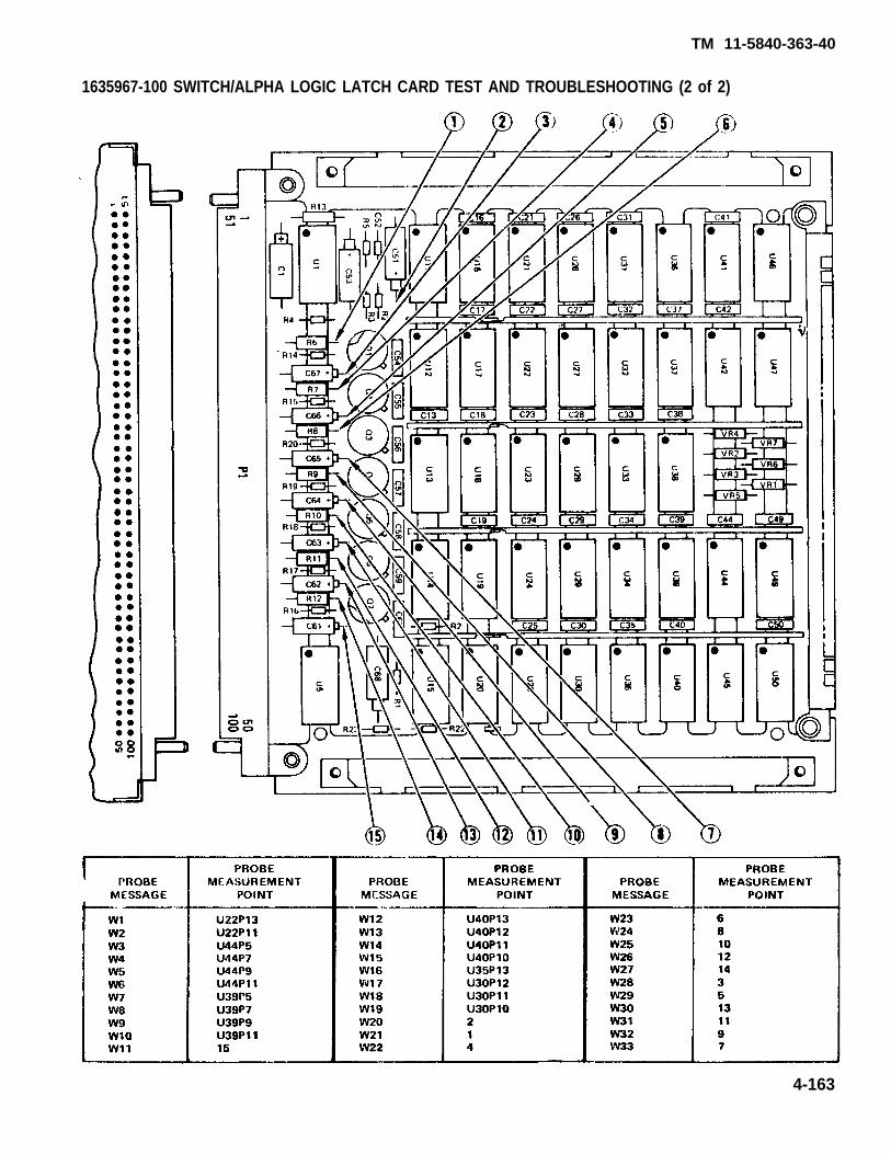
TM 11-5840-363-40
4-163
1635967-100 SWITCH/ALPHA LOGIC LATCH CARD TEST AND TROUBLESHOOTING (2 of 2)

TM 11-5840-363-40
1635968-100 INDICATOR DRIVER CARD TEST AND TROUBLESHOOTING (1 of 2)
1. Turn on AN/USM-410(V) tester.a. Perform AN/USM-410(V) tester startup per TM 11-6625-2773-12-1.b. Verify R is displayed on crt. If R is not displayed, turn tester off and restart per TM
11-6625-2773-12-1.c. Type DIR BACKGROUND at terminal and press RETURN key.d. Observe R is displayed on crt.e. At TEST OPERATORS PANEL, select ALL TESTS, VIDEO DISPLAY, and PRINTER.
2. Select test.a. Type TEST 1635968TXX at terminal and press RETURN key. See test program index (page
4-12) for current revision number (the last two digits of the file name).b. Observe the following message on crt. Verify UUT number on top line is correct; disregard
remainder of message. If UUT number is not correct, press and hold COMMAND key andpress HALT key. Release both keys and type in correct test number per step 2a.
TEST-STEP#: LINE#: EQUATE XXUUT: 1635968TXX. IC XX/XX/XX
MEAS VALUE:---------------------------------------- RUN TIME SYSTEM REV X.XX ----------------------------------------
**PIU CAL APPLIED**BNC CAL APPLIED**LSVSU CAL APPLIED**HSVSU CAL APPLIED
COMPILED USING COMPILER REVISION: X.XXSET SELECTOR SWITCHES. ENTER STARTING TEST STEP:
c. Press PROCEED key to start test.3. Enter part number and manufacturing serial number (MSN).
a. Observe OPERATOR ACTION messages on crt which instruct you to enter the part numberand manufacturing serial number (MSN).
b. Locate these numbers on UUT connector and enter them as directed by crt messages.4. Hook up ID.
a. Observe the following message on crt.OPERATOR ACTIONPERFORM ID HOOKUP AS ILLUSTRATED. SEE TM 11-5840-363-40.
b. Hook up ID per procedure on page 4-18.5. Hook up UUT.
a. Observe the following message on crt.OPERATOR ACTIONPERFORM UUT HOOKUP AS ILLUSTRATED. SEE TM 11-5840-363-40.
Remove ID before performing UUT hookup.
b. Hook up UUT per procedure on page 4-20.6. Test and troubleshoot UUT.
a. Perform any further OPERATOR ACTION messages that appear on crt until test is complete.b. Use diagram on opposite page to locate probe points (nodes) and components.
7. Remove UUT and ID per procedure on page 4-24.8. Turn off AN/USM-410(V) tester per shutdown procedure in TM 11-6625-2773-12-1.
4-164 Change 1

TM 11-5840-363-40
4-165
1635968-100 INDICATOR DRIVER CARD TEST AND TROUBLESHOOTING (1 of 2)

TM 11-5840-363-40
1635969-100 TACFIRE FSK MODULATOR CARD TEST AND TROUBLESHOOTING (1 of 2)
1. Turn on AN/USM-410(V) tester.a. Perform AN/USM-410(V) tester startup per TM 11-6625-2773-12-1.b. Verify R is displayed on crt. If R is not displayed, turn tester off and restart per TM
11-6625-2773-12-1.C. Type DIR BACKGROUND at terminal and press RETURN key.d. Observe R is displayed on crt.e. At TEST OPERATORS PANEL, select ALL TESTS, VIDEO DISPLAY, and PRINTER.
2. Select test.a. Type TEST 1635969TXX at terminal and press RETURN key. See test program index (page
4-12) for current revision number (the last two digits of the file name).b. Observe the following message on crt. Verify UUT number on top line is correct; disregard
remainder of message. If UUT number is not correct, press and hold COMMAND key andpress HALT key. Release both keys and type in correct test number per step 2a.
TEST-STEP#: LINE#: EQUATE XXUUT: 1635969TXX. IC XX/XX/XX
MEAS VALUE:---------------------------------------- RUN TIME SYSTEM REV X.XX ----------------------------------------
**PIU CAL APPLIED**BNC CAL APPLIED**LSVSU CAL APPLIED**HSVSU CAL APPLIED
COMPILED USING COMPILER REVISION: X.XXSET SELECTOR SWITCHES. ENTER STARTING TEST STEP:
c. Press PROCEED key to start test.3. Enter part number and manufacturing serial number (MSN).
a. Observe OPERATOR ACTION messages on crt which instruct you to enter the part numberand manufacturing serial number (MSN).
b. Locate these numbers on UUT connector and enter them as directed by crt messages.4. Hook UP ID.
a. Observe the following message on crt.OPERATOR ACTIONPERFORM ID HOOKUP AS ILLUSTRATED. SEE TM 11-5840-363-40.
b. Hook up ID per procedure on page 4-18.5. Hook up UUT.
a. Observe the following message on crt.OPERATOR ACTIONPERFORM UUT HOOKUP AS ILLUSTRATED. SEE TM 11-5840-363-40.
Remove ID before performing UUT hookup.
b. Hook up UUT per procedure on page 4-20.6. Test and troubleshoot UUT.
a. Perform any further OPERATOR ACTION messages that appear on crt until test is complete.b. Use diagram on opposite page to locate probe points (nodes) and components.
7. Remove UUT and ID per procedure on page 4-24.8. Turn off AN/USM-410(V) tester per shutdown procedure in TM 11-6625-2773-12-1.
4-166 Change 1

TM 11-5840-363-40
4-167
1635969-100 TACFIRE FSK MODULATOR CARD TEST AND TROUBLESHOOTING (2 of 2)
1635970-100 EASTING ROW/COLUMN DRIVER CARD TEST AND TROUBLESHOOTING (1 of 2)
1. Turn on AN/USM-410(V) tester.a. Perform AN/USM-410(V) tester startup per TM 11-6625-2773-12-1.b. Verify R is displayed on crt. If R is not displayed, turn tester off and restart per TM
11-6625-2773-12-1 .c. Type DIR BACKGROUND at terminal and press RETURN key.d. Observe R is displayed on crt.a. At TEST OPERATORS PANEL, select ALL TESTS, VIDEO DISPLAY, and PRINTER.
2. Select test.a. Type TEST 1635970TXX at terminal and press RETURN key. See test program index (page
4-12) for current revision number (the last two digits of the file name).b. Observe the following message on crt. Verify UUT number on top line is correct; disregard
remainder of message. If UUT number is not correct press and hold COMMAND key andpress HALT key. Release both keys and type in correct test number per step 2a.
TEST-STEP#: LINE#: EQUATE XXUUT: 1635970TXX. IC XX/XX/XX
MEAS VALUE:---------------------------------------- RUN TIME SYSTEM REV X.XX ----------------------------------------
**PIU CAL APPLIED**BNC CAL APPLIED**LSVSU CAL APPLIED**HSVSU CAL APPLIED
COMPILED USING COMPILER REVISION: X.XXSET SELECTOR SWITCHES. ENTER STARTING TEST STEP:
c. Press PROCEED key to start test.3. Enter part number and manufacturing serial number (MSN).
a. Observe OPERATOR ACTION messages on crt which instruct you to enter the part numberand manufacturing serial number (MSN).
b. Locate these numbers on UUT connector and enter them as directed by crt messages.4. Hook up ID.
a. Observe the following message on crt.OPERATOR ACTIONPERFORM ID HOOKUP AS ILLUSTRATED. SEE TM 11-5840-363-40.
b. Hook up ID per procedure on page 4-18.5. Hook up UUT.
a. Observe the following message on crt.OPERATOR ACTIONPERFORM UUT HOOKUP AS ILLUSTRATED. SEE TM 11-5840-363-40.
Remove ID before performing UUT hookup.
b. Hook up UUT per procedure on page 4-20.6. Test and troubleshoot UUT.
a. Perform any further OPERATOR ACTION messages that appear on crt until test is complete.b. Use diagram on opposite page to locate probe points (nodes) and components.
7. Remove UUT and ID per procedure on page 4-24.8. Turn off AN/USM-410(V) tester per shutdown procedure in TM 11-6625-2773-12-1.
4-168 Change 1
TM 11-5840-363-40

TM 11-5840-363-40
4-169
1635970-100 EASTING ROW/COLUMN DRIVER CARD TEST AND TROUBLESHOOTING (2 OF 2)

TM 11-5840-363-40
1635971-100 MAP CONTROL CARD TEST AND TROUBLESHOOTING (1 of 2)
1. Turn on AN/USM-410(V) tester.a. Perform AN/USM-410(V) tester startup per TM 11-6625-2773-12-1.b. Verify R is displayed on crt. If R is not displayed, turn tester off and restart per TM
11-6625-2773-12-1.c. Type DIR BACKGROUND at terminal and press RETURN key.d. Observe R is displayed on crt.e. At TEST OPERATORS PANEL, select ALL TESTS, VIDEO DISPLAY, and PRINTER.
2. Select test.a. Type TEST 1635971TXX at terminal and press RETURN key. See test program index (page
4-12) for current revision number (the last two digits of the file name).b. Observe the following message on crt. Verify UUT number on top line is correct; disregard
remainder of message. If UUT number is not correct, press and hold COMMAND key andpress HALT key. Release both keys and type in correct test number per step 2a.
TEST-STEP#: LINE#: EQUATE XXUUT: 1635971TXX. IC XX/XX/XX
MEAS VALUE:---------------------------------------- RUN TIME SYSTEM REV X.XX -- - - - - - - - - - - - - - - - - - - - - - - - - - - - - - - - - - - - - - -
**PIU CAL APPLIED**BNC CAL APPLIED**LSVSU CAL APPLIED**HSVSU CAL APPLIED
COMPILED USING COMPILER REVISION: X.XXSET SELECTOR SWITCHES. ENTER STARTING TEST STEP:
c. Press PROCEED key to start test.3. Enter part number and manufacturing serial number (MSN).
a. Observe OPERATOR ACTION messages on crt which instruct you to enter the part numberand manufacturing serial number (MSN).
b. Locate these numbers on UUT connector and enter them as directed by crt messages.4. Hook up ID.
a. Observe the following message on crt.OPERATOR ACTIONPERFORM ID HOOKUP AS ILLUSTRATED. SEE TM 11-5840-363-40.
b. Hook up ID per procedure on page 4-18.5. Hook up UUT.
a. Observe the following message on crt.OPERATOR ACTIONPERFORM UUT HOOKUP AS ILLUSTRATED. SEE TM 11-5840-363-40.
Remove ID before performing UUT hookup.
b. Hook up UUT per procedure on page 4-20.6. Test and troubleshoot UUT.
a. Perform any further OPERATOR ACTION messages that appear on crt until test is complete.b. Use diagram on opposite page to locate probe points (nodes) and components.
7. Remove UUT and ID per procedure on page 4-24.8. Turn off AN/USM-410(V) tester per shutdown procedure in TM 11-6625-2773-12-1.
4-170 Change 1

TM 11-5840-363-40
4-171
1635971-100 MAP CONTROL CARD TEST AND TROUBLESHOOTING (2 OF 2)

TM 11-5840-363-40
1635973-100 PERIPHERAL INPUT/OUTPUT CONTROL CARD TEST AND TROUBLESHOOTING (1 of 2)
1. Turn on AN/USM-410(V) tester.a. Perform AN/USM-410(V) tester startup per TM 11-6625-2773-12-1.b. Verify R is displayed on crt. If R is not displayed, turn tester off and restart per TM
11-6625-2773-12-1.c. Type DIR BACKGROUND at terminal and press RETURN key.d. Observe R is displayed on crt.e. At TEST OPERATORS PANEL, select ALL TESTS, VIDEO DISPLAY, and PRINTER.
2. Select test.a. Type TEST 1635973TXX at terminal and press RETURN key. See test program index (page
4-12) for current revision number (the last two digits of the file name).b. Observe the following message on crt. Verify UUT number on top line is correct; disregard
remainder of message. If UUT number is not correct, press and hold COMMAND key andpress HALT key. Release both keys and type in correct test number per step 2a.
TEST-STEP#: LINE#: EQUATE XXUUT: 1635973TXX. IC XX/XX/XX
MEAS VALUE:---------------------------------------– RUN TIME SYSTEM REV X.XX –---------------------------------------
**PIU CAL APPLIED**BNC CAL APPLIED**LSVSU CAL APPLIED**HSVSU CAL APPLIED
COMPILED USING COMPILER REVISION: X.XXSET SELECTOR SWITCHES, ENTER STARTING TEST STEP:
c. Press PROCEED key to start test.3. Enter part number and manufacturing serial number (MSN).
a. Observe OPERATOR ACTION messages on crt which instruct you to enter the part numberand manufacturing serial number (MSN).
b. Locate these numbers on UUT connector and enter them as directed by crt messages.4. Hook up ID.
a. Observe the following message on crt.OPERATOR ACTIONPERFORM ID HOOKUP AS ILLUSTRATED. SEE TM 11-5840-363-40.
h. Hook up ID per procedure on page 4-18.5. Hook up UUT.
a. Observe the following message on crt.OPERATOR ACTIONPERFORM UUT HOOKUP AS ILLUSTRATED. SEE TM 11-5840-363-40.
Remove ID before performing UUT hookup.
b. Hook up UUT per procedure on page 4-20.6. Test and troubleshoot UUT.
a. Perform any further OPERATOR ACTION messages that appear on crt until test is complete.b. Use diagram on opposite page to locate probe points (nodes) and components.
7. Remove UUT and ID per procedure on page 4-24.8. Turn off AN/USM-410(V) tester per shutdown procedure in TM 11-6625-2773-12-1.
4-172 Change 1
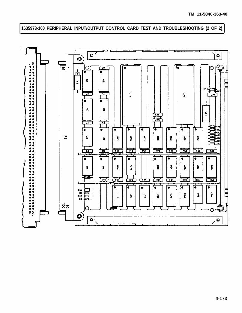
TM 11-5840-363-40
4-173
1635973-100 PERIPHERAL INPUT/OUTPUT CONTROL CARD TEST AND TROUBLESHOOTING (2 OF 2)

TM 11-5840-363-40
1635975-100 CLUTTER MAP TRACK UPDATE CARD TEST AND TROUBLESHOOTING (1 of 2)
1. Turn on AN/USM-410(V) tester.a. Perform AN/USM-410(V) tester startup per TM 11-6625-2773-12-1.b. Verify R is displayed on crt. If R is not displayed, turn tester off and restart per TM
11-6625-2773-12-1.c. Type DIR BACKGROUND at terminal and press RETURN key.d. Observe R is displayed on crt.e. At TEST OPERATORS PANEL, select ALL TESTS, VIDEO DISPLAY, and PRINTER.
2. Setect test.a. Type TEST 1635975TXX at terminal and press RETURN key. See test program index (page
4-12) for current revision number (the last two digits of the file name).b. Observe the following message on crt. Verify UUT number on top line is correct; disregard
remainder of message. If UUT number is not correct, press and hold COMMAND key andpress HALT key. Release both keys and type in correct test number per step 2a.
TEST-STEP#: LINE#: EQUATE XXUUT: 1635975TXX. IC XX/XX/XX
MEAS VALUE:---------------------------------------- RUN TIME SYSTEM REV X.XX ----------------------------------------
**PIU CAL APPLIED**BNC CAL APPLIED**LSVSU CAL APPLIED**HSVSU CAL APPLIED
COMPILED USING COMPILER REVISION: X.XXSET SELECTOR SWITCHES. ENTER STARTING TEST STEP:
c. Press PROCEED key to start test.3. Enter part number and manufacturing serial number (MSN).
a. Observe OPERATOR ACTION messages on crt which instruct you to enter the part numberand manufacturing serial number (MSN).
b. Locate these numbers on UUT connector and enter them as directed by crt messages.4. Hook up ID.
a. Observe the following message on crt.OPERATOR ACTIONPERFORM ID HOOKUP AS ILLUSTRATED. SEE TM 11-5840-363-40.
b. Hook up ID per procedure on page 4-18.5. Hook up UUT.
a. Observe the following message on crt.OPERATOR ACTIONPERFORM UUT HOOKUP AS ILLUSTRATED. SEE TM 11-5840-363-40.
Remove ID before performing UUT hookup.
b. Hook up UUT per procedure on page 4-20.6. Test and troubleshoot UUT.
a. Perform any further OPERATOR ACTION messages that appear on crt until test is complete.b. Use diagram on opposite page to locate probe points (nodes) and components.
7. Remove UUT and ID per procedure on page 4-24.8. Turn off AN/USM-410(V) tester per shutdown procedure in TM 11-6625-2773-12-1.
4-174 Change 1

TM 11-5840-363-40
4-175
1635975-100 CLUTTER MAP TRACK UPDATE CARD TEST AND TROUBLESHOOTING (2 of 2)

TM 11-5840-363-40
1635976-100 POWER SUPPLY BITE CARD TEST AND TROUBLESHOOTING (1 of 2)
1. Turn on AN/USM-410(V) tester.a. Perform AN/USM-410(V) tester startup per TM 11-6625-2773-12-1.b. Verify R is displayed on crt. If R is not displayed, turn tester off and restart per TM
11-6625-2773-12-1.c. Type DIR BACKGROUND at terminal and press RETURN key.d. Observe R is displayed on crt.e. At TEST OPERATORS PANEL, select ALL TESTS, VIDEO DISPLAY, and PRINTER.
2. Select test.a. Type TEST 1635976TXX at terminal and press RETURN key. See test program index (page
4-12) for current revision number (the last two digits of the file name).b. Observe the following message on crt. Verify UUT number on top line is correct; disregard
remainder of message. If UUT number is not correct, press and hold COMMAND key andpress HALT key. Release both keys and type in correct test number per step 2a.
TEST-STEP#: LINE#: EQUATE XXUUT: 1635976TXX. IC XX/XX/XX
MEAS VALUE:. . . . . . . . . . . . . . . . . . . . . . . . . . . . . . . . . . . . . . .- RUN TIME SYSTEM REV X.XX -. . . . . . . . . . . . . . . . . . . . . . . . . . . . . . . . . . . . . . .
**PIU CAL APPLIED**BNC CAL APPLIED**LSVSU CAL APPLIED**HSVSU CAL APPLIED
COMPILED USING COMPILER REVISION: X.XXSET SELECTOR SWITCHES. ENTER STARTING TEST STEP:
c. Press PROCEED key to start test.3. Enter part number and manufacturing serial number (MSN).
a. Observe OPERATOR ACTION messages on crt which instruct you to enter the part numberand manufacturing serial number (MSN).
b. Locate these numbers on UUT connector and enter them as directed by crt messages.4. Hook up ID.
a. Observe the following message on crt.OPERATOR ACTIONPERFORM ID HOOKUP AS ILLUSTRATED. SEE TM 11-5840-363-40.
b. Hook up ID per procedure on page 4-18.5. Hook up UUT.
a. Observe the following message on crt.OPERATOR ACTIONPERFORM UUT HOOKUP AS ILLUSTRATED. SEE TM 11-5840-363-40.
Remove ID before performing UUT hookup.
b. Hook up UUT per procedure on page 4-20.6. Test and troubleshoot UUT.
a. Perform any further OPERATOR ACTION messages that appear on crt until test is complete.b. Use diagram on opposite page to locate probe points (nodes) and components.
7. Remove UUT and ID per procedure on page 4-24.8. Turn off AN/USM-410(V) tester per shutdown procedure in TM 11-6625-2773-12-1.
4-176 Change 1

TM 11-5840-363-40
4-177
1635976-100 POWER SUPPLY BITE CARD TEST AND TROUBLESHOOTING (2 of 2)

TM 11-5840-363-40
1635977-100 TACFIRE DATA STORAGE CARD TEST AND TROUBLESHOOTING (1 of 2)
1. Turn on AN/USM-410(V) tester.a. Perform AN/USM-410(V) tester startup per TM 11-6625-2773-12-1.b. Verify R is displayed on crt. If R is not displayed, turn tester off and restart per TM
11-6625-2773-12-1.c. Type DIR BACKGROUND at terminal and press RETURN key.d. Observe R is displayed on crt.e. At TEST OPERATORS PANEL, select ALL TESTS, VIDEO DISPLAY, and PRINTER.
2. Select test.a.
b.
c.
Type TEST 1635977TXX at terminal and press RETURN key. See test program index (page4-12) for current revision number (the last two digits of the file name).Observe the following message on crt. Verify UUT number on top line is correct; disregardremainder of message. If UUT number is not correct, press and hold COMMAND key andpress HALT key. Release both keys and type in correct test number per step 2a.
TEST-STEP#: LINE#: EQUATE XXUUT: 1635977TXX. IC XX/XX/XX
MEAS VALUE:- - - - - - - - - - - - - - - - - - - - - - - - - - - - - - - - - - - - - - -- RUN TIME SYSTEM REV X.XX ----------------------------------------
**PIU CAL APPLIED**BNC CAL APPLIED**LSVSU CAL APPLIED**HSVSU CAL APPLIED
COMPILED USING COMPILER REVISION: X.XXSET SELECTOR SWITCHES. ENTER STARTING TEST STEP:
Press PROCEED key to start test.3. Enter part number and manufacturing serial number (MSN).
a. Observe OPERATOR ACTION messages on crt which instruct you to enter the part numberand manufacturing serial number (MSN).
b. Locate these numbers on UUT connector and enter them as directed by crt messages.4. Hook up ID.
a. Observe the following message on crt.OPERATOR ACTIONPERFORM ID HOOKUP AS ILLUSTRATED. SEE TM 11-5840-363-40.
b. Hook up ID per procedure on page 4-18.5. Hook up UUT.
a. Observe the following message on crt.OPERATOR ACTIONPERFORM UUT HOOKUP AS ILLUSTRATED. SEE TM 11-5840-363-40.
Remove ID before performing UUT hookup.
b. Hook up UUT per procedure on page 4-20.6. Test and troubleshoot UUT.
a. Perform any further OPERATOR ACTION messages that appear on crt until test is complete.b. Use diagram on opposite page to locate probe points (nodes) and components.
7. Remove UUT and ID per procedure on page 4-24.8. Turn Off AN/USM-410(V) tester per shutdown procedure in TM 11-6625-2773-12-1.
4-178 Change 1

TM 11-5840-363-40
4-179
1635977-100 TACFIRE DATA STORAGE CARD TEST AND TROUBLESHOOTING (2 of 2)

1635978-100 TACFIRE FSK DEMODULATOR CARD TEST AND TROUBLESHOOTING (1 of 2)
1. Turn on AN/USM-410(V) tester.a. Perform AN/USM-410(V) tester startup per TM 11-6625-2773-12-1.b. Verify R is displayed on crt. If R is not displayed, turn tester off and restart per TM
11-6625-2773-12-1.c. Type DlR BACKGROUND at terminal and press RETURN key.d. Observe R is displayed on crt.e. At TEST OPERATORS PANEL, select ALL TESTS, VIDEO DISPLAY, and PRINTER.
2. Select test.a. Type TEST 1635976TXX at terminal and press RETURN key. See test program index (page
4-12) for current revision number (the last two digits of the file name).b. Observe the following message on crt. Verify UUT number on top line is correct; disregard
remainder of message. If UUT number is not correct, press and hold COMMAND key andpress HALT key. Release both keys and type in correct test number per step 2a.
TEST-STEP#: LINE#: EQUATE XXUUT: 1635978TXX. IC XX/XX/XX
MEAS VALUE:. . . . . . . . . . . . . . . . . . . . . . . . . . . . . . . . . . . . . . .- RUN TIME SYSTEM REV X.XX -. . . . . . . . . . . . . . . . . . . . . . . . . . . . . . . . . . . . . . .
**PIU CAL APPLIED**BNC CAL APPLIED**LSVSU CAL APPLIED**HSVSU CAL APPLIED
COMPILED USING COMPILER REVISION: X.XXSET SELECTOR SWITCHES. ENTER STARTING TEST STEP:
c. Press PROCEED key to start test.3. Enter part number and manufacturing serial number (MSN).
a. Observe OPERATOR ACTION messages on crt which instruct you to enter the part numberand manufacturing serial number (MSN).
b. Locate these numbers on UUT connector and enter them as directed by crt messages.4. Hook up ID.
a. Observe the following message on crt.OPERATOR ACTIONPERFORM ID HOOKUP AS ILLUSTRATED. SEE TM 11-5840-363-40.
b. Hook up ID per procedure on page 4-18.5. Hook up UUT.
a. Observe the following message on crt.OPERATOR ACTIONPERFORM UUT HOOKUP AS ILLUSTRATED. SEE TM 11-5840-363-40.
Remove ID before performing
b. Hook up UUT per procedure on page 4-20.6. Test and troubleshoot UUT.
a. Perform any further OPERATOR ACTION messages
UUT hookup.. .
that appear on crt until test is complete. b. Use diagram on opposite page to locate probe points (nodes) and components.
7. Remove UUT and ID per procedure on page 4-24.8. Turn off AN/USM-410(V) tester per shutdown procedure in TM 11-6625-2773-12-1.
4-180 Change 1
TM 11-5840-363-40

TM 11-5840-363-40
4-181
1635978-100 TACFIRE FSK DEMODULATOR CARD TEST AND TROUBLESHOOTING (2 of 2)

TM 11-5840-363-40
1635979-100 TACFIRE TIMING CARD TEST AND TROUBLESHOOTING (1 of 2)
1. Turn on AN/USM-410(V) tester.a. Perform AN/USM-410(V) tester startup per TM 11-6625-2773-12-1.b. Verify R is displayed on crt. If R is not displayed, turn tester off and restart per TM
11-6625-2773-12-1.c. Type DIR BACKGROUND at terminal and press RETURN key.d. Observe R is displayed on crt.e. At TEST OPERATORS PANEL, select ALL TESTS, VIDEO DISPLAY, and PRINTER.
2. Select test.a. Type TEST 1635979TXX at terminal and press RETURN key. See test program index (page
4-12) for current revision number (the last two digits of the file name).b. Observe the foIlowing message on crt. Verify UUT number on top line is correct; disregard
remainder of message. If UUT number is not correct, press and hold COMMAND key andpress HALT key. Release both keys and type in correct test number per step 2a.
TEST-STEP#: LINE#: EQUATE XXUUT: 1635979TXX. IC XX/XX/XX
MEAS VALUE:. . . . . . . . . . . . . . . . . . . . . . . . . . . . . . . . . . . . . . .- RUN TIME SYSTEM REV X.XX -. . . . . . . . . . . . . . . . . . . . . . . . . . . . . . . . . . . . . . .
**PIU CAL APPLIED**BNC CAL APPLIED**LSVSU CAL APPLIED**HSVSU CAL APPLIED
COMPILED USING COMPILER REVISION: X.XXSET SELECTOR SWITCHES. ENTER STARTING TEST STEP:
c. Press PROCEED key to start test.3. Enter part number and manufacturing serial number (MSN).
a. Observe OPERATOR ACTION messages on crt which instruct you to enter the part numberand manufacturing serial number (MSN).
b. Locate these numbers on UUT connector and enter them as directed by crt messages.4. Hook up ID.
a. Observe the following message on crt.OPERATOR ACTIONPERFORM ID HOOKUP AS ILLUSTRATED. SEE TM 11-5840-363-40.
b. Hook up ID per procedure on page 4-18.5. Hook up UUT.
a. Observe the following message on crt.OPERATOR ACTIONPERFORM UUT HOOKUP AS ILLUSTRATED. SEE TM 11-5840-363-40.
Remove ID before performing UUT hookup.
b. Hook up UUT per procedure on page 4-20.6. Test and troubleshoot UUT.
a. Perform any further OPERATOR ACTION messages that appear on crt until test is complete.b. Use diagram on opposite page to locate probe points (nodes) and components.
7. Remove UUT and ID per procedure on page 4-24.8. Turn off AN/USM-410(V) tester per shutdown procedure in TM 11-6625-2773-12-1.
4-182 Change 1

TM 11-5840-363-40
1635979-100 TACFIRE TIMING CARD TEST AND TROUBLESHOOTING (2 of 2)
4-183
TM 11-5840-363-40
1635985-100 TRAILER SYNC CARD TEST AND TROUBLESHOOTING (1 of 2)
1. Turn on AN/USM-410(V) tester.a. Perform AN/USM-410(V) tester startup per TM 11-6625-2773-12-1.b. Verify R is displayed on crt. If R is not displayed, turn tester off and restart per TM
11-6625-2773-12-1.c. Type DIR BACKGROUND at terminal and press RETURN key.d. Observe R is displayed on crt.e. At TEST OPERATORS PANEL, select ALL TESTS, VIDEO DISPLAY, and PRINTER.
2, Select test.a. Type TEST 1635985TXX at terminal and press RETURN key. See test program index (page
4-12) for current revision number (the last two digits of the file name).b. Observe the following message on crt. Verify UUT number on top line is correct; disregard
remainder of message. If UUT number is not correct, press and hold COMMAND key andpress HALT key. Release both keys and type in correct test number per step 2a.
TEST-STEP#: LINE#: EQUATE XXUUT: 1635985TXX. IC XX/XX/XX
MEAS VALUE:---------------------------------------– RUN TIME SYSTEM REV X.XX –---------------------------------------
** PIU CAL APPLIED** BNC CAL APPLIED** LSVSU CAL APPLIED** HSVSU CAL APPLIED
COMPILED USING COMPILER REVISION: X,XXSET SELECTOR SWITCHES. ENTER STARTING TEST STEP:
c. Press PROCEED key to start test.3. Enter part number and manufacturing serial number (MSN).
a. Observe OPERATOR ACTION messages on crt which instruct you to enter the part numberand manufacturing serial number (MSN).
b. Locate these numbers on UUT connector and enter them as directed by crt messages.4. Hook Up ID.
a. Observe the following message on crt.OPERATOR ACTIONPERFORM ID HOOKUP AS ILLUSTRATED. SEE TM 11-5840-363-40.
b. Hook up ID per procedure on page 4-18.5. Hook Up UUT.
a. Observe the following message on crt.OPERATOR ACTIONPERFORM UUT HOOKUP AS ILLUSTRATED. SEE TM 11-5840-363-40.
Remove ID before performing UUT hookup.
b. Hook up UUT per procedure on page 4-20.6. Test and troubleshoot UUT.
a. Perform any further OPERATOR ACTION messages that appear on crt until test is complete.b. Use diagram on opposite page to locate probe points (nodes) and components.
7. Remove UUT and ID per procedure on page 4-24.8. Turn off AN/USM-410(V) tester per shutdown procedure in TM 11-6625-2773-12-1.
4-184 Change 1

TM 11-5840-363-40
1635985-100 TRAILER SYNC CARD TEST AND TROUBLESHOOTING (2 of 2)
4-185

TM 11-5840-363-40
1635986-100 DATA BUS ENCODER CARD TEST AND TROUBLESHOOTING (1 of 2)
1. Turn on AN/USM-410(V) tester.a. Perform AN/USM-410(V) tester startup per TM 11-6625-2773-12-1.b. Verify R is displayed on crt. If R is not displayed, turn tester off and restart per TM
11-6625-2773-12-1.c. Type DIR BACKGROUND at terminal and press RETURN key.d. Observe R is displayed on crt.e. At TEST OPERATORS PANEL, select ALL TESTS, VIDEO DISPLAY, and PRINTER.
2. Select test.a. Type TEST 1635986TXX at terminal and press RETURN key. See test program index (page
4-12) for current revision number (the last two digits of the file name).b. Observe the following message on crt. Verify UUT number on top line is correct; disregard
remainder of message. If UUT number is not correct, press and hold COMMAND key andpress HALT key. Release both keys and type in correct test number per step 2a.
TEST-STEP#: LiNE#: EQUATE XXUUT: 1635986TXX. IC XX/XX/XX
MEAS VALUE:. . . . . . . . . . . . . . . . . . . . . . . . . . . . . . . . . . . . . . .- RUN TIME SYSTEM REV X.XX -. . . . . . . . . . . . . . . . . . . . . . . . . . . . . . . . . . . . . . .
**PIU CAL APPLIED**BNC CAL APPLIED**LSVSU CAL APPLIED**HSVSU CAL APPLIED
COMPILED USING COMPILER REVISION: X.XXSET SELECTOR SWITCHES. ENTER STARTING TEST STEP:
c. Press PROCEED key to start test.3. Enter part number and manufacturing serial number (MSN).
a. Observe OPERATOR ACTION messages on crt which instruct you to enter the part numberand manufacturing serial number (MSN).
b. Locate these numbers on UUT connector and enter them as directed by crt messages.4. Hook up ID.
a. Observe the following message on crt.OPERATOR ACTIONPERFORM ID HOOKUP AS ILLUSTRATED. SEE TM 11-5840-363-40.
b. Hook up ID per procedure on page 4-18.5. Hook up UUT.
a. Observe the following message on crt.OPERATOR ACTIONPERFORM UUT HOOKUP AS ILLUSTRATED. SEE TM 11-5840-363-40.
Remove ID before performing UUT hookup.
b. Hook up UUT per procedure on page 4-20.6. Test and troubleshoot UUT.
a. Perform any further OPERATOR ACTION messages that appear on crt until test is complete. b. Use diagram on opposite page to locate probe points (nodes) and components.
7. Remove UUT and ID per procedure on page 4-24.8. Turn off AN/USM-410(V) tester per shutdown procedure in TM 11-6625-2773-12-1.
4-186 Change 1

TM 11-5840-363-40
1635986-100 DATA BUS ENCODER CARD TEST AND TROUBLESHOOTING (2 of 2)
PROBEMEASUREMENT
POINTPROBE
MESSAGE
48 INPUT2 INPUT
GNDVCC
4-187

TM 11-5840-363-40
1635987-100 TEMPERATURE CONVERTER CARD TEST AND TROUBLESHOOTING (1 of 2)
1. Turn on AN/USM-410(V) tester.a. Perform AN/USM-410(V) tester startup per TM 11-6625-2773-12-1.b. Verify R is displayed on crt. If R is not displayed, turn tester off and restart per TM
11-6625-2773-12-1.c. Type DIR BACKGROUND at terminal and press RETURN key.d. Observe R is displayed on crt.e. At TEST OPERATORS PANEL, select ALL TESTS, VIDEO DISPLAY, and PRlNTER.
2. Select test.a. Type TEST 1635987TXX at terminal and press RETURN key. See test program index (page
4-12) for current revision number (the last two digits of the file name).b. Observe the following message on crt. Verify UUT number on top line is correct; disregard
remainder of message. If UUT number is not correct, press and hold COMMAND key andpress HALT key. Release both keys and type in correct test number per step 2a.
TEST-STEP#: LINE#: EOUATE XXUUT: 1635987TXX. IC XX/XX/XX
MEAS VALUE:- - - - - - - - - - - - - - - - - - - - - - - - - -- RUN TIME SYSTEM REV X.XX -. . . . . . . . . . . . . . . . . . . . . . . . . . . . . . . . . . . . . . .
**PIU CAL APPLIED**BNC CAL APPLIED**LSVSU CAL APPLIED**HSVSU CAL APPLIED
COMPILED USING COMPILER REVlSlON: X.XXSET SELECTOR SWITCHES, ENTER STARTING TEST STEP:
c. Press PROCEED key to start test.3. Enter part number and manufacturing serial number (MSN).
a. Observe OPERATOR ACTION messages on crt which instruct you to enter the part numberand manufacturing serial number (MSN).
b. Locate these numbers on UUT connector and enter them as directed by crt messages.4. Hook up ID.
a. Observe the following message on crt.OPERATOR ACTIONPERFORM ID HOOKUP AS ILLUSTRATED. SEE TM 11-5840-363-40.
b. Hook up ID per procedure on page 4-18.5. Hook up UUT.
a. Observe the following message on crt.OPERATOR ACTIONPERFORM UUT HOOKUP AS ILLUSTRATED. SEE TM 11-5840-363-40.
Remove ID before performing UUT hookup.
b. Hook up UUT per procedure on page 4-20.6. Test and troubleshoot UUT.
a. Perform any further OPERATOR ACTION messages that appear on crt until test is complete. b. Use diagram on opposite page to locate probe points (nodes) and components.
7. Remove UUT and ID per procedure on page 4-24.8. Turn off AN/USM-410(V) tester per shutdown procedure in TM 11-6625-2773-12-1.
4-188 Change 1
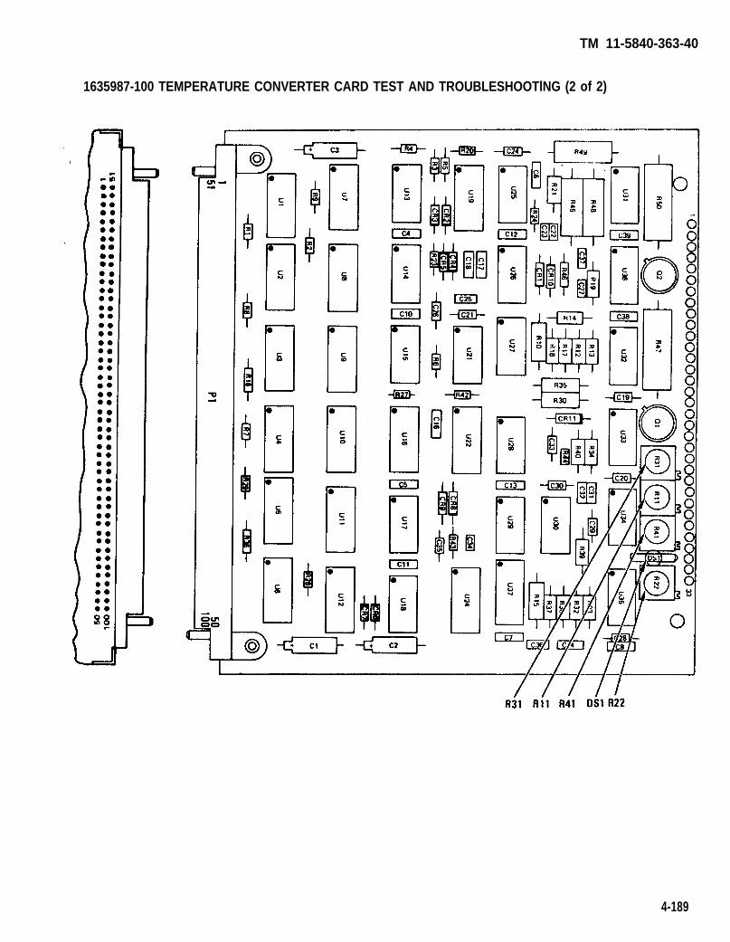
TM 11-5840-363-40
1635987-100 TEMPERATURE CONVERTER CARD TEST AND TROUBLESHOOTlNG (2 of 2)
4-189
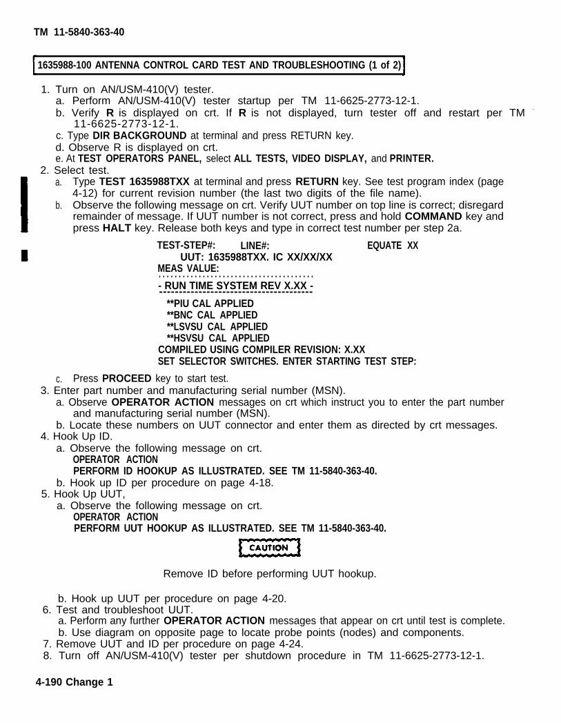
TM 11-5840-363-40
1635988-100 ANTENNA CONTROL CARD TEST AND TROUBLESHOOTING (1 of 2)
1. Turn on AN/USM-410(V) tester.a. Perform AN/USM-410(V) tester startup per TM 11-6625-2773-12-1.b. Verify R is displayed on crt. If R is not displayed, turn tester off and restart per TM -
11-6625-2773-12-1.c. Type DIR BACKGROUND at terminal and press RETURN key.d. Observe R is displayed on crt.e. At TEST OPERATORS PANEL, select ALL TESTS, VIDEO DISPLAY, and PRINTER.
2. Select test.a.
b.
c.
Type TEST 1635988TXX at terminal and press RETURN key. See test program index (page4-12) for current revision number (the last two digits of the file name).Observe the following message on crt. Verify UUT number on top line is correct; disregardremainder of message. If UUT number is not correct, press and hold COMMAND key andpress HALT key. Release both keys and type in correct test number per step 2a.
TEST-STEP#: LINE#: EQUATE XXUUT: 1635988TXX. IC XX/XX/XX
MEAS VALUE:. . . . . . . . . . . . . . . . . . . . . . . . . . . . . . . . . . . . . . .- RUN TIME SYSTEM REV X.XX ----------------------------------------
**PIU CAL APPLIED**BNC CAL APPLIED**LSVSU CAL APPLIED**HSVSU CAL APPLIED
COMPILED USING COMPILER REVISION: X.XXSET SELECTOR SWITCHES. ENTER STARTING TEST STEP:
Press PROCEED key to start test.3. Enter part number and manufacturing serial number (MSN).
a. Observe OPERATOR ACTION messages on crt which instruct you to enter the part numberand manufacturing serial number (MSN).
b. Locate these numbers on UUT connector and enter them as directed by crt messages.4. Hook Up ID.
a. Observe the following message on crt.OPERATOR ACTIONPERFORM ID HOOKUP AS ILLUSTRATED. SEE TM 11-5840-363-40.
b. Hook up ID per procedure on page 4-18.5. Hook Up UUT,
a. Observe the following message on crt.OPERATOR ACTIONPERFORM UUT HOOKUP AS ILLUSTRATED. SEE TM 11-5840-363-40.
Remove ID before performing UUT hookup.
b. Hook up UUT per procedure on page 4-20.6. Test and troubleshoot UUT.
a. Perform any further OPERATOR ACTION messages that appear on crt until test is complete.b. Use diagram on opposite page to locate probe points (nodes) and components.
7. Remove UUT and ID per procedure on page 4-24.8. Turn off AN/USM-410(V) tester per shutdown procedure in TM 11-6625-2773-12-1.
4-190 Change 1

TM 11-5840-363-40
1635988-100 ANTENNA CONTROL CARD TEST AND TROUBLESHOOTING (2 of 2)
4-191

TM 11-5840-363-40
1635990-100 TRIGGER REFRAME CARD TEST AND TROUBLESHOOTlNG (1 of 2)
1. Turn on AN/USM-410(V) tester.a. Perform AN/USM-410(V) tester startup per TM 11-6625-2773-12-1.b. Verify R is displayed on crt. If R is not displayed, turn tester off and restart per TM
11-6625-2773-12-1.c. Type DIR BACKGROUND at terminal and press RETURN key.d. Observe R is displayed on crt.e. At TEST OPERATORS PANEL, select ALL TESTS, VIDEO DISPLAY, and PRINTER.
2. Select test.a. Type TEST 1635990TXX at terminal and press RETURN key. See test program index (page
4-12) for current revision number (the last two digits of the file name).b. Observe the following message on crt. Verify UUT number on top line is correct; disregard.
remainder of message. If UUT number is not correct, press and hold COMMAND key andpress HALT key. Release both keys and type in correct test number per step 2a.
TEST-STEP#: LINE#: EQUATE XXUUT: 1635990TXX. IC XX/XX/XX
MEAS VALUE:. . . . . . . . . . . . . . . . . . . . . . . . . . . . . . . . . . . . . . .- RUN TIME SYSTEM REV X.XX ----------------------------------------
** PIU CAL APPLIED** BNC CAL APPLIED** LSVSU CAL APPLIED** HSVSU CAL APPLIED
COMPILED USING COMPILER REVISION: X.XXSET SELECTOR SWITCHES. ENTER STARTING TEST STEP:
c. Press PROCEED key to start test.3. Enter part number and manufacturing serial number (MSN).
a. Observe OPERATOR ACTION messages on crt which instruct you to enter the part numberand manufacturing serial number (MSN).
b. Locate these numbers on UUT connector and enter them as directed by crt messages.4. Hook Up ID.
a. Observe the following message on crt.OPERATOR ACTIONPERFORM ID HOOKUP AS ILLUSTRATED. SEE TM 11-5840-363-40.
b. Hook up ID per procedure on page 4-18.5. Hook Up UUT.
a. Observe the following message on crt.OPERATOR ACTIONPERFORM UUT HOOKUP AS ILLUSTRATED. SEE TM 11-5840-363-40.
Remove ID before performing UUT hookup.
b. Hook up UUT per procedure on page 4-20.6. Test and troubleshoot UUT.
a. Perform any further OPERATOR ACTION messages that appear on crt until test is complete.b. Use diagram on opposite page to locate probe points (nodes) and components.
7. Remove UUT and ID per procedure on page 4-24.8. Turn off AN/USM-410(V) tester per shutdown procedure in TM 11-6625-2773-12-1.
4-192 Change 1

TM 11-5840-363-40
1635990-100 TRIGGER REFRAME CARD TEST AND TROUBLESHOOTING (2 of 2)
4-193

TM 11-5840-363-40
1642175-100 MEMORY FUNCTION INTERFACE CARD TEST AND TROUBLESHOOTlNG (1 of 2)
1. Turn on AN/USM-410(V) tester.a. Perform AN/USM-410(V) tester startup per TM 11-6625-2773-12-1.b. Verify R is displayed on crt. If R is not displayed, turn tester off and restart per TM
11-6625-2773-12-1.c. Type DIR BACKGROUND at terminal and press RETURN key.d. Observe R is displayed on crt.e. At TEST OPERATORS PANEL, select ALL TESTS, VIDEO DISPLAY, and PRINTER.
2. Select test.a. Type TEST 1642175TXX at terminal and press RETURN key. See test program index (page
4-12) for current revision number (the last two digits of the file name).b. Observe the following message on crt. Verify UUT number on top line is correct; disregard
remainder of message. If UUT number is not correct, press and hold COMMAND key andpress HALT key. Release both keys and type in correct test number per step 2a.
TEST-STEP#: LINE#: EQUATE XXUUT: 1642175TXX. IC XX/XX/XX
MEAS VALUE:. . . . . . . . . . . . . . . . . . . . . . . . . . . . . . . . . . . . . . .- RUN TIME SYSTEM REV X.XX ----------------------------------------
**PIU CAL APPLIED**BNC CAL APPLIED**LSVSU CAL APPLIED**HSVSU CAL APPLIED
COMPILED USING COMPILER REVISION: X.XXSET SELECTOR SWITCHES. ENTER STARTING TEST STEP:
c. Press PROCEED key to start test.3. Enter part number and manufacturing serial number (MSN).
a. Observe OPERATOR ACTION messages on crt which instruct you to enter the part numberand manufacturing serial number (MSN).
b. Locate these numbers on UUT connector and enter them as directed by crt messages.4. Hook Up ID.
a. Observe the following message on crt.OPERATOR ACTIONPERFORM ID HOOKUP AS ILLUSTRATED. SEE TM 11-5840-383-40.
b. Hook up ID per procedure on page 4-18.5. Hook Up UUT.
a. Observe the following message on crt.OPERATOR ACTIONPERFORM UUT HOOKUP AS ILLUSTRATED. SEE TM 11-5840-363-40.
Remove ID before performing UUT hookup.
b. Hook up UUT per procedure on page 4-20.6. Test and troubleshoot UUT.
a. perform any further OPERATOR ACTION messages that appear on crt until test is complete.b. use diagram on opposite page to locate probe points (nodes) and components.
7. Remove UUT and ID per procedure on page 4-24.8. Turn off AN/USM-410(V) tester per shutdown procedure in TM 11-6625-2773-12-1.
4-194 Change 1

TM 11-5840-363-40
1642175-100 MEMORY FUNCTION lNTERFACE CARD TEST AND TROUBLESHOOTING (2 of 2)
4-195

TM 11-5840-363-40
1642176-100 ARITHMETIC REGISTER CARD TEST AND TROUBLESHOOTING (1 of 2)
1. Turn on AN/USM-410(V) tester.a. Perform AN/USM-410(V) tester startup per TM 11-6625-2773-12-1.b. Verify R is displayed on crt. If R is not displayed, turn tester off and restart per TM
11-6625-2773-12-1.c. Type DIR BACKGROUND at terminal and press RETURN key.d. Observe R is displayed on crt.e. At TEST OPERATORS PANEL, select ALL TESTS, VIDEO DISPLAY, and PRINTER.
2. Select test.a. Type TEST 1642176TXX at terminal and press RETURN key. See test program index (page
4-12) for current revision number (the last two digits of the file name).b. Observe the following message on crt. Verify UUT number on top line is correct; disregard
remainder of message. If UUT number is not correct, press and hold COMMAND key andpress HALT key. Release both keys and type in correct test number per step 2a.
TEST-STEP#: LINE#: EQUATE XXUUT: 1642176TXX. IC XX/XX/XX
MEAS VALUE:. . . . . . . . . . . . . . . . . . . . . . . . . . . . . . . . . . . . . . .- RUN TIME SYSTEM REV X.XX -. . . . . . . . . . . . . . . . . . . . . . . . . . . . . . . . . . . . . . .
** PIU CAL APPLIED** BNC CAL APPLIED** LSVSU CAL APPLIED** HSVSU CAL APPLIED
COMPILED USING COMPILER REVISION: X.XXSET SELECTOR SWITCHES. ENTER STARTING TEST STEP:
c. Press PROCEED key to start test.3. Enter part number and manufacturing serial number (MSN).
a. Observe OPERATOR ACTION messages on crt which instruct you to enter the part numberand manufacturing serial number (MSN).
b. Locate these numbers on UUT connector and enter them as directed by crt messages.4. Hook Up ID.
a. Observe the following message on crt.OPERATOR ACTIONPERFORM ID HOOKUP AS ILLUSTRATED. SEE TM 11-5840-363-40.
b. Hook up ID per procedure on page 4-18.5. Hook Up UUT.
a. Observe the following message on crt.OPERATOR ACTIONPERFORM UUT HOOKUP AS ILLUSTRATED. SEE TM 11-5840-363-40.
Remove ID before performing UUT hookup.
b. Hook up UUT per procedure on page 4-20.6. Test and troubleshoot UUT.
a. Perform any further OPERATOR ACTION messages that appear on crt until test is complete.b. Use diagram on opposite page to locate probe points (nodes) and components.
7. Remove UUT and ID per procedure on page 4-24.8. Turn off AN/USM-410(V) tester per shutdown procedure in TM 11-6625-2773-12-1.
4-196 Change 1

TM 11-5840-363-40
1642176-100 ARITHMETIC REGISTER CARD TEST AND TROUBLESHOOTING (2 of 2)
4-197

1642177-100 MICROSEQUENCER CARD TEST AND TROUBLESHOOTING (1 of 2)
1. Turn on AN/USM-410(V) tester.a. Perform AN/USM-410(V) tester startup per TM 11-6625-2773-12-1.b. Verify R is displayed on crt. If R is not displayed, turn tester off and restart per TM
11-6625-2773-12-1.c. Type DIR BACKGROUND at terminal and press RETURN key.d. Observe R is displayed on crt.e. At TEST OPERATORS PANEL, select ALL TESTS, VIDEO DISPLAY, and PRINTER.
2. Select test.a. Type TEST 1642177TXX at terminal and press RETURN key. See test program index (page
4-12) for current revision number (the last two digits of the file name).b. Observe the following message on crt. Verify UUT number on top line is correct; disregard
remainder of message. If UUT number is not correct, press and hold COMMAND key andpress HALT key. Release both keys and type in correct test number per step 2a.
TEST-STEP#: LINE#: EQUATE XXUUT: 1642177TXX. IC XX/XX/XX
MEAS VALUE:. . . . . . . . . . . . . . . . . . . . . . . . . . . . . . . . . . . . . . .- RUN TIME SYSTEM REV X.XX -. . . . . . . . . . . . . . . . . . . . . . . . . . . . . . . . . . . . . . .
** PIU CAL APPLIED** BNC CAL APPLIED** LSVSU CAL APPLIED** HSVSU CAL APPLIED
COMPILED USING COMPILER REVISION: X.XXSET SELECTOR SWITCHES. ENTER STARTING TEST STEP:
c. Press PROCEED key to start test.3. Enter part number and manufacturing serial number (MSN).
a. Observe OPERATOR ACTION messages on crt which instruct you to enter the part numberand manufacturing serial number (MSN).
b. Locate these numbers on UUT connector and enter them as directed by crt messages.4. Hook Up ID.
a. Observe the following message on crt.OPERATOR ACTIONPERFORM ID HOOKUP AS ILLUSTRATED. SEE TM 11-5840-363-40.
b. Hook up ID per procedure on page 4-18.5. Hook Up UUT.
a. Observe the following message on crt.OPERATOR ACTIONPERFORM UUT HOOKUP AS ILLUSTRATED. SEE TM 11-5840-363-40.
Remove ID before performing UUT hookup.
b. Hook up UUT per procedure on page 4-20.6. Test and troubleshoot UUT.
b. Use diagram on opposite page to locate probe points (nodes) and components.7. Remove UUT and ID per procedure on page 4-24.8. Turn off AN/USM-410(V) tester per shutdown procedure in TM 11-6625-2773-12-1.
4-198 Change 1
TM 11-5840-363-40
a. Perform any further OPERATOR ACTION messages that appear on crt until test is complete.
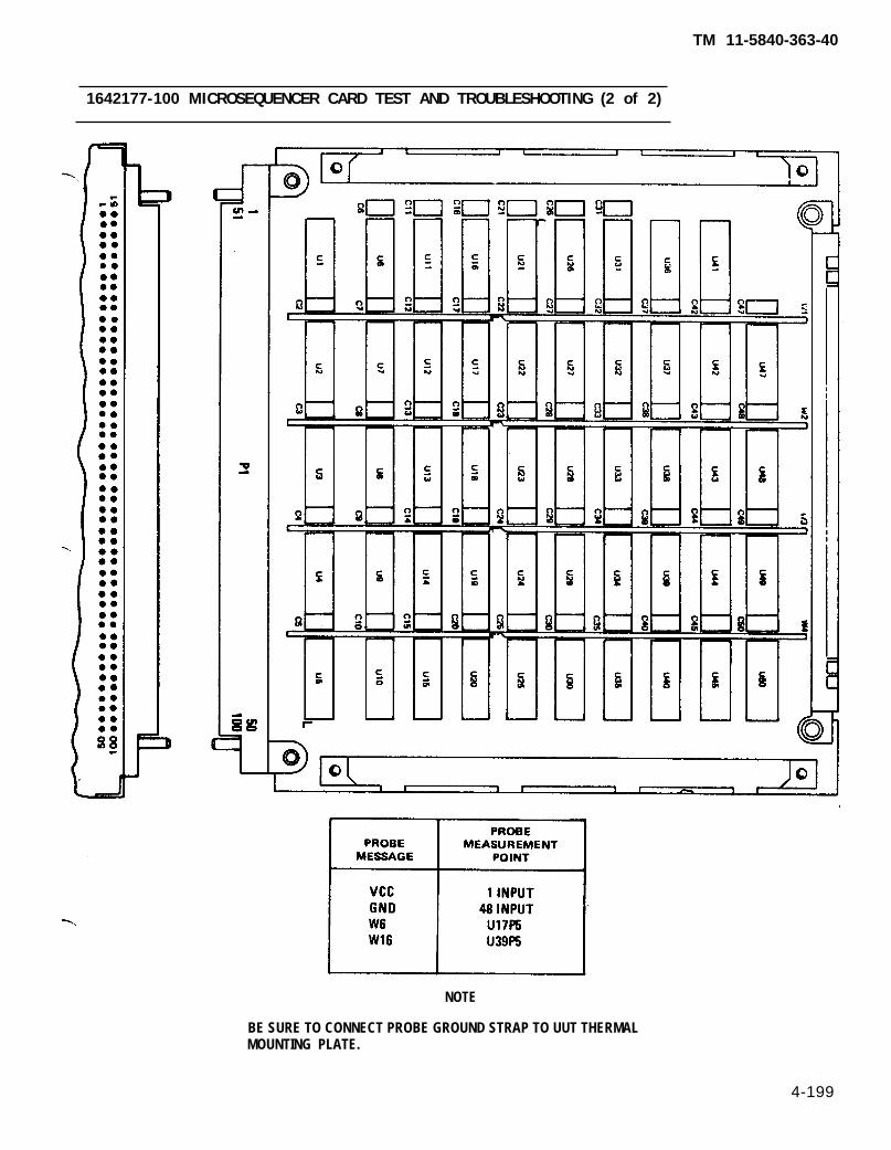
TM 11-5840-363-40
1642177-100 MICROSEQUENCER CARD TEST AND TROUBLESHOOTING (2 of 2)
NOTE
BE SURE TO CONNECT PROBE GROUND STRAP TO UUT THERMALMOUNTING PLATE.
4-199

TM 11-5840-363-40
1642178-100 READ ONLY MEMORY 1 CARD TEST AND TROUBLESHOOTING (1 of 2)
1. Turn on AN/USM-410(V) tester.a. Perform AN/USM-410(V) tester startup per TM 11-6625-2773-12-1.b. Verify R is displayed on crt. If R is not displayed, turn tester off and restart per TM
11-6625-2773-12-1.c. Type DIR BACKGROUND at terminal and press RETURN key.d. Observe R is displayed on crt.e. At TEST OPERATORS PANEL, select ALL TESTS, VIDEO DISPLAY, and PRINTER.
2. Select test.a. Type TEST 1642178TXX at terminal and press RETURN key. See test program index (page
4-12) for current revision number (the last two digits of the file name).b. Observe the following message on crt. Verify UUT number on top fine is correct; disregard
remainder of message. If UUT number is not correct, press and hold COMMAND key andpress HALT key. Release both keys and type in correct test number per step 2a.
TEST- STEP#: LINE#: EQUATE XXUUT: 1642178TXX. IC XX/XX/XX
MEAS VALUE:. . . . . . . . . . . . . . . . . . . . . . . . . . . . . . . . . . . . . . .- RUN TIME SYSTEM REV X.XX ----------------------------------------
** PIU CAL APPLIED** BNC CAL APPLIED,** LSVSU CAL APPLIED** HSVSU CAL APPLIED
COMPILED USING COMPILER REVISION: X.XXSET SELECTOR SWITCHES. ENTER STARTING TEST STEP:
c. Press PROCEED key to start test.3. Enter part number and manufacturing serial number (MSN).
a. Observe OPERATOR ACTION messages on crt which instruct you to enter the part numberand manufacturing serial number (MSN).
b. Locate these numbers on UUT connector and enter them as directed by crt messages.4. Hook up ID.
a. Observe the following message on crt.OPERATOR ACTIONPERFORM ID HOOKUP AS ILLUSTRATED. SEE TM 11-5840-363-40.
b. Hook up ID per procedure on page 4-18.5. Hook Up UUT.
a. Observe the following message on crt.OPERATOR ACTIONPERFORM UUT HOOKUP AS ILLUSTRATED. SEE TM 11-5840-363-40.
Remove ID before performing UUT hookup.
b. Hook up UUT per procedure on page 4-20.6. Test and troubleshoot UUT.
a. Perform any further OPERATOR ACTION messages that appear on crt until test is complete.b. Use diagram on opposite page to locate probe points (nodes) and components.
7. Remove UUT and ID per procedure on page 4-24.8. Turn off AN/USM-410(V) tester per shutdown procedure in TM 11-6625-2773-12-1.
4-200 Change 1
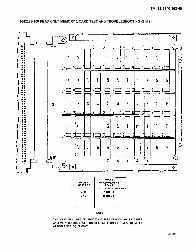
TM 11-5840-363-40
1642178-100 READ ONLY MEMORY 1 CARD TEST AND TROUBLESHOOTING (2 of 2)
NOTE
THIS CARD REQUIRES AN ADDITIONAL TEST CLIP OR POWER CABLEASSEMBLY DURING TEST. CONSULT TABLE ON PAGE 4-22 TO SELECTAPPROPRIATE EQUIPMENT.
4-201
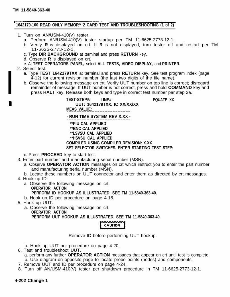
1642179-100 READ ONLY MEMORY 2 CARD TEST AND TROUBLESHOOTING (1 of 2)
1. Turn on AN/USM-410(V) tester.a. Perform AN/USM-410(V) tester startup per TM 11-6625-2773-12-1.b. Verify R is displayed on crt. If R is not displayed, turn tester off and restart per TM
11-6625-2773-12-1.c. Type DIR BACKGROUND at terminal and press RETURN key.d. Observe R is displayed on crt.e. At TEST OPERATORS PANEL, select ALL TESTS, VIDEO DISPLAY, and PRINTER.
2. Select test.a. Type TEST 1642179TXX at terminal and press RETURN key. See test program index (page
4-12) for current revision number (the last two digits of the file name).b. Observe the following message on crt. Verify UUT number on top line is correct; disregard
remainder of message. If UUT number is not correct, press and hold COMMAND key andpress HALT key. Release both keys and type in correct test number par step 2a.
TEST-STEP#: LINE#: EQUATE XXUUT: 1642179TXX. IC XX/XX/XX
MEAS VALUE:---------------------------------------- RUN TIME SYSTEM REV X.XX ----------------------------------------
**PIU CAL APPLIED**BNC CAL APPLIED**LSVSU CAL APPLIED**HSVSU CAL APPLIED
COMPILED USING COMPILER REVISION: X.XXSET SELECTOR SWITCHES. ENTER STARTING TEST STEP:
c. Press PROCEED key to start test.3. Enter part number and manufacturing serial number (MSN).
a. Observe OPERATOR ACTION messages on crt which instruct you to enter the part numberand manufacturing serial number (MSN).
b. Locate these numbers on UUT connector and enter them as directed by crt messages.4. Hook up ID.
a. Observe the following message on crt.OPERATOR ACTIONPERFORM ID HOOKUP AS ILLUSTRATED. SEE TM 11-5840-363-40.
b. Hook up ID per procedure on page 4-18.5. Hook up UUT.
a. Observe the following message on crt.OPERATOR ACTIONPERFORM UUT HOOKUP AS ILLUSTRATED. SEE TM 11-5840-363-40.
Remove ID before performing UUT hookup.
b. Hook up UUT per procedure on page 4-20.6. Test and troubleshoot UUT.
a. perform any further OPERATOR ACTION messages that appear on crt until test is complete.b. Use diagram on opposite page to locate probe points (nodes) and components.
7. Remove UUT and ID per procedure on page 4-24.8. Turn off AN/USM-410(V) tester per shutdown procedure in TM 11-6625-2773-12-1.
4-202 Change 1
TM 11-5840-363-40
TM 11-5840-363-40
1642179-100 READ ONLY MEMORY 2 CARD TEST AND TROUBLESHOOTING (2 of 2)
NOTE
THIS CARD REQUIRES AN ADDITIONAL TEST CLIP OR POWER CABLEASSEMBLY DURING TEST. CONSULT TABLE ON PAGE 4-22 TO SELECTAPPROPRlATE EQUIPMENT.
4-203

TM 11-5840-363-40
1642180-100 ONLY MEMORY 3 CARD TEST AND TROUBLESHOOTING (1 of 2)
1. Turn on AN/USM-410(V) tester.a. Perform AN/USM-410(V) tester startup per TM 11-6625-2773-12-1.b. Verify R is displayed on crt. If R is not displayed, turn tester off and restart per TM
11-6625-2773-12-1.c. Type DIR BACKGROUND at terminal and press RETURN key.d. Observe R is displayed on crt.e. At TEST OPERATORS PANEL, select ALL TESTS, VIDEO DISPLAY, and PRINTER.
2. Select test.a. Type TEST 1842180TXX at terminal and press RETURN key. See test program index (page
4-12) for current revision number (the last two digits of the file name).b. Observe the following message on crt. Verify UUT number on top line is correct; disregard
remainder of message. If UUT number is not correct, press and hold COMMAND key andpress HALT key. Release both keys and type in correct test number per step 2a.
TEST-STEP#: LINE#: EQUATE XXUUT: 1642180TXX. IC XX/XX/XX
MEAS VALUE:---------------------------------------- RUN TIME SYSTEM REV X.XX ----------------------------------------
** PIU CAL APPLIED** BNC CAL APPLIED** LSVSU CAL APPLIED** HSVSU CAL APPLIED
COMPlLED USING COMPILER REVISION: X.XXSET SELECTOR SWITCHES. ENTER STARTING TEST STEP:
c. Press PROCEED key to start test.3. Enter part number and manufacturing serial number (MSN).
a. Observe OPERATOR ACTION messages on crt which instruct you to enter the part numberend manufacturing serial number (MSN).
b. Locate these numbers on UUT connector and enter them as directed by crt messages.4. Hook up ID.
a. Observe the following message on crt.OPERATOR ACTIONPERFORM ID HOOKUP AS ILLUSTRATED. SEE TM 11-5840-363-40.
b. Hook up ID per procedure on page 4-18.5. Hook up UUT.
a. Observe the following message on crt.OPERATOR ACTIONPERFORM UUT HOOKUP AS ILLUSTRATED. SEE TM 11-5840-303-40.
Remove ID before performing UUT hookup.
b. Hook up UUT per procedure on page 4-20.6. Test and troubleshoot UUT.
a. Perform any further OPERATOR ACTION messages that appear on crt until test is complete.b. Use diagram on opposite page to locate probe points (nodes) and components.
7. Remove UUT and ID per procedure on page 4-24.8. Turn off AN/USM-410(V) tester per shutdown procedure in TM 11-6625-2773-12-1.
4-204 Change 1

TM 11-5840-363-40
THIS CARD REQUIRES AN ADDITIONAL TEST CLIP OR POWER CABLEASSEMBLY DURING TEST. CONSULT TABLE ON PAGE 4-22 TO SELECTAPPROPRIATE EQUIPMENT.
1642180-100 READ ONLY MEMORY 3 CARD TEST AND TROUBLESHOOTING (2 of 2)
4 - 2 0 5

TM 11-5840-363-40
1642181-100 EXTERNAL REGISTER CONTROL CARD TEST AND TROUBLESHOOTING (1 of 2)
1. Turn on AN/USM-410(V) tester.a. Perform AN/USM-410(V) tester startup per TM 11-6625-2773-12-1.b. Verify R is displayed on crt. If R is not displayed, turn tester off and restart per TM
11-6625-2773-12-1.c. Type DIR BACKGROUND at terminal and press RETURN key.d. Observe R is displayed on crt.e. At TEST OPERATORS PANEL, select ALL TESTS, VIDEO DISPLAY, and PRINTER.
2. Select test.a. Type TEST 1642181TXX at terminal and press RETURN key. See test program index (page
4-12) for current revision number (the last two digits of the file name).b. Observe the following message on crt. Verify UUT number on top line is correct; disregard
remainder of message. If UUT number is not correct, press and hold COMMAND key andpress HALT key. Release both keys and type in correct test number per step 2a.
TEST-STEP#: LINE#: EQUATE XXUUT: 1642181TXX. IC XX/XX/XX
MEAS VALUE:. . . . . . . . . . . . . . . . . . . . . . . . . . . . . . . . . . . . . . .- RUN TIME SYSTEM REV X.XX ----------------------------------------
**PIU CAL APPLIED**BNC CAL APPLIED**LSVSU CAL APPLIED**HSVSU CAL APPLIED
COMPILED USING COMPILER REVISION: X.XXSET SELECTOR SWITCHES. ENTER STARTING TEST STEP:
c. Press PROCEED key to start test.3. Enter part number and manufacturing serial number (MSN).
a. Observe OPERATOR ACTION messages on crt which instruct you to enter the part numberand manufacturing serial number (MSN).
b. Locate these numbers on UUT connector and enter them as directed by crt messages.4. Hook up ID.
a. Observe the following message on crt.OPERATOR ACTIONPERFORM ID HOOKUP AS ILLUSTRATED. SEE TM 11-5840-363-40.
b. Hook up ID per procedure on page 4-18.5. Hook up UUT.
a. Observe the following message on crt.OPERATOR ACTIONPERFORM UUT HOOKUP AS ILLUSTRATED. SEE TM 11-5840-363-40.
Remove ID before performing UUT hookup.
b. Hook up UUT per procedure on page 4-20.6. Test and troubleshoot UUT.
a. Perform any further OPERATOR ACTION messages that appear on crt until test is complete. b. Use diagram on opposite page to locate probe points (nodes) and components.
7. Remove UUT and ID per procedure on page 4-24.8. Turn off AN/USM-410(V) tester per shutdown procedure in TM 11-6625-2773-12-1.
4-206 Change 1

TM 11-5840-363-40
1642181-100 EXTERNAL REGISTER CONTROL CARD TEST AND TROUBLESHOOTING (2 of 2)
Change 1 4-207(pages 4-208 and 4-209 deleted)

1642183-100 EXTERNAL MULTIPLEX REGISTER CARD TEST AND TROUBLESHOOTING (1 of 2),
1. Turn on AN/USM-410(V) tester.a. Perform AN/USM-410(V) tester startup per TM 11-6625-2773-12-1.b. Verify R is displayed on crt. If R is not displayed, turn tester off and restart per TM
11-6625-2773-12-1.c. Type DIR BACKGROUND at terminal and press RETURN key.d. Observe R is displayed on crt.e. At TEST OPERATORS PANEL, select ALL TESTS, VIDEO DISPLAY, and PRINTER.
2. Select test.a. Type TEST 1642183TXX at terminal and press RETURN key. See test program index (page
4-12) for current revision number (the last two digits of the file name).b. Observe the following message on crt. Verify UUT number on top line is correct; disregard
remainder of message. If UUT number is not correct, press and hold COMMAND key andpress HALT key. Release both keys and type in correct test number per step 2a.
TEST-STEP#: LINE#: EQUATE XXUUT: 1642183TXX. IC XX/XX/XX
MEAS VALUE:. . . . . . . . . . . . . . . . . . . . . . . . . . . . . . . . . . . . . . .- RUN TIME SYSTEM REV X.XX -. . . . . . . . . . . . . . . . . . . . . . . . . . . . . . . . . . . . . . .
**PIU CAL APPLIED**BNC CAL APPLIED**LSVSU CAL APPLIED**HSVSU CAL APPLIED
COMPILED USING COMPILER REVISION: X.XXSET SELECTOR SWITCHES. ENTER STARTING TEST STEP:
c. Press PROCEED key to start test.3. Enter part number and manufacturing serial number (MSN).
a. Observe OPERATOR ACTION messages on crt which instruct you to enter the part numberand manufacturing serial number (MSN).
b. Locate these numbers on UUT connector and enter them as directed by crt messages.4. Hook up ID.
a. Observe the following message on crt.OPERATOR ACTIONPERFORM ID HOOKUP AS ILLUSTRATED. SEE TM 11-5840-363-40.
b. Hook up ID per procedure on page 4-18.5. Hook up UUT.
a. Observe the following message on crt.OPERATOR ACTIONPERFORM UUT HOOKUP AS ILLUSTRATED. SEE TM 11-5840-363-40.
Remove ID before performing UUT hookup.
b. Hook up UUT per procedure on page 4-20.6. Test and troubleshoot UUT.
a. Perform any further OPERATOR ACTION messages that appear on crt until test is complete. b. Use diagram on opposite page to locate probe points (nodes) and components.
7. Remove UUT and ID per procedure on page 4-24.8. Turn off AN/USM-410(V) tester per shutdown procedure in TM 11-6625-2773-12-1.
4-210 Change 1
TM 11-5840-363-40

TM 11-5840-363-40
1642183-100 EXTERNAL MULTIPLEX REGISTER CARD TEST AND TROUBLESHOOTING (2 of 2)
4-211

TM 11-5840-363-40
1642184-100 EXTERNAL CONTROL CARD TEST AND TROUBLESHOOTING (1 of 2)
1. Turn on AN/USM-410(V) tester.a. Perform AN/USM-410(V) tester startup per TM 11-6625-2773-12-1.b. Verify R is displayed on crt. If R is not displayed, turn tester off and restart per TM
11-6625-2773-12-1.c. Type DIR BACKGROUND at terminal and press RETURN key.d. Observe R is displayed on crt.e. At TEST OPERATORS PANEL, select ALL TESTS, VIDEO DISPLAY, and PRINTER.
2. Select test.a. Type TEST 1642184TXX at terminal and press RETURN key. Seetest program index (page
4-12) for current revision number (the last two digits of the file name).b. Observe the following message on crt. Verify UUT number on top line is correct; disregard
remainder of message. If UUT number is not correct, press and hold COMMAND key andpress HALT key. Release both keys and type in correct test number per step 2a.
TEST-STEP#: LINE#: EQUATE XXUUT: 1642184TXX. IC XX/XX/XX
MEAS VALUE:---------------------------------------- RUN TIME SYSTEM REV X.XX ----------------------------------------
**PIU CAL APPLIED**BNC CAL APPLIED**LSVSU CAL APPLIED**HSVSU CAL APPLIED
COMPILED USING COMPILER REVISION: X.XXSET SELECTOR SWITCHES. ENTER STARTING TEST STEP:
c. Press PROCEED key to start test.3. Enter part number and manufacturing serial number (MSN).
a. Observe OPERATOR ACTION messages on crt which instruct you to enter the part numberand manufacturing serial number (MSN).
b. Locate these numbers on UUT connector and enter them as directed by crt messages.4. Hook up ID.
a. Observe the following message on crt.OPERATOR ACTIONPERFORM ID HOOKUP AS ILLUSTRATED. SEE TM 11-5840-363-40.
b. Hook up ID per procedure on page 4-18.5. Hook up UUT.
a. Observe the following message on crt.OPERATOR ACTIONPERFORM UUT HOOKUP AS ILLUSTRATED. SEE TM 11-5840-363-40.
Remove ID before performing UUT hookup.
b. Hook up UUT per procedure on page 4-20.6. Test and troubleshoot UUT.
a. Perform any further OPERATOR ACTION messages that appear on crt until test is complete.b. Use diagram on opposite page to locate probe points (nodes) and components.
7. Remove UUT and ID per procedure on page 4-24.8. Turn off AN/USM-410(V) tester per shutdown procedure in TM 11-6625-2773-12-1.
4-212 Change 1

TM 11-5840-363-40
1642184-100 EXTERNAL CONTROL CARD TEST AND TROUBLESHOOTING (2 of 2)
4-213

TM 11-5840-363-40
1642185-100 PROGRAM STATUS INSTRUCTION DECORERCARD TEST AND TROUBLESHOOTlNG (1 of 2)
1. Turn on AN/USM-410(V) tester.a. Perform AN/USM-410(V) tester startup per TM 11-6625-2773-12-1.b. Verify R is displayed on crt. If R is not displayed, turn tester off and restart per TM
11-6625-2773-12-1.c. Type DIR BACKGROUND at terminal and press RETURN key.d. Observe R is displayed on crt.e. At TEST OPERATORS PANEL, select ALL TESTS, VIDEO DISPLAY, and PRINTER.
2. Select test.a. Type TEST 1642185TXX at terminal and press RETURN key. See test program index (page
4-12) for current revision number (the last two digits of the file name).b. Observe the following message on crt. Verify UUT number on top line is correct; disregard
remainder of message. If UUT number is not correct, press and hold COMMAND key andpress HALT key. Release both keys and type in correct test number per step 2a.
TEST-STEP#: LINE#: EQUATE XXUUT: 1642185TXX. IC XX/XX/XX
MEAS VALUE:. . . . . . . . . . . . . . . . . . . . . . . . . . . . . . . . . . . . . . .- RUN TIME SYSTEM REV X.XX ----------------------------------------
**PIU CAL APPLIED**BNC CAL APPLIED**LSVSU CAL APPLIED**HSVSU CAL APPLIED
COMPILED USING COMPILER REVISION: X.XXSET SELECTOR SWITCHES. ENTER STARTING TEST STEP:
c. Press PROCEED key to start test.3. Enter part number and manufacturing serial number (MSN).
a. Observe OPERATOR ACTION messages on crt which instruct you to enter the part numberand manufacturing serial number (MSN).
b. Locate these numbers on UUT connector and enter them as directed by crt messages.4. Hook up ID.
a. Observe the following message on crt.OPERATOR ACTIONPERFORM ID HOOKUP AS ILLUSTRATED. SEE TM 11-5840-363-40.
b. Hook up ID per procedure on page 4-18.5. Hook up UUT.
a. Observe the following message on crt.OPERATOR ACTIONPERFORM UUT HOOKUP AS ILLUSTRATED. SEE TM 11-5840-363-40.
Remove ID before performing UUT hookup.
b. Hook up UUT per procedure on page 4-20.6. Test and troubleshoot UUT.
a. Perform any further OPERATOR ACTION messages that appear on crt until test is complete.b. Use diagram on opposite page to locate probe points (nodes) and components.
7. Remove UUT and ID per procedure on page 4-24.8. Turn off AN/USM-410(V) tester per shutdown procedure in TM 11-6625-2773-12-1.
4-214 Change 1

TM 11-5840-363-40
1642185-100 PROGRAM STATUS INSTRUCTION DECODERCARD TEST AND TROUBLESHOOTING (2 of 2)
THIS CARD REQUIRES AN ADDITIONAL TEST CLIP OR POWER CABLEASSEMBLY DURING TEST. CONSULT TABLE ON PAGE 4-22 TO SELECTAPPROPRIATE EQUIPMENT.
4-215

1642186-100 FAST MULTIPLIER CORDIC CARD TEST AND TROUBLESHOOTING (1 of 2)
1. Turn on AN/USM-410V) tester.a. Perform AN/USM-410(V) tester startup per TM 11-6625-2773-12-1.b. Verify R is displayed on crt. If R is not displayed, turn tester off and restart per TM
11-6625-2773-12-1.c. Type DIR BACKGROUND at terminal and press RETURN key.d. Observe R is displayed on crt.e. At TEST OPERATORS PANEL, select ALL TESTS, VIDEO DISPLAY, and PRINTER.
2. Select test.a. Type TEST 1642186TXX at terminal and press RETURN key. See test program index (page
4-12) for current revision number (the last two digits of the file name).b. Observe the following message on crt. Verify UUT number on top line is correct; disregard
remainder of message. If UUT number is not correct, press and hold COMMAND key andpress HALT key. Release both keys and type in correct test number per step 2a.
TEST-STEP#: LINE#: EQUATE XXUUT: 1642186TXX. IC XX/XX/XX
MEAS VALUE:---------------------------------------- RUN TIME SYSTEM REV X.XX ----------------------------------------
** PIU CAL APPLIED** BNC CAL APPLIED** LSVSU CAL APPLIED** HSVSU CAL APPLIED
COMPILED USING COMPILER REVISION: X.XXSET SELECTOR SWITCHES. ENTER STARTING TEST STEP:
c. Press PROCEED key to start test.3. Enter part number and manufacturing serial number (MSN).
a. Observe OPERATOR ACTION messages on crt which instruct you to enter the part numberand manufacturing serial number (MSN).
b. Locate these numbers on UUT connector and enter them as directed by crt messages.4. Hook up ID.
a. Observe the following message on crt.OPERATOR ACTIONPERFORM ID HOOKUP AS ILLUSTRATED. SEE TM 11-5840-363-40.
b. Hook up ID per procedure on page 4-18.5. Hook up UUT.
a. Observe the following message on crt.OPERATOR ACTIONPERFORM UUT HOOKUP AS ILLUSTRATED. SEE TM 11-5840-363-40.
Remove ID before performing UUT hookup.
b. Hook up UUT per procedure on page 4-20.6. Test and troubleshoot UUT.
a. Perform any further OPERATOR ACTION messages that appear on crt until test is complete.b. Use diagram on opposite page to locate probe points (nodes) and components.
7. Remove UUT and ID per procedure on page 4-24.8. Turn off AN/USM-410(V) tester per shutdown procedure in TM 11-6625-2773-12-1.
4-216 Change 1
TM 11-5840-363-40
TM 11-5840-363-40
1642186-100 FAST MULTIPLIER CORDIC CARD TEST AND TROUBLESHOOTING (2 of 2)
4 -217

TM 11-5840-363-40
1642187-100 I/O COMMON DATA PATH CARD TEST AND TROUBLESHOOTING (1 of 2)
1. Turn on AN/USM-410(V) tester.a. Perform AN/USM-410(V) tester startup per TM 11-6625-2773-12-1.b. Verify R is displayed on crt. If R is not displayed, turn tester off and restart per TM
11-6625-2773-12-1.c. Type DIR BACKGROUND at terminal and press RETURN key.d. Observe R is displayed on crt.e. At TEST OPERATORS PANEL, select ALL TESTS, VIDEO DISPLAY, and PRINTER.
2. Select test.a. Type TEST 1642187TXX at terminal and press RETURN key. See test program index (page
4-12) for current revision number (the last two digits of the file name).b. Observe the following message on crt. Verify UUT number on top line is correct; disregard
remainder of message. If UUT number is not correct, press and hold COMMAND key andpress HALT key. Release both keys and type in correct test number per step 2a.
TEST-STEP#: LINE#: EQUATE XXUUT: 1642187TXX. IC XX/XX/XX
MEAS VALUE:. . . . . . . . . . . . . . . . . . . . . . . . . . . . . . . . . . . . . . .– RUN TIME SYSTEM REV X.XX –. . . . . . . . . . . . . . . . . . . . . . . . . . . . . . . . . . . . . . .
**PIU CAL APPLIED**BNC CAL APPLIED**LSVSU CAL APPLIED**HSVSU CAL APPLIED
COMPILED USING COMPILER REVISION: X.XXSET SELECTOR SWITCHES. ENTER STARTING TEST STEP:
c. Press PROCEED key to start test.3. Enter part number and manufacturing serial number (MSN).
a. Observe OPERATOR ACTION messages on crt which instruct you to enter the part numberand manufacturing serial number (MSN).
b. Locate these numbers on UUT connector and enter them as directed by crt messages.4. Hook up ID.
a. Observe the following message on crt.OPERATOR ACTIONPERFORM ID HOOKUP AS ILLUSTRATED. SEE TM 11-5840-363-40.
b. Hook up ID per procedure on page 4-18.5. Hook up UUT.
a. Observe the following message on crt.OPERATOR ACTIONPERFORM UUT HOOKUP AS ILLUSTRATED. SEE TM 11-5840-363-40.
Remove ID before performing UUT hookup.
b. Hook up UUT per procedure on page 4-20.6. Test and troubleshoot UUT.
a. Perform any further OPERATOR ACTION messages that appear on crt until test is complete.b. Use diagram on opposite page to locate probe points (nodes) and components.
7. Remove UUT and ID per procedure on page 4-24.8. Turn off AN/USM-410(V) tester per shutdown procedure in TM 11-6625-2773-12-1.
4-218 Change 1

TM 11-5840-363-40
1642187-100 I/O COMMON DATA PATH CARD TEST AND TROUBLESHOOTING (2 of 2)
4-219

TM 11-5840-363-40
1642188-100 I/O COMMON CONTROL CARD TEST AND TROUBLESHOOTING (1 of 2)
1. Turn on AN/USM-410(V) tester.a. Perform AN/USM-410(V) tester startup per TM 11-6625-2773-12-1.b. Verify R is displayed on crt. If R is not displayed, turn tester off and restart per TM
11-6625-2773-12-1.c. Type DIR BACKGROUND at terminal and press RETURN key.d. Observe R is displayed on crt.e. At TEST OPERATORS PANEL, select ALL TESTS, VIDEO DISPLAY, and PRINTER.
2. Select test.a. Type TEST 1642188TXX at terminal and press RETURN key. See test program index (page
4-12) for current revision number (the last two digits of the file name).b. Observe the following message on crt. Verify UUT number on top line is correct; disregard
remainder of message. If UUT number is not correct, press and hold COMMAND key andpress HALT key. Release both keys and type in correct test number per step 2a.
TEST-STEP#: LINE#: EQUATE XXUUT: 1642188TXX. IC XX/XX/XX
MEAS VALUE:---------------------------------------– RUN TIME SYSTEM REV X.XX ----------------------------------------
**PIU CAL APPLIED**BNC CAL APPLIED**LSVSU CAL APPLIED**HSVSU CAL APPLIED
COMPILED USING COMPILER REVISION: X.XXSET SELECTOR SWITCHES. ENTER STARTING TEST STEP:
c. Press PROCEED key to start test.3. Enter part number and manufacturing serial number (MSN).
a. Observe OPERATOR ACTION messages on crt which instruct you to enter the part numberand manufacturing serial number (MSN).
b. Locate these numbers on UUT connector and enter them as directed by crt messages.4. Hook up ID.
a. Observe the following message on crt.OPERATOR ACTIONPERFORM ID HOOKUP AS ILLUSTRATED. SEE TM 11-5840-363-40.
b. Hook up ID per procedure on page 4-18.5. Hook up UUT.
a. Observe the following message on crt.OPERATOR ACTIONPERFORM UUT HOOKUP AS ILLUSTRATED. SEE TM 11-5840-363-40.
Remove ID before performing UUT hookup.
b. Hook up UUT per procedure on page 4-20.6. Test and troubleshoot UUT.
a. Perform any further OPERATOR ACTION messages that appear on crt until test is complete.b. Use diagram on opposite page to locate probe points (nodes) and components.
7. Remove UUT and ID per procedure on page 4-24.8. Turn off AN/USM-410(V) tester per shutdown procedure in TM 11-6625-2773-12-1.
4-220 Change 1

TM 11-5840-363-40
1642188-100 I/O COMMON CONTROL CARD TEST AND TROUBLESHOOTING (2 of 2)
I
4-221

TM 11-5840-363-40
1642189-100 DUAL CHANNEL CONTROL CARD TEST AND TROUBLESHOOTING (1 of 2)
1. Turn on AN USM-410(V) tester.a. Perform AN USM-410(V) tester startup per TM 11-6625-2773-12-1.b. Verify R is displayed on crt. If R is not displayed, turn tester off and restart per
11-6625-2773-12-1,c. Type DIR BACKGROUND at terminal and press RETURN key.d. Observe R is displayed on crt.e. At TEST OPERATORS PANEL, select ALL TESTS, VIDEO DISPLAY, and PRINTER.
2. Select test.a. Type TEST 1642189TXX at terminal and press RETURN key. See test program index (page
4-12) for current revision number (the last two digits of the file name).b. Observe the following message on crt Verify UUT number on top Iine is correct; disregard
remainder of message. If UUT number is not correct, press and hold COMMAND key andpress HALT key Release both keys and type in correct test number per step 2a.
TEST-STEP#: LINE#: EQUATE XXUUT: 1642189TXX. IC XX/XX/XX
MEAS VALUE:. . . . . . . . . . . . . . . . . . . . . . . . . . . . . . . . . . . . . . .- RUN TIME SYSTEM REV X.XX -. . . . . . . . . . . . . . . . . . . . . . . . . . . . . . . . . . . . . . .
**PIU CAL APPLIED**BNC CAL APPLIED**LSVSU CAL APPLIED**HSVSU CAL APPLIED
COMPILED USING COMPILER REVISION: X.XXSET SELECTOR SWITCHES. ENTER STARTING TEST STEP:
c. Press PROCEED key to start test.3. Enter part number and manufacturing serial number (MSN).
a. Observe OPERATOR ACTION messages on crt which instruct you to enter the part numberand manufacturing serial number (MSN).
b. Locate these numbers on UUT connector and enter them as directed by crt messages.4. Hook up ID.
a. Observe the following message on crt.OPERATOR ACTIONPERFORM ID HOOKUP AS ILLUSTRATED. SEE TM 11-5840-363-40.
b. Hook up ID per procedure on page 4-18.5. Hook up UUT.
a. Observe the following message on crt.OPERATOR ACTIONPERFORM UUT HOOKUP AS ILLUSTRATED. SEE TM 11-5840-363-40.
Remove ID before performing UUT hookup.
b. Hook up UUT per procedure on page 4-20.6. Test and troubleshoot UUT.
a. Perform any further OPERATOR ACTION messages that appear on crt until test is completeb. Use diagram on opposite page to locate probe points (nodes) and components.
7. Remove UUT and ID per procedure on page 4-24.8. Turn off AN USM-410(V) tester per shutdown procedure in TM 11-6625-2773-12-1.
4-222 Change 1

TM 11-5840-363-40
1642189-100 DUAL CHANNEL CONTROL CARD TEST AND TROUBLESHOOTING (2 of 2)
4-223

1642190-100 DIAGNOSTIC PANEL INTERFACE CARD TEST AND TROUBLESHOOTING (1 of 2)
1. Turn on AN/USM-410(V) tester.a. Perform AN/USM-410(V) tester startup per TM 11-6625-2773-12-1.b. Verify R is displayed on crt. If R is not displayed, turn tester off and restart per TM
11-6625-2773-12-1.c. Type DIR BACKGROUND at terminal and press RETURN key.d. Observe R is displayed on crt.e. At TEST OPERATORS PANEL, select ALL TESTS, VIDEO DISPLAY, and PRINTER.
2. Select test.a. Type TEST 1642190TXX at terminal and press RETURN key. See test program index (page
4-12) for current revision number (the last two digits of the file name).b. Observe the following message on crt. Verify UUT number on top line is correct; disregard
remainder of message. If UUT number is not correct, press and hold COMMAND key andpress HALT key. Release both keys and type in correct test number per step 2a.
TEST-STEP#: LINE#: EQUATE XXUUT: 1642190TXX. IC XX/XX/XX
MEAS VALUE:---------------------------------------- RUN TIME SYSTEM REV X.XX ----------------------------------------
**PIU CAL APPLIED**BNC CAL APPLIED**LSVSU CAL APPLIED**HSVSU CAL APPLIED
COMPILED USING COMPILER REVISION: X.XXSET SELECTOR SWITCHES. ENTER STARTING TEST STEP:
c. Press PROCEED key to start test.3. Enter part number and manufacturing serial number (MSN).
a. Observe OPERATOR ACTION messages on crt which instruct you to enter the part numberand manufacturing serial number (MSN).
b. Locate these numbers on UUT connector and enter them as directed by crt messages.4. Hook up ID.
a. Observe the following message on crt.OPERATOR ACTIONPERFORM ID HOOKUP AS ILLUSTRATED. SEE TM 11-5840-363-40.
b. Hook up ID per procedure on page 4-18.5. Hook up UUT.
a. Observe the following message on crt.OPERATOR ACTIONPERFORM UUT HOOKUP AS ILLUSTRATED. SEE TM 11-5840-363-40.
Remove ID before performing UUT hookup.
b. Hook up UUT per procedure on page 4-20.6. Test and troubleshoot UUT.
a. Perform any further OPERATOR ACTION messages that appear on crt until test is complete.b. Use diagram on opposite page to locate probe points (nodes) and components.
7. Remove UUT and ID per procedure on page 4-24.8. Turn off AN/USM-410(V) tester per shutdown procedure in TM 11-6625-2773-12-1.
4-224 Change 1
TM 11-5840-363-40

TM 11-5840-363-40
1642190-100 DIAGNOSTIC PANEL INTERFACE CARD TEST AND TROUBLESHOOTING (2 of 2)
4-225

TM 11-5840-363-40
1650873-100 EXTERNAL MULTIPLEX REGISTER CARD TEST AND TROUBLESHOOTING (1 of 2)
1. Turn on AN/USM-410(V) tester.a. Perform AN/USM-410(V) tester startup per TM 11-6625-2773-12-1.b. Verify R is displayed on crt. If R is not displayed, turn tester off and restart per TM
11-6625-2773-12-1.c. Type DIR BACKGROUND at terminal and press RETURN key.d. Observe R is displayed on crt.e. At TEST OPERATORS PANEL, select ALL TESTS, VIDEO DISPLAY, and PRINTER.
2. Select test.a. Type TEST 1650873 TXX at terminal and press RETURN key. See test program index (page
4-12) for current revision number (the last two digits of the file name).b. Observe the following message on crt. Verify UUT number on top line is correct; disregard
remainder of message. If UUT number is not correct, press and hold COMMAND key andpress HALT key. Release both keys and type in correct test number per step 2a.
TEST-STEP#: LINE#: EQUATE XXUUT: 1650873TXX. IC XX/XX/XX
MEAS VALUE:---------------------------------------– RUN TIME SYSTEM REV X.XX ----------------------------------------
**PIU CAL APPLIED**BNC CAL APPLIED**LSVSU CAL APPLIED**HSVSU CAL APPLIED
COMPILED USING COMPILER REVISION: X.XXSET SELECTOR SWITCHES. ENTER STARTING TEST STEP:
c. Press PROCEED key to start test.3. Enter part number and manufacturing serial number (MSN).
a. Observe OPERATOR ACTION messages on crt which instruct you to enter the part numberand manufacturing serial number (MSN).
b. Locate these numbers on UUT connector and enter them as directed by crt messages.4. Hook up ID.
a. Observe the following message on crt.OPERATOR ACTIONPERFORM ID HOOKUP AS ILLUSTRATED. SEE TM 11-5840-363-40.
b. Hook up ID per procedure on page 4-18.5. Hook up UUT.
a. Observe the following message on crt.OPERATOR ACTIONPERFORM UUT HOOKUP AS ILLUSTRATED. SEE TM 11-5840-363-40,
Remove ID before performing UUT hookup.
b. Hook up UUT per procedure on page 4-20.6. Test and troubleshoot UUT.
a. Perform any further OPERATOR ACTION messages that appear on crt until test is complete.b. Use diagram on opposite page to locate probe points (nodes) and components.
7, Remove UUT and ID per procedure on page 4-24.8. Turn off AN/USM-410(V) tester per shutdown procedure in TM 11-6625-2773-12-1.
4-226 Change 1

TM 11-5840-363-40
1650873-100 EXTERNAL MULTIPLEX REGISTER CARD TEST AND TROUBLESHOOTING (2 of 2)
4-227

C5000511 PHASE SHIFT COMPUTER CARD TEST AND TROUBLESHOOTING (1 of 2)
1. Turn on AN/USM-410(V) tester.a. Perform AN/USM-410(V) tester startup per TM 11-6625-2773-12-1.b. Verify R is displayed on crt. If R is not displayed, turn tester off and restart per TM
11-6625-2773-12-1.c. Type DIR BACKGROUND at terminal and press RETURN key.d. Observe R is dispIayed on crt.e. At TEST OPERATORS PANEL, select ALL TESTS, VIDEO DISPLAY, and PRINTER.
2. Select test.a. Type TEST 5000511TX at terminal and press RETURN key. See test program index (page
4-12) for current revision number (the last digit of the file name).b. Observe the following message on crt. Verify UUT number on top line is correct; disregard
remainder of message. If UUT number is not correct, press and hold COMMAND key andpress HALT key. Release both keys and type in correct test number per step 2a.
TEST-STEP#: LINE#: EQUATE XXUUT: 5000511TX. IC XX/XX/XX
MEAS VALUE:---------------------------------------- RUN TIME SYSTEM REV X.XX ----------------------------------------
**PIU CAL APPLIED**BNC CAL APPLIED**LSVSU CAL APPLIED**HSVSU CAL APPLIED
COMPILED USING COMPILER REVISION: X.XXSET SELECTOR SWITCHES. ENTER STARTING TEST STEP:
c. Press PROCEED key to start test.3. Enter part number and manufacturing serial number (MSN).
a. Observe OPERATOR ACTION messages on crt which instruct you to enter the part numberand manufacturing serial number (MSN).
b. Locate these numbers on UUT connector and enter them as directed by crt messages.4. Hook up ID.
a. Observe the following message on crt.OPERATOR ACTIONPERFORM ID HOOKUP AS ILLUSTRATED. SEE TM 11-5840-363-40.
b. Hook up ID per procedure on page 4-18.5. Hook up UUT.
a. Observe the following message on crt.OPERATOR ACTIONPERFORM UUT HOOKUP AS ILLUSTRATED. SEE TM 11-5840-363-40.
Remove ID before performing UUT hookup.
b. Hook up UUT per procedure on page 4-20.6. Test and troubleshoot UUT.
a. Perform any further OPERATOR ACTION messages that appear on crt until test is complete.b. Use diagram on opposite page to locate probe points (nodes) and components.
7. Remove UUT and ID per procedure on page 4-24.8. Turn off AN/USM-410(V) tester per shutdown procedure in TM 11-6625-2773-12-1.
4-228 Change 1
TM 11-5840-363-40

TM 11-5840-363-40
C5000511 PHASE SHIFT COMPUTER~ CARD TEST AND TROUBLESHOOTING (2 Of 2)
4 -229

TM 11-5840-363-40
SM-D-803125 DATA BUS ENCODER CARD TEST AND TROUBLESHOOTING (1 of 2)
1. Turn on AN/USM-410(V) tester.a. Perform AN/USM-410(V) tester startup per TM 11-6625-2773-12-1.b. Verify R is displayed on crt. If R is not displayed, turn tester off and restart per TM
11-6625-2773-12-1.c. Type DIR BACKGROUND at terminal and press RETURN key.d. Observe R is displayed on crt.e. At TEST OPERATORS PANEL, select ALL TESTS, VIDEO DISPLAY, and PRINTER.
2. Select test.a. Type TEST 803125TX at terminal and press RETURN key. See test program index (page
4-12) for current revision number (the last digit of the file name).b. Observe the following message on crt. Verify UUT number on top line is correct; disregard
remainder of message. If UUT number is not correct, press and hold COMMAND key andpress HALT key. Release both keys and type in correct test number per step 2a.
TEST-STEP#: LINE#: EQUATE XXUUT: 803125TX. IC XX/XX/XX
MEAS VALUE:---------------------------------------- RUN TIME SYSTEM REV X.XX ----------------------------------------
**PIU CAL APPLIED**BNC CAL APPLIED**lSVSU CAL APPLIED**HSVSU CAL APPLIED
COMPILED USING COMPILER REVISION: X.XXSET SELECTOR SWITCHES. ENTER STARTING TEST STEP:
c. Press PROCEED key to start test.3. Enter part number and manufacturing serial number (MSN).
a. Observe OPERATOR ACTION messages on crt which instruct you to enter the part numberand manufacturing serial number (MSN).
b. Locate these numbers on UUT connector and enter them as directed by crt messages.4. Hook up ID.
a. Observe the following message on crt.OPERATOR ACTIONPERFORM ID HOOKUP AS ILLUSTRATED, SEE TM 11-5840-363-40.
b. Hook up ID per procedure on page 4-18.5. Hook up UUT.
a. Observe the following message on crt.OPERATOR ACTIONPERFORM UUT HOOKUP AS ILLUSTRATED. SEE TM 11-5840-363-40.
Remove ID before performing UUT hookup.
b. Hook up UUT per procedure on page 4-20.6. Test and troubleshoot UUT.
a. Perform any further OPERATOR ACTION messages that appear on crt until test is complete.b. Use diagram on opposite page to locate probe points (nodes) and components.
7. Remove UUT and ID per procedure on page 4-24.8. Turn off AN/USM-410(V) tester per shutdown procedure in TM 11-6625-2773-12-1.
4-230 Change 1

TM 11-5840-363-40
SM-D-803125 DATA BUS ENCODER CARD TEST AND TROUBLESHOOTING (2 of 2)
4-231

TM 11-5840-363-40
SM-D-803128 DATA BUS DECODER CARD TEST AND TROUBLESHOOTING ( 1 of 2)
1. Turn on AN/USM-410(V) tester.a. Perform AN/USM-410(V) tester startup per TM 11-6625-2773-12-1.b. Verify R is displayed on crt. If R is not displayed, turn tester off and restart per TM
11-6625-2773-12-1.c. Type DIR BACKGROUND at terminal and press RETURN key.d. Observe R is displayed on crt.e . At TEST OPERATORS PANEL, select ALL TESTS, VIDEO DISPLAY, and PRINTER.
2. Select test.a. Type TEST 803128TX at terminal and press RETURN key. See test program index (page
4-12) for current revision number (the last digit of the file name).b. Observe the following message on crt. Verify UUT number on top line is correct; disregard
remainder of message. If UUT number is not correct, press and hold COMMAND key andpress HALT key. Release both keys and type in correct test number per step 2a.
TEST-STEP#: LINE#: EQUATE XXUUT: 803128TX. IC XX/XX/XX
MEAS VALUE:. . . . . . . . . . . . . . . . . . . . . . . . . . . . . . . . . . . . . . .- RUN TIME SYSTEM REV X.XX -. . . . . . . . . . . . . . . . . . . . . . . . . . . . . . . . . . . . . . .
**PIU CAL- APPLIED**BNC CAL APPLIED**LSVSU CAL APPLIED**HSVSU CAL APPLIED
COMPILED USING COMPILER REVISION: X.XXSET SELECTOR SWITCHES. ENTER STARTING TEST STEP:
c. Press PROCEED key to start test.3. Enter part number and manufacturing serial number (MSN).
a. Observe OPERATOR ACTION messages on crt which instruct you to enter the part numberand manufacturing serial number (MSN).
b. Locate these numbers on UUT connector and enter them as directed by crt messages.4. Hook up ID.
a. Observe the following message on crt.OPERATOR ACTIONPERFORM ID HOOKUP AS ILLUSTRATED. SEE TM 11-5840-363-40.
b. Hook up ID per procedure on page 4-18.5. Hook up UUT.
a. Observe the following message on crt.OPERATOR ACTIONPERFORM UUT HOOKUP AS ILLUSTRATED. SEE TM 11-5840-363-40.
Remove ID before performing UUT hookup.
b. Hook up UUT per procedure on page 4-20.8. Test and troubleshoot UUT.
a. Perform any further OPERATOR ACTION messages that appear on crt until test is complete.b. Use diagram on opposite page to locate probe points (nodes) and components.
7. Remove UUT and ID per procedure on page 4-24.8. Turn off AN/USM-410(V) tester per shutdown procedure in TM 11-6625-2773-12-1.
4-232 Change 1

TM 11-5840-363-40
SM-D-803128 DATA BUS DECODER CARD TEST AND TROUBLESHOOTING (2 of 2)
4-233

TM 11-5840-363-40
SM-D-803137 TEMPERATURE CONVERTER CARD TEST AND TROUBLESHOOTiNG (1 of 2)
1. Turn on AN/USM-410(V) tester.a. Perform AN/USM-410(V) tester startup per TM 11-6625-2773-12-1.b. Verify R is displayed on crt. If R is not displayed, turn tester off and restart per TM
11-6625-2773-12-1.c. Type DIR BACKGROUND at terminal and press RETURN key.d. Observe R is displayed on crt.e. At TEST OPERATORS PANEL, select ALL TESTS, VIDEO DISPLAY, and PRINTER.
2. Select test.a. Type TEST 803137TX at terminal and press RETURN key. See test program index (page
4-12) for current revision number (the last digit of the file name).b. Observe the following message on crt. Verify UUT number on top line is correct; disregard
remainder of message. If UUT number is not correct, press and hold COMMAND key andpress HALT key. Release both keys and type in correct test number per step 2a.
TEST-STEP#: LINE#: EQUATE XXUUT: 803137 TX. IC XX/XX/XX
MEAS VALUE:---------------------------------------- RUN TIME SYSTEM REV X.XX ----. ... -.. -.. . -- . --- q ------------------
**PIU CAL APPLIED**BNC CAL APPLIED**LSVSU CAL APPLIED**HSVSU CAL APPLIED
COMPILED USING COMPILER REVISION: X.XXSET SELECTOR SWITCHES. ENTER STARTING TEST STEP:
c. Press PROCEED key to start test.3. Enter part number and manufacturing serial number (MSN).
a. Observe OPERATOR ACTION messages on crt which instruct you to enter the part numberand manufacturing serial number (MSN).
b. Locate these numbers on UUT connector and enter them as directed by crt messages.4, Hook up ID.
a. Observe the following message on crt.OPERATOR ACTIONPERFORM ID HOOKUP AS ILLUSTRATED. SEE TM 11-5840-363-40.
b. Hook up ID per procedure on page 4-18.5. Hook up UUT.
a. Observe the following message on crt.OPERATOR ACTIONPERFORM UUT HOOKUP AS ILLUSTRATED. SEE TM 11-5840-363-40.
Remove ID before performing UUT hookup.
b. Hook up UUT per procedure on page 4-20.6. Test and troubleshoot UUT.
a. Perform any further OPERATOR ACTION messages that appear on crt until test is complete.b. Use diagram on opposite page to locate probe points (nodes) and components.
7. Remove UUT and ID per procedure on page 4-24.8. Turn off AN/USM-410(V) tester per shutdown procedure in TM 11-6625-2773-12-1.
4-234 Change 1

TM 11-5840-363-40
SM-D-803137 TEMPERATURE CONVERTER CARD TEST AND TROUBLESHOOTING (2 of 2)
4-235

SM-D-803140 CLOCK OSCILLATOR CARD TEST AND TROUBLESHOOTING (1 of 2
1. Turn on AN/USM-410(V) tester.a. Perform AN/USM-410(V) tester startup per TM 11-6625-2773-12-1.b. Verify R is displayed on crt. If R is not displayed, turn tester off and restart per TM
11-6625-2773-12-1.c. Type DIR BACKGROUND at erminal and press RETURN key.d. Observe R is displayed on crt.e. At TEST OPERATORS PANEL, select ALL TESTS, VIDEO DISPLAY, and PRINTER.
2. Select test.a.
b.
c.
Type TEST 803140TX at terminal and press RETURN key. See test program index (page4-12) for current revision number (the last digit of the file name).Observe the following message on crt. Verify UUT number on top line is correct; disregardremainder of message. If UUT number is not correct, press and hold COMMAND key andpress HALT key. Release both keys and type in correct test number per step 2a.
TEST-STEP#: LINE#: EQUATE XXUUT: 803140TX. IC XX/XX/XX
MEAS VALUE:---------------------------------------- RUN TIME SYSTEM REV X.XX ----------------------------------------
**PIU CAL APPLIED**BNC CAL APPLIED**LSVSU CAL APPLIED**HSVSU CAL APPLIED
COMPILED USING COMPILER REVISION: X.XXSET SELECTOR SWITCHES. ENTER STARTING TEST STEP:
Press PROCEED key to start test.3. Enter part number and manufacturing serial number (MSN).
a. Observe OPERATOR ACTION messages on crt which instruct you to enter the part numberand manufacturing serial number (MSN).
b. Locate these numbers on UUT connector and enter them as directed by crt messages.4. Hook up ID.
a. Observe the following message on crt.OPERATOR ACTIONPERFORM ID HOOKUP AS ILLUSTRATED. SEE TM 11-5840-363-40.
b. Hook up ID per procedure on page 4-18.5. Hook up UUT.
a. Observe the following message on crt.OPERATOR ACTIONPERFORM UUT HOOKUP AS ILLUSTRATED. SEE TM 11-5840-363-40.
Remove ID before performing UUT hookup.
b. Hook up UUT per procedure on page 4-20.6. Test and troubleshoot UUT.
a. Perform any further OPERATOR ACTION messages that appear on crt until test is complete.b. Use diagram on opposite page to locate probe points (nodes) and components.
7. Remove UUT and ID per procedure on page 4-24. 8. Turn off AN/USM-410(V) tester per shutdown procedure in TM 11-6625-2773-12-1.
4-236 Change 1
TM 11-5840-363-40

TM 11-5840-363-40
SM-D-803140 CLOCK OSCILLATOR CARD TEST AND TROUBLESHOOTING (2 of 2)
4-237

TM 11-5840-363-40
SM-D-803146 TILT SENSOR CARD TEST AND TROUBLESHOOTING (1 of 2)
1. Turn on AN/USM-410(V) tester.a. Perform AN/USM-410(V) tester startup per TM 11-6625-2773-12-1.b. Verify R is displayed on crt. If R is not displayed, turn tester off and restart per TM
11-6625-2773-12-1.c. Type DIR BACKGROUND at terminal and press RETURN key.d. Observe R is displayed on crt.e. At TEST OPERATORS PANEL, select ALL TESTS, VIDEO DISPLAY, and PRINTER.
2. Select test.a. Type TEST 803146TX at terminal and press RETURN key. See test program index (page
4-12) for current revision number (the last digit of the file name).b. Observe the following message on crt. Verify UUT number on top line is correct; disregard
remainder of message. If UUT number is not correct, press and hold COMMAND key andpress HALT key. Release both keys and type in correct test number per step 2a.
TEST-STEP#: LINE#: EQUATE XXUUT: 803146TX. IC XX/XX/XX
MEAS VALUE:---------------------------------------- RUN TIME SYSTEM REV X.XX ----------------------------------------
**PIU CAL APPLIED**BNC CAL APPLIED**LSVSU CAL APPLIED**HSVSU CAL APPLIED
COMPILED USING COMPILER REVISION: X.XXSET SELECTOR SWITCHES. ENTER STARTING TEST STEP:
c. Press PROCEED key to start test.3. Enter part number and manufacturing serial number (MSN).
a. Observe OPERATOR ACTION messages on crt which instruct you to enter the part numberand manufacturing serial number (MSN).
b. Locate these numbers on UUT connector and enter them as directed by crt messages.4. Hook up ID.
a. Observe the following message on crt.OPERATOR ACTIONPERFORM ID HOOKUP AS ILLUSTRATED. SEE TM 11-5840-363-40.
b. Hook up ID per procedure on page 4-18.5. Hook up UUT.
a. Observe the following message on crt.OPERATOR ACTIONPERFORM UUT HOOKUP AS ILLUSTRATED. SEE TM 11-5840-363-40.
Remove ID before performing UUT hookup.
b. Hook up UUT per procedure on page 4-20.6. Test and troubleshoot UUT.
a. Perform any further OPERATOR ACTION messages that appear on crt until test is complete.b. Use diagram on opposite page to locate probe points (nodes) and components.
7. Remove UUT and ID per procedure on page 4-24.8. Turn off AN/USM-410(V) tester per shutdown procedure in TM 11-6625-2773-12-1.
4-238 Change 1

TM 11-5840-363-40
SM-D-803146 TILT SENSOR CARD TEST AND TROUBLESHOOTING (2 of 2)
4-239

TM 11-5840-363-40
SM-D-803152 PHASE SHIFTER DRIVER CARD TEST AND TROUBLESHOOTING (1 of 2)
1. Turn on AN/USM-410(V) tester.a. Perform AN/USM-410(V) tester startup per TM 11-6625-2773-12-1.b. Verify R is displayed on crt. If R is not displayed, turn tester off and restart per TM
11-6625-2773-12-1.c. Type DIR BACKGROUND at terminal and press RETURN key.d. Observe R is displayed on crt.e. At TEST OPERATORS PANEL, select ALL TESTS, VIDEO DISPLAY, and PRINTER.
2. Select test.a. Type TEST 803152TX at terminal and press RETURN key. see test program index (page
4-12) for current revision number (the last digit of the file name).b. Observe the following message on crt. Verify UUT number on top line is correct; disregard
remainder of message. If UUT number is not correct, press and hold COMMAND key andpress HALT key. Release both keys and type in correct test number per step 2a.
TEST-STEP#: LINE#: EQUATE XXUUT: 803152TX. IC XX/XX/XX
MEAS VALUE:---------------------------------------- RUN TIME SYSTEM REV X.XX ----------------------------------------
**PIU CAL APPLIED **BNC CAL APPLIED **LSVSU CAL APPLIED **HSVSU CAL APPLIED
COMPILED USING COMPILER REVISION: X.XXSET SELECTOR SWITCHES. ENTER STARTING TEST STEP:
c. Press PROCEED key to start test.3. Enter part number and manufacturing seria! number (MSN). a. Observe OPERATOR ACTION messages on crt which instruct you to enter the part number
and manufacturing serial number (MSN). b. Locate these numbers on UUT connector and enter them as directed by crt messages.
4. Hook up ID.a. Observe the following message on crt.
OPERATOR ACTIONPERFORM ID HOOKUP AS ILLUSTRATED. SEE TM 11-5840-363-40.
b. Hook up ID per procedure on page 4-18.5. Hook up UUT.
a. Observe the following message on crt.OPERATOR ACTIONPERFORM UUT HOOKUP AS ILLUSTRATED. SEE TM 11-5840-363-40.
Remove ID before performing UUT hookup.
b. Hook up UUT per procedure on page 4-20.6. Test and troubleshoot UUT.
a, Perform any further OPERATOR ACTION messages that appear on crt until test is complete.b. Use diagram on opposite page to locate probe points (nodes) and components.
7. Remove UUT and ID per procedure on page 4-24.8. Turn off AN/USM-410(V) tester per shutdown procedure in TM 11-6625-2773-12-1.
4-240 Change 1

Change 1 4-241
TM 11-5840-363-40
SM-D-803152 PHASE SHIFTER DRIVER CARD TEST AND TROUBLESHOOTING (2 of 2)

TM 11-5840-363-40
SM-D-803161 POWER SUPPLY BITE CARD TEST AND TROUBLESHOOTING (1 of 2)
1. Turn on AN/USM-410(V) tester.a. Perform AN/USM-410(V) tester startup per TM 11-6625-2773-12-1.b. Verify R is displayed on crt. If R is not displayed, turn tester off and restart per TM
11-6625-2773-12-1.e. Type DIR BACKGROUND at terminal and press RETURN key.d. Observe R is displayed on crt.e. At TEST OPERATIONS PANEL, select ALL TESTS, VIDEO DISPLAY, and PRINTER.
2. Select test.a. Type TEST 803161TX at terminal and press RETURN key. See test program index (page
4-12) for current revision number (the last digit of the file name).b. Observe the following message on crt. Verify UUT number on top line is correct; disregard
remainder of message. If UUT number is not correct, press and hold COMMAND key andpress HALT key. Release both keys and type in correct test number per step 2a.
TEST-STEP#: LINE#: EQUATE XXUUT: 803161TX. IC XX/XX/XX
MEAS VALUE:---------------------------------------- RUN TIME SYSTEM REV X.XX -. . . . . . . . . . . . . . . . . . . . . . . . . . . . . . . . . . . . . . .
**PIU CAL APPLIED**BNC CAL APPLIED**LSVSU CAL APPLIED**HSVSU CAL APPLIED
COMPILED USING COMPILER REVISION: X.XXSET SELECTOR SWITCHES. ENTER STARTING TEST STEP:
c. Press PROCEED key to start test.3. Enter part number and manufacturing serial number (MSN).
a. Observe OPERATOR ACTION messages on crt which instruct you to enter the part numberand manufacturing serial number (MSN).
b. Locate these numbers on UUT connector and enter them as directed by crt messages.4. Hook up ID.
a. Observe the following message on crt.OPERATOR ACTIONPERFORM ID HOOKUP AS ILLUSTRATED. SEE TM 11-5840-363-40.
b. Hook up ID per procedure on page 4-18.5. Hook up UUT.
a. Observe the following message on crt.OPERATOR ACTIONPERFORM UUT HOOKUP AS ILLUSTRATED. SEE TM 11-5840-363-40.
Remove ID before performing UUT hookup.
b. Hook up UUT per procedure on page 4-20.6. Test and troubleshoot UUT.
a. Perform any further OPERATOR ACTION messages that appear on crt until test is complete.b. Use diagram on opposite page to locate probe points (nodes) and components.
7. Remove UUT and ID per procedure on page 4-24.8. Turn off AN/USM-410(V) tester per shutdown procedure in TM 11-6625-2773-12-1.
4-242 Change 1

TM 11-5840-363-40
SM-D-803161 POWER SUPPLY BITE CARD TEST AND TROUBLESHOOTING (2 of 2)
4-243/(4-244 blank)
TM 11-5840-363-40
CHAPTER 5
CARD REPAIR
Introduction. . . . . . . . . . . . . . . . . . . . . . . . . . . . . . . .Card Repair Overview. . . . . . . . . . . . . . . . . . . . . . . . . . . .Cleaning Cards. . . . . . . . . . . . . . . . . . . . . . . . . . . . . . . . .Inspecting Cards. . . . . . . . . . . . . . . . . . . . . . . . . . . . . . .Removing Conformal Coating. . . . . . . . . . . . . . . . . . . . .Replacing Bonded Parts. . .
This chapter outlineschapter also contains
. . . . . . . . . . . . . . . . . . . . .
Page Page5-1 Replacing Card Connector. . . . . . . . . . . . . . . . . . . 5-105-2 Replacing Card Test Point Strip . . . . . . . . . . . . . . . . . . 5-145-3 Repairing Conformal Coating . . . . . . . . . . . . . . . 5-155-4 Repairing Cards Containing MOS Microelectric5-5 Circuits. . . . . . . . . . . . . . . . . . . . . . . . . . . . . . . 5-175-6
the procedures necessary to clean, inspect, and repair circuit cards. Thisprocedures for unique repair operations. General repair operations such as
soldering and desoldering, component lead forming and component installation, card etch repair,and card base repair are standard procedures and are not covered in this manual. All of thefacilities and tools required for card repair are contained in Electronic Equipment Repair FacilityOA-8991/USM-410(V).
5-1
INTRODUCTION

PAGE 5-10
TM 11-5840-363-40
CARD REPAIR OVERVIEW
5 - 2
TM 11-5840-363-40
1CLEANING CARDS
Circuit cards are cleaned by washing in clean isopropyl alcohol and then air drying.
Isopropyl alcohol is flammable. Keep away from heat or open flame.Vapors may be harmful; use with adequate ventilation. Avoid prolongedbreathing of vapor. Avoid eye contact. Do not take internally.
1. Place about 4 ounces of isopropyl alcohol in a polyethylene pan.
Do not allow sensitive components, such as potentiometers, to beimmersed for more than 1 minute.
2. Hold the circuit card by the edges and semi-immerse in the pan containing the alcohol.3. Scrub card with a small brush to remove residual contamination such as solder flux, metal
chips, soil residues, or minor corrosion products.4, Remove circuit card from the pan and allow to air dry for 15 minutes before performing any
other operations on the card.
5-3

TM 11-5840-363-40
INSPECTING CARDS
After a circuit card is cleaned, it must be visually inspected for defects. The card should beinspected in bright Iight and a magnifier used to examine questionable areas. Inspect the circuit card for the following defects:
● Bent, dirty, pitted, or corroded connector contacts● Nicked, cracked, broken, or burned components● Deformed leads on DIPs or flat packs● Pads that are broken loose from the plating in plated-through holes● Pads with edge separation because of excessive heat applied during rework● Raised or broken etch● Lifted contacts● Burned areas. Discoloration of the board material is acceptable unless delamination or
destruction of surface laminate is evident. Heat discoloration of components is alsoacceptable. Charred areas are acceptable unless the laminate begins to flake away.
● Delamination; any separation between the layers of the base material or between thelaminate and the metal cladding
● Measling; a separation of fibers in the glass cloth laminate at the weave separation. It isseen as white spots or crosses below the surface of the base laminate.
● Fungus migration between circuit paths or contacts● Circumferential separation; a crack around the barrel of the plated-through hole or an
eyelet● A warped board● Missing components● Cold solder joints or solder splashes● Binding adjustments such as potentiometers● Voids in the conformal coating. The conformal coating should be continuous and cover
the entire circuit card except the card connector, test points, and adjustments.
5 - 4

TM 11-5840-363-40
REMOVING CONFORMAL COATING
The conformal coating must be removed from around a part that is to be replaced before it isresoldered and removed. The conformal coating is removed from around the part and fromaround its terminals. The recommended method for removing the conformal coating is with thethermal parting device.
1. Connect the thermal parting device to the repair station and allow to heat to a controlledtemperature at 525 ±25°F.
2. Install thermal shunts on temperature-sensitive parts as required.
Do not attempt to remove conformal coating in one pass with the thermalparting device.
3. Holding the thermal parting device at approximately a 45-degree angle to the card, apply thetip with a firm but gentle pushing action into the conformal coating. Start from the center ofthe component and work toward the terminal area.
4. Repeat the action of step 3 until the conformal coating is removed from around thecomponent, including the area around the component leads on both sides of the card.
5. Desolder the component and remove it from the circuit card.6. Use the thermal parting device to remove any conformal coating that remains after the
component is removed, and to feather the edges of the conformal coating around the areawhere the component was removed.
5-5

TM 11-5840-363-40
REPLACING BONDED PARTS (1 of 4)
Some circuit cards contain parts that are bonded to thermal mounting plates or to the card base.These parts are bonded for proper heat transfer and/or for proper support. The table on the facingpage lists the circuit cards that contain bonded parts, lists the parts that are bonded, and specifiedthe method of bonding. Special techniques are required to remove parts that are bonded to thecards. Bonded parts are removed by one of two means: by heating the bonding material and pryingthe part away from the circuit card, or by cutting the part with diagonal cutting pliers and breakingthe part away from the bonding material.
Replacement parts are bonded to circuit cards using one of two bonding materials. Dual in-linepackage (DIP) microcircuits are bonded with an adhesive film. Lead supported parts such ascapacitors, inductors, and keying pins, etc, are bonded with a polysulfide compound (appendix B,item 1). With either type of bonding, the bond must be cured after the part is installed.
REMOVING BONDED PARTS. A part that has been bonded to a circuit card can be removed after theleads have been clipped by breaking the part or by applying heat to the bonding material andprying the part loose. The method to be used depends on the type of part and its location. If a partcannot be removed by heating and prying, cut or break the part away from the bonding material.Whenever possible, cut the part with diagonal cutting pliers.
When the part is removed by heating and prying, great care must be used to prevent the pryingtool from damaging or breaking the circuit card.
Do not apply excessive pressure against the circuit card.
Apply the point of the tool against the bonding material and between the part and the circuit card.Use the tool so that it works away the bonding material from the part to be removed until enoughhas been removed for the tool to exert pressure against the part. Keep the leverage surface area ofthe tool flat against the circuit card to prevent the tool from gouging or breaking the board.
After the part has been removed, the lead stubs are resoldered and the remaining bondingmaterial is removed from the circuit card with the thermal parting tool.
5-6

TM 11-5840-363-40
REPLACING BONDED PARTS (2 of 4)
Card PartNumber
1635841-1001635842-1001635843-1001635844-1001635846-1001635847-1001635870-100or1635870-1011635942-1001635944-100or1635944-1011642175-1001642176-1001642177-1001642178-1001642179-1001642180-1001642181-1001642183-1001642184-1001642185-1001642186-1001642187-1001642188-1001642189-1001642190-1001650873-100C5000511SM-D-803125SM-D-803128SM-D-803137SM-D-803140SM-D-803146SM-D-803152SM-D-803161
Bonded Parts
C1, C1, C2C3, C4C1,C10,C12,C13C1, C5, C11, C12, C15, C18C6, C9, C14, C15, C24, C28, C29C7, C14
L1
L1, L2, L3, L4
L1, L2, L3, L4, T1, T2, T3, T4
All DIPsAll DIPsAll DIPsAll DIPsAll DIPsAll DIPsAll DIPsAll DIPsAll DIPsAll DIPsAll DIPsAll DIPsAll DIPsAll DIPsAll DIPsAll DIPsAll DIPsAll DIPsAll DIPsAll DIPsAll DIPsAll DIPsAll DIPsAll DIPs
Bonding Method
Polysulfide compound
Adhesive film
Change 1 5-7

TM 11-5840-363-40
REPLACING BONDED PARTS (3 of 4)
BONDING PARTS WITH ADHESIVE FILM. Adhesive film (appendix B, item 2) is used to bond DIPs tothermal mounting plates on circuit cards. The adhesive film contains protective material on bothsurfaces which must be removed before use. The protective film is removed from one surface andthe DIP is positioned and then pressed in place.
1.
2.3.
4.5.
6.
7.
Clean the area on the circuit card where the DIP is to be bonded.a. Using a solvent composed of 50-percent isopropyl alcohol and 50-percent aliphatic
naphtha, scrub the area with a soft brush until it is thoroughly cleanb. Rinse the area with clean unused isopropyl alcohol.c. Dry for a minimum of 1 hour at 140 ±11°F in a vented, forced draft oven.Cut adhesive film to the size needed for partPeel the protective covering from one surface of the film and then carefully apply the film tothe underside of the DIP, being careful not to trap air under the film.Press the film in place.Remove the protective covering from the other side of film and carefully position the DIP onthe circuit board.Firmly press the DIP in place to obtain intimate contact between the film and the DIP and thefilm and the circuit card.Solder the DIP connections to the board and clean up flux residues with a noncorrosivesolvent.
5-8

TM 11-5840-363-40
REPLACING BONDED PARTS (4 of 4)
BONDING PARTS WITH POLYSULFIDE COMPOUND. The polysulfide compound (appendix B, item 1) is atwo-part compound that is thermally conductive and electrically insulating. Once the compound ismixed, it must be used within 2 hours. This compound is used for mounting lead-supported partssuch as capacitors, inductors, etc. After the part is mounted and soldered in place, the polysulfidecompound is cured according to the manufacturer’s directions.
1.
2.
3.
4.5.
The solvents used are flammable. Keep away from heat or open flame.Vapors may be harmful; use with adequate ventilation. Avoid prolongedbreathing of vapor. Avoid eye contact. Do not take internally.
Clean the area on the circuit card where the part is to be bonded.a. Using a solvent composed of 50-percent isopropyl alcohol and 50-percent aliphatic
naphtha, scrub the area with a soft brush until it is thoroughly clean.b. Rinse-the area with clean unused isopropyl alcohol.
To prevent serious burns, use asbestos gloves when handling hot items.
c. Dry for a minimum of 1 hour at 140 ±11°F in a vented, forced-draft oven.Prepare polysulfide compound, mixing two-part compound according to manufacturer’sinstructions.Apply sufficient compound to the area between the part and the circuit card to form a filetaround the part and exclude all air from the interface. This may be accomplished by placing apad of compound on the card surface and pushing the part into it. Remove excess compoundwith a spatula or similar tool.Solder the component to the card and cleanup flux residues with a noncorrosive solvent.Cure the bond according to the polysulfide compound manufacturer’s recommendation.
5-9

TM 11-5840-363-40
REPLACING CARD CONNECTOR (1 of 4)
There are two types of card connectors: 80-pin connectors and 100-pin connectors. Both typesof connectors are replaced in the same manner. The connectors are removed by first drilling outthe two rivets that secure the connector to the card, and then either resoldering or carefullycutting the 80 or 100 card-pin connections. If the card-pin connections are cut, the wire stubs areresoldered after the connector is removed.
1.
2.3.4.5.‘6.
7.
8.
9.10.
11.
Using the miniature machining unit and a 1/16-inch ball mill, carefully drill out 2 rivets (2) thatsecure the connector to the card,Desolder or cut the 80 or 100 card-pin connections (3).Remove connector (4) from card and set it aside.If card-pin connections have been cut, desolder and remove the 80- or 100-wire stubs.Clean up card-pin connection pads on the card.Place new connector in position while carefully feeding the 80 or 100 card-pin connectionsthrough holes in card.Secure connector to card with 2 rivets. There are two types of cards: those containingthermal mounting plates and those without thermal mounting plates.a.
b.
c.
On those cards with thermal mounting plates, the connector is secured to the thermalmounting plate with MS16535-12N flathead rivets.On those cards without thermal mounting plates, the connector is secured to the cardbase with MS16535-16N roundhead rivets.In each case, the rivets are installed with the heads away from the connector and 2 flat washers are placed over each rivet on the connector side. The larger washers (MS15795-801) are placed over the rivets first and the smaller washers (NAS620CO) are placed over
the larger washers. See the illustration on the facing page.Clinch or set rivets with appropriate rivet setters (or squeezers). Clinching or setting of rivetsshall be accomplished in one operation with tool recommended by the rivet manufacturer.Solder the 80 or 100 card-pin connections (3) to the card pads.Install keying pins (5) in new connector.a. Remove keying pins from connector that was replaced by carefully pulling pin out with a
twisting motion.b. Look up card number in table on page 5-12 to find correct orientation of 2 keying pins.c. Apply polysulfide compound (page 5-9) to keying pin and connector, and install keying
pins in holes of new connector while maintaining proper orientation. See the illustration onpage 5-13 for proper keying pin projection.
Mark manufacturer’s part number and serial number in permanent ink on surface of newconnector (1). This data can be obtained from connector that was replaced.
5-10

TM 11-5840-363-40
REPLACING CARD CONNECTOR (2 of 4)
5-11

TM 11-5840-363-40
REPLACING CARD CONNECTOR (3 of 4)
Card PartNo.
1635841-1001635842-1001635843-1001635845-1001635845-1011635846-1001635847-1001635854-1001635870-1001635870-1011635871-1001635872-1001635882-1001635883-1001635884-1001635885-1001635910-1001635911-1001635912-1001635913-1001635914-1001635915-1001635916-1001635917-1001635918-1001635919-1001635920-1001635921-1001635922-1001635923-1001635924-1001635925-1001635926-1001635927-1001635928-1001635929-100
Keying PinOrientation
(1)
BDFKKMPAFFMEGJLNSACEGJLNRBDFHKMPSACE
AAAAAAAALLLMMMMMABBBBBBBBCCCCCCCCDDD
Card PartNo.
1635930-1001635931-1001635932-1001635933-1001635935-1001635936-1001635939-1001635940-1001635941-1001635942-1001635944-1001635944-1011635945-1001635946-1001635947-1001635948-1001635949-1001635950-1001635951-1001635952-1001635953-1001635954-1001635955-1001635956-1001635957-1001635960-1001635961-1001635962-1001635963-1001635964-1001635967-1001635968-1001635969-1001635970-1001635971-100
Keying PinOrientation
(1)
GJLNBDKMPSCCEGJLNRBDFHKMPCEGJLBDFDH
(2)
DDDDEEEEEEFFFFFFFFGGGGGGGHHHHHJJJLJ
Card PartNo.
1635973-1001635975-1001635976-1001635977-1001635978-1001635979-1001635985-1001635986-1001635987-1001635988-1001635990-1001642175-1001642176-1001642177-1001642178-1001642179-1001642180-1001642181-1001642183-1001642184-1001642185-1001642186-1001642187-1001642188-1001642189-1001642190-1001650873-100C5000511SM-D-803125SM-D-803128SM-D-803137SM-D-803140SM-D-803146SM-D-803152SM-D-803161
Keying Pin”Orientation
(1)
BSMPGSNAHKPBCDEFGABDEGHADCB
BDFHAEG
(2)
LLJJKJKMLLLDADADAEBBEEBCFCFBAAAABBB
5-12 Change 1
(2)
C

TM 11-5840-363-40
REPLACING CARD CONNECTOR (4 of 4)
5-13
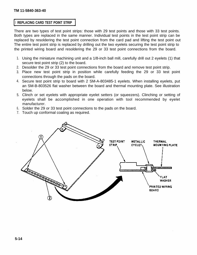
TM 11-5840-363-40
REPLACING CARD TEST POINT STRIP
There are two types of test point strips: those with 29 test points and those with 33 test points.Both types are replaced in the same manner. Individual test points in the test point strip can bereplaced by resoldering the test point connection from the card pad and lifting the test point outThe entire test point strip is replaced by drilling out the two eyelets securing the test point strip tothe printed wiring board and resoldering the 29 or 33 test point connections from the board.
1.
2.3.
4.
5.
6..7.
Using the miniature machining unit and a 1/8-inch ball mill, carefully drill out 2 eyelets (1) thatsecure test point strip (2) to the board.Desolder the 29 or 33 test point connections from the board and remove test point strip.Place new test point strip in position while carefully feeding the 29 or 33 test pointconnections through the pads on the board.Secure test point strip to board with 2 SM-A-803485-1 eyelets. When installing eyelets, putan SM-B-803526 flat washer between the board and thermal mounting plate. See illustrationbelow.Clinch or set eyelets with appropriate eyelet setters (or squeezers). Clinching or setting ofeyelets shall be accomplished in one operation with tool recommended by eyeletmanufacturer.Solder the 29 or 33 test point connections to the pads on the board.Touch up conformal coating as required.
5-14

TM 11-5840-363-40
REPAIRING CONFORMAL COATING (1 of 2)
After all repairs have been completed and the circuit card has been tested for serviceability, theconformal coating must be repaired. This is done by first thoroughly cleaning the areas to berepaired, then brushing on two new coats of conformal coating. Each coat Of the conformal
coating must be cured either at room temperature or in an oven. Oven curing accelerates the curingprocess.
1. Clean areas to be coated.
The solvents used are flammable. Keep away from heat or open flame.Vapors may be harmful; use with adequate ventilation. Avoid prolongedbreathing of vapors. Avoid eye contact. Do not take internally.
a. Using a solvent composed of 50-percent isopropyl alcohol and 50-percent aliphaticnaphtha, scrub the area to be coated with a soft brush until thoroughly clean.
b. Rinse the area with clean unused isopropyl alcohol.
To prevent serious burns, use asbestos gloves when handling hot items.
c. Dry the circuit card for a minimum of 1 hour at 140 ± 11°F in a vented, forced-draft oven.
Cleaned and oven-dried circuit cards must be coated within 16 hours, orbe redried prior to coating. Protect cleaned cards from dust, fingerprints,and other contaminants at all times prior to and during application ofconformal coating.
2. Apply conformal coating.a, Mask any areas such as connectors, test points, and adjustable components that must not
be conformal coated.
NOTE
The conformal coating is stored at room temperature. Unopenedcontainers of the coating can be stored for use up to 12 months. Openedcontainers should be used within 90 days of the time they are opened.
5-15

TM 11-5840-363-40
REPAIRING CONFORMAL COATING (2 of 2)
b. Mix two-part conformal coating material (appendix B, item 5) according to manufacturer’sinstructions.
c. Brush on conformal coating and then air dry for 30 minutes.d. Brush on second coat of conformal coating and allow to air dry for 30 miinutes.
3. Cure conformal coating at 150 ±10°F for 3 hours minimum, or at 225 ±10°F for 1 hourminimum.
5-16
TM 11-5840-363-40
REPAIRING CARDS CONTAINING MOS MICROELECTRONIC CIRCUITS
Because metal oxide semiconductor (MOS) microelectronic circuits are susceptible to damage dueto static electricity, the following procedures must be followed to avoid damage to the deviceduring handling, testing, or actual operation.
When repairing cards with MOS devices, a battery powered soldering ironmust be used.
● Use a grounded work station with an antistatic surface and a conductive wristband.● Keep leads of MOS microelectronic circuits in contact with a conductive material,
except when being tested or in actual operation, to avoid buildup of static charge.● Ground soldering iron tips, metal part of fixtures and tools, and handling facilities.● Do not insert or remove cards from assemblies with power on.● Do not apply signals to card inputs while power supply is off.
5-17/(5-18 blank)

TM 11-5840-363-40
CHAPTER 6
ID AND TEST POINT ADAPTER REPAIR
Page PageIntroduction . . . . . . . . . . . . . . . . . . . . . . . . . . . . . . . . . . 6-1 Repair of Micro circuits. . . . . . . . . . . . . . . . . . . . . . 6-6Repair of Contacts . . . . . . . . . . . . . . . . . . . . . . . . . . 6-2 Repair of Test Point Adapter Contact . . . . . . . 6-8Repair of Connector Receptacle . . . . . . . . . . . . . 6-4 Repair of Test Point Adapter Contacts. . . . . 6-9
This chapter outlines the procedures necessary to repair IDs and test point adapter. All thefacilities and tools required for ID and test point adapter repair are contained in ElectronicEquipment Repair Facility OA-8991/USM-410 (V), except for the connector removal tool (NSN5120-01-084-0440).
Change 1 6-1
INTRODUCTION

TM 11-5840-363-40
REPAIR OF CONTACTS (1 of 2)
This procedure will show you how to replace any of the contacts in the interconnection device (ID).
1.
2.3.4.5,6.7.8.9,
10,
11.12,13,14.15.16.17.18.
Remove six machine screws and washers (7, 8) from adapter back plate (2) on ID enclosure(1).Remove back plate (2) from ID enclosure (1).Remove 6 machine screws and washers (14, 16) from component board (21).Remove component board (21 ) from inside ID enclosure.Remove 6 machine screws and washers (7, 8) from mounting plate (3) on face of ID.Remove mounting plate (3) from ID enclosure (1).Locate damaged contact.Tag and remove each wire with location from which it was removed.Carefully pry connector receptacle (4) from pin plate (3).Unseat contact (42), and using removal/inserter tool (43), pull contact out from the front ofpin plate (40).
Be sure to place contact end so that contacts are alined with groove on pinplate. Damage to contacts may result if not alined properly.
Insert contact (42) into hole of pin plate (3) from the front.Carefully place removal/inserter tool (43) on contact end (42). Then push in until it seats.Reconnect wires to contacts from which they were removed.Install mounting plate in ID enclosure through rear openingSecure mounting plate with 6 machine screws and washers on face of ID.Install component board (21 ) in ID enclosure with microcircuit facing outward.Secure component board in ID enclosure using 6 machine screws and washers(14, 16).Position adapter back plate on ID enclosure (2) and secure with 6 machine screws andwashers (7, 8).
6-2

TM 11-5840-363-40
REPAIR OF CONTACTS (2 of 2)
t
6-3

TM 11-5840-363-40
REPAIR OF CONNECTOR RECEPTACLE (1 of 2)
This procedure will show you how to replace any of the connector housings on the mounting platein the ID.
1.2.3.4.5.6.
7’
8.
9.10.11.12.13.
Remove 6 machine screws and washers (7, 8) from adapter back plate (2) on ID enclosure (1).Remove back plate (2) from ID enclosure (1).Remove 6 machine screws and washers (14, 16) from component board (3).Remove component board (21) from inside ID enclosure.Remove 6 machine screws and washers (7,8) from mounting plate (3) on face of ID.Remove mounting plate from ID enclosure.
Use extreme care not to damage pin plate or pins.
Unseat damaged connector housing (4) by carefully prying housing from mounting plate,using connector removal tool (NSN 5120-01-084-0440) (44).
Both ends of the connector housing must be carefully alined with contact.Damage to contact may result if not alined properly.
Carefully place connector housing (4) on pin plate (3). Tap lightly with connector removal toolto seat connector housing.Install mounting plate in ID enclosure through rear opening.Secure mounting plate with 6 machine screws and washers (14, 16) on face of ID.Install component board (21) in ID enclosure with microcircuits facing outward.Secure component board in ID enclosure using 6 machine screws and washers (7, 8).Position adapter back plate on ID enclosure (1) and secure with 6 machine screws andwashers.
6-4 Change 1

TM 11-5840-363-40
REPAIR OF CONNECTOR RECEPTACLE (2 of 2)
6-5
TM 11-5840-363-40
REPAIR OF MICROCIRCUITS (1 of 2)
This procedure will show you how to replace microcircuits on the component board.
1. Remove 6 machine screws and washers (1) from adapter back plate (2) on ID enclosure,2. Remove back plate (2) from enclosure.3. Carefully pry failed microcircuit (4) from socket on component board (3).
Be sure to place microcircuit in alinement with socket contacts oncomponent board. Damage to microcircuit may result if not alined properly.
4. Place microcircuit in proper position in socket on component board.5. Apply a light, even pressure to microcircuit until microcircuit is seated properly.6. Position adapter back plate on ID enclosure (5) and secure with 6 machine screws and
washers.
6-6

TM 11-5840-363-40
REPAIR OF MICROCIRCUITS (2 of 2)
6-7

TM 11-5840-363-40
REPAIR OF TEST POINT ADAPTER CONTACT
This procedure will show you how to replace the spring-loaded contact (1) on the test pointadapter (2).
1. Using needlenose pliers, pull defective spring-loaded contact (1) from the front side of thetest point adapter (2).
2. Using needlenose pliers, push spring-loaded probe contact into probe contact socket.
6-8

TM 11-5840-363-40
REPAIR OF TEST POINT ADAPTER CONTACTS
This procedure will show you how to replace contacts on the test point adapter.
1. Unsolder defective probe contact socket (1) from etch side of test point adapter (2).2. Using needlenose pliers, pull probe contact socket from front side of test point adapter (2).3. Using needlenose pliers, replace probe contact socket on front side of test point adapter (2).4. Solder probe contact socket in place on etch side of test point adapter (2).5. Using needlenose pliers, push spring-loaded probe contact into probe contact socket.
6-9/(6-10 blank)

A P P E N D I X A
REFERENCES
AR 746-1
CTA 50-970
DA PAM 310-1
MIL-P-45743
MIL-P-46843
SB 11-573
SB 708-41/42
TM 11-6625-2773-12-1
TM 38-750
TM 740-90-1
TM 750-244-2
Marking, Packing, and Shipment of Supplies and EquipmentPackaging of Army Materiel for Shipment and Storage.
Expendable/Durable Items (Except Medical, Common Table ofAllowances, Class V, Repair Parts and Heraldic Items).
Consolidated Index of Army Technical Publications and BlankForms.
Military Specification: Soldering, Manual Type, High Reliability,Electrical and Electronic Equipment.
Military Specification: Printed Wiring Assemblies.
Painting and Preservation Supplies Available for Field Use forElectronics Command Equipment.
Federal Supply Code for Manufacturers; United States and Canada,Name to Code, Code to Name.
Operator’s and Organizational Maintenance Manual (with PartsList) Test Station, Electronic Equipment AN/USM-410 (XE-3A)(V),AN/USM-410 (XE-3B)(V), and AN/USM-410 (XE-3C)(V) (to bepublished).
The Army Maintenance Management System (TAMMS).
Administrative Storage of Equipment.
Procedures for Destruction of Electronics Materiel to PreventEnemy Use.
Change 1 A-1/(A-2 bIank)
TM 11-5840-363-40

TM 11-5840-363-40
A P P E N D I X B
EXPENDABLE SUPPLIES AND MATERIALS LIST
Section I.
INTRODUCTION
This appendix lists expendable supplies and materials you will need to operate and to maintainElectronic Equipment Test Station AN/USM-410(V). These items are authorized to you by CTA50-970, Expendable/Durable Items (Except Medical, Class V, Repair Parts, and Heraldic Items).
EXPLANATION OF COLUMNS
a. Column 1 – Item number. This number is assigned to the entry in the listing and is referenced inthe narrative instructions to identify the material (eg, “Use cleaning compound, item 5, App. B“).
b. Column 2 – National Stock Number. This is the National stock number assigned to the item; use itto request or requisition the item.
c. Column 3 – Description. Indicates the Federal item name and, if required, a description toidentify the item. The last line for each item indicates the Federal Supply Code for Manufacturer(FSCM) in parentheses followed by the part number.
d. Column 4 – Unit of Measure (U/M). Indicates the measure used in performing the actualmaintenance function. This measure is expressed by a two-character alphabetical abbreviation(eg - ea, in, pr). If the unit of measure differs from the unit of issue, requisition the lowest unit ofissue that will satisfy your requirements.
Change 1 B-1
SCOPE

TM 11-5840-363-40
EXPENDABLE SUPPLIES AND MATERIALS LIST
(1) (2) (3) (4)Item National Stock
Number Number Description U/M
1 8030-00-753-5006 Polysulfide compound, MIL-S-8802 CLASS 2 2-1 oz kit8030-00-753-5005 6 oz kit8030-00-753-4599 1/2 pt kit
2 7510-00-159-4986 Adhesive film, NAFCO No. 101 (06530) 50 ft roll
3 6810-00-753-4993 Isopropyl alcohol oz
4 6810-00-223-9069 Aliphatic naphtha, TT-N-97 gal6810-00-664-5278
5 5970-00-181-0190 Conformal coating, MIL-1-46058 Type Pur kit
B-2

TM 11-5840-363-40
Term orAbbreviation
A/D
BITE
BNC
CAL
CRT
DC
DIAG
DIP
DIR
ETE
HSVSU
IC
ID
LED
LSVSU
MEAS
MOS
PCOF
PIU
R
REV
GLOSSARY (1 of 2)
Definition or Description
Analog-to-digital
Built-in test equipment
A type of connector
Calibration
Cathode ray tube
Direct current
Diagnostic
Dual in-line package
Director
End-to-end test
High speed voltage sampling unit
Intermediate code
Interconnection device
Light emitting diode
Low speed voltage sampling unit
Measure
Metal oxide semiconductor
Probable cause of failure
Programmable interface unit
Indicates AN/USM-410 computer subsystem is ready. A UUT maynow be tested.
Revision
G-1

TM 11-5840-363-40
Term orAbbreviation
SAO
SA1
TACFIRE
UUT
1635XXXT00
803XXXT0 orC5000XXXT0
Stuck-at-zero
Stuck-at-one
Tactical fire direction system
Unit under test
Test procedure for 1635XXX and 1642XXX type cards. The second0 after the T indicates test version 0. The first 0 after the T indicatesthe card is 1635XXX-100. If the first number after the T were 1, itwould indicate the card is 1635XXX-101.
Test procedure for SM-D-803XXX and C5000XXX type cards. The 0after the T indicates test version 0.
G-2
Definition or Description
GLOSSARY (2 of 2)

TM 11-5840-363-40
Page Page
A
AN/USM-410(V) testerDescription . . . . . . . . . . . . . . . . . . . . . . . . . . . . . . .Maintenance instructions. . . . . . . . . . . . . . . . . . . . .Operating instructions . . . . . . . . . . . . . . . . . . . . . .
B
Bonded parts, replacing. . . . . . . . . . . . . . . . . . . . . . . . .
C
Card connector repairing . . . . . . . . . . . . . . . . . . . . . . .Card repair overview . . . . . . . . . . . . . . . . . . . . . . . . . . .Card repair parts index . . . . . . . . . . . . . . . . . . . . . . . . .Card test and troubleshooting index . .. . . . . . . . . . . .Card test point strip,replacing . . . . . . . . . . . . . . . . . . .Cleaning cards.. . . . . . . . . . . . . . . . . . . . . . . . . . . . . . .Conformal coating
Removing . . . . . . . . . . . . . . . . . . . . . . . . . . . . . . . . . .Repairing . . . . . . . . . . . . . . . . . . . . . . . . . . . . . . . . . .
Connector receptacle, repair of . . . . . . . . . . . . . . . . . .Contacts
Repair . . . . . . . . . . . . . . . . . . . . . . . . . . . . . . . . . . . . .Repair of test point adapter. . . . . . . . . . . . . . . . . . .
E
Explanation of messages . . . . . . . . . . . . . . . . . . . . . . .
I
ID failure message . . . . . . . . . . . . . . . . . . . . . . . . . . . . .ID hookup . . . . . . . . . . . . . . . . . . . . . . . . . . . . . . . . . . . .ID 1 C5000610
Parts list and parts location . . . . . . . . . . . . . . . . . . .Schematic . . . . . . . . . . . . . . . . . . . . . . . . . . . . . . . .Wire list . . . . . . . . . . . . . . . . . . . . . . . . . . . . . . . . . . .
ID 2 C5000621Parts list and parts location . . . . . . . . . . . . . . . . . . .Schematic . . . . . . . . . . . . . . . . . . . . . . . . . . . . . . . . .Wire list . . . . . . . . . . . . . . . . . . . . . . . . . . . . . . . . . . .
IndexCard repair parts. . . . . . . . . . . . . . . . . . . . . . . . . . . .Card test and trouble shooting. . . . . . . . . . . . . . . . .
2-12-22-1
5-6
5-145-24-44-2
5-145-3
5-55-156-4
6-26-8
4-26
3-34-18
3-43-33-6
3-163-153-18
4-44-2
I (Cont)
Index (cont)Test equipment and accessories. . . . . . . . . . . . . . .Test program. . . . . . . . . . . . . . . . . . . . . . . . . . . . . . .
Inspecting cards. . . . . . . . . . . . . . . . . . . . . . . . . . . . . . .
M
Maintenance forms and records. . . . . . . . . . . . . . . .Microcircuits, repair of. . . . . . . . . . . . . . . . . . . . . . . . .
P
Parts list and parts location1D C5000610. . . . . . . . . . . . . . . . . . . . .ID 2 C5000621 . . . . . . . . . . . . . . . . . . . . . . . . . . . .Test point Adapter cable C5000649 . . . . . . . . . . .Test point adapter cable C5000651 . . . . . . . . . . .Test point adapter cable C5000658 . . . . . . . . . . .Test point adapter 1 C5000628 . . . . . . . . . . . . . .Test point adapter 2 C5000629 . . . . . . . . . . . . . .
R
Removing conformal coating . . . . . . . . . . . . . . . . . . . .Repair of
Connector receptecle. . . . . . . . . . . . . . . . . . . . . . . .Contacts . . . . . . . . . . . . . . . . . . . . . . . . . . . . . . . . . .Microcircuits . . . . . . . . . . . . . . . . . . . . . . . . . . . . . . .Test point adapter contact . . . . . . . . . . . . . . . . . . .Test point adapter contacts. . . . . . . . . . . . . . . . . . .
RepairingCards containing MOS microelectronic circuits . .Conformal coating . . . . . . . . . . . . . . . . . . . . . . . . . .
ReplacingBonded parts.... . . . . . . . . . . . . . . . . . . . . . . . . . . .Card connector. . . . . . . . . . . . . . . . . . . . . . . . . . . . .Card test point strip . . . . . . . . . . . . . . . . . . . . . . . . .
Reporting Equipment lmprovementRecommendations (EIRs) . . . . . . . . . . . . . . . . . . . . . .
4-84-12
5-4
1-16-6
3-43-163-363-383-423-283-32
5-5
6-46-26-66-86-9
5-175-15
5-65-105-14
1-1
Change 1 lndex-1
INDEX (1 of 3)

INDEX (2 of 3)
Page Page
T (cont)
SchematicID 1 C5000610 . . . . . . . . . . . . .ID 2 C5000621 . . . . . . . . . . . . . . . . . . . . . .Test point adapter cable C5000649 . . . . . .Test point adapter cable C5000651 . . .Test point adapter cable C5000658 ... . . . .Test point adapter 1 C5000628 . . . . . . . . . .Test point adapter 2 C5000629 . . . . . . . . . . . .
Scope . . . . . . . . . .
T
Test and troubleshootingCard index. . . . . . . . . . . . . . . . .C5000511 Phase shift computer card . . . . . . . . .SM-D-803125 Data bus encoder card . . . . . . . . .SM-D-803128 Data bus decoder card . . . . . . . . .SM-D-803137 Temperature converter card. . . . .SM-D-803140 Clock oscillator card . . . . . . . . . . .SM-D-803146 Tilt sensor card . . . . . . . . . . ...... .SM-D-803152 Phase shifter driver card. . . . . . . .SM-D-803161 Power supply bite card . . . . . . . .1635841-100 Timing and reset card . .1635842-100 Crowbar sense card. . . . . . . . . .1635843-100 HV and rf sensor card . . . . . . . . . .1635845-100 or -101 HV area sense card .1635846-100 Trigger control card. . . . . . . . . . . .1635847-100 Transmitter go/no go card . . . . . .1635854-100 Beam power supply control card1635870-100 or -101 Phase shift driver card . .1635871-100 Phase shift computer card . . . . .1635872-100 Test driver card . . . . . . . . . . .1635882-100 B-scope video converter card. . . .1635883-100 Computer message control card1635884-100 Clock/tv sync generator card1635885-100 Cursor/video output card1635886-100 B-scope video buffer card. .1635910-100 Doppler filter card . . . .1635911-100 Coefficient generator A card1635912-100 Coefficient generator B card.1635913-100 Process cycle timing card. . . . .1635914-100 Threshold crossing detector
card1635915-100 Target detector card1635916-100 Phase gain bias correction card1635917-100 General purpose flip-flop card
3-33-153-363-393-423-273-31
1-1
4-24-2284-2304-2324-2344-2364-2384-2404-242
4-324-344-364-384-404-424-444-464-484-504-524-544-564-584-604-624-644-664-68
4-704-724-744-76
Test and troubleshooting (cont)1635918-100 Pulsed interference detector card.1635919-100 Target/bite buffer card...............1635920-100 1 K X 24 RAM card. . . . . . . . . . . . .1635921-100 Read control card.....................1635922-100 Command data card.................1635923-100 Collect cycle timing card...........1635924-100 Timing decoder no. 1 card.........1635925-100 Clock oscillator card.................1635926-100 Frame decoder card.................1635927-100 Data bus decodar card................1635928-100 MTI canceller card . . . . . . . . . ......1635929-100 Recombine card. . . . . . . . . . . . . . . . 1635930-100 Signature generator card . . . . . . .1635931-100 Tri-state multiplexer card. . . . . . . .. 1635932-100 Receiver gain control card. . . . . . . .1635933-100 RAM address generator card. . . . . 1635935-100 Differential driver/receiver card. . . 1635936-100 Video input multiplex card. . . . . . 1635937-100 Power supply bite/buffer card. . .1635939-100 General purpose register card. . . .1635940-100 General purpose gate card . . . ..1635941-100 Timing decoder no. 2 card. . . . . .1635942-100 A/D converter card. . . . . . . ........1635944-100 or -101 8-MHz sample and hold
card . . . . . . . . . . . . . . . . . . . . . . . . . . . . . . . . . . . 1635945-100 A/D self-test card. . . . . . . . . . . ...1635946-100 4K RAM card . . . . . . . . . . . . . . .....1635947-100 Mean level select card. . . . .......1635948-100 Accumulator card . . . . . . . .........1635949-100 Composite generator card . . ....1635950-100 I- and Q-track strobe card. . . . . .1635951-100 General verify gate card . . . . .. .1635952-100 Clutter map track correlator card.1635953-100 Clutter map address card1635954-100 Clutter map integrator card.1635955-100 Target count card..............1635956-100 Process cycle signal generator
card. . . . . . . . . . . . . . . . . . . . . . . . . . . . . . . . . . . 1635957-100 Collect cycle signal generator
card. . . . . . . . . . . . . . . . . . . . . . . . . . . . . . . . . . . . . . . .1635960-100 Write control card . . . . . . . . ......1635961-100 Command data control card. . . . . . 1635962-100 Mean Ievel generator card. . . .1635963-100 Integrator and log converter card.. . . .1635964-100 B-scope interface card. . . . . . . .1635967-100 Switch/alpha logic latch card.. . . . .
4-784-804-824-844-864-884-904-924-944-964-98
4-1004-1024-1044-1064-1084-1104-1124-1144-1164-1184-1204-122
4-1244-1264-1284-1304-1324-1344-1364-1384-1404-1424-1444-146
4-148
4-1504-1524-1544-1564-1584-1604-162
Index-2 Change 1
TM 11-5840-363-40
S

TM 11-5840-363-40
Page Page
T (cont)
Test and troubleshooting (cont)1635968-100 Indicator driver card. . . . . . . . . . . .1635969-100 TACFIRE FSK modulator card. . .1635970-100 Easting row/column driver card.1635971-100 Map control card . . . . . . . . . . . . . .1635973-100 Peripheral input/output control
card . . . . . . . . . . . . . . . . . . . . . . . . . . . . . . . .1635975-100 Clutter map track update card . . .1635976-100 Power supply bite card . . . . . . . . .1635977-100 TACFIRE data storage card. . . . . .1635978-100 TACFIRE FSK demodulator card .1635979-100 TACFIRE timing card. . . . . . . . . . .1635985-100 Trailer sync card. . . . . . . . . . . . . . .
4-1644-1664-1684-170
4-1724-1744-1764-1784-1804-1824-184
1635986-100 Data bus encoder card. .. . . . . . . . 4-1861635987-100 Temperature converter card. . . . . 4-1881635988-100 Antenna control card. . . . . . . . . . 4-1901635990-100 Trigger reframe card . . . . . . . . . . . 4-1921642175-100 Memory function interface card. . 4-1941642176-100 Arithmetic register card . . . . . . . . 4-1961642177-100 Microsequencer card. . . . . . . . . .1642178-100 Read only memory 1 card. . . . . . .1642179-100 Read only memory 2 card. . . . . .1642180-100 Read only memory 3 card. . . . . . .1642181 -100 External register control card . . . .1642183-100 External multiplex register card . .1642184-100 External control card . . . . . . . . . . .1642185-100 Program status instruction
decoder card. . . . . . . . . . . . . . . . . . . . . . . . . . . . . .1642186-100 Fast multiplier CORDIC card. . . . .1642187-100 I/O common data path card . . . . .1642188-100 l/O common control card . . .1642189-100 Dual channel control card . . . . . . .1642190-100 Diagnostic panel interface card .1650873-100 External multiplex register card .
4-1984-2004-2024-2044-2064-2104-212
4-2144-2164-2184-2204-2224-2244-226
T (Cont)
Test equipment and accessories. . . . . . . . . . . . . . . .Test equipment and accessories index . . . . . . . . . .Test point adapter 1 C5000628
Parts list and parts location. . . . . . . . . . . . . . . . . . Schematic. . . . . . . . . . . . . . . . . . .
Test point adapter 2 C5000629Parts list and parts location. . . . . . . . . . Schematic . . . . . . . . . . . . . . . . . . . . . . . . . .
Test point adapter cable C5000649Parts list and parts location. . . . . . . . . . . . . . . .Schematic. . . . .. . . . . . . . . . . .
Test point adapter cable C5000651Parts list and parts location. . . . . . . . . . . . . . .Schematic. . . . . . . . . . . . . . . . . . . . . . . . . . . .
Test point adapter cable C5000658Parts list and parts Iocation. . . . . . . . . . . . . . . .Schematic. . . . . . . . . . . . . . . . . . . . . . . . . . . .
Teat program index . . . . . . . . . . . . . . . . . . . . . .
U
UUT hookup. . . . . . . . . . . . . . . . . . . . . . . . . . .UUT and ID removal. . . . . . . . . . . . . . . . . . .UUT probing. . . . . . . . . . . . . . . . . . . . . . . . . . . .
W
Wire IistID 1 C5000610 . . . . . . . . . . . . . . . . . . . . . ... .ID 2 C5000621 . . . . . . . . . . . . . . . . . . . . . . . . .
3-14-8
3-283-27
3-323-31
3-363-36
3-383-39
3-423-424-12
4-204-244-30
3-63-18
US. GOVERNMENT PRINTING OFFICE : 1989 - 242-451 (05370)
Change 1 lndex-3/(lndex-4 blank)
INDEX (3 of 3)

R:\363-40\FO-1.TIF
Printed by ViewDirector Version 2.100 demonstration application

R:\363-40\FO-2.TIF
Printed by ViewDirector Version 2.100 demonstration application

R:\363-40\F0-3.TIF
Printed by ViewDirector Version 2.100 demonstration application

R:\363-40\FO-4.TIF
Printed by ViewDirector Version 2.100 demonstration application

R:\363-40\FO-5.TIF
Printed by ViewDirector Version 2.100 demonstration application

R:\363-40\FO-6.TIF
Printed by ViewDirector Version 2.100 demonstration application

R:\363-40\FO-7.TIF
Printed by ViewDirector Version 2.100 demonstration application

R:\363-40\FO-8.TIF
Printed by ViewDirector Version 2.100 demonstration application

R:\363-40\FO-9.TIF
Printed by ViewDirector Version 2.100 demonstration application

R:\363-40\FO-10.TIF
Printed by ViewDirector Version 2.100 demonstration application

R:\363-40\FO-11.TIF
Printed by ViewDirector Version 2.100 demonstration application

R:\363-40\FO-12.TIF
Printed by ViewDirector Version 2.100 demonstration application

By Order of the Secretary of the Army:
Official:
ROBERT M. JOYCEMajor General, United States Army
The Adjutant General
DISTRIBUTION:
To be distributed in accordance with Special List.
E. C. MEYERGeneral, United States Army
Chief of Staff
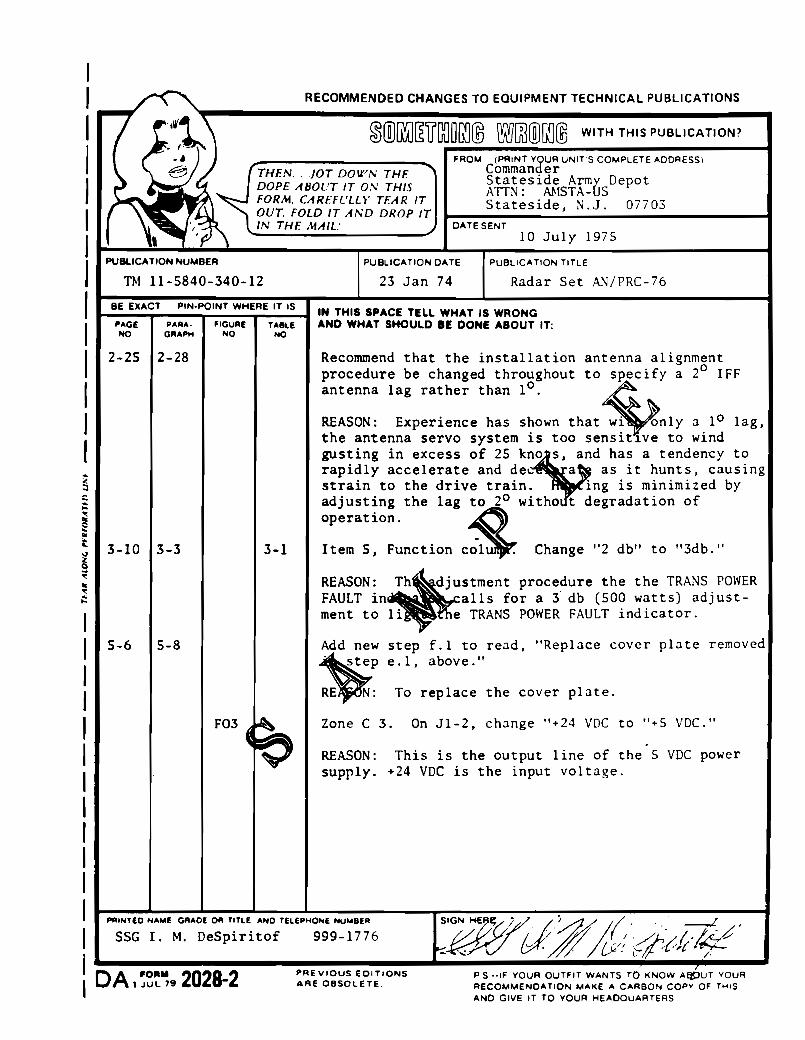


PIN: 051743-001
This fine document...
Was brought to you by me:
Liberated Manuals -- free army and government manuals
Why do I do it? I am tired of sleazy CD-ROM sellers, who take publicly available information, slap “watermarks” and other junk on it, and sell it. Those masters of search engine manipulation make sure that their sites that sell free information, come up first in search engines. They did not create it... They did not even scan it... Why should they get your money? Why are not letting you give those free manuals to your friends?
I am setting this document FREE. This document was made by the US Government and is NOT protected by Copyright. Feel free to share, republish, sell and so on.
I am not asking you for donations, fees or handouts. If you can, please provide a link to liberatedmanuals.com, so that free manuals come up first in search engines:
<A HREF=http://www.liberatedmanuals.com/>Free Military and Government Manuals</A>
– SincerelyIgor Chudovhttp://igor.chudov.com/
– Chicago Machinery Movers