radial 16 canal and road between 5 ring and 30 de … 16 canal and road between 5th ......
TRANSCRIPT

Radial 16 Canal and Road Between 5th Ring and 30th de Agosto Curichi
Submitted By: Tip Third Engineering
Abdoulie Barry
Scott Bauer Morgan Davis
Branden Strayer
Submitted To: District 10 Santa Cruz, Bolivia
November 3, 2008
Michigan Technological University Civil and Environmental Engineering
1400 Townsend Drive Houghton, MI 49931

30th de Agosto Curichi Design Report i
Disclaimer This design report was completed by International Senior Design students at Michigan Technological University for a class project. This report must be checked and approved
by a licensed Professional Engineer for accuracy before implementation.

30th de Agosto Curichi Design Report ii
Acknowledgments
Ing. Linda Phillips Ing. Dennis Magolan Ing. Mike Drewyor Ing. Waldo Varas Ing. Juan Carlos Martinez Ing. Javier Marín Sr. Horacio Cardenas Heather Wright Marilyn Phillips Lic. Carmen Arias Palacios Giancarlo Calbimonte – ISD August Mentor Amanda Schmidt – ISD August Mentor Karina Jousma – ISD August Mentor Dr. Brian Barkdoll Sub-Alcaldesa. Jannet Carmona Ing. Kendy Montenegro Ing. Edil Aponte Sr. Moisés Herbas Rico Faculty and Staff of the Colegio Walter Henry School Dr. Dan Hinojosa and family Aerial Engineering Cinco Cero Engineering Don Jaguar Engineering Señor Design Engineering
30th de Agosto Curichi Design Report iii
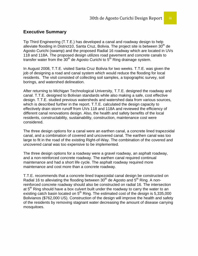
Executive Summary Tip Third Engineering (T.T.E.) has developed a canal and roadway design to help alleviate flooding in District10, Santa Cruz, Bolivia. The project site is between 30th de Agosto Curichi (swamp) and the proposed Radial 16 roadway which are located in UVs 118 and 118A. The proposed design utilizes road pavement and concrete canals to transfer water from the 30th de Agosto Curichi to 5th Ring drainage system. In August 2008, T.T.E. visited Santa Cruz Bolivia for two weeks. T.T.E. was given the job of designing a road and canal system which would reduce the flooding for local residents. The visit consisted of collecting soil samples, a topographic survey, soil borings, and watershed delineation. After returning to Michigan Technological University, T.T.E. designed the roadway and canal. T.T.E. designed to Bolivian standards while also making a safe, cost effective design. T.T.E. studied previous watersheds and watershed data from various sources, which is described further in the report. T.T.E. calculated the design capacity to effectively drain storm runoff from UVs 118 and 118A and reviewed the efficiency of different canal renovations design. Also, the health and safety benefits of the local residents, constructability, sustainability, construction, maintenance cost were considered. The three design options for a canal were an earthen canal, a concrete lined trapezoidal canal, and a combination of covered and uncovered canal. The earthen canal was too large to fit in the road of the existing Right-of-Way. The combination of the covered and uncovered canal was too expensive to be implemented. The three design options for a roadway were a gravel roadway, an asphalt roadway, and a non-reinforced concrete roadway. The earthen canal required continual maintenance and had a short life cycle. The asphalt roadway required more maintenance and cost more than a concrete roadway. T.T.E. recommends that a concrete lined trapezoidal canal design be constructed on Radial 16 to alleviating the flooding between 30th de Agosto and 5th Ring. A non-reinforced concrete roadway should also be constructed on radial 16. The intersection at 5th Ring should have a box culvert built under the roadway to carry the water to an existing catch basin located on 5th Ring. The estimated cost of the design is 5,335,000 Bolivianos ($762,000 US). Construction of the design will improve the health and safety of the residents by removing stagnant water decreasing the amount of disease carrying mosquitoes.

30th de Agosto Curichi Design Report iv

30th de Agosto Curichi Design Report v
Table of Contents Acknowledgements .................................................................................................................... ii
Executive Summary ................................................................................................................... iii
1.0 Introduction ........................................................................................................................... 1
2.0 Background ........................................................................................................................... 1
2.1 Bolivia .................................................................................................................................. 1
2.2 Santa Cruz .......................................................................................................................... 2
2.3 Districts ................................................................................................................................ 3
2.4 UVs ...................................................................................................................................... 4
2.5 Flooding ............................................................................................................................... 4
2.6 Curichi ................................................................................................................................. 4
2.7 Proposal .............................................................................................................................. 5
2.8 Health .................................................................................................................................. 6
2.9 Politics and Funding ............................................................................................................ 6
3.0 Methods and Procedures ..................................................................................................... 7
3.1 Bolivia .......................................................................................................................... 7
3.1.1 1st Topographic Survey – 6th Ring ................................................................ 7
3.1.2 2nd Topographic Survey – Radial 16 ............................................................. 8
3.1.3 Soil Borings .................................................................................................. 8
3.1.4 Soil Classification ....................................................................................... 10
3.2 United States ............................................................................................................. 10
3.2.1 Storm Runoff Calculations .......................................................................... 10
3.2.2 Drainage Design ......................................................................................... 12
3.2.3 Computer Aided Drafting (CAD) ................................................................. 13
4.0 Existing Conditions ............................................................................................................ 15
4.1 Site Tour .................................................................................................................... 15
4.2 Curichi ....................................................................................................................... 16
4.3 Project Site ................................................................................................................ 17
4.4 Earthen Canal ........................................................................................................... 20
4.5 5th Ring Intersection .................................................................................................. 20
4.6 Storm Water Flow ..................................................................................................... 21

30th de Agosto Curichi Design Report vi
4.7 Closing Statement ..................................................................................................... 22
5.0 Design Options ................................................................................................................... 22
5.1 Locations of Canal .................................................................................................... 22
5.2 Canal Design Options ............................................................................................... 24
5.2.1 Earthen Canal Option ................................................................................. 24
5.2.2 Concrete Lined Trapezoidal Canal Option ................................................. 26
5.2.3 Combinations of Covered and Uncovered Concrete Lined Trapezoidal Canal .......................................................................................................... 28
5.3 Radial 16 Roadway Design Options ......................................................................... 29
5.3.1 Gravel Roadway ......................................................................................... 30
5.3.2 Non-Reinforced Concrete Roadway ........................................................... 31
5.3.3 Asphalt Concrete Roadway ........................................................................ 31
5.3.4 Roadway Recommendation ....................................................................... 32
6.0 Final Recommendation ...................................................................................................... 32
6.1 Considerations .......................................................................................................... 32
6.2 Canal Recommendations .......................................................................................... 33
6.3 Roadway Recommendations ................................................................................... 34
7.0 Cost – Benefit Analysis ...................................................................................................... 34
7.1 Canal Cost Estimates ................................................................................................ 34
7.2 Roadway Cost Estimates .......................................................................................... 35
7.3 Benefits and Implications .......................................................................................... 37
8.0 Conclusion .......................................................................................................................... 38
9.0 References ........................................................................................................................... 38
Appendix A – Meeting Minutes ................................................................................................ 39
Appendix B – Soil Field Data and Classification ................................................................... 45
Appendix C – Canal Design ..................................................................................................... 55
Appendix D – Pavement Design .............................................................................................. 71
Appendix E – Cost Estimate .................................................................................................... 75
Construction Documents ......................................................................................................... 95
30th de Agosto Curichi Design Report vii
List of Figures
Figure 2.1: Maps Showing Location of Project in Santa Cruz (A), Bolivia (B) .............................. 2
Figure 2.2: Map Showing District 10 in the City of Santa Cruz ..................................................... 3
Figure 2.3: Picture Showing the Refuse Being put into the Northeastern Edge of Curichi ........... 5
Figure 3.1: An Aerial View of the Two Soil Boring Sites ............................................................... 9
Figure 4.1: Map Showing District 10 and 30th de Agosto Curichi Site ......................................... 16
Figure 4.2: An Aerial View of the Curichi Site Showing the Flooded Area in Blue ...................... 17
Figure 4.3: The Current Road System on Radial 16 ................................................................... 18
Figure 4.4 Pictures of the Earthen Canal; Left – Facing Curichi, Right – Facing 5th Ring .......... 19
Figure 4.5: 5th Ring and Radial Intersection Looking Southwest Towards Curichi ..................... 19
Figure 4.6: Broken Grate on the Northeast Side of 5th Ring Intersection .................................... 20
Figure 4.7: 5th Ring Intersection (A – Looking into the Southwest; B – Looking Northeast ......... 21
Figure 4.8: A Photograph of Rio Piraí During the Dry Season .................................................... 22
Figure 5.1: Map Showing Two Location Alternatives for Canal .................................................. 23
Figure 5.2: A Common Earthen Canal in Bolivia ........................................................................ 25
Figure 5.3: Design of Earthen Canal ........................................................................................... 25
Figure 5.4: A Common Concrete Canal in Bolivia ...................................................................... 27
Figure 5.5: Trapezoidal Concrete Lined Canal Design ............................................................... 27
Figure 5.6: An Aerial View Showing the Proposed Covered Section .......................................... 29
Figure 5.7: A Poorly Graded Gravel Road .................................................................................. 30
Figure 5.8 Dimensions of Roadway Options (A – Gravel, B – Asphalt, C – Non-Reinforced Concrete) ................................................................................................................... 32
Figure 7.1: Final Design Recommendation for Project Site ........................................................ 37
List of Tables Table 3.1: Coefficients of Superficial Drainage as Assumed from Marin’s Report...................... 11
Table 3.2: Sample AutoCAD Points from T.T.E. ........................................................................ 15
Table 7.1: Cost Estimate for Open Concrete Canal .................................................................... 34
Table 7.2: Cost Estimate for Partially Covered Canal ................................................................. 35

30th de Agosto Curichi Design Report viii
Table 7.3: Cost Estimate for Gravel Roadway ............................................................................ 35
Table 7.4: Cost Estimate for Asphalt Roadway .......................................................................... 36
Table 7.5: Cost Estimate for Non-Reinforced Concrete Roadway .............................................. 36
Table 7.6: Cost Estimation for Final Recommendation ............................................................... 36

30th de Agosto Curichi Design Report 1
1.0 Introduction
In the summer of 2008, a group of students from Michigan Technological
University traveled to Santa Cruz, Bolivia to gather data and propose engineering
solutions for a canal and roadway near a wetland (curichi). This team of 4 students,
called Tip Third Engineering (T.T.E.), is part of the 2008 International Senior Design
class working on Senior Design projects in Santa Cruz. The students work on local
infrastructure projects such as designing storm water transport systems, roadways, and
solutions to wastewater problems at local schools and government buildings.
Tip Third Engineering is part of the August 2008 group. The city officials of
District 10 of Santa Cruz, Bolivia gave T.T.E. a project to design a canal and roadway in
District 10 in the southwest side of the city of Santa Cruz to remove storm water that
floods in a wetland (curichi) during the rainy season. The flooded area creates standing
water which becomes a breeding ground for disease carrying mosquitoes and creates
transportation problems for the local residents. T.T.E. was asked by city officials to
design a canal to remove the flood water and transport to a drainage system. T.T.E.
surveyed the area, took soil borings, performed soil tests, and returned to Michigan
Tech to develop an engineering report with a final recommendation and construction
documents.
2.0 Background
2.1 Bolivia Bolivia, the 28th largest country in the world, is a landlocked country in central
South America. It has a total area (land and water) of 1,098,580 sq. kilometers (424,135
sq. miles). Bolivia shares borders with Brazil on the north and east, Chile and Peru on

30th de Agosto Curichi Design Report 2
the west, and Argentina and Paraguay on the south. The climate varies with altitude
from humid and tropical to cold and semiarid. The western part of the country is mainly
highlands as opposed to the lowlands of the east. The highest point above sea level is
at 6542m (21463 ft) and the lowest point is at 90m (295ft). Bolivia is divided in nine
departments (provinces); Beni, Chuquisaca, Cochabamba, La Paz, Oruro, Pando,
Potosi, Tarija, and Santa Cruz.
http://www.destination360.com/south-america/bolivia/bolivia-map.php http://www.bolivia-explorer.com/images/bolivia-map.gif
A B Figure 2.1: Maps Showing Location of Project in Santa Cruz (A), Bolivia (B).
2.2 Santa Cruz
The design project is located in Santa Cruz, the largest department in Bolivia,
which is in the eastern part of Bolivia and with a total area of 370,621 sq. kilometers
(143098 sq. miles). Santa Cruz de la Sierra (Santa Cruz henceforth) is the capital city of
the department of Santa Cruz. It has a population of approximately 2.4 million (2005
estimates). Santa Cruz is located at an elevation approximately 416m (1365 ft) above
sea level and 17˚ South Latitude. The weather is semitropical with an annual average

30th de Agosto Curichi Design Report 3
temperature of 21 degrees Celsius. January and February are the months where the
highest amount of rainfall occurs.
Map given by District 10 Representatives
Figure 2.2: Map Showing District 10 in the City of Santa Cruz
2.3 Districts
Santa Cruz’s street layout comprises a concentric ring model with the downtown
located at the center. This project is located on the 5th ring of the city. The city of Santa
Cruz is divided into districts, each with its own sub-mayor. This drainage and roadway
design project is located in District 10, in the southwest region of the city. District 10 is
unique because it is one of a few decentralized districts, meaning District 10 has its own
professional staff, such as engineers, who work only on District 10 projects.
30th de Agosto Curichi Design Report 4
2.4 UVs Within the districts, the neighborhoods are referred to as urbanization vecinals or
“UVs”. The design project is within UVs 118 and 118A. The UVs are further broken
down into groups of neighborhood blocks or “barrios.” The flooding problem in District
10 affects Barrio 30° de Agosto (30th of August).
2.5 Flooding Bolivia has two seasons: rainy and dry. In certain areas of Santa Cruz, flooding
occurs during the November through March rainy season due to the substantial rainfall
and also because the terrain is flat. The local people described flooding in this area as
“high as their knees” and the residents’ health and travel are affected by this flooding.
2.6 Curichi A curichi is a wetland or swamp area. The 30 de Agosto curichi was initially a
smaller natural wetland. It was later enlarged by the removal of native clay soil for brick
making. The large amount of clay removal resulted in a significant body of water about a
square kilometer in size. The 30th de Agosto curichi has served as a retention basin for
the local watershed, but its capacity is decreasing due to the city and residents using it
as a landfill or disposal area for garbage. This practice aggravates the flooding problem
and introduces chemicals and biological agents into the flood waters. A drainage canal
will to help reduce the flooding of homes near the curichi, however water contamination
remains a concern.

30th de Agosto Curichi Design Report 5
Photograph taken by T.T.E.
Figure 2.3: Picture Showing the Refuse Being put into the Northeastern Edge of Curichi
2.7 Proposal
The curichi is being filled with the local’s garbage and this reduces curichi
capacity and increases the flooding problem. Some District 10 residents have been
working with the local government officials to prevent this persistent problem and
District officials want the east end of the curichi filled so they can construct the 6th Ring
road. T.T.E. will design a drainage canal and roadway between 5th Ring and 6th Ring to
alleviate the flooding while also providing a more feasible roadway.

30th de Agosto Curichi Design Report 6
2.8 Health
The flooding near the curichi can affect the local residents’ health. Standing
water creates a breeding area for mosquitoes which can carry diseases such as
malaria, yellow fever, and dengue. Children swim and play in the standing water and
suffer from skin rashes, infections, and other illnesses. Sanitary sewer piping is
currently being installed in the area, but until residents connect to the new system,
storm or curichi water could cause illness by mixing with wastewater from individual
septic systems. If people consume contaminated water, they could suffer from illnesses
such as diarrhea, cholera, hepatitis, or typhoid fever. A drainage canal and roadway
should alleviate the standing flood water outside the curichi. The new canal, in addition
to the new sanitary sewer system, should reduce some of these health issues.
The issue of the debris and refuse being placed in the curichi was not part of
T.T.E.’s scope due to District 10 representatives’ request. The reason is because a
current PhD candidate and former ISD student at Michigan Technological University,
Heather Wright Wendell, is researching environmental restoration of the curichi.
2.9 Politics and Funding Engineering infrastructure projects are funded through the Bolivian Central
government located in the capital city of La Paz. The money generated from each
department goes to the central government in La Paz, who redistributes it to the
departments and cities. The city council then decides which projects will receive
funding. Funding for this drainage canal and roadway design will be subject to the
decisions of the central government, the city of Santa Cruz, and District 10 priorities.

30th de Agosto Curichi Design Report 7
3.0 Methods and Procedures
The design for the Curichi Drainage project was done following a systematic
series of steps. The design steps followed are as are outlined below:
3.1 Bolivia
1. T.T.E. had a meeting with Linda Phillips, P.E., P.M.P. (Professor of Practice, construction engineering at Michigan Technological University). At this meeting Professor Phillips introduced the new project to T.T.E. and outlined her expectations. T.T.E. had meeting with Heather Wright, an Environmental Engineering PhD Student at Michigan Technological University. Heather worked on the Curichi for her International Senior Design project in 2005. She is working with the City Council of Santa Cruz to improve the condition of the Curichi.
2. T.T.E. had a meeting with the District 10 Drainage and Road Engineer to define the scope of the problem and ask them questions about the Curichi and the District’s expectations of the project. The meeting minutes can be found in Appendix #.
3. T.T.E. went on a site tour of the Curichi with the District 10 Representatives Ing. Waldo Varas and City Official Horacio Cardenas to familiarize the team with the project and the surrounding area.
4. T.T.E. photographed the site. 5. T.T.E. performed a preliminary topographic survey of the curichi. 6. Soil borings were performed to determine the makeup of the soil and
determine the depth of the water table. 7. T.T.E. held a second meeting with the District 10 Engineers to discuss the
Curichi project in further detail. The minutes from this meeting can be found in Appendix #.
8. T.T.E. also walked the project site to determine the watershed.
The detailed steps of the preliminary survey, the final topographic survey, and
the soil borings will be discussed in detail in this section.
3.1.1 1st Topographic Survey – 6th Ring
The tools and equipment utilized for the topographic survey were:
‐ Topcon GTS 225 total Station ‐ Tripod ‐ TDS Ranger data collector ‐ Prism ‐ Candy cane prism pole

30th de Agosto Curichi Design Report 8
‐ Metric tape measure ‐ Large nails ‐ Bright colored tape ‐ Bright colored spray paint ‐ Radio walkie-talkies ‐ Computer
T.T.E. performed a preliminary topographic survey of 6th Ring to determine the
feasibility of option in draining the flood water from the curichi. The procedures used are
as follows:
1. Found a control point which was benchmark 23 2. Set up tripod with Top Con total station on top 3. Connected the TDS data collector 4. Measured both the prism and total station height from ground then input
into data collector 5. Established a starting point to determine elevation by performing a
backshot of the benchmark 6. Took the relative sideshots such as right-of-ways, intersections, catch
basins, etc. 7. Used radio walkie-talkies to communicate if sideshots were recorded 8. Traversed to next position and repeated steps 1 - 7. 9. Input data into computer
3.1.2 2nd Topographic Survey – Radial 16 The 2nd survey was done for Radial 16 and the same equipment, tools, and
procedures used in 3.1.1 were applied.
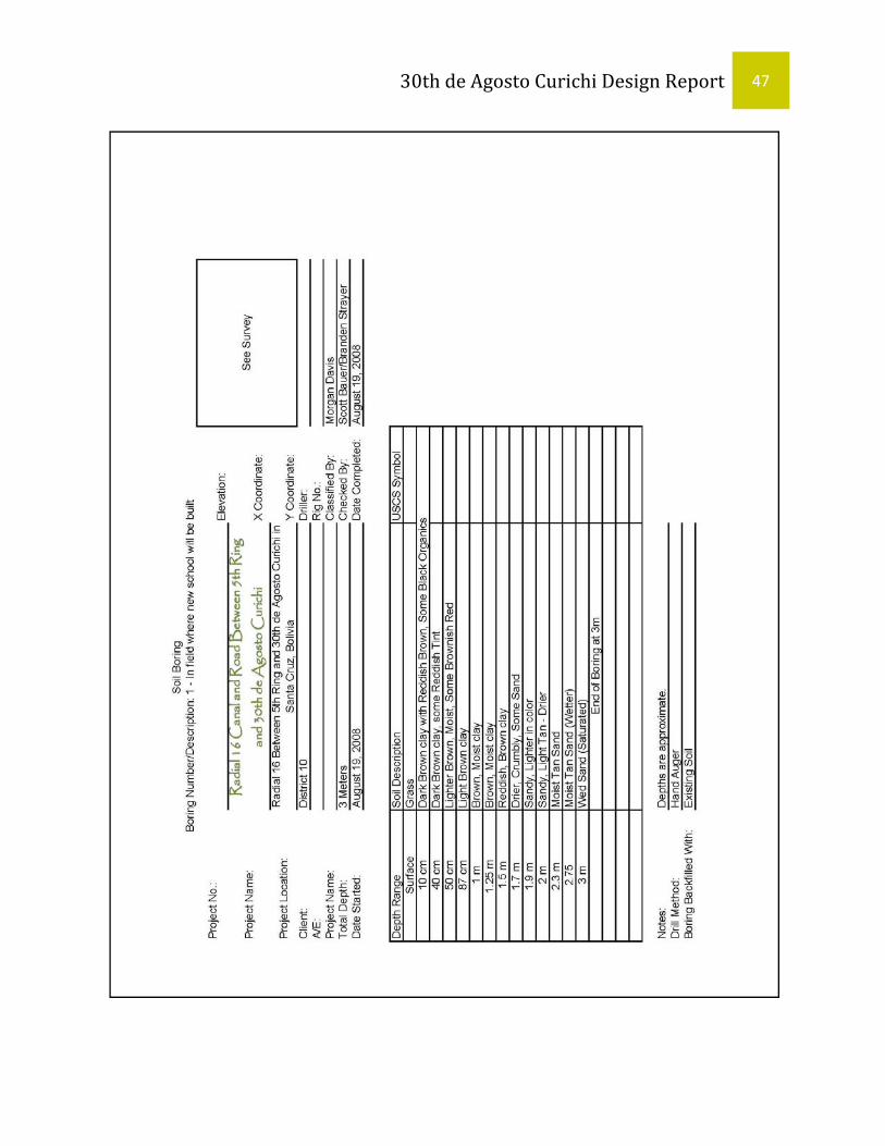
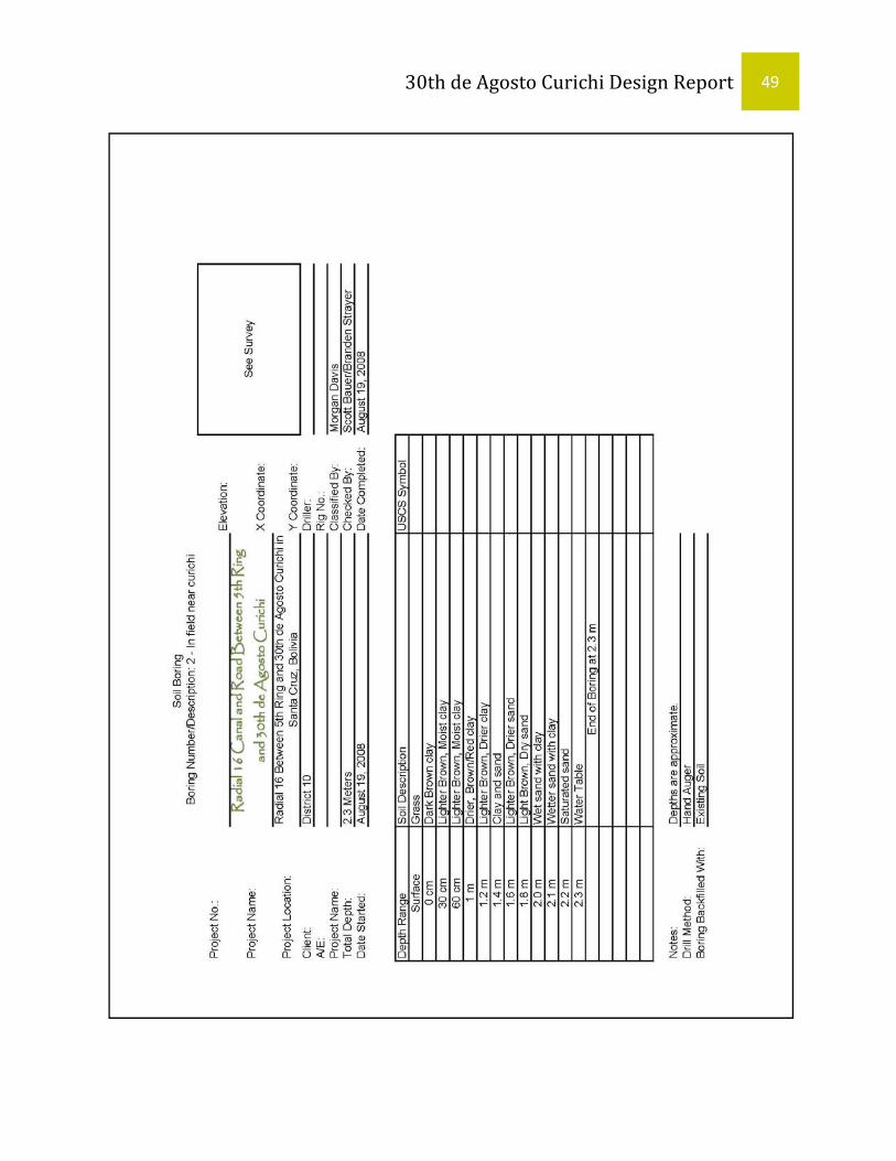
3.1.3 Soil Borings
T.T.E. performed two soil borings to gather information on the soil stratification in
the project area. One boring was taken near the school end (5th Ring) of the proposed
roadway and the other was on opposite end near the curichi (Figure 3.1). The following
procedure outlines how to perform soil borings.

30th de Agosto Curichi Design Report 9
Image taken from Google Earth; edited by T.T.E.
Figure 3.1: An Aerial View of the Two Soil Boring Sites
1. Select and note location for boring 2. Use post digging tool to form hole in undisturbed soil until reservoir of tool
is full. 3. Remove post digging tool from the hole, and empty the soil into a stockpile
near the hole. 4. Note soil characteristics including color and dampness. 5. Repeat steps two through four until depth of hole is equal to one meter. At
one meter down, remove the sample and place as much of the soil as possible into plastic bag labeled with location and depth.
6. Repeat steps two through five at one meter intervals until maximum reach of the tool is met or the water table is found.
7. Reserve the soil in the bags for classification and other soil tests. Return the soil in the stockpile to the hole.
The results of the soil borings can be found in Appendix B.
30th de Agosto Curichi Design Report 10
3.1.4 Soil Classification T.T.E. performed soil classification to find out the makeup of the soil in the
project area to determine whether they were sand and clay. The soil for this test was
obtained during the soil borings on site. The following procedure outlines the soil
classification.
1. Obtain soil sample from soil borings. 2. Follow the worksheet (Appendix B) to determine clay content. 3. Note color, texture, water content, and other physical characteristics. 4. Classify soil. 5. Repeat steps one through four for all the samples.
The results of the soil classifications can be found in Appendix B.
3.2 United States 3.2.1 Storm Runoff Calculations
The quantity of overland storm runoff was calculated for design of the drainage
canal. To calculate the amount of overland storm runoff the rational method was utilized
and can be seen in Equation 1.
3
2
( - 1)
( )
(0 1.0)
Rainfall ( )
( )
Q CIA EquationmQ Peak Storm Runoffs
C Dimensionless Runoff Coefficient CmI Intensitys
A Drainage Area m
=
=
= ≤ ≤
=
=
An empirical rainfall intensity equation for the department of Santa Cruz,
Equation 2, from the Norma Boliviana (NB) 688 and time of concentration equation

30th de Agosto Curichi Design Report 11
obtained from a local engineer, Equation 3, were employed in computing rainfall
intensity.
0.3556
0.7016
0.3852
393.70* ( ) ( - 2)
Rainfall
Rainfall ( ) (min)
0.06625* ( - 3c
fSanta Cruz I EquationtmmI Intensityhr
f Frequency yearst Time of Concentration
Lt EquationS
=
⎛ ⎞= ⎜ ⎟⎝ ⎠
==
⎛ ⎞= ⎜ ⎟
⎝ ⎠)
( ) ( %)
L Hydraulic Length kmS Land Slope decimal
==
Table 3.1: Coefficients of Superficial Drainage as Assumed from Marin’s Report
Runoff coefficients from Table 1 of Chapter 6 in NB 688, Table 3.1, were used to
find a value for C, the dimensionless runoff coefficient.
(a) (b)
0.70 to 0.95
0.50 to 0.70 0.8
0.30 to 0.50
0.40 to 0.60
0.60 to 0.75
0.25 to 0.40
0.5
0.35
0.50 to 0.80
0.60 to 0.90
0.10 to 0.25 0.2
0.70 to 0.95
0.80 to 0.95
(a) coefficients recommended according to different sources
(b) adopted for the stormwater drainage design for the city of Santa Cruz
concrete streets
Single family homes
Separated Multi‐family dwellings
Connected multi‐family dwellings
Suburban
Inside of the 2nd or 3rd rings
zone outside of the 3rd ring s/ pavement
industrial zones
light
heavy
parks, cemeteries and hospitals
paved streets
Coefficients of Superficial DrainageDescription of Area Runoff Coefficient
Commercial Area
Commercial‐ Residential Area

30th de Agosto Curichi Design Report 12
A storm recurrence interval of 10 years and runoff coefficient c in Table 3.1 were
assumed for the 30th de Agosto curichi site. The equipment and errors, assumptions,
and considerations are covered below.
Equipment used:
a) Norma Boliviana (NB) 688 b) “Water Resources Engineering” Ralph A. Wurbs and Wesley P. James
Errors, Assumptions, and Considerations:
a) Runoff coefficient was based on development plans provided by the Sub Alcalde, Ing. Victor P. Escobar Díaz, and District 12 engineer, Ing. Javier Marín.
3.2.2 Drainage Design
Two different types of drainage structures were used in the preliminary design at
the project site: box culverts, and open channels. To size these structures, Manning’s
equation for open channel flow was used, Equation 4; along with the overland storm
runoff for a storm with a 10 year recurrence interval. Procedures, calculations, and
supporting material can be found in the Appendix C.
2 13 2* * * ( - 4)
1 , 1.49 ( ) ' ( )
mfull
m
CQ A R S Equationn
C for SI units and for BG units unitless coefficientn Manning s Roughness Coefficient unitless coefficient
A Cross Sectional Area of Structure
=
==
= ( )2
; ( )
( %)
m
AreaR Wetted Perimeter mPerimeter
S Longitudinal Slope of Channel Decimal
=
=
Canal thickness was based on section drawings from Proyecto Canal Calama
Distr. MPAL 10. These drawings were obtained by previous ISD students and were

30th de Agosto Curichi Design Report 13
supplied to T.T.E. by Ing. Linda Phillips. The equipment and errors, assumptions, and
considerations are covered below.
Equipment used:
a) Proyecto Canal Calama Distr. MPAL 10 b) “Water Resources Engineering” Ralph A. Wurbs and Wesley P. James
Errors, Assumptions, and Considerations:
a) Canal reinforcement was based off of previous projects completed in Santa Cruz. Reinforcement should be checked by a structural engineer for lateral earth and traffic loading pressures.
3.2.3 Computer Aided Drafting (CAD)
AutoCAD Civil 3D 2008 was utilized to display the survey data collected in Santa
Cruz and used to model the proposed roadway and canal. AutoCAD drawings were
also used to delineate the watershed and calculate canal and roadway parameters. The
survey data was imported from the data collector and analyzed. The raw data was
adjusted by adding a constant elevation of 325.649 m to the surveyed elevations. This
transformed the raw data based on a benchmark at 100.732 meters above sea level to
real data with a benchmark at 425.649 meters above sea level. After this adjustment
was made, the points were rotated to the correct orientation.
The equipment and errors, assumptions, and considerations are covered below.
Equipment used:
a) AutoCAD Civil 3D 2008
Errors, Assumptions, and Considerations:
a) Rotation of misaligned points caused marginal error.

30th de Agosto Curichi Design Report 14
b) Existing road boundaries were identified from survey data, Google Earth
images, and District 10 files.
AutoCAD Civil 3D 2008 Procedures:
1. Import survey data 2. Adjust elevations. 3. Rotate to correct alignment 4. Use Civil 3D tools to create a polyline centerline on existing roadway and
canal and create a topographic map of the data 5. Use Civil 3D tools to create a surface from the survey information of the
existing roadway and canal. 6. Use Civil 3D tools to create profile view of existing topographic conditions 7. Use Civil 3D tools to create cross section views of existing topographic
conditions every 25 m 8. Draw proposed roadway profile into existing profile and use to calculated
earthwork quantities (cut and fill) 9. Draw proposed canal cross section into existing cross sections. 10. Create details drawings of roadway and canal elements 11. Plot drawings
The survey points were imported into AutoCAD Civil 3D 2008 as a text file. Table
3.2 shows a portion of the survey data imported for the AutoCAD drawings. The
complete survey information is included on the attached data CD.

30th de Agosto Curichi Design Report 15
Table 3.2: Sample AutoCAD Points from T.T.E.
Point Name X Y Surveyed Elevation
1 start 10000 10000 100 2 bm23 10098.9 10000 100.732 3 rd1 10052.96 9951.28 99.712 4 rd2 10048.38 9944.387 99.684 5 rd3 10045.7 9941.308 99.625 6 rd4 10039.22 9931.091 99.604 7 rd5 10035.44 9924.58 99.594 8 cb1 10038.9 9928.031 99.712 9 cb2 10040.09 9927.24 99.739 10 cb3 10037.43 9923.021 99.745 11 cb4 10034.72 9918.773 99.749 12 cb5 10033.35 9919.669 99.744 13 cb6 10036.77 9923.398 99.55 14 cb7 10036.65 9923.165 98.47 15 rd6 10029.47 9930.825 99.582
4.0 Existing Conditions 4.1 Site Tour T.T.E. first visited the 30th de Agosto curichi with District 10 representatives Ing.
Waldo Varas and Sr. Horacio Cardenas in August 2008. Figure4. 1 shows District 10
outlined in white. The main road between 5th Ring and 6th Ring is Radial 16 which can
be seen in red on Figure 4.1. The location of T.T.E.’s project site is in the northeastern
section of District 10 between 5th and 6th Ring roads. The 5th Ring road is a paved 2
lane road with heavy traffic. Currently the 6th Ring road is not continuous as it is
interrupted by the 30th de Agosto curichi. The city however plans to fill this area of the
curichi to complete the 6th Ring road.
The watershed is delineated by the larger white outline which is approximately
1.0 km2. The area was determined using a combination of data received from Ing.

30th de Agosto Curichi Design Report 16
Cardenas and Ing. Varas, walking the site to find high points while in Santa Cruz, and
using an AutoCAD drawing file with elevations obtained from District 10 officials.
Image taken from Google Map; edited by T.T.E.
Figure 4.1: Map Showing District 10 and 30th de Agosto Curichi Site.
4.2 Curichi The 30th de Agosto curichi is located in the southwestern portion of the project
site (see Figure 4.2). As stated earlier, this curichi is a wetland/swamp area and was
formed by the excavation of clay for brick making. When the clay was removed, a
significant depression was left in the ground. Eventually, this depression filled with
water. Now, the curichi acts as a retention basin for the watershed. During the rainy
season, November to March, flooding occurs due to the large amount of rainwater that
overwhelms the curichi, flooding the area northeast of the 6th Ring which can be seen in
blue in Figure 4.2.

30th de Agosto Curichi Design Report 17
Currently, the city and locals are using the curichi as a landfill. The refuse not
only contaminates the water, but is also decreases the physical size of the curichi,
causing the flooding to worsen. While surveying the site, T.T.E. asked neighbors living
along the project site how high the flood waters reach. Most residents replied “knee-
level” which is approximately half a meter. Since the water is contaminated from the
garbage, locals, especially children, are contracting sicknesses and skin rashes.
6th Ring
5th Ring
Avenida Moscu
Radial 16.5
Image taken from Google Map; edited by T.T.E.
Figure 4.2: An Aerial View of the Curichi Site Showing the Flooded Area in Blue.
4.3 Project Site
A relatively flat ungraded dirt road bisects UV118 running northeast – southwest
from 5th Ring to the curichi. This undeveloped road is Radial 16 which will serve as a
major arterial connecting the 5th and 6th Rings. Radial 16 is midway between Avenida

30th de Agosto Curichi Design Report 18
Moscu to the south and Radial 16.5 to the north. The length of the Radial 16 is
approximately 1.0 km, with three major intersections and several smaller intersections.
Various types of traffic travel the road including taxis, buses and dump trucks carrying
organic matter to fill the curichi for the 6th Ring road.
Starting from the 5th Ring and moving southwest for 300 m, Radial 16 is a two
lane road divided by a median lined with trees [A] (Figure 4.3). Continuing southwest,
the two lane road transitions into a one lane dirt road for about 100m [B], and then the
one lane road transitions back to a two lane road divided by an earthen canal for 300 m
(Figure 4.4) [C]. The southwest section of road is about 300m and is a one lane road
with a soccer field on the southeast side [D].
Photograph taken from Google Earth; edited by T.T.E.
Figure 4.3: The Current Road System on Radial 16
30th de Agosto Curichi Design Report 19
Photographs taken by T.T.E.
Figure 4.4: Pictures of the Earthen Canal; Left – Facing Curichi, Right – Facing 5th Ring
Photograph taken by T.T.E.
Figure 4.5: 5th Ring and Radial 16 Intersection Looking Southwest Towards Curichi
30th de Agosto Curichi Design Report 20
4.4 Earthen Canal The earthen canal running 500 meters from the northeastern side of the curichi
towards 5th Ring was constructed in the 2007-8 rainy season by a recreational business
located on the 6th Ring, per Ing. Waldo Varas. This emergency canal is approximately 1
meter wide and 1.5 meter deep and is located along portions of Sections [A], [B], and
[C].
4.5 5th Ring Intersection A large open soccer field exists at the intersection of Radial 16 and 5th Ring
Road. The soccer field will be the site of a new school building. A catch basin and
sedimentation trap are located on the northeast side of the road (see Figure 4.6).
T.T.E. will design a canal to drain into this catch basin. This catch basin is covered by a
large steel grate, part of which is broken. The catch basin/sediment trap is made of
concrete and is approximately 10 m in length by 1.5 m wide by 1.5 m deep.
Photograph taken by T.T.E.
Figure 4.6: Broken Grate on the Northeast Side of 5th Ring Intersection

30th de Agosto Curichi Design Report 21
A large amount of standing water accumulates at this intersection due to poor
drainage (see Figure 4.7 B). The standing water spans approximately 40 meters long
by 15 meters wide and approximately 0.2 meter deep. Heavy traffic, including taxis,
buses, trucks, and large semi tractors transporting trailers use the 5th Ring Road. The
standing water is so deep that smaller cars and taxis are not able to drive through it.
Instead, traffic drives off the pavement on the left and southeastern shoulder of the 5th
Ring to avoid the water (see Figure 4.7 A).
(A) (B)
Photograph taken by T.T.E. Figure 4.7: 5th Ring Intersection (A – Looking into the Southwest; B – Looking
Northeast)
4.6 Storm Water Flow Currently storm water flows northeast from the 30th de Agosto along Radial 16 in
the emergency canal to the 5th Ring catch basin/sediment trap. After passing through
the sediment trap the water passes through underground box culverts installed in 2007,
east along 5th Ring Road, to a newly constructed 16.5 Radial canal. Water proceeds

30th de Agosto Curichi Design Report 22
north along the 16.5 canal to the 4th Ring canal which then takes the water north to the
Rio Pirai (see Figure 4.8).
Photograph taken by T.T.E.
Figure 4.8: A Photograph of Rio Piraí During the Dry Season
4.7 Closing Problem Statement Given the existing conditions, T.T.E. will design a canal to transport the flood
waters from the 30th de Agosto curichi to the 5th Ring catch basin/sediment trap where it
will flow through the existing drainage system to the Rio Piraí. T.T.E. will also design the
Radial 16 roadway along both sides of the canal.
5.0 Design Options 5.1 Location of Canal
Initially, the representatives from District 10 suggested T.T.E. consider two
options for alleviating the flood water coming from the 30th de Agosto curichi:
1. The first option was to consider designing a canal that would run from the curichi to the intersection of 6th Ring and Radial 16.5 to an existing canal.

30th de Agosto Curichi Design Report 23
2. The second option was to consider a canal that would run from the curichi
along Radial 16 to the catch basin at 5th Ring (see Figure 5.1).
T.T.E. first surveyed the 6th Ring Alternative but the survey data showed that the
elevation change from the curichi to the existing drainage canal was going uphill,
therefore, the 6th Ring alternative was not an option. Hence, the 5th Ring choice was the
only feasible option for draining the flood water from the curichi.
th
Existing 6th
Ring Canal
Photograph taken from Google Earth; edited by T.T.E. Figure 5.1: Map Showing Two Location Alternatives for Canal

30th de Agosto Curichi Design Report 24
5.2 Canal Design Options T.T.E. chose three canal designs which are commonly used in Bolivia, and would
be appropriate for this project site:
1. An earthen canal 2. A concrete lined canal 3. A combination of covered and uncovered concrete lined canal.
T.T.E. compared advantages and disadvantages for each, leading to a final
recommendation.
5.2.1 Earthen Canal Option Advantages: Disadvantages: ‐ Low cost - Too wide for existing Right-of-Way
- Sediment and vegetation overgrowth
‐ Simple design - High maintenance cost
Other than low costs, the disadvantages outweigh the advantages. The canal
width does not fit with road in existing Right-of-Way. In addition, District 10 Directives
require a concrete lined canal be built. Therefore, earthen canals were ruled out, except
to provide a design section size for a temporary flooding provision (see Figure 5.2).
Should adequate funding for the recommended canal design not be available, a
trapezoidal earthen canal should be excavated from the 30th de Agosto curichi to 5th
Ring. The size of the canal was calculated to have a base width of 3 m, a top width of
8.9 m, a depth of 2.6 m, and a side slope of 2:1 (Figure 5.3). Note that this is a
temporary solution and flooding at 5th Ring may be increased if the sediment trap and
storm inlet are not maintained.

30th de Agosto Curichi Design Report 25
Photograph taken by T.T.E.
Figure 5.2: A Common Earthen Canal in Bolivia
Image taken from AutoCAD Civil 3D; Designed by T.T.E. Figure 5.3: Design of Earthen Canal

30th de Agosto Curichi Design Report 26
5.2.2 Concrete Lined Trapezoidal Canal Option Concrete lined canals are common in Santa Cruz (Figure 5.4).
Advantages: Disadvantages: ‐ Life cycle cost - High initial cost
‐ Durable
‐ Resists erosion
‐ Smaller cross section
‐ Hydraulically more efficient
The first advantage of a concrete lined canal is the longevity of the canal life.
Also since there is limited space the concrete lined canal can have a smaller cross
section than the earthen canal and is hydraulically more efficient. The only
disadvantage is the high initial cost but due to the request of the District 10 government,
this option is preferred.
T.T.E. determined the dimensions of the canal to be 3.8 m base width, 5 m top
width, 1.2 m depth, and a 2:1 side slope (Figure 5.5). The canal would also have weep
hole drains on the side walls and bottom to relieve the water pressure due to the high
water table. T.T.E. measured the water table to be 2.3 m deep during the dry season.
This high water table could possibly create uplift pressure on the canal and damage the
canal, without the proper weep hole drains in place. The drains will be placed 2 m apart
throughout the entire canal. The canal would also have pedestrian crossings that will
allow easy access for crossing the canal.
30th de Agosto Curichi Design Report 27
Photograph taken by T.T.E.
Figure 5.4: A Common Concrete Canal in Bolivia
Image taken from AutoCAD Civil 3D; Design by T.T.E. Figure 5.5: Trapezoidal Concrete Lined Canal Design

30th de Agosto Curichi Design Report 28
5.2.3 Combinations of Covered and Uncovered Concrete Lined Trapezoidal
Canal The canal must transition to a box culvert or pipes to cross under the 5th Ring,
entering the catch basin, and 5th ring box culvert (Figure 5.6). To handle the necessary
amount of flow the pipes would be larger than the canal itself, which wouldn’t work
because the flow would be constricted (Appendix C). A box culvert would allow for the
necessary amount of flow while meeting 5th Ring road cover requirements and canal
restraints. T.T.E. determined the box culvert to be 3 m wide by 1.2 meters high
(Appendix C).
In addition, T.T.E. also considered covering a section of the concrete lined canal
near the existing school and proposed new schools as a safety measure. An advantage
of the covered portion of the canal is it prevents children at the school from entering the
drainage canal and the contaminated water. Safety was a key component stressed by
Ing. Varas and Sr. Cardenas for this project. The covered section would be 200 m in
length starting from 5th Ring intersection and would consist of removable tops for
cleaning.
The combination canal is the most expensive option but is the safest of the three
options for the students.
Advantages: Disadvantages:
‐ Safety of school children - Higher costs
‐ Health of children playing in stagnate water

30th de Agosto Curichi Design Report 29
Photograph taken from Google Earth; edited by T.T.E.
Figure 5.6: An Aerial View Showing the Proposed Covered Section
5.3 Radial 16 Roadway Design Options
The design options for the roadway were an Asphalt Pavement, Non-
reinforced Portland cement concrete Pavement, and a Gravel Roadway which were
evaluated based on cost/benefit analysis and advice from the District 10 Engineers.
Based upon the second group meeting (08/19/08) with the District 10 Engineers,
it was clear that District 10 wanted T.T.E. to look into two options for the roadway
design; a non-reinforced Concrete Pavement and a compacted gravel road. T.T.E.
provides the Asphalt Pavement design as another option if they choose to not go with
the recommendations of the District 10 engineers.

30th de Agosto Curichi Design Report 30
There are advantages and disadvantages related to the pavements types. As a
result, a table of advantages and disadvantages of each of the options is considered.
5.3.1 Gravel Roadway
Advantages: Disadvantages:
‐ Low initial cost - High maintenance requirements
‐ Simple construction - Sediments entering canal
The low cost and amount construction time are advantages but the roadway
would require continuous maintenance after construction and permits sediment entry
into the canal (Figure 5.7). The gravel is a good temporary option if initial funding is
available to build only the canal. Since Radial 16 will connect to 6th Ring, eventually the
non-reinforced concrete pavement will be necessary to handle the traffic loads. The
gravel road would be built using crushed aggregate base at 15cm thickness. Therefore
when building the non-reinforced concrete pavement, the crushed aggregate base can
be refurbished and have the concrete surface built on top of it.
http://picasaweb.google.com/live2mogul/GMVLeslieWellPumpingRoads#5095340772888749314
Figure 5.7: A Poorly Graded Gravel Road

30th de Agosto Curichi Design Report 31
5.3.2 Non-Reinforced Concrete Roadway
Advantages: Disadvantages:
‐ Durability - High initial cost
‐ Comfort of driving (less bumps) - More runoff
‐ Low amount of maintenance - Expensive to repair
‐ Reduces sediment entry into storm canal
A non-reinforced concrete roadway is advantageous due to the lack of
maintenance required. The drawbacks of this option are the high initial cost and it
increases the amount of runoff since the surface is impervious. Also, the maintenance
for non-reinforced concrete is low and would also provide a smoother ride.
5.3.3 Asphalt Concrete Roadway Advantages: Disadvantages:
‐ Less maintenance than gravel - Expensive
‐ Easier to maintain than a concrete - More maintenance than concrete
‐ Reduces sediment entry into canal - Shorter design life than concrete
Asphalt concrete is a common method of roadway design in Santa Cruz. T.T.E.
considered this as a viable. The asphalt pavement has a shorter life than concrete and
requires more maintenance.

30th de Agosto Curichi Design Report 32
5.3.4 Roadway Recommendation
The estimated prices obtained for each option are outlined below based on the
dimension in Figure 5.8:
‐ The estimated cost for Asphalt Pavement = 1,650,000 Bolivianos
($236,000)
‐ The estimated cost for a Non-reinforced concrete Pavement = 1,110,000
Bolivianos ($159,000)
‐ The estimated cost for a Gravel Road = 181,000 Bolivianos ($26,000)
15 cm 22 cm12 cm
30 cm
12 cm
10 cm 18 cm
A B C Figure 5.8: Dimensions of Roadway Options (A – Gravel, B –Asphalt, C- Non-
reinforced concrete)
From an initial cost stand point, the gravel road is the least cost and asphalt
concrete pavement is the most expensive. The gravel road cost does not include the
cost for a curb while the cost of a curb was included for both the Asphalt and non-
reinforced pavements. T.T.E. recommends the non-reinforced concrete pavement for
the design since it is less costly than asphalt, requires less maintenance, and a longer
design life.
6.0 Final Recommendation 6.1 Considerations The recommended design options were based on the following considerations:
1. Cost: The cost was a concern due to the lack of funding available so T.T.E. designed as economically feasible as possible.

30th de Agosto Curichi Design Report 33
2. Maintenance: The maintenance was important when selecting options because maintenance requires operational money, raising the cost. Also, without the proper maintenance, the catch basin could become blocked with refuse and sediment leading to stagnant water. Stagnant water promotes the reproduction of mosquitoes which leads to possible spread of malaria and dengue fever.
3. Standard Practice: When choosing design options a final recommendation
the standard practices of Bolivia were considered. T.T.E. chose designs that can be constructed by the local labor force and local contractors.
4. Health and Safety: The residents’ health and safety were main concerns
when choosing the final design options. The most inexpensive design might not be the most appropriate when considering the safety and health of the residents and T.T.E. made this a priority as expressed by District 10 representatives.
6.2 Canal Recommendation After considering the different design options, T.T.E. recommends the design
option for a concrete lined trapezoidal canal. The canal is designed to carry storm water
of a 10 year storm alleviating the 30th de Agosto curichi, Radial 16, and 5th Ring flooding
problems. The covered section will consist of a box culvert 9 m in length for the 5th Ring
road crossing to connect to the existing catch basin. This catch basin and sediment trap
will be extended to meet the T.T.E. box culvert. T.T.E. also recommends that three
vehicular bridges be designed by others to accommodate main intersections on Radial
16. **
The earthen canal was not recommended because the width was too large for
right-of-way and roadway requirements and because the city now requires concrete
lining for major discharge canals.
** Note: T.T.E. did not have enough time or direction from District 10 engineers to
design these structures.

30th de Agosto Curichi Design Report 34
6.3 Roadway Recommendation
T.T.E. recommends a non-reinforced concrete roadway of 18 cm, a standard
Bolivian design, because it has the lowest life cycle cost and lowest amount of
maintenance compared to an asphalt road.
The gravel roadway is recommended only as a temporary solution until the
paving funding is available. The gravel roadway requires on going maintenance and will
allow sediment to enter the canal reducing water flow.
7.0 Cost – Benefit Analysis
The cost estimates were accomplished using a spreadsheet given to T.T.E. from
the city of Santa Cruz. All calculated costs were rounded to the nearest thousand. All of
the calculations and estimates can be seen in Appendix E.
7.1 Canal Cost Estimates
Table 7.1: Cost Estimate for Open Concrete Canal Open Concrete Lined Canal
Activity Cost (Bs) Excavation with Machinery 244,000Manual Slope Shaping 14,000Reinforced Concrete Lining for Canal 682,000Gravel Material 250,000Drainage Pipes for Canal 3,000Delivery and Placement of Box Culverts 609,000Pedestrian Bridge by School 20,000Roadway Crossings 720,000
Total 2,542,000Total USD 363,000
30th de Agosto Curichi Design Report 35
Table 7.2: Cost Estimate for Partially Covered Canal
Combination of Covered and Uncovered Concrete Lined Canal Activity Cost (Bs) Excavation with Machinery 244,000Manual Slope Shaping 14,000Reinforced Concrete Lining for Canal 682,000Gravel Material 250,000Drainage Pipes for Canal 3,000Delivery and Placement of Box Culverts 15,841,000Pedestrian Bridge by School 20,000Roadway Crossings 720,000
Total 17,774,000Total USD 2,539,000
7.2 Roadway Cost Estimates
Table 7.3: Cost Estimate for Gravel Roadway
Gravel Roadway Design Activity Cost (Bs) Mobilization (Drainage) 31,000Mobilization (Pavement) 30,000Site Layout 16,000Site Layout (Pavement) 13,000Remove and Clear Rubble 5,000Earth Work 159,000Level and Compact Existing Ground 100,000Provide and Place Crushed Base 142,000Cut, Demolish, and Remove Concrete 14,000General Cleaning 16,000
Total 526,000Total USD 75,000

30th de Agosto Curichi Design Report 36
Table 7.4 Cost Estimate for Asphalt Roadway
Asphalt Roadway Design Activity Cost (Bs) Mobilization (Drainage) 31,000Mobilization (Pavement) 30,000Site Layout 16,000Site Layout (Pavement) 13,000Remove and Clear Rubble 5,000Earth Work 159,000Level and Compact Existing Ground 100,000Provide and Place Crushed Base 113,000Deliver and Placement of Asphalt Concrete 3,710,000Delivery and Placement of Curb 139,000Cut, Demolish, and Remove Concrete Pavement 14,000General Cleaning 16,000
Total 4,346,000Total USD 621,000
Table 7.5: Cost Estimate for Non-Reinforced Concrete Roadway
Non-Reinforced Concrete Roadway Design Activity Cost (Bs) Mobilization (Drainage) 31,000Mobilization (Pavement) 30,000Site Layout 16,000Site Layout (Pavement) 13,000Remove and Clear Rubble 5,000Earth Work 159,000Level and Compact Existing Ground 100,000Provide and Place Crushed Base 113,000Concrete Slab Pavement 2,157,000Delivery and Placement of Curb 139,000Cut, Demolish, and Remove Concrete Pavement 14,000General Cleaning 16,000
Total 2,793,000Total USD 399,000

30th de Agosto Curichi Design Report 37
7.3 Benefits and Implications
T.T.E.’s final recommendation cost analysis can be seen below in Table 7.6.
Table 7.6: Cost Estimation for Final Recommendation Final Recommendation
Design Cost (Bs) Non-Reinforced Concrete Roadway 2,793,000Combination of Covered and Uncovered Concrete Lined Canal 2,542,000Total 5,335,000Total USD 762,000 One benefit includes less spread of disease from disease carrying mosquitoes
because there will be less stagnant water in the area from flooding. The water from the
curichi will not flood the local residents’ homes of UVs 118A and 118 which will also
lower disease rates.
There will also be an economic impact because without flooding occurring at
Radial 16 and 5th Ring intersection the business can be open more days and less
products lost or damaged from flood damage. Traffic will be able to proceed at a higher
level of service (LOS) because flood water will be greatly reduced.
The final design was recommended because it is durable, has a long life cycle,
and will require little maintenance other than periodic cleaning.
Image Taken in AutoCAD Civil 3D; Design by T.T.E. Figure 7.1: Final Design Recommendation for Project Site

30th de Agosto Curichi Design Report 38
8.0 Conclusion
Tip Third Engineering made a trip to District 10 of Santa Cruz, Bolivia in August
2008 to gather data and recommend engineering solutions for a canal and roadway
design. T.T.E. proposes a concrete lined canal with a non-reinforced roadway be
implemented. With maintenance the design will alleviate flooding, increase
transportation, and improve the economic activity of the residents.
9.0 References Country Studies. 1998. U.S. Department of Army. 15 September 2008 <http://countrystudies.us/bolivia/26.htm> Norma Boliviana (NB) 688. Ministry House and Basic Services of Bolivia. December 2001 Wurbs, R.A. and James, W.P., Water Resources Engineering. Prentice Hall 2001. Standards for Highway. Highways Agency. 9 October 2008 <http://www.standardsforhighways.co.uk/dmrb/index.htm> Garber, N.J. and Hoel, L.A., Traffic and Highway Engineering. PWS Publishing Company, 1996. Delatte, Norbert, Concrete Pavement Design, Conctruction, and Performance. Taylor and Francis, 2007

30th de Agosto Curichi Design Report 39
Appendix A: Meeting Minutes

30th de Agosto Curichi Design Report 40

30th de Agosto Curichi Design Report 41

30th de Agosto Curichi Design Report 42
Date: August 12, 2008 Time: 10:00 am Location: M.C.C. Santa Cruz, Bolivia Subject: First Meeting with District 10 Engineers Attendees: Ing. Linda Phillips, Ing. Javier Marin, Ing. Waldo Varas, and T.T.E. Summary of Meeting: The Problem
‐ The curichi cannot be filled in – must work as retention basin The roads are not big enough.
Watershed
‐ The project might encompass two watersheds (repeated again later during meeting). The canal should take all the water. Our canal should be bigger than the emergency canal based on flow calculations. We should walk the site to find high spots.
Design
‐ 6th Ring will be built through the curichi to connect to existing pavement. ‐ Are there alternative routes for the new canal? ‐ They would like to see two lanes with a canal in the middle. ‐ The route will likely be curichi to 5th Ring ‐ 6ht Ring will be built as connection to 16th Radial. ‐ This is a major artery/connector between rings. It is the only connection for the
neighborhoods. ‐ The right of way for the new road should be 40 or 50 meters wide. ‐ Near the school, the new right of way should have the same dimensions as the
existing road, only it will be paved. Soil
‐ Take a meter of the soil out, because the top layer is clay. ‐ The sub-base (capabase) should be gravel and sand ‐ Use example reports from city for the cross sections. ‐ Information on permeability is in other report. ‐ Check design for 5th Ring catch basin and back calculate while sizing inlet.
Jurisdiction
‐ The central city government is in charge. Maintenance
‐ The main city maintenance department is responsible for maintenance. The district has to ask for maintenance to be preformed.
‐ Once a week, they are lent a piece of equipment. Horatio decides where they need to use it.

30th de Agosto Curichi Design Report 43
‐ Every 2-3 months there is canal maintenance. ‐ Problems with maintenance occur when something is broken. For example, there
was an accident and part of the curb was broken. They had to hire an outside firm to fix it.
‐ What usually happens in Bolivia is that the people who live on the street clean the sidewalks and street in front of their houses.
‐ Twice a year the sand is cleaned off the street. Budget
‐ The main city sets overall budge in La Paz for the whole city of Santa Cruz. ‐ Whatever money they get, the city (Santa Cruz) decides priorities (what gets
paid, etc). ‐ Canals are the most important. ‐ This project is projected for construction in 2009. They promise money for it. ‐ They will have to prioritize the project. The canal will go in and not the road. The
road will still be dirt with the canal is in. ‐ Open canals have lower maintenance costs. ‐ Where the roads intersect, box culverts are needed. ‐ Maintenance money also comes from the center (routine maintenance). ‐ There is constant maintenance on all of the canals. It is year round in theory, or
all the time. Approximately three times a year. ‐ Example of problems: A canal was built on the 8th ring and they didn’t clean it out
for 7-8 years. This shows why routine maintenance is needed. ‐ They will hire outside firm to perform maintenance. They will renew their contract
after 4 months or start a new contract. ‐ Having a maintenance program and schedule is a priority.
Materials
‐ Choice between asphalt and concrete (without reinforcement) roadway is based on cost. 15cm caja – 18cm principal road. This is the standard thickness without steel. 12cm gravel and sand mixture.
The Area
‐ There is little industry in the area. There is a carpenter’s shop outside, not in the neighborhood.
‐ There is a new school in the area. They might need a covered canal. Security is a big issue. We could put in bridges, but they thought it was better to have it covered.
‐ They’d like us to make a recommendation based on expense. At other schools, the canals are open.
30th de Agosto Curichi Design Report 44
Schedule
‐ They will build the canal in 2009. The road will follow. They will submit this project with their budge at POA on November 15.
‐ They’d like documents from us by end of October. Make Adobe PDF to email to Waldo. This should include report and drawings. This gives them time to look it over and put their budget together.
Date: August 19, 2008 Time: 10:00 am Location: M.C.C. Santa Cruz, Bolivia Subject: Second Meeting with District 10 Engineers Attendees: Ing. Linda Philips, Ing. Varas, Ing. Javier Marin, Morgan Davis, and
Abdoulie Barry Summary of Meeting:
‐ The city council intends to keep the Curichi as a retention basin for the flood waters or else the neighborhood of the Curichi will continue to flood. City Engineers do not want the Curichi to be filled.
‐ The Curichi project on Radial 16 has 50m right of way. ‐ The project would involve two lanes with an open canal in the middle. ‐ The city council has promised to provide the funding to build the canal in 2009
and the roads later. The canal has more priority to the city council than the roads and hence the decision to build the canal first.
‐ The District 10 engineers also suggested to design for an open canal since the maintenance cost is relatively cheaper. The City council provides the Districts with piece of equipment and the districts decide what roads or canals to maintain. All roads and canals are theoretically maintained 2-3 times a month. The maintenance of the roads and canals is done by contractors whose contracts are renewed every four months.
‐ The engineers pointed out that they would prefer a non-reinforced concrete pavement over asphalt pavements. The reason they gave for this is that the non-reinforced concrete pavements are much cheaper and the city government would be more willing to pay for a cheaper project than a more expensive one. The Curichi project will compete with other projects within Santa Cruz for funding. According to the District 10 Engineers, historically, the cheaper project gets the funding over the other more expensive ones.
‐ Projects are funded by the Bolivian Central government (La Paz). The central government provides funds to the City council of Santa Cruz who decide what projects from their city would get funding.
‐ According to the District 10 Engineers, the concrete pavement roads will normally have a 12cm of base material (sand & gravel) and 18cm of concrete pavement on top of the base material.

30th de Agosto Curichi Design Report 45
Appendix B: Soil Field Data and
Classification

30th de Agosto Curichi Design Report 46
30th de Agosto Curichi Design Report 47

30th de Agosto Curichi Design Report 48
30th de Agosto Curichi Design Report 49

30th de Agosto Curichi Design Report 50

30th de Agosto Curichi Design Report 51

30th de Agosto Curichi Design Report 52

30th de Agosto Curichi Design Report 53

30th de Agosto Curichi Design Report 54

30th de Agosto Curichi Design Report 55
Appendix C: Canal Design

30th de Agosto Curichi Design Report 56

30th de Agosto Curichi Design Report 57
Watershed Area
To complete the watershed calculations it was first necessary for T.T.E. to find
the watershed area. This area was found using AutoCAD 2008. The total watershed
area for the Curichi project site was found to be 958,725.23 m2 or approximately 1 km2 .
Most of the watershed area is residential except for a small part around the Southwest
Curichi end of the project site which is semi undeveloped. The complete watershed
area will be treated as residential because future plans are to continually develop the
site.
Coefficient of Superficial Drainage (C)
T.T.E. located a table containing Coefficients of Superficial Drainage which lists
descriptions of the different types of terrain found in Bolivia and the associated ( C )
coefficient that accompanies them. This table is found in Ing. Marin’s Drainage Report.
T.T.E. selected to use the zones outside of the 3rd/pavements option from the
table because the Curichi project site is located between the 5th and 6th rings. A pre-
developed Coefficient of Superficial drainage has been produced by the city of Santa
Cruz drainage engineers. The coefficient that T.T.E. used for the watershed
calculations was; C = 0.35.
30th de Agosto Curichi Design Report 58
Table 1: Coefficients of Superficial Drainage as assumed from Marin’s report
(a) (b)
0.70 to 0.95
0.50 to 0.70 0.8
0.30 to 0.50
0.40 to 0.60
0.60 to 0.75
0.25 to 0.40
0.5
0.35
0.50 to 0.80
0.60 to 0.90
0.10 to 0.25 0.2
0.70 to 0.95
0.80 to 0.95
(a) coefficients recommended according to different sources
(b) adopted for the stormwater drainage design for the city of Santa Cruz
concrete streets
Single family homes
Separated Multi‐family dwellings
Connected multi‐family dwellings
Suburban
Inside of the 2nd or 3rd rings
zone outside of the 3rd ring s/ pavement
industrial zones
light
heavy
parks, cemeteries and hospitals
paved streets
Coefficients of Superficial DrainageDescription of Area Runoff Coefficient
Commercial Area
Commercial‐ Residential Area
Rainfall Intensity (I)
T.T.E. used Equation 1 below to find the rainfall intensity for the Curichi
watershed. The Bolivian rainfall intensity equation was provided in NB 688, Chapter 6,
Section 5.1.1.
( )
.3556
0.7016393.7* ( 1)
*60 Rainfall Intensity (mm/hr)
= Storm Frequency (years) = Storm Duration (hours)
fI Equationt
Ift
= −
=
A storm frequency, f, of 10 years was selected and from the watershed being
split into 7 different sections there were several different storm durations, t. The rainfall

30th de Agosto Curichi Design Report 59
intensity for section 1 of the Curichi watershed was calculated using the sample
calculation in Equation 2 located below.
( )
.3556
.7016393.7*10 83.974( / ) ( 2)
.48429*60I mm hr Equation= = −
Time of Concentration (tc)
T.T.E. was given a Bolivian equation called the Kirpich equation to find the time
of concentration. This equation came from Ing. Marins report, it is shown below in
Equation 3 below.
20.3850.06626*( ) ( 3)
( ) ( )
( / )
c
c
Lt EquationS
t time of concetration hoursL hydraulic length kmS watershed slope decimal percent in m m
= −
===
Using the length and slope from the furthest point on the edge of the watershed
to theproposed channel it was possible to find slopes for each watershed section. After
this slope was found it enabled T.T.E. to calculate the time of concentration, tc , for each
section. Equation 4 below provides a sample calculation for the time of concentration,
tc, for section 1 of the Curichi Site.
20.385.492140.06626*( ) .48429 ( 4)
.00138ct hours Equation= = −
Flow Rate (Q)
Once the values for area, rainfall intensity, and C coefficient were found it was
possible to solve for flow rate using the Rational Method, Equation 5. The design
overland stormrunoff can be seen calculated in Equation 6.

30th de Agosto Curichi Design Report 60
( )A Watershed Area ha=
* * ( 5)Q C I A Equation= −
3 ( / )
( / )
Q Overland Storm Runoff m sC Coefficient of Superficial DrainageI RainFall Intensity mm hr
===
The values for coefficient of superficial drainage, C, rainfall intensity, I, and
watershed area, A, have all been calculated which allowed for T.T.E. to calculate the
flow for each section of the Curichi watershed. Equation 6 below shows a sample
calculation for section 1 of the watershed area.
3(0.35*83.974*14.37) 1.174( / ) ( 6)360
Q m s Equation= = −
The final flow rate for the project site was then found by summing all 7 of the flow
rates that were calculated for each watershed section. After this was completed T.T.E.
found the total overland storm runoff, Q, to be 10.065 (m3/s).
Canal Sizing Creating Normal Depth, Yn, Equation
Using Equations 7 and 8 below, it was possible to form an equation that relates
the flow, Q, to the Velocity, V, and the Area, A, of the trapezoidal canal design. The two
equations were combined and it provided T.T.E. with Equation 9 which is shown below.
Equation 9 allows us to determine the normal flow depth for the trapezoidal canal by
substituting Equations 10 and 11 in for the Area, A, and Wetted Perimeter, P, variables
shown in Equation 9.
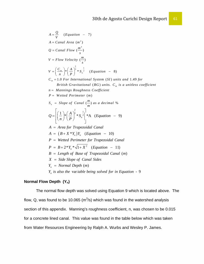
30th de Agosto Curichi Design Report 61
2
3
2132
( 7)
( )
( )
( )
* * ( 8)
1.0 ( ) 1.49
mo
m
QA EquationV
A Canal Area mmQ Canal FlowsmV Flow Velocitys
C AV S Equationn P
C For International System SI units and forBritish Gra
= −
=
=
=
⎛ ⎞ ⎛ ⎞= −⎜ ⎟⎜ ⎟⎝ ⎠⎝ ⎠
= ( ) .
( )
( ) %
m
o
vitational BG units C is a unitless coefficientn Mannings Roughness CoefficientP Wetted Perimeter m
mS Slope of Canal as a decimalm
==
=
( )
2132
2
1 * * *A ( 9)
* ( 10)
2* * 1 ( 11)
o
n n
n
AQ S Equationn P
A Area for Trapezoidal CanalA B X Y Y EquationP Wetted Perimeter for Trapezoidal Canal
P B Y X EquationB Le
⎡ ⎤⎛ ⎞ ⎛ ⎞⎢ ⎥= −⎜ ⎟ ⎜ ⎟⎢ ⎥⎝ ⎠ ⎝ ⎠⎣ ⎦=
= + −
=
= + + −= ( )
( ) var - 9
n
n
ngth of Base of Trapezoidal Canal mX Side Slope of Canal SidesY Normal Depth mY is also the iable being solved for in Equation
==
Normal Flow Depth (Yn)
The normal flow depth was solved using Equation 9 which is located above. The
flow, Q, was found to be 10.065 (m3/s) which was found in the watershed analysis
section of this appendix. Manning’s roughness coefficient, n, was chosen to be 0.015
for a concrete lined canal. This value was found in the table below which was taken
from Water Resources Engineering by Ralph A. Wurbs and Wesley P. James.

30th de Agosto Curichi Design Report 62
Table 2: Manning Roughness Values
Taken From Water Resources Engineering by Ralph A. Wurbs and Wesley P. James.
MANNING ROUGHNESS VALUES FOR OPEN CHANNELS
n Natural Channels
Clean, straight 0.025-0.033 Clean, irregular 0.033-0.045
Weedy, irregular 0.045-0.080 Brush, irregular 0.07-0.16
Floodplains Pasture, no brush 0.030-0.050 Brush, scattered 0.035-0.070
Brush, dense 0.070-0.15 Timber and brush 0.10-0.20
Excavated uniform earth channels Straight with short grass 0.02-0.03 Winding with short grass 0.025-0.035
Cobble, stony 0.03-0.05 Dense vegetation 0.05-0.12 Lined Channels
Concrete, finished 0.012-0.015 Gravel 0.02-0.03 Asphalt 0.015-0.02
Closed conduits (partially full) Steel, welded 0.010-0.015
Cast iron 0.011-0.016 Concrete 0.010-0.015
Corrugated metal 0.020-0.030
T.T.E. decided to use 3.8 m as a base width, B, for the canal, and a side slope,
X, of 2H:1V. The canal slope was determined on AutoCAD 2008 from the survey data
that was taken in Bolivia by T.T.E. The canal slope was also determined in AutoCAD
2008, and it was found to be .0016(m/m). Located below is Equation 12 for the Normal
Depth, Yn, of the trapezoidal canal.

30th de Agosto Curichi Design Report 63
( )( )( ) ( )( ) ( )( )
23
12
2
3.8 2110.065 * *.0016 * 3.8 2 ( - 12).015 3.8 2 * 1 2
1.11
n nn n
n
y yy y Equation
y
Y m
⎡ ⎤⎛ ⎞⎢ ⎥+⎜ ⎟⎛ ⎞⎢ ⎥= +⎜ ⎟ ⎜ ⎟⎢ ⎥⎝ ⎠ + +⎜ ⎟⎢ ⎥⎝ ⎠
⎣ ⎦=
Required Freeboard (FB)
The canal at the Curichi site has no restrictions on depth, but a Required
Freeboard calculation is still required. Freeboard calculations are required as a safety
factor to prevent waves or current from overflowing in the canal. Located in Equation 13
below is the associated calculation for Required Freeboard, FB.
0.5* ( - 13) ( )
( )
FB n
FB
n
FB C Y EquationFB Freeboard mC Coefficient of FreeboardY Normal Flow Depth m
=
==
=
0.50.6*1.11 0.63( ) ( - 14)FB m Equation= =
CFB is a coefficient that varies from 0.6 for small canals to 0.9 for larger canals
(Wurbs). T.T.E. chose a CFB of 0.6 due to the canal size for the Curichi site. A required
freeboard height was calculated to be 0.6 meters as shown in Equation 14 below.
Top Width (T)
In a trapezoidal canal, the most efficient design occurs when the base is the
same size as the water depth. T.T.E. chose a larger base width of 3.8 meters. The
normal flow depth, Yn, was found to be 1.11 meters and the total depth of the designed
canal was chosen to be 1.2 meters. Equation 15 below shows the calculation for the top
width, T, of the canal.

30th de Agosto Curichi Design Report 64
3.8 (2*2*1.11) 8.25 ( - 16)T m m Equation= + =
(2 * * ) ( - 15) ( ) ( )
( )
n
n
T B SS Y EquationT Top Width mB Base Width mSS Side SlopeY Calculated Normal Depth m
= +
====
A top width was calculated in Equation 16 below, and it was found that the top
width should be 8.25 meters wide. Due to space requirements at the Curichi site T.T.E.
was not able to select 8.25 meters as a top width for the canal. T.T.E. decided to use a
top width of 5 meters to accommodate space requirements for the road design on each
side of the canal at the Curichi site.
Flow Velocity (V)
With all the dimensions selected and calculated for the trapezoidal canal it was
possible to find the flow velocity, V, for the canal. Equation 17 below shows this
calculation.
( )( )( )( )
23
12
2
3 2*1.11 1.111 * *.0016 ( - 17)0.015 3 2*1.11 * 1 2
3.00
V Equation
mVs
⎛ ⎞+⎛ ⎞ ⎜ ⎟= ⎜ ⎟ ⎜ ⎟⎝ ⎠ + +⎜ ⎟⎝ ⎠
=
Froude Number (Fr)
The Froude Number must be below 0.6 to avoid standing waves in the canal.
Equation 18 below shows the required equation to calculate the Froude Number.
Equation 19 shows the required calculation for the trapezoidal canal that T.T.E. is
designing.
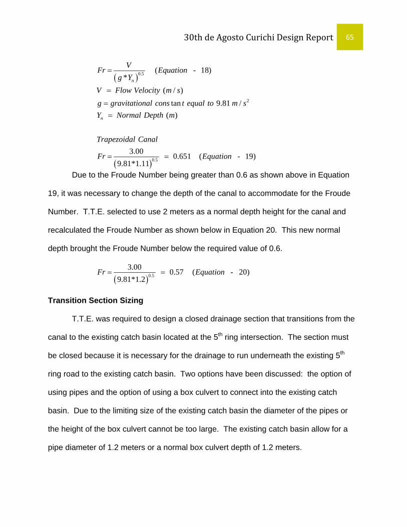
30th de Agosto Curichi Design Report 65
( )
( )
0.5
2
0.5
( - 18)*
( / ) tan 9.81 /
( )
3.00 0.651 ( - 19)
9.81*1.11
n
n
VFr Equationg Y
V Flow Velocity m sg gravitational cons t equal to m sY Normal Depth m
Trapezoidal Canal
Fr Equation
=
=
==
= =
Due to the Froude Number being greater than 0.6 as shown above in Equation
19, it was necessary to change the depth of the canal to accommodate for the Froude
Number. T.T.E. selected to use 2 meters as a normal depth height for the canal and
recalculated the Froude Number as shown below in Equation 20. This new normal
depth brought the Froude Number below the required value of 0.6.
( )0.53.00 0.57 ( - 20)
9.81*1.2Fr Equation= =
Transition Section Sizing
T.T.E. was required to design a closed drainage section that transitions from the
canal to the existing catch basin located at the 5th ring intersection. The section must
be closed because it is necessary for the drainage to run underneath the existing 5th
ring road to the existing catch basin. Two options have been discussed: the option of
using pipes and the option of using a box culvert to connect into the existing catch
basin. Due to the limiting size of the existing catch basin the diameter of the pipes or
the height of the box culvert cannot be too large. The existing catch basin allow for a
pipe diameter of 1.2 meters or a normal box culvert depth of 1.2 meters.

30th de Agosto Curichi Design Report 66
Pipe Sizing
The option of using pipes was considered to connect the canal to the existing
catch basin. Equation 21 below shows the pipe sizing calculations.
38
0.50
3.21* *# [ ] ( - 21)
* ( )
1 - Constant for SI units
m
m
Q nof PipesD Equation
C SD Pipe Diameter mQ Flown Mannings CoefficientC
=
====
Options of one, two, and three pipes were considered feasible, but Equations 22,
23, and 24 located below show that these dimensions are too large to connect to the
existing catch basin with the dimension height of 1.2 meters. Based on these
calculations it was determined that pipes will not work to connect to the existing catch
basin.
38
1 0.5
38
2 0.5
38
3 0.5
10.0653.21* *.0151[ ] 2.548 ( - 22)
1*.0016
10.0653.21* *.0152[ ] 1.96 ( - 23)
1*.0016
10.0653.21* *.0153[ ] 1.68 ( - 24)
1*.0016
D m Equation
D m Equation
D m Equation
= =
= =
= =
Box Culvert Sizing
Due to the option of the pipes not working T.T.E. explored the option of using a
box culvert to connect the designed canal to the existing catch basin. Equation 25

30th de Agosto Curichi Design Report 67
below shows the equation used to find the normal depth (Yn) of the rectangular box
culvert.
2 13 2
3
2
[( )*( ) * ]* ( - 25)
( )
1 ( ) ( ) ( / )
A = (3*Y ) P = (3 + 2*Y )
m
m
n n
C AQ S A Equationn P
mQ Flows
C for SI unitsn mannings coefficientA Area mP Wetted Perimeter mS Slope of Culvert m m
=
=
==
===
Equation 26 below shows the normal depth height of the designed box culvert
with a base of 3 meters. A base of 3 meters was chosen to match the base of the canal
for the maximum width of the box culvert. A normal height of 1.13 meters was found to
be the adequate depth of the box culvert. T.T.E. has chosen a box culvert depth of 1.2
meters to provide the largest possible flow into the existing catch basin.
2 13 23*110.065 [( )*( ) *.0016 ]*(3* ) ( - 26)
.015 3 2*1.13
nn
n
n
Y Y EquationY
Y m
=+
=
Outlet and Inlet Flow
Using Manning’s equation for outlet controlled culverts, Equation 27, and inlet
controlled culverts, Equation 28, it was possible to find the maximum flow through the
culverts.

30th de Agosto Curichi Design Report 68
2
* * * 2* * ( - 27)
( )
* * * 2* *( ) ( - 282
C C C L
P
P
C
L
C C O
C
Q N A C g H EquationN Number of Culverts
A Area of Culverts mC Loss CoefficientH Max Height of Head Loss from entrance to exit
DQ N A C g H Equation
A A
=
=
===
= −
= 2 ( ) icient
H Head (m)C
rea of Culvert Entrance mO Orfice Coeff==
)
CC can be found using Equation 29 and Equation 30.
0.5
2
423
( 1) ( - 29)
* *2* ( - 30)*
( )
, , ( )
C e f
e
f
Cf
m
C
C K K Equation
K Entrance CoefficientK Friction Loss Coefficient
L n gK EquationR C
L Culvert Length mAR Hydraulic Radius mP
−= + +
==
=
=
=
Ke is 0.7 for parallel flat edged entrances, CO is 0.7 for sharp edged entrances,
and the length of the culvert was found to be 11 m. This length of 11 meters was
selected to run the box culvert from the end of the canal just the distance under the
existing roadway at 5th ring. Using these variables T.T.E. was able to find the additional
values for the required inputs, Equation 31 and Equation 32, and resulting outlet and
inlet controlled flow rates, Equation 33 and Equation 34. The inlet controlled flow is not
adequate to handle the flow from the canal of 10.065 m3/s, but when the canal was

30th de Agosto Curichi Design Report 69
designed it was designed to handle the slight back up that may occur due to the
entrance controlled inlet of the box culvert.
2
2
423
0.5
3
11 *.0015 *2*9.81.0008 ( - 31)
3*1.2( ) *1.03 2*1.2
(0.7 .0008 1) .766 ( - 32)
1*(3.0*1.2)*.766* 2*9.81 *1.2 13.38 ( - 33)
f
C
Outlet
mmsK Equation
C Equation
m mQ Equation
−
= =
+
= + + =
= =
2
1*(3Inlet
s s
Q =3
2
1.2.0*1.2)*.7* 2*9.81 *(1.2 ) 9.46 ( - 34)2
m m Equations s
− =
The above calculations were repeated to accommodate for a box culvert section
that will run from the existing catch basin up the 16th radial to where the school begins.
The purpose of this is to keep children from playing in the canal. This service was
requested by the District 10 engineers as a design option.
22
423
0.5
3
2
211 *.0015 *2*9.81.016 ( - 31)
3*1.2( ) *1.03 2*1.2
(0.7 .0038 1) .763 ( - 32)
1*(3.0*1.2)*.763* 2*9.81 *1.2 13.32 ( - 33)
1*(3
f
C
Outlet
Inlet
mmsK Equation
C Equation
m mQ Equations s
Q
−
= =
+
= + + =
= =
=
3
2
1.2.0*1.2)*.7* 2*9.81 *(1.2 ) 9.46 ( - 34)2
m m Equations s
− =

30th de Agosto Curichi Design Report 70

30th de Agosto Curichi Design Report 71
Appendix D: Pavement Design

30th de Agosto Curichi Design Report 72

30th de Agosto Curichi Design Report 73
The roadway chosen for the T.T.E project was a non-reinforced concrete
pavement. In order to determine the thickness of the base and road surface, structural
design and fatigue calculations were made.
The fatigue calculation was done using equation 6.1 from Concrete Pavement
Design, Construction, and Performance, bert Delatte, Taylor and Francis: Nor
1
The pavement and the base for the Radial 16 would be similar to that of Radial 16
½. The values used for the structural calculations where extracted from the Radial 16 ½
project. Therefore the adopted layer for the road is:
• 12 cm base granular layer with a minimum CBR of 60% • 18 cm of rigid concrete pavement with no reinforcement • The 28th day characteristic strength of concrete (f’c) used for the concrete
pavement is 230 kg/cm2 (3271psi).
The values were extracted from Radial 16 ½ (5th Anillo –Av San Marten) provided by
the Director of Works for the city of Santa Cruz.
The adopted weight for design for this project is 11000 kg/axle. A factor of safety of
1.2 would be used to account for any loads exceeding the design load.
The calculated load P, = 1.2*11tons = 13.2tons
The Resources used for performing the structural design and fatigue calculations are:
• Concrete Pavement Design, Construction and Performance, Norbert Delatte, Taylor & Francis
• Proyecto Radial 16 ½ (5th Anillo av. San Marten • Traffic & Highway Engineering, Garber Hoel, 2nd Edition, PWS publishing

30th de Agosto Curichi Design Report 74

30th de Agosto Curichi Design Report 75
Appendix E: Cost Estimate

DRE002 SITE LAYOUT 1024 m 15.18
11612
OPEN CANAL + GRAVEL ROADCODE ACTIVITY QUANTITY UNITS COST MATERIALS DIRECT LABOR EQUIPMENT TOTAL COST (Bs.)
UNIT COST UNIT COST UNIT COST
MOBILIZATION AND SITE LAYOUTDRE001 MOBILIZATION (DRAINAGE) 1 GBL 4412.32 30,886
INS001 MOBILIZATION 1 GBL GBL 3150
AL350 MASON 11 HR HR 8.2
AL355 MASON HELPER 25 HR HR 6.5
PA0041 MOBILIZATION (Pavement) 1 GBL 4287.98 30,016MT001 EXTRA MATERIALS 1 GBL GBL 3000AL351 MASON 15 HR 8.2AL355 MASON HELPER 25 HR 6.5DRE002 SITE LAYOUT (SEWERS, CANALS, BRIDGES)(SEWERS, CANALS, BRIDGES) 1024 m 15.18 15,54215,542MA019 WOOD STAKES 2"X2"X30cm 124 PZA PZA 3PT002 PAINTING LATEX 3 GAL GAL 72HI001 INDENTED IRON 2.5 KG KG 12.72AL365 TOPOGRAPHER 10 HR HR 12AL366 RODMAN 30 HR HR 6
MQ002SURVEY EQUIPMENT 12 HR HR 40CHAIN SAW 12 HR HR 35
PA005 SITE LAYOUT (PAVEMENT) 1.024 KM 1821.05 12,747MA019 WOOD WEDGES 165 PZA PZA 60PT007 ALKYD BASE PAINT 0.4 L LITRES 30.5HI001 NAILS 1 KG KG 12.72AL365 TOPOGRAPHER 10 HR HR 12AL366 RODMAN 30 HR HR 6MQ022 SURVEY EQUIPMENT 12 HR HR 60PA0071** REMOVE & CLEAR RUBBLE 5,415(AL381) Dozer Operator 10 HR HR 10(MQ003) Dozer 10 HR HR 400AL355 ASSISTANT 10 HR HR 6.5
PAVEMENT & SITE CURBXC002EXC002 A H WO KEARTH WORK 11612 ^3m^3 159,092AL355 MASON ASSISTANT 120 HR HR 6.5AL361 EXCAVATOR OPERATOR 120 HR HR 6MQ007 EXCAVATOR 120 HR HR 200MQ009 DUMP TRUCK 120 HR HR 200ECX006 LEVEL AND COMPACT EXISTING GROUND 3484 m^3 100,261AL 360 SOIL COMPACTOR OPERATOR 40 HR 2.10HR 6HO 902 PLATE COMPACTOR 40 HR 0.1500HR 25PA029 PROVIDE AND PLACE CRUSHED BASE (15 cm) 2283.75 m^3 62.29 142,266AG015 CAPA BASE m^3 0.18HR 230AL385 OPERATOR HR 0.03HR 8.5AL362 ASSISTANT HR 0.02HR 6.5MQ001 BULLDOZER 120G HR 0.0081HR 284MQ028 VIBRATORY CONTRACTOR HR 0.0018HR 284MQ027 PNEUMATIC COMPACTOR HR 0.0018HR 284MQ004 WATER BEARER "AGUATERO" HR 0.0018HR 130PA016 CUT, DEM. AND REMOVE CONC. PAVEMENT 198 m^2 72 14,256AL385 OPERATOR HR 0.400HR 8.2AL350 LABORER HR 0.700HR 6.5AL355 ASSISTANT HR 0.500HR 8.5MQ019 PAVEMENT SAW HR 0.1800HR 50MQ009 BIGGER DUMP TRUCK HR 0.1200HR 200MQ002 FRONT ENTLOADER HR 0.2000HR 310PA047 GENERAL CLEANING 15360 m^2 1.06 16,234AL355 ASSISTANT HR 0.090HR 6.5
CANAL

DRE004 EXCAVATION WITH MACHINERY B/N F 39
PA042 EX. W/ MACHINERY + TRANSPORTATION 7652.04 m^3 31.94 244,406AL361 BACKHOE OPERATOR HR 0.050HR 6AL355 ASSISTANT HR 0.050HR 6.5AL354 FOREMAN HR 0.050HR 9MQ007 EXCAVATOR HR 0.050HR 200MQ009 BIGGER DUMP TRUCK HR 0.0720HR 200DRE005 MANUAL SLOPE SHAPING (SIDE & BOT.) 2748 m^2 5.12 14,078AL350 LABORER HR 0.180HR 8.2AL362 ASSISTANT HR 0.190HR 6.5DRE006 REIN. CONCR. LINING FOR CANAL: 20cm 5283.87 m^2 129.16 682,478AG901 CEMENT KG 26.00KG 0.94AG002 WASHED DEBRIS m^3 0.062m^ 140AG001 SAND m^3 0.050m^ 60MA004 CONSTRUCTION WOOD PIE2 0.040PIE 6.5HI001 NAIL KG 0.020KG 12.72AI004 ANTISOL L 0.200L 10.13HI002 REINFORCEMENT CORRUGATED REBAR KG 2.530KG 11.55HI003 MOORING WIRE KG 0.080KG 12.73AI003 GEOTEXTILE OP‐20 (200 g/m^2) m^2 0.300m^ 8AL363 OPERATOR OF LIGHT FIELD EQUIPMENT HR 0.040HR 6AL350 LABORER HR 0.950HR 8.2AL355 ASSISTANT HR 1.900HR 6.5HO901 MIXER OF 350 LTS HR 0.040HR 25DRE015 GRAVEL MATERIAL (STABILIZER) 1167.36 m^3 213.36 249,765AG002 CLEAN GRAVEL m^3 1.050m^ 140AL350 LABORER HR 1.000HR 8.2AL355 ASSISTANT HR 1.200HR 6.5DRE020 DRAINAGE PIPES FOR CANAL PVC 2" 1024 PZA 2.52 2,578HI003 REBAR TIE WIRE KG 0.200KGHS138 PVC PIPE m 0.0800mAL350 LABORER HR 0.0300HRAL355 ASSISTANT HR 0.0300HR
DEL. & PLAC. OF REIN. CONC. CULVERTS (4X3.70X2.30) 2 PZA 304631.3 609,263DRE002 REPLANTEO DE CANALS PUENTES 9.95 MLDRE003 EXCAVATION WITH MACHINERY S/N.F 59.69 M^3DRE004 EXCAVATION WITH MACHINERY B/N.F . 39.79.79 M^3M 3HOR0301 CONCRETE STRENGTH = 110 kg/c2 93.15 M^2HOR0355 HoAo of Sewer booth fck=210 kg/cm2 58.43 M^3HOR0353 HoAo of Sidewalk and curb fck=210 kg/cm2 3.28 M^3HOR0357 HoAo compress of sewer fck=210 kg/cm2 5.44 M^3DRE0031 refill and compact with plate. S/prov of material 24.05 M^3HIE018 Metallic Barandado F°G ° Ø 2 " 25.9 MHOR0356 HoAo Flagstone of approach fck=210 kg/cm2 4.05 M^3HOR0358 HoAo Losa de transicion fck=210 kg/cm2 8.33 M^3
BRIDGESPEDESTRIAN BRIDGE (L=11.8M) ‐ By School 1 PZA 19,797 19,797
DRE002 REPLANTEO DE CANALS PUENTES 11.8DRE003 EXCAVATION WITH MACHINERY S/N.F 2.94 M^3HOR0301 refill and compact with plate. S/prov of material 1.38HOR001 Zapatas de HoAo 0.56 M^3HOR002 Concrete: Columns of HoAo 0.17 M^3HOR0361 HoAo of Superstructure fck=210 kg/cm2 2.95 M^3HOR0362 HoAo of Diaphragm of stretch fck=210 kg/cm2 0.11 M^3HOR0363 HoAo of Diaphragm of support fck=210 kg/cm2 0.19 M^3HOR0011 Base of support bridge of HoAo 0.29 M^3HIE018 Metallic Barandado F°G ° Ø 2 " 23.6 M^3DRE0031 refill and compact with plate. S/prov of material 2.38 M^3HOR0356 HoAo Flagstone of approach fck=210 kg/cm2 0.54 M^3
ROADWAY CROSSING 3 PZA 240000 720,000.00TOTAL 3,069,080
3,069,000

UNIT COST UNIT COST UNIT COST
DRE001 MOBILIZATION (DRAINAGE) 1 GBL 4412.32 30,886
INS001 MOBILIZATION 1 GBL GBL 3150
AL350 MASON 11 HR HR 8.2
AL355 MASON HELPER 25 HR HR 6.5
PA0041 MOBILIZATION (Pavement) 1 GBL 4287.98 30,016MT001 EXTRA MATERIALS 1 GBL GBL 3000AL351 MASON 15 HR 8.2AL355 MASON HELPER 25 HR 6.5DRE002 SITE LAYOUT (SEWERS, CANALS, BRIDGES) 1024 m 15.18 15,542MA019 WOOD STAKES 2"X2"X30cm 124 PZA PZA 3PT002 PAINTING LATEX 3 GAL GAL 72HI001 INDENTED IRON 2.5 KG KG 12.72AL365 TOPOGRAPHER 10 HR HR 12AL366 RODMAN 30 HR HR 6
SURVEY EQUIPMENT 12 HR HR 40CHAIN SAW 12 HR HR 35
PA005 SITE LAYOUT (PAVEMENT) 1.024 KM 1821.05 12,747MA019 WOOD WEDGES 165 PZA PZA 60PT007 ALKYD BASE PAINT 0.4 L LITRES 30.5HI001 NAILS 1 KG KG 12.72AL365 TOPOGRAPHER 10 HR HR 12AL366 RODMAN 30 HR HR 6MQ022 SURVEY EQUIPMENT 12 HR HR 60
PA0071** REMOVE & CLEAR RUBBLE 5,415(AL381) Dozer Operator 10 HR HR 10(MQ003) Dozer 10 HR HR 400AL355 ASSISTANT 10 HR HR 6.5
EXC002 EARTH WORK 11612 m^3 159,092AL355 MASON ASSISTANT 120 HR HR 6.5AL361 EXCAVATOR OPERATOR 120 HR HR 6MQ007 EXCAVATOR 120 HR HR 200MQ009 DUMP TRUCK 120 HR HR 200ECX006 LEVEL AND COMPACT EXISTING GROUND 3484 m^3 100,261AL 360 SOIL COMPACTOR OPERATOR 40 HR 2.10HR 6HO 902 PLATE COMPACTOR 40 HR 0.1500HR 25PA029 PROVIDE AND PLACE CRUSHED BASE (15 cm) 1827 m^3 62.29 113,813AG015 CAPA BASE m^3 0.18HR 230AL385 OPERATOR HR 0.03HR 8.5AL362 ASSISTANT HR 0.02HR 6.5MQ001 BULLDOZER 120G HR 0.0081HR 284MQ028 VIBRATORY CONTRACTOR HR 0.0018HR 284MQ027 PNEUMATIC COMPACTOR HR 0.0018HR 284MQ004 WATER BEARER "AGUATERO" HR 0.0018HR 130PA015 DELIVERY & PLACEMENT OF ASPHALT CONC. 1827 m^3 2030.75 3,710,174AG026 CRUSHED SMALL AGGREGATE KG 1.320KG 175AG027 FINE TN 4 m^3 0.320m^3 68AG912 ASPHALT CEMENT m^3 140.00m^3 9AL354 FOREMAN HR 0.120HR 9AL355 ASSISTANT HR 0.850HR 6.5AL385 OPERATOR HR 0.420HR 6MQ029 ASPHALT PLANT HR 0.0560HR 900MQ030 ASPHALT CEMENT DISTRIBUTOR TANK HR 0.0560HR 300MQ031 GENERATOR HR 0.0550HR 122MQ002 FRONT ENDLOADER HR 0.0560HR 310MQ032 VIBRATORY PILE DRIVING HR 0.0350HR 243MQ032 5% MO HR 0.0350HR 243PA011 DELIVERY & PLACEMENT OF CURB 2030 m 68.52 139,096AG901 CEMENT KG 0.250KG 0.9AG001 RIVER SAND m^3 0.006m^3 60AG916 PREFABRICATED CORD m 1.000m 42AL354 FOREMAN HR 0.080HR 9AL350 LABORER HR 0.100HR 8.2AL355 ASSISTANT HR 6.5MQ009 BIGGER DUMP TRUCK HR 0.010HR 200PA016 CUT, DEMOLISH AND REMOVE CONC. PAVEMENT 198 m^2 72 14,256AL385 OPERATOR HR 0.400HR 8.2AL350 LABORER HR 0.700HR 6.5AL355 ASSISTANT HR 0.500HR 8.5MQ019 PAVEMENT SAW HR 0.1800HR 50MQ009 BIGGER DUMP TRUCK HR 0.1200HR 200MQ002 FRONT ENTLOADER HR 0.2000HR 310PA047 GENERAL CLEANING 1.554E+09 m^2 1.06 16,234AL355 ASSISTANT HR 0.090HR 6.5
OPEN CANAL + ASPHALT PAVEMENTACTIVITY QUANTITY UNITS MATERIALS EQUIPMENTCODE TOTAL COST (Bs.)COST DIRECT LABOR
PAVEMENT & SITE CURB
MOBILIZATION AND SITE LAYOUT
MQ002

PA042 EXCAVATION W/ MACHINERY + TRANSPORTATION 7652.04 m^3 31.94 244,406AL361 BACKHOE OPERATOR HR 0.050HR 6AL355 ASSISTANT HR 0.050HR 6.5AL354 FOREMAN HR 0.050HR 9MQ007 EXCAVATOR HR 0.050HR 200MQ009 BIGGER DUMP TRUCK HR 0.0720HR 200DRE005 MANUAL SLOPE SHAPING (SIDES & BOTTOM) 2748 m^2 5.12 14,078AL350 LABORER HR 0.180HR 8.2AL362 ASSISTANT HR 0.190HR 6.5DRE006 REIN. CONCRETE LINING FOR CANAL: 20cm 5283.87 m^2 129.16 682,478AG901 CEMENT KG 26.00KG 0.94AG002 WASHED DEBRIS m^3 0.062m^3 140AG001 SAND m^3 0.050m^3 60MA004 CONSTRUCTION WOOD PIE2 0.040PIE2 6.5HI001 NAIL KG 0.020KG 12.72AI004 ANTISOL L 0.200L 10.13HI002 REINFORCEMENT CORRUGATED REBAR KG 2.530KG 11.55HI003 MOORING WIRE KG 0.080KG 12.73AI003 GEOTEXTILE OP‐20 (200 g/m^2) m^2 0.300m^2 8AL363 OPERATOR OF LIGHT FIELD EQUIPMENT HR 0.040HR 6AL350 LABORER HR 0.950HR 8.2AL355 ASSISTANT HR 1.900HR 6.5HO901 MIXER OF 350 LTS HR 0.040HR 25DRE015 GRAVEL MATERIAL (STABILIZER) 1167.36 m^3 213.36 249,765AG002 CLEAN GRAVEL m^3 1.050m^3 140AL350 LABORER HR 1.000HR 8.2AL355 ASSISTANT HR 1.200HR 6.5DRE020 DRAINAGE PIPES FOR CANAL PVC 2" 1024 PZA 2.52 2,578HI003 REBAR TIE WIRE KG 0.200KGHS138 PVC PIPE m 0.0800mAL350 LABORER HR 0.0300HRAL355 ASSISTANT HR 0.0300HR
DELIVERY & PLAC. OF REIN. CONC. BOX CULVERTS (4X3.70X2.30) 2 PZA 304631.3 609,263DRE002 REPLANTEO DE CANALS PUENTES 9.95 MLDRE003 EXCAVATION WITH MACHINERY S/N.F 59.69 M^3DRE004 EXCAVATION WITH MACHINERY B/N.F 39.79 M^3HOR0301 CONCRETE STRENGTH = 110 kg/c2 93.15 M^2HOR0355 HoAo of Sewer booth fck=210 kg/cm2 58.43 M^3HOR0353 HoAo of Sidewalk and curb fck=210 kg/cm2 3.28 M^3HOR0357 HoAo compress of sewer fck=210 kg/cm2 5.44 M^3DRE0031 refill and compact with plate. S/prov of material 24.05 M^3HIE018 Metallic Barandado F°G ° Ø 2 " 25.9 MHOR0356 HoAo Flagstone of approach fck=210 kg/cm2 4.05 M^3HOR0358 HoAo Losa de transicion fck=210 kg/cm2 8.33 M^3
PEDESTRIAN BRIDGE (L=11.8M) ‐ By School 1 PZA 19,797 19,797DRE002 REPLANTEO DE CANALS PUENTES 11.8DRE003 EXCAVATION WITH MACHINERY S/N.F 2.94 M^3HOR0301 refill and compact with plate. S/prov of material 1.38HOR001 Zapatas de HoAo 0.56 M^3HOR002 Concrete: Columns of HoAo 0.17 M^3HOR0361 HoAo of Superstructure fck=210 kg/cm2 2.95 M^3HOR0362 HoAo of Diaphragm of stretch fck=210 kg/cm2 0.11 M^3HOR0363 HoAo of Diaphragm of support fck=210 kg/cm2 0.19 M^3HOR0011 Base of support bridge of HoAo 0.29 M^3HIE018 Metallic Barandado F°G ° Ø 2 " 23.6 M^3DRE0031 refill and compact with plate. S/prov of material 2.38 M^3HOR0356 HoAo Flagstone of approach fck=210 kg/cm2 0.54 M^3
ROADWAY CROSSING 3 PZA 240000 720,000.00TOTAL 6,889,897
6,890,000
CANAL
BRIDGES
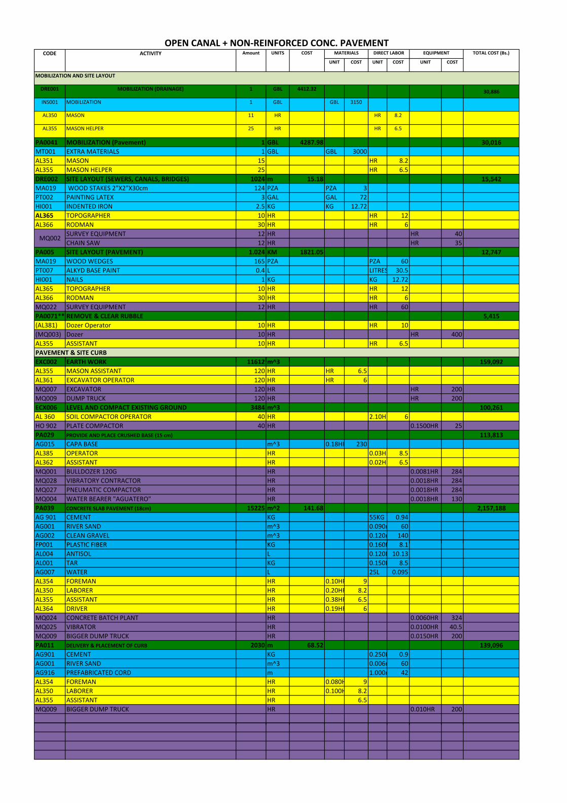
DRE002 SITE LAYOUT 1024 m 15.18
EXC002 EARTH WORK 11612 159 092
R
mm
FP001 PLASTIC FIBER KG 0 160KLK
RRRR
Kmm
HH
OPEN CANAL + NON‐REINFORCED CONC. PAVEMENTCODE ACTIVITY Amount UNITS COST MATERIALS DIRECT LABOR EQUIPMENT TOTAL COST (Bs.)
UNIT COST UNIT COST UNIT COST
MOBILIZATION AND SITE LAYOUT
DRE001 MOBILIZATION (DRAINAGE) 1 GBL 4412.32 30,886
INS001 MOBILIZATION 1 GBL GBL 3150
AL350 MASON 11 HR HR 8.2
AL355 MASON HELPER 25 HR HR 6.5
PA0041 MOBILIZATION (Pavement) 1 GBL 4287.98 30,016MT001 EXTRA MATERIALS 1 GBL GBL 3000AL351 MASON 15 HR 8.2AL355 MASON HELPER 25 HR 6.5DRE002 SITE LAYOUT (SEWERS, CANALS, BRIDGES)(SEWERS, CANALS, BRIDGES) 1024 m 15.18 15,54215,542MA019 WOOD STAKES 2"X2"X30cm 124 PZA PZA 3PT002 PAINTING LATEX 3 GAL GAL 72HI001 INDENTED IRON 2.5 KG KG 12.72AL365 TOPOGRAPHER 10 HR HR 12AL366 RODMAN 30 HR HR 6
MQ002SURVEY EQUIPMENT 12 HR HR 40CHAIN SAW 12 HR HR 35
PA005 SITE LAYOUT (PAVEMENT) 1.024 KM 1821.05 12,747MA019 WOOD WEDGES 165 PZA PZA 60PT007 ALKYD BASE PAINT 0.4 L LITRES 30.5HI001 NAILS 1 KG KG 12.72AL365 TOPOGRAPHER 10 HR HR 12AL366 RODMAN 30 HR HR 6MQ022 SURVEY EQUIPMENT 12 HR HR 60PA0071** REMOVE & CLEAR RUBBLE 5,415(AL381) Dozer Operator 10 HR HR 10(MQ003) Dozer 10 HR HR 400AL355 ASSISTANT 10 HR HR 6.5PAVEMENT & SITE CURBEXC002 EARTH WORK 11612 m^3m^3 159,092,AL355 MASON ASSISTANT 120 HR HR 6.5AL361 EXCAVATOR OPERATOR 120 HR HR 6MQ007 EXCAVATOR 120 HR HR 200MQ009 DUMP TRUCK 120 HR HR 200ECX006 LEVEL AND COMPACT EXISTING GROUND 3484 m^3 100,261AL 360 SOIL COMPACTOR OPERATOR 40 HR 2.10H 6HO 902 PLATE COMPACTOR 40 HR 0.1500HR 25PA029 PROVIDE AND PLACE CRUSHED BASE (15 cm) 113,813AG015 CAPA BASE m^3 0.18H 230AL385 OPERATOR HR 0.03H 8.5AL362 ASSISTANT HR 0.02H 6.5MQ001 BULLDOZER 120G HR 0.0081HR 284MQ028 VIBRATORY CONTRACTOR HR 0.0018HR 284MQ027 PNEUMATIC COMPACTOR HR 0.0018HR 284MQ004 WATER BEARER "AGUATERO" HR 0.0018HR 130PA039 CONCRETE SLAB PAVEMENT (18cm) 15225 m^2 141.68 2,157,188AG 901 CEMENT KG 55KG 0.94AG001 RIVER SAND m^3 0.090 60AG002 CLEAN GRAVEL m^3 0.120 140FP001 PLASTIC FIBER KG 0 160K. 8 18.1AL004 ANTISOL L 0.120 10.13AL001 TAR KG 0.150 8.5AG007 WATER L 25L 0.095AL354 FOREMAN HR 0.10H 9AL350 LABORER HR 0.20H 8.2AL355 ASSISTANT HR 0.38H 6.5AL364 DRIVER HR 0.19H 6MQ024 CONCRETE BATCH PLANT HR 0.0060HR 324MQ025 VIBRATOR HR 0.0100HR 40.5MQ009 BIGGER DUMP TRUCK HR 0.0150HR 200PA011 DELIVERY & PLACEMENT OF CURB 2030 m 68.52 139,096AG901 CEMENT KG 0.250 0.9AG001 RIVER SAND m^3 0.006 60AG916 PREFABRICATED CORD m 1.000 42AL354 FOREMAN HR 0.080 9AL350 LABORER HR 0.100 8.2AL355 ASSISTANT HR 6.5MQ009 BIGGER DUMP TRUCK HR 0.010HR 200

HHH
H
HHH
HH
KmmPKLKKm
HHH
mAL350 LABORER HR 000H 2
H
PEDESTRIAN BRIDGE (L=11 8M) By School 1 PZA 19 797 19 797
PA016 CUT, DEMOLISH AND REMOVE CONCR. PAVEMENT 198 m^2 72 14,256AL385 OPERATOR HR 0.400 8.2AL350 LABORER HR 0.700 6.5AL355 ASSISTANT HR 0.500 8.5MQ019 PAVEMENT SAW HR 0.1800HR 50MQ009 BIGGER DUMP TRUCK HR 0.1200HR 200MQ002 FRONT ENTLOADER HR 0.2000HR 310PA047 GENERAL CLEANING 15360 m^2 1.06 16,234AL355 ASSISTANT HR 0.090 6.5CANALPA042 EXCA. W/ MACHINERY + TRANSPORTATION 7652.04 m^3 31.94 244,406AL361 BACKHOE OPERATOR HR 0.050 6AL355 ASSISTANT HR 0.050 6.5AL354 FOREMAN HR 0.050 9MQ007 EXCAVATOR HR 0.050HR 200MQ009Q BIGGER DUMP TRUCK HR 0.0720HR 200DRE005 MANUAL SLOPE SHAPING (SIDES & BOTTOM) 2748 m^2 5.12 14,078AL350 LABORER HR 0.180 8.2AL362 ASSISTANT HR 0.190 6.5DRE006 REIN. CONCRETE LINING FOR CANAL: 20cm 6639 m^2 129.16 857,495AG901 CEMENT KG 26.00 0.94AG002 WASHED DEBRIS m^3 0.062 140AG001 SAND m^3 0.050 60MA004 CONSTRUCTION WOOD PIE2 0.040 6.5HI001 NAIL KG 0.020 12.72AI004 ANTISOL L 0.200 10.13HI002 REINFORCEMENT CORRUGATED REBAR KG 2.530 11.55HI003 MOORING WIRE KG 0.080 12.73AI003 GEOTEXTILE OP‐20 (200 g/m^2) m^2 0.300 8AL363 OPERATOR OF LIGHT FIELD EQUIPMENT HR 0.040 6AL350 LABORER HR 0.950 8.2AL355 ASSISTANT HR 1.900 6.5HO901 MIXER OF 350 LTS HR 0.040HR 25DRE015 GRAVEL MATERIAL (STABILIZER) 1167.36 m^3 213.36 249,765AG002 CLEAN GRAVEL m^3 1.050 140AL350 LABORER HR 1.000H1. 8.28.AL355 ASSISTANT HR 1.200 6.5DRE020 DRAINAGE PIPES FOR CANAL PVC 2" 1024 PZA 2.52 2,578HI003 REBAR TIE WIRE KG 0.200KGHS138 PVC PIPE m 0.0800mAL350 LABORER HR 0.0300HRAL355 ASSISTANT HR 0.0300HR
DEL. & PLAC. REIN. CONC. CULVERTS (4X3.70X2.30) 2 PZA 304631.33 609,263DRE002 REPLANTEO DE CANALS PUENTES 9.95 MLDRE003 EXCAVATION WITH MACHINERY S/N.F 59.69 M^3DRE004 EXCAVATION WITH MACHINERY B/N.F 39.79 M^3HOR0301 CONCRETE STRENGTH = 110 kg/c2 93.15 M^2HOR0355 HoAo of Sewer booth fck=210 kg/cm2 58.43 M^3HOR0353 HoAo of Sidewalk and curb fck=210 kg/cm2 3.28 M^3HOR0357 HoAo compress of sewer fck=210 kg/cm2 5.44 M^3DRE0031 refill and compact with plate. S/prov of material 24.05 M^3HIE018 Metallic Barandado F°G ° Ø 2 " 25.9 MHOR0356 HoAo Flagstone of approach fck=210 kg/cm2 4.05 M^3HOR0358 HoAo Losa de transicion fck=210 kg/cm2 8.33 M^3BRIDGES
PEDESTRIAN BRIDGE (L=11 8M) ‐ By School . ‐ 1 PZA 19 797, 19 797,DRE002 REPLANTEO DE CANALS PUENTES 11.8DRE003 EXCAVATION WITH MACHINERY S/N.F 2.94 M^3HOR0301 refill and compact with plate. S/prov of material 1.38HOR001 Zapatas de HoAo 0.56 M^3HOR002 Concrete: Columns of HoAo 0.17 M^3HOR0361 HoAo of Superstructure fck=210 kg/cm2 2.95 M^3HOR0362 HoAo of Diaphragm of stretch fck=210 kg/cm2 0.11 M^3HOR0363 HoAo of Diaphragm of support fck=210 kg/cm2 0.19 M^3HOR0011 Base of support bridge of HoAo 0.29 M^3HIE018 Metallic Barandado F°G ° Ø 2 " 23.6 M^3DRE0031 refill and compact with plate. S/prov of material 2.38 M^3HOR0356 HoAo Flagstone of approach fck=210 kg/cm2 0.54 M^3
ROADWAY CROSSING 3 PZA 240000 720,000.00TOTAL 5,511,928
5,512,000

MA019 WOOD STAKES 2"X2"X30cm 124 PZA PZA 3
^^
AG007 WATER L 25L 0 095
^
H
MQ009 BIGGER DUMP TRUCK HR 0 1200 200
PARTIAL‐COVERED CANAL + NON‐REINFORCED CONCRETE PAVEMENTCODE ACTIVITY QUANTITY UNITS COST MATERIALS DIRECT LABOR EQUIPMENT TOTAL COST (Bs.)
UNIT COST UNIT COST UNIT COST
MOBILIZATION AND SITE LAYOUTDRE001 MOBILIZATION (DRAINAGE) 1 GBL 4412.32 30,886
INS001 MOBILIZATION 1 GBL GBL 3150
AL350 MASON 11 HR HR 8.2
AL355 MASON HELPER 25 HR HR 6.5
PA0041 MOBILIZATION (Pavement) 1 GBL 4287.98 30,016MT001 EXTRA MATERIALS 1 GBL GBL 3000AL351 MASON 15 HR 8.2AL355 MASON HELPER 25 HR 6.5DRE002 SITE LAYOUT (SEWERS, CANALS, BRIDGES) 1024 m 15.18 15,542MA019 WOOD STAKES 2"X2"X30cm 124 PZA PZA 3PT002 PAINTING LATEX 3 GAL GAL 72HI001 INDENTED IRON 2.5 KG KG 12.72AL365 TOPOGRAPHER 10 HR HR 12AL366 RODMAN 30 HR HR 6
MQ002SURVEY EQUIPMENT 12 HR HR 40CHAIN SAW 12 HR HR 35
PA005 SITE LAYOUT (PAVEMENT) 1.024 KM 1821.05 12,747MA019 WOOD WEDGES 165 PZA PZA 60PT007 ALKYD BASE PAINT 0.4 L LITRES 30.5HI001 NAILS 1 KG KG 12.72AL365 TOPOGRAPHER 10 HR HR 12AL366 RODMAN 30 HR HR 6MQ022 SURVEY EQUIPMENT 12 HR HR 60PA0071** REMOVE & CLEAR RUBBLE 5,415(AL381) Dozer Operator 10 HR HR 10(MQ003) Dozer 10 HR HR 400AL355 ASSISTANT 10 HR HR 6.5
PAVEMENT & SITE CURBEXC002 EARTH WORK 11612 m^3 159,092AL355 MASON ASSISTANT 120 HR HR 6.5AL361 EXCAVATOR OPERATOR 120 HR HR 6MQ007 EXCAVATOR 120 HR HR 200MQ009 DUMP TRUCK 120 HR HR 200ECX006 LEVEL AND COMPACT EXISTING GROUND 3484 m^3 100,261AL 360 SOIL COMPACTOR OPERATOR 40 HR 2.10HR 6HO 902 PLATE COMPACTOR 40 HR 0.1500 25PA029 PROV. AND PLAC CRUSHED BASE (15 cm) 113,813AG015 CAPA BASE m^3 0.18HR 230AL385 OPERATOR HR 0.03HR 8.5AL362 ASSISTANT HR 0.02HR 6.5MQ001 BULLDOZER 120G HR 0.0081 284MQ028 VIBRATORY CONTRACTOR HR 0.0018 284MQ027 PNEUMATIC COMPACTOR HR 0.0018 284MQ004 WATER BEARER "AGUATERO" HR 0.0018 130PA039 CONCRETE SLAB PAVEMENT (18cm) 15225 m^2 141.68 2,157,188AG 901 CEMENT KG 55KG 0.94AG001 RIVER SAND m^3 0.090m 60AG002 CLEAN GRAVEL m^3 0.120m 140FP001 PLASTIC FIBER KG 0.160KG 8.1AL001 TAR KG 0.150KG 8.5AG007 WATER L 25L 0 095.AL354 FOREMAN HR 0.10HR 9AL350 LABORER HR 0.20HR 8.2AL355 ASSISTANT HR 0.38HR 6.5AL364 DRIVER HR 0.19HR 6MQ024 CONCRETE BATCH PLANT HR 0.0060 324MQ025 VIBRATOR HR 0.0100 40.5MQ009 BIGGER DUMP TRUCK HR 0.0150 200PA011 DELIVERY & PLACEMENT OF CURB 2030 m 68.52 139,096AG901 CEMENT KG 0.250KG 0.9AG001 RIVER SAND m^3 0.006m 60AG916 PREFABRICATED CORD m 1.000m 42AL354 FOREMAN HR 0.080HR 9AL350 LABORER HR 0.100HR 8.2AL355 ASSISTANT HR 6.5MQ009 BIGGER DUMP TRUCK HR 0.010 200PA016 CUT, DEMO. AND REMOVE CONC. PAVEMENT 198 m^2 72 14,256AL385 OPERATOR HR 0.400HR 8.2AL350 LABORER HR 0.700HR 6.5AL355 ASSISTANT HR 0.500HR 8.5MQ019 PAVEMENT SAW HR 0.1800 50MQ009 BIGGER DUMP TRUCK HR 0 1200. 200MQ002 FRONT ENTLOADER HR 0.2000 310PA047 GENERAL CLEANING 15360 m^2 1.06 16,234AL355 ASSISTANT HR 0.090HR 6.5

H
^^E
AI004 ANTISOL L
^
H
^
DRE0031 refill and compact plate S/pro of material M^3
CANALPA042 EX. W/ MACHINERY + TRANSPORTATION 7652.04 m^3 31.94 244,406AL361 BACKHOE OPERATOR HR 0.050HR 6AL355 ASSISTANT HR 0.050HR 6.5AL354 FOREMAN HR 0.050HR 9MQ007 EXCAVATOR HR 0.050 200MQ009 BIGGER DUMP TRUCK HR 0.0720 200DRE005 MAN. SLOPE SHAPING (SIDE & BOT.) 2748 m^2 5.12 14,078AL350 LABORER HR 0.180HR 8.2AL362 ASSISTANT HR 0.190HR 6.5DRE006 REIN. CONC. LINING FOR CANAL: 20cm 5283.87 m^2 129.16 682,478AG901 CEMENT KG 26.00KG 0.94AG002 WASHED DEBRIS m^3 0.062m 140AG001 SAND m^3 0.050m 60MA004 CONSTRUCTION WOOD PIE2 0.040PI 6.5HI001 NAIL KG 0.020KG 12.72AI004 ANTISOL L 0 200L0.200L 10 12510.125HI002 REINFORCEMENT CORRUGATED REBAR KG 2.530KG 11.55HI003 MOORING WIRE KG 0.080KG 12.73AI003 GEOTEXTILE OP‐20 (200 g/m^2) m^2 0.300m 8AL363 OPERATOR OF LIGHT FIELD EQUIPMENT HR 0.040HR 6AL350 LABORER HR 0.950HR 8.2AL355 ASSISTANT HR 1.900HR 6.5HO901 MIXER OF 350 LTS HR 0.040 25DRE015 GRAVEL MATERIAL (STABILIZER) 1167.36 m^3 213.36 249,765AG002 CLEAN GRAVEL m^3 1.050m 140AL350 LABORER HR 1.000HR 8.2AL355 ASSISTANT HR 1.200HR 6.5DRE020 DRAINAGE PIPES FOR CANAL PVC 2" 1024 PZA 2.52 2,578HI003 REBAR TIE WIRE KG 0.200KGHS138 PVC PIPE m 0.0800mAL350 LABORER HR 0.0300HRAL355 ASSISTANT HR 0.0300HR
DEL. & PLAC. REIN. CONC. CULVERTS (4X3.70X2.30) 52 PZA 304631.33 15,840,829DRE002 REPLANTEO DE CANALS PUENTES 9.95 MLDRE003 EXCAVATION WITH MACHINERY S/N.F 59.69 M^3DRE004 EXCAVATION WITH MACHINERY B/N.F 39.79 M^3HOR0301 CONCRETE STRENGTH = 110 kg/c2 93.15 M^2HOR0355 HoAo of Sewer booth fck=210 kg/cm2 58.43 M^3HOR0353 HoAo of Sidewalk and curb fck=210 kg/cm2 3.28 M^3HOR0357 HoAo compress of sewer fck=210 kg/cm2 5.44 M^3DRE0031 refill and compact with plate. S/prov of material 24.05 M^3HIE018 Metallic Barandado F°G ° Ø 2 " 25.9 MHOR0356 HoAo Flagstone of approach fck=210 kg/cm2 4.05 M^3HOR0358 HoAo Losa de transicion fck=210 kg/cm2 8.33 M^3
BRIDGESPEDESTRIAN BRIDGE (L=11.8M) ‐ By School 1 PZA 19,797
DRE002 REPLANTEO DE CANALS PUENTES 11.8DRE003 EXCAVATION WITH MACHINERY S/N.F 2.94 M^3HOR0301 refill and compact with plate. S/prov of material 1.38HOR001 Zapatas de HoAo 0.56 M^3HOR002 Concrete: Columns of HoAo 0.17 M^3HOR0361 HoAo of Superstructure fck=210 kg/cm2 2.95 M^3HOR0362 HoAo of Diaphragm of stretch fck=210 kg/cm2 0.11 M^3HOR0363 HoAo of Diaphragm of support fck=210 kg/cm2 0.19 M^3HOR0011 Base of support bridge of HoAo 0.29 M^3HIE018 Metallic Barandado F°G ° Ø 2 " 23.6 M^3DRE0031 refill and compact with plate S/prov of material with . v 2 382.38 M^3HOR0356 HoAo Flagstone of approach fck=210 kg/cm2 0.54 M^3
ROADWAY CROSSING 3 PZA 240000 720,000.00TOTAL 20,548,680
20,549,000

ID Task Name Duration Start Finish
1 Concrete Lined Canal 126 days Mon 3/2/09 Mon 8/24/092 Mobilization 3 days Mon 3/2/09 Wed 3/4/093 Site Clearing 4 days Thu 3/5/09 Tue 3/10/094 Site Layout 9 days Wed 3/11/09 Mon 3/23/095 Canal Excavation and Compaction of fill Section 25 days Tue 3/24/09 Mon 4/27/096 Sloping Shaping 21 days Tue 3/31/09 Tue 4/28/097 Placement of Gravel - Stabilizer 7 days Mon 4/6/09 Tue 4/14/098 Placement of Reinforced Concrete lining 90 days Wed 4/15/09 Tue 8/18/099 Pedestrian and Vehicle Bridges 64 days Wed 4/22/09 Mon 7/20/0910 Clean-up 2 days Wed 8/19/09 Thu 8/20/0911 Demobilization 2 days Fri 8/21/09 Mon 8/24/091213 PAVEMENT 93 days Mon 3/30/09 Wed 8/5/0914 Mobilization 3 days Mon 3/30/09 Wed 4/1/0915 Site Layout 6 days Thu 4/2/09 Thu 4/9/0916 Pavement Earthwork 7 days Fri 4/10/09 Mon 4/20/0917 Place and Compact Base - Roadway 1 14 days Tue 4/21/09 Fri 5/8/0918 Placement of Curb - Roadway 1 17 days Tue 4/28/09 Wed 5/20/0919 Placement of Concrete Pavement - Roadway 1 21 days Mon 5/18/09 Mon 6/15/0920 Place and Compact Base - Roadway 2 14 days Tue 6/9/09 Fri 6/26/0921 Placement of Curb - Roadway 2 17 days Mon 6/22/09 Tue 7/14/0922 Placement of Concrete Pavement - Roadway 2 21 days Thu 7/2/09 Thu 7/30/0923 Clean-up 2 days Fri 7/31/09 Mon 8/3/0924 Demobilization 2 days Tue 8/4/09 Wed 8/5/09
Dozer,ChainsawSuvey Equipment,Chainsaw
Excavator,Big Dump Truck,Pnuematic Compactor,Vibrating Compactor
Grader,Vibrating Compactor,Pnuematic Compactor,Water TruckCocret
Concrete batch Plant,Wat
Suvey Equipment,ChainsawDozer
Dozer,Pnuematic CompactorCocrete Batch Plant,Big Dump Truck,Vibrator
Cocrete Batch Plant,Big Dump Truck,VibratorDozer,Pnuematic Compactor
Cocrete Batch Plant,Big DumCocrete Batch Plan
Nov Dec Jan Feb Mar Apr May Jun Jul AugQtr 1, 2009 Qtr 2, 2009 Qtr 3, 2009
Task
Progress
Milestone
Summary
Rolled Up Task
Rolled Up Milestone
Rolled Up Progress
Split
External Tasks
Project Summary
Group By Summary
Deadline
Page 1
Project: 30th de Agosto.mppDate: Tue 11/4/08