radiation-driven flame weakening effects in sooting turbulent diffusion flames
TRANSCRIPT
Available online at www.sciencedirect.comProceedings
Proceedings of the Combustion Institute 32 (2009) 1481–1489
www.elsevier.com/locate/proci
of the
CombustionInstitute
Radiation-driven flame weakening effectsin sooting turbulent diffusion flames
Praveen Narayanan a, Arnaud Trouve a,b,*
a Department of Mechanical Engineering, University of Maryland, College Park, MD 20742, USAb Department of Fire Protection Engineering, University of Maryland, College Park, MD 20742, USA
Abstract
The objective of the present study is to use detailed numerical modeling to bring basic informationon the structure of turbulent non-premixed flames under sooting and radiating conditions. Thequestions of flame weakening, flame extinction, and soot leakage are studied using direct numericalsimulation. Simulations of ethylene–air combustion are performed in both a reference laminar coun-ter-flow flame configuration and a momentum-driven turbulent wall-flame configuration. In the turbu-lent wall-flame configuration, the flame optical thickness is artificially increased in order to magnifythe role played by luminous thermal radiation. The resulting optically thickened flames featurefrequent and pronounced low-temperature, low-burning-intensity spots that may be interpreted asquasi-flame extinction events. The data analysis reveals that these flame weakening events are similarto radiation extinction phenomena previously observed in microgravity laminar flames, and are asso-ciated with low values of the fuel–air mixing rate and large values of the flame radiant fraction.These events also differ from previously made observations to the extent that they are associated withsoot mass leakage across the flame and occur under a broader range of flame stretch conditions,thereby suggesting that turbulent flames are more susceptible to radiation extinction than their lam-inar counterparts.� 2009 The Combustion Institute. Published by Elsevier Inc. All rights reserved.
Keywords: Turbulent non-premixed combustion; Thermal radiation; Radiation extinction; Soot; Direct numericalsimulation
1. Introduction
Thermal radiation transport plays an impor-tant role in many non-premixed combustion sys-tems [1–3]. However, the mechanisms through
1540-7489/$ - see front matter � 2009 The Combustion Institdoi:10.1016/j.proci.2008.06.056
* Corresponding author. Address: Department of FireProtection Engineering, University of Maryland, Col-lege Park, MD 20742, USA. Fax: +1 301 405 9383.
E-mail address: [email protected] (A. Trouve).
which radiant emissions affect the flame structureare not fully understood. Basic laminar diffusionflame studies reveal that radiative effects becomesignificant under conditions corresponding tolow values of the fuel–air mixing rate (i.e. lowvalues of flame stretch) [4,5]. Under low-flamestretch conditions, the effects of thermal radia-tion are to decrease the net heat production rateand flame temperature, and sufficient levels ofradiative cooling will result in sub-critical burn-ing rates and consequent flame extinction. Thus,laminar diffusion flame theory considers two
ute. Published by Elsevier Inc. All rights reserved.
1482 P. Narayanan, A. Trouve / Proceedings of the Combustion Institute 32 (2009) 1481–1489
different limits for flame extinction: extinctionwill occur as a result of excessively high valuesof the rate of fuel–air mixing, i.e. insufficient res-idence times to complete the combustion pro-cesses [6–8]; extinction will also occur as aresult of excessively low values of the rate offuel–air mixing, i.e. under sluggish combustionconditions that are vulnerable to radiative cool-ing [4,5,9–18]. The low (high) scalar dissipationrate limit is called radiation (kinetic) extinction.
Radiation extinction has been studied overthe past two decades in several laminar diffusionflame configurations, including solid fuel stagna-tion-point flames [5], spherical flames aroundliquid fuel droplets [4,5,10,15], and spherical orplanar gaseous fuel flames [5,9,11–14,16–18].Previous studies show that thermal radiation isresponsible for extinction phenomena occurringin both weakly strained planar and weaklycurved spherical diffusion flames. While a gen-eric extinction criterion has not been clearlyarticulated, many studies point out that radia-tion extinction is associated with large valuesof the flame radiant fraction (defined as the spa-tially averaged net radiative power divided bythe spatially averaged combustion heat releaserate). Values of the flame radiant fraction aslarge as 60–80% are reported in Refs. [9,10,12].Such large values are possible at sufficientlylow values of flame stretch because of the signif-icant decrease in combustion intensity thatoccurs in response to slower fuel–air mixingconditions.
Consistent with low combustion intensities,several studies indicate that the flame tempera-tures at the radiation extinction limit may bequite low, as low as 1100–1300 K [4,5,9,10,12,18]. At these low temperatures, the laminarflames become blue-colored and soot-free, andextinction is driven by radiant emissions fromgaseous species (CO2 and H2O). Note that theabsence of soot in these recent examples ofradiation extinction should be interpreted withcaution. In other configurations, the role of sootmay become dominant, as suggested by previousstudies of laminar or turbulent, smoking jetdiffusion flames in which soot mass leakageacross the tip of the flame is often presented asa consequence of radiative cooling (i.e. as aradiation extinction event) [19,20]. We also referthe reader to Ref. [21] for a recent analysis ofsoot mass emissions from luminous turbulent dif-fusion flames.
Previous studies also suggest that the lowcombustion intensity conditions required nearthe radiation extinction limit may be achievedin a number of different ways, for instance inweakly stretched microgravity (lg) flames or instrongly diluted or strongly sooting earth-gravity(1 g) flames. While lg-conditions are not a priori
required, to date, fundamental observations ofradiation extinction in liquid or gaseous fuellaminar diffusion flames have been mostly lim-ited to microgravity experiments [5,10,13, 15,17,18]. The implications of these results to 1 g-flames in general, and to turbulent combustionapplications in particular remain entirely openquestions.
The objective of the present study is to usedirect numerical simulation (DNS) to examineradiation-driven flame weakening effects in turbu-lent non-premixed flames that are both stronglysooting and radiating. The numerical configura-tion corresponds to a wall-flame and this studyis a continuation of previous work on boundarylayer combustion presented in Ref. [22]. Note,however, that the flame-wall distance has beenincreased in the present set of simulations and thatthe presence of the wall is not central to the dis-cussion below. The DNS solver and modelingchoices are described in Section 2. Resultsobtained in a preliminary laminar flame studyare presented in Section 3.1, while results obtainedin the turbulent wall-flame study are presented inSection 3.2.
2. Direct numerical simulation solver
The present study is performed using anadvanced DNS solver called S3D [23]. S3D is afully compressible Navier–Stokes solver coupledwith an integrator for combustion chemistry,and is based on 8th-order finite differencing[24,25], 4th-order explicit Runge–Kutta timeintegration [26], a characteristic-based boundaryconditions treatment [27–31], a CHEMKIN-com-patible description of chemical kinetics [32], anda conventional rectangular Cartesian mesh capa-bility. In addition, S3D is a massively parallelsolver based on Message Passage Interface proto-cols and features excellent scalability perfor-mance [23].
The selected combustion system correspondsto ethylene burning in air. While S3D featuresa detailed chemistry capability, combustion isdescribed in the present study using a single-step model proposed in Ref. [33]. Additionalflame modeling choices include: a constant heatcapacity, cp � 1006 J � kg�1 � K�1; a tempera-ture-dependent dynamic viscosity (l varies likeT0.7); a constant Prandtl number, Pr = 0.708;and unity Lewis numbers (see Ref. [22] fordetails).
Soot formation is described using a phenome-nological modeling strategy previously developedby Moss et al. [34–37] and Lindstedt et al. [38–40]. The strategy consists in solving two transportequations for soot mass fraction Ys and soot num-ber density n:
oðqY sÞot þ oðqY suiÞ
oxi¼ � o
oxiðqY sV t;iÞ þ o
oxj
lSc
oY s
oxj
� �þ _x000s
oot
nN 0
� �þ o
oxi
nN 0
ui
� �¼ � o
oxi
nN 0
V t;i
� �þ o
oxj
lqSc
ooxj
nN 0
� �� �þ _x000n
9>>=>>;
ð1Þ
P. Narayanan, A. Trouve / Proceedings of the Combustion Institute 32 (2009) 1481–1489 1483
where q is the mixture mass density; ui (Vt,i) thexi-component of the flow (thermophoretic) veloc-ity vector; N0 the Avogadro number; _x000s the netreaction rate for soot mass; and _x000n the net pro-duction rate for soot number density. The secondterm on the RHS of Eq. (1) is a diffusive termadded for numerical stability; we use Sc = 300.Thermophoresis transport is described in Eq. (1)using a classical expression from the kinetic the-ory of gases: Vt,i = �0.54(l/q)o/oxi(ln(T)), whereT is temperature. The model expressions for _x000sand _x000n incorporate semi-empirical descriptionsof important physical and chemical soot pro-cesses, e.g. particle inception, surface growth,oxidation, and coagulation [34–40]. These expres-sions are also based on a number of simplifyingassumptions, for instance the model ignores therole of soot precursors and assumes a mono-dis-persed soot particle size distribution. In addition,because it is combined with single-step chemistry,the model adopts ethylene as the controlling spe-cies for soot inception and O2 as that for soot oxi-dation. Model coefficients are taken from Ref.[36].
Thermal radiation transport is described usinga classical approach in which the radiation inten-sity I is treated as a function of both spatial loca-tion and angular directions and is obtained as asolution of the radiative transfer equation (RTE)for an absorbing–emitting medium [41,42]:
dIds¼ j
rT 4
p
� �� jI ð2Þ
where s is distance along a particular ray; j themean absorption coefficient of the medium (inunits of m�1); and r is the Stefan–Boltzmannconstant. The radiative power density (i.e. theradiation term in the energy equation) is thenobtained as the integral of the LHS of Eq. (2) overangular space: _q000r ¼
R4pðdI=dsÞdX, where dX des-
ignates an elementary solid angle.Additional radiation modeling choices include
the assumption of a non-scattering medium andthat of gray properties. The mean absorptioncoefficient is expressed in terms of contributionsdue to CO2, H2O and soot [41,42]:
j ¼ pðxCO2aCO2
þ xH2OaH2OÞ þ js
js ¼ C � fvT
�ð3Þ
where p is pressure (atm); xk the species k molefraction; ak the Planck mean absorption coeffi-cient of species k (m�1 � atm�1); js the meanabsorption coefficient of soot (m�1); and C a mod-
el coefficient. ak is described using temperature-dependent curve-fit expressions given in Ref.[43]. js is described as proportional to the productof temperature times the soot volume fraction fv,fv = (qYs/qs) with qs the soot mass density, qs =1800 kg � m�3 [41,42]; we use C = 700 m�1 �K�1.
Equation (2) is solved using the discrete trans-fer method (DTM) originally proposed by Lock-wood and Shah [44]. DTM is a ray-tracingapproach in which: the RTE is first integratedanalytically along straight rays that are represen-tative of radiation transport in elementary angularregions; the radiation field is then calculated as asolution of an elliptic system through a successionof iterative sweeps; and a simple projection algo-rithm is finally applied to transform the radiationfield from a ray-based solution to a Eulerian grid-based solution compatible with the flow and com-bustion solver [44]. In DTM, precision is con-trolled by changing the angular discretization, i.ethe number of rays Nh and N/ used to dividethe polar and azimuthal coordinates system; weuse Nh = 8 and N/ = 17. A sub-cycling scheme isalso adopted in which the DTM solver is calledonce every 200 compressible flow time steps. Withthis scheme, the overhead associated with the cal-culation of thermal radiation transport is approx-imately 30%.
3. DNS results
Results presented in this section have beenobtained using 16 processors on a Cray XT/AMD Opteron system (Section 3.1) or 32 proces-sors on an IBM p575 Power 5 system (Section3.2); both systems are operated by the NationalEnergy Research Scientific Computing Center atLawrence Berkeley Laboratory.
3.1. Laminar counter-flow diffusion flames
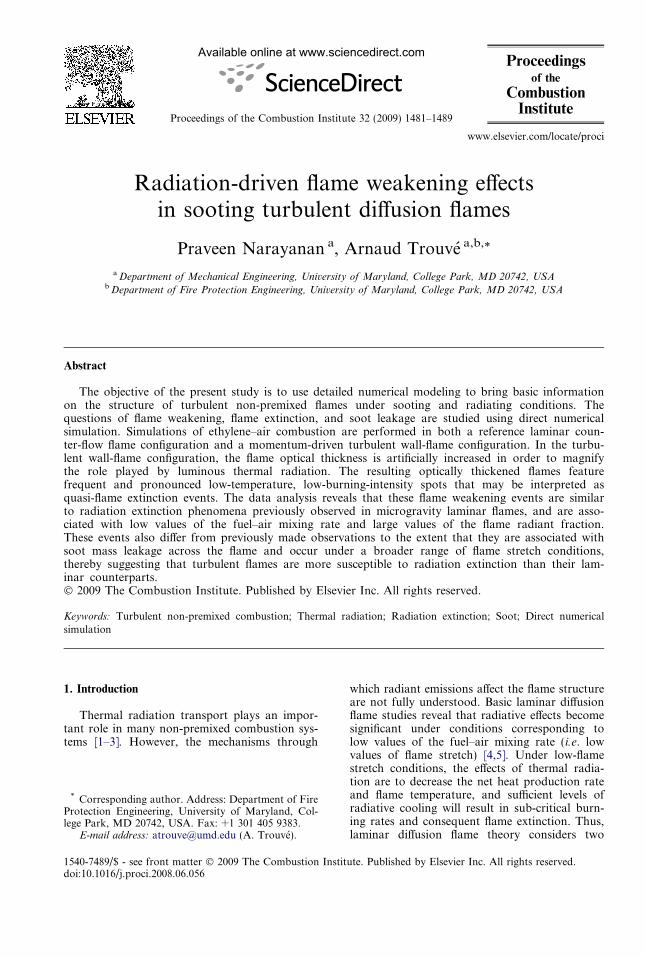
The interactions between diffusion flame, sootand thermal radiation processes were first ana-lyzed in a S3D-based study of strained laminarflames. This preliminary study considers the gen-eric case of steady, plane, counter-flow, ethyl-ene–air flames (without gravity); several flamestructures are calculated ranging from high- tolow-stretch conditions. The computationaldomain is two-dimensional (Fig. 1); its size variesfrom (Lx, Ly) = (1,1.2) under high-stretch condi-tions up to (Lx, Ly) = (260,650) under low-stretch
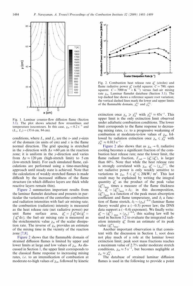
Fig. 1. Laminar counter-flow diffusion flame (Section3.1). The plot shows selected flow streamlines andtemperature isocontours. In this case, vst = 0.2 s�1 and(Lx, Ly) = (33.6 cm, 84 cm).
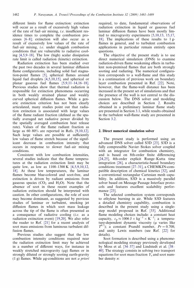
Fig. 2. Combustion heat release rate _q00c (circles) andflame radiative power _q00r (solid squares: C = 700; opensquares: C = 7000 m�1 � K�1) versus fuel–air mixingrate vst. Laminar flamelet database (Section 3.1). Thetop dashed line shows a reference square root variation;the vertical dashed lines mark the lower and upper limitsof the flammable domain, vLL
st and vULst .
1484 P. Narayanan, A. Trouve / Proceedings of the Combustion Institute 32 (2009) 1481–1489
conditions, where Lx and Ly are the x- and y-sizesof the domain (in units of cm) and x is the flamenormal direction. The grid spacing is stretchedin the x-direction with Dx �60 lm in the reactionzone; it is uniform in the y-direction and variesfrom Dy � 120 lm (high-stretch limit) to 5 cm(low-stretch limit). For each simulated flame, cal-culations are performed using a time-marchingapproach until steady state is achieved. Note thatthe calculation of weakly stretched flames is madedifficult by the increased stiffness of the flamestructure (in which diffusive layers are thick whilereactive layers remain thin).
Figure 2 summarizes important results fromthe laminar flamelet database and presents in par-ticular the variations of the centerline combustionand radiation intensities with fuel–air mixing rate;the combustion (radiation) intensity is measuredas the heat release rate (net radiative power) perunit flame surface area, _q00c ¼
R_q000c dxð _q00r ¼R
_q000r dxÞ; the fuel–air mixing rate is measured asthe stoichiometric value vst of the scalar dissipa-tion rate. The inverse of vst provides an estimateof the mixing time in the vicinity of the reactionzone [7,8].
Figure 2 shows that the flammable domain ofstrained diffusion flames is limited by upper andlower limits at large and low values of vst. As dis-cussed in Section 1, the upper limit corresponds tothe classical flame response to increasing mixingrates, i.e. to an intensification of combustion atmoderate-to-high values of vst, followed by kinetic
extinction once vst P vULst with vUL
st � 45s�1. Thisupper limit is the only extinction limit observedunder adiabatic combustion conditions. The lowerlimit corresponds to the flame response to decreas-ing mixing rates, i.e. to a progressive weakening ofcombustion at moderate-to-low values of vst, fol-lowed by radiation extinction once vst 6 vLL
st withvLL
st � 0:013 s�1.Figure 2 also shows that as vst ? 0, radiative
cooling becomes a significant fraction of the com-bustion heat release rate; near the lower limit, theflame radiant fraction, Crad ¼ ð _q00r = _q00c Þ, is largerthan 60%. Note that while the heat release rateis strongly correlated with vst, _q00c � ðvstÞ
0:5, thenet radiative power is only weakly sensitive tovariations in vst, 5 6 _q00r 6 20kW= m2. This lastresult may be explained by writing the integralquantity _q00r as the product of the peak valueð _q000r Þmax times a measure of the flame thicknessdf, _q00r ¼ ð _q000r Þmax � df ; in this decomposition,ð _q000r Þmax is a function of the peak mean absorptioncoefficient and flame temperature, and df a func-tion of flame stretch, df � (vst)
�0.4 (laminar flametheory would give a (�0.5) power law; the DNSdata support a (�0.4) exponent). We finally write:_q00r � ð _q000r Þ max � ðvstÞ
�0:4; this scaling law will beused in Section 3.2 to evaluate the integrated radi-ation intensity _q00r from an estimate of its peakvalue ð _q000r Þmax.
Another important observation is that consis-tent with the discussion in Section 1, soot doesnot play much of a role at the laminar lowerextinction limit; peak soot mass fractions reachesa maximum value of 2.7% under moderate stretchconditions, vst � 5 s�1, but becomes negligible atvst � vLL
st .The database of strained laminar diffusion
flames is used in the following to provide a point
P. Narayanan, A. Trouve / Proceedings of the Combustion Institute 32 (2009) 1481–1489 1485
of reference in the analysis of the more complexturbulent flame structures. Note that the simpli-fied flame-soot-radiation sub-models presented inSection 2 remain approximate and that many ofthe present results should be therefore interpretedin a qualitative rather than a quantitative manner.For instance, the choice of single-step chemistry isshown in Ref. [22] to produce underestimates ofthe combustion intensity. Also, the assumptionof an optically gray medium is known to produceoverestimates of radiation effects [5,9,17]. Finally,the value of the soot coefficient C in Eq. (3)remains questionable: C is determined by thevalue of the soot refractive index [41,42] andrecent measurements [45] suggest the followingrevised estimate: C = 1817 m�1 � K�1 (a valuethat is 2.6 times larger than that adopted in Sec-tion 2). In the next section, we adopt a ‘‘numericalexperiment” strategy in which in order to accentu-ate the role of luminous thermal radiation, theoptical thickness of the simulated flames is artifi-cially increased by multiplying the Planck meanabsorption coefficient of soot particles by an arbi-trary factor, C = 7000 m�1 � K�1, i.e. C is 10(3.85) times larger than our original choice (than
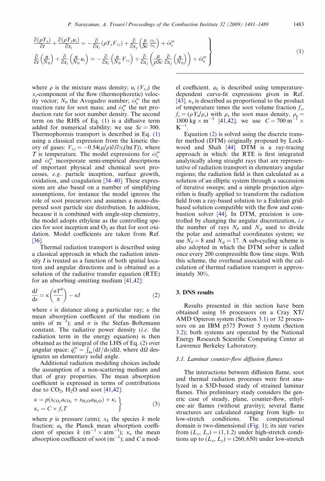
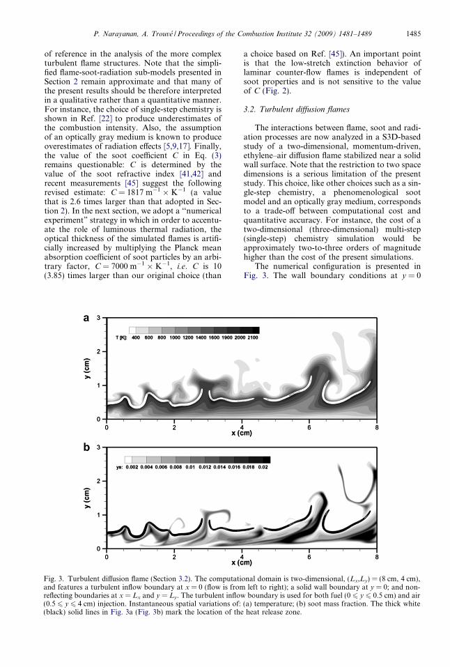
Fig. 3. Turbulent diffusion flame (Section 3.2). The computatiand features a turbulent inflow boundary at x = 0 (flow is fromreflecting boundaries at x = Lx and y = Ly. The turbulent inflow(0.5 6 y 6 4 cm) injection. Instantaneous spatial variations of:(black) solid lines in Fig. 3a (Fig. 3b) mark the location of the
a choice based on Ref. [45]). An important pointis that the low-stretch extinction behavior oflaminar counter-flow flames is independent ofsoot properties and is not sensitive to the valueof C (Fig. 2).
3.2. Turbulent diffusion flames
The interactions between flame, soot and radi-ation processes are now analyzed in a S3D-basedstudy of a two-dimensional, momentum-driven,ethylene–air diffusion flame stabilized near a solidwall surface. Note that the restriction to two spacedimensions is a serious limitation of the presentstudy. This choice, like other choices such as a sin-gle-step chemistry, a phenomenological sootmodel and an optically gray medium, correspondsto a trade-off between computational cost andquantitative accuracy. For instance, the cost of atwo-dimensional (three-dimensional) multi-step(single-step) chemistry simulation would beapproximately two-to-three orders of magnitudehigher than the cost of the present simulations.
The numerical configuration is presented inFig. 3. The wall boundary conditions at y = 0
onal domain is two-dimensional, (Lx,Ly) = (8 cm, 4 cm),left to right); a solid wall boundary at y = 0; and non-boundary is used for both fuel (0 6 y 6 0.5 cm) and air
(a) temperature; (b) soot mass fraction. The thick whiteheat release zone.
1486 P. Narayanan, A. Trouve / Proceedings of the Combustion Institute 32 (2009) 1481–1489
correspond to zero velocity, prescribed tempera-ture (300 K) and blackbody radiation. The inflowboundary conditions at x = 0 correspond toprescribed velocity, mixture composition and tem-perature. The free-stream corresponds to a uniformflow of air (u1 = 2.5 m/s) seeded with turbulent-like perturbations (characterized by a high forcingintensity, u0 = 1 m/s, and a small integral lengthscale, lt = 0.17 cm). The near-wall inflow velocityprofile has a boundary layer thickness d = 0.15 cm.Compared to Ref. [22], the inlet flame-to-wall dis-tance has been increased to 0.5 cm (and is signifi-cantly larger than d and lt) so that the simulatedflames are only weakly affected by the presence ofthe wall. Temperature and species mass fractionsare specified at x = 0 using a laminar flamelet solu-tion (Section 3.1).
The computational grid size is 1216 � 376. Thegrid spacing is uniform in the x-direction, Dx � 66lm, while variable in the y-direction: the y-grid isuniform in the near-wall and flame regions,Dy � 50 lm for 0 6 y 6 1.5 cm, and is stretchedin the free-stream region.
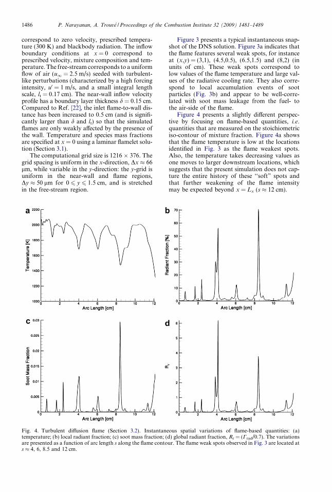
Fig. 4. Turbulent diffusion flame (Section 3.2). Instantanetemperature; (b) local radiant fraction; (c) soot mass fraction; (are presented as a function of arc length s along the flame contos � 4, 6, 8.5 and 12 cm.
Figure 3 presents a typical instantaneous snap-shot of the DNS solution. Figure 3a indicates thatthe flame features several weak spots, for instanceat (x,y) = (3,1), (4.5,0.5), (6.5,1.5) and (8,2) (inunits of cm). These weak spots correspond tolow values of the flame temperature and large val-ues of the radiative cooling rate. They also corre-spond to local accumulation events of sootparticles (Fig. 3b) and appear to be well-corre-lated with soot mass leakage from the fuel- tothe air-side of the flame.
Figure 4 presents a slightly different perspec-tive by focusing on flame-based quantities, i.e.quantities that are measured on the stoichiometriciso-contour of mixture fraction. Figure 4a showsthat the flame temperature is low at the locationsidentified in Fig. 3 as the flame weakest spots.Also, the temperature takes decreasing values asone moves to larger downstream locations, whichsuggests that the present simulation does not cap-ture the entire history of these ‘‘soft” spots andthat further weakening of the flame intensitymay be expected beyond x = Lx (s � 12 cm).
ous spatial variations of flame-based quantities: (a)d) global radiant fraction, Rr = (Crad/0.7). The variationsur. The flame weak spots observed in Fig. 3 are located at
P. Narayanan, A. Trouve / Proceedings of the Combustion Institute 32 (2009) 1481–1489 1487
Furthermore, it is found that the flame weakestspots correspond to minimum values of the fuel–air mixing rate vst. This demonstrates that thepresent flame dynamics are different from previ-ous flame extinction events studied in Ref. [22].In Ref. [22], the simulated flames were closer tothe cold wall, exposed to extensive wall-inducedconvective heat losses, and free of thermal radia-tion effects; flame extinction events correspondedto peak values of vst and were representative ofthe upper limit discussed in Section 3.1. In con-trast, in the present study, the flame soft spots cor-respond to minimum values of the mixing rate andto maximum values of the local radiant fraction(Fig. 4b), and may therefore be considered as rep-resentative of radiation-driven (lower limit) quasi-extinction phenomena.
Note that the local radiant fraction presentedin Fig. 4b is defined as the stoichiometric radia-tion-to-combustion power density ratio, Crad;st ¼ð _q000r = _q000c Þst, and is different from the global (spa-tially averaged) flame radiant fraction Crad
discussed in Section 3.1. While effects of thermalradiation occur over a zone of finite thickness,and are therefore better represented by a globallydefined quantity like Crad, Crad,st is easier toextract from the DNS database and is adoptedin Fig. 4b to give a quick first estimate (albeitqualitative) of the variations of Crad.
Figure 4b and c show that the variations ofCrad,st are strongly correlated with the presenceof soot mass. This result is consistent with the sootdistribution presented in Fig. 3b and with the sug-gestion that the flame weakest spots also corre-spond to soot mass leakage events [21]. Notethat these observations on soot are quite differentfrom those made in many previous laminar flamestudies in which extinction is driven by radiantemission from gaseous species and soot mass isessentially absent at the lower extinction limit(Section 1 and Section 3.1).
We now turn to a discussion of the radiationextinction criterion. This discussion is motivatedby the finding that the turbulent radiation-drivenquasi-extinction events occur at values of vst thatare significantly larger (by approximately an orderof magnitude) than the laminar lower limit vLL
st .First, we assume that radiation extinction occurswhen the global flame radiant fraction reaches acritical value of 0.7, independent of whether theflame is laminar or turbulent. Second, we adopta laminar flamelet viewpoint and assume thatthe turbulent combustion intensity follows classi-cal laminar flame scaling laws, _q00c � ðvstÞ
0:5. Wemay then re-write: Crad¼ 0:7ð _q00r = _q00LL
r ÞðvLLst =vstÞ
0:5,where vLL
st ( _q00LLr ) is the value of vst ( _q00r ) in a refer-
ence laminar flame at the lower extinction limit,vLL
st � 0:013s�1 ð _q00LLr � 10kW=m2Þ (Section 3.1),
and where vst and _q00r are properties that character-ize the state of a given turbulent flamelet. Flameextinction is then predicted to occur when:
vst 6 ðvLLst Þt; with ðvLL
st Þt ¼ vLLst
_q00r_q00LL
r
� �2
ð4Þ
where ðvLLst Þt designates the modified turbulent
lower extinction limit. Eq. (4) provides a usefulexpression to understand critical radiation condi-tions and shows in particular that radiationextinction is more readily achieved at low valuesof vst. In addition, Eq. (4) suggests that the radia-tion extinction limit may be quite different in lam-inar and turbulent flame configurations. Forinstance, while the radiative power _q00r remainslow in laminar flames (Section 3.1), the accumula-tion of soot mass in the turbulent case (Fig. 4c)will dramatically increase the flame luminosityand will result in significant differences betweenðvLL
st Þt and vLLst .
A simplified version of the criterion in Eq. (4) istested in Fig. 4d. This simplified version uses anexpression that can be evaluated using locallydefined flame-based quantities. First, we assumethat the radiation intensity follows the scaling lawdiscussed in Section 3.1, _q00r � ð _q000r Þmax � ðvstÞ
�0:4;we may then write: Crad ¼ 0:7ðð _q000r Þmax=ð _q000LL
r ÞmaxÞ�ðvLL
st =vstÞ0:9, where ð _q000LL
r Þmax is the peak value of_q00r in a reference laminar flame at the lower extinc-tion limit, ð _q000LL
r Þmax � 0:4MW=m3, and ð _q000r Þmaxthe same peak value in a given turbulent flamelet.Second, we assume that ð _q000r Þmax � ð _q000r Þst, whichgives: Crad ¼ 0:7ðð _q000r Þst= ð _q000LL
r ÞmaxÞ � ðvLLst =vstÞ
0:9.Using this expression, flame extinction is predic-ted to occur when: Rr ¼ ðð _q000r Þst=ð _q000LL
r ÞmaxÞ�ðvLL
st =vstÞ0:9 P 1. Figure 4d presents the instanta-
neous variations of Rr along the flame surface (atthe time selected for Fig. 4a–c) and shows that: Rr
takes vanishingly small values at locations onlyweakly affected by thermal radiation; and Rr takespeak values above 1 at the locations of the flameweakest spots, i.e. at locations that are onlystrongly affected by thermal radiation and are dri-ven to extinction. These results support the extinc-tion criterion proposed in Eq. (4).
4. Conclusion
DNS is used in this study to bring basic informa-tion on radiation extinction of diffusion flames inboth a laminar counter-flow configuration and aturbulent wall-bounded configuration. The simula-tions use a number of simplifications, e.g., single-step chemistry for combustion, a phenomenologi-cal soot model, and the optically gray gas assump-tion. In addition, the turbulent flame simulationsadopt a ‘‘numerical experiment” strategy in whichthe role of luminous thermal radiation is artificiallymagnified.
The simulated flames feature radiation-drivenflame weakening events. These events are similar toradiation extinction phenomena previously observedin microgravity laminar flames, and are associated
1488 P. Narayanan, A. Trouve / Proceedings of the Combustion Institute 32 (2009) 1481–1489
with slow fuel–air mixing conditions and large radi-ant losses. Unlike previous observations made inmicrogravity, the present flame weakening eventsare also associated with soot mass leakage acrossthe flame. Interestingly, these events provide a possi-ble phenomenology to explain the transition from a‘‘sooting” to a ‘‘smoking” flame; note that theseresults are consistent with a recent study of sootemission presented in Ref. [21].
In addition, the simulations suggest that tur-bulent radiation extinction occurs under abroader range of flame stretch conditions thanpreviously established in laminar studies. Anextinction criterion is proposed in Eq. (4). Thiscriterion suggests that due to the presence of sootmass and to the increase in flame luminosity, tur-bulent flames are more susceptible to radiationextinction than laminar flames. This criterionprovides a suitable basis for future evaluationsof the role of radiation in turbulent non-pre-mixed combustion applications.
Acknowledgment
This research is supported by the US Depart-ment of Energy, Office of Basic Energy Sciences,SciDAC Computational Chemistry Program(Grant No. DE-FG02-01ER15227) and by theUS National Science Foundation, Division ofChemical, Bioengineering, Environmental, andTransport Systems (Grant No. CTS-0553508).This research also benefited from helpful discus-sions on radiation extinction with Prof. P.B.Sunderland.
References
[1] P. Joulain, Proc. Combust. Inst. 27 (1998) 2691–2706.
[2] R. Viskanta, M.P. Menguc�, Prog. Energy Combust.Sci. 13 (1987) 97–160.
[3] S.R. Turns, Prog. Energy Combust. Sci. 21 (1995)361–385.
[4] B.H. Chao, C.K. Law, J.S. T’ien, Proc. Combust.Inst. 23 (1990) 523–531.
[5] J.S. T’ien, H. Bedir, Proc. 1st Asia-Pacific Conf.Combust., Osaka, Japan, 1997.
[6] A. Linan, Acta Astronaut 1 (1974) 1007–1039.[7] F.A. Williams, Combustion Theory, second ed.,
The Benjamin/Cummings Publishing Company,1985.
[8] N. Peters, Turbulent Combustion, Cambridge Uni-versity Press, 2000.
[9] T. Daguse, T. Croonenbroek, J.C. Rolon, N.Darabiha, A. Soufiani, Combust. Flame 106 (1996)271–287.
[10] A.J. Marchese, F.L. Dryer, Combust. Sci. Technol.124 (1996) 371–402.
[11] A. Atreya, A. Agrawal, Combust. Flame 115 (1998)372–382.
[12] S.H. Chan, J.Q. Yin, B.J. Shi, Combust. Flame 112(1998) 445–456.
[13] K. Maruta, M. Yoshida, H. Guo, Y. Ju, T. Niioka,Combust. Flame 112 (1998) 181–187.
[14] K. Mills, M. Matalon, Proc. Combust. Inst. 27(1998) 2535–2541.
[15] V. Nayagam, J.B. Haggard Jr., R.O. Colantonio,et al., AIAA J. 36 (8) (1998) 1369–1378.
[16] X.S. Bai, L. Fuchs, F. Mauss, Combust. Flame 120(2000) 285–300.
[17] S.D. Tse, D. Zhu, C.-J. Sung, Y. Ju, C.K. Law,Combust. Flame 125 (2001) 1265–1278.
[18] K.J. Santa, B.H. Chao, P.B. Sunderland, D.L.Urban, D.P. Stocker, R.L. Axelbaum, Combust.Flame 151 (2007) 665–675.
[19] G.H. Markstein, Proc. Combust. Inst. 20 (1984)1055–1061.
[20] G.H. Markstein, J. De Ris, Proc. Combust. Inst. 20(1984) 1637–1646.
[21] D.O. Lignell, J.H. Chen, P.J. Smith, T. Lu, C.K.Law, Combust. Flame 151 (2007) 2–28.
[22] Y. Wang, A. Trouve, Combust. Flame 144 (2006)461–475.
[23] Terascale High-Fidelity Simulations of TurbulentCombustion with Detailed Chemistry, SciDACProgram, DOE, Office of Basic Energy Sciences,Available at http://purl.org/net/tstc/.
[24] S.K. Lele, J. Comput. Phys. 103 (1992) 16–42.[25] C.A. Kennedy, M.H. Carpenter, Appl. Num. Math.
14 (4) (1994) 397–433.[26] C.A. Kennedy, M.H. Carpenter, R.H. Lewis, Appl.
Num. Math. 35 (3) (2000) 177–219.[27] T. Poinsot, S.K. Lele, J. Comput. Phys. 101 (1992)
104–129.[28] M. Baum, T. Poinsot, D. Thevenin, J. Comput.
Phys. 116 (1995) 247–261.[29] J.C. Sutherland, C.A. Kennedy, J. Comput. Phys.
191 (2003) 502–524.[30] C.S. Yoo, Y. Wang, A. Trouve, H.G. Im, Combust.
Theory Model. 9 (2005) 617–646.[31] C.S. Yoo, H.G. Im, Combust. Theory Model. 11
(2007) 259–286.[32] R.J. Kee, F.M. Rupley, E. Meeks, J.A. Miller,
CHEMKIN-III: a Fortran chemical kinetics pack-age for the analysis of gas-phase chemical andplasma kinetics, Report No. SAND96-8216, SandiaNational Laboratories, 1996.
[33] C.K. Westbrook, F.L. Dryer, Combust. Sci. Tech-nol. 27 (1981) 31–43.
[34] J.B. Moss, C.D. Stewart, K.J. Syed, Proc. Combust.Inst. 22 (1988) 413–423.
[35] K.J. Syed, C.D. Stewart, J.B. Moss, Proc. Combust.Inst. 23 (1990) 1533–1541.
[36] J.B. Moss, C.D. Stewart, K.J. Young, Combust.Flame 101 (1995) 491–500.
[37] S.J. Brookes, J.B. Moss, Combust. Flame 116 (1999)486–503.
[38] K.M. Leung, R.P. Lindstedt, W.P. Jones, Combust.Flame 87 (1991) 289–305.
[39] M. Fairweather, W.P. Jones, H.S. Ledin, R.P.Lindstedt, Proc. Combust. Inst. 24 (1992) 1067–1074.
[40] R.P. Lindstedt, in: H. Bockhorn (Ed.), Soot Forma-tion in Combustion, Springer-Verlag, 1994, pp. 417–439.
P. Narayanan, A. Trouve / Proceedings of the Combustion Institute 32 (2009) 1481–1489 1489
[41] R. Siegel, J.R. Howell, Thermal Radiation HeatTransfer, fourth ed., Taylor and Francis, 2001.
[42] M.F. Modest, Radiative Heat Transfer, second ed.,Academic Press, 2003.
[43] International Workshop on Measurement andComputation of Turbulent Nonpremixed Flames,
Sandia National Laboratories, Available at http://public.ca.sandia.gov/TNF/radiation.html.
[44] F.C. Lockwood, N.G. Shah, Proc. Combust. Inst.18 (1981) 1405–1414.
[45] T.C. Williams, C.R. Shaddix, K.A. Jensen, J.M. Suo-Anttila, Intl. J. Heat Mass Transfer 50 (2007) 1616–1630.